
ACHU300 - Air conditioner APC - Free user manual and instructions
Find the device manual for free ACHU300 APC in PDF.


| Product Type | Portable Air Conditioner |
| Brand | APC |
| Model | ACHU300 |
| Cooling Capacity | 9000 BTU/h |
| Dimensions (W x D x H) | 30 cm x 30 cm x 70 cm |
| Weight | 25 kg |
| Power Supply | 220-240 V ~ 50 Hz |
| Power Consumption | 1000 W |
| Refrigerant | R32 |
| Modes | Cool, Fan, Dehumidify |
| Fan Speeds | 3 speeds (Low, Medium, High) |
| Remote Control | Yes |
| Timer | 24-hour programmable timer |
| Air Flow (Max) | 350 m³/h |
| Noise Level (Max) | 50 dB(A) |
| Maintenance | Clean air filter every month |
| Safety Features | Auto shut-off, thermal protection |
| Spare Parts Available | Air filter, remote control |
| Reparability Index | 8/10 |
Frequently Asked Questions - ACHU300 APC
User questions about ACHU300 APC
0 question about this device. Answer the ones you know or ask your own.
Ask a new question about this device
Download the instructions for your Air conditioner in PDF format for free! Find your manual ACHU300 - APC and take your electronic device back in hand. On this page are published all the documents necessary for the use of your device. ACHU300 by APC.
USER MANUAL ACHU300 APC
InRow® Direct Expansion Air Conditioners
ACRH301 and ACHU300 Series
Operation and Maintenance
990-91476B-001
Release Date 07/2021
natural_image
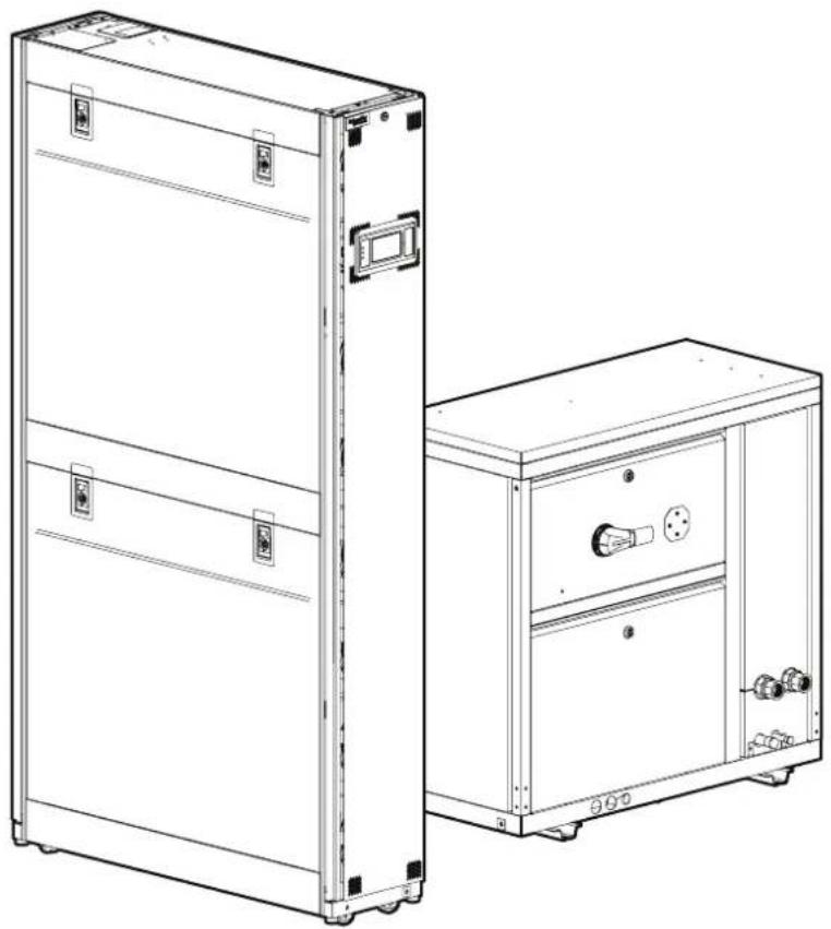
Technical line drawing of two modular electronic cabinets with control panels and buttons (no text or symbols)Legal Information
The Schneider Electric brand and any trademarks of Schneider Electric SE and its subsidiaries referred to in this guide are the property of Schneider Electric SE or its subsidiaries. All other brands may be trademarks of their respective owners.
This guide and its content are protected under applicable copyright laws and furnished for informational use only. No part of this guide may be reproduced or transmitted in any form or by any means (electronic, mechanical, photocopying, recording, or otherwise), for any purpose, without the prior written permission of Schneider Electric.
Schneider Electric does not grant any right or license for commercial use of the guide or its content, except for a non-exclusive and personal license to consult it on an "as is" basis. Schneider Electric products and equipment should be installed, operated, serviced, and maintained only by qualified personnel.
As standards, specifications, and designs change from time to time, information contained in this guide may be subject to change without notice.
To the extent permitted by applicable law, no responsibility or liability is assumed by Schneider Electric and its subsidiaries for any errors or omissions in the informational content of this material or consequences arising out of or resulting from the use of the information contained herein.
Table of Contents
Safety....7
Important Safety Instructions — SAVE THESE INSTRUCTIONS......7
Safety During Operation....8
General Information....10
Overview 10
Original Instructions ....10
Save These Instructions ....10
Cross-Reference Symbol Used in This Manual....10
Manual Updates ....10
Abbreviations ......10
Radio Frequency Interference 11
California Proposition 65—Warning Statement for California
Residents 11
Commissioning....12
Overview 12
Inspection Checklists ....12
Initial Inspection Checklist 12
Electrical Inspection Checklist....13
Mechanical Inspection Checklist 14
Display Interface Inspection Checklist 15
Start-Up Inspection Checklist....15
Final Inspection Checklist 16
Charging the Equipment....17
Calculating R410A Refrigerant Charge ....17
Refrigerant Charging Process....18
Oil Charging Procedure....19
Overview 21
InRow Advantages 21
Operation 22
Display Interface....22
Alarm LED 22
Status LED....23
Link-RX/TX (10/100) LED....23
Using the Display....24
Overview Screen 24
Home Screen/Main Menu 25
Display Controls 28
Using the Path Statement....28
Changing Settings 29
First Log In 30
Logging In/Password Entry 31
Tests 32
Calibrating the Display 32
Testing Display LEDs and Annunciator 32
Testing the AFC LED....32
General Configuration....33
Import and Export Unit Configuration....33
Export 33
Import 33
Cooling Unit Configuration....34
Configure the Unit ....34
Cooling Group Configuration 36
Configure the Cooling Group ....36
Configure Modbus ....36
Interface Connection ....37
A-Link Connections....38
Control the Environment....39
How the Modes of Operation Work ....39
Setpoints....40
Active Flow Controller (AFC) Settings....42
Run Hours and Service Intervals....44
Run Hours....44
Run Hours Settings....44
Service Intervals 45
User Security Settings ....46
Add a New User or Edit an Existing User ....46
Delete a User 46
Display Settings 46
Language, Date, Time, and Temperature 46
Screen Visibility and Audible Tones 48
Restore Defaults 48
Network Configuration....49
Configure the Network ....49
TCP/IPv4 Settings 49
TCP/IPv6 Settings 49
Web Access Settings ....49
FTP Server Settings....49
View Status Readings....50
Overview Screen 50
Cooling Unit Status ....51
Cooling Group Status....52
Sensor Readings....52
Refrigerant System 53
Power Information 54
Input/Output States....54
About the Network ....55
About the Unit 56
About the AFC....56
About the Display 56
Logs 57
Event Log 57
View Event Log....57
Filter Event Log ....58
Clear Event Log....58
Data Log 59
Data Log Configuration 59
Export Data....60
Alarms....61
Respond to Alarms 61
View Active Alarms 61
Clear Active Alarms....61
Alarm Thresholds....61
Alarm Messages and Suggested Actions 62
Network Management Card 68
Quick Configuration 68
Overview....68
TCP/IP Configuration Methods....68
Device IP Configuration Wizard....69
.ini File Utility 69
BootP and DHCP Configuration 69
Command Line Interface (CLI) 71
Access a Configured Unit 114
Overview.... 114
Web Interface 114
Telnet and SSH.... 115
Simple Network Management Protocol (SNMP) 115
FTP/SCP 116
Modbus.... 116
Recover From a Lost Password 117
Updating the Firmware.... 118
Update Display Firmware 118
Display Interface 118
Using a USB Drive to Transfer and Update Files 119
Verify Updates.... 121
Verify Success of the Transfer.... 121
Last Transfer Result Codes 121
Verify Version Numbers of Installed Firmware 121
Service Menu....122
Service Menu Access 122
Unit Configuration.... 122
Containment Systems.... 124
Run Hours and Service Intervals.... 126
Compressor Settings 126
Oil Return Management 127
PID Settings 128
Tune the PID Loop 131
Maintenance....132
Maintenance Mode 132
Monthly Preventive Maintenance 135
Quarterly Preventive Maintenance 138
Semi-Annual Preventive Maintenance.... 140
Troubleshooting 143
Safety
Important Safety Instructions — SAVE THESE INSTRUCTIONS
Read these instructions carefully and look at the equipment to become familiar with it before trying to install, operate, service or maintain it. The following safety messages may appear throughout this manual or on the equipment to warn of potential hazards or to call attention to information that clarifies or simplifies a procedure.

The addition of this symbol to a “Danger” or “Warning” safety message indicates that an electrical hazard exists which will result in personal injury if the instructions are not followed.

This is the safety alert symbol. It is used to alert the user to potential personal injury hazards. Obey all safety messages with this symbol to avoid possible injury or death.
⚠️ DANGER
DANGER indicates a hazardous situation which, if not avoided, will result in death or serious injury.
Failure to follow these instructions will result in death or serious injury.
▲WARNING
WARNING indicates a hazardous situation which, if not avoided, could result in death or serious injury.
Failure to follow these instructions can result in death, serious injury, or equipment damage.
▲CAUTION
CAUTION indicates a hazardous situation which, if not avoided, could result in minor or moderate injury.
Failure to follow these instructions can result in injury or equipment damage.
NOTICE
NOTICE is used to address practices not related to physical injury. The safety alert symbol shall not be used with this type of safety message.
Failure to follow these instructions can result in equipment damage.
Please Note
Electrical equipment should only be installed, operated, serviced, and maintained by qualified personnel. No responsibility is assumed by Schneider Electric for any consequences arising out of the use of this material.
A qualified person is one who has skills and knowledge related to the construction, installation, and operation of electrical equipment and has received safety training to recognize and avoid the hazards involved.
Always abide strictly by local laws and regulations in the place of installation.
Safety During Operation
⚠️ DANGER
HAZARD OF ELECTRIC SHOCK, EXPLOSION, OR ARC FLASH
- Apply appropriate personal protective equipment (PPE) and follow safe electrical work practices.
- This equipment must be installed and serviced by qualified and trained personnel only.
- Turn off all power supplying this equipment before working on or inside equipment.
- Replace all devices, doors, and covers before turning on power to this equipment.
Failure to follow these instructions will result in death or serious injury.
▲WARNING
HAZARD FROM MOVING PARTS
Keep hands, clothing, and jewelry away from moving parts. Check the equipment for foreign objects before closing the doors and starting the equipment.
Failure to follow these instructions can result in death, serious injury, or equipment damage.
▲WARNING
MOVING PARTS HAZARD
Do not remove rear panels if the equipment is operating.
Failure to follow these instructions can result in death, serious injury, or equipment damage.
▲WARNING
HAZARD TO EQUIPMENT OR PERSONNEL
All work must be performed by Schneider Electric qualified and trained personnel.
Failure to follow these instructions can result in death, serious injury, or equipment damage.
▲WARNING
HAZARD OF EQUIPMENT FALLING OVER
- Use two or more persons at all times to move or turn this equipment.
- Always push, pull, or turn while facing the front and rear of this equipment. Never push, pull, or turn while facing the sides of this equipment.
- Slowly move this equipment across uneven surfaces or door thresholds.
- Lower leveling feet to floor when this equipment is at rest.
- Lower leveling feet and attach joining brackets to adjacent racks when this equipment is in final position.
Failure to follow these instructions can result in death, serious injury, or equipment damage.
▲CAUTION
HAZARD TO EQUIPMENT OR PERSONNEL
Ensure that all spare parts and tools are removed from the equipment before operating.
Failure to follow these instructions can result in injury or equipment damage.
▲CAUTION
HAZARD OF HIGH PRESSURE REFRIGERANT OR EQUIPMENT DAMAGE
- Use R410A refrigerant only.
- Contents are under pressure: use caution when releasing pressure in the system or refilling.
- Charging and maintaining the refrigeration circuit must only be performed by qualified and certified personnel.
Failure to follow these instructions can result in injury or equipment damage.
General Information
Overview
Original Instructions
These are the original instructions provided by the manufacturer.
Save These Instructions
This manual contains important instructions that must be followed during the installation of this equipment.
Cross-Reference Symbol Used in This Manual

See another section of this document or another document for more information on this subject.
Manual Updates
Schneider Electric™ policy is one of continuous technological innovation and the company reserves the right to amend any data herein without prior notice. The images shown in this manual are for descriptive purposes only.
NOTE: Unit images and component identification information are examples only.
For any updates to this manual, please contact Schneider Elecviding the related part number displayed on the manual back cover.
Abbreviations
The following are abbreviations and terms used in this manual:
• EEV: Electronic expansion valve
• BMS: Building management system
• ATS: Automatic transfer switch
• HACS: Hot aisle containment system
• CACS: Cold aisle containment system
• RACS: Rack aisle containment system
• VFD/VSD: Variable-frequency drive/variable-speed drive
Radio Frequency Interference
The cooling units comply with part 15 of the FCC Rules. Operation is subject to the following two conditions:
- These devices may not cause harmful interference.
- These devices must accept any interference received, including interference that may cause undesired operation.
Any changes or modifications not expressly approved by the party responsible for compliance could void the user's authority to operate the equipment.
California Proposition 65—Warning Statement for California Residents
WARNING: This product can expose the user to chemicals including lead and lead compounds, that are known to the State of California to cause cancer and birth defects or other reproductive harm. For more information go to www.P65Warnings.ca.gov.
Commissioning
After installation, verify that all components are working properly and the equipment is ready to begin operation.
Overview
After installation, verify that all components are working properly and that the equipment is ready to begin operation.
-
Complete the following inspections:
-
Initial
- Electrical
- Mechanical
- Display interface
- Start-up
-
Final
-
Check the refrigerant charge in the system and add refrigerant if needed (see Charging the Equipment, page 17).
- Charge the system with oil (see Oil Charging Procedure, page 19).
Inspection Checklists
Initial Inspection Checklist
▲WARNING
DAMAGE TO EQUIPMENT AND PERSONNEL
Do not run service utilities in front of the fan outlet.
Failure to follow these instructions can result in death, serious injury, or equipment damage.
The initial inspection ensures that the equipment has been properly installed. The location of the cooling unit has been properly prepared and the cooling unit is free of damage.
NOTE: The vapor barrier minimizes moisture infiltration. Without a vapor barrier, it will be difficult to maintain the humidity in the room. Do not introduce unconditioned outside air into the space.
Ensure that
☐ The installation procedure is complete according to the requirements of the installation manual and local codes.
☐ The walls, floor, and ceiling of the room where the cooling unit is located are sealed with a vapor barrier.
☐ There is no evidence of damage to the cooling unit.
☐ Clearance around the equipment is in accordance with CE, local, and national codes as well as the installation manual.
☐ The cooling unit is level and joined to the adjacent racks.
☐ The cooling unit is not installed at the open end of a row.
Electrical Inspection Checklist
⚠️! DANGER
HAZARD OF ELECTRIC SHOCK, EXPLOSION, OR ARC FLASH
- Apply appropriate personal protective equipment (PPE) and follow safe electrical work practices.
- This equipment must be installed and serviced by qualified and trained personnel only.
- Turn off all power supplying this equipment before working on or inside the equipment.
- Replace all devices, doors, and covers before turning on power to this equipment.
Failure to follow these instructions will result in death or serious injury.
⚠️ ⚠️ WARNING
ELECTRICAL HAZARD
- Electrical service must conform to local and national electrical codes and regulations.
- The equipment must be grounded.
Failure to follow these instructions can result in death, serious injury, or equipment damage.
The electrical inspection verifies that all electrical connections are secure and correct and that the equipment is properly grounded.
Ensure that
☐ Incoming voltages match the phase and voltage rating on the nameplate.
Electrical wiring complies with local and national codes and regulations.
☐ Equipment is properly connected to an earth ground.
Front and rear doors for the indoor unit and doors for the outdoor are properly grounded.
Internal electrical components and terminal blocks do not have any loose connections.
Electrical connections are tight, including contactors, terminal blocks, controllers, switches, relays, auxiliary devices, and field connections.
☐ The primary and secondary power feeds (if applicable) are properly connected.
☐ Circuit breakers are correct and securely attached to the DIN rail.
☐ The rack temperature sensors are installed correctly for InRow and CACS modes.
☐ The optional rope water detection device is installed properly.
☐ The temperature and humidity sensors are connected correctly.

See the Installation Manual for the unit for installation procedures.
Mechanical Inspection Checklist
▲CAUTION
HAZARD TO EQUIPMENT OR PERSONNEL
- The equipment is shipped from the factory with a nitrogen holding charge. Remove the nitrogen holding charge using the service ports located on the internal refrigerant piping.
- Improperly installed piping may result in improper operation and possible damage to the cooling unit or surrounding equipment.
Failure to follow these instructions can result in injury or equipment damage.
The mechanical inspection verifies that all mechanical components and connections are secure and tight and ready for start-up. The inspection ensures that field piping is properly installed to promote oil return to the compressor.
Ensure that
☐ The condensate drain line is the size of the drain connection and has proper slope away from the unit.
Mechanical connections are tight, including water piping, refrigerant piping and the condensate drain line.
☐ Refrigerant piping size is correct according to the line size table in the installation manual.
☐ Vertical, horizontal, and total run lengths are recorded for liquid and gas lines.
Field-installed traps and piping are in accordance with the installation manual and follow proper piping practices.
☐ The number of 45- and 90-degree bends in the refrigerant piping are recorded.
Room conditions comply with the operating guidelines before starting the equipment.
☐ Covers and guards are in place.
☐ Piping is adequately supported and isolated when necessary.
☐ Piping in the building and on the roof is properly insulated.
☐ Piping has been leak tested and held a vacuum prior to introduction to refrigerant into the system.
Indoor units: Check that the indicator paper in the sight glass is a green color.
Field-installed service valves are open.
Display Interface Inspection Checklist
The display interface inspection verifies that the sensors and internal communication links are installed properly. Check that the cooling unit is connected to the other cooling units in the room if you are using cooling group controls.
Ensure that
An A-Link bus is connected to each cooling unit and a terminator is plugged into all unused A-Link connections.
☐ The input contacts and output relays are connected correctly.
☐ The building management system is connected correctly and a terminator is wired into the final cooling unit between Modbus D0 and Modbus D1.
☐ The network port is connected correctly and an IP address has been assigned to the equipment.
Start-Up Inspection Checklist
The start-up inspection ensures that the equipment is operating properly after the initial start-up. This inspection verifies that all modes of operation are working correctly and that the cooling unit is ready for normal operation.
While the equipment is operating, ensure that
☐ The cooling unit is free from malfunctions, including water leaks, unusual vibrations, or other irregularities in each mode of operation.
Air filters are clean and free of debris. Replace air filters if necessary.
☐ If applicable, perform an air balance to verify that the fans are set to the desired fan speed.
☐ If equipped, the condensate pump is working properly by adding fresh clean water to the condensate pan and checking pump operation.
☐ Temperature and humidity sensors are working properly.
☐ Compressor suction and discharge pressures are within normal range.
☐ The compressor oil level is at least 1/3 in sight glass.
☐ The cooling unit has the proper refrigerant charge for year-round operation.
☐ The high-pressure switch is operating correctly.
- Shut down the condenser fan.
- The head-pressure will rise until the high-pressure switch shuts down the compressor.
- Record the shut-off point.
Final Inspection Checklist
The final inspection verifies that the system is clean, the installed options work properly, and the start-up form is sent to Schneider Electric.
Ensure that
☐ Interior and exterior of the equipment are clean and free from debris and loose hardware.
Internal protective covers and hardware are installed.
Packaging materials are disposed of properly.
There are no active alarms.
☐ Customer is trained on the user display and is able to view active alarms and status readings.
☐ The customer is given the technical support contact number applicable for their region.
Unit documentation has been given to the customer.
☐ Start-up form is filled in and sent to Schneider Electric.
Charging the Equipment
▲WARNING
HAZARD TO EQUIPMENT OR PERSONNEL
All work must be performed by Schneider Electric qualified and trained personnel.
Failure to follow these instructions can result in death, serious injury, or equipment damage.
▲CAUTION
HAZARD OF HIGH PRESSURE REFRIGERANT OR EQUIPMENT DAMAGE
- Use R410A refrigerant only.
- Use hose and manifold set suitable for R410A with a minimum pressure rating of 50 bar (725 PSIG).
- The unit display should be used to obtain pressure readings.
Failure to follow these instructions can result in injury or equipment damage.
Calculating R410A Refrigerant Charge
| Model | Nominal Charge |
| ACHU300, ACHU302 7.5kg (16.5lb) | |
| ACHU300-L, ACHU302-L 10.5kg (23.1lb) |
The total system charge has to be adjusted based on the liquid line length as shown in the table below.
| ACR Tube Sizing - in. | Wall Thickness - mm | Cross-Section - mm2 | Refrigerant Charge - kg/m (lb/ft) |
| 1/2 0.89 94 0.094 | (0.063) | ||
| 5/8 1.02 | 150 | 0.151 (0.101) | |
| 3/4 1.07 | 224 | 0.226 (0.151) | |
| 7/8 1.14 | 312 | 0.314 (0.211) |
Refrigerant Charging Process
R410A is a mixed refrigerant. When charging this equipment with mixed refrigerant, only liquid refrigerant must be used.
NOTE: The equipment must be charged only with R410A refrigerant. The installing contractor is responsible for providing sufficient refrigerant for a complete system charge during start-up.

See Component Identification section in the Installation Manual for the location of service ports.
- Pressurize the system to 17.2 bar (250 PSI) with nitrogen (use the service and discharge ports). Leave the system pressurized for 24 hours then check the gauges for a drop in pressure.
- Use a vacuum pump and pull the first vacuum down to 750 microns (use the vacuum ports on the connection piping). The initial pull-down can take up to 24 hours.
- Once the vacuum level has reached 750 microns, close the manifold gauge valves and turn off the vacuum pump. Wait for one hour (the vacuum should not rise above 1500 microns) and then break the vacuum with nitrogen gas (use the service and discharge ports) until the system pressure equals atmospheric pressure.
- Pull a final vacuum down to 300 microns for a minimum of two hours.
- Charge with liquid R410A refrigerant through the service port and needle valve on the condenser until the pressure equalizes with the refrigerant canister.
- Open the ball valves and start the system. Charge the refrigerant slowly through the suction.
Oil Charging Procedure
▲WARNING
HAZARD TO EQUIPMENT OR PERSONNEL
All work must be performed by Schneider Electric qualified and trained personnel.
Failure to follow these instructions can result in death, serious injury, or equipment damage.
NOTICE
DAMAGE TO EQUIPMENT
Do not charge the compressor with too much oil: compressor damage could result. The only way to drain oil from the compressor is to remove the compressor from the equipment. The following system damage could also occur:
- Failure of valves and pistons due to oil slugging.
- Excessive oil carryover.
- Loss of evaporator performance due to oil level build-up in the low-pressure side of the system.
Failure to follow these instructions can result in equipment damage.
The system must be field-charged with 600 ml (20 oz) of PVE oil to make sure the system functions normally.
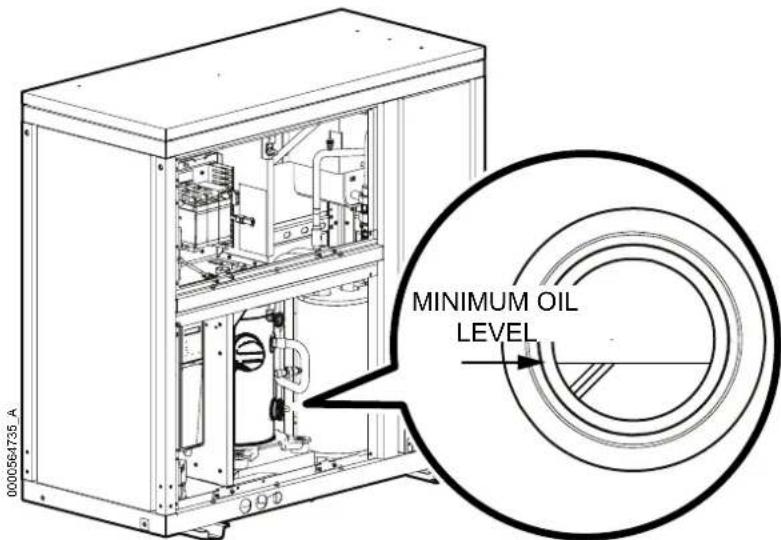
In installations with good oil return and line runs up to 15 m (49 ft), no additional above the initial 600 ml (20 oz) of oil is required. If the installation lines exceed 15 m (49 ft), additional oil may be needed. 1% or 2% of the total system refrigerant charge can be used to calculate the required oil. Regardless, the oil charge has to be adjusted based on the oil level in the compressor sight glass: the oil level must be no lower than 1/3 in the sight glass when the compressor is running.
Use the following oil type:
• PVE (Daphne Hermetic Oil FVC32D)
Use the following calculations to get the total charge amount:
- Metric
Total oil charge in ml = 600 ml + (charge in kg) * 0.02 * 1000
Example: Charge = 25 kg
600 ml + (25 * 0.02 * 1000) = 600 + 500 = 1100 ml
- US Standard
Total oil charge in oz = 20 oz + [(charge in lb)/2.2046] * 0.02 * 33.8
Example: Charge = 55.1 lb
20 oz + (55.1/2.2046) * 0.02 * 33.8 = 20 + (25 * 0.02 * 33.8) = 20 + 16.9
36.9 oz
- Prepare to add oil:
a. Use a new sealed oil can and a manual oil pump. The pump hose must be sized for 1/4 in. flare fittings and must include a valve depressor at its end, which will open the valve on the suction port of the compressor.
b. Use Daphne Hermetic PVE Oil FVC32D. Any other oil must be approved by Schneider Electric before using.
- Purge the pump and hose
a. Ensure that the oil pump is clean. Insert the pump in the oil container and make sure that the container is open to the atmosphere for as short a period of time as possible. When available, use a plug adapter kit to further reduce the exposure of the oil to the atmosphere.
b. Bleed all air from the pump and hose with a few strokes of the pump. Purging the pump removes the moisture-saturated oil left inside the hose from previous usage.
c. Connect the hose to the suction port of the compressor immediately after purging to avoid moisture contamination.
-
While the equipment is running, charge 600 ml (20 oz) PVE oil through the suction port. Pump the oil very slowly. (This is to ensure the oil separator is functioning properly.)
-
Other than the amount required for the oil separator, no additional oil should be required. Let the compressor run at full capacity for at least one hour and check the oil level in the oil sight glass. The level should be between 1/3 and 2/3 full, or within the limit shown on the oil level sticker. If the oil is not within the acceptable limit, check the oil return line for restrictions. When oil is flowing properly, the oil return line should feel warm to the touch.
NOTE: Dispose of the oil waste appropriately.
Overview
The ACRH301 series of indoor units can provide a cooling capacity based on a half-rack platform (300 mm (12 in.)) with an ACHU300 series outdoor unit. A variable-speed compressor works with EC fans and a fin-tube exchanger to reach the best cooling efficiency.
This modular, row-based computer room cooling system offers efficient, predictable, and economical cooling for a variety of spaces.
Critical environmental requirements now reach far beyond the confines of the traditional data center or computer room to encompass a larger suite of applications, referred to as technology rooms. Critical environment applications include the following:
- Computer rooms
• Telecommunication facilities - Clean rooms
• Power equipment
• Medical equipment rooms
• LAN/WAN environments - Edge data centers
• Traditional data centers
InRow Advantages
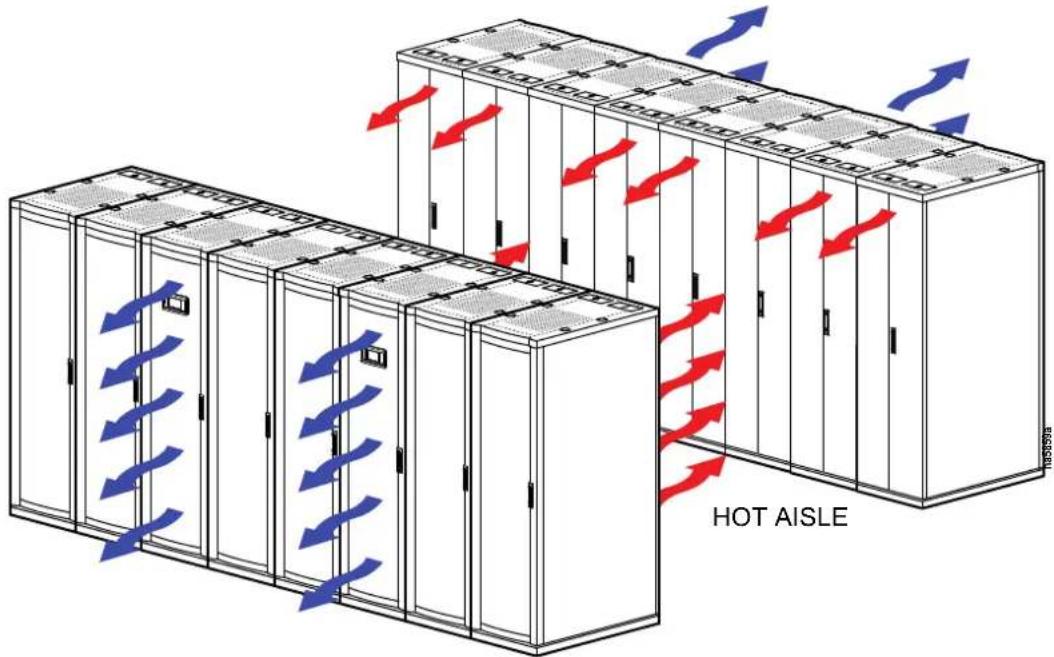
The row-based solution improves energy efficiency and cooling ability in a number of ways. First, the Uniflair Direct Expansion InRow unit draws air directly from the hot aisle, allowing the unit to take advantage of higher heat transfer efficiency due to higher temperature differences. It can then discharge room-temperature air directly in front of the servers it is cooling. Placing the unit in the row enables the unit to operate at higher return and supply air temperatures, yielding 100% sensible capacity. This significantly reduces the need for humidification.
Operation
Display Interface
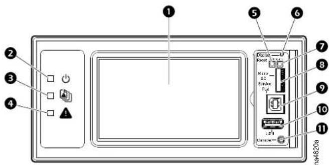
Item Description Function
| 1 | LCD Display | 4.3-inch touch-screen color display |
| 2 | Power LED The cooling unit is powered when the LED is illuminated. Unit firmware is updating when LED is blinking. | |
| 3 | Check Log LED | When this LED is illuminated, a new entry has been made to the event log. |
| 4 | Alarm LED | Displays current alarm condition of unit. |
| 5 | Status LED | Displays current network management card status. |
| 6 | Display Reset button | Resets the display microprocessor. This has no effect on the air conditioner controller. |
| 7 | Link-RX/TX (10/100) LED | Displays current network link status. |
| 8 | Micro SD card slot | Memory card expansion slot. |
| 9 | Service port USB-B port used only by service personnel. | |
| 10 | USB-A port Supports firmware upgrades. | |
| 11 | Serial Configuration port Connects the display to a local computer to configure initial network settings or access the command line interface (CLI). | |
Alarm LED
This LED indicates active alarms on the display.
| Condition | Description |
| Off | No alarm |
| Solid yellow | Warning alarm |
| Solid red Critical alarm |
Status LED
This LED displays current network management card status and display status.
| Condition | Description |
| Off One of the following situations exist:The display is not receiving input power.The display is not operating properly. It may need to be repaired or replaced. Contact Schneider Electric Customer Support. | |
| Solid green The display has valid TCP/IP settings. | |
| Solid orange A hardware malfunction has been detected in the display. Contact Schneider Electric Customer Support. | |
| Flashing green | The display does not have valid TCP/IP settings. |
| Flashing orange | The display is making BOOTP requests. |
| Alternately flashing green and orange | If the LED is flashing slowly, the display is making DHCP requests. If the LED is flashing rapidly, the display is starting up. |
Link-RX/TX (10/100) LED
This LED indicates the network status of the display.
| Condition | Description |
| Off One or more of the following situations exist:The display is not receiving input power.The cable or device that connects the cooling unit to the network is disconnected or not functioning properly.The display itself is not operating properly. It may need to be repaired or replaced. Contact Schneider Electric Customer Support. | |
| Solid green | The display is connected to a network operating at 10 megabits per second (Mbps). |
| Solid orange The display is connected to a network operating at 100 Mbps. | |
| Flashing green The display is receiving or transmitting at 10 Mbps. | |
| Flashing orange The display is receiving data packets at 100 Mbps. | |
Using the Display
The display initializes and runs a LED test when power is applied to the cooling unit.
Overview Screen
After start-up, the display shows an overview screen containing basic status information. Press Home to toggle between the main menu and overview screen. After a period of inactivity, the display reverts back to the overview screen.
NOTE: To maintain cleanliness and optimal performance of the touch-screen surface, it is recommended to use a soft-tip stylus when using the display. Never use sharp or hard-pointed objects on the touch-screen surface.
NOTE: Images are examples only to show operation of the display interface. Screens on your unit may vary.
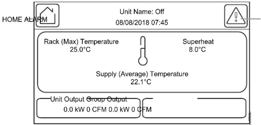
Home Screen/Main Menu
At any time during operation, press Home to return to the main menu. While on the main menu, press Home to toggle between the home and overview screen. To view active alarms, press Alarms.

See Alarms, page 61 for more information.
The Alarms button changes based on the current state of the unit.
Symbol Description


No alarms: No alarms are present.
Informational: Provides details on an alarms that are not a warning or critical.
Warning: An alarm condition requires attention and could jeopardize your data or equipment if its cause is not addressed.
Critical: A critical alarm exists, which requires immediate action.
Main menu options appear on the display as shown in the example below.
NOTE: Menus will vary depending on unit type.
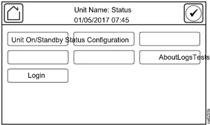
Menu Description
- ON/Off: The On/Off screen is used to turn the unit on or off and configure operational settings for the unit.

See Operation Settings, page 34.
- Status: Contains menus with sensor reading information, unit operation information, runtimes and counters, and component information.

See View Status Readings, page 50.
- Configuration: Contains menus for user-configurable settings for the unit and network. The Service menu is also located here.
Unit: Contains menus for configuring the operational behavior of the cooling unit.

See Cooling Unit Configuration, page 34.
- Group: Contains menus for configuring the operational behavior of the cooling group.

See Cooling Group Configuration, page 36.
- Containment Systems: Contains settings related to the AFC.

See Active Flow Controller (AFC) Settings, page 42.
Service: Contains menus for configuring the unit and manually controlling components for servicing. This menu is to be accessed by qualified service personnel only.

See Service Menu, page 122.
• Display: Contains menus for display settings, user preferences, and user access.

See Display Settings, page 46.
- Network: Contains menus for configuring the network settings.

See Configure the Network, page 49.
Modbus: Contains settings to configure Modbus TCP settings.

See Configure Modbus, page 36.
Restore Defaults: Contains options to restart the display.

See Restore Defaults, page 48.
- Tests: Contains menus to calibrate the touch screen and test the display LEDs.

See Tests, page 32.
- Logs: These screens save status information and record events and configuration changes.

See Logs, page 57.
- About: These screens display identifying information that is helpful when obtaining service.

See About the Network, page 55, About the Unit, page 56, and About the Display, page 56
- Login/Logout: Used to log into or log out of the unit.

See Logging In/Password Entry, page 31.
Display Controls
To view a sub-menu, select an option from the main menu. Continue this process until the appropriate menu is active.
During navigation, the current file path is displayed at the top of the screen. Clicking on any of the headers reverts the display to the specified menu.
Menus with multiple pages use arrows to move between pages. Forward and Back advance one page at a time while First and Last move directly to the first or last page within the menu. Once changes have been made within a menu, press OK to confirm changes or ESC to cancel.
NOTE: Images are examples only to show operation of the display interface. Screens on your unit may vary.
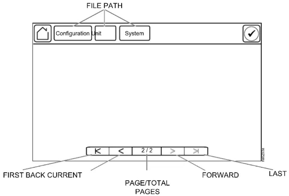
Using the Path Statement
Select the main- and sub-menu options specified in the path statement to view or configure a setting. The path statement lists the main- and sub-menu options you select to navigate to the setting you want to view or modify. The parts of the path statement are defined in the following example:
Path: Main > Status > Unit Overview
Main > Your starting point is the main menu.
Status > Select this option from the main menu.
Unit Overview > Select this option from the sub-menu.
Subsequent options are listed and defined under the path statement.
Changing Settings
NOTE: Images are examples only to show operation of the display interface. Screens on your unit may vary.
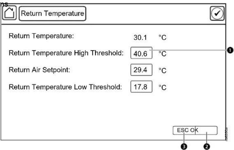
Screens that have mixed types of settings (e.g. list items and field items) require changes to be confirmed individually after being changed.
- Select the option or enter a value for the setting to be changed.
a. For list items①, press the up and down arrows to select the setting
b. For field item③, enter a value for the setting.
- Press OK ^② to confirm after each individual setting change.
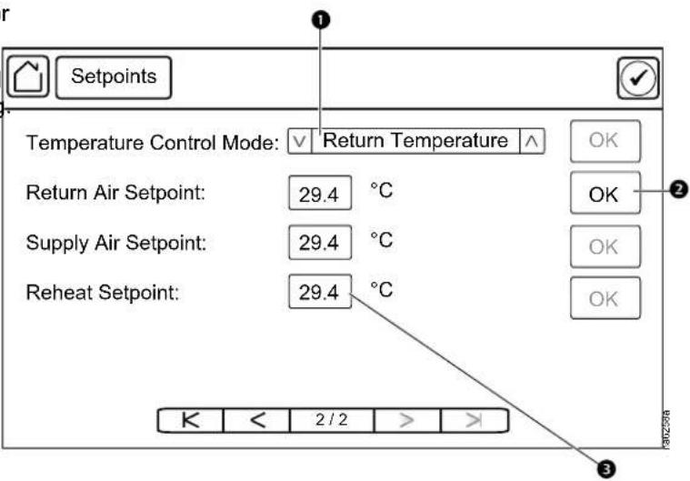
Screens that only contain field items can be confirmed together with a single OK button.
-
Enter a value for any or all field item ①.
-
Press OK ^② to confirm all changes at once, or press ESC to exit without accepting changes ^③ .
First Log In
The first time you log in to the unit at the display interface, you will be prompted to enable the device account. You can connect to the Network Management Card to enable the account and set the password in any of the following ways :
- HTTPS

See Web Interface, page 114 for information on accessing the Web interface. See the Online Guide for your unit, available from the Schneider Electric Web site (www.se.com), for more information on the Web interface.
- SSH

See Telnet and SSH, page 115 for information on connecting through Secure SHell.
- Console port

See Command Line Interface (CLI), page 71 for information on connecting through the console port on the display interface.
Logging In/Password Entry
Path: Main > Login
The unit display interface requires password verification before settings can be altered on the unit. You can log in from the main menu by selecting Login. While is not required to log in to view unit configurations, it is required to make any changes.
- Select Login.
- Select your login ID with the up and down arrows ^① .
NOTE: The default user ID is apc. - Enter your password in the Pin field ② with the keypad.
NOTE: The default password is 1234.
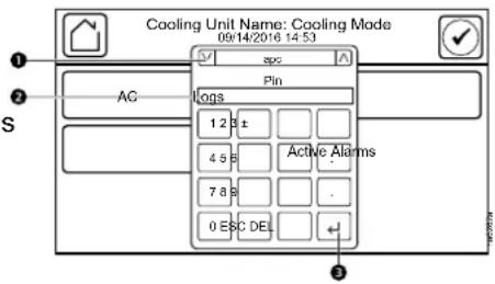
- Select Enter ^3 .
If the password was not entered from the Login screen on the main menu, you will be prompted to enter the password when attempting to change a setting. The unit default password is 1234.

See Add a New User or Edit an Existing User, page 46 for information on editing users and passwords.
The Home button visually changes to signify that a user is currently logged in.
Symbol Description

Home when the system is locked.

Home when the system has been unlocked by a user.
After the password is entered, user login remains active until the period of inactivity exceeds the Auto Logoff setting.

See Screen Visibility and Audible Tones, page 48.
Tests
Calibrating the Display
Path: Main > Tests > Display Calibration > Calibrate
Use this screen to calibrate the touch screen by touching the center of the box that appears on the screen. When you are satisfied with the calibration, let the timer run down to zero.
NOTE: The touch screen will need to be calibrated every time the firmware on the touch screen is updated.
Path: Main > Tests > Display Calibration > Calibration Check
Use this screen to test the accuracy of the touch screen calibration by touching the center of the box that appears on the screen. When you are satisfied with the test, let the timer run down to zero.
NOTE: The touch screen will need to be calibrated every time the firmware on the touch screen is updated.
Testing Display LEDs and Annunciator
Path: Main > Tests > Annunciators
- Press Start to test the display LEDs and annunciator.
The display LEDs will cycle through a green, orange, and red illumination pattern and the annunciator will sound.
- Press Stop to stop testing.
Testing the AFC LED
Path: Main > Configuration > Service > Containment Systems
- Select On for Active Flow Control Lamp Test and press OK to test the Active Flow Controller (AFC) LED.
The AFC LED will cycle through a red, green, and blue illumination pattern.
- Select Off for Active Flow Control Lamp Test and press OK to stop the LED test.
General Configuration
Import and Export Unit Configuration
It is possible to configure a cooling unit by importing the settings of another cooling unit from a USB drive.
Export
- Navigate to Main > Configuration > Service > USB.
- Insert the USB drive into the USB port on the display.
- Press Export.
The configuration of the unit will be exported to the USB drive.
A message stating “Abort export of data to USB drive” will disappear when exporting is complete.
- Remove the USB drive from the USB port.
Import
- Navigate to Main > Configuration > Service > USB .
- Insert the USB drive into the USB port on the display.
- Press Import.
The configuration of the unit will be downloaded from the USB drive.
- Press OK when the "Import Complete" message appears.
- Remove the USB drive from the USB port.
Cooling Unit Configuration
The cooling unit configuration options are set during the commissioning of the cooling units in the cooling group.
NOTE: Changing the settings incorrectly can cause malfunctions to your cooling unit. Only qualified service personnel should make changes to these settings.
NOTE: Displayed settings may vary based on model.
Configure the Unit
Operation Settings
Path: Main > On/Off
Settings in the On/Off menu control how the cooling unit will operate.
NOTE: Changing the settings incorrectly can cause malfunctions to your cooling unit. Only qualified service personnel should make changes to these settings.
NOTE: Displayed settings may vary based on model.
- Unit: Select whether the unit is Off or On.
- Startup Delay: Enter a value for the start-up in seconds. The startup delay begins when power is applied to the cooling unit. The cooling unit cannot begin operation until this delay expires. Use the startup delay to restart equipment sequentially in your room after a scheduled downtime or a power outage. (0–999 s)
- Cooling Strategy: Select the cooling strategy used to control the operation of the unit. (RACS, HACS, INROW, CACS, Manual)

See the How the Modes of Operation Work, page 39 for more information on the types of cooling strategy.
- Supply Air Setpoint: The Supply Air Setpoint is the required temperature of the air expelled into the surrounding environment. (15.0–30.2°C (59.0–86.4°F))
NOTE: The minimum setpoint (15°C (59°F) is suggested when the load is close to the minimum load or when the outdoor air temperature is lower than 0°C (32°F).
- Cool Setpoint: Set the temperature that the cooling group should maintain in the IT space. (17.8–35.0°C (64.0–95.0°F))
- Delta-T Setpoint: When the group is programmed for HACS or RACS mode, this value specifies the desired temperature difference between the supply and return air temperatures when an AFC is not present. (10F/5.6C, 15F/8.3C, 20F/11.1C, 25F/13.9C, 30F/16.7C, 35F/19.4C, 40F/22.2C)
NOTE: Set a lower Cool Setpoint or a smaller Delta-T Setpoint to assist with start-up during winter.
- Maximum Fan Speed: Set the maximum fan speed percentage allowed for the evaporator fans. (30.0–100.0% for one power supply, 30.0–130.0% for two power supplies)
- Manual IT Fan Speed: Enter a fan speed percentage to manually control the fans in the unit. (20–130%)
NOTE: The fan speed cannot exceed the Maximum Fan Speed.
- Unit Role Override: Determines the role of the cooling unit in the group.
• Automatic: Allows the system to select the role of the cooling unit.
- Forced On: Select Forced On if you have Runtime Balancing Enable selected and you DO NOT want a particular unit in the group to become a backup unit.
NOTE: Runtime Balancing Enable can be changed on the Main > Configuration > Group > Cooling screen.
- Idle on Leak Detect: When set to Yes, the cooling unit will enter idle mode if a Leak Detected Critical alarm activates. Set to No to disable the cooling unit from entering idle mode if a leak is detected.
- Shutdown Input State: Displays the current state of the shutdown input.
- Shutdown Input Present: Select whether a shutdown input is present in the unit.
NOTE: Same setting as on Main > Configuration > Unit > Components.
- Shutdown Input Normal State: Select the normal state of the shutdown input. (Open, Closed)
NOTE: Same setting as on Main > Configuration > Unit > Components.
- Protect On/Standby: Select Enable to password protect the Main > On/Off menu.
Component Configuration
Path: Main > Configuration > Unit > Components
NOTE: Changing the settings incorrectly can cause malfunctions to your cooling unit. Only qualified service personnel should make changes to these settings. Displayed settings may vary based on model.
• Voltage: Displays the voltage of the unit. (Not Configured, 100-120v, 200-240v)
NOTE: This is a read-only value.
• Number of Evaporator Fan Power Supplies: Set the number of fan power supplies installed in the electrical box. (1 or 2)
- Condensate Pump Hold Time: Set the length of time that the pump will continue to run after the lower condensate float switch is deactivated. (0–120 s)
- Air Filter Type: Select whether the air filters are Standard or High Efficiency.
- Number of Rack Inlet Temp Sensors in Unit: Set the number of rack inlet air temperature sensors connected to the unit. (0–4)
- Number of Leak Detectors in Unit: Set the number of leak sensors connected to the unit. (0–4)
- Shutdown Input State: Displays the current state of the shutdown input.
- Shutdown Input Present: Select whether a shutdown input is present in the unit.
- Shutdown Input Normal State: Select the normal state of the shutdown input. (Open, Closed)
Cooling Group Configuration
The cooling group configuration settings determine which components are available and how the cooling group should operate.
NOTE: Changing the settings incorrectly can cause malfunctions to your cooling unit. Only qualified service personnel should make changes to these settings.
NOTE: Displayed settings may vary based on model.
Configure the Cooling Group
Path: Main > Configuration > Group > Composition
The Composition menu contains settings that identify the number of cooling units installed in this cooling group and the physical arrangement of those cooling units.
- Number of Units in Group: The number of cooling units in this cooling group. Up to 20 cooling units can be joined together to work as a single cooling group.
- Number of AFC Controllers: The number of AFC units in the group (0–5).
- Number of Backup Units: The total number of desired backup cooling units. This value can range from zero to one less than Number of Units in Group.
- Altitude: The distance of the unit above sea level in meters or feet depending on the user preferences. The altitude is used to calculate the pressure compensation if an AFC is installed. The altitude is also used in conversions between absolute (g/Kg) and relative (%RH) humidity.
Configure Modbus
Use the Modbus TCP menu to set up communications between the cooling unit and the building management system. Select to enable TCP communication protocol.
Path: Main > Configuration > Modbus > Serial
- Enable Serial Modbus: Select to enable Modbus serial communication protocol.
- Address: Each Modbus device must have a unique target identification number. Enter a unique number for this cooling unit. (1–247)
- Baud Rate: Set to either 9600 bps or 19200 bps.
- Parity: Select Even, Odd, or None.
NOTE: If you select Even or Odd parity, then select 1 stop bit on the host computer. If you select None, then select two stop bits on the host computer.
Path: Main > Configuration > Modbus > TCP
- Enable Modbus TCP: Select to enable Modbus TCP.
- Port: Enter a port. The default port is 502. For additional security enter a port between 5000 and 32768 (TCP connection only).
- Restore Port to Default: Press to restore the Port to default settings (502).
Interface Connection
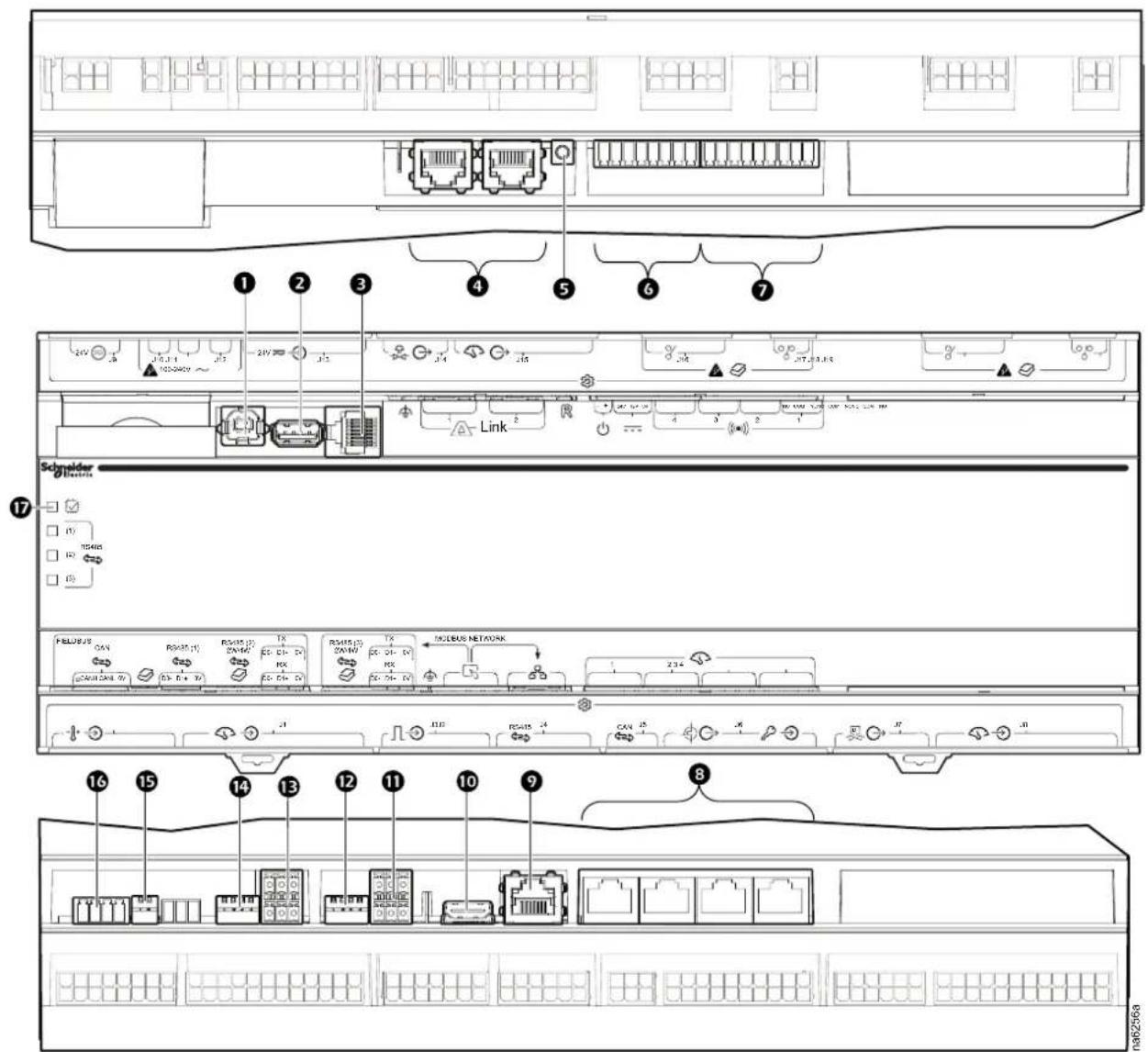
| Item | Description | Item | Description |
| 1 | USB device port | 10 | Touch screen display connection |
| 2 | USB host port (Not available) | 11 | Modbus connection |
| 3 | Serial port (Not available) | 12 | Modbus configuration switches |
| 4 | A-Link ports | 13 | Fieldbus Modbus connection (Not available) |
| 5 | Reset button | 14 | Fieldbus Modbus configuration switches (Not available) |
| 6 | Output relay 4/standby input | 15 | Fieldbus CANbus configuration switches |
| 7 | Output relay 1–3 | 16 | Fieldbus CANbus connection |
| 8 | Universal sensor ports | 17 | Processor status LED |
| 9 | Network connection |
A-Link Connections
NOTE: All input and output connections should be wired as Class 2 circuits.
The A-Link bus connection allows a maximum group of twenty (20) Uniflair InRow ACRD30X units to communicate with each other.
To enable the units to function as a group, link them together using a standard pin-out CAT-5 cable with RJ-45 connectors. The A-Link bus must be terminated at the first and last unit installed in the group. An A-Link terminator is supplied with each unit.
NOTICE
CAT 5 PINOUT
Devices connected on the A-Link ports should use a standard pin-out (1-1, 2-2, 3-3, 4-4, 5-5, 6-6, 7-7, 8-8) CAT5 cable only.
Failure to follow these instructions can result in equipment damage.
NOTE: The maximum wire length for the entire group must not exceed 500 m (1640 ft).
Active Flow Controllers (AFC)
If AFC units are installed in the cooling group in a HACS or CACS environment, they are connected to the A-Link bus as shown. If the cooling group is in an under floor environment, the AFC unit is connected through the J5 port on the controller.

See the AFC Installation Manual for more information.
Control the Environment
The primary function of the cooling unit is to cool air from the hot aisle and deliver it to the cold aisle at the temperature setpoint. The control strategies employed by the cooling unit depend upon the deployment strategy of the cooling group.
In an InRow environment, the cooling unit supplies constant-temperature supply air to the common cold aisle. The fan speed is modulated to ensure that the desired volume of air reaches the IT equipment. The fan speed is determined by the difference between the cooling setpoint and the maximum rack air inlet temperature.
In a HACS or RACS environment, the cooling unit neutralizes the heat accumulated in the common hot aisle and expels it back into the surrounding environmental space while maintaining the desired temperature in the cold aisle.
In a CACS environment, the cooling unit supplies constant temperature supply air to the enclosed cold aisle. The fan speed is modulated to ensure that the required volume of air reaches the IT equipment.
How the Modes of Operation Work
Path: Main > Configuration > Group > Cooling
Path: Main > On/Off
NOTE: The Cooling Strategy settings in both menus are the same settings.
The cooling control varies based on the Cooling Strategy setting.
- Cooling Strategy: The cooling unit uses a direct-expansion coil and a variable-speed compressor to modulate refrigerant flow through the coil, and a set of fans to control airflow through the coil. The cooling output is determined by the difference between the supply setpoint and the supply air temperature of the cooling unit.
INROW: The fan speed is controlled by comparing the rack inlet temperature to the cooling setpoint. As the rack temperature increases compared to the cooling setpoint the fans increase output to maintain the setpoint. As rack inlet temperature decreases compared to the cooling setpoint the fans decrease output to maintain the setpoint.
RACS/HACS: When Active Flow Controller (AFC) devices are present, the controller utilizes differential pressure data supplied by the AFC(s) to supply the correct amount of airflow to the IT load. When AFC devices are not present, the fan speed is controlled by the fan speed preference setting. The fan speed selection is based on the temperature differential detected across the cooling unit. As return temperatures deviate from the fan speed preference setting, the fan speed increases to bring the temperature difference back down to the setpoint or the fan output is reduced to increase the unit temperature differential. By maintaining the desired temperature differential, the system matches the airflow requirements of the load.
CACS: When AFC devices are present, the controller utilizes differential pressure data supplied by the AFC(s) to supply the correct amount of airflow to the IT load. When AFC devices are not present, the evaporator fan speed is controlled by comparing the rack inlet temperature to the cooling setpoint. As the rack temperature increases compared to the cooling setpoint, the fans output is increased to maintain the setpoint. As rack temperature decreases compared to the cooling setpoint the fans output is decreased to maintain the setpoint.
- Manual: The fan speed is controlled by the user-input value for Manual IT Fan Speed.
The cooling unit is equipped with compressor cycling control that allows for minimizing the number of compressor on and off cycles. The compressor will cycle off when the supply air temperature drops below 13^ C ( 55.4^ F) whether or not the compressor minimum on-time of three minutes has elapsed. Once off, the compressor will not normally cycle on until the supply temperature reaches its setpoint and the minimum off-time of two minutes has elapsed. However, the
compressor will cycle on disregarding the off-time if it is a standalone unit or if the unit is power cycled, the compressor will cycle on regardless of whether or not the minimum off time has elapsed (InRow and CACS only).
Compressor cycles are monitored over a seven-day period. If over said period the number of cycle is more than 12 per hour on average, the Excessive Compressor Cycling alarm is set.
Setpoints
A setpoint is the target value that a cooling group tries to maintain in the environment. The default setpoints are appropriate for most cooling applications.
NOTE: Changing the settings incorrectly can cause malfunctions to your cooling unit. Only qualified service personnel should make changes to these settings.
NOTE: Displayed settings may vary based on model and unit configuration.
Path: Main > Configuration > Group > Cooling
- Cooling Strategy: Select the cooling strategy used to control the operation of the unit. (RACS, HACS, INROW, CACS, Manual)

See the How the Modes of Operation Work, page 39 for more information on the types of cooling strategy.
- Supply Air Setpoint: The Supply Air Setpoint is the required temperature of the air expelled into the surrounding environment. (15.0–30.2°C (59.0–86.4°F))
NOTE: The Supply Air Setpoint is defined by Schneider Electric qualified personnel when the cooling group is commissioned.
- Cool Setpoint: Set the temperature that the cooling group should maintain in the IT space. (17.8–35.0°C (64.0–95.0°F))
- Delta-T Setpoint: When the group is programmed for HACS or RACS mode, this value specifies the desired temperature difference between the supply and return air temperatures when an AFC is not present. (10F/5.6C, 15F/8.3C, 20F/11.1C, 25F/13.9C, 30F/16.7C, 35F/19.4C, 40F/22.2C)
NOTE: Set a lower Cool Setpoint or a smaller Delta-T Setpoint to assist with start-up during winter.
- Load Assist Enable: When set to Enable, provides extra capacity via a backup cooling unit in the event that a primary unit is unable to service the demand. When the assistance is no longer needed, the unit will return to the backup state.
NOTE: Redundancy (backup units), runtime balancing, and load assist modes are only supported in HACS, RACS, and CACS configurations.
- Runtime Balancing Enable: When set to Enable, the system maintains similar run times between units in the group. When the difference between the runtime hours of the cooling units in the system exceeds the value entered for Runtime Balancing Difference, the system will automatically exchange modes between the longest running primary unit and the backup unit with equal or greater capability if available with the least runtime hours.
NOTE: The runtime balancing cap is not adjustable. Runtime hours are the hours in which the cooling unit is actually operating and NOT 72 consecutive hours (three days) of time.
- Runtime Balancing Difference: Enter the number of hours used to maintain runtime balancing in the cooling group. (24–720 hours)
- Switchover Handoff Time: Enter the length of time that the currently active unit will remain on after another unit is made the active unit. Both units will be running during this time. (0–30 minutes)
- Humidification Setpoint: The target value for the relative humidity of conditioned air, as a percentage. The Humidification Setpoint must be at least 5% RH below the Dehumidification Setpoint. (0-100%)
NOTE: Available for ACRH301P units only.
- Dehumidification Setpoint: The target value for the relative humidity of conditioned air, as a percentage. The Humidification Setpoint must be at least 5% RH below the Dehumidification Setpoint. (0-100%)
NOTE: Available for ACRH301P units only.
- Humidity Hysteresis: Enter the hysteresis value for humidity, which is the humidity percentage below the setpoint at which humidification is permitted. (0-20%)
NOTE: Available for ACRH301P units only.
- Reheat Setpoint: The target value for air leaving the cooling unit. This setting must be at least 2°F (1.1°C) below the Supply Air Setpoint. (10–15°C (50–59°F))
NOTE: Available for ACRH301P units only.
Active Flow Controller (AFC) Settings
Path: Main > Configuration > Containment Systems
- Number of Active Flow Controllers: Set the number of Active Flow Controller units in the group. (0–5)
• Active Flow Control Lamp Test: When set to On, the Active Flow Controller (s) LEDs will cycle through a red, green, and blue illumination pattern. - Active Flow Control Bias: This setting is used to change the bias of the controller by adjusting the contained aisle pressure threshold. Zero is the default setting. Only qualified service personnel can make changes to these settings.
Hot Aisle Containment (HACS)
- If the cooling units seem to be under-cooling, select Negative or Slightly Negative to adjust the aisle pressure for additional cooling.
- If the cooling units seem to be over-cooling, select Positive or Slightly Positive to adjust the aisle pressure for less cooling.
- Cold Aisle Containment (CACS)
- If the cooling units seem to be under-cooling, select Positive or Slightly Positive to adjust the aisle pressure for additional cooling.
- If the cooling units seem to be over-cooling, select Negative or Slightly Negative to adjust the aisle pressure for less cooling.
| Setting Blue LED—HACS | Red LED—CACS | Setpoint Green LED | Red LED—HACSBlue LED—CACS |
| Positive | < -0.008 in. ±3% | 0.004 ±0.0004 in. | > 0.016 in. ±3% |
| Slightly Positive < -0.010 in. ±3% 0.002 ±0.0004 in. > 0.014 in. ±3% | |||
| Zero | < -0.012 in. ±3% | 0.000 ±0.0004 in. | > 0.012 in. ±3% |
| Slightly Negative < -0.014 in. ±3% -0.002 ±0.0004 in. > 0.010 in. ±3% | |||
| Negative | < -0.016 in. ±3% | -0.004 ±0.0004 in | > 0.008 in. ±3% |
Run Hours and Service Intervals
Run Hours
The cooling unit records the number of hours in which the selected components have been operating. When a component is replaced, use the Run Hours Reset menu to reset the run hours for the displayed component to zero. These settings are read-only values.
Path: Main > Status > Hours
- Unit Run Hrs
• Air Filter Run Hrs - Compressor Run Hrs
• Condenser Fan Run Hrs - Condensate Pump Run Hrs
- Fan 1 Run Hrs
- Fan 2 Run Hrs
- Fan 3 Run Hrs
- Fan 4 Run Hrs
- Fan 5 Run Hrs
- Fan 6 Run Hrs
- Fan 7 Run Hrs
• Fan 8 Run Hrs
• Humidifier Run Hours - Heater 1 Run Hours
• Dry Cooler Run Hrs
• Heater 2 Run Hours
NOTE: Fan 1 is the bottom fan; fan 8 is the top fan.
NOTE: Condenser Fan Run Hrs will be shown only when Coil Type is set as Twin Cool, and the Twin Cool Select is set as DX.
Run Hours Settings
Path: Main > Configuration > Service > Run Hours
Settings under this menu are used to reset the run hour alarms that are configured as reminders for regular maintenance inspection.
Select Enable/Disable and press OK to enable or disable the run hours alarms for an individual component.
Set Weeks and press OK to set the run hours for an individual component.
Select Reset and press OK to reset the run hours for an individual component. The following components can have run hour alarms set:
- Unit Alarm Enabled
- Unit Alarm Reset
- Unit Alarm Interval
• Air Filter Alarm Enabled
• Air Filter Alarm Reset
• Air Filter Alarm Interval - Compressor Alarm Enabled
- Compressor Alarm Reset
- Compressor Alarm Interval
• Dry Cooler Fan Alarm Enabled
• Dry Cooler Fan Alarm Reset
• Dry Cooler Fan Alarm Interval
- Condensate Pump Alarm Enabled
- Condensate Pump Alarm Reset
- Condensate Pump Alarm Interval
• Condenser Fan Alarm Enabled
• Condenser Fan Alarm Reset
• Condenser Fan Alarm Interval
• Fan 1 Alarm Enabled
- Fan 1 Alarm Reset
• Fan 1 Alarm Interval
• Fan 2 Alarm Enabled
- Fan 2 Alarm Reset
- Fan 2 Alarm Interval
• Fan 3 Alarm Enabled
- Fan 3 Alarm Reset
• Fan 3 Alarm Interval
• Fan 4 Alarm Enabled
- Fan 4 Alarm Reset
• Fan 4 Alarm Interval
• Fan 5 Alarm Enabled
- Fan 5 Alarm Reset
• Fan 5 Alarm Interval
• Fan 6 Alarm Enabled
- Fan 6 Alarm Reset
• Fan 6 Alarm Interval
• Fan 7 Alarm Enabled
- Fan 7 Alarm Reset
• Fan 7 Alarm Interval
• Fan 8 Alarm Enabled
- Fan 8 Alarm Reset
• Fan 8 Alarm Interval
• Humidifier Alarm Enabled
• Humidifier Alarm Reset
• Humidifier Alarm Interval
• Heater 1 Alarm Enabled
- Heater 1 Alarm Reset
• Heater 1 Alarm Interval
- Heater 2 Alarm Enabled
- Heater 2 Alarm Reset
• Heater 2 Alarm Interval
Service Intervals
Path: Main > Configuration > Unit > Alarms > Maintenance
Each component interval setting has an alarm. If set to Enable, the annunciator will sound when the service interval for the component has elapsed. The alarms
are cleared by selecting the check box for the XXX Alarm Reset for each component to reset the service alarm and pressing OK. Enable service interval alarms and set the number of weeks to service the following components:
- Unit Run Hours: Displays the total hours the unit has been in operation.
- Unit Alarm Enabled: Select to Enable or Disable the alarm.
- Unit Alarm Reset: Select Reset and press OK to reset the run hours for an individual component.
- Unit Alarm Interval: Set the interval for the service alarm for the cooling unit. (1–300 wk)
• Air Filter Run Hrs: Displays the number of hours the filters have been in use.
• Air Filter Alarm Enabled: Select to Enable or Disable the alarm. - Air Filter Alarm Reset: Select Reset and press OK to reset the run hours for the air filter.
- Air Filter Alarm Interval: Set the interval for the service alarm for the air filters. (1–300 wk)
User Security Settings
The Security menus under the Display menu include options for user access to the unit.
Add a New User or Edit an Existing User
Path: Main > Configuration > Display > Security
- Select Add User to add a new user or select Edit User to edit an existing user of the system.
- In the Name field, enter the name of the user.
- In the Pin field, enter a pin code for the user.
- In the Confirm Pin field, re-enter the pin code of the user.
- Press OK to save your settings.
Delete a User
- Browse to the user that you wish to delete using the up and down arrows and press OK.
- Press Yes to confirm deletion of an existing user of the system.
Display Settings
The Display menus set the display interface settings, including time and date, units, passwords, and time-out. You can also adjust the contrast and sound settings.
Language, Date, Time, and Temperature
- Language: Select the correct language for the display.
- Date Format: Select the display format for the date.
• Temperature: Select Metric or US Customary for temperature format. - Manual: Manually enter the current and time instead of retrieving from a server.
- Current Date: Enter the day, month, and year. The date is displayed on some status screens and is also used in the alarm/event log to date-stamp events.
- Current Time: Enter the current time for the display.
- Synchronize with NTP Server: Select to sync the time and date with the Network Time Protocol server.
Screen Visibility and Audible Tones
- Alarm Volume: Select the level of audio at which alarms will sound (Off, Low, Medium, or High).
- Button Volume: Select the volume at which a tone will be produced every time a button is pressed on the display interface. The audible tone can also be set to Off.
- Brightness: Controls the visibility of the display.
- Enable Backlight Timeout: Enable or Disable backlight timeout settings.
- Backlight Timeout: Adjust the backlight timeout settings.
Minutes: Turns off unit backlight after a specified amount of time. Timeout range is 1–60 minutes. - Intensity: Select the visibility of the display during backlight timeout.
- Off: The display will remain at the normal intensity level.
- Very Low: The display will be very dim.
- Low: The display will be dim.
- Medium: The display will dim to about half of the normal brightness.
- Auto Logoff: Automatically signs current user out of the system after specified amount of time. Options are 1, 5, 10, 30, or 60 minutes.
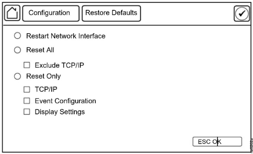
Restore Defaults
Path: Main > Configuration > Restore Defaults
The Restore Defaults screen is used to restart the display and reset display settings to factory defaults.
NOTE: The controller settings will not be restored.
Network Configuration
The cooling unit is shipped with a Network Management Card (NMC) that enables you to manage the cooling unit over your network. Configure the network settings for the cooling unit Network Management Card from the display interface. The management card allows remote control and configuration of the equipment.
Configure the Network
TCP/IPv4 Settings
Path: Main > Configuration > Network > TCP/IPv4
Enable IPv4 (if applicable), and select the Address Mode (Manual, DHCP, BOOTP).
- Manual: Enter the IP Address, subnet mask, and default gateway.
- BootP: Set the Network Management Card of the cooling unit to obtain its network settings from a BootP server.
- DHCP: Set the Network Management Card of the cooling unit to obtain its network settings from a DHCP server. Select whether or not to require vendor-specific cookies to accept the DHCP address.
TCP/IPv6 Settings
Path: Main > Configuration > Network > TCP/IPv6
Enable IPv6 (if applicable).
- Select Auto Configuration or Manual Configuration, and select the DHCPv6 Mode (Router Controlled, Non-Address Information Only, Address and Other Information, or Never).
- For Manual Configuration, enter the System IP and Default Gateway.
Web Access Settings
Path: Main > Configuration > Network > Web Access
Enable Web (if applicable) and select the Access Mode (HTTP or HTTPS) and enter the Port.
FTP Server Settings
Path: Main > Configuration > Network > FTP Server
Enable FTP (if applicable) and enter the Port.
View Status Readings
The display interface has several options for viewing the status of the cooling unit, the cooling group to which the cooling unit belongs, and the environment being controlled. The status readings for the cooling unit are available under the Status > Unit screen, and status readings for the cooling group are available under the Status > Group Status screen or on the overview screen.
Overview Screen
After start-up, the display shows an overview screen containing basic status information. Press Home to toggle between the main menu and overview screen. After a period of inactivity, the display also reverts back to the overview screen.
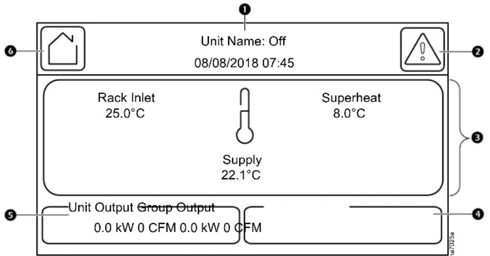
Item Description
Unit operational status and current date and time
Alarms button
- Rack Inlet: The average reading from rack inlet temperature sensors connected to this unit. This is displayed when the Cooling Strategy is set to INROW, CACS, or Manual.
- Return Temp: The return air temperature reading. This is displayed when the Cooling Strategy is set to HACS or RACS.
- Superheat: The superheat reading for this unit: the temperature difference between refrigerant entering and leaving the coil.
• Supply: The average temperature from the top and bottom supply air temperature sensors connected to this unit.
4 The total cooling output and airflow of all units in the cooling group.
5 The cooling output and airflow of this unit.
6 Home button
Cooling Unit Status
Path: Main > Status > Unit
View information specific to this cooling unit.
NOTE: These are read-only values.
- Mode: Displays the current operational mode of the unit.
Unknown: A status cannot be currently acquired.
- Init: Unit is currently initializing.
- Off: Unit is currently off.
Standby: Unit is in standby mode.
- Delaying: Unit is delaying start until the Startup Delay time has elapsed.
• Active: Unit is currently cooling.
- Supply (Average) Temperature: The average temperature from the top and bottom supply air temperature sensors connected to this unit. (°C (°F))
- Maximum Rack Inlet Temperature: The average reading from rack inlet temperature sensors connected to this unit. (°C (°F))
- Return (Average) Temperature: The average temperature from the top and bottom return air temperature sensors connected to this unit. (°C (°F))
• Humidity: The current relative humidity of the IT room. (%RH) - Airflow: The current airflow output of the unit. (Vsm)ift
• Air Filter Pressure: The current air pressure at the air filter. (Pa (in. WC)) - Cool Demand: The cooling output required to meet the current heat load of the conditioned space. (kW)
- Cool Output: The combined output of the cooling unit. (kW)
• Fan 1: The speed of IT Fan 1.
• Fan 2: The speed of IT Fan 2.
• Fan 3: The speed of IT Fan 3.
• Fan 4: The speed of IT Fan 4.
• Fan 5: The speed of IT Fan 5.
• Fan 6: The speed of IT Fan 6.
• Fan 7: The speed of IT Fan 7.
• Fan 8: The speed of IT Fan 8. - Chilled Water Inlet Temperature: The water inlet temperature.
- Choke Valve Position: The position of the choke valve which is connected to the economizer coil.
- Bypass Valve Position: The position of the bypass valve which is connected to the plate heat exchanger.
- Dry Cooler Fan Speed: The speed of dry cooler fan which is connected to this unit.
Cooling Group Status
Path: Main > Status > Group Status
View information specific to this cooling group.
NOTE: These are read-only values.
- Group Minimum Rack Temperature: The lowest rack temperature reported by any cooling unit in the cooling group. (°C (°F))
- Group Maximum Rack Temperature: The highest rack temperature reported by any cooling unit in the cooling group. (°C (°F))
- Group Dew Point Temperature: The average group dew point temperature. (°C (°F))
- Total Airflow: The combined airflow output of the cooling units in the cooling group. (l/s (₹m))
- Total Air Side Cooling Demand: The cooling output required to meet the current heat load of the conditioned space. (kW)
- Total Sensible Cooling Power: The combined output of the cooling group. (kW)
- Active Flow Control Status: The conditional state of the containment air pressure differential measurement device (AFC).
Under: The air flow status on at least one AFC unit is insufficient. The LED on the AFC will be illuminated as red. - OK: There is nominal air flow status on all AFC units. The LED on the AFC will be illuminated as green.
Over: There is a surplus of air flow status on at least one AFC unit. The LED on the AFC will be illuminated as blue. - NA: There are no AFC units installed or no status reading is available.

See Active Flow Controller (AFC) Settings, page 42 for information on adjusting the Active Flow Control Bias.
Sensor Readings
Path: Main > Status > Details > Environment
The Environment menu provides the readings from sensors connected to the unit.
- Upper Supply Temperature: The temperature from the top supply air temperature sensor connected to this unit. (°C (°F))
- Lower Supply Temperature: The temperature from the bottom supply air temperature sensor connected to this unit. (°C (°F))
- Upper Return Temperature: The temperature from the top return air temperature sensor connected to this unit. (°C (°F))
- Lower Return Temperature: The temperature from the bottom return air temperature sensor connected to this unit. (°C (°F))
- Room Temperature: The temperature of the ambient air in the IT space. (°C (°F))
- Humidity: The relative humidity of the air in the IT space. (%RH)
- Dew Point Temperature: The dew point of the IT space. (°C (°F))
- Rack Inlet Temperature 1: The temperature from the rack inlet 1 air temperature sensor connected to this unit. (°C (°F))
-
Rack Inlet Temperature 2: The temperature from the rack inlet 2 air temperature sensor connected to this unit. (°C (°F))
-
Rack Inlet Temperature 3: The temperature from the rack inlet 3 air temperature sensor connected to this unit. (°C (°F))
- Rack Inlet Temperature 4: The temperature from the rack inlet 4 air temperature sensor connected to this unit. (°C (°F))
Refrigerant System
Path: Main > Status > Details > DX
The DX menu provides information for the refrigerant system components and pressure and temperature readings.
NOTE: These are read-only values.
- Suction Pressure: The pressure of the refrigerant at the suction line. (bar (psi))
- Discharge Pressure: The pressure of the refrigerant at the discharge line. (bar (psi))
- Suction Evap. Temp.: The temperature of the refrigerant at the suction line. (°C (°F))
- Discharge Cond. Temp.: The temperature of the refrigerant at the discharge line. (°C (°F))
- Outlet Evap Coil Temperature: The temperature of the refrigerant leaving the evaporative coil. (°C (°F))
- Inlet Evap Coil Temperature: The temperature of the refrigerant entering the evaporative coil. (°C (°F))
- Superheat: The temperature difference required to keep the refrigerant in a gaseous state. (Δ°C (Δ°F))
• Avg Fan Speed: The current average speed of the eight fans in the unit. (%) - Compressor Speed: The current speed of the compressor. (Hz)
- EEV Position: The current open percentage of the electronic expansion valve. (%)
- Condenser Fan Speed: The current speed of the condenser fan (it will be shown only when Coil Type is set as Twin Cool and the Twin Cool Select is set as DX). (%)
Power Information
Path: Main > Status > Details > Power
The Power menu provides power consumption information for components in the unit.
NOTE: These are read-only values.
- Power Feed Type: Displays whether the indoor unit has a Single or Dual power feed.
- Active Power Source: Displays if the unit is using the primary or secondary power source.
- Primary Power Source: If the power source is Bad, then the ATS will transfer to the secondary power supply.
- Secondary Power Source: If the secondary power source is good, then it can be used in the event of primary source is bad.
- Fan Power Supply 1: The current draw of fan power supply 1. (A)
- Fan Power Supply 2: The current draw of fan power supply 2. (A)
- Condenser Fan Power: The power of condenser fan. (W)
- Compressor Power: The current draw of the compressor. (kW)
Input/Output States
Path: Main > Status > Details > Input/Output
The Input/Output menu provides the current state of input/output connections.
NOTE: These are read-only values.
- Shutdown Input State: The current state of the shutdown input. (Open or Closed)
• Alarm Relay 1: The current state of alarm relay 1. (Open or Closed) - Alarm Relay 2: The current state of alarm relay 2. (Open or Closed)
• Alarm Relay 3: The current state of alarm relay 3. (Open or Closed)
• Alarm Relay 4: The current state of alarm relay 4. (Open or Closed)
About the Network
View identifying information about the cooling network parameters (IPv4 or IPv6).
Path: Main > About > Network
IPv4 Configuration: If IPv4 is used, this section will display IPv4 information.
- Enabled: Identifies whether the specified network is enabled or not.
- Mode: Identifies how the IP address is obtained.
- IP Address: The IP address of the unit.
- Subnet Mask: The subnet mask for the sub-network.
- Default Gateway: The default gateway address used by the network.
IPv6 Configuration: If IPv6 is used, this section will display IPv6 information.
Press Addresses to view all assigned IPv6 addresses.
- Enabled: Identifies whether the specified network is enabled or not.
- Auto Configuration: Displays Yes if the IP address is assigned automatically.
- Manual Configuration: Displays Yes if the IP address is assigned manually.
- DHCPv6 Mode: The DHCPv6 mode.
- Router Controlled: DHCPv6 is controlled by the M (Managed Address Configuration Flag) and O (Other Stateful Configuration Flag) flags received in IPv6 Router Advertisements. When a router advertisement is received, the network management card (NMC) checks whether the M and O flags are set. The NMC interprets the state of the M and O "bits" for the following cases:
- Neither is set: Indicates local network has no DHCPv6 infrastructure. The NMC uses Router Advertisements and/or manual configuration to get non-link-local addresses and other settings.
- M, or M and O are set: In this situation, full DHCPv6 address configuration occurs. DHCPv6 is used to obtain addresses AND other configuration settings. This is known as DHCPv6 stateful. Once the M flag has been received, the DHCPv6 address configuration stays in effect until the interface in question has been closed, even if subsequent Router Advertisement packets are received in which the M flag is not set. If an O flag is received first, then an M flag is received subsequently, the NMC performs full address configuration upon receipt of the M flag.
- Only O is set: In this situation, the NMC sends a DHCPv6 Info-Request packet. DHCPv6 is used to configure "other" settings (such as location of DNS servers), but NOT to provide addresses. This is known as DHCPv6 stateless.
- Address and Other Information: DHCPv6 is used to obtain addresses AND other configuration settings. This is known as DHCPv6 stateful.
- Non-Address and Information Only: DHCPv6 is used to configure "other" settings (such as locations of DNS servers), but NOT to provide addresses. This is known as DHCPv6 stateless.
Never: If this radio box is selected, DHCPv6 is NOT to be used for any configuration settings.
About the Unit
View identifying information that is helpful when obtaining service.
NOTE: Displayed settings are read-only and will vary based on unit type and configuration.
Path: Main > About > Unit
- Model Number: The model number of the unit.
- Serial Number: The serial number of the unit.
- Firmware Revision: The firmware revision of the unit.
- Development Firmware Revision: The developmental firmware revision of the unit.
- Hardware Revision: The hardware revision of the unit.
- Manufacture Date: The date the cooling unit was manufactured.
- PIC1 Firmware Revision: The firmware revision of the PIC1 processor.
- PIC2 Firmware Revision: The firmware revision of the PIC2 processor.
About the AFC
Path: Main > About > AFC
View information about the Active Flow Controller units in the cooling group.
- Serial Number: The serial number of the AFC.
- Firmware Revision: The firmware revision of the AFC.
- Hardware Revision: The hardware revision of the AFC.
- Model Number: The model number of the AFC.
- Lamp Test Enable: Select the check box and press OK to test the LED on the AFC. The LED will cycle through a red, green, blue illumination pattern until the user stops the test. To stop the LED test, deselect the check box and press OK.
About the Display
Path: Main > About > Display > Device
Device summary: Information about the physical display device.
- Model Number: The model number of the display interface.
- Serial Number: The serial number of the display interface.
- Hardware Revision: The hardware revision of the display interface.
- Manufacture Date: The date the display interface was manufactured.
- MAC Address: The MAC address of the unit.
Path: Main > About > Display > Firmware
Firmware summary: View identifying revision information about the display interface firmware:
- Application
- APC OS (AOS)
- APC Boot Monitor
- Video Driver
- FPGA
Logs
Event Log
The Event Log saves status information and a message each time a change in the unit is detected. Alarms and events are recorded in the log and displayed on the Active Alarms screen. Status events (informational) and system configuration changes are only displayed in the event log.
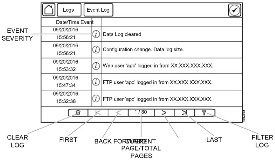
View Event Log
Path: Main > Logs > Event Log
The Event Log keeps a record of all alarms and events. The screen displays the following:
• The name of the event.
• The severity of the event.
• The time and date the event occurred.
Use the arrows to scroll through the list of events and display the date and time for each event.
Filter Event Log
Events in the Event Log can be sorted by time or severity. Events can also be displayed by Device Events or System Events. Press ESC to return to the previous screen without making changes; press OK to accept changes.
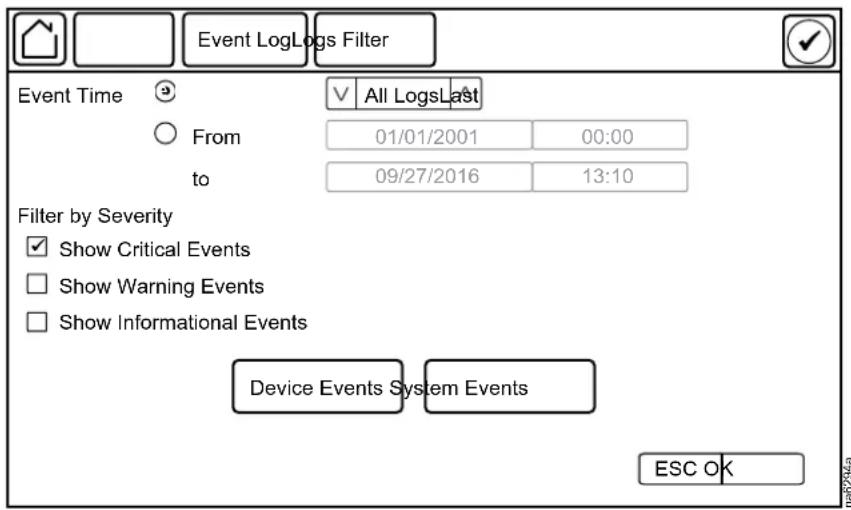
The filter options for related Device Events are the following:
- Communication
- Temperature
- Fans
- Status
- Diagnostics
- Humidity
- Configuration
The filter options for related System Events are the following:
- Mass Configuration
- Security
Clear Event Log
Path: Main > Logs > Event Log
- Press the trash can icon in the bottom-left corner of the Event Log screen to clear the log. A confirmation screen is displayed.
- Enter the Admin password to clear the log.
- Select Yes to clear all of the events in the log. Select No to return to the Event Log screen.
Data Log
Path: Main > Logs > Data Log > Graphing
The Data Log is a graph showing the changes over time of selected readings. Select the data point to graph and press + to add the data point to the graph. To remove a data point from the graph, select the data point from the list and press - To clear the graph, press CLR.
NOTE: Image is an example only; your screen may differ.
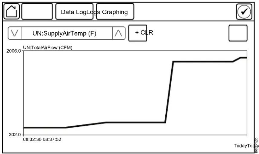
line
| Time | TotalAirFlow (CFM) | | ---------- | ------------------ | | 08:32:30 | 302.0 | | 08:37:52 | 302.0 | | Current | 2006.0 |Data Log Configuration
Select at what intervals (Log Interval) the data log will record an entry. When the size of the data log reaches the Data Log Size entry limit, the log will overwrite itself by deleting the first half of the data and continuing recording as normal.
![Data LogLogs Graphing Log Interval: [1 min - 18 hrs 12 mins] hrs mins secs Data Log Size: [25 - 1500] ESC OK](/content/2026/05/1008427/images/b5aa69db87edeeabac1e868b4dd4b880f7d47365fd61099c6f541dda3ae535d6.jpg)
Export Data
Path: Main > Logs > Export Data
The data export function exports a .tar file containing the following files:
- config.ini
- data.txt
- debug.txt
-
event.txt
-
Insert a USB drive into the USB port of the display interface.
- Press Start Data Export.
- Confirm exporting the data to the USB drive.
- Wait for the data to export or abort exporting by pressing Abort Data Export.
- Press OK when the "Data exported successfully. Remove USB device." message displays.
- Remove the USB drive from the display interface.
Alarms
Respond to Alarms
When an alarm is triggered, the unit alerts you through the display by the following methods:
• LEDs on the display interface
- Alarm icon in the upper-right corner of the screen
- An optional audible alarm every 30 seconds if enabled
View Active Alarms
The Active Alarms screen is accessed by pressing the alarm icon in the upper-right corner of the screen. The Active Alarms screen provides the number of alarms, the severity, and a brief description of the alarm.
Clear Active Alarms
- Press Clear to clear the active alarms.
A confirmation screen is displayed. - Enter the Admin password to erase the alarms list.
- Select Yes to erase all of the alarms. Select No to return to the Active Alarms screen.
Alarm Thresholds
Path: Main > Configuration > Unit > Alarms > Thresholds
Thresholds can be set to activate alarms to alert you to violations when the threshold is exceeded.
- Supply Air High Temperature Threshold: The high temperature threshold for the supply air as averaged by the supply air temperature sensors. If the temperature exceeds this threshold, an alarm will occur. (0–100°C (32–212°F))
- Rack Inlet High Temperature Threshold: The high temperature threshold for the rack inlet air temperature as averaged by the rack inlet temperature sensors. If the temperature exceeds this threshold, an alarm will occur. (0–100°C (32–212°F))
- Return Air High Temperature Threshold: The high temperature threshold for the air entering the cooling unit. If the temperature exceeds this threshold, an alarm will occur. (0–100°C (32–212°F))
- Return Humidity High Threshold: The relative humidity at which the high threshold alarm occurs. (35–90%RH)
- Return Humidity Low Threshold: The relative humidity at which the low threshold alarm occurs. (20–50%RH)
- Clogged Filter Thresh.: The pressure at which a clogged filter alarm occurs. (24.88–236.40 Pa (0.10–0.95 in. WC))
Alarm Messages and Suggested Actions
| Alarm Message | Severity | Action Required |
| Active Flow Controller Sensor Error | Warning | Contact Schneider Electric Technical Support. |
| AFC Firmware Incompatibility Detected Critical | • Check revision of AFC firmware.• If the problem persists, contact Schneider Electric Technical Support. | |
| Air Filter Clogged | Warning | • Clean or replace the air filter.• If the problem persists, contact Schneider Electric Technical Support. |
| Air Filter Run Hours Exceeded Warning | Reset the Air Filter Run Hours after the air is cleaned or replaced. | |
| Air Filter Pressure Sensor Error | Warning | • Check the sensor connection.• If the problem persists, contact Schneider Electric Technical Support. |
| Condensate Pan Full | Warning | A hardware problem may exist: Contact Schneider Electric Technical Support. |
| Condensate Pan Warning Critical A hardware problem may exist: Contact Schneider Electric Technical Support. | ||
| Condensate Lower Float Error Critical • Check the float switch.• If the problem persists, contact Schneider Electric Technical Support. | ||
| Condensate Pump Error Critical Contact Schneider Electric Technical Support. | ||
| Condenser Communication Error Critical • Check the RS485 connection to the outdoor unit.• Check power to outdoor unit.• If problem persists, contact Schneider Electric Technical Support | ||
| Condenser Fan Mains Over Voltage | Critical Contact Schneider Electric Technical Support. | |
| Condenser Fan Mains Under Voltage | Critical Contact Schneider Electric Technical Support. | |
| Condenser Fan DC Link Over Voltage | Warning | Contact Schneider Electric Technical Support. |
| Condenser Fan DC Link Under Voltage | Warning | Contact Schneider Electric Technical Support. |
| Condenser Fan Electronic Over Heated | Critical Contact Schneider Electric Technical Support. | |
| Condenser Fan Locked Motor | Critical Contact Schneider Electric Technical Support. | |
| Condenser Fan Hall Sensor Error | Critical Contact Schneider Electric Technical Support. | |
| Condenser Fan Motor Overheated | Critical Contact Schneider Electric Technical Support. | |
| Condenser Fan Bad | Critical Contact Schneider Electric Technical Support. | |
| Condenser Fan Communication Error | Critical Contact Schneider Electric Technical Support. | |
| Condenser Fan Power Module Overheated | Critical Contact Schneider Electric Technical Support. | |
| Condenser Fan Phase Error | Critical Contact Schneider Electric Technical Support. | |
| Condenser Fan Cable Break | Critical Contact Schneider Electric Technical Support. | |
| Condenser Fan Low Speed | Critical Contact Schneider Electric Technical Support. | |
| Condenser Fan Brake Operation | Critical Contact Schneider Electric Technical Support. | |
| Condenser Fan DC Link Voltage Low | Warning | Contact Schneider Electric Technical Support. |
filter
| Alarm Message | Severity | Action Required |
| Condenser Fan Electronics Temperature High | Critical Contact | Schneider Electric Technical Support. |
| Condenser Fan Motor Temperature High | Critical Contact | Schneider Electric Technical Support. |
| Condenser Fan Power Limitation Critical Control | Contact Schneider | Electric Technical Support. |
| Condenser Fan Current Limitation Critical Control | Contact Schneider | Electric Technical Support. |
| CPY: EA: Foam Alarm | Warning | Contact Schneider Electric Technical Support. |
| CW Inlet 1 Temp Sensor Failed | Warning | Contact Schneider Electric Technical Support. |
| Discharge Pressure Sensor Error | Warning | Check the sensor connection.If the problem persists, contact Schneider Electric Technical Support. |
| EcoAisle Door Open | Warning | Verify the aisle containment system door is shut properly.If the problem persists, contact Schneider Electric Technical Support. |
| Energy Saver Choke Valve Error Critical Control | Contact Schneider Electric Technical Support. | |
| Evap Coil Freeze Protection Critical Control | Schneider Electric Technical Support. | |
| Evap Fan #s Error Detected | Warning | A hardware problem may exist: Contact Schneider Electric Technical Support. |
| Evaporator Fan Power Supply Error Detected | Critical Contact | Schneider Electric Technical Support. |
| Evaporator Fan Power Supply #s Error Detected | Warning | Contact Schneider Electric Technical Support. |
| Excessive Compressors Cycling Condition | Warning | Contact Schneider Electric Technical Support. |
| EXV Error | Critical Contact | Schneider Electric Technical Support. |
| High Head Pressure | Critical Check condenser for obstructions.If the problem persists, contact Schneider Electric Technical Support. | |
| High Humidity Threshold Exceeded | Critical Contact | Schneider Electric Technical Support. |
| High Return Temperature | Warning | Make sure the Return Air High Temperature Threshold is set correctly in the Main > Configuration > Unit > Alarms > Thresholds menu.If the problem persists, contact Schneider Electric Technical Support. |
| High Superheat | Critical Contact | Schneider Electric Technical Support. |
| High Supply Temperature | Critical Make sure the Supply Air High Temperature Threshold is set correctly in the Main > Configuration > Unit > Alarms > Thresholds menu.If the problem persists, contact Schneider Electric Technical Support | |
| Humidifier (CL) Cylinder Depleted | Warning | Contact Schneider Electric Technical Support. |
| Humidifier (CP) Excessive Scaling | Warning | Contact Schneider Electric Technical Support. |
| Humidifier Cylinder Life | Warning | Contact Schneider Electric Technical Support. |
| Humidifier (E0) Configuration Parameters Corrupt | Warning | Contact Schneider Electric Technical Support. |
| Humidifier (E1) Parameters not Downloaded | Warning | Contact Schneider Electric Technical Support. |
| Humidifier (E2) Backup Memory Error | Warning | Contact Schneider Electric Technical Support. |
| Humidifier (EC) Water Conductivity High | Warning | Contact Schneider Electric Technical Support. |
| Humidifier (EH) Electrode Current High | Warning | Contact Schneider Electric Technical Support. |
| Humidifier Water Loss | Warning | Contact Schneider Electric Technical Support. |
| Humidifier (EP) Steam Flow Low | Warning | Contact Schneider Electric Technical Support. |
| Humidifier (EU) Water Level High | Warning | Contact Schneider Electric Technical Support. |
| Humidifier Communication Error Critical Contact Schneider | Electric Technical Support. | |
| Humidifier Cylinder Life | Warning | Contact Schneider Electric Technical Support. |
| Humidifier Drain Error | Warning | Contact Schneider Electric Technical Support. |
| Idle Due to Error | Critical A hardware problem may exist: Contact Schneider Electric Technical Support. | |
| Inlet Evap Coil Temperature Sensor Error | Warning | Check the sensor connection.If the problem persists, contact Schneider Electric Technical Support. |
| Input Voltage Not Configured | Critical | Check the Voltage setting in the Main > On/Off menu.If the problem persists, contact Schneider Electric Technical Support. |
| Insufficient Airflow | Warning | Verify the air ports are clear of obstructions and there is sufficient cooling capacity for the load.If the problem persists, contact Schneider Electric Technical Support. |
| Internal Communication Error Critical A hardware problem | may exist: Contact Schneider Electric Technical Support. | |
| Leak Detected | Critical • System is configured to enter idle mode when leak has been detected. Identify the source of the leak.If the problem persists, contact Schneider Electric Technical Support | |
| Low Coolant Temperature | Warning | Contact Schneider Electric Technical Support. |
| Low Humidity Threshold Exceeded Warning | Contact Schneider Electric Technical Support. | |
| Lower Return Temperature Sensor Error | Warning | Check the sensor connection.If the problem persists, contact Schneider Electric Technical Support. |
| Low Suction Pressure Critical • Check the air filter and the evaporator for obstructions.If the problem persists, contact Schneider Electric Technical Support. | ||
| Low Superheat Critical Contact Schneider Electric Technical Support. | ||
| Lower Supply Temperature Sensor Error | Warning | Check the sensor connection.If the problem persists, contact Schneider Electric Technical Support. |
| No Backup Units Available Warning | Check to make sure cooling units in the group have the Unit Role Override | |
| setting on theMain > On/Off screen is toAutomaticand that cooling units are available (not in a failed state).Check that theNumber of Backup Unit in theMain > Configuration > GroupCompositionmenu is not set to zero.If the problem persists, contact Schneider Electric Technical Support. | ||
| Off Due to Input Contact | Warning • For | an abnormal condition, check the remote contact switch and wiring for proper operation.For a normal condition, no action required. |
| Outlet Evap Coil Temperature Sensor Error | Warning | Check the sensor connection.If the problem persists, contact Schneider Electric Technical Support. |
| Output Relay #s is Active Informational Informational message only: no action required. | ||
| Output Relay #s Abnormal Critical Contact | Schneider Electric Technical Support. | |
| Persistent High/Low Superheat Critical Contact | Critical Schneider Electric Technical Support. | |
| Persistent High Head Pressure | Critical • Indicates there were four Compressor High Pressure shutdowns in 30 minutes. Alarms must be cleared manually.If the problem persists, contact Schneider Electric Technical Support. | |
| Persistent Low Suction Pressure Critical A | hardware problem may exist: Contact Schneider Electric Technical Support. | |
| PIC #s Firmware Incompatibility Detected | Critical • Check revision of PIC firmware.If the problem persists, contact Schneider Electric Technical Support. | |
| Primary Power Source Unavailable | Warning | Check power source.If the problem persists, contact Schneider Electric Technical Support. |
| Rack Inlet Temperature Sensor Error Detected | Warning | Contact Schneider Electric Technical Support |
| Rack Inlet High Temperature Warning • Make sure the temperature sensor is connected and placed properly.Make sure the Rack Inlet High Temperature Threshold is set correctly in the Main > Configuration > Unit >Alarms > Thresholds menu.If the problem persists, contact Schneider Electric Technical Support. | ||
| Room Humidity Sensor Error Detected | Warning | Check the sensor connection.If the problem persists, contact Schneider Electric Technical Support. |
| Secondary Power Source Unavailable | Warning | Check power source.If the problem persists, contact Schneider Electric Technical Support. |
| Suction Pressure Sensor Error | Warning | A hardware problem may exist: Contact Schneider Electric Technical Support. |
| Suction Pressure Too Low to Start Critical | A hardware problem may exist: Contact Schneider Electric Technical Support. | |
| Unexpected Number of Active Flow Controllers | Warning | Verify physical number of AFC units is set correctly in theMain >Configuration >Service >Containment Systems.If the problem persists, contact Schneider Electric Technical Support. |
| Unexpected Number of Units in Group | Warning | Check group CAN connection.Verify the number of units within the group is correct (Main >Configuration >Group >Composition).If problem persists, contact Schneider Electric Technical Support |
| Unexpected Number of Leak Detectors Present | Warning | Check theNumber of Leak Detectors in Unit setting in the Main >Configuration >Unit >Components menu.If the problem persists, contact Schneider Electric Technical Support. |
| Unexpected Number of Rack Inlet Temperature Sensors Present | Warning | Contact Schneider Electric Technical Support. |
| Unit Run Hours Exceeded Warning | Service the unit.If the problem persists, contact Schneider Electric Technical Support. | |
| Upper Return Temperature Sensor Error | Warning | Check the sensor connection.If the problem persists, contact Schneider Electric Technical Support. |
| Upper Supply Temperature Sensor Error | Warning | Check the sensor connection.If the problem persists, contact Schneider Electric Technical Support. |
| VFD Communication Error Critical • Check | the RS485 connection to the outdoor unit.Check power to outdoor unit.If problem persists, contact Schneider Electric Technical Support | |
| VFD Control Card Over Temperature Critical | Contact Schneider Electric Technical Support. | |
| VFD Control Card Over Temperature Warning | Warning | Contact Schneider Electric Technical Support. |
| VFD Control Voltage Overloaded | Warning | Contact Schneider Electric Technical Support. |
| VFD Current Limit Exceeded | Warning | Contact Schneider Electric Technical Support. |
| VFD Current Overload Critical Contact Schneider Electric | Technical Support. | |
| VFD Current Overload Warning | Warning | Contact Schneider Electric Technical Support. |
| VFD DC Link Voltage High | Warning | Contact Schneider Electric Technical Support. |
| VFD DC Link Voltage Low | Warning | Contact Schneider Electric Technical Support. |
| VFD DC Overvoltage Critical Contact Schneider Electric | Technical Support. | |
| VFD DC Overvoltage Warning | Warning | Contact Schneider Electric Technical Support. |
| VFD DC Undervoltage Warning | Warning | Contact Schneider Electric Technical Support. |
| VFD Drive Initialized To Defaults Critical | Contact Schneider Electric Technical Support. | |
| VFD Earth Fault | Critical Contact | Schneider Electric Technical Support. |
| Compressor High Head Pressure Switch Tripped | Critical Contact | Schneider Electric Technical Support. |
| VFD Inrush Error | Critical Contact | Schneider Electric Technical Support. |
| VFD Internal Error | Critical Contact | Schneider Electric Technical Support. |
| VFD Drive Initialization Error | Critical Contact | Schneider Electric Technical Support. |
| VFD Mains Phase Loss | Critical Contact | Schneider Electric Technical Support. |
| VFD Motor Over Temperature Critical Contact | Schneider Electric Technical Support. | |
| VFD Motor Phase U Missing | Critical Contact | Schneider Electric Technical Support. |
| VFD Motor Phase V Missing | Critical Contact | Schneider Electric Technical Support. |
| VFD Motor Phase W Missing | Critical Contact | Schneider Electric Technical Support. |
| VFD Motor Thermistor Over Temperature Critical Contact | Schneider Electric Technical Support. | |
| VFD Peak Over Current Critical Contact Schneider Electric Technical Support. | ||
| VFD Persistent Trips | Critical Contact | Schneider Electric Technical Support. |
| VFD Power Card Temperature Critical Contact Schneider Electric Technical Support. | ||
| VFD Short Circuit Critical Contact Schneider Electric Technical Support. | ||
| VFD Speed Not Within Limits | Warning | Contact Schneider Electric Technical Support. |
| VFD Torque Limit Exceeded | Critical Contact | Schneider Electric Technical Support. |
| VFD VDD1 Supply Voltage Low Critical Contact Schneider Electric Technical Support. | ||
Network Management Card
Quick Configuration
The unit is shipped with a Network Management Card that enables the unit to be managed over a network. Configure the Network Management Card to control this unit through a network.
Overview
You must configure the following TCP/IP settings before the Network Management Card can operate on a network:
• IP address of the Network Management Card
- Subnet mask
- Default gateway
NOTE: Never use the loopback address (127.0.0.1) as the default gateway address for the Network Management Card. Doing so will disable the card and will require you to reset TCP/IP settings to their defaults using a local serial login.
NOTE: If a default gateway is unavailable, use the IP address of a computer that is located on the same subnet as the Network Management Card and that is usually running. The Network Management Card uses the default gateway to test the network when traffic is very light.

See “Watchdog Features” in the “Introduction” of the User Manual or Online Guide for more information about the watchdog role of the default gateway.
TCP/IP Configuration Methods
Use one of the following methods to define the TCP/IP settings needed by the Network Management Card:
- Device IP Configuration Wizard (See Device IP Configuration Wizard, page 69 for more information.)
- BootP or DHCP server (See BootP and DHCP Configuration, page 69 for more information.)
- Local computer (See Local Access to the Command Line Interface (CLI), page 72 for more information.)
- Networked computer (See Remote Access to the Command Line Interface (CLI), page 71 for more information.)
Device IP Configuration Wizard
The Device IP Configuration Wizard is used to discover and configure Network Management Cards that do not have IP addresses assigned. The Device IP Configuration Wizard runs on Microsoft Windows® 2000, Windows 2003, Windows Server® 2003, Windows Server 2012, and on 32- and 64-bit versions of Windows XP, Windows Vista, Windows 2008, Windows 7, Windows 8, Windows 10, and Windows 2012 operating systems.
The Device IP Configuration Wizard supports network management cards that have firmware version 3.x.x or higher and is for IPv4 only.
NOTE: Most software Firewalls must be temporarily disabled for the Wizard to discover Network Management Cards that are not configured.

To configure one or more Network Management Cards from a user configuration file, see the User Manual or Online Guide.
- Download the Device IP Configuration Wizard from www.schneider-electric.com or www.apc.com (search for "Device IP Configuration Wizard").
- Install and run the Device IP Configuration Wizard.
- Follow the on-screen instructions.
NOTE: If you leave the option Start a Web browser when finished enabled, you can use apc (the default) for both the user name and password.
.ini File Utility
You can use the .ini file export utility to export .ini file settings from configured Network Management Cards to one or more unconfigured Network Management Cards.
BootP and DHCP Configuration
The default TCP/IP Configuration, DHCP, assumes that a properly configured DHCP server is available to provide TCP/IP settings to Network Management Cards. The possible settings are Manual, DHCP, or BOOTP.

If neither a DHCP nor BOOTP server is available, see Device IP Configuration Wizard, page 69 or Remote Access to the Command Line Interface (CLI), page 71 for more information on how to configure the TCP/IP settings.
BOOTP: For the Network Management Card to use a BOOTP server to configure its TCP/IP settings, it must find a properly-configured RFC951-compliant BOOTP server.
- In the BOOTPTAB file of the BOOTP server, enter the MAC address of the Network Management Card, and the IP addresses of the subnet mask and default gateway, and an optional bootup file name.
NOTE: Look on the nameplate of the unit for the MAC address. The MAC address is also available on the display interface at Main > About > Display > Device
-
When the Network Management Card reboots, the BOOTP server provides it with the TCP/IP settings.
-
If you specified a bootup file name, the Network Management Card attempts to transfer that file from the BOOTP server using TFTP or FTP. The Network Management Card takes on all settings specified in the bootup file.
- If you did not specify a bootup file name, the Network Management Card can be configured remotely by using the CLI or the Web interface. User name and password are both apc, by default.

To create the bootup file, see your BOOTP server documentation.
DHCP: You can use a RFC2131/RFC2132-compliant DHCP server to configure the TCP/IP settings for the Network Management Card.

For more details on how a DHCP can configure the network settings for a Network Management Card, see "DHCP Configuration" in the Online Guide.
-
The Network Management Card sends out a DHCP request that uses the following to identify itself:
-
Vendor Class Identifier (by default, APC)
- Client Identifier (by default, the MAC address of the Network Management Card)
-
User Class Identifier (by default, the identification of the application firmware installed on the Network Management Card)
-
A properly configured DHCP server responds with a DHCP offer that includes all of the settings that the Network Management Card needs for network communication. The DHCP offer also includes the Vendor Specific Information option (DHCP option 43). If configured to do so, the Network Management Card will ignore DHCP offers that do not encapsulate the APC cookie in DHCP option 43 using the following hexadecimal format:
Option 43 = 01 04 31 41 50 43
where
• The first byte (01) is the code
• The second byte (04) is the length
- The remaining bytes (31 41 50 43) are the APC cookie (not required by default)

See your DHCP server documentation to add code to the Vendor Specific Information option.
To change the command line interface (CLI) DHCP Cookie Is setting, use the Advanced option in the TCP/IP menu.

See Local Access to the Command Line Interface (CLI), page 72 for more information.
Command Line Interface (CLI)
You can use the Command Line Interface (CLI) to view the status of and configure and manage the unit. In addition, the CLI enables you to create scripts for automated operation. You can configure all parameters of the unit (including those for which there are not specific CLI commands) by using the CLI to transfer an INI file to the unit. The CLI uses XMODEM to perform the transfer, however, you cannot read the current INI file through XMODEM.
Remote Access to the Command Line Interface (CLI)
From any computer on the same network as the Network Management Card, you can use ARP and Ping to assign an IP address to the Network Management Card and then use Telnet to access the CLI of that Network Management Card and configure the other TCP/IP settings.
NOTE: After a Network Management Card has its IP address configured, you can use Telnet, without first using ARP and Ping, to access that Network Management Card.
- Use the MAC address of the Network Management Card in the ARP command to define an IP address for the Network Management Card. For example, to define an IP address of 156.205.14.141 for a Network Management Card that has a MAC address of 00 c0 b7 63 9f 67, use one the following commands:
NOTE: Look on the nameplate of the unit for the MAC address. The MAC address is also available on the display interface at Main > About > Display > Device.
- Windows command format:
arp -s 156.205.14.141 00-c0-b7-63-9f-67 -
LINUX command format:
arp -s 156.205.14.141 00:c0:b7:63:9f:67 -
Use Ping with a size of 113 bytes to assign the IP address defined by the AF command. For the IP address defined in step 1, use one of the following Ping commands:
-
Windows command format:
ping 156.205.14.141 -1 113 -
LINUX command format:
ping 156.205.14.141 -s 113 -
Use Telnet to access the Network Management Card at its newly assigned IP address. For example,
telnet 156.205.14.141
-
Use apc for both the user name and password.
-
Contact your network administrator to obtain the IP address, subnet mask, and default gateway for the Network Management Card.
-
Use these three commands to configure network settings (text in italics indicates a variable):
a. tcpip -i yourIPaddress
b. tcpip -s yourSubnetMask
c. tcpip -g yourDefaultGateway
For each variable, enter a numeric value with the format xxx.xxx.xxx.xxx.
For example, to set a system IP address of 156.205.14.141, enter the following command and press ENTER:
tcpip -i 156.205.14.141
- Type reboot. The Network Management Card restarts to apply the changes.
Local Access to the Command Line Interface (CLI)
You can use a computer connected to the serial port on the front of the display to access the CLI.
-
Select a serial port on the local computer and disable any service that uses that port.
-
Use the provided serial cable to connect the selected serial port to the serial on the front of the display.
-
Run a terminal program (such as HyperTerminal®, TeraTerm, or PuTTY) and configure the selected port for 9600 bps, 8 data bits, no parity, 1 stop bit, and no flow control.
-
Save the changes.
-
Press ENTER, repeatedly if necessary, to display the User Name prompt.
-
Use apc for the user name and password.
-
Contact your network administrator to obtain the IP address, subnet mask, and default gateway for the Network Management Card.
-
Use these three commands to configure network settings (text in italics indicates a variable):
a. tcpip -i yourIPaddress
b. tcpip -s yourSubnetMask
c. tcpip -g yourDefaultGateway
For each variable, enter a numeric value with the format xxx.xxx.xxx.xxx. For example, to set a system IP address of 156.205.14.141, enter the following command and press ENTER:
tcpip -i 156.205.14.141
- Type reboot. The Network Management Card restarts to apply the changes.
How to Use the CLI
At the command line interface, you can use commands to view and configure settings for the appliance. To use a command, type the command, option (if applicable), and any applicable arguments, then press ENTER. Commands and arguments are valid in lowercase, uppercase, or mixed case. Options are case sensitive.
While using the CLI, you can also do the following:
- Type ? and press ENTER to view a list of available commands, based on your account type.
- To obtain information about the purpose and syntax of a specified command, type the command, a space, and ? or the word help. For example, to view RADIUS configuration options, type
radius ?
or
radius help
NOTE: See for more detailed information.
- Press the UP arrow key to view the command that was entered most recently in the session. Use the UP and DOWN arrow keys to scroll through a list of up to ten previous commands.
- Type at least one letter of a command and press the TAB key to scroll through a list of valid commands that match the text you typed in the command line.
- Type exit, quit, or bye to close the connection to the CLI.
Command Help Syntax
When you use ? or help to obtain information about a specific command, the following syntax defines how that command can be used:
| Item Description | |
| - | Options are preceded by a hyphen. |
| [...] If a command | accepts multiple options or an option accepts mutually exclusive arguments, the values may be enclosed in brackets. |
| <...> | Definitions of options are enclosed in angle brackets. For example: -dp |
| | A vertical line be | between items enclosed in brackets or angle brackets indicates that the items are mutually exclusive. You must use one of the items. |
Example of a command that supports multiple options:
ftp [-p
In this example, the ftp command accepts the option -p, which defines the port number, and the option -s, which enables or disables the FTP feature.
To change the FTP port number to 5010, and enable FTP:
- Type the ftp command, the port option, and the argument 5010:
- After the first command succeeds, type the ftp command, the enable/disable option, and the enable selection:
$$ \mathrm{ftp} - \mathrm{p} 5 0 1 0 $$
$$ \text { ftp -S enable } $$
Example of a command that accepts mutually exclusive arguments for an option:
alarmcount -p [all | warning | critical]
In this example, the option -p accepts only three arguments: all, warning, or critical. For example, to view the number of active critical alarms, type: alarmcount -p critical
The command will fail if you type an argument that is not specified.
Command Response Codes
The command response codes enable scripted operations to detect error conditions reliably without having to match error message text. All CLI commands issue:
This can be followed by
Example: E000 : Success (followed by the output of the command, if applicable)
Successful command operations have a response code less than 100. Any response code of 100 or greater indicates an error of some type.
E [0-9] [0-9] [0-9]: Error message
Argument Quoting
Argument values may optionally be enclosed in double quote characters (ASCII 0x22). String values beginning or ending with spaces, or containing commas or semicolons, must be enclosed in quotes for both input and output. Quote and backslash ("", decimal code 92) characters appearing inside strings should NOT be encoded using traditional escape sequences (see Escape Sequences below).
All binary characters (ASCII decimal ranges 0..31, 127..159) that appear inside strings are treated as unreadable characters and rejected. When a quote or backslash character is supplied as a part of an input string, the input string must be enclosed in double quotes.
Escape Sequences
Escape sequences, traditionally a backslash followed by a lower case letter or by a combination of digits, are ignored and should not be used to encode binary data or other special characters and character combinations.
The result of each escape sequence is parsed as if it were both a backslash and the traditionally escaped character.
Example:
- arg1 must be used, but arg2 - 4 are optional.
- If arg2 is used, then arg3a or arg3b must also be used.
- arg4 is optional, but arg1 - 3 must precede arg4.
With most commands, if the last argument is omitted, the command provides information, otherwise the last argument is used to change/set new information.
Example:
apc>ftp -p (displays the port number when omitting the arg2)
E000: Success
FTP Port: 5001
apc>ftp -p 21 (sets the port number to arg2)
E000: Success
Prompts for User Input during Command Execution
Certain commands require additional user input (ex. transfer .ini prompting for baud rate). There is a fixed timeout of 1 minute for such prompts. If you do not enter any text within the timeout period, then the command prints E100:
Command Failed. and the command prompt is redisplayed.
Delimiter
The CLI uses
Command responses have all fields delimited with commas for efficient parsing.
Option and Argument Inputs
Entering a command with no options or arguments returns the current value of all options available from that command.
Entering the command and an option with no arguments returns the current value of that option only.
Any command followed by a question mark ? returns help explaining the command.
NOTE: If the string includes a blank, the entire string MUST be surrounded by quotes(" ").
<option> :: = "-"(<valid letter_number> | <valid letter_number><valid letter_number>)
<argument> : := <helpArg> | <alarmcountArg> | <bootArg> | <cdArg> | <consoleArg> | <dateArg> | <deleteArg> | <ftpArg> | <pingArg> | <portspeedArg> | <promptArg> | <radiusArg> | <resettodefArg> | <systemArg> | <tcpipArg> | <userArg> | <webArg> | <string>
<optionArg> ::= <option><argument>
Network Management Card Command Descriptions
? or help
Access: Super User, Administrator, Device User, Read Only User
Description: View a list of all the CLI commands available to your account type. To view help text for a specific command, type the command followed by a question mark.
Parameters: [
Example 1:
apc> ?
System Commands:
For command help: command ?
? about alarmcount boot bye cd
cipher clrrst console date delete dir
dns email eventlog exit firewall format
ftp help lang lastrst ledblink logzip
netstat ntp ping portspeed prompt pwd
quit radius reboot resetToDef session smtp
snmp snmptrap snmpv3 system tcpip tctpip6
user userdflt web whoami xferINI xferStatus
Example 2:
apc> help boot
Usage: boot -- Configuraiton Options
boot [-b <dhcpBootp | dhcp | bootp | manual>] (IPv4 Boot Mode)
    [-c <enable | disable>] (Require DHCPv4 Cookie)
    [-v <vendor class>]
    [-i <client id>]
    [-u <user class>]
Error Message: E000, E102
about
Access: Super User, Administrator, Device User, Read Only User
Description: Displays system information (Model Number, Serial Number, Manufacture Dates, etc.)
Parameters: None.
Example:
apc> about
E000: Success
Model Number: AP9XXX
Serial Number: ST0913012345
Hardware Revision: HW05
Manufacture Date: 6/23/2018
MAC Address: 00 05 A2 18 00 01
Management Uptime: 0 Days 1 Hour 42 Minutes
Network Management Card
Model Number: AP9538
Serial Number: 5A1751T81927
Application Module
Name: nb250
Version: v6.7.2.
Date: Feb 5 2019
Time: 17:27:33
APC OS (AOS)
Name: aos
Version: v6.7.2
Date: Jan 24 2019
Time: 16:59:36
APC Boot Monitor
Name: bootmon
Version: v1.0.8
Date: Apr 8 2014
Time: 10:59:40
Error Message: E000
alarmcount
Access: Super User, Administrator, Device User, Read Only User
Description: Displays alarms present in the system.
Parameters:
| Option Argument Description | ||
| -p all | View the number of active alarms reported by the Rack. Information about the alarms is provided in the event log. | |
| warning | View the number of active warning alarms. | |
| critical | View the number of active critical alarms. | |
Example: To view all active warning alarms, type:
apc> alarmcount
E000: Success
AlarmCount: 0
Error Message: E000, E102
boot
Access: Super User, Administrator
Description: View or set the network startup configuration of the device, such as setting boot mode (DHCP vs BOOTP vs MANUAL).
Parameters:
| Option Argument Description | ||
| -b<boot mode> | dhcp | bootp | manual | Define how the TCP/IP settings will be configured when the turns on, resets, or restarts. for information about each boot mode setting. |
| -c [<enable | disable>] (Require DHCP Cookie) | dhcp boot mode only. Enable or disable the requirement that the DHCP server provide the APC cookie. | |
| -v [<vendor class>] | Vendor Class is APC. | |
| -i [<client id>] | The MAC address of the 's NMC, which uniquely identifies it on the network. | |
| -u [<user class>] | The name of the application firmware module. | |
Example:
apc> boot
E000: Success
Boot Mode: manual
DHCP Cookie: enable
Vendor Class: <device class>
Client ID: XX XX XX XX XX XX
User Class: <user class>
Error Message: E000, E102
bye, exit, or quit
Access: Super User, Administrator, Device User, Read Only User
Description: Exit the CLI.
Parameters: None.
Example 1:
apc> bye
Connection Colosed - bye
Error Message: None.
cd
Access: Super User, Administrator, Device User, Read Only User
Description: Allows the user to set the working directory of the file system. The working directory is set back to the root directory '/' when the user logs out of the CLI.
Parameters:
Example:
apc> cd logs
E000: Success
apc> cd /
E000: Success
Error Message: E000, E102
cipher
Access: Super User, Administrator
Description: Enable or disable cryptographic algorithms for Web UI sessions. You cannot enable or disable these algorithms directly from the Web UI. You must reboot your NMC after enabling or disabling algorithms for changes to take effect.
There are three categories of algorithms: Authentication algorithms, Block Cipher algorithms, and MAC algorithms. Available and Blocked Cipher Suites are also listed.
NOTE: Disabling the only algorithm will block all SSL/TLS sessions and HTTPS access may not work depending on your browser and its configuration.
Parameters:
| Option Argument Description | |
| -3des enable | disable | Enable or disable Triple DES. |
| -aes enable | disable | Enable or disable Advanced Encryption Standard (AES). |
| -dh enable | disable | Enable or disable Diffie-Hellman (DH). |
| -rsake enable | disable | Enable or disable RSA key exchange. |
| -rsaau enable | disable | Enable or disable RSA authentication. |
| -sha1 enable | disable | Enable or disable Secure Hash Algorithm 1 (SHA-1) |
| -sha2 enable | disable | Enable or disable Secure Hash Algorithm 2(SHA-2) |
| -ecdhe enable | disable | Enable or disable Elliptic Curve Diffie-Hellman Exchange (ECDHE). |
Example 1: Disable the triple-DES block cipher.
apc> cipher -3des
E000: Success
Reboot required for change to take effect.
Error Message: E000, E102
clrrst
Access: Super User, Administrator
Description: Clear reset reason.
Parameters: None.
Example:
apc> clrrst
E000: Success
Error Message: E000
console
Access: Super User, Administrator
Description: Define whether users can access the CLI using Telnet, which is enabled by default, or Secure SHell (SSH), which provides protection by transmitting user names, passwords, and data in encrypted form. You can change the Telnet or SSH port setting for additional security. Alternately, disable network access to the CLI.
Parameters:
| Option Argument Description | ||
| -s | <enable | disable>(ssh) | Enable or disable access to the CLI through SSH. Enabling SSH enables SCP. |
| -t | <enable | disable>(telnet) | Disable or enable access to the CLI through Telnet. |
| -ptDefine the Telnet port used to communicate with the (23 by default). | ||
| -ps | <SSH port n> Define the SSH port used to communicate with the (22 by default). | |
| -b 2400 | 9600 | 19200 | 38400 | Configure the speed of the serial port connection (9600 bps by default). | |
Example 1: To enable SSH access to the CLI, type
apc> console -s enable
E002: Success
Reboot required for change to take effect.
Example 2: To change the Telnet port to 5000, type
apc> console -pt 5000
E000: Success
Reboot required for change to take effect.
Error Message: E000, E102
date
Access: Super User, Administrator
Description: Get and set the date and time of the system.
Parameters:
| Option Argument Description | |
| -d <"dates string"> | Set the current date. The format must match the current -f setting. |
| -t <00:00:00> | Configure the current time, in hours, minutes, and seconds. Use the 24-hour clock format. |
| -f | |
| -zzone offset> | Set the difference with Greenwich Mean Time (GMT) in order to specify your time zone. This enables you to synchronize with other people in different time zones. |
Example 1: To display the date using the format yyyy-mm-dd, type
apc> date -f yyyy-mm-dd
E000: Success
* Reboot required for change to take effect
Example 2: To define the date as July 1, 2018, type
apc> date -d "2018-07-01"
E000: Success
* Reboot required for change to take effect
Example 3: To define the time as 5:21:03 p.m., type
apc> date -t 17:21:03
E000: Success
* Reboot required for change to take effect
Error Message: E000, E100, E102
delete
Access: Super User, Administrator
Description: Delete a file in the file system.
Parameters:
| Argument Description | |
| Type the name of the file to delete. | |
Example:
apc> delete /event.txt
E000: Success
Error Message: E000, E102
dir
Access: Super User, Administrator, Device User, Read Only User
Description: Displays the content of the working directory.
Parameters: None.
Example:
apc> dir
E000: Success
-wx-wx-wx 1 apc apc 3145728 Jun 23 2018 aos.bin
-wx-wx-wx 1 apc apc 3145728 Jun 23 2013 app.bin
-rw-rw-rw- 1 apc apc 45000 Jul 1 2018 config.ini
drwxrwxrwx 1 apc apc    0 Mar 18 2018 ssl/
drwxrwxrwx 1 apc apc    0 Mar 18 2018 ssh/
drwxrwxrwx 1 apc apc    0 Mar 18 2018 logs/
drwxrwxrwx 1 apc apc    0 Mar 18 2018 sec/
drwxrwxrwx 1 apc apc    0 Mar 18 2018 dbg/
drwxrwxrwx 1 apc apc    0 Mar 18 2018 fwl/
drwxrwxrwx 1 apc apc    0 Mar 18 2018 rms/
Error Message: E000
dns
Access: Super User, Administrator
Description: Configure the manual Domain Name System (DNS) settings.
Parameters:
| Option Argument Description | ||
| -OM | | disable> | Override the manual DNS. |
| -p | DNS server> | Set the primary DNS server. |
| -s | ary DNS server> | Set the secondary DNS server. |
| -d | name> | Set the domain name. |
| -n | name IPv6> | Set the domain name IPv6. |
| -h | name> | Set the host name. |
| -y | | disable> | System-hostname sync |
Example:
apc> dns -h myHostName
E000: Success
Error Message: E000, E102
Access: Super User, Administrator
Description: Configure email parameters.
Parameters:
| Option Argument | |
| -g[n] | (Generation) |
| -t[n] | |
| -o[n] | (Format) |
| -l[n] | |
| -r[n] | (Route) |
| Custom Route Option | |
| -f[n] | |
| -s{n} | |
| -p[n] | |
| -a[n] | (Authentication) |
| -u[n] | |
| -w[n] | |
| -e[n] | (Encryption) |
| -c[n] | (Required Certificate) |
| -i[n] | File Name> |
| n = Email Recipient Number 1, 2, 3, or 4 | |
Example:
apc> email -o2 short
E000: Success
Error Message: E000, E102
eventlog
Access: Super User, Administrator, Device User, Read Only User
Description: View the date and time you retrieved the event log. View the status of the Rack, and the status of sensors connected to the Rack. View the most recent device events and the date and time they occurred.
Parameters: Use the following keys to navigate the event log:
| Key Description | |
| Esc Close the | event log and return to the CLI. |
| Enter Update the | log display. Use this command to view events that were recorded after you last retrieved and displayed the log. |
| Spacebar View | the next page of the event log. |
| B View the preceding page of the event log. This command is not available at the main page of the event log. | |
| D Delete the event log. Follow the prompts to confirm or deny the deletion. Deleted events cannot be retrieved. | |
Example:
apc> eventlog
E000: Success
— Event Log
Date: 08/ Time:
30/2018 13:22:- 26
Date Time User Event
08/30/2018 13:17:- System: Set Time.
22
08/30/2018 13:16:- System: Configuration change. Date format preference.
57
08/30/2018 13:16:- System: Set Date.
49
08/30/2018 13:16:- System: Configuration change. Date format preference.
35
08/30/2018 13:16:- System: Set Date.
08
08/30/2018 13:15:- System: Set Time.
30
08/30/2018 13:15:- System: Set Time.
00
08/30/2018 13:13:- System: Set Date.
58
08/30/2018 13:12:- System: Set Date.
22
08/30/2018 13:12:- System: Set Date.
08
08/30/2018 13:11:- System: Set Date.
41
<ESC>- Exit, <ENTER>- Refresh, <SPACE>- Next, <D>- Delete
Error Message: E000, E100
exit
Access: Super User, Administrator, Device User, Read Only User
Description: Exit the CLI.
Parameters: None.
Example 1:
apc> bye
Connection Colosed - bye
Error Message: None.
firewall
Access: Super User, Administrator
Description: Establishes a barrier between a trusted, secure internal network and another network.
Parameters:
| Option Argument Description | ||
| -S | | disable> | Enable or disable the Firewall. |
| -f | name to activate> | Name of the firewall to activate. |
| -t | name to test><duration time in minutes> | Name of firewall to test and duration time in minutes. |
| -fe | No argument. List only Shows | active file errors. |
| -te | No argument. List only Shows | test file errors. |
| -c | No argument. List only Cancel | a firewall test. |
| -r | No argument. List only Shows | active firewall rules. |
| -l | No argument. List only Shows | firewall activity log. |
| -Y | No argument. Skip firewall test | prompt. |
Example:
apc> firewall
E000: Success
Firewall: disabled
File name: example.fwl
Error Message: E000, E102
format
Access: Super User, Administrator
Description: Format the flash file system. This deletes all configuration data (including network settings), event and data logs, certificates and keys.
NOTE: The user must confirm by entering "YES" when prompted.
Parameters: None.
Example:
apc> format
Format FLASH file system
Warning: This will delete all configuration data, event and data logs, certs and keys.
Enter 'YES' to continue or
Error Message: None.
ftp
Access: Super User, Administrator
Description: Get/set the ftp configuration data.
NOTE: The system will reboot if any configuration is changed.
Parameters:
| Option Argument Description | ||
| -p | (number)(21 and 5000-32768) | Define the TCP/IP port that the FTP server uses to communicate with the (21 by default). The FTP server uses both the specified port and the port one number lower than the specified port. Valid port numbers are 21 and 5000-32768. |
| -S | | disable> | Configure access to the FTP server. |
Example:
apc> ftp -p 5001
E000: Success
apc> ftp
E000: Success
Service: Enabled
Ftp Port: 5001
apc> ftp -p 21
E000: Success
Error Message: E000, E102
help
Access: Super User, Administrator, Device User, Read Only User
Description: View a list of all the CLI commands available to your account type. To view help text for a specific command, type the command followed by a question mark.
Parameters: [
Example 1:
apc> ?
System Commands:
For command help: command ?
? about alarmcount boot bye cd
cipher clrrst console date delete dir
dns email eventlog exit firewall format
ftp help lang lastrst ledblink logzip
netstat ntp ping portspeed prompt pwd
quit radius reboot resetToDef session smtp
snmp snmptrap snmpv3 system tcpip tctpip6
user userdflt web whoami xferINI xferStatus
Example 2:
apc> help boot
Usage: boot -- Configuraiton Options
boot [-b <dhcpBootp | dhcp | bootp | manual>] (IPv4 Boot Mode)
    [-c <enable | disable>] (Require DHCPv4 Cookie)
    [-v <vendor class>]
    [-i <client id>]
    [-u <user class>]
Error Message: E000, E102
lang
Access: Super User, Administrator, Device User, Read Only User
Description: Displays the language in use.
Parameters: None.
Example:
apc> lang
E000: Success
Languages
enUs - English
Error Message: E000
lastrst
Access: Super User, Administrator
Description: Last reset reason.
Parameters: None.
Example:
apc> lastrst
00 Reset Cleared
E000: Success
Error Message: E000, E102
ledblink
Access: Super User, Administrator
Description: Sets the blink rate to the LED on the .
Parameters:
| Argument Description | |
| Number of minutes to blink the LED |
Example:
apc> ledblink 1
E000: Success
Error Message: E000, E102
logzip
Access: Super User, Administrator
Description: Places large logs into a zip file before sending.
Parameters:
| Option Argument Description | ||
| -mrecipient> | Email recipient number (1–4). | |
Example:
apc> logzip -m 1
Generating files
Compressing files into /dbg/debug_ZA1023006009.tar
Emailing log files to email recipient - 1
E000: Success
Error Message: E000, E102
netstat
Access: Super User, Administrator
Description: Displays incoming and outgoing network connections.
Parameters: None.
Example:
apc> netstat
Current IP Information
Family mHome Type IPAddress Status
IPv6 4 auto FE80::2C0:B7FF:FE51:F304/64 configured
IPv6 0 manual ::1/128 configured
IPv4 0 manual 127.0.0.1/32 configured
Error Message: None.
ntp
Access: Super User, Administrator
Description: Synchronizes the time of the Network Interface to the time of the specified NTP server. The time is defined as Coordinated Universal Time (UTC), formerly Greenwich Mean Time. The timezone must be set correctly using the date command. See date, page 83.
Parameters:
| Option Argument Description | ||
| -OM | Override the manual settings. | |
| -pNTPserver> | Specify the primary server. | |
| -sNTPserver> | Specify the secondary server. |
Example 1: To enable the override of manual setting, type
apc> ntp -OM enable
Example 2: To specify the primary NTP server, type
apc> ntp -p 150.250.6.10
Error Message: E000, E102
ping
Access: Super User, Administrator, Device User
Description: Perform a network 'ping' to any external network device.
Parameters:
| Argument Description | |
| Type an IP address with the format xxx.xxx.xxx.xxx, or the DNS name configured by the DNS server. |
Example:
apc> ping 192.168.1.50
E000: Success
Reply from 192.168.1.50: time(ms) = <10
Reply from 192.168.1.50: time(ms) = <10
Reply from 192.168.1.50: time(ms) = <10
Reply from 192.168.1.50: time(ms) = <10
Error Message: E000, E100, E102
portSpeed
Access: Super User, Administrator
Description: Get/set the network port speed.
NOTE: The system will reboot if any configuration is changed.
Parameters:
| Option Argument Description | ||
| -s | 10H | 10F | 100H | 100 F> | Define the communication speed of the Ethernet port. auto command lets the Ethernet devices negotiate to transmit at the highest possible speed. See for more information about the port speed settings. |
| H = Half Duplex 10 = 10 Meg BitsF = Full Duplex 100 = 100 Meg Bits | ||
Example:
apc> portspeed
E000: Success
Port Speed: Auto_negotiation
Current Port Speed: 100 Full_Duplex

apc> portspeed -s 10h
E000: Success

apc> portspeed
E000: Success
Port Speed: 100 Half_Duplex
Current Port Speed: 100 Half_Duplex

apc> portspeed -s auto
E000: Success
Error Message: E000, E102
prompt
Access: Super User, Administrator, Device User
Description: Change the format of the prompt, either short or long.
Parameters:
| Option Argument Description | |
| -s long | |
| short |
Example:
apc> prompt -s long
E000: Success
Administrator@apc> prompt -s short
E000: Success
Error Message: E000, E102
pwd
Access: Super User, Administrator, Device User, Read Only User
Description: Used to output the path of the current working directory.
Parameters: None.
Example:
apc> pwd
/
apc> cd logs
E000: Success
apc> pwd
/logs
Error Message: E000, E102
quit
Access: Super User, Administrator, Device User, Read Only User
Description: Exit the CLI.
Parameters: None.
Example 1:
apc> bye
Connection Colosed - bye
Error Message: None.
radius
Access: Super User, Administrator
Description: View the existing RADIUS settings, enable or disable RADIUS authentication, and configure basic authentication parameters for up to two RADIUS servers.
Additional authentication parameters for RADIUS servers are available in the Web UI of the Rack.
For detailed information about configuring your RADIUS server, see the Security Handbook, available at www.apc.com.
Parameters:
| Option Argument Description | ||
| -a | |radiusLocal |radius> | Configure RADIUS authentication:local: RADIUS is disabled. Local authentication is enabled.radiusLocal: RADIUS, then Local Authentication.RADIUS and local authentication are enabled.Authentication is requested from the RADIUS server first.If the RADIUS server fails to respond, local authentication is used.radius: RADIUS is enabled. Local authentication is disabled. |
| -p1-p2 | The IP address of the primary or secondary RADIUS server. | |
| -o1-o2 | The server port of the primary or secondary RADIUS server.NOTE: RADIUS servers use port 1812 by default to authenticate users. The Rack supports ports 1812, 5000 to 32768. | |
| -s1-s2 | The shared secret between the primary or secondary RADIUS server and the Rack. | |
| -t1-t2 | The time in seconds that the Rack waits for a response from the primary or secondary RADIUS server. | |
Example 1: To view existing RADIUS settings for the Rack, type radius and press Enter.
apc> radius
E000: Success
Access: Local Only
Primary Server: 0.0.0.0
Primary Server Port: 1812
Primary Server Secret: <Password Hidden>
Primary Server Timeout: 5
Secondary Server: 0.0.0.0
Secondary Server Port: 1812
Secondary Server Secret: <Password Hidden>
Secondary Server Timeout: 5
Example 2: To enable RADIUS and local authentication, type
apc> radius -a radiusLocal
E000: Success
Example 3: To configure a 10-second timeout for a secondary RADIUS server, type
apc> radius -t2 10
E000: Success
Error Message: E000, E102
reboot
Access: Super User, Administrator
Description: Restart the NMC interface only. Forces the network device to reboot.
Parameters:
| Option Description | |
| -¥ | Skip confirmation prompt (Uppercase Y only). |
Example 1:
apc> reboot
E000: Success
Reboot Management Interface
Enter 'Y' to continue or <ENTER> to cancel : <user enters 'YES'>
Rebooting...
Example 2:
apc> reboot -Y
E000: Success
Reboot Management Interface
Rebooting...
Error Message: E000, E100
resetToDef
Access: Super User, Administrator
Description: Reset all parameters to their default.
Parameters:
| Option Argument Description | ||
| -p | keepip> | Reset all configuration changes, including event actions device settings, and, optionally, TCP/IP configuration settings.all: all configuration data, including the IP address.keepip: all configuration data, except the IP address. |
Example: To reset all of the configuration changes except the TCP/IP settings, type
apc> resettodef -p keepip
Reset to Defaults Except TCP/IP
Enter 'YES' to continue or <ENTER> to cancel: <user enters 'YES'>
Now initializing system to default values including all User Names, Passwords.
Please wait...
Please reboot system for changes to take effect!
Error Message: E000, E100
session
Access: Super User, Administrator
Description: Records who is logged in (user), the interface, the Address, time, and ID.
Parameters:
| Option Argument Description | |
| -d | Delete session |
| -m | Multi-User Enable |
| -a | Remote Authentication Override |
Example:
apc> session
User Interface Address Logged In Time ID
-
-
-
-
-
-
-
-
-
-
-
-
-
-
-
-
-
-
-
-
-
-
-
-
-
-
-
-
-
-
-
-
-
-
-
-
-
-
-
-
-
-
-
-
-
-
-
-
-
-
-
-
-
-
-
-
-
-
-
-
-
-
-
-
-
-
-
-
-
-
-
-
-
-
-
-
-
-
-
-
-
-
-
-
-
-
-
-
-
-
-
-
+
apc Web x.x.x.x 00:00:08 156
apc Telnet x.x.x.x 00:00:02 157
E000: Success
Error Message: E000, E102
smtp
Access: Super User, Administrator
Description: Internet standard for electronic mail.
Parameters:
| Option Argument | |
| -f | |
| -s | |
| -p | NOTE: Port options are 25, 465, 587, and 5000–32768 |
| -a | (Authentication) |
| -u | |
| -w | |
| -e | (Encryption) |
| -c | (Require Certificate) |
| -i | File Name> |
Example:
apc> smtp
E000: Success
From: address@example.com
Server: mail.example.com
Port: 25
Auth: disabled
User: User
Password: <not set>
Encryption: none
Req. Cert: disabled
Cert File: <n/a>
Error Message: E000, E102
snmp
Access: Super User, Administrator
Description: Enable or disable SNMP 1 or SNMP 3 and configure basic SNMP settings.
Parameters:
| Option Argument Description | ||
| -c | | | Identify the group of Rack. |
| -a | write | writeplus | disable> | Set the access level. |
| -n | Domain Name> | The host's name or address. |
| -S | | disable> | Enable or disable the respective version of SNMP. |
Example:
apc> snmp
E000: Success
SNMPv1: enabled
Access Control summary:
Access Control #: 1
Community: public
Access Type: read
Address: 0.0.0.0
Access Control #: 2
Community: private
Access Type: write +
Address: 0.0.0.0
Access Control #: 3
Community: public2
Access Type: disabled
Address: 0.0.0.0
Access Control #: 4
Community: private2
Access Type: disabled
Address: 0.0.0.0
Error Message: E000, E102
snmpv3
Access: Super User, Administrator
Description: Enable or disable SNMPv3, and configure basic SNMPv3 parameters.
Parameters:
| Option Argument Description | ||
| -S | | disable> | Enable or disable the respective version of SNMP |
| -u[n] | User Name | |
| -a[n] | Authentication pass phrase of the user profile. | |
| -c[n] | Crypt phrase of the user profile. | |
| -ap[n] | | md5 | none> | Authentication protocol |
| -pp[n] | | des | none> | Privacy protocol |
| -ac[n] | Access | |
| -au[n] | | User Profile Name> | Access User Profile |
| -n[n] | IP> | The host name or IP address |
| n = access control number (1, 2, 3, or 4) | ||
Example:
apc> snmpv3
E000: Success
SNMPv3 Configuration
SNMPV3: disabled

SNMPv3 User Profiles
Index: 1
User Name: apc snmp profile1
Authentication: None
Encryption: None

Index: 2
User Name: apc snmp profile2
Authentication: None
Encryption: None

Index: 3
User Name: apc snmp profile3
Authentication: None
Encryption: None

Index: 4
User Name: apc snmp profile4
Authentication: None
Encryption: None
SNMPv3 Access Control
Index: 1
User Name: apc snmp profile1
Access: disabled
NMS IP/Host Name: 0.0.0.0
Index: 2
User Name: apc snmp profile2
Access: disabled
NMS IP/Host Name: 0.0.0.0
Index: 3
User Name: apc snmp profile3
Access: disabled
NMS IP/Host Name: 0.0.0.0
Index: 4
User Name: apc snmp profile4
Access: disabled
NMS IP/Host Name: 0.0.0.0
Error Message: E000, E102
snmptrap
Access: Super User, Administrator
Description: Enable or disable SNMP trap generation.
Parameters:
| Option Argument | |
| -c{n} | |
| -r[n] | |
| -l[n] [language code] | |
| -t[n] [snmpV1 | snmpV3]] | |
| -g[n] [enable | disable] | |
| -a[n] [enable | disable] | |
| -u[n] (UserName) | |
| n = Trap receiver number = 1, 2, 3, 4, 5 or 6 | |
Example:
apc> snmptrap
E000: Success

SNMP Trap
Configuration

Index: 1
Receiver IP: x.x.x.x
Community: public
Trap Type: SNMPV1
Generation: disabled
Auth Traps: enabled
User Name: apc snmp profile1
Language: enUs - English
Error Message: E000, E102
system
Access: Super User, Administrator
Description: View and set the system identification, contact, and location. View up time, date and time, the logged-on user, and the high-level system status P, N, A. See “About the Main Screen” on page 6 for more information about system status.
Parameters:
| Option Argument Description | |
| -n | Define the device name, the name of the person responsible for the device, and the physical location of the device. |
| -c | NOTE: If you define a value with more than one word, you must enclose the value in quotation marks. |
| -l | NOTE: These values are also used by StruxureWare Data Center Expert and the Rack's SNMP agent. |
| -m | When defined, a custom message will appear on the log on screen for all users. |
| -s | Allow the host name to be synchronized with the system name so both fields automatically contain the same value. |
| NOTE: When enabling this feature, the system name identifier can no longer contain a space character (since it will be synchronized to the host name field). |
Example 1:
apc> system -l "Test Lab"
E000: Success
Example 2:
apc> system -n
E000: Success
Name:
Error Message: E000, E102
tcpip
Access: Super User, Administrator
Description: View and manually configure these network settings for the Rack.
Parameters:
| Option Argument Description | |
| -i | Type the IP address of the Rack using the format xxx.xxx.xxx.xxx |
| -s | Type the subnet mask for the Rack. |
| -g | Type the IP address of the default gateway.Do not use the loopback address (127.0.0.1) as the default gateway. |
| -d | Type the DNS name configured by the DNS server. |
| -h | Type the host name that the Rack will use. |
| -S | Enable or disable IPv4. |
Example 1: To view the network settings of the Rack, type tcpip and press Enter.
apc> tcpip
E000: Success
Active IPv4 Settings
Active IPv4 Address: 10.150.60.232
Active IPv4 Subnet Mask: 255.255.255.0
Active IPv4 Gateway: 10.150.60.1
Manually Configured IPv4 Settings
IPv4: enabled
Manual Settings: disabled
IPv4 Address: 0.0.0.0
Subnet Mask: 0.0.0.0
Gateway: 0.0.0.0
MAC Address: 00 C0 B2 32 D7 7A
Domain Name: example.com
Host Name: HostName
Example 2: To view the IP address of the Rack, type
apc> tcpip -i
E000: Success
IP Address: 192.168.1.50
Example 3: To manually configure an IP address of 150.250.6.10 for the Rack, type
apc> tcpip -i 150.250.6.10
E000: Success
Reboot required for change to take effect
Error Message: E000, E102
tcpip6
Access: Super User, Administrator
Description: Enable IPv6 and view and manually configure these network settings for the Rack.
Parameters:
| Option Argument Description | |
| -S| disable> | Enable or disable IPv6. |
| -man| disable> | Enable manual addressing for the IPv6 address of the Rack. |
| -auto| disable> | Enable the Rack to automatically configure the IPv6 address. |
| -iaddress> | Set the IPv6 address of the Rack. |
| -ggateway> | Set the IPv6 address of the default gateway.Do not use the loopback address (::1) as the default gateway. |
| -d6|statefull |statelss | never> | Set the DHCPv6 mode, with parameters of router controlled, statefull (for address and other information, they maintain their status), stateless (for information other than address, the status is not maintained), never. |
Example: To view the network settings of the Rack, type tcpip6 and press Enter.
apc> tcpip6
E000: Success

IPv6: enabled
Manual Settings: disabled

IPv6 Address: ::/64
MAC Address: 00 C0 B7 92 F2 71
Gateway:there
IPv6 Manual Address: disabled
IPv6 enable
Autoconfiguration:
DHCPv6 Mode: router controlled
Error Message: E000, E102
user
Access: Super User, Administrator
Description: Configure the user name, password, and inactivity timeout for configured users. You cannot edit a user name; you must delete it and then create a new user.
Parameters:
| Option Argument Description | ||
| -n | Specify these options for a user. | |
| -pw | password> | |
| -pe | permission> | |
| -d | description> | |
| -e | | disable> | Enable overall access. |
| -st | on timeout> | Specify how long a session lasts waits before logging user when the keyboard is idle. |
| -sr | | disable> | Bypass RADIUS by using the serial console (CLI) connection, also known as Serial Remote Authentication Override |
| -el | | disable> | Indicate the Event Log color coding. |
| -lf | csv> | Indicate the format for exporting a log file. |
| -ts | metric> | Indicate the temperature scale, fahrenheit or celsius. |
| -df | Specify a date format. | |
| -lg | age code (e.g. enUs)> | Specify a user language. |
| -del | name> | Delete a user. |
| -l | no argument Display the current user list. | |
Example:
apc> user -n apc
E000: Success
Access: Enabled
User Name: apc
Password: <hidden>
User Permission: Super User
User Description: User Description
Session Timeout: 3 minutes
Serial Remote Authentication Override: Disabled
Event Log Color Coding: Enabled
Export Log Format: Tab
Temperature Scale: Metric
Date Format: mm/dd/yyyy
Language: English (enUs)
Error Message: E000, E102
userdflt
Access: Super User, Administrator
Description: Complimentary function to "user" establishing default user preferences. There are two main features for the default user settings:
- Determine default values when the Super User or Administrator-level account creates a new user. These values can be changed before the settings are applied to the system.
- For remote users (user accounts not stored in the system that are remotely authenticated, such as RADIUS), these values are used when a value is not provided by the authenticating server. For example, if a RADIUS server does not provide the user with a temperature preference, the value defined in this section will be used.
Parameters:
| Option Argument Description | |
| -e| disable>(Enable) | By default, user will be enabled or disabled upon creation.Remove (Enable) from the end |
| -pe|istrator | Device | Read-Only | Network-only>(user permission) | Specify the user's permission level and account type. |
| -ddescription> | Provide a user description. |
| -ston timeout>minute(s) | Provide a default session timeout. |
| -blloginattempts> | Number of incorrect login attempts a user has before the system disables their account. Upon reaching this limit, a message is displayed informing the user the account has been locked. The Super User or an Administrator-level account is needed to re-enable the account to allow the user to log back in.NOTE: A Super User account cannot be locked out, but can be manually disabled if necessary. |
| -el| disable>(Event Log Color Coding) | Enable or disable event log color coding. |
| -lf(Export Log Format) | Specify the log export format, tab or CSV. |
| -ts|metrics>(Temperature Scale) | Specify the user's temperature scale. This setting is also used by the system when a user preference is not available (for example, email notifications). |
| -df(mm/dd/yyyy | dd.mm.yyyy | mmm-dd-yy | dd-mmm-yy | yyyy-mm-dd>(Date Format) | Specify the user's preferred date format. |
| -lgUser language | User language |
| -sp| disable> | Strong password |
| -pp interval in days> | Required password change interval |
Example:
apc> userdflt
E000: Success
Access: Disabled
User Permission: Administrator
User Description: User Description
Session Timeout: 3 minutes
Bad Login Attempts: 0
Event Log Color Coding: Enabled
Export Log Format: Tab
Temperature Scale: Metric
Date Format: mm/dd/yyyy
Language: English (enUs)
Strong Passwords: Disabled
Require Password Change: 0 day(s) (Disabled)
Error Message: E000, E102
web
Access: Super User, Administrator
Description: Enable access to the web interface using HTTP or HTTPS.
For additional security, you can change the port setting for HTTP and HTTPS to any unused port from 5000 to 32768. Users must then use a colon (:) in the address field of the browser to specify the port number. For example, for a port number of 5000 and an IP address of 152.214.12.114, type http://152.214.12.114:5000
Parameters:
| Option Argument Description | |
| -h| disable> | Enable or disable access to the user interface for HTTP. |
| -s| disable> | Enable or disable access to the user interface for HTTPS.When HTTPS is enabled, data is encrypted during transmission and authenticated by digital certificate. |
| -phport #> | Specify the TCP/IP port used by HTTP to communicate with the (80 by default). The other available range is 5000–32768. |
| -psport #> | Specify the TCP/IP port used by HTTPS to communicate with the (443 by default). The other available range is 5000–32768. |
| -mpum protocol> | Specify the minimum HTTPS protocol to use. Options are SSL3.0 | TLS1.0 | TLS1.1 | TLS1.2 |
| -lsp| disable> | Enable or disable the limited status page. |
| -lsd| disable> | Enable or disable the limited status page as the default page. |
Example 1: To prevent all access to the Web UI, type
apc> web -h disable -s disable
Example 2: To define the TCP/IP port used by HTTP, type
apc> web
E000: Success
ttP: enabled
Https: disabled
Http Port: 80
Https Port: 443
Minimum Protocol: TLS1.1
apc> web -ph 80
E000: Success
Error Message: E000, E102
whoami
Access: Super User, Administrator, Device User, Read Only User
Description: Provides login information on the current user.
Parameters: None.
Example:
apc> whoami
E000: Success
admin
Error Message: None.
xferINI
Access: Super User, Administrator
Description: Use XMODEM to upload an INI file while you are accessing the CLI through a serial connection. After the upload completes:
- If there are any system or network changes, the CLI restarts and you must log on again.
- If you selected a baud rate for the file transfer that is not the same as the default baud rate for the Rack, you must reset the baud rate to the default to reestablish communication with the Rack.
Parameters: None.
Example:
apc> xferINI
Enter 'YES' to continue or <ENTER> to cancel : <user enters 'YES'>
- - - - - - File Transfer Baud Rate - - - - - - - - - - - - - -
1-2400
2-9600
3-19200
4-38400
> <user enters baudrate selection>
Transferring at current baud rate (9600), press <ENTER>...
<user presses <ENTER>>
Start XMODEM-CRC Transfer Now!
CC
<user starts sending INI>
150 bytes have successfully been transmitted.
Error Message: None.
xferStatus
Access: Super User, Administrator
Description: View the result of the last file transfer. See for descriptions of the transfer result codes.
Parameters: None.
Example:
apc> xferStatus
E000: Success
Result of last file transfer: Failure unknown
Error Message: E000
Access a Configured Unit
Overview
After the unit is running on your network, you can access the configured cooling unit through the following interfaces:
- Web interface
- Telnet/SSH
- Simple Network Management Protocol (SNMP)
- FTP/SCP
- Modbus

For more information on the interfaces, see the Online Guide.
Web Interface
Use Microsoft Internet Explorer®7.x or higher (on Windows operating systems only), or Mozilla Firefox® 3.0.6 or higher (on all operating systems) to access the cooling unit through its Web interface. Other commonly available browsers also may work but have not been fully tested by Schneider Electric.
You can use either of the following protocols when you use the Web browser to configure display interface options or to view the event log:
- The HTTP protocol (enabled by default), which provides authentication by user name and password but no encryption.
- The HTTPS protocol, which provides extra security through Secure Sockets Layer (SSL), encrypts user names, passwords, and data being transmitted, and authenticates the Network Management Card by means of digital certificates.
To access the Web interface and configure the security of your cooling unit on the network,
- Enter the IP address or DNS name of the cooling unit into a Web browser.
- Enter the user name and password (both are apc by default).
- To enable or disable the HTTP or HTTPS protocols, use Main >Configuration > Network.

For more information on selecting and configuring network security, see the UPS Network Management Card Security Handbook, available on www.schneider-electric.com: search for “UPS Network Management Cards.”
Telnet and SSH
You can access the control console through Telnet and/or Secure SHell (SSH), depending on which is enabled. To enable these access methods from the Web UI, select Configuration > Network > Console > Access. By default, Telnet is enabled. Telnet and SSH can be enabled simultaneously.
Telnet for Basic Access
Telnet provides the basic security of authentication by user name and password, but not the high-security benefits of encryption. To use Telnet to access the Network Management Card control console from any computer on the same network,
- At a command prompt, use the following command line, and press ENTER: telnet address
As address, use the Network Management Card IP address or DNS name (if configured).
- Enter the user name and password (by default, apc and apc for an Administrator, or device and apc for a Device User).
SSH for High-Security Access
If you use the high security of SSL for the Web interface, use Secure SHell (SSH) for access to the CLI. SSH encrypts user names, passwords, and transmitted data.
The interface, user accounts, and user access rights are the same whether you access the CLI through SSH or Telnet, but to use SSH, you must first configure SSH and have an SSH client program installed on your computer.

See the Online Guide for more information on configuring and using SSH.
Simple Network Management Protocol (SNMP)
SNMPv1 Only
After you add the latest version of PowerMB to a standard SNMP MIB browser, you can use that browser to access the device. All user names, passwords, and community names for SNMP are transferred over the network as plain text. The default read community name is public; the default read/write community name is private.
SNMPv3 Only
For SNMP GETs, SETs, and trap receivers, SNMPv3 uses a system of user profiles to identify users. An SNMPv3 user must have a user profile assigned in the MIB software program to perform GETs and SETs, browse the MIB, and receive traps. The default settings are no authentication and no privacy.
NOTE: To use SNMPv3, you must have an MIB program that supports SNMPv3, and SNMPv3 must be configured correctly in the Network Management Card.
The device supports SHA or MD5 authentication and V or DES encryption.
SNMPv1 and SNMPv3
To use StruxureWare Data Center Expert to manage the device on the public network of StruxureWare system, you must have SNMPv1 enabled in the unit
interface. Read access allows devices to receive traps from the unit. Write access is required while you set the device as a trap receiver.
To enable or disable SNMP access, you must be an Administrator. Select Administration > Network and select the access option under SNMPv1 or SNMPv3.
FTP/SCP
You can use FTP (enabled by default) or Secure CoPy (SCP) to transfer downloaded firmware to the Network Management Card or to access a copy of the device event or data logs. SCP provides the higher security of encrypted data transmission and is enabled automatically when you enable SSH. FTP and SCP can be enabled simultaneously.
To access the Network Management Card through FTP or SCP, the default user name and password are apc and apc for an Administrator, or device and apc for a Device User. In the command line, use the IP address of the unit.
NOTE: If you enable SSL and SSH for their high-security authentication and encryption, disable FTP. To disable FTP, you must be an Administrator. Go to Main > Configuration > Network to enable FTP.

In the User Manual, see the following sections:
- To transfer firmware, see "File Transfers."
- To retrieve a copy of the event or data log, see "How to Use FTP or SCP to Retrieve Log Files."
Modbus
Modbus lets you view the Network Management Card through the interface of your building management system.
The Modbus RTU interface supports 2-wire RS-485, 4-wire RS-485, plus ground MODBUS TCP.
NOTE: Modbus can be configured to run at either 9600 or 19200 bps. It is already configured for 8 data bits, no parity, and 1 stop bit: parity is changeable but data bits and stop bits are not.

To access the Modbus Register Map, go to the Schneider Electric website, www.schneider-electric.com, and search for “Modbus Register Map.”
Recover From a Lost Password
Use a local computer (a computer that connects to the Network Management Card through the serial port) to access the command line interface (CLI).
- Select a serial port at the local computer, and disable any service that uses that port.
- Connect the Schneider Electric serial cable (part number 940-0299) to the selected port on the computer and to the serial port on the front of the display
- Run a terminal program (such as HyperTerm)nahd configure the selected port:
- 9600 bps
- 8 data bits
- No parity
- 1 stop bit
-
No flow control
-
Press the RESET button on the front of the display, immediately press ENTER on the computer keyboard, repeatedly if necessary, to display the User Name prompt.
NOTE: If you do not press the ENTER key before five seconds elapse, you must press the RESET button.
If you are unable to display the User Name prompt, verify the following:
- The serial port is not in use by another application.
- The terminal settings are correct as specified in step 3.
-
The correct cable is being used as specified in step 2.
-
Press the RESET button on the front of the display. The Status LED will alternately flash orange and green. Immediately press the RESET button on the front of the display a second time while the LED is flashing to temporarily reset the user name and password to their defaults.
-
Press ENTER on the computer keyboard as many times as necessary to re-display the User Name prompt, then use the default, apc, for the user name and password. (If you take longer than 30 seconds to log on after the User Name prompt is re-displayed, you must repeat step 5 and log on again.)
-
At the command line interface, use the following commands to change the password setting, which has been reset to apc:
user -n
For example, to change the Super User password to XYZ, type
user -n apc -pw XYZ
- Type quit or exit to log off, reconnect any serial cable you disconnected, and restart any service you disabled.
Updating the Firmware
When you update the firmware on the unit, you obtain the latest features, performance improvements, and bug fixes.
Updating here means placing the module files on the unit; there is no installation required.
NOTE: You will need to select the language pack if you require your display interface to be available in a language other than English.
Update Display Firmware
Display Interface
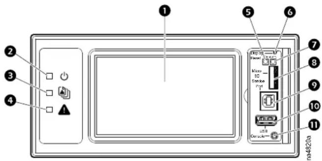
Item Description Function
| 1 | LCD Display | 4.3-inch touch-screen color display |
| 2 | Power LED The cooling unit is powered when the LED is illuminated. Unit firmware is updating when LED is blinking. | |
| 3 | Check Log LED | When this LED is illuminated, a new entry has been made to the event log. |
| 4 | Alarm LED | Displays current alarm condition of unit. |
| 5 | Status LED | Displays current network management card status. |
| 6 | Display Reset button | Resets the display microprocessor. This has no effect on the air conditioner controller. |
| 7 | Link-RX/TX (10/100) LED | Displays current network link status. |
| 8 | Micro SD card slot | Memory card expansion slot. |
| 9 | Service port USB-B port used only by service personnel. | |
| 10 | USB-A port Supports firmware upgrades. | |
| 11 | Serial Configuration port Connects the display to a local computer to configure initial network settings or access the command line interface (CLI). | |
Using a USB Drive to Transfer and Update Files
Update Display Interface Firmware
- Insert a USB drive into an available port on the PC and verify that the drive is formatted as a FAT32 file system.
- Create a folder named apcfirm on the USB drive.
- Acquire the firmware files from the local support team or the Schneider Electric Web site.
- Unzip and extract the files to the apcfirm folder.
- Operating system (*_aos_*.bin)
- Boot monitor (*.bootmon*.bin)
-
Application (*_RD3xx_*.bin)
-
Use a text editor, like Notepad, to create a file named upload.rcf.
-
List the filename for each firmware module in the order to be transferred. An example is shown below.
IMPORTANT: The files must be listed in the correct order in the upload.rcf file.
- The BM (bootmon) file must be listed first: BM=apc_hw06_bootmon_105.bin
- The AOS (operating system) file must be listed second: AOS=apc_hw06_aes_609.bin
- The APP (application) must be listed third: APP=apc_hw06_rd3xx4i_*.bin
NOTE: * in the APP file name is the revision number and will change with each release.
- Save the upload.rcf file in the apcfirm folder.
Your apcfirm folder should look similar to the example folder shown here:
| Name | Date modified | Type | Size |
| apc_hw06_aos_646.bin | 3/16/2017 3:55 PM | BIN File | 3,058 KB |
| apc_hw06_bootmon_108.bin | 3/16/2017 3:55 PM | BIN File | 256 KB |
| apc_hw06_unflrtsa_600g.bin | 4/20/2017 4:41 PM | BIN File | 2,454 KB |
| upload.rcf | 3/17/2017 7:16 AM | RCF File | 1 KB |
- Insert the USB drive into the USB-A port on the display interface.
A confirmation message appears on the display interface.
- Press the Display Reset button to reset the display interface.
The display interface resets and transfers files. The display will resume operation when transfer is complete.
NOTE: The touch screen will be disabled during the transfer process. There is no disruption of unit operation during the file transfer process.
-
Remove the USB drive when the file transfer is complete.
-
Check the firmware version on the touch screen display interface on the Main > About > Display screen.
-
To update the firmware on additional units, repeat from step 8.
Update Controller Firmware
Before starting the transfer, make sure the USB drive is formatted in FAT32.
Path: Main > Configuration > Service > USB > Firmware Download
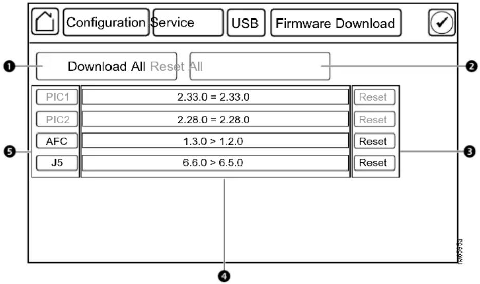
Item Description Function
| 1 | Download All | Downloads all available firmware updates. |
| 2 | Reset All | Resets all controllers that have had firmware updates.This button will appear gray if no controllers need to be reset. |
| 3 | Reset Resets the corresponding controllers individually. | |
| 4 | Firmware revision | These buttons will appear gray if the controller cannot be reset or is not present. |
- Download the firmware upgrade files and unzip them.
- Create a folder named fw on the USB flash drive.
- Place the extracted module files in the fw directory.
- Use a text editor to create a file named fw.rcf. (The file extension must be .rcf, not .txt for example.)
- In fw.rcf, add a line for each firmware module that needs to be updated. The following are examples of formatting for the file.
NOTE: Make sure the j5.cbp file remains in directory: the J5 controller may download the firmware on its own if there is no valid firmware or the personality jumpers do not match the current loaded firmware.
$$ \mathrm{PIC1} = \text { pic1 - 2.33.0.cbp } $$
$$ \mathrm{PIC2} = \text { pic2 - 2.28.0.cbp } $$
$$ \mathrm{AFC} = \mathrm{AFC-1.11.0.cbp} $$
$$ J 5 = J 5 - 1. 0. 3. c b p $$
- Place fw.rcf in the fw folder on the USB drive.
- Insert the USB drive into the USB port on the display interface.
- On the display interface, navigate to Main > Configuration > Service > USB > Firmware Download.
- Select the firmware to download for the controllers individually or for all devices.
- After downloading the firmware, reset the controllers individually or reset all.
- Check that the update was completed successfully using the procedures in Verify Updates, page 121.
Verify Updates
Verify Success of the Transfer
To verify whether a firmware upgrade succeeded, you can use the xferStatus command in the command line interface to view the last transfer result. Alternatively, you can use an SNMP GET to receive the mfiletransferStatusLastTransferResult OID.
NOTE: This is only valid for checking the success of the touch screen firmware update.
Last Transfer Result Codes
Possible transfer errors include the TFTP or FTP server not being found, or the server refusing access, the server not finding or not recognizing the transfer file, or a corrupt transfer file.
Verify Version Numbers of Installed Firmware
Use the display interface or the Web user interface to verify the versions of the upgraded firmware modules. You can also use an SNMP GET to the MIB II sysDescr OID. In the command line interface, use the About command.
Service Menu
▲WARNING
HAZARD TO EQUIPMENT OR PERSONNEL
All work must be performed by Schneider Electric qualified and trained personnel.
Failure to follow these instructions can result in death, serious injury, or equipment damage.
The Service menus contain settings related to the operation of the unit that should only be changed by qualified personnel.
Service Menu Access
The Service menus are only accessible to service personnel. If you need to access the Service menus, you will need to contact technical support with the code displayed in the message window. After receiving a service code from technical support, enter the code in the appropriate window on the display.
Unit Configuration
Path: Main > Configuration > Service > Unit
NOTE: All changes to settings must be performed by qualified personnel.
- Number of Evaporator Fan Power Supplies: Set the number of fan power supplies installed in the electrical box. (1 or 2)
- Evap Fan PS Calibration: An evaporator fan power supply needs to be calibrated if a new fan power supply has been added to the unit or if a fan power supply has been replaced. Select Start and press OK to start calibration.
- Evap Fan PS Calibration: In progress is displayed if the fan power supply is being calibrated; Finished is displayed when calibration is complete.
- Evap PS 1 Cal Factor: This calibration factor is a reading from the power supply when it is off: a base number for zero amps. A normal reading is 2048 ±10.
- Evap PS 2 Cal Factor: This calibration factor is a reading from the power supply when it is off: a base number for zero amps. A normal reading is 2048 ±10.
- Air Filter Type: Select whether the air filters are Standard or High Efficiency.
- Maximum Fan Speed: Set the maximum fan speed percentage allowed for the evaporator fans. (30.0–100.0% for one power supply, 30.0–130.0% for two power supplies)
- Minimum Fan Speed: Set the minimum fan speed percentage allowed for the evaporator fans. (20.0–100.0%)
- Air Filter Sensor Type: Select whether the air filters sensors type are Binary or Analog.
• Voltage: Select the voltage of the unit.
。 Not Configured
。 100-120v
200-240v -
Power Feed Type: Select whether the power feed is a Single or Dual power feed.
-
Condensate Drain Type: Select the type of condensate drain used by the unit. (Gravity or Pump)
• Humidity Sensor Present: Select Yes if the sensor is present. - Shutdown Input Present: Select Yes if the shutdown input is present.
- Shutdown Input State: Displays the normal state of the shutdown input. (Open or Closed)
- Air Filter Type: Select whether the air filters are Standard or High Efficiency.
- Number of Rack Inlet Temp Sensors in Unit: Set the number of rack inlet air temperature sensors connected to the unit. (0–4)
- Number of Leak Detectors in Unit: Set the number of leak sensors connected to the unit. (0–4)
- EEV Position: The current position in percentage of the EEV.
- EEV Opening at Startup: Enter the starting position of the EEV for the compressor.
- EEV Mini Pos: Limits the EEV opening position when the superheat control is active. (%)
- EXV Type: Select whether the electronic expansion valve is a Carel valve or a Sporlan valve.
• Humidifier Control: Enable (Yes) or disable (No) humidification.
NOTE: For ACRH301P units only. - Dehumidification Control: Enable (Yes) or disable (No) dehumidification.
NOTE: For ACRH301P units only. - Heat Assist And Reheat Control: Enable (Yes) or disable (No) heat assistance and reheat control..
NOTE: For ACRH301P units only. - Heater Max Output: The maximum output percentage for the heater. (0-100%)
NOTE: For ACRH301P units only. - Reheat Gain 'P': The reheat control proportional coefficient.
NOTE: For ACRH301P units only. - Superheat Recovery: Select Yes to enable the superheat recovery control. Select No to disable superheat recovery control. When disabled, this function will be available only once the compressor is started.
- Superheat Recovery Timeout: Enter the time period during which the superheat recovery function is available after the compressor is started. (5–60 minutes)
- EEV Sync Control: Enable (Yes) or disable (No) the EEV synchronization process after the time period entered for EEV Sync Control.
- EEV Sync Hours: EEV synchronization time period. (24–720 hours) data dictionary says 720
- RH By PwrLn2: Enable or disable features relating to the humidifier and heater on the secondary power supply.
- Pump Down: Enable or disable features relating to pump down
- Coil Type: Select the coil type as Not Configured, Energy Saving, Twin Cool or DX.
- Twin Cool Select: Select twin cool type as Not Configured, DX or CW, this setting will be valid only when Coil Type is selected as Twin Cool.
- Dry Cooler Control Type: Select dry cooler control type as Not Configured, Discrete or Modulated.
NOTE: If a new configuration is made among Coil Type, Twin Cool Select or Dry Cooler Control Type, the indoor unit power must be switched off and then switched on again to make the change valid.
- Dry Cooler Minimum Fan Speed: Set the dry cooler minimum fan speed.
- Energy Saver Coil Enable Threshold: The threshold at which energy saver coil will be enabled.
- Bypass Valve Startup Position: The startup position of bypass valve.
- EEV Quick Adjust Min Position: When superheat is too low, the EEV will be decreased quickly. This set EEV minimum adjust step when quick adjust is active.
- Energy Saver Stop DX Integration FS: When over this supply temperature integration value in period of time, if supply temperature is too low, compressor will be closed and put into energy saving mode.
- DX Only Run DX Integration FS: When over this supply temperature integration value in period of time, if supply temperature is too high in energy saving mode, the unit will start the compressor to assist cooling.
- DX Only Run DX Deadband: If supply temperature is too high in energy saving, the unit will start the compressor to assist cooling. This parameter is the dead band of mode switch.
- DX Only DC Fan Min Speed: The minimum speed of dry cooler fans at non-energy saving mode.
- Low Coolant Temp Clear Integration FS: When over this inlet water temperature integration value in period of time, if the inlet coolant temperature is high, Low Coolant Temperature warning will be cleared. Default 300F·S.
- Low Coolant Temp Generate Integration FS: When over this inlet water temperature integration value in period of time, if the inlet coolant temperature is too low, a warning Low Coolant Temperature will be generated. Default 3000F·S.
- Low Coolant Temp Clear Deadband: When the inlet coolant temperature is too high, the parameter is the dead band for clearing Low Coolant Temperature warning.
- ES Dehum Dewpoint Deadband: Energy saving mode dehumidification dewpoint dead band.
- ES Dehum Coolant Temp High FS: When over this inlet water temperature integration value in period of time, if the inlet coolant temperature is too high in dehumidification during energy saving mode, will start the compressor.
- LF SW Active Limit Max Fan Speed: Once the low float switch is activated, the max fan speed is limited by this parameter.
- LF SW Active Limit Max Fan Speed Hold Time: Once the low float switch is activated, this is the limit fan speed hold time.
- Coolant Liquid Type: Select Water, Propylene Glycol or Ethylene Glycol as the coolant liquid type.
- Coolant Liquid Freezing Point: Set the coolant liquid freezing point, based on coolant liquid type.
- BPHE Bypass Valve Min Position: Brazed plate heat exchanger valve minimum position. Default is set at 5%, should be set to 15% when Coil Type is set as DX and Dry Cooler Control Type is set as Discrete.
Containment Systems
Path: Main > Configuration > Service > Containment Systems
- Number of Active Flow Controllers: Set the number of Active Flow Controller units in the group. (0–5)
• Active Flow Control Lamp Test: When set to On, the Active Flow Controller (s) LEDs will cycle through a red, green, and blue illumination pattern. - Active Flow Control Bias: This setting is used to change the bias of the controller by adjusting the contained aisle pressure threshold. Zero is the default setting. Only qualified service personnel can make changes to these settings.
Hot Aisle Containment (HACS)
- If the cooling units seem to be under-cooling, select Negative or Slightly Negative to adjust the aisle pressure for additional cooling.
- If the cooling units seem to be over-cooling, select Positive or Slightly Positive to adjust the aisle pressure for less cooling.
- Cold Aisle Containment (CACS)
- If the cooling units seem to be under-cooling, select Positive or Slightly Positive to adjust the aisle pressure for additional cooling.
- If the cooling units seem to be over-cooling, select Negative or Slightly Negative to adjust the aisle pressure for less cooling.
| Setting Blue LED—HACS | Red LED—CACS | Setpoint Green LED | Red LED—HACSBlue LED—CACS |
| Positive | < -0.008 in. ±3% | 0.004 ±0.0004 in. | > 0.016 in. ±3% |
| Slightly Positive < -0.010 in. ±3% | 0.002 ±0.0004 in. | > 0.014 in. ±3% | |
| Zero | < -0.012 in. ±3% | 0.000 ±0.0004 in. | > 0.012 in. ±3% |
| Slightly Negative < -0.014 in. ±3% | -0.002 ±0.0004 in. | > 0.010 in. ±3% | |
| Negative | < -0.016 in. ±3% | -0.004 ±0.0004 in > 0.008 | in. ±3% |
Run Hours and Service Intervals
Path: Main > Configuration > Service > Run Hours
Each component interval setting has an alarm. If set to Enable, the annunciator will sound when the service interval for the component has elapsed. The alarms are reset by selecting the check box for the Reset XXX Service Alarm for each component and pressing OK. Enable service interval alarms and set the number of weeks to service each component in the XXX Alarm Interval fields. The run hours counter for the service intervals can be reset or adjusted by qualified personnel after a component has been serviced. The following components can have service intervals configured:
NOTE: Service alarms for the unit and for the air filters are enabled by default. Other alarms must be enabled after startup.
NOTE: Visible alarms will vary depending upon the unit configuration.
- Unit
- Air Filter
- Compressor
- Dry Cooler
- Condensate Pump
- Fan 1
- Fan 2
- Fan 3
- Fan 4
- Fan 5
- Fan 6
- Fan 7
- Fan 8
- Humidifier
- Heater 1
- Heater 2
- Condenser Fan
Compressor Settings
Path: Main > Configuration > Service > Compressor Drive
- Compressor Speed: Displays the current speed of the compressor. (Hz)
- Maximum Compressor Speed: Enter the maximum speed allowed for the compressor. (60.0–100.0 Hz)
- Minimum Compressor Speed: Enter the minimum speed allowed for the compressor. (15.0–60.0 Hz)
NOTE:
- 20 Hz is suggested when unit is equipped with a flooded receiver kit.
- 20 Hz is suggested when a flooded receiver kit is not used and the ambient temperature is higher than 0^ C ( 32^ F).
- 40 Hz is suggested for all other scenarios.
- Startup Compressor Speed: Enter the target speed of the compressor (Hz) when it is first turned on. The target speed is valid until the evaporating temperature exceeds 0°C (32°F). After that, the compressor is controlled by the supply temperature PID. (15–100 Hz)
- Maximum Compressor Restarts: Enter how many compressor restarts are allowed within 30 minutes after a compressor trips. The variable frequency
drive (VFD) will shut down the compressor if the number of restarts exceeds this value within 30 minutes. (1–20)
- Enable Envelope Management: Select whether or not envelope management is enabled.
- Compressor Envelope Start Offset: The environmental action offset. This is the temperature offset at which the controller will start applying the compressor envelope management process. (2.8–5.6°C (6.2–12.3°F))
- Envelope Maximum Condensing Temperature: The environmental maximum action setpoint. TBD
- Heat Sink Temperature: Displays the compressor heat sink temperature. (°C (°F))
- Current: Displays the compressor current draw. (A)
- Compressor Power: The compressor power consumption. (kW)
- Alarm Status: The compressor alarm word used for diagnostics.
- Warning Status: The compressor warning word used for diagnostics.
- Software Version: The software version of the compressor controller.
- Serial Number: The serial number of the compressor
- Software ID: The compressor driver software ID.
Oil Return Management
Path: Main > Configuration > Service > Oil Return Management
NOTE: All changes to settings must be performed by qualified personnel.
- Oil Return Management: Select Yes to enable oil return management. This increases the speed for short periods (Boost Duration) when the speed is too low (Low Speed Limit) to ensure sufficient quantities of oil in the compressor crankcase.
- Boost Duration: The length of time for which the compressor speed will be increased to the Boost Speed. (60–300 s)
- Boost Speed: The speed to which the compressor will be boosted during the Boost Duration. (80–200 Hz)
- Low Speed Running Time: When oil return management is enabled and the compressor speed is less than the Low Speed Limit for this entered length of time, the VFD boosts the compressor speed to the Boost Speed for the length of time entered in Boost Duration. (1–1400 minutes)
- Low Speed Limit: The compressor speed at which Oil Return Management will be activated. (80–200 Hz)
PID Settings
NOTICE
DAMAGE TO EQUIPMENT
This procedure is to be performed by Schneider Electric qualified personnel only. Improperly set PID controls could result in equipment damage.
Failure to follow these instructions can result in equipment damage.
Path: Main > Configuration > Service > PIDs
The Proportional plus Integral plus Derivative (PID) loops control the output of the fans and other components.
- Superheat Control: Displays whether the PID algorithm for superheat is running (Run) or not (Stop).
- Superheat Setpoint: Set the target value for the temperature difference for refrigerant entering and leaving the coil. (4.4–22.2Δ°C (8.0–40.0Δ°F))
- Superheat Gain (P): When the compressor is started, the superheat controller will use this proportional gain for the period of time entered for Time during the startup phase. Once the unit is stable, the standard PID gains will resume.
- Time: When the compressor is started, during this time of period, the superheat controller will use a special proportional gain. (0-120 minutes)
- Superheat PID Gain: The proportional multiplier (gain) for the temperature sensors installed on the inlet and outlet of the cooling coil. The proportional multiplier adjusts for the difference (error) between the measured value and the setpoint.
- Superheat PID Integral: The integral multiplier (reset rate) for the temperature sensors installed on the inlet and outlet of the cooling coil. The integral multiplier adjusts for error measurement and the amount of time that the error has existed. The integral multiplier adds to or subtracts from the output in small increments to correct for the offset error caused by the proportional contribution.
- Superheat PID Derivative: The derivative multiplier (derivative) for the temperature sensors installed on the inlet and outlet of the cooling coil. The derivative multiplier adjusts the output for rapid changes in the error, correcting for the rate of change of the error over time.
- Superheat PID Reset: Select Yes to reset the superheat setpoint PID values to factory default settings.
- Airflow Control: Displays whether the PID algorithm for airflow control is running (Run) or not (Stop).
- Active Flow Control Bias: This setting is used to change the bias of the controller by adjusting the contained aisle pressure threshold. Zero is the default setting. Only qualified service personnel can make changes to these settings.
• Hot Aisle Containment (HACS) - If the cooling units seem to be under-cooling, select Negative or Slightly Negative to adjust the aisle pressure for additional cooling.
- If the cooling units seem to be over-cooling, select Positive or Slightly Positive to adjust the aisle pressure for less cooling.
- Cold Aisle Containment (CACS)
- If the cooling units seem to be under-cooling, select Positive or Slightly Positive to adjust the aisle pressure for additional cooling.
- If the cooling units seem to be over-cooling, select Negative or Slightly Negative to adjust the aisle pressure for less cooling.
| Setting Blue LED—HACS | Red LED—CACS | Setpoint Green LED | Red LED—HACSBlue LED—CACS |
| Positive | < -0.008 in. ±3% | 0.004 ±0.0004 in. | > 0.016 in. ±3% |
| Slightly Positive < -0.010 in. ±3% | 0.002 ±0.0004 in. > 0.014 in. ±3% | ||
| Zero | < -0.012 in. ±3% | 0.000 ±0.0004 in. | > 0.012 in. ±3% |
| Slightly Negative < -0.014 in. ±3% | -0.002 ±0.0004 in. > 0.010 in. ±3% | ||
| Negative | < -0.016 in. ±3% | -0.004 ±0.0004 in | > 0.008 in. ±3% |
- AirFlow PID Gain: The proportional multiplier (gain) for the evaporator fan when an AFC is present. The proportional multiplier adjusts for the difference (error) between the measured value and the setpoint.
- AirFlow PID Integral: The integral multiplier (reset rate) for the evaporator fan when an AFC is present. The integral multiplier adjusts for error measurement and the amount of time that the error has existed. The integral multiplier adds to or subtracts from the output in small increments to correct for the offset error caused by the proportional contribution.
- AirFlow PID Derivative: The derivative multiplier (derivative) for the evaporator fan when an AFC is present. The derivative multiplier adjusts the output for rapid changes in the error, correcting for the rate of change of the error over time.
- AirFlow PID Reset: Select Yes to reset the airflow control PID values to factory default settings.
- Condenser Control: Displays whether the PID algorithm for the condenser fan is running (Run) or not (Stop).
- Condenser Temperature Setpoint: Enter the setpoint that will be used by the condenser temperature controller when the condensing temperature sensor does not provide a value (10.0–93.3°C (50.0–200.0°F)). Default is set at 35°C (95°F), should be set to 45°C (113°F) when Coil Type is set as DX and Dry Cooler Control Type is set as Discrete
- Condenser & PHE Valve PID Gain: The proportional multiplier (gain) for the condenser fan and the plate heat exchanger. The proportional multiplier adjusts for the difference (error) between the measured value and the setpoint.
- Condenser & PHE Valve PID Integral: The integral multiplier (reset rate) for the condenser fan and the plate heat exchanger. The integral multiplier adjusts for error measurement and the amount of time that the error has existed. The integral multiplier adds to or subtracts from the output in small increments to correct for the offset error caused by the proportional contribution.
- Condenser & PHE Valve PID Derivative: The derivative multiplier (derivative) for the condenser fan and the plate heat exchanger. The derivative multiplier adjusts the output for rapid changes in the error, correcting for the rate of change of the error over time.
- Condenser & PHE Valve PID Reset: Select Yes to reset the condenser fan and plate heat exchanger control PID values to factory default settings.
- Supply Air Control: Displays whether the PID algorithm for the supply air is running (Run) or not (Stop).
- Supply Air Setpoint: The required temperature of the air expelled into the surrounding environment. (15.0–30.2°C (59.0–86.4°F))
- Delta-T Setpoint: When the group is programmed for HACS or RACS mode, this value specifies the desired temperature difference between the supply and return air temperatures when an AFC is not present. (10F/5.6C, 15F/8.3C, 20F/11.1C, 25F/13.9C, 30F/16.7C, 35F/19.4C, 40F/22.2C)
NOTE: Set a lower Cool Setpoint or a smaller Delta-T Setpoint to assist with start-up during winter.
- Supply Air PID Gain: The proportional multiplier (gain) for the supply air sensors installed on the unit. The proportional multiplier adjusts for the difference (error) between the measured value and the setpoint.
- Supply Air PID Integral: The integral multiplier (reset rate) for the supply air temperature sensors installed on the unit. The integral multiplier adjusts for error measurement and the amount of time that the error has existed. The integral multiplier adds to or subtracts from the output in small increments to correct for the offset error caused by the proportional contribution.
- Supply Air PID Derivative: The derivative multiplier (derivative) for the supply air temperature sensors installed on the unit. The derivative multiplier adjusts the output for rapid changes in the error, correcting for the rate of change of the error over time.
- Supply Air PID Reset: Select Yes to reset the supply air temperature PID values to factory default settings.
- Rack Inlet Control: Displays whether or not the PID algorithm for the rack inlet air temperature is running (Run) or not (Stop).
- Cool Setpoint: Set the temperature that the cooling group should maintain in the IT space. (17.8–35.0°C (64.0–95.0°F))
- Rack Inlet PID Gain: The proportional multiplier (gain) for the rack inlet air temperature sensors connected to the unit. The proportional multiplier adjusts for the difference (error) between the measured value and the setpoint.
- Rack Inlet PID Integral: The integral multiplier (reset rate) for the rack inlet air temperature sensors connected to the unit. The integral multiplier adjusts for error measurement and the amount of time that the error has existed. The integral multiplier adds to or subtracts from the output in small increments to correct for the offset error caused by the proportional contribution.
- Rack Inlet PID Derivative: The derivative multiplier (derivative) for the rack inlet air temperature sensors connected to the unit. The derivative multiplier adjusts the output for rapid changes in the error, correcting for the rate of change of the error over time.
- Rack Inlet PID Reset: Select Yes to reset the rack inlet air temperature PID values to factory default settings.
- DC Fans DX PID Gain: The proportional multiplier (gain) for DC Fans in DX mode. The proportional multiplier adjusts for the difference (error) between the measured value and the setpoint.
- DC Fans DX PID Integral: The integral multiplier (reset rate) for DC Fans in DX mode. The integral multiplier adjusts for error measurement and the amount of time that the error has existed. The integral multiplier adds to or subtracts from the output in small increments to correct for the offset error caused by the proportional contribution.
- DC Fans DX PID Derivative: The derivative multiplier (derivative) for DC Fans in DX mode. The derivative multiplier adjusts the output for rapid changes in the error, correcting for the rate of change of the error over time.
- DC Fans DX PID Reset: Select Yes to reset the DC Fans in DX mode PID values to factory default settings.
- ES Valve PID Gain: The proportional multiplier (gain) for energy save valve. The proportional multiplier adjusts for the difference (error) between the measured value and the setpoint.
- ES Valve PID Integral: The integral multiplier (reset rate) for energy save valve. The integral multiplier adjusts for error measurement and the amount of time that the error has existed. The integral multiplier adds to or subtracts from the output in small increments to correct for the offset error caused by the proportional contribution.
- ES Valve PID Derivative: The derivative multiplier (derivative) for the energy save valve. The derivative multiplier adjusts the output for rapid changes in the error, correcting for the rate of change of the error over time.
-
ES Valve PID Reset: Select Yes to reset the energy save valve PID values to factory default settings.
-
DC Fans ES PID Gain: The proportional multiplier (gain) for energy save valve. The proportional multiplier adjusts for the difference (error) between the measured value and the setpoint.
- DC Fans ES PID Integral: The integral multiplier (reset rate) for DC Fans in energy saving mode. The integral multiplier adjusts for error measurement and the amount of time that the error has existed. The integral multiplier adds to or subtracts from the output in small increments to correct for the offset error caused by the proportional contribution.
- DC Fans ES PID Derivative: The derivative multiplier (derivative) for the DC Fans in energy saving mode. The derivative multiplier adjusts the output for rapid changes in the error, correcting for the rate of change of the error over time.
- DC Fans ES PID Reset: Select Yes to reset the DC Fans in energy saving mode PID values to factory default settings.
Tune the PID Loop
Tune the PID loop to optimize the performance of the cooling group.
NOTE: This procedure is to be performed by Schneider Electric qualified personnel only. The PID loop must be tuned after the equipment in the room is installed and running. The loop should be tuned periodically to account for changes in the room load.
- Adjust the integral and derivative constants to zero and the proportional constant to 1.0.
- Set the temperature setpoint value and start the cooling group.
- When the temperature reaches a stable value, increase the proportional constant by 0.5. If the temperature does not respond to this change, adjust the setpoint.
- Repeat step 3 until the temperature value starts to oscillate and the peak amplitude of the oscillations is constant.
- Note the time, in minutes, between the peaks of the oscillations. This is the Ultimate Period, P.
- Note the value of the proportional constant. This is the Ultimate Gain, G
- Compute the PID constants using the table below. Use the equations for that control method in the row to compute the values for each constant.
- Set each constant according to these calculations.
Control Method Proportional Integral Derivative
| P | 0.5 * GU | — | — |
| P+I | 0.45 * GU | 0.54 * G/PU | — |
| P+I+D | 0.6 * G | 1.2*GU/PU | 0.075 * G*PU |
You may need to further tune the PID loop in the following ways to account for changes in the room load.
| Loop Behavior | PID Tuning Correction |
| Slow response to temperature changes | Increase the proportional multiplier or increase the derivative multiplier. |
| Overcooling/undercooling after changes in the room load or changes in setpoint | Increase the derivative or the proportional multiplier. |
| Environmental temperature never reaches the setpoint | Increase the integral multiplier. |
| Overcooling/undercooling on constant room load | Decrease the integral multiplier. |
Maintenance
Maintenance Mode
NOTICE
UNIT MALFUNCTIONS
- Changing the settings incorrectly can cause malfunctions to your cooling unit.
- Only qualified service personnel should make changes to these settings.
Failure to follow these instructions can result in equipment damage.
Path: Main > Configuration > Service > Maintenance Mode
Maintenance mode is used to perform maintenance checks. Qualified personnel can manually control components within the unit to check for errors and mechanical issues. The unit must be in an Off state before being put in maintenance mode. Press OK next to each setting to accept changes. Some data items are duplicated on multiple screens to provide the status of components while adjusting settings.
- Maintenance Mode: Select which type of maintenance mode to enter.
- Enable_Indefinitely: The unit will remain in maintenance mode until it is disabled.
- Enable_With_Timeout: The unit will remain in maintenance mode for two minutes.
- Disable: The unit will exit maintenance mode and resume normal operation.
- Maximum Cooling: Select Max to set all of the maintenance mode actuator settings to the maximum output: condenser fan, evaporator fan, EEV position, and compressor speed.
- EEV Position: The current open percentage of the electronic expansion valve. (%)
- Suction Pressure: The pressure of the refrigerant at the suction line. (bar (psi))
- Discharge Pressure: The pressure of the refrigerant at the discharge line. (bar (psi))
- Compressor Speed: Enter a speed to which the compressor will be manually commanded. (0.0–100.0 Hz)
- Avg. Fan Speed: The current average speed of the eight fans in the indoor unit. (rpm)
- Fan Speed: The current speed of the evaporative fans. (%)
- Fan Speed: Enter a fan speed percentage to manually control the evaporator fans. (0.0–100.0 %)
- Condenser Fan Speed: The current speed of the condenser fan. (rpm)
- Condenser Fan Speed: The current speed of the condenser fan. (%)
- Condenser Fan Speed: Enter a fan speed percentage to manually control the fan of the condensing unit. (0.0–100.0 %)
- EEV Position: The current open percentage of the electronic expansion valve. (%)
- EEV Position: Enter an open percentage for the electronic expansion valve. When the compressor speed is greater than 0 Hz, the EEV is controlled by the superheat PID controller. (0.0–100.0%)
- Liquid Line Solenoid: The current state of the liquid line solenoid valve: Open or Closed.
- Liquid Line Solenoid: Select to open or close the liquid line solenoid valve. When the compressor speed is greater than 0 Hz, the liquid line is forced open. (Open or Closed)
• Electric Heater 1: Select Open or Closed to control the heater relay.
NOTE: For ACRH301P units only.
• Electric Heater 2: Select Open or Closed to control the heater relay.
NOTE: For ACRH301P units only.
- CPY Humidifier Request: The condensate production request to the humidifier controller. Available on units equipped with a humidifier only. (%)
NOTE: For ACRH301P units only.
- Manual Drain: Select Yes to manually drain the humidifier canister; select No to not manually drain the humidifier canister.
NOTE: For ACRH301P units only.
- Humidifier Actual Production: The actual amount of condensate produced by the humidifier. (%)
NOTE: For ACRH301P units only.
- Humidifier Current: The humidifier electrical current in amps. Available on units equipped with a humidifier only.
NOTE: For ACRH301P units only.
- Humidifier Water Conductivity: The conductivity level of the water in the humidifier. Available on units equipped with a humidifier only. (μS/cm)
NOTE: For ACRH301P units only.
- Alarm Relay 1: Select open or closed to control the alarm relays. (Open or Closed)
- Alarm Relay 2: Select open or closed to control the alarm relays. (Open or Closed)
- Alarm Relay 3: Select open or closed to control the alarm relays. (Open or Closed)
- Alarm Relay 4: Select open or closed to control the alarm relays. (Open or Closed)
- Outlet Evap Coil Temperature: The temperature of the refrigerant leaving the evaporative coil. (°C (°F))
- Inlet Evap Coil Temperature: The temperature of the refrigerant entering the evaporative coil. (°C (°F))
- Upper Supply Temperature: The temperature from the top supply air temperature sensor connected to this unit. (°C (°F))
- Lower Supply Temperature: The temperature from the bottom supply air temperature sensor connected to this unit. (°C (°F))
- Upper Return Temperature: The temperature from the top return air temperature sensor connected to this unit. (°C (°F))
- Lower Return Temperature: The temperature from the bottom return air temperature sensor connected to this unit. (°C (°F))
- Suction Pressure: The pressure of the refrigerant at the suction line. (bar (psi))
- Discharge Pressure: The pressure of the refrigerant at the discharge line. (bar (psi))
- EEV Position: The current open percentage of the electronic expansion valve. (%)
- Liquid Line Solenoid: The current state of the liquid line solenoid valve: Open or Closed.
- Fan Speed: The current speed of the evaporative fans. (%)
- Condenser Fan Speed: The current speed of the condenser fan. (%)
- Choke Valve Position: The position of the choke valve.
- Bypass Valve Position: The position of the bypass valve.
- MM Dry Cooler Fan Speed: The speed of dry cooler fan in the maintenance mode.
Monthly Preventive Maintenance
Photocopy the following pages and use them during the maintenance procedures. After they have been completed, save them for future reference.
Prepared By: ____
Model Number: ____
Serial Number: ____
Date: ____
Perform the following monthly maintenance check lists.
Environment
Supply air temperature sensor reading: ____
☐ Return air temperature sensor reading: ____
Record the alarm history for the last month.
Cleanliness
☐ Check the condition of the air filters. Clean or change if necessary.
Mechanical
⚠️ DANGER
HAZARD OF ELECTRIC SHOCK, EXPLOSION, OR ARC FLASH
- Apply appropriate personal protective equipment (PPE) and follow safe electrical work practices.
- This equipment must be installed and serviced by qualified and trained personnel only.
- Turn off all power supplying this equipment before working on or inside equipment.
- Replace all devices, doors, and covers before turning on power to this equipment.
Failure to follow these instructions will result in death or serious injury.
▲WARNING
HAZARD TO EQUIPMENT OR PERSONNEL
All work must be performed by Schneider Electric qualified and trained personnel.
Failure to follow these instructions can result in death, serious injury, or equipment damage.
☐ Check the evaporator fans for abnormal noise or vibration.
☐ Check the liquid line sight glass moisture indicator.
☐ Check the liquid line sight glass for bubbles.
☐ Check the oil level in the compressor sight glass.
Electrical
⚠️ DANGER
HAZARD OF ELECTRIC SHOCK, EXPLOSION, OR ARC FLASH
- Apply appropriate personal protective equipment (PPE) and follow safe electrical work practices.
- This equipment must be installed and serviced by qualified and trained personnel only.
- Turn off all power supplying this equipment before working on or inside equipment.
- Replace all devices, doors, and covers before turning on power to this equipment.
Failure to follow these instructions will result in death or serious injury.
▲WARNING
HAZARD TO EQUIPMENT OR PERSONNEL
All work must be performed by Schneider Electric qualified and trained personnel.
Failure to follow these instructions can result in death, serious injury, or equipment damage.
☐ Inspect the electrical panel doors and covers for damage or loose hardware.
☐ Check the condenser electrical panel and covers for damage or loose hardware.
Functional Tests
☐ Check the operation of the display interface.
Quarterly Preventive Maintenance
Photocopy the following pages and use them during the maintenance procedures. After they have been completed, save them for future reference.
Prepared By: ____
Model Number: ____
Serial Number: ____
Date: ____
Perform the following quarterly maintenance check lists in addition to the monthly check lists.
Environment
Record the Supply Air Setpoint: ____
Record the Cool Setpoint: ____
Cleanliness
☐ Check for debris in the condensate pan. Clean as needed.
Mechanical
⚠️ DANGER
HAZARD OF ELECTRIC SHOCK, EXPLOSION, OR ARC FLASH
- Apply appropriate personal protective equipment (PPE) and follow safe electrical work practices.
- This equipment must be installed and serviced by qualified and trained personnel only.
- Turn off all power supplying this equipment before working on or inside equipment.
- Replace all devices, doors, and covers before turning on power to this equipment.
Failure to follow these instructions will result in death or serious injury.
▲WARNING
HAZARD TO EQUIPMENT OR PERSONNEL
All work must be performed by Schneider Electric qualified and trained personnel.
Failure to follow these instructions can result in death, serious injury, or equipment damage.
Record the suction and discharge pressures: ____
Record the evaporator superheat temperature: ____
Electrical
⚠️ DANGER
HAZARD OF ELECTRIC SHOCK, EXPLOSION, OR ARC FLASH
- Apply appropriate personal protective equipment (PPE) and follow safe electrical work practices.
- This equipment must be installed and serviced by qualified and trained personnel only.
- Turn off all power supplying this equipment before working on or inside equipment.
- Replace all devices, doors, and covers before turning on power to this equipment.
Failure to follow these instructions will result in death or serious injury.
▲WARNING
HAZARD TO EQUIPMENT OR PERSONNEL
All work must be performed by Schneider Electric qualified and trained personnel.
Failure to follow these instructions can result in death, serious injury, or equipment damage.
☐ Check wiring harnesses and molded connectors.
☐ Check customer interface wiring connections.
☐ Check temperature and humidity sensor connections.
Semi-Annual Preventive Maintenance
Photocopy the following pages and use them during the maintenance procedures. After they have been completed, save them for future reference.
Prepared By: ____
Model Number: ____
Serial Number: ____
Date: ____
Perform the following quarterly maintenance check lists in addition to the monthly and quarterly check lists.
Environment
☐ Check for visible damage to the cooling unit.
☐ Check for dirt, dust, debris, and liquid stains in and around the cooling unit.
Cleanliness
☐ Check for debris in the condensate pan. Clean as needed.
☐ Check and clean the evaporator coil.
Replace air filters. Reset air filter run hours alarm counter
Replace humidifier cylinder. Reset humidifier run hours alarm counter
Mechanical
⚠️ DANGER
HAZARD OF ELECTRIC SHOCK, EXPLOSION, OR ARC FLASH
- Apply appropriate personal protective equipment (PPE) and follow safe electrical work practices.
- This equipment must be installed and serviced by qualified and trained personnel only.
- Turn off all power supplying this equipment before working on or inside equipment.
- Replace all devices, doors, and covers before turning on power to this equipment.
Failure to follow these instructions will result in death or serious injury.
▲WARNING
HAZARD TO EQUIPMENT OR PERSONNEL
All work must be performed by Schneider Electric qualified and trained personnel.
Failure to follow these instructions can result in death, serious injury, or equipment damage.
☐ Check for refrigerant leaks on valves, threaded connections, and heat exchangers.
☐ Check refrigerant piping clamps and insulation. Secure as needed.
☐ Check that the condensate line is not obstructed or clogged.
Electrical
⚠️ DANGER
HAZARD OF ELECTRIC SHOCK, EXPLOSION, OR ARC FLASH
- Apply appropriate personal protective equipment (PPE) and follow safe electrical work practices.
- This equipment must be installed and serviced by qualified and trained personnel only.
- Turn off all power supplying this equipment before working on or inside equipment.
- Replace all devices, doors, and covers before turning on power to this equipment.
Failure to follow these instructions will result in death or serious injury.
▲WARNING
HAZARD TO EQUIPMENT OR PERSONNEL
All work must be performed by Schneider Electric qualified and trained personnel.
Failure to follow these instructions can result in death, serious injury, or equipment damage.
☐ Check circuit breaker and fuse block electrical connections.
☐ Check low voltage transformers, measure and record output voltage.
☐ Measure and record mains input voltage: ____
☐ Check and tighten electrical connections on the compressor inverter drive.
☐ Check and record the current draw for the following components:
- Fans:
- Compressor:
☐ Check condenser electrical components, fuses, contactors, speed controller.
Functional Tests
☐ Check the operation of the water leak detection device.
☐ Verify the cooling operation mode is functioning properly.
☐ Check condensate pump operation.
Troubleshooting
If necessary, call Technical Support describing the nature of the fault and its possible cause displayed on the control panel.
| Problem Possible | Cause Corrective Action | |
| Controls erratic or inoperative | Inlet temperature to cooling unit is higher than rated maximum temperature | Reduce the load or add additional cooling equipment. |
| Fans fail to start Cooling unit | Cooling unit shutdown due to an external command | Temporarily remove the input contact cable, if it is connected. |
| Single fan fails to start Verify | that the fan circuit breaker is ON. | |
| Cooling unit cannot obtain setpoint | Improper placement of remote temperature sensor | Verify that the remote temperature sensor is properly located in the cold aisle. |
| Dirty filter Clean the filter. | ||
| Dirty coil | Clean the coil. | |
| Application error | Contact Schneider Electric technical support | |
| Heat load is too far away | Place the cooling unit closer to the heat load. | |
| Water carryover | Improper fan speed selected | RACS and HACS modes only: Select the next-highest fan speed setting. |
| Room humidity is too high | Improve room sealing. | |
| Temperature control not tight enough | Improper placement of remote temperature sensor | Verify that the remote temperature sensor is properly located in the cold aisle. |
| Water on outside of cooling unit | Condensate drain hose is not connected or not properly routed outside the cooling unit | Verify that the condensate drain hose is properly connected to the pump and properly routed outside of the cooling unit.Verify that the condensate drain line does not exceed 3.5 m (11.5 ft) lift and 18.0 m (60.0 ft) horizontal run. |
| Leak in drain system Locate and repair the leak. | ||
| Cooling unit not leveled properly | Adjust the leveling feet of the cooling unit. | |
| Damaged piping insulation | Identify damaged area and repair the insulation. | |
| Display interface not operational, but cooling unit operates | Display interface not connected properly | Verify that the display interface cable is connected properly. |
| Incorrect air pressure | False filter clogs Verify that the ends of the clear plastic air tubes are not obstructed.Verify that the clear plastic air tubes are connected to the controller.Verify that the clear plastic air tubes are not pinched. | |
| Alarms do not show up on monitoring equipment (Customer Output Contact) | External monitoring equipment is not receiving power or is no functioning properly | Confirm that power, if required, is being supplied to the external equipment.If the cooling unit (+12 V or +24 V) is providing power to the external equipment, verify that the external equipment is ≤50 mA.Test the external equipment by bypassing the customer output contact.Verify Customer Output Contact settings. |
| Cooling unit does not shut down on command | Drive voltage | Verify that there is a drive voltage entering the input of the cooling unit. You may use the available +12 V or +24 V. You must also use the ground.Verify Customer Input Contact settings. |
| No communication with building management system (BMS) port | Improper connection | Confirm that the cooling unit is connected to the BMS port and not to the Control port.Make sure that the wire polarity is correct. Using a DC voltmeter, test the signal with no transmissions in progress. Expect the voltage at pin 2 to be greater than at pin 1 by at least 200 mV. Measure the cooling unit with the cable disconnected, and then measure it again with the cable connected. If the signal is less than 200 mV, the cooling unit may be reverse-wired.Make sure that every cooling unit has either two sets of wires in its connector or one set of wires and a terminating resistor of 100 to 120 ohms. |
| Cooling units are not communicating with each other | A-Link failure Verify that the first and last cooling units have one cable and a terminator.Verify that every other cooling unit has two cables.Confirm that the A-Link cables are connected to the ALink ports and that a network cable is connected to the network port.Verify that the number of cooling units in the cooling group matches the group number setting. | |
| Output air is 17°C (62°F) and fans are running at a very high rate of speed. | Upper or lower supply air sensor | Either upper or lower supply air temperature sensor has a fault. Verify that both supply air temperature sensors are installed and working properly. |
Worldwide Customer Support
Customer support for this or any other product is available at no charge in any of the following ways:
- Visit the Schneider Electric Web site to access documents in the Schneider Electric Knowledge Base and to submit customer support requests.
- www.schneider-electric.com (Corporate Headquarters)
Connect to localized Schneider Electric Web sites for specific countries, each of which provides customer support information.
- www.schneider-electric.com/support/
Global support searching Schneider Electric Knowledge Base and using esupport.
- Contact the Schneider Electric Customer Support Center by telephone or e-mail.
Local, country-specific centers: go to www.schneider-electric.com/support/contactwww.schneider-electric.com > Support > Operations around the world for contact information.
For information on how to obtain local customer support, contact the representative or other distributors from whom you purchased your product.
Schneider Electric
As standards, specifications, and design change from time to time, please ask for confirmation of the information given in this publication.

- InRow® Direct Expansion Air Conditioners
- ACRH301 and ACHU300 Series
- Operation and Maintenance
- Legal Information
- Table of Contents
- Alarms....61
- Network Management Card 68
- Access a Configured Unit 114
- Updating the Firmware.... 118
- Service Menu....122
- Maintenance....132
- Troubleshooting 143
- Safety
- Important Safety Instructions — SAVE THESE INSTRUCTIONS
- ⚠️ DANGER
- ▲WARNING
- ▲CAUTION
- NOTICE
- Please Note
- Safety During Operation
- HAZARD OF ELECTRIC SHOCK, EXPLOSION, OR ARC FLASH
- HAZARD FROM MOVING PARTS
- MOVING PARTS HAZARD
- HAZARD TO EQUIPMENT OR PERSONNEL
- HAZARD OF EQUIPMENT FALLING OVER
- HAZARD OF HIGH PRESSURE REFRIGERANT OR EQUIPMENT DAMAGE
- General Information
- Overview
- Original Instructions
- Save These Instructions
- Cross-Reference Symbol Used in This Manual
- Manual Updates
- Abbreviations
- Radio Frequency Interference
- California Proposition 65—Warning Statement for California Residents
- Commissioning
- Inspection Checklists
- Initial Inspection Checklist
- Ensure that
- Electrical Inspection Checklist
- ⚠️! DANGER
- ⚠️ ⚠️ WARNING
- ELECTRICAL HAZARD
- Mechanical Inspection Checklist
- Display Interface Inspection Checklist
- Start-Up Inspection Checklist
- While the equipment is operating, ensure that
- Final Inspection Checklist
- Charging the Equipment
- Calculating R410A Refrigerant Charge
- Refrigerant Charging Process
- Oil Charging Procedure
- DAMAGE TO EQUIPMENT
- InRow Advantages
- Operation
- Display Interface
- Alarm LED
- Status LED
- Link-RX/TX (10/100) LED
- Using the Display
- Overview Screen
- Home Screen/Main Menu
- Symbol Description
- Menu Description
- Display Controls
- Using the Path Statement
- Changing Settings
- First Log In
- Logging In/Password Entry
- Tests
- Calibrating the Display
- Testing Display LEDs and Annunciator
- Testing the AFC LED
- General Configuration
- Import and Export Unit Configuration
- Export
- Import
- Cooling Unit Configuration
- Configure the Unit
- Operation Settings
- Component Configuration
- Cooling Group Configuration
- Configure the Cooling Group
- Configure Modbus
- A-Link Connections
- CAT 5 PINOUT
- Active Flow Controllers (AFC)
- Control the Environment
- How the Modes of Operation Work
- Setpoints
- Active Flow Controller (AFC) Settings
- Path: Main > Configuration > Containment Systems
- Run Hours and Service Intervals
- Run Hours
- Run Hours Settings
- Service Intervals
- User Security Settings
- Add a New User or Edit an Existing User
- Delete a User
- Display Settings
- Language, Date, Time, and Temperature
- Screen Visibility and Audible Tones
- Restore Defaults
- Path: Main > Configuration > Restore Defaults
- Network Configuration
- Configure the Network
- TCP/IPv4 Settings
- TCP/IPv6 Settings
- Web Access Settings
- FTP Server Settings
- View Status Readings
- Item Description
- Cooling Unit Status
- Path: Main > Status > Unit
- Cooling Group Status
- Sensor Readings
- Refrigerant System
- Power Information
- Input/Output States
- About the Network
- About the Unit
- About the AFC
- About the Display
- Logs
- Event Log
- View Event Log
- Filter Event Log
- Clear Event Log
- Path: Main > Logs > Event Log
- Data Log
- Data Log Configuration
- Export Data
- Path: Main > Logs > Export Data
- Alarms
- Respond to Alarms
- View Active Alarms
- Clear Active Alarms
- Alarm Thresholds
- Network Management Card
- Quick Configuration
- TCP/IP Configuration Methods
- Device IP Configuration Wizard
- .ini File Utility
- BootP and DHCP Configuration
- Command Line Interface (CLI)
- Remote Access to the Command Line Interface (CLI)
- Local Access to the Command Line Interface (CLI)
- How to Use the CLI
- Command Help Syntax
- Example of a command that supports multiple options:
- Command Response Codes
- Argument Quoting
- Escape Sequences
- Example:
- Prompts for User Input during Command Execution
- Delimiter
- Option and Argument Inputs
- Network Management Card Command Descriptions
- ? or help
- Example 1:
- Example 2:
- about
- alarmcount
- boot
- bye, exit, or quit
- cd
- cipher
- clrrst
- console
- date
- delete
- dir
- dns
- eventlog
- exit
- firewall
- Parameters:
- format
- ftp
- help
- lang
- lastrst
- ledblink
- logzip
- netstat
- ntp
- ping
- portSpeed
- prompt
- pwd
- quit
- radius
- reboot
- resetToDef
- session
- smtp
- snmp
- snmpv3
- snmptrap
- system
- tcpip
- tcpip6
- user
- userdflt
- Access: Super User, Administrator
- web
- whoami
- xferINI
- Parameters: None.
- xferStatus
- Access a Configured Unit
- Web Interface
- Telnet and SSH
- Telnet for Basic Access
- SSH for High-Security Access
- Simple Network Management Protocol (SNMP)
- SNMPv1 Only
- SNMPv3 Only
- SNMPv1 and SNMPv3
- FTP/SCP
- Modbus
- Recover From a Lost Password
- Updating the Firmware
- Update Display Firmware
- Using a USB Drive to Transfer and Update Files
- Update Display Interface Firmware
- Update Controller Firmware
- Verify Updates
- Verify Success of the Transfer
- Last Transfer Result Codes
- Verify Version Numbers of Installed Firmware
- Service Menu
- Service Menu Access
- Unit Configuration
- Containment Systems
- Path: Main > Configuration > Service > Run Hours
- Compressor Settings
- NOTE:
- Oil Return Management
- PID Settings
- Tune the PID Loop
- Maintenance
- Maintenance Mode
- UNIT MALFUNCTIONS
- Monthly Preventive Maintenance
- Environment
- Cleanliness
- Mechanical
- Electrical
- Functional Tests
- Quarterly Preventive Maintenance
- Semi-Annual Preventive Maintenance
- Troubleshooting
- Worldwide Customer Support
Brand : APC
Model : ACHU300
Category : Air conditioner