
Neon R Prime 360Q1K-V5 - Installation solaire LG - Free user manual and instructions
Find the device manual for free Neon R Prime 360Q1K-V5 LG in PDF.

| Product Type | Solar Module (Photovoltaic Panel) |
| Brand | LG |
| Model | Neon R Prime 360Q1K-V5 |
| Category | Solar Installation |
| Power Output (Pmax) at STC | 360 W |
| Power Tolerance | 0 ~ +3% |
| Open Circuit Voltage (Voc) at STC | 43.3 V |
| Short Circuit Current (Isc) at STC | 10.50 A |
| Max Power Voltage (Vmpp) at STC | 36.7 V |
| Max Power Current (Impp) at STC | 9.82 A |
| Maximum Series Fuse Rating | 20 A |
| Maximum System Voltage | 1000 V |
| Max Number of Modules in Series (125% Voc) | 18 |
| Dimensions (L × W × H) | 1700 × 1016 × 40 mm |
| Weight | 17.5 kg |
| Connector Type | MC4 (PV-KST4/6II-UR & PV-KBT4/6II-UR) or JM608 |
| Cell Type | N-type |
| Application Class | Class A |
| Safety Class | Class II |
| Operating Temperature Range | -40°C to +90°C |
| Maximum Front Load (Design/Test) | 3600 Pa / 5400 Pa |
| Maximum Rear Load (Design/Test) | 2650 Pa / 4000 Pa |
| Nominal Module Operating Temperature (NMOT) | 44 ± 3°C |
| Temperature Coefficient (Pmax) | -0.30 %/°C |
| Mounting Methods | Bolting (M8) or Clamping (4 or 6 points) |
| Grounding | M4 stainless steel bolt, torque 4-5 N·m |
| Cleaning | Water, ethanol, or glass cleanser with microfiber cloth; avoid ammonia |
Frequently Asked Questions - Neon R Prime 360Q1K-V5 LG
User questions about Neon R Prime 360Q1K-V5 LG
0 question about this device. Answer the ones you know or ask your own.
Ask a new question about this device
Download the instructions for your Installation solaire in PDF format for free! Find your manual Neon R Prime 360Q1K-V5 - LG and take your electronic device back in hand. On this page are published all the documents necessary for the use of your device. Neon R Prime 360Q1K-V5 by LG.
USER MANUAL Neon R Prime 360Q1K-V5 LG
Please read this manual carefully before operating your set and retain it for future reference.
N-TYPE MODELS
LGXXXQ1C-V5
LGXXXQ1K-V5
TABLE OF CONTENTS
SAFETY 03
BEFORE & AFTER INSTALLATION 05
Before Installation 05
After Installation 05
ELECTRICAL INSTALLATION 06
Danger 06
Electrical Connections 06
Diodes 06
Series Connection 06
Parallel Connection ....07
General Wiring....07
Earth Grounding 07
MECHANICAL INSTALLATION 08
Module Mounting 08
Site Consideration ....08
Mounting Methods 08
DISCLAIMER OF LIABILITY / DISPOSAL ......10
TRANSPORTING AND STORAGE 10
REVISIONS TABLE 10
PRODUCT SPECIFICATIONS ....11
Electrical & Mechanical Properties ......11
Dimensions of Modules ......12
APPENDIX....13
Mechanical Installation methods....13
Bolting & Clamp Information....14
Unloading Flow Guide....15
SAFETY
The instructions related to the safety indicated in the following are for preventing unexpected danger or damage in advance by safely and exactly using the product.

DANGER
Non-compliance of the instructions may immediately cause serious injury or death.

WARNING
Non-compliance of the instructions may cause death or serious injury to the user.

CAUTION
Non-compliance of the instructions may cause injury or property damage to the user.

DANGER
Do not contact electrically active parts of the panel, such as terminals, without appropriate safety gear. Contact may result in lethal spark or electric shock.
Do not use or install if the module is broken or torn. Failure to comply may result in electric shock.

WARNING
Perform all work in dry conditions and use only dry tools. Do not handle wet panels without appropriate protection equipment. Failure to comply may result in accident or death.
Damaged modules must be treated with safety protection equipment. Failure to comply may result in serious bodily injury or death.
natural_image
Illustration of two hands holding a tablet and a circular device with a grid pattern, no text or symbols presentDo not approach the damaged or broken module unless you are an authorized or qualified expert. Failure to comply may result in serious bodily injury or death.
No electrical parts like cables are located after installation between laminate and mounting structure.
Do Not reconnect or repair junction box cable. It may occur spark or electric shock.
Do not bending junction box's cable. While under stress, it may occur module damage. Cable bending radius should be more than 4 times the cable diameter, at least.

CAUTION
Use proper equipment, connectors, wires and buttresses for the installation of the module. Failure to comply may result in product damage, product failure or bodily injury.
Installation during rain, heavy wind or snowy day may result in bodily injury or death.
Holes in the frame or glass of the module may decrease the strength of the frame or break the glass.
natural_image
Illustration of a satellite or spacecraft with solar panels and a circular base (no text or symbols)
natural_image
Two identical illustrations of medical or laboratory equipment with no visible text, numbers, or symbols.
natural_image
Two identical electrical component symbols with cross and arch features, no text or labels present
natural_image
Diagram of a mechanical device with a lever and base plate, no visible text or symbolsDo not touch the glass surface or frame of the solar module after installation of the module. It may result in injury or death.
Heavy objects must be kept off of the solar module.
Do not stand on or step on the module. Do not drop the module.
Failure to comply may result in product damage, product failure or bodily injury.
Do not scratch the coating surface of the frame.
Scratches may decrease the total solar output due to corrosion of the frame.
Do not artificially concentrate sunlight on the solar module surface. Failure to comply may result in product damage or failure.
Do not apply a shock to the junction box of the module or pull the cable. Do not remove the labels attached to the module.
Failure to comply may result in damage of the product.
natural_image
Diagram of a device with a magnified inset showing internal components (no text or symbols)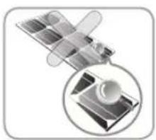
natural_image
Illustration of a satellite with its open lens and internal components, shown in two circular views (no text or symbols)
Partial shadow must be removed from solar module because it can cause severe problems of solar module.

natural_image
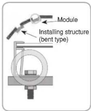
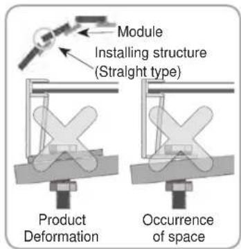
Illustration of a cross-shaped object with a tree and leaf on top, no text or symbols presentIf the installing modules on curved surface, (e. g. arch type), as shown in the below picture, do not forcefully modify the module in the installation when connecting it with the structure. Only install the module in the place where the structure for the panels has been properly set up. An improper structure may cause deformation of the panels. Panels may also be damaged by unapproved installation methods such as the use of a crane.
BEFORE & AFTER INSTALLATION
Before Installation
Please carefully read this manual before installation.
- Solar module installation and maintenance must be performed by qualified and authorized installer.
- All installation instructions should be read and understood before performing any installation.
- Do not touch the solar module with bare hands. It may result in a burn or injury.
- Do not disassemble the solar module.
- After installation or repair, check that the solar module are operating properly.
- In the event that the currently used solar module or parts have been replaced the newly replaced module and parts must have the same model name and parts as the previously installed solar module.
- Do not let anyone approach the solar module who has little knowledge of solar modules or on the measures to take when solar modules are damaged in order to avoid the risk of injury or electrical shock.
- Secure all necessary permits and licenses to install the solar modules.
- Do not locate the solar module horizontally, as this may cause dirt or white efflorescence(glass deformation).
- Panels are not intended for use indoors or on moving vehicles of any kind.
- Industry standard rated specifications are made at conditions of 1000W/m^2 irradiance and 25^ ( 77^ ) solar cell temperature. Colder temperatures may substantially increase voltage and power.
- Keep the solar module and system away from children at all times.
- Keep the module packed in the carton until the time of installation.
- Keep flammable gasses away from the installation site.
- Do not work alone. Please work as part of a team of two or more people.
- Safety harness use is strongly recommended for installation.
- Be careful not to damage the cable when using a tool such as a knife to remove the cable tie that fixes the junction box cable.
- Partial shadowing may substantially reduce panel and system output and may be the reason for the damage of solar module.
- Care must be taken to avoid low tilt angles which may cause dirt to buildup on the glass against the frame edge.
- Dirt build-up on the surface of the panel may cause active solar cells to be shaded and electrical performance to be impaired.
After Installation
- Plug in the connector tightly and ensure that the wiring properly works.
- Conduct periodic inspection of the panels for damage to front glass, back sheet, frame, junction box, or external electrical connections.
- Check electrical connections for loose connections and corrosion.
- PV panels can operate effectively without ever being washed, although removal of dirt from the front glass can increase output.
- Water, ethanol or a conventional glass cleanser with a micro-fiber cloth can be used for regular washing or rinsing of the front glass to remove dust, dirt or other deposits.
- Do not use ground water containing calcium carbonate components when cleaning glass.
- Aggressive and abrasive cleansers or chemicals such as alkali chemicals including ammonia based solution should not be used on cleaning the module.
- Always keep the back surface of the panel free from any foreign objects or structural elements which could come into contact with the panel, especially when the panel is under mechanical load.
- Deposits of foreign material on the frame surface can be cleaned by using a wet sponge or cloth and dried in air or by using a clean chamois.
- Perform the wiring work by connecting the connector and wires to the stand away from the roof or ground.
- Do not use any kind of oil or lubricant on the module's any parts, It can defect the PV Module.
ELECTRICAL INSTALLATION
Caution
- Avoid all electrical hazards when installing, wiring, operating and maintaining all panels.
- Do not connect panels that have different electrical properties or physical configurations in the same system.
- Match the polarities of cables and terminals when making the connections; failure to do so may result in damage to the panel.
- When reverse currents can exceed the value marked on the name plate, a properly rated and certified over-current device(fuse or circuit breaker) must be connected in series with each panel or string of panels.
- The rating of the over-current device shall not exceed the maximum series fuse rating marked on the name plate.
- The panel contains factory installed bypass diodes located inside the junction box.
- When installing the system, it is recommended to install a lightning rod to protect the system.
- The induced overvoltage by lightning can cause the system damage, you should design conductor loop connection as minimum as possible.
- The junction box should not be opened. Opening the junction box will void the warranty.
- Panels with a suspected electrical problem should be returned to LG Electronics for inspection and possible repair or replacement as per the warranty conditions provided by LG Electronics.
Electrical Connections
- Shock hazard may occur near the solar modules electrical connections.
- Modules may be connected in series and/or parallel to achieve the desired electrical output as long as it is within the guidelines on the product specification sheet.
- Please use only the same type of modules in a combined source circuit.
- Do not disconnect the module under when it is operating. Shock hazard may occur near the solar modules connection means.
- When the module installing in series or in parallel (e.g. using for extension cables, etc.), the connector of each module should be the same products. (mated with its original female or male connector of the same supplier)
Diodes
- All LG modules are equipped with factory installed bypass diodes. The factory-installed diodes provide proper circuit protection for the module from unexpected shadows.
| I_F (AV) 25A | |
| V_F (max) 0.6V | |
| V_RRM 50V | |
| T_J (max) | 200°C |
| R_TH 2.0°C/W |
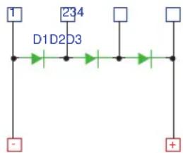
Diode specification and configuration
Series Connection
- The solar modules may be wired in series to produce the desired voltage output.
- The current of each module connected in series should be the same.
- The maximum number of series connected modules can be determined by basis on maximum system voltage, the 125% safety factor, and the module Voc which can be checked in “Product Specifications” in this document.
- The maximum solar module configuration can be found in "Product Specifications".
Series connection for more voltage
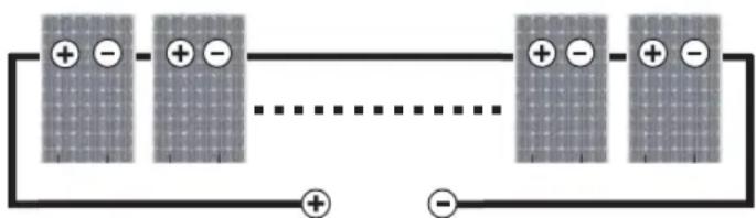
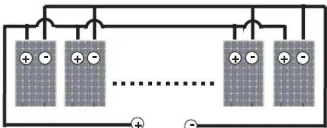
Parallel Connection
- The solar modules may be combined in parallel to produce the desired current output.
- When modules are combined in parallel, the total current is equal to the sum of currents from each module.
- The voltage of each module connected in parallel should be the same.
- When connecting plural strings of modules in parallel every series string or solar module must be fused prior to combining with other strings.
- Abide with all applicable federal, state, and local codes for additional fusing requirements and limitations on the maximum number of solar modules in parallel.
- Maximum series fuse rating is refer to "Product Specifications; page 11".
- Parallel configuration is not limited if proper measures are taken to block the reverse current flow, e.g. fuses for the protection of the module and cables from over-current for prevention of unbalanced string voltage.
- A multiplying factor is required for increased output of the PV modules. Under normal conditions, a PV module is likely to experience conditions that produce more current and/or voltage than reported at standard test conditions. The requirements of the National Electrical Code (NEC) in Article 690 shall be followed to address these increased outputs. In installations not under the requirements of the NEC, the values of Isc and Voc marked on this PV module should be multiplied by a factor of 125% when determining component voltage ratings, conductor ampacities, fuse sizes, and size of controls to the PV output.
- Depending on national directives, additional safety factors might be applicable for over current protection.
natural_image
Pure electrical circuit lines without any symbolsParallel connection for more current
General Wiring
- LG Electronics recommends that all wiring be double insulated with a minimum rating of 90°C (194°F).
- All wiring should use a flexible copper (Cu) conductor.
- The minimum size should be determined by the applicable codes.
- LG Electronics recommends a size no smaller than 4mm^2 .
Earth Grounding
- All work must be conducted in conformance with all Federal, State, and local codes and standards.
- Grounding works should be performed by an authorized installer for the safety and maintenance of the system in accordance with all national, state and local electrical codes and regulations and standards.
- Specific information on the solar module dimensions and location of grounding holes is provided in “Product Specifications”.
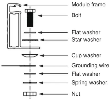
- One M4 stainless steel bolt, one nut, one spring washer, two flat washers, one cup washer, one star washer and 12 AWG Cu wires are recommended per mounting hole.
- Where common grounding hardware (nut, bolts, washers) is used to attach a listed grounding device, the attachment must be made in conformance with the grounding device manufacturer's instructions.
- All hardware should be consist of corrosion resistant material such as stainless steel.
- There is an earth hole on the edge of the module frame. Using this hole, an earth conductor and the solar module frame may be recommended to be connected and earthed as the below drawing.
- All screws and nuts shall be tightened to a torque of 4\~5 N·m.
- To prevent electric shock and fire, a protective ground must be done on the frames of solar modules and arrays although the solar modules from LG meet the conditions of safety class II. The national directives must be respected.
MECHANICAL INSTALLATION
Module Mounting
- The LG Electronics' (LGE) Limited Warranty for solar modules is contingent upon modules being mounted in accordance with the requirements described in this section.
- The solar modules are in Application Class A and have the Safety Class II. Therefore they can be operated in systems with 120V DC and higher. General access is not restricted.
- We recommend to use mounting device(bolt, nut, washer) made by corrosion resistant material like stainless steel.
Site Consideration
LGE solar modules should be mounted in a location that meets the following requirements.
Operating Temperature
• Maximum Operating Temperature: +90°C (194°F)
• Minimum Operating Temperature: -40°C (-40°F)
Excluded Operating Environments
- The solar modules from LG Electronics can not be operated in a location where they could come in direct contact with salt water or ammonia.
Module Strength(Basic Load) ; IEC61215-2:2016
| No. of Cell | Force Direction | Design Load : A | Test Load : B ( B = A × Y_m) |
| 60Cell | 3600 PascalFront | 5400 Pascal | |
| Rear Side | 2650 Pascal | 4000 Pascal |
- Y_m is a safety factor of 1.5
• Detail of mounting distance is below.
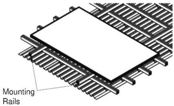
※ This mounting method is by using frame bolt holes.
※ The mounting rails must run perpendicularly to the module long side.
Shadow
- LGE solar module should be installed in a proper site that there is no shadowing affected by building, chimney, tree, and neighboring module, etc.
- Use corrosion resistant material mounting rails and hardware.
- Use appropriate bolted connections as per manufacturer's instructions.
- No electrical parts like cables are located after installation between laminate and mounting structure.
• LGE solar module is qualified up to a altitude of 4000m.
Mounting Methods
General Information
- Select the appropriate orientation to maximize sunlight exposure.
- Module should not be mounted or stored in a way that the front/top glass faces downward in order to prevent water from entering the junction box, which could cause a safety hazard.
- Clearance between the solar module frames and structures such as roofs or ground is required to prevent wiring damage and to allow air to circulate behind the solar module. The recommended standoff height is a minimum of 100mm.
- When installed on a roof, the solar module must be mounted over a fire-resistant roof covering rated for the application. The fire resistance of the solar module is class C after ANSI/UL790 Edition 2004.
- The solar module is only IEC listed for use when its factory frame is fully intact.
- Removal or alteration must be done by an authorized and qualified individual.
- Creating additional mounting holes may damage the solar module and reduce the strength of the frame.
-
We recommend a 6mm gap between module frames to avoid tension from thermal expansion.
-
The solar module may be mounted by using the following methods: (*Torque:8\~12N·m)
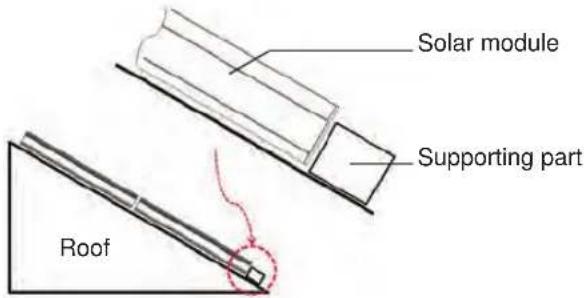
- When installing modules in heavy snow areas, it is recommended to be taken an appropriate countermeasure to prevent possible damages to the lower side frame by slipping snow.
- We recommend to use corrosion resistant material for these supporting part. (A snow guard should be installed in accordance with the manufacturer's instructions.)
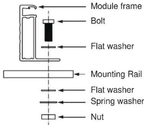
Mounting by using frame bolts holes
- Secure the solar module to the structure by using the factory mounting holes.
- Four M8 stainless steel bolts, four nuts, four spring washers, and eight flat washers are recommended per solar module.
- The module may be fastened to a support by using both the outer and inner bolt holes of the frame.
- Each module should be securely fastened at a minimum 4 points on two opposite sides.
- Specific information on the solar module dimensions and location of mounting holes is provided in 'Product Specifications'.
- Tighten the bolt securely by using the combination. Place the spring washer between the Flat washer and Nut.
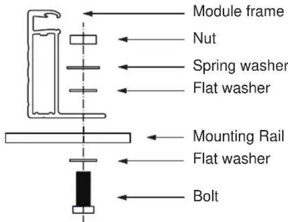
* Mounting Rails Material : Aluminum, Stainless steel, etc. → We recommend more than 40x40mm mounting rails.
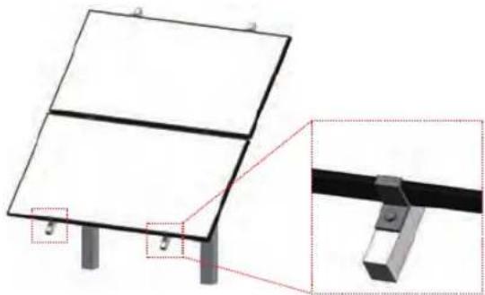
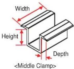
Mounting by using clamps
- The module may be fastened to a support by using clamps on both the long edge and the short edge of the modules.
- Specific information on location of clamping is provided in 'Mechanical Installation Scene'. (Refer to Appendix.)
→ If you use a special clamp, it needs to test for compatibility by LGE.
- If the installation is likely to be affected by heavy(extreme) snow, further suitable panel support is recommended on the lower row of panels.
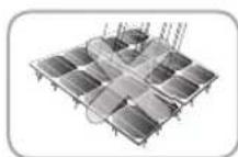
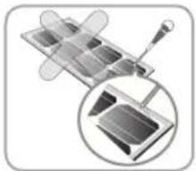
natural_image
Technical diagram of a solar panel mounted on a metal frame, showing structural components and mounting points (no text or symbols)DISCLAIMER OF LIABILITY / DISPOSAL
Disclaimer of Liability
- By beginning to installation process, the installer has to read and completely understand this Installation Manual.
- If installer had any questions regarding this installation manual, the installer would have contacted LG with any questions or concerns.
- By installing an LG Solar module, I discharge, and covenant not to sue LG, its affiliated companies, successors, or assigns, its administrators, directors, agents, officers, volunteer and employees, other participants in any activity connected to installation, operation, or service of LG Solar Modules, and if applicable, from all liabilities, claims, demands, losses, or damages on my account caused or alleged to be caused in whole or in part by the negligence of the LG its affiliated companies, successors, or assigns, its administrators, directors, agents, officers, volunteer and employees.
Disposal
Disposal of your old appliance
- This crossed-out wheeled bin symbol indicates that waste electrical and electronic products(WEEE) should be disposed of eparately from the municipal waste stream.
- Old electrical products can contain hazardous substances so correct disposal of your old appliance will help prevent potential negative consequences for the environment and human health. Your old appliance may contain reusable parts that could be used to repair other products, and other valuable materials that can be recycled to conserve limited resources.
- You can take your appliance either to the shop where you purchased the product, or contact your local government waste office for details of your nearest authorized WEEE collection point. For the most up to date information for your country please see www.lg.com/global/recycling materials that can be recycled to conserve limited resources.
natural_image
Symbol of a trash bin crossed with no visible text or numbersTRANSPORTING AND STORAGE
- Do not loosen the banding, when the module is transported by truck, ship and etc. In case of loose banding, the module will be shaken, which may cause damage.
- Do not stack on more than one pallet. Maximum height is two pallets. Severe stacking can cause stress to the module and may cause product damage.
- Do not transport only one side of the module when transporting the module. Damage to the frame or cable may occur.
REVISIONS TABLE
| Date Version | Description of change | Remark | |
| 2018.10.10 1.0 | (1 st edition) | Publish Installation Manual | |
| 2019.02.13 2.0 | Adding a new model (Q1K-V5) | ||
| 2019.04.15 3.0 | Adding a new model (Q1C-V5) | ||
| Adding a new model (Q1C-V5)2020.02.03 | 4.0 | ||
PRODUCT SPECIFICATIONS
Rated electrical characteristic except power rating within -0/+3 percent are within 5 percent of measured.
Values at Standard Test Condition(STC) : Irradiance 1000W/m², Cell temp. 25°C, 1.5AM
| Electrical Properties | Mechanical Properties | ||||||||||||||
| Module Series | Model Name | Pmax at STC | Power Tolerance | Voc at STC | Isc at STC | Vmpp at STC | Impp at STC | Max. No. of module in series | Max. Series Fuse Rating | Max. System Voltage | Connector | Length | Width | Height | Weight |
| W | % | V | A | V | A | A | V | mm | mm | mm | kg | ||||
| LGXXXQ1C-V5 | LG330Q1C-V5 | 330 | 0~3% | 42.5 | 10.73 | 35.2 | 9.38 | 18 | 20 | 1000 | MC4/JM608 | 1700 | 1016 | 40 | 17.5 |
| LG335Q1C-V5 | 335 | 0~3% | 42.6 | 10.74 | 35.4 | 9.47 | 18 | 20 | 1000 | MC4/JM608 | 1700 | 1016 | 40 | 17.5 | |
| LG340Q1C-V5 | 340 | 0~3% | 42.6 | 10.75 | 35.6 | 9.56 | 18 | 20 | 1000 | MC4/JM608 | 1700 | 1016 | 40 | 17.5 | |
| LG345Q1C-V5 | 345 | 0~3% | 42.6 | 10.76 | 35.8 | 9.64 | 18 | 20 | 1000 | MC4/JM608 | 1700 | 1016 | 40 | 17.5 | |
| LG350Q1C-V5 | 350 | 0~3% | 42.7 | 10.77 | 36.1 | 9.70 | 18 | 20 | 1000 | MC4/JM608 | 1700 | 1016 | 40 | 17.5 | |
| LG355Q1C-V5 | 355 | 0~3% | 42.7 | 10.78 | 36.3 | 9.79 | 18 | 20 | 1000 | MC4/JM608 | 1700 | 1016 | 40 | 17.5 | |
| LG360Q1C-V5 | 360 | 0~3% | 42.7 | 10.79 | 36.5 | 9.87 | 18 | 20 | 1000 | MC4/JM608 | 1700 | 1016 | 40 | 17.5 | |
| LG365Q1C-V5 | 365 | 0~3% | 42.8 | 10.80 | 36.7 | 9.95 | 18 | 20 | 1000 | MC4/JM608 | 1700 | 1016 | 40 | 17.5 | |
| LG370Q1C-V5 | 370 | 0~3% | 42.8 | 10.82 | 37.0 | 10.01 | 18 | 20 | 1000 | MC4/JM608 | 1700 | 1016 | 40 | 17.5 | |
| LG375Q1C-V5 | 375 | 0~3% | 42.8 | 10.83 | 37.2 | 10.09 | 18 | 20 | 1000 | MC4/JM608 | 1700 | 1016 | 40 | 17.5 | |
| LG380Q1C-V5 | 380 | 0~3% | 42.9 | 10.84 | 37.4 | 10.17 | 18 | 20 | 1000 | MC4/JM608 | 1700 | 1016 | 40 | 17.5 | |
| LGXXXQ1K-V5 | LG350Q1K-V5 | 350 | 0~3% | 42.9 | 10.39 | 36.2 | 9.68 | 18 | 20 | 1000 | MC4/JM608 | 1700 | 1016 | 40 | 17.5 |
| LG355Q1K-V5 | 355 | 0~3% | 43.1 | 10.44 | 36.4 | 9.76 | 18 | 20 | 1000 | MC4/JM608 | 1700 | 1016 | 40 | 17.5 | |
| LG360Q1K-V5 | 360 | 0~3% | 43.3 | 10.50 | 36.7 | 9.82 | 18 | 20 | 1000 | MC4/JM608 | 1700 | 1016 | 40 | 17.5 | |
| LG365Q1K-V5 | 365 | 0~3% | 43.5 | 10.55 | 36.9 | 9.90 | 18 | 20 | 1000 | MC4/JM608 | 1700 | 1016 | 40 | 17.5 | |
| LG370Q1K-V5 | 370 | 0~3% | 43.7 | 10.61 | 37.2 | 9.97 | 18 | 20 | 1000 | MC4/JM608 | 1700 | 1016 | 40 | 17.5 | |
Note) MC4 formal name : PV-KST4 / 6II-UR, PV-KBT4 / 6II-UR
→ Plus (+) Connector : Male MC4 coupler (PV-KST4/6II-UR)
→ Negative (-) Connector : Female MC4 coupler (PV-KBT4/6II-UR)
Note) The Typical change in module efficiency at 200W/m^2 in relation to 1000W/m^2 is -6.0% (Min. -8.0%)
"Max. No. of modules in series" is considering 125% of Voc. Actual number of connections should be selected according to the installation site conditions and local code.
◇ Female and male cable couplers ◇
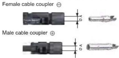
| Model | Cable Cross Section | ∅ A (Cable outer diameter) | Rated current |
| MC4 | 4mm^2 | 5.5 ~ 9mm | 30A |
| 12AWG | |||
| JM608 | 4mm^2 | 5.4 ~ 7.2mm | 30A |
| 12AWG |
※ See more information >> http://www.multi-contact.com/ or http://www.jmthy.com/
Electrical Properties(NMOT*)
| Model | LGXXXQ1C-V5 | LGXXXQ1K-V5 | |||||||||||||||
| 330 | 335 | 340 | 345 | 350 | 355 | 360 | 365 | 370 | 375 | 380 | 350 | 355 | 360 | 365 | 370 | ||
| Maximum Power (Pmax) [W] | 256 | 248.4 | 252.2 | 259.8 | 263.5 | 267.2 | 271.1 | 274.7 | 278.7 | 282.4 | 286.2 | 263.6 | 267.3 | 271.2 | 274.9 | 278.7 | |
| MPP Voltage (Vmpp) [V] | 35 | 35.0 | 35.3 | 35.7 | 36.0 | 36.2 | 36.4 | 36.6 | 36.9 | 37.1 | 37.3 | 36.1 | 36.3 | 36.6 | 36.8 | 37.1 | |
| MPP Current (lmpp) | [A] | 7.11 | 7.17 | 7.21 | 7.27 | 7.32 | 7.39 | 7.45 | 7.51 | 7.55 | 7.61 | 7.67 | 7.30 | 7.36 | 7.41 | 7.47 | 7.53 |
| Open Circuit Voltage (Voc) | [V] | 40.0 | 40.1 | 40.1 | 40.1 | 40.1 | 40.2 | 40.2 | 40.2 | 40.3 | 40.3 | 40.3 | 40.4 | 40.6 | 40.8 | 41.0 | 41.2 |
| Short Circuit Current (Isc) | [A] | 8.65 | 8.66 | 8.66 | 8.67 | 8.67 | 8.68 | 8.69 | 8.70 | 8.71 | 8.72 | 8.73 | 8.37 | 8.41 | 8.46 | 8.50 | 8.55 |
* NMOT (Nominal Module Operating Temperature): Irradiance 800W/m ^2 , ambient temperature 20°C, wind speed 1m/s
Temperature Characteristics
| Model | LGXXXQ1C-V5 | LGXXXQ1K-V5 | |
| NMOT [ °C ] | 44 ± 3 | 44 ± 3 | |
| Pmax [%/°C] -0.30 | -0.30 | ||
| Voc [%/°C] -0.24 | -0.24 | ||
| Isc [%/°C] 0.037 | 0.037 | ||
Dimensions of Modules
Unit: mm / in.
LGXXXQ1C(K)-V5
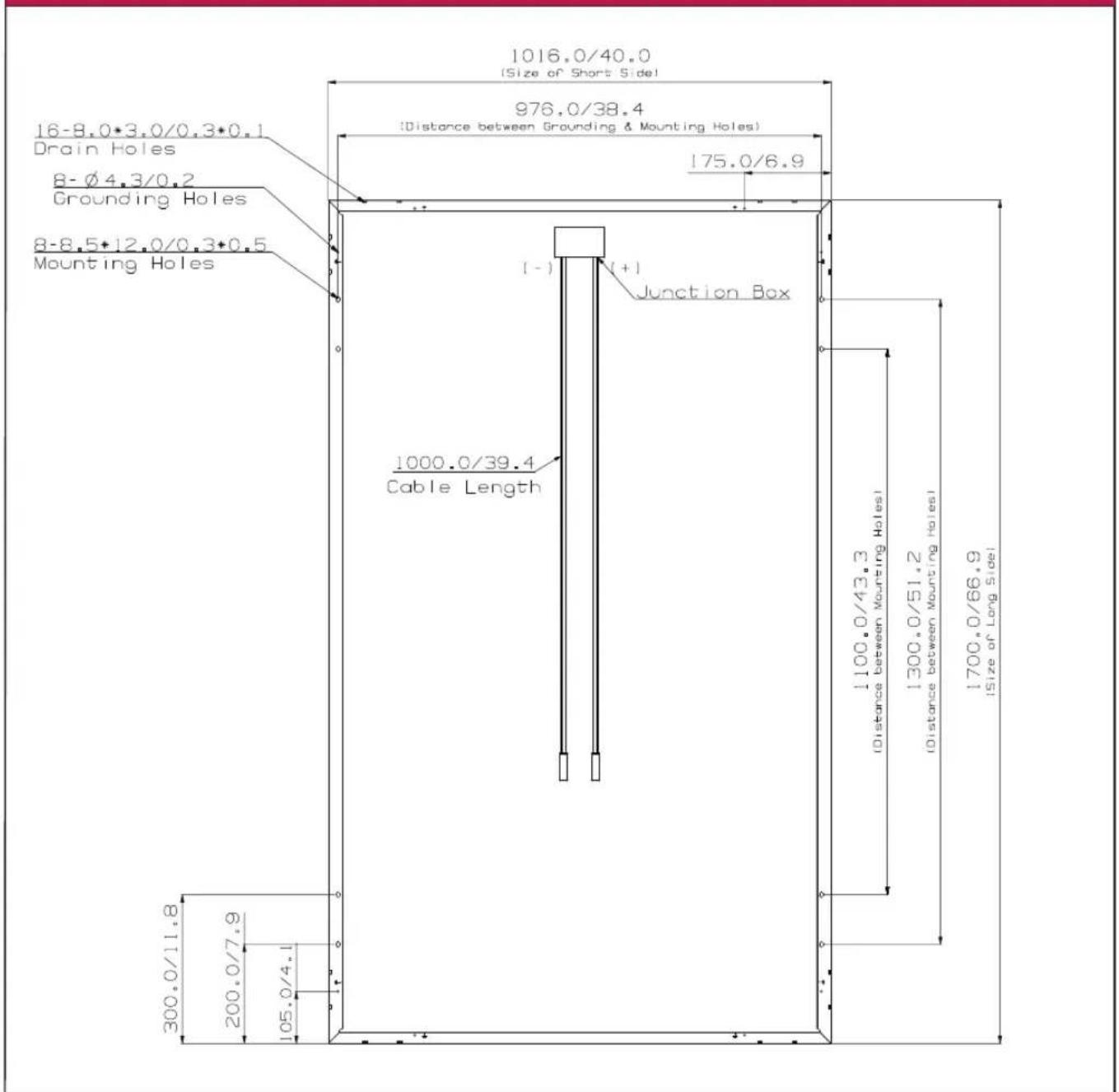
Note) Cable length with connector (JM608)
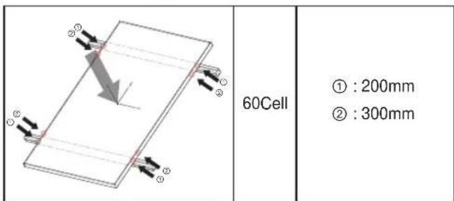
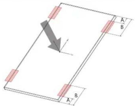
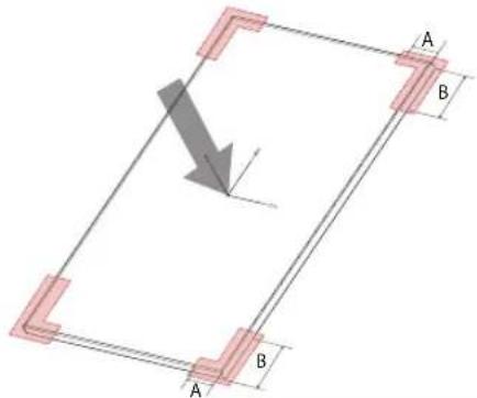
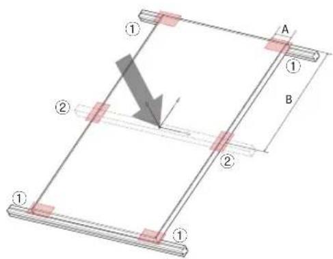
Mechanical Installation : 60Cell Model
Fig.1 Bolting Type Fig.2 Clamping Type
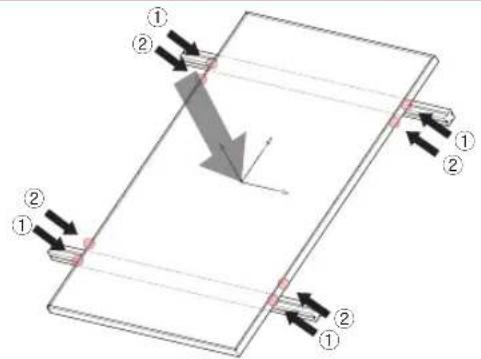
①:200mm
②:300mm
Front : 5400Pa
Rear : 4000Pa
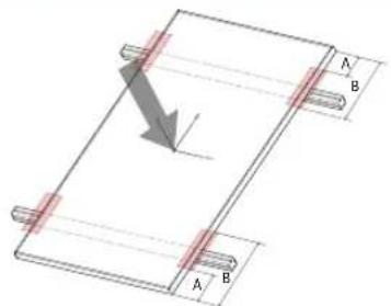
A:200mm
B:400mm
Front : 5400Pa
Rear : 4000Pa
A:0mm
B : 650mm
Front : 2400Pa
Rear : 2400Pa
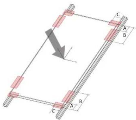
Fig.3 Clamping Type Fig.4 Clamping Type
A:200mm
B:400mm
Front : 4000Pa
Rear : 4000Pa
A:200mm
B:200mm
Front : 1800Pa
Rear : 1800Pa
Front:2400Pa
Rear : 2400Pa
Fig.5 Clamping Type Fig.6 Clamping Type
A:200mm
B:400mm
Front : 5400Pa
Rear : 4000Pa
A : 120mm
*4point(①)
Front : 1800Pa
Rear : 1800Pa
C:120mm
Front : 5400Pa
Rear : 1800Pa
A:120mm
B:843±100mm
6point(①+②)
Front : 5400Pa
Rear : 4000Pa
Bolting Method
- Four M8(5/16inch) stainless steel bolts, four nuts, four spring washers, and eight flat washers are recommended per solar module.
Clamp system requirements
- The clamp should not be touched with the module's glass.
- Use corrosion resistant material clamps and hardware.
→ If you use a special clamp, it needs to test for compatibility by LGE.
- Use appropriate bolted connections as per clamp manufacturer's instructions.
- Follow the clamp manufacturer's recommended applied torque to fasten the clamps.
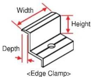
Unloading Flow Guide
If you are unloading using heavy equipment such as a crane, please follow the procedure below.
[Step 1] [Step 2] [Step 3] [Step 4]
Step 1. Place the packaging on a flat surface.
Step 2. Put the safety timber bar on the packaging and fasten a rope as shown Fig. [Step 2]
- To prevent module breakage, you should use safety timber bar bigger than packaging length.
- The position of rope have to be between block 1 and block 2 when you fasten a rope to pallet.
- Detailed view of the rope position is below.
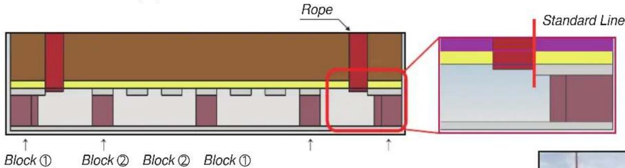
- If you have not timber bar, you can use a pallet which is longer than module size.
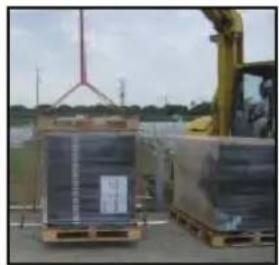
Step 3. Loading & unloading packaging.
- The crane hook have to be placed center of packaging.
- For the balance of packaging, the rope between the packaging and crane must be the same length.
Step 4. Landing packaging on a floor.
- A minimum of two operator is required to ensure that all four corners are seated at the same time when the packaging is unloaded.
▶ If you need some question or advice of this, please contact our sales manager.
natural_image
Packed pallets with visible shipping containers and a yellow excavator in the background (no text or symbols)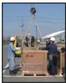
natural_image
Workers in hard hats handling a box on a pallet under a crane, with electrical equipment and power lines in the background (no visible text or symbols)
LG
Life's Good
LG Twin Towers, 128, Yeoui-daero, Yeongdeungpo-gu,
Seoul 07336, Korea
Contact: solar-svc@lge.com
http://www.lg-solar.com
This document is subject to change without notice.
LG, LG logo and Life's Good are trademarks of LG Electronics, Inc. worldwide. Trademarks and intellectual properties of LG Electronics, Inc. are protected by international copyright laws.
- TABLE OF CONTENTS
- SAFETY 03
- BEFORE & AFTER INSTALLATION 05
- ELECTRICAL INSTALLATION 06
- MECHANICAL INSTALLATION 08
- DISCLAIMER OF LIABILITY / DISPOSAL ......10
- TRANSPORTING AND STORAGE 10
- REVISIONS TABLE 10
- PRODUCT SPECIFICATIONS ....11
- APPENDIX....13
- SAFETY
- DANGER
- WARNING
- CAUTION
- BEFORE & AFTER INSTALLATION
- Before Installation
- After Installation
- ELECTRICAL INSTALLATION
- Electrical Connections
- Diodes
- Series Connection
- Parallel Connection
- General Wiring
- Earth Grounding
- MECHANICAL INSTALLATION
- Module Mounting
- Site Consideration
- Operating Temperature
- Excluded Operating Environments
- Shadow
- Mounting Methods
- General Information
- Mounting by using frame bolts holes
- Mounting by using clamps
- DISCLAIMER OF LIABILITY / DISPOSAL
- Disclaimer of Liability
- Disposal
- Disposal of your old appliance
- TRANSPORTING AND STORAGE
- PRODUCT SPECIFICATIONS
- Dimensions of Modules
- Mechanical Installation : 60Cell Model
- Bolting Method
- Clamp system requirements
- Unloading Flow Guide
- LG
- Life's Good
Brand : LG
Model : Neon R Prime 360Q1K-V5
Category : Installation solaire