
VPD 150 - Instant water heater and water tank Nibe - Free user manual and instructions
Find the device manual for free VPD 150 Nibe in PDF.


| Product Type | Heat pump water heater & storage tank |
| Model | VPD 150 |
| Brand | Nibe |
| Storage Volume | 150 liters |
| Dimensions (Diameter x Height) | 600 mm x 1650 mm |
| Weight (empty) | 110 kg |
| Power Supply | 230 V / 50 Hz / 1-phase |
| Heating Element Power | 2.25 kW (electric backup) |
| Compressor Power | 0.8 kW |
| COP (at A7/W35) | 3.4 |
| Max Water Temperature | 65 °C |
| Max Operating Pressure | 1.0 MPa (10 bar) |
| Refrigerant Type | R407C |
| Sound Level (LwA) | 48 dB(A) |
| Energy Efficiency Class | A+ |
| Main Functions | Domestic hot water heating, heat pump operation, electric backup, anti-legionella cycle |
| Maintenance Tasks | Annual cleaning of air filter, inspection of anode, pressure relief valve test |
| Safety Features | Overheat protection, pressure relief valve, frost protection |
| Spare Parts & Repairability | Replaceable magnesium anode, thermostat, compressor, fan |
| General Information | Indoor installation, requires ventilation, suitable for up to 4-person household |
Frequently Asked Questions - VPD 150 Nibe
User questions about VPD 150 Nibe
0 question about this device. Answer the ones you know or ask your own.
Ask a new question about this device
Download the instructions for your Instant water heater and water tank in PDF format for free! Find your manual VPD 150 - Nibe and take your electronic device back in hand. On this page are published all the documents necessary for the use of your device. VPD 150 by Nibe.
USER MANUAL VPD 150 Nibe
natural_image
Two cylindrical industrial tanks with copper fittings, one larger and one smaller, shown from different angles (no text or symbols visible)User and Installer manual
VPD 150, 300
Water heater Accumulator tank
Table of Contents
41 Important information
62 For the User
73 For the Installer
124 Technical data
15Contact information
1 Important information
Safety information
This manual describes installation and service procedures for implementation by specialists.
This appliance can be used by children aged from 8 years and above and persons with reduced physical, sensory or mental capabilities or lack of experience and knowledge if they have been given supervision or instruction concerning use of the appliance in a safe way and understand the hazards involved. Children shall not play with the appliance. Cleaning and user maintenance shall not be made by children without supervision.
Rights to make any design or technical modifications are reserved.
©NIBE 2017.
General
es Serial number
The serial number can be found on top of the product.

Caution
Always give the product's serial number when reporting a fault.
Recovery

Leave the disposal of the packaging to the installer who installed the product or to special waste stations.
Do not dispose of used products with normal household waste. It must be disposed of at a waste station or dealer who provides this type of
Improper disposal of the product by the user results in administrative penalties in accordance with current legislation.
Country specific information
User and Installer manual
This user and installer manual must be left with the customer.
Symbols

NOTE
This symbol indicates danger to person or machine.

Caution
This symbol indicates important information about what you should observe when maintaining your installation.

TIP
This symbol indicates tips on how to facilitate using the product.
Inspection of the installation
Current regulations require the heating installation to be inspected before it is commissioned. The inspection must be carried out by a suitably qualified person.
| √ | DateSignat | |||
| Hot water (page 9) | ||||
| Shut off valves | ||||
| Cold water (page 9) | ||||
| Shut off valves | ||||
| Non-return valve | ||||
| Mixing valve | ||||
| Safety valve | ||||
| Electricity (page 11) | ||||
| Sensors | ||||
2 For the User
Maintenance
Safety valve (not supplied)
The safety valve must be inspected regularly, about 4 times a year, to prevent blockages. To inspect the valve, open the safety valve manually and check that water flows through the overflow pipe. If this does not happen, the safety valve is defective and must be replaced.
The safety valve sometimes releases a little water after hot water has been used. This discharge is caused by the expansion of cold water entering the water heater, resulting in a pressure increase, whereby the safety valve opens.
Emptying
- Shut off the incoming cold water.
- Open the drain connection, or the drain valve if fitted.
During draining, air must be let into the water heater by loosening a hot water connector (XL4) or opening a hot water tap.
To ensure that the water heater drains completely, a hose, or a pipe, with an outlet below the lowest level of the water heater must be attached to the drain connection or drain valve. When installed in a location that is exposed to the risk of frost, the water heater must be emptied whenever it is not in operation. Freezing will result in the water heater bursting.
Service
For service, contact the installer. Serial number (PF3) (14 digits) and installation date should always be stated.
Only replacement parts supplied by NIBE may be used.
3 For the Installer
General
Supplied components
VPD is a water heater, which is suitable for connection to heat pumps.
The water tank has internal stainless steel corrosion protection.
The water heater is designed and manufactured for a maximum cut-off pressure of 10 bar. Maximum permitted temperature is 95 °C.
The insulation is polyurethane, which provides excellent heat insulation. The outer shell on VPD is grey plastic.
VPD is equipped with submerged tube for control of 1hot straight G15/22 connec-x straight G15/15 connec-water heating. tion

natural_image
Technical line drawing of a mechanical component with threaded top and flanged base (no text or symbols)
Transport
VPD should be transported and stored vertically in a place. The VPD may, however, be carefully laid on its back when being moved into a building.

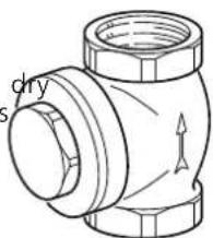
natural_image
Technical line drawing of a pipe fitting with no text or symbols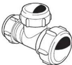
natural_image
Line drawing of a T-junction pipe fitting with flanges and central hub (no text or symbols)1 x G15 non-return valve1 x 28/22/22 T-coupling

natural_image
Four different types of pipe fittings shown in line drawings, no text or symbols present.Assembly
The water heater is only designed for upright installation _x 22/15 connections. The water heater's installation area should always have a temperature of at least 10 °C (frost-free).
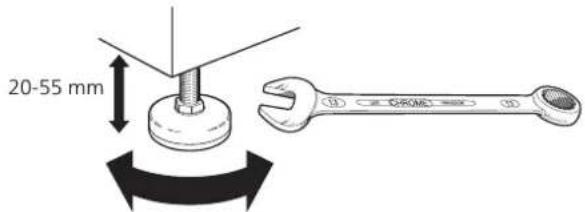
Position VPD on a firm base that can take the weight, preferably on a concrete floor or foundation. Use the product's adjustable feet to obtain a horizontal and stable set-up.
The area where VPD is located must be equipped with floor drainage.
2 x straight 22/15 coup- lings
Component positions

Pipe connections
Connection, cold water, blue (28 mm)XL3
Connection, hot water, red (22 mm)XL4
Connection, supply line from HP, white (22 mm)XL36
Miscellaneous
Rating platePF1
Serial number platePF3
Designations in component locations according to standard IEC 81346-1 and 81346-2.
HVAC components
Submerged tube for hot water sensor (display)UA1
Submerged tube for hot water sensor (control)UA2
Pipe installation
The enclosed kit includes suitable connectors that can be used for the installation.
Pipe installation must be carried out in accordance with current norms and directives.
The water heater must be fitted with the necessary valves, such as a safety valve, shut-off valve and non-return valve.
The water heater must be provided with a mixer valve, which limits the temperature of outgoing hot water to 60 °C. If this valve is not fitted, some other measure must be taken to prevent the risk of scalding.
Internal support bushes must be fitted when a plastic or annealed copper pipe is used. An overflow pipe must be routed from the safety valve to a suitable drain. The overflow pipe must be the same size as the safety valve. Route the overflow pipe from the safety valve, sloping along its entire length and ensure that it is frost proof. The mouth of the overflow pipe must be visible and not placed close to electrical components.
| Connection | ||
| 28mr | ||
| 22mr | ||
| 22mr |

Heat pump
Connecting to heat pump
The heat pump supply and return are connected to
L36 Supply line 0 Install the T-coupling in position (XL3) (blue) as illustrated.
- Connect the return line from the heat pump to the angled connection on the T-coupling. Install the supplied non-return valve on this pipe.
VPPdstall a shut-off valve on the incoming cold water pipe.
- The safety valve must have a maximum 10.0 bar opening pressure and be installed on the incoming cold water line. The entire length of the overflow water pipe from the safety valves must be inclined, to prevent water pockets and must also be frost-free.
■ Connect the incoming cold water to the T-coupling. - Angled couplings, 22/15 mm, installed on connections (XL4) and (XL36) as illustrated.
■ Connect the supply line from the heat pump to pos (XL36) (white) on the water heater section.
■ Hot water connection to pos (XL4) (red) on the water heater.

flowchart
graph TD
    A["Supply line hp"] --> B["Heat Exchanger"]
    C["Return line hp"] --> B
    D["Cold water"] --> B
    B --> E["Hot water"]
Schematic diagram
Cold and hot water
Connecting cold and hot water
There must be a mixer valve if the temperature can ceed 60 °C.

natural_image
Pure diagram of a vertical cylindrical tank with internal piping and valves, no text or symbols presentSchematic diagram
Symbol key
| MeaningSymbol | |
| Shut-off valve | |
| Mixing valve | |
| Safety valve | |
| Temperature sensor | |
| Particle filter |
Installation alternative
VPD can be connected in several different ways, one of which is shown here.
Further option information is available at www.nibe.eu and in the respective assembly instructions for the heat sources used.
To exhaust air heat pump
VPD can be docked with heat pump, for example NIBE exhaust air heat pump.

Filling
Fill the water heater as follows:
- Open a hot water tap in the system.
- Fill the hot water heater through the cold water connection (XL3).
- The hot water tap can only be shut off when the water heater is filled, which is when only water comes out of the tap (initially an air-water mixture comes out of the tap).
Electrical installation
NOTE Electr
Electrical installation and service must be carried out under the supervision of a qualified electrician, and in accordance with applicable electrical safety regulations.
^1 VPD can be supplemented with up to two hot water sensors, one for display and one for control. The display sensor is positioned in the submerged tube for the display sensor (UA1) and the control sensor is positioned in the submerged tube for the control sensor UA2. In cases where it is only possible to connect one sensor, use the submerged tube for the control sensor (UA2).
Use the sensors provided with the heat pump (or other heat source). When no heat sensors have been provided these must be ordered from the manufacturer of the heat source.
4 Technical data
Dimensions

Technical specifications
| VPD10 300RV | |||
| 1623-1643914-934mmHeig | |||
| 596596mmDiameter | |||
| 7551kgNet weight | |||
| Max pressure, water heater | bar/MPa | 10/1.0 | |
| Max water temperature | °C | 95 | |
| mm | Connect 202, hot water (red) | ||
| Connection, cold water/ HP return (blue) | mm | 28 | 28 |
| Connection, HP front (white) | mm | 22 | 22 |
| Part No. | 080119 | 080118 | |
Energy labelling
| Supplier | NIBE | ||
| Model | VPD10 150R | VPD10 300R | |
| Energy efficiency class | B | C | |
| Heat loss | W | 42 | 73 |
| Volume | I | 126 | 263 |
Contact information
GB NIBE Energy Systems Ltd, 3C Broom Business Park, Bridge Way, S419QG Chesterfield
Tel: +44 (0)845 095 1200 E-mail: info@nibe.co.uk www.nibe.co.uk
NL NIBE Energietechniek B.V., Postbus 634, NL 4900 AP Oosterhout
Tel: 0168 477722 E-mail: info@nibenl.nl www.nibenl.nl
RU © "EVAN" 17, per. Boynovskiy, RU-603024 Nizhny Novgorod
Tel: +7 831 419 57 06 E-mail: kuzmin@evan.ru www.nibe-evan.ru
SE NIBE AB Sweden, Box 14, Hannabadsvägen 5, SE-285 21 Markaryd
Tel: +46 (0)433 73 000 E-mail: info@nibe.se www.nibe.se
For countries not mention in this list, please contact Nibe Sweden or check www.nibe.eu for more information.


- Table of Contents
- Important information
- Safety information
- General
- es Serial number
- Caution
- Recovery
- Country specific information
- User and Installer manual
- Symbols
- NOTE
- TIP
- Inspection of the installation
- For the User
- Maintenance
- Safety valve (not supplied)
- Emptying
- Service
- For the Installer
- Supplied components
- Transport
- Assembly
- Component positions
- Pipe connections
- Miscellaneous
- HVAC components
- Pipe installation
- Heat pump
- Connecting to heat pump
- Cold and hot water
- Connecting cold and hot water
- Installation alternative
- To exhaust air heat pump
- Filling
- Electrical installation
- NOTE Electr
- Technical data
- Contact information
Brand : Nibe
Model : VPD 150
Category : Instant water heater and water tank