
SUN2000L 2KTL-L1 - Installation solaire HUAWEI - Free user manual and instructions
Find the device manual for free SUN2000L 2KTL-L1 HUAWEI in PDF.

| Product Type | Grid-Tied Solar Inverter |
| Brand | Huawei |
| Model | SUN2000L 2KTL-L1 |
| Power Output | 2 kW |
| Max. Input Voltage | 600 V |
| MPPT Voltage Range | 70 V – 560 V |
| Max. Input Current per MPPT | 11 A |
| Number of MPPT Trackers | 1 |
| Max. Efficiency | 97.6% |
| Dimensions (W x H x D) | 365 mm x 310 mm x 132 mm |
| Weight | 8 kg |
| Operating Temperature Range | -25°C to +60°C |
| Protection Class | IP65 |
| Cooling Method | Natural Convection (Fanless) |
| Communication | WiFi, RS485, USB |
| Display | LED Indicators |
| Warranty | 10 Years |
| Safety Certifications | IEC 62109, VDE-AR-N 4105 |
| Maintenance | Check ventilation grills regularly; clean with dry cloth. |
| Spare Parts & Repairability | Repair by authorized service; spare parts available. |
Frequently Asked Questions - SUN2000L 2KTL-L1 HUAWEI
User questions about SUN2000L 2KTL-L1 HUAWEI
0 question about this device. Answer the ones you know or ask your own.
Ask a new question about this device
Download the instructions for your Installation solaire in PDF format for free! Find your manual SUN2000L 2KTL-L1 - HUAWEI and take your electronic device back in hand. On this page are published all the documents necessary for the use of your device. SUN2000L 2KTL-L1 by HUAWEI.
USER MANUAL SUN2000L 2KTL-L1 HUAWEI
natural_image
Abstract geometric shape with a white diagonal stripe dividing a gray rectangle (no text or symbols)
natural_image
Abstract composition of blue and dark blue circles on a light blue background, no text or symbols presentSUN2000-(2KTL-5KTL)-L1
User Manual
Issue 01
Date 2020-04-17
Copyright © Huawei Technologies Co., Ltd. 2020. All rights reserved.
No part of this document may be reproduced or transmitted in any form or by any means without prior written consent of Huawei Technologies Co., Ltd.
Trademarks and Permissions

HUAWEI and other Huawei trademarks are trademarks of Huawei Technologies Co., Ltd.
All other trademarks and trade names mentioned in this document are the property of their respective holders.
Notice
The purchased products, services and features are stipulated by the contract made between Huawei and the customer. All or part of the products, services and features described in this document may not be within the purchase scope or the usage scope. Unless otherwise specified in the contract, all statements, information, and recommendations in this document are provided "AS IS" without warranties, guarantees or representations of any kind, either express or implied.
The information in this document is subject to change without notice. Every effort has been made in the preparation of this document to ensure accuracy of the contents, but all statements, information, and recommendations in this document do not constitute a warranty of any kind, express or implied.
Huawei Technologies Co., Ltd.
Address: Huawei Industrial Base
Bantian, Longgang
Shenzhen 518129
People's Republic of China
Website: https://e.huawei.com
About This Document
Overview
This document describes the SUN2000-(2KTL-5KTL)-L1 (SUN2000 for short) in terms of its installation, electrical connection, commissioning, maintenance, and troubleshooting. Before installing and operating the SUN2000, ensure that you are familiar with the features, functions, and safety precautions provided in this document.
Intended Audience
This document is applicable to:
- Installers
- Users
Symbol Conventions
The symbols that may be found in this document are defined as follows.
| Symbol | Description |
 | Indicates a hazard with a high level of risk which, if not avoided, will result in death or serious injury. |
 | Indicates a hazard with a medium level of risk which, if not avoided, could result in death or serious injury. |
 | Indicates a hazard with a low level of risk which, if not avoided, could result in minor or moderate injury. |
 | Indicates warning information about device or environment security which, if not avoided, could result in equipment damage, data loss, performance deterioration, or unanticipated results.NOTICE is used to address practices not related to personal injury. |
 | Supplements the important information in the main text.NOTE is used to address information not related to personal injury, equipment damage, and environment deterioration. |
Change History
Changes between document issues are cumulative. The latest document issue contains all the changes made in earlier issues.
Issue 01 (2020-04-17)
This issue is the first official release.
Contents
About This Document...... ii
1 Safety Information....1
1.1 General Safety .... 1
1.2 Personnel Requirements .... 2
1.3 Electrical Safety.... 3
1.4 Installation Environment Requirements .... 4
1.5 Mechanical Safety 4
1.6 Commissioning....5
1.7 Maintenance and Replacement ....6
2 Product Introduction ....7
2.1 Overview ......7
2.2 Component Description....10
2.3 Label Description.... 11
2.4 Working Principles....13
3 SUN2000 Storage....16
4 System Installation ....17
4.1 Checking Before the Installation .... 17
4.2 Preparing Tools and Instruments.... 18
4.3 Determining the Installation Position .... 19
4.4 Moving a SUN2000....23
4.5 Installing a SUN2000 23
4.5.1 Wall-Mounted Installation 24
4.5.2 Support-Mounted Installation 27
5 Electrical Connection....31
5.1 Preparing Cables....31
5.2 Connecting PE Cables 34
5.3 Installing a WLAN Antenna 37
5.4 (Optional) Installing a Smart Dongle....38
5.5 Connecting an AC Output Power Cable 40
5.6 Connecting DC Input Power Cables 44
5.7 (Optional) Connecting Battery Cables....48
5.8 (Optional) Connecting Signal Cables 50
6 System Commissioning....57
6.1 Verification Before Power-On 57
6.2 System Power-On 58
7 Man-Machine Interaction....61
7.1 App Commissioning 61
7.1.1 Downloading the FusionSolar App....61
7.1.2 (Optional) Registering an Installer Account 62
7.1.3 Creating a PV Plant and a User....63
7.1.4 (Optional) Setting the Physical Layout of the Smart PV Optimizers....63
7.2 Parameters Settings....65
7.2.1 Energy Control....65
7.2.1.1 Grid-tied Point Control 65
7.2.1.2 Battery Control 68
7.2.2 AFCI 72
7.2.3 IPS Check (for Italy CEI0-21 Grid Code Only)....73
7.2.4 DRM (Australia AS4777) 75
8 System Maintenance....77
8.1 System Power-Off....77
8.2 Routine Maintenance....78
8.3 Troubleshooting 78
9 SUN2000 Disposal....87
9.1 Removing a SUN2000....87
9.2 Packing a SUN2000....87
9.3 Disposing a SUN2000 87
10 Technical Parameters....88
10.1 SUN2000 Technical Specifications 88
10.2 Optimizer Technical Specifications ....91
A Grid Code 94
B Device Commissioning....96
C Resetting Password....99
D Quick-break Protection....102
E Locating Insulation Resistance Faults....103
F Acronyms and Abbreviations....106
1 Safety Information
1.1 General Safety
Statement
Before installing, operating, and maintaining the equipment, read this document and observe all the safety instructions on the equipment and in this document.
The "NOTICE", "CAUTION", "WARNING", and "DANGER" statements in this document do not cover all the safety instructions. They are only supplements to the safety instructions. Huawei will not be liable for any consequence caused by the violation of general safety requirements or design, production, and usage safety standards.
Ensure that the equipment is used in environments that meet its design specifications. Otherwise, the equipment may become faulty, and the resulting equipment malfunction, component damage, personal injuries, or property damage are not covered under the warranty.
Follow local laws and regulations when installing, operating, or maintaining the equipment. The safety instructions in this document are only supplements to local laws and regulations.
Huawei will not be liable for any consequences of the following circumstances:
• Operation beyond the conditions specified in this document
- Installation or use in environments which are not specified in relevant international or national standards
- Unauthorized modifications to the product or software code or removal of the product
- Failure to follow the operation instructions and safety precautions on the product and in this document
• Equipment damage due to force majeure, such as earthquakes, fire, and storms
• Damage caused during transportation by the customer
• Storage conditions that do not meet the requirements specified in this document
General Requirements
! DANGER
Do not work with power on during installation.
- Do not install, use, or operate outdoor equipment and cables (including but not limited to moving equipment, operating equipment and cables, inserting connectors to or removing connectors from signal ports connected to outdoor facilities, working at heights, and performing outdoor installation) in harsh weather conditions such as lightning, rain, snow, and level 6 or stronger wind.
- After installing the equipment, remove idle packing materials such as cartons, foam, plastics, and cable ties from the equipment area.
- In the case of a fire, immediately leave the building or the equipment area, and turn on the fire alarm bell or make an emergency call. Do not enter the building on fire in any case.
- Do not scrawl, damage, or block any warning label on the equipment.
- Tighten the screws using tools when installing the equipment.
- Understand the components and functioning of a grid-tied PV power system and relevant local standards.
- Repaint any paint scratches caused during equipment transportation or installation in a timely manner. Equipment with scratches cannot be exposed to an outdoor environment for a long period of time.
• Do not open the host panel of the equipment.
Personal Safety
- If there is a probability of personal injury or equipment damage during operations on the equipment, immediately stop the operations, report the case to the supervisor, and take feasible protective measures.
• Use tools correctly to avoid hurting people or damaging the equipment.
• Do not touch the energized equipment, as the enclosure is hot.
1.2 Personnel Requirements
- Personnel who plan to install or maintain Huawei equipment must receive thorough training, understand all necessary safety precautions, and be able to correctly perform all operations.
- Only qualified professionals or trained personnel are allowed to install, operate, and maintain the equipment.
- Only qualified professionals are allowed to remove safety facilities and inspect the equipment.
- Personnel who will operate the equipment, including operators, trained personnel, and professionals, should possess the local national required qualifications in special operations such as high-voltage operations, working at heights, and operations of special equipment.
- Only professionals or authorized personnel are allowed to replace the equipment or components (including software).
NOTE
- Professionals: personnel who are trained or experienced in equipment operations and are clear of the sources and degree of various potential hazards in equipment installation, operation, and maintenance
- Trained personnel: personnel who are technically trained, have required experience, are aware of possible hazards on themselves in certain operations, and are able to take protective measures to minimize the hazards on themselves and other people
- Operators: operation personnel who may come in contact with the equipment, except trained personnel and professionals
1.3 Electrical Safety
Grounding
- For the equipment that needs to be grounded, install the ground cable first when installing the equipment and remove the ground cable last when removing the equipment.
• Do not damage the ground conductor. - Do not operate the equipment in the absence of a properly installed ground conductor.
- Ensure that the equipment is connected permanently to the protective ground. Before operating the equipment, check its electrical connection to ensure that it is securely grounded.
General Requirements
DANGER
Before connecting cables, ensure that the equipment is intact. Otherwise, electric shocks or fire may occur.
- Ensure that all electrical connections comply with local electrical standards.
- Obtain approval from the local electric utility company before using the equipment in grid-tied mode.
- Ensure that the cables you prepared meet local regulations.
• Use dedicated insulated tools when performing high-voltage operations.
AC and DC Power
! DANGER
Do not connect or disconnect power cables with power on. Transient contact between the core of the power cable and the conductor will generate electric arcs or sparks, which may cause fire or personal injury.
- Before making electrical connections, switch off the disconnector on the upstream device to cut off the power supply if people may contact energized components.
- Before connecting a power cable, check that the label on the power cable is correct.
- If the equipment has multiple inputs, disconnect all the inputs before operating the equipment.
Cabling
- When routing cables, ensure that a distance of at least 30 mm exists between the cables and heat-generating components or areas. This prevents damage to the insulation layer of the cables.
- Bind cables of the same type together. When routing cables of different types, ensure that they are at least 30 mm away from each other.
- Ensure that the cables used in a grid-tied PV power system are properly connected and insulated and meet specifications.
1.4 Installation Environment Requirements
- Ensure that the equipment is installed in a well ventilated environment.
- To prevent fire due to high temperature, ensure that the ventilation vents or heat dissipation system are not blocked when the equipment is running.
- Do not expose the equipment to flammable or explosive gas or smoke. Do not perform any operation on the equipment in such environments.
1.5 Mechanical Safety
Using Ladders
- Use wooden or fiberglass ladders when you need to perform live working at heights.
- When a step ladder is used, ensure that the pull ropes are secured and the ladder is held firm.
- Before using a ladder, check that it is intact and confirm its load bearing capacity. Do not overload it.
- Ensure that the wider end of the ladder is at the bottom, or protective measures have been taken at the bottom to prevent the ladder from sliding.
- Ensure that the ladder is securely positioned. The recommended angle for a ladder against the floor is 75 degrees, as shown in the following figure. An angle rule can be used to measure the angle.
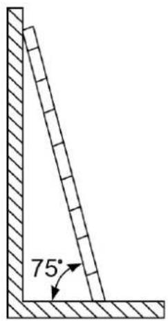
PI02SC0008
- When climbing a ladder, take the following precautions to reduce risks and ensure safety:
- Keep your body steady.
- Do not climb higher than the fourth rung of the ladder from the top.
- Ensure that your body's center of gravity does not shift outside the legs of the ladder.
Drilling Holes
When drilling holes into a wall or floor, observe the following safety precautions:
- Wear goggles and protective gloves when drilling holes.
- When drilling holes, protect the equipment from shavings. After drilling, clean up any shavings that have accumulated inside or outside the equipment.
Moving Heavy Objects
- Be cautious to avoid injury when moving heavy objects.
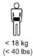
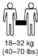

NH01H00144
- When moving the equipment by hand, wear protective gloves to prevent injuries.
1.6 Commissioning
When the equipment is powered on for the first time, ensure that professional personnel set parameters correctly. Incorrect settings may result in inconsistency with local certification and affect the normal operation of the equipment.
1.7 Maintenance and Replacement
! DANGER
High voltage generated by the equipment during operation may cause an electric shock, which could result in death, serious injury, or serious property damage. Prior to maintenance, power off the equipment and strictly comply with the safety precautions in this document and relevant documents.
- Maintain the equipment with sufficient knowledge of this document and using proper tools and testing equipment.
- Before maintaining the equipment, power it off and follow the instructions on the delayed discharge label to ensure that the equipment is powered off.
- Place temporary warning signs or erect fences to prevent unauthorized access to the maintenance site.
- If the equipment is faulty, contact your dealer.
- The equipment can be powered on only after all faults are rectified. Failing to do so may escalate faults or damage the equipment.
2 Product Introduction
2.1 Overview
Function
The SUN2000-(2KTL-5KTL)-L1 is a single-phase grid-tied string inverter that converts the DC power generated by PV strings into AC power and feeds the electricity into the power grid.
Model
This document involves the following product models:
- SUN2000-2KTL-L1
• SUN2000-3KTL-L1
• SUN2000-3.68KTL-L1
• SUN2000-4KTL-L1
• SUN2000-4.6KTL-L1
• SUN2000-5KTL-L1
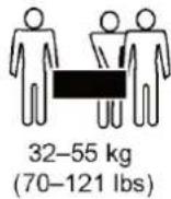
Figure 2-1 Model identifier (using SUN2000-5KTL-L1 as an example)
Table 2-1 Identifier description
| No. | Meaning | Value |
| 1 | Series name | SUN2000: grid-tied solar inverter |
| 2 | Power level | 2K: The power level is 2 kW.3K: The power level is 3 kW.3.68K: The power level is 3.68 kW.4K: The power level is 4 kW.4.6K: The power level is 4.6 kW.5K: The power level is 5 kW. |
| 3 | Topology | TL: transformerless |
| 4 | Design code | L1: residential |
Networking Application
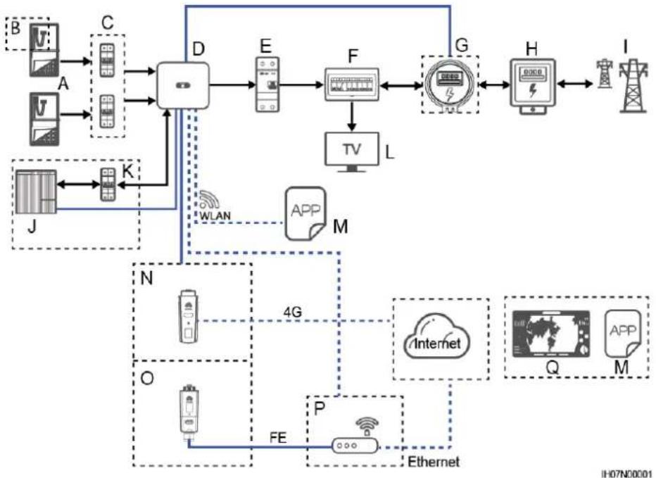
The SUN2000 applies to residential rooftop grid-tied systems. The system consists of PV strings, grid-tied solar inverters, AC switches, and power distribution units (PDUs).
Figure 2-2 Single SUN2000 scenario (dashed boxes indicate optional configuration)
flowchart
graph TD
    subgraph Device_1
        A["Device A"] --> C["Device C"]
        B["Device B"] --> C
        C --> D["Device D"]
        D --> E["Device E"]
        E --> F["Device F"]
        F --> G["Device G"]
        G --> H["Device H"]
        H --> I["Device I"]
    end

    subgraph Device_2
        J["Device J"] --> K["Device K"]
        K --> D
        D --> L["TV"]
        L --> M["App"]
        M --> N["4G"]
        N --> O["Internet"]
        O --> P["Ethernet"]
        P --> Q["Q"]
        Q --> R["APP"]
        R --> S["M"]
    end

    subgraph Device_3
        T["Device T"] --> U["Device U"]
        V["Device V"] --> U
        U --> W["Device W"]
        X["Device X"] --> Y["Device Y"]
        Z["Device Z"] --> Y
        Y --> AA["Device AA"]
        AB["Device AB"] --> AC["Device AC"]
        AD["Device AD"] --> AC
        AC --> AE["Device AE"]
        AF["Device AF"] --> AG["Device AG"]
        AH["Device AH"] --> AG
        AI["Device AI"] --> AJ["Device AJ"]
        AK["Device AK"] --> AJ
        AJ --> AL["Device AL"]
        AM["Device AM"] --> AN["Device AN"]
        AO["Device AO"] --> AN
        AP["Device AP"] --> AN
        AQ["Device AQ"] --> AN
        AR["Device AR"] --> AN
        AS["Device AS"] --> AN
        AT["Device AT"] --> AN
        AU["Device AU"] --> AN
        AV["Device AV"] --> AN
        AW["Device AW"] --> AN
        AX["Device AX"] --> AN
        AY["Device AY"] --> AZ["Device AZ"]
    end

    style Device_1 fill:#f9f,stroke:#333
    style Device_2 fill:#f9f,stroke:#333
    style Device_3 fill:#f9f,stroke:#333
    style Device_4 fill:#f9f,stroke:#333
    style Device_5 fill:#f9f,stroke:#333
    style Device_6 fill:#f9f,stroke:#333
    style Device_7 fill:#f9f,stroke:#333
    style Device_8 fill:#f9f,stroke:#333
    style Device_9 fill:#f9f,stroke:#333
    style Device_10 fill:#f9f,stroke:#333
    style Device_11 fill:#f9f,stroke:#333
    style Device_12 fill:#f9f,stroke:#333
    style Device_13 fill:#f9f,stroke:#333
    style Device_14 fill:#f9f,stroke:#333
    style Device_15 fill:#f9f,stroke:#333
    style Device_16 fill:#f9f,stroke:#333
    style Device_17 fill:#f9f,stroke:#333
    style Device_18 fill:#f9f,stroke:#333
    style Device_19 fill:#f9f,stroke:#333
    style Device_20 fill:#f9f,stroke:#333
    style Device_21 fill:#f9f,stroke:#333
    style Device_22 fill:#f9f,stroke:#333
    style Device_23 fill:#f9f,stroke:#333
    style Device_24 fill:#f9f,stroke:#333
    style Device_25 fill:#f9f,stroke:#333
    style Device_26 fill:#f9f,stroke:#333
    style Device_27 fill:#f9f,stroke:#333
    style Device_28 fill:#f9f,stroke:#333
    style Device_29 fill:#f9f,stroke:#333
    style Device_30 fill:#f9f,stroke:#333
    style Device_31 fill:#f9f,stroke:#333
    style Device_32 fill:#f9f,stroke:#333
    style Device_33 fill:#f9f,stroke:#333
    style Device_34 fill:#f9f,stroke:#333
    style Device_35 fill:#f9f,stroke:#333
    style Device_36 fill:#f9f,stroke:#333
    style Device_37 fill:#f9f,stroke:#333
    style Device_38 fill:#f9f,stroke:#333
    style Device_39 fill:#f9f,stroke:#333
    style Device_40 fill:#f9f,stroke:#333
    style Device_41 fill:#f9f,stroke:#333
    style Device_42 fill:#f9f,stroke:#333
    style Device_43 fill:#f9f,stroke:#333
    style Device_44 fill:#f9f,stroke:#333
    style Device_45 fill:#f9f,stroke:#333
    style Device_46 fill:#f9f,stroke:#333
    style Device_47 fill:#f9f,stroke:#333
    style Device_48 fill:#f9f,stroke:#333
    style Device_49 fill:#f9f,stroke:#333
    style Device_50 fill:#f9f,stroke:#333
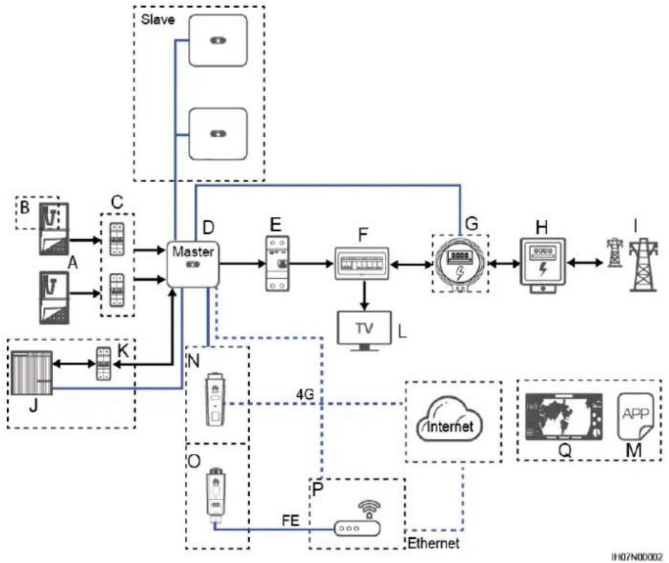
Figure 2-3 SUN2000 cascading scenario (dashed boxes indicate optional configuration)
flowchart
graph TD
    subgraph Master
        A["Slave"] --> D
        B["Slave"] --> D
        C["Slave"] --> D
        D --> E["Master"]
        E --> F["TV"]
        F --> G["Master"]
        G --> H["Internet"]
        H --> I["Tower"]
        J["Slave"] --> K["Master"]
        K --> L["Master"]
        L --> M["Master"]
        M --> N["Master"]
    end

    subgraph Internet
        O["Master"] --> P["FE"]
        P --> Q["Ethernet"]
        Q --> R["Master"]
        R --> S["Master"]
        S --> T["Master"]
        T --> U["Master"]
    end

    subgraph Ethernet
        V["Master"] --> W["Master"]
        X["Master"] --> Y["Master"]
        Z["Master"] --> AA["Master"]
        AB["Master"] --> AC["Master"]
    end

    Master --> D
    Master --> E
    Master --> F
    Master --> G
    Master --> H
    Master --> I
    Master --> J
    Master --> K
    Master --> L
    Master --> M
    Master --> N
    Master --> O
    Master --> P
    Master --> Q
    Master --> R
    Master --> S
    Master --> T
    Master --> U
    Master --> V
    Master --> X
    Master --> Y
    Master --> Z
    Master --> AB
    Master --> AC
    Master --> AD
    Master --> AE
    Master --> AF
    Master --> AG
    Master --> AH
    Master --> AI
    Master --> AJ
    Master --> AK
    Master --> AL
    Master --> AM
    Master --> AN
    Master --> AO
    Master --> AP
    Master --> AQ
    Master --> AR
    Master --> AS
    Master --> AT
    Master --> AU
    Master --> AV
    Master --> AW
    Master --> AX
    Master --> AY
    Master --> AZ
    Master --> BA
    Master --> BB
    Master --> BC
    Master --> BD
    Master --> BE
    Master --> BF
    Master --> BG
    Master --> BH
    Master --> BI
    Master --> BJ
    Master --> BK
    Master --> BL
    Master --> BM
    Master --> BN
    Master --> BO
    Master --> BP
    Master --> BQ
    Master --> BR
    Master --> BS
NOTE
- indicates the power flow direction, — indicates the signal line, and — indicates the wireless communication.
- In the SUN2000 cascading scenario, the master and slave solar inverters are both SUN2000-(2KTL-5KTL)-L1, and a maximum of three SUN2000s can be cascaded.
- In the SUN2000 cascading scenario, only one power meter (G in the figure) can be connected to the master inverter.
- In the SUN2000 cascading scenario, the SUN2000s connected to the power grid must meet the local power grid requirements.
(A) PV string
(B) Smart PV optimizer
(C) DC switch
(D) SUN2000
(E) AC switch
(F) Residential PDU
(G) Power meter
(H) Residential power meter
(I) Power grid
(J) Battery
(K) Battery switch
(L) Household load
(M) FusionSolar app
(N) 4G Smart Dongle
(O) WLAN-FE Smart Dongle
(P) Router
(Q) FusionSolar Smart PV Management System
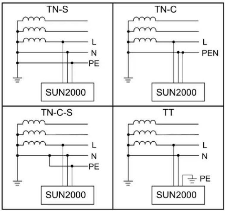
Supported Power Grid Types
The SUN2000 supports the following power grid types: TN-S, TN-C, TN-C-S, and TT. In the TT power grid, the N-to-PE voltage must be less than 30 V.
Figure 2-4 Power grid types
2.2 Component Description
Appearance
Figure 2-5 Appearance
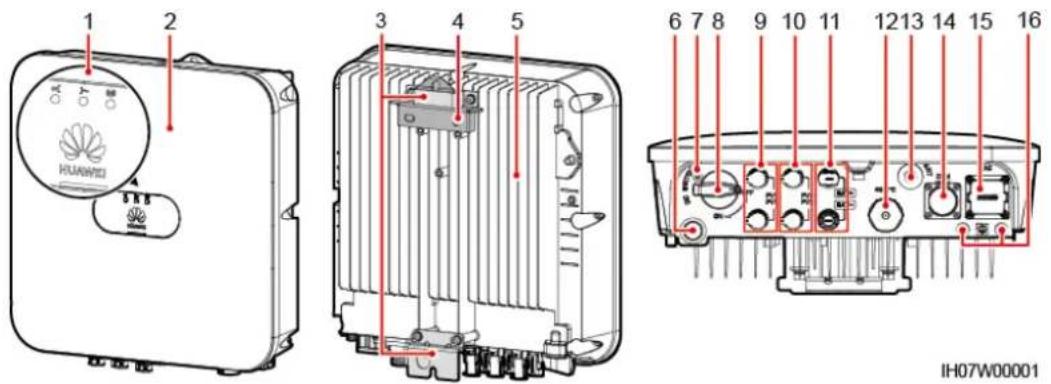
(1) LED indicators
(2) Front panel
(3) Hanging kit
(4) Mounting bracket
(5) Heat sink
(6) Ventilation valve
(7) DC switch locking screw hole ^4
(8) DC switch ^b (DC SWITCH)
(9) DC input terminals (PV1+/PV1−)
(10) DC input terminals (PV2+/PV2−)
(11) Battery terminals (BAT+/BAT−)
(12) Smart Dongle port (4G/FE)
(13) Antenna port (ANT)
(14) Communications port (COM)
(15) AC output port (AC)
(16) Ground point
NOTE
- Note a: The DC switch locking screw is used to lock the DC switch to prevent accidental startup. It is delivered with the SUN2000.
- Note b: DC input terminals PV1 and PV2 are controlled by the DC switch.
2.3 Label Description
Enclosure Labels
Table 2-2 Enclosure label description
| Icon | Name | Meaning | |
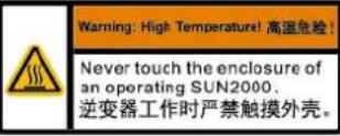 | Burn warning | Do not touch a running SUN2000 because the enclosure is hot when the SUN2000 is running. | |
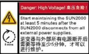 | Delayed discharge | High voltage exists after the SUN2000 is powered on. Only qualified and trained electrical technicians are allowed to perform operations on the SUN2000.Residual voltage exists after the SUN2000 is powered off. It takes 5 minutes for the SUN2000 to discharge to the safe voltage. | |
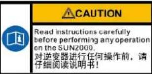 | Refer to documentation | Reminds operators to refer to the documents delivered the SUN2000. | |
 | Grounding | Indicates the position for connecting the protective earthing (PE) cable. | |
 | Do not disconnect under load!禁止带负荷断开连接! | Operation warning | Do not remove the connector or antenna when the SUN2000 is running. |
 | WARNINGHigh touch current, earth connection essential before connecting supply.大接触电流!接通电源前须先接地。 | Grounding warning | Ground the SUN2000 before powering it on. |
  | Serial number (SN) | Indicates the SUN2000 SN. | |
 | Media access control (MAC) address | Indicates the MAC address. | |
 | QR code for logging in to the SUN2000 WLAN | Scan the QR code to connect to the Huawei SUN2000 WLAN (Android) or obtain the WLAN login password (iOS). | |
NOTE
The labels are for reference only.
Nameplate
Figure 2-6 Nameplate (using SUN2000-5KTL-L1 as an example)
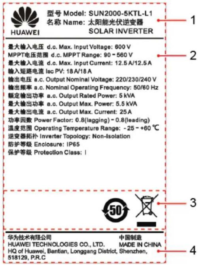
(1) Trademark and model
(2) Key technical specifications
(3) Compliance symbols
(4) Company name and country of origin
NOTE
The nameplate figure is for reference only.
2.4 Working Principles
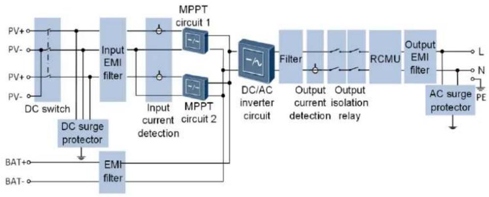
Schematic Diagram
The SUN2000 receives inputs from up to two PV strings. Then the inputs are grouped into two MPPT routes inside the SUN2000 to track the maximum power point of the PV strings. The DC power is then converted into single-phase AC power through an inverter circuit. Surge protection is supported on both the DC and AC sides.
The SUN2000 uses a reserved battery port for energy storage expansion. Battery performs charging and discharging operations according to the battery working mode.
Figure 2-7 Schematic diagram
flowchart
graph LR
    PV+ --> DCSwitch["DC switch"]
    PV- --> DCSwitch
    DCSwitch --> InputEMI1["Input EMI filter"]
    InputEMI1 --> MPPT1["MPPT circuit 1"]
    InputEMI1 --> MPPT2["MPPT circuit 2"]
    MPPT1 --> DCACinverter["DC/AC inverter circuit"]
    MPPT2 --> DCACinverter
    DCACinverter --> Filter1["Filter"]
    Filter1 --> OutputCurrent["Output current detection"]
    Filter1 --> OutputIsolation["Output isolation relay"]
    OutputCurrent --> RCMU["RCMU"]
    OutputIsolation --> RCMU
    RCMU --> OutputEMI2["Output EMI filter"]
    OutputEMI2 --> L["L"]
    OutputEMI2 --> N["N"]
    OutputEMI2 --> PE["PE"]
    BAT+ --> EMI3["EMI filter"]
    BAT- --> EMI3
    EMI3 --> DCSurgeProtection["DC surge protector"]
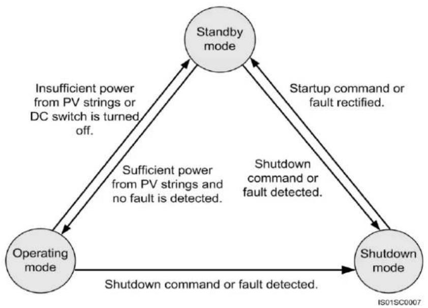
Working Mode
Figure 2-8 Working mode
flowchart
graph TD
    A["Standby mode"] -->|Startup command or fault rectified.| B["Shutdown mode"]
    B -->|Shutdown command or fault detected.| C["Operating mode"]
    C -->|Insufficient power from PV strings or DC switch is turned off.| A
    A -->|Sufficient power from PV strings and no fault is detected.| C
    B -->|Shutdown command or fault detected.| C
Table 2-3 Working mode description
| Working mode | Description |
| Standby mode | The SUN2000 enters Standby mode when the external environment does not meet the requirements for starting the SUN2000. In Standby mode:• The SUN2000 continuously detects its operation status. Once the operation conditions are met, the SUN2000 enters Operating mode.• If the SUN2000 detects a shutdown command or a fault after startup, it enters Shutdown mode. |
| Operating mode | In Operating mode:• The SUN2000 converts DC power from PV strings into AC power and feeds the power to the power grid.• The SUN2000 tracks the maximum power point to maximize the PV string output power.• If the SUN2000 detects a shutdown command or a fault, it enters Shutdown mode.• If the SUN2000 detects that the output power of PV strings does not meet the requirements for grid-tied power generation, it enters Standby mode. |
| Shutdown mode | • In Standby or Operating mode, if the SUN2000 detects a shutdown command or a fault, it enters Shutdown mode.• In Shutdown mode, if the SUN2000 detects that the fault is rectified or the startup command is executed, the SUN2000 enters Standby mode. |
3 SUN2000 Storage
The following requirements should be met if the SUN2000 is not put into use directly:
• Do not unpack the SUN2000.
- Keep the storage temperature at -40^ to +70^ and the humidity at 5% -95% RH.
- The product should be stored in a clean and dry place and be protected from dust and water vapor corrosion.
- A maximum of eight SUN2000s can be stacked. To avoid personal injury or device damage, stack SUN2000s with caution to prevent them from falling over.
- During the storage period, check the SUN2000 periodically. (It is recommended that the check is performed every three months.) Replace the packing materials that are damaged by insects or rodents in a timely manner.
- If the SUN2000 has been stored for more than two years, it must be checked and tested by professionals before being put into use.
4 System Installation
4.1 Checking Before the Installation
Checking Outer Packing
Before unpacking the SUN2000, check the outer packing for damage, such as holes and cracks, and check the SUN2000 model. If any damage is found or the SUN2000 model is not what you requested, do not unpack the package and contact your dealer as soon as possible.
NOTICE
You are advised to remove the packing materials within 24 hours before installing the SUN2000.
Checking Deliverables
After unpacking the SUN2000, check that the deliverables are intact and complete. If any item is missing or damaged, contact your dealer.
NOTE
For details about the number of accessories delivered with the SUN2000, see the Packing List in the packing case.
4.2 Preparing Tools and Instruments
| Type | Tools and Instruments | ||
| Installation | 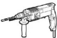 Hammer drill (with a drill bit of 8 mm) Hammer drill (with a drill bit of 8 mm) | 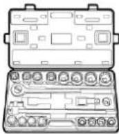 Torque socket wrench Torque socket wrench | 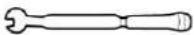 Torque wrench Torque wrench |
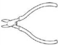 Diagonal pliers Diagonal pliers | 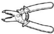 Wire strippers Wire strippers | 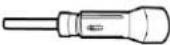 Torque screwdriver Torque screwdriver | |
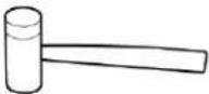 Rubber mallet Rubber mallet | 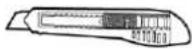 Utility knife Utility knife | 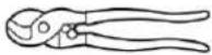 Cable cutter Cable cutter | |
 Crimping tool (model: PV-CZM-22100) Crimping tool (model: PV-CZM-22100) | 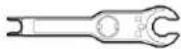 Disassembly and Assembly Tool (model: Staubli 13001462) Disassembly and Assembly Tool (model: Staubli 13001462) |  Cable tie Cable tie | |
 Vacuum cleaner Vacuum cleaner |  Multimeter (DC voltage measurement range ≥ 600 V DC) Multimeter (DC voltage measurement range ≥ 600 V DC) |  Marker Marker | |
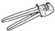
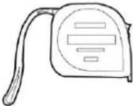 Steel measuring tape Steel measuring tape | 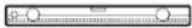 Level Level | 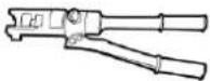 Hydraulic pliers Hydraulic pliers | |
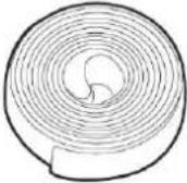 Heat-shrink tubing Heat-shrink tubing | 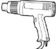 Heat gun Heat gun | - | |
| Personal protective equipment (PPE) |  Safety gloves Safety gloves | 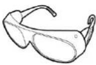 Safety goggles Safety goggles | 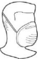 Anti-dust mask Anti-dust mask |
 Safety boots Safety boots | - | - | |
4.3 Determining the Installation Position
Basic Requirements
- The SUN2000 is protected to IP65 and can be installed indoors or outdoors.
- Do not install the SUN2000 in a place where personnel are easy to come into contact with its enclosure and heat sink, because these parts are extremely hot during operation.
- Do not install the SUN2000 near flammable or explosive materials.
- Do not install the SUN2000 at a place within children's reach.
- The SUN2000 will be corroded in salt areas, and the salt corrosion may cause fire. Do not install the SUN2000 outdoors in salt areas. A salt area refers to the region within 500 meters from the coast or prone to sea breeze. The regions prone to sea breeze vary with weather conditions (such as typhoons and monsoons) or terrains (such as dams and hills).
Installation Environment Requirements
- The SUN2000 must be installed in a well-ventilated environment to ensure good heat dissipation.
- When the SUN2000 is installed under direct sunlight, the power may be derated due to the temperature rise.
- You are advised to install the SUN2000 in a sheltered place or install an awning over it.
Mounting Structure Requirements
• The mounting structure where the SUN2000 is installed must be fire resistant.
- Do not install the SUN2000 on flammable building materials.
- Ensure that the installation surface is solid enough to bear the weight of the SUN2000.
- In residential areas, do not install the SUN2000 on plaster board walls or walls made of similar materials with a weak sound insulation performance because the noise generated by the SUN2000 may interfere with residents.
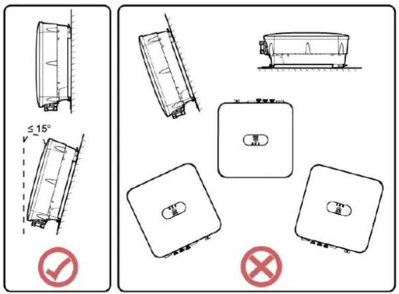
Installation Angle Requirements
The SUN2000 can be wall-mounted or pole-mounted. The installation angle requirements are as follows:
- Install the SUN2000 vertically or at a maximum back tilt of 15 degrees to facilitate heat dissipation.
- Do not install the SUN2000 at forward tilted, excessive back tilted, side tilted, horizontal, or upside down positions.
Figure 4-1 Installation angle
IH07H00004
Installation Space Requirements
- Reserve enough clearance around the SUN2000 to ensure sufficient space for installation and heat dissipation.
Figure 4-2 Installation space
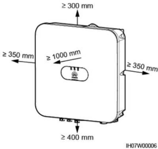
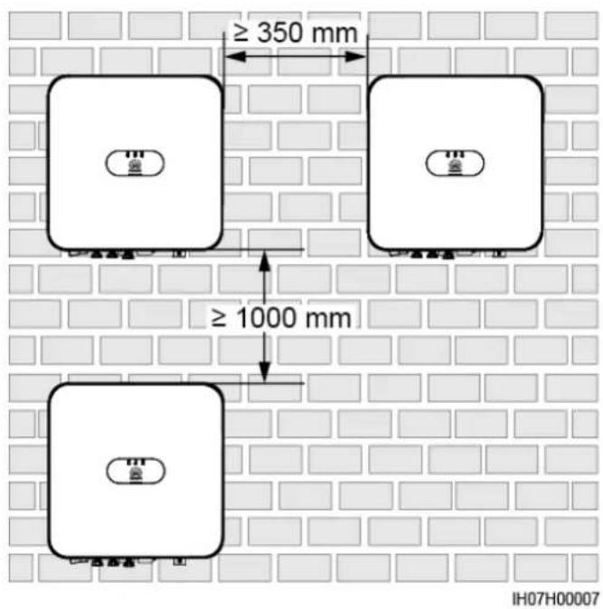
- When installing multiple SUN2000s, install them in horizontal mode if sufficient space is available and install them in triangle mode if no sufficient space is available. Stacked installation is not recommended.
Figure 4-3 Horizontal installation mode (recommended)
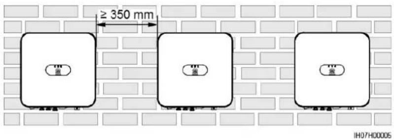
Figure 4-4 Triangle installation mode (recommended)
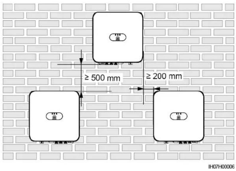
Figure 4-5 Stacked installation mode (not recommended)
NOTE
The installation figures are for reference only and are irrelevant to the SUN2000 cascading scenario.
4.4 Moving a SUN2000
Procedure
Step 1 Hold the handles on both sides of the SUN2000, lift the SUN2000 from the packing case, and transport it to the installation position.

CAUTION
- Move the SUN2000 with care to prevent device damage and personal injury.
- Do not use the wiring terminals and ports at the bottom to support any weight of the SUN2000.
- When you need to temporally place the SUN2000 on the ground, use foam, paper, or other protection material to prevent damage to its enclosure.
Figure 4-6 Moving a SUN2000
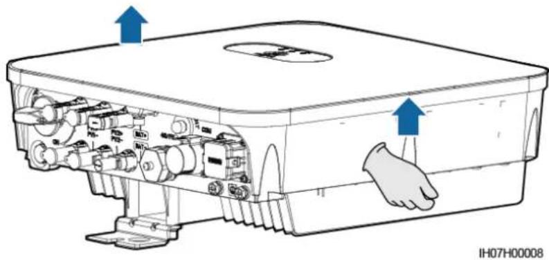
natural_image
Technical line drawing of a device with internal components and directional arrows indicating movement (no text or symbols)----End
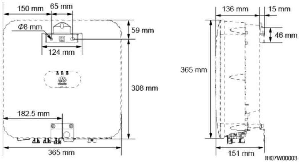
4.5 Installing a SUN2000
Installation Precautions
Figure 4-7 shows the dimensions of mounting holes for the SUN2000.
Figure 4-7 Mounting bracket dimensions
4.5.1 Wall-Mounted Installation
Procedure
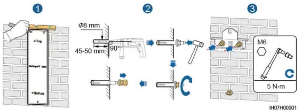
Step 1 Determine the positions for drilling holes using the marking-off template. Level the positions of mounting holes using a level, and mark the positions with a marker.
Step 2 Secure the mounting bracket.

DANGER
When drilling holes, avoid the water pipes and power cables buried in the wall.

NOTE
M6x60 expansion bolts are delivered with the SUN2000. If the length and amount of the bolts do not meet installation requirements, prepare M6 stainless steel expansion bolts by yourself.
Figure 4-8 Expansion bolt composition
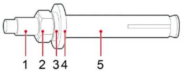
IS05W00018
(1) Bolt
(2) Nut
(3) Spring washer
(4) Flat washer
(5) Expansion sleeve
NOTICE
- To prevent dust inhalation or contact with eyes, wear safety goggles and an anti-dust mask when drilling holes.
- Wipe away any dust in or around the holes and measure the hole distances. If the holes are inaccurately positioned, drill holes again.
- Level the head of the expansion sleeve with the concrete wall after removing the nut, spring washer, and flat washer. Otherwise, the mounting bracket will not be securely installed on the wall.
- Loosen the nut, spring washer, and flat washer of the expansion bolt at the bottom.
Figure 4-9 Installing expansion bolts
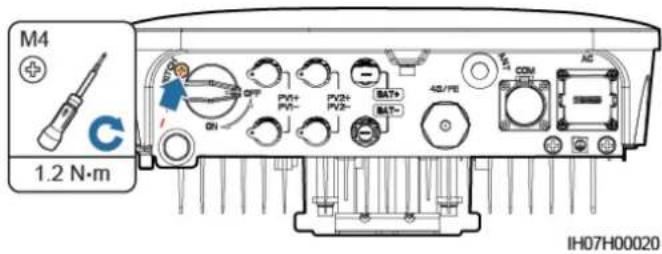
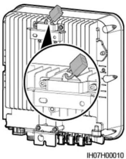
Step 3 (Optional) Install the locking screw for the DC switch.
Figure 4-10 Installing a locking screw for the DC switch
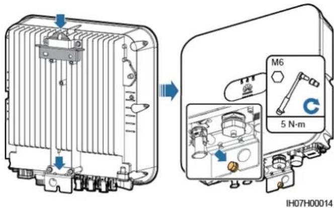
Step 4 Install the SUN2000 on the mounting bracket.
Step 5 Tighten the nuts.
Figure 4-11 Tightening nuts
Step 6 (Optional) Install an anti-theft lock.
NOTICE
- Prepare an anti-theft lock suitable for the lock hole diameter (Φ10 mm).
- An outdoor waterproof lock is recommended.
- Keep the key to the anti-theft lock.
Figure 4-12 Installing an anti-theft lock
natural_image
Technical diagram of an electrical component with a magnified inset showing internal structure (no text or symbols)----End
4.5.2 Support-Mounted Installation
Procedure
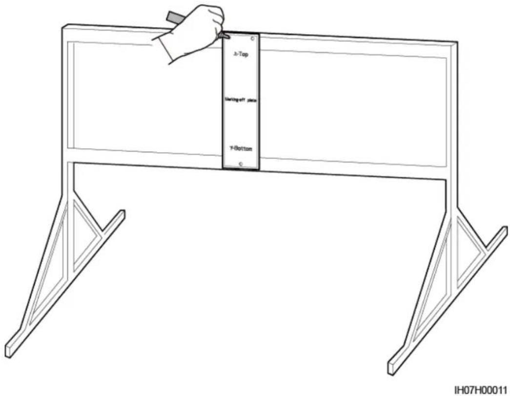
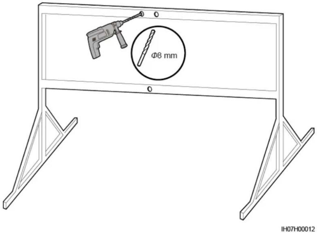
Step 1 Determine the positions for drilling holes using the marking-off template, and then mark the positions with a marker.
Figure 4-13 Determining hole positions
Step 2 Drill holes using a hammer drill.
NOTE
You are advised to apply anti-rust paint on the hole positions for protection.
Figure 4-14 Drilling holes
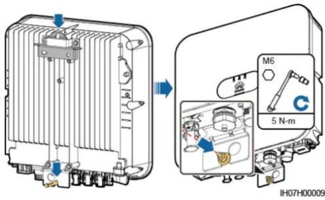
Step 3 Secure the mounting bracket.
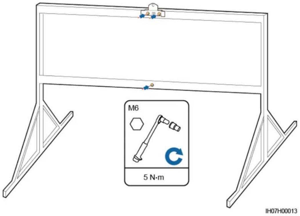
NOTE
Prepare bolt assemblies based on the hole diameter of the mounting bracket.
Step 4 (Optional) Install the locking screw for the DC switch.
Figure 4-15 Installing a locking screw for the DC switch
Step 5 Install the SUN2000 on the mounting bracket.
Step 6 Tighten the bolt assemblies.
Figure 4-16 Tightening bolt assemblies
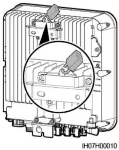
Step 7 (Optional) Install an anti-theft lock.
NOTICE
- Prepare an anti-theft lock suitable for the lock hole diameter (Φ10 mm).
- An outdoor waterproof lock is recommended.
- Keep the key to the anti-theft lock.
Figure 4-17 Installing an anti-theft lock
natural_image
Technical diagram of an electrical component with a magnified inset showing internal structure (no text or symbols)----End
5 Electrical Connection
5.1 Preparing Cables
Figure 5-1 SUN2000 cable connections (dashed boxes indicate optional configuration)
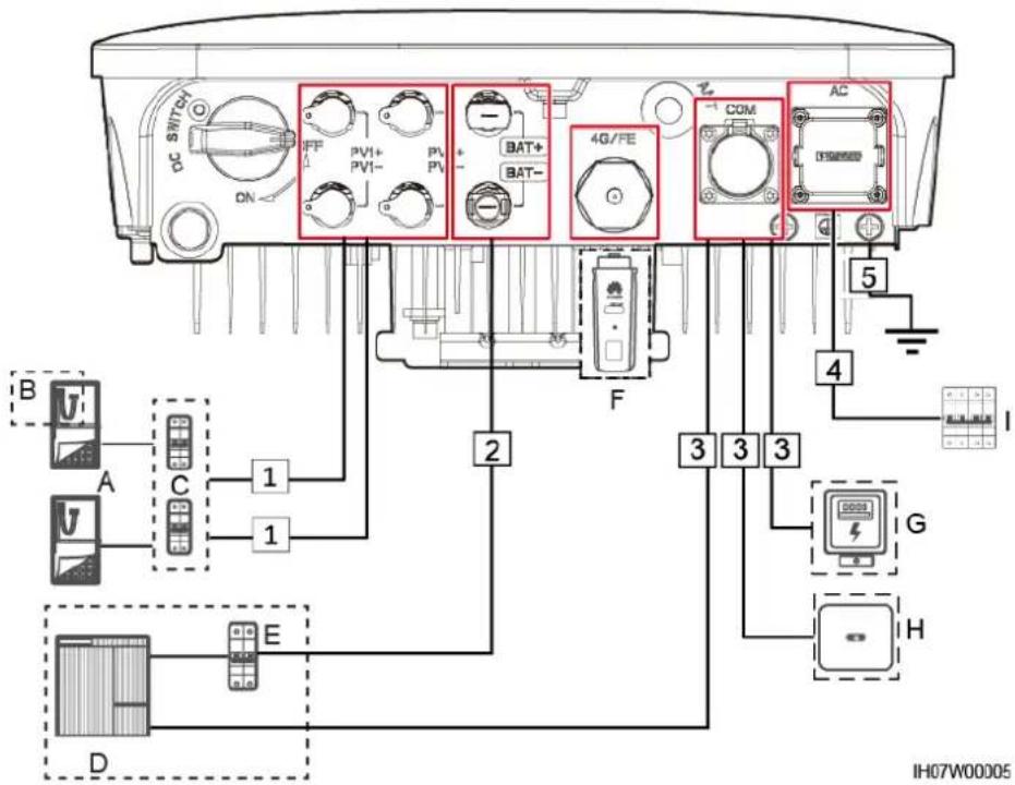
Table 5-1 Component description
| No. | Component | Description | Source |
| A | PV string | A PV string is composed of the PV modules connected in series and works with an optimizer.The SUN2000 supports the input from two PV strings. | Prepared by the customer |
| B | Smart PV optimizer | The SUN2000-450W-P smart PV optimizer is supported. | Purchased from Huawei |
| C | DC switch | Recommended: a DC circuit breaker with a rated voltage greater than or equal to 600 V DC and a rated current of 20 A | Prepared by the customer |
| D | Energy storage equipment | The SUN2000 can connect to LG-RESU batteries (LG RESU7H and RESU10H). | Prepared by the customer |
| E | Battery switch | Recommended: a DC circuit breaker with a rated voltage greater than or equal to 600 V DC and a rated current of 20 A | Prepared by the customer |
| F | Smart Dongle ^a | Supported models:WLAN-FE Smart Dongle: SDongleA-054G Smart Dongle: SDongleA-03 | Purchased from Huawei |
| G | Power meter ^b | The SUN2000 can connect to the DDSU666-H and DTSU666-H power meters. | Purchased from Huawei |
| The following third-party power meters are also supported:Gavazzi-EM340DINAV23X S1X08,Gavazzi-EM111DINAV81X S1X08,Gavazzi-EM112DINAV01X S1X08,CCS-WNC-3Y-400-MB, and CCS-WNC-3D-240-MB. | Prepared by the customer | ||
| H | SUN2000 | Select a proper model as required. | Purchased from Huawei |
| I | AC switch | Recommended: a single-phase AC circuit breaker with a rated voltage greater than or equal to 250 V AC and a rated current of:16 A(SUN2000-2KTL-L1)25 A(SUN2000-3KTL-L1 and SUN2000-3.68KTL-L1)32 A(SUN2000-4KTL-L1, SUN2000-4.6KTL-L1, and SUN2000-5KTL-L1) | Prepared by the customer |
| Note a: For details about how to use the 4G Smart Dongle SDongleA-03, see theSDongleA-03 Quick Guide (4G). For details about how to use the WLAN-FE Smart Dongle SDongleA-05, seeSDongleA-05 Quick Guide (WLAN-FE). You can obtain these documents athttps://support.huawei.com/enterpriseby searching for models.Note b: In Spain area, only the DDSU666-H power meter provided by Huawei can be used. | |||
Table 5-2 Cable description
| No. | Cable | Type | Recommended Specifications | Source |
| 1 | DC input power cable | Common outdoor PV cable in the industry (recommended model: PV1-F) | Conductor cross-sectional area: 4 mm^2 –6 mm^2 Cable outer diameter: 4.5 mm–7.8 mm | Prepared by the customer |
| 2 | (Optional ) Battery cable | Common outdoor PV cable in the industry (recommended model: PV1-F) | Conductor cross-sectional area: 4 mm^2 –6 mm^2 Cable outer diameter: 4.5 mm–7.8 mm | Prepared by the customer |
| 3 | (Optional) Signal cable | Outdoor shielded twisted pair cable | Conductor cross-sectional area: - Combined crimping of cables on the port: 0.20 mm^2 -0.35 mm^2 - Crimping the cables on the port without combining them: 0.20 mm^2 -1 mm^2 Cable outer diameter: - 4-hole rubber plug: 4-8 mm- 2-hole rubber plug: 8-11 mm | Prepared by the customer |
| 4 | AC output power cable^a | Not using the PE equipotential point at the AC output port: two-core (L and N) outdoor copper cableUsing the PE equipotential point at the AC output port: three-core (L, N, and PE) outdoor copper cable | Conductor cross-sectional area: 4 mm^2 -6 mm^2 Cable outer diameter: 10 mm-21 mm | Prepared by the customer |
| 5 | PE cable | Single-core outdoor copper cable and M6 OT terminal | 4 mm^2 -10 mm^2 | Prepared by the customer |
| Note a: The minimum cross-sectional area of the cable should be selected based on the rated value of the AC fuse. | ||||

NOTE
- The minimum cable diameter must comply with local cable standards.
- The factors that affect cable selection include the rated current, cable type, routing mode, ambient temperature, and maximum expected line loss.
5.2 Connecting PE Cables
Precautions
! DANGER
- Ensure that the PE cable is securely connected. Otherwise, electric shocks may occur.
- Do not connect the neutral wire to the enclosure as a PE cable. Otherwise, electric shocks may occur.
NOTE
- The PE point at the AC output port is used only as a PE equipotential point, and cannot substitute for the PE point on the enclosure.
- It is recommended that silica gel or paint be used around the ground terminal after the PE cable is connected.
Additional Information
The SUN2000 provides the grounding detection function. This function is used to check whether the SUN2000 is properly grounded before the SUN2000 starts, or check whether the ground cable is disconnected when the SUN2000 is running. This function is only available under limited conditions. To ensure the safe operation of the SUN2000, properly ground the SUN2000 according to the connection requirements of the ground cable. For some power grid types, if the output side of the SUN2000 is connected to an isolation transformer, ensure that the SUN2000 is properly grounded and set Grounding inspection to Disable to enable the SUN2000 to run properly. If you are not sure whether the SUN2000 is connected to such a type of power grid, contact your dealer or Huawei technical support for confirmation.
- According to IEC 62109, to ensure the safe operation of the SUN2000 in the case of ground cable damage or disconnection, properly connect the ground cable of the SUN2000 and ensure that it meets at least one of the following requirements before the grounding detection function becomes invalid:
The PE cable is a single-core outdoor copper cable with a conductor cross-sectional area of at least 10mm^2 .
- Use cables with the same diameter as the AC output power cable and ground the PE terminal on the AC connector and the ground screws on the chassis.
- In some countries and regions, the SUN2000 must have additional ground cables. Use cables with the same diameter as the AC output power cable and ground the PE terminal on the AC connector and the ground screws on the chassis.
Procedure
Step 1 Crimp an OT terminal.
NOTICE
- Avoid scratching the core wire when stripping a cable.
- The cavity formed after the conductor crimp strip of the OT terminal is crimped must wrap the core wires completely. The core wires must contact the OT terminal closely.
- Wrap the wire crimping area with heat shrink tubing or insulation tape. The heat shrink tubing is used as an example.
- When using a heat gun, protect the equipment from being scorched.
Figure 5-2 Crimping an OT terminal
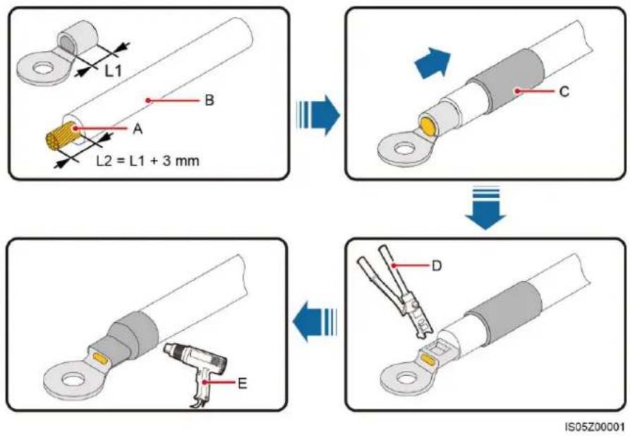
(A) Core wire
(B) Insulation layer
(C) Heat shrink tubing
(D) Hydraulic pliers
(E) Heat gun
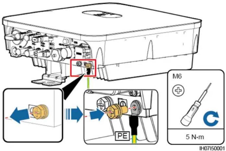
Step 2 Connect the PE cable.
NOTICE
- Ensure that the PE cable is connected securely.
- It is recommended to use the right ground point for grounding, and the other is a reserved ground point.
Figure 5-3 Connecting a PE cable
----End
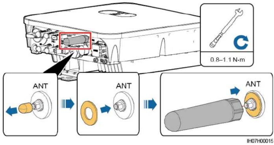
5.3 Installing a WLAN Antenna
Procedure
Step 1 Remove the watertight cap from the ANT port.
Step 2 Install the washer to the ANT port on the chassis.
Step 3 Install the WLAN antenna.
NOTICE
Ensure that the WLAN antenna is installed securely.
Figure 5-4 Installing a WLAN antenna
----End
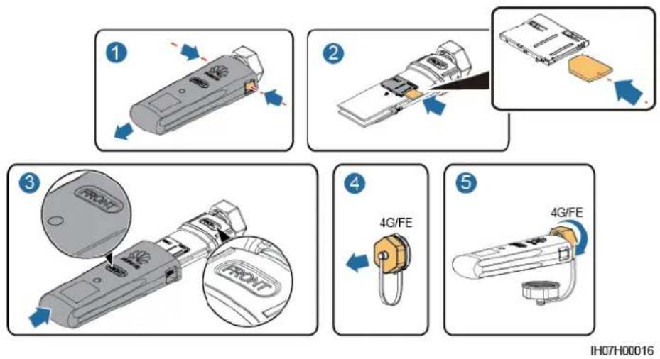
5.4 (Optional) Installing a Smart Dongle
Procedure
NOTE
- If you prepared a Smart Dongle without a SIM card, you need to prepare a standard SIM card (size: 25 mm x 15 mm) with the capacity greater than or equal to 64 KB.
- When installing the SIM card, determine its installation direction based on the silk screen and arrow on the card slot.
- Press the SIM card in place to lock it, indicating that the SIM card is correctly installed.
- When removing the SIM card, push it inwards to eject it.
- When reinstalling the cover of the Smart Dongle, ensure that the buckles spring back in place with a click sound.
• 4G Smart Dongle (4G Communication)
Figure 5-5 Installing a 4G Smart Dongle
• WLAN-FE Smart Dongle (FE Communication)
You are advised to use a CAT 5E outdoor shielded network cable (outer diameter < 9 mm; internal resistance ≤ 1.5 ohms/10 m) and shielded RJ45 connectors.
Figure 5-6 Installing a WLAN-FE Smart Dongle (FE communication)
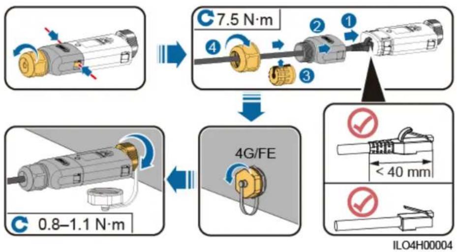
flowchart
graph TD
    A["Component 1: 7.5 N·m"] --> B["Component 2: 3"]
    B --> C["Component 3: 4"]
    C --> D["Component 4: 0.8–1.1 N·m"]
    D --> E["Component 5: <40 mm"]
    E --> F["Component 6: ILO4H00004"]
NOTE
There are two types of Smart Dongle:
- For details about how to use the WLAN-FE Smart Dongle SDongleA-05, see the SDongleA-05 Quick Guide (WLAN-FE). You can also scan the QR code to obtain the document.

- For details about how to use the 4G Smart Dongle SDongleA-03, see the SDongleA-03 Quick Guide (4G). You can also scan the QR code to obtain the document.

The quick guide is delivered with the Smart Dongle.
5.5 Connecting an AC Output Power Cable
Precautions
An AC switch must be installed on the AC side of the SUN2000 to ensure that the SUN2000 can be safely disconnected from the power grid.
Do not connect loads between the SUN2000 and the AC switch.
Procedure
Step 1 Connect the AC output power cable to the AC connector.
NOTICE
- The PE point at the AC output port is used only as a PE equipotential point, and cannot substitute for the PE point on the enclosure.
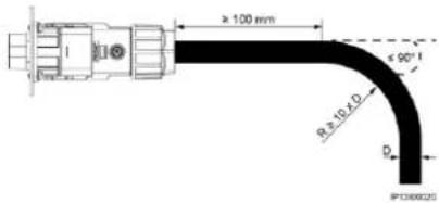
- Keep the AC output power cable and the PE cable close to each other.
- Keep the AC output power cable and the DC input power cable close to each other.
- Ensure that the cable jacket is inside the connector.
- Ensure that the exposed core is totally inserted into the cable hole.
- Ensure that AC output cable is secured. Failing to do so may cause SUN2000 malfunction or damage to its AC connector.
- Ensure that the cable is not twisted.
Figure 5-7 Assembling an AC connector (three-core wire)
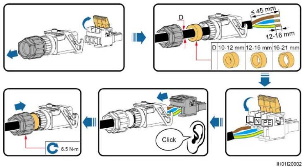
flowchart
graph TD
    A["Component 1: Cable with sensor input"] --> B["Component 2: Lens with 45 mm width and 12-16 mm thickness"]
    B --> C["Component 3: Cable with 6.5 N·m cable"]
    C --> D["Component 4: Lens with 10-12 mm width and 12-16 mm thickness"]
    D --> E["Component 5: Lens with 16-21 mm thickness"]
    E --> F["Final Display with L/N PE logo and 'Click' label"]
Figure 5-8 Assembling an AC connector (two-core wire)
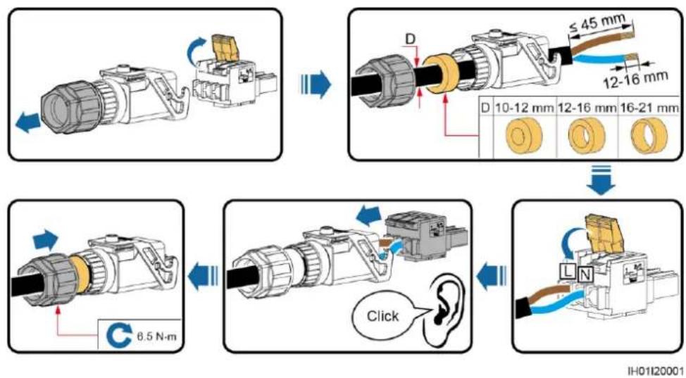
flowchart
graph TD
    A["Component 1: Lens with 6.5 N·m force"] --> B["Component 2: Lens with 12-16 mm diameter, 45 mm width, 12-16 mm length, and 10-12 mm thickness"]
    B --> C["Component 3: Lens with 16-21 mm diameter, 12-16 mm width, 10-12 mm thickness, and 12-16 mm length"]
    C --> D["Component 4: Lens with 8.5 N·m force, Click device, 8.5 N·m force"]
    D --> E["Component 5: Lens with 12-16 mm diameter, 45 mm width, 12-16 mm length, and 10-12 mm thickness"]
NOTE
- The cable colors shown in the figures are for reference only. Select an appropriate cable according to the local standards.
- For the core installation method and the length for cable stripping, see the instructions on the side of the plug insert.
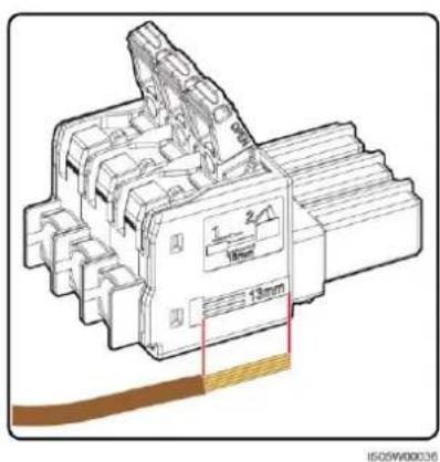
Figure 5-9 Length for cable stripping
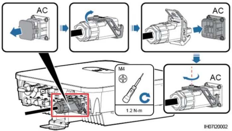
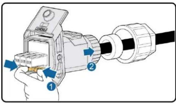
Step 2 Connect the AC connector to the AC output port.
NOTICE
Ensure that the AC connector is connected securely.
Figure 5-10 Securing an AC connector
Step 3 Check the route of the AC output power cable.
Figure 5-11 Cabling requirements
---End
Follow-up Procedure

WARNING
Before removing the AC connector, ensure that the DC switch at the bottom of the SUN2000 and all the switches connected to the SUN2000 are OFF.
To remove the AC connector from the SUN2000, perform the operations in reverse order.
Figure 5-12 Removing a plug insert
IS05H00031
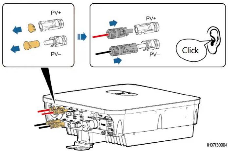
5.6 Connecting DC Input Power Cables
Precautions

DANGER
- Before connecting the DC input power cables, ensure that the DC voltage is within the safe range (lower than 60 V DC) and that the DC switch on the SUN2000 is OFF. Failing to do so may result in electric shocks.
- When the SUN2000 is running, it is not allowed to work on the DC input power cables, such as connecting or disconnecting a PV string or a PV module in a PV string. Failing to do so may cause electric shocks.
- If no PV string connects to a DC input terminal of the SUN2000, do not remove the watertight cap from the DC input terminals. Otherwise, the IP rating of the SUN2000 will be affected.

WARNING
Ensure that the following conditions are met. Otherwise, the SUN2000 may be damaged, or even a fire could happen.
- The DC input voltage of the SUN2000 shall not exceed maximum input voltage under any circumstance.
- The polarities of electric connections are correct on the DC input side. The positive and negative terminals of a PV string connect to corresponding positive and negative DC input terminals of the SUN2000.
- If the DC input power cables are reversely connected, do not operate the DC switch as well as positive and negative connectors immediately. Wait until the night when solar irradiance declines and the PV string current drops to below 0.5 A. Then set the DC switch to the OFF position, remove the positive and negative connectors, and correct the polarities of the DC input power cables.
NOTICE
- Since the output of the PV string connected to the SUN2000 cannot be grounded, ensure that the PV module output is well insulated to ground.
- During the installation of PV strings and the SUN2000, the positive or negative terminals of PV strings may be short-circuited to ground if the power cable is not properly installed or routed. In this case, an AC or DC short circuit may occur and damage the SUN2000. The caused device damage is not covered under any warranty or service agreement.
Figure 5-13 DC input terminals
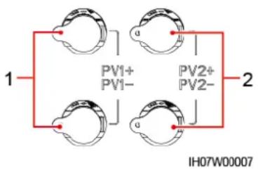
(1) Terminals of DC input 1
(2) Terminals of DC input 2
Procedure
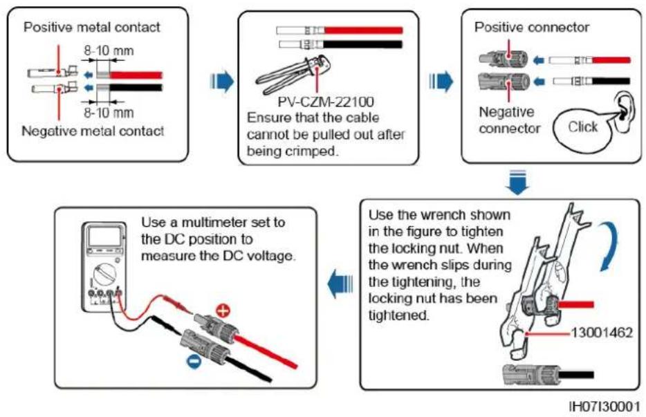
Step 1 Assemble a DC connector.

CAUTION
Use the Staubli MC4 positive and negative metal terminals and DC connectors delivered with the SUN2000. Using incompatible positive and negative metal terminals and DC connectors may result in serious consequences. The caused device damage is not covered under any warranty or service agreement.
NOTICE
- Keep the DC input PV+ cable and PV− cable close to each other.
- Cables with high rigidity, such as armored cables, are not recommended as DC input power cables, because poor contact may be caused by the bending of the cables.
- Before assembling DC connectors, label the cable polarities correctly to ensure correct cable connections.
- After crimping the positive and negative metal terminals, pull the DC input power cables back to ensure that they are connected securely.
- Insert the crimped metal terminals of the positive and negative power cables into the appropriate positive and negative connectors. Then pull back the DC input power cables to ensure that they are connected securely.
Figure 5-14 Assembling a DC connector
flowchart
graph TD
    A["Positive metal contact"] --> B["PV-CZM-22100"]
    B --> C["Use a multimeter set to the DC position to measure the DC voltage."]
    C --> D["Use the wrench shown in the figure to tighten the locking nut. When the wrench slips during the tightening, the locking nut has been tightened."]
    D --> E["Use the wrench shown in the figure to tighten the locking nut. When the wrench slips during the tightening, the locking nut has been tightened."]
NOTE
- If the PV string is not configured with an optimizer, use a multimeter to measure the voltage at the DC position. The multimeter must have a DC voltage range of at least 600 V. If the voltage is a negative value, the DC input polarity is incorrect and needs correction. If the voltage is greater than 600 V, too many PV modules are configured to the same string. Remove some PV modules.
- If the PV string is configured with an optimizer, check the cable polarity by referring to the Smart PV optimizer quick guide.
WARNING
Before performing Step 2, ensure that the DC switch is set to OFF.
Step 2 Insert the positive and negative connectors into corresponding DC input terminals on the SUN2000.
NOTICE
After the positive and negative connectors snap into place, pull the DC input power cables back to ensure that they are connected securely.
Figure 5-15 Connecting DC input power cables
NOTICE
If the DC input power cable is reversely connected and the DC switch is set to ON, do not immediately turn off the DC switch or reconnect the positive and negative connectors. Otherwise, the device may be damaged. The caused device damage is not covered under any warranty or service agreement. Wait until the night when solar irradiance declines and the PV string current drops to below 0.5 A. Then set the DC switch to the OFF position, remove the positive and negative connectors, and correct the polarities of the DC input power cables.
----End
Follow-up Procedure

WARNING
Before removing the positive and negative connectors, ensure that the DC switch is OFF.
To remove the positive and negative connectors from the SUN2000, insert a disassembly tool into the notch and press the tool with an appropriate force.
Figure 5-16 Removing a DC connector
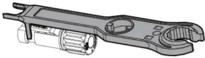
natural_image
Technical illustration of a mechanical wrench tool with internal gears and housing (no text or symbols)IH07H00019
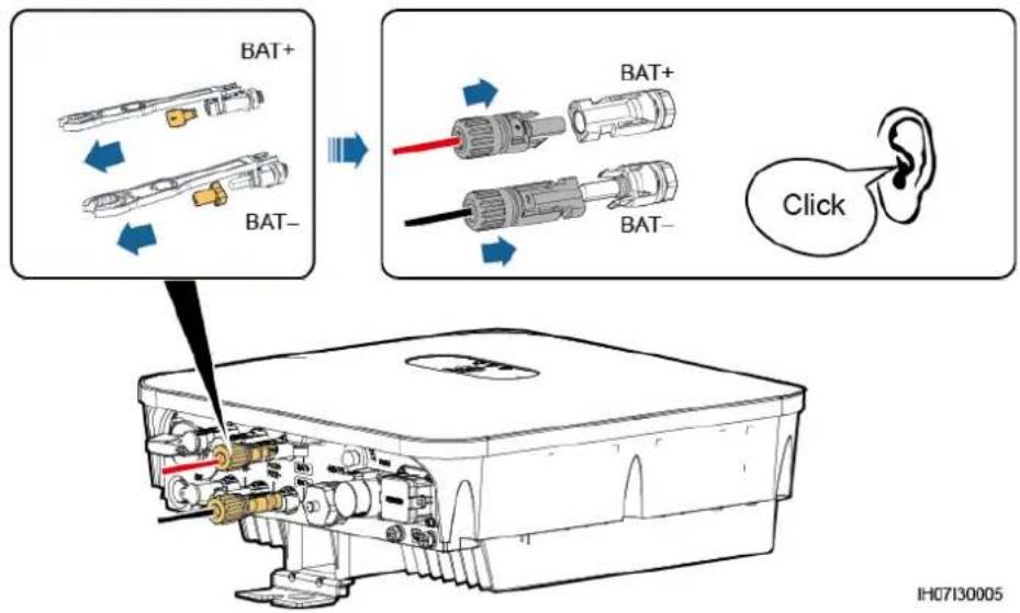
5.7 (Optional) Connecting Battery Cables
Prerequisites

DANGER
- Battery short circuits may cause personal injury. The high transient current generated by a short circuit may release a surge of power and cause fire.
- Do not connect or disconnect the battery cable when the SUN2000 is running. Failing to do so may cause electric shocks.
- Before connecting the battery cables, ensure that the DC switch on the SUN2000 and all the switches connecting to the SUN2000 are OFF, and the SUN2000 has no residual electricity. Otherwise, the high voltage of the SUN2000 and battery may result in electric shocks.
- If no battery connects to the SUN2000, do not remove the watertight cap from the battery terminal. Otherwise, the IP rating of the SUN2000 will be affected. If a battery connects to the SUN2000, set aside the watertight cap. Reinstall the watertight cap immediately after removing the connector. The high voltage of the battery terminal may result in electric shocks.
A battery switch can be configured between the SUN2000 and the battery to ensure that the SUN2000 can be safely disconnected from the battery.

WARNING
Do not connect loads between the SUN2000 and the battery.
The battery cables should be connected correctly. That is, the positive and negative terminals of the battery connect to the positive and negative battery terminals on the SUN2000 respectively. Otherwise, the SUN2000 may be damaged, or even a fire could happen.
NOTICE
- During the installation of the SUN2000 and battery, the positive or negative terminal of the battery will be short-circuited to ground if power cables are not installed or routed as required. In this case, an AC or DC short circuit may occur and damage the SUN2000. The caused device damage is not covered under any warranty or service agreement.
- The cabling distance between the battery and the SUN2000 should be less than or equal to 10 meters, and within 5 meters is recommended.
Procedure
Step 1 Assemble the positive and negative connectors by referring to 5.6 Connecting DC Input Power Cables.

DANGER
- The battery voltage will result in serious injury. Use dedicated insulation tools to connect cables.
- Ensure that cables are correctly connected between the battery terminal and the battery switch, and between the battery switch and the SUN2000 battery terminal.
NOTICE
Cables with high rigidity, such as armored cables, are not recommended as battery cables, because poor contact may be caused by the bending of the cables.
Step 2 Insert the positive and negative connectors into corresponding battery terminals on the SUN2000.
NOTICE
After the positive and negative connectors snap into place, pull the battery cables back to ensure that they are connected securely.
Figure 5-17 Connecting battery cables
----End
5.8 (Optional) Connecting Signal Cables
Context
NOTICE
When laying out signal cables, separate them from power cables and keep them away from strong interference sources to prevent communication interruption.
Figure 5-18 Signal cable ports
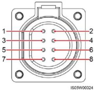
Table 5-3 COM port definition
| No. | Label | Definition | Single SUN2000 Scenario | SUN2000 Cascading Scenario |
| 1 | 485B1 | RS485B, RS485 differential signal- | - | Connects to the SUN2000s. |
| 2 | 485A1 | RS485A, RS485 differential signal+ | ||
| 3 | 485B2 | RS485B, RS485 differential signal- | Connects to a battery or power meter. | Connects to a battery or power meter. |
| 4 | 485A2 | RS485A, RS485 differential signal+ | ||
| 5 | GND | GND of the enable signal/12V/DI1/DI2 | Connects to the GND of the enable signal/12V/DI1/DI2 of a battery. | |
| 6 | EN+ | Enable signal+/12V+ | Connects to the enable signal of a battery and the positive terminal of 12V. | |
| 7 | DI1 | Digital input signal 1+ | Connects to the positive terminal of DI1. Connects to the DRM0 scheduling signal or serves as a reserved port for fast shutdown signals. | |
| 8 | DI2 | Digital input signal 2+ | Connects to the positive terminal of DI2 and serves as a reserved port for feedback signals of the grid-connected or off-grid controller. | |
NOTE
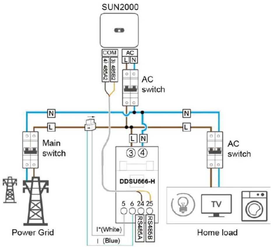
- When batteries and power meters coexist, they share the 485B2 and 485A2 ports.
- For details about how to connect signal cables, see the SUN2000L-(2KTL-5KTL) and SUN2000-(2KTL-5KTL)-L1 Battery and Smart Power Sensor Quick Guide. You can also scan the QR code to obtain the document.

Communication Networking Mode
NOTE
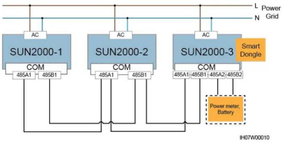
The power meter and Smart Dongle must be connected to the same SUN2000.
Figure 5-20 Connecting cables to the power meter (single SUN2000)
flowchart
graph TD
    A["SUN2000"] --> B["AC switch"]
    B --> C["Main switch"]
    C --> D["Power Grid"]
    B --> E["DC Switch"]
    E --> F["Home load"]
    subgraph Power Grid
        G["Power Tower"]
        H["AC Switch"]
    end
    I["DC Switch"] --> J["Main switch"]
    K["DC Switch"] --> L["Home Load"]
    M["DC Switch"] --> N["Home Load"]
    style A fill:#f9f,stroke:#333
    style B fill:#ccf,stroke:#333
    style C fill:#cfc,stroke:#333
    style D fill:#fcc,stroke:#333
    style E fill:#cff,stroke:#333
    style F fill:#ffc,stroke:#333
    style G fill:#fcc,stroke:#333
    style H fill:#fcc,stroke:#333
    style I fill:#fff,stroke:#333
    style J fill:#fff,stroke:#333
    style K fill:#fff,stroke:#333
    style L fill:#fff,stroke:#333
    style M fill:#fff,stroke:#333
    style N fill:#fff,stroke:#333
- In-phase grid connection
Figure 5-21 In-phase grid connection
flowchart
graph TD
    A["SUN2000-1"] -->|AC| B["COM"]
    C["SUN2000-2"] -->|AC| D["COM"]
    E["SUN2000-3"] -->|AC| F["COM"]
    B --> G["485A1 485B1"]
    D --> H["485A1 485B1"]
    F --> I["485A1 485B1 485A2 485B2"]
    J["Smart Dongle"] --> K["Power meter, Battery"]
    L["L Power Grid"] --> M["IH07W00010"]
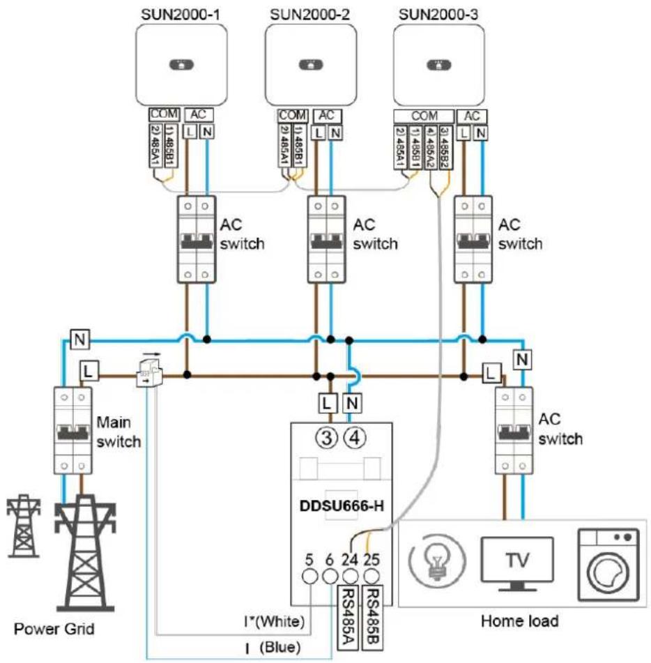
Figure 5-22 Connecting cables to the power meter (in-phase grid connection)
flowchart
graph TD
    subgraph Power Grid
        A["Power Grid"] --> B["Main switch"]
        B --> C["AC switch"]
        C --> D["DC"]
        D --> E["Home Load"]
    end

    subgraph SUN2000-1
        F["SUN2000-1"] --> G["COM 1:485A1"]
        H["SUN2000-1"] --> I["AC 1:485B1"]
        J["SUN2000-1"] --> K["COM 2:485A1"]
        L["SUN2000-1"] --> M["AC 2:485B1"]
        N["SUN2000-1"] --> O["COM 3:485A1"]
        P["SUN2000-1"] --> Q["AC 3:485A2"]
        R["SUN2000-1"] --> S["COM 4:485A2"]
        T["SUN2000-1"] --> U["AC 4:485B2"]
    end

    subgraph SUN2000-2
        V["SUN2000-2"] --> W["COM 1:485B1"]
        X["SUN2000-2"] --> Y["AC 1:485A1"]
        Z["SUN2000-2"] --> AA["COM 2:485A1"]
        AB["SUN2000-2"] --> AC["AC 2:485B2"]
        AD["SUN2000-2"] --> AE["COM 3:485A2"]
        AF["SUN2000-2"] --> AG["AC 3:485B2"]
    end

    subgraph SUN2000-3
        AH["SUN2000-3"] --> AI["COM 1:485B1"]
        AJ["SUN2000-3"] --> AK["AC 1:485A1"]
        AL["SUN2000-3"] --> AM["COM 2:485A1"]
        AN["SUN2000-3"] --> AO["AC 2:485B2"]
    end

    subgraph DDSU666-H
        AP["DDSU666-H"] --> AQ["DC ③④"]
        AR["DC"] --> AS["DC ③④"]
        AT["DC"] --> AU["DC ③④"]
    end

    subgraph Home Load
        AV["TV"] --> AW["Home Load"]
        AX["Power Grid"] --> AY["I*(White)"]
        AX --> AZ["I (Blue)"]
    end

    AY --> AA
    AZ --> AA
    style Power Grid fill:#f9f,stroke:#333
    style Home Load fill:#ccf,stroke:#333
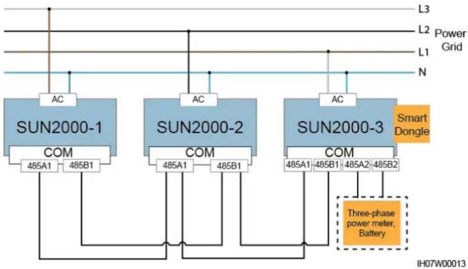
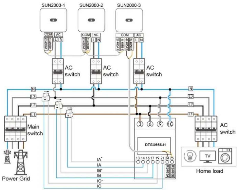
- Balanced three-phase grid connection
Figure 5-23 Balanced three-phase grid connection
flowchart
graph TD
    A["SUN2000-1"] --> B["AC"]
    C["SUN2000-2"] --> D["AC"]
    E["SUN2000-3"] --> F["AC"]
    B --> G["SUN2000-1 COM 485A1 485B1"]
    D --> H["SUN2000-2 COM 485A1 485B1"]
    F --> I["SUN2000-3 COM 485A1 485B1 485A2 485B2"]
    G --> J["Three-phase power meter, Battery"]
    H --> J
    I --> J
    J --> K["N"]
    L["L3"] --> A
    M["L2"] --> C
    N["L1"] --> E
    O["N"] --> E
    P["Power Grid"] --> A
    Q["Smart Dongle"] --> F
    R["IH07W00013"] --> J
Figure 5-24 Connecting cables to the power meter (balanced three-phase grid connection)
flowchart
graph TD
    A["Power Grid"] --> B["Main switch"]
    B --> C["AC switch"]
    C --> D["DTSU666-H"]
    D --> E["Home load"]
    E --> F["AC switch"]
    F --> G["Home load"]
    G --> H["Power Grid"]
    I["SUN2000-1"] --> J["COM 114581"]
    K["SUN2000-2"] --> L["COM 114581"]
    M["SUN2000-3"] --> N["COM 114581"]
    O["AC switch"] --> P["AC switch"]
    Q["AC switch"] --> R["AC switch"]
    S["AC switch"] --> T["AC switch"]
    U["AC switch"] --> V["AC switch"]
    W["AC switch"] --> X["AC switch"]
    Y["AC switch"] --> Z["AC switch"]
    AA["AC switch"] --> AB["AC switch"]
    AC["AC switch"] --> AD["AC switch"]
    AE["AC switch"] --> AF["AC switch"]
    AG["AC switch"] --> AH["AC switch"]
    AI["AC switch"] --> AJ["AC switch"]
    AK["AC switch"] --> AL["AC switch"]
    AM["AC switch"] --> AN["AC switch"]
    AO["AC switch"] --> AP["AC switch"]
    AQ["AC switch"] --> AR["AC switch"]
    AS["AC switch"] --> AT["AC switch"]
    AU["AC switch"] --> AV["AC switch"]
    AW["AC switch"] --> AX["AC switch"]
    AY["Power Grid"] --> AZ["L1"]
    AZ --> BA["L2"]
    BA --> BB["L3"]
    BB --> BC["L4"]
    BC --> BD["L5"]
    BD --> BE["L6"]
    BE --> BF["L7"]
    BF --> BG["L8"]
    BG --> BH["L9"]
    BH --> BI["L10"]
    BI --> BJ["L11"]
    BJ --> BK["L12"]
    BK --> BL["L13"]
    BL --> BM["L14"]
    BM --> BN["L15"]
    BN --> BO["L16"]
    BO --> BP["L17"]
    BP --> BQ["L18"]
    BQ --> BR["L19"]
    BR --> BS["L20"]
    BS --> BT["L21"]
    BT --> BU["L22"]
    BU --> BV["L23"]
    BV --> BW["L24"]
    BW --> BX["L25"]
    BX --> BY["RS485A"]
    BX --> BZ["RS485B"]
NOTE
- In the preceding networking, the SUN2000s are cascaded and support the grid-tied point control function to achieve zero export.
-
If the SUN2000s requires the grid-tied point control function, they need to be connected to a power meter.
-
In the scenario of balanced three-phase grid connection, if the SUN2000s requires the grid-tied point control function, they need to be connected to a three-phase power meter to control the total three-phase power.
- If there is only one battery, connect the battery to the master SUN2000. If there are multiple batteries, connect one battery to the master SUN2000 and the other batteries to the slave SUN2000s.
Procedure
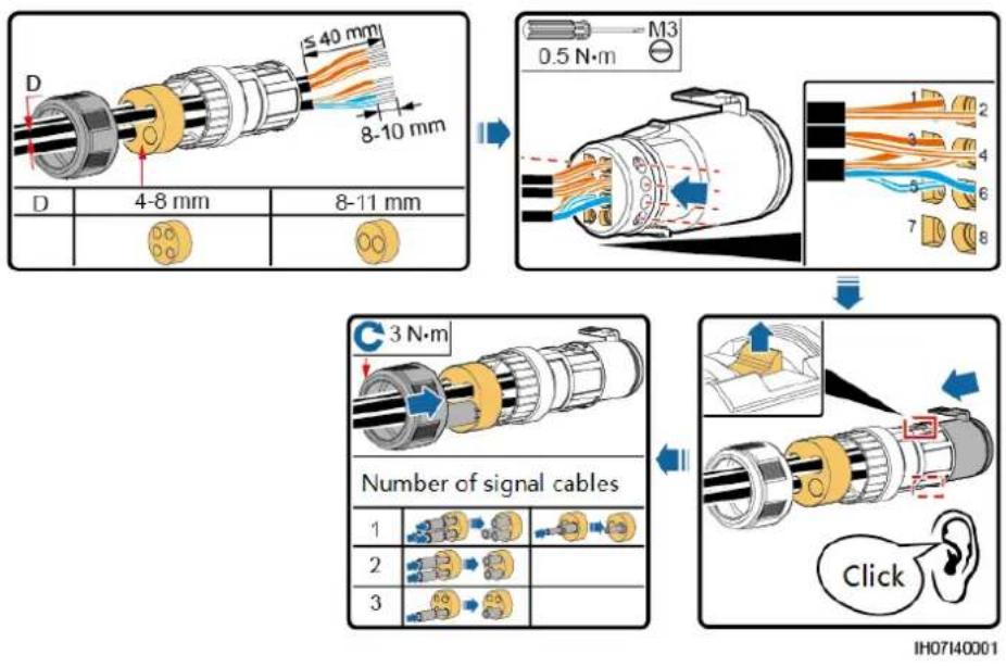
Step 1 Connect signal cables to corresponding signal connectors.
NOTICE
- Ensure that the protection layer of the cable is in the connector. The surplus core should be cut off from the protection layer.
- Ensure that the exposed core is totally inserted into the cable hole.
- Ensure that the signal cables are connected securely.
- Ensure that the cables are not twisted.
- If multiple signal cables need to be connected to a single connector, ensure that the outer diameters of the signal cables are the same.
Figure 5-25 Assembling a signal connector (single SUN2000)
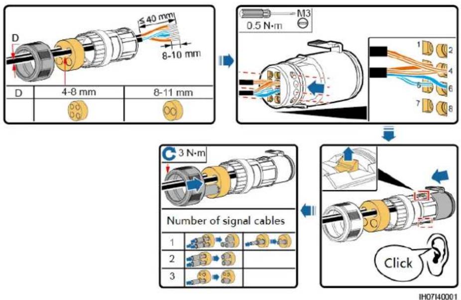
Figure 5-26 Assembling a signal connector (SUN2000 cascading)
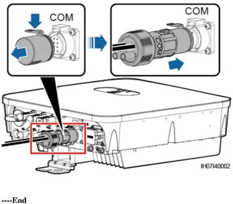
Step 2 Connect the signal connector to the corresponding port.
NOTICE
Ensure that the signal connector is connected securely.
Figure 5-27 Securing a signal connector
6 System Commissioning
6.1 Verification Before Power-On
Table 6-1 Check items and acceptance criteria
| No. | Check Item | Acceptance Criteria |
| 1 | SUN2000 | The SUN2000 is installed correctly and securely. |
| 2 | WLAN antenna | The WLAN antenna is installed correctly and securely. |
| 3 | Cables routing | Cables are routed properly as required by the customer. |
| 4 | Cable tie | Cable ties are evenly distributed and no burr exists. |
| 5 | Grounding | The PE cable is connected correctly, securely, and reliably. |
| 6 | Switch | The DC switch and all the switches connecting to the SUN2000 are OFF. |
| 7 | Cable connection | The AC output power cable, DC input power cable, battery cable, and signal cable are connected correctly, securely, and reliably. |
| 8 | Unused terminal and port | Unused terminals and ports are locked by watertight caps. |
| 9 | Installation environment | The installation space is proper, and the installation environment is clean and tidy. |
6.2 System Power-On
Prerequisites
Before turning on the AC switch between the SUN2000 and the power grid, use a multimeter to check that the AC voltage is within the allowed range.
NOTICE
- If the DC power supply is connected but the AC power supply is disconnected, the SUN2000 will report a Grid Loss alarm. The SUN2000 can start properly only after the power grid recovers.
- If the AC power supply is connected but the battery is not connected, the SUN2000 reports a Battery Abnormal alarm.
- If the SUN2000 is connected to batteries, turn on the DC switch within 1 minute after the AC switch is turned on. Otherwise, the SUN2000, connected to the power grid, will shut down and start again.
Procedure
Step 1 If the battery port of the SUN2000 is connected to a battery, turn on the auxiliary power switch of the battery and then the battery switch.
Step 2 Turn on the AC switch between the SUN2000 and the power grid.
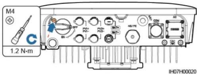
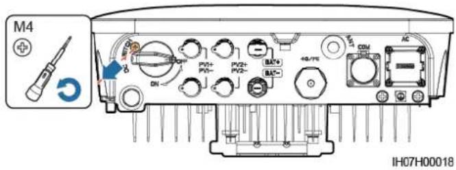
Step 3 (Optional) Remove the locking screw from the DC switch.
Figure 6-1 Removing the locking screw from a DC switch
Step 4 Turn on the DC switch between the PV string and the SUN2000 if there is any.
Step 5 Turn on the DC switch at the bottom of the SUN2000.
Step 6 Observe the LEDs to check the SUN2000 operating status.
Table 6-2 LED indicators 1
| Category | Status | Description | |
| Running indicator | LED1 | LED2 | - |
| [ ]~ [IMAGE] | Steady green | Steady green | The SUN2000 is operating in grid-tied mode. |
| Blinking green at long intervals (on for 1s and then off for 1s) | Off | The DC is on and the AC is off. | |
| Blinking green at long intervals (on for 1s and then off for 1s) | Blinking green at long intervals (on for 1s and then off for 1s) | Both the DC and AC are on, and the SUN2000 is not exporting power to the power grid. | |
| Off | Blinking green at long intervals (on for 1s and then off for 1s) | The DC is off and the AC is on. | |
| Off | Off | Both the DC and AC are off. | |
| Blinking red at short intervals (on for 0.2s and then off for 0.2s) | - | There is a DC environmental alarm, such as an alarm indicating that High String Input Voltage, String Reverse Connection, or Low Insulation Resistance. | |
| - | Blinking red at short intervals (on for 0.2s and then off for 0.2s) | There is an AC environmental alarm, such as an alarm indicating Grid Undervoltage, Grid Overvoltage, Grid Overfrequency, or Grid Underfrequency. | |
| Steady red | Steady red | Fault. | |
| Communication indicator[ ]~ [IMAGE] | LED3 | - | |
| Blinking green at short intervals (on for 0.2s and then off for 0.2s) | Communication is in progress. | ||
| Blinking green at long intervals (on for 1s and then off for 1s) | The mobile phone is connected to the SUN2000. | ||
| Off | There is no communication. | ||
Table 6-3 LED indicators 2
| Category | Status | Description | ||
| Device replacement indication | LED1 | LED2 | LED3 | - |
| Steady red | Steady red | Steady red | The SUN2000 hardware is faulty. The SUN2000 needs to be replaced. | |
----End
7 Man-Machine Interaction
7.1 App Commissioning
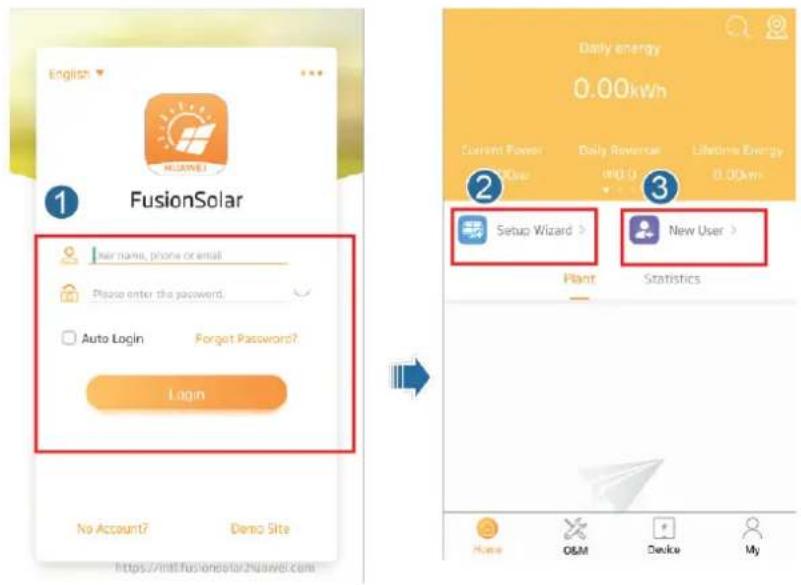
7.1.1 Downloading the FusionSolar App
Search for FusionSolar in Google Play (Android) to download and install the app. You can also scan one of the following QR codes to obtain the app.
Figure 7-1 QR code
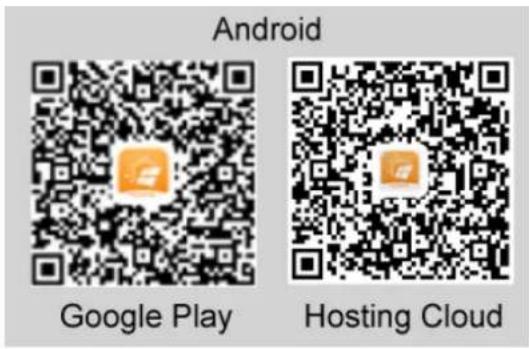
NOTE
- The latest Android version must be used for device commissioning. The iOS version is not updated and can be used only for viewing PV plant information. For iOS users, you can search for FusionSolar in the App Store or scan the following QR code to download the iOS version.

- The screenshots are for reference only. The actual screens prevail.
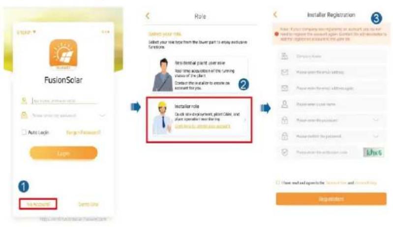
7.1.2 (Optional) Registering an Installer Account
NOTE
• If you have an installer account, skip this step.
• You can register an account only using a mobile phone only in China.
- The mobile number or email address used for registration is the user name for logging in to the FusionSolar app.
Create the first installer account and create a domain named after the company name.
Figure 7-2 Creating the first installer account
NOTICE
To create multiple installer accounts for a company, log in to the FusionSolar app and tap New User to create an installer account.
Figure 7-3 Creating multiple installer accounts for the same company
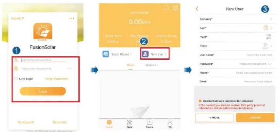
7.1.3 Creating a PV Plant and a User
Figure 7-4 Creating a PV plant and a user
NOTE
For details about how to use the site deployment wizard, see FusionSolar App Quick Guide. You can also scan the QR code to obtain the document.

7.1.4 (Optional) Setting the Physical Layout of the Smart PV Optimizers
NOTE
- If smart PV optimizers are configured for PV strings, ensure that the smart PV optimizers have been successfully connected to the SUN2000 before performing the operations in this section.
- Check that the SN labels of smart PV optimizers are correctly attached to the physical layout template.
- Take and save a photo of the physical layout template. Keep your phone parallel to the template and take a photo in landscape mode. Ensure that the four positioning points in the corners are in the frame. Ensure that each QR code is attached within the frame.
- For details about the physical layout of smart PV optimizers, see FusionSolar App Quick Guide. You can also scan the QR code to obtain the document.

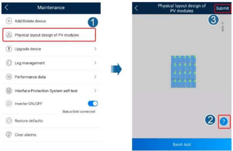
Step 1 Use the FusionSolar app to access the Device Commissioning screen to set the physical layout of smart PV optimizers.
-
Log in to the FusionSolar app. On the Device Commissioning screen, choose Maintenance > Physical layout design of PV modules.
-
After entering the Physical layout design of PV modules screen, perform operations as prompted. For details, see
-
Tap Submit after the operations are complete.
Figure 7-5 Physical layout design of PV modules
Step 2 Set the physical layout of smart PV optimizers on the WebUI of the FusionSolar Smart PV Management System (https://intl.fusionsolar.huawei.com).
- Log in to the FusionSolar app and tap the plant name on the home screen to access the plant screen. Tap Plant Layout, tap 🔍, upload the photo of the physical layout template as prompted, and tap Submit.
- Log in to https://intl.fusionsolar.huawei.com to access the WebUI of the FusionSolar smart PV management system.
- On the home page, click the plant name to go to the plant page. Select Plant Layout, click Add Physical Layout and then Generate with AI, create a physical layout diagram as prompted, and click OK.
NOTE
The physical layout of the optimizers in step 1 and step 2 must be the same.
----End
7.2 Parameters Settings
Go to the Device Commissioning screen and set SUN2000 parameters. For details about entering the Device Commissioning screen, see B Device Commissioning.
To set more parameters, tap Settings. For details about the parameters, see the FusionSolar APP and SUN2000 App User Manual. You can also scan the QR code to obtain the document.

7.2.1 Energy Control
On the home screen, tap Power adjustment to perform the corresponding operation.
Figure 7-6 Energy control
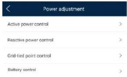
7.2.1.1 Grid-tied Point Control
Function
Limits or reduces the output power of the PV power system to ensure that the output power is within the power deviation limit.
Procedure
Step 1 On the home screen, choose Power adjustment > Grid-tied point control.
Figure 7-7 Grid-tied point control
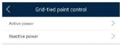
Table 7-1 Grid-tied point control
| Parameter Name | Description | ||
| Active power | Unlimited | - | If this parameter is set to Unlimited, the output power of the SUN2000 is not limited and the SUN2000 can connect to the power grid at the rated power. |
| Grid connection with zero power | Closed-loop controller | · If multiple SUN2000s are cascaded, set this parameter to SDongle/SmartLogger.· If there is only one SUN2000, set this parameter to Inverter. | |
| Limitation mode | Total power indicates export limitation of the total power at the grid-tied point. | ||
| Power adjustment period | Specifies the shortest interval for a single anti-backfeeding adjustment. | ||
| Power control hysteresis | Specifies the dead zone for adjusting the SUN2000 output power. If the power fluctuation is within the power control hysteresis, the power is not adjusted. | ||
| Active power output limit for fail-safe | Specifies the derating value of the SUN2000 active power by percentage. If the Smart Dongle does not detect any meter data or the communication between the Smart Dongle and the SUN2000 is disconnected, the Smart Dongle delivers the derating value of the SUN2000 active power by percentage. | ||
| Communication disconnection fail-safe | In the SUN2000 anti-backfeeding scenario, if this parameter is set to Enable, the SUN2000 will derate according to the active power derating percentage when the communication between the SUN2000 and the Smart Dongle is disconnected for a period longer than Communication disconnection detection time. | ||
| Communication disconnection detection time | Specifies the time for determining the communication disconnection between the SUN2000 and the Dongle.This parameter is displayed when Communication disconnection fail-safe is set to Enable. | ||
| Grid connection with limited power (kW) | Closed-loop controller | · If multiple SUN2000s are cascaded, set this parameter to SDongle/SmartLogger.· If there is only one SUN2000, set this parameter to Inverter. | |
| Limitation mode | Total power indicates export limitation of the total power at the grid-tied point. | ||
| Maximum grid feed-in power | Specifies the maximum active power transmitted from the grid-tied point to the power grid. | ||
| Power adjustment period | Specifies the shortest interval for a single anti-backfeeding adjustment. | ||
| Power control hysteresis | Specifies the dead zone for adjusting the SUN2000 output power. If the power fluctuation is within the power control hysteresis, the power is not adjusted. | ||
| Active power output limit for fail-safe | Specifies the derating value of the SUN2000 active power by percentage. If the Smart Dongle does not detect any meter data or the communication between the Smart Dongle and the SUN2000 is disconnected, the Smart Dongle delivers the derating value of the SUN2000 active power by percentage. | ||
| Communication disconnection fail-safe | In the SUN2000 anti-backfeeding scenario, if this parameter is set to Enable, the SUN2000 will derate according to the active power derating percentage when the communication between the SUN2000 and the Smart Dongle is disconnected for a period longer than Communication disconnection detection time. | ||
| Communication disconnection detection time | Specifies the time for determining the communication disconnection between the SUN2000 and the Dongle.This parameter is displayed when Communication disconnection fail-safe is set to Enable. | ||
| Grid connection with limited power (%) | Closed-loop controller | If multiple SUN2000s are cascaded, set this parameter to SDongle/SmartLogger.If there is only one SUN2000, set this parameter to Inverter. | |
| Limitation mode | Total power indicates export limitation of the total power at the grid-tied point. | ||
| PV plant capacity | Specifies the total maximum active power in the SUN2000 cascading scenario. | ||
| Maximum grid feed-in power | Specifies the percentage of the maximum active power of the grid-tied point to the PV plant capacity. | ||
| Power adjustment period | Specifies the shortest interval for a single anti-backfeeding adjustment. | ||
| Power control hysteresis | Specifies the dead zone for adjusting the SUN2000 output power. If the power fluctuation is within the power control hysteresis, the power is not adjusted. | ||
| Active power output limit for fail-safe | Specifies the derating value of the SUN2000 active power by percentage.If the Smart Dongle does not detect any meter data or the communication between the Smart Dongle and the SUN2000 is disconnected, the Smart Dongle delivers the derating value of the SUN2000 active power by percentage. | ||
| Communication disconnection fail-safe | In the SUN2000 anti-backfeeding scenario, if this parameter is set to Enable, the SUN2000 will derate according to the active power derating percentage when the communication between the SUN2000 and the Smart Dongle is disconnected for a period longer than Communication disconnection detection time. | ||
| Communication disconnection detection time | Specifies the time for determining the communication disconnection between the SUN2000 and the Dongle.This parameter is displayed when Communication disconnection fail-safe is set to Enable. | ||
----End
7.2.1.2 Battery Control
Function
If the SUN2000 connects to a battery, you need to set battery parameters.
Forcible Charge and Discharge
Step 1 On the home screen, choose Power adjustment > Battery control > Forced charge/discharge and perform operations as required. Tap Submit.
Figure 7-8 Forced charge/discharge
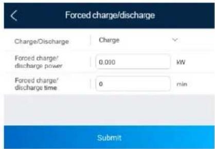
Table 7-2 Description of forced charge/discharge parameters
| Parameter | Description | Value Range |
| Charge/Discharge | Specifies the forced charge/discharge manually. | • Stop• Charge• Discharge |
| Forced charge/discharge power (kW) | Specifies the forced charge/discharge power. | Charge: [0, maximum charge power]Discharge: [0, maximum discharge power] |
| Forced charge/discharge time (min) | Specifies the forced charge/discharge duration. | [0, 1440] |
----End
Control Mode
Step 1 On the home screen, choose Power adjustment > Battery control > Control mode and perform the required operation. Tap Submit.
Figure 7-9 Fixed charge/discharge
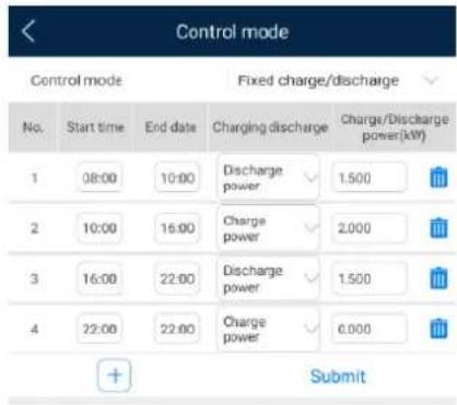
Figure 7-10 Maximum self-consumption
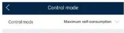
Figure 7-11 Time-of-use
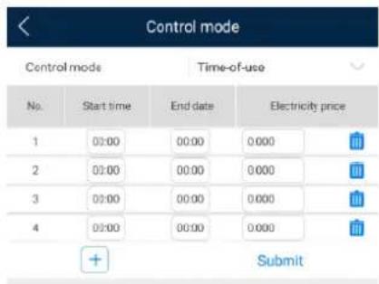
Table 7-3 Description of battery control parameters
| Parameter | Description | Value Range |
| Control mode | If this parameter is set to Fixed charge/discharge, the battery is charging or discharging during the configured period. A maximum of 10 time periods can be added.If this parameter is set to Maximum self-consumption and the SUN2000 is connected to a power meter, the SUN2000 provides output power for local loads before feeding the remaining power to the power grid.If this parameter is set to Time-of-use, the battery is discharged when the electricity price is high and charged when the electricity price is low. A maximum of 10 time periods can be added. | Fixed charge/dischargeMaximum self-consumptionTime-of-use |
----End
Feeding Power into Grid
Step 1 On the home screen, choose Power adjustment > Battery control > Charge from grid.
Figure 7-12 Charge from grid
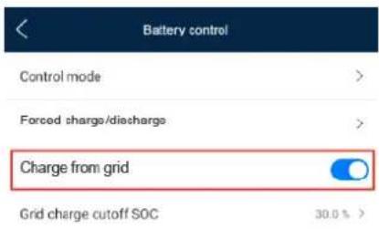
Table 7-4 Description of the grid charge parameter
| Parameter | Description | Value Range |
| Charge from grid | After Charge from grid is enabled, when the battery capacity is 2% lower than the discharge cutoff capacity, the system forcibly charges batteries from the power grid. The charging power is limited to 1 kW. When the battery capacity is higher than the Grid charge cutoff SOC, the system stops charging batteries from the power grid.To set the discharge cutoff capacity, choose Maintenance > Add/Delete device > Battery > End-of-discharge capacity on the home screen. The value range is 12%-20%, as shown in Figure 7-13.If Charge from grid function is disabled by default, comply with the grid charge requirements stipulated in local laws and regulations when this function is enabled. | DisableEnable |
Figure 7-13 End-of-discharge capacity
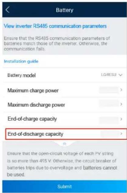
---End
7.2.2 AFCI
Function
If PV modules or cables are incorrectly connected or damaged, electric arcs may be generated, which may cause fire. Huawei solar inverters provide arc detection meets the requirement of UL 1699B-2018, ensuring the user safety and property.
This function is enabled by default. The solar inverter automatically detects arc faults. To disable this function, log in to the FusionSolar app, enter the Device Commissioning screen, choose Settings > Feature parameters, and disable AFCI.
For details about entering the Device Commissioning screen, see B Device Commissioning.
Clearing Alarms
The AFCI function involves the DC arc fault alarm.
The SUN2000 has the AFCI alarm automatic clearance mechanism. If an alarm is triggered for less than five times within 24 hours, the SUN2000 automatically clears the alarm. If the alarm is triggered for more than five times within 24 hours, the SUN2000 locks for protection. You need to manually clear the alarm on the SUN2000 so that it can work properly.
You can manually clear the alarm as follows:
Log in to the FusionSolar app and choose My > Device Commissioning. On the Device commissioning screen, connect and log in to the SUN2000 that generates the AFCI alarm, tap Alarm management, and tap Clear on the right of the DC arc fault alarm to clear the alarm.
Figure 7-14 Alarm management
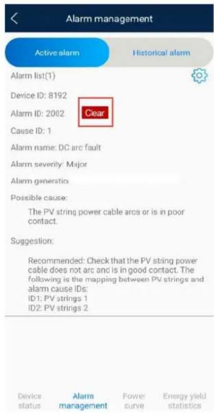
7.2.3 IPS Check (for Italy CEI0-21 Grid Code Only)
Function
The Italy CEI0-21 grid code requires an IPS check for the SUN2000. During the self-check, the SUN2000 checks the protection threshold and protection time of the maximum voltage over 10 min (59.S1), maximum overvoltage (59.S2), minimum undervoltage (27.S1), minimum undervoltage (27.S2), maximum overfrequency (81.S1), maximum overfrequency (81.S2), minimum underfrequency (81.S), and minimum underfrequency (81.S2).
Procedure
Step 1 On the home screen, choose Maintenance > IPS test to access the IPS test screen.
Step 2 Tap Start to start an IPS test. The SUN2000 detects maximum voltage over 10 min (59.S1), maximum overvoltage (59.S2), minimum undervoltage (27.S1), minimum undervoltage (27.S2), maximum overfrequency (81.S1), maximum overfrequency (81.S2), and minimum underfrequency (81.S1), and minimum underfrequency (81.S2).
Figure 7-15 IPS test
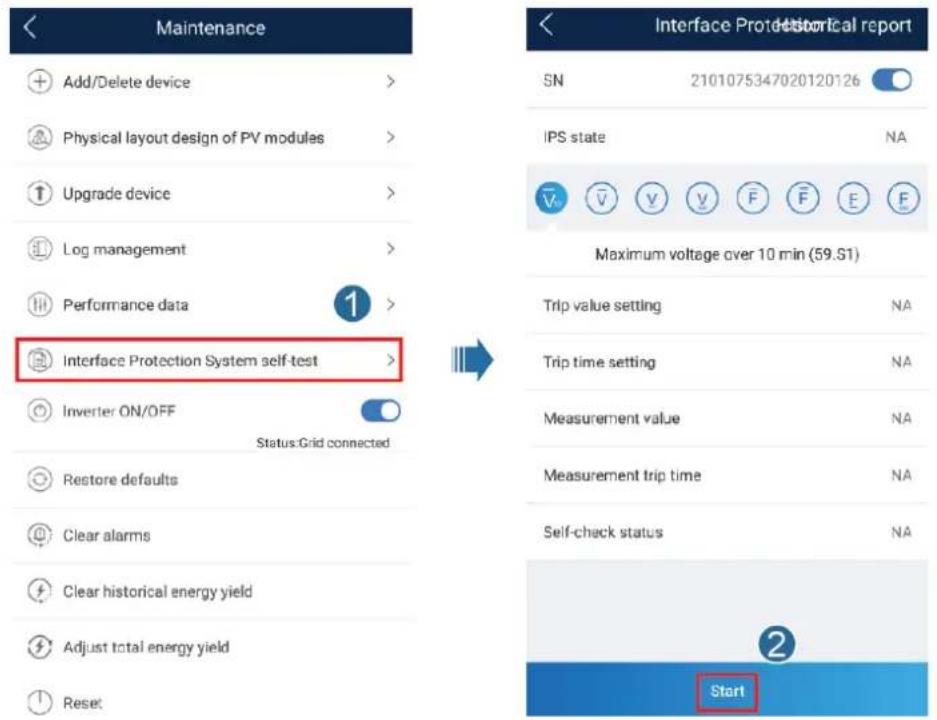
Table 7-5 IPS test type
| IPS Test Type | Description |
| Maximum voltage over 10 min (59.S1) | The default maximum voltage over 10 min protection threshold is 253 V (1.10 Vn), and the default protection time threshold is 3s. |
| Maximum overvoltage (59.S2) | The default overvoltage protection threshold is 264.5 V (1.15 Vn), and the default protection time threshold is 0.2s. |
| Minimum undervoltage (27.S1) | The default undervoltage protection threshold is 195.5 V (0.85 Vn), and the default protection time threshold is 1.5s. |
| Minimum undervoltage (27.S2) | The default undervoltage protection threshold is 34.5 V (0.15 Vn), and the default protection time threshold is 0.2s. |
| Maximum overfrequency (81.S1) | The default overfrequency protection threshold is 50.2 Hz, and the default protection time threshold is 0.1s. |
| Maximum overfrequency (81.S2) | The default overfrequency protection threshold is 51.5 Hz, and the default protection time threshold is 0.1s. |
| Minimum underfrequency (81.S1) | The default underfrequency protection threshold is 49.8 Hz, and the default protection time threshold is 0.1s. |
| Minimum underfrequency (81.S2) | The default underfrequency protection threshold is 47.5 Hz, and the default protection time threshold is 0.1s. |
Step 3 After the IPS test is complete, IPS State is displayed as IPS state success. Tap Historical report in the upper right corner of the screen to view the IPS check report.
----End
7.2.4 DRM (Australia AS4777)
Function
According to Australia AS 4777.2-2015, solar inverters need to support the function of demand response mode (DRM), and DRM0 is a mandatory requirement.
This function is disabled by default.
Figure 7-16 Wiring diagram for the DRM function
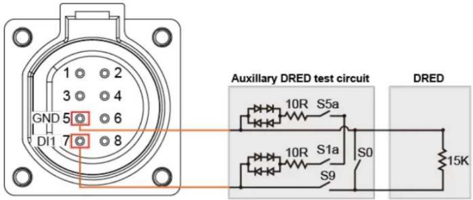
NOTE
The demand response enabling device (DRED) is a power grid dispatch device.
Table 7-6 DRM requirements
| Mode | Port on the SUN2000 | Requirements |
| DRM0 | DI1 and GND of the COM port | When switches S0 and S9 are switched on, the solar inverter should be turned off.When switch S0 is switched off, and switch S9 is switched on, the solar inverter should be grid-tied. |
Procedure
Step 1 On the home page, choose Settings > Feature parameters.
Step 2 Set DRM to

Figure 7-17 DRM
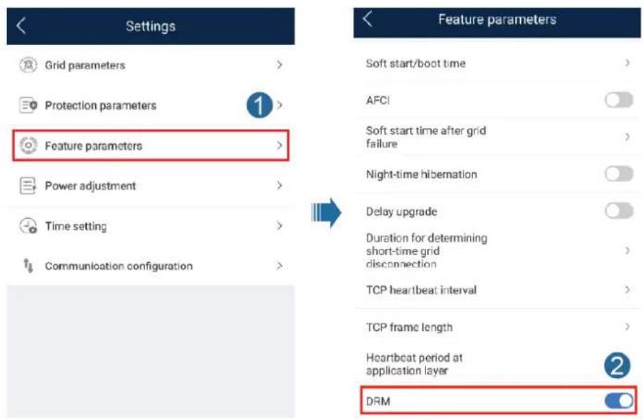
----End
8 System Maintenance
8.1 System Power-Off
Precautions
After the SUN2000 powers off, the remaining electricity and heat may still cause electric shocks and body burns. Therefore, put on protective gloves and begin operating the SUN2000 five minutes after the power-off.
Procedure
Step 1 Send a shutdown command on the app.
Step 2 Turn off the AC switch between the SUN2000 and the power grid.
Step 3 Turn off the DC switch at the bottom of the SUN2000.
Step 4 (Optional) Install the locking screw for the DC switch.
Figure 8-1 Installing a locking screw for the DC switch

Step 5 Turn off the DC switch between the SUN2000 and PV strings.
Step 6 (Optional) Turn off the battery switch between the SUN2000 and batteries.
----End
8.2 Routine Maintenance
To ensure that the SUN2000 can operate properly for a long term, you are advised to perform routine maintenance on it as described in this chapter.

CAUTION
Before cleaning the SUN2000, connecting cables, and maintaining the grounding reliability, power off the SUN2000 (see 8.1 System Power-Off for details).
Table 8-1 Maintenance checklist
| Check Item | Check Method | Maintenance Interval |
| System cleanliness | Check periodically that the heat sinks are free from obstacles and dust. | Once every 6 to 12 months |
| System running status | Check that the SUN2000 is not damaged or deformed.Check that the SUN2000 operates with no abnormal sound.Check that all SUN2000 parameters are correctly set during operation. | Once every six months |
| Electrical connection | Check that cables are secured.Check that cables are intact, and that in particular, the parts touching the metallic surface are not scratched.Check that unused DC input terminals, battery terminals, COM ports, ANT ports, and Smart Dongle waterproof covers are locked. | The first inspection is 6 months after the initial commissioning. From then on, the interval can be 6 to 12 months. |
| Grounding reliability | Check that ground cables are securely connected. | The first inspection is 6 months after the initial commissioning. From then on, the interval can be 6 to 12 months. |
8.3 Troubleshooting
Alarm severities are defined as follows:
- Major: The SUN2000 enters the shutdown mode and disconnects from the power grid to stop generating power after a fault occurs.
- Minor: Some components are faulty but the SUN2000 can still connect to the power grid and generate power.
- Warning: The SUN2000 functions normally, but its output power decreases due to external factors.
Table 8-2 Common alarms and troubleshooting measures
| Alarm ID | Alarm Name | Alarm Severity | Possible Causes | Troubleshooting |
| 2001 | High String Input Voltage | Major | The PV array is not properly configured. Excessive PV modules are connected in series to the PV string, and therefore the open-circuit voltage exceeds the maximum SUN2000 operating voltage.Cause ID = 1, 21: The PV1 input voltage is high.2: The PV2 input voltage is high. | Check the serial connection configuration of the PV string and ensure that the PV string open-circuit voltage is not greater than the maximum operating voltage of the SUN2000. After the PV array configuration is corrected, the alarm disappears. |
| 2002 | DC Arc Fault | Major | The PV string power cables arc or are in poor contact.Cause ID = 1, 21: PV1 DC arc fault2: PV2 DC arc fault | Check whether the string cables arc or are in poor contact. |
| 2011 | String Reversed | Major | The PV string is reversely connected.Cause ID = 1, 21: PV1 is reversely connected.2: PV2 is reversely connected. | Check whether the PV string is reversely connected to the SUN2000. If yes, wait until the PV string current decreases below 0.5 A, set DC switch to OFF, and adjust the PV string polarity. |
| 2021 | AFCI Check Failure | Major | The AFCI check fails.Cause ID = 1, 21: The AFCI check circuit is abnormal.2: The AFCI circuit is faulty. | Turn off the AC output switch and DC input switch, and then turn them on after 5 minutes. If the fault persists, contact your dealer or Huawei technical support. |
| 2032 | Grid Failure | Major | Cause ID = 1The power grid experiences an outage.The AC circuit is disconnected or the AC circuit breaker is OFF. | 1. Check the AC voltage.2. Check whether the AC circuit is disconnected or the AC circuit breaker is OFF. |
| 2033 | Grid Undervoltage | Major | Cause ID = 1The grid voltage is below the lower threshold or the low voltage duration has lasted for more than the value specified by low voltage ride-through (LVRT). | 1. If the alarm occurs occasionally, the power grid may be abnormal temporarily. The SUN2000 automatically recovers after detecting that the power grid becomes normal.2. If the alarm occurs frequently, check whether the power grid voltage is within the allowed range. If no, contact the local power operator. If yes, modify the grid undervoltage protection threshold through the mobile app, SmartLogger, or network management system (NMS) with the consent of the local power operator.3. If the fault persists for a long time, check the connection between the AC switch and the output power cable. |
| 2034 | Grid Overvoltage | Major | Cause ID = 1The grid voltage exceeds the higher threshold or the high voltage has lasted for more than the value specified by high voltage ride-through (HVRT). | 1. If the alarm occurs occasionally, the power grid may be abnormal temporarily. The SUN2000 automatically recovers after detecting that the power grid becomes normal.2. If the alarm occurs frequently, check whether the power grid voltage is within the allowed range. If no, contact the local power operator. If yes, modify the grid overvoltage protection threshold through the mobile app, SmartLogger, or NMS with the consent of the local power operator.3. Check whether the peak voltage of the power grid is too high. If the fault persists and cannot be rectified for a long time, contact the power operator. |
| 2036 | Grid Overfrequency | Major | Cause ID = 1Power grid exception: The actual power grid frequency is higher than the standard requirement for the local power grid. | 1. If the alarm occurs occasionally, the power grid may be abnormal temporarily. The SUN2000 automatically recovers after detecting that the power grid becomes normal.2. If the alarm occurs frequently, check whether the power grid frequency is within the allowed range. If no, contact the local power operator. If yes, modify the grid overfrequency protection threshold through the mobile app, SmartLogger, or NMS with the consent of the local power operator. |
| 2037 | Grid Underfrequency | Major | Cause ID = 1Power grid exception: The actual power grid frequency is lower than the standard requirement for the local power grid. | 1. If the alarm occurs occasionally, the power grid may be abnormal temporarily. The SUN2000 automatically recovers after detecting that the power grid becomes normal.2. If the alarm occurs frequently, check whether the power grid frequency is within the allowed range. If no, contact the local power operator. If yes, modify the grid underfrequency protection threshold through the mobile app, SmartLogger, or NMS with the consent of the local power operator. |
| 2038 | Unstable Grid Frequency | Major | Cause ID = 1Power grid exception: The actual grid frequency change rate does not comply with the local power grid standard. | 1. If the alarm occurs occasionally, the power grid may be abnormal temporarily. The SUN2000 automatically recovers after detecting that the power grid becomes normal.2. If the alarm occurs frequently, check whether the power grid frequency is within the allowed range. If no, contact the local power operator. |
| 2039 | Output Overcurrent | Major | Cause ID = 1The power grid voltage drops dramatically or the power grid is short-circuited. As a result, the SUN2000 transient output current exceeds the upper threshold and therefore the SUN2000 protection is triggered. | 1. The SUN2000 detects its external working conditions in real time. After the fault is rectified, the SUN2000 automatically recovers.2. If the alarm occurs frequently and affects the energy yield of the power plant, check whether the output is short-circuited. If the fault persists, contact your dealer or Huawei technical support. |
| 2040 | Output DC Component Overhigh | Major | Cause ID = 1The DC component of the SUN2000 output current exceeds the specified upper threshold. | 1. The SUN2000 detects its external working conditions in real time. After the fault is rectified, the SUN2000 automatically recovers.2. If the alarm occurs frequently, contact your dealer or Huawei technical support. |
| 2051 | Abnormal Residual Current | Major | Cause ID = 1The insulation impedance of the input side to PE decreases when the SUN2000 is operating. | 1. If the alarm occurs occasionally, the external circuit may be abnormal temporarily. The SUN2000 automatically recovers after the fault is rectified.2. If the alarm occurs frequently or persists, check whether the impedance between the PV string and the ground is too low. |
| 2062 | Low Insulation Resistance | Major | Cause ID = 1A short circuit occurs between the PV array and the ground.The ambient air of the PV array is damp and the insulation between the PV array and the ground is poor. | 1. Check the output impedance of the PV array to ground. If there is a short circuit or lack of insulation, rectify it.2. Check that the PE cable of the SUN2000 is correctly connected.3. If the impedance is lower than the specified protection threshold in rainy and cloudy days, setInsulation resistance protection using the mobile app, SmartLogger, or NMS.Current insulation resistance: x MΩ, possible short circuit position: x%. The short circuit position is valid for a single PV string. If there are multiple PV strings, check the PV strings one by one. For details, seeELocating Insulation Resistance Faults. |
| 2063 | Overtemperature | Minor | Cause ID = 1The SUN2000 is installed in a place with poor ventilation.The ambient temperature is higher than the upper threshold.The SUN2000 is not working properly. | Check the ventilation and ambient temperature of the SUN2000 installation position.If the ventilation is poor or the ambient temperature exceeds the upper threshold, improve the ventilation and heat dissipation.If the ventilation and ambient temperature both meet requirements, contact your dealer or Huawei technical support. |
| 2064 | Device Fault | Major | An unrecoverable fault has occurred on a circuit inside the SUN2000.Cause ID = 1-121: The Boost input is short-circuited.2: The Boost input experiences overcurrent.3: The control circuit is faulty.4: The inverter circuit is abnormal.5: The residual current sensor is faulty.6: The temperature detection fails.7: EEPROM read/write fails.8: The auxiliary power supply is abnormal.9: The grid-tied relay is abnormal.10: The DC bus experiences overvoltage.11: The DC bus experiences undervoltage.12: The DC bus experiences voltage imbalance. | Turn off the AC output switch and DC input switch, and then turn them on after 5 minutes. If the fault persists, contact your dealer or Huawei technical support. |
| 2065 | Upgrade Failed or Version Mismatch | Minor | The upgrade does not complete normally.Cause ID = 1-4, 71. The software and hardware of the main controller do not match.2: The main and auxiliary controller software versions do not match.3: The monitoring and power controller software versions do not match.4: The upgrade fails.7: The optimizer upgrade fails. | Perform an upgrade again.If the upgrade fails for multiple times, contact your dealer or Huawei technical support. |
| 61440 | Monitoring Unit Faulty | Minor | Cause ID = 1The flash memory is insufficient.The flash memory has bad sectors. | Turn off the AC output switch and DC input switch, and then turn them on after 5 minutes. If the fault persists, replace the monitoring board or contact your dealer Huawei technical support. |
| 2067 | Faulty Power Collector | Major | Cause ID = 1The power meter is disconnected. | Check that the configured power meter model is the same as the actual model.Check that the communications parameters for the power meter are the same as the SUN2000 RS485 configurations.Check whether the power meter is powered on and whether the RS485 communications cable is connected. |
| 2068 | Battery Abnormal | Minor | The battery is faulty, disconnected, or the battery circuit breaker is OFF when the battery is running.Cause ID = 1-41: The battery communication is abnormal.2: The battery port experiences overcurrent.3. The battery enabling cable is not properly connected.4: The battery port voltage is abnormal. | If the battery fault indicator is steady on or blinking, contact the battery supplier.Check that the battery enabling/power/communications cable is correctly installed, and that the communications parameters are the same as the SUN2000 RS485 configurations.Check that the auxiliary power switch on the battery is set to ON.Send a shutdown command on the app. Turn off the AC output switch, DC input switch, and battery switch. Then turn on the battery switch, AC output switch, and DC input switch in sequence after 5 minutes.If the fault persists, contact your dealer or Huawei technical support. |
| 2070 | Active Islanding | Major | Cause ID = 1When the power grid experiences an AC power outage, the SUN2000 detects islanding proactively. | Check that the grid connection voltage of the SUN2000 is normal. |
| 2080 | Abnormal PV Module Configura tion | Major | PV module configuration does not meet requirements, or the PV module output is reversely connected or short-circuited.Cause ID = 2, 3, 5, 6, 72: The number of optimizers in a single string exceeds the upper limit.3: The number of optimizers in a single string does not reach the lower limit or the sunlight is abnormal.5: The optimizer output voltage is abnormal.6: The PV string or parallel connection is abnormal.7: The string configuration is changed. | Check whether the total number of PV modules, number of PV modules in a string, and number of PV strings meet requirements and whether the PV module output is reversely connected.ID2: The PV string power exceeds the upper threshold.ID3: The PV string voltage is low.ID5: The general output of the PV module is reversely connected or short-circuited.ID6: The number of PV strings connected in parallel under the same MPPT is different.ID7: The string configuration is changed. Perform optimizer deployment again. |
| 2081 | Optimizer Fault | Warning | Cause ID = 1The optimizer is offline or faulty. | Contact your dealer or Huawei technical support for optimizer replacement. |
NOTE
Contact your dealer if all failure analysis procedures listed above are completed and the fault still exists.
9 SUN2000 Disposal
9.1 Removing a SUN2000
Procedure
Step 1 Power off the SUN2000. For details, see 8.1 System Power-Off.
Step 2 Disconnect all cables from the SUN2000, including signal cables, DC input power cables, battery cables, AC output power cables, and PE cables.
Step 3 Remove the WLAN antenna or the Smart Dongle from the SUN2000.
Step 4 Remove the SUN2000 from the mounting bracket.
Step 5 Remove the mounting bracket.
----End
9.2 Packing a SUN2000
- If the original packaging is available, put the SUN2000 inside it and then seal it using adhesive tape.
- If the original packaging is unavailable, put the SUN2000 inside a suitable hard carton and seal it properly.
9.3 Disposing a SUN2000
If the SUN2000 service life expires, dispose the SUN2000 according to the local disposal rules for electrical equipment and electronic component waste.
10 Technical Parameters
10.1 SUN2000 Technical Specifications
Efficiency
| Technical Specifications | SUN2000-2KTL-L1 | SUN2000-3KTL-L1 | SUN2000-3.68KTL-L1 | SUN2000-4KTL-L1 | SUN2000-4.6KTL-L1 | SUN2000-5KTL-L1 |
| Maximum efficiency | 98.2% | 98.3% | 98.4% | 98.4% | 98.4% | 98.4% |
| European weighted efficiency | 96.7% | 97.3% | 97.3% | 97.5% | 97.7% | 97.8% |
Input
| Technical Specifications | SUN200 0-2KTL-L1 | SUN2000-3KTL-L1 | SUN2000-3.6 8KTL-L1 | SUN2000-4 KTL-L1 | SUN2000-4.6 KTL-L1 | SUN2000-5 KTL-L1 |
| Maximum input voltage^a | No battery connected: 600 VLG-RESU battery connected: 495 V | |||||
| Maximum input current (per MPPT) | 12.5 A | |||||
| Maximum short-circuit current (per MPPT) | No battery connected: 18 ALG-RESU battery connected: 15 A | |||||
| Operating voltage range | No battery connected: 80–600 VLG-RESU battery connected: 350–450 V | |||||
| Startup voltage | 100 V | |||||
| MPPT voltage range | 90–560 V | |||||
| Rated input voltage | 360 V | |||||
| Power supply | 2 | |||||
| Number of MPPTs | 2 | |||||
| Note a: The maximum input voltage includes the PV input voltage and battery input voltage. | ||||||
Output
| Technical Specifications | SUN2000-2 KTL-L1 | SUN2000-3 KTL-L1 | SUN2000-3. 68KTL-L1 | SUN2000-4 KTL-L1 | SUN2000-4.6 KTL-L1 | SUN2000 -5KTL-L 1 |
| Rated output power | 2000 W | 3000 W | 3680 W | 4000 W | 4600 W | 5000 W^a |
| Maximum apparent power | 2200 VA | 3300 VA | 3680 VA | 4400 VA | 5000VA^b | 5500VA^c |
| Rated output voltage | 220 V/230 V/240 V | |||||
| Adapted power grid frequency | 50 Hz/60 Hz | |||||
| Maximum output current | 10 A | 15 A | 16 A | 20 A | 23 A^d | 25 A^d |
| Power factor | 0.8 leading and 0.8 lagging | |||||
| Maximum total harmonic distortion (rated power) | ≤3% | |||||
| Note a: The rated output power is 4990 W for the AS4777 grid code. Note b: The maximum apparent power is 4600 VA for the VDE-AR-N 4105 grid code, and 4990 VA for the AS4777 grid code. Note c: The maximum apparent power is 4990 VA for the AS4777 grid code. Note d: The maximum output current is 21.7 A of the AS4777 grid code. | ||||||
Protection
| Technical Specifications | SUN2000-2 KTL-L1 | SUN2000-3K TL-L1 | SUN2000-3. 68KTL-L1 | SUN2000-4 KTL-L1 | SUN2000-4.6 KTL-L1 | SUN2000-5KTL-L1 |
| Anti-islanding protection | Supported | |||||
| DC reverse polarity protection | Supported | |||||
| Insulation monitoring protection | Supported | |||||
| Residual current monitoring | Supported | |||||
| AC short-circuit protection | Supported | |||||
| AC overcurrent protection | Supported | |||||
| Overtemperature protection | Supported | |||||
| DC surge protection | Supported | |||||
| AC surge protection | Supported | |||||
| AC overvoltage protection | Supported | |||||
| Arc fault protection | Supported | |||||
Communications
| Technical Specifications | SUN2000-2 KTL-L1 | SUN2000-3 KTL-L1 | SUN2000-3. 68KTL-L1 | SUN2000-4 KTL-L1 | SUN2000-4. 6KTL-L1 | SUN2000-5 KTL-L1 |
| Display | LED indicators; WLAN+App | |||||
| WLAN | Supported | |||||
| RS485 | Supported | |||||
| Communications expansion module | WLAN-FE (optional)/4G (optional) | |||||
Common Parameters
| Technical Specifications | SUN2000-2K TL-L1 | SUN2000-3KTL-L1 | SUN2000-3. 68KTL-L1 | SUN2000-4 KTL-L1 | SUN2000-4.6 KTL-L1 | SUN2000-5 KTL-L1 |
| Topology | Transformerless | |||||
| IP rating | IP65 | |||||
| Cooling mode | Natural cooling | |||||
| Dimensions (H x W x D) | 365 mm x 365 mm x 140 mm (excluding supports) | |||||
| Weight | < 12.3 kg | |||||
| Operating temperature | -25°C to +60°C (derated when the temperature is higher than +45°C) | |||||
| Humidity | 0–100% RH | |||||
| Operating altitude | 0–4000 m (derated above 2000 m) | |||||
10.2 Optimizer Technical Specifications
Efficiency
| Technical Specifications | Description |
| Maximum efficiency | 99.5% |
| European weighted efficiency | 99.0% |
Input
| Technical Specifications | Description |
| Rated PV module power | 450 W |
| Maximum PV module power | 472.5 W |
| Maximum input voltage | 80 V |
| MPPT voltage range | 8–80 V |
| Maximum short-circuit current | 13 A |
| Overvoltage level | II |
Output
| Technical Specifications | Description |
| Rated output power | 450 W |
| Output voltage | 4–80 V |
| Maximum output current | 15 A |
| Output bypass | Yes |
| Shutdown output voltage/impedance | 0 V/1 kΩ (± 10%) |
Common Parameters
| Technical Specifications | Description |
| Dimensions (W x H x D) | 71 mm x 138 mm x 25 mm |
| Net weight | ≤ 550 g |
| DC input and output terminals | MC4 |
| Operating temperature | -40°C to +85°C |
| Storage temperature | -40°C to +70°C |
| Operating humidity | 0–100% RH |
| Maximum operating altitude | 4000 m |
| IP rating | IP68 |
| Installation mode | PV module support installationPV module frame installation |

Grid Code
NOTE
The grid codes are subject to change. The listed codes are for reference only.
Table A-1 Grid Code
| National/Regional Grid Code | Description | SUN2000-2KTL-L1 | SUN2000-3KTL-L1 | SUN2000-3.68KTL-L1 | SUN2000-4KTL-L1 | SUN2000-4.6KTL-L1 | SUN2000-5KTL-L1 |
| VDE-AR-N-4105 | Germany LV power grid | Supported | Supported | Supported | Supported | Supported | - |
| UTE C 15-712-1(A) | France mainland power grid | Supported | Supported | Supported | Supported | Supported | Supported |
| UTE C 15-712-1(B) | France island power grid | Supported | Supported | Supported | Supported | Supported | Supported |
| UTE C 15-712-1(C) | France island power grid | Supported | Supported | Supported | Supported | Supported | Supported |
| CEI0-21 | Italy power grid | Supported | Supported | Supported | Supported | Supported | Supported |
| RD1699/661 | Spain LV power grid | Supported | Supported | Supported | Supported | Supported | Supported |
| C10/11 | Belgium power grid | Supported | Supported | Supported | Supported | Supported | Supported |
| AS4777 | Australia power grid | Supported | Supported | - | Supported | Supported | Supported |
| IEC61727-60Hz | IEC 61727 LV (60 Hz) | Supported | Supported | Supported | Supported | Supported | Supported |
| TAI-PEA | Thailand grid-tied standard power grid | - | Supported | - | - | - | Supported |
| TAI-MEA | Thailand grid-tied standard power grid | - | Supported | - | - | - | Supported |
| EN50549-LV | Ireland power grid | Supported | Supported | Supported | Supported | Supported | Supported |
| ABNT NBR 16149 | Brazil power grid | Supported | Supported | - | Supported | - | Supported |
| Fuel-Engine-Grid | Diesel generator hybrid power grid | Supported | Supported | Supported | Supported | Supported | Supported |
| Fuel-Engine-Grid-60Hz | Diesel generator hybrid power grid | Supported | Supported | Supported | Supported | Supported | Supported |
| Austria | Austrian power grid | Supported | Supported | Supported | - | - | - |
| G98 | UK G98 power grid | Supported | Supported | Supported | Supported | Supported | Supported |
| G99-TYPE A-LV | UK G99_Type A_LV power grid | Supported | Supported | Supported | Supported | Supported | Supported |
B Device Commissioning
Step 1 Access Device Commissioning screen.
Figure B-1 Method 1: before login (not connected to the Internet)
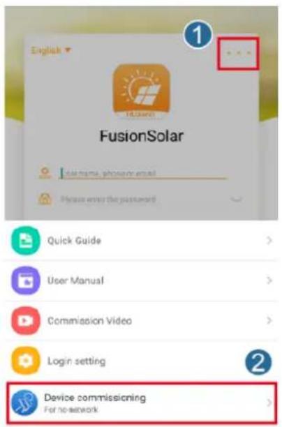
CANCEL
Figure B-2 Method 2: after login (connected to the Internet)
Step 2 Connect to the solar inverter WLAN and log in to the device commissioning screen as the installer user.
NOTICE
- If the mobile phone is directly connected to the SUN2000, the visible distance between the SUN2000 and the mobile phone must be less than 3 m when a built-in antenna is used and less than 50 m when an external antenna is used to ensure the communication quality between the app and the SUN2000. The distances are for reference only and may vary with mobile phones and shielding conditions.
- When connecting the SUN2000 to the WLAN over a router, ensure that the mobile phone and SUN2000 are in the WLAN coverage of the router and the SUN2000 is connected to the router.
- The router supports WLAN (IEEE 802.11 b/g/n, 2.4 GHz) and the WLAN signal reaches the SUN2000.
- The WPA, WPA2, or WPA/WPA2 encryption mode is recommended for routers. Enterprise-level encryption is not supported (for example, public hotspots requiring authentication such as airport WLAN). WEP and WPA TKIP are not recommended because these two encryption modes have serious security defects. If the access fails in WEP mode, log in to the router and change the encryption mode of the router to WPA2 or WPA/WPA2.
Figure B-3 Quick settings
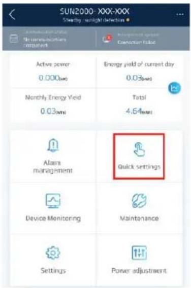
NOTE
- Obtain the initial password for connecting to the solar inverter WLAN from the label on the side of the solar inverter.
- Use the initial password upon first power-on and change it immediately after login. To ensure account security, change the password periodically and keep the new password in mind. Not changing the initial password may cause password disclosure. A password left unchanged for a long period of time may be stolen or cracked. If a password is lost, devices cannot be accessed. In these cases, the user is liable for any loss caused to the PV plant.
- When you access the Device Commissioning screen of the SUN2000 for the first time, you need to manually set the login password because the SUN2000 does not have an initial login password.
----End
C Resetting Password
Step 1 Power off the SUN2000 twice within 3 minutes.
NOTE
- To power off the SUN2000, turn off the AC switch and turn off the DC switch at the bottom of the SUN2000. If the SUN2000 connects to batteries, turn off the battery switch between the SUN2000 and batteries.
- Perform one power-on operation between two power-off operations. After the power-on, ensure that the indicator is blinking green slowly before performing the second power-off operation.
Step 2 Power on the SUN2000. After the SUN2000 is powered on, log in to the app using the initial WLAN hotspot name and password of the SUN2000 within 10 minutes. Then, reset the password and set the router and management system parameters for remote management. If no operation is performed within 10 minutes, all SUN2000 parameters are not changed.
- Resetting user passwords
Log in to the FusionSolar app and go to the Device Commissioning screen. On the password setting screen that is displayed, set the user password.
Figure C-1 Setting the password
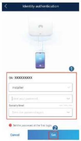
- Resetting the WLAN password
Log in to the FusionSolar app, choose Device Commissioning > Settings > Communication configuration > Inverter WLAN settings, and reset the WLAN password.
Figure C-2 Resetting the WLAN password
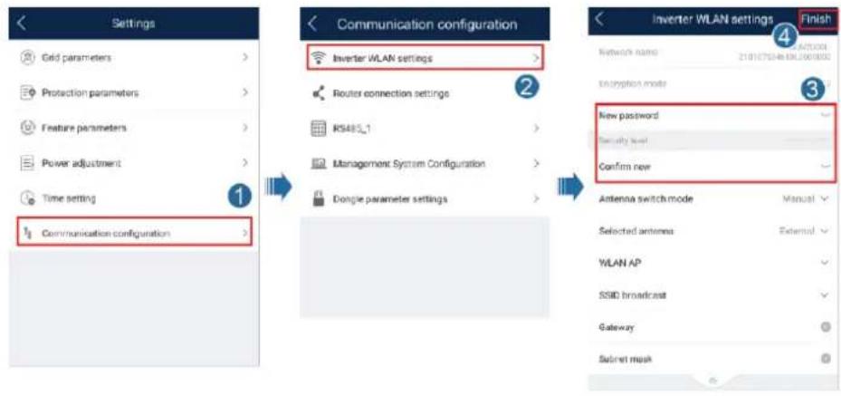
- Setting router parameters
Log in to the FusionSolar app, choose Device Commissioning > Settings > Communication configuration > Router connection settings, and set router parameters.
Figure C-3 Setting router parameters
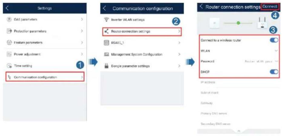
- Setting management system parameters
Log in to the FusionSolar app, choose Device Commissioning > Settings > Communication configuration > Management System Configuration, and set management system parameters.
Figure C-4 Setting management system parameters
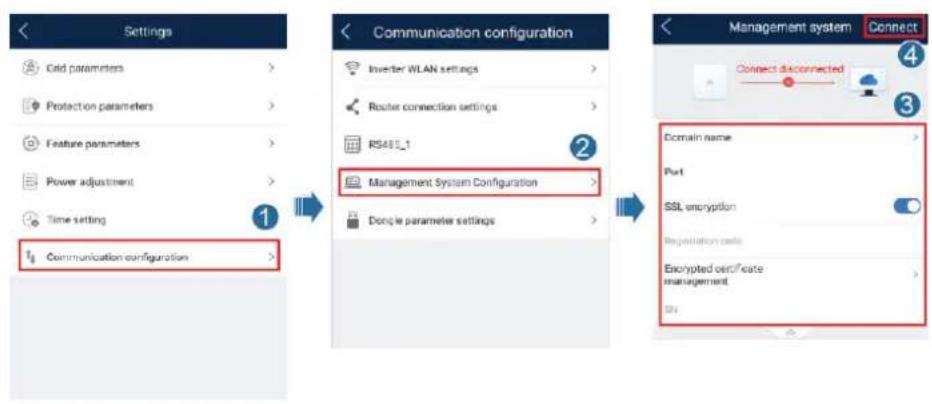
flowchart
graph LR
    A["Settings"] --> B["Communication configuration"]
    B --> C["Management system"]
    C --> D["Connect"]

    subgraph Settings
        A1["Casf parameters"]
        A2["Protection parameters"]
        A3["Feature parameters"]
        A4["Power adjustment"]
        A5["Time setting"]
        A6["Communication configuration"]
    end

    subgraph Communication configurations
        B1["Inverter WLAN settings"]
        B2["Router connection settings"]
        B3["RS48L_1"]
        B4["Management System Configuration"]
        B5["Dongle parameter settings"]
    end

    subgraph Connection Options
        C1["Domain name"]
        C2["Port"]
        C3["SSL encryption"]
        C4["Registration calls"]
        C5["Exempted certificate management"]
        C6["SN"]
    end
----End
D Quick-break Protection
When all PV modules connected to the solar inverter are configured with optimizers, the PV system shuts down quickly and reduces the output voltage of the optimizer to 0 V within 30 seconds.
Perform the following step to trigger quick-break protection:
• Method 1: Turn off the AC switch between the solar inverter and the power grid.
• Method 2: Set the DC SWITCH at the bottom of the solar inverter to OFF.
E Locating Insulation Resistance Faults
If the ground resistance of a PV string connected to a solar inverter is too low, the solar inverter generates a Low Insulation Resistance alarm.
The possible causes are as follows:
- A short circuit occurs between the PV array and the ground.
- The ambient air of the PV array is damp and the insulation between the PV array and the ground is poor.
To locate the fault, connect each PV strings to a solar inverter, power on and check the solar inverter, and locate the fault based on the alarm information reported by the FusionSolar app. If a system is not configured with any optimizer, skip the corresponding operations. Perform the following steps to locate an insulation resistance fault:
Step 1 Power off a solar inverter. For details, see 8.1 System Power-Off.
Step 2 Connect each PV string to the solar inverter and power on the solar inverter. For details, see 6.2 System Power-On.
Step 3 Log in to the FusionSolar app and choose My > Device Commissioning. On the Device Commissioning screen, connect and log in to the solar inverter, and access the Alarm management screen. Check whether the Low Insulation Resistance alarm is reported.
- If the Low Insulation Resistance alarm is not reported one minute after the solar inverter is powered on, go to Step 2 to connect another PV string to the solar inverter for a check.
- If a Low Insulation Resistance alarm is still reported one minute after the solar inverter is powered on, check the percentage for possible short-circuit positions on the Alarm details page and go to Step 4.
Figure E-1 Alarm details
| < Alarm details | |
| Alarm information | |
| Alarm name | |
| Low insulation resistance | |
| Alarm generation time | |
| Alarm ID | Cause ID |
| 2062 | 1 |
| Alarm severity | |
| Major | |
| Possible cause | |
| 1. The PV array is short-circuited to ground; 2. The PV array is in a moist environment and the power cable is not well insulated to ground; | |
| Suggestion | |
| 1. Check the impedance between the PV array output and PE, and eliminate short circuits and poor insulation points. 2. Check that the PE cable for the inverter is connected correctly. 3. If you are sure that the impedance is less than the pre-set protection threshold in a cloudy or rainy environment, log in to the mobile phone app, SmartLogger, or NMS and reset the insulation impedance protection threshold. Current insulation resistance: 0MΩ, possible short circuit position: 98.5%. The short circuit position is valid for a single PV string. If there are multiple PV strings, check the PV strings one by one. | |
NOTE
- The positive and negative terminals of a PV string are connected to the PV+ and PV− terminals of the solar inverter. The PV− terminal represents a possibility of 0% for the short-circuit position and the PV+ terminal represents a possibility of 100% for the short-circuit position. Other percentages indicate that the fault occurs on a PV module or cable in the PV string.
- Possible fault position = Total number of PV modules in a PV string x Percentage of possible short-circuit positions. For example, if a PV string consists of 14 PV modules and the percentage of the possible short-circuit position is 34%, the possible fault position is 4.76 (14 x 34%), indicating that the fault is located near PV module 4, including the previous and the next PV modules and the cables of PV module 4. The solar inverter has a detection precision of ±1 PV module.
Figure E-2 Definition of the percentage of the short-circuit position
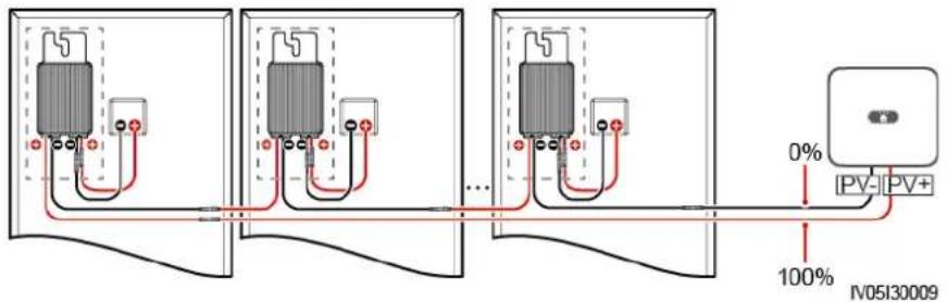
Step 4 Power off the solar inverter and check whether the connector or DC cable between the possible faulty PV modules and the corresponding optimizers, or those between the adjacent PV modules and the corresponding optimizers are damaged.
- If yes, replace the damaged connector or DC cable, power on the solar inverter, and view the alarm information.
- If the Low Insulation Resistance alarm is not reported one minute after the solar inverter is powered on, the inspection on the PV string is complete. Go to Step 2 to check other PV strings.
If the Low Insulation Resistance alarm is still reported one minute after the solar inverter is powered on, go to Step 5.
• If not, go to Step 5.
Step 5 Power off the solar inverter, disconnect the possible faulty PV modules and corresponding optimizers from the PV string, and connect a DC extension cable with an MC4 connector to the adjacent PV modules or optimizers. Power on the solar inverter and view the alarm information.
- If the Low Insulation Resistance alarm is not reported one minute after the solar inverter is powered on, the fault occurs on the disconnected PV module and optimizer. Go to Step 7.
- If the Low Insulation Resistance alarm is still reported one minute after the solar inverter is powered on, the fault does not occur on the disconnected PV module or optimizer. Go to Step 6.
Step 6 Power off the solar inverter, reconnect the removed PV module and optimizer, and repeat Step 5 to check the adjacent PV modules and optimizers.
Step 7 Determine the position of the ground insulation fault.
- Disconnect the possible faulty PV module from the optimizer.
- Power off the solar inverter.
- Connect the possible faulty optimizer to the PV string.
- Power on the solar inverter. Check whether the Low Insulation Resistance alarm is reported.
- If the Low Insulation Resistance alarm is not reported one minute after the solar inverter is powered on, the PV module is faulty.
-
If the Low Insulation Resistance alarm is still reported one minute after the solar inverter is powered on, the optimizer is faulty.
-
Replace the faulty component to rectify the insulation resistance fault.
----End
F
Acronyms and Abbreviations
A
AC alternating current
D
DC direct current
DCI direct current identification
F
FRT fault ride through
H
HVRT high voltage ride-through
I
ID identifier
L
LED light emitting diode
LVRT low voltage ride-through
M
MAC Media Access Control
MPPT maximum power point tracking
P
PE protective earthing
PV photovoltaic
R
RCMU residual current monitoring unit
RH relative humidity
S
SN serial number

- User Manual
- Trademarks and Permissions
- Notice
- Huawei Technologies Co., Ltd.
- About This Document
- Overview
- Intended Audience
- Symbol Conventions
- Change History
- Contents
- About This Document...... ii
- Safety Information....1
- Product Introduction ....7
- SUN2000 Storage....16
- System Installation ....17
- Electrical Connection....31
- Safety Information
- General Safety
- Statement
- General Requirements
- ! DANGER
- Personal Safety
- Personnel Requirements
- NOTE
- Electrical Safety
- Grounding
- DANGER
- AC and DC Power
- Cabling
- Installation Environment Requirements
- Mechanical Safety
- Using Ladders
- Drilling Holes
- Moving Heavy Objects
- Commissioning
- Maintenance and Replacement
- Product Introduction
- Overview
- Function
- Model
- Networking Application
- Supported Power Grid Types
- Component Description
- Label Description
- Enclosure Labels
- Nameplate
- Working Principles
- Schematic Diagram
- Working Mode
- SUN2000 Storage
- System Installation
- Checking Before the Installation
- Checking Outer Packing
- Checking Deliverables
- Preparing Tools and Instruments
- Determining the Installation Position
- Basic Requirements
- Installation Environment Requirements
- Mounting Structure Requirements
- Installation Angle Requirements
- Installation Space Requirements
- Moving a SUN2000
- Procedure
- CAUTION
- Installing a SUN2000
- Installation Precautions
- Wall-Mounted Installation
- Support-Mounted Installation
- Electrical Connection
- Preparing Cables
- Connecting PE Cables
- Precautions
- Additional Information
- Installing a WLAN Antenna
- (Optional) Installing a Smart Dongle
- Connecting an AC Output Power Cable
- Follow-up Procedure
- WARNING
- Connecting DC Input Power Cables
- (Optional) Connecting Battery Cables
- Prerequisites
- (Optional) Connecting Signal Cables
- Context
- Communication Networking Mode
- System Commissioning
- Verification Before Power-On
- System Power-On
- Man-Machine Interaction
- App Commissioning
- Downloading the FusionSolar App
- (Optional) Registering an Installer Account
- Creating a PV Plant and a User
- (Optional) Setting the Physical Layout of the Smart PV Optimizers
- Parameters Settings
- Energy Control
- Grid-tied Point Control
- Battery Control
- Forcible Charge and Discharge
- Control Mode
- Feeding Power into Grid
- AFCI
- Clearing Alarms
- IPS Check (for Italy CEI0-21 Grid Code Only)
- DRM (Australia AS4777)
- System Maintenance
- System Power-Off
- Routine Maintenance
- Troubleshooting
- SUN2000 Disposal
- Removing a SUN2000
- Packing a SUN2000
- Disposing a SUN2000
- Technical Parameters
- SUN2000 Technical Specifications
- Optimizer Technical Specifications
- B Device Commissioning
- Step 1 Access Device Commissioning screen.
- C Resetting Password
- Step 1 Power off the SUN2000 twice within 3 minutes.
- Step 2 Power on the SUN2000. After the SUN2000 is powered on, log in to the app using the initial WLAN hotspot name and password of the SUN2000 within 10 minutes. Then, reset the password and set the router and management system parameters for remote management. If no operation is performed within 10 minutes, all SUN2000 parameters are not changed.
- D Quick-break Protection
- E Locating Insulation Resistance Faults
- F
- Acronyms and Abbreviations
- A
- D
- H
- I
- L
- M
Brand : HUAWEI
Model : SUN2000L 2KTL-L1
Category : Installation solaire