AP4-TY13 - Audio Amplifier PAC - Free user manual and instructions
Find the device manual for free AP4-TY13 PAC in PDF.


| Product Type | Vehicle Audio Interface Module |
| Brand | PAC |
| Model | AP4-TY13 |
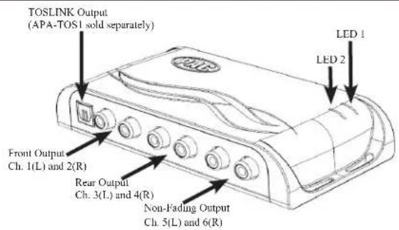
| Number of Pre-amp Output Channels | 6 (3 pairs: Front, Rear, Non-Fading) |
| RCA Output Voltage | 5V RMS (selectable to 4V via DIP switch 2) |
| Remote Turn-On Output | 2A max |
| Input | Factory radio full-range fixed level signals via data bus |
| Supported Features | Fading, balance, equalization, level control, navigation prompts, Bluetooth, voice activation, factory beeps |
| Compatible Vehicles | Toyota with factory amplifier and 24-pin/30-pin harnesses |
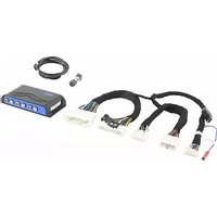
| Included Components | AP4-TY13 module, harness, non-fading level control knob |
| Optional Accessory | APA-TOS1 (TOSLINK fiber optic output) |
| Power Supply | 12V DC from vehicle ignition |
| Current Consumption | Not specified; typical low current |
| Dimensions | Approx. 3 x 2 x 1 inches (module) |
| Weight | Approx. 0.25 lbs |
| Installation Location | Near factory amplifier under left front seat (Toyota) |
| Warranty | Not specified |
| Certifications | Not specified |
| Firmware Update | Via USB and PC app (AmpPRO) |
| Cleaning | Not required; keep away from moisture |
| Safety | Install with ignition off; secure wiring; avoid shorts |
| Repairability | No user-serviceable parts; contact PAC support |
Frequently Asked Questions - AP4-TY13 PAC
User questions about AP4-TY13 PAC
0 question about this device. Answer the ones you know or ask your own.
Ask a new question about this device
Download the instructions for your Audio Amplifier in PDF format for free! Find your manual AP4-TY13 - PAC and take your electronic device back in hand. On this page are published all the documents necessary for the use of your device. AP4-TY13 by PAC.
USER MANUAL AP4-TY13 PAC
Introduction and Features
The AP4-TY13 provides a 6-channel pre-amp output for use with aftermarket audio equipment. Using the full range, fixed level head unit output, in conjunction with data bus messages, the AP4-TY13 delivers a variable 5v RMS pre-amp output with fading, balance, equalization, and level control capabilities. The module also retains audio from other vehicle features such as factory navigation prompts, Bluetooth and Voice Activation. An accessory controlled remote amplifier turn on wire is also provided by the AP4-TY13. When used in conjunction with the APA-TOS1 (sold separately), the module can provide a variable 2-channel fiber optic digital audio output (TOSLINK).
Important Notes
- Toyota Safety Connect (SOS) can easily be retained. See the Tech Brief "AP4-TY SOS Retention" at PAC-audio.com for detailed instructions.
- The factory radio's speed controlled volume, DSP, and surround sound mode are not supported by the AP4 outputs.
- The factory amplifier must remain connected, and in the vehicle after the AmpPRO has been installed.
- Prior to testing, cycle the ignition off and back on again to properly initiate the AP4-TY13.
- The radio's beep setting must be enabled on the factory radio in order to hear the audible tones when making selections through the radio.
- Initially, if the beep through the AP4-TY13 does not match the on / off selection through the radio, cycle the beep to the opposite setting and back, then test again.
- The radio's beep volume and minimum volume levels are set to 0 dB by default. If you are happy with this level in your particular application, additional adjustment is not required. Please refer to the Setup and Configuration section on page 4 for more details.
- The Radio's Nav / VR Voice, incoming E-mail tone, Ringtone, In-Call, Incoming SMS / MMS tone and Incoming SMS Voice volumes can be adjusted through the radio's settings menu as they were prior to installation of the AP4-TY13.
- The remote output is rated at 2A of current. If more current is needed, an external relay must be used.
- Channels 5 and 6 are non-fading outputs. The output level of channels 5 and 6 can be controlled using the supplied level control knob.
Wiring Connection Chart

flowchart
graph TD
    A["24-pin"] --> B["AP4-TY13-HAR"]
    C["30-pin"] --> B
    D["To Amp"] --> B
    B --> E["Remote Turn On Output (2A Max)"]
    B --> F["To Amp Harness"]
    G["PAC"] --> H["Non-Fading RearFront"]
    H --> I["1(L) 2(R) 4(R) 5(L) 6(R)3(L)"]
    H --> J["Non-Fading Level Control Knob"]
    K["To Aftermarket Amplifier"] --> L["1(L) 2(R) 4(R) 5(L) 6(R)3(L)"]
Module Layout

Installation

Set DIP switches to the ON position to activate the corresponding features. Set DIP switches to the OFF position for any features that are not desired.

| Two Channel Mode | 5v / 4v Preout Troubleshooting Not Used | |
| 1 2 3 4 |
- To gain access to the amplifier, reposition the left front seat forward and to the highest position.
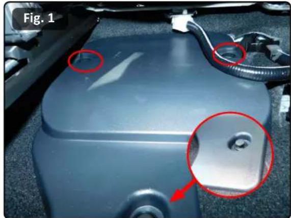
- Locate the factory amplifier cover, remove the 3 push pins that secure the cover into place, and remove the cover to gain access to the amplifier (Fig. 1).
- Disconnect the 30-pin harness and the 24-pin harness from the amplifier. To unplug the 30-pin, you must press the inner release tab and pull the connector's outer release tab at the same time (Fig. 2).
- Connect the AmpPRO harnesses to the vehicle harnesses.
- Connect the AmpPRO harnesses to the factory amplifier.
- Set any feature DIP switches that apply to your install.
a. DIP switch 1 is used for two channel mode. In this mode, both the TOSLINK and front RCA outputs (1 and 2) become non-fading outputs.
b. Set DIP switch 2 on (down) to lower the RCA output voltage to 4v. Leave DIP switch 2 off (up) to keep the RCA output voltage at 5v. See troubleshooting section on page 6 for more details.
c. Set DIP switch 3 on (down) only if the output of the AP4 is too low. Doing this will give you a +8 dB boost on the INPUT of the module.
d. DIP switch 4 is not used and should remain off (up).
-
If you are using the APA-TOS1 (sold separately) refer to the instructions included with that product for its installation.
-
Connect the AmpPRO harness to the module.
- Connect the level control knob to the module and install in an accessible location.
- Connect the signal cables and remote input from the aftermarket amplifier.
- Initially, if the beep through the AP4-TY13 does not match the on / off selection through the radio, cycle the beep to the opposite setting and back, then test again.
- See the Tech Brief "AP4-TY SOS Retention" at PAC-audio.com for detailed instructions for retaining SOS. The Yellow / Black connections are not necessary when using the AP4-TY13.
natural_image
Close-up of a car engine compartment with red-circled features and a small metallic component, labeled 'Fig. 1' (no readable text or symbols beyond label)
Installation (cont.)
Speaker Connections to Aftermarket Amplifier
The AP4-TY13 harness speaker wire outputs are able to be utilized for connecting the aftermarket amplifier to the existing speakers.
- Using the wiring diagram and information below, cut the speaker wires that will be used between the AP4-TY13 30-pin connector that plugs into the OEM amplifier and the 30-pin connector that plugs back into the OEM harness.
- Insulate the cut wires on the amplifier side of harness.
- Extend speaker wires from the aftermarket amplifier outputs and connect them to the appropriate wires in the AP4-TY13 harness.
30-Pin AP4-TY13 Harness - Side that Connects to OEM Harness

Connector Viewed From Wire Side
| Pin Number | Wire Color | Wire Description | Label |
| 8 Blue Subwoofer Speaker | 2 Positive (SW2+) | Subwoofer 2 | |
| 23 Blue / Black Subwoofer | Speaker 2 Negative (SW2-) | ||
| 9 Green Left Rear Speaker | Positive (LR+) | Left Rear Speaker | |
| 24 Green / Black | Left Rear Speaker Negative (LR-) | ||
| 10 Purple Right Rear Speaker | Positive (LR+) | Right Rear Speaker | |
| 25 Purple / Black Right Rear Speaker | Negative (LR-) | ||
| 11 White | Left Front Mid Positive (LF+) | Left Front Midrange | |
| 26 White / Black | Left Front Mid Negative (LF-) | ||
| 12 Gray / Red | Right Front Tweeter Positive (RFTW+) | Right Front Tweeter | |
| 27 Gray / Blue | Right Front Tweeter Negative (RFTW-) | ||
| 13 Brown / White | Subwoofer Speaker 1 Positive (SW1+) | Subwoofer 1 | |
| 28 Brown / Black Subwoofer | Speaker 1 Negative (SW1-) | ||
| 14 White / Red | Left Front Tweeter Positive (LFTW+) | Left Front Tweeter | |
| 29 White / Blue | Left Front Tweeter Negative (LFTW-) | ||
| 15 Gray | Right Front Speaker Positive (RF+) | Right Front Midrange | |
| 30 Gray / Black | Right Front Speaker Negative (RF-) | ||
Setup and Configuration
- Turn the ignition on. LED 1 on the interface will turn on and the +12v remote output will turn on.
- Set the amp gain(s) to the desired level. We recommend using an oscilloscope and test tones to set the amp gain(s). Please refer to the MECP Advanced study guide if you are unfamiliar with this process.
- Check volume, balance, fade and EQ settings.
- If you would like to adjust the radio's beep volume or minimum volume, do so using one of the methods outlined below. If you are happy with the default levels, no adjustments are necessary.
Manually Setting the Radio's Beep Volume
You can manually set the level of the factory radio beeps using the programming button on the side of the interface. If you would like to set the beep volume using the PC app please proceed to the PC App section.
Setting the radio's beep volume using the programming button
- Start with the level control knob turned all the way down (counter-clockwise).
- Press the programming button on the side of the interface.
- LED 1 will turn green and beeps will begin continuously sounding.
- Turn the level control knob clockwise until the desired beep volume level is reached.
- You can now either press the programming button twice or wait ten seconds to exit the settings.
Manually Setting the Minimum Volume
If the minimum volume of the radio (factory radio volume level 1) is too loud, you can manually set the level of the minimum volume using either the programming button on the side of the interface or the factory SWC. If you would like to set the minimum volume using the AmpPRO app, please proceed to the AmpPRO App section.
PLEASE NOTE: Level control knob must be connected to the module in order to set the Minimum Volume.
Setting the minimum volume using the programming button
- Start with the level control knob turned all the way down (counter-clockwise).
- Set the amp gains to the desired level.
- Set the volume on the factory radio to 1.
- Press the programming button on the side of the interface twice.
- LED 1 will turn amber and the chimes will begin sounding every five seconds.
- Turn the level control knob clockwise until the desired minimum volume level is reached.
- You can now either press the programming button once or wait ten seconds to exit the settings.
AmpPRO App
Use of the AmpPRO App allows you to do the following:
- Configure User Interface Options such as:
• Minimum Volume Level
• Chime (Radio Beeps) Volume Level
- Enable / Disable AP4 Chimes (Radio Beeps)
- Enable / Disable factory EQ
- Bass / Mid / Treble boost frequencies and Q factor
- Update Product Firmware
- Read Firmware / Hardware Versions
- You can download the AmpPRO app at : http://aampglobal.com/appdownloads

AmpPRO App (cont.)
PLEASE NOTE: These settings can be adjusted with the module installed in the vehicle, or on the bench. However, it is recommended to make the adjustments with the module installed, and the factory radio on, so that the changes can be heard.
Minimum Volume Level - This allows you to set the minimum volume level of the factory radio (factory radio volume level 1).
Chime Volume Level - This allows you to set the volume of the radio beeps that are heard through the AP4.
Chimes Enabled - This allows you to enable / disable AP4 radio beeps (ie: tone that is heard when pressing radio buttons). This is used when mixing factory and aftermarket speakers. It is also possible to turn the beeps off altogether using the radio's factory settings menu.
3 Band EQ Enabled - This allows you to enable / disable the 3 band factory EQ.
Bass / Mid / Treble Freq / Q Factor - This allows you to set the center frequency that will be adjusted when setting the 3 band factory EQ, as well as the Q Factor for each frequency. The Q Factor determines how many of the adjacent frequencies will be affected when adjusting the selected frequency. The lower the Q Factor, the more frequencies will be affected.
| Available Frequencies and Q Factors | |||||
| Bass Frequency | 60HZ | 500HZ 7.5KHZ | |||
| 80HZ Mid Frequency | 1KHZ 10KHZ | ||||
| Treble Frequency | |||||
| 100HZ | 1.5KHZ 12.5KHZ | ||||
| 120HZ | 2.5KHZ 15KHZ | ||||
| Bass Q Factor | 0.50 | 0.75 | 0.75 | ||
| 1.00 Mid Q Factor | 1.00 Treble Q Factor | ||||
| 1.50 | 1.25 | 1.25 | |||
| 2.00 | 1.50 | ||||
Firmware Updates
The AmpPRO app will also allow you to update the interface with new firmware as it becomes available. Please visit www.pac-audio.com or contact our tech support department to see if there is a firmware update for your interface.
Connect the interface to your PC and select "Firmware", then "Update Firmware". Now select "Select File". Finally, browse to the place where you saved the file and select it. This will begin the updating process. Once finished, disconnect the interface from the PC and resume normal operation.


Restoring Factory Settings
You can restore the interface to factory default settings by pressing and holding the programming button on the side of the module until the status LEDs start blinking red. Once the LEDs start blinking red, release the button.
This reset will restore the following settings to their factory defaults:
• Radio Beeps volume level
- Enable / Disable Factory Beeps
• Minimum volume level
- Enable / Disable factory EQ
• Factory EQ frequency
• Factory EQ Q factor
Troubleshooting
- No audio - Check to see if LED 1 is illuminated. If not, cycle the ignition off and back on.
- Hiss at high amp gain - Set feature DIP switch 2 to the on (down) position to lower the output voltage of the AP4 to 4v. If you still hear the hiss, lower your amp gains until the hiss is gone.
- Cannot hear beeps when pressing buttons on the radio - Go to the Beep On / Off setting in the radio's settings menu and make sure it is set to ON. If it is, set it to OFF and back to ON and test for beeps again. Next, set the beep volume using process outlined in Setup and Configuration, or using the AmpPRO application. If you still do not hear beeps, be sure that you are using the remote output from the AP4 to turn on your aftermarket amplifier.
- Low volume setting on radio is too loud - Set minimum volume using process outlined in Setup and Configuration, or using the AmpPRO application.
- Drastic volume difference between radio sources - The radio stores the volume of the radio source from the last time that source was used. Readjust the volume of the individual sources to the same output level.
| LED Legend | ||
| LED 1 | Action / Color | During Normal Operation |
| Solid Red | Module Active | |
| Solid Green | Chime Volume Adjustment Mode | |
| Solid Amber | Minimum Volume Adjustment Mode | |
| Rapid Blink Any Color | DSP Activity | |
| LED2 | Blink Amber | USB Connection Detected |
| Both LEDs | Alternate Blinking Red | Performing Memory Reset |


- Introduction and Features
- Important Notes
- Wiring Connection Chart
- Module Layout
- Installation
- Installation (cont.)
- Speaker Connections to Aftermarket Amplifier
- Setup and Configuration
- Manually Setting the Radio's Beep Volume
- Setting the radio's beep volume using the programming button
- Manually Setting the Minimum Volume
- Setting the minimum volume using the programming button
- AmpPRO App
- Use of the AmpPRO App allows you to do the following:
- AmpPRO App (cont.)
- Firmware Updates
- Restoring Factory Settings
- Troubleshooting
Brand : PAC
Model : AP4-TY13
Category : Audio Amplifier