
RPK4-FD2201 - Car radio PAC - Free user manual and instructions
Find the device manual for free RPK4-FD2201 PAC in PDF.


| Product Type | Radio Replacement Kit with Climate Control Retention |
| Brand | PAC |
| Model | RPK4-FD2201 |
| Compatible Vehicles | 2015-2018 Ford F-150, 2017-2018 Ford Super Duty (4" screen) |
| Factory Screen Size | 4 inches |
| Retained Features | Steering wheel controls, factory reverse camera, AM/FM reception, factory USB port, HVAC controls |
| Not Retained | SYNC, external temperature, auxiliary input jack (2015 SYNC vehicles), camera zoom |
| Power Supply | 12V DC (vehicle) |
| Audio Output | Speaker-level outputs (factory wiring) |
| SWC Compatibility | Alpine, JVC, Kenwood, Clarion, Pioneer, Sony, Fusion, and others (set via DIP switches) |
| Included Components | Dash panel with HVAC control, circuit board housings, pocket, radio brackets, AM/FM antenna adapter, reverse camera retention harness, ribbon cables, RP4.2 interface, screws |
| Additional Accessory Support | VS41 module (sold separately) for front and blind spot cameras |
| Installation Difficulty | Professional installation recommended |
| Tools Required | 7mm socket, 10mm socket, ratchet, T10 Torx screwdriver, small flathead screwdriver, plastic panel removal tool |
| Software App | RadioPRO PC application for configuration and firmware updates |
| DIP Switch Settings | Required for radio brand selection |
| Climate Control Retention | Requires proper ribbon cable installation; failure causes loss of HVAC |
| Steering Wheel Control Programming | Pre-programmed, optional reassignment via programming button |
| Reverse Camera Retention | Connects to 12-pin or 54-pin plug behind factory monitor |
| Maintenance | Keep clean; avoid using improper screws; follow installation instructions |
| Safety Warning | Use only specified screws; 22mm screws can damage product |
| Spare Parts Availability | Contact PAC for replacement ribbon cables, screws, and other components |
| Warranty | Standard PAC warranty (check product documentation) |
Frequently Asked Questions - RPK4-FD2201 PAC
User questions about RPK4-FD2201 PAC
0 question about this device. Answer the ones you know or ask your own.
Ask a new question about this device
Download the instructions for your Car radio in PDF format for free! Find your manual RPK4-FD2201 - PAC and take your electronic device back in hand. On this page are published all the documents necessary for the use of your device. RPK4-FD2201 by PAC.
USER MANUAL RPK4-FD2201 PAC
Now Including Button Trim Options!

natural_image
Black automotive headbox with plastic components and mounting holes (no text or symbols visible)For Trucks With 2 Separate Buttons

natural_image
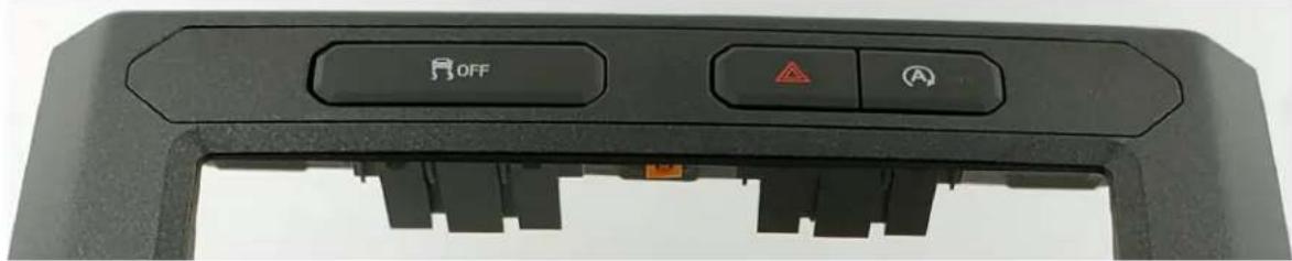
Exterior view of a black plastic mechanical component with two rectangular cutouts (no text or symbols)For Trucks With 3 Separate Buttons

natural_image
Black plastic mechanical component with three rectangular cutouts (no text or symbols visible)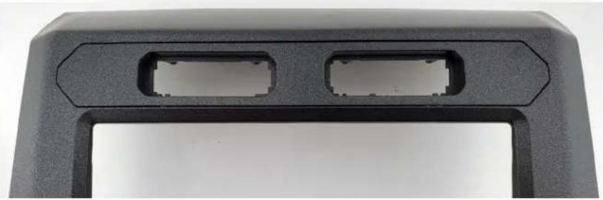
natural_image
Close-up of a black plastic electronic component with two rectangular slots (no text or symbols visible)The following information replaces Step 2 of the assembly section on Page 5 of the RPK4-FD2201 installation instructions.

natural_image
Close-up of a mechanical component with two circular features on top, no visible text or symbolsThe required upper dash button trim panel will depend on whether the vehicle has two or three separate buttons. Insert the appropriate upper dash button trim bezel into the RPK4-FD2201 kit. Use the (2) supplied T10 6mm screws to secure the bezel into place, and insert the buttons that were removed during disassembly (step 1 page 3 of the RPK4-FD2201 installation instructions).
Introduction & Features
The RPK4-FD2201 is a complete radio replacement kit with integrated climate control retention for the 2015-2018 Ford F-150 and 2017-2018 Ford Super Duty equipped with the 4" screen. This kit utilizes the factory HVAC control knobs for a more factory look and experience. This kit also includes all of the modules and cables needed to retain all of the important features of the factory system such as: steering wheel mounted radio controls, factory reverse camera, AM/FM reception, and the factory USB port (if equipped). With the addition of the VS41 (sold separately) you can also add blind spot cameras and a front camera to the aftermarket radio.
Important Notes
- These instructions only apply to Rev. 1.1.1.8 of the product.
- We recommend that you read this manual thoroughly to familiarize yourself with the entire process before beginning installation.
-
Transfer of the factory HVAC knobs, circuit boards, and auxiliary button panel is required. Professional installation is recommended.
-
WARNING! Failure to install the supplied ribbon cables properly will result in LOSS OF or INTERMITTENT operation of CLIMATE CONTROLS! Follow instructions carefully!
-
Only compatible in vehicles equipped with the 4" screen.
-
Does not retain SYNC.
-
Does not retain auxiliary input jack in 2015 vehicles equipped with SYNC.
-
Does not retain external temperature displayed on factory screen.
-
Only one of the reverse camera retention harnesses will be used.
-
Does not retain camera zoom on reverse or bed cameras in Super Duty trucks.
-
Please make your vehicle settings selections before removing the factory radio for optimal installation time. Once the radio has been removed, the vehicle settings, which are normally selected through the factory radio, can be accessed by downloading and installing the PAC Radio PRO application from http://services.aampglobal.com/radiopro/updates/downloads/radiopro_setup.exe. Please see page 13 for further details on the Radio PRO app.
-
Once the radio is removed, the chimes will play through the small dash speaker and not the cabin speakers.
-
Use of improper length screws during kit re-assembly can result in damage to this product. Please pay special attention to Part Three: Step 6, and DO NOT use the 22mm long screws. Damage will occur!! 22mm long screws are only used in Part Three: Step 9.

Components
Tools needed for installation : 7mm socket, 10mm socket, ratchet, T10 torx screwdriver, small flathead screwdriver, plastic panel removal tool.
- Dash Panel with HVAC Control
- Middle Circuit Board Housing
- Bottom Circuit Board Housing
- Pocket (For single DIN applications)
- (x2) Radio Brackets (left and right)
- AM / FM Antenna Adapter
- (x2) Reverse Camera Retention Harness (used only when equipped with factory reverse camera. Only one will be used.)
- (x2) Ribbon Cables
- RP4.2 Interface Harness
- (x8) 6mm Screws
- (x9) Radio Mounting Screws
- USB Retention Cable (if equipped)
- RP4.2 Interface

Installation
Part One: Disassembly of Factory Dash
natural_image
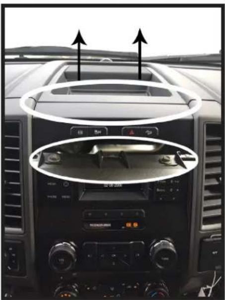
Interior view of a car dashboard with illuminated controls and directional arrows (no readable text or symbols)- Remove front dash panel from vehicle by prying up on the top dash panel with a plastic pry tool, then removing the two 7mm screws located under the top dash panel.
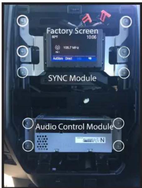
- Remove the factory screen, SYNC module (if equipped), and Audio Control Module (ACM) using a 7mm socket. These parts are no longer needed. They can be stored away in case you ever decide to re-install the factory radio.

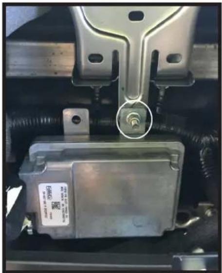
- If vehicle is equipped with a factory camera module, it must be relocated. Remove the three nuts securing it using a 10mm socket.
natural_image
Close-up of a car's internal components, including a metallic vehicle and a battery housing, with no visible text or symbols.- Place the top right mounting bracket onto the previous bottom stud mount, and loosely secure using one of the factory 10mm nuts that you removed in the previous step.
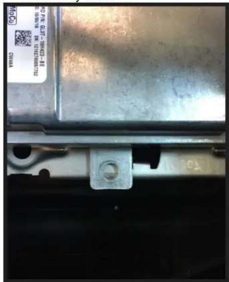
- You can now secure the bottom of the camera module by using a zip tie or by using the fastener of your choice. Once completed, finish tightening the top nut from the previous step.
This is the end of part one. Please continue to the next page to begin part two.

natural_image
Solid black right-pointing arrow shape on white background (no text or symbols)Part Two: Disassembly of Factory Dash Panel

- Remove hazard and traction control buttons from factory dash panel by pushing in on the release tabs. Set aside for later use.
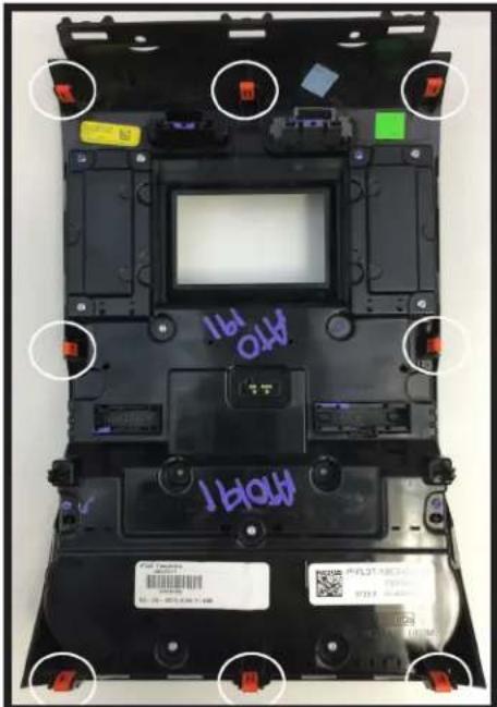
- Remove (8) orange clips from factory dash panel using a small flathead screwdriver. Set aside for later use.

- Remove (15) T10 22mm screws from factory dash panel. Set (3) aside for later use.

natural_image
Close-up of a black handheld device with labeled parts and a control panel (no readable text or symbols)- Make sure that the white line on the temperature control knob is centered at the top. Remove back of factory dash panel by releasing the locking tabs on each side.

natural_image
Interior view of a laptop case showing green circuit board and internal components (no visible text or symbols)- Remove black plastic gear from back of circuit board. Set aside for later use.
natural_image
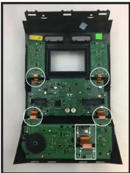
Interior view of an electronic device showing a green circuit board with copper inductors and a central display (no text or symbols visible)- Remove (4) ribbon cables from circuit boards on factory dash panel by pulling out on the white release tabs.
Disassembly of Factory Dash Panel (cont.)

natural_image
Interior view of an open electronic device showing green circuit boards and components (no visible text or symbols)- Remove (6) T10 16mm screws from bottom circuit board. Set aside for later use.

natural_image
Laptop case with exposed green circuit board and two black circular components (no visible text or symbols)- Remove bottom circuit board and set aside for later use.
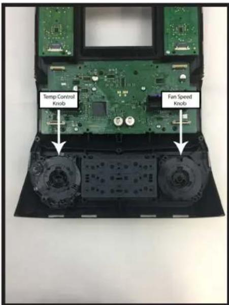
- Remove temperature control and fan speed knobs. Set aside for later use.

- Remove HVAC buttons (make sure the rubber button pad comes with it). Set aside for later use.
natural_image
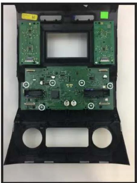
Interior view of a computer case with green circuit boards and circular components (no visible text or symbols)- Remove (6) T10 16mm screws from middle circuit board. Set (2) aside with the (6) from step 7 for later use.

natural_image
Interior view of a black plastic enclosure with green circuit boards and circular cutouts (no visible text or symbols)- Remove middle circuit board and set aside for later use. Make sure that the rubber pads for the buttons and knobs stay behind with the factory dash panel.
Disassembly of Factory Dash Panel (cont.)
natural_image
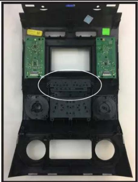
Interior view of a black plastic car body with green circuit boards and a central display panel (no text or symbols visible)- Remove the auxiliary button pad (make sure the rubber button pad comes with it) and set aside for later use.

natural_image
Black automotive air conditioner unit with control panel, buttons, and plastic components (no visible text or symbols)- You may now take the remaining pieces of the dash panel, along with the (16) T10 screws - (12) 22mm and (4) 16mm - and (4) ribbon cables and store them away. These will be needed if you ever decide to reinstall the factory radio. Please do not randomly use these screws when assembling the aftermarket dash kit. Use specified screws only
This is the end of part two. Please continue to the next section to begin part three.

natural_image
Solid black right-pointing arrow shape on white background (no text or symbols)Part Three: Assembly of Aftermarket Dash Kit
natural_image
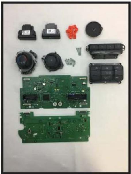
Disassembled electronic components including capacitors, relays, and a green circuit board (no text or symbols visible)- These are the components you should have set aside from part two.

natural_image
Black automotive air vent bay with two circular buttons labeled 'Fire' and 'Air', no visible text or symbols on the main body.- Install the hazard and traction control switches into the new dash kit as shown. Traction control switch goes on the left and hazard switch goes on the right.
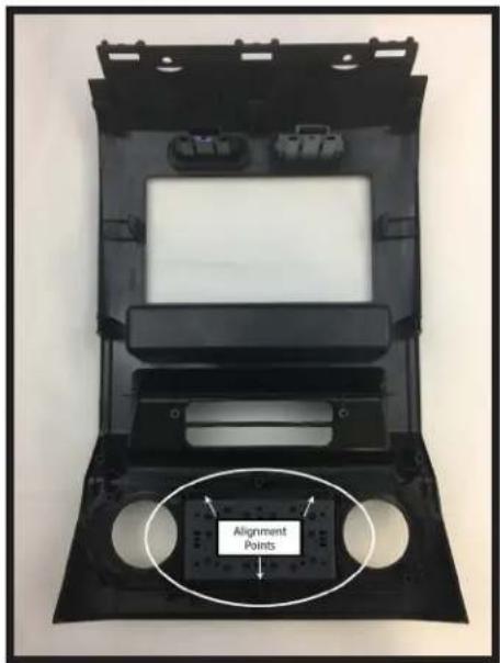
- Flip the panel over and install the HVAC buttons as shown. Make sure the alignment tabs set correctly.
Assembly of Aftermarket Dash Kit (cont.)

natural_image
Interior view of a car air conditioning unit with two circular insets showing internal components (no visible text or symbols)- Install the temperature and fan speed knobs as shown. Please make sure that the white line on the temperature control knob is centered at the top.

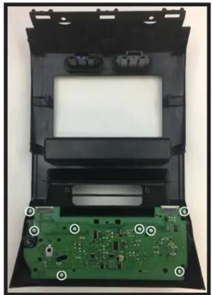
- Install the bottom circuit board as shown. Make sure that the rubber pads on the board fit snugly into the previously installed knobs.
natural_image
Interior view of a device casing showing green circuit board and internal components (no text or symbols visible)- Using the (8) 16mm screws you kept from Part Two:Steps 7 & 11, secure the circuit board to the panel as shown.

natural_image
Close-up of a green circuit board with visible components and a magnified inset showing a mechanical gear assembly (no text or symbols)- Install the black plastic gear as shown. Make sure the alignment mark on the gear is pointing at the gear attached to the temperature control knob.
natural_image
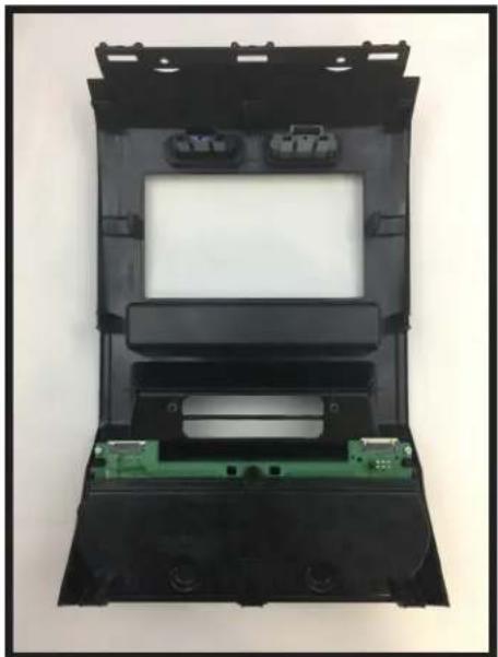
Exterior view of a black plastic enclosure with green circuit board and two connectors (no text or symbols visible)- Install the bottom circuit board housing as shown.


natural_image
Interior view of a device enclosure showing a green circuit board and two circular components (no text or symbols visible)- Using the (3) 22mm T10 screws you Part Two: Step 3, secure the circuit board housing to the panel as shown.

Assembly of Aftermarket Dash Kit (cont.)

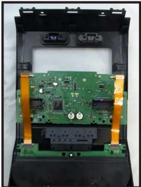
- Connect the (2) supplied ribbon cables to the bottom circuit board as shown. Make sure that the copper contacts on the ribbon cables are facing towards you. Once the cables are seated in the connector, lock them in place by pushing down on the locking tabs.
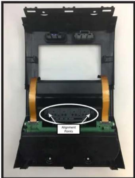
- Install the auxiliary button panel assembly as shown.
natural_image
Interior view of an electronic device showing a green circuit board with gold-colored connectors and components (no visible text or symbols)- Temporarily place the middle circuit board on the kit, just above the auxiliary button panel. Position the (2) ribbon cables as shown. These will need to be connected to the bottom of the middle circuit board in the next step.

natural_image
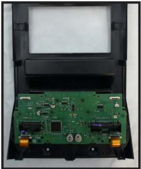
Interior view of an electronic device showing a green circuit board with connectors and labeled components (no readable text or symbols)- Connect the free ends of both ribbon cables to the corresponding connectors on the circuit board as shown. You may need to lift up on the white lock tabs, to insert the ribbon cables. Once the cables are seated a slight click is felt. Then push down on the white locking tabs.
natural_image
Interior view of an electronic device showing a green printed circuit board with visible components and gold connectors (no text or symbols)- Carefully align the middle circuit board over the bottom circuit board as shown.
natural_image
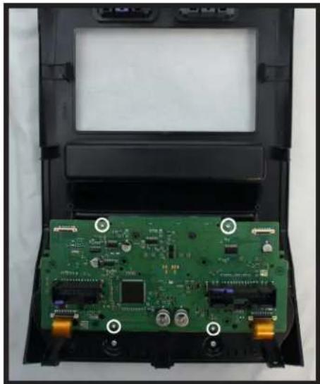
Interior view of a device showing an open circuit board with visible components and mounting holes (no text or symbols)- Using (4) of the supplied 6mm T10 screws, secure the circuit board to the panel as shown.
Assembly of Aftermarket Dash Kit (cont.)
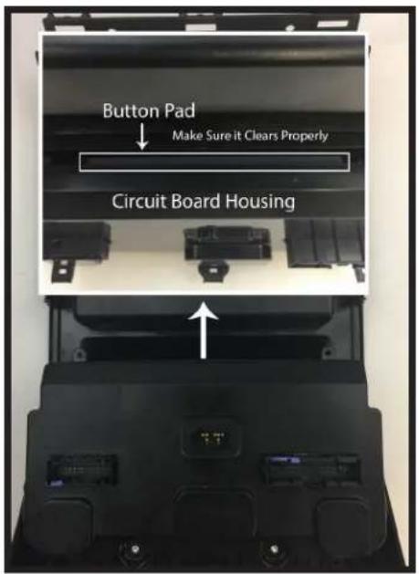
- Install the middle circuit board housing as shown. Make sure that the top of the housing clears the auxiliary button pad during placement.

natural_image
Top-down view of a black automotive airfoil frame with visible internal compartments and mounting points (no text or symbols)- Using (4) of the supplied 6mm T10 screws, secure the housing to the panel as shown.
This is the end of part three. Please continue to the next section to begin part four.

natural_image
Solid black right-pointing arrow shape on white background (no text or symbols)Part Four: Configuring and Wiring the RadioPRO Interface
Module Layout


DIP Switches and Wiring Connections
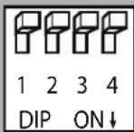
Set DIP switches that match your radio to the ON position
Set all other DIP switches to the OFF position
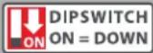
| Alpine | JVC | Kenwood | Clarion | Pioneer/Other | Sony | Fusion |
| 1 | 2 | 1 & 2 | 3 | 1, 2, & 3 | 4 | 1 & 4 |
Other = Advent, BOYO, Dual, Lightning Audio, Rockford Fosgate, Visteon
- The radio select DIP switches on the side of the interface must be adjusted to the proper radio setting before plugging the interface into the vehicle.
- Make all connections as described in the connection chart below. Please see page 12 for a full description of the functions and connectivity of the red / white wire.
- If the vehicle is equipped with a factory reverse camera, connect the included reverse camera retention harness to either the 12-pin or 54-pin plug found behind the factory 4" monitor (only one will be present). Connect the yellow RCA to the aftermarket radio's reverse camera input.
- Connect the SWC output wire according to the chart below (aftermarket radio must support a wired remote input).
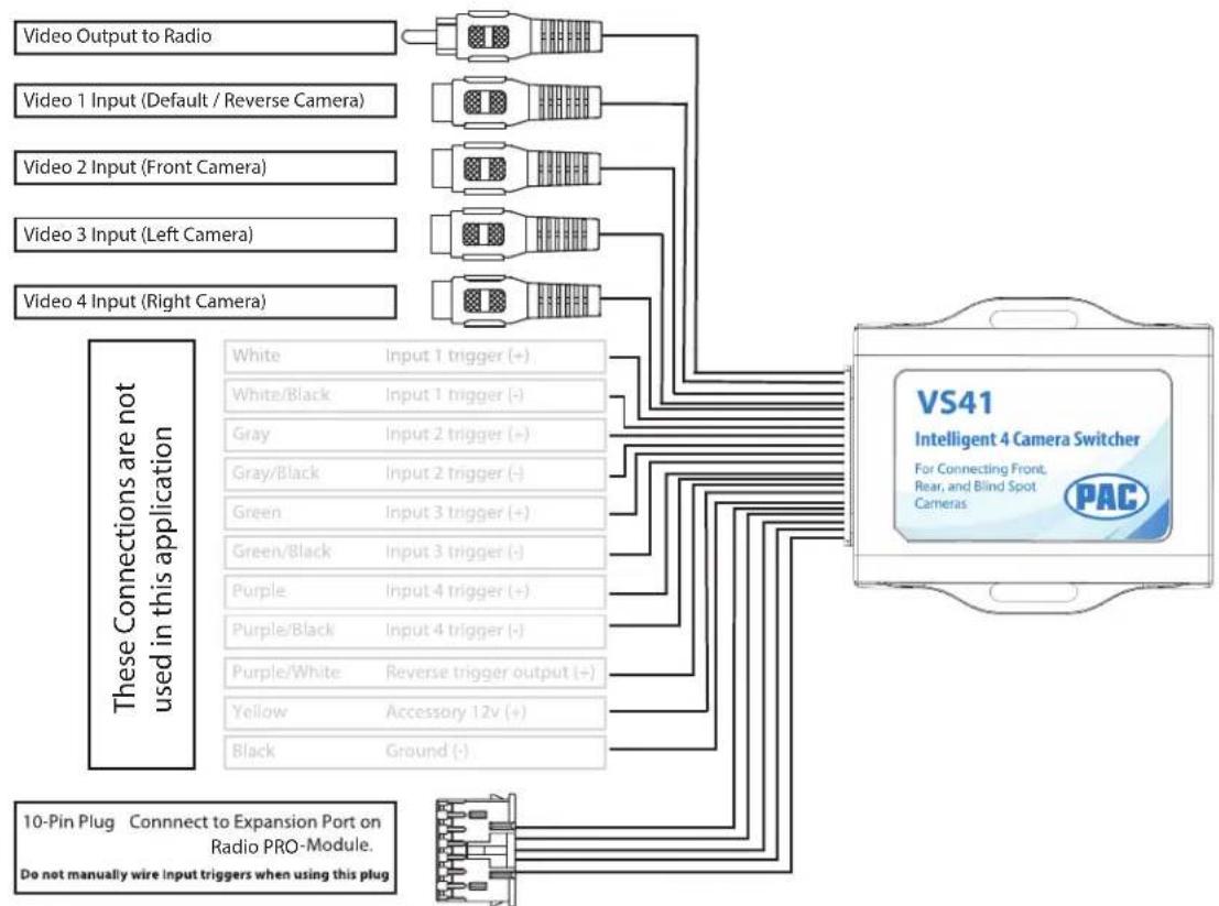
- If you are adding blind spot and / or front cameras, wire up the VS41 (sold separately) as outlined on the next page.
- Once all connections have been made, plug the interface into the vehicle. It is recommended that this be done with the vehicle running. Once the interface has been connected the LED will blink until initialization is complete.
- If you wish to reassign functions to the SWC, or utilize short press long press dual command functionality, or assign the programmable output to a SWC button, follow the programming instructions on page 11.

natural_image
Close-up of a white connector with black, yellow, and red wires (no text or symbols visible)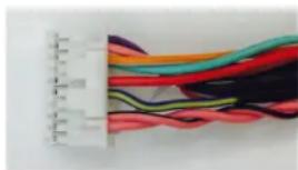
natural_image
Close-up of a white connector with multiple colorful wires (no text or symbols visible)
natural_image
Close-up of a black cable with multiple colored wires (no visible text or symbols)Interface Connector 1
| Red | Accessory Output(10 amps) |
| Yellow | 12v+ |
| Black Ground | |
Interface Connector 2
| 3.5mm Jack SWC Output | |
| Pink MS-CAN + Input | |
| Pink / Black MS-CAN - Input | |
| Blue / Yellow SWC Output | |
| Red / White 12 v+ Programmable Output | |
| Orange / White Illumination Output | |
| Pink Vehicle SpeedSense Output | |
| Violet / White Reverse Output | |
| Light Green Parking BrakeOutput (-) |
Vehicle Connector
| Yellow Battery +12v | |
| Black Ground | |
| Pink MS-CAN + | |
| Pink / Black MS-CAN - | |
| Blue / White Not Used | |
| Brown | Center CH - Input |
| Brown / White | Center CH + Input |
| White | Front L + input |
| White / Black | Front L - input |
| Grey | Front R + input |
| Grey / Black | Front R - input |
| Green | Rear L + input |
| Green / Black | Rear L - input |
| Purple | Rear R + input |
| Purple / Black | Rear R - input |
VS41 Wiring
PLEASE NOTE: Revision 1.0.6.1 of the VS41 is required for this application. If you are adding a front camera and two blind spot cameras, or any combination of the three, to the aftermarket radio, a VS41 is needed (sold separately). Follow the example below to make all inputs work accordingly through the reverse camera input on the aftermarket radio.
flowchart
graph TD
    A["Video Output to Radio"] --> B["White"]
    C["Video 1 Input (Default / Reverse Camera)"] --> D["Gray"]
    E["Video 2 Input (Front Camera)"] --> F["Green"]
    G["Video 3 Input (Left Camera)"] --> H["Purple"]
    I["Video 4 Input (Right Camera)"] --> J["Purple/White"]
    B --> K["VS41 Intelligent 4 Camera Switcher"]
    D --> K
    F --> K
    H --> K
    J --> K
    K --> L["For Connecting Front, Rear, and Blind Spot Cameras"]
    K --> M["PAC"]
    N["These Connections are not used in this application"] --> O["White"]
    N --> P["White/Black"]
    N --> Q["Gray"]
    N --> R["Green"]
    N --> S["Purple"]
    N --> T["Yellow"]
    N --> U["Black"]
    O --> V["Input 1 trigger (+)"]
    P --> W["Input 1 trigger (-)"]
    Q --> X["Input 2 trigger (+)"]
    R --> Y["Input 2 trigger (-)"]
    S --> Z["Input 3 trigger (+)"]
    T --> AA["Input 3 trigger (-)"]
    U --> AB["Input 4 trigger (+)"]
    V --> AC["Input 4 trigger (-)"]
    W --> AD["Reverse trigger output (+)"]
    X --> AE["Accessory 12v (+)"]
    Y --> AF["Ground (-)"]
    Z --> AG["Do not manually wire input triggers when using this plug"]
    AA --> AG
    AB --> AG
    AC --> AG
    AD --> AG
    AE --> AG
    AF --> AG
Steering Wheel Controls
Default Steering Wheel Control Programming
IMPORTANT! The interface comes pre-programmed for all of the vehicles factory SWC functions and does not require programming unless you wish to re-assign the SWC functions, utilize short press long press dual command functionality, or assign the programmable 12v output to a SWC button. The SWC can always be restored to default settings by pressing and releasing the program button on the side of the interface once and waiting 7 seconds for the LED to flash 3 times.
Default SWC Button Assignments
| Alpine JVC Kenwood Clarion Pioneer Sony Fusion | |||||||
| Volume + | Volume + | Volume + | Volume + | Volume + | Volume + | Volume + | Volume + |
| Volume - | Volume - | Volume - | Volume - | Volume - | Volume - | Volume - | Volume - |
| Mode | Source | Source | Source | Source | Source | Source | Source |
| Track + | Track + | Track + | Track + | Search + | Track + | Track + | Track + |
| Track - | Track - | Track - | Track - | Search - | Track - | Track - | Track - |
| Voice | VR | Voicedial | Voice | VR | VR | VR | Power |
| Mute | Mute | Mute | Att | Mute | Mute | Mute | Mute |
| Phone Answer | Receive | Answer | Answer | Send | Answer | Answer | N/P |
| Phone End | End Reject End End End Reject N/P | ||||||
Steering Wheel Controls (Cont.)
Optional Steering Wheel Control Programming
If you wish to re-assign the SWC functions, utilize short press long press dual command functionality, or assign the programmable 12v output to a SWC button, the interface must be programmed in the specific order shown in the chart below. If you come across a function in the chart that your steering wheel does not have, or you do not want to program, press and release the programming button on the side of the interface to skip that function. The LED will flash off and on confirming that you have successfully skipped that function and are ready to proceed to the next one.
Short Press Long Press Dual Command Functionality
This feature allows you to assign two aftermarket radio functions to each of the vehicles SWC buttons. It can be used with as many of the buttons as the user likes or none at all. When this functionality is implemented, quickly pressing and releasing a SWC button will initiate the short press command while pressing and holding a SWC button for longer than two seconds will initiate the long press command. Please note that no long press commands are programmed by default. If you wish to assign dual command functionality to the SWC please follow the programming steps below.
Programmable 12v Output
The Red / White wire on the interface can be programmed via the RadioPRO app to do a pulsed or latched 12v output which can then be assigned to any of the vehicle's factory SWC buttons. When assigned, the factory SWC button will activate the pulsed or latched output to control external accessories. Please refer to page 12 for more details on how to use the app to set this feature.
Optional SWC Programming Procedure
- Turn the key to the ignition position.
- Press and release programming button on the side of the interface. The Status LED will turn green.
- Within 7 seconds, press the button that is to be learned on the steering wheel. The LED will turn red when the button is pressed.
At this point you have two options:
A. For short press functionality: Release the button within 1.5 seconds. The green LED will turn back on.
B. For long press functionality: Hold the button until the LED starts blinking. Release the button and the LED will go back to solid green.
- If you need to program more buttons, repeat step 3 for each additional audio function on the steering wheel.
- If you come across a function in the chart that your steering wheel does not have, or you do not want to program, press and release the program button on the side of the interface to skip that function.
- Once programming is completed, wait seven seconds. The LED will flash three times indicating end of programming.
- Test the interface for proper functionality. Whenever a SWC is pressed the LED on the interface should blink. If any function does not work, repeat the programming steps.
Optional Programming Order
| Alpine JVC | Kenwood | Clarion | Other ■ | Pioneer Sony | Fusion | |||
| 1 | Volume + | Volume + | Volume + | Volume + | Volume + | Volume + | Volume + | Volume + |
| 2 | Volume - | Volume - | Volume - | Volume - | Volume - | Volume - | Volume - | Volume - |
| 3 | Mute | Mute | Mute | Mute | Mute | Mute | Mute | Mute |
| 4 | Preset + | Source | Source | Source | Preset + | Preset + | Preset + | Source |
| 5 | Preset - | Track + | Play | Search + | Preset - | Preset - | Preset - | Track + |
| 6 | Source | Track - | Track + | Search - | Source | Source | Source | Track - |
| 7 | Track + | Band / Disc + | Track - | Band | Track + | Track + | Track + | Audic |
| 8 | Track - | Preset / Disc - | Disc / FM + | Send / End | Track - | Track - | Track - | Power |
| 9 | Power | Select | Disc / AM - | Send | Band | Band | Band | 12v+ Output |
| 10 Enter / Play Attenuation | Answer | End | Answer ☑ | Phone Menu | Reject Call / Source (Bluetooth equipped radios only) | |||
| 11 Band / Program Phone Receive | Voice Dial | VR | END ☑ | Answer Call Answer / End Call | ||||
| 12 | Receive | Phone Reject | On Hook | 12v+ Output | PTT ☑ | End Call | VR | |
| 13 | End | Voice Dial | Off Hook | N/P | VR | 12v+ Output | ||
| 14 | VR | Power | Mute (Multimedia units only) | 12v+ Output | 12v+ Output | |||
| 15 | 12v+ Output | 12v+ Output | Preset + | |||||
| 16 | 12v+ Output | |||||||
| ☐ - Advent, Boyo, Dual, Lightning Audio, Jensen, Rockford Fosgate & Visteon ☑ - Jensen & Advent ONLY | ||||||||
Mounting the Aftermarket Radio


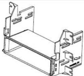
Remove tab (LH & RH) for Double-DIN radio Install (LH-Side bracket shown)

natural_image
Technical line drawing of a mechanical housing or enclosure component (no text or symbols)Mount radio to brackets using supplied screws
natural_image
Technical line drawing of a mechanical bracket assembly (no text or symbols)Attach included pocket to bottom of kit brackets

natural_image
Technical line drawing of a computer case with ventilation slots and drive components (no text or labels)Mount radio to brackets using supplied screws
Testing and Verification
- Turn the ignition on. The LED on the interface will turn on and the +12v accessory wire will turn on.
- Turn on the radio and check balance and fade.
- Verify that all SWC are functioning properly.
- Verify that the programmable 12v+ output is functioning as intended (if connected).
- Verify that all HVAC controls are functioning properly. If the A/C is not blowing cold air, please ensure that the ribbon cables you installed are seated in their connectors properly. Once that is done you may have to drive the vehicle around with the A/C on for up to 20 minutes in order to re-initialize it.
- The LED & radio will turn off when the ignition is turned off.
Camera Control
- If you have the VS41 connected, the cameras can be accessed at any time by using the four buttons you relocated from the factory dash panel. See below for button assignments.
- If the vehicle is equipped with a factory reverse camera, you can use the first button in the bank of four, or the "Mode" button on the SWC, to switch between wide and narrow view, whenever the vehicle is in reverse. PLEASE NOTE: The wide / narrow switch does not function if the reverse camera has been forced. The vehicle must actually be in reverse for this to function.
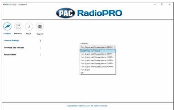
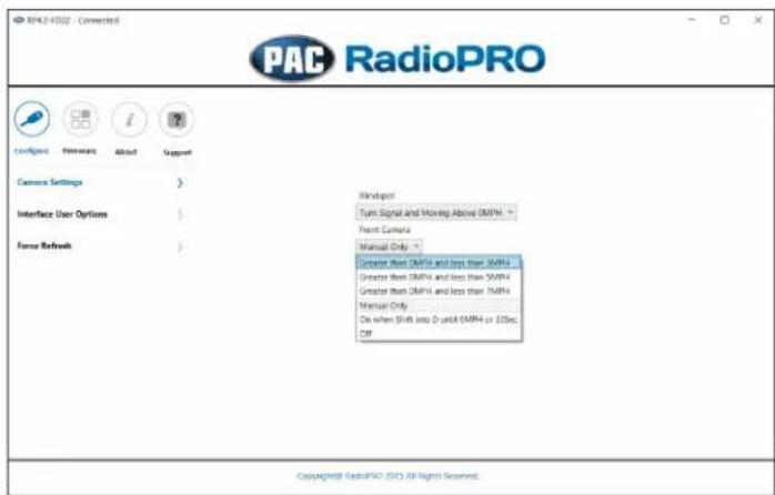
- The default operation of additional cameras is: Blind Spot = on when vehicle moving and turn signal on, Front = Manual Only (using push buttons on HVAC panel). Behavior of these cameras can be changed using the RadioPRO PC application (see next section).

flowchart
graph TD
    A["Toggle Factory Reverse Camera Views (Wide / Narrow)"] --> B["○"]
    C["Force Reverse Camera"] --> D["○"]
    E["Force Front Camera"] --> F["○"]
    G["Force Blind Spot Cameras (Left / Right / Off)"] --> H["○"]
    I["PASSENGER AIRBAG"] --> J["ON"]
    K["○"] --> L["○"]
RadioPRO App
Use of the RadioPRO App in Ford allows you to do the following:
- Configure User Interface Options such as:
- Programmable 12v output (Red / White wire) behavior
• Make vehicle settings selections such as: - Language
• Temperature Units
• Behavior of Front and Blind Spot Cameras (If Present) - Update Product Firmware
- Read Firmware / Hardware Versions
- Access Product User Manuals
Programmable 12v Output (Red/White Wire)
The Red / White wire can be programmed to do a pulsed or latched trigger that is controlled by a user assigned steering wheel control button. Select User Interface Options then set the behavior of the Red / White wire using the drop down menu. Restoring factory settings on the module will default this wires output back to a latched SWC trigger.
Latched - This selection will provide a latched 12v+ output that can be tied to any of the vehicle's SWC. This means that when you press the assigned SWC, the Red / White wire will turn on and remain on until the assigned SWC is pressed again or the ignition is turned off.
Pulsed - This selection will provide a user programmable timed 12v+ output that can be tied to any of the vehicle's SWC. This means that when you press the assigned SWC, the Red / White wire will pulse for the pre-programmed user time. The range for pulse time is 100 milliseconds - 25.5 seconds (.1-25.5).
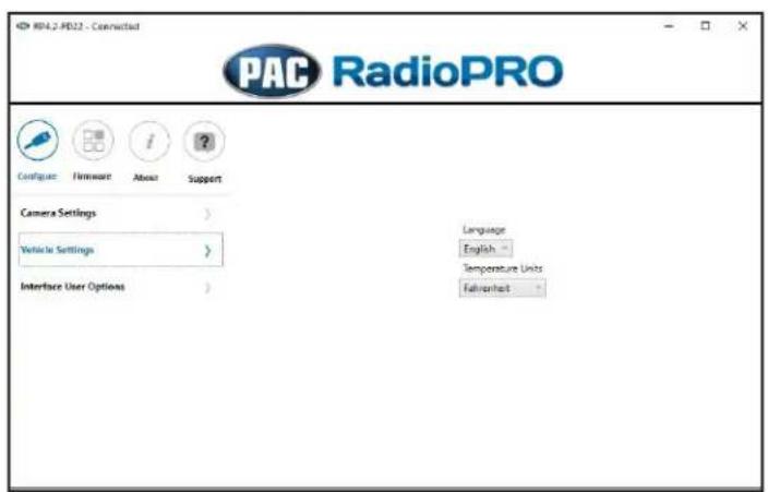
Vehicle Settings
This section allows you to make changes to the Language and the units of things displayed in the Driver Information Center (DIC) in the instrument cluster.


RadioPRO App (cont.)
Front and Blind Spot Camera Behavior (VS41 Required)
If you've added front and / or blind spot cameras using the VS41, the behavior of these cameras can be setup using the RadioPRO PC application.
Firmware Updates
The RadioPRO app will also allow you to update the interface with new firmware as it becomes available. Please visit www.pac-audio.com or contact our tech support department to see if there is a firmware update for your interface.
Connect the interface to your PC and select "Update Firmware". Now select "Select File". Finally, browse to the place where you saved the file and select it. This will begin the updating process.


Restoring Interface Factory Settings
You can restore the interface to factory default settings by pressing and holding the programming button on the side of the module until LED 1 starts blinking red. Once the LED starts blinking red, release the button. You must release the button while the LED is blinking red in order to perform the reset.
This reset will restore the following settings to their factory defaults:
- SWC Mapping
• Programmable 12v+ Output (Latched) - Front Camera and Blind Spot camera behavior
Troubleshooting
- Factory HVAC not working - Please be absolutely CERTAIN that the provided ribbon cables are seated properly and not mis-aligned or installed backwards. Ensure that both HVAC boards are seated properly, and that the alignment tab for the temperature knob is positioned properly according to the steps on Page 6 of this manual.
- Steering wheel controls inoperable - Ensure that the DIP switches are set properly according to page 9 of this manual.
- Reverse Camera inoperable - Ensure that the provided reverse camera retention harness is connected to both the vehicle connector (the one behind he factory screen) and the aftermarket radio.
- Camera view mode switching inoperable - This feature is not retained by the RPK4.2-FD2201.
| LED Pattern | State | Action |
| LED 1 solid red | Active | N/A |
| LED 1 flashing green | SWC Activity | N/A |
| LED 2 solid red | Programmable 12v output active | N/A |
| LED 1 flashing red | Resetting | N/A |
| LED 2 flashing amber | USB connected | N/A |
| Off No activity | Ensure Key is in ignition position. If so, verify that there is 12v and ground on the yellow and black wires. |


- Now Including Button Trim Options!
- Introduction & Features
- Important Notes
- Components
- Installation
- Part One: Disassembly of Factory Dash
- Part Two: Disassembly of Factory Dash Panel
- Disassembly of Factory Dash Panel (cont.)
- Part Three: Assembly of Aftermarket Dash Kit
- Assembly of Aftermarket Dash Kit (cont.)
- Part Four: Configuring and Wiring the RadioPRO Interface
- DIP Switches and Wiring Connections
- VS41 Wiring
- Steering Wheel Controls
- Default Steering Wheel Control Programming
- Steering Wheel Controls (Cont.)
- Optional Steering Wheel Control Programming
- Short Press Long Press Dual Command Functionality
- Programmable 12v Output
- Optional SWC Programming Procedure
- At this point you have two options:
- Mounting the Aftermarket Radio
- Testing and Verification
- Camera Control
- RadioPRO App
- Use of the RadioPRO App in Ford allows you to do the following:
- Programmable 12v Output (Red/White Wire)
- Vehicle Settings
- RadioPRO App (cont.)
- Front and Blind Spot Camera Behavior (VS41 Required)
- Firmware Updates
- Restoring Interface Factory Settings
- Troubleshooting
Brand : PAC
Model : RPK4-FD2201
Category : Car radio