ESA 300 - Door Dormakaba - Free user manual and instructions
Find the device manual for free ESA 300 Dormakaba in PDF.


| Product Type | Automatic Sliding Door |
| Brand | Dormakaba |
| Model | ESA 300 |
| Controller | ESA II |
| Operation | Full Breakout (emergency egress) |
| Power Supply | 120 V AC, 60 Hz (typical) |
| Door Configuration | Two sliding panels (SX) and one sidelight (SO) |
| Glazing | Glass panels with removable stops |
| Safety Compliance | ANSI A156.10 |
| Roller System | Overhead track with eccentric carrier and anti-riser wheels |
| Breakout Mechanism | Both sliding panels can swing outward for emergency exit |
| Sensors | Motion detectors and safety beams (programmable via BEA remote) |
| Installation | Header bolted to jambs, floor track anchored |
| Maintenance | Clean track, adjust roller tension, lubricate as needed |
| Breakout Force | Adjustable roller catch, not to exceed ANSI standards |
Frequently Asked Questions - ESA 300 Dormakaba
User questions about ESA 300 Dormakaba
0 question about this device. Answer the ones you know or ask your own.
Ask a new question about this device
Download the instructions for your Door in PDF format for free! Find your manual ESA 300 - Dormakaba and take your electronic device back in hand. On this page are published all the documents necessary for the use of your device. ESA 300 by Dormakaba.
USER MANUAL ESA 300 Dormakaba
natural_image
Line drawing of a multi-level glass door with four panes and a top shelf (no text or symbols)ESA300
Full breakout automatic sliding door with ESA II controller
Installation Manual
DL2844-030 - 05-2022
| EN |
ToolsRequired:
Screwdrivers
SmallStraight(FlatBlade)-forTerminalBlockwiring
2Phillips(Crosspoint)-forvarious#8,#10,and#14screws
Wrenches/Sockets
7/16"-for#1/4-20HexHeadboltsattachingheadertojambs
1/2"(13mm)-for#5/16HexHeadboltsattachingendstopsandoperatorparts
15/16"wrench-forcarrierandanti-riserolleradjustment
AllenWrenches
3mm-for“SX”&“SO”rollercatchadjustment
1/8"-for"SO"armstop&“SX"bottompivot
5/32"-for"SO"toppivot
5mm(3/16")-for"SO"armpivotscrew
7/32"-for"SX"breakoutadjustment
5/16"-forcarrierandanti-riserolleradjustment
ElectricDrillwiththefollowingdrillbits-
9/64"(or#28)-forinstallingsensors&“SO”bottomrollerstop
5/32"(or#22)-forinstalling#10sheetmetalscrewsintoadjacentstorefront
13/64"(or#7)-forinstalling#14sheetmetalscrewsintoadjacentstorefront
1/4"-forclearanceholesinjambs
82degreeCountersink
ImpactDrillwiththefollowingmasonrybits-
1/4"-for#10screwanchors
5/16"-for#14screwanchors
Level-suggested4'minimum
StepLadder-4'or6'
TapeMeasure
CaulkingandApplicationGun
ElectricalWireS trippers/Cutters-forsensorwiring
Grease[tohold"SX"bottomguideblockonshaft]
BEAUniversalRemoteControl-foradjustingsensors
SuggestedFastenersRequired-(Notsupplied)
JambAttachmentScrews-
14X2-1/2"PHSMS(PocketJambs)
14X3"FHSMS(TubeJambs)
OptionalAnchorsformasonry
ThresholdAttachmentScrews
10X1-1/2"FHSMS
OptionalAnchorsformasonry
HeaderAttachmentScrews
14X1-1/2"HHSMS
14FlatWasher
ConstructionShims-forsquaringdoorframeinopening

Components-Overview
⑩OperatorUnit59 ◯ SlidingPanelFloorGuide ◯
②EndTube(Jamb)Extrusions610BearingPivot MotionDetector
③CoverExtrusion711LatchDevice ○ Program-Panel ○
④Sidelight8FloorRail12BearingPivot

natural_image
Technical line drawing of a mechanical frame assembly with three circular insets showing internal components (no text or symbols)2
HeadertoJambAssembly
Fasten the header unit to the jambs using (5) 1/4-20 x 1" hex bolts per side. (7/16" socket/wrench required.)

Assembly
①Placetheheader&jambassemblyintotheroughopening.
②Levelallsidesandshimasrequired.
③Fastenassemblyintoroughopening,afterverifyingunitislevelandplumbinalldirections.
④Placefloortrackinposition.
Findhighestfloorelevationandshimaccordingly.
Themountingoftheoperatorortotheroughopeningmustmeet applicablebuildingcodesandstandards.


Sidelightmounting
①-② Align "SO" panel 90^ to the "SX" track and 80^ to the vertical jamb. Place "SO" panel onto bottom pivot mounted on the jamb.
③InsertBeamwiresintotoppivot, bushingandverticallythroughtheheader. Attention: Becarefulnottodamagethesafetybeamcable.

SecuringtheSidelight
①Push "SO" Panel vertically to align with jamb. Attention: Becarefulnottodamagethewires.
② Rotate upper "SO" arm and lightly fasten to screw plate located in header.
③ Align and plumb "SO" Panel.
④ Tighten (3) 1/4-20 x 5/8 fasteners in "SO" top pivot, securing "SO" Panel to header using 5/32" Allen wrench.
⑤ Loosen fastener. Close "SO" panel and align "SO" magnet/latch sub-assembly. Tighten fastener using 12 " socket/wrench. For roller catch tension adjustment, see Page 13.
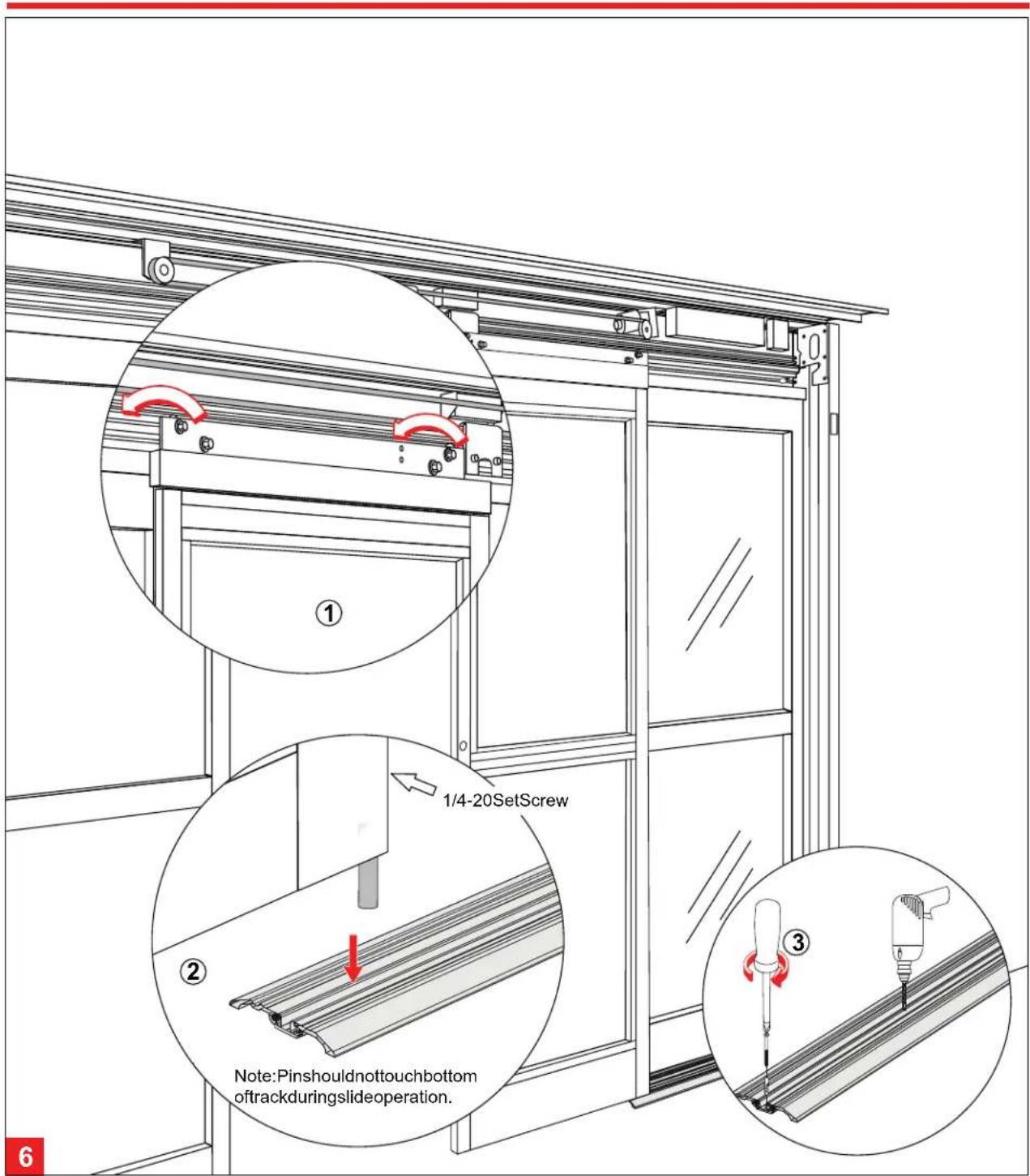
Hangingthe“SX”panel
① Lift“SX”panelandplacerollersontorollertrackinheader.
②Findthehighestspotalongtrack.Placesmallscrewdriverbelow“SX”pivot,loosensetscrewandre-tightenwhen“SX”bottomguidepinreachesscrewdriver (1/8"Allenwrenchrequired).
③Aligntrackwithjamb.Fastenandanchorbottomtracktofloor.
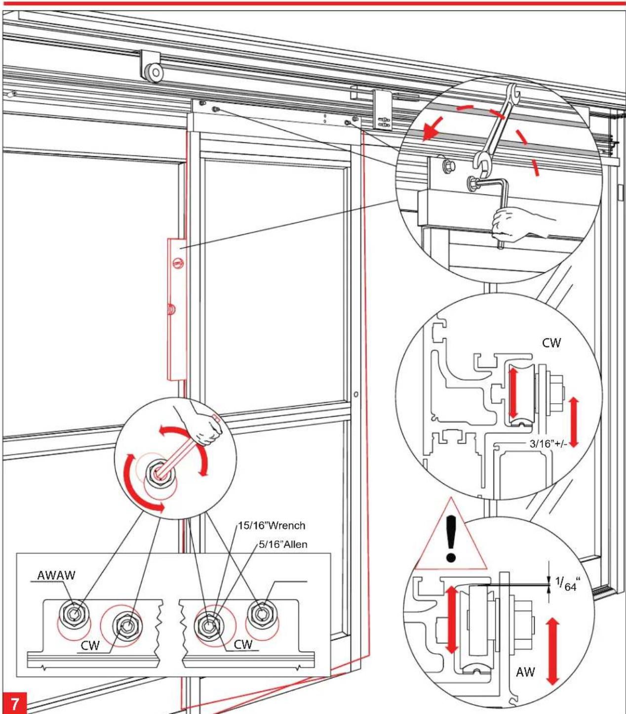
VerticalAlignmentforSXpanel
Using the eccentric carrier wheel (CW), and the anti-riser wheel (AW), level the sliding panel. Tighten hex nuts to secure the adjustment.
Adjustmentoftheanti-riserroller:
Theanti-riserrollers should not contact the top track any where along the slide path of the door.


“SX”PanelCenterlineAdjustment&“SO”BottomLatchInstallation
① With the lower belt bracket securely fastened, and the upper belt bracket in its loose position, the "SX" panels can be properly adjusted to their center position. After panels are centered, fasten upper belt bracket to carrier. (7/16" socket or wrench required.)

Glazing
① Removetheglassstopsfromexteriorside(4peropening).
② Centertheglassinopening.
③Properlyblockand/orcushionglassedges.
④Presstheglassstopsintoplace, startingwiththehorizontalstops, thenfollowwiththeverticalstops.

10
AdjustmentoftheBreakout-Unit
- Loosen the set screws (a, b & c) to prevent interference while adjusting door. (7/32" Allen wrench required.)
- Use the adjustment screw (d) to lift (CW), or lower (CCW), the leading edge of door.
- Continue adjustment until the re-latch profiles are properly aligned.
- Tighten all set screws (a, b & c) until tight and secure.
Recheck the latched position alignment and readjust as necessary.

AdjustmentoftheRollerCatch
Align the roller catches as illustrated, using the adjustment screws. (3mm Allen wrench tool required.)
Pay close attention to the disengagement, or breakout force.
Do not exceed ANSI A156.10 standards.

AdjustmentoftheEndStops
End stops are installed at the factory. Adjustments should be made by loosening the bolt and sliding the stop to the appropriate position. Be sure adjustments are made symmetrically to the door opening, while providing proper finger safety perANSIA156.10 Standards. ( 12 " socket or wrench required.)
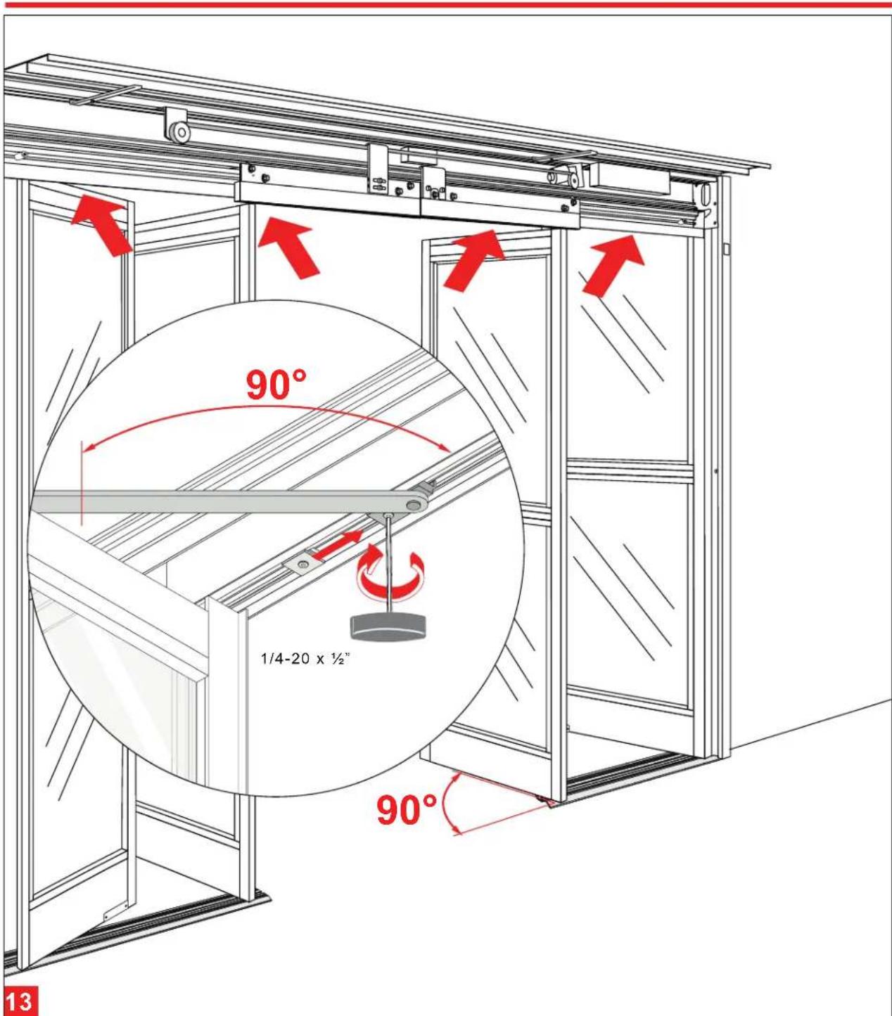
“SX” and “SO” Panel Breakout Adjustment
- Open "SX" & "SO" panels to 90°.
- Move arm stop blocks to engage arm. (1/8" Allen wrench required.)
- Secure stop blocks.

14
"SO"InterlockClipAdjustment
① Loosen "SO" interlock clip fasteners.
② Slide interlock clip on "SO" panel, or "SX" panel, as necessary. Correct adjustment prevents the "SO" panel from breaking out when the "SX" panels are closed, but allows the "SX" panels to breakout when closed.
③ Secure all fasteners when doors are properly adjusted. (Phillips screwdriver required.)
ESA300 Full Breakout Automatic Sliding Door Installation Manual
This page left intentionally blank.
- ESA300
- ToolsRequired:
- 2Phillips(Crosspoint)-forvarious#8,#10,and#14screws
- SuggestedFastenersRequired-(Notsupplied)
- 14X2-1/2"PHSMS(PocketJambs)
- 14X3"FHSMS(TubeJambs)
- 10X1-1/2"FHSMS
- 14X1-1/2"HHSMS
- 14FlatWasher
- Components-Overview
- HeadertoJambAssembly
- Assembly
- Sidelightmounting
- SecuringtheSidelight
- Hangingthe“SX”panel
- VerticalAlignmentforSXpanel
- “SX”PanelCenterlineAdjustment&“SO”BottomLatchInstallation
- Glazing
- 10
- AdjustmentoftheBreakout-Unit
- AdjustmentoftheRollerCatch
- AdjustmentoftheEndStops
- “SX” and “SO” Panel Breakout Adjustment
- 14
- "SO"InterlockClipAdjustment
Brand : Dormakaba
Model : ESA 300
Category : Door