HSW-GP - Door Dormakaba - Free user manual and instructions
Find the device manual for free HSW-GP Dormakaba in PDF.


| Product Type | Sliding door system (sliding partition with pivoting end panel) |
| Brand | Dormakaba |
| Model | HSW-GP |
| Category | Door |
| Installation Type | Ceiling-mounted track rail on steel substructure |
| Panel Type | Glass panels with single-point fixings |
| Track Rail Fixing Interval (Straight) | Approx. 300 mm |
| Track Rail Fixing Interval (Stacking Area) | Approx. 100 mm |
| Carrier Attachment Torque | 25 Nm (M10 hexagonal socket screw) |
| Single-Point Fixing Tightening Torque | 15 Nm (countersunk fastener) |
| Height Adjustment Range | Via floor spring (+4 mm) and plastic shims |
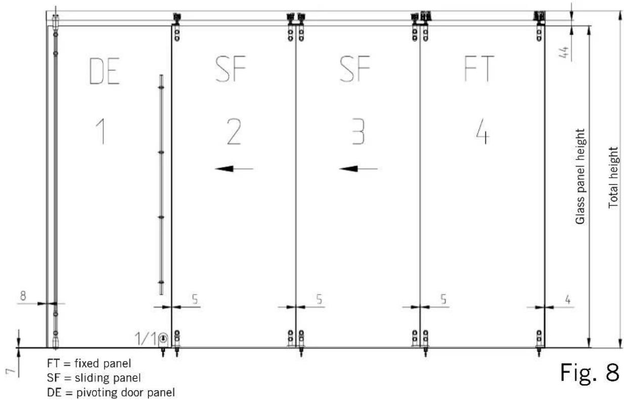
| Panel Clearance from Wall (Pivoting End) | 8 mm |
| Panel Clearance from Wall (Sliding End) | 3 mm |
| Clearance Between Panels | 5 mm |
| Eccentric Socket Hole Diameter | 25 mm (depth 30 mm) |
| Eccentric Socket Offset from Glass Centerline | 43.5 mm |
| Maintenance | Keep locks and bolts in good order; regularly clean floor keeps; lubricate as needed |
| Roller Replacement | Possible via removable maintenance end piece |
| Safety Features | Stop lugs must face outer edges; torque values must be observed; correct alignment critical |
| Weight Capacity | Ceiling substructure must accommodate total panel weight (specific value not given) |
Frequently Asked Questions - HSW-GP Dormakaba
User questions about HSW-GP Dormakaba
0 question about this device. Answer the ones you know or ask your own.
Ask a new question about this device
Download the instructions for your Door in PDF format for free! Find your manual HSW-GP - Dormakaba and take your electronic device back in hand. On this page are published all the documents necessary for the use of your device. HSW-GP by Dormakaba.
USER MANUAL HSW-GP Dormakaba
HSW-GP Installation instructions
Note: The as-delivered condition is indicated in the manufacturing drawing enclosed.
1. Ceiling substructure for track rail and installation of the track rail:
The track rail must be bolted over its entire length (including the stacking track area) to a correctly aligned horizontal (longitudinally and transversely) ceiling steel substructure (e.g. DORMA substructure system).
The steel substructure should be designed to accommodate the total weight of all the panels both in the stacking area and in the partition section. The fixing point intervals for the track rail should be approx. 300 mm along the straight sections and approx. 100 mm in the stacking area.
Caution: All the track joints (except the maintenance end piece, Section 5, page 7) must be provided with connection pins (a) in order to ensure a flush transition between the track sections and thus smooth sliding panel operation. (Fig. 1)

natural_image
Technical line drawings of mechanical components, including heat exchanger and heating element assembly (no text or symbols)2. Mounting the glass panel fittings (Fig. 2A):
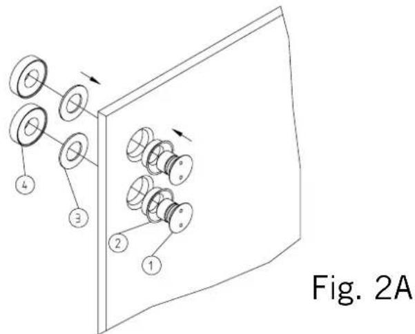
A Mounting the single-point fixings to the glass:
Insert clamping collar (2) together with the tapered countersunk fastener (1) in the glass bore. Place the intermediate layer (3) in the nut (4) and screw the nut onto the countersunk fastener. Using the special wrench, pre-assemble and then tighten with a torque wrench (tightening torque = 15 Nm).
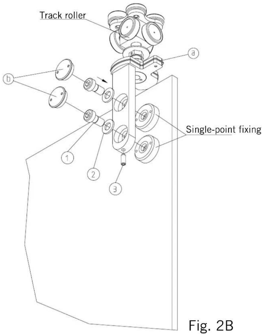
B Installing the carriers (Fig. 2B):
Loosely attach the carrier to the single-point fixings using M10 hexagonal socket screw (1) and washer (2). Use 7 mm Allan key. This enables the panels to be vertically aligned by means of set screw (3) once threaded onto the track. After alignment (Section 8), tighten hexagonal socket screw to a torque of 25 Nm. The stop lugs (a) must face towards the outer edges of the glass panels.
Tap caps (b) onto the socket screws with a rubber mallet.
Ca Installing bottom strap (a) and floor bolt (b) (Fig. 2Ca):
A Using M10 hexagonal socket screws (2), mount bottom strap (1) to the single-point fixings (7 mm Allan key, screw tightening torque 25 Nm).
Tap caps (3) onto the socket screws with a rubber mallet.
B Mount floor bolt (4) to the single-point fixings using M10 hexagonal socket screws (5) and countersunk fastener (6) (7 mm Allan key, screw tightening torque 25 Nm).
Tap caps (7) onto the socket screws with a rubber mallet.
Caution: Bear in mind the direction of travel of the panels and ensure that the stop lugs are facing out.

Cb Mounting a fixed panel (Fig. 2Cb):
Install eccentric sockets (bolt keeps) in the floor as per Section 9. Hang the fixed panel from the track at the top rollers. Insert the spigot of the fixed panel bottom strap (1) in the eccentric socket and fix with M10 hexagonal socket screws (2) to the single-point fixings (7 mm Allan key, screw tightening torque 25 Nm). Tap caps (3) onto the socket screws with a rubber mallet. Ensure correct handing (see details A + B) and ensure that the stop lugs (a) are facing out.

3. Mounting of floor spring (BTS) and floor pivot (Fig. 3a+b):
For the floor spring (BTS), a recess must be provided (see drawing) which is subsequently covered with a stainless steel plate.
Adjust the floor pivot (a) to the distance of 65 mm indicated.
Loosen fixing screws (b), move floor pivot and re-tighten screws.
Adjust the height using the shims provided (3 shims of 1 mm thick each).
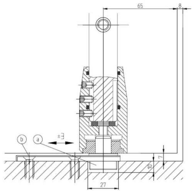
Fig. 3a

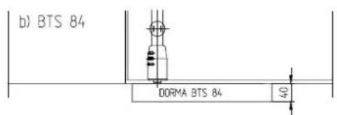

Fig. 3b
4. Mounting the pivoting door panel (Fig. 4a+b)
a) Preparation: Install the top bearing sleeve (1) (pre-assembled on track-rail (2)), and floor pivot (3) or floor spring (BTS) as per instructions.
b) Slide bottom pivot sleeve (A) over bottom pivot rod (3) to full limit of travel. In so doing, ensure that the slot engages with the set screws. Secure using the set screws (4 mm Allan key).
c) Slide top pivot sleeve (B) over top pivot rod. Ensure compliance with the correct mounting position: the flattened side of the sleeve and the threaded bores for the single-point fixings face the glass.
d) Calculate the intermediate tube length = height of glass panel -575 mm.
e) Bolt pivot rods (4) with intermediate tube (5) and bottom pivot sleeve onto the glass panel.
f) Place the pivoting door panel with bottom spigot in the floor pivot bearing or floor spring (BTS).
g) Slide the top pivot sleeve up in accordance with diagram (B) and secure with set screws (4 mm Allan key).
h) Alignment:
Adjusting the door height: Via floor spring +4 mm (see floor spring fixing instructions;
4 adjustment screws).
Further door height adjustments possible using plastic shims between spindle section and pivot rod – removal of door panel necessary; ensure compliance with top door clearance!
Zero position: Via floor spring
Bottom side clearance: Via floor spring
Top side clearance: Via centering single-point fixings at the top pivot rod (2 mm)
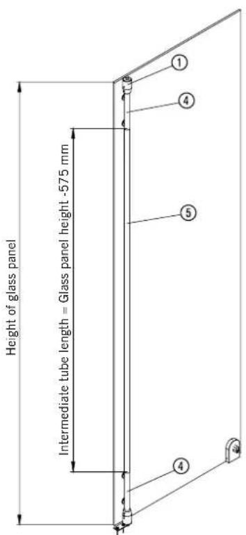
Fig. 4a
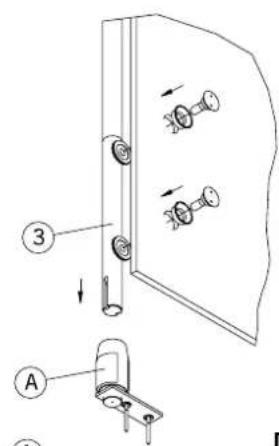
A

Fig. 4b
B
5. Roller replacement (Fig. 5):
The maintenance end piece (b) can be removed for the replacement of defective rollers. The guide plate must always be attached.

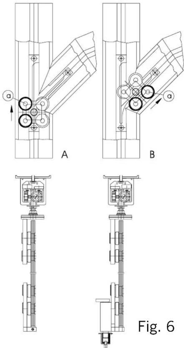
6. Track roller arrangement:
The arrangement of the track rollers is of decisive importance at the stacking area entry point.
A Roller for straight-through section = high track rollers (a), external
B Roller for diversion to internal stacking area track = high track rollers (a), internal, on the side of the stacking area
7. Threading the panels onto the track (Fig. 7):
Thread the panels with mounted rollers onto the track using the opening provided by detaching the maintenance end piece.
Height adjustment:
Loosen nut (b) (17 mm Allan key) and adjust the height via nut (a) (17 mm Allan key). Counter-clockwise rotation = height increases; clockwise rotation = height decreases.

Fig. 7
8. Lateral alignment of the panels
Align the pivoting end panel DE to provide an 8 mm clearance from the wall. Slide the last panel SF to its end position and align to provide a 3 mm clearance from the wall. The clearance between the panels should be 5 mm in each case.
9. Installing the eccentric sockets (Fig. 9):
The standard system uses eccentric sockets for bottom locking. Mark the requisite positions of the eccentric sockets plumb below the lock bolts.
(Offset: Glass centre line to centre line of eccentric socket = 43.5 mm)
Version a) Drill holes 25 mm dia., 30 mm deep for eccentric sockets, and 8 mm dia. for anchor plugs. Insert eccentric sockets (double eccentric), align and fix with central screw in anchor plug.
Version b) Mount eccentric sockets in continuous recessed channel (provided by others).

10. System maintenance and panel operation
In order to ensure functional reliability over the long term, please comply with the following instructions:
-
Ensure that locks and bolts are kept in good working order.
-
Regularly clean keeps for locks and bolts located in the floor.
Sliding the panels:
When closing the sliding partition, always lock each panel in position before moving the next one along.
The panels are very easy to move and should not require any force.
- HSW-GP Installation instructions
- Ceiling substructure for track rail and installation of the track rail:
- Mounting the glass panel fittings (Fig. 2A):
- B Installing the carriers (Fig. 2B):
- Ca Installing bottom strap (a) and floor bolt (b) (Fig. 2Ca):
- Cb Mounting a fixed panel (Fig. 2Cb):
- Mounting of floor spring (BTS) and floor pivot (Fig. 3a+b):
- Mounting the pivoting door panel (Fig. 4a+b)
- Roller replacement (Fig. 5):
- Track roller arrangement:
- Threading the panels onto the track (Fig. 7):
- Lateral alignment of the panels
- Installing the eccentric sockets (Fig. 9):
- System maintenance and panel operation
- Sliding the panels:
Brand : Dormakaba
Model : HSW-GP
Category : Door