
Pearl Insert - Heating EUREKA - Free user manual and instructions
Find the device manual for free Pearl Insert EUREKA in PDF.


| Product Type | Wood Heater Insert (Masonry & Zero Clearance Installation) |
| Brand | Eureka |
| Model | Pearl Insert |
| Package Dimensions (Masonry) | 1075(W) x 660(D) x 800(H) mm |
| Package Dimensions (ZCC) | 915(W) x 695(D) x 1025(H) mm |
| Weight (Appliance Only) | Over 200 kg |
| Fuel Type | Dry hardwood (moisture content below 20% recommended) |
| Fan | 3-speed rotary switch with thermostat override; temperature-sensitive auto on/off |
| Power Supply | 240V AC (standard Australian outlet) |
| Firebox Construction | Steel firebox with cast iron liners (rear and side) |
| Baffle System | 8mm steel plate + 13mm DuraBlanket + 12mm silica board |
| Door Glass | Ceramic glass with 6mm OD sealing rope |
| Paint | Stovebrite Metallic Black (code 6309), heat-resistant |
| Flue Requirements | Minimum 4.6m height from floor protector; 150mm diameter; clearance to combustibles 25mm |
| Minimum Hearth Depth | 550mm in front of fascia (combustible floor) or 300mm if elevated ≥175mm |
| Safety Features | Overfire warning; door seal; non-combustible cladding required; flue cleaning recommended annually |
| Maintenance | Clean glass with damp cloth or wet ash; clean flue annually; replace door rope and glass as needed |
| Warranty | Limited 2-year warranty on firebox (subject to terms); 12-month on other components (excluding glass, firebrick, baffle plate if damaged by impact) |
| Country of Manufacture | Australia (AF Gason Pty Ltd) |
Frequently Asked Questions - Pearl Insert EUREKA
User questions about Pearl Insert EUREKA
0 question about this device. Answer the ones you know or ask your own.
Ask a new question about this device
Download the instructions for your Heating in PDF format for free! Find your manual Pearl Insert - EUREKA and take your electronic device back in hand. On this page are published all the documents necessary for the use of your device. Pearl Insert by EUREKA.
USER MANUAL Pearl Insert EUREKA
Eureka Pearl for masonry installation
Package dimensions: 1075Wx660Dx800H
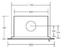
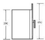
Eureka Pearl for ZCC installation
Package dimensions: 915Wx695Dx1025H
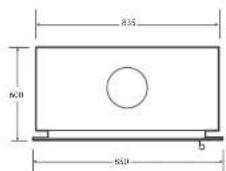
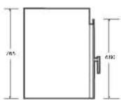
WARRANTY
- Subject to clause 2 & 3 of this warranty, A.F. Gason Pty Ltd. ACN 800-607-556 warrants the following components of its bestes against defects in workmanship and/or materials for the following parts from the date of purchase:
2) the foreign for two years
a) the point factor for a period of 12 months if the purchaser has followed the reductions provided by Game in the operation and litigation instructions must, and
a) all other components for 12 months except the glass, fire brick lining or battle plate R. In the opinion of Gason, these items have been damaged by impact.
- This extended warranty does not apply;
a) if the heater is purchased from a person who has not been authorised by Gason to sell its products
b) It in the opinion of Gason, the heater or any other component has been subject to abuse, misuse, alteration, modification or has not been installed, operated or maintained in
to owners other than the original purchase.
- If you believe that the buyer you purchased contains a manufacturing defect and you wish to make a claim under the warranty, please contact an act-hceived Gaoan service
centre to a range for an assessment.
- If, after observing the heater, there determines that the heater contains a manufacturing fault, there may at its disclosure.
a) replace the heater.
of repair or replace specific components of the heater or
e provide a full refund.
- Parks replaced under warranty are warranted for the balance of their original warranty period.
A. If at the discretion of Geven, the letter or any part meets to be replaced, serviced or repeated at an authorized Geven service, come, then the person claiming under this
=mostly must pay all codes associated with
At returning the healer, and
to the choice at selection of any case or perceived best.
Our goods come with guarantees that cannot be excluded under the Australian Consumer Law. You are entitled in a replacement or refund for a major failure and for comparability for any other reservoirly focuses the loss in damage. You are also entitled to have the goods opened or replaced if the quality fails to be of acceptable quality and the failure does not amount to a major failure.
Any benefits you receive under these warranties are in addition to other rights and remedies that you may have a consumer under law in relation to the heater to which these warranties re are.
These warranties are given by
AF Gascn Pty Ltd
Blake Street
Jinlan VIC 3377
Please contact us if you have any queries on:
Phone: 03 97633200
or email us via the "Contact Us" section of our website: www.gason.com.au
AF Gason Pty. Ltd. reserves the right to modify or alter specifications, material etc. In the interest of product improvement.

natural_image
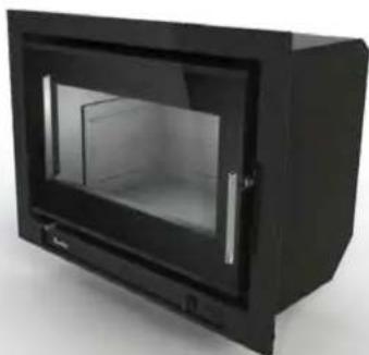
Exterior view of a black rectangular oven or cabinet with glass doors (no text or symbols visible)Pearl Insert Masonry & Zero Clearance Installation
Operation & Installation Instructions
Please keep these instructions for future reference.Rev|C 232345
*Compliance Plate is located on the rear of the appliance fascia or on ZCC.
Pearl Insert 2

WARNING
Read and follow these instructions carefully before installing and using this appliance.
To aid heater installation, remove door, baffle system and cast iron liners to reduce overall heater weight.

WARNING
Safety Warnings
- A flue fire with resulting damage may occur if the appliance is not installed, operated and maintained as per this booklet.
- Never place combustible materials such as wood, paper or furniture near the appliance.
- This appliance is designed to burn dry wood. Do not burn rubbish, driftwood, flammable liquids or any substance containing salts or corrosives.
- This appliance must not be installed and operated in an area where kerosene, petrol, paint thinner or other flammable liquid is used or stored.
• The flue system must be inspected and cleaned annually or sooner if required. Failure to do so could result in an excessive buildup of creosote which may result in a flue fire, which may damage the flue or cause damage to your home. - The surface of the appliance becomes hot during operation. Do not touch the surface of this appliance. Keep children away from this appliance during operation. Do not allow anyone to operate this appliance who is not familiar with this instruction booklet.

WARNING
Paint Curing and Care
Your heater is coated with the best available heat resistant paint. Even though the paint has been baked after application, it may require further temperature curing. It may, if you overfire the heater on its first fire, discolour. For your first two or three firings, never exceed medium air setting and always have the fan on when above low burn. Do not wipe the heater while the paint is curing. After the paint has cured the only maintenance required to maintain the heater's finish is to wipe it with a soft cloth. Do not use any commercial cleaners or solvents on the paint finish.
We are proud of the presentation of our products. If at any time you need to freshen up the paint, your local dealer has touchup paint available for purchase. This heater is painted in stovebrite Metallic Black - code 6309.
If you have any enquiries, please contact the dealer from whom you purchased your heater:
PLEASE COMPLETE:
Dealer Name
Dealer Address
Phone:
Please attach your original purchase dockets to this booklet for future reference.
Pearl Insert 15
Firewood
Getting the most out of your firewood
Firewood is a sustainable source of energy and when used correctly can provide a cost effective form of heating in your home. Too often poor heating results and operational issues are attributed to using unseasoned wood which leads to excess smoking, causing creosote buildup and dirty glass. Wood should be stored in a dry place where good ventilation is available. Freshly cut wood should be stored for between 12-24 months before burning.
Use only hardwood with your Eureka Pearl.
Thermal efficiency
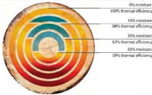
A wood's efficiency does not depend only on its type, but also on its moisture content as well as the temperature of the combustion chamber. To achieve a greater efficiency and longer burn cycle out of your Eureka Pearl, without the emissions of hazardous particulates, your wood must be well seasoned.
Ideally, wood should not be burnt when its moisture content is above 20%. A moisture meter to measure moisture content is a handy addition.
An example of available thermal efficiency for a piece of wood as a fuel source at varying moisture levels.
polar_bar
| Condition | Percentage (%) | |---|---| | 0% moisture | 0 | | 100% thermal efficiency | 100 | | 10% moisture | 10 | | 88% thermal efficiency | 88 | | 30% moisture | 30 | | 63% thermal efficiency | 63 | | 50% moisture | 50 | | 39% thermal efficiency | 39 |Figure 14
The combustion process of burning wood
When wood is heated up to approximately 100 degrees celsius, moisture begins to evaporate from the fuel. There is no heating value from the wood at this point. As moisture releases from the wood, it reduces the efficiency of the combustion process robbing heat energy from the wood. This demonstrates the importance of dry and well seasoned wood. As firebox temperatures reach 250-300 degrees celsius, wood solids begin to break down and release volatile gases which ignite and produce heat.
From 300+ degrees celsius, the main energy available from wood is released when fuel vapors containing up to 60% of the wood's potential heat is released.
Understanding combustion principles and learning how to manipulate various conditions surrounding the operation of your Eureka Pearl enables you to achieve maximum comfort and efficiency from your Australian made wood heater.
Pearl Insert 14
Troubleshooting
- Noisy Fan
Turn the power off and remove the three pin plug from the power point. Remove door and carefully place to one side. Remove the four M8 Cap Screws that hold the fascia onto the firebox. Remove the fascia. Remove switch mount panel. Disconnect the wiring loom via the plastic joiner. Unscrew the wing nuts which hold the fan in position and remove the fan. Clean any dust with a dry paint brush and vacuum the fan blades. Clean around the motor. After completion place two or three drops of sewing machine oil on the shafts at the bearings. Replace the fan in reverse to the removal.
• Fan not working
Check the power connection with another appliance. If the power point is ok, shift focus to the fan or the switches. Move thermostat switch into the 'Override' position, and select one of the three fan speeds. If the fan fails to function, isolate power as above, remove fascia to gain access to loom. Check that the terminals on the loom and both switches are firmly connected. If the fan still fails to function, remove the fan and switches by firstly removing knob off the rotary switch by pulling it away from the heater. Undo the holding nut and pull the switch out.
Squeeze locator tabs together on the rear of the thermostat switch and push through outside of pedestal. Disconnect the wiring from the power lead and remove the fan. Convey the same to the authorised Eureka Dealer from whom you purchased your unit for service. Replace in the reverse order.
• Air control jamming
Access to the air slide is available when the door is opened.
There are three screws holding the air slide in place. Undo them and remove the air slide. Wipe any ash or dust that may have accumulated on the back of the air slide or on the face of the heater. If any burns have developed on the back of the air slide or on the face of the heater, rub them off with fine wet and dry sand paper till you have a smooth surface and edges. Replace the air slide and make sure the washers and spacers are on the bolts when you screw the bolts back into the face of the heater. Do not apply any type of lubricant to the air slide whatsoever as this will attract dust and make the slide stick.
• No overnight burn
Remove the air slide as per air control jamming and check that the air slide is hard against the face of the heater. If it is loose, tighten up the bolts holding the air slide to the face of the heater. Do not overtighten.
Check that the door rope has an even indentation from its contact with the face of the firebox. If it is uneven and it appears as though air could leak through the seal, the door hinge and latch can be adjusted or the door rope may need to be replaced. Refer door adjustments and rope replacement instructions.
• Excessive ash build up
Some woods will give large amounts of ash despite how you run the heater. Others will give you very little. Use the wood which is most convenient for you, as long as it is dry. After a period of time you will get to know when to empty your unit. Bark will give you excessive ash. Try not to burn it. If you are burning wood that gives you charcoal, you may find that after running the heater say for 8 hours at maximum burn rate, the charcoal builds up excessively. An overnight burn will reduce this charcoal back to a fine ash. If you are not ready to shut down for an overnight burn when you next fuel the stove, load the stove with only one piece of wood and lay it across the firebox on top of the charcoal. Open the air control wide open and you will find the charcoal will burn down with the one piece of wood. Repeat the process until the ash level is significantly reduced.
- Excessive smoking - smoke entering the room maybe caused by:
- Insufficient length of flue (Flue to be 4500mm minimum underneath the base of heater to underside of cowl) Increase height of flue
- Flue downdraught - Consult dealer or increase height of flue.
- Creosote build up in flue - Remove cowl and clean flue as per cleaning instructions. Check moisture content of wood.

Overfiring
NEVER OPERATE THE HEATER WITH THE DOOR LOOSE, OR SUCH THAT THE FIREBOX IS NOT AIR TIGHT. OVERFIRING COULD RESULT IN DETRIMENTAL WEAR AND TEAR ON THE FIREBOX AND FLUE SYSTEM.
Pearl Insert 3
Installation

Installation
This heater is to be installed into a masonry fireplace or a Eureka Zero Clearance Cabinet.
THE INSTALLATION OF THIS APPLIANCE MUST BE CARRIED OUT AS PER THIS MANUAL AND THE FLUE MANUFACTURER'S SPECIFICATIONS.
WE RECOMMEND THAT YOU USE A QUALIFIED INSTALLER TO CARRY OUT THE INSTALLATION.
If you have any other enquiries, please contact the dealer from whom you purchased your heater.
THIS APPLIANCE WEIGHS IN EXCESS OF 200 KILOGRAMS. EXTREME CARE SHOULD BE TAKEN WHEN HANDLING THE APPLIANCE.
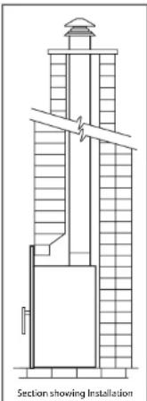
Figure 1. Masonry Installation
AF Gason Pty. Ltd. accepts no liability whatsoever for any interpretation of AS/NZS 2918:2001. It is important you understand these installation instructions and minimum clearances to combustible materials before selecting a position for your Eureka Pearl, to ensure safe and correct installation is achieved.
Installation permit
Depending on your local authority requirements, a permit may be required for the installation of your heater. It is your responsibility to arrange the same.
Installation into existing or masonry fireplace
The Eureka Pearl Insert can be installed into a masonry fireplace with a flue system that is in accordance with the relevant sections of AS/NZS 2198:2001. No combustible or heat sensitive material maybe placed closer then 1410mm from the top of the hearth/base of the appliance and 55mm either side of the appliance's fascia.
In a masonry fireplace installation, the minimum hearth depth of 550mm from the front of the fascia panel must be achieved. In the instance the fireplace is raised above a combustible floor, and it is desirable to reduce the hearth depth, please refer to the elevated installation instructions on page 5 for hearth reduction information.
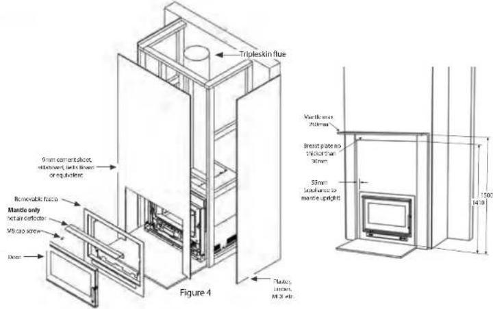
For detailed mantle clearance dimensions, refer Figure 4 on page 6.
If installing the Eureka Pearl under a combustible mantle, a hot air deflector must be attached onto the front of the fascia.
Installation Into Zero Clearance Cabinet - ZCC
The Eureka Pearl Insert can be installed in conjunction with a Eureka ZCC into a wall enclosure directly onto a floor or elevated above a floor.
The Eureka Pearl Insert conforms to AS/NZS 291B:2001 Appendix B, when the appliance is placed in relation to combustible surfaces as per these installation instructions.
For additional clearance details, or access to the Eureka Pearl Insert Conformance Certificate, please contact your local Eureka Dealer from whom you purchased your heater.

Brick Removal
IF BRICKS REQUIRE REMOVAL WHEN PREPARING THE FIREPLACE, ENSURE THAT YOU DO NOT EXPOSE COMBUSTIBLE MATERIALS BEHIND THE BRICKWORK OR WEAKEN THE INTEGRAL STRUCTURE OF THE CHIMNEY.
Pearl Insert 4
Installation (Continued)
Clearance to combustibles & Zero Clearance Cabinet (ZCC) Installation
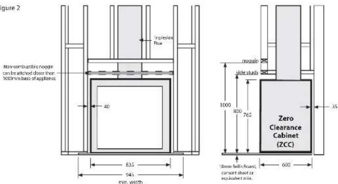
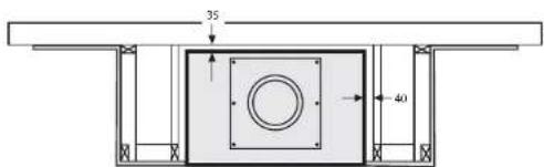
Below, Figure 2 shows an example of how the Eureka Pearl Insert with ZCC should be placed in relation to combustible materials - plaster, wallpaper, timber, MDF etc. These clearances from the ZCC to combustible materials must not be reduced.
In the instance non-combustible or fire retardant material is used, clearances to the appliance can be reduced. It is recommended that a clearance of 25mm or larger between the appliance is always achieved to ensure air can circulate around the wood heater during operation.
Cladding
The front wall of the enclosure between the appliance base and the first noggin (1000mm above appliance base) must be clad with non-combustible material such as cement sheet, vallaboard or Bellis Board of minimum 9mm thickness. This non-combustible cladding must extend horizontally a minimum of 62mm either side of the ZCC. It may be more practical to clad the entire front face of the enclosure with 9mm non-combustible material.
Figure 2
Pearl Insert 13
Basic Spare Parts
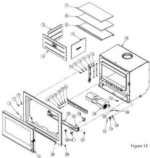
| Ref. | GPN | Description | Ref. | GPN | Description |
| 1 | 221328 | Rubber Grommet Blind | 20 | 907400 | Washer Flat 18 x 10 |
| 2 | 922313 | Screw M8 x 20 | 21 | 232584 | Air Slide Panel |
| 3 | 907300 | Washer Flat 8 x 17 | 22 | 230568-10 | Fascia Fill Pannel |
| 4 | 235529 | Door Assy | 23 | 213151 | Tek Screw 10-16 x 16 |
| 5 | 231032 | Cast Iron Liner - L/H & R/H | 24 | 213049 | Switch - 3 Positions |
| 6 | 231030 | Cast Iron Liner - Rear | 25 | 227074 | Switch Knob |
| 7 | 230932 | Calcium Silicate Baffle | 26 | 232037 | Switch - 2 Positions |
| 8 | 232182 | Durablanket Baffle | 27 | 203651 | Grommet Cord Grip |
| 9 | 230260 | Steel Baffle Plate | 28 | 231819/231820 | Fascia Assy Mas/ZCC |
| 10 | 235542 | Insert Assy | 29 | 213321 | Rubber Grommet |
| 11 | 917308 | Screw Set M8 x 20 | 30 | 203903 | Twin Barrel Fan |
| 12 | 907414 | Washer flat 8 x 20 | 31 | 214289 | Thermostat Switch |
| 13 | 910106 | Washer Star M8 | 32 | 213146 | Wing Nut M6 |
| 14 | 230980 | Hinge | 33 | 917119 | Screw Set M5 x 20 C/S |
| 15 | 234101 | Hinge Shim Plate | 34 | 234342 | Door Catch Assembly |
| 16 | 231804 | Air Slide Rod | 35 | 234016 | Latch Shim |
| 17 | 917209 | Screw Set M6 x 20 | 36 | 906201 | Washer Flat 1/4 x 3/4 |
| 18 | 212974 | Spring | 37 | 203914 | Tek Screw 14-20 x 22 |
| 19 | 213098 | Air Slide Spacer |
Maintaining & Servicing your Eureka (Continued)
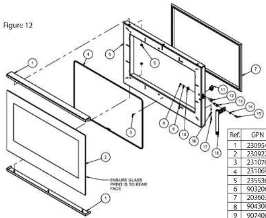
Replacing your glass
- Open door and lift free of hinge.
- Place door face down on a soft flat surface to protect paintwork and glass.
- Remove glass retainers by removing x6 M6 whizlock nuts.
- Lift door frame away from glass. Note how the 6mm OD glass sealing rope is placed around the door frame - dispose of old glass safely.
- Fit new 6mm OD glass sealing rope onto the door frame with new x6 dart clips. Ensure clips are positioned with pointed extrusion facing towards the edge of the door frame.
- Place the glass back onto the door frame with the 6mm OD door sealing rope in position.
- Fit glass retainers back to top and bottom of the door, and attach to door frame with the x6 M6 whizlock nuts. Tighten nuts evenly until the retainer holds the glass. Do not over tighten the retainers as this could break the glass.
- Mount door back onto hinge, close and ensure fitment safe and correct.
Fitting a new door seal
- Open door and lift free of hinge.
- Place the door face down on a soft flat surface to protect the paintwork and glass.
- Remove old rope and scrape old glue from rope retaining groove.
- Clean the rope retaining groove with a clean, dry cloth to remove any old dust and debris.
- Apply a generous bead of roof and gutter silicon around the rope retaining groove.
- Press the new 19mm OD door rope into the rope retainer groove, placing the start-stop joint to the bottom corner of the hinge side of the door.
- Refit door, and close to apply pressure to the new rope.
Note: Hinge and door catch may need to be adjusted to allow the door to close completely, if previously adjusted to accommodate an ageing rope.
- Leave door closed for at least 12 hours before lighting the heater, and initially run at a low temperature to allow adhesive to fully bond to the door.
Installation (Continued)
Hearth & floor requirement
If the Eureka Pearl will be installed directly onto a non-combustible floor such as brick, stone or concrete slab with tiles, etc. which extends beneath the appliance as well as 550mm in front of the appliance fascia when in position, a hearth or floor protector may not be required.
If the Eureka Pearl is to be installed directly onto a combustible floor, a minimum 18mm thick non-combustible hearth or floor protector (cement sheet, Bellis Board, Hebal, stone or masonry, concrete etc.) must be placed in between the appliance and the combustible floor.
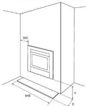
At a minimum, the floor protector must extend 550mm in front of the appliance fascia. It should continue beneath the ZCC to a minimum overall depth of 1185mm and must be 945mm wide.
Elevated installation
Masonry
In some instances is may be desirable, or required that the Eureka Pearl Insert be installed into an existing fireplace which is raised above a combustible floor. In this situation, the minimum required hearth can be reduced to the corresponding elevated height dimensions mentioned in Table 1.
Scenario - The appliance is to be installed into an existing brick masonry fireplace which is situated 100mm above a combustible floor, at this height the minimum required hearth depth is 450mm in front of the appliance fascia. (refer Table 1.)
ZCC
In the instance the ZCC is raised in a combustible enclosure, the structure used to support the appliance at its desired height must be constructed out of non-combutable material (steel tube, c-section, Hebel etc.), and must be able to withstand the combined weight of the Eureka Pearl Insert, the ZCC and the flue system (in excess of 250kg combined).
When the appliance is raised 175mm or more above a combustible floor, a 300mm non-combustible hearth or floor protector is always required as per AS/NZS 2918:2001.
Elevated installation details (dimensions in mm)
| Minimum ApplianceHearth Depth raised by | |
| X | Y |
| 550 | 0 |
| 525 | 25 |
| 500 | 50 |
| 475 | 70 |
| 450 | 90 |
| 425 | 105 |
| 400 | 120 |
| 375 | 135 |
| 350 | 150 |
| 325 | 160 |
| 300 | 175 |
| 300 | >175 |
Table 1. Appliance height vs hearth requirements
ZCC installation elevated example - Figure 3
Pearl Insert 6
Installation (Continued)
ZCC Installation notes
The Eureka Pearl has been factory fitted and attached inside the ZCC. Depending on your desired installation type, whether it be at ground level, or elevated for a mid-wall installation, the following sequence of installation steps may need to be adjusted to suit.
- Select the position that you wish to install your Eureka Pearl Insert ZCC, carefully allowing for flue clearances of 305mm in the roof cavity (the outer flue being 255mm requires a 25mm clearance on either side to combustibles, making overall clearance of 305mm), and allowing for sufficient clearances for combustibles where rear and side walls may play a role in the installation process.
- Ensure there is access to a power supply inside the enclosure for connecting the fan in the heater. In some instances an extension cord maybe required to reach a power supply. Please keep in mind that the fan will need to be removed for cleaning, and access to the power supply should be made relatively easy.
- Remove door (open door handle and swing door open to roughly 45deg and lift off hinge), remove cast iron liners and baffle system from inside the firebox to reduce overall weight of unit.
- Using a 5mm allen key, remove x4 M8 cap screws which attach the fascia to the firebox. Carefully remove the fascia and place to the side. Removing the fascia allows the ZCC to be mounted flush with the front of the enclosure face for a flush fascia finish. - If installing at ground level onto a combustible floor surface, place required floor protector under the desired position of the ZCC than carefully lift the ZCC into position.
- Fit flue system to upstands and appliance. Install through roof as per flue manufacturer's instructions, and terminate at the required height above the roof line, fit cowl. Note: the base of the active flue will need to be trimmed and sealed with fire cement. - Build your frame around the ZCC maintaining the clearances listed previously.
- Enclose the front of the frame with minimum 9mm non-combustible cement sheet, villaboard, bellis board, etc. - Enclose the sides of the frame with plaster, timber, MDF, etc.
• Install the mantle if required as per mantle clearances on page 6.
Note: If mantle is made out of combustible material, the Eureka Pearl must have it's hot air deflector attached to the fascia. • Re-attach removable fascia & door.
Pearl Insert 11
Maintaining & Servicing your Eureka
Cleaning the glass
Generally the only time you will possibly need to clean your glass is after a long overnight burn. If you find that you have a wet sticky black film on your glass (creosote), it is better to burn the heater as normal for one load of wood. When the wood has burnt down to a hot bed of embers, open the door and leave it wide open until the glass cools sufficiently to be wiped with a clamp cloth. This should clean all the white smoky film off the glass. Creosote on the glass is normally a sign that you have tried to get too long an overnight burn or you have burnt excessively wet or green wood. If the film on the glass won't come off with a wet cloth, you can use wet ash from the ash bed as a cleaner or commercial products such as Crystal Clear, Johnson Foam Clean or Windex.
To maintain an efficient and safe use of your Eureka Pearl, you may need to adjust the door hinge and catch to ensure the door closes safely and correctly over the duration of its life.
Adjusting door catch
- Open door to gain access to catch.
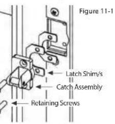
• Using a 3mm Allen key, remove the two catch retaining screws and set aside.
• To tighten the latch, remove one shim. To loosen the latch, fit an additional shim.
• Additional shims are provided in the user manual packaging. Refer to figure 11-1.
- Once the desired setting has been achieved, re-fit the catch assembly using the two retaining screws.
- Note that if an adequate seal cannot be achieved through the removal of one shim, a replacement door rope may be required.
The door hinge defines the door alignment to the heater and the door catch, as well as determining the amount of pressure applied to the main door rope at the hinge side of the door.
To align door:
- Slightly loosen 3 x M8 Bolts securing the hinge to the heater. The upper bolts should be loosened 1-1+1/2 turns, while the lower bolt should only be loosened 1/2 a turn.
- Align door horizontally by pivoting the door about the lower bolt. Note that there is no provision for lateral adjustment of the door hinge position.
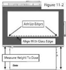
- Check the alignment of the door by measuring vertically from the underside of the door at each outer edge, to the base of the unit, as per figure 11-2. This measurement should be taken with the hinge bolts tightened and with the door hanging under its own weight.
To adjust hinge shims:
- Open door and lift free of hinge, and place on a soft flat surface while servicing the hinge.
- Remove the door hinge and fasteners as shown in figure 13.
- Remove x1 hinge shim plate in order to tighten the seal of the door rope. The maximum number of shims permitted behind the hinge is 2, fitted as standard.
- Fit door and re-align door to catch and firebox before fully tightening M8 bolts.
Adjusting door handle
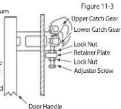
- The door handle position can be adjusted to align the handle with the door glass, when the handle is in the closed position.
- Adjustment is carried out by winding the adjuster screw in or out, in order to change the rest stop position of the handle. This should be done with the door open and the handle resting in the closed position.
- To adjust the position of the screw, first release the lock nuts, then use a Phillip's head screw driver to turn the adjuster screw either in or out depending on the adjustment required.
- Once the desired adjustment position has been achieved, the lock nut should be re-tightened against the retaining plate. Refer to figure 11.3.
Pearl Insert 10
Operating your Eureka (Continued)
- Initial Startup (cold)
Leave fan off until the heater is hot and has established a coal bed - approximately 20 minutes after fuel is lit.
• Medium or High Burn Setting
If the heater is running above medium fire for extended periods of time, fan speeds medium and high are recommended. High is recommended for short bursts where a quick temperature rise is desired in conjunction with a high fire setting.
• Low Burn Setting
The fan cools off the firebox, robbing the combustion process of
efficiency. If you wish the fan can be left off only when the heater is burning a low fire.
Note: Improper use of fan can result in firebox failure.
The fan should be cleaned on a regular basis. (Refer Troubleshooting for fan removal and cleaning.)
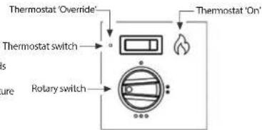
Figure 10
Operation of the Fan
If firebox failure is reported and it is found that the firebox has been abused through improper use of the fan, AF Gason Pty. Ltd. reserve the right to disallow any warranty claims in relation to firebox failure.

The Door
Leaving Door Open
As stated previously, leaving door open 25mm encourages the fire to pick up at a faster rate. Your heater has been tested to ensure that no structural damage can take place if the door is inadvertently left open. However your paint finish can be damaged if the door is left open for a long period with a full firebox of fuel with the fan off. Closely supervise your heater while the door is left open.
Closing the Door
Always ensure that before you close your door there is no wood protruding beyond the front of the firebox opening. Do not use the door glass as a 'battering ram' to push the wood back into the firebox. Damage to the glass by such impact is not covered by your warranty.
Maintaining & Servicing your Eureka
Cleaning your flue (It is recommended that you seek the services of a licensed plumber to carry out flue maintenance). Firstly and carefully remove cast iron plates and baffle system and put to one side. Close the heater door. Obtain a 150mm flue brush from your local Eureka Dealer and proceed up onto the roof. Remove the cowl. Slowly push the brush down the chimney until it stops. Pull the brush back out and repeat the process.
Each time you do this you will notice that the brush will go further down the chimney until it reaches the bottom. The soot and creosote will fall down the chimney and into the firebox. Clean residue from firebox. Replace the baffle plate first, followed by the cast iron liners.
Make sure you do the job well. The cleaner the flue the less chance there will be of the creosote sticking again.
After you replace the cowl, inspect the roof flashing for any damage that may have incurred whilst you were cleaning the flue. Reseal the seal on the roof with roof and gutter silicon if required.
Pearl Insert 7
Installation (Continued)
Baffle System

If the baffle system is damaged, burnt out, discarded or not installed as per these instructions, high flue temperatures, losses in combustion efficiency and excess smoking can occur.
To operate this appliance as it is intended, and to ensure product longevity is achieved, ensure the baffle is installed as per these instructions.
If firebox, flue failure or excess damage to the appliance or its surroundings is reported due to incorrect installation or operation of the Insulated Baffle System, AF Gason Pty. Ltd. reserve the right to disallow any warranty or claims in relation to the abovementioned.
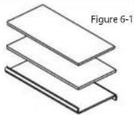
The Eureka Pearl's baffle system comprises of three components:
• 8mm Steel Plate
• 13mm DuraBlanket
• 12mm Silica board
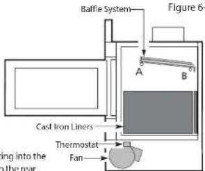
When removing the baffle system to clean the flue, the baffle system must be inspected and replaced in the configuration as shown in Figure 5. If the systems components are compromised in anyway it is important components are replaced.
Fitting the insulated Baffle System
- Feed the baffle plate through the door opening with front edge fold facing up. Feed plate all the way to the rear of the firebox.
- Lift front of baffle over Pin A and slide towards the front of heater.
- Lift the rear so that the baffle is horizontal and move it towards the rear of the firebox.
- Lower over Pin B.
- Ensure baffle is sitting on Pins A and B.
Placement of Cast Iron Liners into firebox
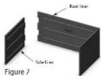
The rear cast iron liner is to be positioned to the rear with rib and logos facing into the firebox. Side cast liners are to be positioned on each side and interlock into the rear cast liner. Refer Figure 6 for orientation.
Final inspection prior to use
- Ensure the baffle system is firmly located and in the correct orientation
- Ensure cast iron liners - side and back - are positioned correctly.
- Check fan cord has not been damaged during transit.
- Plug in fan cord and ensure cord does not touch heater surface.
- Switch thermostat switch to 'Override' and select one of three speeds to ensure fan is operational.
- Check door seals are in place and fitting correctly.
Pearl Insert
8
Installation (Continued) Operating your Eureka
Flue and chimney requirements
The flue pipe shall extend not less than 4.6m above the top of the floor protector. Note: Installation must be carried out by a licensed installer in accordance with AS/NZS 2918:2001.
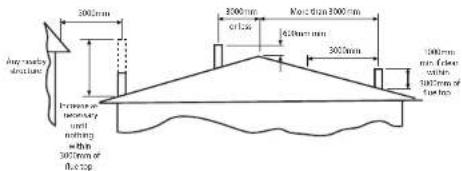
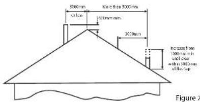
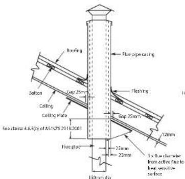
Example of slaped ceiling penetration
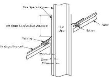
Example of root penetration
Figure 8
Pearl Insert 9

WARNING
Read these instructions
DO NOT ATTEMPT TO OPERATE THIS APPLIANCE WITHOUT READING AND UNDERSTANDING THESE OPERATING INSTRUCTIONS THOROUGHLY. FAILURE TO OPERATE THIS APPLIANCE PROPERLY MAY CAUSE UNDUE DAMAGE TO THE APPLIANCE OR RESULT IN A FLUE FIRE.
Starting your fire
Place a firelighter or paper in the bottom of the firebox and place a large amount of small kindling on top. Ignite the paper or the firefighter. Set the air control to high and leave the main door open approximately 25mm. When the kindling is burning, place about four pieces of small wood on top of the burning kindling. Once the wood is alight, close the main door. After approximately 20 minutes, turn the air control down to medium. For fan operation refer page 10.
On the initial fire up you may detect smoke coming from the paint finish and from any oils that may be on the steel on the outside of the firebox. This is normal. It is suggested to well ventilate your home on the initial fire up. Please refer to our section 'Paint Curing and Care' on page 2.
The glass door
Always operate your heater with the door closed and locked. The only time you can leave the door open is on initial lighting, or when reloading the heater.
Care of your glass
If you are burning good dry wood, you will have very little discolouration of your glass in normal burning cycle. If you aim for an eight to ten hour overnight burn, you should not get much discolouration. You can control this by adjusting the air control, moving from the left and slowly creeping the control to the right. After a number of days you will find the right position to suit your requirements and the fuel that you are using.
Daily operations
When you get up in the morning, open up the air control of the heater to high position to start the embers glowing. Place three or four pieces of wood on top of the embers and leave the door open 25mm. Once the fuel starts to flame close the door. Depending on your daily heating requirements, operate the fan as per fan operation instructions on page 10. For best results it is best to burn 410mm long wood and load your wood straight into the firebox front to rear. This will give optimum efficiency and recoverable heat, and minimise creosote formation and smoke emissions.
Overnight burn
Approximately 30 minutes before turning the heater down for the overnight burn it is recommended to load the heater with fuel. Leave the air control in the medium to high position. Let the heater run for about 30 minutes. This will reduce the moisture content in the fuel before shut down. (This will help reduce the creosote formation in the firebox and flue.) Set the air control to the setting you have found best for your requirements. Turn the fan off or to the thermostat control position and retire. The aim when overnight burning is to have only a few hot embers left in the bottom of the firebox in the morning, not huge lumps of wood.
Fan operation
Your Eureka Pearl Insert is equipped with a temperature-sensitive thermostat switch located within the heater's fascia beneath the firebox, which when selected will turn the fan on and off depending on the temperature of the firebox. To use the thermostat, select the thermostat 'On' position via the thermostat switch, and select the desired fan speed you wish to use (low, medium or high).
If the fan is not coming on at the desired time, flip the switch into the Override position and operate the 3 speed fan as described on page 10.

- WARRANTY
- Operation & Installation Instructions
- WARNING
- Read and follow these instructions carefully before installing and using this appliance.
- PLEASE COMPLETE:
- Firewood
- Getting the most out of your firewood
- Thermal efficiency
- The combustion process of burning wood
- Troubleshooting
- - Noisy Fan
- • Fan not working
- • Air control jamming
- • No overnight burn
- • Excessive ash build up
- - Excessive smoking - smoke entering the room maybe caused by:
- Installation
- Installation permit
- Installation into existing or masonry fireplace
- Installation Into Zero Clearance Cabinet - ZCC
- Installation (Continued)
- Clearance to combustibles & Zero Clearance Cabinet (ZCC) Installation
- Cladding
- Maintaining & Servicing your Eureka (Continued)
- Replacing your glass
- Fitting a new door seal
- Hearth & floor requirement
- Elevated installation
- Masonry
- ZCC
- ZCC Installation notes
- Maintaining & Servicing your Eureka
- Cleaning the glass
- Adjusting door catch
- Adjusting door handle
- Operating your Eureka (Continued)
- Leaving Door Open
- Closing the Door
- Baffle System
- Fitting the insulated Baffle System
- Placement of Cast Iron Liners into firebox
- Final inspection prior to use
- Installation (Continued) Operating your Eureka
- Flue and chimney requirements
- Starting your fire
- The glass door
- Care of your glass
- Daily operations
- Overnight burn
- Fan operation
Brand : EUREKA
Model : Pearl Insert
Category : Heating