
3RW5227-1AC15 - Wall socket SIEMENS - Free user manual and instructions
Find the device manual for free 3RW5227-1AC15 SIEMENS in PDF.

| Product Type | Wall Socket |
| Brand | Siemens |
| Model | 3RW5227-1AC15 |
| Rated Voltage | 250 V AC |
| Rated Current | 16 A |
| Number of Sockets | 1 |
| Material | Thermoplastic, high impact resistance |
| Color | White |
| Dimensions (H x W x D) | 86 mm x 86 mm x 38 mm |
| Weight | 0.12 kg |
| Protection Class | IP20 (indoor use) |
| Child Protection | Shutter system to prevent insertion of objects |
| Standards Compliance | IEC 60884-1, VDE 0620 |
| Installation Type | Flush mounting (requires mounting box) |
| Terminal Connection | Screw terminals for up to 2.5 mm² wires |
| Operating Temperature | -5 °C to +40 °C |
| Flame Resistance | UL94 V-0 rated |
| Warranty | 2 years |
| Maintenance | Wipe with a dry cloth; no solvents |
| Repairability | Replaceable front cover available as spare part |
Frequently Asked Questions - 3RW5227-1AC15 SIEMENS
User questions about 3RW5227-1AC15 SIEMENS
0 question about this device. Answer the ones you know or ask your own.
Ask a new question about this device
Download the instructions for your Wall socket in PDF format for free! Find your manual 3RW5227-1AC15 - SIEMENS and take your electronic device back in hand. On this page are published all the documents necessary for the use of your device. 3RW5227-1AC15 by SIEMENS.
USER MANUAL 3RW5227-1AC15 SIEMENS
SIRIUS soft starter 200-600 V 93 A, 110-250 V AC Screw terminals Analog output
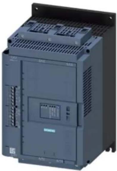
natural_image
Industrial control unit with visible I/O ports and ventilation grilles (no text or symbols)| Product brand name SIRIUS | |
| Product category Hybrid switching devices | |
| Product designation Soft starter | |
| Product type designation 3RW52 | |
| Manufacturer's article number | |
| • of HMI module usable | 3RW5980-0HS00 |
| • of HMI-Modul high-feature usable | 3RW5980-0HF00 |
| • of communication module PROFINET standard usable | 3RW5980-0CS00 |
| • of communication module PROFIBUS usable | 3RW5980-0CP00 |
| • of communication module Modbus TCP usable | 3RW5980-0CT00 |
| • of communication module Modbus RTU usable | 3RW5980-0CR00 |
| • of communication module Ethernet/IP | 3RW5980-0CE00 |
| • of circuit breaker usable at 400 V | 3VA2216-7MN32-0AA0; Type of coordination 1, Iq = 15 kA, CLASS 10 |
| • of circuit breaker usable at 500 V | 3VA2216-7MN32-0AA0; Type of coordination 1, Iq = 10 kA, CLASS 10 |
| • of circuit breaker usable at 400 V at inside-delta circuit | 3VA2220-7MN32-0AA0; Type of coordination 1, Iq = 15 kA, CLASS 10 |
| • of circuit breaker usable at 500 V at inside-delta circuit | 3VA2220-7MN32-0AA0; Type of coordination 1, Iq = 10 kA, CLASS 10 |
• of the gG fuse usable up to 690 V
- of the gG fuse usable at inside-delta circuit up to 500 V
- of full range R fuse link for semiconductor protection usable up to 690 V
- of back-up R fuse link for semiconductor protection usable up to 690 V
3NA3136-6; Type of coordination 1, Iq = 65 kA
3NA3136-6; Type of coordination 1, Iq = 65 kA
3NE1224-0; Type of coordination 2, Iq = 65 kA
3NE4124; Type of coordination 2, Iq = 65 kA
| General technical data | |
| Starting voltage [%] 30 ... 100 % | |
| Stopping voltage [%] 50 ... 50 % | |
| Start-up ramp time of soft starter 0 ... 20 s | |
| Current limiting value [%] adjustable 130 ... 700 % | |
| Certificate of suitability | |
| • CE marking | Yes |
| • UL approval | Yes |
| • CSA-approval | Yes |
| Product component | |
| • is supported HMI-Standard | Yes |
| • is supported HMI-High Feature | Yes |
| Product feature integrated bypass contact system Yes | |
| Number of controlled phases 3 | |
| Trip class CLASS 10A (default) / 10E / 20E; acc. to IEC | 60947-4-2 |
| Insulation voltage | |
| • rated value | 600 V |
| Degree of pollution 3, acc. to IEC 60947-4-2 | |
| Impulse voltage rated value 6 kV | |
| Blocking voltage of the thyristor maximum 1 800 V | |
| Service factor 1 | |
| Surge voltage resistance rated value 6 kV | |
| maximum permissible voltage for safe isolation | |
| • between main and auxiliary circuit | 600 V |
| Protection class IP IP00 | |
| Usage category acc. to IEC 60947-4-2 AC 53a | |
| Shock resistance 15 g / 11 ms, from 12 g / 11 ms with potential contact lifting | |
| Vibration resistance 15 mm to 6 Hz; 2g to 500 Hz | |
| Reference code acc. to DIN EN 81346-2 | Q |
| Product function | |
| • ramp-up (soft starting) | Yes |
| • ramp-down (soft stop) | Yes |
| • Soft Torque | Yes |
| • Adjustable current limitation | Yes |
| • pump ramp down | Yes |
| Intrinsic device protection | Yes |
| motor overload protection | Yes; Electronic motor overload protection |
| Evaluation of thermistor motor protection | No |
| Inside-delta circuit | Yes |
| Auto-reset | Yes |
| Manual RESET | Yes |
| remote reset | Yes; By turning off the control supply voltage |
| communication function | Yes |
| Operating measured value display | Yes |
| error logbook | Yes |
| via software parameterizable | No |
| via software configurable | Yes |
| PROFlenergy | Yes; in connection with the PROFINET Standard communication module |
| firmware update | Yes |
| removable terminal for control circuit | Yes |
| torque control | No |
| analog output | Yes; 4 ... 20 mA (default) / 0 ... 10 V (parameterizable with High Feature HMI) |
Power Electronics
| Operating current | |
| • at 40 °C rated value | 93 A |
| • at 50 °C rated value | 82.5 A |
| • at 60 °C rated value | 75.5 A |
| Operating current at inside-delta circuit | |
| • at 40 °C rated value | 161 A |
| • at 50 °C rated value | 143 A |
| • at 60 °C rated value | 131 A |
| Operating voltage | |
| • rated value | 200 ... 600 V |
| • at inside-delta circuit rated value | 200 ... 600 V |
| Relative negative tolerance of the operating voltage -15 % | |
| Relative positive tolerance of the operating voltage 10 % | |
| Relative negative tolerance of the operating voltage at inside-delta circuit | -15 % |
| Relative positive tolerance of the operating voltage at inside-delta circuit | 10 % |
| Operating power for three-phase motors | |
| • at 230 V at 40 °C rated value | 22 kW |
| • at 230 V at inside-delta circuit at 40 °C rated value | 45 kW |
| • at 400 V at 40 °C rated value | 45 kW |
| at 400 V at inside-delta circuit at 40 °C rated value | 90 kW |
| at 500 V at 40 °C rated value | 55 kW |
| at 500 V at inside-delta circuit at 40 °C rated value | 110 kW |
| Operating frequency 1 rated value 50 Hz | |
| Operating frequency 2 rated value 60 Hz | |
| Relative negative tolerance of the operating frequency | -10 % |
| Relative positive tolerance of the operating frequency 10 % | |
| Adjustable motor current | |
| at rotary encoding switch on switch position 1 | 40.5 A |
| at rotary encoding switch on switch position 3 | 47.5 A |
| at rotary encoding switch on switch position 4 | 51 A |
| at rotary encoding switch on switch position 5 | 54.5 A |
| at rotary encoding switch on switch position 6 | 58 A |
| at rotary encoding switch on switch position 7 | 61.5 A |
| at rotary encoding switch on switch position 8 | 65 A |
| at rotary encoding switch on switch position 9 | 68.5 A |
| at rotary encoding switch on switch position 10 | 72 A |
| at rotary encoding switch on switch position 11 | 75.5 A |
| at rotary encoding switch on switch position 12 | 79 A |
| at rotary encoding switch on switch position 13 | 82.5 A |
| at rotary encoding switch on switch position 14 | 86 A |
| at rotary encoding switch on switch position 15 | 89.5 A |
| at rotary encoding switch on switch position 16 | 93 A |
| minimum | 40.5 A |
| at inside-delta circuit minimum | 70.1 A |
| Adjustable motor current for inside-delta circuit | |
| at rotary encoding switch on switch position 1 | 70.1 A |
| at rotary encoding switch on switch position 2 | 76.2 A |
| at rotary encoding switch on switch position 3 | 82.3 A |
| at rotary encoding switch on switch position 4 | 88.3 A |
| at rotary encoding switch on switch position 5 | 94.4 A |
| at rotary encoding switch on switch position 6 | 100 A |
| at rotary encoding switch on switch position 7 | 107 A |
| at rotary encoding switch on switch position 8 | 113 A |
| at rotary encoding switch on switch position 9 | 119 A |
| at rotary encoding switch on switch position 10 | 125 A |
| at rotary encoding switch on switch position 11 | 131 A |
| at rotary encoding switch on switch position 12 | 137 A |
| at rotary encoding switch on switch position 13 | 143 A |
| • at rotary encoding switch on switch position 14 | 149 A |
| • at rotary encoding switch on switch position 15 | 155 A |
| • at rotary encoding switch on switch position 16 | 161 A |
| Minimum load [%] 15 %; Relative to smallest settable le | |
| Power loss [W] for rated value of the current at AC | |
| • at 40 °C to power-up | 40 W |
| • at 50 °C to power-up | 37 W |
| • at 60 °C to power-up | 35 W |
| Power loss [W] at AC at AC | |
| • at 60 °C during startup | 959 W |
| • at 50 °C during startup | 1 077 W |
Control circuit/ Control
| Type of voltage of the control supply voltage AC | |
| Control supply voltage at AC | |
| • at 50 Hz | 110 ... 250 V |
| • at 60 Hz | 110 ... 250 V |
| Relative negative tolerance of the control supply voltage at AC at 50 Hz | -15 % |
| Relative positive tolerance of the control supply voltage at AC at 50 Hz | 10 % |
| Relative negative tolerance of the control supply voltage at AC at 60 Hz | -15 % |
| Relative positive tolerance of the control supply voltage at AC at 60 Hz | 10 % |
| Control supply voltage frequency 50 ... 60 Hz | |
| Relative negative tolerance of the control supply voltage frequency | -10 % |
| Relative positive tolerance of the control supply voltage frequency | 10 % |
| Control supply current in standby mode rated value 30 mA | |
| Holding current in the by-pass mode operating rated value | 75 mA |
| Starting current at close of by-pass contact maximum 2.5 A | |
| Inrush current peak at connect of control supply voltage maximum | 12.2 A |
| Duration of inrush current peak at connect of control supply voltage | 2.2 ms |
| Design of the overvoltage protection Varistor | |
| Design of short-circuit protection for control circuit | 4 A gG fuse (Icu=1 kA), 6 A quick-acting fuse (Icu=1 kA), C1 miniature circuit breaker (Icu= 600 A), C6 miniature circuit breaker (Icu= 300 A); Is not part of scope of supply |
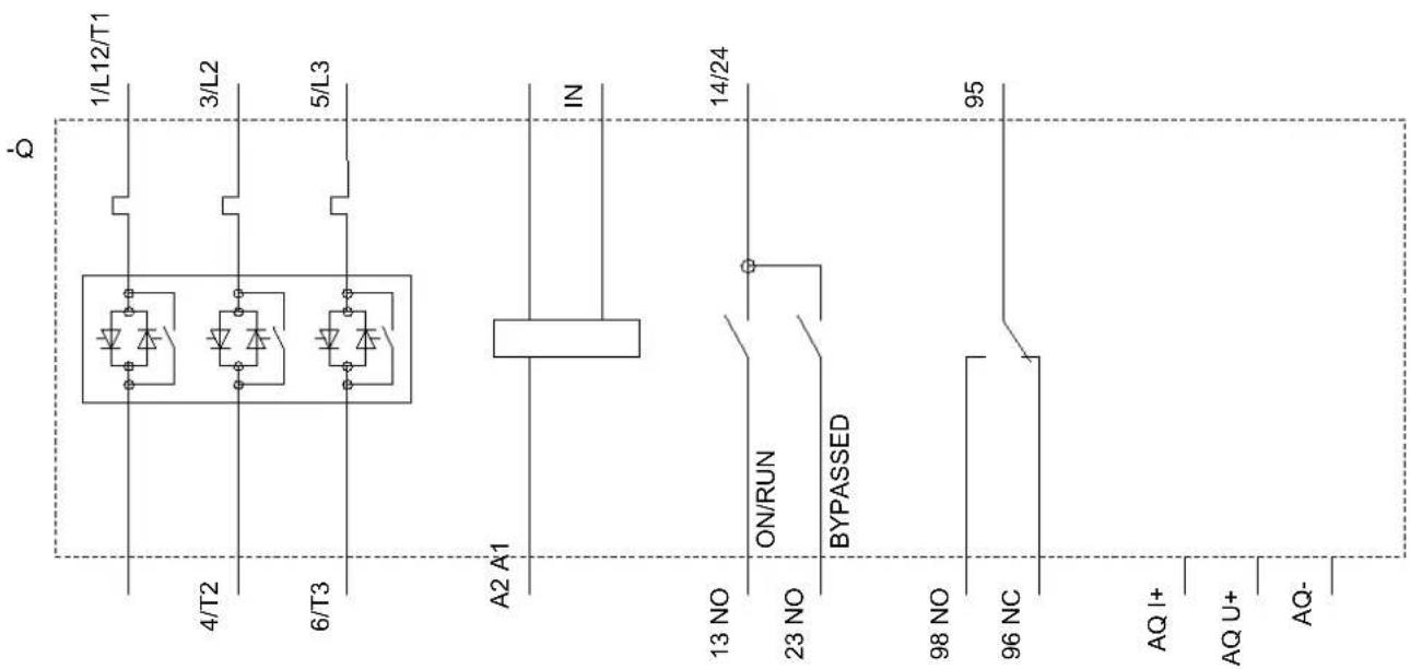
Inputs/ Outputs
| Number of digital inputs 1 | |
| Number of inputs for thermistor connection 0 | |
| Number of digital outputs 3 | |
| • not parameterizable | 2 |
| Digital output version 2 normally-open contacts (NO) / 1 | changeover contact (CO) |
| Number of analog outputs 1 | |
| Switching capacity current of the relay outputs | |
| • at AC-15 at 250 V rated value | 3 A |
| • at DC-13 at 24 V rated value | 1 A |
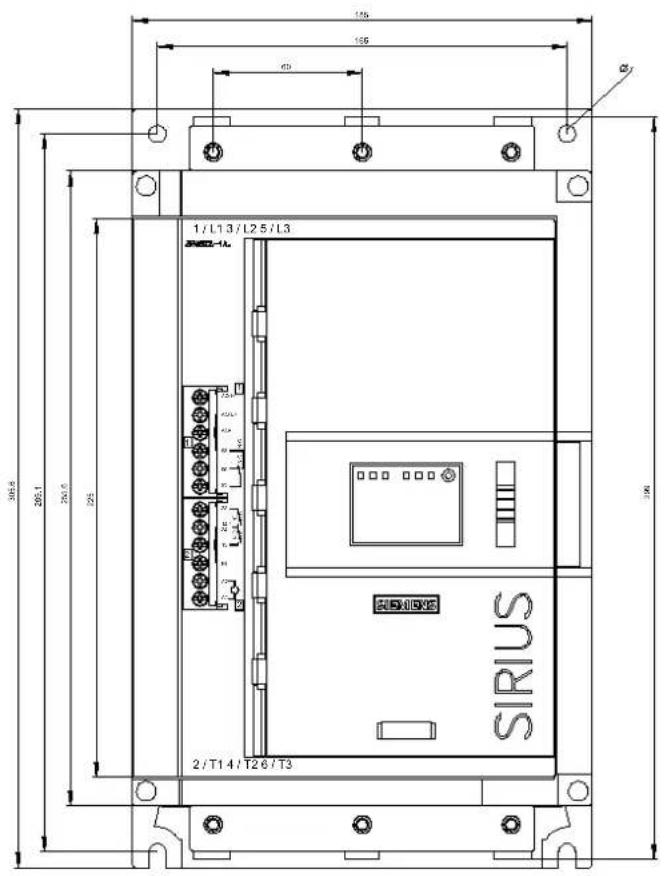
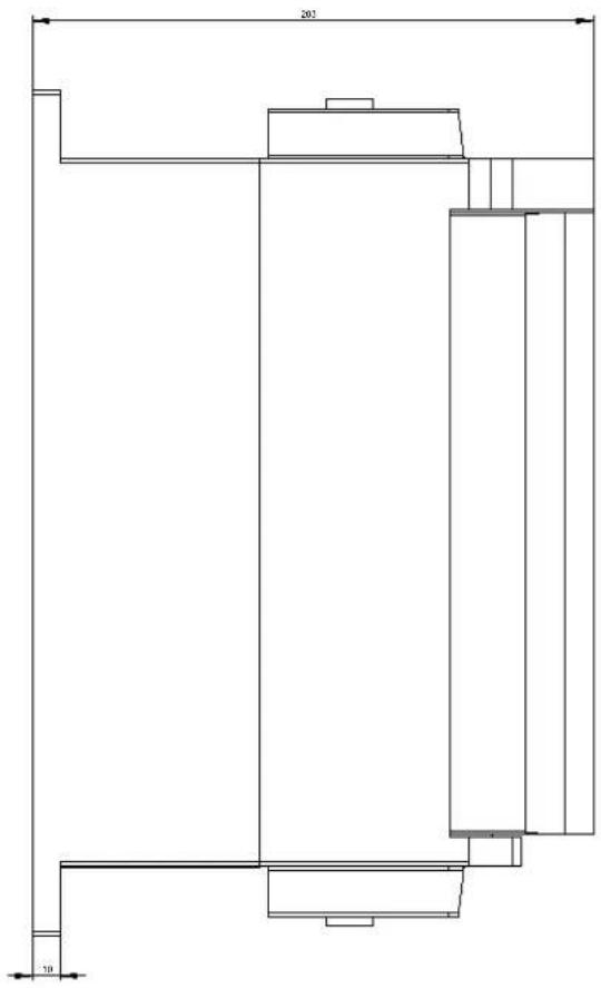
Installation/ mounting/ dimensions
| Mounting position with vertical mounting surface +/-90° rotatable, with vertical mounting surface +/- 22.5° tiltable to the front and back | |
| Mounting type screw fixing | |
| Height 306 mm | |
| Width 185 mm | |
| Depth 203 mm | |
| Required spacing with side-by-side mounting | |
| • forwards | 10 mm |
| • Backwards | 0 mm |
| • upwards | 100 mm |
| • downwards | 75 mm |
| • at the side | 5 mm |
| Installation altitude at height above sea level maximum | 5 000 m; Derating as of 1000 m, see catalog |
| Weight without packaging 6.9 kg | |
Connections/ Terminals
| Type of electrical connection | |
| • for main current circuit | box terminal |
| • for control circuit | screw-type terminals |
| Type of connectable conductor cross-sections | |
| • for main contacts for box terminal using the front clamping point solid | 1x (2.5 ... 16 mm ^2 ) |
| • for main contacts for box terminal using the front clamping point finely stranded with core end processing | 1x (2.5 ... 50 mm ^2 ) |
| • for main contacts for box terminal using the front clamping point stranded | 1x (10 ... 70 mm ^2 ) |
| • at AWG conductors for main contacts for box terminal using the front clamping point | 1x (10 ... 2/0) |
| • for main contacts for box terminal using the back clamping point solid | 1x (2.5 ... 16 mm ^2 ) |
| • at AWG conductors for main contacts for box terminal using the back clamping point | 1x (10 ... 2/0) |
| • for main contacts for box terminal using both clamping points solid | 2x (2.5 ... 16 mm ^2 ) |
| for main contacts for box terminal using both clamping points finely stranded with core end processingfor main contacts for box terminal using both clamping points strandedfor main contacts for box terminal using the back clamping point finely stranded with core end processingfor main contacts for box terminal using the back clamping point stranded | 2x (2.5 ... 35 mm ^2 )2x (6 ... 16 mm ^2 ), 2x (10 ... 50 mm ^2 )1x (2.5 ... 50 mm ^2 )1x (10 ... 70 mm ^2 ) |
| Type of connectable conductor cross-sectionsfor control circuit solidfor control circuit finely stranded with core end processingat AWG conductors for control circuit solid | 1x (0.5 ... 4.0 mm ^2 ), 2x (0.5 ... 2.5 mm ^2 )1x (0.5 ... 2.5 mm ^2 ), 2x (0.5 ... 1.5 mm ^2 )1x (20 ... 12), 2x (20 ... 14) |
| Wire lengthbetween soft starter and motor maximumat the digital inputs at AC maximum | 800 m100 m |
Ambient conditions
| Ambient temperature | |
| • during operation | -25 ... +60 °C; Please observe derating at temperatures of 40 °C or above |
| • during storage and transport | -40 ... +80 °C |
| Environmental category | |
| • during operation acc. to IEC 60721 | 3K6 (no ice formation, only occasional condensation), 3C3 (no salt mist), 3S2 (sand must not get into the devices), 3M6 |
| • during storage acc. to IEC 60721 | 1K6 (only occasional condensation), 1C2 (no salt mist), 1S2 (sand must not get inside the devices), 1M4 |
| • during transport acc. to IEC 60721 | 2K2, 2C1, 2S1, 2M2 (max. fall height 0.3 m) |
EMC emitted interference acc. to IEC 60947-4-2: Class A
Communication/ Protocol
| Communication module is supported | |
| • PROFINET standard | Yes |
| • EtherNet/IP | Yes |
| • Modbus RTU | Yes |
| • Modbus TCP | Yes |
| • PROFIBUS | Yes |
UL/CSA ratings
| Manufacturer's article number | |
| • of circuit breaker | |
| — usable for Standard Faults at 460/480 V according to UL | Iq = 10 kA |
— usable for High Faults at 460/480 V according to UL
— usable for Standard Faults at 460/480 V at inside-delta circuit according to UL
— usable for High Faults at 460/480 V at inside-delta circuit according to UL
— usable for Standard Faults at 575/600 V according to UL
— usable for Standard Faults at 575/600 V at inside-delta circuit according to UL
- of the fuse
— usable for Standard Faults up to 575/600 V according to UL
— usable for High Faults up to 575/600 V according to UL
— usable for Standard Faults at inside-delta circuit up to 575/600 V according to UL
— usable for High Faults at inside-delta circuit up to 575/600 V according to UL
Operating power [hp] for three-phase motors
• at 200/208 V at 50 °C rated value
• at 220/230 V at 50 °C rated value
• at 460/480 V at 50 °C rated value
• at 575/600 V at 50 °C rated value
- at 200/208 V at inside-delta circuit at 50 °C rated value
- at 220/230 V at inside-delta circuit at 50 °C rated value
- at 460/480 V at inside-delta circuit at 50 °C rated value
- at 575/600 V at inside-delta circuit at 50 °C rated value
Contact rating of auxiliary contacts according to UL R300-B300
Electromagnetic compatibility in accordance with IEC 60947-4-2
Iq max = 65 kA
Iq = 10 kA
Iq max = 65 kA
Iq = 10 kA
Iq = 10 kA
Type: Class RK5 / K5, max. 300 A; Iq = 10 kA
Type: Class J / L, max. 250 A; Iq = 100 kA
Type: Class RK5 / K5, max. 300 A; Iq = 10 kA
Type: Class J / L, max. 250 A; Iq = 100 kA
25 hp
30 hp
60 hp
75 hp
40 hp
50 hp
100 hp
125 hp
Certificates/ approvals
| General Product Approval EMC Declaration of | Conformity |

CCC

CSA

UL


RCM

EG-Konf.
| Declaration of Conformity | Test Certificates | Marine / Shipping other |
Miscellaneous Type Test Certificates/Test Report

ABS

LRS

PRS
Confirmation
Further information
Information- and Downloadcenter (Catalogs, Brochures,...)
www.siemens.com/sirius/catalogs
Industry Mall (Online ordering system)
https://mall.industry.siemens.com/mall/en/en/Catalog/product?mlfb=3RW5227-1AC15
Cax online generator
http://support.automation.siemens.com/WW/CAXorder/default.aspx?lang=en&mlfb=3RW5227-1AC15
Service&Support (Manuals, Certificates, Characteristics, FAQs,...)
https://support.industry.siemens.com/cs/ww/en/ps/3RW5227-1AC15
Image database (product images, 2D dimension drawings, 3D models, device circuit diagrams, EPLAN macros, ...)
http://www.automation.siemens.com/bilddb/cax_de.aspx?mlfb=3RW5227-1AC15&lang=en
Characteristic: Tripping characteristics, I²t, Let-through current
https://support.industry.siemens.com/cs/ww/en/ps/3RW5227-1AC15/char
Characteristic: Installation altitude
http://www.automation.siemens.com/bilddb/index.aspx?view=Search&mlfb=3RW5227-1AC15&objecttype=14&gridview=view1
last modified:
09/18/2019