HSW-ES - Sliding door Dormakaba - Free user manual and instructions
Find the device manual for free HSW-ES Dormakaba in PDF.


| Product Type | Sliding Glass Wall System (HSW-ES) |
| Brand | dormakaba |
| Model | HSW-ES |
| Maximum Door Leaf Weight | Pivoting end panel: ≤330 lbs (≤150 kg); Sliding panel: ≤330 lbs (≤150 kg); Double-action sliding panel: ≤264 lbs (≤120 kg); Fixed panel: ≤330 lbs (≤150 kg) |
| Glass Type Required | Fully tempered glass (ASTM C 1036 / C 1048); monolithic or laminated; no self-cleaning coating |
| Mounting Type | Ceiling mount |
| Operation | Manual slow opening and closing; sliding and pivoting |
| Intended Use | Indoor wet or dry areas only |
| Track Level Tolerance | 1/8" (3 mm) over 10' (3048 mm), non-cumulative |
| Floor Level Tolerance | ±1/8" (3 mm) over 10' (3048 mm), non-cumulative |
| Minimum Gap Bottom of Door to Floor | 3/8" (10 mm) |
| Tools Required for Installation | Rubber mallet, pliers, plumb bob, wrenches (8/15/17 mm), drill, hex keys (3/5/6 mm), hole saws (25/40 mm), torque wrench, screwdrivers, tape measure, laser level |
| Maintenance | Clean with damp cloth; use silicone- and oil-free cleaners; check regularly for smooth operation |
| Safety Instructions | Two-person installation; wear protective clothing; use tempered glass; never clamp hardware directly to glass; avoid excessive force |
| Spare Parts | Use only original dormakaba parts |
| Repair | Immediately replace damaged parts; inspect by qualified personnel for high-traffic systems |
| Disposal | In accordance with local, state, and national regulations |
Frequently Asked Questions - HSW-ES Dormakaba
User questions about HSW-ES Dormakaba
0 question about this device. Answer the ones you know or ask your own.
Ask a new question about this device
Download the instructions for your Sliding door in PDF format for free! Find your manual HSW-ES - Dormakaba and take your electronic device back in hand. On this page are published all the documents necessary for the use of your device. HSW-ES by Dormakaba.
USER MANUAL HSW-ES Dormakaba
natural_image
Technical line drawing of a structural frame with diagonal bracing and vertical supports (no text or symbols)HSW-ES Sliding Glass Walls
Easy Safe
Installation instructions
940001 - 05-2019
| EN |
Table of contents
1 Technical specifications 3
1.1 Overview 3
1.1.1 General information 3
1.1.2 Intended use 3
1.1.3 Glass requirements/fittings/mounting 3
1.1.4 Requirements for glass panel 3
1.1.5 Safety instructions 3
1.1.6 Symbols used - Safety/Installation 3
1.1.7 Maintenance, care, repair 3
1.1.8 Disposal
1.2 Specification - technical data 4
1.3 Tempered laminate glass (TLG) and adhesive specifications 4
1.4 Tools required 4
1.5 Installation options/Overall top of door components 5
1.6 Installation options/Bottom of door components 6
1.7 Installation options/Bottom of door components (continued) 7
2 Installation instructions - Prepare track 8
2.1 Determine the track arrangement 8
2.2 Install single-action pivoting end panel retaining clip 9
2.3 Install door track stop in stacking area 10
2.4 Installing the track 11
2.5 Installing upper pivot block 12
2.6 Install rollers in track 13
2.7 Install revision piece 14
2.8 Prepare the roller pattern in the track 15
3 Installation instructions - DA & SA pivoting end panel 16
3.1 Preparing the DA & SA pivoting end panel (with monolithic glass only) 16
3.2 Preparing the DA & SA pivoting end panel (with tempered laminated glass only) 17
3.3 Preparing the upper pivot block 18
3.4 Install floor pivot or BTS80 closer 19
3.5 Install pivot into end panel carrier profile 20
3.6 Install top cover gasket 21
3.7 Installing top covers 21
3.8 Install DA & SA pivoting end panel into track 22
3.9 Secure end panel in track 23
4 Installation instructions - Sliding panel 24
4.1 Preparing the sliding panel (with monolithic glass only) 24
4.2 Preparing the sliding panel (with tempered laminated glass only) 25
4.3 Install sliding panel onto rollers and adjust door height 26
4.4 Install gasket and top cover 27
5 Installation instructions - Double-action sliding panel with ITS96 28
5.1 Preparing the DA sliding panel (with monolithic glass) 28
5.2 Preparing the DA sliding panel (with tempered laminated glass only) 29
5.3 Installing three piece lock 30
5.4 Prep for installing two piece lock (when required) 31
5.5 Install top cover and carrier profile gaskets 31
5.6 Installing three piece lock (continued) 32
5.7 Install two piece lock (continued) 33
5.8 Installing DA sliding panels onto rollers and adjust door height 34
5.9 Secure three piece lock to track 35
5.10 Secure two piece lock to track 36
5.11 ITS96 closer adjustment 37
5.12 ITS96 hold open (optional) and spring force adjustment 38
6 Installation instructions - Fixed panel door 39
6.1 Preparing the fixed panel door (with monolithic glass only) 39
6.2 Preparing the fixed panel door (with tempered laminated glass only) 40
6.3 Installing the fixed panel holders 41
6.4 Installing the saddle and fixed panel door 42
6.5 Adjusting and securing fixed panel door 43
6.6 Install gasket and top cover 44
7 Installation instructions - Alignment, covers, end caps, miscellaneous 45
7.1 Aligning panels into stacking area 45
7.2 Aligning panels side by side in straight run 46
7.3 Secure carrier profile file connecting inserts and end caps 47
7.4 Drilling for ES locking bolt strike 48
7.5 Secure bottom rail covers and rail lock preparation 49
7.6 Installing the brush 50
7.7 Selecting the proper end cap 51
7.8 Secure the end caps 52
1 Technical specifications
1.1 Overview
These instructions are for installation of HSW-ES Sliding Wall Systems for the following mounting and style versions:
1. Ceiling mount
1.1.1 General information
- dormakaba requires use of tempered laminated or tempered monolithic glass.
- dormakaba glass hardware is not suitable for harsh environment; for example, applications where chemicals (e.g. chlorine) are used such as indoor swimming pools, saunas, or salt-water pools.
- Never move sliding panels faster than walking speed and always stop the door manually before it reaches end position.
- Do not slide doors with excessive force. Ensure proper installation of limiting stop to prevent door from opening too far.
- Do not swing doors with excessive force. Recommended install of limiting stop to prevent door from opening too far.
1.1.2 Intended use
- For sliding doors in wet or dry indoor areas only.
- For manual slow opening and closing only.
1.1.3 Glass requirements/fittings/mounting
- The structural support must be able to bear permanent loads. Track must be level to 1/8'' [3] over 10' [3048] non-cumulative. Maximum deflection ± 1/8'' [ ± 3 ] over 10' [3048] non-cumulative. Finished floor must be level to within ± 1/8'' [ ± 3 ] over 10' [3048] non-cumulative.
- Fasteners must be sufficiently dimensioned for the substructure/wall and weight of the door.
- When adjusting glass components, always stick to the required clearance for the respective hardware. Adjust clearance so glass does not come in contact with any hard surfaces such as glass, metal or concrete.
- Do not use excessive force when installing the glass (avoid over tightening screws.)
1.1.4 Requirements for glass panel
- dormakaba requires use of fully tempered glass, which complies with ASTM C 1036 and ASTM C 1048. Secondary heat soaking processes are recommended but not required. This applies to both tempered monolithic and tempered laminated glass.
- Clamping area must be flat and uncoated (no self-cleaning coating!)
- Never use glass with conchoidal fractures and/or damaged edges.
1.1.5 Safety instructions
• Installation requires two people.
• Always wear protective clothing.
- Only properly qualified and specially trained staff are authorized to mount dormakaba glass hardware.
- Due to crushing hazards and possible injury caused by breakage of glass during mounting, corresponding protective clothing (especially gloves and protective goggles) is required.
- Never clamp metal fitting hardware directly to glass surface.
1.1.6 Symbols used - Safety/Installation

CAUTION
Mounting components must meet the requirements of substructure/wall and door weight. Please read the technical information for fittings.

WARNING
Risk of breaking glass. When installing the door, support the door panel with a block of wood or similar object.

WARNING
Risk of pinching. When sliding the panels ensure hands and body parts are free from between the closing edges.

TIPS AND RECOMMENDATIONS

CLOSING EDGE OF DOOR
1.1.7 Maintenance, care, repair
- Immediately replace damaged parts.
• Always use original dormakaba parts. -
Clean clamping area with alcohol-based standard commercial cleaning agent before mounting the glass hardware.
-
Use a damp cloth for occasional cleaning.
• Always use silicone - and oil-free cleaners (e.g. acetone). - Check glass hardware at regular intervals for proper positioning, smooth operation and correct adjustment.
- High traffic door systems require inspection by properly trained or qualified staff (specialized companies or installation firms.)
1.1.8 Disposal
Disposal in accordance with local, state and national regulations.
1.2 Specification - technical data
| Pivoting end panel | Sliding panel | Double action sliding panel | Fixed panel | ||
| Ceiling mount | Maximum door leaf weight lbs [kg] * ≤ 330 lbs | [≤ 150] | ≤ 330 lbs[≤ 150] | ≤ 264 lbs[≤ 120] | ≤ 330 lbs[≤ 150] |
* Including weight of auxiliary hardware.
1.3 Tempered laminate glass (TLG) and adhesive specifications
| Required parts for laminate glass (not included) | Part Number Quantity Usage recommendation |
| 3M^TM Scotch-Weld ^TM Urethane Adhesive, DP 605 NS | 934.800 1 tube 1 tube per 4 roller carriers |
| 3M^TM Scotch-Weld ^TM EPXTM Plus II Applicator with 1:1 Plunger ^1 | 934.801 1 applicator 1:1 plunger with 934.800 adhesive |
| 3M^TM Scotch-Weld ^TM EPXTM Plus II Mixing Square Nozzle, 5.3mm ^2 | 934.805 Pk of 4 4 nozzles per 1 tube of adhesive |
| Handling time frame Function Time | |
| Working life (time between application and clamping of carrier)5 minutes @ 75°F | |
| Handling strength 20 minutes @ 73°F or more | |
| Full cure time (normal door usage not recommended until full cure time has been met)48 hours @ 73°F or more |
NOTE: Door glass should not be installed until the full cure time has been reached (see chart above).
1.1 Clean clamping area with alcohol-based standard commercial cleaning agent before mounting the glass hardware.
Important safety-related information for the mounting and use of dormakaba glass hardware.
1.2 Never clamp metal fitting hardware directly to glass surface.
1.3 Never use clamping products on surfaces with self-cleaning coatings.
1.4 Tools required
| Tools required | |
| Rubber mallet | Pliers |
| Plumb bob | Wrench: 8mm, 15mm, 17mm |
| Drill | Hex key: 3mm, 5mm, 6mm |
| ø 25 mm hole saw | Torque wrench |
| ø 40 mm hole saw | Cross head screw driver |
| ø 8 mm drill bit | Flat head screw driver |
| Tape measure | Setting blocks |
| Laser level | |
1 Scotch-Weld™ EPX™ Plus II Applicator with 1:1 Plunger is a trademark of 3M.
2 Scotch-Weld™ EPX™ Plus II Mixing Square Nozzle is a trademark of 3M.
1.5 Installation options/Overall top of door components
Fig 1
Installation in the carrier profile
Double/Single-action pivoting end panel - with upper pivot, and BTS floor closer or floor pivot
Double-action sliding panel - with ITS96 closer
Sliding panel - carriers and strike plate/bushing
Fixed panel - fixed panel holder overhead, and saddle at floor


1.6 Installation options/Bottom of door components
Fig 2
![Single-action pivoting end panel Double-action sliding panel 3/16" [5] Bottom rail 2-3/4" [70] BTS 75 = 2" - 2-1/4" [51-57] BTS 80 = 2" - 2-1/4" [51-57] BTS 75 = 2" [50] BTS 80 = 2-3/8" [60] BTS 75 = 11-1/2" [291] BTS 80 = 13-7/16" [341] With BTS floor closer 13/32" [10] BTS 75 = 3" [78] BTS 80 = 3" [78] 3/16" [5] Bottom rail 2-3/4" [70] Ø 1-9/16" [Ø 40] With floor pivot 13/32" [10]](/content/2026/05/828239/images/91f9c3c0a35c377a67c75b142393193afd0814ddbf9e5e743a5d5f27999a9521.jpg)
1.7 Installation options/Bottom of door components (continued)
Fig 3


2 Installation instructions - Prepare track
2.1 Determine the track arrangement
Fig 4
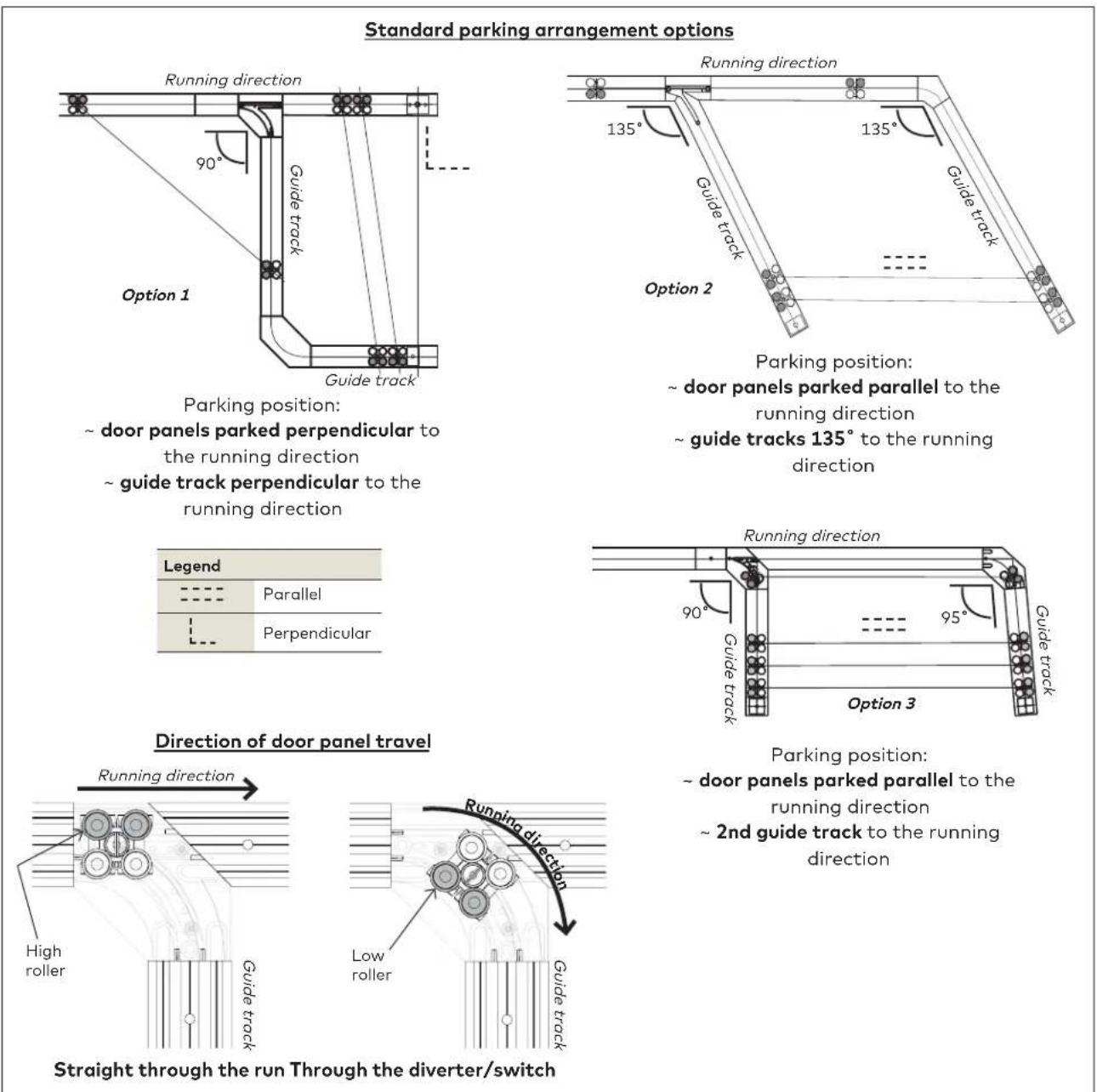
| Legend | |
| - - - - | Parallel |
| L-.. | Perpendicular |
2.1.1 FIRST determine the following:
- parking arrangement of the door panels
- location of the corner track (see step 2.4)
- location of the revision piece (see step 2.4)
2.1.2 Note direction which doors will travel:
• Straight through the run
• Through the diverter/switch
2.2 Install single-action pivoting end panel retaining clip
Fig 5
NOTE:
ENSURE THIS STEP IS DONE AT THIS POINT, OTHERWISE THIS CLIP IS EXTREMELY DIFFICULT TO INSTALL AFTER TRACK MOUNTING.
![Retaining clip [for upper pivot]](/content/2026/05/828239/images/ad8edf978a2fcee5bfb54ed278215abe66490f800749f7d0b8ce124451a7c206.jpg)
| Tools required | |
| Retaining clip | pliers |
2.2.1 Insert retaining clip [for upper pivot] into [end of] track using pliers prior to mounting track to ceiling surface.
2.3 Install door track stop in stacking area
Fig 6
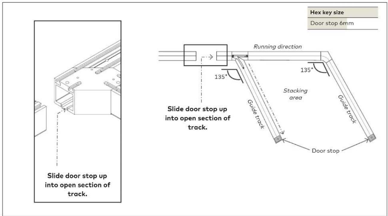
2.3.1 Slide door stop into open section of track.
2.3.2 Slide back into stacking area on opposite side of swing door pivot.
2.3.3 Secure with included fastener.
2.4 Installing the track
Fig 7
![(Example parking arrangement ONLY) 12" [300] 12" [300] Substructure Revision piece Diverter/ switch 12" [300] Stacking area 95° Track Clamping pieces Corner track Clamping piece set screws Track pins Hex key size Clamping piece set screws 3mm Drill bit size Substructure Dependent upon substructure material](/content/2026/05/828239/images/9e2fcbfc9429c751db4ced0ae027908faff58e6ee9ef8a73f487484d3f919134.jpg)
2.4.1 Pre-connect all straight and corner track with clamping pieces.
2.4.2 Slide pins inside track groove for later use.
2.4.3 Align track on ceiling accordingly. Mark and drill substructure hole locations.
- Straight run holes: approximately 11-13/16" [300] apart
- Stacking area holes: approximately 4" [100] apart
2.4.4 Secure the track, along its entire length, including the stacking area, to the substructure.
- Use fasteners appropriate for substructure material.
NOTE: REVISION PIECE IS INSTALLED IN STEP 2.7.
2.4.5 Fully tighten clamping piece set screws.
2.5 Installing upper pivot block
Fig 8
![Upper pivot block Slide pivot block up into open section of track, and into straight run. Stacking area Set screws Upper pivot block Hex key size Upper pivot 5mm Upper pivot block ≈ 2-3/4" [70]](/content/2026/05/828239/images/173b0fe3b7c66d2d10b64ab088c6df4451ff30f2177955c703662f970ff469dc.jpg)
2.5.1 Slide pivot block into open section of track and into straight track run, as shown.
2.5.2 Hand tighten with set screws to hold in place.
2.5.3 Align upper pivot block with center of floor pivot/closer spindle.
2.5.4 Fully tighten set screws.
2.6 Install rollers in track
Fig 9

natural_image
Technical line drawing of a mechanical assembly with a bracket and mounting base (no text or symbols)Slide rollers up into open section of track.

DIRECTION OF DOOR PANEL TRAVEL


NOTE: ENSURE TRACK IS CLEAN OF SOLID DEBRIS AND GREASE.
2.6.1 Determine the arrangement of the rollers depending upon movement of panel. See images above.
NOTE: A "straight through the run" and "through the switch" roller will be needed for each panel.
2.6.2 Remove roller access, if applicable.
2.6.3 Slide rollers up through open section of track and temporarily into stacking area.
NOTE: The roller insertion [into the track] order is irrelevant; only ensure there are an equal number of properly-oriented rollers in each leg of the stacking area.
2.7 Install revision piece
Fig 10

2.7.1 Align revision piece into track via the alignment bars in the track.
2.7.2 Secure using required fastener.
2.7.3 Using a screw driver and mallet, tap pre-installed dowels in either direction so they span across track and revision piece.
2.8 Prepare the roller pattern in the track
Fig 11
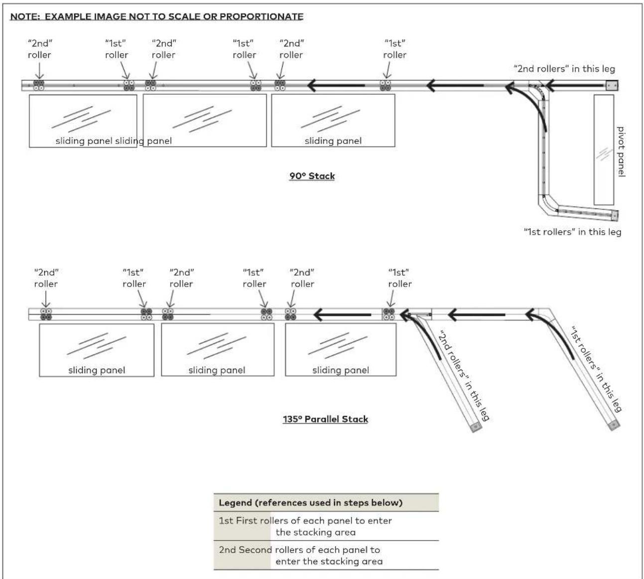
2.8.1 Slide all rollers out from stacking area and into straight run of track in ALTERNATING order listed below:
- Always slide a pair of rollers out for each panel:
»one "1st" roller and one "2nd" roller
»ALWAYS SLIDE THE "2nd" ROLLERS OUT (FOR EACH PANEL) FIRST.
3 Installation instructions - DA & SA pivoting end panel
3.1 Preparing the DA & SA pivoting end panel (with monolithic glass only)
Fig 12
![3/16" [5] Edge of glass to edge of rail 3/16" [5] C 1/16" [1.5] min Hex key size Rails 5mm Torque values Rails 12ft lbs [15Nm] Shim block 1/16" [1.5] min](/content/2026/05/828239/images/55c47e5b799a315cbd49773c21d1779bf1dea33b0acafc98ee6dcbaa309f995b.jpg)
NOTE: FULLY CLEAN SURFACE OF GLASS WITH AN ALCOHOL-BASED MILD GLASS AND SURFACE CLEANER.
! ENSURE RAIL GASKET IS FREE OF DEBRIS.
NOTE: ENSURE RAILS ARE SQUARE PRIOR TO HANGING DOOR TO AVOID EXCESSIVE DOOR ADJUSTMENT ONCE PANEL IS INSTALLED. MEASURE FOR CORRECT PANEL HEIGHT.
3.1.1 Lay glass panel on a flat surface.
3.1.1 Loosen rail screws.
NOTE: If bottom rail contains locking mechanism, ensure rail is in proper orientation for lock usage.
3.1.2 Slide rails onto top and bottom of glass panel.
NOTE: Place shim blocks in bottom rail.
3.1.3 Fully tighten and torque rail screws.
3.2 Preparing the DA & SA pivoting end panel (with tempered laminated glass only)
Fig 13
![3/16" [5] Edge of glass to edge of rail 3/16" [5] C step 2.4 1/16" [1.5] min Shim block Hex key size Rails 5mm Torque values Rails 12ft lbs [15Nm] 1/16" [1.5] min](/content/2026/05/828239/images/5725a03ff274867f217be1944dff775f41e91b4b38a8f67f3f53945dc6df7cb3.jpg)
NOTE: THE RECOMMENDED ADHESIVE'S SET-UP TIME IS 20 MINUTES FOR THE DUO-PAK CARTRIDGES.
NOTE: USE 1:1 RATIO PLUNGER WITH THE 3M™ Scotch-Weld™ Urethane Adhesive.
NOTE: FULLY CLEAN SURFACE OF GLASS WITH AN ALCOHOL-BASED MILD GLASS AND SURFACE CLEANER. ENSURE NO DEBRIS IS ON THE GASKET.
NOTE: ENSURE RAILS ARE SQUARE PRIOR TO SECURING WITH ADHESIVE DOOR TO AVOID EXCESSIVE DOOR ADJUSTMENT ONCE PANEL IS INSTALLED. MEASURE FOR CORRECT PANEL HEIGHT.
3.2.1 Lay glass panel on a flat surface.
3.2.1 Loosen rail screws.
NOTE: If bottom rail contains locking mechanism, ensure rail is in proper orientation for lock usage.
3.2.2 Slide rails onto top and bottom of glass panel.
NOTE: Place shim blocks in bottom rail.
3.2.3 Fully tighten and torque rail screws.
NOTE: Onto scrap material, first dispense approximately 12" of 3M™ Scotch-Weld™ Urethane Adhesive prior to application to prevent mixing errors and ensure optimal hardening.
3.2.4 Dispense into filling holes in rails.
Stop application when adhesive can be seen past edge of rail.
DO NOT WIPE any excess adhesive from glass surface. Allow adhesive to dry and scrape off glass surface with a beveled-edge chisel or putty knife.
3.3 Preparing the upper pivot block
Fig 14
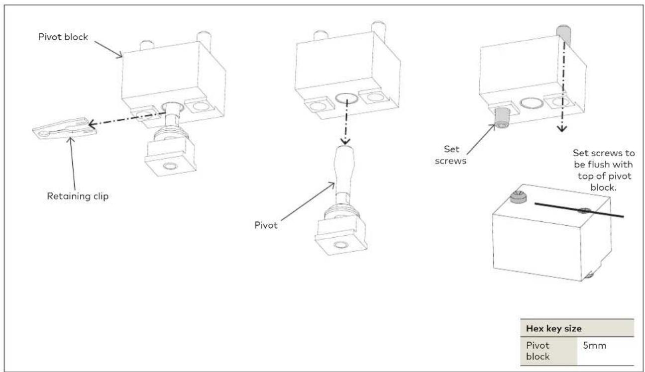
3.3.1 (Retaining clip removed in step 2.2.)
3.3.2 Slide the pivot from the pivot block.
(Set aside.)
3.3.3 Loosen set screws and make flush with top of pivot block.
3.4 Install floor pivot or BTS80 closer
Fig 15
![Floor pivot ≈ 2-3/4" [70] Floor pivot Washers ±1/8" [±3] 1/2" [13] Ø 1-9/16" [Ø 40] BTS80 floor closer For floor pivot or BTS closer 3/8" [10] 2-3/8" [60] 3-1/8" [78] Drill bit size Floor pivot/ BTS80 closer Dependent upon flooring material](/content/2026/05/828239/images/cc78799bd6765011dae3faae263040d11ade20336ddb63086c6d6703fcf34ca1.jpg)
3.4.1 Align floor pivot or BTS80 closer 2-3/4" [70] from door jamb.
3.4.2 (Floor pivot): Use 3 included washers to create appropriate door spacing.
Ensure pivot/closer are plumb and level.
3.4.3 Mark and drill holes, and recess into flooring surface.
3.4.4 (Floor pivot): Insert anchors if necessary.
3.4.5 Secure pivot/BTS closer to floor surface using appropriate fasteners.
3.5 Install pivot into end panel carrier profile
Fig 16
![Wrench size Pivot bolt 8mm Pivot nut 17mm Pivot bolt Pivot Pivot nut 2-3/8" [60.5] Washers Carrier profile Top rail](/content/2026/05/828239/images/0aaee6083e3e8ce2fc4e5044f718d4f7b5bea7a168d5723c682ee05a451ea9a3.jpg)
3.6.1 Loosen nut.
3.5.2 Lower bolt by rotating to allow for clearance.
3.5.3 Slide pivot into carrier profile as shown.
NOTE: Ensure washers are above carrier profile.
3.6.4 Set pivot at 2-3/8" [60.5] from end of rail.
3.6 Install top cover gasket
Fig 17

3.6.1 Push gasket into top cover.
3.7 Installing top covers
Fig 18

3.7.1 Snap covers onto rails.
3.8 Install DA & SA pivoting end panel into track
Fig 19

3.8.1 Rest assembled panel on 3/8" [10] shim blocks.
3.8.2 Lower pivot pin down as far as it will go.
3.8.3 Tip glass and pivot up into upper pivot block.
3.8.4 Lower down onto floor pivot.
3.8.5 Ensure door is plumb and level.
3.8.6 Adjust door height up or down accordingly.
3.8.7 Tighten upper pivot block in place.
3.8.8 Rotate door into stacking area.
3.9 Secure end panel in track
Fig 20

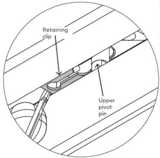
| Tools required | |
| Retaining clip | flat head screw driver |
| rubber mallet | |
3.9.1 Slide retaining clip inside track groove and tap/snap into place around upper pivot pin.
- Use screw driver and rubber mallet.
4 Installation instructions - Sliding panel
4.1 Preparing the sliding panel (with monolithic glass only)
Fig 21
![3/16" [5] Edge of glass to edge of rail 3/16" [5] 1/16" [1.5] min Hex key size Rails 5mm Torque values Rails 12ft lbs [15Nm] Shim block 1/16" [1.5] min](/content/2026/05/828239/images/a6465071e4404bd83b7b41f39989b1b40058e3df9307c9a6116ba891de1c7f76.jpg)
NOTE: FULLY CLEAN SURFACE OF GLASS WITH AN ALCOHOL-BASED MILD GLASS AND SURFACE CLEANER.
⚠️ ENSURE RAIL GASKET IS FREE OF DEBRIS.
NOTE: ENSURE RAILS ARE SQUARE PRIOR TO HANGING DOOR TO AVOID EXCESSIVE DOOR ADJUSTMENT ONCE PANEL IS INSTALLED. MEASURE FOR CORRECT PANEL HEIGHT.
4.1.1 Lay glass panel on a flat surface.
4.1.1 Loosen rail screws.
NOTE: If bottom rail contains locking mechanism, ensure rail is in proper orientation for lock usage.
4.1.2 Slide rails onto top and bottom of glass panel.
NOTE: Place shim blocks in bottom rail.
4.1.3 Fully tighten and torque rail screws.
4.2 Preparing the sliding panel (with tempered laminated glass only)
Fig 22
![3/16" [5] Edge of glass to edge of rail 3/16" [5] C step 2.4 1/16" [1.5] min Shim block Hex key size Rails 5mm Torque values Rails 12ft lbs [15Nm] 1/16" [1.5] min](/content/2026/05/828239/images/1170ab317185d80039e638677b254591c57229c4d8c98c91a5bce8cb29828396.jpg)
NOTE: THE RECOMMENDED ADHESIVE'S SET-UP TIME IS 20 MINUTES FOR THE DUO-PAK CARTRIDGES.
NOTE: USE 1:1 RATIO PLUNGER WITH THE 3M^TM Scotch-Weld™ Urethane Adhesive.
NOTE: FULLY CLEAN SURFACE OF GLASS WITH AN ALCOHOL-BASED MILD GLASS AND SURFACE CLEANER. ENSURE NO DEBRIS IS ON THE GASKET.
NOTE: ENSURE RAILS ARE SQUARE PRIOR TO SECURING WITH ADHESIVE TO AVOID EXCESSIVE DOOR ADJUSTMENT ONCE PANEL IS INSTALLED. MEASURE FOR CORRECT PANEL HEIGHT.
4.2.1 Lay glass panel on a flat surface.
4.2.1 Loosen rail screws.
NOTE: If bottom rail contains locking mechanism, ensure rail is in proper orientation for lock usage.
4.2.2 Slide rails onto top and bottom of glass panel.
NOTE: Place shim blocks in bottom rail.
4.2.3 Fully tighten and torque rail screws.
NOTE: Onto scrap material, first dispense approximately 12" of 3M™ Scotch-Weld™ Urethane Adhesive prior to application to prevent mixing errors and ensure optimal hardening.
4.2.4 Dispense into filling holes in rails.
Stop application when adhesive can be seen past edge of rail.
DO NOT WIPE any excess adhesive from glass surface. Allow adhesive to dry and scrape off glass surface with a beveled-edge chisel or putty knife.
4.3 Install sliding panel onto rollers and adjust door height
Fig 23
![Track Nuts: twist apart so washers rest above profile Washers Carrier profile Top rail Shim blocks 2-9/16" [65] from edge of glass 3/8" [10] Ensure min. gap without covers. Wrench size Roller 17mm nuts](/content/2026/05/828239/images/9ac917d5f7a180538b384aaffd202bc638306adf905c144e3d807886357bf623.jpg)
4.3.1 Rest glass panel on 3/8" [10] shim blocks.
4.3.2 Ensure one roller is on each side of panel.
4.3.3 Insert rollers into carrier profile:
• REFER TO STEP 2.8 FOR ROLLER PATTERN.
- Twist nuts apart such that washers will rest above carrier profile.
- Sliding panels: slide one roller into each end of the carrier profile. (a "2nd" and a "1st" for each)
NOTE: For perpendicular stacking: center of "2nd" roller must be 2-9/16" [65] from edge of glass.
NOTE: For parallel stacking: roller are adjustable.
4.3.4 Slide panels into stacking area, and allow "1st" roller to naturally settle into place within the carrier profile.
4.3.5 Then, slide all panels out into the straight run again for horizontal adjustment.
- Loosen lower nut.
- Rotate upper nut to raise or lower door.
- Ensure a minimum 3/8" [10] gap between bottom of door and floor (without covers).
4.3.7 DO NOT FULLY TIGHTEN NUTS AT THIS POINT.
4.4 Install gasket and top cover
Fig 24

4.4.1 Push gasket into top cover.
4.4.2 Snap covers onto rails.
5 Installation instructions - Double-action sliding panel with ITS96
5.1 Preparing the DA sliding panel (with monolithic glass)
Fig 25
![3/16" [5] Edge of glass to edge of rail 3/16" [5] 1/16" [1.5] min Hex key size Rails 5mm Torque values Rails 12ft lbs [15Nm] Shim block 1/16" [1.5] min](/content/2026/05/828239/images/bd26102093aa45d55c0e865899a29a91c45ed635c907ae9c44598c3e3a8cff96.jpg)
NOTE: FULLY CLEAN SURFACE OF GLASS WITH AN ALCOHOL-BASED MILD GLASS AND SURFACE CLEANER.
⚠️ ENSURE RAIL GASKET IS FREE OF DEBRIS.
NOTE: ENSURE RAILS ARE SQUARE PRIOR TO HANGING DOOR TO AVOID EXCESSIVE DOOR ADJUSTMENT ONCE PANEL IS INSTALLED. MEASURE FOR CORRECT PANEL HEIGHT.
5.1.1 Lay glass panel on a flat surface.
5.1.1 Loosen rail screws.
NOTE: If bottom rail contains locking mechanism, ensure rail is in proper orientation for lock usage.
5.1.2 Slide rails onto top and bottom of glass panel.
NOTE: Place shim blocks in bottom rail.
5.1.3 Fully tighten and torque rail screws.
5.2 Preparing the DA sliding panel
(with tempered laminated glass only)
Fig 26
![3/16" [5] Edge of glass to edge of rail 3/16" [5] C step 2.4 1/16" [1.5] min Shim block Hex key size Rails 5mm Torque values Rails 12ft lbs [15Nm]](/content/2026/05/828239/images/2ed7c0b9410a1ab9e8607e747af53acb5c73bb6244c484e82e8944ffaac69970.jpg)
NOTE: THE RECOMMENDED ADHESIVE'S SET-UP TIME IS 20 MINUTES FOR THE DUO-PAK CARTRIDGES.
NOTE: USE 1:1 RATIO PLUNGER WITH THE 3M^TM Scotch-Weld™ Urethane Adhesive.
NOTE: FULLY CLEAN SURFACE OF GLASS WITH AN ALCOHOL-BASED MILD GLASS AND SURFACE CLEANER. ENSURE NO DEBRIS IS ON THE GASKET.
NOTE: ENSURE RAILS ARE SQUARE PRIOR TO SECURING WITH ADHESIVE TO AVOID EXCESSIVE DOOR ADJUSTMENT ONCE PANEL IS INSTALLED. MEASURE FOR CORRECT PANEL HEIGHT.
5.2.1 Lay glass panel on a flat surface.
5.2.1 Loosen rail screws.
NOTE: If bottom rail contains locking mechanism, ensure rail is in proper orientation for lock usage.
5.2.2 Slide rails onto top and bottom of glass panel.
NOTE: Place shim blocks in bottom rail.
5.2.3 Fully tighten and torque rail screws.
NOTE: Onto scrap material, first dispense approximately 12" of 3M™ Scotch-Weld™ Urethane Adhesive prior to application to prevent mixing errors and ensure optimal hardening.
5.2.4 Dispense into filling holes in rails.
Stop application when adhesive can be seen past edge of rail.
DO NOT WIPE any excess adhesive from glass surface. Allow adhesive to dry and scrape off glass surface with a beveled-edge chisel or putty knife.
5.3 Installing three piece lock
Fig 27
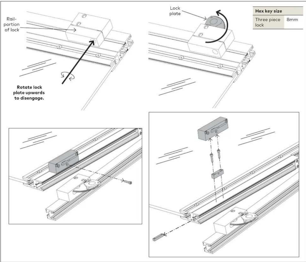
5.3.1 Rotate lock plate up to disengage from the rail, via screw in rail-portion of the lock.
5.3.2 Remove lock parts on rail and set aside for later reinstall.
5.4 Prep for installing two piece lock (when required)
Fig 28
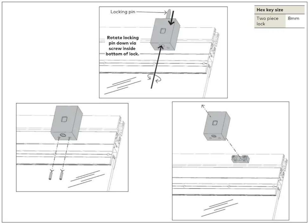
| Hex key size | |
| Two piece lock | 8mm |
5.4.1 Rotate locking pin down via screw inside bottom of the lock.
5.4.2 Remove lock parts and set aside for later reinstall.
5.5 Install top cover and carrier profile gaskets
Fig 29
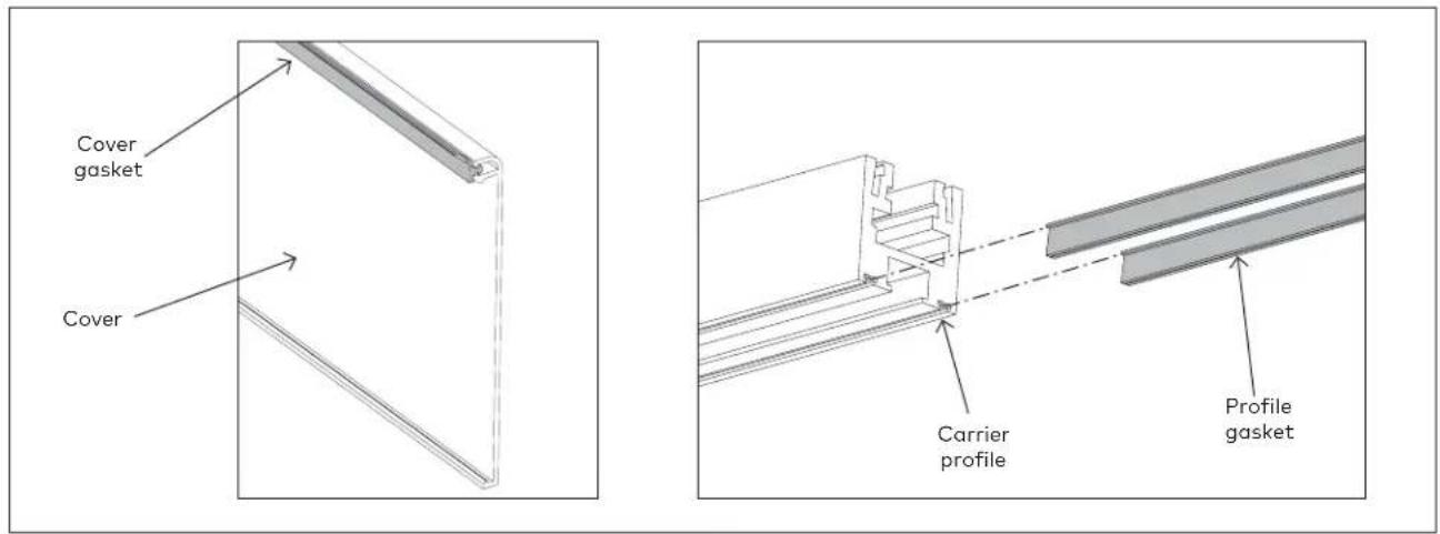
5.5.1 Press cover gasket into top cover.
5.5.2 Slide profile gasket into carrier profile.
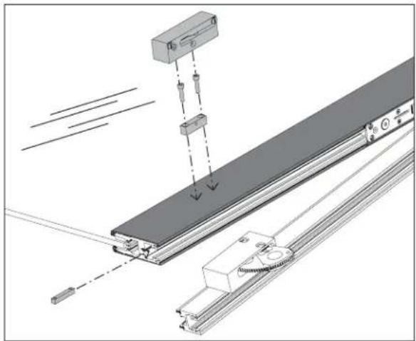
5.6 Installing three piece lock (continued)
Fig 30

natural_image
Technical diagram of a mechanical assembly with motion lines and components (no text or symbols)
natural_image
Technical line drawing of a mechanical assembly with railings and components (no text or symbols)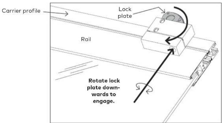
| Hex key size | |
| Three piece lock | 8mm |
5.6.1 Secure rail covers.
5.6.2 Reinstall lock parts over covers.
5.6.3 Rotate lock plate down to lock carrier profile and rail together.
- Use screw in rail-portion of the lock.
5.7 Install two piece lock (continued)
Fig 31

Two piece lock
8mm
5.7.1 Reinstall lock parts over covers onto carrier profile.
5.8 Installing DA sliding panels onto rollers and adjust door height
Fig 32
![Track Nuts: twist apart so washers rest above profile Washers Carrier profile Top rail Shim blocks 2-9/16" [65] from edge of glass Wrench size Roller 17mm nuts 3/8" [10] Ensure min. gap without covers. Legend (references used in steps below) 1st First rollers of each panel to enter the stacking area 2nd Second rollers of each panel to enter the stacking area](/content/2026/05/828239/images/e3042049958f5d7402faa2de5b0d0c80f17b5b169ec3ee7d71aa4da94b4d0cfa.jpg)
5.8.1 Rest glass panel on 3/8" [10] shim blocks.
5.8.2 Ensure one roller is on each side of panel.
5.8.3 Insert rollers into carrier profile:
• REFER TO STEP 2.8 FOR ROLLER PATTERN.
- Twist nuts apart such that washers will rest above carrier profile.
- Sliding panels: slide one roller into each end of the carrier profile. (a "2nd" and a "1st" for each)
NOTE: For perpendicular stacking: center of "2nd" roller must be 2-9/16" [65] from edge of glass.
NOTE: For parallel stacking: rollers are adjustable.
5.8.4 Slide panels into stacking area, and allow "1st" roller to naturally settle into place within the carrier profile.
5.8.5 Then, slide all panels out into the straight run again for horizontal adjustment.
5.8.6 Adjust door height:
- Loosen lower nut.
- Rotate upper nut to raise or lower door.
- Ensure a minimum 3/8" [10] gap between bottom of door and floor (without covers).
5.8.7 DO NOT FULLY TIGHTEN NUTS AT THIS POINT.
5.9 Secure three piece lock to track
Fig 33
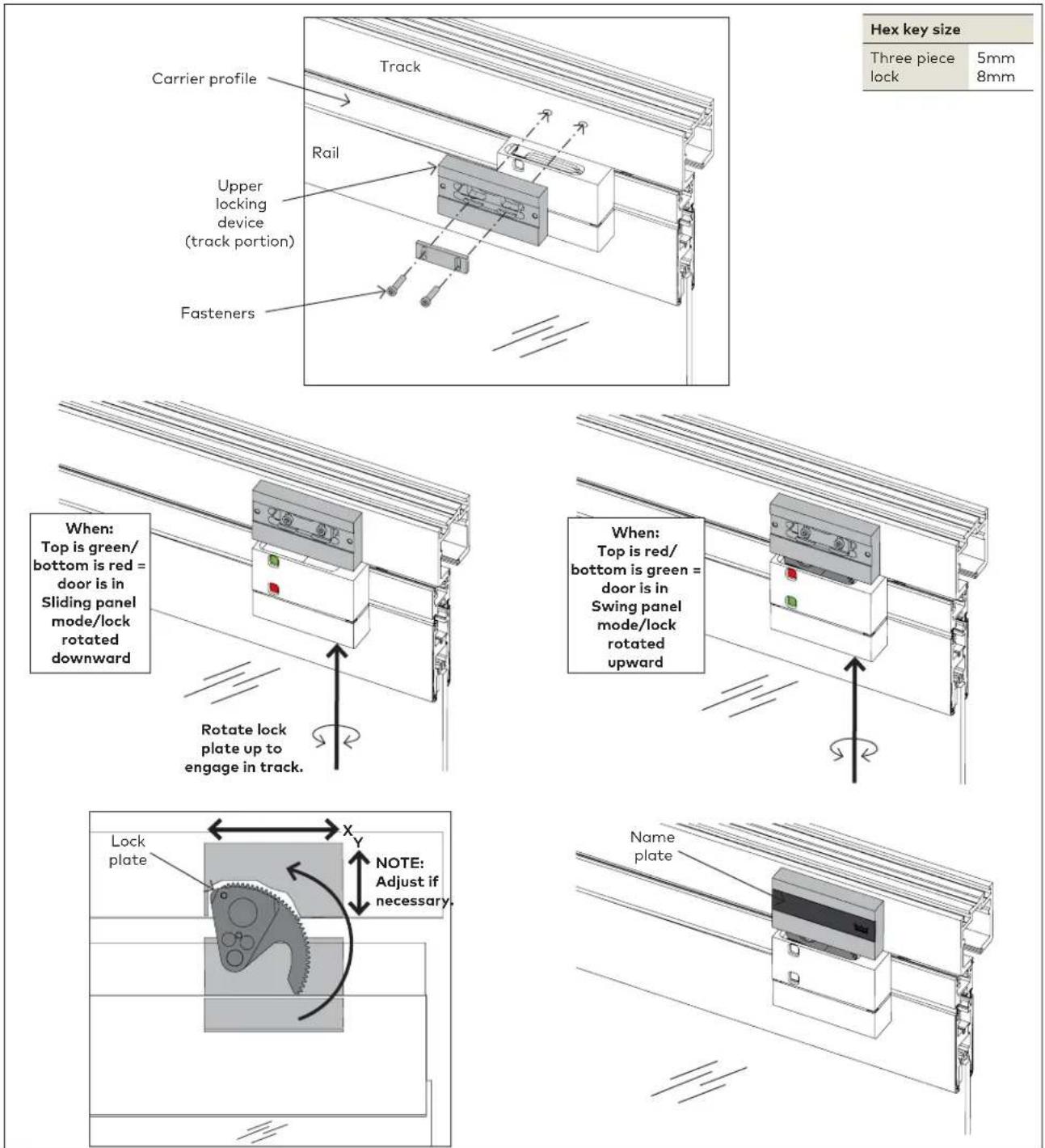
5.9.1 Secure upper locking device parts to track.
- Hand tighten only.
5.9.2 Rotate locking plate up to engage in track portion of lock.
- Use screw via lower section of locking device.
5.9.3 Adjust track portion of locking device horizontally [x] and vertically [y] to ensure proper engagement.
• Fully tighten fasteners.
5.9.4 Place dormakaba name plate over front of lock.
5.9.5 To put in sliding panel mode: rotate locking plate up to engage in track portion of lock.
To put in swing panel mode: rotate locking plate down to disengage from track portion of lock.
5.10 Secure two piece lock to track
Fig 34
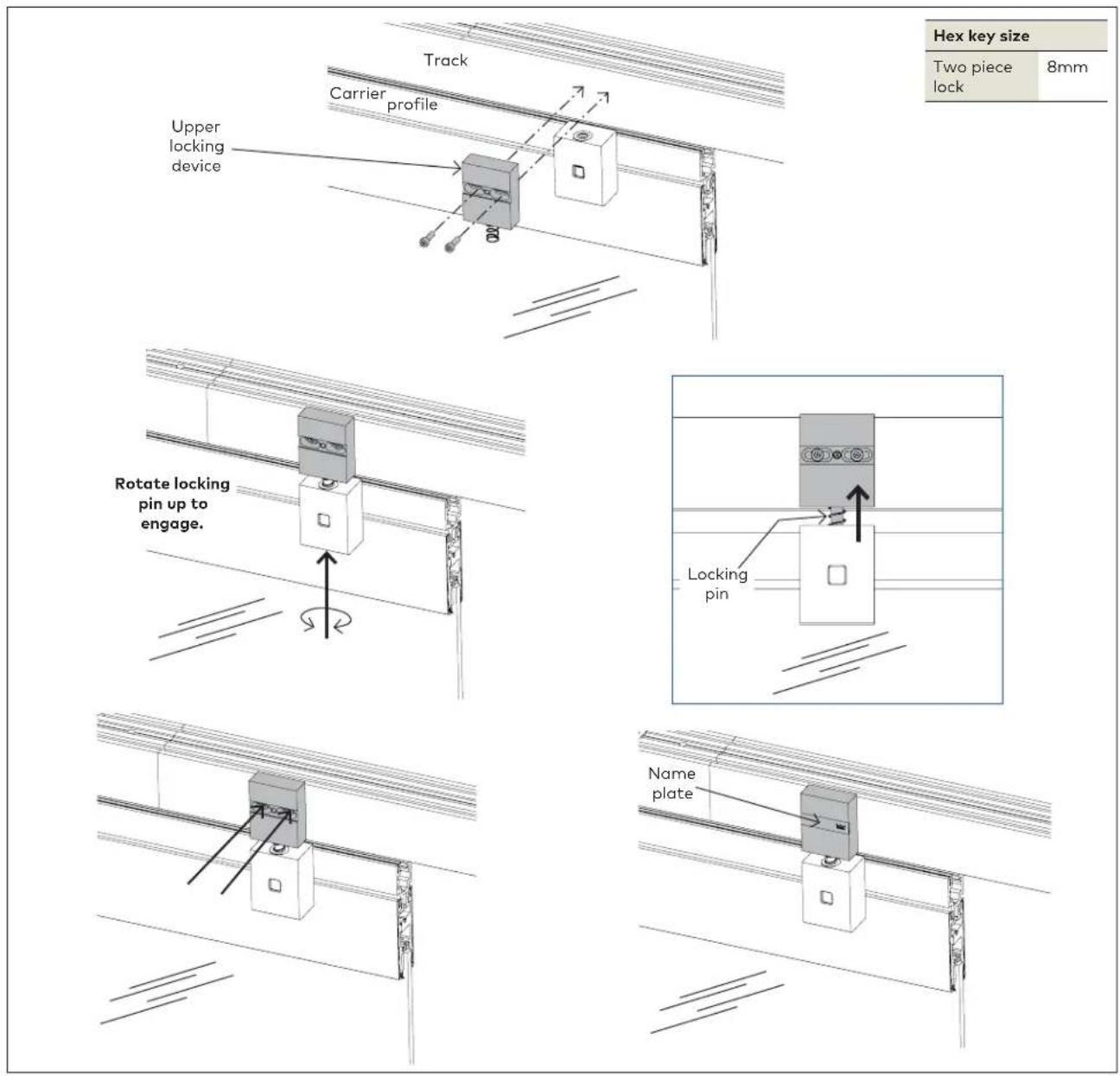
5.10.1 Secure upper locking device parts to track.
- Hand tighten only.
5.10.2 Rotate locking pin up to engage.
- Use screw via lower section of locking device.
5.10.3 Adjust track portion of locking device horizontally and vertically to ensure proper engagement of pin.
• Fully tighten fasteners.
5.10.4 Place dormakaba name plate over front of lock.
5.10.5 To open door/unlock: rotate locking pin up to engage.
To lock: rotate locking pin down to disengage.
5.11 ITS96 closer adjustment
Fig 35
![Hex key size ITS closer adjustment 3mm HRSE W. GRAVY Rail Carrier profile ILS closer Adjust location inside rail ±1/16" [±2] Rail Latch Sweep ITS 88 EN 2-4 Adjust sweep and latch valves Deadstop Adjust deadstop Sweep (120° - 0°) Latch (7° - 0°)](/content/2026/05/828239/images/23057129fb24bf8acc12033c3753146bf0d594537c0f1e4698e8428549bf5b94.jpg)
5.11.1 Adjust the ITS closer location inside the rail.
NOTE: Ensure it is centered inside the rail.
NOTE: Closer is already pre-loaded at 45°. Not further pre-loading steps are needed.
Adjust deadstop:
5.11.2 Open door to desired opening between 80° and 120°.
5.11.3 Slide deadstop cushion into place.
5.11.4 Tighten deadstop screw.
Adjust sweep and latch:
5.11.5 Adjust via set screws in top of closer.
- Sweep: increase or decrease
- Latch: increase only
5.12 ITS96 hold open (optional) and spring force adjustment
Fig 36

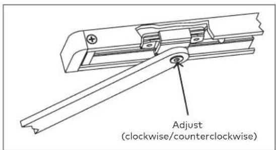

BARRIER-FREE OPENINGS - Adjust only if more tension is required to close and latch the door. Depending on opening conditions, a door adjusted to meet barrier-free forces may not have sufficient power to reliably close and latch the door.
NON-BARRIER-FREE OPENINGS - Adjust according to chart.
| Door width (Interior) | Maximum door weight (lbs) | Full turns of spring adjuster (ITS9613) | Full turns of spring adjuster (ITS9625) | Spring size |
| 2'-6" 100 8 N/A 2 | ||||
| 3'-0" 125 15 -5 3 | ||||
| 3'-6" 150 N/A 0 4 | ||||
| 4'-0" 175 N/A 8 5 |

5.12.1 Open door and place hold open mechanism in desired position.
5.12.2 Secure mechanism in place.
5.12.3 Adjust hold open:
- Increase force = turn clockwise
- Decrease force = turn counter clockwise
5.12.4 To enable hold open: open door and push arm slide onto hold open mechanism.
5.12.5 To disable hold open: close door and pull arm slide off of hold open mechanism.
5.12.6 Adjust spring force:
- Increase spring force = turn clockwise
- Decrease spring force = turn counter clockwise
6 Installation instructions - Fixed panel door
6.1 Preparing the fixed panel door (with monolithic glass only)
Fig 37
![3/16" [5] Edge of glass to edge of rail 3/16" [5] 1/16" [1.5] min Hex key size Rails 5mm Torque values Rails 12ft lbs [15Nm] Shim block 1/16" [1.5] min](/content/2026/05/828239/images/9d4399f8cf00a54e24aa732bff1e51656cac101ff29ba864991faac4a2477301.jpg)
NOTE: FULLY CLEAN SURFACE OF GLASS WITH AN ALCOHOL-BASED MILD GLASS AND SURFACE CLEANER.
⚠️ ENSURE RAIL GASKET IS FREE OF DEBRIS.
NOTE: ENSURE RAILS ARE SQUARE PRIOR TO HANGING DOOR TO AVOID EXCESSIVE DOOR ADJUSTMENT ONCE PANEL IS INSTALLED. MEASURE FOR CORRECT PANEL HEIGHT.
6.1.1 Lay glass panel on a flat surface.
6.1.1 Loosen rail screws.
NOTE: If bottom rail contains locking mechanism, ensure rail is in proper orientation for lock usage.
6.1.2 Slide rails onto top and bottom of fixed glass panel.
NOTE: Place shim blocks in bottom rail.
6.1.3 Fully tighten and torque rail screws.
6.2 Preparing the fixed panel door (with tempered laminated glass only)
Fig 38
![3/16" [5] Edge of glass to edge of rail 3/16" [5] step 2.4 1/16" [1.5] min Shim block Hex key size Rails 5mm Torque values Rails 12ft lbs [15Nm]](/content/2026/05/828239/images/a5e840c8709d77f813304d3eb1f596d1d6545a63b721de3e17f9e67c8e83b12a.jpg)
NOTE: THE RECOMMENDED ADHESIVE'S SET-UP TIME IS 20 MINUTES FOR THE DUO-PAK CARTRIDGES.
NOTE: USE 1:1 RATIO PLUNGER WITH THE 3M™ Scotch-Weld™ Urethane Adhesive.
NOTE: FULLY CLEAN SURFACE OF GLASS WITH AN ALCOHOL-BASED MILD GLASS AND SURFACE CLEANER. ENSURE NO DEBRIS IS ON THE GASKET.
NOTE: ENSURE RAILS ARE SQUARE PRIOR TO SECURING WITH ADHESIVE TO AVOID EXCESSIVE DOOR ADJUSTMENT ONCE PANEL IS INSTALLED. MEASURE FOR CORRECT PANEL HEIGHT.
6.2.1 Lay glass panel on a flat surface.
6.2.1 Loosen rail screws.
NOTE: If bottom rail contains locking mechanism, ensure rail is in proper orientation for lock usage.
6.2.2 Slide rails onto top and bottom of fixed glass panel.
NOTE: Place shim blocks in bottom rail.
6.2.3 Fully tighten and torque rail screws.
NOTE: Onto scrap material, first dispense approximately 12" of 3M™ Scotch-Weld™ Urethane Adhesive prior to application to prevent mixing errors and ensure optimal hardening.
6.2.4 Dispense into filling holes in rails.
Stop application when adhesive can be seen past edge of rail.
DO NOT WIPE any excess adhesive from glass surface. Allow adhesive to dry and scrape off glass surface with a beveled-edge chisel or putty knife.
6.3 Installing the fixed panel holders
Fig 39
![Wrench size Fixed panel holder nut 17mm Carrier profile Fixed panel holder nut 2-3/8" [60.5] Carrier profile Top door rail](/content/2026/05/828239/images/4f41eb25a769ab3d74b355e374dabec0355f4e176582cd31f785e3e286352d4d.jpg)
6.3.1 Loosen fixed panel holder nut.
6.3.2 Slide holders into each end of the carrier profile at the top of the door.
6.3.3 Ensure fixed panel holder is 2-3/8" [60.5] from edge of rail and nut sits above the profile.
6.3.4 Hand tighten nuts.
6.4 Installing the saddle and fixed panel door
Fig 40
![ENSURE DOOR IS PLUMB AND LEVEL LIFT DOOR PANEL UP INTO TRACK. THEN, LOWER DOWN ONTO SADDLE. Saddle Bottom rail of door 2" [50] 2" [50]](/content/2026/05/828239/images/967a138e87cc51c43df295d79b683b15301fb2bed531caf13a948b16c2d2a65e.jpg)
6.4.1 Locate centerline of track using laser or plumbob.
6.4.2 Align saddle with centerline of track.
6.4.3 Mark and pre-drill holes in the floor surface.
6.4.4 Secure saddle to floor using fasteners appropriate to the floor surface material.
6.4.5 Lift door panel up into track.
6.4.6 Lower door panel down onto saddle.
6.5 Adjusting and securing fixed panel door
Fig 41
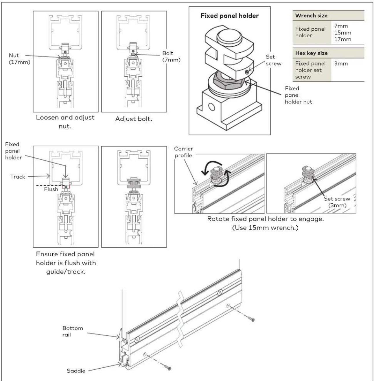
| Wrench size | |
| Fixed panel holder | 7mm15mm17mm |
| Hex key size | |
| Fixed panel holder set screw | 3mm |
ed el der nut
6.5.1 Loosen fixed panel holder nut.
6.5.2 Adjust nut and bolt until fixed panel holder is flush with track.
6.5.3 Rotate fixed panel holder 90° inside track to engage.
6.5.4 Secure fixed panel holder via set screw.
6.5.5 Secure door height with nut.
6.5.6 Secure fixed panel door and bottom rail to saddle with proper fasteners.
6.6 Install gasket and top cover
Fig 42

6.6.1 Push gasket into top cover.
6.6.2 Snap covers onto rails.
7 Installation instructions - Alignment, covers, end caps, miscellaneous
7.1 Aligning panels into stacking area
Fig 43
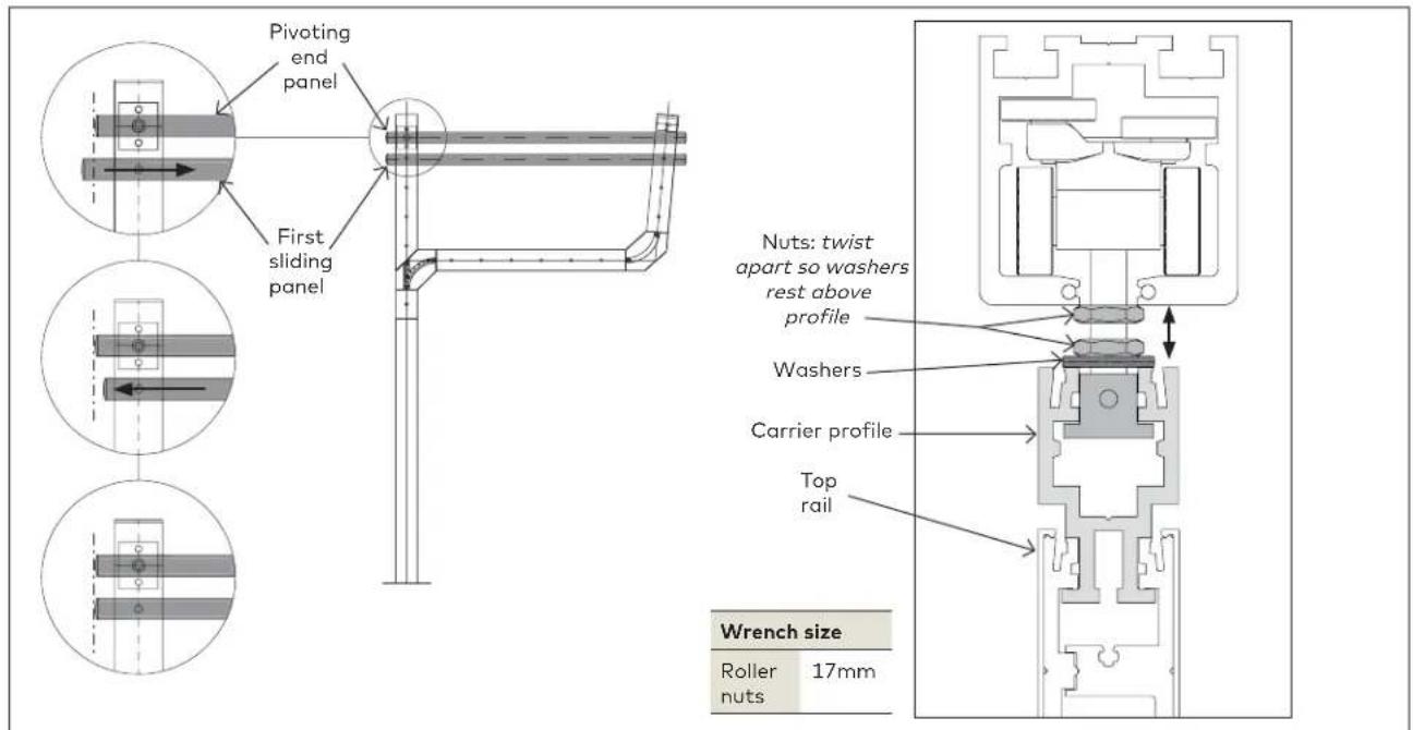
7.1.1 Slide panels back into stacking area accordingly.
7.1.2 With upper nuts loose, slide panel left or right to align each sliding panel with the pivoting end panel. (See image above.)
7.1.3 Fully tighten in place with lower nut.
7.2 Aligning panels side by side in straight run
Fig 44
![Ensure all panels are aligned and parallel across the top. Adjust if necessary. Legend P1 DA/SA end panel P2 Sliding panel P3 DA sliding panel P4 Fixed panel ±3/16" [±5] 3/16" [5] 3/16" [5] 3/16" [5] P1 P4P3P2 3/16" [5] 3/8" [10]](/content/2026/05/828239/images/d1a53c7a8c804caf2656d897d005b1cb878c532d2bd8d3b7550bf69da3dbc364.jpg)
7.2.1 Slide panels into place along straight run of track.
NOTE: Ensure a 3/16" [5] gap between each panel.
NOTE: End cap bumpers should touch when proper gap is achieved. (See step 7.8 for end cap bumpers location.)
NOTE: Ensure all panels are level across the top. Adjust if necessary.
NOTE: Use nut on roller to adjust height and, plumb and align panels. (See step 7.1 for roller nut location).
NOTE: Europe systems will show swing panel opposite of US version.
7.3 Secure carrier profile file connecting inserts and end caps
Fig 45

7.3.1 Sliding panel: slide coordinating male/female connecting inserts and end caps into open ends of carrier profiles.
7.3.2 Fixed panels: select proper end cap dependent upon the type of panel adjacent to it.
- Fixed panel/Fixed panel: each use female connecting insert and end cap
- Fixed panel/Sliding panel: use coordinating male/female connecting insert and end cap
7.3.3 Pivoting end panels: use female connecting insert and end cap into open ends of carrier profile.
7.4 Drilling for ES locking bolt strike
Fig 46
![Eccentric bushing 2-9/16" [65] min. 1-3/16" [min. 30] Ø 1" [Ø 25] Ø 1/8" [Ø 8] ±1/8" [±2.5] Tools required Strike Drill 8mm drill bit 25mm hole saw](/content/2026/05/828239/images/482640244120d9995b06aa56437393b2ddefdd10fb0c10d967465f8c758f16c1.jpg)
7.4.1 With panels in place, lower all strikes down to sit on floor surface.
7.4.2 Mark strike location on floor surface.
7.4.3 Move panels out of the way.
7.4.4 Drill according to specifications in images above.
7.4.5 Drop strike into place.
7.4.6 Secure with included anchor and fastener.
7.4.7 Adjust center of strike location via eccentric bushing inside strike.
7.5 Secure bottom rail covers and rail lock preparation
Fig 47

If using surface lock:
7.5.1 Slide strike bolt cover clip into place.
7.5.2 Push cover gasket into remaining bottom rail covers.
NOTE: Ensure surface bolt is in down position.
7.5.3 Snap bottom covers into place using a mallet and wood block.
7.5.4 Bottom covers: slide surface knob onto bolt.
7.5.5 Tighten with screw.
If using mortise lock:
7.5.1 Push cover gasket into remaining bottom rail covers.
7.5.2 Snap bottom covers into place using a mallet and wood block.
7.5.3 Install mortise cylinder and blocking ring into rail. (NOTE: blocking ring included only with 5-pin cylinders.)
7.5.4 Secure cylinder via set screws inside lock housing.
7.6 Installing the brush
Fig 48

7.6.1 Carrier profile brush:
- slide brush into included brush holder.
- slide brush assembly into carrier profile using the sealing brush wedge. (This will stay in place inside the carrier profile.)
7.6.2 Bottom brush:
- slide brush into bottom cover.
NOTE: Bend slightly to create a small wave in the brush. This will allow it to fit snuggly into the groove and not slide out over time.
7.7 Selecting the proper end cap
Fig 49
flowchart
graph TD
    A["4 types of end caps"] --> B["Sheet metal screws"]
    B --> C1["sheet metal screw"]
    B --> C2 sheet metal screw]
    B --> C3 sheet metal screw]
    B --> C4 sheet metal screw]
    B --> C5 sheet metal screw]
    B --> C6 sliding panel with surface lock
    B --> C7 sliding panel with interconnecting lock
    B --> C8 sliding panel with interconnecting lock
    B --> C9 sliding panel with surface lock
    B --> C10 shdded and shdded with surface lock
    B --> C11 shdded and shdded with surface lock
    B --> C12 shdded and shdded with surface lock
    B --> C13 shdded and shdded with surface lock
    B --> C14 shdded and shdded with surface lock
    B --> C15 shdded and shdded with surface lock
    B --> C16 shdded and shdded with surface lock
    B --> C17 shdded and shdded with surface lock
    B --> C18 shdded and shdded with surface lock
    B --> C19 shdded and shdded with surface lock
    B --> C20 shdded and shdded with surface lock
    B --> C21 shdded and shdded with surface lock
    B --> C22 shdded and shdded with surface lock
    B --> C23 shdded and shdded with surface lock
    B --> C24 shdded and shdded with surface lock
    B --> C25 shdded and shdded with surface lock
    B --> C26 shdded and shdded with surface lock
    B --> C27 shdded and shdded with surface lock
    B --> C28 shdded and shdded with surface lock
    B --> C29 shdded and shdded with surface lock
    B --> C30 shdded and shdded with surface lock
    B --> C31 shdded and shdded with surface lock
    B --> C32 shdded and shdded with surface lock
    B --> C33 shdded and shdded with surface lock
    B --> C34 shdded and shdded with surface lock
    B --> C35 shdded and shdded with surface lock
    B --> C36 shdded and shdded with surface lock
    B --> C37 shdded and shdded with surface lock
    B --> C38 shdded and shdded with surface lock
    B --> C39 shdded and shdded with surface lock
    B --> C40 shdded and shdded with surface lock
    B --> C41 shdded and shdded with surface lock
    B --> C42 shdded and shdded with surface lock
    B --> C43 shdded and shdded with surface lock
    B --> C44 shdded and shdded with surface lock
    B --> C45 shdded and shdded with surface lock
    B --> C46 shdded and shdded with surface lock
    B --> C47 shdded and shdded with surface lock
    B --> C48 shdded and shdded with surface lock
    B --> C49 shdded and shdded with surface lock
    B --> C50 shdded and shdded with surface lock
    B --> C51 shdded and shdded with surface lock
    B --> C52 shdded and shdded with surface lock
    B --> C53 shdded and shdded with surface lock
    B --> C54 shdded and shdded with surface lock
    B --> C55 shdded and shdded with surface lock
    B --> C56 shdded and shdded with surface lock
    B --> C57 shdded and shdded with surface lock
    B --> C58 shdded and shdded with surface lock
    B --> C59 shdded and shdded with surface lock
    B --> C60 shdded and shdded with surface lock
    B --> C61 shdded and shdded with surface lock
    B --> C62 shdded and shdded with surface lock
    B --> C63 shdded and shdded with surface lock
    B --> C64 shdded and shdded with surface lock
    B --> C65 shdded and shdded with surface lock
    B --> C66 shdded and shdded with surface lock
    B --> C67 shdded and shdded with surface lock
    B --> C68 shdded and shdded with surface lock
    B --> C69 shdded and shdded with surface lock
    B --> C70 shdded and shdded with surface lock
    B --> C71 shdded and shdded with surface lock
    B --> C72 shdded and shdded with surface lock
    B --> C73 shdded and shdded with surface lock
    B --> C74 shdded and shdded with surface lock
    B --> C75 shdded and shdded with surface lock
    B --> C76 shdded and shdded with surface lock
    B --> C77 shdded and shdded with surface lock
    B --> C78 shdded and shdded with surface lock
    B --> C79 shdded and shdded with surface lock
    B --> C80 shdded and shdded with surface lock
    B --> C81 shdded and shdded with surface lock
    B --> C82 shdded and shdded with surface lock
    B --> C83 sheal metal screw, sheet metal screw, machine screw, sliding panel with supercap, sliding panel with intercap, sliding panel with intercap, sliding panel with supercap, sliding panel with supercap, sliding panel with supercap, sliding panel with supercap, sliding panel with supercap, sliding panel with supercap, sliding panel with supercap, sliding panel with supercap, sliding panel with supercap, sliding panel with supercap, sliding panel with supercap, sliding panel with supercap, sliding panel with supercap, sliding panel with supercap, sliding panel with supercap, sliding panel with supercap, sliding panel with supercap, sliding plate, sheet metal screw, machine screw, sliding metal screw, machine screw, sliding metal screw, sliding metal screw, sliding metal screw, sliding metal screw, sliding metal screw, sliding metal screw, sliding metal screw, sliding metal screw, sliding metal screw, sliding metal screw, sliding metal screw, sliding metal screw, sliding metal screw, sliding metal screw, sliding metal screw, sliding metal screw, sliding metal screw, sliding metal screw, sliding metal screw, sliding metal screw, sliding metal screw, sliding metal screw, sliding metal screw, sliding metal screw, sliding metal screw, sliding steel screw, sheet metal screw, machine screw, sliding metal screw, machine screw, sliding metal screw, machine screw, sliding metal screw, machine screw, sliding metal screw, machine screw, sliding metal screw, machine screw, sliding metal screw, machine screw, sliding metal screw, machine screw, sliding metal screw, machine screw, sliding metal screw, machine screw, sliding metal screw, machine screw, sliding metal screw, machine screw, Pivoting end panel
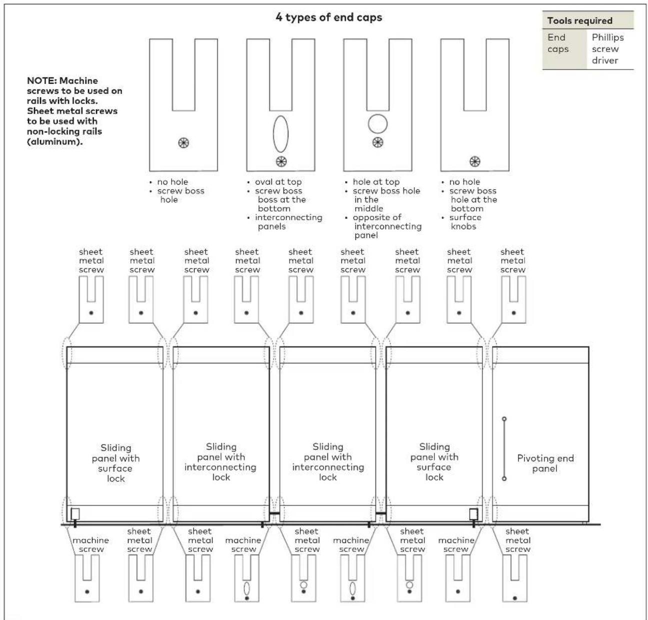
7.7.1 Select the appropriate end cap for the rail.
7.8 Secure the end caps
Fig 50
![Tools required End caps Phillips screw driver, utility knife Trim tabs here for 1/2" [13] glass only. Bottom rail End cap bumper End cap Top rail End cap End cap bumper](/content/2026/05/828239/images/7cb48c60125a1705f4568dd74b0273201ae3604f18357180fa61458074e54239.jpg)
7.8.1 Install end cap. 7.8.2 Slide end cap bumper company into face of
each end cap.
NOTE: For 1/2" [13] glass, trim tabs on back of logo cap.
- HSW-ES Sliding Glass Walls
- Easy Safe
- Installation instructions
- Table of contents
- Technical specifications 3
- Installation instructions - Prepare track 8
- Installation instructions - DA & SA pivoting end panel 16
- Installation instructions - Sliding panel 24
- Installation instructions - Double-action sliding panel with ITS96 28
- Installation instructions - Fixed panel door 39
- Installation instructions - Alignment, covers, end caps, miscellaneous 45
- Technical specifications
- Overview
- Ceiling mount
- General information
- Intended use
- Glass requirements/fittings/mounting
- Requirements for glass panel
- Safety instructions
- Symbols used - Safety/Installation
- CAUTION
- WARNING
- TIPS AND RECOMMENDATIONS
- CLOSING EDGE OF DOOR
- Maintenance, care, repair
- Disposal
- Specification - technical data
- Tempered laminate glass (TLG) and adhesive specifications
- NOTE: Door glass should not be installed until the full cure time has been reached (see chart above).
- Tools required
- Installation options/Overall top of door components
- Installation in the carrier profile
- Installation options/Bottom of door components
- Installation options/Bottom of door components (continued)
- Installation instructions - Prepare track
- Determine the track arrangement
- FIRST determine the following:
- Note direction which doors will travel:
- Install single-action pivoting end panel retaining clip
- NOTE:
- Install door track stop in stacking area
- Installing the track
- NOTE: REVISION PIECE IS INSTALLED IN STEP 2.7.
- Installing upper pivot block
- Install rollers in track
- NOTE: ENSURE TRACK IS CLEAN OF SOLID DEBRIS AND GREASE.
- Install revision piece
- Prepare the roller pattern in the track
- Installation instructions - DA & SA pivoting end panel
- Preparing the DA & SA pivoting end panel (with monolithic glass only)
- Preparing the DA & SA pivoting end panel (with tempered laminated glass only)
- Preparing the upper pivot block
- Install floor pivot or BTS80 closer
- Install pivot into end panel carrier profile
- Install top cover gasket
- Installing top covers
- Install DA & SA pivoting end panel into track
- Secure end panel in track
- Slide retaining clip inside track groove and tap/snap into place around upper pivot pin.
- Installation instructions - Sliding panel
- Preparing the sliding panel (with monolithic glass only)
- Preparing the sliding panel (with tempered laminated glass only)
- Install sliding panel onto rollers and adjust door height
- Install gasket and top cover
- Installation instructions - Double-action sliding panel with ITS96
- Preparing the DA sliding panel (with monolithic glass)
- Preparing the DA sliding panel
- (with tempered laminated glass only)
- Installing three piece lock
- Prep for installing two piece lock (when required)
- Install top cover and carrier profile gaskets
- Installing three piece lock (continued)
- Install two piece lock (continued)
- Installing DA sliding panels onto rollers and adjust door height
- Secure three piece lock to track
- Secure two piece lock to track
- ITS96 closer adjustment
- Adjust deadstop:
- Adjust sweep and latch:
- ITS96 hold open (optional) and spring force adjustment
- Installation instructions - Fixed panel door
- Preparing the fixed panel door (with monolithic glass only)
- Preparing the fixed panel door (with tempered laminated glass only)
- Installing the fixed panel holders
- Installing the saddle and fixed panel door
- Adjusting and securing fixed panel door
- Install gasket and top cover
- Installation instructions - Alignment, covers, end caps, miscellaneous
- Aligning panels into stacking area
- Aligning panels side by side in straight run
- Slide panels into place along straight run of track.
- Secure carrier profile file connecting inserts and end caps
- Drilling for ES locking bolt strike
- Secure bottom rail covers and rail lock preparation
- If using surface lock:
- NOTE: Ensure surface bolt is in down position.
- If using mortise lock:
- Installing the brush
- Carrier profile brush:
- Bottom brush:
- Selecting the proper end cap
- Secure the end caps
Brand : Dormakaba
Model : HSW-ES
Category : Sliding door