
HYBC5080AV - Débroussailleuse à neige HYUNDAI - Free user manual and instructions
Find the device manual for free HYBC5080AV HYUNDAI in PDF.

| Product Type | Snow Thrower |
| Brand | Hyundai |
| Model | HYBC5080AV |
| Clearing Width | 20 inches (51 cm) |
| Intake Height | 10 inches (25 cm) |
| Weight | 35 lbs (15.9 kg) |
| Dimensions (L x W x H) | 45 x 21 x 32 inches |
| Power Source | Electric Corded |
| Motor Power | 13.5 Amps / 1800 Watts |
| Chute Rotation | 180 degrees manual |
| Chute Direction Control | Pivot lever |
| Auger Type | Plastic with rubber blades |
| Throw Distance | Up to 30 feet |
| Wheel Size | 7 inches |
| Handle Type | Foldable for storage |
| Safety Features | Safety switch, emergency stop button |
| Maintenance | Clean after use, lubricate auger, inspect cord |
| Spare Parts Available | Auger blades, chute assembly, belts, wheels |
| Warranty | 2 years limited |
| Recommended Use | Light to moderate snow on walkways and driveways |
Frequently Asked Questions - HYBC5080AV HYUNDAI
User questions about HYBC5080AV HYUNDAI
0 question about this device. Answer the ones you know or ask your own.
Ask a new question about this device
Download the instructions for your Débroussailleuse à neige in PDF format for free! Find your manual HYBC5080AV - HYUNDAI and take your electronic device back in hand. On this page are published all the documents necessary for the use of your device. HYBC5080AV by HYUNDAI.
USER MANUAL HYBC5080AV HYUNDAI
natural_image
Technical line drawing of a mechanical device with articulated arms and a base mount (no text or symbols)CONTENTS
- SAFETY 4 - 7
- QUICK START 8 - 18
- STARTING PROCEDURE 19 - 21
- STOPPING PROCEDURE 21
- USING THE MACHINE 22 - 23
- MAINTENANCE 24 - 27
- TROUBLESHOOTING 28
- SPECIFICATION 29
- PART LOCATIONS 30
- DECLARATIONS OF CONFORMITY 31
- RECYCLING & PRODUCT DISPOSAL 32
- CONTACT DETAILS 32
- MANUAL UPDATES 32
- WARRANTY 33
1. SAFETY
1.1. General safety notes.
1.1.1. The operator of the machine is responsible for, and has a duty of care in making sure that the machine is operated safely and in accordance with the instrucons in this user manual. Keep the manual safe and pass it on if the machine is loaned or sold to another user.
1.1.2. Please note the following safety points.
1.1.2.1. The machine should never be le it in a condion which would allow an untrained or unauthorised person/s to operate this machine.
1.1.2.1.1. All due care and diligence should be taken by the operator for the safety of, and with regard to, those around whilst using the machine.
1.1.2.1.2. Some or all of the following - warning signs, symbols and/or PPE pictograms may appear throughout this manual. You MUST adhere to their warning/s. Failure to do so may result in personal injury to yourself or those around you.

DANGER
Indicates a hazard, which, if not avoided, could result in serious injury or death.

WARNING
Indicates a hazard, which, if not avoided, could result in serious injury.

CAUTION
Indicates a hazard which, if not avoided, might result in minor or moderate injury.

NOTE
Indicates a situaon that could easily result in equipment damage.

READ and keep the manual safe and pass it on if the machine is loaned or sold to another user. You MUST fully read instrucons to make sure you use and operate machine safely.
Appropriate Personal Protective Equipment (PPE), MUST be worn at all mes when machine is in use or being repaired.

1.2. Carbon monoxide (where applicable).

1.2.1. Carbon monoxide is a colourless and odourless gas. Inhaling this gas can cause death as well as serious long term health problems such as brain damage.
1.2.2. The symptoms of carbon monoxide poisoning can include but are not limited to the following; Headaches, dizziness, nausea, breathlessness, collapsing or loss of consciousness.
1.2.2.1. Carbon monoxide poisoning symptoms are similar to u, food poisoning, viral infecons and simply redness. It is quite common for people to mistake this very dangerous poisoning for something else.
1.2.2.2. To avoid carbon monoxide poisoning DO NOT use Petrol/Diesel-powered equipment inside any of the following; Home, garage, tent, camper van, mobile home, caravan or boat.
This list is not exhaustive and if you are in any doubt contact your dealer.
1.2.3. If you think you have or someone around you has been aected by carbon monoxide poisoning;
1.2.3.1. Get them fresh air immediately, by leaving the aected area or by opening doors and windows. If safe and praccal to do so make sure that the machine is turned o. DO NOT enter a room you suspect of having carbon monoxide present – instead call the emergency services.
1.2.3.2. Contact a doctor immediately or go to hospital - let them know that you suspect carbon monoxide poisoning.
1.2.4 DO NOT use in an enclosed area or a moving vehicle.
1.3. General fuel safety (where applicable).

CAUTION
ALL FUELS ARE FLAMMABLE
1.3.1. Fire hazard - keep fuel away from all sources of ignition for example heaters, lamps, sparks from grinding or welding.

Fire Hazard
1.3.2. DO NOT carry out hot work on tanks that have contained fuel it is extremely dangerous.
1.3.3. ALWAYS keep work area clean and dy.
1.3.4. ALWAYS clean up all spills promptly using correct methods i.e. absorbent granules and a lidded bin.
1.3.5. ALWAYS dispose of waste fuels correctly.
1.4. Fuelling/De-fuelling (where applicable).

CAUTION
ALL FUELS ARE FLAMMABLE
1.4.1. ALWAYS fuel and defuel in a well-venlated area outside of buildings.
1.4.2. ALWAYS wear correct, suitable and t for purpose Personal Protective Equipment (PPE), suggested items are but not limited to safety gloves and overalls.

1.4.3. When fuelling/de-fuelling ALWAYS avoid inhaling fumes
1.4.4. When de-fuelling ALWAYS use a propriety fuel retriever.
1.4.5. ALWAYS carry fuel in the correct and clearly marked container.

Fire Hazard
1.5. Electrical safety (where applicable).

Risk of electric shock
1.5.1. Electricity can kill - NEVER work on LIVE/ENERGISED equipment.
1.5.2. Prior to carrying out any maintenance work you MUST Identify electrical isolation methods and isolate all electrical supplies,
1.5.3. Prior to use and with all electrical supplies isolated You MUST check all electrical cables, plugs and connecons for the following;
1.5.3.1. Are intact and have no signs of damage, to include but not limited to bare wires, chang, cuts and loose wiring.
1.5.3.2. If there are any signs of damage, the damaged item MUST be taken out of service until the damage has been repaired by an electrically competent person.
1.5.3.3. All trailing cables should be routed so as not to cause any kind of trip hazard.
1.5.3.4. NEVER work on or near electricity with wet hands, wet clothing, and wet gloves.
1.6. Baeries (where present).

Corrosive
1.6.1. Baeries present a risk if they become damaged by the possible leaking of electrolyte. This electrolyte is an acid and can cause serious burn injuries. Care should be taken
when working on or near them. NOTE the electrolyte may be in liquid or gel form.
1.6.2. Should you come into contact with electrolyte you should;
1.6.2.1. Remove all clothing contaminated with electrolyte. If you cannot remove then saturate in water.
1.6.2.2. Get medical assistance as soon as possible. You must advise the medical sta of the type acid.
1.6.2.2.1. Lead/acid baery = dilute sulphuric acid
1.6.2.2.2. Nickel/cadmium = potassium hydroxide alkali electrolyte.
1.6.2.3. Use fresh running water to wash o excess electrolyte, connue this unl medical assistance arrives. Make sure that you do not wash the electrolyte to another part of the face or body.
1.6.2.4. If electrolyte comes into contact with Eyes the electrolyte needs to be immediately washed away with large amounts of water. Make sure that you do not wash the electrolyte to another part of the face or body.
1.6.3. Gasses from charging baeries are highly ammable and great care should be taken to charge in well venlated areas.
1.6.4. There is an explosion risk if the baery terminals are short circuited, when connecng/dis-connecng ALWAYS exercise great care so that the terminals or baery leads are NOT allowed to touch and cause a spark. ALWAYS use suitable insulated tools.

Risk of explosion
1.7. Vibraons (where applicable).
1.7.1. Prolonged use of hand held (operated) machines will cause the user to feel the eects of/from vibraons. These vibraons can lead to white nger (Raynaud's phenomenon) or carpal tunnel syndrome. This condion
reduces the ability of the hand to feel and regulate temperature, causing numbness and heat sensaons and may cause nerve damage and circulatory issue death.
1.7.2. Not all factors that lead to white nger disease are known, but cold weather, smoking and other diseases that aect blood vessels and blood circulaon as well as large and long-lasng impact of shocks are considered factors in the formaon of white nger. Note the following to reduce the risk the white nger and carpal tunnel syndrome:
1.7.2.1. Wear gloves and keep your hands warm
1.7.2.2. Take regular breaks
1.7.3. All of the above precautions may help reduce the risk of white nger disease but not rule out carpal tunnel syndrome. Long-term and regular users are therefore recommended to observe the condition of your hands and ngers. Seek medical aenon immediately if any of the above symptoms should occur.
1.8. Noise (where applicable).
1.8.1. The operang noise of the machine can damage your hearing. Wear hearing protecon such as earplugs or ear defenders to protect your hearing. Long-term and regular users are advised to have hearing checked regularly. Be especially vigilant and cauous when wearing hearing protecon because your ability to hear alarm warnings will be reduced.
1.8.2. Noise emissions for this equipment is unavoidable. Carry out noisy work at approved mes and for certain periods. Limit the working me to a minimum. For your personal protecon and protecon of people working nearby it is also advisable for them to wear hearing protecon.
1.8.3. See CERTIFICATE of CONFORMITY secon for Outdoor Noise declaraon of conformity.

1.9. Additional safety labels.
Keep all children, bystanders and helpers 15 meters from the machine.

Warning against ying objects wear helmet, goggles and ear protecon.

Warning: Danger from hot components, especially exhaust - Keep clear of combustible materials.

1.10. Additional safety instrucons.
1.10.1. Spectators should be told how to correctly aract the operator's aenon, otherwise it could create an unsafe situaon.
1.10.2. Never touch either the nylon cung head or the metal cung blade whilst the machine is in use – You MUST allow the machine to come to a stop and to remove the HT lead before carrying out any maintenance.
1.10.3. During and aer use the engine and exhaust will be very HOT you must keep all your all parts of your body and clothing including all combustible materials clear of the engine and exhaust.
1.10.4. DO NOT use the machine during or aer rain, snow or sleet. The oor will become slippery. DO NOT use the machine on a slope or uneven ground or if there is the chance of slipping or losing the stability.
1.10.5. If you trip or fall whilst machine is in use you MUST immediately release the throle, and turn o the ignition switch.
1.10.6. If you hit any obstacles you must stop the machine and remove the HT lead so that you can inspect the machine. IF the machine is
damaged in any way you MUST get it repaired before restarng work.
1.10.7. DO NOT use the machine with a blunt, cracked or damaged cuer blade.
1.10.8. When using the blade cuer there is a danger of kickback. Kickback is a reacon that can occur when the rotang cung blade strikes an object which cannot be cut. This contact causes the cung blade to stop for an instant and then suddenly repel from the object taken with accelerated force. This reacon can be violent enough that the operator momentary loses control of the machine. A kickback can occur without warning when the cuer encounters an unseen obstacle when the blade is running. This is more likely in areas where it is dicult to properly check the material/area to be cut. For easy and safe cung, cut the weeds/brush from right to your le.
1.10.9. If any trimmed materials get tangled in the nylon cord or cung blade you MUST stop the machine and remove the HT lead. Onley then can you clear any blockages.
1.10.10. ⚠️ DANGER
NEVER use the machine with a saw blade aachment it is STRICTLY FORBIDDEN.
1.10.11. DO not use the brush cuer for trimming trees.
1.10.12. DO NOT wear rings and jewelry or loose, dangling clothing that could get caught in the machine. DO NOT wear footwear with unprotected toes and DO NOT work barefoot or without leg protecon. In certain situations, you have to wear head protecon.
2. QUICK START
You can also check out our online video at www.youtube.com/hyundaipowerequi
2.1. This guide is meant to serve as a quick reference for operang your Hyundai brush cuer It is for convenience and the user should read the safety secon rst.
OUTDOOR USE ONLY.
This brush-cuer produces carbon monoxide - a poisonous, colourless & odourless gas that can cause death or serious injury. Petrol is highly ammable, always handle with extreme care and in a well venlated area.
Always remove HT lead from spark plug when checking machine or changing parts.
2.2. This product includes:
Main unit, Operators handle, Trimmer head, Bump feed nylon trimmer head, 3 tooth steel blade, 5 tooth steel blade, Spare 2.5 mm nylon cord, Full harness, Gloves, Face shield, Ear defenders, Tool kit, Spare Bosch spark plug, 2-Stroke oil mixing bole, User manual.
2.3. At this point, check that you have all of the included items listed above. If any are missing or damaged, call 01646 687 880 or email info@hyundaipowerproducts.co.uk.
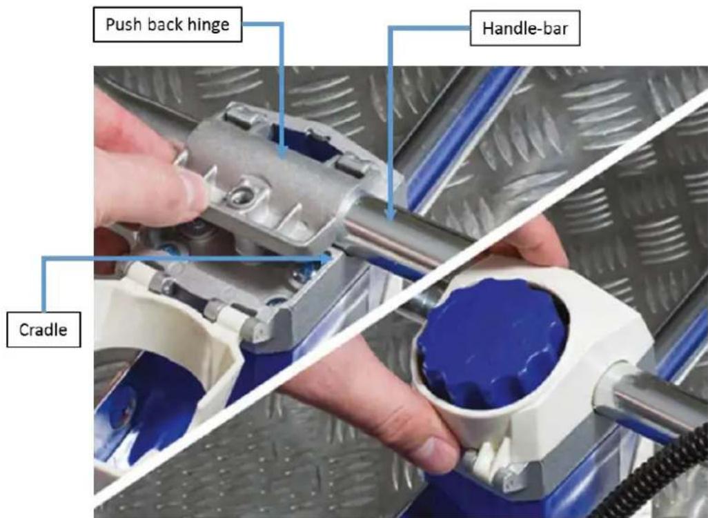
2.4. Handle assembly.
Remove the nut and bolt from the trigger with the supplied Allen key. Place the trigger onto the handle. Align the holes on trigger with hole on the handle pole. Insert the nut and bolt and ghten.
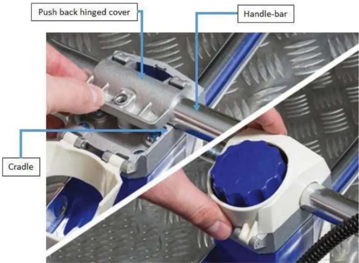
Li the White cover unscrew and remove the hand-wheel.
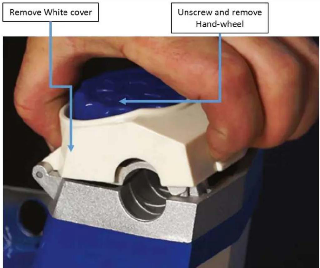
Push back the hinged cover, place the handle into the cradle, push hinge back over the handle-bar and lock into place using the hand-wheel. Push the White cover back into posion.
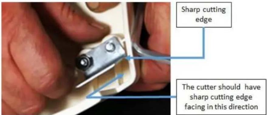
2.5. Trimmer blade assembly.
Place the two bolts through the guard from the top.
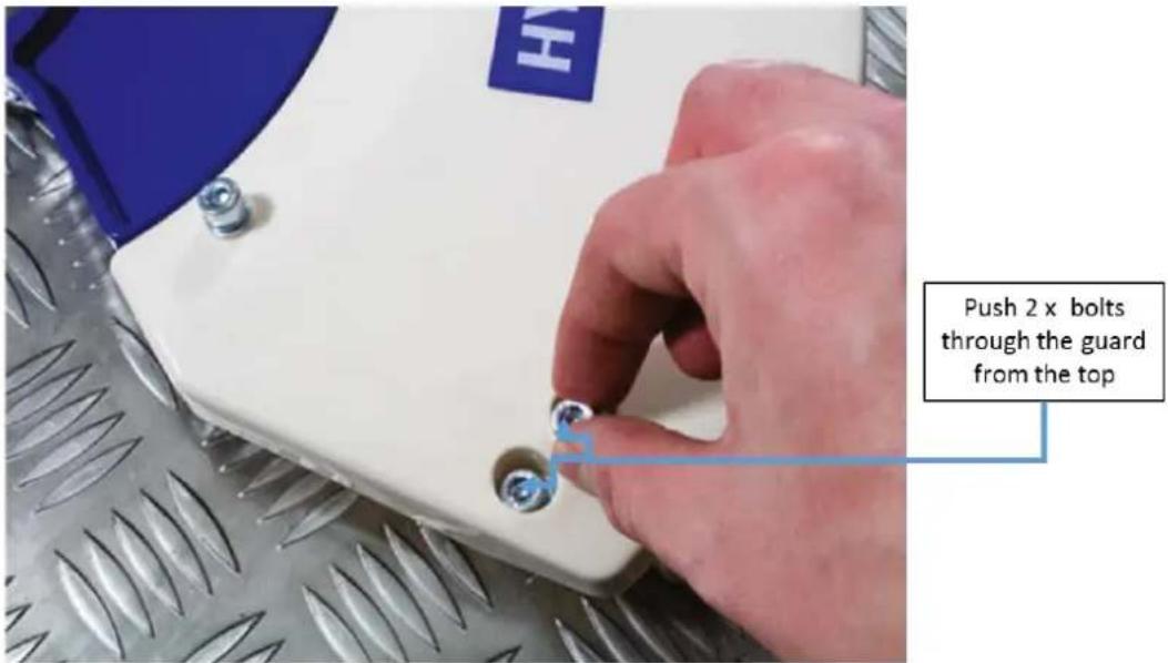
On the underside of guard place the cuer over the bolts and secure in places using the 2 nuts. Tighten by using Allen key and spanner.

The cord cuer blade should have sharp cung edge facing in direcon shown in image below. If the blade is not mounted correctly it will not cut the cord at the correct length.
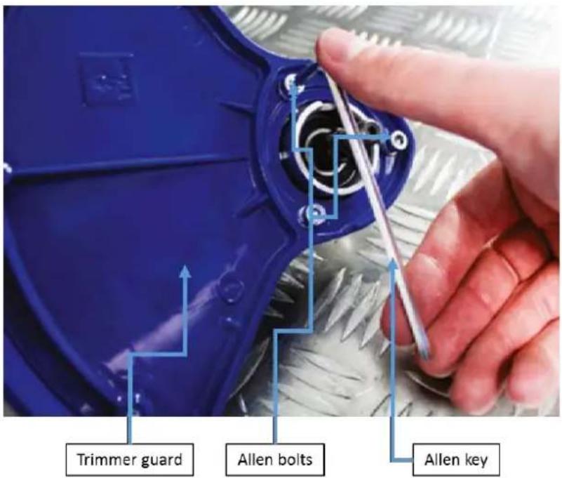
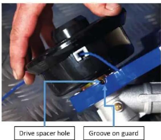
2.6. Guard assembly.
Remove in this order - lock-nut, stainless steel cover, spacer and drive spacer.
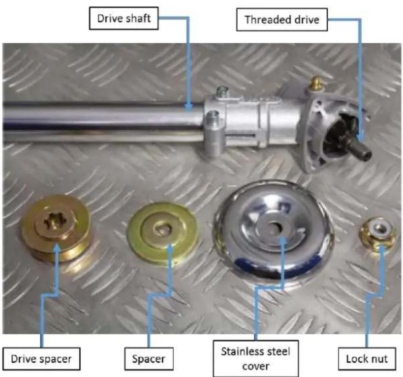
Place trimmer guard over threaded drive, align the three holes and secure in place using the 3 Allen bolts. Tighten in place using the Allen key.
2.7. Grass trimmer assembly. (Bump trimmer head).
Place the drive spacer over the threaded drive. Then each the trimmer head onto the threaded drive - ghten in an an-clockwise direcon.
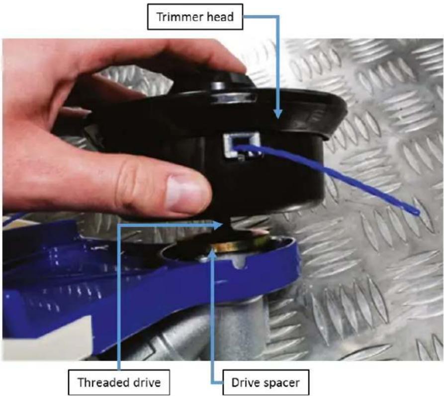
Align hole on drive spacer with groove on the guard, then using the Allen key lock the sha in place – once sha is locked you can ghten the trimmer head.

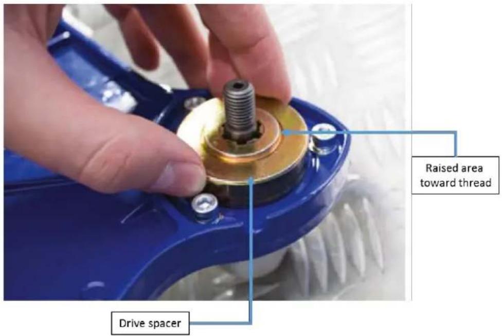
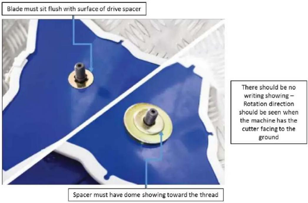
2.8. Cung blade assembly. (Instrucon to suit either 3 or 5 bladed cuer).
Place the drive spacer over the threaded drive - N.B. Raised area to be toward the thread
Place the over the threaded drive, then place spacer over threaded drive—N.B. Raised area to be toward the thread. N.B. There should be now wring showing.
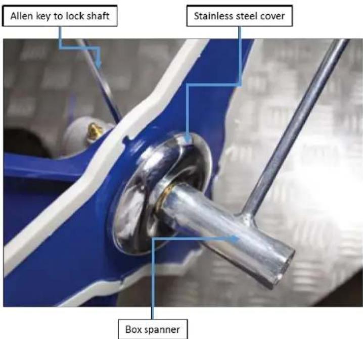
Once blade is in place, put the stainless steel cover over the spacer, put lock-nut onto threaded shaft and loosely ghten (an-clockwise direcon). Use the box spanner to over the lock-nut and tighten – use the Allen key to lock the sha.
2.9. Drive sha assembly.
Remove the rubber plug from the end of the sha—Loosen the hand wheel then push the two shas together and rotate unl they click into placed. Once locked into place ghten the hand wheel. To release sha undo hand wheel then press release lever.

2.10. Fing/replacing spool line.
Squeeze the bump head unit either side on the grooves and pull to remove the top of the head. Remove the spool, spring and washer from the spindle.

natural_image
Close-up of hands holding a black electronic device with blue arrows indicating motion or force direction (no text or symbols visible)Squeeze head and remove top of head
With the bump feed facing outwards from your le hand, take the looped end and place it around the holder in the middle of the spool as shown below. You will need approximately 3 metres of 2.5 mm of nylon cord
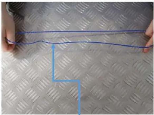
natural_image
Close-up of hands holding a blue wire on a diamond-patterned surface, with a blue arrow pointing downward (no text or symbols)Take cutting line and fold in half

natural_image
Close-up of hands holding a black mechanical component with blue wiring, no visible text or symbolsPlace the looped end over the spool
Wrap the nylon cord around the spool in an an-clockwise direcon unl you have approximately - 150 mm (6"). Then insert spool back into the spindle. Feed the line through the two notches in the spindle and reinsert the washer and spring into the spool. Once complete re-aach the spindle to the cung head.

natural_image
Close-up of hands tying a blue cable with a wire, no visible text or symbolsWrap the nylon cord around the spool in an anti-clockwise direction until you have approximately - 150 mm (6").

natural_image
Close-up of hands assembling a mechanical component with blue arrows indicating assembly (no text or symbols visible)Then insert spool back into the spindle. Feed the line through the two notches in the spindle.

natural_image
Close-up of hands holding a mechanical component with blue wires and a blue cap, no visible text or symbolsReinsert the washer and spring into the spool. Once complete re-attach the spindle to the cutting head.
2.11. Face mask assembly.
Rotate to align the tags on the helmet to match the holes on the top of the visor. Place the visor over the tags, then rotate the tags 180^ to secure into place. Place the ear defenders over the outside of the headband on the helmet and place into the clips.

2.12. Mixing two stroke oil.
Fill the mixing bole with fresh unleaded petrol to the fuel level line. For the rst II use the rao of 25:1 thereaer use a rao of 40:1.

2.13. Adding fuel.
Unscrew the fuel tank cap and carefully add a fuel/2 stroke oil mixture as in secon 2.12. DO NOT overll and allow a 25 mm gap at the top of the tank. Once full replace and correctly ghten the fuel cap.
DO NOT use straight unleaded petrol.

natural_image
Close-up of a hand pressing down on a blue plastic bottle with blue arrows indicating motion (no text or symbols visible)Remove fuel cap
Fill with a Fuel/Oil mixture
3. STARTING PROCEDURE
Fill with fuel/oil mixture, make sure the fuel cap is secure. - Set the ignition switch on the handle to the ON posion.

Pump the primer bulb several mes unl fuel shows in the bulb.
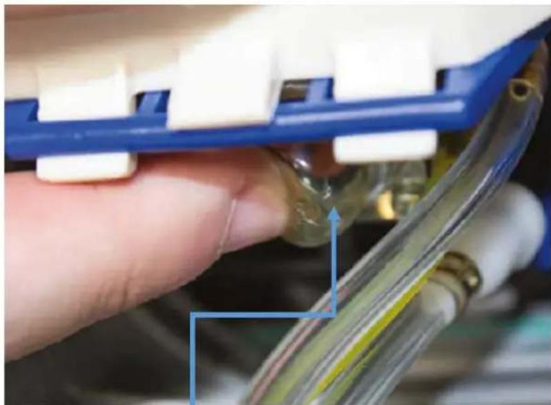
natural_image
Close-up of a hand holding a blue plastic electrical connector with white connectors, partially connected to a transparent cable or wiring (no visible text or symbols)Primer bulb
For COLD start set the choke lever to the ON posion by moving upwards as shown. For a WARM start keep the choke lever at the OFF posion.

Place one hand on the machine, and using the other hand pull the recoil until you feel a resistance, then pull briskly. Repeat until machine starts. When the machine starts move the choke to the OFF position. DO NOT let go of the recoil handle instead allow the recoil cord and handle return slowly.

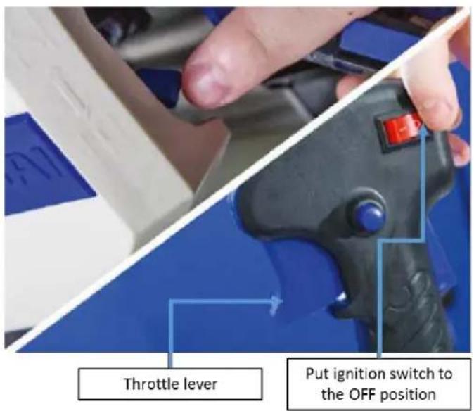
Once the engine has started press the throle lever and throle safety together. This will accelerate the machine to cung speed. To lock the throle press the throle lock button.
To release the throle lock lightly press the throle lever.

4. STOPPING PROCEDURE
4.1. Before stopping the machine allow the engine to cool down for a few minutes, by allowing it to run without throle.
4.2. You MUST allow the cung head to come to a full stop before carrying out any maintenance on the machine.
To STOP the machine release the throle lever and move the ignition switch to the OFF posion. If not already in OFF posion move the choke to the OFF posion.
5. USING THE MACHINE
5.1. Before starng work.
5.1.1. YOU MUST check the work area for obstacles such as stones, metal rods or other objects. If these cannot be removed, mark these posions, so you can avoid contact with the trimmer head and objects. Overhead power lines can be caught on the blade head if machine is swirled in the air.
5.2. Accessories.
5.2.1. Make sure that your product is only equipped with original accessories. Only use the machine with original parts which are specied by the manufacturer. The use of any other accessories may cause injury to the user and damage to the machine.
5.3. Wearing the shoulder harness.

CAUTION
When you use this machine always wear the provided harness.
Make sure that the machine is securely hooked onto the strap.
If you do not, you will not be able to control the machine safely.
This may result in injury to yourself or other people.
Never use a harness with any type of defect especially with a defective quick release mechanism.
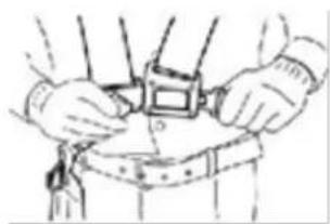
a. Put the hraness on.

natural_image
Line drawing of a person in a safety vest and helmet, saluting (no text or symbols)b. Connect quick release buckle
natural_image
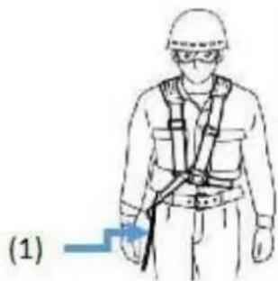
Illustration of hands adjusting a belt or belt device (no text or symbols visible)c. 1 = Protector Shield and machine hook.
natural_image
Illustration of a person wearing a hard hat and safety harness, with a blue arrow pointing to the right side (no text or symbols present)d. Adjust the harness to suit user.

natural_image
Line drawing of a person wearing a hard hat and safety vest, using a handheld tool to measure a device (no text or symbols present)e. 1 = Quick release Harness buckle. Aach machine to harness hook.

f. The shoulder strap is ed with a quick release device (see image) ed. You can remove the shoulder strap quickly by pulling the quick release device.
5.4. Trimming techniques.

CAUTION
If you are not familiar with the trimming, pracce with the machine with the machine stopped.
5.4.1. Always trim or cut with the engine running at high speed.
5.4.2. Do not run the machine slowly except for when warming up before use or cooling down aer use.
5.4.3. Swing the nylon cung head of the trimmer horizontally from le to right.

natural_image
Illustration of a worker using a tool to clean or walk, with arrows indicating movement (no text or symbols)5.4.4. Keep cung deck parallel with the ground. Do not It the nylon cung or blade head during operaon.
5.4.5. For correct cung height trim a test area in advance.
5.4.6. Keep nylon cung or blade head at the same level for an even depth of cut.
5.4.7. Nylon trimming head is only to be used for cung grass.
5.4.8. Metal blade head is only to be used for brush only.
5.4.9. To prevent overheang NEVER over cut, instead cut o smaller lengths of grass or brush. You MUST also remove any tangled materials – You MUST stop the machine and remove the HT lead before carrying out this task.
natural_image
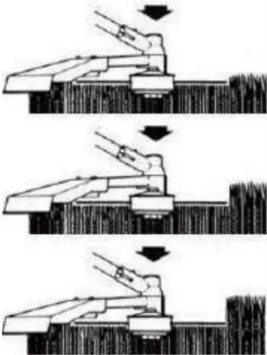
Three-panel diagram showing a robotic arm performing a manual press operation, with arrows indicating motion direction (no text or symbols)5.4.10. When trimming around trees trim slowly making sure that the nylon cord does not come into contact with the trunk. Walk around the tree from le to right and approach grass with the p of the cung nylon cord.
5.4.11. To release more nylon cung cord run the machine at full throle and tap the nylon cung head on the grass. The nylon cord is then released. Any excess cord is cut o by the trimmer blade mounted on the guard. When trimming near brick or stone walls the nylon cord will wear out quicker.
6. MAINTENANCE

WARNING
Always stop the engine and unplug the spark plug before doing any repairs or maintenance.
Never touch the rotang nylon cord or blade.
Check and maintain fuel level regularly, and maintain the fuel/oil mix to the correct rao.
Frequently check the brush cuer and make sure that all grass deposits are removed from the trimmer head and/or blade
Check the blade, in order to obtain a good cut, the blade should always be sharp and well balanced. At regular intervals, check the ghtness of all nuts, bolts and screws.
If the blade hits an obstacle check for damage and if the machine vibrates badly stop the lawnmower and take it to a service dealer.

CAUTION
Always refuel in a well-venlated area with the engine o.
Whilst carrying out maintenance you must wear appropriate Personal Protective Equipment (PPE). Suggested PPE Sturdy footwear, work gloves (especially when working near blade), long trousers and hearing protecon.
| Component | Each use | Every 3 mths or 15 hours | Every 6 mths or 50 hours | Every 12 mths or 100 hours | Every 24 mths or 300 hours | |
| Air Iter | Check | ○ | ||||
| Clean | ○ a | |||||
| Sparkplug | Check/Adjust | ○ | ||||
| Change | ○ | |||||
| Sparkplug electrode | Clean | ○ | ||||
| Cooling ns | Check/Clean | ○ | ||||
| Connecons – nuts bolts screws etc. | Check and ghten as required | ○ | ||||
| Coupling | Examine | ○ b | ||||
| Idle | Check/Adjust | ○ b | ||||
| Valve clearance | Check/Adjust | ○ b | ||||
| Spark arrester | Check/Clean | Every 300hours | ||||
| Fuel tank | Examine | ○ | ||||
| Fuel pipes | Examine | Each use replace as required | ||||
| Bevel gear | Fill | Aer 25 hours of use (For locaon of bevel gear grease nipple Secon 9 Part Locaon. | ||||
a = Increase maintenance intervals if operang in dusty environments. b = All maintenance operaons - except those listed in the operang instrucons, must be performed by qualified service personnel
6.1. Air Iter.

CAUTION
Never let the engine run without the air lter. A dirty air aects the engine performance, increases fuel consumpon and makes it dicult to start. If you noce a loss of engine power.
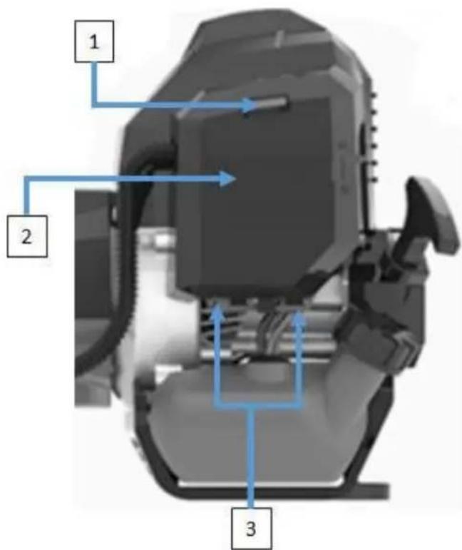
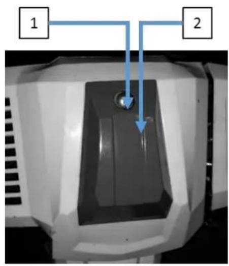
6.1.1. Push clip (1) down and pull Iter cover (2) away from machine, take care to release lower clips (3).
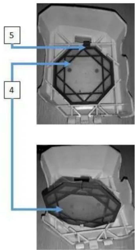
6.1.2. Remove the Iter (4) by pressing clip (5) and liing Iter clear.
6.1.3. Wash with soap and water. Never use petrol or benzene!
6.1.4. You MUST allow the Iter to fully air dry before replacing it on the machine.
6.1.5. To replace the iter reverse the above process.
6.2. Spark plug.

WARNING
The spark plug MUST be fully ghtened otherwise the engine will overheat causing damage. Always complete the following steps aer the engine has been turned o and allowed to cool down.
6.2.1. To make sure the engine runs correctly a spark plug gap of 0.6 -0.7 mm must be maintained and the spark plug must be free of carbon deposits.
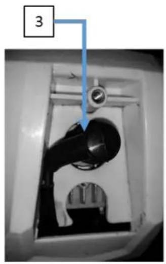
6.2.2. Undo retaining screw (1) and li spark plug cover (2) clear.
6.2.3. Disconnect the spark plug cap (3) carefully. Do not pull on the HT lead instead pull on the spark plug cap (3).
6.2.4. Using the supplied spark plug wrench unscrew the spark plug (4) in an an-clockwise direcon.
6.2.5. Check the spark plug (4) visually for damage and electrode wear, remove the carbon deposits.
6.2.6. Check the gap with a feeler gauge and adjust electrode at the correct gap of 0.6 -0.7 mm.
6.2.7. Check the washer (replace as required) of the spark plug. Ret the spark plug by hand to make sure it does not cross thread, ghten the spark plug to a torque of 12/15Nm.
6.2.8. Ret the spark plug cap onto the spark plug.
natural_image
Close-up of a mechanical component with a blue arrow pointing to part 3 (no visible text or symbols)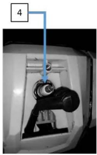
natural_image
Close-up of a mechanical component with a blue arrow pointing to a numbered label '4' (no readable text or symbols beyond the number)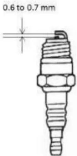
6.3. Trimmer blade sharpening.

WARNING
When sharpening the blade you MUST wear safety gloves.
6.3.1. Remove the cung blade (2) from the shield (1).
6.3.2. Put cung blade securely into a vice.
6.3.3. Sharpen the blade with a suitable at le.
6.3.4. Please make sure that you maintain the angle of cung. Maintain the original cung angle.

6.4. Storage.

WARNING
If you do not follow these steps, deposit may arise in the carburetor. This will cause starng dicules and may cause permanent damage.
6.4.1. Perform all the general maintenance that the maintenance secon of your 'User Manual' is recommended.
6.4.2. Clean the outside of the machine, drive axle, shield and nylon cung head.
6.4.3. Remove all fuel from the fuel tank.
6.4.4. Aer all the fuel is drained, start the engine.
6.4.5. Allow the engine to run in idle unl engine stops alone. This allows the fuel to be removed from the carburetor.
6.4.6. Allow engine to cool down (about 5 minutes).
6.4.7. Use a spark plug wrench, remove the spark plug.
6.4.8. Pour 1 teaspoon of clean 2-cycle oil into the combuston chamber. Slowly pull the starter rope several mes to coat internal components. Replace the spark plug.
6.4.9. Store the machine in a cool, dry place away from any source of ignition such as an oil burner, water heater etc.
6.5. Transporting the machine.
6.5.1. When transporng the machine make sure that no fuel is allowed to leak out.
6.5.2. DO NOT allow the trimmer/brush cuer come into contact with persons, animals and property.
7. TROUBLESHOOTING

CAUTION
7.1. If troublesomeong does not solve the problem, contact your dealer or the manufacturer directly. Use only original parts approved by the manufacturer, otherwise a hazard risk arises.
NO SPARK.
Possible causes;
- Carbon deposit between electrodes of the spark plug.
- Ignion coil defecve ywheel magneto too weak.
Possible correcve acons;
- Clean the spark plug. Adjust the gap to 0.6\~
0.7mm, Replace the spark plug. - Replace the Ignion coil or the ywheel.
WEAK SPARK.
Possible causes;
- Too much fuel in the combuston chamber, poor fuel or water in tank.
- Blocked fuel line
Possible correcve acons;
- Remove spark plug and dry, replace fuel.
- Clean the carburetor and clean the lines.
NORMAL FUEL SUPPLY BUT WEAK COMPRESSION
Possible causes;
- Worn piston rings, spark plug not ghtened, the cylinder head is not ghtly wrong valve clearance or ignition.
Possible correcve acons;
- Replace or adjust.
NORMAL FUEL SUPPLY AND POOR SPARK
Possible causes;
- Poor contact between spark plug cap and spark plug.
Possible correcve acons;
- Check or exchange.
MOTOR DOES NOT COME UP TO SPEED
Possible causes;
- Choke is in "cold start" posion, exhaust system does not clog air supply, worn Movable elements, spark weak, valve clearance to big, sooty cylinder head.
Possible correcve acons;
- Open choke, exhaust system ignition coil exchange check or replace ywheel Adjust spark plug.
POWER RUNS OUT
Possible causes;
- Congested fuel lines to the carburetor. Spark plug gap incorrect.
Possible correcve acons;
- Unblock/Replace fuel lines and carburetor. Reset spark plug gap.
NOISY ENGINE
Possible causes;
- Incorrect choke lever posion, or damage to cranksha.
Possible correcve acons;
- Check and correct choke lever posion. Check and/or replace cranksha.
LEAKING CARBURETOR
Possible causes;
- Failure of the non-return valve on the fuel tank lid. Worn carburetor gasket.
Possible correcve acons;
- Replace the fuel cap. Replace the carburetor seal.
8. SPECIFICATION.
| MODEL | HYBC5080AV | |
| ENGINE | Engine type | Single cylinder, 2 stroke, air cooled. |
| Engine size - cc | 50.8 | |
| Fuel tank capacity - ml | 800 | |
| Noise level dB (A) | 115 | |
| Max speed - rpm | 7500 | |
| Power - kw | 1.56 | |
| Start method | Recoil | |
| Fuel type/rao | Fresh unleaded petrol mixed with Semi-synthec 2 Stroke oil rst use rao 25:1 - thereaer use rao of 40:1 | |
| Drive type | Centrifugal clutch | |
| MACHINE | Bevel gear - grease type/qty ml | High temperature gear grease/25 |
| Head line length/diameter - mm | 3000/2.5 | |
| Cung width mm /length mm /diameter mm | 255mm for cuer blade / 400-450 for cuer head (Blade 1.6mm/3T | |
| Gross weight - kg | 13.68 | |
| Dry weight kg | 9.68 | |
| Fully assembled dimensions L x W x H - mm | 1820 x 750 x 500 |
9. PART LOCATIONS.

flowchart
graph TD
    A["Grass trimmer"] --> B["Brush cutter"]
    B --> C["Cord cutter"]
    C --> D["Gear case"]
    D --> E["Trimmer shield"]
    E --> F["Drive shaft"]
    F --> G["Shelf release lever"]
    G --> H["Hand wheel"]
    H --> I["Hand handle"]
    I --> J["Left handle"]
    J --> K["Throttle"]
    K --> L["Ignition switch"]
    L --> M["Throttle safety"]
    M --> N["Harness connection"]
    N --> O["Spark plug under cover"]
    O --> P["Air filter"]
    P --> Q["Fuel tank"]
    Q --> R["Primer bulb"]
    R --> S["Exhaust Warning HOT"]
    S --> T["Choke"]
    T --> U["Hand wheel"]
    U --> V["Hand release lever"]
10. DECLARATIONS OF CONFORMITY
EC Declaration of Conformity
We hereby declare that the machine detailed in this declaration complies to all the relevant provisions of the following EC directives.
• 2006/42/EC The Machinery Directive
• 2014/30/EU Annex II Electromagnetic Compatibility Directive
• 2016/1628/EC The Emission of Gaseous and Particulate Pollutants from internal Combustion engines
• 2000/14/EC Noise Emissions in the Environment by Equipment for use Outdoors.
And is in conformity with the applicable requirements of the following documents:
• EN ISO 11806-1:2011
• EN ISO 10517:2019
Declaration for 2000/14/EC Noise Emissions in the Environment by Equipment for use Outdoors.
Notified Body for EC Directive 2000/14/EC TÜV Rheinland (Shanghai) Co., Ltd.
| Model | Type | Engine Size | Measured Sound Power | Guaranteed Sound Power | Engine output |
| HYBC5080AV | Petrol Brushcutter | 50.8cc | 113.99dB(A) | 117dB(A) | 1.7kW |
Product Details
Brand : Hyundai
Model : HYBC5080AV
Description : Petrol Brushcutter
Name and address of technical documentation holder and EU distributor:
Genpower Ltd, Isaac Way, Pembroke Dock, Pembrokeshire, SA72 4RW, UK.
Signed by:

Roland Llewellin, Managing Director
Date : 21/04/2020
11. RECYCLING & PRODUCT DISPOSAL
11.1. We do not oer a takeback scheme for the recovery of Waste Electrical Electronic Equipment (WEEE) & Baeries instead the responsibility to dispose of WEEE and or Baeries is passed onto you by us. So when it becomes necessary to dispose of your machine you must take it to your local Civic
.1. Certain products contain WEEE waste which should not be disposed of in your domesc waste.

11.3.2. You MUST recycle WEEE in accordance with your local authority or recycling centre.
11.4. Baery recycling, certain products contain baeries which should not be disposed of in your domesc waste.

11.4.1. You MUST recycle baeries in accordance with your local authority or recycling centre.
11.5. Unwanted packaging materials should be sorted and taken to a recycling centre so it can be disposed of in a manner which is compatible with the environment.
11.6. The following symbol means that you should 'Reduce – Reuse – Recycle'.

11.7. We are a Member of the VALPAK Naonal Compliance scheme and our registraon number is RM08660
11.8. For further informaon about disposal please contact your Local Authority.
11.9. You can also get more advice and guidance about recycling at the following website hp://www.recycle-more.co.uk
Amenity Site. For further informaon please contact your Local Authority for disposal advice.
11.2. You MUST make sure that all unused oil and fuel is disposed of correctly either beforehand or at your local Civic Amenity Site. Under NO circumstance must any oil and fuel be put down any drains.
11.3. Waste Electrical Electronic Equipment (WEEE) recycling.
11.3
11.10. Should you pass this product onto another user either sold or loaned you MUST pass on this user manual. This will make sure that all other users can use and maintain the machine safely.

12. CONTACT DETAILS
POSTAL ADDRESS
Genpower Ltd, Isaac Way, London Road, Pembroke Dock, Pembrokeshire, SA72 4RW. UK.
TELEPHONE
+44 (0) 1646 687880
FAX
+44 (0) 1646 686198
TECHNICAL E-MAIL
aftersales@hyundaipowerproducts.co.uk
WEBSITE www.hyundaipowerproducts.co.uk
13. MANUAL UPDATES
13.1. Our manuals are constantly being reviewed and updated. Should you nd an error, omission or something you nd unclear please contact your dealer for assistance. E&OE.
13.2. Our latest manuals are also placed online.
13.3. We reserve the right to make any modicaons without prior noce whenever necessary.
14. WARRANTY
14.1. Proof of purchase will be required before you make a warranty claim.
Full warranty terms and conditions can be found on the HYUNDAI POWER PRODUCTS website:
www.hyundaipowerproducts.co.uk
Importer:
GENPOWER LTD
Isaac Way, London Road
Pembroke Dock, UNITED KINGDOM, SA72 4RW
T: +44 (0) 1646 687 880 F: +44 (0) 1646 686 198
E: info@hyundaipowerproducts.co.uk
www.hyundaipowerproducts.co.uk
Imported/Distributed by GENPOWER LTD for The United Kingdom & Ireland