La Gard 3390 - Serrure mécanique Dormakaba - Free user manual and instructions
Find the device manual for free La Gard 3390 Dormakaba in PDF.


| Product Type | Group 2M Mechanical Combination Lock |
| Model | La Gard 3390 Series |
| Brand | Dormakaba |
| Category | Safe Lock |
| Bolt Dimensions (Nominal) | 0.312 in x 1.000 in (8 x 25.4 mm) |
| Bolt Movement (Nominal) | 0.465 in (11.8 mm) |
| Bolt Extension | 0.465 in (11.8 mm) |
| Maximum Load Movable by Bolt | 5 lbs (22 N) |
| Maximum Load Against Bolt (Thrown) | 224.8 lbs (1 kN) |
| Spindle Hole Diameter Range | 0.406 in to 0.438 in (10.3 mm to 11.1 mm) |
| Mounting Screw Torque | 30 in-lbs (3.4 Nm) |
| Operating Mechanism | Dial rotation (left/right) |
| Factory Default Combination | 50 |
| Lock Positions | Right Hand (RH), Left Hand (LH), Vertical Up (VU), Vertical Down (VD) |
| Security Rating | Group 2M |
| Maintenance | Never oil, grease, lubricate or paint |
| Included Hardware (US) | Spline Key (P/N 1712), Mounting Screws (P/N 2930 Qty.2, P/N 1819), Change Key (P/N 1307), Insert Cover (P/N 705002) |
| Included Hardware (Metric) | Spline Key (P/N 1712), Mounting Screws (P/N 705006 Qty.2, P/N 205014), Change Key (P/N 1307), Insert Cover (P/N 705002) |
| Compatible Dial Types | Standard dial and VisionGard Dial (2085/2090 Series) |
| Installation Template | P/N 740.118 (available online) |
| Spindle Length Calculation | 0.875 in (23 mm) + total mounting thickness |
| Operating Temperature Range | Not specified; standard safe environment |
Frequently Asked Questions - La Gard 3390 Dormakaba
User questions about La Gard 3390 Dormakaba
0 question about this device. Answer the ones you know or ask your own.
Ask a new question about this device
Download the instructions for your Serrure mécanique in PDF format for free! Find your manual La Gard 3390 - Dormakaba and take your electronic device back in hand. On this page are published all the documents necessary for the use of your device. La Gard 3390 by Dormakaba.
USER MANUAL La Gard 3390 Dormakaba
INSTALLATION INSTRUCTIONS
Read guide completely before beginning installation.
SAFEGUARDS FOR MOUNTING
- Complete all welds to the safe prior to installation of the lock.
- Keep metal dust, filings, etc. away from the lock.
- Never oil, grease, lubricate or paint the lock.
- If applicable, keep cables away from sharp edges and moving parts.
- If applicable, never carry the lock by the cable.
Group 2M Mechanical Lock (3390 Series)
Hardware Pack, US (P/N 704004) Includes
- Spline Key (P/N 1712)
- Mounting Screws (P/N 2930 - Qty. 2)
- Mounting Screw (P/N 1819)
- Change Key (P/N 1307)
- Insert Cover (P/N 705002)
Hardware Pack, Metric (P/N 704003) Includes
- Spline Key (P/N 1712)
- Mounting Screws (P/N 705006 - Qty. 2)
- Mounting Screw (P/N 205014)
- Change Key (P/N 1307)
- Insert Cover (P/N 705002)
DESIGN PARAMETERS FOR MECHANICAL COMBINATION LOCKS
- Bolt dimensions (nominal): .312 inches x 1.000 inches/8 x 25.4mm
- Bolt movement (nominal): .465 inches/11.8mm
- Bolt extension: .465 inches/11.8mm
- Maximum load movable by the bolt: 5 lbs. (22N)
NOTE: LA GARD dead bolt locks may not open if more than 5 lbs. (22N) of force is applied to the end or side of the bolt.
- Maximum load against bolt when thrown (all directions): 224.8 lbs. (1kN)
- The lock can be fitted to safes or vault doors of any material.


NOTE: As is the case with all mechanical and electronic locking devices, the container and boltworks must be designed to protect the lock from all possible attack methods and angles, including front side, side walls, and back side of the lock.
Prepare for New Installation of the Lock (If Required)
- Use the template provided to establish the exact locations (relative to the spindle hole) of the mounting holes for the lock assembly.
- The spindle hole diameter can be a minimum of .406" (10.3mm) to a maximum of .438" (11.1mm). The .406" (10.3mm) diameter is recommended. Spindle hole must be deburred.
- The dial assembly mounting screws require drilled and tapped holes to 3/8" (9.5mm) depth if possible (minimum 1/4" or 6.4mm depth required.) Drill either the two horizontal mounting holes or the two vertical holes.
- When mounting the lock unit (i.e., integrating it in a boltwork), make sure that the lock bolt has clearance to freely move to its end positions and that the shifting force works only in the axial direction (direction of movement). Lateral forces should not be exerted on the lock.

Figure 3
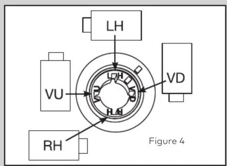
SPLINE KEY POSITION CHART
The lock may be mounted in four positions - align the spindle groove with the corresponding cam position. The positions are marked as follows:
RH (RIGHT HAND)
Lock bolt points right as you face the back of the door.
LH (LEFT HAND)
Lock bolt points left as you face the back to the door.
VU (VERTICAL UP)
Lock bolt points upward.
VD (VERTICAL DOWN)
Lock bolt points downward.
- If other parts of the boltwork are to be connected to the lock unit (e.g., for activating a blocking device), corresponding adapters can be fixed with screws (#10-32 or M4) to the front of the lock bolt (tightening torque for 15mm screwing depth: 200Ncm maximum).
Group 2M Mechanical Lock (3390 Series) INSTALLATION INSTRUCTIONS
- If required, locate, drill and tap the two holes to mount dial ring, the spindle hole, and three holes to mount the lock assembly to the inside of the safe door. Use the installation template (P/N 740.118) available on-line at www.kaba-mas.com.
- Attach the lock assembly to the door using the three US mounting screws provided. Tighten the mounting screws to a torque setting of 30 in./lbs. (3.4 N°m). Insert short mounting screws into the hole with marking (Figure 6). This screw is not removed during servicing of the lock.
NOTE: Ensure the lock assembly spindle hole is properly aligned with the spindle through hole in the safe door.
- Measure total mounting thickness (door thickness + mounting plate) (Figure 2).
- Cut the spindle to a length of .875" (23 mm) plus the total mounting thickness.
- Mount the dial ring centered on the through hole, and attach to the safe door using the two mounting screws supplied with the dial assembly. The opening index reference mark must be in the twelve o'clock position (Figure 3).
NOTE: It is recommended that the lock bolt remain in the retracted position throughout the installation procedure, to prevent interference by the boltworks during installation. To ensure this keep one finger over the bolt while mounting the lock and installing the spindle. If the bolt extends at any point during the installation procedure; the bolt may be retracted by following the instructions in the section on Retracting the Lock Bolt.

Figure 7 Figure 8
- Insert the spindle through the spindle hole of the door. With the bolt retracted, carefully thread (clockwise) the spindle into the drive cam until tight. Next, rotate (counterclockwise) at least 1/2 turn until the groove in the spindle is aligned with the correct spline position. (Refer to the Spline Key Position Chart - Figure 4).
- Insert the spline key fully by tapping into place with a screwdriver using insertion notch (Figure 5).
- Install Cover Insert (P/N 705002), Figure 8. Press the insert into the cover using even pressure. The insert is designed to prevent spline key movement. Once installed do not attempt to remove the insert. Remove the back cover to service the lock; this will not void the factory warranty.
LA GARD mechanical locks are shipped with the factory combination of 50.
To open the lock:
- Turn dial to the LEFT (counter-clockwise) passing 50 at least four times.
- Stop when 50 lines-up with the Opening Index (Figure 3).
- Turn RIGHT (clockwise) until dial stops. This will retract the bolt. (This may vary slightly by one or two numbers either up or down due to variations in alignment of dial ring during installation.)
NOTE: If using the VisionGard Dial (2085 or 2090 Series) and a lock with the factory combination, then the lock will open on 47.
Security Recommendation: Security relevant parts of a high security lock should not be accessible to unauthorized persons when the door of the secure storage unit to which it is fitted is open.
RETRACTING THE LOCK BOLT
The 3390 Series Group 2M Mechanical lock is shipped with the bolt in the retracted position. If the bolt becomes extended during the installation process, it can be retracted before splining the lock.
To retract the bolt:
- While viewing the back of the lock, insert a small flat object, such as a screwdriver, into the spline notches in the cam in order to rotate.
- Rotate the cam to the right (clockwise) at least 4 complete revolutions.
- Then align the mark on the drive cam with the one on the back cover (Figure 7). (Mechanical tolerance +/- the width of the of the case alignment mark.)
- Rotate the cam to the left (counterclockwise) until the bolt is retracted (approximately 1/2 turn).
- Holding the bolt in the retracted position, the spindle can now be threaded into the cam without the cam rotating. Insert the spline key using the spline key position chart.
- INSTALLATION INSTRUCTIONS
- SAFEGUARDS FOR MOUNTING
- Group 2M Mechanical Lock (3390 Series)
- DESIGN PARAMETERS FOR MECHANICAL COMBINATION LOCKS
- Prepare for New Installation of the Lock (If Required)
- SPLINE KEY POSITION CHART
- RH (RIGHT HAND)
- LH (LEFT HAND)
- VU (VERTICAL UP)
- VD (VERTICAL DOWN)
- Group 2M Mechanical Lock (3390 Series) INSTALLATION INSTRUCTIONS
- LA GARD mechanical locks are shipped with the factory combination of 50.
- To open the lock:
- RETRACTING THE LOCK BOLT
- To retract the bolt:
Brand : Dormakaba
Model : La Gard 3390
Category : Serrure mécanique