
XY I/O 1U - Keyboard Intellijel - Free user manual and instructions
Find the device manual for free XY I/O 1U Intellijel in PDF.


| Product Type | Eurorack 1U Passive Utility Module |
| Brand | Intellijel |
| Model | XY I/O 1U |
| Width | 4 HP (20 mm) |
| Height | 1U (44.45 mm) |
| Maximum Depth | 24 mm |
| Weight | Approx. 50 g |
| Power Requirement | None (passive module) |
| Current Draw | 0 mA |
| Front Panel Connectors | 2x 3.5mm TRS jacks (X and Y) |
| Rear Panel Connectors | 3x 3-pin LINK headers (JP1, JP2, JP3) |
| Compatibility | Intellijel Mixup, Pedal I/O, Switched Mult 1U, and other LINK-equipped modules |
| Main Function | Provides send/return, additional stereo I/O, or bus expansion via X and Y jacks |
| Regulatory Compliance | FCC Part 15, CE (EMC, LVD, RoHS, WEEE) |
| Installation | Fits Intellijel 1U rows (4U, 7U cases) |
| Maintenance | None required; keep dry and dust-free |
| Safety | Complies with FCC and CE standards; no user-serviceable parts |
| Spare Parts | Not applicable; non-repairable unit |
| Manufacturer | Intellijel Designs |
Frequently Asked Questions - XY I/O 1U Intellijel
User questions about XY I/O 1U Intellijel
0 question about this device. Answer the ones you know or ask your own.
Ask a new question about this device
Download the instructions for your Keyboard in PDF format for free! Find your manual XY I/O 1U - Intellijel and take your electronic device back in hand. On this page are published all the documents necessary for the use of your device. XY I/O 1U by Intellijel.
USER MANUAL XY I/O 1U Intellijel
Link Connector Access Jacks
TABLE OF CONTENTS
COMPLIANCE 2
INSTALLATION 3
OVERVIEW 4
FRONT & BACK PANELS 4
OTHER USES 6
TECHNICAL SPECIFICATIONS 6
COMPLIANCE

This device complies with Part 15 of the FCC Rules. Operation is the following two conditions: (1) this device may not cause harmful interference, and (2) this device must accept any interference received including interference that may cause undesired operation.
Changes or modifications not expressly approved by Intellij Designs, could void the user's authority to operate the equipment.
Any digital equipment has been tested and found to comply with the a Class A digital device, pursuant to part 15 of the FCC Rules. The are designed to provide reasonable protection against harmful interfere when the equipment is operated in a commercial environment. This generates, uses, and can radiate radio frequency energy and, if not and used in accordance with the instruction manual, may cause harm interference to radio communications.

This device meets the requirements of the following standards and d
EMC: 2014/30/EU
EN55032:2015 ; EN55103-2:2009 (EN55024) ; EN61000-3-2 ; EN61000
Low Voltage: 2014/35/EU
EN 60065:2002+A1:2006+A11:2008+A2:2010+A12:2011
RoHS2: 2011/65/EU
WEEE: 2012/19/EU
INSTALLATION
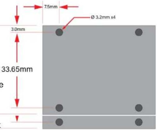
This module is designed for use within an Intellijel-standard 1U row, such as contained within the Intellijel 4U and 7U Eurorack cases. Intellijel's 1U specification is derived from the Eurorack mechanical specification set by Doepfer that is designed to support the use of lipped rails within industry standard rack heights.
Because XY IO 1U is a passive module, it requires no power to operate.

OVERVIEW
Use this module to tap into the 3-pin LINK connector used in several Intellijel products, including Mixup, Switched Mult 1U, Pedal I/O and the various Palette and 7U cases (NOTE: 7U cases requires a 2nd Generation Audio Jacks Board).
It uses two 3.5mm TRS jacks, which accept insert cables to provide send/return capability to a pair of Pedal I/O's, or additional stereo inputs (or outputs) to a pair of Mixups, or one of each.
A third 3-pin Link connector on the back panel allows the X and Y jacks to sum with the X and Y busses on a Switched Mult 1U, or to access the L/R (or Send/Return) jacks on a single connected module or case without needing a stereo cable.
FRONT & BACK PANELS
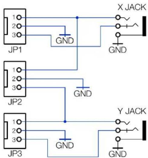
[X] X - This stereo 3.5mm (tip/ring/sleeve) jack connects to JP1 [1] and JP2 [2] on the back panel as follows:
TIP: connects to both JP1 PIN 1 and JP2 PIN 1
RING: connects to JP1 PIN 3
SLEEVE : Ground
[Y] Y - This stereo 3.5mm (tip/ring/sleeve) jack, connects to JP2 [2] and JP3 [3] on the back panel as follows:
TIP: connects to both JP3 PIN 1 and JP2 PIN 3
RING: connects to JP3 PIN 3
SLEEVE : Ground
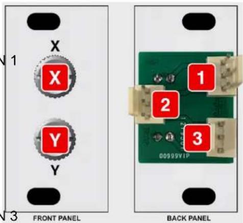
The illustration on the right shows how the X and Y jacks are wired to the JP1, JP2 and JP3 jacks on the back panel.
[1] JP1 - This 3-pin LINK connector is internally wired to the X [X]
TRS jack on the front panel as follows:
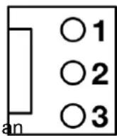
3-PIN LINK CONNECTOR
(JP1 - JP3)
PIN 1: connects to X TIP
PIN 2: connects to ground
PIN 3: connects to X RING
Connect this to another module's 3-pin Link Connector.
Example 1: Mixup - Connecting JP1 to the CHAIN IN on Intellijel Mixup gives you an extra stereo input through the front panel X jack, where X TIP = LEFT CH of Mixup, and X RING = RIGHT CH of Mixup.
Example 2: Pedal I/O - Connecting JP1 to a Pedal I/O provides you with send and return on
a single 3.5mm TRS insert cable, where X TIP = SEND and X RING = RETURN.
[2] JP2 - This 3-pin LINK connector is wired to both the X [X] and Y [Y] TRS jacks on the front panel. Specifically:
PIN 1: connects to X TIP
PIN 2: connects to ground
PIN 3: connects to Y TIP
This has numerous uses, including:
- Connecting a Switched Mult 1U, such that an extra jack is added to both the Switched Mult's X and Y busses.
- Connecting a Pedal I/O without using a TRS insert cable. Specifically:
X jack (TIP) = SEND to Pedal
Y jack (TIP)= RETURN from Pedal.
- Feeding the Left and Right CHAIN IN connector on a Mixup using regular mono eurorack cables. Specifically:
X jack (TIP) = LEFT input to Mixup
Y jack (TIP)= RIGHT input to Mixup.
[3] JP3 - This 3-pin LINK connector is internally wired to the Y [Y] TRS jack on the front panel as follows:
PIN 1: connects to Y TIP
PIN 2: connects to ground
PIN 3: connects to Y RING
This works as described for JP1, and provides the same connection options to external modules, except that the Y jack (and not the X) is connected to JP3.
OTHER USES
Other usages are possible given a bit of ingenuity. These include:
- Make a Midi TRS Type-A to Type-B converter by cross patching the pins on the back with a jumper cable
- Make an 18 " Floating Ring converter by linking the two together with only 2 of the pins
- Simple 14 " to 18 " converter with the Case Jacks
- Add an additional set of 1/8" inputs to Mixup (via Mixup's CHAIN IN) — handy for patching in small external synths (like Korg's Volca series), which have 1/8" outputs.
- Add additional jacks to the X and Y busses on a Switched Mult 1U.
- Use the Jacks as an (NOTE) header to link I2C modules across cases
- I2C (NOTE) from something like the ER-301 (3Pin) to the 16-N Faderbank (TRS)
NOTE: Mileage may vary with I2C, depending on the hardware involved.
TECHNICAL SPECIFICATIONS
| Width | 4 hp |
| Maximum Depth | 24 mm |
| Current Draw | No current draw - module is passive |
Brand : Intellijel
Model : XY I/O 1U
Category : Keyboard