
CMRC1-SB - VHF Radio CLARION - Free user manual and instructions
Find the device manual for free CMRC1-SB CLARION in PDF.


| Product Type | Marine Remote Control Panel |
| Model | CMRC1-SB (CMRC1-BSS/SB) |
| Brand | Clarion |
| Compatible Head Units | Clarion CMD4 or M455 AM/FM/CD Player |
| Max Number of Remotes | 2 (with optional M101RYC adapter) |
| Power Supply | 12V DC, negative ground |
| Mounting Hole Diameter | 2 inches (51 mm) |
| Required Mounting Depth | 2.5 inches (64 mm) |
| Waterproof | Yes (waterproof remote panel) |
| Illumination | Backlit, connects to boat illumination circuit (0.5A in-line fuse required) |
| Key Functions | Power/Source, Band/Disc, Mute/Play/Pause, Volume Up/Down, Select Up/Down |
| Wiring | Ground via ring terminal to boat negative; DIN cable to head unit |
| Included Accessories | Mounting bracket, four 7mm hex nuts, owner's manual |
| Optional Accessories | 24-inch extension DIN cable (M101RXC), M101RYC adapter for second remote |
| Warranty Duration | 1 year (2 years if installed by authorized Clarion dealer in USA/Canada) |
| Cleaning | Use soft damp cloth with household glass cleaner; avoid solvents |
| Safety Precautions | Disconnect negative battery before wiring; avoid pinching cables; use correct fuse amperage |
| Repairability | Warranty service by authorized Clarion service centers only; no user-serviceable parts inside |
| Certifications | Designed for marine use (boats with negative ground) |
Frequently Asked Questions - CMRC1-SB CLARION
User questions about CMRC1-SB CLARION
0 question about this device. Answer the ones you know or ask your own.
Ask a new question about this device
Download the instructions for your VHF Radio in PDF format for free! Find your manual CMRC1-SB - CLARION and take your electronic device back in hand. On this page are published all the documents necessary for the use of your device. CMRC1-SB by CLARION.
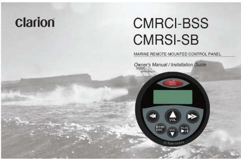
USER MANUAL CMRC1-SB CLARION
natural_image
Black-and-white photo of a large boat navigating choppy waters with splashing waves, no visible text or symbolsLIMITED WARRANTY INFORMATION For USA and Canada only
This product is warranted against all defects in material workmanship for a period of one year from the date of original purchase. Clarion ProAudio products, except for speakers, are covered by a two-year limited warranty when installed by an authorized Clarion dealer. The conditions of this limited warranty and the extent of responsibility of Clarion Corporation of America ("Clarion") under this limited warranty are as follows:
-
PROOF OF PURCHASE WILL BE REQUIRED FOR WARRANTY SERVICE OF THIS PRODUCT, IN THE CASE OF THE TWO (2) YEAR LIMITED WARRANTY FOR CLARION PROAUDIO PRODUCTS. PROOF OF INSTALLATION BY AN AUTHORIZED DEALER IS REQUIRED: INFORMATION ABOUT CLARION AUTHORIZED WARRANTY SERVICE CENTERS MAY BE OBTAINED BY CONTACTING CLARION AT THE ADDRESS BELOW.
-
This limited warranty will become void if service performed by anyone other than an approved Clarion Warranty Service Center results in damage to the product.
- This limited warranty does not apply to any product which has been subject to misuse, neglect or accident, or which has had the serial number altered, defaced or removed, or which has been connected, installed, adjusted or repaired, other than in accordance with the instructions furnished by Clarion.
- This limited warranty does not cover vehicle static or other electrical interferences, tape head or laser pick-up cleaning or adjustments, or labor posts for the removal or reinstallation of the unit for repair.
-
The sole responsibility of Claron under this limited warranty shall be limited to the repair of the product or replacement of the product, at the sole discretion of Claron.
-
Product must be shipped in its original carton or equivalent carton, fully insured, with shipping charges prepaid. Clarion will not assume any responsibility for any loss or damage incurred in shipping.
- ALL IMPLIED WARRANTIES EXCEPT TO THE EXTENT PROHIBITED BY APPLICABLE LAW SHALL HAVE NO GREATER DURATION THAN THE WARRANTY PERIOD SET FORTH ABOVE UNDER NO CIRCUMSTANCES SHALL CLARION BE LIABLE FOR ANY LOSS OR DAMAGE, DIRECT OR CONSEQUENTIAL, ARISING OUT OF THE USE OR INABILITY TO USE THE PRODUCT. BECAUSE SOME STATES DO NOT ALLOW LIMITATIONS ON HOW LONG AN IMPLIED WARRANTY LASTS OR EXCLUSIONS OR LIMITATIONS OF INCIDENTAL OR CONSEQUENTIAL DAMAGES, THE ABOVE LIMITATIONS OR EXCLUSIONS MAY NOT APPLY TO YOU.
- THIS LIMITED WARRANTY GIVES YOU SPECIFIC LEGAL RIGHTS, AND YOU MAY ALSO HAVE OTHER RIGHTS WHICH VARY FROM STATE TO STATE.
- Should you have any difficulties with the performance of this product during the warranty period, please call or visit our web site (www.clarion.com) for a listing of Authorized Warranty Service Centers in your area. You may also contact Clarion at the address listed below.
In USA:
Clarion Corporation of America
661 W. Redondo Beach Place
681 W. Redondo Beach SWC Gardena, CA 90247-4201
1-800-GO-CLARION
(310) 327-9100
www.clarion.com
n Canada
Clarion Canada, Inc.
Warranty Service Center
2258 Winston Park Drive Oakville, Ontario 6H 18
(905) 829-4600
www.clarioncanada.com
CMRCI-BSS/SB
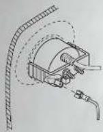
- Connecting the illumination lead.
The illumination circuit of the CMRCI-BSS/SB operates with a +12V input. Wire with a .250 female insulated spade terminal (not supplied), and connect the illumination terminal on the rear of the panel to a 0.5A in-line fuse (not supplied). Connect the other side of the fuse to an illumination circuit boat.
- Connecting the cables.
Connect the DIN cable from the CMD4 or M455 AM/FM/CD
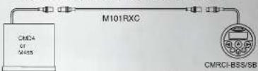
Connecting one remote to the CMD4 or M455
with optional M101RXC DIN cable.
M101RYC
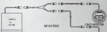
Connecting two remotes to the CMD4 or M455 using an
optional M101RYC and two M101RXC DIN cables.
CMRCI-BSS/SE
NOTE: A maximum of two remotes can be connected
to the CMD4 or M455.
Precautions
Make certain that the remote is installed in a location which does not interfere with the safe and proper operation of the boat
The CMRCI-BSS/SB is only compatible with the CMD4 or
M455 / XMD3 AM/FM/CD Player
About Installation
Installation of Clarion Marine audio components requires experience with a variety of mechanical and electrical procedures. Even though this Manual provides general installation and operation instructions for your new Clarion Marine audio remote control panel, it does not show the exact methods which may be required for your particular installation.
If you do not have the required knowledge and experience to successfully complete the installation, we strongly recommend consulting an authorized Clarion Marine audio dealer about professional installation options.
Table of Contents
Page
-
Introduction.
-
Care and Maintenance.
-
Using the Remote Control Panel.
-
Installation and Wiring
-
Limited Warranty Information....11
1. INTRODUCTION
The CMRCI-BSS/SB is a waterproof remote control panel which allows operation of the Clarion CMD4 or M455 head unit from a remote location. The CMD4 or M455 unit is an AM/FM CD player with controls for an optional CD changer and an optional Sinus Satellite Radio receiver.
A maximum of two remotes units may be used with a single CMD4 or M456 (using an optional M101RYC adapter) The CMRCI-BSS/SB can be connected to your boat's illumination circuit, backlighting the panel in low-light conditions.
2. CLEAN AND MANTAINANCE
Clean the remote control panel with a slightly damp, soft cloth using household glass cleaner. Do not use solvents such as benzene, thinner, or commercially available cleaners.
From time to time, inspect the connections on the rear of the unit for corrosion and correct as needed.
What is included
- Remote control panel (1)
• One mounting bracket and four 7mm hex nuts (1 set)
• Owner's Manual / Installation Guide (1)
Note: An 24" extension DIN cable is available separately (P/N M101RXC).
4 CMRCI-BSS/SB
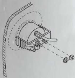
- Position the bracket onto the rear of the remote control panel, sliding the two threaded studs on the rear of the panel through the two holes in the mounting bracket (as shown below). Tighten the 7mm hex nuts into bracket again insuring that the gasket seals seals tightly to the front of mounting surface. Avoid pinching the cable.
natural_image
Diagram of a mechanical device with a curved pipe and two circular components emitting light (no text or symbols)Wiring Connections
Take the following precautions before wiring your system.
- Disconnect the negative battery terminal before making any wiring connections.
- Be particularly careful where you route wires and cables. Keep them away from the engine, exhaust system, etc. Heat may damage wires. Sharp edges can pierce wire insulation and cable jackets, causing short circuits, damage to the craft, blown fuses, and system failure.
- If any fuse should blow, make sure all connections are correct and no wires are damaged before replacing the fuse. Always use fuses that are the same amperage value as the
Wiring
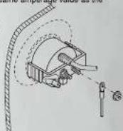
- Connecting the ground lead.
Connect a wire to one of the mounting studs on the rear of the unit, using a ring terminal (not supplied). Connect this wire to the boat's negative (-) ground.
CMRCI-BSS/SB 9
- Determine the mounting location is a flat surface with sufficient rear clearance (2.5") and access. Ensure that the installation can be successfully completed before continuing! If the cable is not long enough, a 24' extension is available - P/N M101RXC.
- The remote control panel requires a 2" (51mm) diameter round hole. Cut the hole and insert the remote control panel as shown.

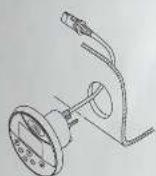
- The mounting bracket is scored with "break lines" to allow use with panels of different thicknesses. Determine if the bracket needs to be shortened, and remove the appropriate number of breakaway segments using a pair of pliers. Each segment is 1/4" long.
B CMPCI-BSS/SB
Mounting Bracket
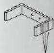
Break Lines
- Insert the remote control panel into the opening. Make sure that the gasket behind the remote control panel face seats completely against the mounting surface.
- Position the bracket onto the rear of the remote control panel, sliding the two threaded studs on the rear of the panel through the two holes in the mounting bracket (as shown below). Tighten the 7mm hex nuts onto the bracket, again ensuring that the gasket seals tightly to the front of the mounting surface. Avoid pinching the cable.
USING THE REMOTE CONTROL PANEL
Using the Remote Control Panel
The CMRCI BSS/SB remote control allows the user to control the Clarion CMD4 or M455. AM/FM/CD Player from a remote location, even if the source unit is mounted out of sight in a compartment or in a different area.
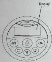
The [POWER/SOURCE] button:
POWER
SOURCE
To turn the unit on, press this button momentarily. To turn the unit off, press and hold for 1 second.
When the CMD4 is already on, press momentarily to switch between the CD and the AM/FM tuner. This button also accesses the optional Sirius Satellite Radio receiver and the optional CD Changer
The [BAND/DISC] button:
![CLARION CMRC1-SB - The [POWER/SOURCE] button: - 1](/content/2026/05/826054/images/512bba58d9997f49768e8446fcc8a16e62f102384303d9c01ed94fed275db4f7.jpg)
In Radio and Sirius Satellite Radio modes: Switches among AM, FM, and optional Sirius Satellite Radio bands, and selects among the various memory registers (FM1, FM2, SR1, SR2, etc.) In CD Changer mode: selects the next available CD. In CD mode: begins playback from the beginning of the CD.
CMRCI-BSS/SB 5
The [MUTE/PLAY/PAUSE] button
![CLARION CMRC1-SB - The [POWER/SOURCE] button: - 2](/content/2026/05/826054/images/51ab0191b282941c93c8c70c1fdc824331fbf1cadb54ded8fdf6d377b47cf0b6.jpg)
In the Radio mode: this button mutes the system. press the button again to defeat the mute feature.
In the CD mode, this bottom pauses playback of the CD To resume playback, press this button again
The [VOLUME UP/DOWN] buttons
![CLARION CMRC1-SB - The [POWER/SOURCE] button: - 3](/content/2026/05/826054/images/62317e71b97492d24f7644322ac2806219cd14be28bdae8c03fc6b69061caa6e.jpg)
These increase and decrease the system volume. If the function is active, pressing one of these buttons defeats the mute function.
The [SELECT UP/DOWN] buttons
![CLARION CMRC1-SB - The [POWER/SOURCE] button: - 4](/content/2026/05/826054/images/75b131bcce731efd4ebb4a2f5dab570927233722d713bbebd84999918850798c.jpg)
![CLARION CMRC1-SB - The [POWER/SOURCE] button: - 5](/content/2026/05/826054/images/73a551994d88aaba60dc8d47fd51add0319229f1906ca6e7d72374a64dc97e38.jpg)
In Radio mode: these buttons select the next preset radio station in the memory.
In CD modes (single-disc and CD changer), these buttons serve two functions:
Track navigation: To select the next track on the disc, press and release the ➤ button.
To return to the beginning of the current track, press and release the < button.
To "back up" a few tracks, press and release the button repeatedly until the desired track number is displayed. Searching within a track: To fast-forward or fast-reverse within the track, press and hold the > or < button
In optional Sirius Satellite Radio mode: These buttons select the next preset radio station in the memory.
4. INSTALLATION AND WIREING
1. Before Starting
Read these instructions and the following precautions.
Precautions
- This unit is exclusively for boats with a negative ground and 12V power supply.
- Do not open the case. There are no user-serviceable parts inside. If you require assistance, consult your Marine Audio dealer or an authorized Clarion service center.
- Use a soft, dry cloth to gently clean the control panel after installation. Never use a rough cloth, thinner, benzene, alcohol, or other solvent. The screen surface can be scratched - do not rub when cleaning.
2. Package Contents
■ Remote Control Panel unit (1)
■ One mounting bracket and four 7mm hex nuts (1 set)
■ Owner's Manual / Installation Guide (1)
3. Installing the Unit
Selecting the Location
Before you begin installation of the remote control panel, verify that you have sufficient clearance in the desired location. Note that 2.5 inches of mounting depth (behind the mounting surface) is required to avoid cable damage. A flat surface is required in order to ensure a watertight seal when installation is complete.
WARNING!
Before cutting any panel, ALWAYS ensure that there is sufficient clearance behind the panel, and that no wire harnesses, fuel lines, moving linkages, or any other critical components are exposed to damage by your choice of location. NEVER risk damage to the hull while cutting you opening.
Prepare the boat for installation by carefully removing interior trim panels as necessary. Route wire harnesses away from sharp edges, and ensure that no harnesses will be pinched or pierced during reassembly.
6 CMRCI-BSS/SB
CMRCI-BSS/SB 7
- LIMITED WARRANTY INFORMATION For USA and Canada only
- Precautions
- About Installation
- Table of Contents
- INTRODUCTION
- CLEAN AND MANTAINANCE
- What is included
- Wiring Connections
- Wiring
- USING THE REMOTE CONTROL PANEL
- The [POWER/SOURCE] button:
- INSTALLATION AND WIREING
- Before Starting
- Package Contents
- Installing the Unit
- Selecting the Location
- WARNING!
Brand : CLARION
Model : CMRC1-SB
Category : VHF Radio