
925 - Anemometer FLUKE - Free user manual and instructions
Find the device manual for free 925 FLUKE in PDF.


| Product Type | Anemometer (Air Velocity, Air Flow, Temperature) |
| Brand | Fluke |
| Model | 925 |
| Display | Dual 4-digit (9999 count) LCD |
| Measurement Units | Air Velocity: ft/min, m/s; Air Flow: cfm, cms; Temperature: °F, °C |
| Air Velocity Range | 0.40 to 25.00 m/s or 80 to 4900 ft/min |
| Air Velocity Accuracy | ±2% of full scale |
| Air Flow Range | 0.01 to 99.99 cms (m³/sec); 1 to 9999 cfm (ft³/min) |
| Temperature Range | 32 °F to 122 °F (0 °C to 50 °C) |
| Temperature Accuracy | ±1.5 °F (0.8 °C) |
| Sensor Type (Velocity) | Conventional angled vane arms with low-friction ball bearing |
| Sensor Type (Temperature) | Precision thermistor |
| Data Hold | Yes, freezes displayed reading |
| MIN/MAX/AVG Recording | Single point (up to 2 hours) or Multi-point (up to 8 readings) |
| Auto Power Off | After 20 minutes (disposable with button combination) |
| Power Supply | 9 V battery (Heavy duty alkaline, IEC 6LR61) |
| Battery Life | Approximately 100 hours |
| Dimensions (Main Instrument) | 7.1 x 2.8 x 1.4 in (181 x 71 x 38 mm) |
| Sensor Head Diameter | 70 mm |
| Weight (including battery and sensor) | 0.8 lb (363 g) |
| Operating Temperature | 32 °F to 122 °F (0 °C to 50 °C) |
| Operating Humidity | Max 80% RH |
| Warranty | 1 year limited warranty |
| Accessories Included | Sensor, 9V battery, user manual |
Frequently Asked Questions - 925 FLUKE
User questions about 925 FLUKE
0 question about this device. Answer the ones you know or ask your own.
Ask a new question about this device
Download the instructions for your Anemometer in PDF format for free! Find your manual 925 - FLUKE and take your electronic device back in hand. On this page are published all the documents necessary for the use of your device. 925 by FLUKE.
USER MANUAL 925 FLUKE
January 2009, Rev.1, 5/18
© 2009-2018 Fluke Corporation, All rights reserved. Specifications are subject to change without notice. All product names are trademarks of their respective companies.
LIMITED WARRANTY AND LIMITATION OF LIABILITY
Each Fluke product is warranted to be free from defects in material and workmanship under normal use and service. The warranty period is one year and begins on the date of shipment. Parts, product repairs, and services are warranted for 90 days. This warranty extends only to the original buyer or end-user customer of a Fluke authorized reseller, and does not apply to fuses, disposable batteries, or to any product which, in Fluke's opinion, has been misused, altered, neglected, contaminated, or damaged by accident or abnormal conditions of operation or handling. Fluke warrants that software will operate substantially in accordance with its functional specifications for 90 days and that it has been properly recorded on non-defective media. Fluke does not warrant that software will be error free or operate without interruption.
Fluke authorized resellers shall extend this warranty on new and unused products to end-user customers only but have no authority to extend a greater or different warranty on behalf of Fluke. Warranty support is available only if product is purchased through a Fluke authorized sales outlet or Buyer has paid the applicable international price. Fluke reserves the right to invoice Buyer for importation costs of repair/ replacement parts when product purchased in one country is submitted for repair in another country.
Fluke's warranty obligation is limited, at Fluke's option, to refund of the purchase price, free of charge repair, or replacement of a defective product which is returned to a Fluke authorized service center within the warranty period.
To obtain warranty service, contact your nearest Fluke authorized service center to obtain return authorization information, then send the product to that service center, with a description of the difficulty, postage and insurance prepaid (FOB Destination). Fluke assumes no risk for damage in transit. Following warranty repair, the product will be returned to Buyer, transportation prepaid (FOB Destination). If Fluke determines that failure was caused by neglect, misuse, contamination, alteration, accident, or abnormal condition of operation or handling, including overvoltage failures caused by use outside the product's specified rating, or normal wear and tear of mechanical components, Fluke will provide an estimate of repair costs and obtain authorization before commencing the work. Following repair, the product will be returned to the Buyer transportation prepaid and the Buyer will be billed for the repair and return transportation charges (FOB Shipping Point).
THIS WARRANTY IS BUYER'S SOLE AND EXCLUSIVE REMEDY AND IS IN LIEU OF ALL OTHER WARRANTIES, EXPRESS OR IMPLIED, INCLUDING BUT NOT LIMITED TO ANY IMPLIED WARRANTY OF MERCHANTABILITY OR FITNESS FOR A PARTICULAR PURPOSE. FLUKE SHALL NOT BE LIABLE FOR ANY SPECIAL, INDIRECT, INCIDENTAL, OR CONSEQUENTIAL DAMAGES OR LOSSES, INCLUDING LOSS OF DATA, ARISING FROM ANY CAUSE OR THEORY.
Since some countries or states do not allow limitation of the term of an implied warranty, or exclusion or limitation of incidental or consequential damages, the limitations and exclusions of this warranty may not apply to every buyer. If any provision of this Warranty is held invalid or unenforceable by a court or other decision-maker of competent jurisdiction, such holding will not affect the validity or enforceability of any other provision.
Fluke Corporation
P.O. Box 9090
Everett, WA 98206-
9090
U.S.A.
Fluke Europe B.V.
P.O. Box 1186
5602 BD Eindhoven
The Netherlands
11/99
To register your product online, visit http://register.fluke.com
flowchart
graph TD
    A["2"] --> B["FUNC"]
    B --> C["SELECT HOLD"]
    C --> D["UNIT SETUP"]
    D --> E["AVG"]
    E --> F["MULTI POINT"]
    G["1"] --> H["SINGLE POINT"]
    I["4"] --> J["SINGLE POINT"]
    K["3"] --> L["VELOCITY FLOW (area)"]
    M["5"] --> N["VELOCITY FLOW (area)"]
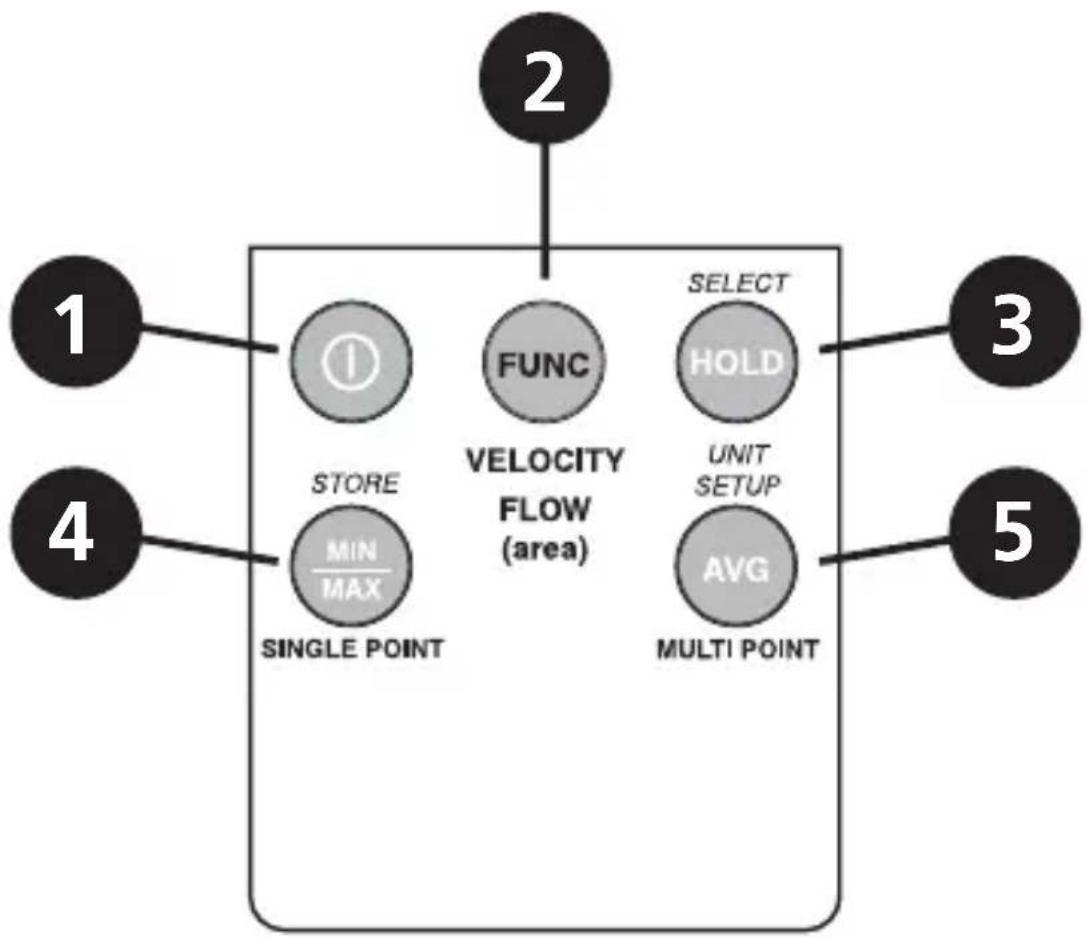
1 ON/OFF — Turns the meter on and off.
2 FUNC — Toggle between velocity, free area, and volume.
3 HOLD — Captures a reading. Sets digit to the desired value.
4 MIN MAX — View the minimum or maximum. Average or record value.
5 AVG — Display the average of all the measurements. Select the next digit for editing.
CONTENTS
Symbols....5
Auto Power Off 5
Error Message Display ....5
Display Indicators 6
Making Measurements....7
Air Velocity Measurements....7
Air Flow Measurements ....7
Single Point MIN/MAX/AVG Recording....8
Multi Point Average Recording....9
Data Hold Feature....9
Changing the Units of Measure....10
Useful Equations and Conversions ....10
Cubic Equations....10
Units Conversion Table....10
Replacing the Battery 11
Specifications 11
SYMBOLS
The following symbols are used on the Product and in this manual.
| Symbol Description | |
 | WARNING.RISK OF DANGER. |
 | Consult user documentation. |
 | Battery or battery compartment. |
 | Conforms to relevant South Korean EMC Standards. |
 | Conforms to relevant Australian Safety and EMC standards. |
| CE | Conforms to European Union directives. |
 | This product complies with the WEEE Directive marking requirements. The affixed label indicates that you must not discard this electrical/electronic product in domestic household waste. Product Category: With reference to the equipment types in the WEEE Directive Annex I, this product is classed as category 9 “Monitoring and Control Instrumentation” product. Do not dispose of this product as unsorted municipal waste. |
AUTO POWER OFF
The Fluke-925 Anemometer turns off automatically after 20 minutes to conserve battery power. Press the Ⓐ and HOLD buttons to disable the Auto Power Off feature.
ERROR MESSAGE DISPLAY
If the sensor is not connected to the meter or if the sensor is inoperable, the meter beeps, the error message "E6" appears on the display, and the meter shuts down. Connect the sensor or return the meter and sensor for repair.
DISPLAY INDICATORS
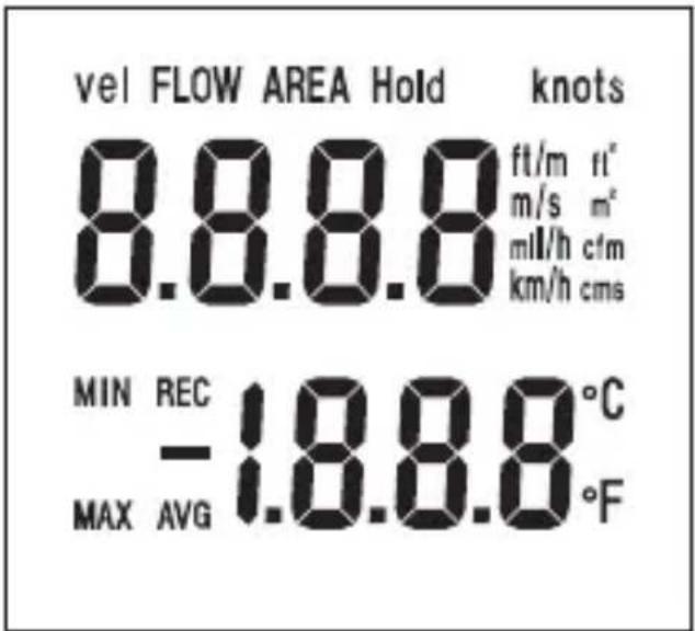
Vel Air velocity measurement.
FLOW Air flow/air volumen.
AREA Free area default setting.
Hold Freezes the reading.
knots 1850 meters per hour (not available).
ft/m Feet per minute.
ft ^2 Square feet.
m^2 Square meters.
mil/h Miles per hour (not available).
cfm Cubic feet per minute.
km/h Kilometers per hour (not available).
cms Cubic meters per second.
Primary display Numerical display for air velocity, air volume, and free area digit.
°C Celsius units.
°F Fahrenheit units.
Secondary display Temperature display or record number.
MIN Minimum data.
MAX Maximum data.
REC Record and saved.
AVG Average data.
- Polarity indicator for negative temperature.
MAKING MEASUREMENTS
Air Velocity Measurements
Air velocity and temperature measurements can be displayed on this meter in the following units of measure: ft/m (feet per minute) or m/s (meters per second) for air velocity and °F or °C for temperature.
- Connect the sensor to the sensor input jack on top of the meter.
- Turn on the meter using the Ⓐ button.
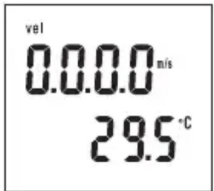
- The 'Vel' indicator should appear on the upper left on the LCD. If not, press and hold the MODE button until a beep is heard. Repeat this procedure until 'Vel' appears on the display.
- Place the sensor in the air current to be measured.
- View the air velocity and temperature readings on the LCD Display. The upper display shows the air velocity reading. The lower display shows the temperature.
Air Flow Measurements
In order to take air flow measurements, the area of the duct under test (in ft ^2 or m ^2 ) must first be determined (check with the duct manufacturer if necessary). Once the area is known, enter the value as follows:
- Turn on the meter with the Ⓐ button.
- Press and hold the FUNC button until a beep is heard. "AREA" appears on the display and one digit will be blinking indicating that value can be changed.
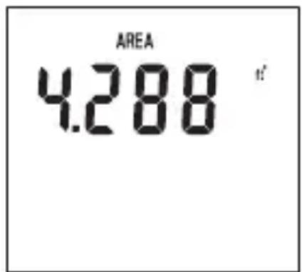
- Press the HOLD button to adjust the digit to the value needed.
- Press the AVG button to select the next digit for editing.
- When the area is correctly entered, press the MIN MAX button once. A beep will sound and the digits will stop blinking.
- Press the HOLD button once to store the area value.
- The meter is now ready to measure air flow. Place the sensor in the air current and view the air flow and temperature readings on the LCD.
Single Point MIN/MAX/AVG Recording
This meter can record and display the lowest (MIN), highest (MAX), and average (AVG) air velocity, air flow, and temperature readings.
- Follow the instructions for starting air velocity or air flow measurements detailed on the previous page.
- Press the MIN MAX button. The REC and AVG (average) indicators will appear on the display and the meter will begin recording data.
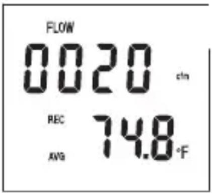
- When the measurement session is complete (up to 2 hours maximum), press the HOLD button until the beep sounds.
- To view the MIN reading, press the MIN MAX button twice or until the MIN indicator appears. The minimum reading will be displayed on the LCD.
- Press MIN MAX again to view the maximum value, the MAX indicator along with the maximum reading will appear on the LCD display.
- Press MIN MAX again to view the averaged value, the AVG indicator along with the average reading will appear on the LCD display.
- To exit this mode, press and hold the MIN MAX button until 2 beeps are heard in rapid succession and the display indicators (REC, MIN, MAX, AVG) disappear.
Multi Point Average Recording
The meter can take up to 8 separate measurements and average them automatically.
- Follow the instructions for starting air velocity detailed on the previous page.
- When the first measurement is taken and is on the display, press and hold the HOLD button. Release the button when the tone is heard.
- The reading will hold and the 'HOLD' icon will appear above it on the LCD.
- Press and hold the MIN MAX button until a tone is heard then release it. The LCD will briefly indicate a number (1 through 8) representing the current measurement number.
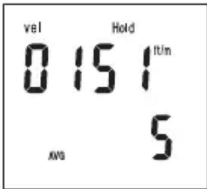
- Repeat this process until up to 8 measurements have been taken.
- Press the AVG button to display the average of all the measurements.
- To display the average air flow, press the FUNC button to enter the area, then FUNC again for air flow.
- To exit this mode and erase all stored readings, press and hold the AVG button until 2 beeps are heard. To exit without erasing readings, press the HOLD button.
Data Hold Feature
- While taking measurements you can freeze the displayed reading by pressing and holding the HOLD button until a beep is heard.
- The 'HOLD' indicator will appear on the LCD when the display is in this mode.
- Press and hold the HOLD button until a beep is heard to exit this mode.
Changing the Units of Measure
U.S. units of measure are °F, ft/m (feet per minute), and cfm (cubic feet per minute). Metric units are: °C, m/s (meters per second), and cms (cubic meters per second).
- Turn the meter on by pressing and holding both the ① and the AVG buttons simultaneously. Release the ① button first then release the AVG button. The units of measure will appear on the LCD.
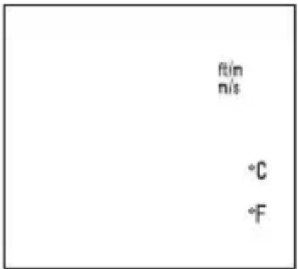
- Press the HOLD button to select Metric and the AVG button to select U.S.
- Press the MIN MAX button and an "S" will appear on the LCD.
- Press the HOLD button to advance to the next selection.
- The baud rate for PC Interface models will appear (1200 or 2400). Select the baud rate, if necessary, by pressing the HOLD (1200) or AVG (2400) button.
- To return to normal operation, press MIN MAX again (the "S" will reappear) then press and hold the HOLD button until the beep is heard.
USEFUL EQUATIONS AND CONVERSIONS
Cubic Equations
$$ \mathrm{cfm} (\mathrm{ft} ^ {3} / \min) = \text { Air Velocity } (\mathrm{ft} / \min) \times \text { Area } (\mathrm{ft} ^ {2}) $$
$$ \mathrm{cms} (\mathrm{m} ^ {3} / \sec) = \text { Air Velocity } (\mathrm{m} / \sec) \times \text { Area } (\mathrm{m} ^ {2}) $$
Units Conversion Table
| m/s ft/min | knots km/h | MPH | |||
| 1 m/s 1 196.87 1.944 3 | 6 2.24 | ||||
| 1 ft/min 0.00508 1 0.00 | 987 0.01829 | 0.01138 | |||
| 1 knot 0.5144 101.27 1 | 1.8519 1.1523 | ||||
| 1 km/h 0.2778 54.69 0.54 1 0.6222 | |||||
| 1 MPH 0.4464 87.89 0.8679 1.6071 | 1 |
REPLACING THE BATTERY
Replace the 9 V battery when the display is flashing or there is no display.
- Remove the Phillips head screw on the battery compartment cover.
- Lift off the rear battery compartment cover.
- Replace the 9 V battery and secure the battery compartment cover.
SPECIFICATIONS
Display Dual 4-digit (9999 count) LCD
Measurement units Air Velocity: ft/min (feet per minute); m/s
(meters per second)
Air Flow: cms (m³/sec) and cfm (ft³/min);
Temp: °C and °F
Data hold Freezes displayed reading
Sensors Air velocity/flow sensor: Conventional
angled vane arms with low-friction ball bearing.
Temp. sensor: Precision thermistor
MIN MAX Memory Record and view minimum and maximum readings
Average reading memory Single Point (up to 2 hours) or Multi-Point (up to 8 readings)
Automatic Power off Sleep mode (with bypass) after 20 mins. conserves energy
Operating Temperature 32 °F to 122 °F (0 °C to 50 °C)
Operating Humidity Max. 80 % RH
Power Supply 9 V battery (Heavy duty alkaline)
IEC 6LR61; Battery life: 100 hours
Weight 0.8 lb (363 g) including battery and sensor
Dimensions Main instrument: 7.1 x 2.8 x 1.4 in (181 x 71
x 38 mm)
Sensor head diameter: 70 mm
Electromagnetic compatibility (EMC)
International IEC 61326-1:Portable; CISPR 11:Group 1, Class A.
Group1: Equipment has intentionally generated and/or uses conductively-coupled radio frequency energy that is necessary for the internal function of the equipment itself.
Class A: Equipment is suitable for use in all establishments other than domestic and those directly.
Korea (KCC) Class A Equipment (Industrial Broadcasting & Communication Equipment)
Class A: Equipment meets requirements for industrial electromagnetic wave equipment and the seller or user should take notice of it. This equipment is intended for use in business environments and not to be used in homes.
Air Velocity Measurements
| Range Resolution Accuracy | ||
| m/s (meters per sec) | 0.40 to 25.00 m/s 0.01 m/s ±2% of full scale | |
| ft/min (feet per minute) | 80 to 4900 ft/min 1 ft/min ±2% of full scale |
Air Flow Measurements
| Range Resolution Area | |||
| cms (cubic meters per sec.) | 0.01 to 99.99 m^3/sec | 0.01 to 9.999 m | 2 |
| cfm (cubic feet per minute) | 1 to 9999 ft ^3 /min | 1.0 to 9.999 ft | 2 |
Air Temperature
| Range Resolution Accuracy | ||
| 32 °F to 122 °F (0 °C to 50 °C) | 0.1 °F/°C | ±1.5 °F (0.8 °C) |
- LIMITED WARRANTY AND LIMITATION OF LIABILITY
- CONTENTS
- SYMBOLS
- AUTO POWER OFF
- ERROR MESSAGE DISPLAY
- DISPLAY INDICATORS
- MAKING MEASUREMENTS
- Air Velocity Measurements
- Air Flow Measurements
- Single Point MIN/MAX/AVG Recording
- Multi Point Average Recording
- Data Hold Feature
- Changing the Units of Measure
- USEFUL EQUATIONS AND CONVERSIONS
- Cubic Equations
- Units Conversion Table
- REPLACING THE BATTERY
- SPECIFICATIONS
Brand : FLUKE
Model : 925
Category : Anemometer