
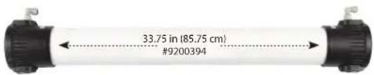
Spot Zero SZ 2000Z - Toilets DOMETIC - Free user manual and instructions
Find the device manual for free Spot Zero SZ 2000Z DOMETIC in PDF.

| Product Type | Reverse Osmosis Water Purification System |
| Brand | Dometic |
| Model | Spot Zero SZ 2000Z (SZ 2000) |
| Application | Marine fresh water from dock supply |
| Power Supply | 115V or 230V AC, single phase, 50/60Hz |
| Motor | 3/4 HP single phase |
| Pump | 5.3 GPM vane pump |
| Product Flow Rate | 1.38 GPM @ 77°F (25°C) |
| Recycle Flow Rate | 2 GPM |
| Concentrate Flow Rate | 1 GPM |
| Operating Pressure | 80-150 psi (max 175 psi) |
| Feed Water Minimum Pressure | 20 psi |
| Max Feed Water Temperature | 105°F (41°C) |
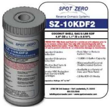
| Pre-Filtration | Sediment (1 micron) + GAC/KDF cartridge (part #252404005 and #252404004) |
| Membrane Type | Thin Film Composite Polyamide |
| Membrane Rejection | Typical >94% (e.g., 96.58% for TDS) |
| Controller | S-150 with TDS/Conductivity monitor, programmable setpoints |
| Timer | Auto flush timer (up to 12 hours) |
| Safety Features | Pressure fault shutdown, tank full shutdown, pretreat lockout |
| Maintenance | Replace pre-filters every 100 hours, membranes every 1000 hours |
| Included Accessories | Filter wrenches, hand-held TDS meter, sediment and carbon filters |
Frequently Asked Questions - Spot Zero SZ 2000Z DOMETIC
User questions about Spot Zero SZ 2000Z DOMETIC
0 question about this device. Answer the ones you know or ask your own.
Ask a new question about this device
Download the instructions for your Toilets in PDF format for free! Find your manual Spot Zero SZ 2000Z - DOMETIC and take your electronic device back in hand. On this page are published all the documents necessary for the use of your device. Spot Zero SZ 2000Z by DOMETIC.
USER MANUAL Spot Zero SZ 2000Z DOMETIC
INSTALLATION AND OPERATION MANUAL
SZ 2000 - SZ 3000
Dometic
SPOTZERO
TABLE OF CONTENTS
SZ 2000 - SZ 3000
INTRODUCTION 5
SYSTEM REQUIREMENTS & OPERATIONS GUIDELINES 5
PLUMBING 5
ELECTRICAL 5
PRE-FILTRATION 5
INSTALLATION 5
INSTALL TIPS 5
SPOT ZERO WIRING 7
STARTUP 8
PRODUCT FLOW METER & CONCENTRATE FLOW METER....8
RECYCLE VALVE 8
STARTUP 8
MEMBRANE TEMPERATURE CORRECTION FACTOR....9
MEMBRANE PERFORMANCE INSTRUCTIONS....10
MEMBRANE CHEMICAL CLEANING PROCEDURE 10
MEMBRANE REMOVAL & REPLACEMENT 10
MEMBRANE IDENTIFICATION 11
WEEKLY MAINTENANCE 11
DISPLAYING OR CHANGING SETPOINTS 23
SYSTEM OPERATION 23
DISPLAY ADJUSTMENT 24
TROUBLESHOOTING 24
INLET VALVE WILL NOT OPERATE 24
PUMPS, ACCESSORIES, REPLACEMENT PARTS 26
Your Spot Zero™ reverse osmosis system is a durable piece of equipment which, with proper care, will last for many years. This User's Manual outlines installation, operation, maintenance and troubleshooting details vital to the sustained performance of your system. Your system is designed to operate at a pressure of 80-150 psi, unless otherwise stated. The recovery set for your system is between 50%-75%.
NOTE: Prior to operating or servicing the Spot Zero™ reverse osmosis system, this User's Manual must be read and fully understood. Keep it and other associated information for future reference and for new operators or qualified personnel near the system.
CAUTION: Do not supply dock water to unattended vessel.
The membranes and high pressure pumps used on Spot Zero™ systems require a continuous and non-turbulent flow of water to the system with a minimum feed pressure of 20 psi during operation, which does not exceed 105^ F.
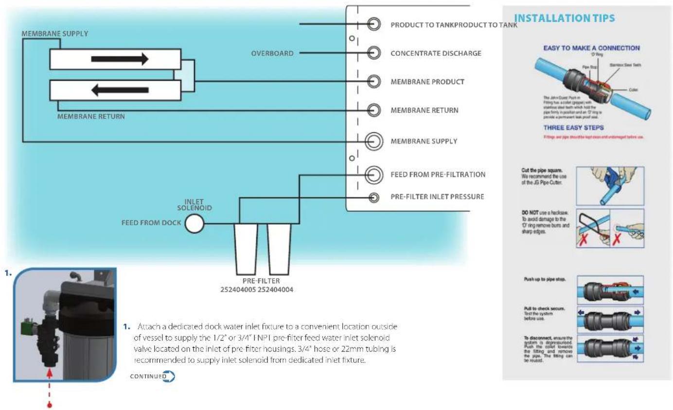
The tubing or piping used for the inlet of the feed water is 1/2" NPT. The tubing or piping used for the discharge of the concentrate is 3/8" O.D. and should be run to an open over board in a free and unrestricted manner.
The tubing or piping used for the product is 3/8" O.D. and can be transported to the holding tank or directly through a high quality nylon tubing or PVC pipe or other FDA accepted materials. Material must not precipitate in the system. Be certain that all of the components of the feed water are soluble at the concentrations attained in the system.
CAUTION: Any restrictions or blockage in the overboard discharge line can cause back pressure, which will increase the system's operating pressure. This can result in damage to the system's components and possible leaks of components or tubing.
ELECTRICAL
The motors used on Spot Zero ^™ systems are pump and motor combinations. They are available in single-phase 115 volt or 230 volt AC. Please ensure that the electrical circuit supplying the system is compatible with the requirements of the specific Spot Zero ^™ model.
PRE-FILTRATION
Spot Zero™ systems are supplied with a sediment pre-filter (part # 252404005) that filters out most particles over 1 microns, a GAC/KDF (part # 252404004) Cartridge that removes chlorine, chloramine, VOCs and heavy metals. CAUTION: a traditional carbon block filter must not be used as it will not remove chloramines and will cause permanent membrane damage. Pre Filters should be changed every 100 hours and/or whenever there is a pressure difference of 15 psi or more between the pressure readings before and after the filter. The pump must NFVR be run dry. Operating the pump without sufficient feed water will damage the pump. ALWAYS feed the pump with filtered water. The pump is susceptible to damage from sediment and debris.
NOTE: THE 252404004 CARTRIDGE MUST BE FLUSHED OUTSIDE OF SYSTEM BEFORE OPERATING TO REMOVE CARBON DUST. The system must be operated on filtered water only. Do not attempt to clean used filter cartridges. The 252404004 is rated to absorb chlorine, chloramine, heavy metals, etc. up to 18,000 gallons of feed water which is the equivalent to approximately 100 hours of run time. CAUTION: If the pre-filter becomes clogged and the water flow to the pump is reduced or interrupted, cavitation will occur. This will damage the pump.

INSTALLATION
flowchart
graph TD
    A["MEMBRANE SUPPLY"] --> B["OVERBOARD"]
    B --> C["MEMBRANE RETURN"]
    C --> D["INLET SOLENOID FEED FROM DOCK"]
    D --> E["PRE-FILTER 252404005 252404004"]
    E --> F["FEED FROM PRE-FILTTRATION"]
    F --> G["PRE-FILTER INLET PRESSURE"]
    G --> H["MEMBRANE RETURN"]
    H --> I["CONCENTRATE DISCHARGE"]
    I --> J["PRODUCT TO TANKPRODUCT TO TANK"]
    J --> K["OPENING LINE"]

ONTINUED FROM PREVIOUS PAGE
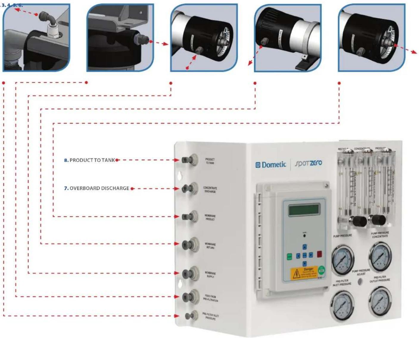
- Attach 1/4" Nylon Spot Zero tubing from "Pre-Filter Inlet Pressure" port on pre-filter housing to "Pre-Filter Inlet Pressure" on Spot Zero Panel.
- Attach 1/2" Nylon Spot Zero tubing from outlet of pre-filter housing to "Feed From Pre-Filtration" on Spot Zero panel.
- Attach 1/2" Nylon Spot Zero tubing from the Spot Zero panel "Membrane Supply" to the "Membrane Supply" fitting on membranes.
- Attach 1/2" Nylon Spot Zero tubing from the "Membrane Return" on membrane fitting to "Membrane Return" on Spot Zero panel.
-
Attach 3/8" Nylon Spot Zero tubing from the "Membrane Product" on membranes to "Membrane Product" on Spot Zero Panel.
-
Attach 3/8" Nylon Spot Zero tubing from the "Concentrate Discharge" on Spot Zero panel and attach the over board line to the concentrate outlet. Water must be allowed to run freely, without any restrictions or blockage in the line. Make sure that no back pressure exists on the concentrate line.
NOTE: There is an internal check valve in the concentrate line in the system.
- Attach 3/8" Nylon Spot Zero tubing from the "Product to Tank" on Spot Zero panel and supply to vessels fresh water tank. Water must be allowed to run freely, without any restrictions or blockage in the line. Make sure that no back pressure exists on the concentrate line.
NOTE: There is an internal check valve in the product line in the system.
NOTE: An optional bacteriostatic remineralizer housing and cartridge may be installed in series with "product to tank" if low pH feed water is anticipated, copper plumbing is used in vessels fresh water system and also should be used upstream of and when a silver ionizer is used for residual sterilization.
2.3.
-
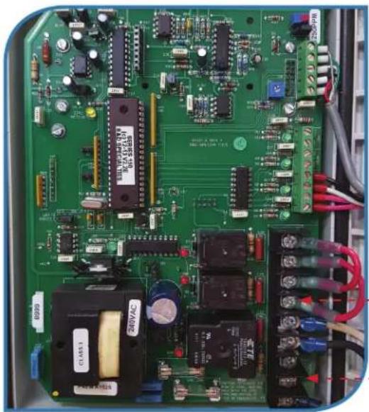
Supply and connect specified power (115v or 230v) from panel to Spot Zero panel and connect to L1 and L2 of PC board. Be sure to confirm systems rated voltage before applying power. Use 12 gauge wire and 20 amp breaker.
-
Supply and connect inlet solenoid valve to "inlet" terminals of PC board. *20 amp breaker is recommended.
natural_image
Close-up of an electronic circuit board with various components and wiring (no readable text or symbols)10.
*Leave jumpers in place.
| S-150 CONTROLLER | S-150 CONTROLLER ENCLOSURE | RO SYSTEM | EXTERNAL BY CUSTOMER |
| ELECTRICAL SYMBOLS | ABBREVIATIONS | WIRE DESCRIPTION | WIRE GAUGE | !#%&1(#%)*!+.-.#(5%/012)'203/4%/%555678889,'#1(#80)9-#. | ||||||||||||
| C | M | OXXO | ++ | MAIN POWER WIRES | 14 AWG | |||||||||||
| COL | MOTOR | OVERLOAD | NO CONTACT | PUMP WIRES | 14 AWG | |||||||||||
| CONTROL WIRES | 22 AWG | TITLE:S-150 120/220VAC 3/4HP 1PH, 50/60HZSPOT ZERO TAP WATER | ||||||||||||||
| NO PRESSURE SWITCH | NC FLOAT SWITCH | No NC CONTACT | ☐ | SOLENOID WIRES | 18 AWG | DWG BY | DATE | SIZEA | DWG NO.ELC-0001-A | REV A | ||||||
| FUSE | ENG APPR. | |||||||||||||||
| MISCELLANEOUS SYMBOLS | QA | SCALE: NONE | SHEET: 1 OF 2 | |||||||||||||
| TERMINAL BLOCK | HC FILTER | GROUND | PUMP | S3WAYSOLENOIDVALVE | TDSCELL | S3WAY3DAYSOLENOIDVALVE | PROPRIETARY AND CONFIDENTIAL:THE INFORMATION CONTAINED IN THE DRAWING IS THE SOLE PROPERTY OF ANION WATER TECHNOLOGY, ANYREPRODUCTS ON THE PART OR AS A SINGLE WITHOUT THE WRITTEN PERMISSION OF ANION WATER TECHNOLOGY ISPROHIBITED.#2011 ANION WATER TECHNOLOGIES | |||||||||
SYSTEM PURGING (initial startup)
NOTE: LEAVE THE POWER TO THE SYSTEM OFF FOR THIS PROCEDURE
- Install 252404005 in first filter housing.
-
Flush the provided 252404004 Filter Cartridge, then install into the second housing. The housing is outside of the system to prevent carbon dust from fouling system membranes.
-
Fully open the concentrate valve (Counter Clockwise). * If your valve is not shown, turn to page 15 for reference.
-
Fully close the recycle valve (Clockwise). * If your valve is not shown, turn to page 15 for reference.
-
Offset inlet solenoid bypass valve.
-
Turn the feed water on and let the system purge until no visible bubbles appear from concentrate flow meter.
-
Restore inlet solenoid valve to normal operating position and refer to operating instructions on next page.
natural_image
3D mechanical component diagram showing a valve assembly with green and black components (no text or symbols)VALVE OPEN (BYPASSFD)
natural_image
3D mechanical component diagram showing a valve assembly with green and black components (no text or symbols)VALVE CLOSED (NORMAL OPERATION)
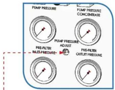
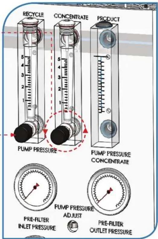
These gauges measure the feed water pressure when it enters and exits the pre-filter housing. A pressure differential of 15 psi or more on the two pressure readings indicates that the pre-filter needs to be replaced. For example, if the inlet pressure is 40 psi the filter should be changed when the outlet pressure is 25 psi or below.
NOTE: Filters must be changed every 100 hours to prevent chlorine and/or chloramine damage to membrane/s.
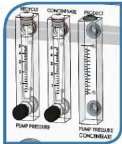
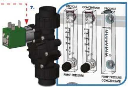
PRODUCT FLOW METER & CONCENTRATE FLOW METER
These flow meters indicate the flow rates of product and concentrate water. The measurements, when added together, also indicate the feed water flow rate.
RECYCLE VALVE
This valve allows you to recycle a portion of the concentrate water back to the feed of the pump. This will increase the recovery of the Spot Zero ^™ system.
STARTUP
- Supply system with a dedicated pressurized municipal fresh water supply.
- When powered up, press the green power button until "Spot Zero Ready" is shown.
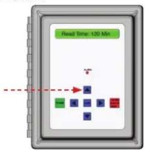
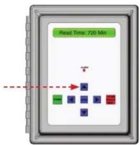
AUTO FLUSH OPTIONS
*With Spot Zero off, press and hold the red button for 10 seconds.
- Press the up arrow one time for each 60 minutes of run time desired up to 12 hours of total run time. System will automatically shut down after timer setting terminates. (CAUTION: Systems with Spot Zero Double Pass™ feature should not use the use of the timer function.)
60 MINUTES 120 MINUTES 720 MINUTES

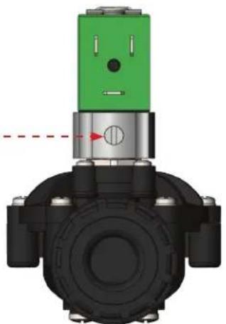
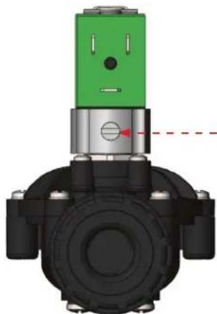
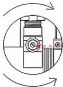
The pump pressure adjustment may be adjusted to reduce or increase flow rates to achieve settings below if necessary. Pump pressure adjustment screw is located between pre filter inlet and outlet pressure gauges on Spot Zero panel and can be adjusted with a #2 flat screwdriver in the location shown below.
NOTE: The product flow rate will decrease as the feed water temperature decreases. Please see below membrane, temperature correction factor chart and examples.
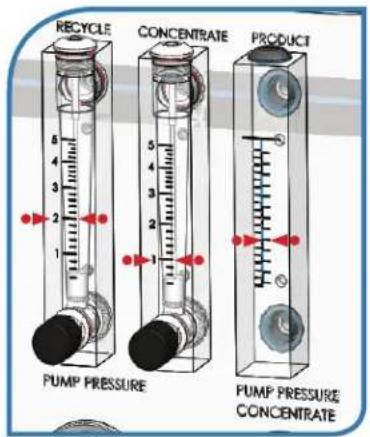
For Spot Zero 2000 (SZ 2000)- Set concentrate and recycle valves to produce specified flow rates of 2 GPM of recycle, 1 GPM of concentrate flow, 1.38 GPM of product @ 77 Degrees F (25 Degrees C).
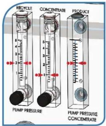
For Spot Zero 3000 (SZ 3000)- Set concentrate and recycle valves to produce specified flow rates of 2 GPM of recycle, 1 GPM of concentrate flow, 2.0 GPM of product @ 77Degrees F (25 Degrees C).
- WARNING: Never exceed the maximum pump pressure (175psi), or production rating of your membrane system, this will prevent premature fouling of the reverse osmosis membrane.
INCREASE FLOW/PRESSURE
natural_image
Diagram of a mechanical device with rotating arrows and a dashed red line, no text or symbols present.DECREASE FLOW PRESSURE
Corrected Flow Rate = (measured flow rate) x TCF (temperature correction factor @ feed water temperature)
EXAMPLE # 1
A Spot Zero 2000 (SZ 2000) is producing 1 GPM of product @ 60 Degrees F 1 GPM x 1.371 TCF = 1.371 GPM of Corrected Flow Rate. (system operating properly, SZ 2000 rated to produce 1.38 GPM)
EXAMPLE #2
Spot Zero 3000 (SZ 3000) is producing 1.25 GPM @ 50 Degrees F 1.2 GPM x 1.7 TCF = 2.04 GPM of Corrected Flow Rate. (system operating property, SZ 3000 rated to produce 2.0 GPM)
EXAMPLE # 3
Spot Zero 2000 (SZ 2000) is producing 0.9 GPM @ 77 Degrees F 0.9GPM x 1.0 TCF = 0.9 GPM of Corrected Flow Rate (system is not producing water properly, increase pump pressure or cleaning of membrane/s may be required)
| Temperature°F (°C) | TemperatureCorrectionFactor | Temperature°F (°C) | TemperatureCorrectionFactor | Temperature°F (°C) | TemperatureCorrectionFactor | Temperature°F (°C) | TemperatureCorrectionFactor | Temperature°F (°C) | TemperatureCorrectionFactor |
| 50.0 (10.0) | 1.711 | 57.2 (14.0) | 1.475 | 64.4 (18.0) | 1.276 | 71.6 (22.0) | 1.109 | 78.8 (26.0) | 0.971 |
| 50.2 (10.1) | 1.705 | 57.4 (14.1) | 1.469 | 64.6 (18.1) | 1.272 | 71.8 (22.1) | 1.105 | 79.0 (26.1) | 0.968 |
| 50.4 (10.2) | 1.698 | 57.6 (14.2) | 1.464 | 64.8 (18.2) | 1.267 | 72.0 (22.2) | 1.101 | 79.2 (26.2) | 0.965 |
| 50.5 (10.3) | 1.692 | 57.7 (14.3) | 1.459 | 64.9 (18.3) | 1.262 | 72.1 (22.3) | 1.097 | 79.3 (26.3) | 0.962 |
| 50.7 (10.4) | 1.686 | 57.9 (14.4) | 1.453 | 65.1 (18.4) | 1.258 | 72.3 (22.4) | 1.093 | 79.5 (26.4) | 0.959 |
| 50.9 (10.5) | 1.679 | 58.1 (14.5) | 1.448 | 65.3 (18.5) | 1.254 | 72.5 (22.5) | 1.090 | 79.7 (26.5) | 0.957 |
| 51.1 (10.6) | 1.673 | 58.3 (14.6) | 1.443 | 65.5 (18.6) | 1.249 | 72.7 (22.6) | 1.086 | 79.9 (26.6) | 0.954 |
| 51.3 (10.7) | 1.667 | 58.5 (14.7) | 1.437 | 65.7 (18.7) | 1.245 | 72.9 (22.7) | 1.082 | 80.1 (26.7) | 0.951 |
| 51.4 (10.8) | 1.660 | 58.6 (14.8) | 1.432 | 65.8 (18.8) | 1.240 | 73.0 (22.8) | 1.078 | 80.2 (26.8) | 0.948 |
| 51.6 (10.9) | 1.654 | 58.8 (14.9) | 1.427 | 66.0 (18.9) | 1.236 | 73.2 (22.9) | 1.075 | 80.4 (26.9) | 0.945 |
| 51.8 (11.0) | 1.648 | 59.0 (15.0) | 1.422 | 66.2 (19.0) | 1.232 | 73.4 (23.0) | 1.071 | 80.6 (27.0) | 0.943 |
| 52.0 (11.1) | 1.642 | 59.2 (15.1) | 1.417 | 66.4 (19.1) | 1.227 | 73.6 (23.1) | 1.067 | 80.8 (27.1) | 0.940 |
| 52.2 (11.2) | 1.636 | 59.4 (15.2) | 1.411 | 66.6 (19.2) | 1.223 | 73.8 (23.2) | 1.064 | 81.0 (27.2) | 0.937 |
| 52.3 (11.3) | 1.630 | 59.5 (15.3) | 1.406 | 66.7 (19.3) | 1.219 | 73.9 (23.3) | 1.060 | 81.1 (27.3) | 0.934 |
| 52.5 (11.4) | 1.624 | 59.7 (15.4) | 1.401 | 66.9 (19.4) | 1.214 | 74.1 (23.4) | 1.056 | 81.3 (27.4) | 0.932 |
| 52.7 (11.5) | 1.618 | 59.9 (15.5) | 1.396 | 67.1 (19.5) | 1.210 | 74.3 (23.5) | 1.053 | 81.5 (27.5) | 0.929 |
| 52.9 (11.6) | 1.611 | 60.1 (15.6) | 1.391 | 67.3 (19.6) | 1.206 | 74.5 (23.6) | 1.049 | 81.7 (27.6) | 0.926 |
| 53.1 (11.7) | 1.605 | 60.3 (15.7) | 1.386 | 67.5 (19.7) | 1.201 | 74.7 (23.7) | 1.045 | 81.9 (27.7) | 0.924 |
| 53.2 (11.8) | 1.600 | 60.4 (15.8) | 1.381 | 67.6 (19.8) | 1.197 | 74.8 (23.8) | 1.042 | 82.0 (27.8) | 0.921 |
| 53.4 (11.9) | 1.594 | 60.6 (15.9) | 1.376 | 67.8 (19.9) | 1.193 | 75.0 (23.9) | 1.038 | 82.2 (27.9) | 0.918 |
| 62.6 (12.0) | -1.688 | 60.8 (16.0) | 1.371 | 68.0 (20.0) | 1.189 | 75.2 (24.0) | 1.035 | 82.4 (28.0) | 0.915 |
| 53.8 (12.1) | 1.582 | 61.0 (16.1) | 1.366 | 68.2 (20.1) | 1.185 | 75.4 (24.1) | 1.031 | 82.6 (28.1) | 0.913 |
| 54.0 (12.2) | 1.576 | 61.2 (16.2) | 1.361 | 68.4 (20.2) | 1.180 | 75.6 (24.2) | 1.028 | 82.8 (28.2) | 0.910 |
| 54.1 (12.3) | 1.570 | 61.3 (16.3) | 1.356 | 68.5 (20.3) | 1.176 | 75.7 (24.3) | 1.024 | 82.9 (28.3) | 0.908 |
| 54.3 (12.4) | 1.564 | 61.5 (16.4) | 1.351 | 68.7 (20.4) | 1.172 | 75.9 (24.4) | 1.021 | 83.1 (28.4) | 0.905 |
| 54.5 (12.5) | 1.558 | 61.7 (16.5) | 1.347 | 68.9 (20.5) | 1.168 | 76.1 (24.5) | 1.017 | 83.3 (28.5) | 0.902 |
| 54.7 (12.6) | 1.553 | 61.9 (16.6) | 1.342 | 69.1 (20.6) | 1.164 | 76.3 (24.6) | 1.014 | 83.5 (28.6) | 0.900 |
| 54.9 (12.7) | 1.547 | 62.1 (16.7) | 1.337 | 69.3 (20.7) | 1.160 | 76.5 (24.7) | 1.010 | 83.7 (28.7) | 0.897 |
| 55.0 (12.8) | 1.541 | 62.2 (16.8) | 1.332 | 69.4 (20.8) | 1.156 | 76.6 (24.8) | 1.007 | 83.8 (28.8) | 0.894 |
| 55.2 (12.9) | 1.536 | 62.4 (16.9) | 1.327 | 69.6 (20.9) | 1.152 | 76.8 (24.9) | 1.003 | 84.0 (28.9) | 0.892 |
| 65.4 (13.0) | -1.636 | 62.6 (17.0) | -1.329 | 69.8 (24.0) | -1.148 | 77.0 (25.0) | 1.000 | 84.2 (29.0) | 0.889 |
MEMBRANE PERFORMANCE CHECK INSTRUCTIONS
- To properly check membrane performance, completely close recycle valve by turning clockwise until no water flow is shown in flow meter. Open concentrate valve completely until 3 GPM or more is shown in Concentrate flow meter.
- With a handheld IDS meter, record a reading of the dock water feed PPM of IDS.
- After at least 3 minutes of operation, record a reading of the product water PPM of TDS on the Spot Zero display.
- Membrane Rejection – Feed Water Parts Per Million (PPM) of Total Dissolved Solids (TDS) - Product Water PPM Feed Water PPM of TDS
EXAMPLE: (117 ppm of Feed Water - 4 ppm of Product Water) = 113 ppm / 117 ppm of Feed TDS
113ppm/117ppm = 96.58 % Rejection
NOTE: Rejection Rates above 94% @ 77 Deg. I indicate acceptable membrane performance. NOTE: To get best results from the system, change membranes every 1,000 hours. Bo aware of an x10 showing up in the upper right corner of the TDS meter indicating very high ppm water.


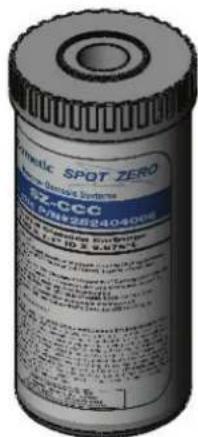
MEMBRANE CHEMICAL CLEANING PROCEDURE
When membrane performance is reduced and is not due to temperature or feed water quality, a chemical cleaning may be required to remove scaling of membrane film.
NOTE: Damage to membrane film caused by chlorine or chloramine is irreversible and cannot be corrected by chemical cleaning.
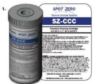
- Procure as Part # SZ-CCC (Spot Zero Chemical Cleaning Cartridge).
- Turn System off.
- Disconnect product to tank and discard any product during cleaning process.
- Temporarily Install SZ-10KDF2 in first housing in place of SZ-45-1001.
- Insert SZ-CCC in second housing in place of SZ-10KDF2.
- Open concentrate valve counter clockwise until fully open.
- Open feed solenoid valve manually via solenoid bypass valve with feed water present for 2 minutes or until concentrate flow meter shows signs of discoloration. Close bypass on feed solenoid valve.
- Allow membranes to soak for 2 hours. For heavily scaled membranes, soak for 24 hours.
- After 2-24 hours soak time, re-open bypass on solenoid to allow system to flush for 30 minutes while machine is off.
- Return SZ 45-1001 filter to first housing and SZ-10KDF2 to second housing and return system to normal operation.
For Spot Zero 2000 (SZ 2000)- Set concentrate and recycle valves to produce specified flow rates of:
2 GPM of recycle, 1 GPM of concentrate flow, 1.38 GPM of product @ 77 Degrees F (25 Degrees C)
For Spot Zero 3000 (SZ 3000)- Set concentrate and recycle valves to produce specified flow rates of:
2 GPM of recycle, 1 GPM of concentrate flow, 2.0 GPM of product @ 77Degrees F (25 Degrees C) Membrane Removal & Replacement
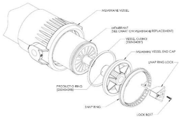
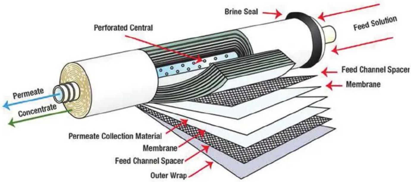
Changing membranes in pressure vessels is an easy process if you have the proper information and tools at hand. Please refer to the following instructions when removing and replacing membrane elements:
NOTE: The system must be off.
- Locate the inlet end of the pressure vessel, that is opposite the flow direction.
- Remove the screw from the yellow snap ring lock at the end of the pressure vessel.
- Remove the white Nylon snap ring from the end cap.
- Remove the end cap from the pressure vessel.
natural_image
Exploded view diagram of a mechanical assembly showing internal components and assembly steps (no text or labels)-
Slowly remove the membrane element from the pressure vessel being careful not to grasp it by the permeate tube. Needle nose pliers may be necessary to pull the old membrane element out of the pressure vessel.
-
Remove new membrane element from container and inspect. Make sure that all parts are clean and free from dirt. Examine the brine seal, and permeate tube for nicks or cuts. Replace the O-rings or brine seal if damaged.
-
Lubricate the brine seal with a food grade lubricant.
-
Install the membrane element so the brine seal will be located and the opposite end of the flow direction.
-
At a slight angle insert membrane while slightly rotating element being careful not to tear or flip the brine seal. Re-lube the brine seal if necessary.
-
With a smooth and constant motion, push the membrane element into the housing so that the brine seal enters the housing without coming out of the brine seal groove. A slow twisting motion should be used to insert the membrane element, to ensure that the brine seal stays in place.
-
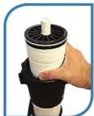
Re-install the end caps by gently twisting the end cap while pushing it onto the housing. Ensure that you do not pinch or fatigue any O rings while pushing the end plug on. Push the end plug on until the outer diameter of the plug is flush with the outer diameter of the membrane housing. (A rubber mallet may be necessary).
-
Re-install the white nylon snap ring and the yellow snap ring lock
-
These directions should be observed for installation of each element in each housing.
NOTE: As time progresses, the efficiency of the membrane will be reduced. The permeate flow rate will begin to decline slightly after one year of operation, but can be extended with diligent flushing and cleaning of the system. A high pH and/or precipitation of hardness can cause premature loss in rejection of membrane elements in the system.
NOTE: To get best results from the system change membranes every 1,000 hours.
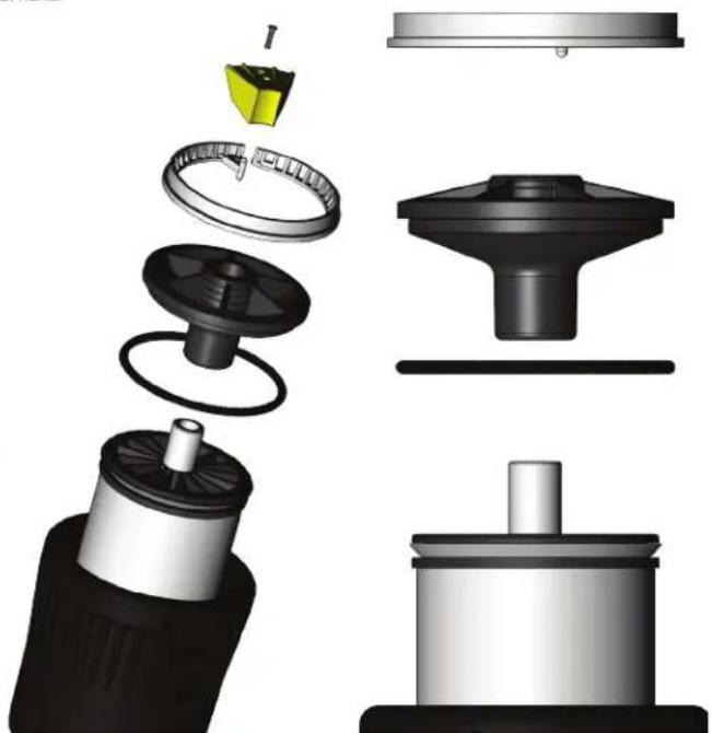
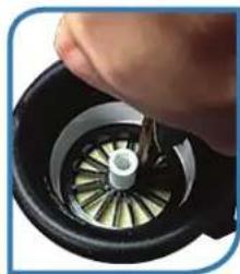
MEMBRANE IDENTIFICATION
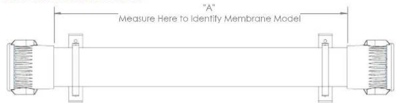

Correct Incorrect
5.
natural_image
Close-up of a hand turning a mechanical component with a metallic gear and central hub (no visible text or symbols)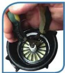
natural_image
Close-up of a hand holding a mechanical component with a circular dial and green blades (no visible text or symbols)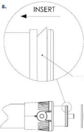
natural_image
Hand holding a white cylindrical object with black spool, no visible text or symbolsSEAL DIRECTION
WEEKLY MAINTENANCE
A weekly high volume feed flush can greatly improve systems performance by releasing any precipitation of scale and/or sediment buildup on membrane film surface area. The use of feed water is acceptable, the use of Spot Zero purified product water from vessels fresh water system is preferred.
- Supply dock feed or pressurized fresh water feed from vessel to dedicated Spot Zero inlet connection.
- Turn System on and completely open concentrate valve counter clockwise.
- Completely close recycle valve.
- Allow unit to run for 5-10 minutes
- Restore system to normal operating flow rates.
- Do change filter cartridges (SZ-45-1001 & SZ-10KDF2) every 100 hours to prevent membrane damage.
- Do run the system often.
- Do confirm that recycle flow rate is at 2 GPM during normal operation.
- Do confirm that concentrate flow rate is at 1 GPM during normal operation.
- Do perform weekly system flush.
- Do change membranes every 1,000 hours.
Do Not
- Do Not re-use filter cartridges.
- Do Not produce more product than system is rated for.
- Do Not run machine without water supply.
- Do Not use unapproved pre-filter cartridges, membrane damage may occur.
- Do Not leave system un-used for long periods of time.
- Do Not expose system to temperatures below 32 degrees F (0 Degrees C).
- Do Not leave system unattended while operating.
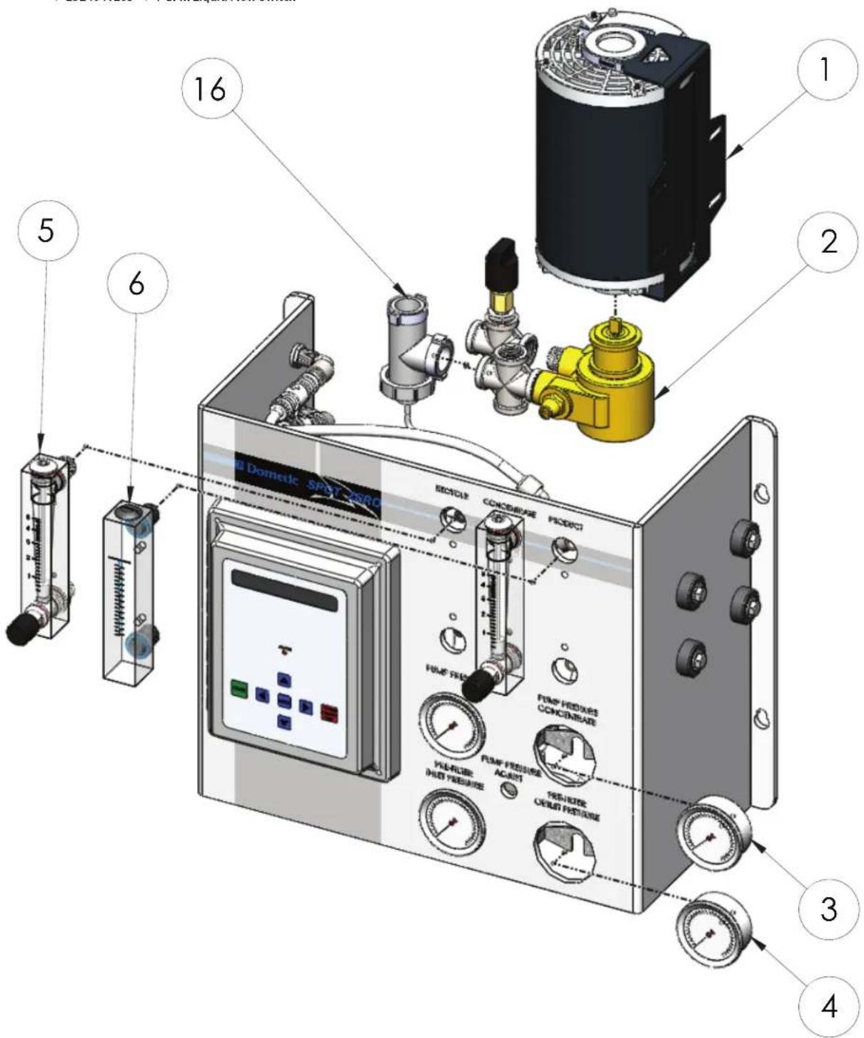
SPOT ZERO UNIT SPARE PARTS
| Item Number | Part # | Description |
| 1 | 252404026 | 3/4 HP Single PH Motor |
| 2 | 252404143 | 5.3 GPM Vane Pump |
| 3 | 252404024 | 0-300 PSI Gauge |
| 4 | 252404027 | 0-100 PSI Gauge |
| 5 | 252404030 | Flow Meter W/Valve |
| 6 | 252404031 | Flow Meter W/O Valve |
| 16 | 2524041265 | 1 GPM Liquid Flow Switch |
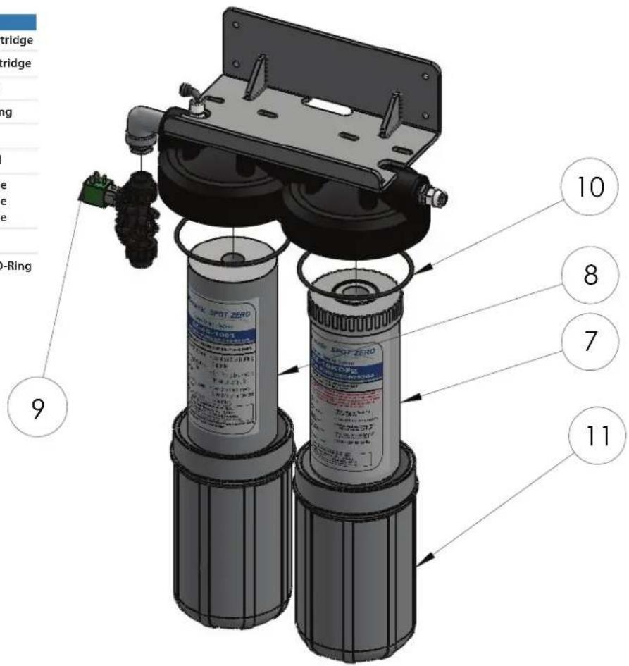
SPOT ZERO UNIT SPARE PARTS
| Item Number | Part # | Description |
| 7 | 252404004 | SZ-45-1001 Spot Zero Cartridge |
| 8 | 252404005 | SZ-10KDF2 Spot Zero Cartridge |
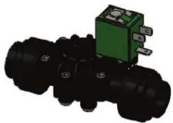
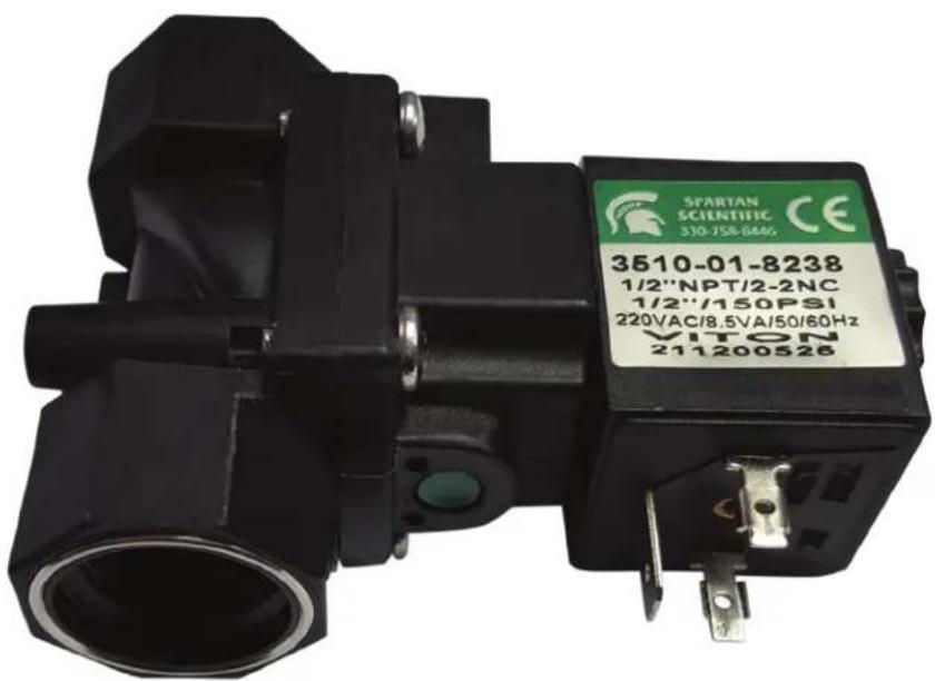
| 9 | SEE DWG SZ0038 | 2-Way/NC Solenoid Valve |
| 10 | 252404127 | O-Ring For 4.5 x 10 Housing |
| 11 | 252404302 | 4.5 x 10 Filter Housing |
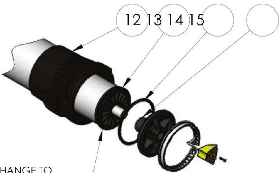
| 12 | 252404173 | Spot Zero Upgrade Vessel |
| 13 | 252404000 | Spot Zero 4039 Membrane |
| 252404188 | Spot Zero 4040 Membrane | |
| 252404184 | Spot Zero 4021 Membrane | |
| 14 | 252404097 | 4" Membrane O-Ring |
| 15 | 252404098 | 1/2" Membrane Product O-Ring |
SEE MANUAL
MEMBRANE CHANGE TO
IDENTIFY MEMBRANE PART#
12 13 14 15
SPOT ZERO UNIT SPARE PARTS
Inlet Solenoid 2-Way
252404028-FOR 115V 25204029-FOR 230V
natural_image
3D rendering of a black mechanical component with a green internal component (no text or symbols visible)2.5 x 10 Filter Wrench
252404049

natural_image
3D rendered image of a mechanical tool handle with circular grooves and square cutouts (no text or symbols)2.5 x 10 Filter Housing O-Ring
252404049

Hand Held TDS
252404040

natural_image
3D rendering of a blue handheld electronic device with control buttons and a display screen (no text or symbols visible)4.5 x 10 Filter Wrench
252404090

natural_image
3D rendered image of a black circular mechanical component with a handle and mounting holes (no text or symbols)4.5 x 10 Filter Housing O-Ring
252404147

natural_image
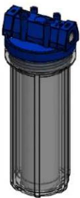
Simple black oval shape on white background (no text or symbols)2.5 x 10 Filter Housing
252404304
252404302
Cartridge
252404141
252404006
4.5 x 10 Filter Housing
Bacteriostatic Remineralizer
Chemical Cleaning Cartridge
natural_image
3D rendering of a cylindrical industrial container with blue top and gray internal structure (no text or symbols)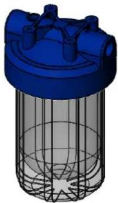
natural_image
3D rendering of a blue industrial filter or separator with mesh structure (no text or symbols)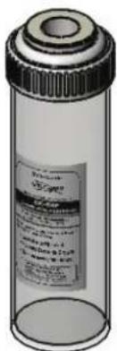
SYSTEM PURGING (initial startup)
* Page 8 reference for Solenoid Valve not shown.
REVERSE OSMOSIS - HOW DOES IT WORK
Reverse osmosis (RO) is a separation process that uses pressure to force a solvent through a membrane that retains the solute on one side and allow the pure solvent to pass to the other side. More formally, it is the process of forcing a solvent from a region of high solute concentration through a membrane to a region of low solute concentration by applying a pressure. This is the reverse of the normal osmosis process, which is the natural movement of solvent from an area of low solute concentration, through a membrane, to an area of high solute concentration when no external pressure is applied. The membrane here is semipermeable, meaning it allows the passage of solvent but not of soluble.
REVERSE OSMOSIS TROUBLESHOOTING
SYMPTOMS POSSIBLE CAUSES CORRECTIVE ACTION
| LP FAULTrecommended for pre-filter outlet pressure during operation. | Low dock supply pressure | Increase Inlet Pressure. A minimum of 25psi is | |
Car | Change Filters | ||
| Solenoid valve malfunction | Replace Sol. Valve and/or Coil | ||
| Leaks | Fix any visible leaks | ||
| LOW PERMEATE FLOW | Cold feed water | See temperature correction sheet | |
 | Low operating pressure | Adjust throttle and concentrate valve | |
| Defective membrane brine seal/Membrane installed backwards | Replace brine seal and / or Reposition membranes | ||
| I ouled or Scaled membrane | Clean membranes | ||
| Damaged product tube o-rings | Inspect and/or replace | ||
| HIGH PERMEATE FLOW |  | Damaged or oxidized membrane | Replace membrane |
| Exceeding maximum feed water temperature | See temperature correction sheet | ||
| Low operating pressure | Adjust concentrate valve | ||
| POOR PERMEATE QUALITY |  | Damage product tube o-rings | Inspect and/or replace |
| Damaged or oxidized membrane from Chlorine or Chloramine in feed water | Replace membrane and be sure that SZ-10KDF2 is changed every 100 hours. | ||
| MEMBRANE FOULING | Scaling (CaSO4, CaSO3, BaSO4, SiO2) over production, conduct weekly maintenance flush. | Clean with SZ-CCC Cleaning Cartridge. Check for | |
| Trapped sediment media | Replace Membrane, check pre-filtration | ||
| Chlorine OxidationBe sure that SZ-10KDI 2 is replaced every 100 hours. | Check Chlorine feed equipment and de-chlorination system. | ||
| HIGH PUMP PRESSURE (<150 PSI) | Cold feed water | See temperature correction sheet | |
| Membrane Fouling | See Membrane Fouling | ||
MEMBRANE ELEMENT ION REJECTION RATES
TFC MEMBRANES
CHARACTERISTICS OF THIN FILM COMPOSITE POLYAMIDE MEMBRANE
| Ion | Symbol | % Rejection |
| Aluminum | Al+3 | 97 – 98 |
| Ammonium | NH_4^+ | 85 – 95 |
| Borate | B_4O_2^-2 | 30 – 50 |
| Boron | B | 60 – 70 |
| Bromide | Br - | 93 – 96 |
| Cadmium | Cd^+2 | 93 – 97 |
| Calcium | Ca^+2 | 95 – 98 |
| Chloride | Cl - | 92 – 98 |
| Chromate | CrO_4^-2 | 85 – 95 |
| Copper | Cu^+2 | 96 – 98 |
| Fluoride | F - | 93 – 95 |
| Iron | Fe^+2 | 96 – 98 |
| Lead | Pb^+2 | 95 – 98 |
| Manganese | Mn^+2 | 97 – 98 |
*Nominal Rejection* Nominal Rejection
| Ion | Symbol | % Rejection |
| Magnesium | Mg^2+ | 95 - 98 |
| Mercury | Hg^2+ | 95 - 97 |
| Nickel | Ni^2+ | 97 - 98 |
| Nitrate | NO_3^- | 90 - 95 |
| Phosphate | PO_4^3- | 95 - 98 |
| Polyphosphate | 96 - 98 | |
| Potassium | K^+ | 92 - 96 |
| Silica | Si | 85 - 90 |
| Silicate | SiO_2^2- | 92 - 95 |
| Silver | Ag^+ | 95 - 97 |
| Sodium | Na^+ | 92 - 98 |
| Sulfate | SO_4^2- | 96 - 98 |
| Thiosulfate | S_2O_3^2- | 97 - 98 |
| Zinc | Zn^2+ | 97 - 99 |
*The above percent of rejection is for reference only and not to be construed as chemistry. Temperature and TDS are not constant in each water supply.
CONTINUED FROM PAGE 9
| Temperature °F (°C) | Temperature Correction Factor | Temperature °F (°C) | Temperature Correction Factor | Temperature °F (°C) | Temperature Correction Factor | Temperature °F (°C) | Temperature Correction Factor | Temperature °F (°C) | Temperature Correction Factor |
| 50.0 (10.0) | 1.711 | 57.2 (14.0) | 1.475 | 64.4 (18.0) | 1.276 | 71.6 (22.0) | 1.109 | 78.8 (26.0) | 0.971 |
| 50.2 (10.1) | 1.705 | 57.4 (14.1) | 1.469 | 64.6 (18.1) | 1.272 | 71.8 (22.1) | 1.105 | 79.0 (26.1) | 0.968 |
| 50.4 (10.2) | 1.698 | 57.6 (14.2) | 1.464 | 64.8 (18.2) | 1.267 | 72.0 (22.2) | 1.101 | 79.2 (26.2) | 0.965 |
| 50.5 (10.3) | 1.692 | 57.7 (14.3) | 1.459 | 64.9 (18.3) | 1.262 | 72.1 (22.3) | 1.097 | 79.3 (26.3) | 0.962 |
| 50.7 (10.4) | 1.686 | 57.9 (14.4) | 1.453 | 65.1 (18.4) | 1.258 | 72.3 (22.4) | 1.093 | 79.5 (26.4) | 0.959 |
| 50.9 (10.5) | 1.679 | 58.1 (14.5) | 1.448 | 65.3 (18.5) | 1.254 | 72.5 (22.5) | 1.090 | 79.7 (26.5) | 0.957 |
| 51.1 (10.6) | 1.673 | 58.3 (14.6) | 1.443 | 65.5 (18.6) | 1.249 | 72.7 (22.6) | 1.086 | 79.9 (26.6) | 0.954 |
| 51.3 (10.7) | 1.667 | 58.5 (14.7) | 1.437 | 65.7 (18.7) | 1.245 | 72.9 (22.7) | 1.082 | 80.1 (26.7) | 0.951 |
| 51.4 (10.8) | 1.660 | 58.6 (14.8) | 1.432 | 65.8 (18.8) | 1.240 | 73.0 (22.8) | 1.078 | 80.2 (26.8) | 0.948 |
| 51.6 (10.9) | 1.654 | 58.8 (14.9) | 1.427 | 66.0 (18.9) | 1.236 | 73.2 (22.9) | 1.075 | 80.4 (26.9) | 0.945 |
| 51.8 (11.0) | 1.648 | 59.0 (15.0) | 1.422 | 66.2 (19.0) | 1.232 | 73.4 (23.0) | 1.071 | 80.6 (27.0) | 0.943 |
| 52.0 (11.1) | 1.642 | 59.2 (15.1) | 1.417 | 66.4 (19.1) | 1.227 | 73.6 (23.1) | 1.067 | 80.8 (27.1) | 0.940 |
| 52.2 (11.2) | 1.636 | 59.4 (15.2) | 1.411 | 66.6 (19.2) | 1.223 | 73.8 (23.2) | 1.064 | 81.0 (27.2) | 0.937 |
| 52.3 (11.3) | 1.630 | 59.5 (15.3) | 1.406 | 66.7 (19.3) | 1.219 | 73.9 (23.3) | 1.060 | 81.1 (27.3) | 0.934 |
| 52.5 (11.4) | 1.624 | 59.7 (15.4) | 1.401 | 66.9 (19.4) | 1.214 | 74.1 (23.4) | 1.056 | 81.3 (27.4) | 0.932 |
| 52.7 (11.5) | 1.618 | 59.9 (15.5) | 1.396 | 67.1 (19.5) | 1.210 | 74.3 (23.5) | 1.053 | 81.5 (27.5) | 0.929 |
| 52.9 (11.6) | 1.611 | 60.1 (15.6) | 1.391 | 67.3 (19.6) | 1.206 | 74.5 (23.6) | 1.049 | 81.7 (27.6) | 0.926 |
| 53.1 (11.7) | 1.605 | 60.3 (15.7) | 1.386 | 67.5 (19.7) | 1.201 | 74.7 (23.7) | 1.045 | 81.9 (27.7) | 0.924 |
| 53.2 (11.8) | 1.600 | 60.4 (15.8) | 1.381 | 67.6 (19.8) | 1.197 | 74.8 (23.8) | 1.042 | 82.0 (27.8) | 0.921 |
| 53.4 (11.9) | 1.594 | 60.6 (15.9) | 1.376 | 67.8 (19.9) | 1.193 | 75.0 (23.9) | 1.038 | 82.2 (27.9) | 0.918 |
^ F = ( ^ C × 9/5) + 32
| Temperature °F (°C) | Temperature Correction Factor | Temperature °F (°C) | Temperature Correction Factor | Temperature °F (°C) | Temperature Correction Factor | Temperature °F (°C) | Temperature Correction Factor | Temperature °F (°C) | Temperature Correction Factor |
| 53.6 (12.0) | 1.588 | 60.8 (16.0) | 1.371 | 68.0 (20.0) | 1.189 | 75.2 (24.0) | 1.035 | 82.4 (28.0) | 0.915 |
| 53.8 (12.1) | 1.582 | 61.0 (16.1) | 1.366 | 68.2 (20.1) | 1.185 | 75.4 (24.1) | 1.031 | 82.6 (28.1) | 0.913 |
| 54.0 (12.2) | 1.576 | 61.2 (16.2) | 1.361 | 68.4 (20.2) | 1.180 | 75.6 (24.2) | 1.028 | 82.8 (28.2) | 0.910 |
| 54.1 (12.3) | 1.570 | 61.3 (16.3) | 1.356 | 68.5 (20.3) | 1.176 | 75.7 (24.3) | 1.024 | 82.9 (28.3) | 0.908 |
| 54.3 (12.4) | 1.564 | 61.5 (16.4) | 1.351 | 68.7 (20.4) | 1.172 | 75.9 (24.4) | 1.021 | 83.1 (28.4) | 0.905 |
| 54.5 (12.5) | 1.558 | 61.7 (16.5) | 1.347 | 68.9 (20.5) | 1.168 | 76.1 (24.5) | 1.017 | 83.3 (28.5) | 0.902 |
| 54.7 (12.6) | 1.553 | 61.9 (16.6) | 1.342 | 69.1 (20.6) | 1.164 | 76.3 (24.6) | 1.014 | 83.5 (28.6) | 0.900 |
| 54.9 (12.7) | 1.547 | 62.1 (16.7) | 1.337 | 69.3 (20.7) | 1.160 | 76.5 (24.7) | 1.010 | 83.7 (28.7) | 0.897 |
| 55.0 (12.8) | 1.541 | 62.2 (16.8) | 1.332 | 69.4 (20.8) | 1.156 | 76.6 (24.8) | 1.007 | 83.8 (28.8) | 0.894 |
| 55.2 (12.9) | 1.536 | 62.4 (16.9) | 1.327 | 69.6 (20.9) | 1.152 | 76.8 (24.9) | 1.003 | 84.0 (28.9) | 0.892 |
| 55.4 (13.0) | 1.530 | 62.6 (17.0) | 1.323 | 69.8 (21.0) | 1.148 | 77.0 (25.0) | 1.000 | 84.2 (29.0) | 0.889 |
| 55.6 (13.1) | 1.524 | 62.8 (17.1) | 1.318 | 70.0 (21.1) | 1.144 | 77.2 (25.1) | 0.997 | 84.4 (29.1) | 0.887 |
| 55.8 (13.2) | 1.519 | 63.0 (17.2) | 1.313 | 70.2 (21.2) | 1.140 | 77.4 (25.2) | 0.994 | 84.6 (29.2) | 0.884 |
| 55.9 (13.3) | 1.513 | 63.1 (17.3) | 1.308 | 70.3 (21.3) | 1.136 | 77.5 (25.3) | 0.991 | 84.7 (29.3) | 0.882 |
| 56.1 (13.4) | 1.508 | 63.3 (17.4) | 1.304 | 70.5 (21.4) | 1.132 | 77.7 (25.4) | 0.988 | 84.9 (29.4) | 0.879 |
| 56.3 (13.5) | 1.502 | 63.5 (17.5) | 1.299 | 70.7 (21.5) | 1.128 | 77.9 (25.5) | 0.985 | 85.1 (29.5) | 0.877 |
| 56.5 (13.6) | 1.496 | 63.7 (17.6) | 1.294 | 70.9 (21.6) | 1.124 | 78.1 (25.6) | 0.982 | 85.3 (29.6) | 0.874 |
| 56.7 (13.7) | 1.491 | 63.9 (17.7) | 1.290 | 71.1 (21.7) | 1.120 | 78.3 (25.7) | 0.979 | 85.5 (29.7) | 0.871 |
| 56.8 (13.8) | 1.486 | 64.0 (17.8) | 1.285 | 71.2 (21.8) | 1.116 | 78.4 (25.8) | 0.977 | 85.6 (29.8) | 0.869 |
| 57.0 (13.9) | 1.480 | 64.2 (17.9) | 1.281 | 71.4 (21.9) | 1.112 | 78.6 (25.9) | 0.974 | 85.8 (29.9) | 0.866 |
Corrected Flow Rate = (Measured Flow Rate) * (TCF @ Feed Water Temp.)
*Leave jumpers in place.
line
PROPRIETARY AND CONFIDENTIAL: THIS INFORMATION CONTAINED IN THE DRAWING IS THE SOLE PROPERTY OF SPOT ZERO*. ANY REPRODUCTION IN PART OR AS A WHOLE WITHOUT THE WRITTEN PERMISSION OF SPOT ZERO* IS PROHIBITED.
NOTE: 1 Micron (1 X 10.6 Meters) = 4 X 10.5 Inches (0.00004 Inches)
1 Angstrom Unit = 10.10 Meters = 10.4 Micrometers (Microns)
Dometic
SPOTZERO
The 150 controller is a state of the art control system for commercial and industrial reverse osmosis systems. The Series 150 combines features that have not previously been available in one compact unit.
The Series 150 is a microprocessor controlled system that can monitor pressure and level switches. A IDS / Conductivity monitor/controller with programmable Setpoints is an integral part of the Series 150. The Series 150 displays system status and sensor and switch input status on an easy to read back lit display. User programmable Setpoints are provided that allow fast and easy adjustment of system parameters.
SPECIFICATIONS
POWER:
85-265 VAC, 50/60Hz, 25Watts
ENVIRONMENT:
22°F to 140°F, 0-95% RH, noncondensing
ENCLOSURE:
8" X 6" X 4" (203mm X 152mm X 102mm) NEMA 4X
DISPLAY:
2 line X 20 character, alphanumeric backlit LCD
FRONT PANEL:
Overlay with LCD window, alarm lamp, 7 key membrane switch
SWITCH INPUTS, DRY CONTACT:
Pressure fault
Pretreat lockout
Tank full high
Tank full low
RELAY OUTPUTS:
RO pump relay 120/240VAC, THP
Inlet valve relay 120/240VAC, 5A
Flush valve relay 120/240VAC, 5A
Relays supply same output voltage as board power(120 or 240 VAC)
CELL: TDS / Conductivity cell with digital display, permeate standard range, 0-250PPM or uS. Other ranges available.
PERMEATE: 50, 100, 500, 1000, 2500, 5000.
OPTIONAL FEED: 50, 100, 500, 1000, 2500, 5000, 10000.
Wetted parts ABS and 316SS, 3/4" NPT, 300 PSI max.
OPTIONAL I/O EXPANDER:
Auxiliary/divert/boost relay 120/240VAC, 1HP
Divert/alarm relay 120/240VAC,5A
Tank low switch input, dry contact
FRONT PANEL CONTROLS AND INDICATORS
DISPLAY Shows status of system.
ALARM LAMP Flashes when fault causes an RO system shut down.
On steady when a Setpoint is exceeded that does
not cause an RO system shut down.
POWER KEY Places controller in operating or standby mode.
LEFT ARROW KEY Scrolls through Setpoints starting with first Setpoint.
RIGHT ARROW KEY Scrolls through Setpoints starting with last Setpoint.
UP ARROW KEY Increases value of Setpoint.
DOWN ARROW KEY Decreases value of Setpoint
ENTER KEY Confirms entry of new Setpoint value.
ALARM SILENCE/RESET KEY Push once for alarm silence and twice to reset system after a shut down has occurred.

PHYSICAL INSTALLATION
Mount The Series 150 in a convenient location on the RO equipment using the four mounting ears provided with the unit or the optional panel mounting bracket.
NOTE: All terminals on the board are labeled.
TERMINAL STRIP, JUMPER AND ADJUSTMENT LOCATIONS
Refer to figure 2 (p.30) for the location of all terminal strips and connectors. Figure 2 also shows all jumper and adjustment locations. Figure 3 shows a sample wiring diagram.
POWER WIRING
Refer to figure 2-3 (p.18-19) for terminal strip locations. AC power for the unit is connected to terminal strip P1. Connect the ground wire of the AC power to the terminal labeled GND. For AC power with a neutral and hot wire, the hot wire connects to L1 and the neutral wire connects to L2. For AC power with 2 hot wires, either wire can connect to L1 and L2. On AC power with 2 hot wires, the wire jumper between P6 and P7 should be removed and a fuse(GMA 1/4A) installed in F2.
PUMP AND VALVE RELAY OUTPUTS
The Series 150 supplies relay outputs to control the RO pump and solenoid valves.
NOTE: The relays output the same voltage as the AC power to the board. If the pump and solenoids operate on different voltages, a contractor will need to be supplied to operate the pump.
RO PUMP WIRING
The RO pump connects to the I.1 and I.2 RO pump terminals of P1. This output can operate 120/240VAC motors up to 1HP directly. For motors larger than 1HP or 3 phase motors, this output can be used to operate a contractor.
INLET AND FLUSH VALVE WIRING
The inlet and flush valves must operate at the same voltage as supplied to the board. These outputs can supply 5A maximum and are not designed to operate pump motors directly. If these outputs are to be used to operate a boost or flush pump, the output should be used to operate a contractor. The inlet valve connects to the L1 and L2 inlet terminals of P1. The flush valve connects to the L1 and L2 flush terminals of P1.
TDS / CONDUCTIVITY CELL WIRING
I or accurate IDS / Conductivity readings, the cell should be installed in a tee fitting where a continuous flow of water passes over the cell and no air can be trapped around the cell. Refer to figure 5 (p.32) for example installation. The cell is connected with 5 wires to terminal strip P10. Connect each colored wire to the terminal labeled with the same color.
SAMPLE WIRING
TO DISPLAY OR CHANGE SETPOINTS
- Refer to figure 1 (p.19) for the location of the keys used to display or change the Setpoints and figure 2 (p.21) for the location of the write protect jumper, J3. For the unit to be able to accept a change in a Setpoint, the shorting jumper must be in the off position(center and left pins).
NOTE: Setpoints cannot be changed if the write protect jumper is in the ON position. - Use the Left and Right arrow keys to display the Setpoints. Each press of an arrow key will advance the display to the next Setpoint. The Left arrow key starts with the beginning Setpoint and the Right arrow key starts with the last Setpoint.
- The Up and Down arrow keys are used to increment or decrement the Setpoint value. The value will change by 1 count each time a key is pressed. If the key is pressed and held for \~1 second, the Setpoint value will change at a fast rate. When the key is released, the fast rate will be reset. Pressing both the Up and Down arrow keys together will reset the Setpoint value to 0.
- Pressing the Alarm Silence/Reset key at any time will cancel the operation and return the display to the main screen.
- To accept the new Setpoint value, press the Enter key.
- The unit will beep twice if the change is accepted. If the write protect jumper is on, the unit will show WRITE PROTECTED on the display and one long beep will sound.
- When finished changing Setpoints, the write protect jumper should be placed in the on position(center and right pins).
| SETPOINT | DESCRIPTION | RANGE | DEFAULT | SETPOINT |
| TDS / Cond Limit | When this value is met or exceeded, the alarm lamp will light and high TDS / Cond will show on the display. To disable, set to 0. | 0-999uS or PPM | 999 | |
| TDS / Cond Delay | When the limit Setpoint is exceeded, no alarm will be given until this time has expired. | 0-999seconds | 30 | |
| TDS / Cond Sntdwn | Once a TDS / Cond alarm is active, if the time in this exceeded, a TDS / Cond shut down will occur. To disable, set to 0. | 0-99minutes | 0 | |
| RO Start Delay | The amount of time between the inlet valve opening and the RO pump start. | 0-99seconds | 0 | |
| Press Fault Delay | The time a pressure fault must be active before a pressure fault shut down occurs. | 0-99seconds | 3 | |
| Auto Reset | When a pressure fault shut down is active, the system will attempt to restart after this delay. If set to 0, system must be manually reset. | 0-99seconds | 60 | |
| Alarm Silence | If the audible alarm is silenced, after this delay, the alarm will resound. If set to 0, minutes the alarm will remain silenced. | 0-99 | 0 | |
| The System will restart after this delay. | sec/min | 0 | ||
| Delay is in seconds or minutes. 0=seconds, 1=minutes. | 0 | |||
| minutes | 0 | |||
| Tank Lo Restart | When a tank low condition clears, the auxiliary pump will restart after this delay. | 0-99Minutes | 0 | |
| DESCRIPTION | RANGE | DEFAULT | |
| Flush Type | Selects the type of flush. Set to 0 to disable flush. | 0-8 | 6 |
| Flush Time | The length of time a membrane flush cycle will last when flush is active. | 0-99 minutes | 1 |
| Flush Interval | The interval between flush cycles. Only valid with op hour, elapsed time or off flush types. | 0-99 hours | 0 |
| Flush Mode | Selects if the inlet and RO pump relays operate during flush. | 0-3 | 0 |
| Maximum Hours | If the current operating hours exceed this limit, the operating hours warning will occur. To disable, set to 0. | 0-65000 hours | 0 |
| Current Hours | Current number of hours of RO system operation. | 0-65000 | 0 |
| Expander Mode | Selects how the relays on the I/O expander board operate. | 0-4 | 0 |
| Temp Offset | Allows adjustment of temperature reading by 1-5 degrees. | -5 - 15 | 0 |
| Temp UOM | Selects display of temperature in °F or °C. | 0-1 | 0 |
| Switch Select | Selects if switch inputs are normally open or normally closed. | 15 | |
| IDS / Cond UOM | Selects display of water quality in uS or PPMNOTE: If this Setpoint is changed, the unit must be recalibrated. | 0-1 | 1 |
| IDS / Cond Range | Selects range of IDS / Conductivity monitor 0-50, 1-100, 2-250, 3-500, 4-1000, 5-2500 6-5000NOTE: If this Setpoint is changed, the unit must be recalibrated and may require some components be changed. | 0-6 | 2 |
SYSTEM OPERATION
GENERAL OPERATION
The unit has 2 modes of operation, a standby mode and an operating mode. In the standby mode, the unit is effectively off. All outputs are turned off and the display shows STANDBY. In the operating mode, the unit operates automatically. All inputs are monitored and the outputs are controlled accordingly. Pressing the Power key will toggle the unit from standby to operate or from operate to standby. If power is removed from the unit, when power is reapplied, the unit will restart in the mode it was in when power was removed.
DISPLAY
The display is a 2 line x 20 character back lit liquid crystal display. System operating status and sensor readings are shown on this display. Setpoint information is also shown on this display.
OPERATING STATUS MESSAGES
The operating status of the unit is shown on the top line of the display. The following list describes the items shown for the operating status.
STANDBY - The unit is in the standby mode.
DELAY 99 - The unit is in the RO start delay. The number is the seconds remaining before the RO pump starts.
OPERATING - The RO unit is operating.
TANK FULL - The unit is shut down due to a tank full condition.
TANK FULL 99 - The unit is shut down due to a tank full condition. If the number is blinking, the tank full high switch has cleared, but the tank full low switch is still active. If the number is on steady, both tank level switches have cleared and the delay is counting down.
PRETREAT - The unit is shut down due to a pretreat lockout condition.
PRESS FAULT - The unit is shut down due to a pressure fault condition.
MEMB FLUSH 99 - Membrane flush is active. The number is the minutes remaining in the flush cycle.
TDS / CONDUCTIVITY
The TDS / Conductivity is shown on the top line after the unit operating status. When the unit is offline because of a shut down condition, the reading is replaced with ‘---’ If the reading is over range, the reading is shown as ‘AAAA’.
OPERATING HOURS
The current operating hours are shown on the bottom line.
TEMPERATURE
The current water temperature is shown on the bottom line after the operating hours. When the unit is offline because of a shut down condition, the reading is replaced with '---'.
WARNING MESSAGES
Warning messages are also shown on the second line. If any warnings are active, the active warnings will alternate with the normal displays for the bottom line. The following lists the warning messages.
HI TDS / Cond - The TDS / Conductivity reading has exceeded the programmed limit.
TANK LOW - The tank low input is active.
TANK LOW 99 - The tank low input has cleared, but the tank low restart delay is active. The number is the minutes left in the delay.
OP HOURS EXCEEDED - The current operating hours have exceeded the programmed limit.
TANK FULL OPERATION
The unit can be operated with 1 or 2 level switches. With 1 level switch, the switch is connected to the tank full high input. When this switch has been active for 5 seconds, the unit will shut down on tank full. TANK FULL will show on the display. When the tank full condition clears, the display will show TANK FULL 99. The number is the tank full restart time and the unit will restart when this delay times out.
For 2 level switch operation, the upper switch is connected to the tank full high input and the lower switch is connected to the tank full low input. When both switches are clear, the RO unit will run. The RO unit will continue to run when the water level rises and the lower switch becomes active. When the upper switch becomes active, after the 5 second delay, the RO unit will shut down. TANK FULL will show on the display. When the tank level drops and the upper level switch clears, the display will show TANK FULL 99 and the RO unit will remain off. The number is the tank full restart time and the number will blink until the lower level switch clears. When the lower level switch clears, the number will remain steady and the RO will restart when the delay times out.
TANK FULL RESTART
The tank full restart is the delay before the RO unit starts when a tank full condition clears. This delay can be in minutes or in seconds. The TF Restart Setpoint selects seconds or minutes.
TANK FULL OVERRIDE
A timed tank full override can be initiated when the RO unit is shut down due to a tank full condition. Pressing the Alarm Silence/Reset key for 3 seconds during a tank full condition will enable the tank full override. The RO will start and TF OVERRIDE 9 will show on the display. The number is the minutes remaining in the override timer. When the override times out, the unit will return to the tank full shut down condition.
PRESSURE FAULT
If the pressure fault input becomes active and stays active for the delay programmed in the PF Delay Setpoint, the unit will shut down for a pressure fault. The display will show PRESS FAULT, the alarm lamp will flash and the audible alarm will sound. The pressure fault can be cleared by pressing the Alarm Silence/Reset key twice.
AUTO RESET
If a pressure fault shut down occurs and the Auto Reset Setpoint is programmed to 0, the unit will remain shut down until manually reset. If the Auto Reset Setpoint is programmed to a value greater than 0, the unit will automatically clear the pressure fault and attempt to restart after this delay times out.
ALARM SILENCE
When a shut down occurs that causes the audible alarm to sound, the alarm can be silenced by pressing the Alarm Silence/Reset key once. The alarm will remain silenced if the Alarm Silence Setpoint is programmed to 0. If the Alarm Silence Setpoint is programmed to a value greater than 0, the alarm will resound after this delay times out. Pressing the Alarm Silence/Reset key will silence the alarm and reset this delay.
PRETREAT
If the pretreat input becomes active and stays active for 2 seconds, the unit will shut down in a pretreat lockout condition. PRETREAT will show on the display and the unit will remain shut down as long as the pretreat input is active.
HIGH TDS / CONDUCTIVITY WARNING/ALARM
If the TDS / Conductivity reading exceeds the limit programmed the TDS / Cond Limit Setpoint for the delay programmed in the TDS / Cond Delay Setpoint, the alarm lamp will light and the HI TDS / Cond warning message will show on the display. This warning will clear when the TDS / Conductivity drops below the Setpoint. If the TDS / Cond Shutdown Setpoint is programmed to 0, the unit will continue to operate. Otherwise, once a high TDS / Cond warning occurs, after the time programmed in this setpoint, the RO unit will shut down and the alarm will sound. The alarm can be cleared by pressing the Alarm Silence/Reset key twice.
NOTE: the auto reset function is not active for this shut down.
ADJUSTMENTS
TDS / CONDUCTIVITY CALIBRATION
Refer to figure 2 for adjustment location. To calibrate the TDS / Conductivity, place the cell in a known standard solution. Adjust the span adjustment for the correct reading. If the cell is installed, the unit can be calibrated by taking a sample of the permeate water and testing it with a known, good meter. Adjust the span control until the reading matches the meter.
NOTE: If the TDS / Cond range is changed, the unit must be recalibrated AND some components may need to be changed.
DISPLAY ADJUSTMENT
The display contrast can be adjusted for best viewing by adjusting control R3. This control is located toward the upper right corner of the board, just to the left of the cell connector.
TROUBLESHOOTING
CAUTION: Hazardous voltages are present when power is applied to the unit. Care should be taken when troubleshooting any of the input power or output circuits. When disconnecting or connecting any board or accessory, be sure power is turned off at the disconnect.
Before contacting R & D Specialties for technical help, verify the programming of all Setpoints, check the display and check the status of all lights and indicators. The more information available when you contact us, the easier it will be to determine the source of the problem. NOTE: Phone support is only available from 8AM to 5PM Central Standard Time, -6 GMT.
SYSTEM INOPERATIVE
Is the yellow CPU active LED blinking? If no, is the green power I FD, DS1 L it? If no, is the fuse OK? If no, replace the fuse. If yes, with a voltmeter, verify power is applied to the power terminals L1 and L2. If power is applied to the power terminals and the above checks are OK, the board is probably defective and should be replaced. If no power is applied to the board, check the power wiring to the system.
DISPLAY BLANK
Is the green power LED, DS1 lit? If no, refer to the system inoperative section. If yes, is the CPU active LED, DS9 blinking? If no, replace the board. If yes, adjust the display contrast adjustment, R3. Is the display still blank? If yes, replace the board.
INLET VALVE WILL NOT OPERATE
Is the system in standby? If no, are any shut down conditions active? If no, is the inlet LED, DS8 lit? If no, replace the board. If yes, with a voltmeter, verify if there is power on the inlet terminals. Is there power? If no, replace the board. If yes, check the valve and wiring.
Is the system in standby? If no, are any shut down conditions active? If no, is the RO LED, DS6 lit? If no, replace the board. If yes, with a voltmeter, verify if there is power on the RO pump terminals. Is there power? If no, replace the board. If yes, check the pump and wiring.
NO OR INCORRECT TDS / CONDUCTIVITY READING
Is sensor wired correctly? If no, correct wiring. If yes, is sensor installed as described in the installation section? If no, install correctly. If yes, verify correct IDS / Conductivity range. Range correct? If no, correct range. If yes, calibrate unit. Does unit calibrate OK? If no, disconnect green and white wires of sensor. Does reading show 0? If no, replace board. If yes, reconnect wires and remove sensor from piping and dry. Does reading show 0? If no, replace cell. If yes, short pins of cell together. Does reading show '^^'? If no, replace board.
Dometic Corporation (Dometic) warrants to the original purchaser/owner, and to subsequent owners during the applicable Limited Warranty Period, Dometic's Water Purification Products, Pumps, Related Accessories and Replacement Parts against failure from defects in material or workmanship arising in the periods specified in the Table of Limited Warranty Periods below. If a covered product or part fails during the applicable warranty period, Dometic will remedy same by repairing or replacing the defective warranted product or part as outlined below in the Table of Limited Warranty Periods. Defective parts shall be replaced free of charge and labor shall be paid for by Dometic only as set forth in the table. Dometic reserves the right to refund the purchase price of the subject product or part as an alternative remedy to repair or replacement. The remedy allowed hereunder (repair, replacement or refund) shall be at Dometic's sole option.
SECTION I
WHAT'S COVERED
What does the Limited Warranty cover?
Water Purification Products, Pumps, Related Accessories and Replacement Parts manufactured and/or marketed by Domestic for the durations set forth in the Table of Limited Warranty Periods.
What is disclaimed, and are the warranties and remedies exclusive of all others?
Dometic does not disclaim the implied warranty of merchantability, but limits the duration of that implied warranty to the duration of the Limited Warranty offered herein.
This Limited Warranty, as well as the implied warranty of merchantability and the remedies offered by Dometic herein, are EXCLUSIVE and are made or provided in lieu of all other express or implied warranties, obligations, or liabilities. In no event shall Dometic be responsible or liable for any incidental or consequential damages alleged to have resulted from any defect in or failure of any warranted product or part. In those instances in which a cash refund is made, such refund shall effect the cancellation of the contract of sale and such refund shall constitute full and final satisfaction of all claims which the purchaser has or may have against Dometic due to any actual or alleged breach of warranty, either express or implied, including, without limitation, the implied warranty or merchantability or fitness for a particular purpose. Some states do not allow the exclusion or limitation of incidental or consequential damages so the above limitation may not apply to you. Some states do not allow limitations on how long an implied warranty lasts, so the above limitation may not apply to you.
The Dealer is not an agent for Dometic, except for the purpose of administering the above warranty to the extent herein provided. Dometic does not authorize the dealer or any other person to assume for Dometic any liability in connection with such warranty, or any liability or expense incurred in the replacement or repair of its products other than those expressly authorized herein. Dometic shall not be responsible for any liability or expense except as is specifically authorized and provided herein.
Dometic reserves the right to improve its products, through changes in design or material without being obligated to incorporate such changes in products of prior manufacture. Dometic can make changes at any time in design, materials, or part of units of any one, model year, without obligation or liability to owners of units of the same year's model of prior manufacture.
This warranty gives you, the purchaser/owner, specific legal rights, and you may also have other rights which vary from state to state.
SECTION II
WHAT'S NOT COVERED
What does this Limited Warranty not cover?
This Warranty Shall Not Apply to:
- Failures resulting from improper installation or use contrary to instructions.
- Failures resulting from abuse, misuse, accident, fire, or submergence.
- Any part manufactured by Dometic, which shall have been altered so as to impair its original characteristics.
-
Any parts which fail as a result of misuse, improper application or improper installation.
-
Items not manufactured by Dometic, i.e., items, which are purchased from another manufacturer and supplied as received by Dometic without alteration or modification except as any part of a Dometic manufactured unit or component.
-
Components or parts used by or applied by the purchaser, as an integral part of products not manufactured by Dometic.
-
Labor resulting from difficult access to a Dometic product. The original installer or OEM is responsible for accessibility of unit.
-
Leaks due to improper installation of system, for example: hose clamps, fittings, flare nuts, quick disconnects.
-
Freight Damage.
-
Pumps that have been run dry, are water damaged or have blown freeze plugs.
-
Pumps with cracked heads.
-
Pump seals are not covered.
-
UV light bulbs are not covered.
-
Sea strainer elements are not covered.
-
Cartridge filter elements are not covered.
-
Sand & gravel in a multi-media filter are not covered.
-
Pump packing assemblies are not covered.
-
Pump valve assemblies are not covered.
-
Pump crankcase oil is not covered.
-
Gauge instrument calibration is not covered.
-
Fuses are not covered.
-
Valve seals and packings are not covered.
-
Exterior corrosion is not covered.
-
Membrane elements are not covered.
25 Logic boards with water damage.
-
Logic boards with blown MOV's (Power Surge)
-
Mis-programmed displays.
-
Displays or remotes with water damage.
-
Failures due to improper winterization
-
Unit damage as a result of improper return packaging.
-
Travel costs are included in the hourly labor allowances and should not be billed as a separate item without preapproval from the factory.
Installation and application of Dometic components are not warranted by Dometic, because Dometic has no control or authority over the selection, location, application, or installation of these components.
SECTION III
COVERAGE PERIOD
What is the period of coverage?
SFF TABLE OF LIMITED WARRANTY PERIODS BELOW.
How does one determine when the Limited Warranty Period begins?
All Dometic products bear a data plate on which there are model and serial numbers. The date of manufacture of the product can be determined by Dometic based on the serial number on the product. To determine whether or not any Dometic component is in warranty, proceed as follows:
-
Determine the model and serial number on the data plate located on the product. Write or call the Dometic Customer Service Department to obtain the manufacture date of the product. The hours of the Customer Service Department are 8:00 a.m. - 5:00 p.m. (USA, Eastern Standard Time Zone) Monday through Friday excluding holidays.
-
It is possible that a considerable time lag exists between the date a product or component is manufactured and the date it is put in service. In such instances, the date of manufacture could indicate that the item is out of warranty. However, based on the date the equipment is first put in service, the item may still be covered by the Dometic Limited Warranty. For proof of date put in service, Dometic will require a copy of the bill of sale of the Dometic equipment from the installer or new boat dealer to the original owner.
SECTION IV
GETTING COVERED WARRANTY SERVICE
How does the purchaser/owner get warranty service?
Please read the following Warranty Procedure:
If the failure of a Dometic component is determined to be covered under the Dometic warranty and the time in service is determined to be within the warranty time limit, the owner has the following three options:
-
Preferred option: I have a Dometic authorized Servicing Dealer, perform the work needed. The customer needs to call Dometic Customer Service Department for a recommendation as to the closest dealer. If the customer already knows an authorized servicing dealer, the dealer should be contacted directly.
-
Second option: If the customer contacts Dometic Service Department for a Servicing Dealer and Dometic has no one in that particular area, Dometic will authorize the use of a local service company and Dometic will work with the local company to assist in any way possible.
The customer may contact the Dometic Service Department at 1(800) 542-2477, Monday through Friday, 8:00am - 5:00pm.
TABLE OF LIMITED WARRANTY PERIODS
Important Notes Regarding Product Start-up/
Commissioning:
- Warranty periods begin from the date of possession of the boat/vessel by the first owner if OEM installed or date of installation if dealer installed, but not to exceed three (3) years from date of production of the product. However, if the product is started for any reason by the OEM or dealer, notwithstanding any provision to the contrary, the warranty period will be for a period of one (1) year commencing from the date that the product was started by the OEM or dealer. The warranty is transferable and will carry the remainder of the original owner's warranty based on the original date of purchase or date of installation.
- Proof of purchase or installation may be required to verify warranty coverage.
- Any unit or replacement part installed due to a warranty failure carries the remainder of the original warranty. Warranty coverage does not start over from the repair/replacement date.
- Warranty coverage shall not exceed three (3) years from the date of production of the product.
- These warranty periods are effective February 1, 2014.
WATER PURIFICATION PRODUCTS:
| PRODUCT SALE TYPE WARRANTY COVERAGE | ||
| Spot Zero | OEM | 1-year warranty, parts and labor, from date of delivery of vessel. Not to exceed 3 years from date of production of product, and subject to Important Notes above. Pump warranty, see Pump section. |
| Dealer Installed 1-year warranty, parts and labor, from date of installation. Not to exceed 3 years from date of production of product, and subject to Important Notes above. Pump warranty, see Pump section. | ||
| Sea Xchange OEM GE SERIES, SX SERIES FROM DATE OF DUTMERY OF VISSFI, XTC SERIES, CX SERIESI | 1-year warranty, parts and labor, Not to exceed 3 years from date of production of product, and subject to Important Notes above. Pump warranty, see Pump section. | |
| Dealer Installed 1-year warranty, parts and labor, from date of installation. Not to exceed 3 years from date of production of product, and subject to Important Notes above. Pump warranty, see Pump section. | ||
PUMPS, ACCESSORIES, REPLACEMENT PARTS:
| PRODUCT SALE TYPE WARRANTY COVERAGE | ||
| Pumps OEM or Dealer | Installed 1 year warranty, parts and labor. Wearable parts such as pump seals, brushes with complete system. | and plastic valves are not covered under warranty. |
| Dealer Installed and 1 year warranty, parts only. Wearable parts such as pump seals, brushes and Aftermarket sales. | Aftermarket sales. | plastic valves are not covered under warranty. |
| Accessories OEM, Dealer | Installed, 1 year warranty, parts only. and Aftermarket sales. | |
| Replacement Parts | Aftermarket sales. | 90-Day warranty, parts only. |
Dometic
SPOTZERO
Dometic
spotzero