
MasterFlush MF 8949 - Toilets DOMETIC - Free user manual and instructions
Find the device manual for free MasterFlush MF 8949 DOMETIC in PDF.

| Product Type | Macerator Toilet |
| Brand | Dometic |
| Model | MasterFlush MF 8949 (Low-Profile) |
| Seat Height | 13.625 in (346 mm) |
| Overall Height (Lid Up) | 30.25 in (768 mm) |
| Width | 14.75 in (375 mm) |
| Depth | 18.25 in (464 mm) |
| Bowl Material | Vitreous Ceramic |
| Macerator Pump Material | Glass-Filled Polypropylene |
| Control Module Material | ABS |
| Power Supply | 12V DC or 24V DC |
| Circuit Breaker Rating | 20A (12V) / 15A (24V) |
| Recommended Wire Gauge | 12 AWG (up to 20 ft / 6.1 m) |
| Water Supply Connection | 0.5 in NPT |
| Minimum Water Flow Rate | 2.0 gpm (7.6 lpm) |
| Discharge Hose Diameter | 1.5 in (38 mm) or 1 in (25 mm) |
| Maximum Horizontal Discharge Run | 98 ft (30 m) |
| Maximum Vertical Discharge Lift | 9.8 ft (3 m) |
| Flush Control | Electronic Control Module with Dometic DFT Touchpad |
| Safety Features | Anti-Siphon Valve, Check Valve, Flood Hazard Precautions |
| Mounting | Floor Mounting with Brackets and Template |
| Water Source Compatibility | Fresh Water or Raw Water (requires separate raw water pump) |
| Customer Service | Phone: 1-800-321-9886, Web: www.Dometic.com |
Frequently Asked Questions - MasterFlush MF 8949 DOMETIC
User questions about MasterFlush MF 8949 DOMETIC
0 question about this device. Answer the ones you know or ask your own.
Ask a new question about this device
Download the instructions for your Toilets in PDF format for free! Find your manual MasterFlush MF 8949 - DOMETIC and take your electronic device back in hand. On this page are published all the documents necessary for the use of your device. MasterFlush MF 8949 by DOMETIC.
USER MANUAL MasterFlush MF 8949 DOMETIC
8900/8600
Series
MasterFlush®
Toilets
INSTALLATION
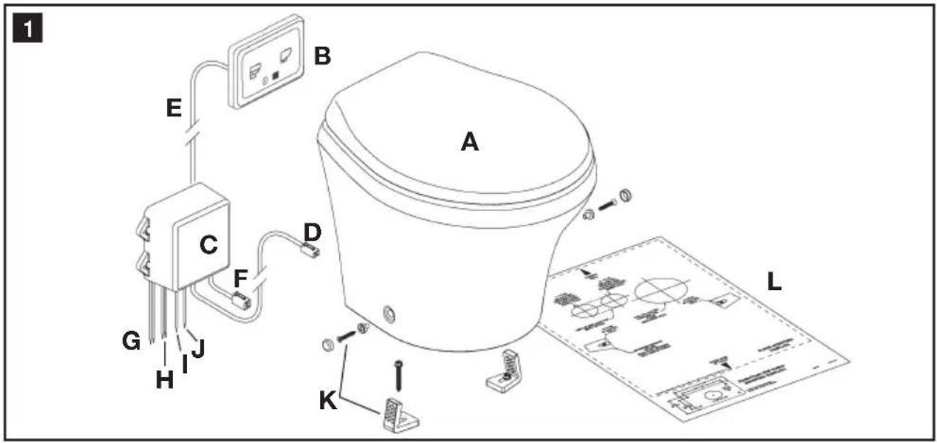
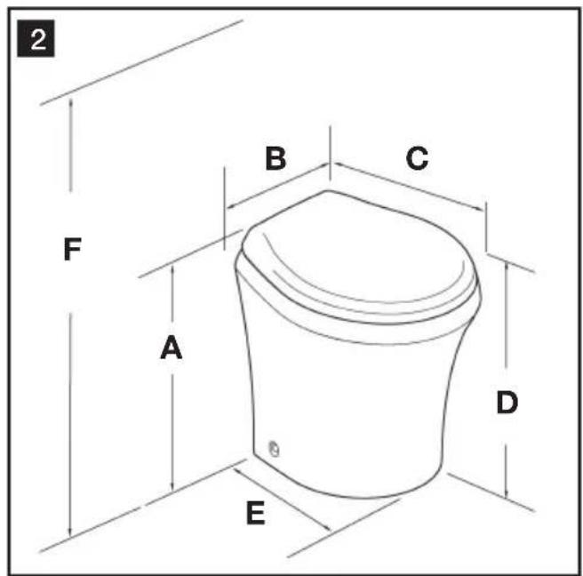
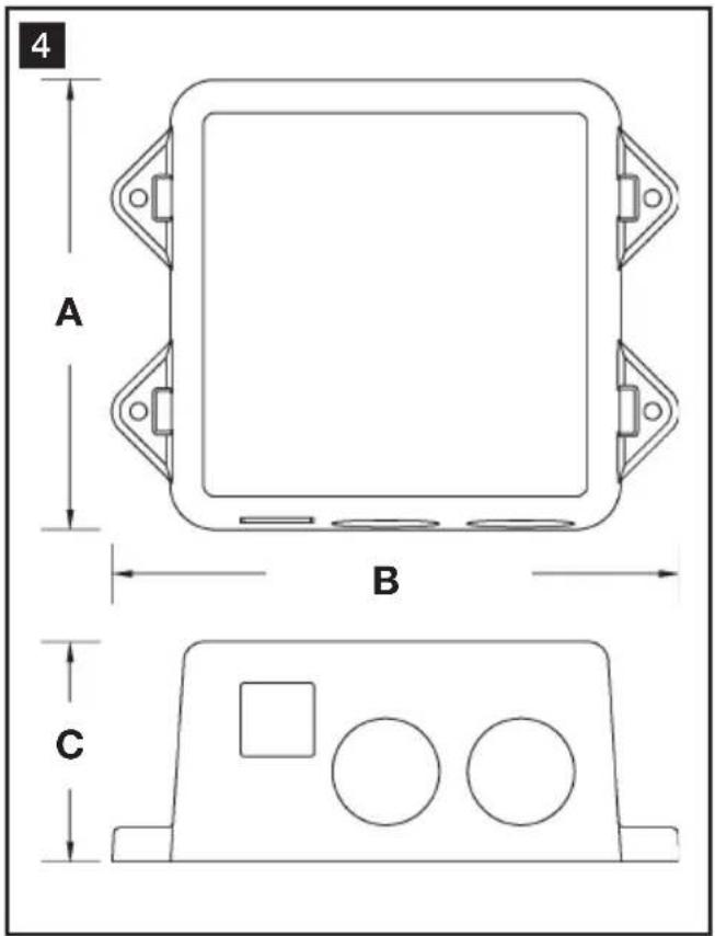
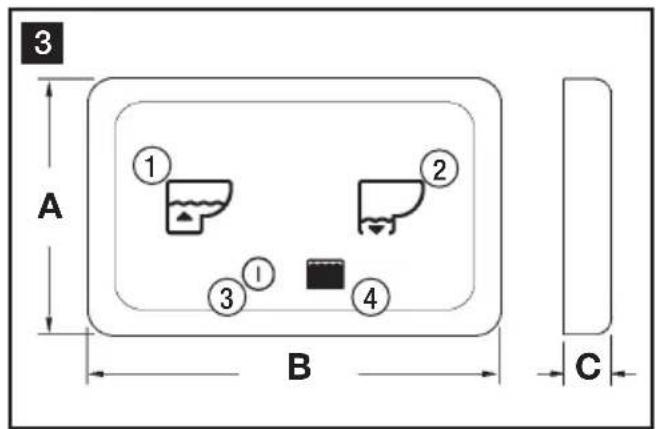
Table of contents
EN
1 Notes on using the manual 3
2 General safety instructions 3 - 4
3 Components 5
4 Specifications 6 - 7
5 Installation....8 - 11
6 Customer service....12
1 Notes on using the manual

Caution!
Safety Instruction: Failure to observe this instruction can cause material damage and impair the function of the device.

Note
Supplementary information for operating the device.
fig. 1 A, page 2: This refers to an element in an illustration. In this example, item A in figure 1 on page 2.
2 General safety instructions
The manufacturer will not be held liable for claims for damage resulting from the following:
- Faulty assembly or connection
- Damage to the unit from mechanical influences, misuse or abuse
• Alterations to the unit without express written permission from the manufacturer - Use for purposes other than those described in the operating manual
2.1 Warnings – marine applications
The following statements must be read and understood before installing, servicing and/or operating this product on a boat. Modification of this product may result in property damage.
Dometic recommends that a qualified marine technician or electrician install or service this product. Equipment damage, injury to personnel or death could result from improper installation. DOMETIC ACCEPTS NO RESPONSIBILITY OR LIABILITY FOR DAMAGE TO EQUIPMENT, OR INJURY OR DEATH TO PERSONNEL THAT MAY RESULT FROM IMPROPER INSTALLATION, SERVICE OR OPERATION OF THIS PRODUCT.

Caution! Hazard of Flooding
If the toilet is connected to ANY through-the-hull fittings, properly installed seacocks MUST be installed in all piping connected to through-the-hull fittings. Seacocks MUST be easily accessible to all users of the toilet or secondary valves fitted in hoses where they are easily accessible. All valves MUST be full bore valves and of marine quality. Screw-to-close gate valves are not recommended. Failure to do so can result in flooding which can cause loss of property and life.


Caution! Hazard of Flooding
If toilet is connected to ANY through-the-hull fittings, ALL flexible hoses must be of marine sanitation quality and must be secured to ANY fittings (such as those at seacock, vented loop or toilet) with two stainless steel, worm-drive hose band clamps at each connection. Connections MUST be checked frequently for integrity. Failure to comply can result in flooding which can cause loss of property and life.


Caution! Hazard of Flooding
If toilet rim is below the waterline at ANY time (during any conditions of heel, load or trim) and is connected to ANY through-the-hull fittings, properly positioned ventilated (vented) loops MUST be installed in intake* or discharge piping to prevent potential back siphonage of seawater into the boat. Failure to do so can result in flooding which can cause loss of property and life.
* if connected to raw water


Caution! Hazard of Flooding
If toilet uses raw water for flushing at ANY time, a raw water pump controlled by an automatically operating demand switch MUST NOT be installed. If the onboard water valve or any plumbing connections were to leak, the automatically operated pump would start and could flood the boat. Failure to comply can cause loss of property and life.


Caution! Hazard of Flooding
Before beginning any work on this product, be sure that all electrical power to the unit has been turned off and that seacocks are in the CLOSED or OFF position. Failure to do so can result in flooding which can cause loss of property and life.

Caution! Hazard of Shock or Fire
Always use recommended fuse, circuit breaker and wire size. Failure to do so can result in fire that can cause the loss of property and life.

Caution!
Overfilling the holding tank can create serious damage to the sanitation system, such as rupturing the holding tank and releasing tank contents into the bilge. To prevent this possibility, Dometic recommends using the “full” tank shut-down relay in the toilet’s electronic control module. The “full” signal from the holding tank can be generated by an optional Dometic DTM01C tank monitor or DTM04 four-level tank monitor system.
3 Components
Toilet system (fig. 1, page 2)
Ref. Description
A Macerator toilet
B Dometic DFT flush switch
C Control module
D 4-wire cable to toilet macerator pump and water valve
E Dometic DFT touchpad, DFS or DFP flush switch cable
F Cable for previous flush switch connections (discontinued models)
G Incoming electrical power wires
H Power wires to raw water pump (opt.)
I Wire for "3/4-full tank" signal
J Wire for "full tank" signal
K Floor mounting hardware kit
L Floor mounting template
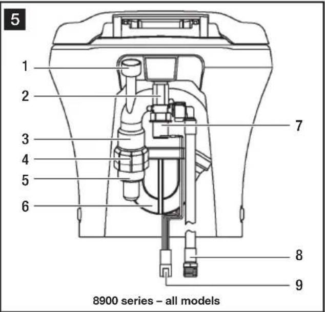
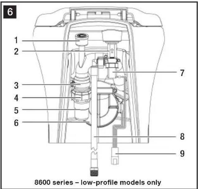
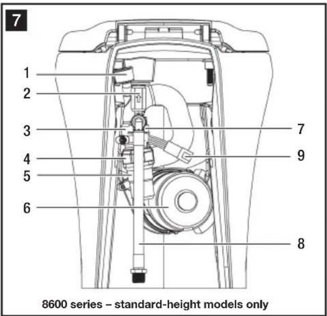
Toilets (fig. 5, 6, 7, page 5)
Ref. Description
1 Anti-siphon valve
2 Check valve
3 Discharge loop outlet
4 Discharge adapter fitting
5 Discharge hose fitting
6 Macerator pump
7 Water valve
8 Water line - 0.5 in. NPT fitting
9 4-pin cable connector
Refer to complete parts list (packed separately) for additional information.
4 Specifications
4.1 Materials
Toilet: vitreous ceramic
Macerator pump body: glass-filled polypropylene
Control module housing: ABS
Dometic DFT switch panel frame: ABS
Dometic DFT switch panel: polycarbonate resin
4.2 Minimum System Requirements
| Electrical | Circuit breaker 20 amps/12 V DC; 15 amps/24 V DC |
| Wiring 12 ga. (up to 20 ft./6.1 m from breaker) | |
| Water Supply | Fitting 0.5 in. NPT |
| Flow rate 2.0 gpm/7.6 lpm minimum | |
| Discharge | Inside diameter 1.5 in./38 mm or 1 in./25 mm |
| Horizontal run 98 ft./30 m maximum | |
| Vertical run 9.8 ft./3 m maximum |
Horizontal and vertical distances are not cumulative. Check for adequate discharge flow if installation nears one of these limits.
Specifications are subject to change without notice.
4.3 Dimensions (fig. 2, page 2)
Models 8970, 8979, 8980, 8989 (standard height)
Ref. Dimension
A 18.125 in. / 460 mm
B 14.75 in. / 375 mm
C 18.625 in. / 473 mm
D 17 in. / 432 mm - seat height
E 15.75 in. / 400 mm
F 33.5 in. / 851 mm - seat lid up
Models 8930, 8939, 8940, 8949 (low-profile height)
Ref. Dimension
A 14.75 in. / 375 mm
B 14.75 in. / 375 mm
C 18.25 in. / 464 mm
D 13.625 in. / 346 mm - seat height
E 14.875 in. / 378 mm
F 30.25 in. / 768 mm - seat lid up
Models 8670, 8679, 8680, 8689 (standard height)
Ref. Dimension
A 18 in. / 457 mm
B 14.75 in. / 375 mm
C 19.75 in. / 502 mm
D 17 in. / 432 mm - seat height
E 16 in. / 406 mm
F 33.5 in. / 851 mm - seat lid up
Dometic flush switch/status panel
(fig. 3, page 2)
Ref. Dimension
A 2 in. / 51 mm
B 3.25 in. / 83 mm
C 0.4375 in. / 11 mm
Models 8630, 8639, 8640, 8649 (low-profile height)
Ref. Dimension
A 15 in. / 381 mm
B 14.75 in. / 375 mm
C 19.75 in. / 502 mm
D 14 in. / 356 mm - seat height
E 15.375 in. / 391 mm
F 30.5 in. / 775 mm - seat lid up
Control module (fig. 4, page 2)
Ref. Dimension
A 4.25 in. / 108 mm
B 5.375 in. / 137 mm
C 2.125 in. / 54 mm
5 Installation
5.1 Fresh water system layout
Dometic macerator toilets can operate with an onboard pressurized freshwater system with a minimum flow rate of 2.0 gpm (7.6 lpm) at the toilet. Onboard fresh-water demand systems include a water pump that automatically draws water from a water storage tank when a valve
anywhere in the piping system is opened. Dometic toilets are equipped with an electrically operated water valve and an in-line check valve to prevent contamination of onboard potable supplies.

Note
Use cold water only. Include shut-off valve in water line for maintenance purposes.
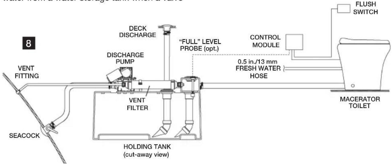
5.2 Raw water system layout
Dometic macerator toilets can flush on seawater but require a separate pump for this purpose. The pump is activated by the signal from the toilet's electronic control module that would operate the integral water valve in a fresh water system. If the raw water pump draws more than 18 amps of current, a 12 or 24 V DC electrical relay must be installed.
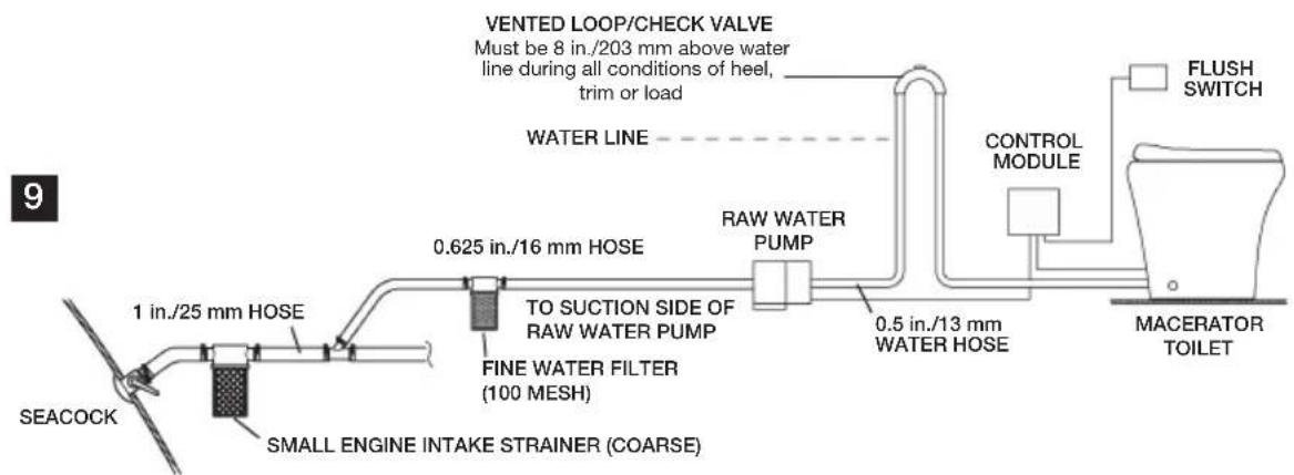

Notes
Use cold water only. Include shut-off valve in water line for maintenance purposes.
Use primary and secondary raw water filters.
Raw water pump MUST NOT be demand-type. Pump is controlled by control module.
Install vented loop as shown. It must be equipped with integral check valve that permits air into line to prevent siphoning.

Caution! Hazard of Flooding
If toilet uses raw water for flushing at ANY time, a raw water pump controlled by an automatically operating demand switch MUST NOT be installed. If the onboard water valve or any plumbing connections were to leak, the automatically operated pump would start and could flood the boat. Failure to comply with this warning can cause loss of property and life.
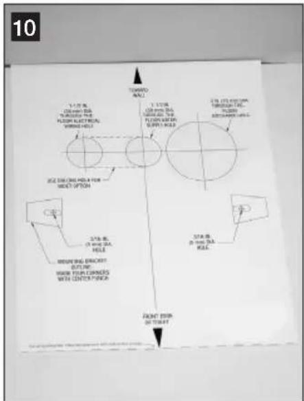
5.3 Toilet system with through-the-floor connections
- Place floor mounting template in desired location (fig. 10). For optimal user comfort, make sure walls or other interior fixtures are at least 11 in. (279 mm) away from centerline of template.
- Center punch all holes and mounting bracket corners through template.
- Remove template from floor. Drill all access and fastener holes as indicated on template. DO NOT drill mounting bracket corners.
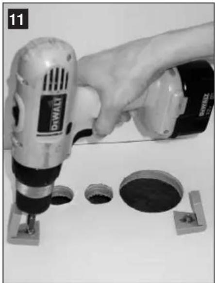
- With long hex-head screws from toilet floor bracket kit, fasten floor brackets with 3/8 in. (10 mm) socket wrench, using corner marks as guides (fig. 11).

Note
Do not completely tighten hex-head screws to floor – allow brackets to slightly slide. Brackets will tighten when fastening toilet to brackets.
- Plan flush switch panel and electronic control module locations so that electrical connections can be made with cables provided with toilet. Be sure module and wires cannot get wet.

Note
Several flush switch options are available from Dometic. Instructions for installing the Dometic flush touchpad (DFT) follow. Other available types fit either Vimar or Gewiss flush switch/status panel components. Instructions for these are included with each flush switch assembly.
-
Use Dometic DFT touchpad template to mark location of fastener and access holes. Drill 1 in. (25 mm) hole, then fasten panel bracket to wall (fig. 12).
-
Route Dometic touchpad cable (fig. 1 E, p. 2) from ethernet connector on control module to access hole at touchpad panel location. Attach cable to touchpad panel, then snap the panel cover onto the panel bracket (fig. 12).
-
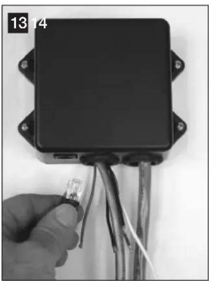
Install control module in cool, dry location and attach Dometic touchpad cable to ethernet connector on control module (fig. 13, p. 10).
-
With electrical power off, complete wiring connections to control module. Refer to wiring diagram printed with parts list (packed separately).
-
Route 4-wire control module cable (fig. 1 D, p. 2) to toilet through access hole in floor.
natural_image
Hand using a power tool to cut or install a circular component, with no visible text or symbols on the tool or background.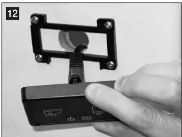
natural_image
Hand holding a small electronic device with a connector, no visible text or symbols- Route water supply and discharge plumbing to toilet according to system requirements (Section 4.2). Make sure to provide extra discharge hose length to assure easy connection to toilet (fig. 14).
- Loosen band clamp on discharge loop outlet and remove discharge adapter fitting/hose fitting assembly (fig. 15).
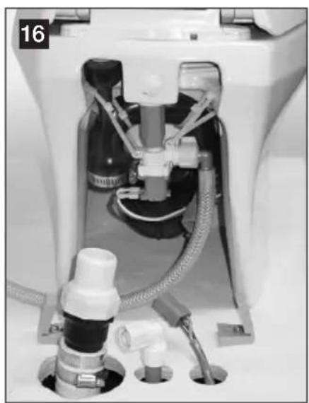
- Lubricate discharge fitting assembly and inside end of discharge hose with liquid dishwashing soap. Push discharge fitting assembly into discharge hose and connect with two hose clamps. Be sure to position hose clamp screws 180^ apart from each other (fig. 16). Place toilet near access holes and floor brackets.
- Connect toilet water line to water supply line and 4-pin connector to control module cable.
natural_image
Close-up of a black electronic device with wires and a small LED, held by a hand (no visible text or symbols)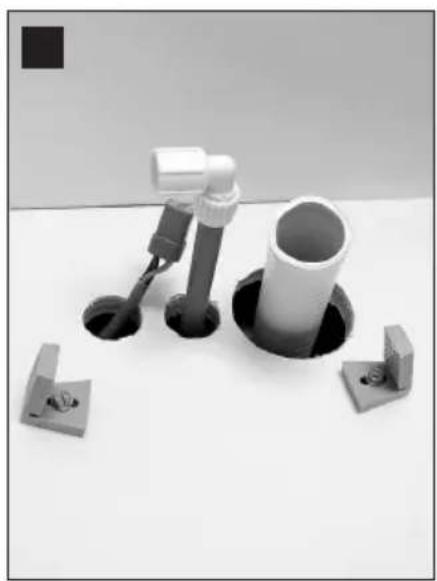
natural_image
Mechanical assembly with cylindrical components and mounting holes (no text or symbols visible)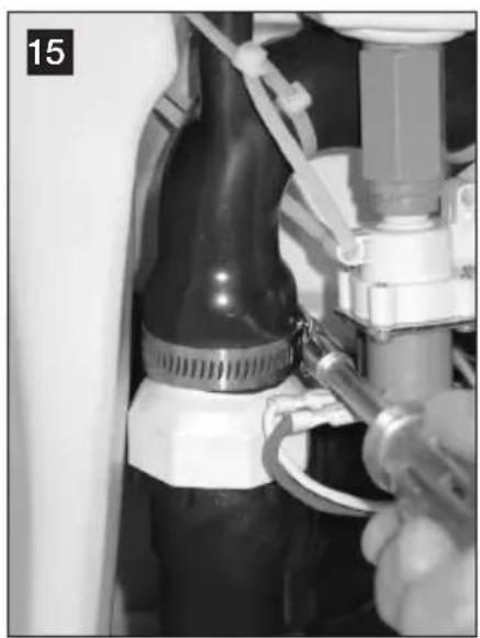
natural_image
Close-up of a mechanical assembly with a tool inserted, no visible text or symbols- Position toilet over floor brackets and tilt toilet up from back. Push discharge assembly fitting and hose up into discharge loop outlet, and tighten band clamp (fig. 17).
- Lower toilet down so that floor brackets show through fastener holes (fig. 18).
- Turn on water supply and electrical power to toilet, and check for leaks. Press "Flush" switch (fig. 3 2, page 2). If leak occurs, tighten connection.
- Insert plastic adapters from Floor Bracket Kit into fastener holes. Fasten toilet to brackets with short screws provided in kit.
- Cover floor bracket screws with plastic covers (fig. 19).
natural_image
Close-up of a medical or laboratory equipment component with tubing and connectors (no visible text or symbols)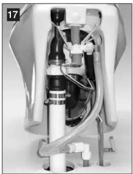
natural_image
Interior view of a medical or laboratory device with tubing and tubing, no visible text or symbols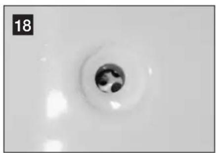
natural_image
Close-up of a circular object with a dark central feature, possibly a hole or sink, on a plain white surface (no text or symbols visible)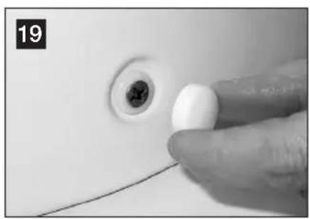
natural_image
Close-up of a finger pointing at a small white object on a white surface, with no visible text or symbols.5.4 Toilet system with through-the-wall connections
-
To route wiring and plumbing connections through the wall, use floor template to locate the vertical centerline of each hole.
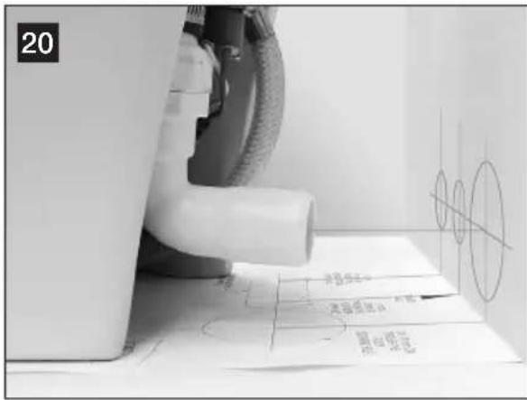
-
Place toilet in proper position and mark horizontal centerlines (fig. 20).
-
Drill holes sizes as indicated on template.
-
Route wiring and plumbing through holes according to system requirements (Section 4.2). Make sure to provide extra discharge hose length to assure easy connection to toilet.
-
Follow toilet installation instructions beginning at Section 5.3, step 12.
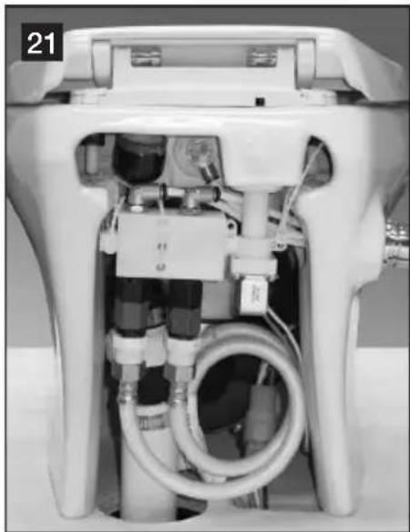
- In Section 5.3, step 3, cut out oblong access hole as marked on floor template to accommodate two water line connections and wiring.
- Route cold water supply line to toilet/bidet mixer valve water line (with blue band) (fig. 21).
- Route hot water supply line to bidet faucet hot water line (with red band).
- Route wiring and discharge plumbing through holes according to system requirements (Section 4.2). Make sure to provide extra discharge hose length to assure easy connection to toilet.
- Follow toilet installation instructions beginning at Section 5.3, step 12.
natural_image
Interior view of a white appliance with internal tubing and connectors (no visible text or symbols)6 Customer service
There is a strong, worldwide network to assist in servicing and maintaining your toilet system. For the Authorized Service Center near you, please call from 8:00 a.m. to 5:00 p.m. (ET) Monday through Friday.
You may also contact or have your local dealer contact the Parts Distributor nearest you for quick response to your replacement parts needs. They carry a complete inventory for the Dometic product line.
Telephone: 1 800-321-9886 U.S.A. and Canada
330-439-5550
International
Fax: 330-496-3097 U.S.A. and Canada
330-439-5567
International
Web site: http://www.Dometic.com

DOMETIC
Dometic Corporation, Sanitation Division
13128 State Rt. 226, P.O. Box 38
Big Prairie, OH 44611 USA
1-800-321-9886 • Fax: 330-496-3097
www.Dometic.com