
NetMax N8000 - Uncategorized ELECTRO-VOICE - Free user manual and instructions
Find the device manual for free NetMax N8000 ELECTRO-VOICE in PDF.


| Type of product | Digital audio processor and network controller |
| Brand | Electro-Voice |
| Model | NetMax N8000 |
| Dimensions (W x H x D) | 19" x 1.75" (1U) x 12" (483 x 44 x 305 mm) |
| Weight | Approximately 8 kg (17.6 lbs) |
| Power supply | 100-240 V AC, 50/60 Hz, 150W max |
| Analog inputs | 8 balanced XLR, 24-bit ADC |
| Analog outputs | 8 balanced XLR, 24-bit DAC |
| Digital audio network | Dante audio networking with redundant ports |
| DSP processing | 32-bit floating point, FIR filters, crossover, EQ, delay, dynamics |
| Control interfaces | Ethernet, USB, RS-232 |
| Software | IRIS-Net for configuration and control |
| Operating temperature | 0°C to 40°C (32°F to 104°F) |
| Storage temperature | -20°C to 60°C (-4°F to 140°F) |
| Humidity | 0% to 90% non-condensing |
| Cooling | Internal fan, side-to-side airflow |
| Mounting | 19" rack mount, 1U height |
| Cleaning | Use dry cloth; avoid solvents or abrasives |
| Safety | Disconnect power before servicing; use grounded outlets |
| Spare parts | Contact authorized Electro-Voice service centers for replacement parts |
| Repairability | Repairs should be carried out by qualified personnel only |
Frequently Asked Questions - NetMax N8000 ELECTRO-VOICE
User questions about NetMax N8000 ELECTRO-VOICE
0 question about this device. Answer the ones you know or ask your own.
Ask a new question about this device
Download the instructions for your Uncategorized in PDF format for free! Find your manual NetMax N8000 - ELECTRO-VOICE and take your electronic device back in hand. On this page are published all the documents necessary for the use of your device. NetMax N8000 by ELECTRO-VOICE.
USER MANUAL NetMax N8000 ELECTRO-VOICE
Description of the system 5
N8000 features 6
Unpacking and warranty 7
Installation instruction 8
IRIS-Net 8
Browser Interface 9
Control Elements and Connections .....10
Front Faceplate 10
SIGNAL / PEAK-LEDs 10
NETWORK-LEDs....10
SYSTEM STATUS-LEDs 11
POWER-LED 11
USB Interface....11
Rear Panel 12
AUDIO SLOTS 12
Network Module Slot 12
ETHERNET Interface....13
RS-232 Interfaces 13
REMOTE CAN BUS....13
CONTROL PORT 14
Mains Connector and Power Switch....14
Preparations 15
Mounting 15
Installation of expansion cards 15
System expansion with analog/digital inputs or outputs. 16
System expansion with a network module 16
Expansion of the DSP performance of the system....16
Interface description 17
Ethernet Interface....17
CAN Interface....18
USB connection 20
RS-232 Interface 20
CONTROL PORT 21
Audio Interfaces 23
Network configuration 25
Introduction 25
Configuration 27
Configuration and testing of an Ethernet connection with N8000. 27
Appendix 31
Application Example 31
Installation in a multi-purpose hall 31
Troubleshootings 32
Ethernet principles 33
IP addresses 34
Subnet mask 34
Automatic/Manual Allocation of IP Addresses 35
CAN-Bus Principles 36
System Examples....38
Performance Specifications 39
IP Address Table 40
IMPORTANT SAFETY INSTRUCTIONS
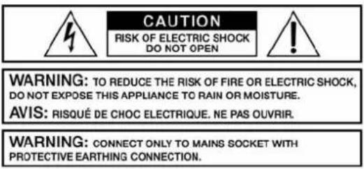

The lightning flash with arrowhead symbol, within an equilateral triangle is intended to alert the user to the presence of uninsulated "dangerous voltage" within the product's enclosure that may be of sufficient magnitude to constitute a risk of electric shock to persons.
The exclamation point within an equilateral triangle is intended to alert the user to the presence of important operating and maintenance (servicing) instructions in the literature accompanying the appliance.
- Read these instructions.
- Keep these instructions.
- Heed all warnings.
- Follow all instructions.
- Do not use this apparatus near water.
- Clean only with a dry cloth
- Do not block any ventilation openings. Install in accordance with the manufacture's instructions.
- Do not install near heat sources such as radiators, heat registers, stoves, or other apparatus (including amplifiers) that produce heat.
- Do not defeat the safety purpose of the polarized or the grounding-type plug. A polarized plug has two blades with one wider than the other. A grounding type plug has two blades and a third grounding prong. The wide blade or the third prong are provided for your safety. If the provided plug does not fit into your outlet, consult an electrician for replacement of the obsolete outlet.
- Protect the power cord from being walked on or pinched particularly at plugs, convenience receptacles, and the point where they exit from the apparatus.
-
Only use attachments/accessories specified by the manufacturer.
-
Use only with the cart, tripod, bracket, or table specified by the manufacturer, or sold with the apparatus. When a cart is used, use caution when moving the cart/apparatus combination to avoid injury from tip-over.

-
Unplug this apparatus during lightning storms or when unused for a long period of time.
-
Refer all servicing to qualified service personnel. Servicing is required when the apparatus has been damaged in any way, such as power-supply cord or plug is damaged, liquid has been spilled or objects have fallen into the apparatus, the apparatus has been exposed to rain or moisture, does not operate normally, or has been dropped.
-
Do not expose this equipment to dripping or splashing and ensure that no objects filled with liquids, such as vases, are placed on the equipment.
-
To completely disconnect this equipment from the AC Mains, disconnect the power supply cord plug from the AC receptacle.
-
The mains plug of the power supply cord shall remain readily operable.
Management of WEEE (waste electrical and electronic equipment) (applicable in Member States of the European Union and other European countries with individual national policies on the management of WEEE) The symbol on the product or on its packaging indicates that this product may not be treated as regular household waste, but has to be disposed through returning it at a Telex dealer.
IMPORTANT SERVICE INSTRUCTIONS
CAUTION: These servicing instructions are for use by qualified personnel only. To reduce the risk of electric shock, do not perform any servicing other than that contained in the Operating Instructions unless you are qualified to do so. Refer all servicing to qualified service personnel.
- Security regulations as stated in the EN 60065 (VDE 0860 / IEC 65) and the CSA E65 - 94 have to be obeyed when servicing the appliance.
- Use of a mains separator transformer is mandatory during maintenance while the appliance is opened, needs to be operated and is connected to the mains.
- Switch off the power before retrofitting any extensions, changing the mains voltage or the output voltage.
- The minimum distance between parts carrying mains voltage and any accessible metal piece (metal enclosure), respectively between the mains poles has to be 3 mm and needs to be minded at all times. The minimum distance between parts carrying mains voltage and any switches or breakers that are not connected to the mains (secondary parts) has to be 6 mm and needs to be minded at all times.
- Replacing special components that are marked in the circuit diagram using the security symbol (Note) is only permissible when using original parts.
- Altering the circuitry without prior consent or advice is not legitimate.
- Any work security regulations that are applicable at the locations where the appliance is being serviced have to be strictly obeyed. This applies also to any regulations about the work place itself.
- All instructions concerning the handling of MOS-circuits have to be observed.
NOTE: SAFETY COMPONENT (MUST BE REPLACED BY ORIGINAL PART)

HF-Interference
This equipment has been tested and found to comply with the limits for a Class B digital device, pursuant to Part 15 of the FCC Rules. These limits are designed to provide reasonable protection against harmful interference in a residential installation. This equipment generates, uses and can radiate radio frequency energy and, if not installed and used in accordance with the instructions, may cause harmful interference to radio communications. However, there is no guarantee that interference will not occur in a particular installation. If this equipment does cause harmful interference to radio or television reception, which can be determined by turning the equipment off and on, the user is encouraged to try to correct the interference by one or more of the following measures:
- Reorient or relocate the receiving antenna
- Increase the separation between the equipment and receiver
- Connect the equipment into an outlet on a circuit different from that to which the receiver is connected
- Consult the dealer or an experienced radio/TV technician for help

D ECLARATION
OF
CONFORMITY
Applicant: Telex EVI Audio GmbH
Hirschberger Ring 45
94315 Straubing
Germany
Type of Equipment: System Controller
Model Number: N8000
Serial Number: 1703230424010021
Test Report Number: 266.242
This device complies with Part 15 of the FCC Rules for Class B Devices.
Regulation: United States Code of Federal Regulations 47
Part 15-Digital Devices, Subpart B-Unintentional Radiators, Class B
Standard:
ANSI C63.4-2003 Methods of Measurement of Radio-Noise
Emissions from Low Voltage Electrical Equipment in the Range of 9 kHz to 40 GHz.
Limit:
DIN EN 55022:1999-05 Information Technology Equipment
Radio Disturbance Characteristics –
Limits and Methods of Measurement
Verified by:
Date: Straubing, May 2 ^nd , 2006
1 Introduction
First of all we want to express our thanks and offer our congratulations that you have selected the NetMax N8000 System Controller from Electro-Voice. Before operating the NetMax N8000 please read this instruction manual attentively to ensure that this device provides optimal performance and that damages due to improper use are avoided.
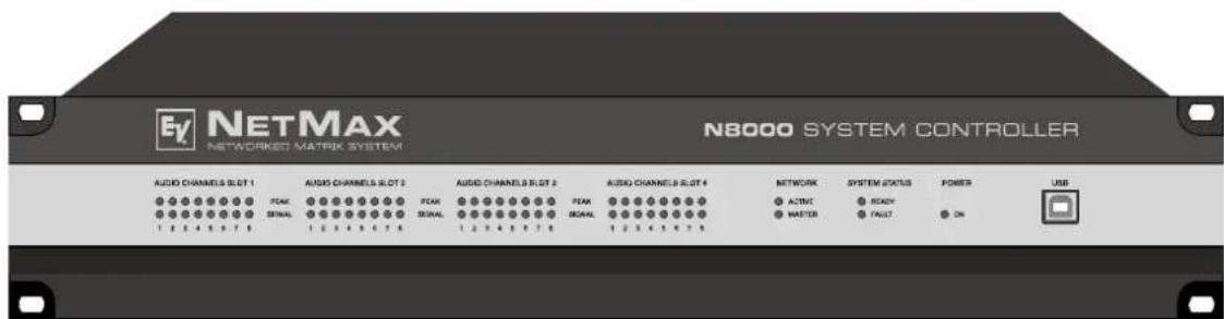
N8000 front view
1.1 Description of the system
NetMax is a modular, network-compatible and freely configurable audio system with which complete system solutions can be constructed. These system solutions exactly meet the customers' requirements. Applications are all kinds of professional audio installations, complex building sound reinforcement systems as well as concert sound applications. NetMax integrates all components ranging from the matrix to the speakers including system control and system monitoring in a common audio platform. The configuration, operation and monitoring of a NetMax system are effected by the PC Software IRIS-Net - Intelligent Remote & Integrated Supervision.
The central unit of NetMax is the N8000 system controller with up to 32 audio channels, mixer and matrix functions, signal processing and extensive control and monitoring functions. Several N8000 can be connected via a CobraNet™ audio and control network so that a large, decentralized audio system can be assembled.
NetMax also manages the Electro-Voice P-series remote amplifiers including its speaker and system monitoring functions. The connection is directly effected via CAN to the N8000.
A NetMax system meets all relevant safety requirements. All audio connections, interfaces and processor systems are monitored and displayed in case of fault. By using CobraNet™ redundant networks can be assembled.
1.2 N8000 features
NetMax N8000 is an all-purpose digital audio system controller with outstanding performance features. A high quality system design provides excellent audio quality and clear sound, which is achieved by the application of high-end 24 Bit A/D and D/A converters with 120 dB volume range, high-quality input and output circuits in the analog domain and digital signal processing with optimized 48 bit double-precision algorithms. Hence, the N8000 is even particularly suitable for demanding applications in theatres, concert halls, big churches etc.
NetMax N8000 is highly flexible due to the modular hardware design which renders many other applications possible. Four slots with 8-channel audio modules at the rear of the device offer up to 32 local audio channels. Each slot can be equipped either with an audio input module or an audio output module. So, various configurations (e.g. 8-in/8-out, 8-in/16-out, 8-in/24-out, 16-in/16-out, 24-in/8-out) can be realized in only one single device. In addition, N8000 can be equipped with a CobraNet ^™ network module. Therefore, several N8000 can be integrated in a network and be connected to a large, sophisticated system.
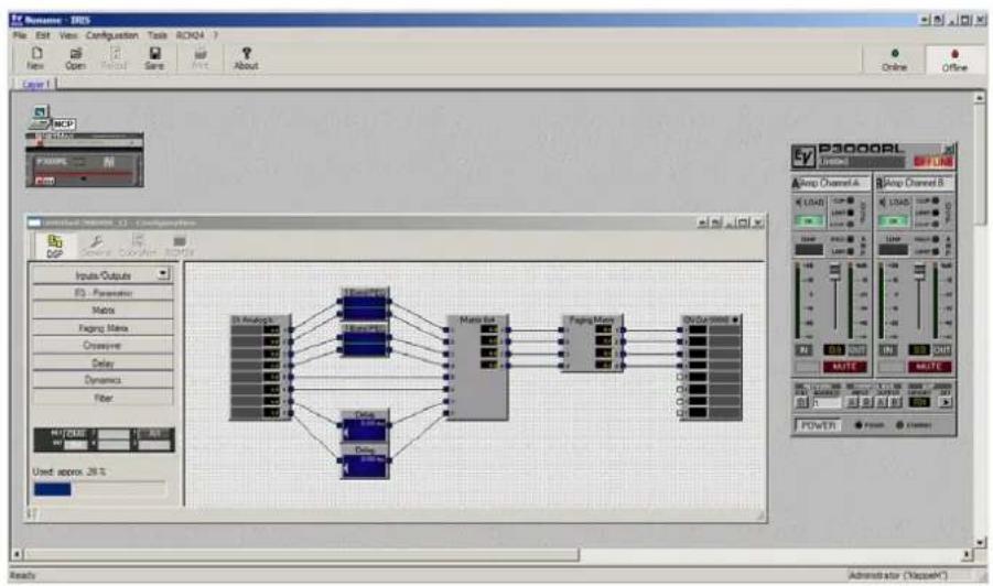
The signal processing in the N8000 is effected on powerful audio signal processors where, depending on the stage of expansion, up to 8 DSPs are available. The software contains a multitude of freely programmable signal processing components. Among other things, these are filters with all possible characteristics, parametric and graphic equalizer, crossover network, matrix router and matrix mixer, delays, dynamic functions, etc. Diverse configurations can be created by combining and connecting these DSP blocks. The programming is done via the PC software IRIS-Net. With that, you choose the desired components from a signal processing library, place them in a working area on the screen and wire them to a signal flow chart. Thus, the resulting DSP configuration has only to be transferred to the N8000 and is ready for immediately use.
The powerful signal processing allows complex configurations for the adjustment and control of the sound system, depending on the application or type of event. Thus, the sonic quality of PA speakers, monitor speakers, front fill systems as well as of the sound reinforcement of adjoining rooms, lobbies, areas for the staff etc. can be optimized and tuned individually. In other words, the N8000 copes with every application - even with large and complex systems - absolutely exactly and reliably.
In addition to the audio processing, the NetMax N8000 is equipped with diverse control functions. The scheduling with calendar function makes it possible to program one-time or recurring events. The recurrence can occur annually, monthly, weekly, daily, hourly or even within smaller time intervals. Furthermore, daily programs can be set up and can also be combined to weekly operations. With the event control, reactions to certain events or system states can be configured, e.g. in case of overstepping or undershooting of threshold values. Faults in the device or in the complete NetMax system are detected automatically and can be displayed on the PC screen or transmitted to external sites if necessary.
Faults and other events are recorded in an internal log file with date and time. Furthermore, it can be defined which types of errors or events should be recorded. The log can be read out and displayed on the screen at any time. In the NetMax N8000 individual functions can be integrated into complex operations. For example, several parameters can be set with various values or states in a scene and can be changed manually or automatically at any time.
The NetMax N8000 is equipped with all relevant interfaces by default in order to provide the connection to the network and external components. The Ethernet port makes the connection to existing building networks (intranet) and communication via the Internet possible. Ethernet is also the common connection between one or more N8000s and a PC with IRIS-Net software for the configuration, control and monitoring of a complete NetMax system. Two RS-232 serial ports can be used in order to control the N8000 from external multi-media systems, e.g. Crestron™ or AMX™. For that, an open interface protocol is available. The remote CAN-bus serves as connection to Electro-Voice remote amplifiers. Up to 100 amplifiers can be attached via CAN to one single N8000. Together with additional N8000s and amplifiers they can also be integrated in a complex and powerful audio system. The NetMax N8000 also has a control port which offers freely programmable control inputs and outputs. Switches, potentiometers or external control voltages can be connected to the control inputs (GPIs). Any logic and analog functions can be programmed. External elements which can be used to signal certain states can be attached to the control outputs (GPOs). A PC can be connected to the USB port on the front faceplate if the N8000 has been installed in a rack and the Ethernet port cannot be reached easily. Via the USB interface the network parameters of the N8000 can be edited and files containing the entire N8000 configuration can be transferred.
The highest standards regarding construction and mechanical working have been followed. The chassis is extremely robust and, therefore, effectively protects the electronics against outside influences. A temperature controlled fan provides thermal stability and also constant ambient conditions inside the device. All audio interfaces are electronically balanced and have Phoenix screw terminal connectors.
By reading this instruction manual you will get to know many additional features and functions of the NetMax N8000. Please read on attentively and keep this manual in order to be able to consult it at any time.
1.3 Unpacking and warranty
Please open the packaging and uncase the N8000. The following accessories are added to the device:
• N8000 owner's manual (this document)
- Power supply cord
• 2 CAN terminating impedances
• 2 Phoenix connectors (6-pin)
- Warranty card
Please completely fill out the warranty card in the event that you need to make a warranty claim. We also ask you to keep the sales slip and the packaging together with the warranty card in case the unit has to be returned.
1.4 Installation instruction
The N8000 has to be set up and installed so that both air supply and ventilation are ensured on both sides of the device. The direction of ventilation is from left to right when you look at the front faceplate. Devices with an opposing routing of air flow should not be installed in the same rack. When installing the N8000 in a rack, a free air duct between the sides of the N8000 and the side panel of the rack to the upper rack ventilation must be observed in order to ensure sufficient air ventilation. There must be at least 100 mm free space for ventilation above the rack.
ATTENTION:
The maximum ambient air temperature of +40°C should not be exceeded in order to ensure failure-free operation.
Standard installation rails should be used when mounting an N8000 in transport racks in order to prevent twisting of the front faceplate.
The N8000 must be protected against: dripping/splashing water, direct solar radiation, high ambient air temperature or direct impact of heat sources, high moisture, heavy vibrations and dust deposit.
If these conditions cannot be ensured permanently, maintenance is obligatory at regular intervals in order to prevent any breakdowns which are mainly due to negative environmental influences.
If the N8000 is transported from a cold to a warm environment, moisture may condense at the core. The device should not be started up before warming to the changed temperature (approx. after 1 hour). If a solid or liquid is in the housing, cut the device off from the mains power at once and have the device checked by an authorized service center before re-using it.
1.5 IRIS-Net
The IRIS-Net (Intelligent Remote & Integrated Supervision) PC software is used to configure and operate the N8000 system controller. The configuration of the N8000 can be done offline (i.e. without connection between the PC and the N8000) on the PC. After the connection between the PC and the N8000 has been established via Ethernet, the configuration can be transmitted to it. In addition to configurations, IRIS-Net can also be used for extensive supervision, control and monitoring of N8000 system controllers (and Electro-Voice Precision Series Remote Amplifiers which are connected to them).
Please see the short IRIS-Net instruction in the menu: 3. Quick Start Guide ...
1.6 Browser Interface
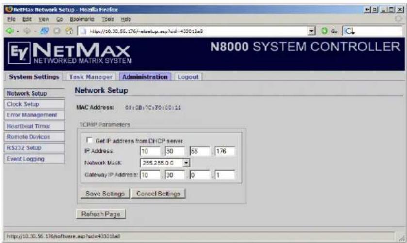
Some of the configuration and operation options of the N8000 which are available in IRIS-Net are also provided by the N8000 browser interface. Any standard Internet browser with activated JavaScript and CSS can be utilized in order to use the browser interface. Please find the detailed information on the N8000 browser interface in the file N8000 browser manual in the IRIS-Net setup directory (\Documentation\NetMax).
flowchart
graph TD
    A["Input Outputs"] --> B["Data"]
    A --> C["Data"]
    A --> D["Data"]
    B --> E["Processing Unit"]
    C --> E
    D --> E
    E --> F["Output Channel 1"]
    E --> G["Output Channel 2"]
    E --> H["Output Channel 3"]
IRIS-Net (Intelligent Remote & Integrated Supervision)
N8000 Browser Interface
2 Control Elements and Connections
2.1 Front Faceplate
The front faceplate of the N8000 has level and status displays and it offers also the possibility to connect a PC via a USB interface. SIGNAL / PEAK-LEDs exist for all 32 audio channels. The channels are combined to groups of 8 and assigned to the audio-slots 1 to 4 at the rear. Additional LEDs inform about the states of the network, system and device and give a quick overview of whether the system is working faultlessly or if a problem has occurred.

SIGNAL / PEAK-LEDs
AUDIO CHANNELS SLOT 1
PEAK SIGNAL
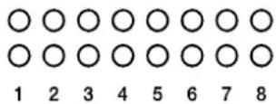
These LEDs serve as level meter display for input and output signals. The SIGNAL-LED begins to flash at -25 dBU and indicates if a signal generally exists at the input or at the output. The PEAK-LED flashes when the N8000 is operated close to the level meter's limit. The limit is approx. at +18 dBU. The maximum level meters is +21 dBu so that
there is 3 dB of head room until the final clip limit is reached. The PEAK-LEDs should only flare up sporadically in case of dynamic peaks. If the PEAK-LED of an input flashes constantly or very often, you should reduce the corresponding input signal slightly. If the PEAK-LED of an output flashes constantly, the internal gain should be reduced or else the connected device will be permanently overdriven.
NETWORK-LEDs
NETWORK
○ ACTIVE
○ MASTER
If the N8000 is operated on an audio network, e.g. CobraNet™, these LEDs show the status of the network. The ACTIVE-LED flashes or twinkles when audio data is sent or received via the network. If the LED is off, no communication via the audio network is taking place. The
MASTER-LED is on when the N8000 serves as clock-master - in case of CobraNet™ it is also named the conductor. There is always only one master in an audio network, i.e. the MASTER-LED will only be illuminated on one N8000 within the network. If the unit currently functioning as
clock master breaks down or is removed from the network, another N8000 will take over this function automatically.
SYSTEM STATUS-LEDs
SYSTEM STATUS
○ READY
○ FAULT
These LEDs indicate device or system states. The READY-LED is on when the device has booted after switch-on and when it is ready for operation. An illuminated FAULT-LED indicates an internal error in the N8000 or an error in the NetMax system. During the configuration of the N8000, it
can be specified which errors should be displayed. If the FAULT display is on, the error should be identified promptly. This can be done using the detailed diagnostics within the IRIS-Net PC software. The source of the fault has to be remedied immediately.
POWER-LED
POWER
ON
This LED is permanently green when the N8000 is powered on. If the ON indication is not illuminated, even though the device is switched on, this device may not be connected to the power supply system or the primary fuse may be faulty.
USB Interface
USB
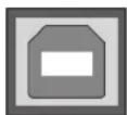
A PC can be connected at the front panel via the USB interface. Thus, it is possible to connect the N8000 with a PC even it is already installed - i.e. when the Ethernet interface at the rear panel is perhaps no longer accessible. Via the USB interface the network parameters of the N8000 can be edited and files containing the entire N8000
configuration can be transferred. You can find the necessary USB driver in the subdirectory \Driver\USB in the IRIS-Net setup directory. Please see chapter Interface description for more information on technical details concerning the USB interface and the other interfaces of the N8000 which are described in the following section.
2.2 Rear Panel
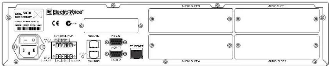
There are all connections for analog and digital audio signals, control interfaces and the power supply at the rear panel of the N8000.
AUDIO SLOTs
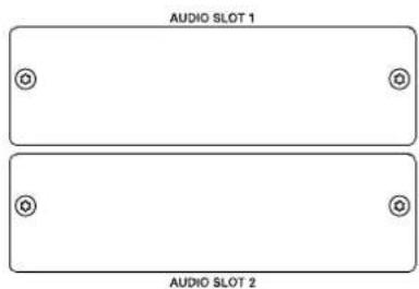
The AUDIO SLOTS 1 - 4 are module slots for the installation of NetMax audio modules. There are both analog and digital input and output modules available. Also, a module for microphone input sensitivity is optionally available. Each slot can accept any module so you can equip those inputs and outputs which you need for your specific application. The N8000 detects the type of the module automatically and offers the corresponding configuration possibilities.
ATTENTION:
The N8000 has to be switched off if you want to change or install a module. You will find detailed instructions in the data sheet of the corresponding module.
Network Module Slot
natural_image
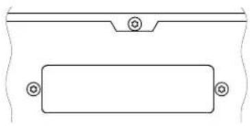
Pure technical line drawing of a rectangular component with mounting holes (no text or symbols)This slot is provided for the installation of a network module, e.g. CM-1 CobraNet™ module. There are all 64 audio channels - 32 inputs and 32 outputs - internally available at this slot. The CM-1 allows up to 32 digital audio input signals and 32 digital audio output signals to be transmitted via a CobraNet™ network simultaneously. Thus, several N8000
NetMax system controllers can be connected to create a large, distributed audio system. The
N8000 automatically detects an installed network module. The module can be configured in the PC software IRIS-Net.
ATTENTION:
The N8000 has to be switched off if you want to change or install a module. You will find detailed instructions in the data sheet of the corresponding module.
ETHERNET Interface
ETHERNET
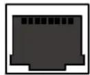
A computer and/or other N8000 devices can be connected via the Ethernet interface for 100Base-TX / 10Base-T Ethernet networks. Normally this connection is established via a standard (straight through) Ethernet cable and an Ethernet hub or a switch. If the N8000 is to be connected
directly with a computer or another N8000, a crossed Ethernet cable (crossover cable) must be used.
RS-232 Interfaces
RS-232
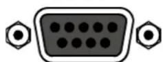
PORT 1
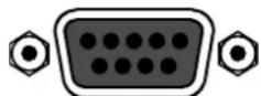
PORT 2
The N8000 can be connected to external devices, such as multimedia system (AMX ^TM , Crestron ^TM ) or facility management systems via the two RS-232 interfaces. All N8000 functions and parameters can be controlled and monitored via RS-232. Communication is done using an ASCII parser which is easy to implement. Thus, a NetMax system can be easily combined with media and touch panel control systems. A PC can also be connected to the RS-232 port to access N8000 parameters using a terminal program
like Hyperterminal. A special instruction set is available in order to establish a connection to a PROMATRIX/PROANNOUNCE system. The two RS-232 ports can be configured according to their corresponding application via the IRIS-Net PC software.
REMOTE CAN BUS
REMOTE
CAN BUS
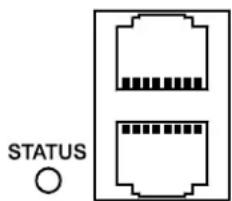
Electro-Voice remote amplifiers and other devices with CAN interfaces can be connected to the N8000 via the CAN interface. Up to 100 remote amplifiers can be connected with a single N8000. All connected components are linked to the NetMax monitoring and control platform.
The STATUS-LED is provided to monitor the communication on the CAN bus. If the CAN interface is not in use, the LED is deactivated. In normal mode the LED flashes every 2
seconds. The duration of the flashing within these 2 seconds depends on the bus load. The higher the bus load is the longer the duration of the flashing within these two seconds will be.
CONTROL PORT
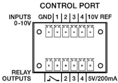
The CONTROL PORT contains four freely programmable control inputs, three freely programmable control outputs, one ready/fault output as well as reference connections for ground, +5 V and +10 V.
The control inputs IN1 - IN4 are DC inputs, which internally are connected to ground via pull-down resistors. From external sources voltages between 0 V and +10 V are possible. Either switch-mode functions or variable functions can be programmed for the control input via the IRIS-Net PC
software. Examples of use are: power on/standby switching, preset switching or parameter control.
The control outputs OUT2 - OUT4 are relay contacts, which are open circuits in off-state (off). When the output is in on-state (on) the outputs are connected to ground. The outputs are able to signal internal states and they can directly operate LEDs, indicator lights or relays. The +5 V reference voltage is able to energize the externally connected elements with up to 200 mA. Operating states (critical temperature, overstepping or falling below of defined limit values, faults, etc.) can be relayed to central operation stations or other systems (fire alarm systems, life safety systems) even without use of a PC via the control outputs. You will find detailed information regarding configuration of the control ports in the IRIS-Net documentation.
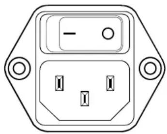
Mains Connector and Power Switch
natural_image
Front view of an electrical outlet with three slots and a minus symbol (no text or labels)Please use the enclosed power cable in order to connect NetMax N8000 to the mains power supply. The N8000 is compatible with a supply voltage between 100 V AC and 240 V AC. Therefore, a supply voltage switch is not necessary. Internally, there is a mains fuse which is normally only blown in case of a fault. The fuse should only be replaced with an equivalent fuse with identical values for current, voltage and actuating characteristics by an authorized service center.
The N8000 can be switched on and off with the power switch on the rear of the device. The ON-LED on the front panel is immediately illuminated after switch-on. The N8000 boots and initializes all parameters with those values that had been previously active. The initialization takes some seconds. As soon as N8000 is ready for operation, the READY-LED is also illuminated.
3 Preparations
3.1 Mounting
1. Install the expansion cards.
If you have purchased expansion cards (AI-1, AO-1, CM-1, DSP-1, etc.) for your N8000 system controller, please install them. In this regard, please note the paragraph page 15 as well as the installation instructions in the manuals which are enclosed to the expansion cards.
2. Connect the power cable.
Please pay attention that the power switch of the N8000 (above the mains connector) is off.
3. Install the program IRIS-Net (Intelligent Remote & Integrated Supervision) on your PC.
Please see the installation instruction for IRIS-Net in the file iris_readme.htm.
4. If you have installed expansion cards with inputs or outputs (AI-1, AO-1 or CM-1) in step 1, connect the corresponding devices now.
Please note the instruction manual both of the expansion cards and the used devices.
5. Connect the Ethernet interface of the N8000 with the PC via an appropriate Ethernet cable.
Please see the corresponding chapter Ethernet Interface on page 17.
6. If your application also utilizes Electro Voice P-series Remote Control amplifiers, connect the CAN interface of the N8000 with the amplifiers.
Please see the corresponding chapter CAN Interface on page 18.
7. Switch on the N8000 (via the power switch at the rear), the computer and any additional connected devices, if used.
In order to avoid any pops or thumps that may damage your speakers, please switch on the connected devices (if used) in the following order: audio signal sources - mixer and/or recorders - (power) amplifiers. These devices should be switched off in the reverse order.
8. Now start the IRIS-Net program on your PC.
You will find a program introduction in the online help of IRIS-Net and the corresponding quick start guide in the menu: ▷. Quick Start Guide ...
3.2 Installation of expansion cards
The options for expanding the N8000 controller through the use of expansion cards are explained in this chapter. The N8000 can be equipped with expansion cards in different ways:
- 4 Slots (module slots) for the expansion of the system with analog/digital inputs (AI-1, MI-1, DI-1) or outputs (AO-1)
- 1 network module slot for the installation of a network module, e.g. CM-1 CobraNet™ Module
- 1 DSP expansion module (DSP-1) for the expansion of the storage capacity and signal processing
ATTENTION:
It is essential to switch off the N8000 if you want to install or change a module. You will find detailed instructions in the data sheet of the corresponding module.
System expansion with analog/digital inputs or outputs
There are four slots at the rear of the N8000 which are intended to expand the systems with analogue or digital inputs or outputs. These slots have the marking AUDIO SLOT 1 to AUDIO SLOT 4 (see the figure on page 12). Any combination of the following types of expansion cards can be installed:
• AI-1 with 8 analog inputs
• MI-1 with 8 microphone inputs
• DI-1 with 8 digital inputs
• AO-1 with 8 analog outputs
You can choose any slot for the installation of the expansion cards as the slot is automatically detected by the N8000 after the installation.
System expansion with a network module
An audio network interface for CobraNet ^™ can be installed in the network module slot on the rear panel of the N8000. The CM-1 module that is used for this purpose has two Ethernet connections (Primary and Secondary) so a redundant network can be established. Up to 32 digital audio input signals and 32 digital audio output signals can be transmitted simultaneously.
Expansion of the DSP performance of the system
The N8000 system controller has efficient DSP modules with a total computing power of 300 MIPS and a working memory for a maximum delay of 21.8 seconds. If this does not meet the requirements of your application, the processing power as well as the working memory of the N8000 can be increased by installing the DSP-1 NetMax DSP expansion module. This allows the execution of more complex DSP programs and the use of longer delay times or additional delay lines.
3.3 Interface description
Ethernet Interface
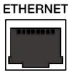
By connecting the N8000 system controller via the Ethernet interface, the communication between the N8000 and one or several PC is possible. This allows the configuration of N8000 via IRIS-Net software. Furthermore, the whole connected system (consisting of N8000s and EV Precision Series Remote Control Amplifiers) can be operated and monitored. By using appropriate network hardware it is even possible to operate the N8000 via a wireless network (WLAN). The Ethernet interface on the rear of N8000 is a RJ-45 connector (8P8C). Both 10Base-T and 100Base-TX Ethernet standards are supported. The connections of the Ethernet interfaces can be seen in the following figure and table.
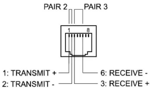
Pin Assignment of Ethernet jack
| Pin | Name | Description Pair | ColourT568A T568B | ||
| 1 | Tx+ | Transmit+ | 2 | Green striped Orange striped | |
| 2 | Tx- | Transmit- Green Orange | |||
| 3 | Rx+ | Receive+ | 3 | Orange striped Green striped | |
| 6 | Rx- | Receive- Orange Green | |||
The pin assignment of the Ethernet connector is shown in the following figure. The connector is viewed from the contact side.
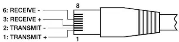
Pin Assignment of Ethernet plug
The maximum length of a connected cable segment is 100 meters in both Ethernet standards, in which two twisted pairs are used in one cable. Category 3 (unshielded CAT-3) can be used for 10Base-T communication. Category 5 (CAT-5) must be used for 100Base-TX. Cat-5 cable is compatible with 10Base-T as well.
If the N8000 is connected via a patch cable to a hub/switch, the wiring of the cable at pin 1 of the first connector has to be connected with Pin 1 of the other connector; this is the same regarding the other pins as well. There are the T568A and T568B standards for the colors of the different wires used. However, T568B standard is more widely-used.
If a crossover cable is used in order to connect a N8000 with a PC directly, pair 2 has to be interchanged with pair 3 on one side of the crossover cable. Thus, the necessary swap of the sending and receiving lines that is internally processed in a hub/switch takes place.
CAN Interface
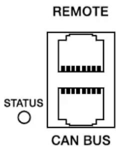
The network for the Electro-Voice remote power amplifiers is based on the CAN-bus standard, which has become widely accepted in the automotive, industrial and security sector and which has proved itself for years. The CAN-bus is a balanced serial interface to transmit commands and data. 100 power amplifiers or other devices up to a maximum cable length of 1000 meters can be connected per CAN-bus.
Each bus member has 2 RJ-45 connectors for the remote CAN-bus. The connectors are connected in parallel and serve as input or output (for a
loop-through) of the remote network. The CAN-bus has to be terminated with a 120 Ω terminating resistance at both ends. Therefore, two terminating connectors CAN-TERM 120 Ω are included with the N8000. Please plug these terminating connectors in the free RJ-45 connectors of the first and the last device at the CAN-bus.
In addition to the CAN-bus, a balanced audio monitor signal is carried in the network wiring in order to monitor the input and output signals of all remote networks. This monitor bus makes it possible to monitor the input and output signals of all power amplifiers existing in the remote network via the software without the need for additional wiring work. At the N8000, the monitor bus can be gripped at a CAN connector (pins 7 and 8), it can be connected with an audio input and routed to a monitor box (e.g.) for monitoring purposes.
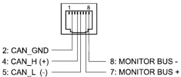
Pin Assignment of CAN jack
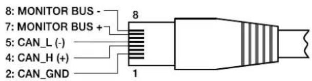
Assignment of CAN plug
| Pin | Name | ColourT568A T568B | |
| 2 | CAN_GND Green Orange | Orange | |
| 4 | C A N _ H ( + | ||
| 5 | CAN_L (-) Blue striped | ||
| 7 | MONITOR BUS + Brown striped | ||
| 8 | MONITOR BUS - Brown | ||
B I u
The CAN-bus makes it possible to use different data transmission rates, in which the boud rate is indirectly proportional to the length of the bus. If the network is only slightly extended, higher baud rates up to 500 kbit/s are possible. In case of larger extensions, the baud rate has to be lowered (to a min. transmission rate of 10 kbit/s). The following table explains the relationship between baud rate and length of the bus or extension of the network. In principle, bus lengths over 1000 meters should only be realized with repeaters.
| Transfer rate (in kbit/s) | Bus length (in m) |
| 500 | 100 |
| 250 | 250 |
| 125 | 500 |
| 62,5 | 1000 |
| 20 | 2500 |
| 10 | 5000 |
Please see the CAN bus principles chapter on page 36 in the appendix of this document as well as the instruction manuals of the connected devices for further information on CAN bus (especially on system examples and performance specifications).
USB connection
USB

The USB interface on the front panel of the N8000 uses the USB 1.1 standard. Accordingly, the low speed (1,5 MBit/s) and full speed (12 MBit/s) transfer rates are supported. According to USB specifications, the cable which is connected to this interface must not be longer than 5 meters. The USB interface of the N8000 is a USB-B (female) connector.
The standard pin configuration can be seen in the following figure and table.
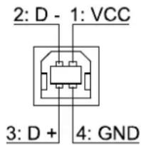
Pin Assignment of USB jack
| Pin Name | Description | |
| 1 | V | C |
| 2 D- Data - | ||
| 3 D+ Data + | ||
| 4 GND Ground | ||
C
+
5
RS-232 Interface
RS-232
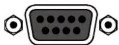
PORT 1
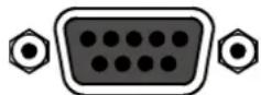
PORT 2
With the RS-232 interface on the rear panel, communication with the N8000 is possible via a simple ASCII communication protocol. Thus, the N8000 can be operated and configured via external devices (examples are, among other things, media control systems and PROMATRIX/PROANNOUNCE DPM4000). In order to make data transfer between the N8000 and the connected device possible, the interfaces on both sides of the transmission route must be identically configured. The configuration of the interface of the N8000 is given in the following table.
| Parameter Value | |
| Data bit 8 | |
| Parity bit - | |
| Stop bit 1 | |
| Transfer rate | 19200 bit/s |
The pins of the RS-232 interface used in the N8000 are indicated in the following illustration and table. Connections which are not given are internally connected in the N8000 so that the communication between the N8000 and the connected device is possible via a software handshake system. The cable which is used for the connection should not be longer than 15 meters.
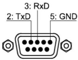
Assignment of RS-232 jack
| Pin | Name | Description | Input/Output (view from N8000) |
| 2 | TxD Transmit Out | ||
| 3 | RxD Receive In | ||
| 5 | GND Signal Ground - |
CONTROL PORT
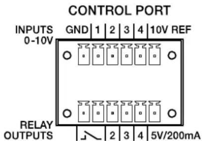
The control port on the rear of N8000 is divided into two parts. Two Phoenix connectors (6-pin) are included in delivery in order to be able to connect external components.
Control Inputs
The upper part, which is marked as INPUTS 0-10V on the device, provides four freely programmable control inputs for voltages between 0 volt and 10 volts. The inputs are numbered in order from 1 to 4. The N8000 provides its own voltage supply for externally connected monitoring elements, e.g. potentiometers or switches. The voltage supply is available at the 10V REF and GND connectors of the control port.
ATTENTION:
The maximum allowable current at the 10 V REF is 100 mA.
The following figure shows an example application for the "analogue circuit" on the control inputs of the N8000. A voltage which can be changed via a potentiometer is connected at the control input 1. The N8000 can be configured via IRIS-Net so that this voltage can be used to adjust a variable parameter, for example, adjusting the volume of an audio input or output.
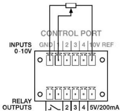
Control port with potentiometer
An example for a "digital circuit" on a control input of N8000 is shown in the following figure. The control input 2 is connected to ground via a switch (normally open contact). In IRIS-Net the N8000 can be so configured that, for example, an audio input or output channel can be muted by operating a switch. The threshold voltage for high/low which are used for this purpose are freely configurable for any input.
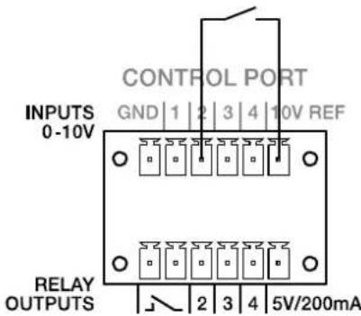
Control port with switch
Control Outputs
The lower part of the control port, which is marked as RELAY OUTPUTS on the N8000, provides different outputs. There are three freely programmable control outputs which are numbered in order from 2 to 4. These control outputs are designed as relays contacts (normally open), i.e. they are open when they are inactive (off) and closed towards ground when they are active (on). A voltage source at the 5V/200mA connection is available in order to operate the externally connected elements.
ATTENTION:
The maximum allowable current at the 5 V output is 200 mA.
The two left connections of the RELAY OUTPUTS are the READY/FAULT output of the N8000. This floating output is closed when the N8000 is ready for operation and no error has occurred. It is possible in IRIS-Net to configure which kind of error causes the contact to be opened. Due to this feature, this contact is especially suitable for the integration of the N8000 in life safety systems (closed current principle). An example application for the circuit of a control output is shown in the following figure. An operating state of the N8000 (e.g. the overstepping of a temperature limit) is indicated via a pilot light.
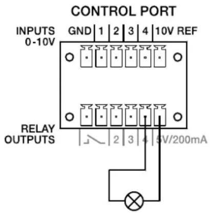
Control port with pilot light
Audio Interfaces
Analog audio connecting cable
It is advisable to choose balanced cables (2 signal conductors + shield) with XLR connectors as analog audio connections. Although all N8000 analog audio inputs and outputs can be used unbalanced, balanced audio cable is the better choice. A balanced differential audio circuit can prevent the injection of external noise into the audio path and is strongly recommended, particularly for long cable runs.

N8000 Analog audio input cable, XLR (female) on Phoenix

N8000 Analog audio output cable, XLR (male) on Phoenix
Digital audio connecting cable
It is advisable to choose balanced cables (2 signal conductors + shield) with XLR connectors as digital audio connections. Although all N8000 digital audio inputs can be used unbalanced, balanced audio cable is the better choice.

N8000 Digital (balanced) audio input cable, XLR (female) on Phoenix

N8000 Digital (unbalanced) audio input cable, Cinch (male) on Phoenix
4 Network configuration
4.1 Introduction
The N8000 system controller can be connected to a TCP/IP-network via the Ethernet interface at its rear panel (see page 13). For further information on the principles of Ethernet and TCP/IP please see the chapter Ethernet principles on page 33 in the appendix of this document.
The N8000 comes with the following network configurations from the factory:
| Parameter Value | |
| IP address | 192.168.1.100 |
| Subnet mask | 255.255.255.0 |
| Gateway | 192.168.1.1 |
| DHCP deactivated | |
An IP address must be unique, it must only be allocated to one single device (host) in a network. In case a new Ethernet network is designed for the operation of the N8000, it is recommended to retain the subnet mask and network ID which had been set at the factory. If the N8000 is integrated in an existing Ethernet network, the network configuration of the N8000 must be adapted.
The preset IP address of the N8000 can be retained if and only if
- only a single N8000 with factory-set configuration is connected via Ethernet and
- the network ID 192.168.1 can be retained and
- no other devices have the Host-ID 100.
If at least one of these three conditions is not fulfilled, the preset IP address of the N8000 has to be changed.
Example:
The following illustration shows an example application with four NetMax N8000 in a closed network. These are networked with a PC via a central Ethernet switch. Thus, the factory preset
IP address 192.168.1.100 would exist four times in the network. Because of this, the preset IP address of three NetMax N8000s must be replaced with a unique address.
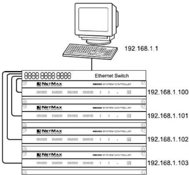
Example of an Ethernet network with four N8000
It is advantageous and strongly recommended to list all devices used in the Ethernet network and IP addresses for changing the preset IP addresses of the N8000s. An example of such a list for the example system shown in the above illustration is given in the following. You will find an empty form in the appendix. Please enter the description of the device, an unambiguous description and the IP address which has to be assigned to the device for every device used in the network in this list. If the device is displayed in IRIS-Net, you can also use the description that is used there.
| Device | IRIS-Net Device Name | Location/Description | IP-Adresse |
| N8000 main | office main office 192.168.1.100 | ||
| PC - main of | office 192.168.1.1 | ||
| N8000 admin | nistration administration building | 192.168.1.101 | |
| N8000 prod | uction production building 192. | 168.1.102 | |
| N8000 multi | -purpose mult-purpose hall | 192.168.1.103 |
When the example system is put into operation, the IP addresses which are given in the overview table, should be assigned to each device. The assignment of the IP address can be made via IRIS-Net and via the N8000 browser interface. In IRIS-Net the assignment is possible both over the USB interface and the Ethernet interface of the N8000. Information about the exact proceedings are given in the IRIS-Net online-help. For the assignment of the IP address over the N8000 browser interface open the browser interface using the current (preset) IP address of the N8000. Information about the exact proceedings are given in the N8000 browser manual.
4.2 Configuration
Configuration and testing of an Ethernet connection with N8000
The purpose of this procedure is to build a connection between a PC and a N8000 with factory network settings (see page 25) via Ethernet and to check the proper function of this connection. In the following it is assumed that neither the PC nor the N8000 are connected with an existing network.
1. Click on Start > Control Panel > Network Connection.
The window Network Connections appears. Here, all available possibilities for the connection of your PC with a network are given. The Ethernet connection that is used for the connection with the N8000 is contained in the LAN or High-Speed Internet category.
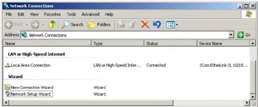
- Click on (with the right mouse button) that particular Ethernet connection in the Network Connections window that should be used for the connection with the N8000. The context menu of the chosen Ethernet connection appears.
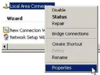
3. Click on Properties in the context menu.
The pop-up window Local Area Connection Properties appears.
![Local Area Connection Properties General | Authentication | Advanced | Connect using: 3Com EtherLink XL 10/100 PCI For C Configure... This connection uses the following items: ✓ Client for Microsoft Networks ✓ File and Printer Sharing for Microsoft Networks ✓ QoS Packet Scheduler ✓ Internet Protocol [TCP/IP] Install... Uninstall Properties Description Transmission Control Protocol/Internet Protocol. The default wide area network protocol that provides communication across diverse interconnected networks. ✓ Show icon in notification area when connected ✓ Notify me when this connection has limited or no connectivity OK Cancel](/content/2026/05/824965/images/1ca0013a006d761789420ed939f7b22880984921428db87e3b3c09093366eed8.jpg)
4. Double click on Internet Protocol (TCP/IP).
The pop-up window Internet Protocol (TCP/IP) Properties appears.
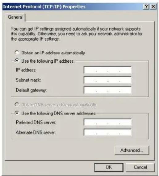
- Choose the option Use the following IP address in the window.
- Type 192.168.1.1 in the IP address input field.
-
Type 255.255.255.0 in the Subnet mask input field.
-
Close the window Internet Protocol (TCP/IP) Properties by clicking on the OK button.
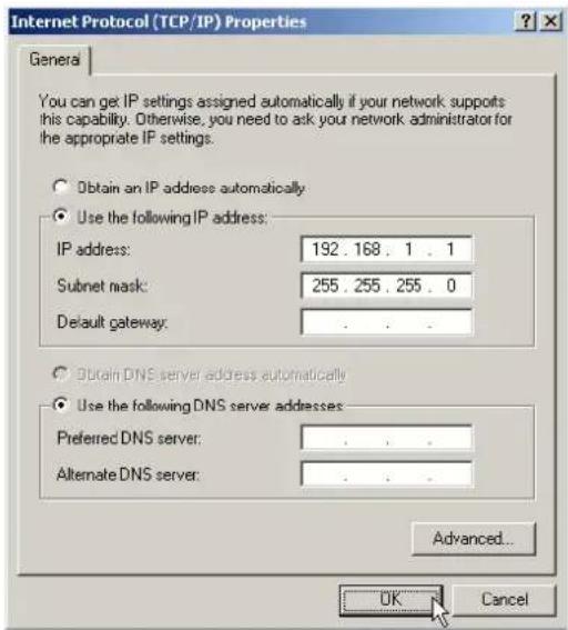
The IP configuration of the PC is now complete. In the following steps the connection of the PC with the N8000 will be established and checked.
- Connect the network connection of your PC to the Ethernet interface of the N8000 directly with a crossover cable, or with a patch cable and a hub/switch.
Please see the Ethernet principles chapter on page 33 in the appendix of this document for more information on the details of connecting devices via Ethernet.
- Connect the N8000 to the power supply system and switch it on by operating the power switch on the rear.
The green ON-LED (see page 11) on the front panel of the N8000 is illuminated. After some seconds the green READY-LED (see page 11) is also illuminated and signals the successful start activity of the N8000.
- Click on Start > All Programs > Accessories > Command Prompt. The window command prompt appears.
12. Enter ping 192.168.1.100 and tap the return button.
![Microsoft Windows XP [Version 5.1.2600] (C) Copyright 1985-2001 Microsoft Corp. C:\Documents and Settings\Administrator>ping 192.168.1.100 Pinging 192.168.1.100 with 32 bytes of data: Reply from 192.168.1.100: bytes=32 time=17ms TTL=64 Reply from 192.168.1.100: bytes=32 time<1ms TTL=64 Reply from 192.168.1.100: bytes=32 time=23ms TTL=64 Reply from 192.168.1.100: bytes=32 time=3ms TTL=64 Ping statistics for 192.168.1.100: Packets: Sent = 4, Received = 4, Lost = 0 (0% loss), Approximate round trip times in milli-seconds: Minimum = 0ms, Maximum = 23ms, Average = 10ms C:\Documents and Settings\Administrator>](/content/2026/05/824965/images/63647277b804269ec2067d6b1a2a638767fea0117a51eabe6d1bb98672fc6d37.jpg)
The PC is now checking the connection with the N8000. For this four network packets are sent to the N8000 via Ethernet then the N8000 has to confirm these packets. If the Ethernet connection is successful, no packets get lost. Therefore, 0% loss is stated in the ping statistics.
5 Appendix
5.1 Application Example
Installation in a multi-purpose hall
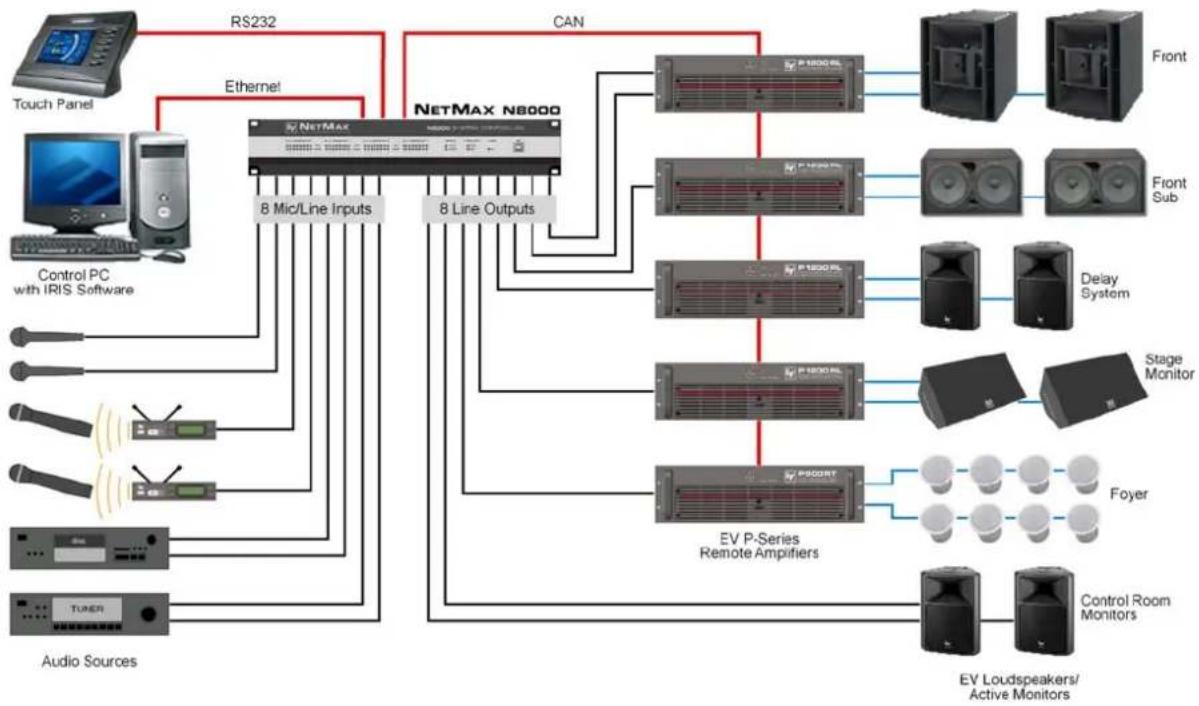
The following figure shows an example for the application of a N8000 system controller in a multi-purpose hall. Four microphones, one CD player and one tuner are the connected signal sources. Both active and passive speakers are used for the sound reinforcement. The Electro-Voice Precision Series Remote Amplifiers which are used for the operation of the passive speakers are connected with the N8000 via the CAN Bus in addition to the audio connections.
Two different methods are designed in order to operate and control the system. The first possibility is a conventional PC where the IRIS-Net (Intelligent Remote & Integrated Supervision) software is used to operate the N8000 and the remote amplifiers. It is not only possible to operate and control the system via IRIS-Net, but also to monitor the whole system. The N8000 and the PC are connected via Ethernet. Connecting a touch panel (e.g. AMX™, Crestron™) to the RS-232-interface of the N8000 is the second possibility for the operation of the system. The desired functions of the system can be accessed via the special operating interface of the touch panel.
flowchart
graph TD
    A["Touch Panel"] -->|RS232| B["NetMax N8000"]
    C["Control PC with IRIS Software"] -->|Ethernet| B
    D["Tuner"] -->|Audio Sources| B
    B -->|CAN| E["Front"]
    B -->|CAN| F["Front Sub"]
    B -->|CAN| G["Delay System"]
    B -->|CAN| H["Stage Monitor"]
    B -->|CAN| I["Foyer"]
    B -->|CAN| J["Control Room Monitors"]
    B -->|CAN| K["EV Loudspeakers/Active Monitors"]
    B -->|8 Mic/Line Inputs| L["NetMax"]
    B -->|8 Line Outputs| M["EV P-Series Remote Amplifiers"]
Installation in a multi-purpose hall
5.2 Troubleshootings
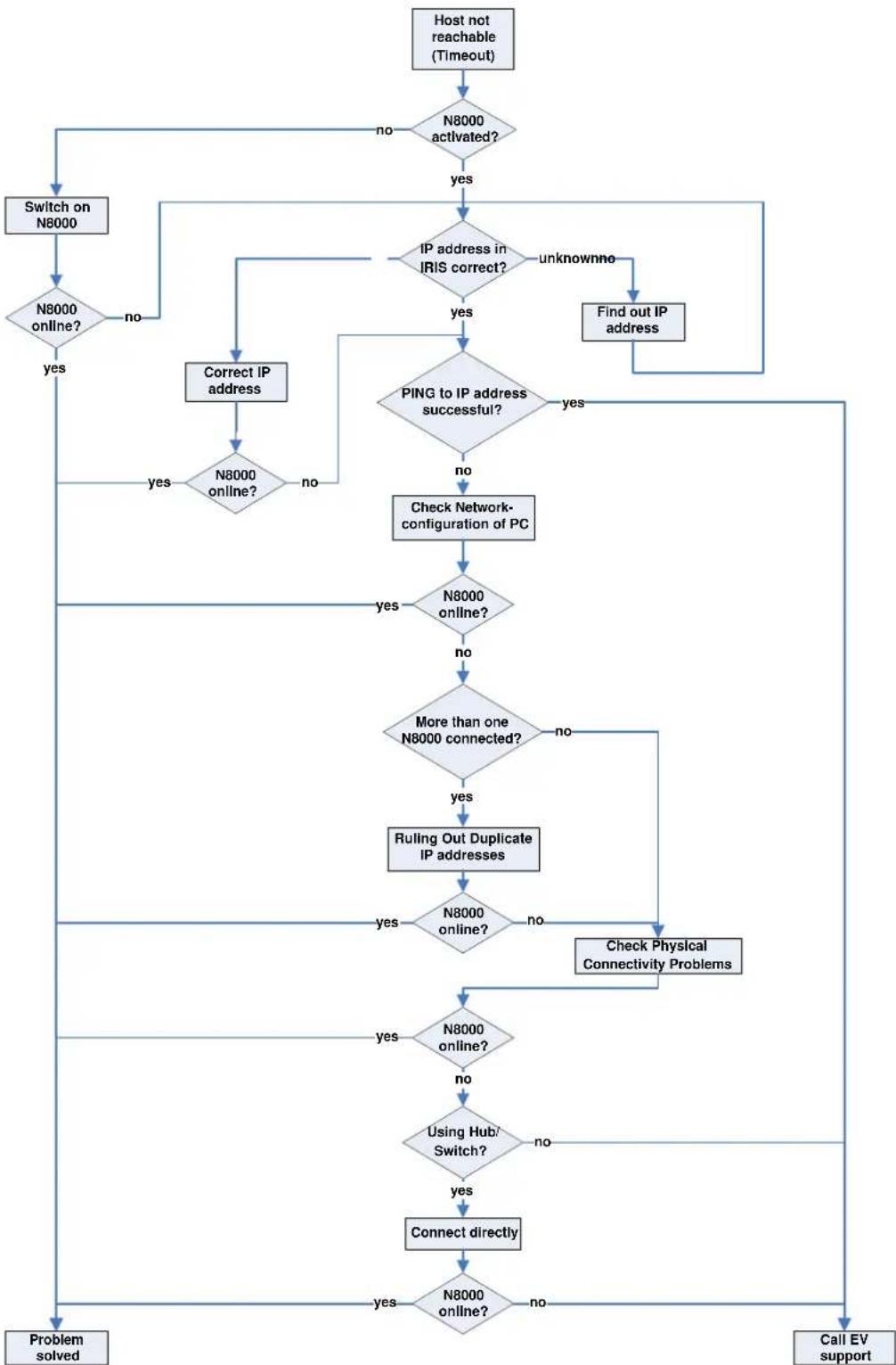
Problem: It is not possible to establish a connection with the N8000 via IRIS-Net.
flowchart
graph TD
    A["Host not reachable (Timeout)"] --> B{N8000 activated?}
    B -->|no| C["Switch on N8000"]
    B -->|yes| D{IP address in IRIS correct?}
    D -->|unknownno| E["Find out IP address"]
    D -->|yes| F{PING to IP address successful?}
    F -->|yes| G["Check Network-configuration of PC"]
    F -->|no| H{N8000 online?}
    H -->|yes| I["Correct IP address"]
    H -->|no| J{N8000 online?}
    J -->|yes| K["Switch on N8000 online"]
    J -->|no| L["More than one N8000 connected?"]
    L -->|yes| M["Ruling Out Duplicate IP addresses"]
    L -->|no| N{N8000 online?}
    N -->|yes| O["Check Physical Connectivity Problems"]
    N -->|no| P{N8000 online?}
    P -->|yes| Q["Using Hub/Switch?"]
    P -->|no| R["Connect directly"]
    Q -->|yes| S["Connect directly"]
    Q -->|no| T["Problem solved"]
    R --> U["Call EV support"]
    S --> V["Problem solved"]
Check Network Configuration of PC:
Check the network configuration of the used PC. Remember that the network part of the used IP addresses that is used and the subnet mask of the PC and the N8000 have to be identical.
Ruling Out Duplicate IP-Adresses:
It is possible that the same IP address is allocated twice if there are more devices in an Ethernet network and if the IP addresses are allocated manually. Switch off the N8000 and try to ping the IP address of the off-state N8000 via a command line prompt (see page 30 of this manual). If the ping is successful, another device has the address of the off-state N8000. In this case, change the IP address of the device which is now answering or of the N8000 with the duplicate address (then you also have to change the IP address of the N8000 in IRIS-Net).
Check Physical Connectivity Problems:
When the PC and the N8000 are connected physically via the Ethernet, the following points have to be checked:
- Is the network cable undamaged and plugged in correctly?
- Is - if necessary - a crossover cable used?
- Do the indicator lights of the network socket of the PC, the N8000 and (if available) of the network devices between the PC and the N8000 glow after the network cable(s) has/have been plugged in?
- Is a problem indicated on the used network interface in the system control devices of the operating system?
Connect directly:
Establish a direct connection between the PC and the N8000 via a crossover cable in order to rule out internal problems in the network devices between the PC and the N8000. If an IP address had been set up automatically (DHCP) via a network device which is now no longer connected, this address has to be set up manually again.
5.3 Ethernet principles
The N8000 system controller can be connected to an Ethernet network via the Ethernet interface (RJ-45) on the rear panel. Ethernet is a computer networking technology for local networks. It is possible to connect two devices (hosts) directly via a crossed Ethernet cable (crossover cable) if this is necessary. If more than two devices have to be connected, they have to be connected via normal Ethernet cables (straight through cables) and a central node (hub or switch). For this purpose the central hub or switch has an extension (port) for every network member. The Ethernet interface of the N8000 is compatible with the following Ethernet standards:
- 10Base-T (IEEE 802.3i): Four wires (two twisted pairs) of CAT-3 or CAT-5 cables are used for this connection. The transfer rate is 10 MBit/s and the maximal length of a segment is 100 meters.
- 100Base-TX (IEEE 802.3u): Two twisted wire pairs are used for the connection (see above). However, in this case, a CAT-5 cable has to be used. 100Base-TX has a transfer rate of 100 MBit/s and is the standard Ethernet implementation nowadays.
IP addresses
Diverse network protocols can be used for the communication of the devices connected to the Ethernet network. The N8000 uses the TCP/IP protocol, thus, it is an IP network device. IP addresses are used for the logical addressing of devices in an IP network. The N8000 uses version IPv4 (Internet protocol version 4) for the addressing. Therefore, the length of an IP address is 32 bit (= 4 Byte). 4.3 billion unique addresses are theoretically possibl with this protocol. Normally IPv4 addresses are given in the dotted decimal notation, i.e. the four bytes are written as four decimals separated by dots. Thus, the general notation of an IPv4 address is AAA.BBB.CCC.DDD. An example of an IP address is 130.009.122.195. Zeros which stand in the first place can be omitted. That is the reason why the exemplary address can also be written as: 130.9.122.195.
The following table shows address sequences that should be used in private networks.
| Class | Adress space | Subnet mask | CIDR | Number of IP addresses |
| A 10.0 | 0.0 - 10.255.255.255 | 255.0.0.0 10 | 0.0.0/8 16777216 | |
| B 172. | 16.0.0 - 172.31.255.255 | 255.240.0.0 1 | 72.16.0.0/12 1048576 | |
| C | 192.168.0.0 - 192.168.255.255 | 255.255.0.0 | 192.168.0.0/16 | 65536 |
| Link local | 169.254.0.0 - 169.254.255.255 | 255.255.0.0 | 169.254.0.0/16 | 65536 |
Private IP addresses are especially of interest in networks which are connected to the Internet. Private IP addresses are not routed in the Internet. Thus, it is necessary to make an address conversion with NAT (Network Address Translation) or PAT (Port Address Translation = NAT and additional change of the port number) in order to be able to access the Internet. An benefit of this is that it is possible to connect several devices via a router with the Internet even when your Internet provider has only allocated one IP address. Additionally, the real IP address of the devices can be hidden from hackers by NAT/PAT (Security through Obscurity).
Subnet mask
An IP address is always divided into a network part (network address/ID) and a host part (host address/ID or device address). Devices are in the same network if, and only if, the network parts of their addresses are identical. Devices can interact directly with each other if they are in the same network. Ancillary equipment (e.g. a router) is necessary if devices in different networks should interact. Within one network host addresses may not be allocated twice.
For example, a network could e.g. split the 4 Byte (32 bit) of an IP address in a 3 Byte long network part and in 1 Byte long host part. The exact partitioning between network part and host part is given in the form of subnet masks. In this case, the partitioning of the first 24 bits or the last 8 bits would be made because of the subnet mask 255.255.255.0.
The CIDR notation which is designed to display a subnet mask is an alternative to the dotted decimal notation. So called suffixes are used in the CIDR notation. The suffix indicates the number of 1-bits in the subnet mask. Thus, the subnet mask 255.255.255.0 in dotted decimal notation would correspond to the suffix /24 as the first 24 places (in binary description) of an IP address are chosen as network address.
It is possible to impact the maximum number of the devices addressable within a network by choosing the subnet mask which results in different partitioning of the IP address in network part and in host part. For the exact number it has to be considered that the host part may neither be completely zero nor completely 1 in the binary description.
Example: In case of the above-mentioned example IP address 130.9.122.195 the network part would be 130.9.122.0 by using the subnet mask 255.255.255.0. So, each device (or interface) in the considered network uses an address of the type 130.9.122.DDD. As the values 00000000 and 11111111 are excluded for the host part DDD in binary description, the corresponding decimal values 1 to 254 for DDD are allowed. Thus, a maximum of 254 different devices can be addressed in a network and the corresponding addresses are 130.9.122.1 to 130.9.122.254.
Automatic/Manual Allocation of IP Addresses
IP addresses can be allocated both automatically and manually to a device in a network. If the address is allocated automatically via DHCP (Dynamic Host Configuration Protocol), the operation of a DHCP server in the network is necessary. This server makes it possible to dynamically allocate an IP address and additional configuration parameter to hosts in a network. The use of a DHCP server is especially useful for networks in which devices are often connected and removed.
If DHCP is used, certain incidents (e.g. the reboot of a device) can result in the change of the IP address of this device. If this device is a N8000 system controller, its configuration in IRIS-Net has to be modified to reflect the changed IP address. For that reason it is not advisable to use DHCP for the dynamic configuration of N8000. Instead, of that the network configuration of the N8000 should be done manually.
When a new Ethernet network which will not be connected to the Internet is established, any network part of the IP addresses can be defined. By choosing the appropriate subnet mask it is possible to adapt the number of the addressable devices to your requirements.
Please contact your network administrator regarding details on the correct network configurations if one or several N8000 is/are integrated in an existing Ethernet network (with or without DHCP server) or if the network is connected to the Internet.
5.4 CAN-Bus Principles
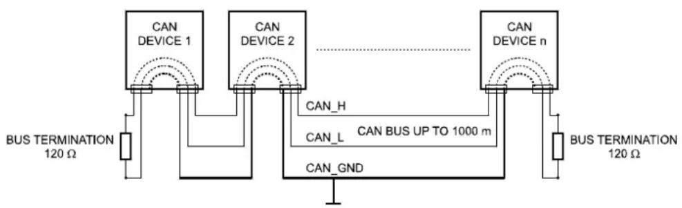
The network topology used by the CAN bus is based on the so-called “bus or line topology”, i.e. all participants are connected via a single two-wire cable (Twisted-Pair cable, shielded or unshielded) with the cabling running from one participant on the bus to the next, allowing unlimited communication among all devices. In general, it does not matter if the bus member is a power amplifier, a N8000 or a UCC1 USB-CAN converter. Thus, the N8000 can be connected at any place of the CAN bus. In total, up to 100 devices can be connected to one CAN bus.
The CAN bus has to be terminated with a 120 Ω terminating resistor at both ends. If the termination is missing or an improper resistor value is used, network errors can occur as a signal is reflected on the bus at both bus ends. Because of the superposition of the reflection with the original signal, the original signal is blurred. This may result in the loss of data. In order to prevent or minimize reflections at the bus ends, terminators are used as they "absorb" the energy of the signal.
Since the CAN interfaces of all EVI Audio appliances are galvanically separated from the rest of the circuitry, network cabling also carries a common ground conductor (CAN_GND) ensuring that all CAN-interfaces in the network are connected to a common ground potential.
flowchart
graph TD
    A["CAN DEVICE 1"] -->|CAN_H| B["CAN DEVICE n"]
    C["CAN DEVICE 2"] -->|CAN_L| B
    D["BUS TERMINATION 120 Ω"] --> E["CAN GND"]
    F["BUS TERMINATION 120 Ω"] --> G["CAN GND"]
    B --> H["CAN BUS UP TO 1000 m"]
    style A fill:#f9f,stroke:#333
    style C fill:#f9f,stroke:#333
    style D fill:#f9f,stroke:#333
    style F fill:#f9f,stroke:#333
    style B fill:#ccf,stroke:#333
    style G fill:#ccf,stroke:#333
Bus Topology of the CAN bus
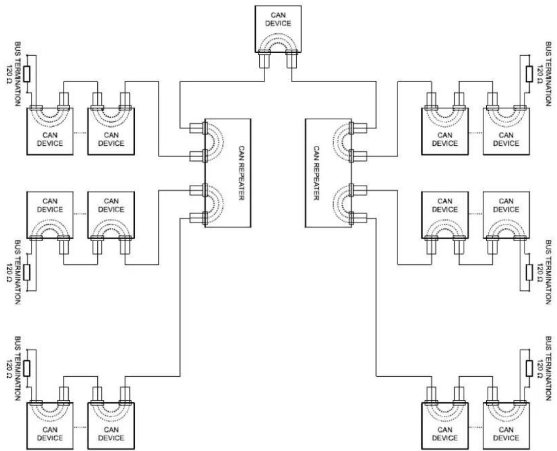
By using a CAN bus repeater a connection between two independent and self-contained CAN bus systems can be created. Thus, the following can be achieved:
- Increase of the max. number of members
A maximum of 100 devices can be connected to one CAN bus. This number can be increased up to 250 by connecting several CAN bus systems. This limitation of exactly 250 devices results from the addressing scheme used by the CAN bus. The addressing scheme allows the allocation of a maximum of 250 different CAN device addresses.
- Improvement of signal quality
With CAN bus systems, whose bus length exceeds 1000 meters, a CAN bus repeater should be used. The CAN bus repeater accomplishes a signal processing and a reinforcement of the
bus signals. The internal running time of the repeaters of approx. 150 ns corresponds to an extension of the bus over approx. 45 meters.
- Creation of alternative network topologies
By using one or several repeaters, not only the above-mentioned bus topology, but the creation of other network topologies are also possible. In the following figure a star topology from three independent CAN bus systems is given as example. The three CAN buses are connected via two repeaters.
flowchart
graph TD
    A["CAN DEVICE"] --> B["CAN DEVICE"]
    A --> C["CAN REPEATER"]
    A --> D["CAN DEVICE"]
    A --> E["CAN DEVICE"]
    F["CAN DEVICE"] --> G["CAN DEVICE"]
    F --> H["CAN REPEATER"]
    F --> I["CAN DEVICE"]
    F --> J["CAN DEVICE"]
    K["CAN DEVICE"] --> L["CAN DEVICE"]
    K --> M["CAN REPEATER"]
    K --> N["CAN DEVICE"]
    K --> O["CAN DEVICE"]
    P["CAN DEVICE"] --> Q["CAN DEVICE"]
    P --> R["CAN REPEATER"]
    P --> S["CAN DEVICE"]
    P --> T["CAN DEVICE"]
    U["CAN DEVICE"] --> V["CAN DEVICE"]
    U --> W["CAN REPEATER"]
    U --> X["CAN DEVICE"]
    U --> Y["CAN DEVICE"]
    Z["CAN DEVICE"] --> AA["CAN DEVICE"]
    Z --> AB["CAN REPEATER"]
    Z --> AC["CAN DEVICE"]
    Z --> AD["CAN DEVICE"]
    AE["CAN DEVICE"] --> AF["CAN DEVICE"]
    AE --> AG["CAN REPEATER"]
    AE --> AH["CAN DEVICE"]
    AE --> AI["CAN DEVICE"]
    AJ["CAN DEVICE"] --> AK["CAN DEVICE"]
    AJ --> AL["CAN REPEATER"]
    AJ --> AM["CAN DEVICE"]
    AJ --> AN["CAN DEVICE"]
    AO["CAN DEVICE"] --> AP["CAN DEVICE"]
    AO --> AQ["CAN REPEATER"]
    AO --> AR["CAN DEVICE"]
    AO --> AS["CAN DEVICE"]
    AT["CAN DEVICE"] --> AU["CAN DEVICE"]
    AT --> AV["CAN REPEATER"]
    AT --> AW["CAN DEVICE"]
    AT --> AX["CAN DEVICE"]
    AY["BUS TERMINATION 120 Ω"] --> AZ["BUS TERMINATION 120 Ω"]
    BA["BUS TERMINATION 120 Ω"] --> BB["BUS TERMINATION 120 Ω"]
System Examples
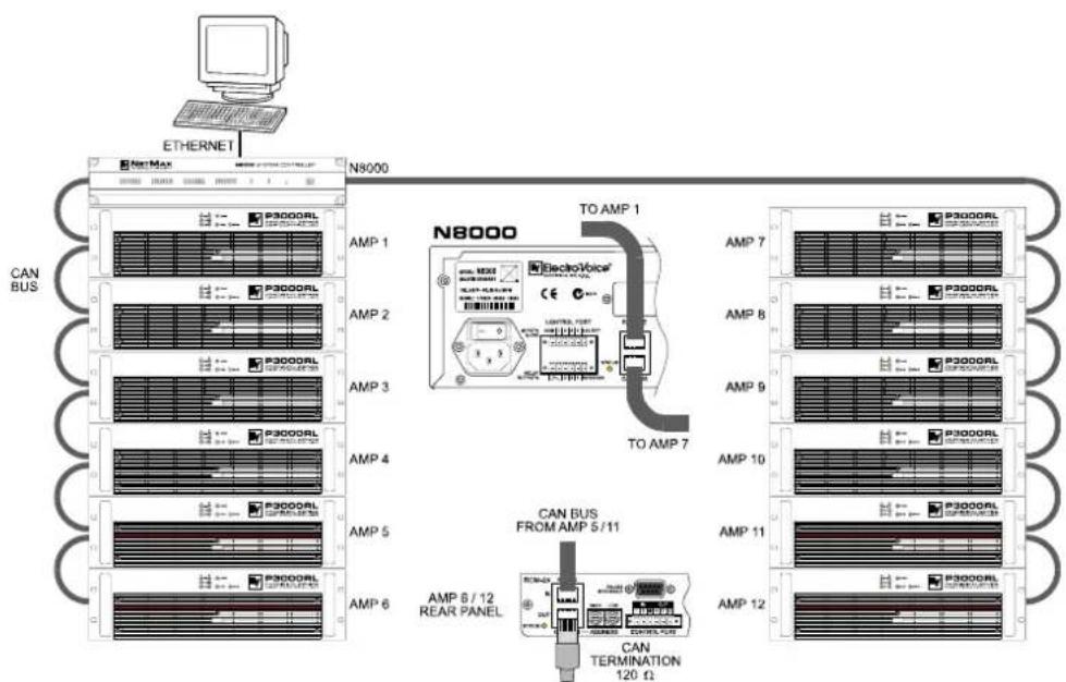
The following illustrations show examples of the data-bus wiring for different sizes of CAN-bus networks..

System with 5 power amps and 1 N8000 at the beginning of the bus. Termination plugs at the N8000 (first unit on the bus) and at amp 5 (last unit on the bus).
flowchart
graph TD
    A["ETHERNET"] --> B["N8000"]
    B --> C["N8000 ElectroVoice"]
    C --> D["TO AMP 1"]
    C --> E["TO AMP 7"]
    C --> F["TO AMP 12"]
    style A fill:#f9f,stroke:#333
    style B fill:#ccf,stroke:#333
    style C fill:#cfc,stroke:#333
    style D fill:#fcc,stroke:#333
    style E fill:#fcc,stroke:#333
    style F fill:#fcc,stroke:#333
    subgraph Legend
        G["P3000RL"]
        H["P3000RL"]
        I["P3000RL"]
        J["P3000RL"]
        K["P3000RL"]
        L["P3000RL"]
        M["P3000RL"]
        N["P3000RL"]
        O["P3000RL"]
        P["P3000RL"]
        Q["P3000RL"]
        R["P3000RL"]
        S["P3000RL"]
        T["P3000RL"]
        U["P3000RL"]
        V["P3000RL"]
        W["P3000RL"]
        X["P3000RL"]
        Y["P3000RL"]
        Z["P3000RL"]
        AA["P3000RL"]
        AB["P3000RL"]
        AC["P3000RL"]
        AD["P3000RL"]
        AE["P3000RL"]
        AF["P3000RL"]
        AG["P3000RL"]
        AH["P3000RL"]
        AI["P3000RL"]
        AJ["P3000RL"]
        AK["P3000RL"]
        AL["P3000RL"]
        AM["P3000RL"]
        AN["P3000RL"]
        AO["P3000RL"]
        AP["P3000RL"]
        AQ["P3000RL"]
        AR["P3000RL"]
        AS["P3000RL"]
        AT["P3000RL"]
        AU["P3000RL"]
        AV["P3000RL"]
        AW["P3000RL"]
        AX["P3000RL"]
        AY["P300GAL"]
        AZ["P30GAL"]
        BA["P3GAL"]
        BB["P3GAL"]
        BC["P3GAL"]
        BD["P3GAL"]
        BE["P3GAL"]
        BF["P3GAL"]
        BG["P3GAL"]
        BH["P3GAL"]
        BI["P3GAL"]
        BJ["P3GAL"]
        BK["P3GAL"]
        BL["P3GAL"]
        BM["P3GAL"]
        BN["P3GAL"]
        BO["P3GAL"]
        BP["P3GAL"]
        BPB["P3GAL"]
        BPBb["P3GAL"]
        BPBbP["TO AMP 1"]
        BPBbPb["TO AMP 7"]
    end
System with 2 amp-racks and 1 N8000/PC in the middle. Termination plugs at power amp 6 (first unit on the bus) and power amp 12 (last unit on the bus).
Performance Specifications
According to the ISO 11898-2 standard, CAN-bus data transfer cabling has to be carried out using Twisted-Pair cables with or without shielding providing a characteristic impedance of 120 Ω. Both ends of a CAN-bus need to be terminated with 120 Ω termination-plugs. The maximum bus-length depends on the actual data transfer rate, the kind of data transfer cable being used, as well as the total number of participants on the bus. The following table shows the most essential requirements for CAN-networks consisting of up to 64 participants.
| Bus Length (in m) | Date Transmission Cable | Termination (in Ω) | Max. Data Transfer Rate | |
| Resistance per Unit Length (in mΩ/m) | Cable Diameter | |||
| 0...40 < 70 0 | 25...0,34 mm2 | AWG23, AWG22 | 124 1000 kbit/s at 40 m | |
| 40...300 < 60 | 0,34...0,6 mm2 | AWG22, AWG20 | 127 500 kbit/s at 100 m | |
| 300 ... 600 < 40 | 0,5...0,6 mm2 | AWG 20 | 150...300* 100 kbit/s at 500 m | |
| 600...1000 < 26 | 0,75...0,8 mm2 | AWG 18 | 150...300* 62,5 kbit/s at 1000 m | |
* With longer cables and many participants on the CAN-bus, termination resistors with higher impedance than the specified 120 Ω are recommended to reduce the ohmic load of the interface drivers and therefore the voltage drop between the two cable-ends.
The following table is meant for first assessment of necessary cable diameters for different bus lengths and bus-participant numbers.
Additionally, the length of branch lines - for participants that are not directly connected to the CAN-bus - is also of importance. For data transfer rates of up to 125 kbit/s, the maximum length of a single stub cable should not exceed 2 meters. For higher bit rates a maximum length of only 0.3 meter is still permissible. The entire length of all branch lines should not exceed 30 meters.
General Note:
- As long as only short distances (up to 10 meters) are concerned, common RJ-45 patch cables with a characteristic impedance of 100 (AWG 24 / AWG 26) can be used for the cabling inside of a rack mounted system.
- The previously outlined guidelines for network cabling are mandatory as far as the rack mounted shelve interconnection or fixed installations are involved.
5.5 IP Address Table
Project:
| Subnet mask | |
| Gateway |
| Device IRIS-Net Device Name Location / Description IP Address | |||
| GENERAL DESCRIPTION AND FEATURES | |
| N8000 System Controller Modular NetMax system manager including signal processing, routing, system control and supervision | |
| Audio 32 Audio Channels | 4 Audio Slots, modular8-Channel Input and Output cards, analog or digital |
| Networking Module Slot for optional CobraNetTM Interface32 I/O Audio and Control | |
| Safety / Redundancy Internal Supervision, System Monitoring, Watchdog, FaultOutput, Redundant Audio Network possible | |
| PC Configuration and Control Software | IRIS-Net - Intelligent Remote & Integrated SupervisionIntegration of N8000, Remote Amplifiers, peripheral controlConfiguration, Control and Supervision for complete Audio SystemsFreely programmable User Control Panels and Access Levels |
| AUDIO SPECIFICATIONS | |
| Audio Inputs - Analog Input Module AI-1 | 8 analog audio inputs per module, line level, electronically balanced |
| Connectors 8 x 3-pole Euro block connectors | |
| Input Level (nominal) +6 dBu / 1.55 V | |
| Input Level (max. before clip) +21 dBu / 8.7 V | |
| Input Impedance 20 kΩ | |
| Common Mode Rejection > 70 dB | |
| A/D Conversion 24 Bit, Sigma-Delta, 128 times oversampling | |
| Audio Outputs - Analog Output Module AO-1 | 8 analog audio outputs per module, line level, electronically balanced |
| Connectors 8 x 3-pole Euro block connectors | |
| Output Level (nominal) | +6 dBu / 1.55 V |
| Output Level (max. before clip) | +21 dBu / 8.7 V |
| Output Impedance | 100 Ω |
| Min. Load Impedance | 600 Ω |
| D/A Conversion 24 Bit, Sigma-Delta, 128 times oversampling | |
| Frequency Response | 20 Hz...20 kHz (-0.5 dB) |
| Signal to Noise Ratio (A-weighted) | AI-1: 117 dB typicalAO-1: 118 dB typicalN8000 analog In to analog Out: 115 dB typical |
| THD+N | < 0.005 % |
| Signal Delay | AI-1: 1.3958 msAO-1: 0.646 msN8000 analog In to analog Out: 2.2917 ms |
| Crosstalk | <-110 dB @ 1 kHz |
| SIGNAL PROCESSING | |
| Sample Rate 48 kHz internal | 32 kHz - 192 kHz external |
| Data Format 24 Bit linear A/D and D/A conversion, 48 Bit processing | |
| Signal Processing 2 DSPs Standard (150 MHz, 300 MIPS) | |
| INTERFACES | |
| Ethernet 10 / 100 MBit/s, RJ-45 (PC Control) | |
| CAN 10... 500 kbit/s, 2 x RJ-45 (Remote Amp | Control) |
| RS-232 2 Ports, 9pin D-Sub female (Remote | Control) |
| USB USB Type B on Front Panel (PC Control) | |
| GPIO Control Port 2 x 6-pole Euro block | 4 Control Inputs (analog 0 - 10 V / logic control)3 Control Outputs (Relay contact to ground)1 Fault Output (NC Relay contact)3 Reference Outputs (+5 V / +10 V / GND) |
| N8000 GENERAL SPECIFICATIONS | |
| Power Supply 100 - 240 V AC, 50/60 Hz | |
| Power Consumption 90 W max. (incl. 2 x AI-1) | 2 x AO-1, 1 x CM-1 modules) |
| Safety Class I | |
| Cooling Left-to-right, 3-stage fan | |
| Operating Temperature Range 0 °C ... 40 °C | |
| Dimensions (W x H x D) 483 x 88.1 x 381 mm | (19“, 2 HU) |
| Weight N8000 (without optional modules): 7.3 | 5 kgAI-1 Analog Input Module: 200 gAO-1 Analog Output Module: 260 gCM-1 CobraNetTM Module: 75 g |
| MODULES / OPTIONS | |
| AI-1 Analog Input Module | 8 analog audio inputs, line level, electronically balanced |
| AO-1 Analog Output Module | 8 analog audio outputs, line level, electronically balanced |
| CM-1 CobraNetTM Module | 32 digital audio inputs and outputs, 2 CobraNetTM ports (Primary / Secondary) for network redundancy |
| DSP-1 DSP Extension Module | Internal DSP processing power and Delay-RAM extension, 300 MIPS, 256k x 24 SRAM |
| MI-1 Microphone Input Module | 8 microphone inputs, programmable Gain and Phantom Power, PAD for line level switching |
| DI-1 Digital Input Module | 8 digital audio inputs, AES/EBU, S/PDIF and Optical formats, sample rate converters for 32-192 kHz operation |
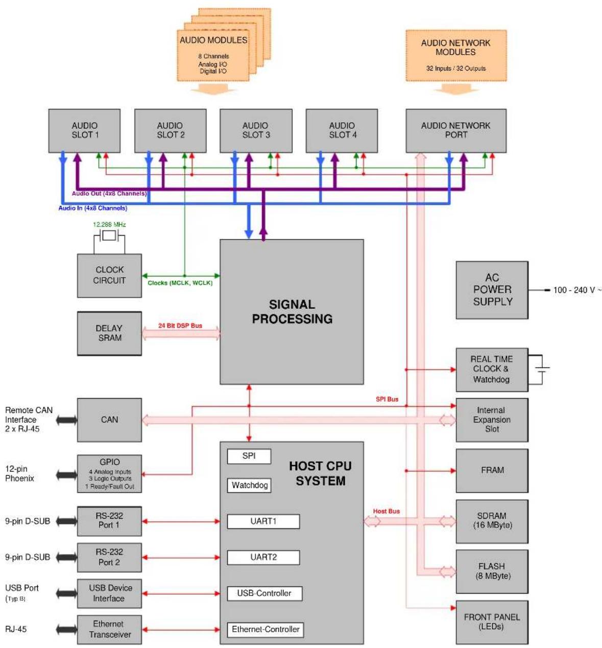
6.2 Block Diagram/Blockschaltbild
flowchart
graph TD
    A["Audio MODULES\n8 Channels\nAnalog I/O\nDigital I/O"] --> B["Signal Processing"]
    C["Audio NETWORK MODULES\n32 Inputs / 32 Outputs"] --> B
    B --> D["AC POWER SUPPLY"]
    D --> E["REAL TIME CLOCK & Watchdog"]
    E --> F["Internal Expansion Slot"]
    F --> G["FRAM"]
    G --> H["SDRAM (16 MByte)"]
    H --> I["FLASH (8 MByte)"]
    I --> J["FRONT PANEL (LEDs)"]
    B --> K["CAN"]
    B --> L["CLOCK CIRCUIT"]
    B --> M["DELAY SRAM"]
    B --> N["GPIO 4 Analog Inputs\n3 Logic Outputs\n1 Ready/Fault Out"]
    B --> O["RS-232 Port 1"]
    B --> P["RS-232 Port 2"]
    B --> Q["USB Device Interface"]
    B --> R["Ethernet Transceiver"]
    B --> S["Remote CAN Interface\n2 x RJ-45"]
    B --> T["12-pin Phoenix"]
    B --> U["SPI Watchdog"]
    B --> V["Host CPU SYSTEM"]
    B --> W["Clocks (MCLK, WCLK)"]
    W --> X["Audio In (4x8 Channels)"]
    X --> Y["Audio Out (4x8 Channels)"]
    Y --> Z["Audio In (4x8 Channels)"]
    Z --> A
6.3 Dimensions/Abmessungen
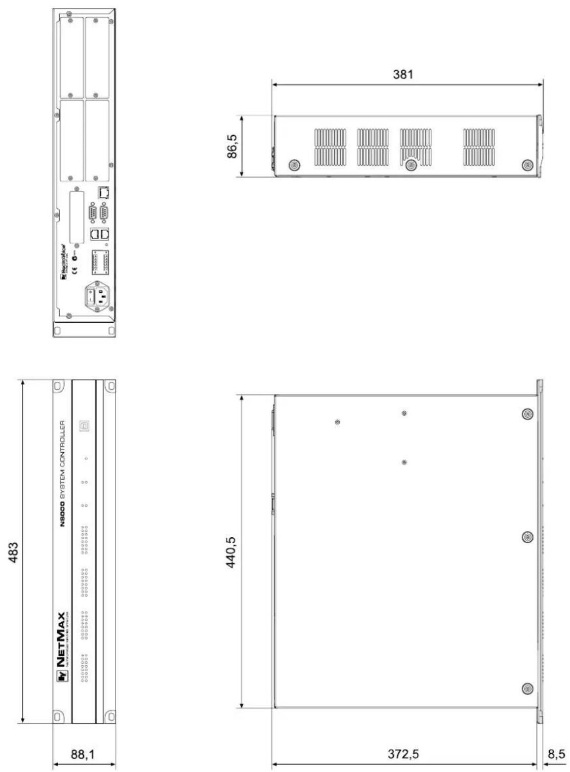
Notes
Notes
Notes
Notes
Ev ElectroVoice®
USA: Telex Communications Inc., 12000 Portland Ave. South, Burnsville, MN 55337, Phone: +1 952-884-4051, FAX: +1 952-884-0043
Germany: EVI Audio GmbH, Hirschberger Ring 45, D 94315, Straubing, Germany, Phone: +49 9421-706 0, FAX: +49 9421-706 265
France: EVI Audio France, Parc de Courcerin, Allée Lech Walesa, 77185 Lognes, France, Tél : +33 1 6480 0090, FAX: +33 1 6006 5103
Subject to change without prior notice.
Printed in Germany
V1.2
5/18/06 / D 362 478

- Control Elements and Connections .....10
- Preparations 15
- Network configuration 25
- Appendix 31
- IMPORTANT SAFETY INSTRUCTIONS
- IMPORTANT SERVICE INSTRUCTIONS
- HF-Interference
- Introduction
- Description of the system
- N8000 features
- Unpacking and warranty
- Installation instruction
- ATTENTION:
- IRIS-Net
- Browser Interface
- Control Elements and Connections
- Front Faceplate
- SIGNAL / PEAK-LEDs
- NETWORK-LEDs
- SYSTEM STATUS-LEDs
- SYSTEM STATUS
- POWER-LED
- POWER
- USB Interface
- Rear Panel
- AUDIO SLOTs
- Network Module Slot
- ETHERNET Interface
- RS-232 Interfaces
- REMOTE CAN BUS
- CONTROL PORT
- Mains Connector and Power Switch
- Preparations
- Mounting
- Install the expansion cards.
- Connect the power cable.
- Install the program IRIS-Net (Intelligent Remote & Integrated Supervision) on your PC.
- If you have installed expansion cards with inputs or outputs (AI-1, AO-1 or CM-1) in step 1, connect the corresponding devices now.
- Connect the Ethernet interface of the N8000 with the PC via an appropriate Ethernet cable.
- If your application also utilizes Electro Voice P-series Remote Control amplifiers, connect the CAN interface of the N8000 with the amplifiers.
- Switch on the N8000 (via the power switch at the rear), the computer and any additional connected devices, if used.
- Now start the IRIS-Net program on your PC.
- Installation of expansion cards
- System expansion with analog/digital inputs or outputs
- System expansion with a network module
- Expansion of the DSP performance of the system
- Interface description
- CAN Interface
- USB connection
- RS-232 Interface
- Control Inputs
- Control Outputs
- Audio Interfaces
- Analog audio connecting cable
- Digital audio connecting cable
- Network configuration
- Introduction
- Example:
- Configuration
- Configuration and testing of an Ethernet connection with N8000
- Click on Start > Control Panel > Network Connection.
- Click on Properties in the context menu.
- Double click on Internet Protocol (TCP/IP).
- Enter ping 192.168.1.100 and tap the return button.
- Appendix
- Application Example
- Installation in a multi-purpose hall
- Troubleshootings
- Check Network Configuration of PC:
- Ruling Out Duplicate IP-Adresses:
- Check Physical Connectivity Problems:
- Connect directly:
- Ethernet principles
- IP addresses
- Subnet mask
- Automatic/Manual Allocation of IP Addresses
- CAN-Bus Principles
- System Examples
- Performance Specifications
- General Note:
- IP Address Table
- Block Diagram/Blockschaltbild
- Dimensions/Abmessungen
- Ev ElectroVoice®
Brand : ELECTRO-VOICE
Model : NetMax N8000
Category : Uncategorized