
DMP2 - Audio Preamplifier M-AUDIO - Free user manual and instructions
Find the device manual for free DMP2 M-AUDIO in PDF.


| Product Type | Two-channel Microphone/Instrument Pre-Amplifier |
| Form Factor | Half-rack, 1U |
| Weight | Under 1 lb (approx. 0.45 kg) |
| Power Supply | 9V AC, 500mA, 2.5mm plug (included) |
| Microphone Inputs | 2 x XLR, balanced, low impedance |
| Instrument Inputs | 2 x 1/4" TS, high impedance (100k ohms) |
| Outputs | 2 x 1/4" TRS, selectable balanced or unbalanced |
| Gain Range (XLR) | Up to 70 dB |
| Gain Range (Instrument) | Up to 50 dB |
| Frequency Response | 31.5 Hz - 80 kHz (+/- 0.1 dB) balanced output |
| Total Harmonic Distortion (THD) | < 0.0015% (unbalanced), < 0.0065% (balanced) |
| Signal-to-Noise Ratio | > 99 dB (unbalanced), > 85 dB (balanced) |
| Low-Cut Filter | 3-pole, -18 dB/octave, cutoff at 72 Hz |
| Phantom Power | +48V, switchable for both XLR inputs |
| Phase Inversion | Individual switches per channel, 180-degree |
| Indicators | Signal (Sig) and Clip LEDs per channel, Power LED, Phantom Power LED, Low-Cut LED |
| Output Impedance | 500 ohms |
| Headroom | 20 dB |
| Maximum Output (Balanced) | 24 dBv |
| Maximum Output (Unbalanced) | 10 dBv |
| Warranty | Limited lifetime warranty (original purchaser, registration required) |
Frequently Asked Questions - DMP2 M-AUDIO
User questions about DMP2 M-AUDIO
0 question about this device. Answer the ones you know or ask your own.
Ask a new question about this device
Download the instructions for your Audio Preamplifier in PDF format for free! Find your manual DMP2 - M-AUDIO and take your electronic device back in hand. On this page are published all the documents necessary for the use of your device. DMP2 by M-AUDIO.
USER MANUAL DMP2 M-AUDIO
Front & Rear Panels 2
DMP2 Operation 4
Setting The Gain 4
Low-Cut Rumble Filter 5
Phase Inversion 5
Phantom Power 5
Balanced vs. Unbalanced Outputs....6
Specifications 7
Limited Lifetime Warranty 8
Introduction
Thank you for your purchase of the M Audio DMP2 Microphone/Instrument Pre-Amplifier. M Audio's proven mixer and pre-amp technology has reached its pinnacle with the DMP2, delivering a clarity and brilliance of audiophile integrity.
The DMP2 gives you two completely independent channels of high gain, ultra low noise pre-amps in a sturdy 1/2 rack space unit of exceptional design and quality. Each channel provides low impedance microphone inputs on XLR connectors with optional phantom power, plus an alternate high impedance instrument input on 1/4" TS jacks. The DMP2 outputs can be used as balanced or unbalanced via a TRS jack.
Microphones, guitars with magnetic or piezo pickups, and any instrument that needs a boost in gain to "line level" will benefit from the punch, yet ultimate transparency of the DMP2. High pass "rumble" filters for each channel eliminate unwanted low-end noise, while individual phase inversion switches ensure that you will always achieve the greatest result when using the DMP2 in a stereo or dual mic situation.
DMP2 Features
• 2 independent XLR, fully balanced mic inputs.
- 2 alternate, independent 1/4" unbalanced, high impedance inputs, impedance matched for ideal performance with electric and acoustic guitars and other high impedance mics or instruments.
- Exceptional frequency response, extremely flat throughout all frequencies.
- Separate low-cut filters for each channel with switch and LED indicator.
- S separate gain controls for each of the pre-amplifiers.
- Individual signal and clipping LEDs for each pre-amplifier channel.
- XLR 48v phantom power can be switched on or off for both mic inputs, with an LED indicator.
- Dual-purpose independent 1/4" outputs accept either tip-ring-sleeve plugs for balanced outputs or tip-sleeve plugs for unbalanced outs.
- Individual phase inversion switches for each channel.
- Half rack size.
Front & Rear Panels
Front Panel

-
Gain Adjustment Knobs: Separate gain controls for pre-amps 1 and 2 adjust the output volume levels independently. Full counter-clockwise is the minimum gain position, while full clockwise is maximum gain.
-
Signal & Clip LEDs: The "Sig" LED, when lit, indicates the presence of input signal either at the XLR mic input or 1/4'' high impedance input jacks. The "Clip" LED will light when that input signal is too strong and is about to distort, or clip (2dB below clipping). If this LED remains lit for more than a few moments, reduce the gain adjustment knob setting.
-
Low Cut Filter Switch: Pressing and locking this switch to the 'In' position engages the Low-Cut filter for the associated channel. Pressing and releasing to the 'Out' position disengages the filter.
-
Low-Cut Filter LED: When lit, this LED indicates that the Low-Cut filter has been engaged.
-
Phase Inversion Switch: This switch will invert the phase of the signal for the selected channel 180 degrees (see section, "Phase Inversion").
-
Phantom Power LED: When lit, this LED indicates that phantom power has been switched on for both of the mic pre-amp channels.
-
Main Power LED: When the proper power supply is applied to the DMP2 and the Main Power switch is switched to the 'On' position, this LED will light, indicating that the unit is powered up.
-
Main Power Switch: This switch, when pressed and locked to the 'In' position, switches the DMP2 power on.

-
9vAC Power Supply Jack: This power jack accepts a 9v AC 500mA 2.5mm power supply. This power supply is included with your DMP2, and ONLY the proper supply should be used.
-
Output Jacks 1 and 2: These 1/4" TRS jacks are the main outputs for the pre-amps. Using a TRS (tip-ring-sleeve), or 'stereo' 1/4" plug, the DMP2 will provide a balanced line-level output. Using a TS (tip-sleeve) 1/4" plug, the outputs will be unbalanced.
- Phantom Power Switch: When this button is pressed and locked to the 'In' position, phantom power (48v) will be sent to both XLR In 1 and XLR In 2.
- High Impedance Instrument Inputs: These high impedance (100k Ohm) inputs are optimized for guitars or high impedance microphones. When an instrument is plugged into this jack, the corresponding channel's XLR input is disabled.
- Microphone Inputs 1 and 2: These are the balanced, low impedance microphone inputs to the pre-amp channels. NOTE: When phantom power is engaged, power is sent to the ground wire on BOTH of these channels. When an instrument is plugged into the 1/4" jacks, the corresponding XLR jack is disabled.
DMP2 Operation
It is conceivable that once the DMP2 is attached to your system and powered up, you will be plugging and unplugging different microphones and instruments. Follow this simple procedure, then make sure that the gain controls on the DMP2 are at their lowest levels when attaching or changing mics or instruments.
- Plug in the 9v "wall wart" power supply into the wall receptacle, and the other end into your DMP2 9v power jack.
- Make the necessary connections from the outputs of the DMP2 to the inputs of your computer sound card, mixer (use the line level inputs), or sound system's power amp. NOTE: If your target device accepts a balanced signal either on a TRS or XLR jack, use a TRS plug (tip-ring-sleeve, typically a stereo plug) on the outputs of the DMP2. If your target device accepts only an unbalanced line in, then use a 'TS' plug (tip-sleeve, i.e. a standard guitar cable). Check the documentation of your sound card or other receiving device if you are unsure. When possible, always use the balanced outputs as this will provide a quieter and hotter signal.
- With all volume controls at their lowest settings, turn on your DMP2, then your sound system.
Setting the Gain
The DMP2 provides up to 70dB of gain on the XLR inputs, and up to 50dB of gain on the high impedance inputs. Microphones and guitar pickups
typically emit a low signal level, requiring a "pre-amp" such as the DMP2. Other instruments, such as keyboard sound modules, may also benefit from a little bit of punch from the DMP2.
Plug in your mic or instrument with the gain controls turned down, then turn the gain up incrementally while testing the mic or playing the instrument. When the signal present or "sig" LED lights fairly consistently, you've reached a good signal level for the DMP2. Some users may wish to experiment a little further to find what audibly might be referred to as a "sweet spot." Note that when the "clip" LED lights, it is indicating a signal 2dB below clipping and above. Let your ears be the judge, but when the clip LED lights and stays lit, you are approaching distortion in your signal.
NOTE: You must also consider the level that is being sent from the DMP2 to your recording device, sound card input, mixer or sound system. Check the input meters at the receiving device and make sure that they are neither too low nor clipping (too 'hot'). You may be able to adjust the input level or operating line level of this device, otherwise an adjustment in gain on the DMP2 may be necessary.
Low-Cut Rumble Filter
When foot movements, mic stand noise, or other low frequency sounds are unwanted, use the DMP2 Low-Cut filter to reduce or remove them. The DMP2 uses a 3-pole filter, attenuating the signal 75Hz and below at the rate of 18dB per octave.
Phase Inversion
It is possible, with a stereo configuration (2-channel) or when two microphones are recording one instrument, for the two signals to become "out of phase" with each other. When similar signals are out of phase, they tend to cancel each other out, greatly reducing signal level. Engaging just one of the DMP2 Phase Inversion switches will remedy this situation. If you suspect that your two channels are out of phase, simply switch phase reverse for one of the channels and see if the sound suddenly 'comes alive.'
Phantom Power
Unlike dynamic microphones, large diaphragm "condenser microphones" need to receive a DC voltage (generally 48v) from an external source before
they can generate an output signal. If the condenser mic doesn't come with its own power supply, then "Phantom Power" must be applied from the pre-amp. Pressing the "phan" button and engaging phantom power on the DMP2 will send the necessary voltage to both of the XLR Mic Inputs. Phantom power will not affect a dynamic mic adversely, so its okay to have a dynamic mic at the XLR input while phantom power is switched on. Some 'ribbon' microphones (not very common) may be harmed, however, so check you mic's documentation.
Balanced vs. Unbalanced Outputs
A "balanced" line runs the signal on two wires of opposing polarity, as a 'twisted pair' surrounded by a grounded shield. Doing so, it can send a 'hotter' signal over a longer distance with less added noise. Though this is considered "two-conductor," using a TRS (tip-ring-sleeve, or stereo) plug on the 1/4" outputs of the DMP2 will give you this balanced line—tip positive, ring negative, and sleeve ground. Generally, if the DMP2 outputs connect to a system that accepts a balanced line at +4dB (nominal level) operating level, you should use TRS plugs on the outputs.
An unbalanced line on the DMP2 outputs connects to a 1/4" TS (tip positive, sleeve ground) plug on a shielded cable with a single conductor, and is appropriate to use when your sound card or sound system accepts a 1/4" TS plug, RCA plug, or the right or left mono side of a stereo mini-plug. Typically, the signal on unbalanced lines has an operating line level of -10dB (nominal level), though this varies somewhat.
You may want to consult the user guide of your sound card or sound system if you're not sure what type of signal it can accept. If you need to, find a primer on recording or sound reinforcement to learn more about this and the other subjects covered in this manual.
Specifications
General
Maximum Output - Balanced: 24 dBv
Maximum Output - Unbalanced: 10 dBv
Headroom: 20 dB
Clip Indicator: 2 dB below threshold of clipping
Low Cut Filter Cutoff: 3 dB down @ 72 Hz
Low Cut Filter Slope: 18 dB/Octave
Balanced Output Unbalanced Output
THD (20 Hz - 20 kHz) < 0.0065% < 0.0015%
S/N (20 Hz - 20 kHz) >85 dB >99 dB
Frequency Response
31.5 Hz - 80 kHz / 31.5 Hz - 25 kHz + / - 0.1 dB + / - 0.1 dB
9.5 Hz -2.5 dB -0.75 dB
120 kHz -1 dB -5 dB
Weight: Under 1 lb.
Power Supply: 9vAC 500mA supply w/2.5mm plug.
Output Impedance: 500 Ohms.
Limited Lifetime Warranty
MIDIMAN warrants that this product is free of defects in materials and workmanship under normal use so long as the product is: owned by the original purchaser; the original purchaser has proof of purchase from an authorized MIDIMAN dealer; and the purchaser has registered his/her ownership of the product by sending in the completed warranty card.
This warranty explicitly excludes power supplies and included cables which may become defective as a result of normal wear and tear.
In the event that MIDIMAN receives written notice of defects in materials or workmanship from such an original purchaser, MIDIMAN will either replace the product, repair the product, or refund the purchase price at its option. In the event any repair is required, shipment to and from MIDIMAN and a nominal handling charge shall be born by the purchaser. In the event that repair is required, a Return Authorization number must be obtained from MIDIMAN. After this number is obtained, the unit should be shipped back to MIDIMAN in a protective package with a description of the problem and the Return Authorization clearly written on the package.
In the event that MIDIMAN determines that the product requires repair because of user misuse or regular wear, it will assess a fair repair or replacement fee. The customer will have the option to pay this fee and have the unit repaired and returned, or not pay this fee and have the unit returned unrepaired.
The remedy for breach of this limited warranty shall not include any other damages. MIDIMAN will not be liable for consequential, special, indirect, or similar damages or claims including loss of profit or any other commercial damage, even if its agents have been advised of the possibility of such damages, and in no event will MIDIMAN's liability for any damages to the purchaser or any other person exceed the price paid for the product, regardless of any form of the claim. MIDIMAN specifically disclaims all other warranties, expressed or implied. Specifically, MIDIMAN makes no warranty that the product is fit for any particular purpose.
This warranty shall be construed, interpreted, and governed by the laws of the state of California. If any provision of this warranty is found void, invalid or unenforceable, it will not affect the validity of the balance of the warranty, which shall remain valid and enforceable according to its terms. In the event any remedy hereunder is determined to have failed of its essential purpose, all limitations of liability and exclusion of damages set forth herein shall remain in full force and effect.

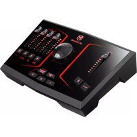
Brand : M-AUDIO
Model : DMP2
Category : Audio Preamplifier