
CPS 4.10 - Receiver ELECTRO-VOICE - Free user manual and instructions
Find the device manual for free CPS 4.10 ELECTRO-VOICE in PDF.


| Product Type | Professional Audio Receiver / Power Amplifier |
| Brand | Electro-Voice |
| Model | CPS 4.10 |
| Channels | 4 |
| Power Output (per channel) | 250W RMS @ 4 ohms, 150W RMS @ 8 ohms |
| Total Power Output | 1000W RMS |
| Frequency Response | 20 Hz - 20 kHz ±0.5 dB |
| Signal-to-Noise Ratio | >105 dB |
| THD+N | <0.05% |
| Input Impedance | 10 kΩ balanced |
| Input Connectors | 4x XLR female |
| Output Connectors | 4x SpeakON NL4, 4x binding posts |
| Cooling | Variable-speed fan, front-to-rear airflow |
| Protection Features | Short circuit, thermal, overload, DC offset, clip limiter |
| Dimensions (W x H x D) | 483 x 89 x 400 mm (19" x 3.5" x 15.75") |
| Weight | 12.5 kg (27.6 lbs) |
| Power Supply | 100-240 VAC, 50/60 Hz, 1500W max |
| Rack Mountable | Yes, 2U |
| Operating Temperature | 0°C to 40°C |
| Indicators | Power, signal, clip, protect per channel |
| Included Accessories | Power cord, rack ears, user manual |
| Recommended Use | Installed sound, live sound reinforcement, commercial audio |
Frequently Asked Questions - CPS 4.10 ELECTRO-VOICE
User questions about CPS 4.10 ELECTRO-VOICE
0 question about this device. Answer the ones you know or ask your own.
Ask a new question about this device
Download the instructions for your Receiver in PDF format for free! Find your manual CPS 4.10 - ELECTRO-VOICE and take your electronic device back in hand. On this page are published all the documents necessary for the use of your device. CPS 4.10 by ELECTRO-VOICE.
USER MANUAL CPS 4.10 ELECTRO-VOICE
Unpacking and Inspection 4
Scope of Delivery and Warranty 4
Responsibility of the User 4
Installation 6
Controls, Indicators and Connections 6
Operating Voltage 7
Mains Switch 7
Mounting 7
Ventilation 7
Selecting the Mode Of Operation (MODE) 8
Selecting the Mode of Output (OUTPUT) 10
Variable Load Drive (VLD) 11
Power on delay 12
Audio Cabeling 13
Operation 14
Volume Control 14
Indications 14
Standby Mode (POWER REMOTE) 14
Options 15
RCM-810 15
INHALT
Einführung 20
Mains Operation & Resulting Temperature 36
IMPORTANT SAFETY INSTRUCTIONS
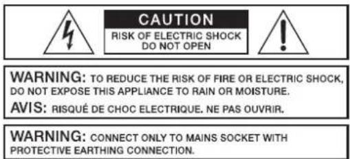
The lightning flash with arrowhead symbol, within an equilateral triangle is intended to alert the user to the presence of uninsulated „dangerous voltage“ within the product's enclosure that may be of sufficient magnitude to constitute a risk of electric shock to persons.
The exclamation point within an equilateral triangle is intended to alert the user to the presence of important operating and maintenance (servicing) instructions in the literature accompanying the appliance.
- Read these instructions.
- Keep these instructions.
- Heed all warnings.
- Follow all instructions.
- Do not use this apparatus near water.
-
Clean only with a dry cloth.
-
Do not cover any ventilation openings. Install in accordance with the manufacture's instructions.
-
Do not install near heat sources such as radiators, heat registers, stoves, or other apparatus (including amplifiers) that produce heat.
-
Do not defeat the safety purpose of the polarized or the grounding-type plug. A polarized plug has two blades with one wider than the other. A grounding type plug has two blades and a third grounding prong. The wide blade or the third prong are provided for your safety. I the provided plug does not fit into your outlet, consult an electrician for replacement of the obsolete outlet.
-
Protect the power cord from being walked on or pinched particularly at plugs, convenience receptacles, and the point where they exit from the apparatus.
-
Only use attachments/accessories specified by the manufacturer.
-
Use only with the cart, tripod, bracket, or table specified by the manufacturer, or sold with the apparatus. When a cart is used, use caution when moving the cart/apparatus combination to avoid injury from tip-over.

- Unplug this apparatus during lightning storms or when unused for a long period of time.
- Refer all servicing to qualified service personnel. Servicing is required when the apparatus has been damaged in any way, such as power-supply cord or plug is damaged, liquid has been spilled or objects have fallen into the apparatus, the apparatus has been exposed to rain or moisture, does not operate normally, or has been dropped.
- Do not expose this equipment to dripping or splashing and ensure that no objects filled with liquids, such as vases, are placed on the equipment.
- To completely disconnect this equipment from the AC Mains, disconnect the power supply cord plug from the AC receptacle.
- The mains plug of the power supply cord shall remain readily operable.
IMPORTANT SERVICE INSTRUCTIONS
CAUTION: These servicing instructions are for use by qualified personnel only. To reduce the risk of electric shock, do not perform any servicing other than that contained in the Operating Instructions unless you are qualified to do so. Refer all servicing to qualified service personnel.
- Security regulations as stated in the EN 60065 (VDE 0860 / IEC 65) and the CSA E65 - 94 have to be obeyed when servicing the appliance.
- Use of a mains separator transformer is mandatory during maintenance while the appliance is opened, needs to be operated and is connected to the mains.
- Switch off the power before retrofitting any extensions, changing the mains voltage or the output voltage.
- The minimum distance between parts carrying mains voltage and any accessible metal piece (metal enclosure), respectively between the mains poles has to be 3 mm and needs to be minded at all times. The minimum distance between parts carrying mains voltage and any switches or breakers that are not connected to the mains (secondary parts) has to be 6 mm and needs to be minded at all times.
- Replacing special components that are marked in the circuit diagram using the security symbol (Note) is only permissible when using original parts.
- Altering the circuitry without prior consent or advice is not legitimate.
- Any work security regulations that are applicable at the locations where the appliance is being serviced have to be strictly obeyed. This applies also to any regulations about the work place itself.
- All instructions concerning the handling of MOS-circuits have to be observed.
NOTE: SAFETY COMPONENT (MUST BE REPLACED BY ORIGINAL PART)

WEEE RECYCLING/DISPOSAL INSTRUCTIONS

FOR RECYCLING INFORMATION CONTACT YOUR DISTRIBUTOR OR VISIT OUR WEBSITE
WWW.EVIAUDIO.COM
The Wheelie Bin symbol found on the product or in the manual indicates that this product must not be disposed of with other waste. It is in our category the manufacturer's responsibility to properly dispose of their waste electrical and electronic equipment (WEEE) at the end of its life. Due to the differences in each EU country's management of WEEE, please contact your local distributor. We are committed to facilitate our own electronic-waste-management-system, for the free of charge return of all EVI Audio GmbH products: Telex, Dynacord, ElectroVoice, Midas Consoles, KlarkTeknik and RTS. Arrangements are made with the dealer where you purchased the equipment from, for the returning of all unusable equipment at no cost, to the factory in Straubing, for environmental protective disposal.
1 Introduction
Electro-Voice's new high efficiency CONTRACTOR PRECISION SERIES power amps combine uncompromising audio performance with the highest reliability.
1.1 Unpacking and Inspection
Carefully open the packaging and take out the power amplifier. Inspect the power amp's enclosure for damages that might have occurred during transportation. Each amplifier is examined and tested in detail before leaving the manufacturing site to ensure that it arrives in perfect condition at your place. Please inform the transport company immediately if the power amplifier shows any damage. Being the addressee, you are the only person who can claim damages in transit. Keep the cardboard box and all packaging materials for inspection by the transport company.
Keeping the cardboard box including all packing materials is also recommended, if the power amplifier shows no external damages.
CAUTION:
Do not ship the power amp in any other than its original packaging.
When shipping the power amp, make sure to always use its original box and packaging materials. Packing the power amplifier like it was packed by the manufacturer guarantees optimum protection from transport damage.
1.2 Scope of Delivery and Warranty
• 1 Power Amplifier
• 1 Owner's Manual (this document)
• 1 Mains Cord
• 1 (CPS4.5/4.10) or 2 (CPS 8.5) Output connectors, 8 pole
- 2 (CPS4.5/4.10) or 4 (CPS 8.5) Input connectors, 6 pole
• 1 Power Remote connector, 2 pole
• 1 Warranty Certificate
Keep the original invoice that states the purchase/delivery date together with the warranty certificate at a safe place.
1.3 Responsibility of the User
Speaker System Damage
CPS power amps provide extremely high power output that might be dangerous for human beings as well as for the connected speaker systems. High output voltages can damage or even destroy the connected speaker systems, especially, when the CPS amplifier is operated in bridged mode. Prior to connecting any loudspeakers, make sure to check the speaker system's specifications for continuous and peak power handling capacities. Even if amplification has been reduced through lowering the input level controls on the amplifier's front panel, it is still possible to achieve full power output with a sufficiently high input signal.
Danger at the Loudspeaker/Power Outputs
CPS amplifiers are capable of producing dangerously high voltage output that is present at the output connectors. To protect yourself from electric shock, do not touch any blank speaker cables during operation of the power amp.
WARNING:
The terminals marked with _e are hazardous live and the external wiring connected to these terminals requires installation by an instructed person or the use of ready-made leads of cords.
HF-Interference (FCC Information USA)
- IMPORTANT: Do not modify this unit! Changes or modifications not expressly approved by the manufacturer could void the user's authority, granted by the FCC, to operate the equipment.
- NOTE: This equipment has been tested and found to comply with the limits for a Class A digital device, pursuant to Part 15 of the FCC Rules. These limits are designed to provide reasonable protection against harmful interference in a residential installation. This equipment generates, uses and can radiate radio frequency energy and, if not installed and used in accordance with the instructions, may cause harmful interference to radio communications. However, there is no guarantee
that interference will not occur in a particular installation. If this equipment does cause harmful interference to radio or television reception, which can be determined by turning the equipment off and on, the user is encouraged to try to correct the interference by one or more of the following measures:
- Reorient or relocate the receiving antenna
- Increase the separation between the equipment and receiver
- Connect the equipment into an outlet on a circuit different from that to which the receiver is connected
- Consult the dealer or an experienced radio/TV technician for help
This is a Class A product. In a domestic environment this product may cause radio interferences in which case the user may be required to take adequate measures.
This Class A digital apparatus complies with Canadian ICES-003.
2.1 Controls, Indicators and Connections
Front View
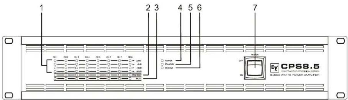
1 Level Indicators for each channel
2 Protection Indicator (PROTECT) for each channel
3 Muting Indicator (MUTE) for each channel
4 Power On/Off Indicator (POWER)
5 Standby Indicator (STANDBY)
6 Remote Amplifier Indicator (IRIS-Net)
7 Mains Switch
Rear View
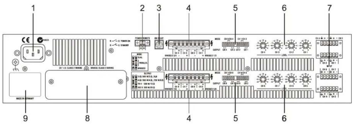
1 Mains Input
2 POWER REMOTE connector (POWER REMOTE)
3 Power On Delay selection switch (ON DELAY)
4 Power Amps Outputs (CH 1...4 / 5...8, BRIDGED)
5 Power Amp Outputs Mode Switch (MODE) and Outputs Load Switch (OUTPUT)
6 Input Level Control (LEVEL) for each channel
7 Audio Inputs (INPUT) for each channel
8 Expansion Slot (e.g. Remote Control Module RCM-810)
9 Type Plate
2.2 Operating Voltage
The power amplifier receives its power supply via the mains input. During installation, always separate the power amplifier from the mains. Connect the power amplifier only to a mains network, which corresponds to the requirements indicated on the type plate.
| Device | Voltage | Frequency | Power Consumption |
| CPS4.5 220- | 240 V AC / 120 V AC / 100 V AC 50-60 Hz 490 W | ||
| CPS4.10 220- | 240 V AC / 120 V AC / 100 V AC 50-60 Hz 840 W | ||
| CPS8.5 220- | 240 V AC / 120 V AC / 100 V AC 50-60 Hz 930 W |
Table 2.1: Operating Voltage
Mains Operation and Resulting Temperature
The power drawn from the mains network is converted into output power to feed the connected loudspeaker systems and into heat. The difference between power consumption and dispensed power is called power dissipation ( P_d ). The amount of heat resulting from power dissipation might remain inside of a rack-shelf and needs to be diverted using appropriate measures. The tables on page 36 allow the determination of power supply and cabling requirements. The tables are meant as auxiliary means for calculating temperatures inside of a rack-shelf system/cabinet and the ventilation efforts necessary.
The column P_d lists the leakage power in relation to different operational states. The column BTU/hr lists the dispensed heat amount per hour. The following factors allow direct proportional calculation of the mains current I_mains for different mains supply voltages: 100 V = 2.3, 120 V = 1.9, 220 V = 1.05, 240 V = 0.97.
2.3 Mains Switch
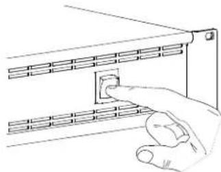
The Mains Switch on the front panel separates the power amp from the mains. Turning the Mains Switch to ON starts booting up the power amp. A soft start circuit compensates mains inrush current peaks and thus prevents the automatic cutout of the mains from reacting when switching on the power amplifier. Speaker system switch-on is delayed by approximately 4 seconds, effectively suppressing any possible power-on noise, which otherwise might be heard through the loudspeakers.
natural_image
Line drawing of a hand inserting a small component into a server rack (no text or symbols)2.4 Mounting
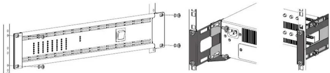
CPS amplifiers have been designed for installation in a conventional 19-inch rack case. Attach the power amp with its frontal rack mount ears using 4 screws and washers as shown in following illustration. Additionally securing the amplifier at the rear becomes necessary, if the rack case in which the power amplifier has been installed will be transported. Failure to do so may result in damage to the power amplifier as well as to the rack case. Attach the power amp as shown in the illustration using 4 case nuts and screws. RMK-15 brackets for securing the power amplifier are available as accessories.
natural_image
Technical line drawings of server rack components, showing front, side, and top views with no visible text or symbols.2.5 Ventilation
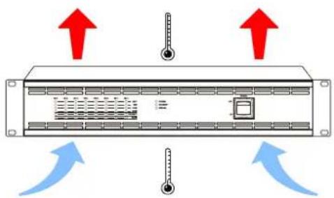
As with all Electro-Voice power amps with fan cooling, the airflow direction is front-to-rear, obviously because there is more cold air outside of the rack case than inside. The power amplifier remains cooler and dissipating the developing waste heat in a specific direction gets easier. In general, setting up or mounting the power amplifier has to be done in a way that fresh air can enter unhindered at the front and exhausted air can exit at the rear. When installing the power amp in a case or rack system, attention should be paid to these details to provide sufficient ventilation. Allow for an air duct of at least 60 mm x 330 mm between the rear panel of the power amplifier and the inner wall of the cabinet/rack case. Make sure that the duct reaches up to the cabinet's or the rack case's top ventilation louvers. Leave room of at least 100 mm above the cabinet/rack case for
ventilation. Since temperatures inside of the cabinet/rack case can easily rise up to 40 °C during operation of the power amp, it is mandatory to bear in mind the maximum allowable ambient temperature for all other appliances installed in the same cabinet/rack case.
CAUTION:
Blocking/closing the power amp's ventilation louvers is not permissible. Without sufficient cooling/ventilation, the power amplifier may automatically enter protect mode. Keep ventilation louvers free from dust to ensure unhindered airflow.
Do not use the power amplifier near heat sources, like heater blowers, stoves or any other heat radiating devices.
To ensure trouble-free operation, make certain that the maximum allowable ambient temperature of +40°C is not exceeded.
For fixed amplifier installations in a device control room that incorporates a central air-cooling system or air conditioners, calculating the maximum heat emission may be necessary. Please also take notice of the information on page 7.
Fan Cooling
The power amplifier has two fans. The fans are temperature controlled, i.e. they are not running permanently but the running speed of the fans is controlled continuously depending on the ambient temperature. That in return ensures very silent running during idle state. The temperatures of the power amp's channels are registered and monitored separately.
2.6 Selecting the Mode Of Operation (MODE)
The MODE switch on the power amp's rear panel defines how the audio inputs handle the input signals. The amplifier types CPS4.5 and CPS4.10 allow the configuration of audio inputs CH 1/CH 2 or CH 3/CH 4, the amplifier type CPS8.5 additionally allows configuration of audio CH 5/CH 6 or CH 7/CH 8.
In the following description of the modes DUAL, PARALLEL or BRIDGED the generic letters A and B are used for the two audio inputs of a MODE switch (e.g. for switch CH 1/CH 2 input A corresponds to CH 1 and input B corresponds to CH 2).
DUAL
In DUAL mode, the two channels of the power amplifier work independent from each other. This mode of operation is being used for all 2-channel applications, like stereo or Bi-Amp (active) operation. Using the input level controls on the power amp's rear panel allows independently adjusting the channels' amplification.
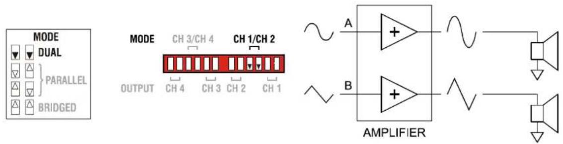
Illustration 2.1: Audio signal applied to both input connectors in DUAL mode
PARALLEL
In PARALLEL mode, the inputs of channel A and channel B are directly electrically linked. The audio signal has to be applied to the input connectors of channel A. Using the input level controls to independently control the amplification of the two channels is still possible because only the channels' inputs are linked. PARALLEL operation is the mode of choice, whenever the same input signal drives multiple power amp channels of a large system installation, e.g. when driving massive bass arrays.
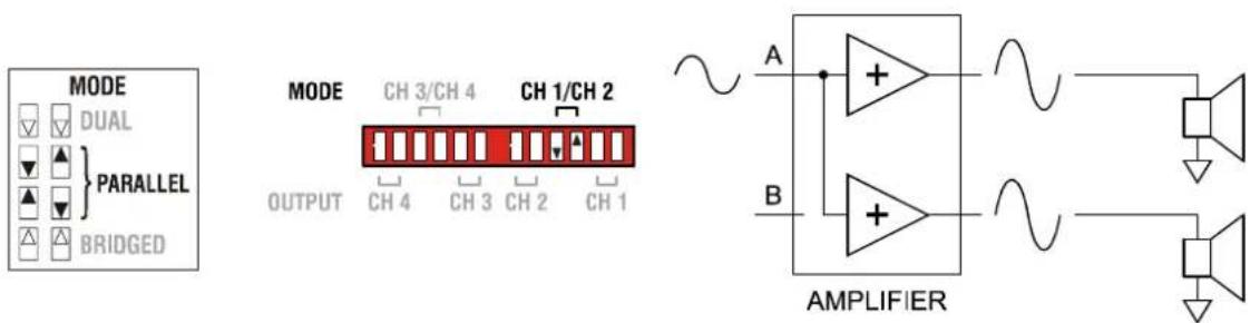
Illustration 2.2: Audio signal applied to input A connector in PARALLEL mode
CAUTION:
In PARALLEL mode, the input signal has to be fed to input channel A only.
BRIDGED
In BRIDGED mode both amp channels work in push-pull operation to provide doubled output voltage. The audio signal has to be applied to the input connectors of channel A, amplification is set via input level control of channel A only. BRIDGED operation is the mode of choice, whenever high power speakers are used.
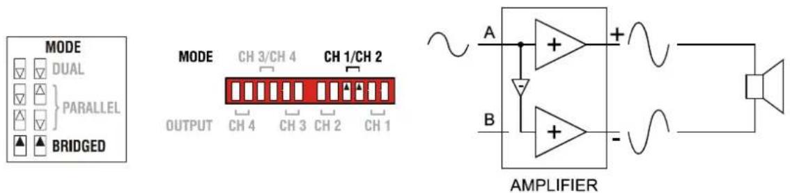
Illustration 2.3: Audio signal applied to input A connector in BRIDGED mode
CAUTION:
In BRIDGED mode operation, it is not allowable for the load connected to fall below a value of 4 ohms. Extremely high voltages can be present at the output. The connected speaker systems must be able to handle such voltages. Make sure to completely read and fully observe power rating specifications of the speaker systems to be used and to check them against the output power capacity of the power amp.
| OUTPUT 2 Ω 4 Ω 70 V 100 V | ||||
| CPS 4.5 | 4 Ω | 8 Ω | 1000 W at 140 V (≈20 Ω) | 1000 W at 200 V (≈40 Ω) |
| CPS 4.10 | 4 Ω | 8 Ω | 2000 W at 140 V (≈10 Ω) | 2000 W at 200 V (≈20 Ω) |
| CPS 8.5 | 4 Ω | 8 Ω | 1000 W at 140 V (≈20 Ω) | 1000 W at 200 V (≈40 Ω) |
Table 2.2: Minimum load in BRIDGED mode
2.7 Selecting the Mode of Output (OUTPUT)
Different output modes are available for the amplifier's output channels. Each channel can be switched to high impedance mode (HZ) for driving 70 V or 100 V loudspeakers without output transformers (Direct Drive).
In DUAL or PARALLEL mode each output channel's OUTPUT setting can be independently set. In BRIDGED mode for each pair of outputs only the OUTPUT setting of the channel with odd number (1, 3, 5 or 7) matters, the OUTPUT setting of the channel with even number (2, 4, 6 or 8) is ignored.
Following section describes the four different OUTPUT settings of CPS amplifiers.
2 Ohm Mode / VLD Mode
In 2 Ohm mode the power amplifier reaches maximum output power having a load of 2 connected. Up to 4 cabinets having a nominal impedance of 8 each can be driven by each amplifier channel. This mode should be used if a high number of speaker with medium or low power rating should be driven in low impedance mode (LZ). The VLD mode (Remote Control Module required) allows adjusting the output power of the amplifier channel. Please see page 11 for details about VLD mode.
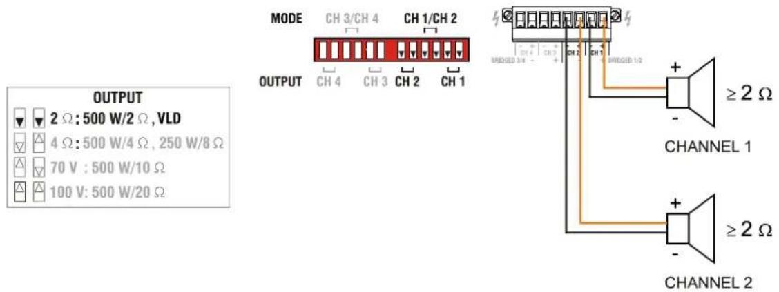
Illustration 2.4: DUAL mode of CH 1 and CH 2 in 2 Ohm Mode
4 Ohm Mode
In 4 Ohm mode the power amplifier reaches maximum output power having a load of 4 connected. Up to 2 cabinets having a impedance of 8 each can be driven by each amplifier channel. This mode should be used if speakers with high power rating (e.g. Subwoofers) should be driven in low impedance mode (LZ).
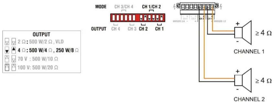
Illustration 2.5: DUAL mode of CH 1 and CH 2 in 4 Ohm Mode
70 V Mode
The 70 V mode allows connection of 70 V loudspeaker lines (Direct Drive) in high impedance mode (HZ) without using output transformers. In this case the maximum number of loudspeakers connected to an output channel is only limited by the amplifier's output power (500 W for CPS4.5/8.5 or 1000 W for CPS4.10). This mode should be used if the distance between amplifier and speaker is larger than 50 metres (approx. 150 feet) and/or a high number of small speakers (e.g. ceiling speakers) is used.
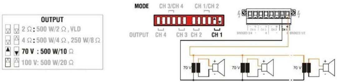
Illustration 2.6: CH 1 in 70 V mode
100 V Mode
The 100 V mode allows connection of 100 V loudspeaker lines (Direct Drive) in high impedance mode (HZ) without using output transformers. In this case the maximum number of loudspeakers connected to an output channel is only limited by the amplifier's output power (500 W for CPS4.5/8.5 or 1000 W for CPS4.10). This mode should be used if the distance between amplifier and speaker is larger than 50 metres (approx. 150 feet) and/or a high number of small speakers (e.g. ceiling speakers) is used.
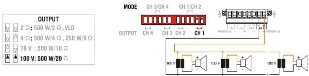
Illustration 2.7: CH 1 in 100 V mode
2.8 Variable Load Drive (VLD)
Selecting an output mode, as described in the previous chapter, provides an extremely practical way of matching amplifiers and connected loudspeaker systems. Table 2.3 shows all possible combinations of output power and connected load for power amps operated in low-impedance mode. Retrofitting an optionally available Remote Control Module (e.g. RCM-810) allows freely programming individual amplifier channels via Variable Load Drive (VLD). For power amplifier models CPS4.5 and CPS8.5 it is possible to freely select the output power in a range between 100 watts to 500 watts for loads ranging from 2 ohms to 10 ohms per channel. For the power amplifier model CPS4.10 it is possible to freely select the output power in a range between 100 watts to 1000 watts for loads ranging from 2 ohms to 10 ohms per channel. Additionally, the Remote Control Module RCM-810 allows switching a 50 Hz High-Pass filter on per channel. This may be advantageous when driving small or medium sized full-range cabinets to eliminate unwanted sub-frequency content in the audio signal.
For using VLD in a power amplifier with a Remote Control Module installed, please proceed as follows:
- Set the DIP-switch MODE (see page 8) to „2 Ω/VLD“ for power amplifier channels to be operated in VLD mode.
- Use the DIP-switch OUTPUT (see page 10) to select DUAL or PARALLEL output mode for power amplifier channels to be operated in VLD mode. VLD is not available in the BRIDGED output mode.
- Use IRIS-Net (see page 15) to configure output power, impedance and High-Pass filters of individual channels. Detailed information on the configuration, control and monitoring of amplifiers with Remote Control Modules installed can be found in the documentation that comes with the IRIS-Net software application.
The configuration of power amplifier channels is stored nonvolatile in the Remote Control Module. Please keep in mind that the VLD configuration in IRIS-Net only affects channels set to „2 Ω/VLD“ mode. Operation modes 4 ohms, 70 V and 100 V are
not affected by VLD. Power amplifier channels behave as described in chapter 2.7. The use of VLD considerably expands the adaptability of a power amplifier. Table 2.4 lists some application examples of VLD.
| 2 Ω | 4 Ω | 8 Ω | |
| 125 W | 2 Ω Mode CPSx.5 | ||
| 250 W | 2 Ω Mode CPSx.5 | 4 Ω Mode CPSx.5 or 2 Ω Mode CPS4.10 | |
| 500 W | 2 Ω Mode CPSx.5 | 4 Ω Mode CPSx.5 or 2 Ω Mode CPS4.10 | 4 Ω Mode CPS4.10 or Bridge 2 Ω CPSx.5 |
| 1000 W | 2 Ω Mode CPS4.10 | 4 Ω Mode CPS4.10 or Bridge 2 Ω CPSx.5 | Bridge 4 Ω CPSx.5 or Bridge 2 Ω CPS4.10 |
| 2000 W | Bridge 2 Ω CPS4.10 | Bridge 4 Ω CPS4.10 |
Table 2.3: Maximum Output Power (VLD deactivated)
| 2 Ω | 4 Ω | 8 Ω | |
| 125 W VLD, all types VLD, all types | 2 Ω Mode CPSx.5 or VLD CPS4.10 | ||
| 250 W VLD, all types | 2 Ω Mode CPSx.5 or VLD CPS4.10 | 4 Ω Mode CPSx.5 or 2 Ω Mode CPS4.10 | |
| 500 W | VLD CPS4.10 or 2 Ω Mode CPSx.5 | 4 Ω Mode CPSx.5 or 2 Ω Mode CPS4.10 | VLD CPSx.5 or 4 Ω Mode CPS4.10 or Bridge 2 Ω CPSx.5 |
| 1000 W | 2 Ω Mode CPS4.10 | 4 Ω Mode CPS4.10 or Bridge 2 Ω CPSx.5 | VLD CPS4.10 or Bridge 4 Ω CPSx.5 or Bridge 2 Ω CPS4.10 |
| 2000 W | Bridge 2 Ω CPS4.10 | Bridge 4 Ω CPS4.10 |
Table 2.4: Maximum Output Power (VLD activated)
2.9 Power on delay
The ON DELAY switch on the amplifier rear panel allows selection of the power on delay time. Following table shows possible switch settings and corresponding delay times in seconds.
| ON DELAY | 0 | 1 | 2 | 3 | 4 | 5 | 6 | 7 | 8 | 9 | A | B | C | D | E | F |
| Delay time | 0 | 0.15 | 0.3 | 0.45 | 0.6 | 0.75 | 0.9 | 1.05 | 1.2 | 1.35 | 1.5 | 1.65 | 1.8 | 1.95 | 2.1 | 2.25 |
CAUTION:
The setting of ON DELAY is ignored if a Remote Control Module is assembled.
2.10 Audio Cabling
Input
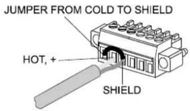
Inputs are electronically balanced. Whenever possible, using balanced audio signal feeds at the input of the power amplifier is always preferred. Unbalanced connections should only be used if the cables are very short and no interfering signals are to be expected in the vicinity of the power amplifier. In this case, bridging the screen (shielding) and the pin of the inverting input inside of the connector is mandatory. Otherwise, a 6 dB drop in level could result. Please also see following illustration. Due to their immunity against external interference sources, such as dimmers, mains connections, HF-control lines, etc., using balanced cabling and connections is always preferable.
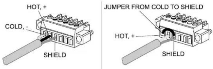
Illustration 2.8: Balanced / unbalanced connection of input
Output in DUAL Mode or PARALLEL Mode
See illustration right for connecting speakers in DUAL or PARALLEL mode. Only connection of CH 1 and CH 2 is shown, the other channels have to be connected identically.
The correct connection is also indicated at the amplifiers rear panel.
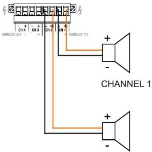
CHANNEL 2
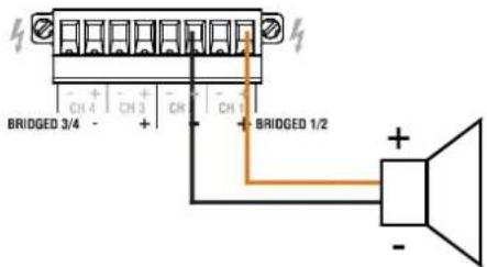
Output in BRIDGED Mode
See illustration right for connecting speakers in BRIDGED mode. Only connection at CH 1/CH 2 is shown, the other channels have to be connected identically.
The correct connection is also indicated at the amplifiers rear panel.
CAUTION:
In BRIDGED mode operation, it is not allowable for the load connected to fall below the values given in table 2.2 on page 9. Extremely high voltages can be present at the output. The connected speaker systems must be able to handle such voltages. Make sure to completely read and fully observe power rating specifications of the speaker systems to be used and to check them against the output power capacity of the power amp.
3 Operation
3.1 Volume Control
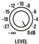
In DUAL and PARALLEL mode, the level controls LEVEL on the power amp's rear panel are used to control the amplification of the corresponding channel. Turning the control to the right increases and turning it to the left decreases the volume. In BRIDGED mode operation, the output volume for a pair of outputs is only controlled by the level control of the channel with odd number (1, 3, 5 or 7), the setting of the channel with even number (2, 4, 6 or 8) is ignored.
3.2 Indications
PROTECT
○ PROTECT
The PROTECT LED lights indicating that one of the internal protection circuits against thermal overload, short-circuit, Back-EMF, HF-occurrence at the output, etc., has been activated. In that case, the connected load is separated from the power amps to prevent the connected loudspeaker systems and the power amplifiers as well from being damaged. Whatever caused the fault – e.g. a short-circuited speaker cable – needs to be remedied. In case of thermal overload you have to wait until the power amplifier automatically regains normal operation.
MUTE
○ MUTE
The MUTE LED lights red whenever the power amp's output signal is being muted, which happens when manually muting the output signal via IRIS-Net.
-30dB...LIMIT
○ — LIMIT
○— -3dB
○—-10dB
○ - -30dB
Level indication is realized via vertical LED chains on the power amp's front panel that individually indicate the actual levels of each channel at -30dB, -10dB and -3dB below full modulation. The LIMIT LED lights as soon as the integrated dynamic audio limiter is activated and the power amplifier is driven at the clipping limit or generally at its maximum capacity. Short-term blinking is not a problem, because the internal limiter controls input levels of up to +21 dBu down to a THD of approximately 1%. If, on the other hand, the LIMIT LED light constantly, reducing the volume is recommended to prevent the loudspeaker systems connected from being damaged by probable overload.
POWER
○ POWER
The POWER LED lights green when the power amplifier is on. If the POWER LED does not light, despite the fact that the amplifier has been switched on, this indicates that the power amp is not connected to the mains or the primary fuse has blown.
STANDBY
○ STANDBY
The STANDBY LED lights yellow when the power amp is in standby mode. Standby mode reduces the amp's power consumption to an absolute minimum. Activating the standby mode is possible via IRISNet or the POWER REMOTE port at the amp's rear panel.
IRIS-Net
○ IRIS-Net
The IRIS-Net-LED lights blue if an IRIS-Net compatible remote control module has been installed in the power amp's extension slot and successful data communication has been established. The IRIS-Net LED blink slowly whenever the "Find" function in IRIS-Net is being used to locate a power amplifier in the rack.
3.3 Standby Mode (POWER REMOTE)
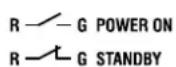
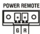
POWER REMOTE provides a simple way to remotely power-on/off the power amplifier. The POWER REMOTE function is only useful for appliances not employing a Remote Control Modul. Controlling appliances with Remote Control Module installed per REMOTE CONTROL is practically pointless. Leaving the pins of POWER REMOTE socket open the appliance power is switched on. When connecting the pins the appliance enters standby mode.
4 Options
Installing one of the optionally available extension modules in the extension slot on the rear panel lets you expand the power amp's functional range. As an example, the following paragraphs describe the RCM-810 Remote Control Module. Please read and follow the instructions provided in the documentation that you have received together with each extension module.
4.1 RCM-810
System Description and Features
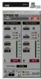
The RCM-810 Remote Control Module is a digital controller module for live sound reinforcement, PA and fixed installation applications. Installing the RCM-810 turns a conventional amp into a remote amplifier, which, at any time, provides complete overview of the overall system status and control of system parameters.
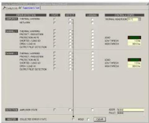
RCM-810 modules allow the integration of amplifiers into a remote control network with up to 100 devices. By using multiple networks within an IRIS-Net project up to 250 amplifiers can be used in total. This offers the possibility to control and monitor an entire PA system from one or more PCs using the IRIS-Net - Intelligent Remote & Integrated Supervision - software package. All operational states, e.g. power-on status, temperature, activation of protections, load impedance, etc., are centrally registered and displayed in IRIS-Net. This provides the possibility to react and to selectively intervene even before critical operational states arise. Programming an automatic reaction, when specific thresholds are being exceeded or fallen below, is also possible.
Parameters, like power on/off, muting, etc. can be controlled in real-time and stored in the amplifier. In the event of network failure or loss of power, all settings stay intact, independent of the control by the network.
Furthermore, the RCM-810 provides a control port with freely programmable control inputs and control outputs. Control inputs (GPI's) allow the connection of switches. IRIS-Net offers the possibility to program a variety of logic functions for the inputs. Control outputs (GPO's) allow the connection of external components, which, for example, are used to signal specific states to peripheral equipment. Consequently, an amplifier with a RCM-810 module installed corresponds to highest safety requirements. For further details about configuration, control and monitoring of amps with installed RCM-810 modules, please refer to the documentation of IRIS-Net. The latest version of IRIS-Net is available at www.electrovoice.com.
Controls and Connections
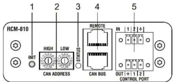
Illustration 4.1: Controls and Connections of the RCM-810
1 INIT button
INIT
O
The INIT button allows resetting the RCM-810 to factory settings. Press the button for at least 3 seconds using e.g. a small screwdriver. Table 4.1 lists the factory settings of the RCM-810 module.
CAUTION:
All RCM-810 parameters configured via IRIS-Net are discarded when pressing the INIT button.
| Parameter Value | |
| CAN-Bus data rate 10 kbit/s | |
| Power-On-Delay 0 ms | |
| Amplifier & Channel Labels RCM-810 Module, RCM-810 Input, RCM-810 Output | |
| Supervision not configured | |
| Control Ports and Job Numbers not configured | |
| VLD deactivated | |
Table 4.1: Factory Settings of RCM-810
2 CAN ADDRESS Selector Switch
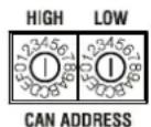
The two address selector switches are for setting the network address of the RCM-810. CAN networks support addresses in the range of 01 to 250 (FA hex). Addressing has to be carried out in the hexadecimal number system. The LOW selector switch sets the lower digit, while HIGH sets the higher digit.
CAUTION:
Each address may exist only once in a system. Otherwise, network conflicts may arise.
| HIGH | LOW | Address |
| 0 | 0 | Stand-alone |
| 0 | 1...F | 1...15 |
| 1 | 0...F | 16...31 |
| 2 | 0...F | 32...47 |
| 3 | 0...F | 48...63 |
| 4 | 0...F | 64...79 |
| 5 | 0...F | 80...95 |
| 6 | 0...F | 96...111 |
| 7 | 0...F | 112...127 |
| HIGH | LOW | Address |
| 8 | 0...F | 128...143 |
| 9 | 0...F | 144...159 |
| A | 0...F | 160...175 |
| B | 0...F | 176...191 |
| C | 0...F | 192...207 |
| D | 0...F | 208...223 |
| E | 0...F | 224...239 |
| F | 0...A | 240...250 |
| F | B...F | reserved |
Table 4.2: CAN addresses
Address 0 (00 hex, delivery status) disables remote communication between the RCM-810 and the bus. The module does not appear in the system, even though it is physically connected to the CAN-bus.
3 STATUS LED
○ STATUS
The STATUS LED is for monitoring the communication on the CAN bus. The LED blinks rhythmically every 3 seconds, when the module's address is set to "00", which means that it is disconnected from the CAN bus and software control. The LED blinks rhythmically in intervals of one second, when an address in the range of 01 to 250 has been assigned to the module and there has not yet been any activity on the CAN bus. As soon as communication on the CAN bus is recognized, the LED lights for at least 100 ms, when the power amplifier sends data on the CAN bus.
4 REMOTE CAN BUS Connection
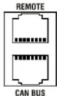
The RCM-810 module provides two RJ-45 sockets for connecting to the REMOTE CAN BUS. These sockets are connected in parallel and serve as inputs as well as for daisy-chaining the devices on the remote network. Cabling in a rack system can be established using commercially available RJ-45 network cables. However, CAN guidelines have to be observed for longer cable lengths. Both ends of the CAN bus must be terminated using 120 Ω terminating plugs.
The CAN bus allows using different data rates, whereas the data rate is inversely proportional to the bus length. For smaller network setups, data rates can be as high as 500 kbit/s. For broader networks, reducing the data rate becomes necessary (down to the minimum data rate of 10 kbit/s).
NOTE:
The data rate of the CAN bus is preset to 10 kbit/s.
The following table illustrates the relation between data rate and bus length or network size. The use of CAN repeaters is strongly recommended for busses that exceed 1000 meters in length.
| Transfer rate (in kbit/s) | Bus length (in m) |
| 500 100 | |
| 250 250 | |
| 125 500 | |
| 62,5 1000 | |
| 20 2500 | |
| 10 5000 |
Table 4.3: Transfer rate and bus length
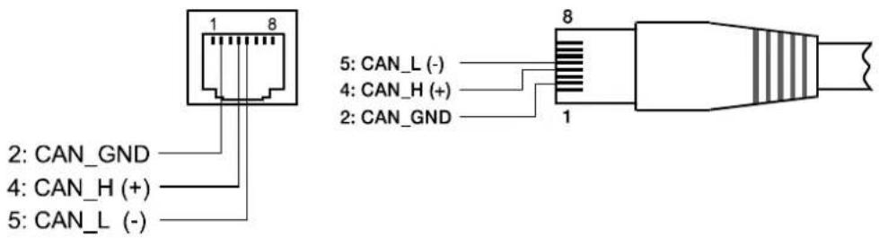
Illustration 4.2: Pin-assignment of CAN jack and CAN plug
5 CONTROL PORT
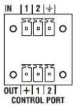
The CONTROL PORT of the RCM-810 provides two control inputs, two control outputs and reference connections for +5V and ground. The control inputs are configurable via IRIS-Net. They can be used for example for switching between power on / standby modes. The two control contacts IN 1 and IN 2 are internally connected via pull-up resistors and carry +5V (open). The control inputs can be activated using external switches, pushbuttons or relays to connect them to ground potential. The two control outputs OUT 1 and OUT 2 are open collector outputs, which are highly resistive in the non-active state (off). In active state (on) the outputs are connected to ground. The control outputs are configurable via IRIS-Net and are used to signal internal states. LEDs, indicators or relays can be driven directly. The +5V reference connector provides voltage supply for connected components.
CAUTION:
The maximally allowable current at the +5V output is 200 mA.
INHALT
Einführung 20
Mains Operation & Resulting Temperature 36
natural_image
Line drawing of a hand pressing a button on a computer drive panel (no text or symbols)2.4 Einbau
natural_image
Technical line drawings of server rack and internal components (no text or symbols)ACHTUNG:
| 2 Ω | 4 Ω | 8 Ω | |
| 125 W | 2 Ω Mode CPSx.5 | ||
| 250 W | 2 Ω Mode CPSx.5 | 4 Ω Mode CPSx.5oder2 Ω Mode CPS4.10 | |
| 500 W | 2 Ω Mode CPSx.5 | 4 Ω Mode CPSx.5 oder2 Ω Mode CPS4.10 | 4 Ω Mode CPS4.10 oderBridge 2 Ω CPSx.5 |
| 1000 W | 2 Ω Mode CPS4.10 | 4 Ω Mode CPS4.10 oderBridge 2 Ω CPSx.5 | Bridge 4 Ω CPSx.5 oderBridge 2 Ω CPS4.10 |
| 2000 W | Bridge 2 Ω CPS4.10 | Bridge 4 Ω CPS4.10 |
Amplifier at rated conditions, all channels driven, rated loads, unless otherwise specified.
| Load Impedance | Low Impedance Mode High Impedance Mode | ||||
| 2^1 | 4^2 | 8Ω | 70 V/10 ^3 | 100 V/20 ^4 | |
| Maximum Midband Output PowerTHD = 1%, 1 kHz, 4 channels driven | 500 W ^5 | 500 W | 250 WVLD: 500 W | 500 W 500 W | |
| Rated Output PowerTHD < 0.3%, 20 Hz ^6 ...20 kHz, 4 ch. driven | 450 W 450 W | 225 WVLD: 450 W | 450 W 450 W | ||
| Maximum Bridged Output PowerTHD= 1%, 1 kHz | - | 1000 W ^1 | 1000 W | 1000 W ^7 | 1000 W ^8 |
| Maximum RMS Voltage SwingTHD = 1%, 1 kHz | 32 V 45 V | 45VVLD: 63 V | 70 V 100 V | ||
| Power BandwidthTHD = 1%, ref. 1 kHz, half power @ rated load | 10 Hz...25 kHz | 50 Hz...25 kHz | |||
| Voltage Gain, ref. 1 kHz | 32 dB | 32 dB | 32 dB | 33 dB | 36 dB |
| Input Sensitivity, rated power, 1 kHz 0.775 V | (+0.0 dBu) | 1.1 V(+3.0 dBu) | 1.1 V(+3.0 dBu) | 1.55 V(+6.0 dBu) | 1.55 V(+6.0 dBu) |
| THD at rated output power, MBW = 80 kHz, 1 kHz | < 0.05% | ||||
| IMD-SMPTE, 60 Hz, 7 kHz | < 0.05% | ||||
| DIM30, 3.15 kHz, 15 kHz | < 0.02% | ||||
| Maximum Input Level | +22 dBu (9.76 Vrms) | ||||
| Crosstalk, ref. 1 kHz, at rated output power | < -80 dB | ||||
| Frequency Response, ref. 1 kHz, 8 Ω load | 15 Hz ^6 ...30 kHz (±1 dB) | ||||
| Input Impedance, active balanced | 20 kΩ | ||||
| Damping Factor, 1 kHz, 8 Ω | >240 | ||||
| Slew Rate | 28 V/μs | ||||
| Signal to Noise Ratio Amplifier, A-weighted | 98 dB | 100 dB | 100 dB | 104 dB | 106 dB |
| Output Noise, A-weighted | < -66 dBu | < -65 dBu | < -65 dBu | < -65 dBu | < -64 dBu |
| Output Stage Topology | Class D | ||||
| Power Requirements (factory configured) | 220-240 V, 50-60 Hz or 120 V, 50-60 Hz or 100 V ^9 , 50-60 Hz | ||||
| Power Consumption, 1/8 maximum output power | 490 W | ||||
| Protection | Audio Limiters, High Temperature, DC, HF, Short Circuit, Peak Current Limiters, Inrush Current Limiters, Turn-on Delay, Mains Circuit Breaker Protection, Mains Over/Under-voltage Protection | ||||
| Cooling | Front-to-Rear, temperature controlled fans | ||||
| Ambient Temperatur Limits | +5 °C...+40 °C (40 °F...105 °F) | ||||
| Safety Class | I | ||||
| Dimensions (W x H x D), mm | 481 x 88.0 x 421 ^10 | ||||
| Weight | 11.1 kg (24.3 lbs) | ||||
| Optional:Rear-rackmount | D113223 (RMK-15) | ||||
1 Output Mode 2 Ω (500 W at 2 Ω, 250 W at 4 Ω, 125 W at 8 Ω)
2 Output Mode 4 Ω (500 W at 4 Ω, 250 W at 8 Ω)
3 Output Mode 70 V
4 Output Mode 100 V
5 Depending on the ambient temperature, the unit might reduce the output power at 2Ω load
6 50 Hz High Pass is automatically activated in 70 V / 100 V output mode
7 140 V at 20 Ω
8 200 V at 40 Ω
9 Due to the mains voltage situation in Japan the values for the maximum output power can be decreased by 15%
10 Depth of the unit without rack ears (detachable): 380 mm
CPS4.10
Amplifier at rated conditions, all channels driven, rated loads, unless otherwise specified.
| Load Impedance | Low Impedance Mode High Impedance Mode | ||||
| 2^1 | 4^2 | 8Ω | 70 V/5 ^3 | 100 V/10 ^4 | |
| Maximum Midband Output PowerTHD = 1%, 1 kHz, 4 channels driven | 1000 W ^5 | 1000 W | 500 WVLD: 1000 W | 1000 W 1000 W | |
| Rated Output PowerTHD < 0.3%, 20 Hz ^6 ...20 kHz, 4 ch. driven | 900 W 900 W | 450 WVLD: 900 W | 900 W 900 W | ||
| Maximum Bridged Output PowerTHD= 1%, 1 kHz | - | 2000 W ^1 | 2000 W | 2000 W ^7 | 2000 W ^8 |
| Maximum RMS Voltage SwingTHD = 1%, 1 kHz | 45 V 63 V | 63VVLD: 89 V | 70 V 100 V | ||
| Power BandwidthTHD = 1%, ref. 1 kHz, half power @ rated load | 10 Hz...25 kHz | 50 Hz...25 kHz | |||
| Voltage Gain, ref. 1 kHz | 32 dB | 32 dB | 32 dB | 33 dB | 36 dB |
| Input Sensitivity, rated power, 1 kHz | 1.1 V(+3.0 dBu) | 1.55 V(+6.0 dBu) | 1.55 V(+6.0 dBu) | 1.55 V(+6.0 dBu) | 1.55 V(+6.0 dBu) |
| THD at rated output power, MBW = 80 kHz, 1 kHz | < 0.05% | ||||
| IMD-SMPTE, 60 Hz, 7 kHz | < 0.05% | ||||
| DIM30, 3.15 kHz, 15 kHz | < 0.02% | ||||
| Maximum Input Level | +22 dBu (9.76 V _rms ) | ||||
| Crosstalk, ref. 1 kHz, at rated output power | < -80 dB | ||||
| Frequency Response, ref. 1 kHz, 8 Ω load | 15 Hz ^6 ...30 kHz (±1 dB) | ||||
| Input Impedance, active balanced | 20 kΩ | ||||
| Damping Factor, 1 kHz, 8 Ω | >240 | ||||
| Slew Rate | 28 V/μs | ||||
| Signal to Noise Ratio Amplifier, A-weighted | 101 dB | 103 dB | 103 dB | 104 dB | 106 dB |
| Output Noise, A-weighted | < -66 dBu | < -65 dBu | < -65 dBu | < -65 dBu | < -64 dBu |
| Output Stage Topology | Class D | ||||
| Power Requirements (factory configured) | 220-240 V, 50-60 Hz or 120 V, 50-60 Hz or 100 V ^9 , 50-60 Hz | ||||
| Power Consumption, 1/8 maximum output power | 840 W | ||||
| Protection | Audio Limiters, High Temperature, DC, HF, Short Circuit, Peak Current Limiters, Inrush Current Limiters, Turn-on Delay, Mains Circuit Breaker Protection, Mains Over/Under-voltage Protection | ||||
| Cooling | Front-to-Rear, temperature controlled fans | ||||
| Ambient Temperatur Limits | +5 °C...+40 °C (40 °F...105 °F) | ||||
| Safety Class | I | ||||
| Dimensions (W x H x D), mm | 481 x 88.0 x 421 ^10 | ||||
| Weight | 11.1 kg (24.3 lbs) | ||||
| Optional:Rear-rackmount | D113223 (RMK-15) | ||||
1) Output Mode 2 Ω (1000 W at 2 Ω, 500 W at 4 Ω, 250 W at 8 Ω)
2) Output Mode 4 Ω (1000 W at 4 Ω, 500 W at 8 Ω)
3) Output Mode 70 V
4) Output Mode 100 V
5) Depending on the ambient temperature, the unit might reduce the output power at 2Ω load
6) 50 Hz High Pass is automatically activated in 70 V / 100 V output mode
7) 140 V at 10 Ω
8) 200 V at 20 Ω
9) Due to the mains voltage situation in Japan the values for the maximum output power can be decreased by 15%
10) Depth of the unit without rack ears (detachable): 380 mm
CPS8.5
Amplifier at rated conditions, all channels driven, rated loads, unless otherwise specified.
| Load Impedance | Low Impedance Mode High Impedance Mode | ||||
| 2^1 | 4^2 | 8Ω | 70 V/10 ^3 | 100 V/20 ^4 | |
| Maximum Midband Output PowerTHD = 1%, 1 kHz, 4 channels driven | 500 W ^5 | 500 W | 250 WVLD: 500 W | 500 W 500 | W |
| Rated Output PowerTHD < 0.3%, 20 Hz ^6 ...20 kHz, 8 ch. driven | 450 W 450 W | 225 WVLD: 450 W | 450 W 450 | W | |
| Maximum Bridged Output PowerTHD= 1%, 1 kHz | - | 1000 W ^1 | 1000 W | 1000 W ^7 | 1000 W ^8 |
| Maximum RMS Voltage SwingTHD = 1%, 1 kHz | 32 V 45 V | 45VVLD: 63 V | 70 V 100 V | ||
| Power BandwidthTHD = 1%, ref. 1 kHz, half power @ rated load | 10 Hz...25 kHz | 50 Hz...25 kHz | |||
| Voltage Gain, ref. 1 kHz | 32 dB | 32 dB | 32 dB | 33 dB | 36 dB |
| Input Sensitivity, rated power, 1 kHz 0.775 V | (+0.0 dBu) | 1.1 V(+3.0 dBu) | 1.1 V(+3.0 dBu) | 1.55 V(+6.0 dBu) | 1.55 V(+6.0 dBu) |
| THD at rated output power, MBW = 80 kHz, 1 kHz | < 0.05% | ||||
| IMD-SMPTE, 60 Hz, 7 kHz | < 0.05% | ||||
| DIM30, 3.15 kHz, 15 kHz | < 0.02% | ||||
| Maximum Input Level | +22 dBu (9.76 V _rms ) | ||||
| Crosstalk, ref. 1 kHz, at rated output power | < -80 dB | ||||
| Frequency Response, ref. 1 kHz, 8 Ω load | 15 Hz ^6 ...30 kHz (±1 dB) | ||||
| Input Impedance, active balanced | 20 kΩ | ||||
| Damping Factor, 1 kHz, 8 Ω | >240 | ||||
| Slew Rate | 28 V/μs | ||||
| Signal to Noise Ratio Amplifier, A-weighted | 98 dB | 100 dB | 100 dB | 104 dB | 106 dB |
| Output Noise, A-weighted | < -66 dBu | < -65 dBu | < -65 dBu | < -65 dBu | < -64 dBu |
| Output Stage Topology | Class D | ||||
| Power Requirements (factory configured) | 220-240 V, 50-60 Hz or 120 V, 50-60 Hz or 100 V ^9 , 50-60 Hz | ||||
| Power Consumption, 1/8 maximum output power | 930 W | ||||
| Protection | Audio Limiters, High Temperature, DC, HF, Short Circuit, Peak Current Limiters, Inrush Current Limiters, Turn-on Delay, Mains Circuit Breaker Protection, Mains Over/Under-voltage Protection | ||||
| Cooling | Front-to-Rear, temperature controlled fans | ||||
| Ambient Temperatur Limits | +5 °C...+40 °C (40 °F...105 °F) | ||||
| Safety Class | I | ||||
| Dimensions (W x H x D), mm | 481 x 88.0 x 421 ^10 | ||||
| Weight | 13.9 kg (28.7 lbs) | ||||
| Optional:Rear-rackmount | D113223 (RMK-15) | ||||
1) Output Mode 2 Ω (500 W at 2 Ω, 250 W at 4 Ω, 125 W at 8 Ω)
2) Output Mode 4 Ω (500 W at 4 Ω, 250 W at 8 Ω)
3) Output Mode 70 V
4) Output Mode 100 V
5) Depending on the ambient temperature, the unit might reduce the output power at 2Ω load
6) 50 Hz High Pass is automatically activated in 70 V / 100 V output mode
7) 140 V at 20 Ω
8) 200 V at 40 Ω
9) Due to the mains voltage situation in Japan the values for the maximum output power can be decreased by 15%
10) Depth of the unit without rack ears (detachable): 380 mm
5.1 Mains Operation & Resulting Temperature
| CPS4.5 Output | Mode | U_mains in V | I_mains in A | P_mains in W | P_out in W | P_d in W^4 | BTU/hr3 |
| Idle all 230 1.1 120 0 120 409 | |||||||
| 1/8 Max. Output Power @ 2 Ω2 | 2 Ω 230 | 3.7 490 4x6 | 3 238 812 | ||||
| 1/8 Max. Output Power @ 4 Ω2 | 4 Ω 230 | 3.4 465 4x6 | 3 213 727 | ||||
| 1/8 Max. Output Power @ 70 V / 100 V2 | 70 V / 100 V 2 | 30 3.3 430 | 4x63 178 6 | 07 | |||
| 1/3 Max. Output Power @ 2 Ω2 | 2 Ω 230 | 6.4 955 4x1 | 67 327 11 | 16 | |||
| 1/3 Max. Output Power @ 4 Ω2 | 4 Ω 230 | 6.3 925 4x1 | 67 257 877 | ||||
| 1/3 Max. Output Power @ 70 V / 100 V2 | 70 V / 100 V 2 | 30 6.1 870 | 4x167 202 | 689 | |||
| Normal Mode (-10dB) @ 2 Ω1 | 2 Ω 230 | 3.0 395 4x4 | 5 215 734 | ||||
| Normal Mode (-10dB) @ 4 Ω1 | 4 Ω 230 | 2.7 350 4x4 | 5 170 580 | ||||
| Normal Mode (-10dB) @ 70 V / 100 V1 | 70 V / 100 V 2 | 30 2.4 300 | 4x45 120 4 | 09 | |||
| Alert (Alarm) Mode (-3dB) @ 2 Ω1 | 2 Ω | 230 | 9.0 | 1370 | 4x225 | 470 | 1604 |
| Alert (Alarm) Mode (-3dB) @ 4 Ω1 | 4 Ω | 230 | 8.4 | 1280 | 4x225 | 380 | 1297 |
| Alert (Alarm) Mode (-3dB) @ 70 V / 100 V1 | 70 V / 100 V 2 | 30 7.6 | 1140 | 4x225 240 | 819 |
| CPS4.10 | Output Mode | Umains in V | Imains in A | P mains in W | Pout in W | Pd in W^4 | BTU/hr3 |
| Idle all 230 1.1 120 0 120 409 | |||||||
| 1/8 Max. Output Power @ 2 Ω2 | 2 Ω 230 | 5.9 840 4x1 | 25 340 1160 | ||||
| 1/8 Max. Output Power @ 4 Ω2 | 4 Ω 230 | 5.5 765 4x1 | 25 265 | 904 | |||
| 1/8 Max. Output Power @ 70 V / 100 V2 | 70 V / 100 V 2 | 30 5.3 740 | 4x125 240 | 819 | |||
| 1/3 Max. Output Power @ 2 Ω2 | 2 Ω | 230 | 12.0 | 1850 | 4x333 | 518 | 1767 |
| 1/3 Max. Output Power @ 4 Ω2 | 4 Ω 230 | 11.4 | 1760 4x33 | 3 428 1460 | |||
| 1/3 Max. Output Power @ 70 V / 100 V2 | 70 V / 100 V 2 | 30 11.1 | 1690 4x333 | 333 358 1222 | |||
| Normal Mode (-10dB) @ 2 Ω1 | 2 Ω 230 | 4.5 620 4x9 | 0 260 | 887 | |||
| Normal Mode (-10dB) @ 4 Ω1 | 4 Ω 230 | 4.2 570 4x9 | 0 210 | 717 | |||
| Normal Mode (-10dB) @ 70 V / 100 V1 | 70 V / 100 V 2 | 30 4.1 560 | 4x90 200 | 682 | |||
| Alert (Alarm) Mode (-3dB) @ 2 Ω1 | 2 Ω | 230 | 16.4 | 2730 | 4x450 | 930 | 3173 |
| Alert (Alarm) Mode (-3dB) @ 4 Ω1 | 4 Ω | 230 | 14.8 | 2390 | 4x450 | 590 | 2013 |
| Alert (Alarm) Mode (-3dB) @ 70 V / 100 V1 | 70 V / 100 V 2 | 30 14.4 | 2320 4x450 5 | 20 1774 | |||
| CPS8.5 Output | Mode | U_mains in V | I_mains in A | P_mains in W | P_out in W | P_d in W^4 | BTU/hr3 |
| Idle all 230 1.9 230 0 230 785 | |||||||
| 1/8 Max. Output Power @ 2 Ω2 | 2 Ω 230 | 6.5 930 8x6 | 3 426 1454 | ||||
| 1/8 Max. Output Power @ 4 Ω2 | 4 Ω 230 | 6.0 860 8x6 | 3 356 1215 | ||||
| 1/8 Max. Output Power @ 70 V / 100 V2 | 70 V / 100 V 2 | 30 5.6 800 | 8x63 296 10 | 10 | |||
| 1/3 Max. Output Power @ 2 Ω2 | 2 Ω 230 | 12.8 2045 | 8x167 709 | 2419 | |||
| 1/3 Max. Output Power @ 4 Ω2 | 4 Ω 230 | 12.2 1920 | 8x167 584 | 1993 | |||
| 1/3 Max. Output Power @ 70 V / 100 V2 | 70 V / 100 V 2 | 30 11.5 173 | 0 8x167 39 | 4 1344 | |||
| Normal Mode (-10dB) @ 2 Ω1 | 2 Ω 230 | 5.3 750 8x4 | 5 390 1331 | ||||
| Normal Mode (-10dB) @ 4 Ω1 | 4 Ω 230 | 5.0 700 8x4 | 5 340 1160 | ||||
| Normal Mode (-10dB) @ 70 V / 100 V1 | 70 V / 100 V 2 | 30 4.5 615 | 8x45 255 | 870 | |||
| Alert (Alarm) Mode (-3dB) @ 2 Ω1 | 2 Ω 230 | 17.0 2800 | 8x225 760 | 2593 | |||
| Alert (Alarm) Mode (-3dB) @ 4 Ω1 | 4 Ω 230 | 16.0 2600 | 8x225 560 | 1911 | |||
| Alert (Alarm) Mode (-3dB) @ 70 V / 100 V1 | 70 V / 100 V 2 | 30 14.3 230 | 0 8x225 260 | 887 |
1) Sine Modulation (1 kHz)
2) Pink Noise EN60065 / 7. Edition
3) 1 BTU = 1055.06 J = 1055.06 Ws
4) P_d = Power Dissipation
Americas Asia & Pacific Rim
Bosch Communications Systems
12000 Portland Ave South
Burnsville, MN 55337, USA
USA:
Phone:1-800-392-3497
Fax: 1-800-955-6831
Canada:
Phone: 1-866-505-5551
Fax:1-866-336-8467
Latin America:
Phone: 1-952-887-5532
Fax: 1-952-736-4212
Japan: EVI Audio Japan Ltd.
5-3-8 Funabashi, Setagaya-Ku
Tokyo, Japan 156-0055
Phone: +81 3-5316-5020
Fax: +81 3-5316-5031
China: Bosch Communications Systems
Telex EVI Audio (Shanghai) Ltd.
Room 3105-3109, No. 1 Building
No. 218, Tian Mu West Road
Shanghai, China
PC: 200070
Phone: +86 21-6317-2155
Fax: +86 21-6317-3023 Europe, Africa & Middle-E
Germany: Bosch Communications Systems
EVI Audio GmbH
Hirschberger Ring 45
D-94315 Straubing, Germany
Phone: +49 9421 706-0
Fax: +49 9421 706-265
Hong Kong: Telex EVI Audio (HK) Ltd.
Unit 5, 1/F, Topsail Plaza
11 On Shum Street
Shek Mun, Shatin, HK
Phone: +852 2351-3628
Fax: +852 2351-3329
France: EVI Audio France S.A.
Parc de Courcerin
Allée Lech Walesa
F 77185 Lognes, France
Phone: +33 1-6480-0090
Fax: +33 1-6006-5103
Singapore: Telex Pte. Ltd.
38C Jalan Pemimpin
Singapore 577180
Phone: (65) 6319 0621
Fax: (65) 6319 0620
- Installation 6
- Operation 14
- Options 15
- INHALT
- Einführung 20
- IMPORTANT SAFETY INSTRUCTIONS
- IMPORTANT SERVICE INSTRUCTIONS
- WEEE RECYCLING/DISPOSAL INSTRUCTIONS
- Introduction
- Unpacking and Inspection
- CAUTION:
- Scope of Delivery and Warranty
- Responsibility of the User
- Speaker System Damage
- Danger at the Loudspeaker/Power Outputs
- WARNING:
- HF-Interference (FCC Information USA)
- Controls, Indicators and Connections
- Operating Voltage
- Mains Operation and Resulting Temperature
- Mains Switch
- Mounting
- Ventilation
- Fan Cooling
- Selecting the Mode Of Operation (MODE)
- DUAL
- PARALLEL
- BRIDGED
- Selecting the Mode of Output (OUTPUT)
- Ohm Mode / VLD Mode
- Ohm Mode
- V Mode
- V Mode
- Variable Load Drive (VLD)
- Power on delay
- Audio Cabling
- Input
- Output in DUAL Mode or PARALLEL Mode
- Output in BRIDGED Mode
- Operation
- Volume Control
- Indications
- PROTECT
- MUTE
- -30dB...LIMIT
- POWER
- STANDBY
- IRIS-Net
- Standby Mode (POWER REMOTE)
- Options
- RCM-810
- System Description and Features
- Controls and Connections
- INIT button
- CAN ADDRESS Selector Switch
- STATUS LED
- REMOTE CAN BUS Connection
- NOTE:
- CONTROL PORT
- Einbau
- ACHTUNG:
- CPS4.10
- CPS8.5
- Americas Asia & Pacific Rim
Brand : ELECTRO-VOICE
Model : CPS 4.10
Category : Receiver