
414MKII - Cassette player TASCAM - Free user manual and instructions
Find the device manual for free 414MKII TASCAM in PDF.


| Product Type | 4-Track Cassette Multitrack Recorder/Mixer |
| Model | Tascam 414MKII (Portastudio 414 MKII) |
| Number of Tracks | 4 (simultaneous recording on 2 tracks) |
| Tape Speed | 1 7/8 ips (4.76 cm/s) |
| Wow and Flutter | ±0.15% (WRMS) |
| Frequency Response | 40 Hz – 13 kHz (standard tape) |
| Signal-to-Noise Ratio | 58 dB (with Dolby B NR) |
| Noise Reduction | Dolby B NR on playback/record |
| Inputs | 2 x 1/4" TS (Line/Mic), 2 x RCA (Line) |
| Outputs | 2 x 1/4" TS (Line Out), 1 x 1/4" TRS (Headphones) |
| Equalization | 2-band EQ (High, Low) per channel |
| Power Supply | AC 120 V / 60 Hz (US model) or 12 V DC via external adapter |
| Dimensions (W x H x D) | 16.3 x 13.8 x 4.3 inches (414 x 350 x 109 mm) |
| Weight | 11.0 lb (5.0 kg) |
| Clean Heads | Use isopropyl alcohol and lint-free swabs monthly |
| Demagnetize | Use demagnetizer after 20 hours of use |
| Safety | Do not expose to moisture; use grounded outlet |
| Repairability | Spare parts available via Tascam service centers |
| General Information | Manual in PDF available at notice-facile.com |
Frequently Asked Questions - 414MKII TASCAM
User questions about 414MKII TASCAM
0 question about this device. Answer the ones you know or ask your own.
Ask a new question about this device
Download the instructions for your Cassette player in PDF format for free! Find your manual 414MKII - TASCAM and take your electronic device back in hand. On this page are published all the documents necessary for the use of your device. 414MKII by TASCAM.
USER MANUAL 414MKII TASCAM
TEAC Professional Division
414MKII
PORTASTUDIO
3D0028100A
OWNER'S MANUAL
Safety Instructions 3
The PORTASTUDIO 414 MKII is... 4
The Recording System 5
The Three Steps to Multitrack 5
Understanding the Mixer 6-7
Signal Flow in the 414 MKII Mixer 6
Tape Cue Monitor System 7
Multitrack Cassette Recorder 8
Track Format and Tape
Recommendations 8-9
Optional Accessories 10
PORTASTUDIO 414 MKII Brief Guide 11-14
Step-By-Step Operation Guide 15-23
Let's Try the 414 MKII Mixer 15
How to Record on Track 1 16
Track 1 Playback through TAPE CUE 17
How to Make an Overdub on Track 2 18
How to Record Tracks 3 and 4 20
How to Record Many Sources onto a Single Track 20
How to Record a Mix onto Two Tracks Simultaneously 21
Recording on More than Two Tracks Simultaneously : Direct Recording 22
How to Mix Down 22
PUNCH-IN or INSERT Recording 24-25
Preliminary 24
Punch-in Procedure 25
Bouncing Tracks (Ping-Pong) 26
Ping-pong Procedure 26
Using Effects with the
PORTASTUDIO 414 MKII 27-28
Setting Effect Send Levels 27
Setting the Output Level of Effect Devices 27
Setting the Mix/Balance Control on Effect Devices 28
How to Connect Your Effects Devices 28
Syncing MIDI-Tape — Using the
TASCAM MTS-30 29
Troubleshooting
Features and Controls 31-35
414 MKII MIXER
Input Section 32
Stereo Input Section 33
Monitor Section 33
Master Section 33
Output Section 33
414 MKII RECORDER
Cassette Loading and dbx System 34
Transport Controls 34
Track Controls 35
Displays 35
Care and Maintenance 35-36
How the dbx Works 36
Specifications 37-38
Block Diagram 39-40
Level Diagram 41
"© Copyright 1999, TEAC Corporation"
All rights reserved under international and Pan American copyright conventions.
This book may not be reproduced in whole or in part, by mimeograph or any other means, without permission.
"The following marking is located on the bottom of the unit."

CAUTION
RISK OF ELECTRIC SHOCK DO NOT OPEN

CAUTION: TO REDUCE THE RISK OF ELECTRIC SHOCK, DO NOT REMOVE COVER (OR BACK). NO USER-SERVICEABLE PARTS INSIDE. REFER SERVICING TO QUALIFIED SERVICE PERSONNEL.

The lightning flash with arrowhead symbol, within equilateral triangle, is intended to alert the user to the presence of uninsulated "dangerous voltage" within the product's enclosure that may be of sufficient magnitude to constitute a risk of electric shock to person.

The exclamation point within an equilateral triangle is intended to alert the user to the presence of important operating and maintenance (servicing) instructions in the literature accompanying the appliance.
This appliance has a serial number located on the rear panel. Please record the model number and serial number and retain them for your records.
Model number Serial number
WARNING: TO PREVENT FIRE OR SHOCK HAZARD, DO NOT EXPOSE THIS APPLIANCE TO RAIN OR MOISTURE.
CAUTION:
- Read all of these Instructions.
- Save these Instructions for later use.
- Follow all Warnings and Instructions marked on the audio equipment.
1) Read Instructions — All the safety and operating instructions should be read before the product is operated.
2) Retain Instructions — The safety and operating instructions should be retained for future reference.
3) Heed Warnings — All warnings on the product and in the operating instructions should be adhered to.
4) Follow Instructions — All operating and use instructions should be followed.
5) Cleaning — Unplug this product from the wall outlet before cleaning. Do not use liquid cleaners or aerosol cleaners. Use a damp cloth for cleaning.
6) Attachments — Do not use attachments not recommended by the product manufacturer as they may cause hazards.
7) Water and Moisture — Do not use this product near water – for example, near a bath tub, wash bowl, kitchen sink, or laundry tub; in a wet basement; or near a swimming pool; and the like.
8) Accessories — Do not place this product on an unstable cart, stand, tripod, bracket, or table. The product may fall, causing serious injury to a child or adult, and serious damage to the product. Use only with a cart, stand, tripod, bracket, or table recommended by the manufacturer, or sold with the product. Any mounting of the product should follow the manufacturer's instructions, and should use a mounting accessory recommended by the manufacturer.
9) A product and cart combination should be moved with care. Quick stops, excessive force, and uneven surfaces may cause the product and cart combination to overturn.

natural_image
Symbolic icon of a person pushing a large stack of objects within a circular frame (no text or symbols)10) Ventilation — Slots and openings in the cabinet are provided for ventilation and to ensure reliable operation of the product and to protect it from overheating, and these openings must not be blocked or covered. The openings should never be blocked by placing the product on a bed, sofa, rug, or other similar surface. This product should not be placed in a built-in installation such as a bookcase or rack unless proper ventilation is provided or the manufacturer's instructions have been adhered to.
11) Power Sources — This product should be operated only from the type of power source indicated on the marking label. If you are not sure of the type of power supply to your home, consult your product dealer or local power company. For products intended to operate from battery power, or other sources, refer to the operating instructions.
12) Grounding or Polarization — This product may be equipped with a polarized alternating-current line plug (a plug having one blade wider than the other). This plug will fit into the power outlet only one way. This is a safety feature. If you are unable to insert the plug fully into the outlet, try reversing the plug. If the plug should still fail to fit, contact your electrician to replace your obsolete outlet. Do not defeat the safety purpose of the polarized plug.
13) Power-Cord Protection — Power-supply cords should be routed so that they are not likely to be walked on or pinched by items placed upon or against them, paying particular attention to cords at plugs, convenience receptacles, and the point where they exit from the product.
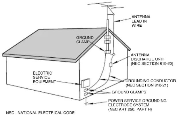
14) Outdoor Antenna Grounding — If an outside antenna or cable system is connected to the product, be sure the antenna or cable system is grounded so as to provide some protection against voltage surges and built-up static charges. Article 810 of the National Electrical Code, ANSI/NFPA 70, provides information with regard to proper grounding of the mast and supporting structure, grounding of the lead-in wire to an antenna discharge unit, size of grounding conductors, location of antenna-discharge unit, connection to grounding electrodes, and requirements for the grounding electrode.
"Note to CATV system installer:
This reminder is provided to call the CATV system installer's attention to Section 820-40 of the NEC which provides guidelines for proper grounding and, in particular, specifies that the cable ground shall be connected to the grounding system of the building, as close to the point of cable entry as practical.
Example of Antenna Grounding as per
National Electrical Code, ANSI/NFPA 70
15) Lightning — For added protection for this product during a lightning storm, or when it is left unattended and unused for long periods of time, unplug it from the wall outlet and disconnect the antenna or cable system. This will prevent damage to the product due to lightning and power-line surges.
16) Power Lines — An outside antenna system should not be located in the vicinity of overhead power lines or other electric light or power circuits, or where it can fall into such power lines or circuits. When installing an outside antenna system, extreme care should be taken to keep from touching such power lines or circuits as contact with them might be fatal.
17) Overloading — Do not overload wall outlets, extension cords, or integral convenience receptacles as this can result in risk of fire or electric shock.
18) Object and Liquid Entry — Never push objects of any kind into this product through openings as they may touch dangerous voltage points or short-out parts that could result in a fire or electric shock. Never spill liquid of any kind on the product.
19) Servicing — Do not attempt to service this product yourself as opening or removing covers may expose you to dangerous voltage or other hazards. Refer all servicing to qualified service personnel.
20) Damage Requiring Service — Unplug this product from the wall outlet and refer servicing to qualified service personnel under the following conditions:
a) when the power-supply cord or plug is damaged.
b) if liquid has been spilled, or objects have fallen into the product.
c) if the product has been exposed to rain or water.
d) if the product does not operate normally by following the operating instructions. Adjust only those controls that are covered by the operating instructions as an improper adjustment of other controls may result in damage and will often require extensive work by a qualified technician to restore the product to its normal operation.
e) if the product has been dropped or damaged in any way.
f) when the product exhibits a distinct change in performance – this indicates a need for service.
21) Replacement Parts — When replacement parts are required, be sure the service technician has used replacement parts specified by the manufacturer or have the same characteristics as the original part. Unauthorized substitutions may result in fire, electric shock, or other hazards.
22) Safety Check — Upon completion of any service or repairs to this product, ask the service technician to perform safety checks to determine that the product is in proper operating condition.
23) Wall or Ceiling Mounting — The product should be mounted to a wall or ceiling only as recommended by the manufacturer.
24) Heat — The product should be situated away from heat sources such as radiators, heat registers, stoves, or other products (including amplifiers) that produce heat.
The PORTASTUDIO 414 MKII is a 4-track "Multi-track Master" cassette tape recorder and a full-function mixer with 8 inputs/stereo outputs including a balanced microphone input and a dedicated guitar input combined into a single workstation.
Its high audio quality and creative flexibility reflect the experience and innovation that have allowed TASCAM to earn its reputation in professional audio production fields, and its user-friendly design makes the 414 MKII suitable for anyone, from expert to novice.
Using this manual : To get the most out of your 414 MKII, please take the time to read through this manual. Some time spent now will keep you from overlooking some of the features that make the 414 MKII a more creative tool. You may discover some new tricks you haven't tried before.
Use of capital letters : In general, we use all upper case type to designate a particular switch, control, jack name or label (like PAN). Transport modes and some features are described with an upper case first letter (like Record mode).
CAUTION
To power the PORTASTUDIO 414 MKII, use only the provided PS-P414 AC adaptor. Using any other adaptor will cause damage to the 414 MKII, and such damage would not be covered by the limited warranty on the product.
About the weld line
There is a patterned stripe-like effect on the bottom surface of the 414 MKII unit. This effect is called a "weld line" and is a natural result of the resin molding process employed in the manufacture of the 414 MKII unit. It is not a crack or scratch, and will cause no problems with the operation of the 414 MKII unit.
NOTE FOR U.K. CUSTOMERS
DO NOT cut off the mains plug from this equipment. If the plug fitted is not suitable for the power points in your home or the cable is too short to reach a power point, then obtain an appropriate safety approved extension lead or consult your dealer.
If nonetheless the mains plug is cut off, remove the fuse and dispose of the plug immediately, to avoid a possible shock hazard by inadvertent connection to the mains supply.
If this product is not provided with a mains plug, or one has to be fitted, then follow the instructions given below:
IMPORTANT. DO NOT make any connection to the larger terminal which is marked with the letter E or by the safety earth symbol 12 or coloured GREEN or GREEN-and-YELLOW.
The wires in the mains lead on this product are coloured in accordance with the following code:
BLUE: NEUTRAL
BROWN: LIVE
As these colours may not correspond with the coloured markings identifying the terminals in your plug proceed as follows:
The wire which is coloured BLUE must be connected to the terminal which is marked with the letter N or coloured BLACK.
The wire which is coloured BROWN must be connected to the terminal which is marked with the letter L or coloured RED.
When replacing the fuse only a correctly rated approved type should be used and be sure to re-fit the fuse cover.
IF IN DOUBT — CONSULT A COMPETENT ELECTRICIAN.
The Recording System
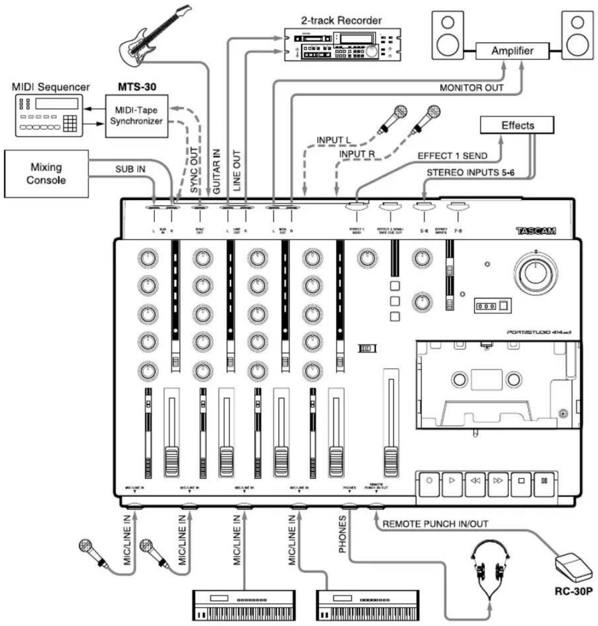
The PORTASTUDIO 414 MKII is a complete audio production facility in a single box. It is divided into two major sections: a full-function mixer and a 4-channel, multitrack cassette recorder.
To complete the recording system, you'll additionally need these: input devices (microphones, instruments), output devices (headphones), 2 track recorder, effects processors, etc.
flowchart
graph TD
    A["MIDI Sequencer"] --> B["MTS-30"]
    B --> C["2-track Recorder"]
    C --> D["Amplifier"]
    D --> E["MONITOR OUT"]
    F["Mixing Console"] --> G["SUB IN"]
    G --> H["SYNC OUT"]
    H --> I["GUITAR IN"]
    I --> J["LINE OUT"]
    J --> K["INPUT L"]
    J --> L["INPUT R"]
    K --> M["EFFECT 1 SEND"]
    L --> N["EFFECT 2 SEND/TIME OUT"]
    M --> O["STEREO INPUTS 5-6"]
    N --> P["STUDIO 414mm"]
    Q["TASCAM"] --> R["PORTASTUDIO 414mm"]
    S["RC-30P"] --> T["REMOTE PUNCH IN/OUT"]
    U["MIC/LINE IN"] --> V["MIC/LINE IN"]
    W["MIC/LINE IN"] --> X["MIC/LINE IN"]
    Y["MIC/LINE IN"] --> Z["MIC/LINE IN"]
    AA["PROCES"] --> AB["REMOPE PUNCH OUT"]
    AC["PHONES"] --> AD["REMOTE PUNCH IN/OUT"]
The Three Steps to Multitrack
In TRACKING and OVERDUBBING, the mixer inputs are usually microphones or instruments, going to different tracks of the recorder.
In OVERDUBBING, the MONITOR section and TAPE CUE of the mixer must be used to listen to
previous tracks while you record new ones, so there is a two-way flow through the console.
In MIXDOWN, signal comes from the multitrack and is sent to an external 2-track recorder.
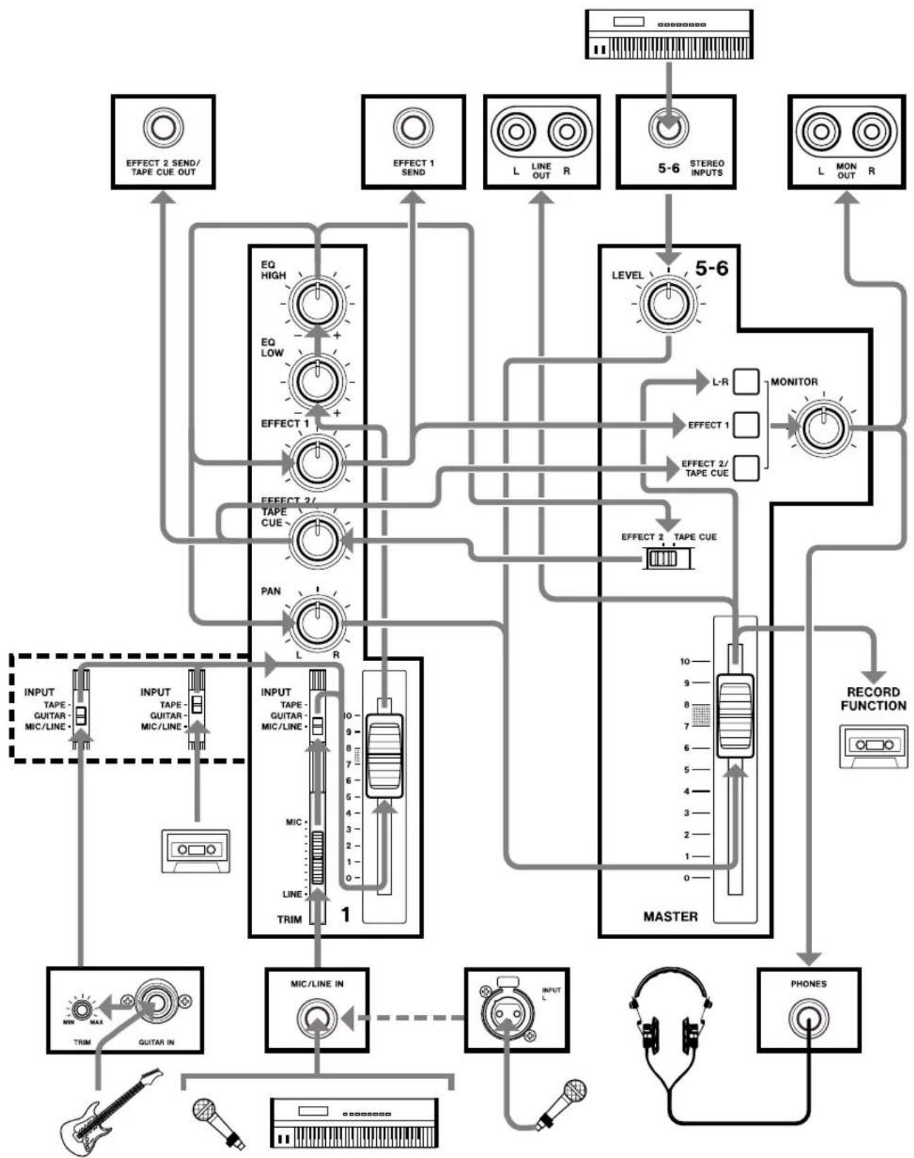
Signal Flow in the 414 MKII Mixer
The illustration below shows how input signals pass through the 414 MKII Mixer section. After the MASTER fader they go to the L/R LINE OUT jacks.
This is the most important signal route in the mixer and is called "Main Mix".
flowchart
graph TD
    A["Input TAPE-GUITAR-MIC/LINE"] --> B["TRIM"]
    C["Audio"] --> B
    D["Guitar IN"] --> B
    E["Microphone"] --> B
    F["Microphone In"] --> B
    G["Microphone"] --> B
    H["Microphone In"] --> B
    I["Microphone In"] --> B
    J["Microphone In"] --> B
    K["Microphone In"] --> B
    L["Microphone In"] --> B
    M["Microphone In"] --> B
    N["Microphone In"] --> B
    O["Microphone In"] --> B
    P["Microphone In"] --> B
    Q["Microphone In"] --> B
    R["Microphone In"] --> B
    S["Microphone In"] --> B
    T["Microphone In"] --> B
    U["Microphone In"] --> B
    V["Microphone In"] --> B
    W["Microphone In"] --> B
    X["Microphone In"] --> B
    Y["Microphone In"] --> B
    Z["Microphone In"] --> B
    AA["Microphone In"] --> B
    AB["Microphone In"] --> B
    AC["Microphone In"] --> B
    AD["Microphone In"] --> B
    AE["Microphone In"] --> B
    AF["Microphone In"] --> B
    AG["Microphone In"] --> B
    AH["Microphone In"] --> B
    AI["Microphone In"] --> B
    AJ["Microphone In"] --> B
    AK["Microphone In"] --> B
    AL["Microphone In"] --> B
    AM["Microphone In"] --> B
    AN["Microphone In"] --> B
    AO["Microphone In"] --> B
    AP["Microphone In"] --> B
    AQ["Microphone In"] --> B
    AR["Microphone In"] --> B
    AS["Microphone In"] --> B
    AT["Microphone In"] --> B
    AU["Microphone In"] --> B
    AV["Microphone In"] --> B
    AW["Microphone In"] --> B
    AX["Microphone In"] --> B
    AY["INTERCAPS/TAPE/CUE OUT"] --> AZ["EFFECT 2/TAPE/CUE"]
    BA["EFFECT 1/SALE OUT"] --> BB["EFFECT 3/SALE"]
    BC["EFFECT 1/SALE OUT"] --> BD["EFFECT 2/SALE"]
    BE["EFFECT 1/SALE OUT"] --> BF["EFFECT 3/SALE"]
    BG["EFFECT 1/SALE OUT"] --> BH["EFFECT 2/SALE"]
    BI["EFFECT 1/SALE OUT"] --> BJ["EFFECT 3/SALE"]
    BK["EFFECT 1/SALE OUT"] --> BL["EFFECT 2/SALE"]
    BM["EFFECT 1/SALE OUT"] --> BN["EFFECT 3/SALE"]
    BO["EFFECT 1/SALE OUT"] --> BP["EFFECT 2/SALE"]
    BQ["EFFECT 1/SALE OUT"] --> BR["EFFECT 3/SALE"]
    BS["EFFECT 1/SALE OUT"] --> BT["EFFECT 2/SALE"]
    BU["EFFECT 1/SALE OUT"] --> BV["EFFECT 3/SALE"]
    BW["EFFECT 1/SALE OUT"] --> BX["EFFECT 2/SALE"]
    BY["EFFECT 1/SALE OUT"] --> CA["EFFECT 3/SALE"]
    CB["EFFECT 1/SALE OUT"] --> CC["EFFECT 2/SALE"]
    CD["EFFECT 1/SALE OUT"] --> CE["EFFECT 3/SALE"]
    CF["EFFECT 1/SALE OUT"] --> CG["EFFECT 2/SALE"]
    CH["EFFECT 1/SALE OUT"] --> CI["EFFECT 3/SALE"]
    CJ["EFFECT 1/SALE OUT"] --> CK["EFFECT 2/SALE"]
    CL["EFFECT 1/SALE OUT"] --> CM["EFFECT 3/SALE"]
    CN["EFFECT 1/SALE OUT"] --> CO["EFFECT 2/SALE"]
    CP["EFFECT 1/SALE OUT"] --> CQ["EFFECT 3/SALE"]
    CR["EFFECT 1/SALE OUT"] --> CS["EFFECT 2/SALE"]
    CT["EFFECT 1/SALE OUT"] --> CU["EFFECT 3/SALE"]
    CV["EFFECT 1/SALE OUT"] --> CW["EFFECT 2/SALE"]
    CX["EFFECT 1/SALE OUT"] --> CY["EFFECT 3/SALE"]
    CZ["EFFECT 1/SALE OUT"] --> DA["EFFECT 2/SALE"]
    DB["EFFECT 1/SALE OUT"] --> DC["EFFECT 3/SALE"]
    DD["EFFECT 1/SALE OUT"] --> DP["EFFECT 2/SALE"]
    DR["EFFECT 1/SALE OUT"] --> AE["EFFECT 3/SALE"]
    AFE["EFFECT 1/SALE OUT"] --> AFE["EFFECT 2/SALE"]
    AGE["EFFECT 1/SALE OUT"] --> AH["EFFECT 3/SALE"]
    AIE["EFFECT 1/SALE OUT"] --> AJ["EFFECT 2/SALE"]
    AKI["EFFECT 1/SALE OUT"] --> AKI["EFFECT 3/SALE"]
    ALJ["EFFECT 1/SALE OUT"] --> AME["EFFECT 2/SALE"]
    ANJ["EFFECT 1/SALE OUT"] --> AO["EFFECT 3/SALE"]
    APJ["EFFECT 1/SALE OUT"] --> AQ["EFFECT 2/SALE"]
    ARJ["EFFECT 1/SALE OUT"] --> AS["EFFECT 3/SALE"]
Tape Cue Monitor System
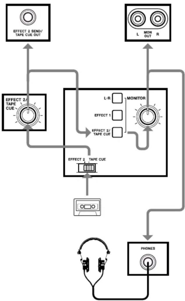
The TAPE CUE mix and MONITOR switches are also crucial for successful multitrack recording, because they control what you hear in the headphones. This CUE mix is totally independent from the Main Mix going to tape. If you don't use the CUE mix, you run the risk of accidentally "bouncing tracks" every time you record new material.
flowchart
graph TD
    A["HEADphones"] --> B["EFFECT 2/TAPE CUE"]
    B --> C["PROFESSIONAL CHECK"]
    C --> D["L-R"]
    D --> E["MONITOR"]
    E --> F["EFFECT 2/TAPE CUE"]
    F --> G["PROFESSIONAL CHECK"]
    G --> H["PHONES"]
    H --> I["OUTPUT"]
    J["EFFECT 2 SEND/TAPE CUE OUT"] --> B
    K["L MON OUT R"] --> E
The 4 TAPE CUE controls act like a separate 4x1 mixer, dedicated solely so you can hear playback from the multitrack recorder in your headphones. Settings of these controls don't affect the mix going to tape. When the "master" EFFECT 2/TAPE CUE select switch located to the right of the track 4 meter is set to the right/TAPE CUE position, the channels' TAPE CUE controls are turned to the right, the "MONITOR" EFFECT 2/TAPE CUE switch is pressed on, and the MONITOR level control is turned up, you can hear tape playback in the headphones. You can adjust the monitor level of each track by adjusting its TAPE CUE control. The channels of the Main Mix remain free to handle external inputs for recording.
If you can hear tape playback in your headphones when TAPE CUE is off, it means you're hearing tape through the Main Mix. This is correct for mixdown and bouncing tracks, but during overdubbing it can cause previous tracks to be mixed together with new tracks, instead of each part remaining separate. Use the TAPE CUE to avoid this.
The three MONITOR switches choose which mix(es) you can hear in the headphones/monitor speakers — the L-R mix, the TAPE CUE mix, and the EFFECT 1 and 2 send mixes. Press the L-R switch on to hear what you are recording.
Multitrack Cassette Recorder
The 414 MKII records on readily available standard (Philips) Compact Cassette tape, high bias Type II. The recorder has 4 tracks while the mixer has a stereo output; however, using the Direct Recording feature you can record on any or all of the 4 tracks at one time. For more details, see "Recording on More Than Two Tracks Simultaneously", page 22.
The 414 MKII's dbx Noise Reduction virtually eliminates unwanted tape noise. A special SYNC feature turns off the dbx on track 4 separately, making it possible to record and play back the MIDI sync tones or SMPTE/EBU time code without being affected by the dbx encode/decode. This ensures that the sync tones/code are recorded and played back without unnecessary processing. With proper operating techniques, it is not necessary to leave a guard band between music and sync tone tracks because of the low crosstalk of the TASCAM heads.
■ ZERO RETURN promptly brings you back to the beginning of a section of tape, selected by resetting the tape counter.
■ The tape speed can be increased or decreased with the PITCH CONTROL dial in both playback and record, to match pitch or for special effects.
Track Format and Tape Recommendations
Tape Speed and Track Format
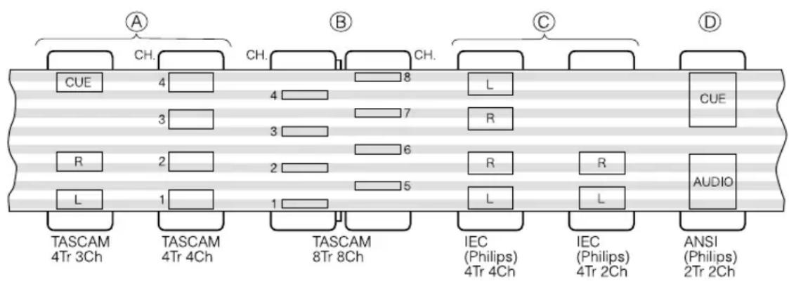
The Portastudio 414 MKII records/plays at 9.5 cm/sec (3-3/4 ips) which is twice (2 X) the normal speed of a standard audio cassette.
It also employs a discrete 4-channel format head developed especially by TEAC for TASCAM multitrack cassette recorders. Here is a comparison of various cassette formats:
Track Format and Tape Recommendations
Tape Type
The Portastudio 414 MKII is internally adjusted for HIGH BIAS Type II tape. This means that for best results, you should only use tapes of this type. TDK SA, Maxell XL-II or equivalent formulations are recommended. We strongly suggest that you select one good quality brand and use it exclusively. The time you spend creating your multitrack master is much more valuable than the money you save by buying inferior tape. The cassette shell essentially becomes a part of the 414 MKII's transport. Poor quality shells can cause wrinkles, snarls and shredding of the edges of the tape with use. Even small scratches on the tape oxide can cause "dropouts" (temporary loss of signal) on one or more tracks. High quality tapes are less likely to cause problems in the long run.
Accidental Erase/Record Protection
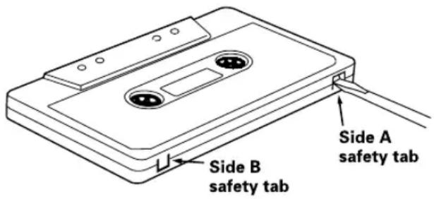
To protect a finished master tape, it is necessary to punch out both record protect tabs. Even though you are recording in only one direction, the 414 MKII uses the entire width of the tape. If, for example, you remove only one of the tabs, you could accidentally insert the cassette into the 414 MKII backwards and erase all four tracks of the master.
Tape Length
Use the shortest possible tape for a given work. It is not unusual to play a tape 100 times before you are finished, so select a cassette length that is as close as possible to the length of the program you plan to record. Cassettes C-60 length and shorter are often made from thicker stock than longer cassettes.
The tape used in C-120 cassettes is extremely thin and can cause winding problems, crimping, wrinkling, and other damage to the oxide coating of the tape which will destroy your work. Don't use C-120s in the 414 MKII.
Remember that with twice the normal speed and the "one-side-only" 4-track single direction format, you have only one quarter of the normal play time:
| Cassette Play Time | |
| C-46 11.5 min. | |
| C-60 15 min. | |
| C-90 22.5 min. |
(approx.)
Optional Accessories
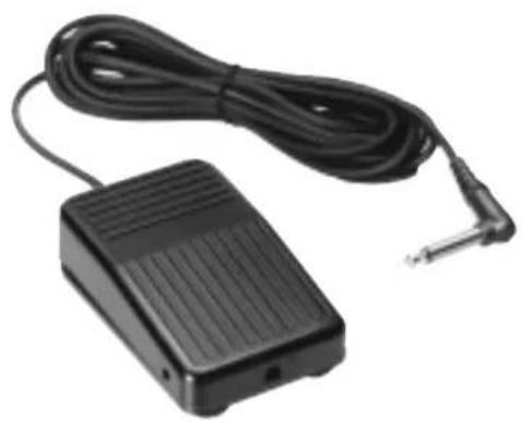
RC-30P Remote Footswitch
natural_image
Black electronic device with a coiled cable and terminal connector (no visible text or symbols)Head Demagnetizer
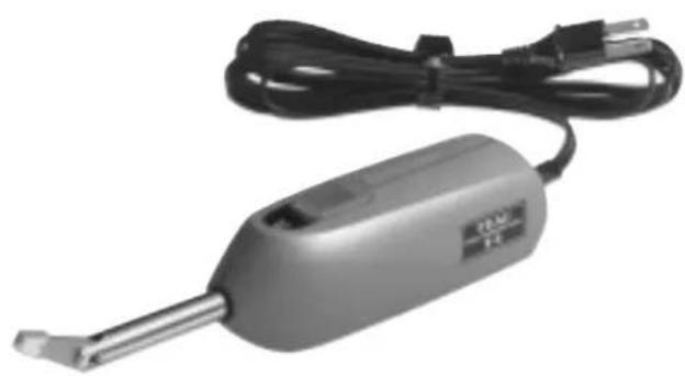
natural_image
Exterior view of a handheld electronic device with black cable and metallic tip (no visible text or symbols)TZ-261 Cleaning Kit (Except U.S.)

MIDI-Tape Synchronizer
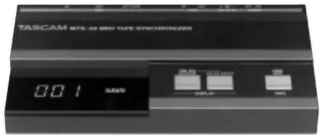
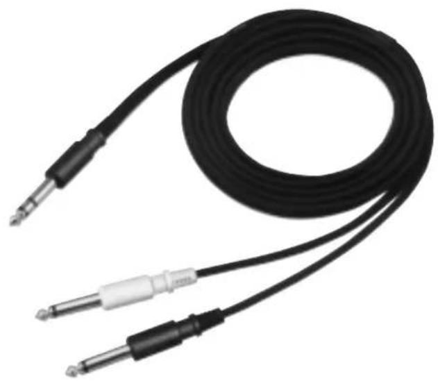
PW-2Y/PW-4Y Insertion Cable
natural_image
Coiled black audio jack with two metallic connectors (no text or symbols visible)HC-1 Head Cleaner & RC-1 Rubber Cleaner (U.S.only)


PORTASTUDIO 414 MKII Brief Guide
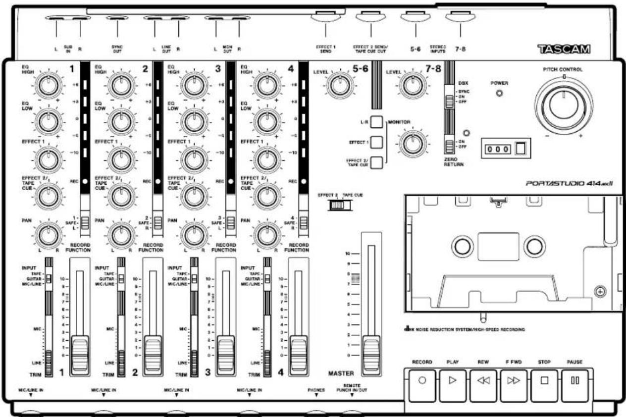
For detailed information on each feature, see "Features and Controls", pp. 31-35.
Input Selection and Adjustment
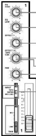
Channels 1 through 4
EQ HIGH : Cuts or boosts treble frequencies. Shelving point is at 10 kHz.
EQ LOW: Cuts or boosts bass frequencies. Shelving point is at 100 Hz.
EFFECT 1 and 2: These control how much signal will go to the corresponding EFFECT send jacks. They get their signal from a point just after the channel fader.
TAPE CUE : The EFFECT 2 controls can be switched to act as the TAPE CUE level controls (by means of the correspondingly labeled switch) and adjust the playback level for the musicians in the studio.
PAN : Sets the pan position (left-right balance) of the channel. Note that the Left Mix can be recorded on tracks 1 and 3, and the Right Mix onto tracks 2 and 4.
INPUT : Determines where the channel signal comes from.
TAPE: Makes tape playback the channel source.
GUITAR: When this is selected, makes the GUITAR input the channel source. If no instrument is plugged into the GUITAR input, this is equivalent to OFF.
MIC/LINE; Brings the MIC/LINE input into the channel.
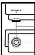
Channel fader : Sets the volume of the channel feeding the MASTER fader.
TRIM : Sets how much preamplification will be added to the MIC/LINE IN jack. Push up if the signal needs amplification, pull down if the signal is so loud it is distorting the mixer electronics.
MIC/LINE IN (on the front): These are the input jacks for the mixer channels. Line-level, unbalanced signal sources (such as electronic instruments) may be connected here. You can also connect lower-level signals (down to -50 dBV) and use the TRIM control to amplify them.
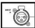
INPUT L & R : These balanced XLR-type connectors are for balanced microphones. If a signal source is connected to the front MIC/LINE IN jack corresponding to the XLR-type connector where a microphone is connected (L=1 or 3, R=2 or 4), the microphone signal input here is ignored. In other words, if you want to use microphones with these connectors, make sure that nothing is plugged into the corresponding MIC/LINE IN jack at that time.
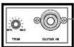
GUITAR IN jack and TRIM control : This 1/4" jack is specially designed for connection of an electric guitar (or bass guitar). This dedicated input is provided because these instruments have an impedance that is different to that of microphones or line level sources. A guitar played through this jack will be used as the signal to a channel, if the INPUT switch of the channel is set to the center GUITAR position. Use the TRIM control by this jack to match the level of your guitar.
PORTASTUDIO 414 MKII Brief Guide
Recorder Controls
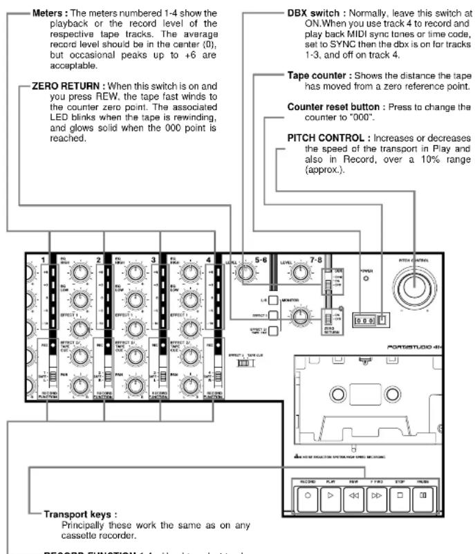
RECORD FUNCTION 1-4 : Used to select tracks to record on, and also recording sources (channels or stereo busses).
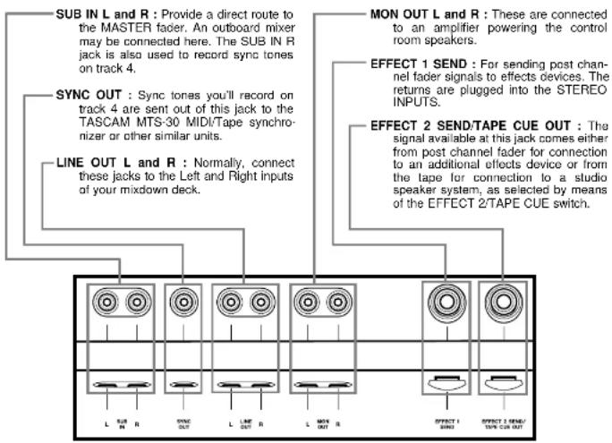
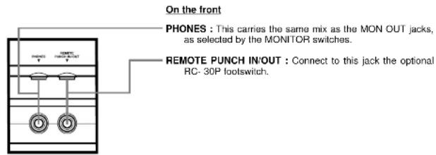
Connections on the Rear Panel
Let's Try the 414 MKII Mixer
To learn how the mixer works, we'll use a microphone as the source. If your dynamic microphone cable has a balanced XLR-type connector, we'll use the rear-panel XLR-type INPUT (L, R) connector. If it is fitted with an unbalanced 1/4" connector, we'll use the front-panel MIC/LINE IN jack.
If a signal source is connected to a front MIC/LINE IN jack whose corresponding XLR connector has a microphone connected (L=1 or 3, R=2 or 4), the signal input to the XLR connector will be ignored.
First, make the following settings :
■ Pull all the TRIM controls full down and turn other level controls all the way to the left.
■ Turn the EQ controls to their center "off" position; bring all the faders down; and set all the switches to OFF.
1 Have in hand a dynamic microphone and a set of stereo headphones.
2 Input connections
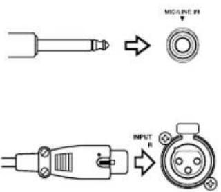
Depending on the connector at the end of your microphone cable, plug the microphone to the INPUT (L, R) connector on the rear panel, or the MIC/LINE IN jack for channel 1 on the front panel.
3 Powering on
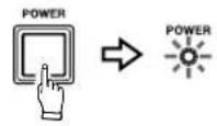
Press the POWER switch on (the switch is located on the back), and the POWER indicator on the top panel will light.
4 Headphone connection
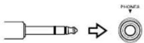
Plug your headphones into the front PHONES jack, so you can hear the input signal going to the mixer section of the 414 MKII.
5 Routing inputs
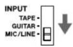
Set the channel 1 INPUT select switch to the MIC/LINE position.
6 Panning
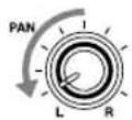
Turn the channel 1 PAN control all the way to the left.
7 Channel level
Raise the channel fader to the shaded area (between 7 and 8).
8 Master level
Raise the MASTER fader to the shaded area (between 7 and 8).
9 Monitor selection
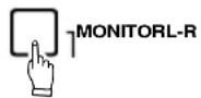
Press the MONITOR "L-R" switch on.
10 Monitor level
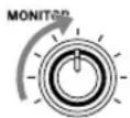
Turn the MONITOR level control up to the 12 o'clock position.
11 TRIM adjustment
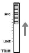
While speaking into the microphone, slowly push the TRIM control in channel 1. You will hear your voice on the left side in the headphones.
When using a line level source (such as electronic instruments) instead of a microphone, the TRIM does not need to be pushed up very far, if at all.
How to Record on Track 1
As a trial, let's record your voice on tape.
1 Have in hand a new cassette tape (Type II, C-90 length or shorter).
2 Loading a cassette
Pull the cassette door open. Insert your cassette tape. Close the door.
3 Getting past the leader tape
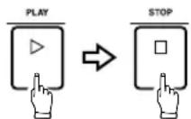
Press PLAY and allow the tape to run for about 5 seconds. This will run the tape leader onto the take-up reel, and put the beginning of the tape in front of the heads.
4 Resetting the counter
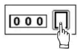
Reset the tape counter to 000 by pressing the adjacent button.
5 Selecting tracks
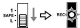
Set the RECORD FUNCTION switch for track 1 to its L position. The track's REC indicator will start blinking, indicating that the track is in Record Ready mode.
6 Mic level adjustment
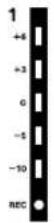
Speak into the microphone. You will see meter 1 move. Slowly push the channel 1 TRIM control until the meter peaks at no more than "+6".
7 Beginning recording
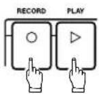
Hold RECORD and press PLAY to initiate recording. The REC indicator that was blinking will turn on solid, indicating the track is in Record mode.
8 Speak into the microphone.
9 Stopping recording
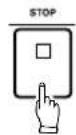
Press STOP (or PAUSE) to stop the tape and finish recording.
10 Putting track into "Safe"
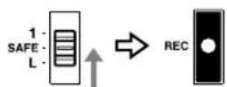
The track 1's REC indicator should now be blinking as before. Set the RECORD FUNCTION switch for track 1 to its SAFE position.
Track 1 Playback through TAPE CUE
1 Selecting TAPE CUE
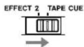
Set the EFFECT 2/TAPE CUE selection switch located to the right of the track 4 meter to the right/TAPE CUE position.
2 Monitor selection
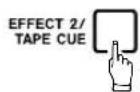
Press the lowest MONITOR switch on (the switch marked EFFECT 2/TAPE CUE). The other two MONITOR switches must be off.
3 Locating tape to zero
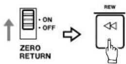
Set the ZERO RETURN switch to ON, then press REW.
4 Beginning playback
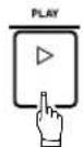
Press PLAY.
5 MONITOR level control setting
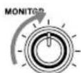
Check to see that the MONITOR level control is at the 12 o'clock position.
6 Routing tape signals to TAPE CUE
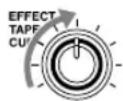
Locate the EFFECT 2/TAPE CUE level control on channel 1 and slowly turn it to the right. You'll hear, in center mono, what you have recorded on track 1.
7 Stopping playback
Press STOP to stop playing.
How to Make an Overdub on Track 2
Overdubbing entails recording one or more additional tracks on the same tape, while listening to previously recorded tracks using TAPE CUE.
Leave the microphone connected to the channel 1 input. There is no need to repatch it to channel 2 to record on track 2. You can send any mixer input to any track of the recorder through the combination use of PAN and RECORD FUNCTION.
1 Routing input
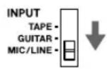
Set the channel 1 INPUT selection switch to the MIC/LINE position.
2 Panning
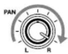
Turn the channel 1 PAN control all the way to the right (R) position.
3 Channel 1 level
Bring the channel 1 fader to the shaded area (between 7 and 8).
4 Master level
Bring the MASTER fader to the shaded area (between 7 and 8).
5 Monitor selection
Press the MONITOR select switch L-R on. (Leave the EFFECT 2/TAPE CUE switch pressed on.)
6 Locating tape to zero
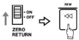
Making sure that the ZERO RETURN switch is ON, press REW and the tape will rewind to the beginning of the track 1 recording.
7 Track selection
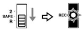
Set the RECORD FUNCTION switch for track 2 to its R position. The track's REC indicator will start blinking.
8 Record level adjustment (TRIM)
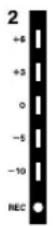
Speak into the microphone to check to see meter 2 move. Slowly push the channel 1 TRIM control until the meter peaks at no more than +6.
9 Beginning recording
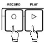
Hold RECORD and press PLAY to initiate recording. The track 2's REC indicator that was blinking will turn on solid, indicating the track is now being recorded.
10 Monitoring input/tape
You will hear track 1 play, together with the new signal going to track 2, in the headphones.
NOTE
Adjust only the TAPE CUE control of channel 1 if you need to change the balance between the old and new tracks in your headphones. Leave the channel fader and TRIM and the MASTER fader alone, because they control the level being recorded.
11 Stopping recording
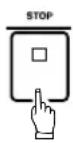
Press STOP (or PAUSE) to stop recording.
12 Putting track into "Safe"
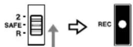
The track 2's REC indicator should now be blinking as before. Set the RECORD FUNCTION switch for track 2 back to its SAFE position and the indicator will turn off.
How to Record Tracks 3 and 4
Tracks 3 and 4 can be recorded using almost the same procedure just shown for tracks 1 and 2. Just use the applicable RECORD FUNCTION switches, and the PAN controls should be rotated to the LEFT for recording on Track 3 and to the RIGHT for Track 4.
How to Record Many Sources onto a Single Track
In the first example, we recorded one source onto one track at a time for simplicity. But the mixer of the Portastudio 414 MKII can take multiple channels and mix them onto a single track. To do this :
- Set the PAN control of each channel to the same setting, for example :
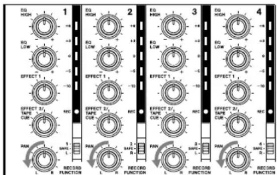
In this example, all instruments plugged into channels 1-4 will be recorded onto Track 1 or 3.
●Lower the MASTER fader to make overall level adjustments once you have each channel's TRIM and fader level set.
●Make sure the INPUT switch of every channel you want to record is set to MIC/LINE.
■ You can't record the stereo channels onto a single track.
How to Record a Mix onto Two Tracks Simultaneously
If you want to record multiple sources onto two tracks, you use the channel PAN controls to send them to LEFT or RIGHT (or anywhere in between, if you're making a stereo mix). The track RECORD FUNCTION switches choose what track the Left and Right mixes will be recorded on. Note that in this method, the mixer channel number has nothing to do with what track the instrument winds up on. Any mixer channel can be panned to any track.
These mixer channels are being sent to the LEFT, for recording on either Track 1 or Track 3.
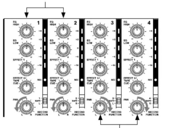
These mixer channels are being sent to the RIGHT, for recording on either Track 2 or Track 4.
■ Press the MONITOR L-R switch on.
Recording is the same procedure as for one track. In the example above, set the RECORD FUNCTION switch for track 3 to L, and the switch for track 4 to R, to record on these two tracks simultaneously.
Restrictions : The 414 MKII mixer section has only two main mixes, Left and Right. For this reason, you can record only two tracks at once while you're recording a mix of instruments (for example, two instruments on track 1, three instruments on track 2). Also, you can record a mix only on combinations or even/odd numbered tracks (1 & 2, 1 & 4, 2 & 3 etc.). If the RECORD FUNCTION switch for track 1 and that for track 3 are both set to L, the two tracks will both record the same mix.
Recording the stereo channels (5-6 and 7-8):
It is possible to record up to six sources simultaneously, using the four standard mixer channels plus the two pairs of stereo channels. The stereo channel's signal is sent to the stereo mix bus passing through the LEVEL control, so the signal is recorded along with any other channels' signals sent to the stereo left and right buses. Since there is no PAN control, the stereo channel's signal is set to the "hard left" and "hard right" position.
Recording on More than Two Tracks Simultaneously : Direct Recording
It is possible to record on three or four tracks at the same time by setting the respective RECORD FUNCTION switches to their numbered (1-4) position. In this Direct recording, each track gets its signal from a single mixer channel only — track 1 from channel 1, and so on.
■ In Direct recording, the MASTER fader has no effect on the record level. It only affects the level going to the headphones/monitor speakers (via MONITOR L-R switch). Use the CHANNEL FADER only to set record levels.
■ Even when using the direct recording capability, a channel still goes to the Left/Right mix. If you record another track with the stereo left or right mix at the same time, you must check your PAN settings. For example, you can record a vocal directly onto track 3, and record multiple instruments on track 1 via the stereo left bus at the same time. But channel 3's PAN control must be turned hard right, otherwise you'll wind up with vocals "bleeding through" onto track 1's instruments.
■ The direct recording can be used whenever you want to record a single channel to a single track.
How to Mix Down
When the 4 tracks are all recorded, the final step is mixing them into a standard stereo format. This procedure is known as Remixing or Mixing down. During this procedure the tracks are blended together and balanced to create the desired sound.
1 Connections
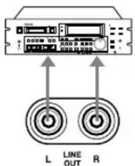
Connect the LINE OUT L jack of the 414 MKII to the left line input of the mixdown deck, and the LINE OUT R jack to the right line input.
2 Master level
Raise the MASTER fader to the shaded area between 7 and 8.
3 Monitor source
Press the MONITOR L-R switch on. All other MONITOR switches must be off.
4 Routing inputs
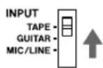
Set all the INPUT select switches on the input channels to the TAPE position.
Step-By-Step-Operation Guide
5 Playback level
Press PLAY and, while listening to the tape play, tentatively set the channel faders.
6 Adjust the PAN controls to set each track's left-to-right position for the desired stereo image. You may also want to use the EQ controls to adjust the individual tracks for the desired tonality. (For using effects, see pp. 27 & 28.)
7 Using the MASTER fader, adjust the overall playback level.
8 Review
When the signal balance, level, and tonality sound right, rewind the tape, and press PLAY again to check the result.
9 Rewind the multitrack tape again. Put a blank tape in the mixdown deck and let it play for 5 seconds, then stop it and reset the mixdown deck's counter to zero.
10 Press PLAY on the 414 MKII.
11 Record level
Put the mixdown deck into its "Record Ready" mode, and adjust its input level controls for the desired record level.
12 Rewind the multitrack tape to the beginning of the recording.
13 Put the mixdown deck into Record mode then press PLAY on the 414 MKII.
14 When recording is done, stop both machines, rewind the mixdown tape and listen to it.
If the mixdown tape does not sound right, make the necessary corrections and re-do from the beginning.
PUNCH-IN or INSERT Recording
"Punching in" or "insert recording" is recording over a small section of previously recorded track to correct or improve a performance, while keeping the rest of the track intact. The mixer settings should be exactly the same as they were during the original recording.
In the following, we'll use track 2 as the punch-in track as an example.
Preliminary
1 As the punch-in track is track 2 in our example, your input must be sent to the stereo right bus. To do so, rotate the PAN control of the channel into which your source instrument is plugged all the way to the right.
2 TAPE CUE signal path is used to hear the tape, so set the master EFFECT 2/TAPE CUE select switch to the right/TAPE CUE position and press the same labeled MONITOR switch on.
3 To hear the instrument, press the MONITOR L-R switch on.
4 Press PLAY to play the tape, adjust the TAPE CUE control on channel 2 to the desired listening level.
If you want to hear other tracks together, turn up their TAPE CUE controls as well to the desired level and balance, and adjust the overall level with the MONITOR control.
5 Play the instrument. You'll hear it together with the tape signals through the headphones. Stop the tape, and you hear only the instrument being played.
6 Set the RECORD FUNCTION switch for track 2 to R. The track's REC indicator will start blinking, and meter 2 will show your instrument's output level. Adjust the channel and MASTER faders for the proper recording level.
Selecting in and out points
For both musical and technical reasons, when punching in or out of a track, you must select points that are "in the points clear", i.e., in pauses between phrases or notes. The sound will seem unnatural and inserts will be noticeable if a new note is recorded before the old one has ended, or a note is held as you punch in or out. Making smooth inserts requires practice. Spacing between the erase and record heads requires that you anticipate in/out points by a fraction of a second for extremely tight cues.
Punch-in Procedure
There are 2 ways to initiate the punch-in recording. The first is with the transport RECORD button, and the second is with the optional footswitch.
Perform the "Preliminary" on the previous page, if you haven't yet done so.
Punching-in/out with RECORD
1 Check to see that the track 2's REC indicator is blinking showing the track is in the Rec Ready mode. Locate the tape a little behind the expected punch-in point. Then press PLAY.
2 When you reach JUST BEFORE the error, hold PLAY and push RECORD. The REC indicator that was blinking will glow solid and track 2 enters the Record mode.
3 To punch-out of record, push STOP (or PAUSE). The REC indicator that was lit solidly blinks to indicate that recording is over.
Using the remote footswitch (RC-30P)
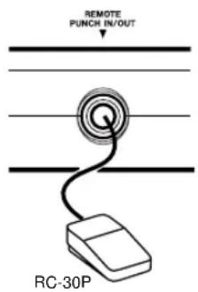
If you are recording alone and are too busy playing an instrument to push the switches, the optional remote footswitch really comes in handy.
1 Plug the RC-30P into the REMOTE PUNCH IN/OUT jack on the front of the 414 MKII.
2 Check that the track 2's REC indicator is blinking, and locate the tape to a point a little before the error, then press PLAY.
3 When you reach JUST BEFORE the error, press the footswitch, and the REC indicator that was blinking will glow steadily to indicate the track is in the Record mode.
4 To punch-out of record, press the footswitch again. The REC indicator will start blinking again.
5 To stop the tape, press STOP.
Bouncing Tracks (Ping-Pong)
The recording capability of the PORTASTUDIO 414 MKII is not limited to four tracks. You can "bounce" or combine tracks you have recorded to an empty track, and then replace the original tracks with new material. A bounce is like a mixdown, except you are recording to one of the tracks of the 414 MKII instead of to an external recorder. The following diagrams depict the process.
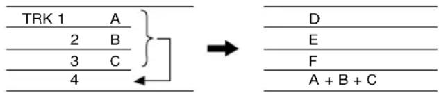
Bouncing tracks 1-3 onto track 4
Tracks 1-3
available for
recording new parts
During a bounce you can add live sources along with the prerecorded tracks, using the "empty" mixer channels not being used for tape playback. This gives you even more ways to add layers to a composition. For example, you can bounce tracks 1-3 along with another "live" part onto track 4, for a total of four parts on one track.
Ping-pong Procedure
In this example, we will combine material from tracks 1-3 onto track 4.
1 On channels 1-3, make the following settings :
- INPUT to TAPE,
- PAN all the way to R, and
- Channel fader to the shaded zone (7-8 on the scale).
2 Push the MASTER fader to the shaded zone.
3 Press the MONITOR L-R switch on. The other two MONITOR switches must be off.
4 Set the RECORD FUNCTION switch for track 4 to R. The track 4's REC indicator will start blinking, indicating the track is in Rec Ready mode.
5 Press PLAY. The tape will start playing.
6 Use channel faders 1 through 3 to make any necessary level adjustments. You may want to repeat this step several times to get the balance correct.
7 When the balance is right and the level is peaking at no more than +6 on the track 4 meter, stop and rewind the tape to the beginning of the track.
8 Hold RECORD and press PLAY. The REC indicator that was blinking will turn on solid and track 4 will record a copy of what is on tracks 1-3.
9 You'll hear the mix being recorded on track 4 in the headphones.
10 Once the recording is done, press STOP (or PAUSE).
11 The REC indicator will now be blinking as before. Turn that off by setting the RECORD FUNCTION switch for track 4 to SAFE.
Effects and signal processing are areas where you can really start to have fun customizing your sound, and develop your own unique recording style. Because there are so many possibilities, it also can be confusing. There are many different effect units on the market, all with different controls, types of inputs and outputs, and other characteristics. Read the manual of your effects device, and the following sections to get the complete story of what's possible for your particular situation.
-
In-line processing: The processing that's easiest to understand doesn't involve the 414 MKII directly at all. You can plug your instrument directly into the input of the effect device, and plug the output of the device directly into a line input of the 414 MKII. The whole signal gets processed (flanged, doubled, limited, delayed etc.), and only one instrument can use that processor. Effect pedals for guitar are typically used this way. To get a mix of processed ("wet") and original ("dry") signal, the unit must have its own MIX or BALANCE control.
-
Send/return mix processing: This is the most common method of effect processing, especially for reverb and delay. It allows a number of different channels to use the same effect, while allowing you to control how much effect is mixed with each channel. Each of the 4 mixer channels can send signals to the EFFECT SEND 1 or 2 outputs. These outputs can then be connected to the input of effects devices. The processed signals from the devices are plugged into the stereo channels (5-6 and 7-8), for them to be mixed onto the stereo left and right buses. The whole path—from the EFFECT SENDS to the reverb and back into STEREO INPUTS—is called an “effects loop”. The EFFECT 1 and 2 controls determine how much signal goes to the reverb unit; the LEVEL control on the stereo channels determines how much returns from the reverb unit. In this method the stereo inputs function as effects returns.
Setting Effect Send Levels
The goal is not to distort the device, while staying above the noise that effect units generate. To get the best signal-to-noise from most effects units, you should send it as strong a signal as you can. With a properly set input signal in the 414 MKII, the channel EFFECT send set to about 2 o'clock position (for EFFECT 1 or EFFECT 2 feed), you should get a fairly loud signal from the EFFECT SEND jacks.
If your effects device has an input level control of its own, it should be set so the meter or signal light of the effects device is just under the overload point on peak signals. When you want to hear less effect overall, turn down the return LEVEL control on the stereo channels.
Setting the Output Level of Effect Devices
If the effect send level has been set properly, in most cases the output level of the effect unit should be set as high as possible without clipping (distorting) the STEREO INPUTS of the 414 MKII, but low enough so that you have a reasonable range of control. If you can get the effect sound you want with the return LEVEL control in the 12 to 2 o'clock range, you're in the ballpark. If, on the other hand, very small settings of the Effects Return still give you a mix drowning in effects, turn down the output level of your effect device.
Some effect units have rear panel switches setting input and output level ranges between "+4" and "-20 dB". In this case, try setting the input to -20 (high sensitivity) and the output to +4 (full output level).
Setting the Mix/Balance Control on Effect Devices
When it's being used in a send-return mix, set the mix/balance of your effect device all the way to "wet" or full processing with no direct original signal. In send/receive processing, the dry signal goes down the 414 MKII's channel fader to be mixed with the effect return signal on the stereo mix. Therefore, you don't need any "dry" signal coming to the effects return. The mix/balance control is set toward "dry" only when you're using the effects device as an in-line processor.
How to Connect Your Effects Devices
There is no absolute "right" or "wrong" way to do this—there are several ways, each with its own consequences. The diagram shows the most common method. EFFECT SEND feeds a reverb unit, which has a synthesized stereo output patched into STEREO INPUTS 7-8. A special "stereo splitter" cable (such as the optional PW-2Y/4Y) is used, with the 3-conductor (Tip-Ring-Sleeve) end plugged into channel 7-8, and the other end split to two 2-conductor plugs connected to the Left and Right outputs of the effects unit. If the return is connected to channel 5-6 and nothing is connected to channel 7-8, turn the 7-8 LEVEL control all the way to the left or else the return is taken into channel 7-8 as well.
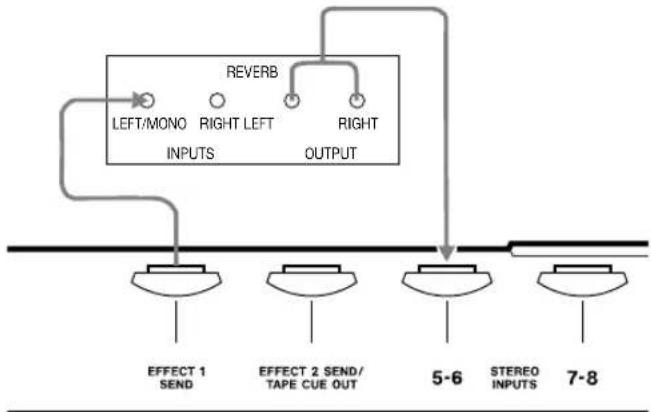
flowchart
graph TD
    A["LEFT/MONO INPUTS"] --> B["RIGHT LEFT OUTPUT"]
    C["REVERB"] --> B
    B --> D["EFFECT 1 SEND"]
    B --> E["EFFECT 2 SEND/TAPE CUE OUT"]
    B --> F["5-6 STEREO INPUTS"]
    B --> G["7-8"]
Mono returns: A special feature of the STEREO INPUTS allows continuously variable control between left and right if desired: a mono effect connected to the 5-6 jack will go to both the LEVEL controls if nothing is plugged into the 7-8 jack.
Patching effects to an input channel: There's no law that says the output of an effects device must be plugged into STEREO INPUTS. They can also be plugged into LINE INPUTS just like any other source, if you are cautious about one thing: make sure the EFFECT controls of those channels are set to the off position (turned all the way to the left). Otherwise, you will be sending the output of the effect device back to itself, which is a kind of feedback. If the effect device is a digital delay, feedback has the same effect as a regeneration (number of echoes) control. An advantage of returning effects to a main channel is that you can EQ the effect return.
| Return Signal | L/MONO Jack Only Connected (R Jack Empty) | L/MONO and R Jacks Both Connected |
STEREO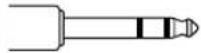 | 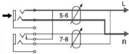 | 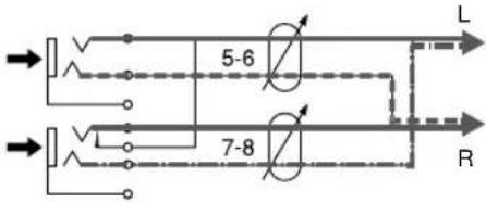 |
MONO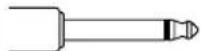 | 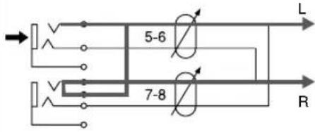 | 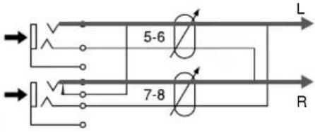 |
Syncing MIDI-Tape — Using the TASCAM MTS-30
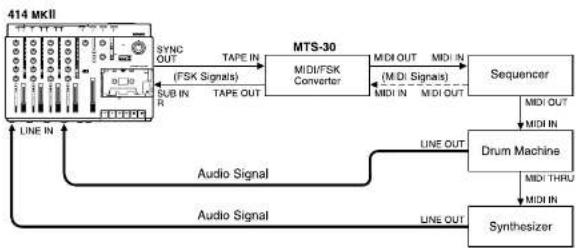
MIDI clocks are themselves a computer type digital language and cannot be recorded on analog tape; it is necessary to convert them to recordable PSK (Frequency Shift Keying) signals using an appropriate converter, such as the MTS-30.
The MTS-30 is not a mere MIDI-FSK converter but translates MIDI clocks into an FSK sync signal containing score "bar" information or "Song Position Pointer", allowing the associated MIDI equipment to stay in sync and follow the tape no matter where you move the tape within a given song. The maximum stability or resolution of the synchronization is ensured by a TASCAM-exclusive error correction circuit in the MTS-30.
1 Connect the TAPE OUT of the MTS-30 to the SUB IN "R" of the 414 MKII, and the SYNC OUT of the 414 MKII to the TAPE IN of the MTS-30.
2 Set the track 4's RECORD FUNCTION switch to R.
3 Set the DBX switch on the 414 MKII to the SYNC position. This defeats the dbx encode/decode for track 4 only.
- When recording FSK signals, adjust the MASTER fader of the 414 MKII to get a reading on the track 4 meter of from -10 to 0 dB.
flowchart
graph TD
    A["414 MKII"] --> B["MTS-30"]
    B --> C["MIDI/FSK Converter"]
    C --> D["Sequencer"]
    D --> E["Drum Machine"]
    E --> F["Synthesizer"]
    F --> G["Audio Signal"]
    G --> H["LINE IN"]
    H --> I["Audio Signal"]
    I --> J["LINE OUT"]
    J --> K["Audio Signal"]
    K --> L["LINE OUT"]
    L --> M["Sub IN R"]
    M --> N["TAPE OUT"]
    N --> O["TSX Signals"]
    O --> P["TAPE OUT"]
    P --> Q["SYNC OUT"]
    Q --> R["TSX Signals"]
    R --> S["TAPE OUT"]
    S --> T["TSX Signals"]
    T --> U["TSX Signals"]
    U --> V["TAPE OUT"]
    V --> W["TSX Signals"]
    W --> X["TAPE OUT"]
    X --> Y["TAPE OUT"]
    Y --> Z["TAPE OUT"]
    Z --> AA["TAPE OUT"]
    AA --> AB["TAPE OUT"]
    AB --> AC["TAPE OUT"]
    AC --> AD["TAPE OUT"]
    AD --> AE["TAPE OUT"]
    AE --> AF["TAPE OUT"]
    AF --> AG["TAPE OUT"]
    AG --> AH["TAPE OUT"]
    AH --> AI["TAPE OUT"]
    AI --> AJ["TAPE OUT"]
    AJ --> AK["TAPE OUT"]
    AK --> AL["TAPE OUT"]
    AL --> AM["TAPE OUT"]
    AM --> AN["TAPE OUT"]
    AN --> AO["TAPE OUT"]
    AO --> AP["TAPE OUT"]
    AP --> AQ["TAPE OUT"]
    AQ --> AR["TAPE OUT"]
    AR --> AS["TAPE OUT"]
    AS --> AT["TAPE OUT"]
    AT --> AU["TAPE OUT"]
    AU --> AV["TAPE OUT"]
    AV --> AW["TAPE OUT"]
    AW --> AX["TAPE OUT"]
    AX --> AY["TAPE OUT"]
Troubleshooting
| Problem Possible Cause | |
| Playback sounds dull Dirty heads | |
| Playback level is too low Dirty heads | |
| Transport keys not effective Power turned off, or tape not loaded | |
| No recording RECORD FUNCTION set to SAFE, or cassette tab broken | |
| Wrong tracks recorded PAN improperly set | |
| Incorrect playback pitch | PITCH CONTROL set to a different position than during recording |
| Feedback occurs during ping-pong Level is too high or EQ HIGH is excessively boosted recording | |
| Problem Solution | |
| Old tracks are always recorded along with new material monitoring previous tracks | Use the TAPE CUE section instead of the main mixer for |
| Recording is noisy | Make sure that all mixer channel faders are turned down to the minimum level except the ones that you are using. Also, increase the volume controls of the instruments you are recording — the 414 MKII channel and master faders should not have to be "full up" at any time |
| Incorrect tape sync | Try re-recording sync tones by adjusting the channel fader so that the track 4 meter reads between -10 dB and 0 dB |
Features and Controls
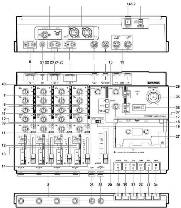
414 MKII MIXER
-
POWER switch (on the rear panel): Turns the 414 MKII on and off.
-
DC IN 12 V connector (on the rear panel): This is for connection of the provided TASCAM PS-P414 AC adaptor only.
Input Section
-
MIC/LINE IN jacks (Channels 1-4): These 1/4" jacks accept unbalanced signals ranging from -50 dBV (3 mV) to -10 dBV (0.3 V), depending on the setting of the TRIM control (#13).
-
INPUT L & R (on the rear panel): These XLR-type connectors accept balanced signals. They are mainly intended for use with dynamic microphones, but the nominal input level may be adjusted from -60 to -20 dBV depending on the setting of the TRIM control. Note that if a signal source is connected to the front MIC/LINE IN jack corresponding to the XLR-type connector where a microphone is connected (L=1 or 3, R=2 or 4), the signal input here at the INPUT (L/R) connector will be ignored by the 414 MKII.
-
GUITAR IN & TRIM control (on the rear panel): This 1/4" jack has an impedance of 1MΩ and is intended for use with electric guitars, basses, etc. Adjust the gain from this jack to channels 1 - 4 with the TRIM control here (turning it clockwise increases the signal level).
-
SUB IN L and R jacks: These jacks are for cascade connection of an outboard mixer, etc. The signal input to these jacks is sent to the MASTER fader. Nominal input level is -10 dBV (0.3 V).
The SUB IN R jack is also used to accept FSK-converted MIDI sync signals from devices such as the optional TASCAM MIDI-Tape Synchronizer MTS-30.
- EQ HIGH: These control the tonality of the high or "treble" frequencies. Turn them to the right to boost the signal's high frequency content emphasizing brilliance or brightness. Turn them to the
left to cut the high frequency content, if the signal sounds too harsh or shrill. The EQ shelving point is 10 kHz.
-
EQ LOW: Turn the controls to the right to boost bass frequencies and make the sound relatively heavy. Turn the controls to the left to cut bass and make the sound thinner. The EQ shelving point is 100 Hz.
-
EFFECT 1 send controls: These controls get their signal from a point just after the channel fader (i.e., "post fader send") and route the corresponding channel signal to the EFFECT 1 SEND jack. Turn the control to the right to increase volume to the EFFECT 1 SEND jack.
-
EFFECT 2/TAPE CUE controls: These controls get their signal after the channel fader and route the signal to the EFFECT 2 SEND jack, or are used to adjust the tape playback level sent to the monitor section, as determined by the EFFECT 2/TAPE CUE select switch (#19).
-
PAN controls: These controls allow you to create stereo mixes by sending the signal from the channel fader in continuously variable degrees to the left or right sides of the stereo mix at mixdown time.
-
INPUT select switches: These are used to control what the source of the channel is:
The upper position (TAPE) is used during mix-down or bouncing tracks.
The center position is GUITAR, which selects the source at the GUITAR IN jack (#5). Turn the guitar TRIM control all the way to the left.
The lower position (MIC/LINE) is used when recording microphones/instruments (in tracking or overdubbing).
-
TRIM controls: These linear controls are used to set the preamplification level on the MIC/LINE IN(puts) or INPUT (L, R). When TRIM is pulled full down, the preamplifier gain is low, allowing the jack to accept line level sources such as electronic instruments. As you push TRIM up, the preamplifier gain increases, and when you push TRIM full up, the nominal input sensitivity increases to -50 dBV (3 mV).
-
Channel faders: These linear controls vary the level feeding the Master section.
The nominal setting position is between 7 and 8 (shaded area).
Stereo Input Section
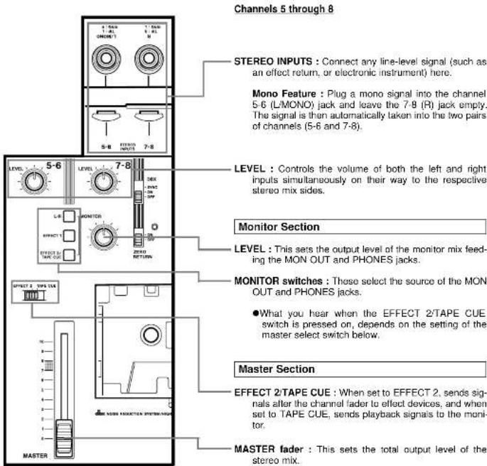
- STEREO INPUTS (Ch.5-6/7-8): Connect the outputs of your effects devices to these 1/4" jacks.
These jacks can also be used as additional line inputs. Nominal input level is -10 dBV (0.3 V).
See also "How to Connect Your Effects Devices", p.28.
- LEVEL controls: These rotary controls vary the level feeding the Master section.
The nominal setting position is about 2 o'clock.
Monitor Section
-
MONITOR level control: This affects signal from the MONITOR switches and sets the level you'll hear in the headphones/monitor speakers.
-
MONITOR switches: Used to select a signal or signals to send to the PHONES and MON OUT jacks. When the L-R switch is on, the left mix is heard on the left side, and the right mix on the right side. The EFFECT 1 switch allows you to check the channel signal going to the corresponding send jack. The third switch is used to check the channel signal going to the EFFECT 2 SEND jack or the signal from the recorder, depending on the setting of the switch with the same label located to the right of the track 4 meter.
Master Section
- EFFECT 2/TAPE CUE select switch:
Depending on the setting of this switch, each channel's EFFECT 2/TAPE CUE control is switched to send the MIC/LINE input to effects devices or the signal coming back from the recorder to the musicians in the studio.
- MASTER fader: Used to adjust the stereo mix level. The signal fed to this fader comes from each channel's PAN control. The safe operating zone is between 7-8 on the scale.
Output Section
-
SYNC OUT jack: Sync tones recorded on track is sent out of this jack, for MIDI instruments to play synced up to the tape. See also the section, Syncing MIDI-Tape.
-
LINE OUT L and R jacks: These jacks are the line-level outputs from the MASTER fader. The L and R jacks are typically connected to your 2-track master recorder at MIXDOWN. The LINE OUT jacks can also be used to send the mixer outputs of the 414 MKII to the sub inputs of a larger mixer.
-
MON OUT L and R jacks: These provide a line level version of the same signal that feeds the PHONES jack and may be connected to your control room speaker amplifier.
-
EFFECT 1 SEND jack: The signal available at this jack comes from post-fader, for connection to effects devices. Nominal level is -10 dBV (0.3 V).
-
EFFECT 2 SEND /TAPE CUE OUT jack:
This jack is for connection to an additional effects device, or to a studio speaker amplifier. The signal source is determined by the EFFECT 2/TAPE CUE select switch (#19). Nominal output level is -10 dBV (0.3 V).
- PHONES jack (on the front panel):
Connect any stereo headphones with a 1/4" stereo TRS 3-conductor plug to this jack.
414 MKII RECORDER
Cassette Loading and dbx System
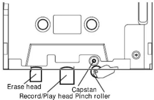
- Cassette compartment door: To insert or remove a cassette, pull the door open. Once a cassette is inserted, be sure to close the door to prevent objects, dust or liquids from falling into the tape path.
Tape path components
- DBX switch : When this switch is set to its ON position, the built-in dbx noise reduction system for all 4 tracks is turned on. This is the normal position for all recording and playback.
When it is set to the SYNC position, Track 4 is disconnected from the dbx system, so the process does not affect the sync signals going to and from track 4, but tracks 1-3 still go through the dbx encode/decode process. Use the SYNC position for recording and playback of FSK sync or SMPTE time code.
The OFF position turns off the dbx noise reduction completely. Use this position when playing back tapes made with no noise reduction.
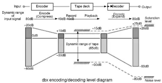
The dbx NR system provides a net noise reduction (broadband, not just hiss) of about 30 dB, and also permits a net gain in tape headroom of about 10 dB, allowing recordings over a 90 dB dynamic range.
Transport Controls
-
RECORD key : Pressing this key alone has no effect. Pressing it together with PLAY (▷) activates recording if one or more RECORD FUNCTION switches are previously set to a different position from SAFE and the REC indicators blink.
-
PLAY key:
a) Press this key alone to start playback.
b) If pressed together with RECORD, recording ("punch in") starts.
- REW key: Winds tape at high speed in reverse direction.
- F FWD key: Winds tape at high speed in the forward direction.
- STOP key: Stops any tape motion and disables all transport modes.
- PAUSE key: Temporarily stops play or recording. To resume the function interrupted, press PAUSE off.
- PITCH CONTROL dial: Varies tape speed in record and play modes by up to approximately ±10%. Turn the dial to the left to lower the speed, or to the right to increase the speed. Set the dial to the center "0" position to run tape at a standard speed of 9.5 cm/sec.
This can be used to save slightly out-of-tune parts, or to create sound effects such as flanging.
CAUTION: The PITCH CONTROL dial affects recording speed also. Check to make sure that the dial is at its center "0" position unless you are using the function intentionally.
- Tape counter: Displays the distance the tape has moved from a zero reference point selected by pressing the adjacent button.
- ZERO RETURN switch: When this switch is set to ON, and you press REW, the tape will stop at the counter 000 point. If the tape overshoots, it is because of inertia, and it is normal.
The associated LED blinks to show that the tape is on its way to the counter zero point. When this point is reached the LED lights solidly.
Track Controls
- REMOTE PUNCH IN/OUT jack (on the front panel): For connection to an optional RC-30P remote footswitch.
- RECORD FUNCTION switches 1-4: These switches put the respective tracks into Record Ready. Recording starts when RECORD is pressed together with PLAY.
In the center position (SAFE) no recording takes place.
NOTE
Don't operate the RECORD FUNCTION switches to punch in and out. Otherwise, "clicks" will remain on tape.
The RECORD FUNCTION switches also select what source will be recorded. For example, the switch for track 1 selects either the single source plugged into Channel 1 of the mixer, or the entire stereo Left mix (which may have as many as six sources). The other RECORD FUNCTION switches work in the same way, selecting either the same-numbered channels or the stereo mix : Left mix for Tracks 1 & 3, Right mix for Tracks 2 & 4.
Displays
- Track level meters 1-4: These meters show the record level coming either from each channel's fader or from the MASTER fader (the first and the third meters register the level from the left buss, the second and the fourth meters register the level from the right buss). If a track or tracks are in Safe mode the corresponding meters show the playback level.
- Track REC indicators: They show the individual track's status as selected by the RECORD FUNCTION switches (#39).
| Track REC indicator Track status | |
| Off Safe | |
| Blinking Record Ready | |
| Steady indication Record | |
Even though the heads used in your 414 MKII have high wear resistance and are rigidly constructed, performance degradation or electro-mechanical failure can be prevented if maintenance is performed regularly.
CLEANING
The first things you will need for maintenance are not expensive. The whole kit with the swabs and fluids you will need for months will cost less than a couple of high quality cassettes.
We cannot stress the importance of cleaning too much. Clean up before each session. Clean up after every session. Clean up every time you take a break in the middle of a session.
DEGAUSSING (DEMAGNETIZING)
A little stray magnetism can become quite a big nuisance in tape recording. It only takes a small amount (0.2 Gauss) to cause trouble on the record head. Playing 10 cassettes will put about that much charge on the heads. A little more than that (0.7 Gauss) will start to erase high frequency signals on previously recorded tapes. You can see that it's worth taking the trouble to degauss regularly.
A clean and properly demagnetized tape recorder will maintain its performance without any other attention for quite a while. It won't ruin previously recorded material, nor will getting it back to original specifications be difficult.
Cleaning the Heads and Tape Guides
All heads and metal parts in the tape path must be cleaned after every 6 hours of operation, or before starting and after ending a recording session.
- Open the cassette door.
- Using a good head cleaning fluid and a cotton swab, clean the heads and tape guides until the swab comes off clean, wipe off any excess cleaning fluid with a dry swab.
Care and Maintenance How the dbx Works
Cleaning the Pinch Roller
Clean the pinch roller at least once each day the deck is used. Use a good rubber cleaner.
- Clean the pinch roller with a cotton swab moistened with rubber cleaner, until there is no visible residue on the pinch roller.
- Using a clean cotton swab, wipe off all excess rubber cleaner from the pinch roller. Make certain that there is no foreign matter remaining on the pinch roller.
Cleaning the Capstan Shaft
After cleaning the pinch roller, clean the capstan shaft with a cotton swab moistened with head cleaning fluid.
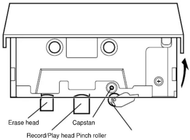
Degaussing the Tape Path
Hold the degausser about 1 m (3 feet) away from the recorder. Turn it on, slowly move into the tape path. Move the degausser slowly back and forth, touching lightly all metal parts in the tape path. Slowly move it away again to at least 1 m (3 feet) from the recorder before turning it off.
CAUTION
If the surface of the unit gets dirty, wipe the surface with a soft cloth or use a diluted neutral cleaning fluid. Clean off thoroughly. Do not use thinner, benzine, or alcohol, as they may damage the surface of the unit.
The dbx system is a wide-band compression-expansion system which provides a net noise reduction (broadband, not just hiss) of a little more than 30 dB. In addition, the compression during recording permits a net gain in tape headroom of about 10 dB.
A compression factor of 2:1 is used before recording; then, 1:2 expansion on reproduce. These compression and expansion factors are linear in decibels and allow the system to produce tape recordings with over a 90 dB dynamic range – an important feature, especially when you're making live recordings. The dbx system employs RMS level sensors to eliminate compressor-expander tracking errors due to phase shifts in the tape recorder, and provides excellent transient tracking capabilities.
To achieve a large reduction in audible tape hiss, without danger of overload or high-frequency self-erasure on the tape, frequency pre-emphasis and de-emphasis are added to the signal and RMS level sensors.
flowchart
graph LR
    A["Input"] --> B["Encoder"]
    B --> C["Tape deck"]
    C --> D["Decoder"]
    D --> E["Output"]

    subgraph Input Signal
        F["80dB"] --> G["Encode (Compress)"]
        G --> H["Record 40dB 40dB"]
        H --> I["Playback"]
        I --> J["Decode (Expand)"]
        J --> K["80dB"]
        L["Saturation level"] --> M["+25dB"]
        N["+20dB"] --> O["+15dB"]
        P["0dB"] --> Q["+10dB"]
        R["-60dB"] --> S["-30dB"]
        T["-50dB"] --> U["-60dB"]
        V["-80dB"] --> W["Noise level"]
    end

    subgraph Dynamic Range of Input Signal
        X["+20dB"] --> Y["+10dB"]
        Z["0dB"] --> AA["+15dB"]
        AB["-60dB"] --> AC["-30dB"]
        AD["-50dB"] --> AE["-60dB"]
        AF["+25dB"] --> AG["+20dB"]
    end
SUBSONICS AND INTERFERENCE
The dbx system incorporates an effective bandpass filter. This filter suppresses undesirable subsonic frequencies to keep them from introducing errors into the encode or decode process. However, if rumble from trains or trucks is picked up by your microphone and fed to the dbx system, modulation of the program material during low level passages may occur. This low-frequency component will not itself be passed through the recorder and so, will not be present at reproduce for proper decoding. If this low-level decoding error is encountered, and subsonics are suspected, we suggest the addition of a suitable high-pass filter in the microphone line.
Specifications
MECHANICAL CHARACTERISTICS
Tape: Compact Cassette (C-60 to 90), High-Bias (CrO2)
Track Format: 4-track/4-channel
Head Configuration:
4-channel record play (permalloy) x 1
4-channel erase (ferrite) x 1
Motor: DC servo motor x 1
Tape Speed: 9.5 cm/sec. (3-3/4 ips)
Pitch Control: ± 10 % (approx.)
Wow and Flutter: 0.2% WRMS or less
Fast Winding Time: 115 sec. (approx.) with C-60
Dimensions (W x H x D) 367 x 100 x 247 mm
(14-7/16" x 3-15/16" x 9-3/4")
Weight: 2.1 kg (4-10/16 lbs.)
ELECTRICAL CHARACTERISTICS
Mixer Section
MIC/LINE INPUT, Ch.1-4: (1/4" phone jack x 4)
Input Impedance: 50 kΩ
Nominal Input Level:
-50 dBV (3 mV) (Trim Max.)
-10 dBV (0.3 V) (Trim Min.)
Maximum Input Level:
+5 dBV (1.8 V) (Trim Min.)
BAL MIC INPUT (XLR TYPE x 2)
Input Impedance: 5 kΩ
Nominal Input Level:
-60 dBV (1 mV) (Trim Max.)
-20 dBV (0.1 V) (Trim Min.)
Maximum Input Level:
-5 dBV (0.56 V) (Trim Min.)
GUITAR INPUT (1/4" phone jack x 1)
Input Impedance: 1 MΩ
Nominal Input Level
-50 dBV (3 mV) (Trim Max.)
-10 dBV (0.3 V) (Trim Min.)
Maximum Input Level:
0 dBV (1 V) (Trim Min.)
STEREO INPUT, Ch.5-6/7-8:
(1/4" stereo phone jack x 2)
Input Impedance: 10 kΩ
5 kΩ (L / MONO)
Nominal Input Level: -10 dBV (0.3 V)
Maximum Input Level: +5 dBV (1.8 V)
SUB INPUT (RCA jack x 2):
Input Impedance: 10 kΩ
Nominal Input Level: -10 dBV (0.3 V)
Maximum Input Level: +5 dBV (1.8 V)
LINE OUTPUT (RCA jack x 2):
Output Impedance: 100 Ω
Nominal Output Level: -10 dBV (0.3 V)
Maximum Output Level: +5 dBV (1.8 V)
EFFECT 1 SEND (1/4" phone jack x 1):
Output Impedance: 100 Ω
Nominal Output Level: -10 dBV (0.3 V)
Maximum Output Level: +5 dBV (1.8 V)
EFFECT 2 SEND/TAPE CUE OUT
(1/4" phone jack x 1):
Output Impedance: 100 Ω
Nominal Output Level: -10 dBV (0.3 V)
Maximum Output Level: +5 dBV (1.8 V)
SYNC OUT (RCA jack x 1):
Output Impedance: 100 Ω
Nominal Output Level: -10 dBV (0.3 V)
MON OUT (RCA jack x 2):
Output Impedance: 1 kΩ
Nominal Output Level: -10 dBV (0.3 V)
Maximum Output Level: +5 dBV (1.8 V)
PHONES (1/4" stereo phone jack x 1):
Nominal Load Impedance: 30 Ω
Maximum Output Level: 60 mW + 60mW
Equalizer:
HIGH (Shelving): 10 kHz, ±10 dB
LOW (Shelving): 100 Hz, ±10 dB
Frequency Response:
MIC INPUT to LINE OUTPUT:
20 Hz to 20 kHz ±3 dB
LINE INPUT TO LINE OUTPUT:
LINE INPUT to MONITOR OUTPUT:
20 Hz to 20 kHz ±2 dB
LINE INPUT to EFFECT OUTPUT:
20 Hz to 20 kHz ±2 dB
LINE INPUT to PHONES:
40 Hz to 20 kHz ±3 dB
Signal-to-Noise Ratio:
(20 Hz to 20 kHz, B.P.F. inserted)
1 MIC INPUT to LINE OUTPUT 65 dB
(at a nominal input level of -60 dBV)
4 MIC INPUTS to LINE OUTPUT 60 dB
(at a nominal input level of -60 dBV) 1 LINE INPUT to LINE OUTPUT 75
LINE INPUT (8 LINE OUTPUT) /5 dB (at a nominal input level of -10 dBV)
4 LINE INPUTS to LINE OUTPUT 70 dB
(at a nominal input level of -10 dBV)
Distortion:
1 MIC INPUT to LINE OUTPUT 0.05%
(at 1 kHz, 15 dB above nominal input level
with 30 kHz low-pass filter inserted)
1 LINE INPUT to LINE OUTPUT 0.03%
(at 1 kHz, nominal input level with 30 kHz
low-pass filter inserted;
Crosstalk: 60 dB (at 1 kHz, nominal input level with 1 kHz band pass filter inserted)
Recorder Section
Record Channel: 4-track single direction
Noise Reduction: dbx* Type II
Overall Frequency Response:
40 Hz to 10 kHz, ±3 dB (wihtout dbx)
Overall Signal-to-Noise Ratio: 85 dB
(at 1 kHz, ref. to 3% THD, *A* weighted.
with dbx)
Total Harmonic Distortion (THD): 2.0%
(at 1 kHz, nominal input level, with dbx)
Channel Separation: 40 dB
(at 1 kHz, nominal input level, with dbx)
Erasure: 65 dB or greater (at 1 kHz, B.P.F. inserted)
Others
Power Requirements
USA/CANADA: 120 V AC, 60 Hz
U.K./EUROPE: 230 V AC, 50 Hz
AUSTRALIA: 240 V AC, 50 Hz
Power Consumption: 11 W, via the supplied
PS-P414 AC adaptor
In these specifications, 0 dBV is referenced to 1 Volt.
Actual voltage levels are also given in parentheses (0.316 V for -10 dBV rounded off to 0.3 V).
*dbx is a registered trademark of dbx Incorporated.
■Changes in specifications and features may be
made without notice of obligation
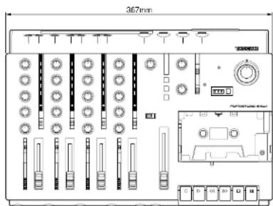
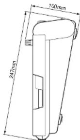
Block Diagram
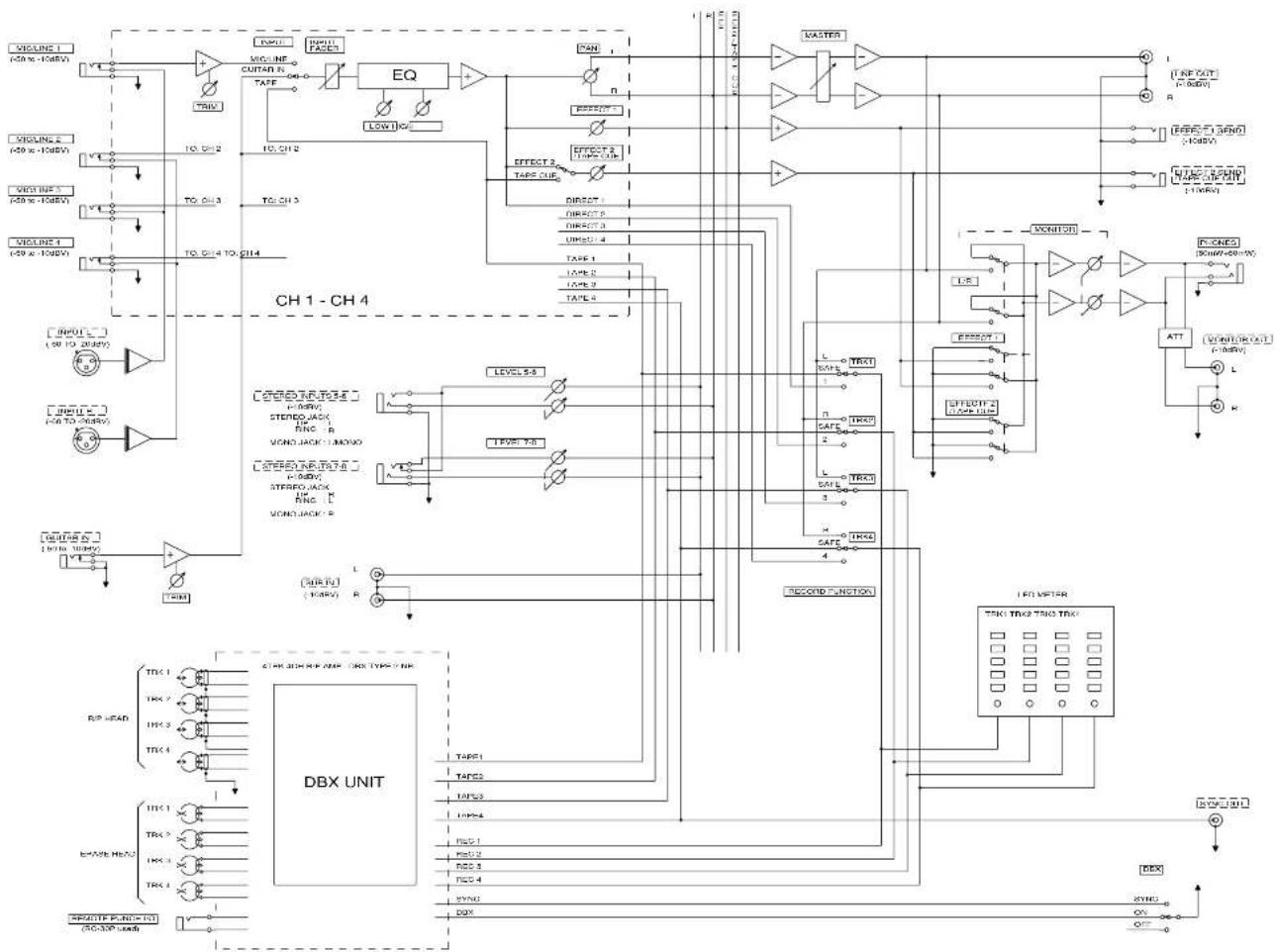
flowchart
graph TD
    subgraph CH1 - CH4
        A["Input L (50 TO 200kV)"] --> B["THC1"]
        C["Input U (50 TO 200kV)"] --> D["THC2"]
        E["Input V (50 TO 200kV)"] --> F["THC3"]
        G["Input W (50 TO 200kV)"] --> H["THC4"]
    end

    subgraph DBX UNIT
        I["TRC1"] --> J["THC1"]
        K["TRC2"] --> L["THC2"]
        M["TRC3"] --> N["THC3"]
        O["TRC4"] --> P["THC4"]
        Q["TRC5"] --> R["THC5"]
        S["TRC6"] --> T["THC6"]
        U["TRC7"] --> V["THC7"]
        W["TRC8"] --> X["THC8"]
        Y["TRC9"] --> Z["THC9"]
        AA["TRC10"] --> AB["THC10"]
    end

    subgraph CH1 - CH4
        AC["LEVEL 5-8"] --> AD["THC10"]
        AE["LEVEL 7-8"] --> AF["THC7-8"]
        AG["TAPF1"] --> AH["THC10"]
        AI["TAPF2"] --> AJ["THC7-8"]
        AK["TAPF3"] --> AL["THC7-8"]
        AM["TAPF4"] --> AN["THC7-8"]
        AO["TAPF5"] --> AP["THC7-8"]
        AQ["TAPF6"] --> AR["THC7-8"]
        AS["TAPF7"] --> AT["THC7-8"]
        AU["TAPF8"] --> AV["THC7-8"]
        AW["TAPF9"] --> AX["THC7-8"]
        AY["TAPF10"] --> AZ["THC7-8"]
    end

    subgraph CH1 - CH4
        BA["TARE 1"] --> BB["TARE 2"]
        BC["TARE 3"] --> BD["TARE 4"]
        BE["TARE 5"] --> BF["TARE 6"]
        BG["TARE 7"] --> BH["TARE 8"]
        BI["TARE 8"] --> BJ["TARE 9"]
        BK["TARE 10"] --> BL["TARE 11"]
        BM["TARE 12"] --> BN["TARE 13"]
        BO["TARE 14"] --> BP["TARE 14"]
    end

    subgraph DBX UNIT
        BQ["TAPF1"] --> BR["TAPF2"]
        BS["TAPF3"] --> BT["TAPF4"]
        BU["TAPF5"] --> BV["TAPF6"]
        BW["TAPF7"] --> BX["TAPF8"]
        BY["TAPF9"] --> BZ["TAPF10"]
    end

    subgraph CH1 - CH4
        CA["TARE 1"] --> CB["TARE 2"]
        CC["TARE 3"] --> CD["TARE 4"]
        DE["TARE 5"] --> DF["TARE 6"]
        DG["TARE 7"] --> DH["TARE 8"]
        DI["TARE 8"] --> DJ["TARE 9"]
        DK["TARE 10"] --> DL["TARE 11"]
        DM["TARE 12"] --> DN["TARE 13"]
        DO["TARE 14"] --> DP["TARE 14"]
    end

    subgraph DBX UNIT
        EQ["EQ"] --> BR
        EQ --> DC
        EQ --> DA
        EQ --> DW
        EQ --> BX
    end

    subgraph CH1 - CH4
        EQ --> RX["NAN"]
        RX --> SW["NH"]
        SW --> TX["NH"]
        TX --> AU["NH"]
        AU --> AV["NH"]

    subgraph CH1 - CH4
        EQ --> CX["EFFECT 2 TAPE CUE"]
        CX --> CY["DIRECT 3 DIRECT 4 TAPE CUE"]
        CX --> CZ["LTRX1"]
        CX --> CE["LTRX2"]
        CX --> CF["SAFE"]
        CX --> CG["LTRX3"]
        CX --> DH["SAFE"]
        CX --> ID["HTRX4"]

    subgraph DBX UNIT
        EQ --> BE2["LTRX1"]
        EQ --> BE3["LTRX2"]
        EQ --> BE4["LTRX3"]

    end

    subgraph CH1 - CH4
        EQ --> BF2["LTRX1"]
        EQ --> BF3["LTRX2"]
        EQ --> BF4["LTRX3"]

    subgraph DBX UNIT
        EQ --> BF5["LTRX1"]
        EQ --> BF6["LTRX2"]
        EQ --> BF7["LTRX3"]

    end

    subgraph CH1 - CH4
        EQ --> BF8["LTRX1"]
        EQ --> BF9["LTRX2"]
        EQ --> BF10["LTRX3"]

    subgraph DBX UNIT
        EQ --> BF10["LTRX1"]
        EQ --> BF11["LTRX2"]
        EQ --> BF12["LTRX3"]

    end

    subgraph CH1 - CH4
        EQ --> BF13["LTRX1"]
        EQ --> BF14["LTRX2"]
        EQ --> BF15["LTRX3"]

    end

    subgraph DBX UNIT
        EQ --> BF16["LTRX1"]
        EQ --> BF17["LTRX2"]
        EQ --> BF18["LTRX3"]

    end

    subgraph CH1 - CH4
        EQ --> BF19["LTRX1"]
        EQ --> BF20["LTRX2"]
        EQ --> BF21["LTRX3"]

    end

    subgraph DBX UNIT
        EQ --> BF30["LTRX1"]
        EQ --> BF31["LTRX2"]
        EQ --> BF32["LTRX3"]

    end

    subgraph CH1 - CH4
        EQ --> BF33["LTRX1"]
        EQ --> BF34["LTRX2"]
        EQ --> BF35["LTRX3"]

    end

    subgraph DBX UNIT
        EQ --> BF36["LTRX1"]
        EQ --> BF37["LTRX2"]
        EQ --> BF38["LTRX3"]

    end

    subgraph CH1 - CH4
        EQ --> BF39["LTRX1"]
        EQ --> BF40["LTRX2"]
        EQ --> BF41["LTRX3"]

    end

    subgraph DBX UNIT
        EQ --> BF42["LTRX1"]
        EQ --> BF43["LTRX2"]
        EQ --> BF44["LTRX3"]

    end

    subgraph CH1 - CH4
        EQ --> BF45["LTRX1"]
        EQ --> BF46["LTRX2"]
        EQ --> BF47["LTRX3"]

    end

    subgraph DBX UNIT
        EQ --> BF48["LTRX1"]
        EQ --> BF49["LTRX2"]
        EQ --> BF50["LTRX3"]

    end

    subgraph CH1 - CH4
        EQ --> BF51["LTRX1"]
        EQ --> BF52["LTRX2"]
        EQ --> BF53["LTRX3"]

    end

    subgraph DBX UNIT
        EQ --> BF54["LTRX1"]
        EQ --> BF55["LTRX2"]
        EQ --> BF56["LTRX3"]

    end

    subgraph CH1 - CH4
        EQ --> BF57["LTRX1"]
        EQ --> BF58["LTRX2"]
        EQ --> BF59["LTRX3"]

    end

    subgraph DBX UNIT
        EQ --> BF5A["LTRX1"]
        EQ --> BF5B["LTRX2"]
        EQ --> BF5C["LTRX3"]

    end

    subgraph CH1 - CH4
        EQ --> BF5E["LTRX1"]
        EQ --> BF5F["LTRX2"]
        EQ --> BF5G["LTRX3"]

    end

    subgraph DBX UNIT
        EQ --> BF5H["LTRX1"]
        EQ --> BF5I["LTRX2"]
        EQ --> BF5J["LTRX3"]

    end

    subgraph CH1 - CH4
        EQ --> BF60["LTRX1"]
        EQ --> BF61["LTRX2"]
        EQ --> BF62["LTRX3"]

    end

    subgraph DBX UNIT
        EQ --> BF63["LTRX1"]
        EQ --> BF64["LTRX2"]
        EQ --> BF65["LTRX3"]

    end

    subgraph CH1 - CH4
        EQ --> BF66["LTRX1"]
        EQ --> BF67["LTRX2"]
        EQ --> BF68["LTRX3"]

    end

    subgraph DBX UNIT
        EQ --> BF69["LTRX1"]
        EQ --> BF70["LTRX2"]
        EQ --> BF71["LTRX3"]

    end

    subgraph CH1 - CH4
        EQ --> BF72["LTRX1"]
        EQ --> BF73["LTRX2"]
        EQ --> BF74["LTRX3"]

    end

    subgraph DBX UNIT
        EQ --> BF75["LTRX1"]
        EQ --> BF76["LTRX2"]
        EQ --> BF77["LTRX3"]

    end

    subgraph CH1 - CH4
        EQ --> BF78["LTRX1"]
        EQ --> BF79["LTRX2"]
        EQ --> BF80["LTRX3"]

    end

    subgraph DBX UNIT
        EQ --> BF81["LTRX1"]
        EQ --> BF82["LTRX2"]
        EQ --> BF83["LTRX3"]

    end

    subgraph CH1 - CH4
        EQ --> BF84["LTRX1"]
        EQ --> BF85["LTRX2"]
        EQ --> BF86["LTRX3"]

    end

    subgraph DBX UNIT
        EQ --> BF87["LTRX1"]
        EQ --> BF88["LTRX2"]
        EQ --> BF89["LTRX3"]

    end

    subgraph CH1 - CH4
        EQ --> BF8A["RANK"]
        EQ --> BF8B["RANK"]
    end
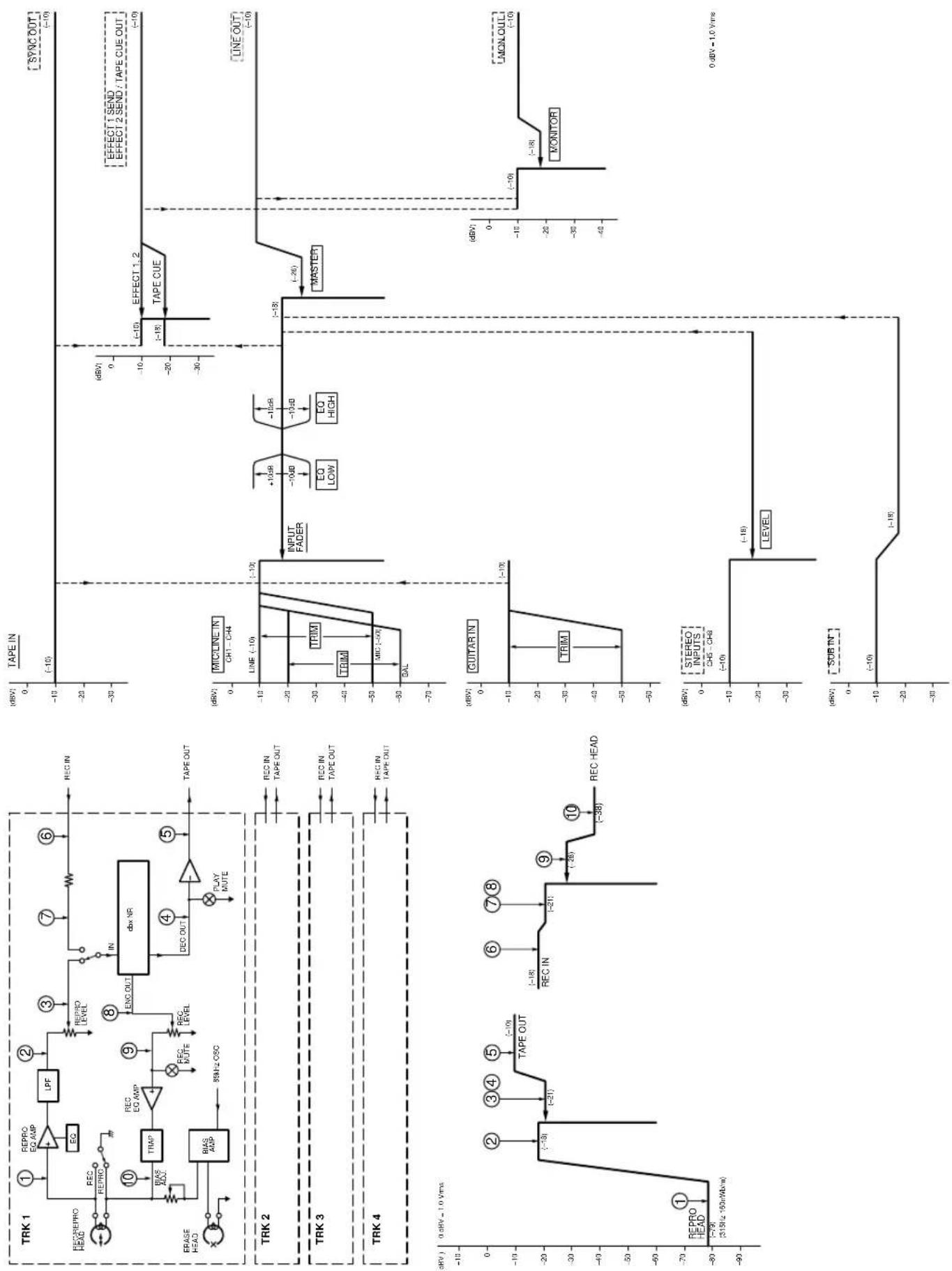
flowchart
graph TD
    subgraph TRK_1
        A["① REPRO EQ AMP"] --> B["EQ"]
        B --> C["LPF"]
        C --> D["② REPRO LEVEL"]
        D --> E["③ REPRO LEVEL"]
        E --> F["④ REC IN"]
        F --> G["⑤ ENCK OUT"]
        G --> H["TRAV NR"]
        H --> I["⑥ REPRO LEVEL"]
        I --> J["⑦ REC IN"]
        J --> K["⑧ ENCK OUT"]
        K --> L["⑨ REPRO LEVEL"]
        L --> M["⑩ TRIAP"]
        M --> N["BLIAS ADJ"]
        N --> O["BRAS ADP"]
        O --> P["55kHz CSC"]
        P --> Q["REPRO EQ AMP"]
        Q --> R["TRIAP"]
        R --> S["BRAS ADP"]
        S --> T["BRAS ADP"]
        T --> U["REPRO EQ AMP"]
        U --> V["TRIAP"]
        V --> W["BRAS ADP"]
        W --> X["BRAS ADP"]
        X --> Y["REPRO EQ AMP"]
        Y --> Z["TRIAP"]
        Z --> AA["BRAS ADP"]
        AA --> AB["BRAS ADP"]
        AB --> AC["BRAS ADP"]
        AC --> AD["BRAS ADP"]
    end

    subgraph TRK_2
        AE["① REPRO HEAD"] --> AF["REPRO EQ AMP"]
        AF --> AG["EQ"]
        AG --> AH["TPF"]
        AH --> AI["TPF"]
        AI --> AJ["TPF"]
        AJ --> AK["TPF"]
        AK --> AL["TPF"]
        AL --> AM["TPF"]
        AM --> AN["TPF"]
        AN --> AO["TPF"]
        AO --> AP["TPF"]
        AP --> AQ["TPF"]
        AQ --> AR["TPF"]

    end

    subgraph TRK_3
        AS["② REPRO HEAD"] --> AT["REPRO EQ AMP"]
        AT --> AU["EQ"]
        AU --> AV["TPF"]
        AV --> AW["TPF"]
        AW --> AX["TPF"]
        AX --> AY["TPF"]
        AY --> AZ["TPF"]

        AC["③ REPRO HEAD"] --> BA["REPRO EQ AMP"]
        BA --> BB["EQ"]
        BB --> BC["TPF"]
        BC --> BD["TPF"]
        BD --> BE["TPF"]
        BE --> BF["TPF"]

        BG["④ REPRO HEAD"] --> BH["REPRO EQ AMP"]
        BH --> BI["EQ"]
        BI --> BJ["TPF"]
        BJ --> BK["TPF"]
        BK --> BL["TPF"]

        BM["⑤ REPRO HEAD"] --> BN["REPRO EQ AMP"]
        BN --> BO["TRAV NR"]

    end

    subgraph TRK_4
        BO --> BP["REPRO EQ AMP"]
        BP --> BQ["TRAV NR"]

    subgraph TAPE_IN
        BQ --> BQIN["-10 dB"]

        BQIN --> BQOUT["-10 dB"]

        BQOUT --> BQOUT1["-10 dB"]

        BQOUT1 --> BQOUT2["-10 dB"]

        BQOUT2 --> BQOUT3["-10 dB"]

        BQOUT3 --> BQOUT4["-10 dB"]

        BQOUT4 --> BQOUT5["-10 dB"]

        BQOUT5 --> BQOUT6["-10 dB"]

        BQOUT6 --> BQOUT7["-10 dB"]

        BQOUT7 --> BQOUT8["-10 dB"]

        BQOUT8 --> BQOUT9["-10 dB"]

        BQOUT9 --> BQOUT10["-10 dB"]

        BQOUT10 --> BQOUT11["-10 dB"]

        BQOUT11 --> BQOUT12["-10 dB"]

        BQOUT12 --> BQOUT13["-10 dB"]

        BQOUT13 --> BQOUT14["-10 dB"]

        BQOUT14 --> BQOUT15["-10 dB"]

        BQOUT15 --> BQOUT16["-10 dB"]

        BQOUT16 --> BQOUT17["-10 dB"]

        BQOUT17 --> BQOUT18["-10 dB"]

        BQOUT18 --> BQOUT19["-10 dB"]

        BQOUT19 --> BQOUT20["-10 dB"]

        BQOUT20 --> BQOUT21["-10 dB"]

        BQOUT21 --> BQOUT22["-10 dB"]

        BQOUT22 --> BQOUT23["-10 dB"]

        BQOUT23 --> BQOUT24["-10 dB"]

        BQOUT24 --> BQOUT25["-10 dB"]

        BQOUT25 --> BQOUT26["-10 dB"]

        BQOUT26 --> BQOUT27["-10 dB"]

        BQOUT27 --> BQOUT28["-10 dB"]

        BQOUT28 --> BQOUT29["-10 dB"]

        BQOUT29 --> BQOUT30["-10 dB"]

        BQOUT30 --> BQOUT31["-10 dB"]

        BQOUT31 --> BQOUT32["-10 dB"]

        BQOUT32 --> BQOUT33["-10 dB"]

        BQOUT33 --> BQOUT34["-10 dB"]

        BQOUT34 --> BQOUT35["-10 dB"]

        BQOUT35 --> BQOUT36["-10 dB"]

        BQOUT36 --> BQOUT37["-10 dB"]

        BQOUT37 --> BQOUT38["-10 dB"]

        BQOUT38 --> BQOUT39["-10 dB"]

        BQOUT39 --> BQOUT40["-10 dB"]

        BQOUT40 --> BQOUT41["-10 dB"]

        BQOUT41 --> BQOUT42["-10 dB"]

        BQOUT42 --> BQOUT43["-10 dB"]

        BQOUT43 --> BQOUT44["-10 dB"]

        BQOUT44 --> BQOUT45["-10 dB"]

        BQOUT45 --> BQOUT46["-10 dB"]

        BQOUT46 --> BQOUT47["-10 dB"]

        BQOUT47 --> BQOUT48["-10 dB"]

        BQUTRIN
    end

    subgraph TAPE_OUT
    C
    D
    E
    F
    G
    H
    I
    J
    K
    L
    M
    N
    O
    P
    Q
    R
    S
    T
    U
    V
    W
    X
    Y
    Z
    AA
    AB
    AC
    AD
    AE
    AF
    AG
    AH
    AI
    AJ
    AK
    AL
    AM
    AN
    AO
    AP
    AQ
    AR
    AS
    AT
    AU
    AV
    AW
    AX
    AY
    AZ
    BA
    BB
    BC
    BD
    BE
    BF
    BG
    BH
    BI
    BJ
    BK
    BL
    BM
    BN
    BO
    BP
    BP

    subgraph GUYARIN
    C
    D
    E
    F
    G
    H
    I
    J
    K
    L
    M
    N
    O
    P

    subgraph STEREO_INPUTS |
    C
    D
    E
    F
    G
    H
    I
    J
    K

    subgraph SUBINT

    C
    D
    E
    F

    subgraph TIME_OUT

    C

    D

    subgraph MONI_OUT

    D

    subgraph MONI_OUT_C

    C

    D

    subgraph MONI_OUT_L

    D

    subgraph MONI_OUT_C_L

    C

    subgraph SUBINT_C

    C

    subgraph SUBINT_L

    C

End

   subgraph TOTAL_OUT
TASCAM
TEAC Professional Division
414MKII
PORTASTUDIO
TEAC CORPORATION
Phone: (0422) 52-5082 3-7-3, Nakacho, Musashino-shi, Tokyo 180-8550, Japan
TEAC AMERICA, INC.
Phone: (323) 726-0303 7733 Telegraph Road, Montebello, California 90640
TEAC CANADA LTD.
Phone: 905-890-8008 Facsimile: 905-890-9888 5939 Wallace Street, Mississauga, Ontario L4Z 1Z8, Canada
TEAC MEXICO, S.A. De C.V
Phone: 5-658-1943 Privada De Corina, No.18, Colonia Del Carmen Coyoacon, Mexico DF 04100
TEAC UK LIMITED
Phone: 01923-819699 5 Marlin House, Marlins Meadow, The Croxley Centre, Watford, Herts. WD1 8YA, U.K.
106 Bay Street, Port Melbourne, Victoria 3207, Australia

- TEAC Professional Division
- 414MKII
- PORTASTUDIO
- OWNER'S MANUAL
- CAUTION:
- CAUTION
- About the weld line
- NOTE FOR U.K. CUSTOMERS
- The Recording System
- The Three Steps to Multitrack
- Signal Flow in the 414 MKII Mixer
- Tape Cue Monitor System
- Multitrack Cassette Recorder
- Track Format and Tape Recommendations
- Tape Speed and Track Format
- Tape Type
- Accidental Erase/Record Protection
- Tape Length
- Optional Accessories
- PORTASTUDIO 414 MKII Brief Guide
- Input Selection and Adjustment
- Channels 1 through 4
- Recorder Controls
- Connections on the Rear Panel
- Let's Try the 414 MKII Mixer
- First, make the following settings :
- Monitor selection
- Monitor level
- TRIM adjustment
- How to Record on Track 1
- Mic level adjustment
- Beginning recording
- Stopping recording
- Putting track into "Safe"
- Track 1 Playback through TAPE CUE
- Selecting TAPE CUE
- Monitor selection
- Locating tape to zero
- Beginning playback
- MONITOR level control setting
- Routing tape signals to TAPE CUE
- Stopping playback
- How to Make an Overdub on Track 2
- Routing input
- Panning
- Channel 1 level
- Master level
- Monitor selection
- Locating tape to zero
- Track selection
- Record level adjustment (TRIM)
- Beginning recording
- Monitoring input/tape
- NOTE
- Stopping recording
- Putting track into "Safe"
- How to Record Tracks 3 and 4
- How to Record Many Sources onto a Single Track
- How to Record a Mix onto Two Tracks Simultaneously
- Recording the stereo channels (5-6 and 7-8):
- Recording on More than Two Tracks Simultaneously : Direct Recording
- How to Mix Down
- Connections
- Master level
- Monitor source
- Routing inputs
- Step-By-Step-Operation Guide
- Playback level
- Review
- Record level
- PUNCH-IN or INSERT Recording
- Preliminary
- Selecting in and out points
- Punch-in Procedure
- Punching-in/out with RECORD
- Bouncing Tracks (Ping-Pong)
- Ping-pong Procedure
- Setting Effect Send Levels
- Setting the Output Level of Effect Devices
- Setting the Mix/Balance Control on Effect Devices
- How to Connect Your Effects Devices
- Syncing MIDI-Tape — Using the TASCAM MTS-30
- Features and Controls
- MKII MIXER
- Input Section
- Stereo Input Section
- Monitor Section
- Master Section
- Output Section
- MKII RECORDER
- Cassette Loading and dbx System
- Transport Controls
- Track Controls
- Displays
- CLEANING
- DEGAUSSING (DEMAGNETIZING)
- Cleaning the Heads and Tape Guides
- Care and Maintenance How the dbx Works
- Cleaning the Pinch Roller
- Cleaning the Capstan Shaft
- Degaussing the Tape Path
- SUBSONICS AND INTERFERENCE
- Specifications
- MECHANICAL CHARACTERISTICS
- ELECTRICAL CHARACTERISTICS
- Mixer Section
- Recorder Section
- Others
- Block Diagram
- TASCAM
- TEAC CORPORATION
Brand : TASCAM
Model : 414MKII
Category : Cassette player