
7207035 - Fan WESTINGHOUSE - Free user manual and instructions
Find the device manual for free 7207035 WESTINGHOUSE in PDF.


| Product Type | Ceiling Fan with LED Light Kit |
| Model Number | 7207035 / 7255735 |
| Brand | Westinghouse |
| Net Weight | 7.60 kg |
| Power Supply | 240 V ~ 50 Hz |
| LED Module | SMJD-3V16W2P3 |
| Fan Speeds | 3 (Low, Medium, High) plus Off via wall control |
| Light Control | On/Off switch on wall control |
| Direction Reversal | Reversible slide switch on motor housing for summer/winter operation |
| Installation Height (minimum) | 2.3 m from floor to blades |
| Mounting Options | Downrod or flush mount (flush mount not to be re-installed with downrod due to safety) |
| Indoor Use | Yes (IP20, not for damp areas) |
| Safety Certifications | AS/NZS SAA-181731-EA |
| Maintenance | Clean with soft brush or lint-free cloth; do not use water; no oiling required |
| Included Components | Mounting bracket, blades, glass, wall control, capacitor, hardware pack |
| Tools Required | Phillips screwdriver, wire cutters, pliers, step ladder |
| Warranty | Not specified; refer to manufacturer |
Frequently Asked Questions - 7207035 WESTINGHOUSE
User questions about 7207035 WESTINGHOUSE
0 question about this device. Answer the ones you know or ask your own.
Ask a new question about this device
Download the instructions for your Fan in PDF format for free! Find your manual 7207035 - WESTINGHOUSE and take your electronic device back in hand. On this page are published all the documents necessary for the use of your device. 7207035 by WESTINGHOUSE.
USER MANUAL 7207035 WESTINGHOUSE
SAA-Bendan LED-Australia-WH18

Westinghouse
OWNER'S MANUAL
Bendan
Please write model number here for future reference:
7255735
7207035
LED Module#: SMJD-3V16W2P3
Net Weight:
7.60 KGS
240V\~50Hz
SAFETY TIPS
READ AND SAVE THESE INSTRUCTIONS
WARNING: TO REDUCE THE RISK OF FIRE, ELECTRIC SHOCK,
OR INJURY TO PERSONS, OBSERVE THE FOLLOWING:
- Proceed with caution. Read all instructions before beginning the installation.
- Only an authorized electrician should execute the installation.
- The installation height, i.e. the distance between the blades and the floor, should be at least 2.3 m.
- (-1.0m-f) Always maintain the distance between the lamp and inflammable materials (curtains, wall, etc.), as indicated on the pictogram.
- Make sure the fan is securely fastened at the ceiling.
- WARNING! Do not use a dimmer type switch to control the fan speed.
- WARNING! To prevent injuries, make sure the blades are not bent and that there are no objects with in the area of rotation.
- WARNING! Due to European safety regulations, if the flush mount option is elected, the fan must not be re-installed utilizing the downrod. If attempted, this may cause a serious injury. When assembling the fan, please follow your local safety regulations.
- WARNING: Do Not use this fan in the same room at the same time as a gas or fuel burning fire, unless the flue has been tested under these conditions of use by a competent person.
- This appliance can be used by children aged from 8 years and above and persons with reduced physical, sensory or mental capabilities or lack of experience and knowledge if they have been given supervision or instruction concerning use of the appliance in a safe way and understand the hazards involved. Children shall not play with the appliance. Cleaning and user maintenance shall not be made by children without supervision.
- Suitable for use indoors.
- Before disassembling light kit, make sure the power supply is disconnected from the main supply. Power supply can be on only after installation is completed.
- The lampshade should not be removed from the light bulb when the power supply is on.
- Replacement of light bulb is only possible when the light kit has cooled down, and the power supply is disconnected from the main supply.
- Make sure the lampshade is in the fixed position when operating the product.
- Means for all poles disconnection having a contact separation that provide full disconnection under over voltage category III conditions must be incorporated in the fixed wiring in accordance with national wiring rules.
- IP20 The fan is designed for indoor use. It is not designed for installation in a bathroom or any damp area. Please ensure that the lamp does not come into contact with water.
- WARNING: If unusual oscillating movement is observed, immediately stop using the ceiling fan and contact the manufacturer, its service agent or suitably qualified persons.
- The replacement of parts of the safety suspension system device shall be performed by the manufacturer, its service agent or suitably qualified persons.
- The fixing means for attachment to the ceiling can be fixed with a sufficient strength to withstand 4 times the weight of the ceiling fan.
- The light source contained in this luminaire shall only be replaced by the manufacturer or his service agent or a similar qualified person.
TOOLS REQUIRED
Phillips Screwdriver
Wire Cutters
Pliers
Step Ladder
FeatUres
DOWNROD
INSTALLATION
VAULTED CEILING
INSTALLATION
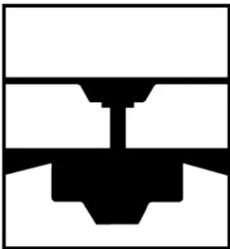
natural_image
Pure mechanical cross-section diagram without any text, numbers, or symbolsFor normal ceilings
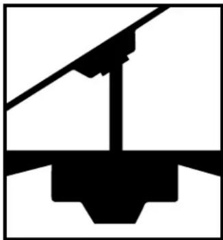
natural_image
Pure mechanical assembly diagram without any text, numbers, or symbolsMay require a longer downrod (sold separately)
PrEPArInG fOr InStALLAtION
1
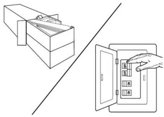
natural_image
Line drawing showing a cabinet with internal compartments and a hand inserting a box into an open door (no text or symbols)Unpack and inspect fan carefully to be certain all contents are included. Turn off power at fuse box to avoid possible electrical shock.
2
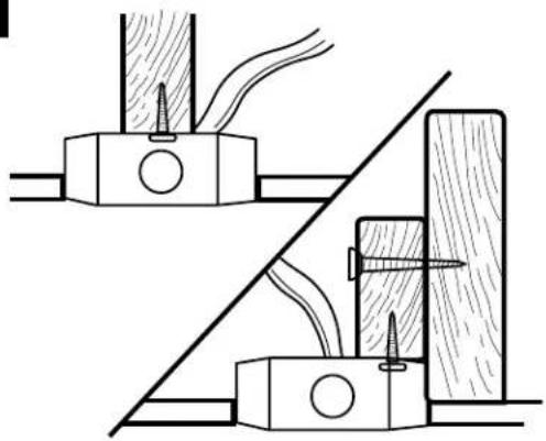
natural_image
Technical diagram showing two mechanical assembly steps with no visible text or symbolsUse metal outlet box suitable for fan support (must support 35 lbs). Before attaching fan to outlet box, ensure the outlet box is securely fastened by at least two points to a structural ceiling member (a loose box will cause the fan to wobble).
MOUNTInG BrACKEt InStALLAtION
3
natural_image
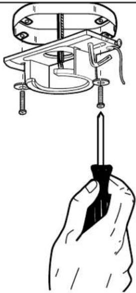
Illustration of a hand holding a screwdriver inserted into a mechanical component (no text or symbols present)Install mounting bracket to outlet box in ceiling using the screws and washers provided with the outlet box.
WlrInG OPtIONs
4
Wiring:
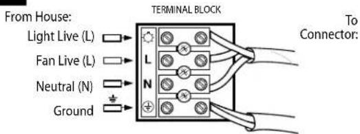
Follow diagram above to make wiring connections to the terminal block on the mounting bracket.
MOUNTING
5
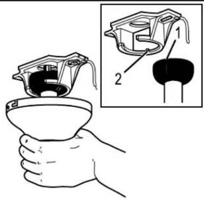
Carefully lift fan assembly onto mounting bracket. Rotate fan until notch on down-rod ball (1) engages the ridge on the mounting bracket (2). This will allow for hands free wiring.
6
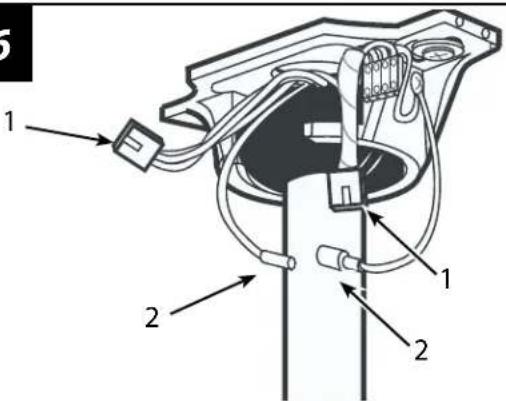
With bracket holding fan assembly, attach the male/female plug connection (1) from the fan to the terminal block. Attach the ground wire (2) from the downrod to the mounting bracket.
secUre t0 ceILING
7
For downrod fans, slide the canopy up to the mounting bracket.
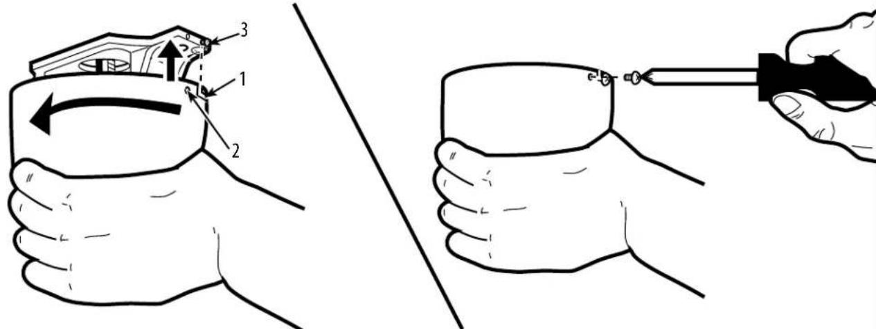
The canopy has two mating slots (1) and two mating holes (2). Position both slots on canopy directly under and in line with two screws in the mounting bracket (3). Lift the canopy, allowing the two screws to slide into the mating slots. Rotate the canopy until both screws from the mounting bracket drop into the slot recesses. Tighten screws securely. Install two screws into the mating holes of the canopy and tighten to secure the canopy to the mounting bracket.
BLADE InStALLAt10n
8
natural_image
Diagram showing a mechanical component with an arrow indicating direction, no text or symbols present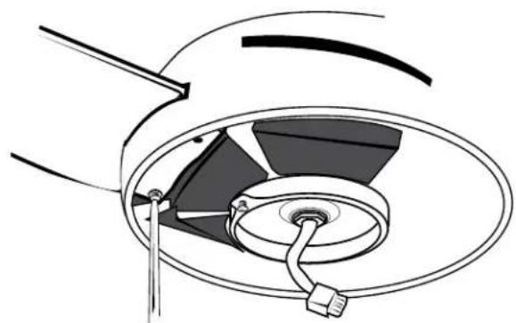
natural_image
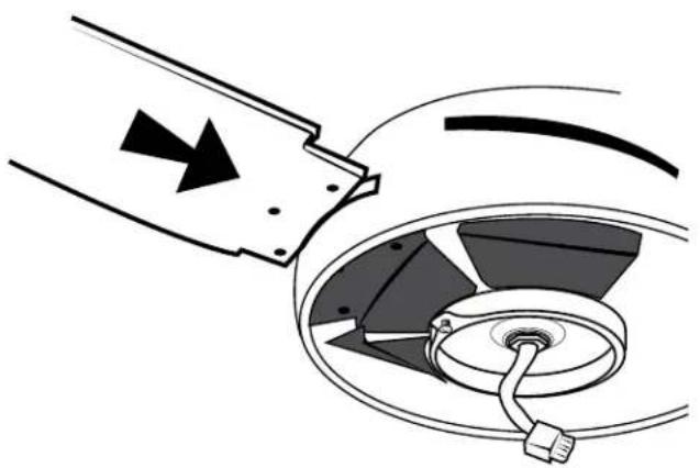
Technical diagram of a mechanical component with a central hub and internal structure (no text or symbols)Insert the blades through the slots on the motor housing as shown, and use the provided blade screws to tighten the blades to the pre-attached blade brackets.
LIGHT fIXturE InStALLAtION
9
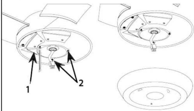
Remove one of the screws on the switch housing plate (1), and loosen, (do not remove) the other two (2).
10
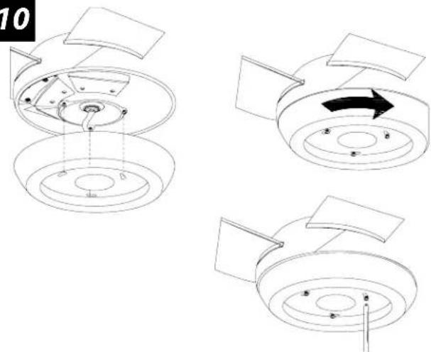
The light kit has 2 keyhole slots. Align the slots on the light kit to the protruding screws from the light kit support plate. Raise the light kit allowing the protruding screws from the support plate to enter the keyhole slots on the light kit. Rotate the light kit clockwise to engage the slots, and tighten screws to secure the light kit.
LIGHT fIXturE InStALLAtION
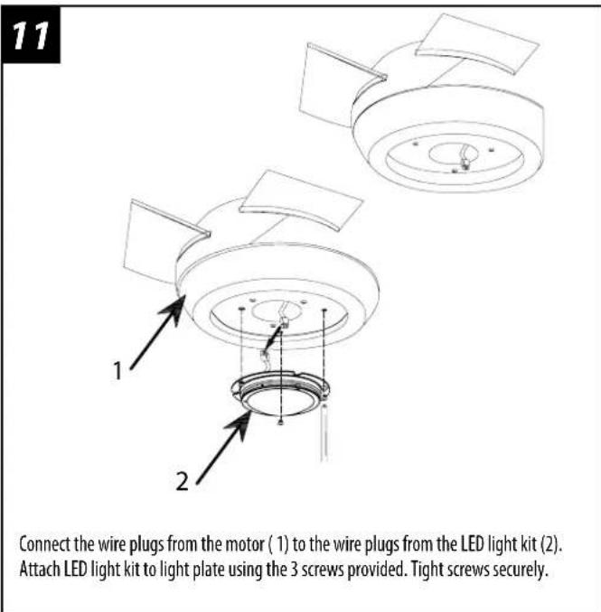
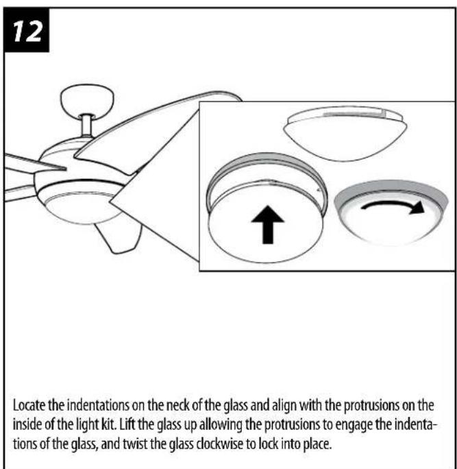
rEVErSIBLE SWItCH OPt10n
13
natural_image
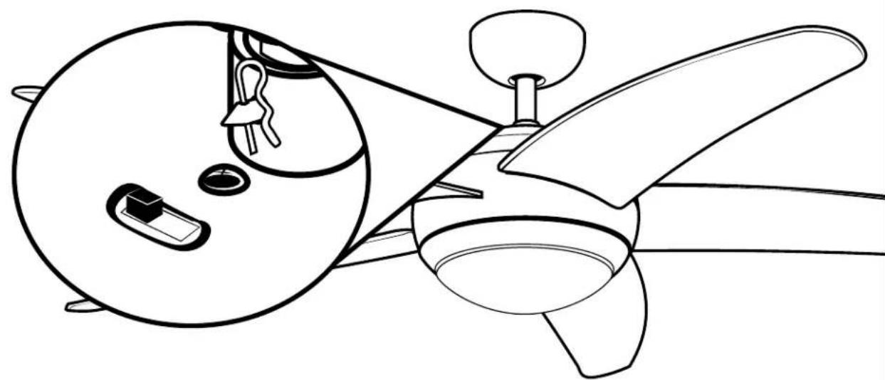
Line drawing of a helicopter's fuselage and cockpit, showing internal components like wings and propellers (no text or symbols)To reverse the direction of the blades, slide the reverse switch (located on the top of the motor housing) to the opposite side. Note: Make sure slide switch is pushed firmly to one side or the other. The fan will not operate with the slide switch in the middle.
WALL COntrOL InStALLAt10n
14
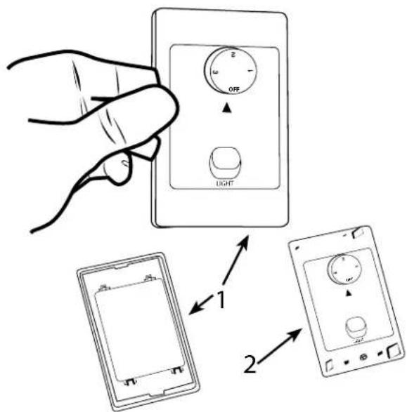
Remove the front cover of the wall control by unsnapping the cover (1) from the control unit (2).
WlrInG t0 tHE WALL COntrOL
15
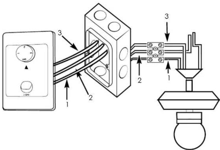
Connect the light control wire from the fan to the terminal block on the wire marked "For light - L", as line art shown on "1"; Connect the 240V hot house wire to the terminal block on the wire marked "TO AC-L240V/50HZ", as line art shown on "2"; Connect the fan control wire from the fan to the terminal block on the wire marked "For fan-L", as line art shown on "3".
OPErAtlOn WALL COntrOL
InStALL WALL COntrOL tO OutLEt BOX
16
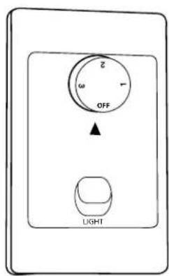
Operation:
Fan Rotary Control
OFF - Fan Speed OFF
3 - Fan Speed HIGH
2 - Fan Speed MEDIUM
1 - Fan Speed LOW
Operation:
Light Switch
Light Off

Light On

17
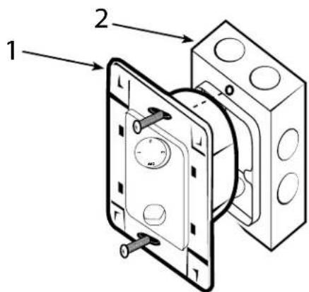
When wiring is complete, make sure no bare wires are exposed from the terminal connections on the back of the fan control unit. Push wiring back into wall outlet box, and secure the wall outlet unit (1) to the outlet box (2) with screws provided
SAA-Bendan LED-Australia-WH18
InStALL WALL COntrOL t0 OutLEt BOX
18
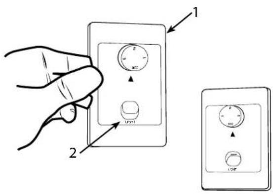
Replace the front cover of the wall control unit by snapping the cover (1) onto the control unit (2).
Turn on the power and check operation of fan. The wall controls the fan speeds as follows: 1 - low; 2 - medium; 3 - high; 4 - off.
Speed settings for warm or cool weather depend on factors such as room size, ceiling height, number of fans and so on. The slide switch controls direction, forward or reverse.
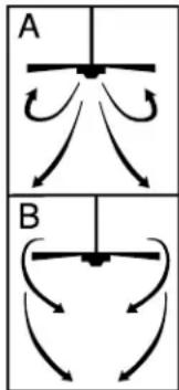
Warm weather/down position - (Forward) Fan turns counterclockwise direction. A downward air flow creates a cooling effect as shown in illustration A.
This allows you to set your air conditioner on a higher temperature setting without affecting your comfort.
Cool weather/up position - (Reverse) Fan turns clockwise direction. An upward airflow moves warm air off the ceiling area as shown in illustration B.
This allows you to set your heating unit on a lower setting without affecting your comfort. (Please however refer to point 10 in Safety Tips when operating in this position.)
NOTE: Turn off and wait for fan to stop before changing the setting of the forward/reverse slide switch.
Maintenance
- Because of the fan's natural movement, some connections may become loose. Check the support connections, brackets, and blade attachments twice a year. Make sure they are secure.
- Clean your fan periodically to help maintain its new appearance over the years. Do not use water when cleaning. This could damage the motor, or the wood, or possibly cause electrical shock.
- Use only a soft brush or lint-free cloth to avoid scratching the finish. The plating is sealed with a lacquer coating to minimize discoloration or tarnishing.
- There is no need to oil your fan. The motor has permanently lubricated bearings.
trOUBLesH00tING GUIDE
If you have difficulty operating your new ceiling fan, it may be the result of incorrect assembly, installation, or wiring. In some cases, these installation errors may be mistaken for defects. If you experience any faults, please check this Troubleshooting chart. If a problem cannot be remedied, please consult with your authorized electrician and do not attempt any electrical repairs yourself.
TROUBLE SUGGESTED REMEDY
| 1. If fan does not start: | 1. Check main and branch circuit fuses or circuit breakers.2. Check wire connections as performed in step #4 of installation.caUtion: Make sure main power is turned off.3. Make sure forward/reverse switch is firmly in up or down position.Fan will not operate when switch is in the middle.4. If the fan still will not start, contact a qualified electrician.Do not attempt to troubleshoot internal electrical connections yourself. |
| 2. If fan sounds noisy: | 1. Check to make sure all screws in motor housing are snug (not over tightened).2. Check to make sure the screws which attach the fan blade holder to the motor are tight.3. Some fan motors are sensitive to signals from Solid State variable speed controls.DO NOT USE a Solid State variable speed control.4. Allow “break-in” period of 24 hours. Most noises associated with a new fan will disappear after this period. |
| 3. If fan wobbles: | All blades are weighed and grouped by weight. Natural woods vary in density which could cause the fan to wobble even though all blades are weight-matched. The following procedures should eliminate most of the wobble. Check for wobble after each step.1. Check that all blades are screwed firmly into blade holders.2. Check that all blade holders are tightened securely to motor.3. Make sure that canopy and mounting bracket are tightened securely to ceiling joist.4. If blade wobble is still noticeable, interchanging two adjacent (side by side) blades can redistribute the weight and possibly result in smoother operation. |
| 4. If light does not work: | 1. Check to see that the wire connections in the switch housing are connected.2. Check for faulty light bulbs.3. If light kit will still not operate, contact a qualified electrician for assistance. |
PARTS LIST
LISTA DE REPUESTOS
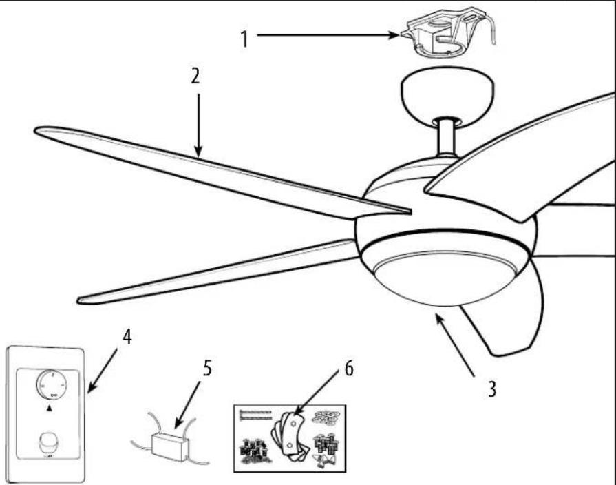
# Description
1....Mounting Bracket
2Blade
3. Glass
4......Wall Control
5.....Capacitor
6. Hardware Pack
SAA-Bendan LED-Australia-WH18
SAA-Bendan LED-Australia-WH18
Westinghouse Lighting, Philadelphia, PA 1029-19154, U.S.A. www.westinghouselighting.com

WESTINGHOUSE, and INNOVATION YOU CAN BE SURE OF
are trademarks of Westinghouse Electric Corporation.
Used under license by Westinghouse Lighting
All rights reserved.
Made in China


AS/NZS Approval No. SAA-181731-EA



- Westinghouse
- OWNER'S MANUAL
- Bendan
- SAFETY TIPS
- READ AND SAVE THESE INSTRUCTIONS
- FeatUres
- PrEPArInG fOr InStALLAtION
- MOUNTInG BrACKEt InStALLAtION
- WlrInG OPtIONs
- MOUNTING
- secUre t0 ceILING
- 7
- BLADE InStALLAt10n
- LIGHT fIXturE InStALLAtION
- rEVErSIBLE SWItCH OPt10n
- WALL COntrOL InStALLAt10n
- WlrInG t0 tHE WALL COntrOL
- OPErAtlOn WALL COntrOL
- InStALL WALL COntrOL tO OutLEt BOX
- InStALL WALL COntrOL t0 OutLEt BOX
- Maintenance
- trOUBLesH00tING GUIDE
- PARTS LIST
- LISTA DE REPUESTOS
- # Description
Brand : WESTINGHOUSE
Model : 7207035
Category : Fan