QCN8082B - Security Camera Q-See - Free user manual and instructions
Find the device manual for free QCN8082B Q-See in PDF.


User questions about QCN8082B Q-See
0 question about this device. Answer the ones you know or ask your own.
Ask a new question about this device
Download the instructions for your Security Camera in PDF format for free! Find your manual QCN8082B - Q-See and take your electronic device back in hand. On this page are published all the documents necessary for the use of your device. QCN8082B by Q-See.
USER MANUAL QCN8082B Q-See
QC IP Camera & NVR Bundle
QUICK START GUIDE
ENGLISH
Welcome
What's Included....3
Understanding Your NVR....4
Get Connected
Registration....5
Connect Your Cameras ....5
Connect NVR to Display....6
Connect Mouse....7
Connect to the Router....8
Powering Up the NVR & Cameras 8
Startup Wizard 9
Setting Up the QC View Mobile App....14
Adding Wi-Fi Cameras....16
QC View On Your Computer
OS X, Mac Users....16
Windows, PC Users 18
Adding Your NVR to QC View....22
Adding Multiple Mobile Devices 25
Understanding the QC System
Playback 26
Backing Up Recordings....29
Get the Most Out of Your Q-See System
Tips on Camera Placement 32
Troubleshooting....34
Glossary....35
Warranty and Support 35
WelcomeTable of Conten
Congratulations on your latest purchase and welcome to the Q-See family. This packet includes everything you will need to help get your smart security system up and running. We are excited to have you on board and thank you for choosing Q-See!
Sincerely,
Priti Sharma
President
Connect with us on social media.


What's Included
Products shown in this section may vary by system
Number of cameras included vary by system
natural_image
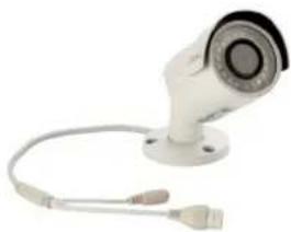
White surveillance camera with attached cable and USB port (no text or symbols visible)100 feet of Network cable per IP camera
natural_image
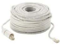
Coiled white cable with two connectors, no visible text or symbolsPower SupplyCameras Camera Network
Your system will include one of the options below
A
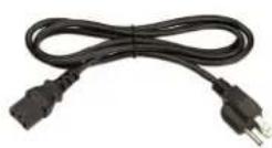
B
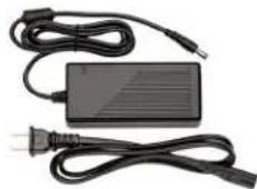
natural_image
Electric charger with black cable and power plug, no visible text or symbolsNVR
Actual NVR will vary by system
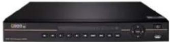
Mouse
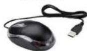
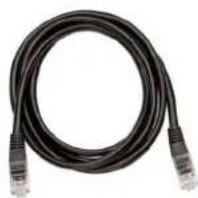
NVR Cables
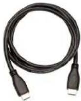
HDMI Cable Network (Ethernet) Cable
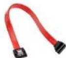
SATA Cable Not included with every system
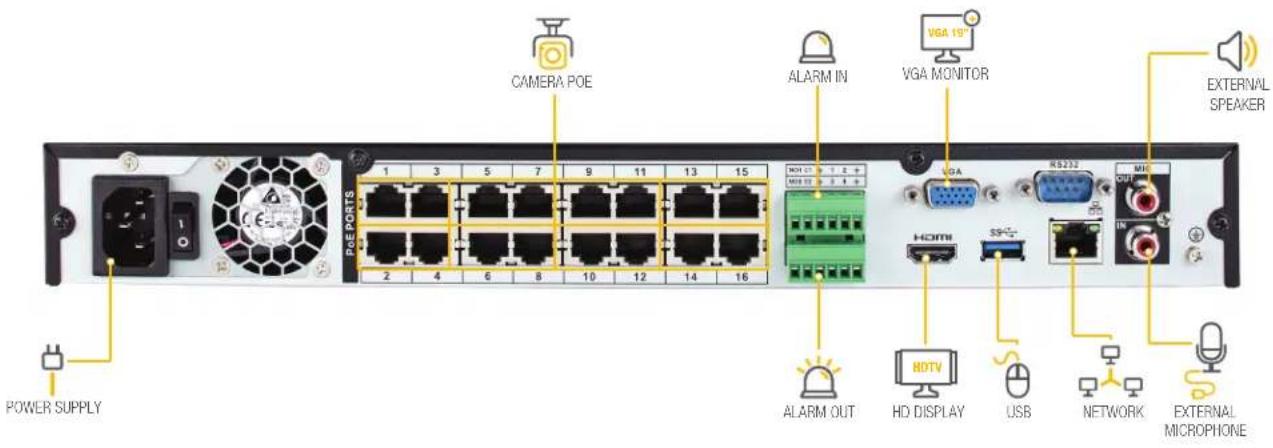
Understanding Your NVR: Rear Panel
NOTE: Connections on the back of your system may vary based on your model.
text_image
CAMERA POE ALARM IN VGA MONITOR EXTERNAL SPEAKER POWER SUPPLY 1 3 5 7 9 11 13 15 PGE PORTS 2 4 6 8 10 12 14 16 HDMI 1 2 + MISI 2 3 4 + LGA RS232 HDMI SP+ HD DISPLAY USB NETWORK EXTERNAL MICROPHONEIMPORTANT: Go through all of the steps to setup and test your system before mounting any cameras or hardware. Always visit www.q-see.com/support to find the most recent guides and up-to-date support for your Q-See products.
Get Connected
Step 1: Registration
Before installing, please register your device on the Q-See Support Portal at www.q-see.com/register to receive critical updates and support for your system. Registering will also help us to assist you with any technical or warranty issues if ever necessary.
Please be sure to keep a record of your model number(s) and to save this guide, as you will need this information if you are ever in need of technical or warranty support.
NOTE: Your username and password used to register your device are not the same as those you use to log in to your system. Please write down your username, password, and model number(s) in the spaces provided below:
Username: ____ Password: ____ Model #: ____
Step 2: Connect Your Cameras
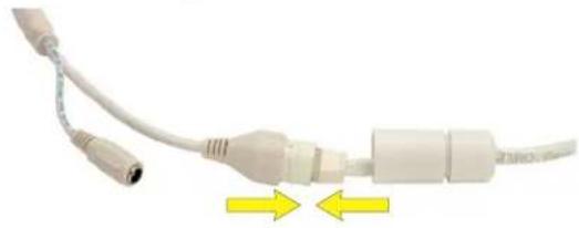
A. Plug the camera network cable into the camera by connecting the Ethernet cable into the camera network port. You should hear a clicking sound as you connect to the port.
natural_image
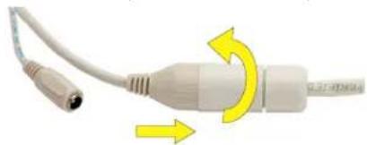
Close-up of a white cable with connectors and two yellow directional arrows indicating movement (no text or symbols)B. Move the white weather-proof housing up and twist to secure the cover over the port. Tighten the base of the cover to complete the weather-proof seal.
natural_image
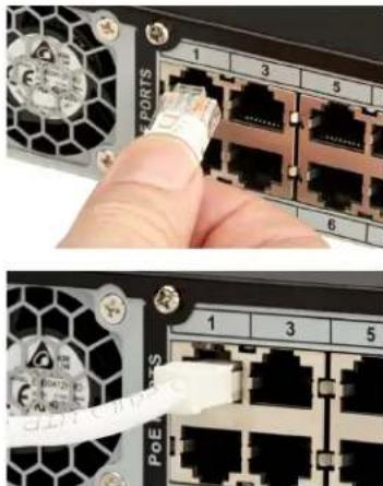
Close-up of a white USB cable with yellow directional arrows indicating rotation or compression (no text or symbols)C. Plug the other end of the camera cable into an available PoE port on the back of your NVR. Again, you will hear a clicking noise when cables are inserted correctly. Repeat steps A through C for each camera.
natural_image
Close-up of a hand inserting a network cable into a server rack (no visible text or symbols)NOTE: Channels are assigned to cameras in the order they are connected. Port numbers do not indicate the channel that will be assigned to the camera.
Step 3: Connect NVR to Display
There are two options to connect the NVR to a display.
Option A: HDMI
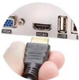
A1. Plug the included HDMI cable into the NVR's HDMI port.
natural_image
Close-up of a hand holding a USB connector with labeled ports (VGA, HDMI, USB) — no additional text or symbols visible.A2. Connect the other end of the HDMI cable to the monitor or TV.
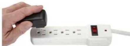
A3. Plug the monitor or TV into a surge protector.
natural_image
Hand holding a black button next to a white power strip with a red LED (no text or symbols visible)Option B: VGA Monitor
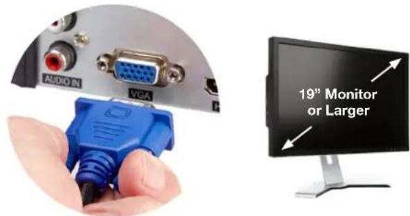
B1. Plug a VGA cable (not included) into the NVR's VGA port. VGA might not support full high definition output.
text_image
AUDIO IN VGA 19" Monitor or LargerB2. Connect the other end of the VGA cable to the monitor. A 19" monitor or larger with 1280 x 1024 resolution is highly recommended.
B3. Plug the monitor into a surge protector.
Step 4: Connect Mouse
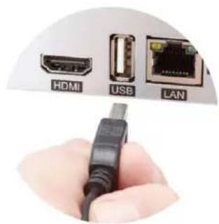
Plug the included mouse into the USB port on the back of the NVR. If your model has two USB ports on the back, either one will work.
text_image
HDMI USB LANStep 5: Connect to the Router
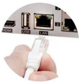
A. Plug the included Network (Ethernet) cable into the Network (LAN) port on the back of the NVR.
natural_image
Close-up of a hand holding an Ethernet cable connector with labeled ports (HDMI, USB, LAN) and ports 1 and 2 visible above.B. Connect the other end of the cable to an open port on your router (not included). You will hear a click when the cable is properly connected.
Step 6: Powering Up the NVR & Cameras
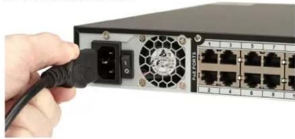
A. Plug the NVR power supply cable into the DC Port on the back of the NVR.
natural_image
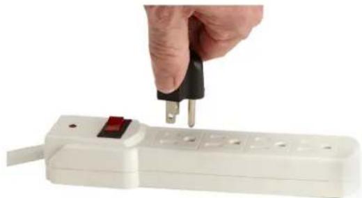
Close-up of a network switch with a black cable inserted, showing port connections and fan interface (no text or symbols visible)B. Plug the NVR power supply cable or power adapter into a surge protector (not included).
natural_image
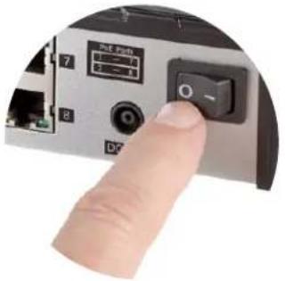
Hand inserting a plug into a white power strip (no text or symbols visible)C. Turn on the NVR's power switch (if present). The NVR may beep as it powers up. The Startup Wizard will appear on-screen after a few minutes.
natural_image
Close-up of a finger pressing a black control switch on a silver device (no visible text or symbols)NOTE: The camera will make a faint clicking sound when the power is activated. The cameras will take about one minute after powering on to begin displaying on the monitor.
DISPLAY COMPATIBILITY: While the system boots, the Q-See logo will appear. If the logo appears on your monitor but goes blank, your display may not be compatible with your NVR. This NVR requires a display capable of supporting 1024 x 768, 1280 x 720, 1280 x 1024, or 1920 x 1080.
Step 7: Startup Wizard
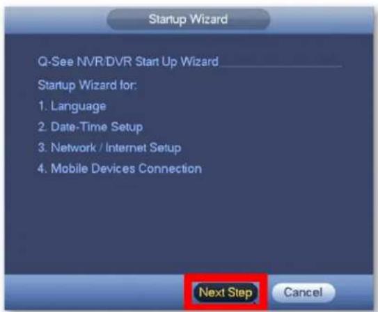
A. In order to effectively use the search functions and maintain accurate recordings, you must complete the Startup Wizard. Click on Next Step to begin.
text_image
Startup Wizard Q-See NVR/DVR Start Up Wizard Startup Wizard for: 1. Language 2. Date-Time Setup 3. Network / Internet Setup 4. Mobile Devices Connection Next Step CancelB. Set the current Date and Time in the screen below and then click Next Step.
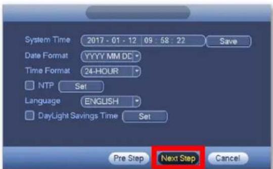
text_image
System Time 2017 - 01 - 12 09 : 58 : 22 Save Date Format YYYY MM DC Time Format 24-HOUR NTP Set Language ENGLISH DayLight Savings Time Set Pre Step Next Step CancelC. Click on EmailSet to add an email address to recover a lost/forgotten password. When you click EmailSet it will ask you for login credentials, use the default username "admin" and default password "admin".
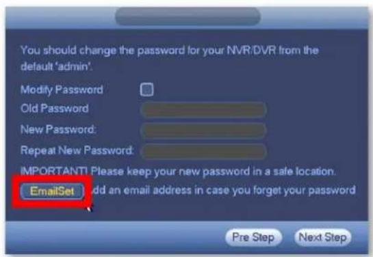
text_image
You should change the password for your NVR/DVR from the default 'admin'. Modify Password Old Password New Password: Repeat New Password: IMPORTANT! Please keep your new password in a safe location. EmailSet Add an email address in case you forget your password Pre Step Next StepD. Enter your email address, select a security question and provide an answer. Click Test and then check the inbox of the email that you entered in the previous step. You should receive an email with the authorization code shortly.
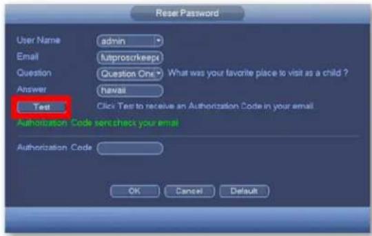
text_image
Reset Password User Name admin Email autproscricks Question Question One What was your favorite place to visit as a child ? Answer hawaii Test Click Test to receive an Authorization Code in your email Authorization Code sent check your email Authorization Code OK Cancel DefaultE. Enter the Authorization Code you received in your email. Click OK.
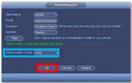
text_image
Reset Password User Name admin Email furoproscricks Question Question One What was your favorite place to visit as a child ? Answer hawaii Test Click Test to receive an Authorization Code in your email. Authorization Code sent check your email Authorization Code 6298 OK Cancel DefaultF. Check Modify Password to change the existing default password which is "admin".
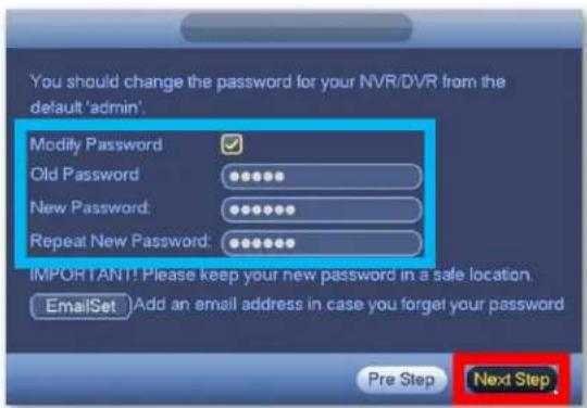
text_image
You should change the password for your NVR/DVR from the default 'admin'. Modify Password Old Password New Password: Repeat New Password: IMPORTANT! Please keep your new password in a safe location. EmailSet Add an email address in case you forget your password Pre Step Next StepPlease write down your new password in the space provided below:
Username: admin
Password:
NOTE: Password is case sensitive and can not exceed eight characters.
G. Click Next Step to start the remote monitoring setup.
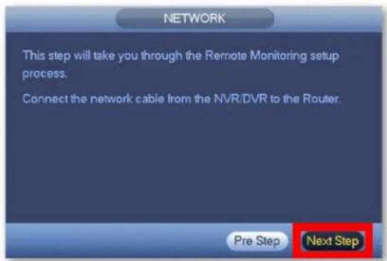
text_image
NETWORK This step will take you through the Remote Monitoring setup process. Connect the network cable from the NVR/DVR to the Router. Pre Step Next StepH. Once the network connection has been successfully established, click Next Step. If the connection is not successful, try powering off the NVR for 30 seconds and going through all of Step 7 again. If this does not work, check www.q-see.com/support for additional troubleshooting.
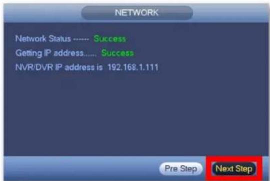
text_image
NETWORK Network Status ...... Success Getting IP address..... Success NVR/DVR IP address is 192.168.1.111 Pre Step Next StepI. Select Local & Internet to connect to your NVR remotely
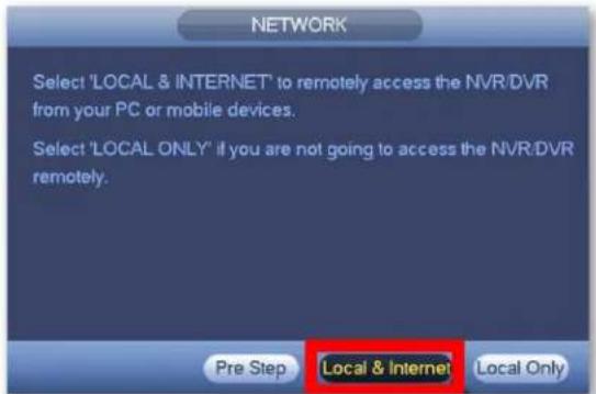
text_image
NETWORK Select 'LOCAL & INTERNET' to remotely access the NVR/DVR from your PC or mobile devices. Select 'LOCAL ONLY' if you are not going to access the NVR/DVR remotely. Pre Step Local & Internet Local OnlyStep 8: Setting Up the QC View Mobile App
Download our free QC View mobile app to your mobile device, available for both Android and iOS.
text_image
QC Download on the App Store GET IT ON Google PlayNOTE: Please do not log in to the app yet.
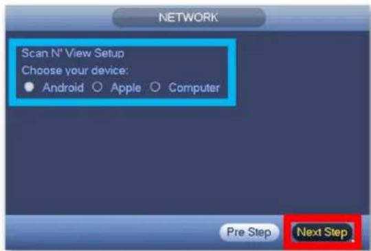
A. Select your desired mobile device in the following window and click Next Step.
text_image
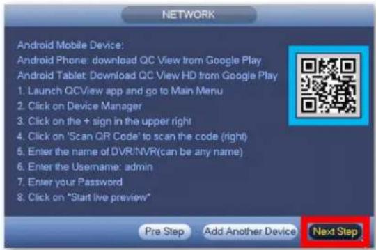
NETWORK Scan N° View Setup Choose your device: • Android ○ Apple ○ Computer Pre Step Next StepB. Follow the steps shown on screen to configure your mobile device and get to the Live Preview screen. After the Live Preview is successful, click Next Step.
text_image
NETWORK Android Mobile Device: Android Phone: download QC View from Google Play Android Tablet: Download QC View HD from Google Play 1. Launch QCView app and go to Main Menu 2. Click on Device Manager 3. Click on the + sign in the upper right 4. Click on 'Scan QR Code' to scan the code (right) 5. Enter the name of DVR/NVR(can be any name) 6. Enter the Username: admin 7. Enter your Password 8. Click on "Start live preview" Pre Step Add Another Device Next Step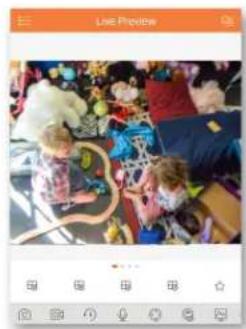
natural_image
Group of children playing with toys in a colorful indoor setting (no visible text or symbols)NOTE: To add multiple mobile devices to your system, first complete the Startup Wizard successfully and then refer to page 25 of this quick start guide.
← Screenshot of Live Preview from the QC View app on iOS.
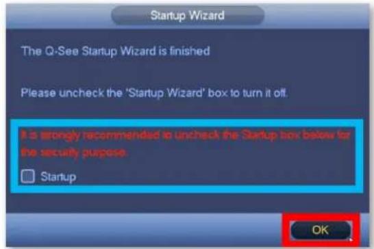
C. The Q-See Startup Wizard is complete. To prevent the wizard from appearing after each reboot, uncheck the Startup box and click OK.
text_image
Startup Wizard The Q-See Startup Wizard is finished Please uncheck the 'Startup Wizard' box to turn it off. It is strongly recommended to uncheck the Startup box below for the security purpose Startup OKNOTE: If the Live Preview is unsuccessful and no camera feed is available, check the Troubleshooting section on page 34 of this guide to verify the camera is receiving power.
Adding Wi-Fi Cameras
If your system includes Wi-Fi cameras or you have purchased Q-See Wi-Fi cameras separately, you should add them to your NVR now. Please reference the Wi-Fi camera quick start guide that was included with your device before proceeding to the next step.
If your system does not involve Wi-Fi cameras then you may proceed to the next section.
NOTE: For information about adding your Wi-Fi cameras to a Wi-Fi network, please visit www.q-see.com/support and reference answer ID 3009. You may also reference answer ID 2812 for information about adding Wi-Fi cameras to your NVR.
QC View On Your Computer
OS X, Mac Users
Step 1
Go to www.q-see.com/support and search for answer ID "2799" to download the latest QC View software. Click the Downloads button and, once fully downloaded, double-click QC View.pkg to open the file.

text_image
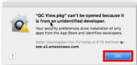
com/app/answers/detail/a Downloads Clear QC View.pkg 10.6 MB of 86.3 MB — 58 seconds remainingNOTE: If during the install process you see a message that the file is from an unidentified developer, click OK and refer to answer ID 2634 at www.q-see.com/support for info on allowing installations from unidentified developers.
text_image
"QC View.pkg" can't be opened because it is from an unidentified developer. Your security preferences allow installation of only apps from the App Store and identified developers. Safari downloaded this file today at 8:13 AM from q-see.s3.amazonaws.com.Step 2
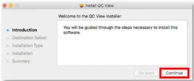
The QC View Installer will appear. Click Continue to proceed with the installation.
text_image
Install QC View Welcome to the QC View Installer: Introduction Destination Select Installation Type Installation Summary You will be guided through the steps necessary to install this software. Go Back ContinueStep 3
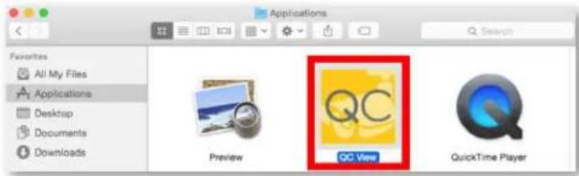
QC View will be located in your Applications Folder. Double-click QC View to launch the app.
text_image
Applications Favorites All My Files Applications Desktop Documents Downloads Preview QC View QuickTime PlayerStep 4
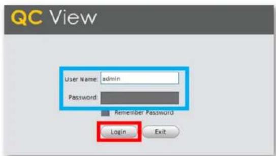
QC View will open to the Login Screen. Enter the default Username & Password below and click Login to continue. These credentials are independent of those used on the NVR.
Username: admin
Password: admin
text_image
QC View User Name: admin Password: Remember Password Login ExitNOTE: Adding the NVR to QC View has been elaborated further on page 22 of this guide.
Windows, PC Users
Step 1
Go to www.q-see.com/support and search for answer ID "2502" to download the latest QC View software.
Internet Explorer Users
Download QC View and click Run.

text_image
Do you want to run or save QCView_Setup.exe (111 MB) from q-see.com? This type of file could harm your computer. Run Save CancelChrome Users
In the Downloads bar at the bottom of the browser window click QCView_Setup.exe to open the file.

Step 2
Proceed with the Installation by clicking Next.
QC View
Welcome to QC View Installation
Fully functional and easily customizable
Fenbix interface 203 main function just a dok anoo.
Group multiple systems and camera according to your needs.
30 of the same functions based on your DVR - and more
We've attended to you
Playback interface based on user feedback.
Export recorded files and clips of the logo while viewing.
multiple search nodes to fit your own.
Laoi Shengme - DC PC-408
Have your computer keep an eye on your system.
Separate alerts in case RV8 or camera is knocked off-line.
Set up separate reporting plans - when solved to compute fast drive.
in the present morning part - 100
More functions to give you interested awareness.
Configure your live home, every year is easy options for you, always and more.

Cancel
Step 3
Review and Accept the License Agreement. Click Next.
QC View
IND-USER LICENSE AGREEMENT("BULY")
The image is too blurry to recognize any text content.
- Period Please and the following agreement clearly defines existing the Software
The third class License Agreement ("EUA") or "Farahamed") is an agreement between you ("You" or "User"), and the Software reader, and the provider ("Provider") of approved services. By installing, copying, downloading or otherwise using the Software the User agrees to be bound by the terms of the Agreement. If YOU DO NOT AGAIN TO THE TERMS OF THIS EUA, YOU MAY NOT USE THE SOFTWARE. Please immediately install, copying, or otherwise using the Software, plus delete any parts of the Software that you have installed or stored.
- The Banknote
Software in the Agreement "Software" means information processing program or supporting file composed of modules or functions units, with supporting files of all or part of source code, direct code and relevant mapes, photos, icons, videos, pound, clock, video records, music, text, code; plus descriptions, functions, features, concepts, quality, tests, user manuals, ELLA and other Participations or electronic version of documents or technical files ("Software Product" or "Software") relevant to the Software of Internet or Provider's products.
You in the Agreement "You" means any individual or individual entity, corporate entity including company, enterprise,
Organization of Section that has obtained license to legal use in the Services. Departmentary Form: In the American "Residential system" means the normal births completion of fair demographic which
Please use to evaluate the Software within its entry.
[Unreadable]
- Software Parts. To the software, you will use the decision. We do not find You the benefits of
(五)利润分配
- Refuse


Step 4
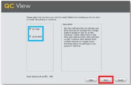
Ensure both QC View and QC PC-NVR are checked.
Click Next.
text_image
QC View Please select the functions you want to install. Delete the modules you do not want to install. Click (Next) to continue. QC View QC PC/MVR Description QC View software lets you manage your DVR, MRV and IP Control from a single point of access on your PC or Max. computer. Watch video feeds in real time, pay tick recorded video and back up files. Combine video streams from multiple systems on a single screen. Remotally adjust the settings on any system in real time. Need Space(Unit as MS): 404 Back Next CancelStep 5
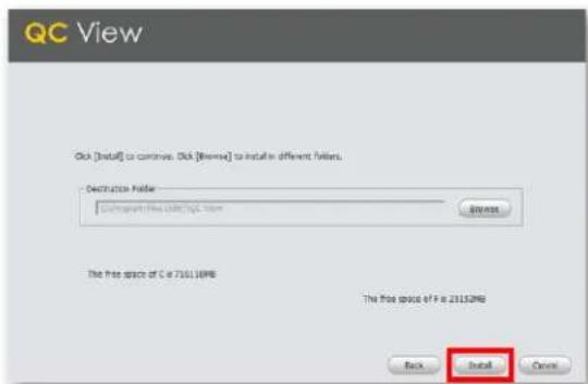
Click Install to begin the installation.
text_image
QC View Click [Install] to continue. Click [Browse] to install in different folders. Destination Folder: Suburban Free Direct Mail Browse The free space of C: 716110MB The free space of F is 21152MB Back Install CancelNOTE: You must have full administrator privileges to install the software on your computer. If you receive any permission errors please contact your system administrator.
Step 6
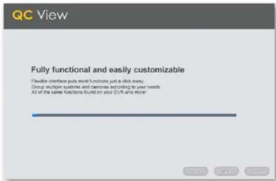
Please be patient, the installation may take a couple of minutes to complete.
text_image
QC View Fully functional and easily customizable Flexible interface puts secret functions just a click away. Group multiple systems and cameras according to your needs All of the same functions found on your DVR and more!Step 7
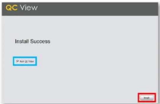
Once completed, ensure Run QC View is checked. Click Finish.
text_image
QC View Install Success IP Run QC View OKStep 8
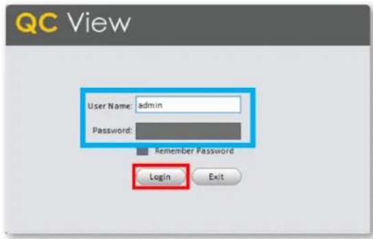
QC View will open to the Login Screen. Enter the default Username and Password listed below and click Login to continue. These credentials are independent of those used on the NVR.
Username: admin
Password: admin
text_image
QC View User Name: admin Password: Remember Password Login ExitAdding Your NVR to QC View
Step 1
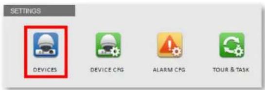
Select Devices from the Home Page.
text_image
SETTINGS DEVICES DEVICE CFG ALARM CFG TOUR & TASKStep 2
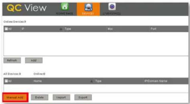
Click Manual Add to add your NVR to QC View.
text_image
QC View HOME PACK DEVICES LIVE TEXTS Online Devices 9 All IP Type Mac Port Refresh Add All Devices 0 Online 0 All Name Type IP Domain Name Manual A-30 Delete Import ExportStep 3
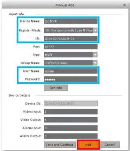
Device Name: Create a new name for your device
Register mode: SN (For a device with Scan N' View)
SN: Enter the device serial number located on the top panel of the NVR
Username: admin (unless changed on page 12)
Password: admin (unless changed on page 12)
Once completed, click Add and then click OK.
text_image
Manual Add Input Info Device Name: QC NVR Register Mode: SN (For device with Scan N View) SN: 2004607AZA3H72 Port: 97777 Type: NVR Group Name: Default Group User Name: admin Password: ****** Get Info Device Details Device SN: 2004607AZA3H72 Video Input: 4 Video Output: 1 Alarm Input: 0 Alarm Output: 0 Save and Continue Add CancelStep 4
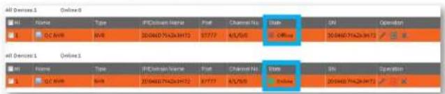
Please be patient, it can take up to 1 minute for the State to change from Offline to Online.
text_image
All Devices 1 Online 0 Name Type IP/Othium Name Post Channel No. Status DN Operation OC NVR NVR 200460754263H72 ST777 KU/5/6 Off-line 200460754263H72 All Devices 1 Online 1 Name Type IP/Othium Name Post Channel No. Status BN Operation OC NVR NVR 200460754263H72 ST777 KU/5/6 Off-line 200460754263H72Step 5
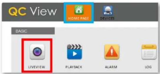
Click the Home Page tab then selectLiveView.
text_image
QC View HOME PAGE DEVICES BASIC LIVEVIEW PLAYBACK ALARM LOGStep 6
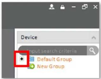
Click the + to display your device(s).
text_image
Device Input search criteria Default Group New GroupStep 7
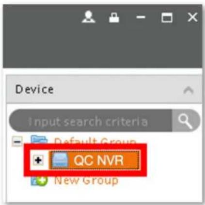
Double click the Device(s) you wish to display.
text_image
Device Input search criteria Default Group QC NVR New GroupStep 8
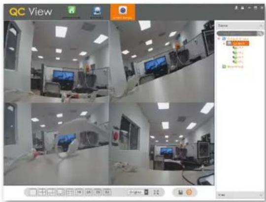
The camera feeds will display automatically.
text_image
QC View View Status 1.00% 2.00% 3.00% 4.00%Adding Multiple Mobile Devices
Step 1
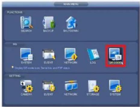
After completing the Startup Wizard, to add additional devices, first download the QC View app on your new device. On the NVR, go to the Main Menu and click QR Code. You will need to reference the steps from the screenshot in Step 8B on page 15 of this guide for mobile setup.
text_image
MAX MENU FUNCTIONS SEARCH BACKUP SHUTDOWN NO SYSTEM EVENT NETWORK LOG OP CODE • Display OS code com Services and PSR data. SETTING CAMERA EVENT NETWORK STORAGE SYSTEMStep 2
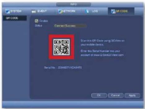
In the screenshot shown on Step 8B on page 15 of this guide, when you reach step 4 (scanning QR code) you can now scan the QR code shown on screen.
text_image
SYSTEM EVENT NETWORK LOG OP CODE OP CODE Under Status Connect Success Start this OFF Clock using iOSView on your mobile device. Enter No Serial Number into your account at www.02.04802View.htm Serial No : 2048071624975 OK Cancel Apply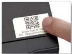
text_image
Q-See Scan IV Version BY: 3M0400PA20000000000000000000000000000000000000000000000000000000000000000000000000000000000NOTE: You can also scan the QR code from the label located on the top of your NVR.
Understanding the QC System
Playback
Step 1
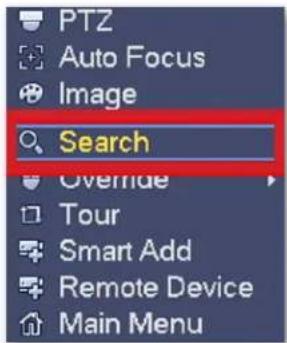
In Live View mode, right-click the mouse to open the Shortcut Menu. Select Search.
text_image
PTZ Auto Focus Image Search Override Tour Smart Add Remote Device Main MenuStep 2
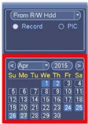
Select the date you want to search using the Calendar. Days with records will appear in Blue.
text_image
From R/W Hdd Record ○ PIC Apr 2015 Su Mo Tu We Th Fr Sa 1 2 3 4 5 6 7 8 9 10 11 12 13 14 15 16 17 18 19 20 21 22 23 24 25 26 27 28 29 30Step 3
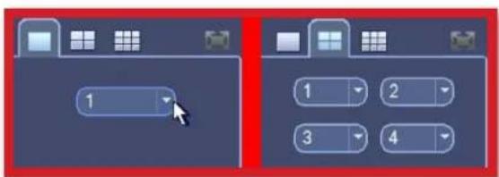
Select the channel(s) you want to view using the "Screen Display Mode".
text_image
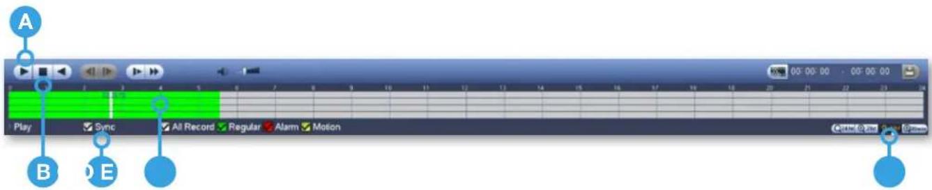
1 1 2 3 4Once you have selected a date, see the next section to explain the various playback controls.
text_image
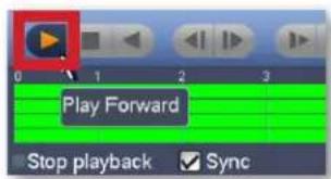
A Play Sync All Record Regular Alarm Motion B D EA. Play
Click Play to start playback from the beginning of the records.
B. Stop
To refine your search (Date & Channels), click Stop.
C. Sync
To playback different times from multiple channels, uncheck Sync.
text_image
Play Forward Stop playback Sync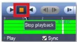
text_image
Stop playback Play Sync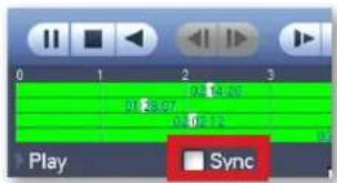
text_image
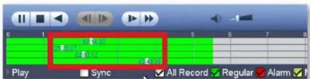
0 1 2 3 01:24:07 02:14:20 02:02:12 Play SyncD. Time Segments
Click the Segments you want to playback for each channel. Playback will begin automatically.
text_image
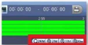
02:14:20 01:5:07 02:02:12 04:31 Play Sync All Record Regular AlarmE. Time Scale
To select a more specific time frame, use the Time Scale and click where to start.
text_image
00:00:00 - 00:00:00 2:55 3 24hr 2hr 1hr 90mBacking Up Recordings
A USB Flash Drive is required to make backups. The steps to do so can be found on our support portal at www.q-see.com/support under answer ID 2542.
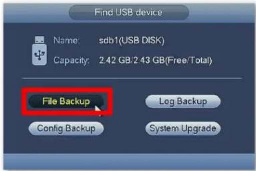
Step 1
Plug a USB Flash Drive into your NVR. A message will appear, click File Backup.
text_image
Find USB device Name: sdb1(USB DISK) Capacity: 2.42 GB/2.43 GB(Free/Total) File Backup Config Backup Log Backup System UpgradeStep 2
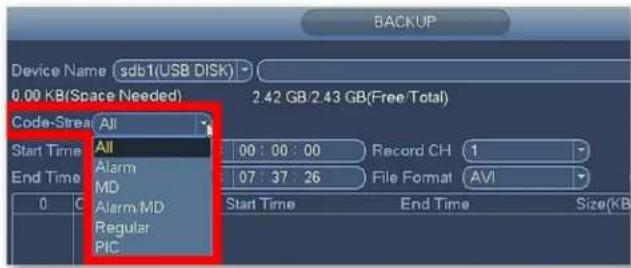
Select the Recording Method you would like to search by selecting from the Code Stream drop down menu.
text_image
Device Name sdb1(USB DISK) 0.00 KB(Space Needed) 2.42 GB/2.43 GB(Free/Total) Code-Stream All Start Time All 00:00:00 Record CH 1 End Time Alarm MD 07:37:26 File Format AVI 0 C Alarm MD Regular PIC Start Time End Time Size(KB)Step 3
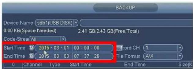
Enter the Start Time and End Time to search.
text_image
Device Name sdb1(USB DISK) 0.00 KB(Space Needed) 2.41 GB/2.43 GB(Free/Total) Code-Stream All Start Time 2015 - 03 - 01 00 : 00 : 00 End Time 2015 - 03 - 03 07 : 37 : 26 0 Channel Type Start Time End Time Size(KStep 4
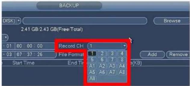
Select the Record Channel to search.
text_image
BACKUP DISK) Browse 2.41 GB/2.43 GB(Free Total) - 01 00 : 00 : 00 - 03 07 : 37 : 26 Record CH 1 File Format Start Time End Time Add Remove 1 2 3 4 5 6 7 8 A1 A2 A3 A4 A5 A6 A7 A8 AllNOTE: Channels starting with "A" are the smaller, lower resolution, versions of the video saved in the corresponding channel.
Step 5
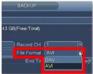
Select the File Format you want the records saved as.
text_image
BACKUP 43 GB(Free/Total) Record CH 1 File Format AVI End Tip DAV AVIDAV: Supports audio, requires playback software download.
AVI: Playable with standard video programs. (Windows Media Player, Quicktime, etc.)
Step 6
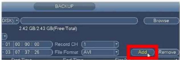
Click Add to display the records.
text_image
BACKUP DISK) Browse 2.42 GB/2.43 GB(Free/Total) - 01 00:00:00 Record CH 1 - 03 07:37:26 File Format AVI Add Remove Start Time End Time SizeStep 7
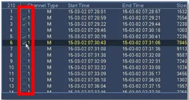
Check the records you want to backup.
text_image
210 Channel Type Start Time End Time Size 1 1 M 15-03-02 07:28:01 15-03-02 07:28:57 1632 2 1 M 15-03-02 07:28:59 15-03-02 07:29:21 7554 3 1 M 15-03-02 07:29:22 15-03-02 07:29:44 7238 4 1 M 15-03-02 07:29:45 15-03-02 07:30:18 1003 5 1 M 15-03-02 07:30:19 15-03-02 07:30:41 7236 6 1 M 15-03-02 07:30:43 15-03-02 07:31:06 7845 7 1 M 15-03-02 07:31:08 15-03-02 07:31:36 9113 8 1 M 15-03-02 07:31:38 15-03-02 07:32:08 9587 9 1 M 15-03-02 07:32:09 15-03-02 07:32:31 7240 10 1 M 15-03-02 07:32:32 15-03-02 07:33:08 1074 11 1 M 15-03-02 07:33:09 15-03-02 07:35:17 3456 12 1 M 15-03-02 07:35:18 15-03-02 07:36:03 1302 13 1 M 15-03-02 07:36:04 15-03-02 07:37:15 1957 14 1 M 15-03-02 07:37:16 15-03-02 07:37:28 7256Step 8
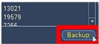
Click Backup.
text_image
13021 19579 7256 BackupNOTE: The length and number of records you choose will impact the time required to complete the backups.
Step 9
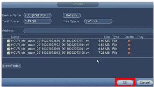
Once complete, the contents of the flash drive will be displayed. Click OK to backup more files or to go back.
text_image
Browse Device Name sdb1(USB DISK) Refresh Total Space 2.43 GB Free Space 2.41 GB Address Name Size Type Delete Play HCVR_ch1_main_20150302072859_20150302072921.avi 6.99 MB File ✗ HCVR_ch1_main_20150302072922_20150302072944.avi 6.69 MB File ✗ HCVR_ch1_main_20150302073019_20150302073041.avi 6.68 MB File ✗ HCVR_ch1_main_20150302073043_20150302073106.avi 7.28 MB File ✗ New Folder OK CancelNOTE: If you wish to backup files using a web browser, visit www.q-see.com/support and search for answer ID 2501.
Get the Most Out of Your Q-See Cameras
Follow these tips to maximize the life and performance of your cameras.
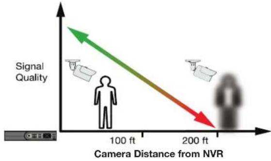
Distance From Viewing/Recording Device
Walls & floors will affect signal strength, especially concrete.
text_image
Signal Quality 100 ft 200 ft Camera Distance from NVRMounting Surface Thickness
Mount your camera on a wall that is at least 2.5" thick.
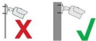
text_image
Diagram showing two methods: a red 'X' symbol and a green checkmark, both with arrows pointing to a container.Avoid direct exposure to weather
Mount your camera under an eave or awning if possible.
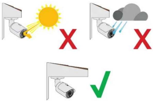
text_image
Safety warning illustration showing three surveillance cameras with sun, cloud, and checkmark indicatorsDo not place camera behind a window
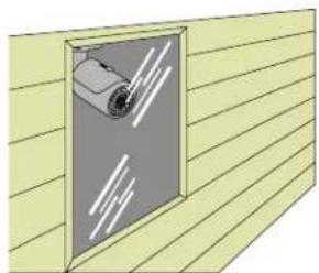
natural_image
Illustration of a door with a mounted device on a wooden surface (no text or symbols)X
Do not place near high-voltage wires or other sources of electrical interference
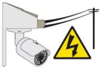
natural_image
Security camera with warning symbol (no text or labels)X
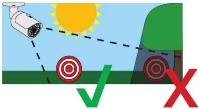
Light levels should be approximately the same between camera and target area
Consistent lighting conditions will provide optimal camera performance.
text_image
Diagram illustrating surveillance camera targeting with sun, target, and X symbols indicating failure or rejection statusLegal Considerations
Always check state and local laws before installing cameras. (2011 NEC 820.44)
Troubleshooting
Testing for Power and Night Vision
After you connect your camera to the NVR and power, if you do not see a video image on screen and your NVR does not display a "video loss" message, you should test your camera to ensure it is properly connected.
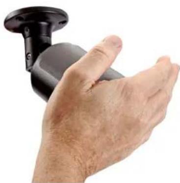
- With your camera(s) still connected to power, cover the lens end of your camera with your hand or an object to completely block it.
natural_image
Close-up of a hand gripping a black cylindrical device (no text or symbols visible)- Keep the lens blocked for 10 seconds. You should see a faint red glow from the infrared LEDs. This indicates that your camera has power and is working properly.
If you still do not have a video signal from the camera, ensure that the camera network cable is properly connected to both the camera and the NVR as shown in Step 2 on page 5.
Other Tests
- Connect the camera to a cable that has a working camera attached. If the camera works, the cable may need to be replaced. Please contact technical support or you can visit www.q-see.com/support for more info.
- Connect the cable to a different channel on the NVR. If you see video, then the culprit is a bad channel input and the NVR may need to be replaced.
Advanced troubleshooting and information is all available on our website at:
www.q-see.com/support
Glossary
IP (Internet Protocol): IP devices communicate with each other via a local network or over the Internet.
Language: This is the language the NVR will use.
Local IP Address: The NVR's address on your local area network (LAN).
NTP (Network Time Protocol): This maintains the accuracy of the NVR's clock.
NVR (Network Video Recorder): IP and Wi-Fi cameras connect to the recorder over the network directly via network (Ethernet) cables.
Warranty & Support
Q-See is always here to answer your questions and take your valued suggestions. Our focus is providing excellent customer support and always working to improve our customers' experience.
Please do not hesitate to call us at 1-877-998-3440 Monday-Friday 6:00 AM - 7:00 PM PST.
Visit www.q-see.com/support for 24/7 support and access to our online Support Portal.
DISCLAIMER: Although Q-See has made every effort to ensure that the information in this guide was correct at the time of printing, Q-See does not assume any liability to any party for any loss, damage, or disruption caused by any errors, omissions, or typos that may occur.
24/7 Online Support Portal and Knowledge Base
www.q-see.com/support

Repairs and Returns

How-To's

Support Videos

Firmware Updates

Software

Manuals and Guides
ADDITIONAL SUPPORT
Live Phone Support
Mon-Fri : 6AM-7:00PM PST
1-877-998-3440
Chat Support
Mon-Fri: 6AM-7PM PST
Sat-Sun 9AM-5PM PST
Languages
English, Spanish