
TruTouch TT-7516UB - Screen Newline - Free user manual and instructions
Find the device manual for free TruTouch TT-7516UB Newline in PDF.


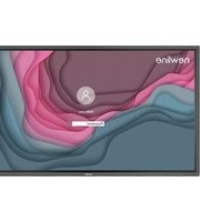
| Product Type | Interactive Touch Screen |
| Brand | Newline |
| Model | TruTouch TT-7516UB |
| Display Technology | LED |
| Aspect Ratio | 16:9 |
| Physical Resolution | 3840 x 2160 (4K UHD) |
| Viewing Angle | 178° |
| LCD Brightness | 370 cd/m² |
| Response Time (Typical) | 8 ms |
| Touch Technology | Infrared |
| Touch Points | 10 |
| Writing Method | Finger or pen |
| Touch Surface Material | Tempered Glass (Anti-Glare optional) |
| Speaker Output | 15 W x 2 (front-facing) |
| Power Consumption (Max) | <350 W (75 inch) |
| Standby Power | ≤0.5 W |
| Working Voltage | AC 100-240 V, 50/60 Hz |
| Input Ports | HDMI x4, VGA, Display Port, USB (Touch, OPS, Android), Microphone |
| Output Ports | HDMI Out, SPDIF, Earphone |
| Control Ports | RS-232, LAN (in/out) |
| ECO Mode | Yes (Standard, Auto, Energy-saving) |
| Child Lock | Yes |
| Remote Boot | Yes (via LAN) |
| Installation | Wall-mounted or floor stand |
| Safety Features | Thermal shutdown, overcurrent protection |
Frequently Asked Questions - TruTouch TT-7516UB Newline
User questions about TruTouch TT-7516UB Newline
0 question about this device. Answer the ones you know or ask your own.
Ask a new question about this device
Download the instructions for your Screen in PDF format for free! Find your manual TruTouch TT-7516UB - Newline and take your electronic device back in hand. On this page are published all the documents necessary for the use of your device. TruTouch TT-7516UB by Newline.
USER MANUAL TruTouch TT-7516UB Newline
Interactive Touch Screen User Manual
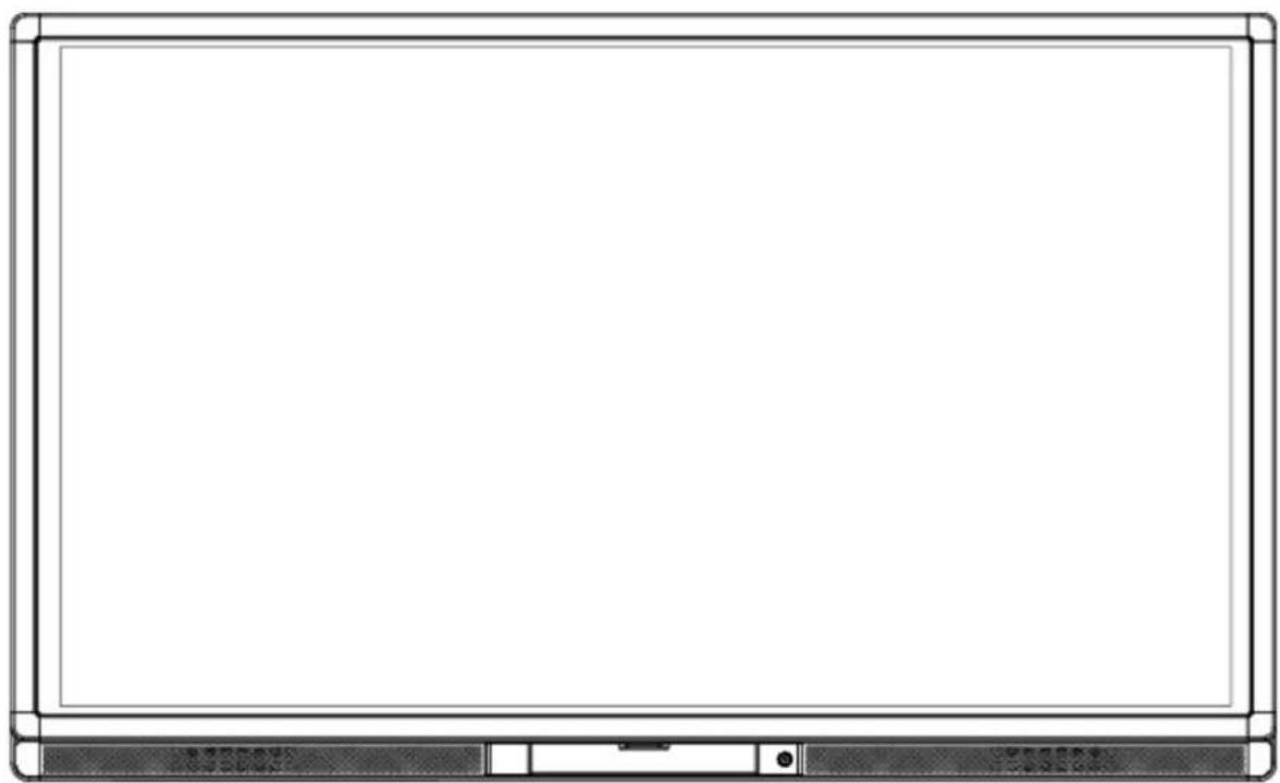
natural_image
Front view of a blank whiteboard with a black tab at the bottom (no text or symbols visible)Welcome:
Thanks for purchasing this product. Please read the instructions carefully before using this product.
This device complies with part 15 of the FCC Rules. Operation is subject to the following two conditions: (1) This device may not cause harmful interference, and (2) this device must accept any interference received, including interference that may cause undesired operation.
NOTE 1: This equipment has been tested and found to comply with the limits for a Class B digital device, pursuant to part 15 of the FCC Rules. These limits are designed to provide reasonable protection against harmful interference in a residential installation. This equipment generates, uses and radiates radio frequency energy and, if not installed and used in accordance with the instructions, may cause harmful interference to radio communications. However, there is no guarantee that interference will not occur in a particular installation. If this equipment does cause harmful interference to radio or television reception, which can be determined by turning the equipment off and on, the user is encouraged to try to correct the interference by one or more of the following measures:
- Reorient or relocate the receiving antenna.
- Increase the separation between the equipment and receiver.
- Connect the equipment into an outlet on a circuit different from that to which the receiver is connected.
- Consult the dealer or an experienced radio/ TV technician for help.
NOTE 2: Any changes or modifications to this unit not expressly approved by the party responsible for compliance could void the user's authority to operate the equipment.
The symbol of the crossed out wheeled bin indicates this product should not be placed in municipal waste. Instead, you need to dispose of the waste equipment by handing it over to a designated collection point for the recycling of waste electrical and electronic equipment.
Contents
Safety Instruction 1
1 Installation Requirement 4
2 Introduction 6
3 Basic Operation 13
3.1 Power on 13
3.2 Power off 15
3.3 Positioning Method for Windows 7 System 16
4 Toolbar Introduction 19
4.1 Task Manager 20
4.2 Whiteboard 21
4.3 Gallery 23
4.4 File Manager 24
4.5 System Settings 25
4.6 Browser 25
4.7 Audio Only 26
4.8 Child Lock Setting 26
4.9 Remote Boot 27
4.10 Disable Android USB Port 29
4.11 Application Programs 29
4.12 Temperature Reminder and Thermal Shutdown 30
5 Signal Source Selection 31
6 Menu 32
7 ECO Mode 35
8 Serial Port Control 36
9 VGA Signal Input 38
10 Multimedia Format Support 39
11 Common Faults and Solutions 40
12 Care and Maintenance 43
13 Technical Parameters 44
Safety Instruction
For your safety, please read the following instruction before you use the product. Serious injury or property loss may be caused by improper operations. Do not try to repair the product by your own.
 WARNING WARNING | |
 | Disconnect the product from power supply immediately if major failures occur.The major failures include the following:Smoke, peculiar smell or abnormal sound is discharged from the product.No image or sound is displayed, or the image error occurs.Where the mains plug or an appliance coupler is used as the disconnect device the disconnect device shall remain readily operable.In the preceding scenarios, do not continue to use the product, disconnect power supply immediately and contact professional staff for troubleshooting. |
| The socket-outlet shall be installed near the equipment and shall be easily accessible. | |
 | Do not drop liquid, metal or combustible into the product.If any liquid or metal is dropped into the product, power off the product and disconnect power supply, then contact professional staff for solutions.Pay attention to the children when they are close to the product. |
| Do not damage the power cable.Do not damage, change, wind, bend, heat or drag the power cable forcibly.Do not put weights (such as the product itself) on the power cable.Do not drag the cable forcibly when you pull out the power plug. If the power cable is damaged, please contact the local distributor to repair or replace it.The power cable in the accessory box is for this product only. Don't use it on other devices. | |
| Put the product on a stable surface.An unstable surface includes and does not limit to an inclined plane, a shaky stand, desk or platform, which might cause the turnover and damage. | |
| Use the battery correctly.Galvanic corrosion, electric leakage and even fire may be caused by improper battery usage.It is recommended to use the designated type of battery and install the battery by correct electrodes (positive and negative electrodes).Do not install and use new battery together with the used one.Take out the battery if the remote control is not used for a long period.Do not expose the battery under overheated environments such as sunlight and firing.Dump the used battery based on local regulations. | |
 | Do not open the cover or change the product by your own.High voltage components are installed in the product. When you open the cover, high voltage, electric shock or other dangerous situations may occur. If inspection, adjustment or maintenance is required, contact the local distributor for help. |
 | Use the specified power supply.Do not use any types of power cables other than the one provided with the product to prevent the product from being damaged.Use a three-wire socket and ensure that it is properly grounded.Pull out the power plug from the socket if the product is not used for a long period. |
| Before you move the product, disconnect all external connections and separate all toppling preventing devices.Move the product carefully to prevent it from being hit or squeezed, especially the screen, which may cause injury if broken. | |
| Clean the dust and metal on the power plug regularly.When you are cleaning, fire or electric shock may be caused if the product is powered on.Keep in mind to pull out the power plug before cleaning it by using a dried cloth. | |
 | Do not put items on the top of the product.Do not put items, such as a container for liquid (a vase, flowerpot, cosmetics or liquid medicine), on the top of the product.If any water or liquid is spilled on the product, short circuit may occur and cause fire or electric shock.Do not tread on the product or hang any items on the product. |
 | Do not install the product in an improper place.Do not install the product in humid places, such as the bathroom, the shower room, the place near windows or outdoor environments where experience rain, snow or other harsh weather. The product installation is also required to avoid a place around by hot spring vapor. The preceding environments may cause faults or electric shock under extreme conditions.Do not put exposed fire source, such as an ignited candle, on the product. |
 | Pull out the power plug during thunderstorms.Do not touch the product when lighting to avoid electric shock.Install or place components which power supply voltage is high enough to cause personal injury in places out of the reach of children. |
 | Do not cover or block up any vents on the product.The overheated components may cause fire, damage the product and shorten the service life.Do not put the venting surface of the product facedown.Do not install the product on a carpet or bed clothes. |
| • Do not use a cloth such as table cloth to cover the product. | |
 | Do not touch the power cable with wet hands to avoid electric shock. Altitude during operation (m): less than 5000m |
CAUTION
 CAUTION CAUTION | |
 | Do not install the product in high temperature environments.Do not install the product near heat source, such as the radiator, the heat reservoir, the stove or other heating devices.Do not expose the product under sunlight, which may cause high temperature and subsequent faults in the product. |
 | For transport:Pack the product for mobility or maintenance by using the cartons and cushioning material provided with the product.Vertically move the product during transport. The screen or other components are easily broken if the product is moved by an improper way. |
 | Keep away from the product when you use a radio.The product design to prevent radio interference complies with the international EMI standard. However, the interference still exists and causes noise in the radio.If noise occurs in the radio, try the following solutions.Adjust the direction of the radio antenna to avoid the interference from the product.Keep the radio away from the product. |
| Advice for watching:Use the product in an environment with comfortable light. It is harmful to your eyes to watch in a too bright or too dark environment.Relax your eyes after a period of time for watching.When you are watching, the distance which is 3 to 7 times of the screen height should be kept, and it is the best distance to protect eyes and prevent eyestrain.Adjust the volume to an appropriate level, especially at night.Use amplifier equipment as the audio input source with caution. If you must use amplifier equipment, the input power should not exceed the maximum of speaker power. Otherwise problems occur, such as the speaker is overpowered and damaged. | |
1 Installation Requirement
BEARING
You can choose the portable or a wall-mounting method according to your needs. The wall mounting can substantially save the space.
If you choose portable mounting, use the mounting rack or support. If you want to use a self-made mounting rack, the bearing capacity of the rack should be at last four times of the screen weight. The bearing capacity of the mounting support must be four times of the actual weight of the screen to ensure steadiness of the interactive touch screen.
When you choose wall mounted, the bearing capacity of the mounting surface must be at least four times of the weight of the screen. When the mounting surface is a wall or ceiling of a building, the wall must be built with solid ricks, concrete or materials of equal intensity. If you need to mount the screen on a loose surface such as an old brick wall, wood plank wall, solid wall, metal or non-metal structure wall or a wall with a thick decoration layer, take necessary consolidating measure to ensure that the screen is steadily mounted.
VENTILATION
| Ventilation requirements | Distance to the surface for installation (cm) | |||
| Nominal power Left | and right sides Top Bottom Back | |||
| Larger than 100 W 1 | 0 20 20 10 | |||

WARNING
If the product is mounting inside a wall or a cabinet, in addition to the preceding requirements, the area of ventilation holes at the bottom, top and two sides must be at least 50% of the sealing surface to ensure proper ventilation.
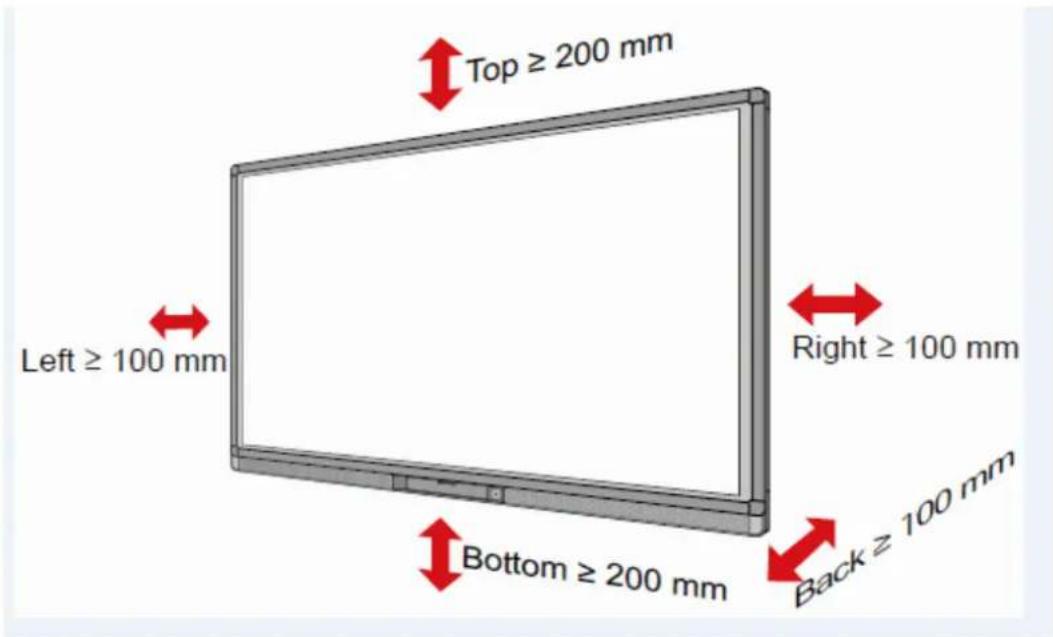
NOTE:
- When you install by wall mounting method, ensure insert the screws into the wall deeper than 10mm.
- Do not block ventilation vents.
• Reference to the CAS132-2006 - The dimension of the 4 bracket mounting holes in the back panel is VESAMIS-Fcompliant (600mm x 400mm for 65" & 70"; 800mm x 400mm for 75" & 80" & 86"). Please use the metric M8 screws with length of 10 to 15 mm to secure the touch screen with the mounting system.
- Please have a professional installer to install the screen.
2 Introduction
Thank you for choosing our interactive touch screen. As our latest independently developed and produced human-machine interactive product, the TRUTOUCH interactive touch screen is a multi-functional display for interactive teaching, digital demonstration, multi-media presentation, touch operations and handwriting. They are well designed and produced to meet the needs of education and corporate applications, and provide a user-friendly experience, digital intelligent control as an ideal equipment for schools and companies. You can use your fingers or opaque objects to write, edit and delete any things on the screen.
The product features are as follows:
•Specially designed for teaching and meeting systems.
- Adopt advanced infrared array scanning and sensing technology, HID driver-free, meaning the product is activated soon after it is powered on.
- Multi-signal sources can be previewed in the window and be switched by touching the screen.
- A special button is set to adjust the brightness automatically with no impact on watching and save up to 50% energy.
- Support front-facing high-power amplifiers.
- When the screen display function is disabled, the product can still play audio to save energy.
- Sense the illumination and brightness automatically to adjust the screen backlight so that the most comfortable screen brightness can be displayed to teachers and students.
Outer Appearance
The front view and back view of the product are displayed as follows.
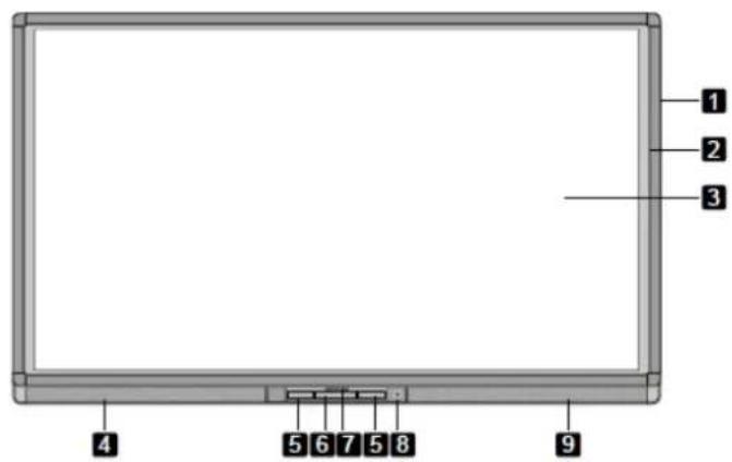
For 65"/70":

For 75"/80"/86":
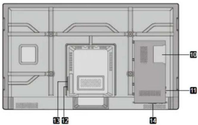
1: Enclosure 2: Infrared Frame 3: Screen 4: Left Loudspeaker
5: Connection Panel 1 6: Control Panel 7: Front Cover Plate* 8: Power on/off
9: Right Loudspeaker 10: OPS Port 11: Convection Panel 2 12: Rocker Switch
13: Power Outlet 14: Connection Panel 3
NOTE: "*" indicates optional.
Control Panel

| Name Fuction | Discription |
| Home Enter/Exit Android home page | |
| Return Return to previous menu | |
| Menu Enter the function menu of screen | |
| ECO Switch among three modes: energy-saving, automatic, and standard. | |
| Source Enter the menu to select the signal source. | |
| Vol - Decrease volume. | |
| Vol + Increase volume | |
| Pc Power Power on or off the OPS. | |
Control Panel 1
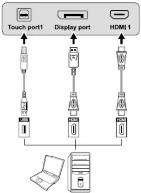
flowchart
graph TD
    A["Touch port1"] --> B["USB"]
    C["Display port"] --> D["HDMI"]
    E["HDMI 1"] --> F["HDMI"]
    B --> G["Computer"]
    D --> G
    F --> G
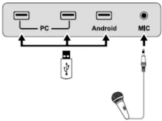
flowchart
graph TD
    A["PC"] --> B["Android"]
    B --> C["MIC"]
    D["USB"] --> A
    E["Microphone"] --> C
| Name Fuction | Discription |
| Touch Port 1 | PC connecting port 1 for touch control. |
| Display Port HD | D digital display port. |
| HDMI 1 | The input terminal 1 for high definition signal, which is used with the Touch Port 1 to operate PC in the way of touch control. |
| PC | The USB 2.0 (Rated output: 5V/0.5A) and USB 3.0 (Rated output: 5V/0.9A) ports for the OPS. |
| Android Android | USB port. |
| MIC | The external microphone port. |
NOTE: Touch Port 1 to HDMI 1, Touch Port 2 to HDMI 2, Touch Port 3 to HDMI 3, Touch Port 4 to HDMI 4 and VGA.
Control Panel 2
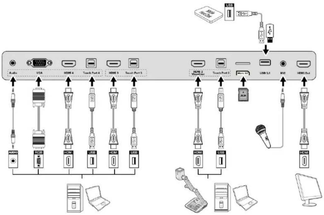
flowchart
graph TD
    A["Audio"] --> B["USB"]
    B --> C["RGB"]
    C --> D["HDMI 4"]
    D --> E["Touch Port 4"]
    E --> F["HDMI 3"]
    F --> G["Touch Port 3"]
    G --> H["USB"]
    H --> I["Micro 10"]
    I --> J["USB 3.0"]
    J --> K["MIC"]
    K --> L["HDMI Out"]
    L --> M["Computer"]
| Name Fuction | Discription |
| Audio Audio input port. | |
| VGA | The VGA port for an external PC, which is used with the Touch Port 4 to operate PC in the way of touch control |
| HDMI 4 | The input terminal 4 for high definition signal, which is used with the Touch Port 4 to operate PC in the way of touch control. |
| Touch Port 4 | The terminal 4 for touch control signal. |
| HDMI 3 | The input terminal 3 for high definition signal, which is used with the Touch Port 3 to operate PC in the way of touch control. |
| HDMI 2 Visualizer | The input terminal 2 for high definition signal, which is used with the Touch Port 2 to operate PC or Visualizer in the way of touch control.Note:Connect a visualizer for touch screen control function and HD display mode; please use the HDMI 2 Visualizer port. |
| Touch Port 2 | The USB terminal 2 for touch control signal. |
| Micro SD The external port for the micro SD card. | |
| USB 3.0 The port for USB 3.0. | |
| MIC The external microphone port. | |
| HDMI Out | The output terminal for high definition signal, which can transmit the signal to other display equipment with high definition.Note:This port may not be present depending on the model. |
Control Panel 3
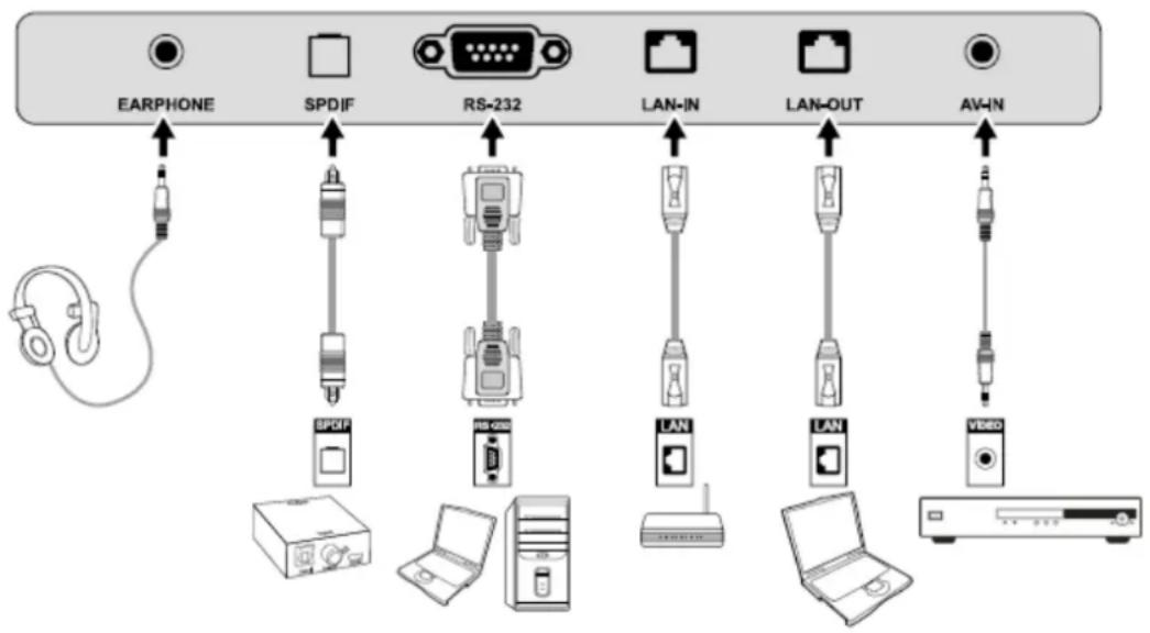
flowchart
graph TD
    A["EARPHONE"] --> B["SPDIF"]
    B --> C["RS-232"]
    C --> D["LAN-IN"]
    C --> E["LAN-OUT"]
    C --> F["AV-IN"]
    G["耳机"] --> A
    H["PCB"] --> I["PCB"]
    J["PCB"] --> K["PCB"]
    L["PCB"] --> M["PCB"]
    N["PCB"] --> O["PCB"]
    P["PCB"] --> Q["PCB"]
    R["PCB"] --> S["PCB"]
    T["PCB"] --> U["PCB"]
    V["PCB"] --> W["PCB"]
    X["PCB"] --> Y["PCB"]
| Name Fuction | Discription |
| EARPHONE The port for earphone. | |
| SPDIF Audio digital output port | |
| RS-232 | The input port for series signals, which is used by specific control device of serial port to input serial port protocol in order to control the screen. |
| LAN-IN The input port for local area network. | |
| LAN-OUT The output port for local area network. | |
| AV-IN Audio and video signal input port. | |
NOTE:
- Pleaseusethecableprovidedwiththeproducttoconnecttodevice.
- HDMI1,HDMI2,HDMI3andHDMI4arehigh-definitionmultimediaports,whichareusedto provide home theatre experience with the best quality for consumers by transmitting high-definition, all-digital audio and video. If there is an HDMI port on the external device, you are advised to connect it with the product by using the HDMI cable in order to display better image and sound effect.
Functions of the Remote Controller
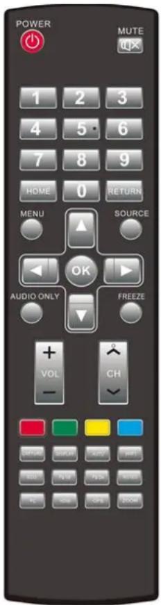
| Image Fuction Discription | |
| On or standby | |
| Mute | |
| 0-9 Select TV channel or enter number | |
| Open the Android home page | |
| Go back or return to the parent menu. | |
| Show or hide munu | |
| Show or exit from the list of signal sources. | |
| Enable audio only mode. | |
| Freeze | |
| Up/Down/Left/Right direction buttons | |
| Confirm. | |
| Capture screen shots. | |
| Show the current signal source. You cannot show it in Android. | |
| Adjust screen displaying. | |
| Open WIFI on the computer. | |
| Change the display mode. | |
| Switch to the previous page on whiteboard software and PPT. | |
| Switch to the next page on whiteboard software and PPT. | |
| Open whiteboard software. | |
| Switch over to VGA signal source. | |
| Switch over to HDMI signal source. | |
| Switch over to OPS signal source. | |
| Zoom in and out. | |
Instructions of Remote Controller
The effective area of the remote controller includes the vertical distance within five meters in front of the product, and the area within an angle of 30 degrees from the vertical point to the left and the right.
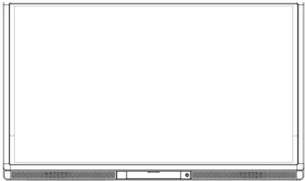
natural_image
Blank whiteboard with a gray tab at the bottom (no text or symbols visible)The effective receiving area is about 3 meters with 30° angle from vertical point to the left.
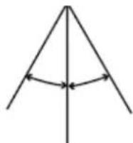
The effective receiving area is about 3 meters with 30° angle from vertical point to the right.
The effective receiving distance is about 5 meters from the front of device.

WARNING
To avoid probable faults, please read the following instructions and use the remote controller properly.
- Do not drop or beat the remote controller.
- Do not spill water or other liquid on the remote controller.
- Do not put the remote controller on wet items.
- Do not expose the remote controller under sunlight or put it near overheated source.
3 Basic Operation
3.1 Power on
Step 1 Turn on the interactive touch screen with the 100V-240V 50Hz/60Hz AC power supply. The power cord should be completely plugged into the power outlet, and insert the power connector into the appliance couplers at the bottom side. The power current must be grounded.
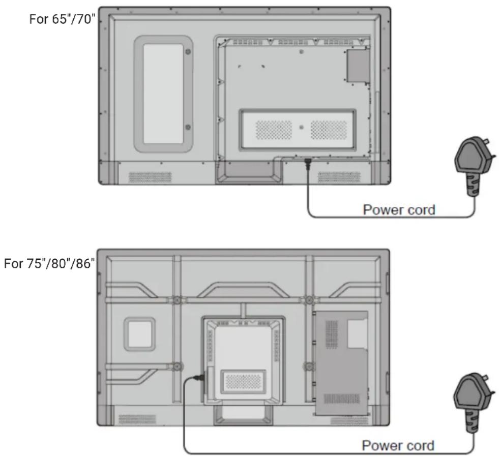
Step 2 Connect the screen to the power supply. Switch on the rocker switch (on the right bottom of the rear of the screen, next to the power port) to enter the standby status. The power indicator turns red.
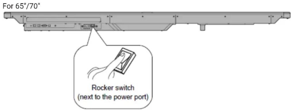
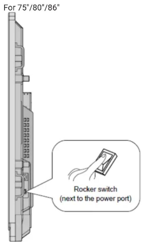
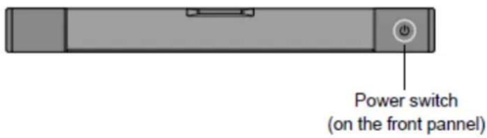
Step 3 Press power switch on the control panel or Power on the remote controller to turn on the interactive touch screen. The OPS is boot. The power indicator turns green.
3.2 Power off
Step 1 Press PC Power to turn off the OPS (for all-in-one models only).

Step 2 Press Power on the control panel or Power on the remote controller to enter the standby mode. The screen will show the following information.
Please turn off PC before shutting down. To shut down completely, press power again.
Step 3 Press Power on the control panel or Power on the remote controller to confirm and pass to the Standby mode. The power indicator turns red.
Step 4 In the standby mode, switch off the rocker switch to turn off the interactive touch screen.

WARNING
- Please turn off the OPS before you turn off the interactive touch screen. Otherwise, the computer may be damaged.
- Disconnect the interactive touch screen from power after the screen enters standby mode. Otherwise, the screen may be damaged. A sudden power failure may damage the interactive touch screen.
- Frequent power on and off in a short time may cause faults.
Status of the power indicator is as follows:
| Power indicator Status | |
| No light Powered off | |
| Red Standby | |
| Green Powered off |
3.3 Positioning Method for Window 7 System
Step 1 Connect the interactive display to PC using the USB cable via the USB interface on the panel.
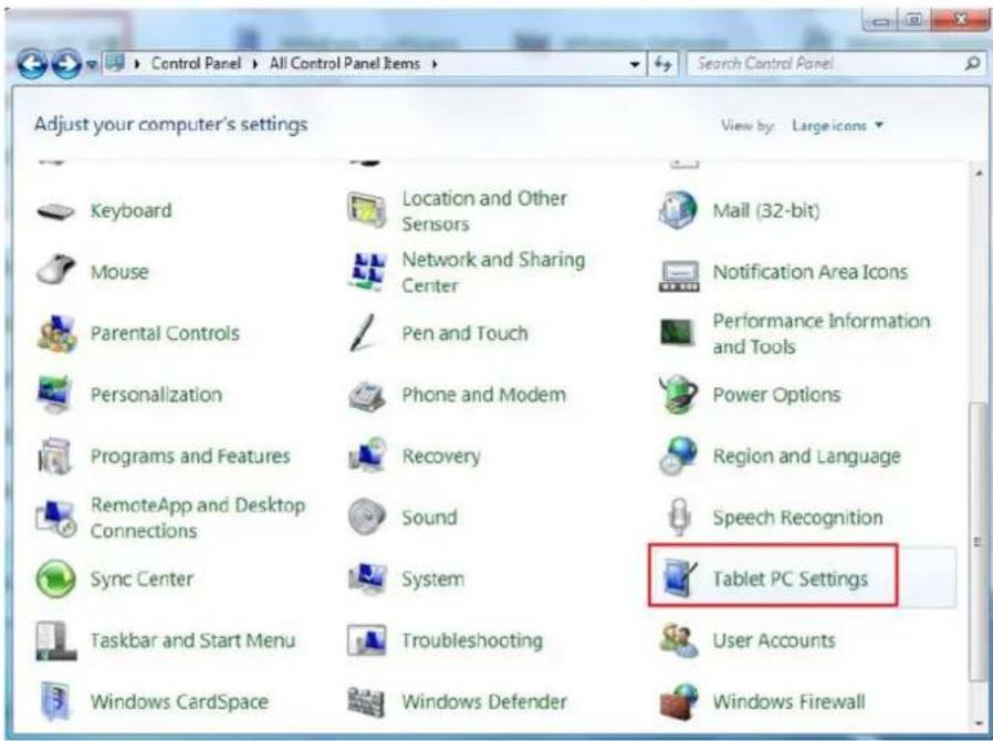
Step 2 Choose Control Panel > Tablet PC Settings.
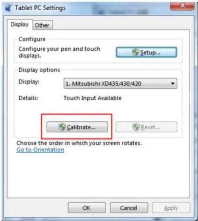
Step 3 Click Calibrate in Tablet PC Settings window.
Step 4 Use the pen to click and hold the center of the flickering cross. Do not release it until the flickering cross moves to the next point. Repeat and complete the positioning process according to instructions on the interface.
| To provide calibration samples, tap the crosshair each time that it appears on the screen. Right-click anywhere on the screen to return to the last calibration point. Press the Esc button to close the tool. Do not change your screen orientation until you have completed the calibration process. | |
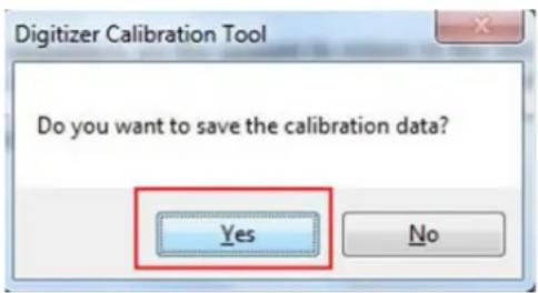
Step 5 Click Yes after the calibration is completed.
TIP
- Toensurethehandwritingaccuracy, usethepenprovidedtogetherwiththeinteractivedisplay rather than a finger to perform calibration.
- Positioningerrorsmaycausetouchfunctionfailureontheinteractivedisplay.Inthiscase,youneed to perform positioning one more time.
- During the positioning process, you can press ESConthekeyboardtoexit the positioning operation.
- The positioning interface varies between different software versions. Please follow the actual instructions provided on the interface.
3.4 OPS Installation

WARNING
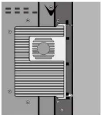
The OPS does not support hot-plugging. Please insert the plug of the OPS after the interactive touch screen is disconnected from the power.
Install the OPS by the following steps:
Step 1 Insert the OPS into the special slot on the rear of the interactive touch screen.
Step 2 Tighten the screws.
Step 3 Confirm the OPS installed correctly.
natural_image
Pure electrical circuit lines without any symbols4 Toolbar Introduction
The toolbar has three modes: Home Page, Task Manager, and Whiteboard.
Under any of the three modes, you can click on the toolbar to go back to the previous page and click to exit from other programs or go back to the home page from other signal sources.
- On the home page, the toolbar is under home page mode and shows icons of the task manager, signal source, white board, input signal, file manager, system setting, browser and search engine. You can click an icon to open the corresponding program.

natural_image
Green background toolbar with icons for home, document, folder, printer, globe, and grid (no text or symbols)- After the whiteboard program is started, the toolbar enters the whiteboard mode, in which you can choose a pen, line weight and color to write on the whiteboard.
- If you want to use the whiteboard function with non-signal model, Click on the displayed menu, the New Page, Overview, Delete All and Settings functions are listed.
- If you want to use whiteboard function with signal model, please click the icon to enter the menu setting interface.


natural_image
Toolbar with icons for home, gear, camera, and email (no text or symbols)- In programs other than the whiteboard, the toolbar is in the Remarks mode. You can select a pen, line weight and color to write and add remarks on the opened file (including image, PPT and PDF). Click on the right to hide the toolbar. Scroll up with your finger to display the toolbar.

4.1 Task Manager
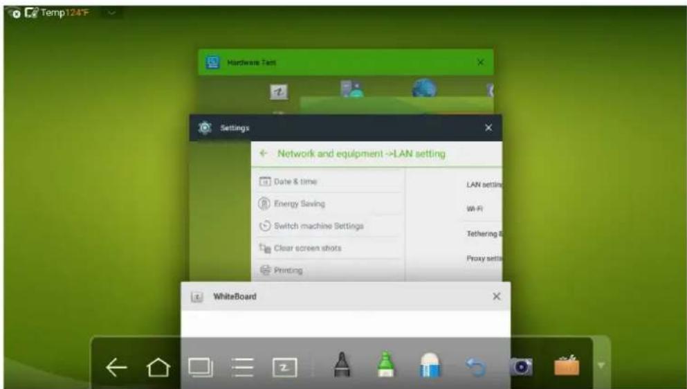
In the task manager, you can view current running programs, switch and end programs. Click to enter the task manager as shown in the following figure:
View Running Programs
In the task manager, scroll up and down to view the current running programs.
Switch Programs
In the task manger, click an application program icon to switch programs. For example, click Settings to switch to the system setting application program, or click Browser to switch to the browser application program.
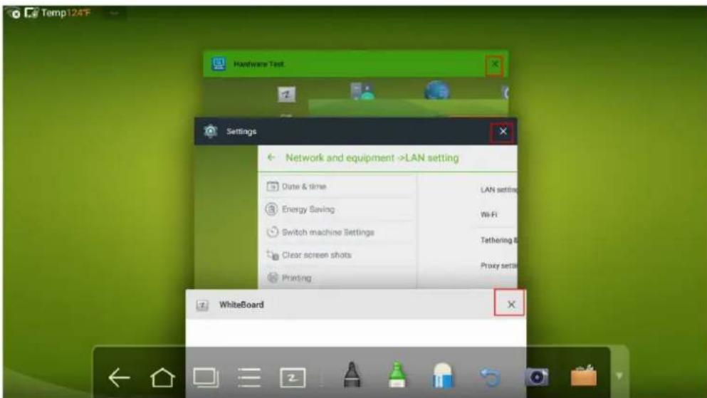
End Programs
In the task manager, select a program, click the ✗ icon of top right corner or scroll right or left to end the program.
4.2 Whiteboard
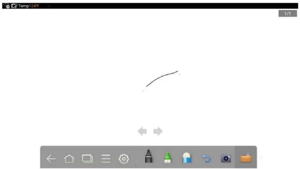
The whiteboard provides the writing function. In the whiteboard program, you can select a pen, line and color to write and use an eraser to erase content on the whiteboard. You can also print and clear the content on the whiteboard.
Click z on the toolbar or press Whiteboard on the remote controller to enter the whiteboard interface.
natural_image
Simple line drawing of a curved line with directional arrows, displayed in a software interface (no text or symbols on the line itself)New Whiteboard and Settings
Click 📋 in the displayed menu, the functions of New Page, Overview, Delete All and Settings are listed.
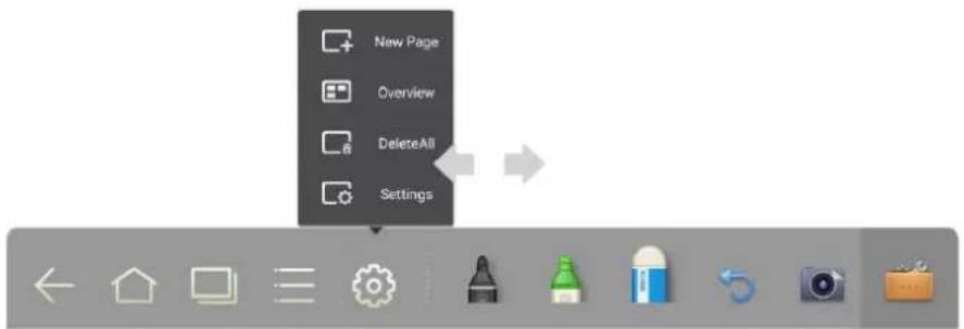
Click Settings to set the color and shade of the whiteboard, as shown in the following figure:
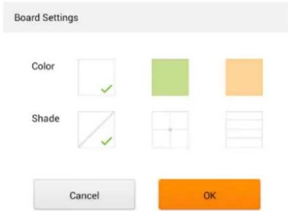
-21-
Pen, Line Weight and Color
If the marker is selected, click and hold ⚠ for two seconds to set its line weight and color.
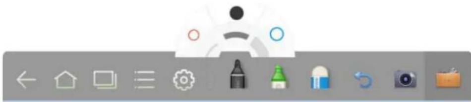
natural_image
Toolbar with icons for home, home, home, gear, camera, and email (no text or symbols on icons)If the highlighter is selected, click and hold 📄 for two seconds to set its line weight and color.
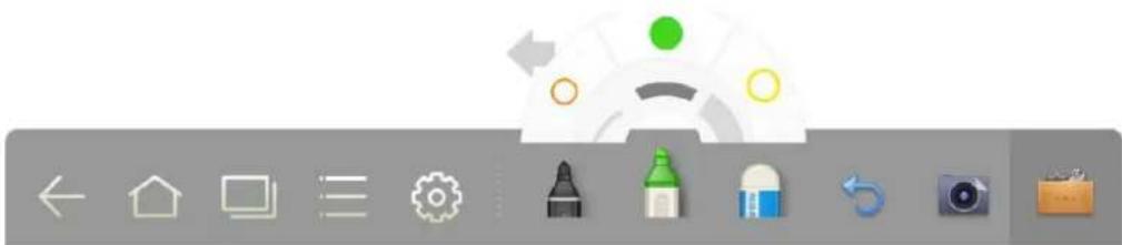
natural_image
Toolbar with icons for home, home, window, gear, and camera (no text or symbols)Eraser
Two methods are available to erase written errors or content as follows:
- Click to select the eraser, and then you can use it to erase the content on the whiteboard.
- Use five fingers to touch the screen and a circle is displayed indicating the scope for erasing. Move the circle to erase the content you wrote.

Cancel
Click ↻ to cancel operations.
Screen Capture
The following two methods are used to capture screen:
- Click to Capture current content on the whiteboard and save it as an image in Screenshots directory. (The toolbar is not captured in the image.)
- Press CAPTURE on the remote controller to save current content on the whiteboard as an image in Pictures > Screenshots directory in the file manager.
You can open the directory by two ways:
- Go back to the home page and click 📋 on the toolbar to enter the file manager. In the system file, find and click the Screenshots folder to check.
- Click n application programs to enter the image browsing interface. In the system file, find and click the Screenshots folder to check.
Print, Clear and Freeze Screen
Click 📄, Print, Clear and Freeze screen are displayed. Click Print to print current content on the whiteboard. Click Clear to clear all current content on the whiteboard. Click Freeze screen to capture the current screen and can do zoom in, zoom out, annotation on the freeze screen.
4.3 Gallery
You can enter the gallery to view images one by one or play them as slides.
Click 📋 in the application programs to enter the gallery. All folders containing images are displayed.
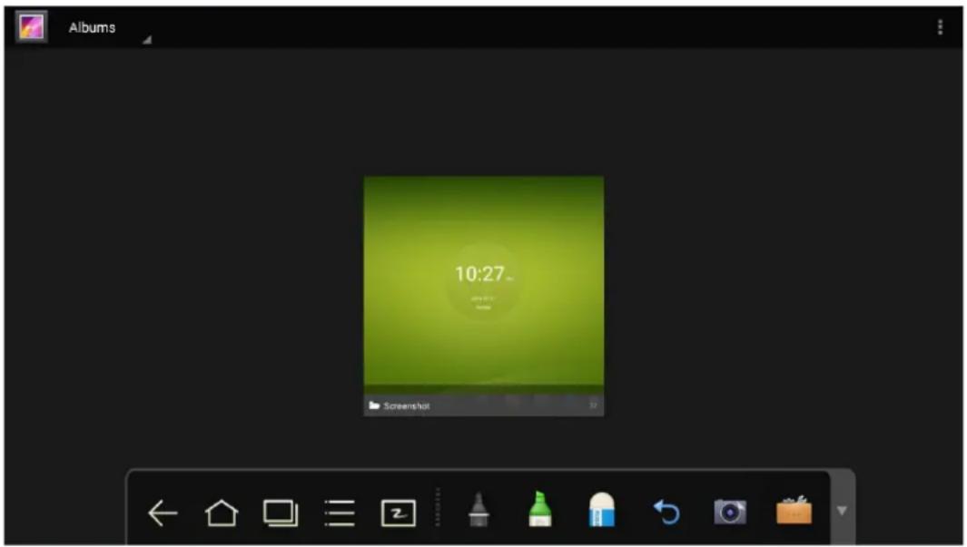
•Full preview
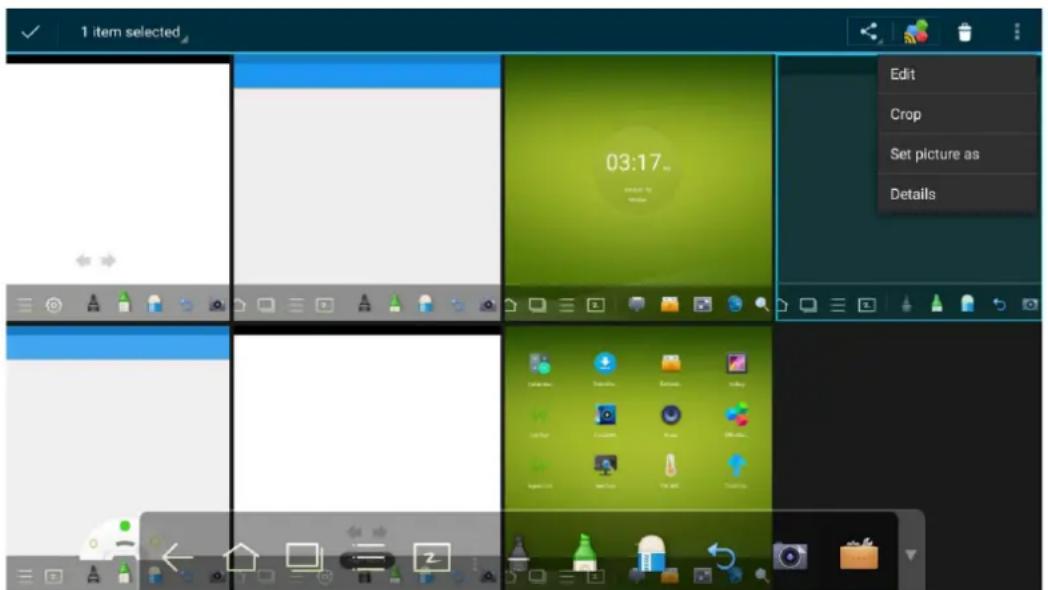
One full screen can maximum display eight images, you can preview other group image by your finger slipping left or right. Using long press on screen to select multiple images, and then you can click icon on the upper right corner to print, share, delete, edit, set and view detail of selected images.
-23-
•View images one by one
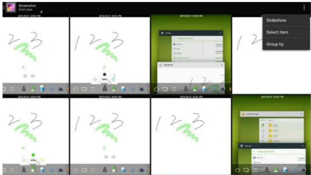
Click one image in a folder. Scroll left to show the previous image and scroll right to show the next image.
- Play slides
Click on the upper right corner of the folder and select Slideshow to play images as slides.
4.4 File Manage
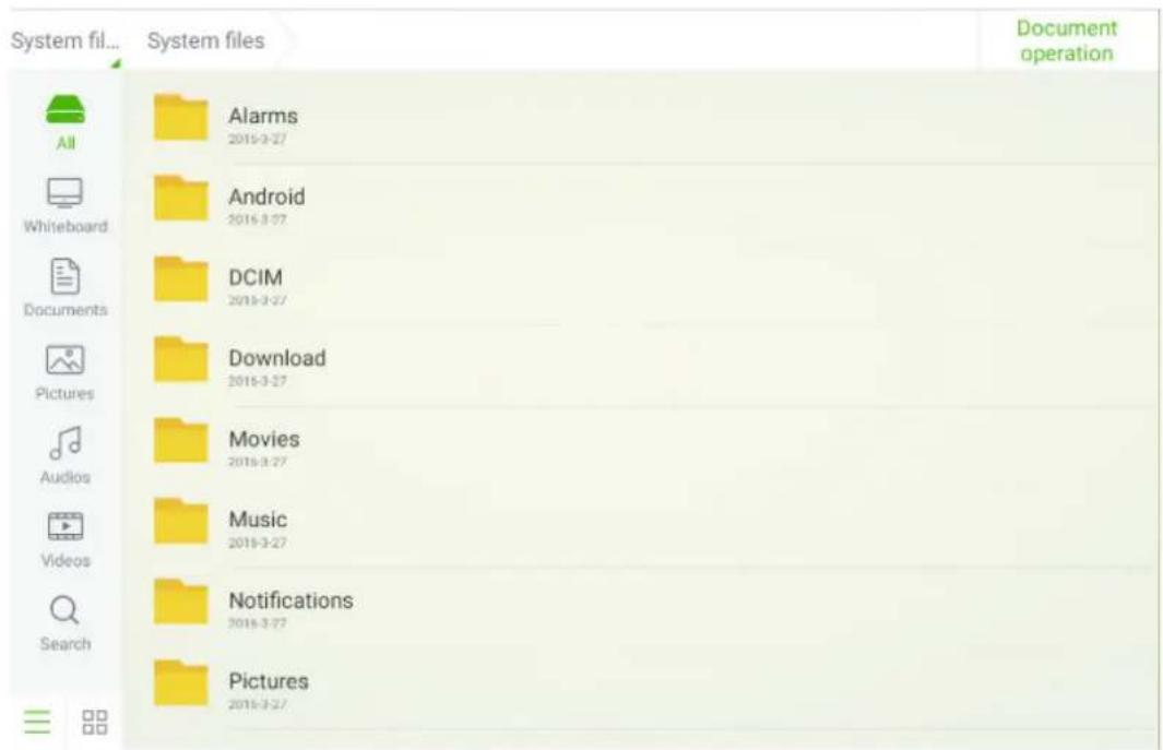
Click 📄 on the toolbar to enter the file manager interface. Current system files are displayed. External device files are also displayed, such as the files in the SD card and USB drive. The file manager provides various functions, such as preview, filter, search, select, copy and delete files.
4.5 System Settings
Click 📄 on the toolbar to enter the system settings interface. The Network, Apps, Language & input, Date & time, Energy Saving Setup, Power on/off Settings, Clear screen shots, Printing, Authorization setting, Smart eye protection, Input Source setting, Background setting and About are displayed on the screen. You can click the items to have your preferred system setting. Click the area outside of the system settings interface to exit.
| ← Network | |
| Network | LAN setting |
| Apps | Wi-Fi |
| Language & input | Tethering & portable hotspot |
| Date & time | Proxy Settings |
| Energy Saving Setup | |
| Power on/off setting | |
| Clear screen shots | |
| Printing | |
| Authorization setting | |
| Smart eye protection | |
| Input Source setting | |
| Background setting | |
| About | |
4.6 Browser
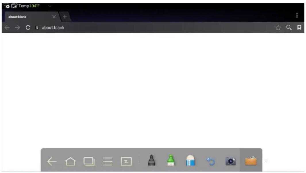
Click 📄 on the toolbar to open the web browser. Enter a website in the address bar and enter keywords in the search box by using the soft keyboard or remote controller.
4.7 Audio Only
Press AUDIO ONLY on the remote controller to turn off the screen but keep audio on. To turn on screen again, touch any place on screen or click AUDIO ONLY again to return to normal operation mode.
4.8 Child Lock Setting
You can turn on/off Child Lock Setting function by three methods below:
- Click on the toolbar to enter the system settings interface. You can click the Authorization setting item to turn on the Child Lock function.
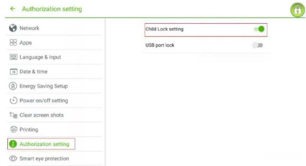
- Press ECO button on the front panel for more than 5 seconds to enter Child Lock mode. Under Child Lock mode, press ECO for more than 5 seconds again to unlock. - Press ECO button on the remote controller for more than 5 seconds to enter Child Lock mode. Under Child Lock mode, press ECO for more than 5 seconds again to unlock.
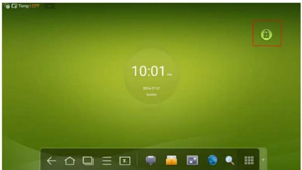
An icon will show on the top-right corner of the touch screen, as seen in the following figure, if the device is under Child Lock mode.
4.9 Remote Boot
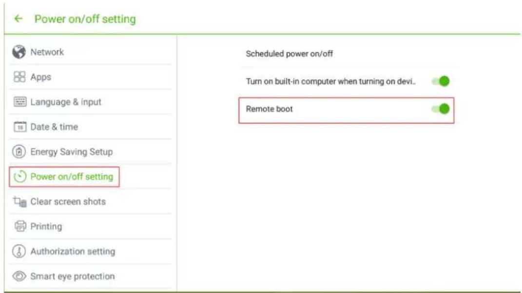
Click 📄 on the toolbar to enter the system settings interface. You can click the Power on/off setting item to turn on the remote boot function. The administrator of control center can send requests via LAN using MAC address of touch screen to power on touch screen remotely.
To use the function successfully, touch screen should be power off and connected to control center with LAN cable in the same network.
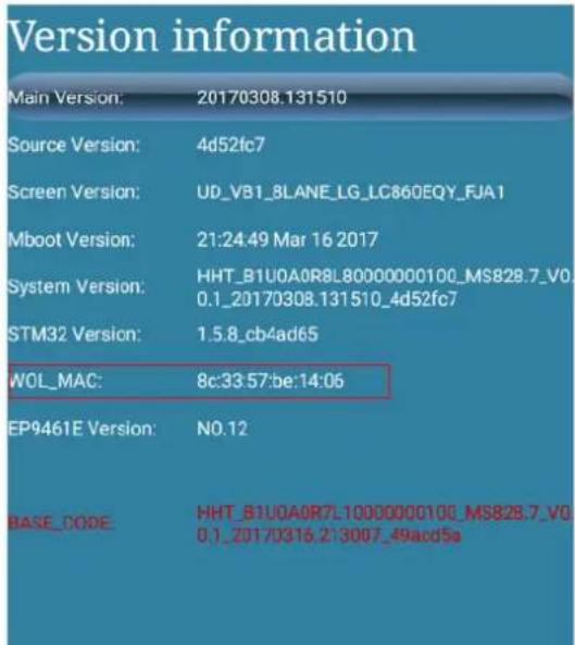
Steps of obtaining MAC address of touch screen:
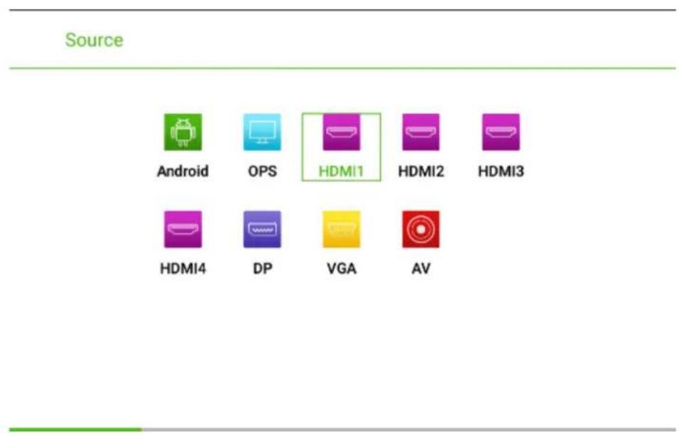
Step 1 Using "SOURCE" on the remote control or "Source" on the front control panel of touch screen to enter Source page.
Step 2 Using remote control to enter number "2580" in input signal page to enter "Design Menu" page.
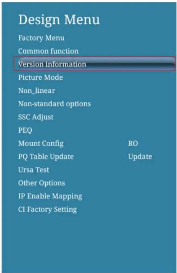
Step 3 Click "Version information" in "Design Menu" page to enter "Version information" page and get "WOL_MAC" as MAC address of touch screen.
4.10 Disable Android USB Port
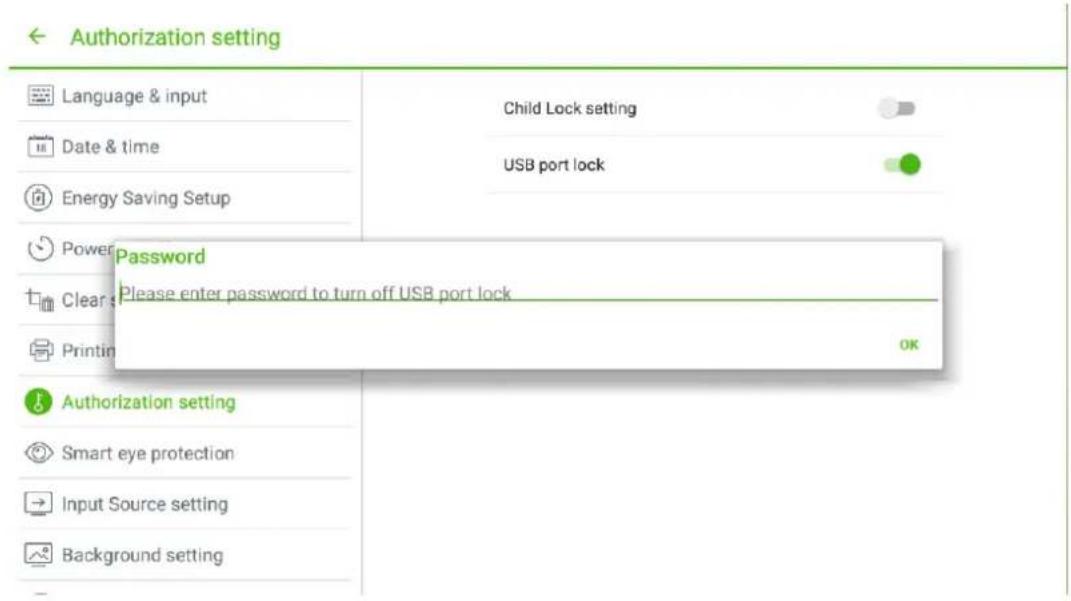
Step 1 Click 📋 on the toolbar to enter the system setting interface. You can click the Authorization setting item to turn on USB port lock function.
Step 2 Once turn on this function, all the USB ports of Android will be disabled.
Step 3 To turn off this function, enter pin code "888888".
4.11 Application Programs
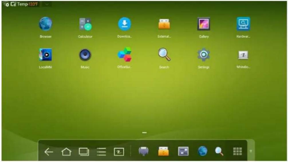
Click 📁 on the toolbar to enter the application program page. All application programs in the system are displayed. Scroll right and left to turn the page, as shown in the following figure:
Calculator
Click to enter the calculator application. Click digits and operators on the keyboard to perform calculation.
| 7 | 8 | 9 | ÷ | DEL | sin | cos | tan |
| 4 | 5 | 6 | × | In | log | ! | |
| 1 | 2 | 3 | - | π | e | ^ | |
| . | 0 | + | = | ( | ) | √ |
Music
Click 🔒 to start the music program. The music in the local disk is displayed by artists, albums, songs, playlist and playing status.
4.12 Temperature Reminder and Thermal Shutdown
Temperature Reminder
The real-time temperature of the interactive touch screen is displayed on upper left corner of the home page. Click the temperature display area on the top-left corner of screen to switch between Celsius and Fahrenheit.
Thermal Shutdown
In the running status, the overall temperature of the screen increases due to unfavorable ventilation environment and long working hours.
When the system detects the actual temperature higher than the defined temperature, the temperature protecting program will run automatically, the interactive touch screen will turn to the standby mode. You shouldn't reboot the screen within two minutes.
5 Signal Source Selection
The following three ways are used to select a signal source:
- Press SOURCE on the remote controller.
- Press Source on the control panel of the interactive touch screen.
- At Main page or Whiteboard mode, click for input Source selection page.
•In the signal source page, press ▲, ▼, ◀or▶ to select a channel and press OK.
You can also select directly by clicking an icon, as shown in the following figure:
Source

Android

OPS
HDMI1

HDMI2

HDMI3

HDMI4

DP

VGA

AV
6 Menu
After switching to selected signal source, press MENU on the remote controller. A menu is displayed, including Sound Mode, Screen Setting, and Display setting. Scroll left and right on the screen or press◀ or▶ to switch between entries.
Sound Mode
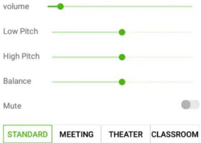
The Sound Mode page displays options including STANDARD, MEETING, THEATER and CLASSROOM.
- Drag the volume key bar directly or press the or button to change volume.
- Press Mute for silence mode
- Press RETURN to exit the menu.
Sound Mode
bar
| Category | MEETING | THEATER | CLASSROOM | | ------------ | ------- | ------- | --------- | | volume | 1 | 0 | 0 | | Low Pitch | 0 | 1 | 0 | | High Pitch | 0 | 1 | 0 | | Balance | 0 | 1 | 0 | | Mute | 0 | 0 | 1 |Screen Setting
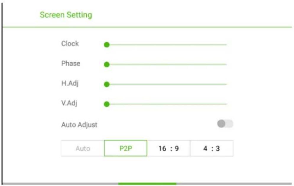
The Screen Setting page displays options including Auto, P2P, 16:9 and 4:3. Two ways are used to set the options:
- Click an icon and set the option.
- Press ◀ or ▶ and press OK to modify the option. Press RETURN to exit the menu.
• Under different input sources, the screen settings could be different.
• Under OPS, HDMI 1-HDMI 4 and DP signal source.
Screen Setting
natural_image
Solid green gradient background with no text, symbols, or discernible objectsAuto
P2P
16:9
4:3
• Under AV signal source, the P2P mode cannot use.
Screen Setting
natural_image
Solid green gradient background with no text, symbols, or discernible objectsAuto
P2P
16:9
4:3
• Under VGA signal source, Auto mode cannot use.
Display Setting
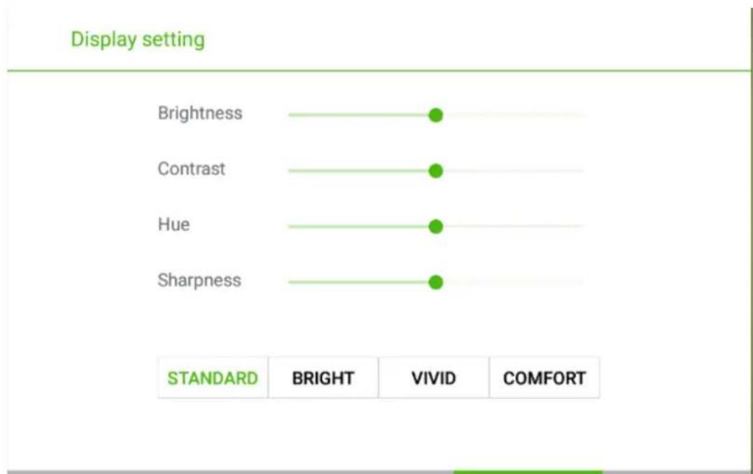
The Display setting page displays options including STANDARD, BRIGHT, VIVID and COMFORT.
Two ways are used to set the options:
- Click an icon and set the option.
- Press ◀or▶ and press OK to modify the option. Press RETURN to exit the menu.
bar
| Display setting | BRIGHT | VIVID | COMFORT | | --------------- | ------ | ----- | ------- | | Brightness | 10 | 10 | 10 | | Contrast | 10 | 10 | 10 | | Hue | 10 | 10 | 10 | | Sharpness | 10 | 10 | 10 |7 ECO Mode

WARNING
- Please switch off the screen when it is not used, and enable the function of Audio Only when you do not need to watch the display, helping to reduce power consumption and save energy.
- On the premise of ensuring viewing effect, the energy consumption can be reduced by lowering display brightness.
- To better save energy, the automatic power-off function is configured for the screen and the default duration is 10 minutes.
If no operation is performed in 10 minutes, the screen is switched automatically to sleep mode (the same as power off) for reducing energy consumption.
Press ECO on the remote controller to enter the backlight mode page. Press ECO to switch among ECO, Auto and Standard.
- In the ECO mode, the power output is reduced 50%.
- In the Auto mode, the screen automatically adjusts the screen brightness according to the light in the environment. When the light is strong, the screen brightens. When the light is weak, the screen darkens.
- In the Standard mode, the screen brightness keeps the same.
8 Serial Port Control
The RS-232 port of the interactive touch screen is defined as follows:
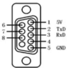
Connect RS-232 port to the PC or controlling device. Enable RS-232 serial port connection and complete the following configuration.
| Port Number: COM 1 (Set the value according to the port number of the PC or controlling device.) | |||
| Bit rate 19200 Odd/ | even check None | ||
| Data bit 8 Stop bit 1 | |||
The following table lists button controlling codes. The buttons share same functions with corresponding buttons on the remote controller.
| Function Controlling | Code Function Controlling Code | ||
| Power on | 7F 08 99 A2 B3 C402 FF 01 00 CF | 1 | 7F 08 99 A2 B3 C402 FF 01 21 CF |
| Power off | 7F 08 99 A2 B3 C402 FF 01 01 CF | 2 | 7F 08 99 A2 B3 C402 FF 01 22 CF |
| Mute | 7F 08 99 A2 B3 C402 FF 01 02 CF | 3 | 7F 08 99 A2 B3 C402 FF 01 23 CF |
| Sound mode | 7F 08 99 A2 B3 C402 FF 01 05 CF | 4 | 7F 08 99 A2 B3 C402 FF 01 24 CF |
| Signal source | 7F 08 99 A2 B3 C402 FF 01 06 CF | 5 | 7F 08 99 A2 B3 C402 FF 01 25 CF |
| One button start | 7F 08 99 A2 B3 C402 FF 01 07 CF | 6 | 7F 08 99 A2 B3 C402 FF 01 26 CF |
| Display status | 7F 08 99 A2 B3 C402 FF 01 09 CF | 7 | 7F 08 99 A2 B3 C402 FF 01 27 CF |
| HDMI 1 | 7F 08 99 A2 B3 C402 FF 01 0A CF | 8 | 7F 08 99 A2 B3 C402 FF 01 28 CF |
| HDMI 2 | 7F 08 99 A2 B3 C402 FF 01 0B CF | 9 | 7F 08 99 A2 B3 C402 FF 01 29 CF |
| HDMI 3 | 7F 08 99 A2 B3 C402 FF 01 0C CF | 0 | 7F 08 99 A2 B3 C402 FF 01 2A CF |
| Function Controlling Code Function Controlling Code | |||
| Intel PC(OPS) | 7F 08 99 A2 B3 C402 FF 01 38 CF | OK | 7F 08 99 A2 B3 C402 FF 01 2B CF |
| HDMI 4 | 7F 08 99 A2 B3 C402 FF 01 51 CF | 7F 08 99 A2 B3 C402 FF 01 2C CF | |
| DP | 7F 08 99 A2 B3 C402 FF 01 56 CF | 7F 08 99 A2 B3 C402 FF 01 2D CF | |
| VGA | 7F 08 99 A2 B3 C402 FF 01 0D CF | 7F 08 99 A2 B3 C402 FF 01 2E CF | |
| AV | 7F 08 99 A2 B3 C402 FF 01 11 CF | 7F 08 99 A2 B3 C402 FF 01 2F CF | |
| Up | 7F 08 99 A2 B3 C402 FF 01 13 CF | Menu | 7F 08 99 A2 B3 C402 FF 01 1B CF |
| Down | 7F 08 99 A2 B3 C402 FF 01 14 CF | Home page | 7F 08 99 A2 B3 C402 FF 01 1C CF |
| Listen alone | 7F 08 99 A2 B3 C402 FF 01 15 CF | Return(Exit) | 7F 08 99 A2 B3 C402 FF 01 1D CF |
| ECO | 7F 08 99 A2 B3 C402 FF 01 16 CF | Search | 7F 08 99 A2 B3 C402 FF 01 1E CF |
| VOL- | 7F 08 99 A2 B3 C402 FF 01 17 CF | Capture | 7F 08 99 A2 B3 C402 FF 01 1F CF |
| VOL + | 7F 08 99 A2 B3 C402 FF 01 18 CF | Auto ADJ | 7F 08 99 A2 B3 C402 FF 01 20 CF |
| Freeze 7F 08 99 A2 | B3 C402 FF 01 3B CF | Acoustic Mode | 7F 08 99 A2 B3 C402 FF 03 XX CFNote:XX indicate various mode:00-Standard, 01-Music,02-Film, 03-News, 04-User, 05-temporary 1, 06-temporary 2 |
| volume setting | 7F 08 99 A2 B3 C402 FF 05 XX CF | Energy saving mode | 7F 08 99 A2 B3 C402 FF 06 XX CFNote:XX indicate various mode:00-standard, 01-energy saving, 02-auto |
| Firmware version query | 7F 08 99 A2 B3 C402 FF 01 3D CF | Backlight brightness increase | 7F 08 99 A2 B3 C402 FF 01 47 CF |
| Backlight brightness decrease | 7F 08 99 A2 B3 C402 FF 01 48 CF | Backlight brightness setting | 7F 08 99 A2 B3 C402 FF 09 XX CF |
| Switch child lock | 7F 08 99 A2 B3 C402 FF 01 57 CF | Child lock mode | 7F 08 99 A2 B3 C402 FF 01 58 CF |
9 VGA Signal Input
VGA (Video Graphics Array) is the computer display standard for analog signal. VGA port is the special port on the computer which uses the VGA standard for data input. The following table lists the specifications of various VGA signal input.
Note:
The VGA signal input is available only when the screen is in PC mode.
| SN Standard | Resolution | Refresh Rate(Hz) | Horizontal Frequency (KHz) | Vertical Frequency (Hz) | Horizontal/Vertical Sync Polarity (TTL) | |
| 1 VGA 640x | 480 60 31.5 | 60 N/N | ||||
| 2 VGA 640x | 480 72 37.9 | 72 N/N | ||||
| 3 VGA 640x | 480 75 37.5 | 75 N/N | ||||
| 4 VGA 800x | 600 56 35.1 | 56 P/P | ||||
| 5 VGA 800x | 600 60 37.9 | 60 P/P | ||||
| 6 VGA 800x | 600 72 48.1 | 72 P/P | ||||
| 7 VGA 800x | 600 75 46.9 | 75 P/P | ||||
| 8 VGA 1024x | 768 60 48.4 | 60 N/N | ||||
| 9 VGA 1024x | 768 70 56.5 | 70 N/N | ||||
| 10 VGA 1024x | 768 75 60 | 75 N/N | ||||
| 11 VGA 1280x | 960 60 60 | 60 N/N | ||||
| 12 VGA 1280x | 960 75 75.159 | 75 N/N | ||||
| 13 VGA 1280x | 1024 60 | 64 60 P/P | ||||
| 14 VGA 1280x | 1024 75 | 80 75 P/P | ||||
| 15 VGA 1600x | 1200 60 | 75 60 P/P | ||||
| 16 VGA 1920x | 1080 60 | 66.547 59.988 | P/P |
10 Mutilmedia Fotmat Support
VGA (Video Graphics Array) is the computer display standard for analog signal. VGA port is the special port on the computer which uses the VGA standard for data input. The following table lists the specifications of various VGA signal input.
Note:
The VGA signal input is available only when the screen is in PC mode.
| Media Type | File Format File Extension | |
| Image JPEG, BMP, PNG .jpg, .bmp, .png | ||
| Movie | MPEG1, MPEG2, MPEG4, H.264, H.265, RM, RMVB, MOV, MJPEG, VC1, DivX, FLV (Support 1080P, 4K HD Decoding) | .avi, mpg, .dat, .vob, .div, .mov, .mkv ,rm, .rmvb, .mp4, .ts, .trp, .asf, .flv |
| Music MP3, | M4A, (AAC) .mp3, .m4a | |
| Text TXT ,txt |
11 Common Faults and Solutions
| Symptom Possible Cause Solution | ||
| The service program fails to be connected. | The drive program is not correctly installed. | Install the drive program correctly. |
| The USB port (lead) is not connected or is faulty. | Change the USB lead or check if the USB port is faulty. | |
| The infrared tube is blocked. | Ensure that the surrounding infrared tubes are not blocked. | |
| Repositioning is required every time the screen is switched on. | The computer is equipped with a recovery card. | Disable computer protection and perform the positioning again. |
| The positioning is inaccurate. | The positioning is not performed properly. | Press AUTO on the remote controller to show the full screen, and use the pen provided with the screen to perform positioning again. |
| The cursor of the pen is unstable when the pen is used. | The writing method is incorrect. | You are advised to use the pen rather than a finger to write. Hold the pen as far to the nib as possible. The angle between the pen and screen needs to be greater than 60 degrees. Do not touch the screen with your sleeve or wrist. |
| Strong light or infrared interference exists. | Remove the interference source or change the using environment. | |
| The handwriting is discontinuous.(Part of the handwriting cannot be displayed.) | The writing method is incorrect. | You are advised to use the pen rather than a finger to write. Hold the pen as far to the nib as possible. The angle between the pen and screen needs to be greater than 60 degrees. Do not touch the screen with your sleeve or wrist. |
| The covering area of the nib does not meet the requirement or the nib is too small. | Change the nib or use a pen with larger covering area. | |
| The infrared tube is blocked. | Check if infrared tubes are blocked. | |
| Strong light or infrared interference exists. | Remove the interference source or change the using environment. | |
| Symptom Possible | Cause Solution | |
| The handwriting cannot be shown or no touch signal is detected. | The color of the pen is the same as or similar to the background color. | Change the color of the pen. |
| Your hand or other objects are on the screen when you are writing. | You are advised to use the pen rather than a finger to write. Hold the pen as far to the nib as possible. The angle between the pen and screen needs to be greater than 60 degrees. Do not touch the screen with your sleeve or wrist. | |
| Strong light or infrared interference | Remove the interference source or change the using environment. | |
| The writing method is incorrect. | You are advised to use the pen rather than a finger to write. Hold the pen as far to the nib as possible. The angle between the pen and screen needs to be greater than 60 degrees. Do not touch the screen with your sleeve or wrist. | |
| Not sound is played and no image is displayed. | ·Check whether the power plug is inserted into the power socket and whether the screen is powered on. ·Check whether the rocker switch on the interactive touch screen is switched on. ·Check whether the Standby button on the remote controller is pressed. ·Check whether the video and audio input cables are connected correctly. ·Check whether the screen is switched to the right signal source. ·Check the settings on image brightness and contrast. ·Check the volume. | |
| Image is displayed properly, but no sound is played. | ·Check the volume. ·Check whether the Mute button on the remote controller is pressed. ·Check whether the audio cable between the PC and interactive touch screen is connected correctly. | |
| Symptom Possible Cause Solution | ||
| No image is displayed or the image is black and white. | Modify the color settings.Check the color system. | |
| The image or sound is interrupted. | Find out the electric appliance that causes the interference and move it away from the interactive touch screen.Do not share the power socket of the screen with the electric appliance that causes interference. | |
| The remote controller fails. | Change the batteries.Clean the signal emitter at the top of the remote controller. (Check whether it is blocked.)Check contacts of the batteries. | |
| The PC cannot be started. (This scenario is applicable only to screen models operating with the PC.) | Check whether the PC adapter is correctly connected and whether the PC is powered on.Check whether the PC is connected correctly to the interactive touch screen. | |
The following symptoms are not faults:
- A very few of constantly bright or dark pixels, such as tiny red, blue, green or dark points, may exist on the LED. This symptom is not a fault and does not affect running functions of the screen.
- Slight sound may occur due to the backlight adjustment or ventilation. This is a normal symptom.
- The image and sound are normal. However, you can sense static electricity when you touch the LED and metal back cover. This is a normal symptom.
12 Care and Maintenance
Maintenance Tips
- Do not put or install the product near a heat source or under direct sunlight, or in dusty or humid places, or somewhere the product may be hit or damaged by mechanical vibration. To maximize the performance, it needs to be put away from equipment such as grid, large metal objects and radar stations as far as possible.
- Do not wipe the screen with any chemical reagent. Solvents may damage the enclosure or paint. If the screen is stained by dust, cut off the power and then clean the screen using a dried cloth with a little of warm water. Use a clean soft cloth to clean the LED of the screen.
- Do not frequently switch on and off the product, which may shorten the product service life. After the screen is switched off, wait for three minutes before switching it on again If the product is not to be used for a long period of time, please power off the product and pull out the power plug.
- Do not maximize the brightness and contrast of the LED for a long period of time, which may shorten the LED service life.
- Do not use a hard object to write on the touch screen, which may scratch the LED.
Clean the Infrared Tube
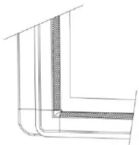
The interactive touch screen uses the horizontal and vertical infrared matrix to detect and locate the user's touch. The screen is surrounded by an infrared tube (including the infrared acceptor and emitter), which forms an infrared net covering on the screen surface. When a user touches the screen, fingers or other opaque objects block the infrared rays that cross the touch point, which helps the controller detect the coordinate position of the touch point.
Dust is easily retained on the screen surface due to its long-term exposure in the air and causes ineffective touch or inaccurate positioning. Therefore, you need to clean the infrared tube around the screen regularly.
natural_image
Pure technical line drawing of a corner joint or structural detail (no text or symbols)13 Technical Parameters
| Specification Parameter | |
| Backlight Type LED | |
| Aspect Ratio 16:9 | |
| Physical Resolution | 3840 x 2160 Pixel (4K_UHD Model) / 1920 x 1080 (2K_FHD Model) |
| Viewing Angle 178° | |
| Diaplay Colors 10bits | |
| LCD Brightness 370cd/m | |
| Response Time (Typical) 8ms | |
| Viewing Angle 178° | |
| Life Time (Working hours) 30,000 hours | |
| Power Consumption | 65, 70 inch: Maximum <220W75 inch: <350W80, 86 inch: <450WStandby Mode: ≤0.5W |
| Working Voltage AC 100V-240V, 50 Hz/60Hz | |
| Input Current | 65,70 inch: Max 2.5A75 inch: Max 4.0A80, 86 inch: Max 4.5A |
| Touch Surface Material Tempered glass | |
| Touch Surface Technology | Anti-Glare glass(New Generation Anti-Glare Glass optional) |
| Transparency | >88% |
| Sensing Method | Infrared Touch |
| Touch Point | 10 Points |
| Writing Method Finger or pen | |
| Cursor Speed | 100Point/s |
| Positioning Accuracy | 5mm |
| Communication Interface | USB-B |
| Front Interface Input Ports | Microphone(3.5mm) x 1, USB(Touch) x 1, USB(OPS) x 2, HDMI x 1, Display Port x 1, USB(Android) x 1 |
| Rear Side Ports | HDMI x 3, HDMI out x 1 USB(Touch) x 3, Microphone(3.5mm) x 1, VGA x 1, VGA Audio x 1, USB3.0 x 1, Mini SD Reader x 1 |
| Bottom Ports | AV in x 1, LAN in x 1, LAN out x 1, RS232 x 1, SPDIF, Earphone x 1 |
| Multimedia File Formats Support | Image: JPEG, BMP, PNGVideo: MPEG1, MPEG2, MPEG4, H.264, H.265,RM, RMVB, MOV, MJPEG, VC1, DivX, FLV(Support 1080P, 4K HD Decoding)Audio: MP3, M4A, (AAC) |
| Speaker Position Forward | |
| Speaker Rated Impedance 8Ω | |
| Speaker Freq. Response 90Hz (±20%) - 18kHz | |
| Speaker Max. Power Output 15 W*2 | |
| Transmission Range 5m | |
| Storage Temperature/Humidity -20°C - 60°C, 20% - 90% | |
| Working Temperature/Humidity 0°C - 40°C, 20% - 80% | |
| Installation Method Wall-mounted / Floor Stand | |
| I/O Ports Remark (for 4K_UHD Model) | The HDMI 1, Display port and rear side HDMI 4 can support 4K, 30Hz.The HDMI 2, HDMI 3, HDMI Out ports can support 4K, 60Hz.(Note: there is an exception that HDMI 1 & 4 ports can support 4K, 60Hz, when using YUV420 media player device) |
* We may modify the user manual without prior notice.
* If you discover any unclear presentation, mistake or omission in this manual, please contact us immediately. We are not liable for any loss or damage if you fail to contact us.

- Interactive Touch Screen User Manual
- Welcome:
- Contents
- Safety Instruction 1
- Toolbar Introduction 19
- Signal Source Selection 31
- Safety Instruction
- CAUTION
- Installation Requirement
- BEARING
- WARNING
- NOTE:
- Introduction
- Outer Appearance
- Control Panel
- Control Panel 1
- Control Panel 3
- Functions of the Remote Controller
- Instructions of Remote Controller
- Basic Operation
- Power on
- Power off
- Positioning Method for Window 7 System
- TIP
- OPS Installation
- Toolbar Introduction
- Task Manager
- View Running Programs
- Switch Programs
- End Programs
- Whiteboard
- New Whiteboard and Settings
- Pen, Line Weight and Color
- Eraser
- Cancel
- Screen Capture
- Print, Clear and Freeze Screen
- Gallery
- •Full preview
- File Manage
- System Settings
- Browser
- Audio Only
- Child Lock Setting
- Remote Boot
- Disable Android USB Port
- Application Programs
- Calculator
- Music
- Temperature Reminder and Thermal Shutdown
- Temperature Reminder
- Thermal Shutdown
- Signal Source Selection
- Source
- Menu
- Sound Mode
- Screen Setting
- Display Setting
- ECO Mode
- Serial Port Control
- VGA Signal Input
- Mutilmedia Fotmat Support
- Care and Maintenance
- Maintenance Tips
- Clean the Infrared Tube
Brand : Newline
Model : TruTouch TT-7516UB
Category : Screen