
XV Crosstrek Hybrid (2015) - Automobile SUBARU - Free user manual and instructions
Find the device manual for free XV Crosstrek Hybrid (2015) SUBARU in PDF.


| Product Type | Automobile |
| Brand | Subaru |
| Model | XV Crosstrek Hybrid (2015) |
| Category | Automotive |
| Fuel Type | Unleaded gasoline (87 AKI or higher) |
| Fuel Tank Capacity | 13.7 US gal (52 L, 11.4 Imp gal) |
| Engine Oil Capacity | 5.1 US qt (4.8 L, 4.2 Imp qt) with filter |
| Hybrid Battery Type | Nickel-metal hydride high voltage battery |
| Electric Motor | Drive electric motor (located in transmission) |
| Safety Systems | SRS airbags (frontal, side, curtain), seatbelt pretensioners, ABS, Vehicle Dynamics Control, Hill Start Assist, Tire Pressure Monitoring System |
| Drive System | Symmetrical All-Wheel Drive (AWD) |
| Transmission | Lineartronic CVT (Continuously Variable Transmission) |
| Steering | Power-assisted rack-and-pinion |
| Brakes | Disc brakes with Electronic Brake Force Distribution (EBD) |
| Climate Control | Automatic and manual climate control options |
| Audio System | AM/FM/CD/MP3 audio system with multifunction display |
| Power Outlets | 12V power socket (front) |
| Seating Capacity | 5 passengers |
| Manual Pages | 564 |
| Manual Language | English |
| Manual Format | PDF download |
| Warranty | Subaru Limited Warranty, Emission Control Systems Warranty (US/Canada) |
| Hybrid Features | EV driving mode, regenerative braking, automatic engine stop/start, pedestrian alert system |
Frequently Asked Questions - XV Crosstrek Hybrid (2015) SUBARU
User questions about XV Crosstrek Hybrid (2015) SUBARU
0 question about this device. Answer the ones you know or ask your own.
Ask a new question about this device
Download the instructions for your Automobile in PDF format for free! Find your manual XV Crosstrek Hybrid (2015) - SUBARU and take your electronic device back in hand. On this page are published all the documents necessary for the use of your device. XV Crosstrek Hybrid (2015) by SUBARU.
USER MANUAL XV Crosstrek Hybrid (2015) SUBARU
CongratulationschoosingaSUBARUvehicle. This Owner's Manual has all the information necessary to keep your SUBARU in excellent condition and to properly maintain the emission control system for minimizing emission pollutants. We urge out to read this manual carefully so that you understand your vehicle and its operation. For information not found in this Owner's Manual, such as details concerning repairs or adjustments, please contact the SUBARU dealer from whom you purchase your SUBARU or thenearest SUBARU dealer.
Theinformation, specifications and illustrations found in this manual are those ineffect at the time of printing. FUJIHEAVY INDUSTRIESLTD. reserv est heright to changes specifications and designs at any timewithout priornotice and without incurring any obligation tomakethesameorsimilar changes on vehicles previously sold. This Owner's Manual appliesto all models and covers allequipment, including factory installed options. Some explanations, therefore may before equipment not installed in your vehicle.
Pleaseleavethismanualinthevehicleatthetimeofresale.The nextownerwillneedtheinformationfoundherein.
natural_image
Line drawings of two cars, one front and one side, shown from top and side views (no text or symbols)Warranties
■WarrantiesforU.S.A.
SUBARUvehiclesdistributedbySubaru ofAmerica,Inc.andsoldatretailbyan authorizedSUBARUdealerintheUnited Statescomewiththefollowingwarranties:
•SUBARULimitedWarranties
●FederalEmissionControlSystems
Warranties
●CaliforniaEmissionsControlSystems Warranties
Allwarrantyinformation,includingapplicability,detaisofcoverageandexclusions,isinthe"WarrantyandMaintenance Booklet".Pleasereadthesewarranties carefully.
WarrantiesforCanada
SUBARUvehiclesdistributedbySubaru Canada, Inc. and sold at retail by an authorized SUBARU dealer in Canada comewith the following warranties:
- SUBARULimitedWarranty
●EmissionControlSystemWarranty
Allwarrantyinformation,includingapplicability,detailsofcoverageandexclusions,isinthe"WarrantyandServiceBooklet".Pleasereadthesewarrantiescarefully.
■ModelswithHIDheadlights
CAUTION
HighIntensityDischarge(HID)headlightscontainmercury. For that reason, it is necessary to remove HID headlights before vehicled disposal. Onceremoved, pleasereuse, recycle or dispose of the HID headlights a hazardous waste.
■ ModelswithoutHIDheadlights
NOTE
This vehicle does not contain mercury devices or parts.
HowtousethisOwner's Manual
■UsingyourOwner'sManual
Before you operate your vehicle, carefully read this manual. Top protect yourself and extend the service life of your vehicle, follow the instructions in this manual. Failure to observ these instructions may result in serious injury and damage to your vehicle.
Thismanualiscomposedoffourteen chapters.Eachchapterbeginswithabrief tableof contents,soyou canusuallytellat aglanceifthatchaptercontainsthe informationyouwant.
Chapter1: Seat, seatbelt and SRS airbags
Thischapterinformsyouhowtousethe seatandseatbeltandcontainsprecautionsfortheSRSairbags.
Chapter2:Keysanddoors
Thischapterinformsyouhowtooperate thekeys, locksandwindows.
Chapter3: Instrumentsandcontrols
Thischapterinformsyouabouttheoperation ofinstrument panelindicators and howtouse theinstrumentsandother switches.
-CONTINUED-
Chapter4:Climatecontrol
Thischapterinformsyouhowtooperate theclimatecontrol.
Chapter5:Audio
Thischapterinformsyouhowtooperate youraudiosystem.
Chapter6: Interiorequipment
Thischapterinformsyouhowtooperate interiorequipment.
Chapter7: Starting and operating
Thischapterinformsyouhowtostartand operateyourSUBARU.
Chapter8:Drivingtips
This chapter informs you how to drive your SUBARU in various conditions and explain somes safety tips on driving.
Chapter9: Incaseofemergency
Thischapterinformsyouwhattodoifyou haveaproblem,suchasaflattireor engineoverheating.
Chapter10: Appearancecare
Thischapterinformsyouhowtokeepyour SUBARUlookinggood.
Chapter11: Maintenance and service
Thischapterinformsyouwhenyouneed totakeyourSUBARUtothedealerfor scheduledmaintenanceandinformsyou howtokeepyourSUBARUrunning properly.
Chapter12:Specifications
ThischapterinformsyouaboutdimensionsandcapacitiesofyourSUBARU.
Chapter13: Consumerinformation and Reportingsafetydefects
This chapter informs you about Uniform tirequality grading standards and reporting safety defects.
Chapter14:Index
Thisisanalphabeticallistingofallthat'sin thismanual.Youcanuseittoquicklyfind somethingyouwanttoread.
■ Safetywarnings
YouwillfindanumberofWARNINGS, CAUTIONsandNOTEsinthismanual. Thesesafetywarningsalertyoutopotentialhazardsthatcouldresultininjuryto youorothers.
Pleasereadthesesafetywarningsaswell asallotherportionsofthismanualcarefullyinordertogainabetterunderstandingofhowtouseyourSUBARUvehicle safely.

WARNING
AWARNINGindicatesasituationin whichseriousinjuryordeathcould resultifthewarningisignored.

CAUTION
ACAUTION indicates asituation in which injury or damage to your vehicle, or both, could result if the caution is ignored.
NOTE
ANOTEgivesinformationorsuggestionshowtomakebetteruseofyour vehicle.

Safetysymbol

natural_image
Gray circular prohibition symbol with diagonal line (no text or numbers)000013
Youwillfindacirclewithaslashthroughit inthismanual. Thissymbolmeans “Do not”, “Do not do this”, or “Do not let this happen”, depending upon the context.
Abbreviationlist
Youmayfindseveralabbreviationsinthis manual. Themeaningsoftheabbreviationsareshowninthefollowinglist.
| Abbreviation | Meaning |
| A/CAirconditioner | |
| ABSAnti-lockbrakesystem | |
| AKIAntiknockindex | |
| ALRAutomaticlockingretractor | |
| AWDAII-wheeldrive | |
| CVT | Continuouslyvariabletrans-mission |
| DRLDaytimerunninglight | |
| EBD | Electronicbrakeforceddistri-bution |
| ELREmergencylockingretractor | |
| EVElectricvehicle | |
| GAWGrossaxleweight | |
| GAWR | Grossaxleweighitrating |
| GPS | Globalpositioningsystem |
| GVW | Grossvehicleweight |
| GVWR | Grossvehicleweighitrating |
| HEV | Hybridelectricvehicle |
| HID | Highintensitydischarge |
| INTIntermittent | |
| Abbreviation | Meaning |
| LATCH | Lower anchors and tethers for children |
| LEDLightemittingdiode | |
| LSDLimitedslip | differential |
| MILMalfunction | indicatorlight |
| MMT | Methylcyclopentadienyl man-ganesetricarbonyl |
| OBD | On-boarddiagnostics |
| RON | Researchoctanenumber |
| SRS | Supplemental restraintsys-tem |
| TINTire identific-tionnumber | |
| TPMS | Tirepressuremonitoringsys-tem |
Vehicle symbols
Therearesomeofthesymbolsyoumay seeonyourvehicle.
For warning and indicator lights, refer to "Warningandindicatorlights" 29.
| Mark | Name |
| WARNING | |
| CAUTION | |
| Readtheseinstructionscarefully | |
| Wear eyeprotection | |
| Batteryfluidcontainssulfuric acid | |
| Keepchildrenaway | |
| Keepflamesaway | |
| Preventexplosions |
Safetyprecautionswhen driving
■ SeatbeltandSRSairbag

WARNING
- Allpersonsinthevehicleshould fastentheirseatbeltsBEFORE thevehiclestartstomove. Otherwise, thepossibilityofserious injurybecomesgreaterinthe eventofasuddenstoporaccident.
- Toobtainmaximumprotectionin theeventofanaccident, the driverandallpassengersinthe vehicleshouldalwayswearseatbeltswhenthevehicleismoving. TheSRS(SupplementalRestraint System)airbagdoesnotdoaway withtheneedtofastenseatbelts. Incombinationwiththeseatbelts, itoffersthebestcombined protectionincaseofaserious accident.
Notwearingaseatbeltincreases thechanceofsevereinjuryor deathinacrashevenwhenthe vehiclehastheSRSairbag.
•The SRSairbags deploy with considerable speed and force. Occupants who are out of proper position when the SRSairbag deploys could suffer very serious injuries. Because the SRSairbag needs enough space for deployment, the drivers should always sit upright and well back in these seat as far from the steering wheel as practical while still maintaining full vehicle control and the front passenger should move these seat as far back as possible and sit upright and well back in these seat.
For instructions and precautions, carefully read the following sections.
- Fortheseatbeltsystem,referto"Seatbelts" © 1-11.
- FortheSRSairbagsystem, referto "*SRSairbag(SupplementalRestraint Systemairbag)" 1-37.
Childsafety

WARNING
●Neverholdachildonyourlapor inyourarmswhilethevehicleis moving. Thepassengercannot protectthechildfrominjuryina collision, because thechild will becaught between thepassengerandobjectsinsidethevehicle.
- Whileridinginthevehicle, infants and small children should always be placed in the REAR seat in an infant or child restraint system which is appropriate for the child's age, height and weight. If a child is too big for a child restraint system, the child should sit in the REAR seat and be restrained using these seat belts. According to accident statistics, children are safer when properly restrained in there are seating position than in the front seat- ing positions. Never allow a child to stand up porkneel on these seat.
- PutchildrenintheREARseat properlyrestrainedatalltimesin achildrestraintdeviceorina seatbelt.TheSRSairbagdeploys
with considerable speed and force and can injure even kill children, especially if they are 12 years of age and under and are not restrained or improperly restrained. Because children are lighter and weaker than adults, the risk of being injured from deployment is greater.
●NEVERINSTALLAREARWARD FACINGCHILDSEATINTHE FRONTSEAT.DOINGSORISKS SERIOUSINJURYORDEATHTO THECHILDBYPLACINGTHE CHILD'SHEADTOOCLOSETO THESRSAIRBAG.
- Alwaysturnthechildsafetylocks to the "LOCK" position when childrensitintherearseat. Seriousinjurycouldresultifa childaccidentallyopensthedoor andfallsout. Referto "Child safetylocks" 2-32.
●Alwayslockthepassenger'swindowsusingthelockswitchwhenchildrenareridinginthevehicle.Failuretofollowthisprocedurecouldresultininjurytoachildoperatingthepowerwindow.Referto"Windows" 2-32.
●Neverleaveunattendedchildren,
adultsoranimalsinthevehicle. They could accidentally injure themselves or other through inadvertent operation of the vehicle. Also, on hotorsunny days, temperature in a closed vehicle could quickly become high enough to cause severe or possibly fatal injuries to them.
- Whenleavingthevehicle,close allwindowsandlockalldoors.
For instructions and precautions, carefully read the following sections.
- Fortheseatbeltsystem, referto "Seatbelts" 1-11.
- Forthechildrestraintsystem,referto "Childrestraintsystems" 1-24.
- FortheSRSairbagsystem, refer to "SRSairbag(SupplementalRestraint Systemairbag)" 1-37.
■Engineexhaustgas(carbon monoxide)

WARNING
●Neverinhaleengineexhaustgas. Engineexhaust gascontains carbonmonoxide,acolorless andodorlessgaswhichisdangerous,orevenlethal,ifinhaled.
●Alwaysproperlymaintaintheengineexhaustsystemtoprevent engineexhaustgasfromenteringthevehicle.
●Neverrunthehybridsystemina closedspace, such as agarage, except for the brief time needed to drivethe vehicle in or out of it.
- Avoidremaininginaparked vehicleforalengthytimewhile thehybridsystemisrunning.If thatisunavoidable,thenusethe ventilationfantoforcefreshair intothevehicle.
●Alwayskeepthefrontventilator inletgrillefreefromsnow,leaves orotherobstructionstoensure thattheventilationsystemalwaysworksproperly.
- Ifatanytimeyoususpectthat exhaustfumesareenteringthe vehicle, have the problem checkedandcorrectedassoon as possible. If you must drive undertheseconditions,drive onlywithallwindowsfullyopen.
- Keepthereargateclosedwhile drivingtopreventexhaustgas fromenteringthevehicle.
■ Drinkinganddriving

WARNING
Drinkingandthendrivingisvery dangerous.Alcoholinthebloodstreamdelaysyourreactiontime andimpairsyourperception,judgmentandattentiveness.Ifyoudrive afterdrinking-evenifyoudrinkjust alittle-itwillincreasetheriskof beinginvolvedinaseriousorfatal accident,injuringorkillingyourself, yourpassengersandothers.In addition,ifyouareinjuredinthe accident,alcoholmayincreasethe severityofthatinjury.
Pleasedon'tdrinkanddrive.
Drunkendrivingisoneofthemost frequentcausesofaccidents.Sincealcoholaffectsallpeopledifferently,youmay haveconsumedtoomuchalcoholtodrive safelyevenifthelevelofalcoholinyour bloodisbelowthelegallimit. Thesafest thingyoucandoisneverdrinkanddrive. Howeverifyouhavenochoicebutto drive,stopdrinkingandsoberupcompletelybeforegettingbehindthewheel.
Drugsanddriving

WARNING
Therearesomedrugs(overthe counterandprescription)thatcan delayyourreactiontimeandimpair yourperception.judgmentandattentiveness.Ifyoudriveaftertaking them,itmayincreaseyour,your passengers'andotherpersons'risk ofbeinginvolvedinaseriousor fatalaccident.
If you are taking any drugs, check with your doctor or pharmacist read the literature that accompanies the medication to determine if the drug you are taking can impair your driving ability. Don't drive after taking any medication that can make you drowsyor otherwise affect your ability to safely operate a motor vehicle. If you have a medical condition that requires you to take drugs, please consult with your doctor.
Neverdrive if you are under the influence of any illicit mind-altering drugs. For your own health and well-being, we urge you not to take illegal drugs in the first place and to seek treatment if you are addicted to those drugs.
■ Drivingwhentiredorsleepy

WARNING
Whenyouaretiredorsleepy,your reactiontimewillbedelayedand yourperception,judgmentandattentivenesswillbeimpaired.Ifyou drivewhentiredorsleepy,your, yourpassengers'andotherpersons'chancesofbeinginvolvedin aseriousaccidentmayincrease.
Pleasedonotcontinuetodrivebut insteadfindasafeplacetorestifyou aretiredorsleepy.Onlongtrips,you shouldmakeperiodicreststopstorefresh yourselfbeforecontinuingon your journey. When possible, you should share the drivingwithothers.
■ Modificationofyourvehicle

CAUTION
Your vehicles should not be modified other than with genuine SUBARU parts and accessories. Other types of modifications could affect its performance, safety, durability, and may even violate governmental regulations. In addition, damageor
performanceproblemsresulting frommodificationmaynotbecoveredunderwarranties.
■ Carphone/cellphone and driving

CAUTION
Donotuseacarphone/cellphone whiledriving;itmaydistractyour attentionfromdrivingandcanlead toanaccident.Ifyouuseacar phone/cellphone,pullofftheroad andparkinasafeplacebefore usingyourphone.InsomeStates/ Provinces,onlyhands-freephones maylegallybeusedwhiledriving.
■ Drivingvehiclesequipped withnavigationsystem

WARNING
Donotallowthemonitortodistract yourattentionfromdriving.Also,do notoperatethecontrolsofthe navigationsystemwhiledriving. Thelossofattentiontodriving couldleadtoanaccident.Ifyou
wishtooperatethecontrolsofthe navigationsystem,firsttakethe vehicleofftheroadandstopitina safeplace.
■Drivingwithpets
Unrestrainedpetscaninterferewithyour drivinganddistractyourattentionfrom driving.Inacollisionorsuddenstop, unrestrainedpetsorcagescanbethrown aroundinsidethevehicleandhurtyouor yourpassengers.Besides,thepetscan behurtunderthesesituations.Itisalsofor theirownsafetythatpetsshouldbe properlyrestrainedinyourvehicle.Restrainapetwithaspecialtraveling harnesswhichcanbesecuredtotherear seatwithaseatbeltoruseapetcarrier whichcanbesecuredtotherearseatby routingaseatbeltthroughthecarrier's handle.Neverrestrainpetsorpetcarriers inthefrontpassenger'sseat.Forfurther information,consultyourveterinarian, localanimalprotectionsocietyorpet shop.
Tirepressures
Checkand, if necessary, adjust the pressure of each treat least once a month and before any long journey.
Check the tire pressure when the tires are cold. Use a pressure gaugetoadjust the tire pressure to the value shown on the tire placard. Ford detailed information, refer to "Tires and wheels" 11-22.

WARNING
Drivingathighspeedswithexcessivelylowtirepressurescancause thetirestodeformseverelyandto rapidlybecomehot.Asharpin-creaseintemperaturecouldcause treadseparation,anddestructionof thetires. Theresultingloss of vehiclecontrolcouldleadtoan accident.
Generalinformation
■ Californiaproposition65 warning

WARNING
Engineexhaust, some of its constituents, and certain vehicle components contain a remit chemicals known to the State of Californiato cause cancer and birth defect or other reproductive harm. In addition, certain fluids in vehicles and certain components of product wear contain a remit chemical known to the State of Californiatocause cancer and birth defects or other reproductive harm.
■ CaliforniaPerchlorateAdvisory
Certainvehiclecomponentssuchasairbagmodules,seatbeltpretensionersand keylessentrytransmitterbatteriesmay contain perchloratematerial. Special handling may apply for service or vehicle endoflifedisposal. Seewww.dtsc.ca.gov/hazardouswaste/perchlorate.
■ Noisefromunderthevehicle NOTE
Youmayhearanoisefromunderthe vehicleapproximately5to10hours aftertheignitionswitchisturnedtothe "LOCK"(off)position.However,this doesnotindicateamalfunction.This noiseiscausedbytheoperationofthe fuelevaporationleakagecheckingsystemandisnormal.Thenoisewillstop afterapproximately15minutes.
■ Eventdatarecorder
Thisvehicleisequippedwithanevent datarecorder(EDR).Themainpurposeof anEDRistorecord,incertaincrashor nearcrash-likesituations,suchasanair bagdeploymentorhittingaroadobstacle, datathatwillassistinunderstandinghow avehicle'ssystemsperformed.TheEDR isdesignedtorecorddatarelatedto vehicledynamicsandsafetysystemsfor ashortperiodoftime,typically30seconds orless.TheEDRinthisvehicleis designedtorecordsuchdataas:
- Howvarious systems in your vehicle were operating;
- Whetherornotthedriverandpassengersafetybeltswerebuckled/fastened;
- Howfar(ifatall)thedriverwas depressingtheacceleratorand/orbrake
pedal;and,
• Howfastthevehiclewastraveling.
Thesedatacanhelpprovideabetter understandingofthecircumstancesin whichcrashesandinjuriesoccur.NOTE: EDRdataarerecordedbyyourvehicle onlyifanon-trivialcrashsituationoccurs; nodataarerecordedbytheEDRunder normaldrivingconditionsandnopersonal data(e.g.,name,gender,age,andcrash location)arerecorded.However,other parties,suchaslawenforcement,could combinetheEDRdatawiththetypeof personallyidentifyingdataroutinelyacquiredduringacrashinvestigation.
ToreaddatarecordedbyanEDR, special equipmentisrequired, andaccesstothe vehicleortheEDRisneeded. In addition tothevehiclemanufacturer, otherparties, suchaslawenforcement, thathavethe specialequipment, canreadtheinformationiftheyhaveaccesstothevehicleor theEDR.
Hybridsystemfeatures

WARNING
Someofthecomponentsofthe hybridsystem(e.g.,highvoltage battery,electricmotor,etc.)arehigh voltageparts.Toavoidseriousinjuryordeath,carefullyreadthe followingdescriptions.
Yourvehicleisequippedwithahybrid system. Themainpowersourceforthis hybridsystemistheenginethough dependingonthecircumstances, the electricmotormayassistthepowerof theengine.Bycontrollingtheinteraction oftheengineandtheelectricmotor,ahigh levelofperformance,improvedfueleconomy,andareductioninexhaustemissions areachieved.
■ Generalinformationforstopping/restartingoftheengine andelectricmotor
NOTE
Fordetailsabouttheprocedurefor startingthehybridsystem,referto "Startingandstoppingthehybridsystem"7-8.
Theenginewillbeautomaticallystopped orrestarteddependingontheconditions ofthevehicle.
Whenstarting:
Theengineisusedtostartthevehicle moving. However, when the accelerator pedal is depressed lightly, the engine may remain stopped and the electric motor maybe usedtostartthevehicle moving.
Whenacceleratinggraduallyordriving ataconstantspeed:
- Whenthevehiclespeedislessthan25 mph(40km/h),itispossibletodriveusing onlythepoweroftheelectricmotor. However, whendriving inreverse, the enginewillrestartataspeedslowerthan thatexperienced whenthevehicle is movingforward.
- Whenthevehiclespeedis25mph(40 km/h)ormore, the electric motor power assiststheenginepower. However, when driving uphill, if it is more efficient to drive using engine power alone, the electric motormay not operate.
Whenacceleratingsharply:
Thepoweroftheelectricmotorisadded to thatoftheengine.
Whendrivingusingelectricmotor poweraloneandthenaccelerating:
The engine is restarted and the power of the electric motor is added to that of the engine.
Whenbraking:
The engine is stopped. The electric motor is used as a generator by using the rotation of the wheels and this charges the high voltage battery.
Whenthevehiclehasbeenstopped:
Theengineisstoppedtemporarily. Depending upon conditions, this may also occur before a complete stop has been achieved.
Depending on the position of the transmission select lever and the mode of the climate control, the engine and the electric motor are controlled as follows.
| Operation | Drivingonlyusingtheelectricmotorpower | Drivingwiththelectric motorassistingtheengine | Engineautomaticallystops | |
| Select lever is in the “D” position | Operational | Operational | Operational | |
| Selectleverisinthe“R” position | Selectleverhasbeenshifted intothe“R”positionwhilethe engineisautomatically stopped | OperationalOperational | Operational | |
| InothercasesNon-operationalOperationalNon-operational | ||||
| Manualmodeisselected *1 | Non-operationalOperationalOperational | |||
| The“modeor”modeoftheclimatesystemis selected *2 | Non-operationalOperational | Non-operational | ||
^1 : For details, refer to "Selection of manual mode" 7-17.
^2 : For details, refer to "Airflow mode selection" 4-6.
Operationoftheautomaticenginestop featurewilldependuponacombinationof thesevariousconditions. Forexample, whenyouselectthe"modeofthe climatecontrol, eveniftheselectleveris inthe"D"position,theenginewillnotstop automatically.
Theenginemaybeautomaticallystopped bythesystemwhenallofthefollowing conditionsaremet.
●theengineissufficientlywarmedup
●thehighvoltagebatteryand12V engineererastrbatteryareingoodcondition(plentyofelectricpowerremainsand thetemperatureiswithinthespecified temperaturerange)
●the" "modeor" mode of the climate control system is not selected
●theclimatecontrolfunctionisnotused or used with a negligible temperature differencebetweenthesettingtemperatureandthetemperatureinsidethe vehicle.
●theoutsidetemperatureishigherthan approximately 14°F (-10°C)
●theCHECKENGINEwarninglight/malfunctionindicatorlightisoff
●thevehicleisnot stopped onaroad thathasasteepslope
●negativepressureinthebrakebooster issufficient
●thebrakepedalisfirmlydepressed afterithasbeendepressedtodecelerate orstopthevehicle(Thesystemmaynot operateinsomecasesifthebrakepedal isnotfullydepressedorifthebrakeis appliedsuddenly.)
●theCVTfluidissufficientlywarmedup
- thetemperatureoftheCVTfluidisnot abnormallyhigh

EV(ElectricVehicle)modelamp
Iftheengineistemporarilystoppedby the system,theEV(ElectricVehicle)mode lamponthecombinationmeterwillilluminate.Thisindicatorlightwillturnoffwhen thesystemrestartstheengine.
NOTE
- The12Venginererastbartatteryisa specialhigh-performance battery. Whenreplacingthebattery,besureto replaceitwithagenuineSUBARU battery(orequivalent)designedspecificallyforuseinavehicleequipped withahybridsystem.Fordetails, consultyourSUBARUdealer.
- In the following cases, it may take sometimeforstopping/restartingthe enginefeaturetooperate.
-whenthe12V auxiliarybattery and/or12Venginererestartbatteryis dischargedbecausethevehiclehas notbeenusedforalongperiodof timeorforotherreasons.
-whentheoutsidetemperatureis veryhigh,orwhenitisverylow
-whentheterminalsofthe12V auxiliarybatteryand/or12Vengine restartbatteryaredisconnected afterreplacingthebattery
Also, in the following cases, the length of timethatthe engine is temporarily stopped by the system may be shorter.
- whentheoutsidetemperatureishigh, orwhenitislow(becausetheairconditioneror heatercannolongermaintain the settemperature)
- whenconsumptionofelectricityby electricalcomponentsishigh
-CONTINUED-

WARNING
Whendrivingontheelectricmotor alone, thereisnosoundcoming fromtheengine. Therefore, thereis apossibilitythatthesurrounding peopledonotnoticethevehicle startingandapproaching.Payattentiontoyoursurroundingswhile driving.

CAUTION
Dependingonthestateofthevehicle(forexample,ifthereislittle powerremainingonthehighvoltage battery),theenginemayautomaticallyrestart.Besuretodepressthe brakepedalwhilethevehicleis stationary.

Components

1) Engine
2)Driveelectricmotorassembly
3) Highvoltagebattery

1)12Venginerestartbattery
2) Electricmotor(locatedinthetransmission)
3) Highvoltagebattery
4)DC/DCconverter
5)12Vauxiliarybattery
6)Highvoltagecable(orange)
7)Servicedisconnectplug
-CONTINUED-
■Safetyprecautions
▼Precautionsfordailyuse

WARNING
The hybridsystemusesahigh voltage(100Vormore).Always observethefollowingprecautions. Otherwise,burnsorelectricshock couldoccur,resultinginserious injuryordeath.
- Wheninspectionorrepairis needed, always haveitperformedbyyourSUBARUdealer.
- Nevertouch, removeordisassemble the high voltage parts, high voltageable (orange) or their connectors.
- Nevertouchtheservicedisconnectplug. Theservicedisconnectplugisusedtocutoffthe voltageofthehighvoltagebatterywhenthevehicleisinspectedorserviced by a SUBARUdealer.

natural_image
Technical line drawing of a car interior showing a seatbelt and dashboard (no text or symbols)Highvoltagebatteryairintake

CAUTION
- Donotcoverthehighvoltage batteryairintake(locatedonthe leftnexttotherearseat)with luggageorclothes.Itisimportantthatnoliquidsoranyother substances or objects be allowed toentertheairintake.Please advisepassengersinthisareato usecarearoundtheairintaketo prevent anydebris from entering. Doingsomayresultinoverheatingormalfunctioningofthehigh voltagebattery.
•Inordertoensurewaterproofing, besuretoinstallthecargoarea
flooring. Ensure that large amountsofwaterdonotenter thecargoarea.Doingsomay resultinmalfunctionofthehybrid system including the high voltagebattery.
NOTE
Because the gasoline engine is the main powers source of this vehicle, it cannot run without gasoline.
▼Whenanaccidentoccurs

WARNING
Observethefollowingprecautions. Otherwise, serious injury (e.g., burns or electric shock) or death may be caused.
- Nevertouchthefollowingparts.
-Highvoltageparts
-Highvoltagecable(orange)
–Electricwiresexposedinside oroutsidethevehicle
- If there is liquid leaking from or coating anything, donottouchit under any circumstances. The high voltage battery electrolyte is a strong alkali. If the electrolyte
getsinyoureyesoronyourskin, itcouldleadtoseriousinjury.In theeventthatitdoesgetonyou, immediatelywashitoffwitha largeamountofwaterandseea doctorimmediatelyforexamination.
- lfafireoccursinthevehicle,put itoutwithaelectricalfireextinguisher.lfaelectricalfireextinguisherisnotavailable,usea largeamountofwaterfromafire hydrantorsimilarsource.
▼Whendisposingofyourvehicle

WARNING
Thenickel-metalhydridebatteryis used as a high voltage battery. For safety, observ the following precautions.
- If you are disposing of your vehicle, have a SUBARU dealer remove and collect the high voltage battery. If it is not properly collected, in addition to contributing to environmental pollution, it is possible that the following may occur, resulting in serious injury or death.
-Anaccidentinvolvingelectric shock that occurs when someonetouchesthehigh voltageportionsofanillegally dumpedorotherwiseimproperlydisposedhighvoltage battery.
-Anaccidentinvolvingelectric shock, heat generation, smokeemission, fire, explosion, leaking of the battery fluid, etc., caused by utilizing the high voltage battery in another vehicle.
- Donotofferthehighvoltage batteryforresale,transfer,modification,etc.underancircumstances. Particularlyinthecases ofresaleandtransfer,theother partyoftheresale/transfermay notrecognizethedangersofthe highvoltagebatterywhichcould resultinseriousinjury.
■Generalinformation
▼Tipsforhighvoltagebattery
●Theengineandtheregenerativebrake chargethehighvoltagebattery.Youdo nothavetochargethehighvoltage batteryfromanoutsidesource.However,
if the select lever is in the "P" or "N" position, the battery will not be charged. Even when driving in heavy traffic, place these elect lever in the "D" position.
•Inordertomaintainthebatteryingood condition, drivethevehicleatleastonce everyamonthforatleast30minutes. If youleavethevehicleforalongtime, the batterymaydischargeorthelifeofthe batterymaybeshortened.
▼Regardingsoundsandvibrations particulartothehybridsystem
The following sounds or vibration may occur when the hybridsystem is operating. However, these are characteristic to the hybridsystem and do not indicate a malfunction.
●Electricmotorsoundsheardfromthe enginecompartment(nearthetransmission)
● Soundsfromtheenginecompartment andfromthecargoareawhenstartingor stoppingthehybridsystem
- Operatingsoundofthehighvoltage batteryairintake(locatedontheleftside oftherearseats)orthecoolingfan (locatedinthecargoarea)
●Highfrequencysoundsfromaround thecargoarea
●Operationsoundsfromtheengine compartmentwhendrivingusingonly
-CONTINUED-
electricmotorpower
●Soundsorvibrationsfromtheengine compartmentduetoariseinengine accelerationwhilechargingthehighvoltagebattery
- Relayoperationsoundsfromtheenginecompartmentandrearofthevehicle
●Operationsoundsandelectricmotor soundswhendepressingthebrakepedal
●Vibrationswhenchangingfromelectric motordrivingtoengineDrivingorelse when the engine is restarted while stopped
▼PedestrianAlertsystem
Whendrivingonlyusingelectricmotor power(forwardandreversetraveling), a soundwillbemadetoalertpeopleinthe vicinitythatthevehicleisincloseproximity. ThisAlertsystemwilloperatewhen thevehiclespeedisapproximately15 mph(24km/h)orless.
ThepedestrianAlertsoundmaybedifficult forpeopleinthesurroundingareatohear inthefollowingcases.
●Thevehicleisinanoisyarea.
●Thevehicleisintherainorstrong wind.
It may be more difficult to hear the sound from therearofthe vehicle than from the front.
▼Regardingelectromagneticwaves
Highvoltagepartsandcables(orange) incorporateelectromagneticshielding. Theyemitalmostthesameamountof electromagneticwavesasconventional vehiclesorhomeelectronicappliances. However, somenoisemaybeemitted whenusingradioparts. Wheninstalling radioparts, consultyourSUBARUdealer.
▼Screendisplay
Youcandisplaythefollowinginformation onthemultifunctiondisplay.
●Statusofthehighvoltagebattery
- Energyflowbetweentheengine,electricmotor,highvoltagebatteryandwheels
Powerfromtheenginewillbedisplayedin orange,powerfromtheelectricmotorwill bedisplayedingreenandtheenergyflow chargingthehighvoltagebatterywillbe displayedinaqua.
| Display | Status |
| Whendrivingonly bytheengine power |
| Display | Status |
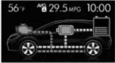 ZOM0382 ZOM0382 | Whenthelectric motorisassisting theengine |
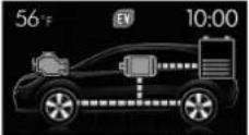 ZOM0383 ZOM0383 | Whendrivingonly bythelectricmotorpower |
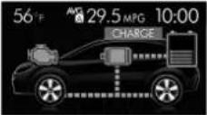 ZOM0384 ZOM0384 | Whenchargingthe highvoltagebat-terywiththere-generativebrakes |
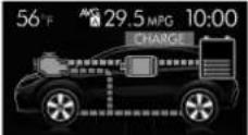 ZOM0385 ZOM0385 | Whenchargingthe highvoltagebat-terywhiledriving usingtheengine power |
| DisplayStatus | |
 | Whenchargingthe highvoltagebat-terybyusingthe enginepower whilethevehicleis stopped |
 | Whenthereisno energycurrent |
1 2  | Remaininghigh voltagebattery poweris (1)low (2)high |
1 2  | Operating/stop-pingoftheengine (1)Whilestopped (illuminatedin gray) (2)Whileoperat-ing(illuminatedinor-ange) |

Inaddition, if awarningormalfunctionis detected in the hybridsystem, an interruptionscreen will be displayed on the multifunction display. Fordetails, refer to "Interruptionscreen" 3-36.
NOTE
●Highvoltagebatterypowerisconsumedmorethanusualwhendriving onlyusingtheelectricmotorpowerforalongtime.
●Highvoltagebatterypowerisconsumedmorethanusualwhenrepeatedlydrivingonlyusingtheelectric motorpowercontinuously.Thereis notaproblemespecially,however avoidstop-and-godrivingasmuchas possiblebymethodssuchaschecking trafficreportsbeforeyoustartdriving.
•The indicator of the remaining high voltage battery power may show empty when the remaining power is extremely
low.However,thisdoesnotindicatea malfunction.
| 100 | |
| 100 | 100 |
| 100 | 100 |
| 100 | 100 |
| 100 | 100 |
| 100 | 100 |
| 100 | 100 |
| 100 | 100 |
| 100 | 100 |
| 100 | 100 |
| 100 | 100 |
| 102 | 102 |
| 102 | 102 |
| 102 | 102 |
| 102 | 102 |
| 102 | 102 |
| 102 | 102 |
| 104 | 104 |
| 104 | 104 |
| 104 | 104 |
| 104 | 104 |
| 104 | 104 |
| 106 | 106 |
| 106 | 106 |
| 106 | 106 |
| 106 | 106 |
| 106 | 106 |
| 108 | 108 |
| 108 | 108 |
| 108 | 108 |
| 108 | 108 |
| 108 | 108 |
| 110 | 110 |
| 110 | 110 |
| 110 | 110 |
| 110 | 110 |
| 112 | 112 |
| 112 | 112 |
| 112 | 112 |
| 112 | 112 |
| 99 | 99 |
Tableofcontents
| Seat,seatbeltandSRSairbags | 1 |
| Keysanddoors | 2 |
| Instrumentsandcontrols | 3 |
| Climatecontrol | 4 |
| Audio | 5 |
| Interiorequipment | 6 |
| Startingandoperating | 7 |
| Drivingtips | 8 |
| Incaseofemergency | 9 |
| Appearancecare | 10 |
| Maintenanceandservice | 11 |
| Specifications | 12 |
| ConsumerinformationandReportingsafetydefects | 13 |
| Index | 14 |
Illustratedindex
Exterior

1)Enginehood(page11-7)
2) Wiperswitch(page3-86)
3)Headlightswitch(page3-79)
4)Replacingbulbs(page11-40)
5)Moonroof(page2-37)
6)Roofrails(page8-13)
7)Outsidemirror(page3-96)
8)Doorlocks(page2-5)
9)Tirepressure(page11-24)
10) Flattires(page9-4)
11)Snowtires(page8-10)
12)Foglightswitch(page3-84)
13)Tie-downhooks(page9-18)
14)Towinghook(page9-18)

1) Rearwindowdefogger(page3-96)
2) Fuelfillerlidandcap(page7-3)
3)Childsafetylocks(page2-32)
4)Tie-downhole(page9-18)
5) Reargate(page2-36)
6) Towinghook(page9-18)
-CONTINUED-
Interior
▼Passengercompartmentarea

1) Lower anchorages for child restraint system (page 1-32)
2) Seatbelt(page1-11)
3)Frontseat(page1-2)
4)Rearseat(page1-7)

1) Powerwindows(page2-32)
2)Doorlocks(page2-5)
3)Outsidemirrorswitch(page3-96)
4)Glovebox(page6-5)
5)Frontpowersupplysocket(page6-7)
6)Selectlever(page7-14)
7) Parkingbrakelever(page7-28)
8) Cupholder(page6-6)
9) Centerconsole(page6-5)
-CONTINUED-
Instrumentpanel

1) Illumination brightness control (page3-83)
2) VehicleDynamicsControlOFFswitch (page7-26)
3) Combinationmeter(page3-8)
4) Multifunctiondisplay(page3-32)
5) Multifunction display control switches (page3-32)
6) Hazardwarningflasherswitch(page3-7)
7)Audio(page5-1)
8)Climatecontrol(page4-1)
9) Tilt/telescopicsteering(page3-98)
10) Horn(page3-98)
11)SRSairbag(page1-37)
12)Fusebox(page11-38)
13) Hoodlockreleaseknob(page11-7)
Steeringwheel

1)Audiocontrolbuttons(page5-18)
2)Cruisecontrol(page7-33)
3) Shiftpaddle(page7-17)
4) Hands-freeswitches(page5-87)
5)SRSairbag(page1-37)
6) Horn(page3-98)
-CONTINUED-
Lightcontrolandwipercontrollevers/switches

1)Windshieldwiper(page3-85)
2) Mist(page3-86)
3)Windshieldwasher(page3-87)
4) Rearwindowwiperandwasherswitch (page3-87)
5) Wiperintermittenttimecontrolswitch (page3-86)
6) Wipercontrollever(page3-86)
7) Lightcontrolswitch(page3-79)
8) Foglightswitch(page3-84)
9)HeadlightON/OFF/AUTO(page3-79)
10) Headlightflasher High/Low beam change(page3-81)
11)Turnsignallever(page3-82)
■ Combinationmeter
▼U.S.-spec.models

Theillustrationaboveisatypicalexample.Forsomemodels,thecombinationmeter maybeslightlydifferentthanthatshownintheillustration.
1) Tachometer(page3-11)
2) Tripmeterandodometer(page3-10)
3) Selectlever/gearpositionindicator (page3-30)
4)Speedometer(page3-10)
5)Selectknob(page3-8)
6) ECOgauge(page3-12)
7)Fuelgauge(page3-11)
8) TripmeterA/Bselectionandtripmeter resetknob(page3-10)
▼ExceptU.S.-spec.models

Theillustrationaboveisatypicalexample.Forsomemodels,thecombinationmeter maybeslightlydifferentthanthatshownintheillustration.
1) Tachometer(page3-11)
2) Tripmeterandodometer(page3-10)
3) Selectlever/gearpositionindicator (page3-30)
4)Speedometer(page3-10)
5)Selectknob(page3-8)
6) ECOgauge(page3-12)
7) Fuelgauge(page3-11)
8) TripmeterA/Bselectionandtripmeter resetknob(page3-10)
■Warningandindicatorlights
| MarkName | ePage | |
 | Seatbeltwarninglight3-13 | |
| PASSENGER[1CS8] | Frontpassenger's seatbeltwarninglight | 3-13 |
 | SRSairbagsystem warninglight | 3-15 |
| [3A0H] | Frontpassenger's frontalairbagONindicator | 3-15 |
| [14W/2] | Frontpassenger's frontalairbagOFFindicator | 3-15 |
CE | CHECKENGINE warninglight/Malfunctionindicatorlight | 3-15 |
| [BD2C] | Coolanttemperature lowindicatorlight/Coolanttemperature highwarninglight | 3-16 |
 | Chargewarninglight3-17 | |
| [4TH2] | Oilpressurewarning light | 3-17 |
| [TCXG] | Engineoillevelwam-inglight | 3-18 |
| MarkName | Page | |
| AT OIL TEMP | ATOILTEMPwarning light | 3-18 |
| ABS / (ABS) | ABSwarninglight3-20 | |
| BRAKE / (!) | Brakesystemwarning light(red) | 3-21 |
| Dooropenwarning light | 3-22 | |
| AWD | AWDwarninglight3-22 | |
| Powersteeringwarninglight | 3-22 | |
| Hillstartassistwarninglight/Hillstartassist OFFindicatorlight | 3-22 | |
| VehicleDynamics Controlwarninglight/VehicleDynamics Controloperationindicatorlight | 3-23 | |
| VehicleDynamics ControlOFFindicator light | 3-24 | |
| Turnsignalindicator lights | 3-30 |
| MarkName | ePage | |
 | Highbeamindicator light | 3-30 |
 | Automaticheadlight beamlevelerwarning light(ifequipped) | 3-30 |
 | Frontfoglightindicator light(ifequipped) | 3-30 |
 | Accesskeywarning light(ifequipped) | 3-25 |
 | Securityindicatorlight3-29 | |
 | Headlightindicator light | 3-30 |
 | Cruisecontrolindica-torlight | 3-30 |
 | Cruisecontrolsetin-dicatorlight | 3-30 |
 | Lowfuelwarninglight3-22 | |
| [AZ3W] | Lowtirepressure warninglight (U.S.-spec.models) | 3-18 |
 | Windshieldwasher fluidwarninglight | 3-18 |
-CONTINUED-
| MarkName | Page | |
 | HybridFailLamp3-31 | |
 | Pedestrianalertwarninglight | 3-31 |
 | HybridREADYIndicatorLight | 3-31 |
 | EV(ElectricVehicle)modelamp | 3-31 |
Functionsettings
A SUBARU dealer can change the settings of the functions shown in the following table to meet your personal requirements. Contact the nearest SUBARU dealer for details. The settings for some of these functions can be changed using the multi function display. For details, refer to "Multi function display" 3-32.
| ItemFunctionPossiblesettingsDefaultsetting | |||
| AlarmsystemAlarmsystemOperation | Non-operationOperation | ||
| Monitoringstartdelaytime(afterclosureofdoors) | 0seconds/30seconds30seconds | ||
| Impactsensoroperation(onlymodelswithshocksensors(dealeroption)) | Operation/Non-operationNon-operation | ||
| Passivearming(modelswithout"KeylessAccesswithPush-buttonStartsystem") | Operation/Non-operationNon-operation | ||
| Domelightandmaplightsillumination(modelswithmoonroof) | ON/OFFOFF | ||
| Domelightillumination(modelswithoutmoonroof) | |||
| KeylessAccess(ifequipped)HazardwarningflasherOperation/Non-operationOperation | |||
| AudiblesignalOperation/Non-operationOperation | |||
| Audiblesignalvolume | Level1to7 Level5 | ||
| Doorunlockselectionfunction(driver'sdoorunlock) | Driver's door only/All doors Driver's door only | ||
| Doorunlock selection function(reargateunlock) | Reargateonly/Alldoors Reargateonly | ||
| Remotekeylessentrysystem | HazardwarningflasherOperation/Non-operationOperation | ||
| AudiblesignalOperation/Non-operationOperation | |||
| Audiblesignalvolume | Level1to7 Level5 | ||
-CONTINUED-
| ItemFunctionPossiblesettingsDefault | setting | ||
| Keylock-inpreventionKeylock-inpreventionOperation/Non-operationOperation | |||
| Defoggeranddeicersystemformodelswiththeautomaticclimatecontrolsystem | Rearwindowdefogger,outsidemirrordefoggerandwindshieldwiperdeicer | Operationfor15minutes/Continuousoperation | Operationfor15minutes |
| DomelightOperationofdomelight/maplightOFFdelaytimer | OFF/10S/20S/30S30S | ||
| Maplightformodelswithamoon-roof | |||
| Batterydrainagepreventionfunction | Batterydrainagepreventionfunction | Operation/Non-operationOperation | |
| SeatbeltwarningSoundsachimewhiledrivingOperation/Non-operationOperation | |||
| Autoon/offheadlights(ifequipped)Sensitivityoftheoperationoftheautoon/offheadlights | Low/Normal/High/VeryhighNormal | ||
| WelcomelightingfunctionWelcomelightingfunction(whenapproaching) | OFF/30seconds/60seconds/90seconds | 30seconds | |
| Welcomelightingfunction(whenexiting) | OFF/30seconds/60seconds/90seconds | ||
| Reversegearinterlockedrearwiper Reversegearinterlockedrearwiper operation | Operation/Non-operationU.S.-spec.models:Non-operationOthermodels:Operation | ||
| One-touchlanechanger | Operationoftheone-touchlanechanger | Operation/Non-operationOperation | |
Seat, seatbelt and SRS airbags
Frontseats....1-2
Forwardandbackwardadjustment....1-3
Recliningtheseatback....1-4
Seat cushion height adjustment (driver's seat) ..... 1-4
Headrestraintadjustment....1-5
Seatheater(ifequipped)....1-6
Safetyprecautions....1-6
Operation....1-6
Rearseats....1-7
Important precautions about the hybrid system....1-8
Armrest(ifequipped)....1-8
Headrestraintadjustment....1-8
Foldingdowntherearseatback....1-10
Seatbelts....1-11
Seatbelt safety tips.... 1-11
EmergencyLockingRetractor(ELR) 1-12
AutomaticLockingRetractor/EmergencyLocking Retractor(ALR/ELR)....1-12
Seatbeltwarninglightandchime 1-13
Fasteningtheseatbelt 1-13
Seatbeltmaintenance....1-20
Frontseatbeltpretensioners 1-20
Seatbeltwithshoulderbeltpretensioner 1-20
Seatbeltwithshoulderbeltandlapbelt pretensioners....1-22
Systemmonitors....1-23
System servicing 1-23
Precautionsagainstvehiclemodification....1-24
Childrestraintsystems.... 1-24
Wheretoplaceachildrestraintsystem....1-25
Choosing a child restraint system.... 1-27
InstallingchildrestraintsystemswithALR/ELR seatbelt 1-27
Installingaboosterseat.... 1-31
Installationofchildrestraintsystemsbyuseof lowerandtetheranchorages(LATCH)....1-32
Toptetheranchorages....1-36
*SRSairbag(SupplementalRestraint Systemairbag)....1-37
General precautions regarding SRSairbag system 1-38
Components....1-44
SUBARUadvancedfrontalairbagsystem....1-46
SRSsideairbagandSRScurtainairbag.... 1-56
SRSairbagsystemmonitors.... 1-63
SRSairbagsystemservicing....1-64
Precautionsagainstvehiclemodification....1-65
Frontseats

WARNING
●Neveradjusttheseatwhiledrivingtoavoidlosingcontrolofthe vehiclewhichcanresultinpersonalinjury.
- Beforeadjustingtheseat,make surethehandsandfeetofrear seatpassengersandcargoare clearoftheadjustingmechanism.
- Afteradjustingtheseat, pushit slightlytomakesureitissecurelylocked. If theseatisnot securelylocked, it may move or theseatbeltmay not operate properly.
- Donotputobjectsunderthefront seats. They may interferewith frontseatlockingandcausean accident. You should, however, storetheflattirerepairkitunder thedriver'sseat. When storing theflattirerepairkit, always secure it with Velcro. Otherwise, it will not remain stationary and it may interferewith driver'sseat lockingandcauseanaccident.
- Seatbeltsprovidemaximumre-
straintwhentheoccupantsits wellbackanduprightintheseat. Toreducetheriskofsliding undertheseatbeltinacollision, thefrontseatbacksshouldbe alwaysusedintheuprightposi- tionwhilethevehicleisrunning. lfthefrontseatbacksarenot usedintheuprightpositionina collision,theriskofslidingunder thelapbeltandofthelapbelt slidingupovertheabdomenwill increase,andbothcanresultin seriousinternalinjuryordeath.
•The SRSairbagsdeploywith considerablespeedandforce. Occupantswhoareoutofproper positionwhentheSRSairbag deployscouldsufferveryserious injuries.Because the SRSairbag needsenoughspacefordeployment,thedriversshouldalways situprightandwellbackinthe seatasfarfromthesteering wheelaspracticalwhilestill maintainingfullvehiclecontrol andthefrontpassengershould movetheseatasfarbackas possibleandsituprightandwell backintheseat.

natural_image
Illustration of two children sitting in a car seat, one wearing a seatbelt and the other holding a belt (no text or symbols)100082

WARNING
Putchildrenin therearseatproperly restrainedatalltimes.TheSRS airbagdeployswithconsiderable speedandforceandcaninjureorevenkillchildren,especiallyifthey arenotrestrainedorimproperly restrained.Becausechildrenare lighterandweakerthanadults,their riskofbeinginjuredfromdeploy-mentisgreater.Forthatreason,we stronglyrecommendthatALLchildren(includingthoseinchildseats andthosethathaveoutgrownchild restraintdevices)sitintheREAR seatproperlyrestrainedatalltimes inachildrestraintdeviceorina seatbelt,whicheverisappropriate
forthe child's age, height and weight. SecureALL types of child restraint devices (including forward facing child seat) in the REAR seats at all times.
NEVERINSTALLAREARWARDFA- CINGCHILDSEATINTHEFRONT SEAT.DOINGSORISKSSERIOUS INJURYORDEATHTOTHECHILD BYPLACINGTHECHILD'SHEAD TOOCLOSETOTHESRSAIRBAG.
According to accident statistics, children are safer when properly restrained in therearseating positions than in the front seating positions. For instructions and precautions concerning childrestraints systems, refer to "Childrestraints systems" 1-24.

natural_image
Diagram showing a hand holding a circular object with internal lines, no text or symbols present101778

WARNING
Donotletrearpassengersresttheir feetbetweenthefrontseatback and seatcushion.Doingsomayleadto defectiveoperationofthefollowing systemsandcouldresultinserious injury.
•Occupantdetectionsystem
•SRSsideairbag
- Seatheater(ifequipped)
■Forwardandbackwardadjustment

Pulltheleverupwardandslidetheseatto thedesiredposition. Thenreleasethe leverandtrytomovetheseatback and forth to make sure that it is securely locked intoplace.
■ Recliningtheseatback

Pulltherecliningleverupandadjustthe seatbacktothedesiredposition.Then releasetheleverandmakesurethe seatbackissecurelylockedintoplace. Theseatbackplacedinareclinedposition canspringbackupwardwithforcewhen theleverispulled.Whileoperatingthe levertoreturntheseatback,holdthe seatbacklightlysothatitmayberaised backgradually.

natural_image
Illustration of a person seated in a car seat using a seatbelt device, with no visible text or symbols.WARNING
Topreventthepassengerfromslidingundertheseatbeltintheeventofacollision,alwaysputtheseatbackintheuprightpositionwhilethevehicleisinmotion.Also,donotplaceobjectssuchascushionsbetweenthepassengerandtheseatback.Ifyoudoso,theriskofslidingunderthelapbeltandofthelapbeltslidingupovertheabdomenwillincrease,andbothcanresultinseriousinternalinjuryordeath.
■ Seatcushionheightadjustment(driver'sseat)

1) Whentheleverispusheddown, the seat islowered. 2) Whentheleverispulledup, theseat rises.
Theheightoftheseatcanbeadjustedby movingtheseatcushionadjustmentlever upanddown.
■Headrestraintadjustment

WARNING
●Neverdrivethevehiclewiththe headrestraintsremovedbecause theyaredesignedtoreducethe riskofseriousneckinjuryinthe eventthatthevehicleisstruck fromtherear.Also,neverinstall theheadrestraintstheopposite wayround.Doingsowillprevent theheadrestraintsfromfunctioningasintended.Therefore, whenyouremovetheheadrestraints,youmustreinstall all headrestraintscorrectlytoprotectvehicleoccupants.
- Alloccupants, including the driver, should not operate a vehicle or sitinavehole's seat until the headrestraints are placed in their proper positions in order to minimize risk of neck injury in the event of acrash.
Theheadrestraintsforthedriver'sseat andfrontpassenger'sseatareadjustable inthefollowingways.
▼Headrestraintheightadjustment

1) Headrestraint
2) Releasebutton
Eachheadrestraintshouldbeadjustedso thatthecenteroftheheadrestraintis closesttothetopoftheoccupant'sears.
Toraise:
Pulltheheadrestraintup.
Tolower:
Push the head restraint down while pressing there lease button on the top of these at back.
Toremove:
Whilepressingthereleasebutton, pullout theheadrestraint.
Toinstall:
Installtheheadrestraintintotheholesthat
arelocatedonthetopoftheseatbackuntil theheadrestraintlocks.
▼Headrestraintangleadjustment

natural_image
Diagram of a mechanical device with a curved arrow indicating rotation, labeled '101574' at bottom (no text or symbols on diagram itself)The angle of the head restraint can be adjusted in several steps. While maintaining as suitable driving posture, adjust the head restraint to a position where the back of your head is as close to the head restraint as possible.
Totilt:
Tilttheheadrestraintbyhandtothe preferredposition.Aclickwillbeaudible whentheheadrestraintislocked.
Toreturn:
Tilttheheadrestraintonceasfarforward asitcango. Theheadrestraintwill automaticallyreturntothefullyupright position. Then, adjusttheheadrestraint
-CONTINUED-
againtothepreferredangle.
Seatheater(ifequipped)
Theseatheaterisequippedinthefront seats.
Theseatheateroperateswhentheignition switch is either in the "ACC" or "ON" position.
■ Safetyprecautions

CAUTION
- Thereisapossibilitythatpeople withdelicateskinmaysuffer slightburnsevenatlowtemperaturesiftheyusetheseatheater foralongperiodoftime.When usingtheheater,alwaysbesure towarnthepersonsconcerned.
- Donotputanythingontheseat whichinsulatesagainstheat, suchasablanket,cushion,or similaritems.Thismaycausethe seatheatertooverheat.
NOTE
Useoftheseatheaterforalongperiod oftimewhilethehybridsystemisnot runningcancausebatterydischarge.
Operation

1)HI-Rapidheating
2)LO-Normalheating
3)Off
A) Left-handside
B) Right-handside
Toturnontheseatheater, push the "LO" or "HI" positionontheswitch, as desired, depending on the temperature.
Selectingthe "HI" positionwillcausethe seattoheatupquicker.
Toturnofftheseatheater, lightlypress the oppositesideofthecurrentposition.
The indicator located on the switch willuminates when these at theater is in operation. Whenthe vehicle's interior is warmed enough before you leave the vehicle, besuretoturn the switch off.
Rearseats

natural_image
Line drawing of a person seated in a car seat with a belt buckle (no text or symbols)
WARNING
Seatbelts provide maximum restraint when the occupants sit well back and upright in these seat. Donot put cushions or any other materials between occupants and seat backs or seat cushions. If you doso, the risk of sliding under the lap belt and of the lap belts sliding up over the abdomen will increase, and both can result in serious internal injury or death.

natural_image
Simple line drawing of a person sitting on the ground next to stacked boxes, with a no-rope symbol in the background (no text or symbols on the diagram itself)
WARNING
Neverstackluggageorothercargo higherthanthetopoftheseatback becauseitcouldtumbleforwardand injurepassengersintheeventofa suddenstoporaccident.
■ Important precautions about the hybridsystem

natural_image
Technical line drawing of a car gear shift lever assembly (no text or symbols)Highvoltagebatteryairintake

CAUTION
Thehighvoltagebatteryairintakeis locatednexttotherearseatonthe left.Conformtothefollowinginstructionstopreventoverheatingof thehighvoltagebatteryormalfunctionofthehybridsystem.
- Donotputanyobjectsnearthe highvoltagebatteryairintake.
- Cleanthehighvoltagebatteryair intakeperiodicallytopreventit fromclogging.
•Itisimportantthatnoliquidsor
anyothersubstancesorobjects beallowedtoentertheairintake. Pleaseadvisepassengersinthis areatousecarearoundtheair intaketopreventanydebrisfrom entering.
- Ifwateroranyobjectsenterit, it may malfunction. When large amount of waterorany objects enterit, contact your SUBARU dealer for inspection.
Armrest(ifequipped)

natural_image
Line drawing of a car seatbelt with a black arrow indicating clockwise motion (no text or symbols)Tolowerthearmrest, pullonthetopedge of thearmrest.

WARNING
Toavoidseriousinjury, passengers must never be allowed to sit on the center arm rest while the vehicle is in motion.
■Headrestraintadjustment
Boththerearwindowsideseatsandthe rearcenterseatareequippedwithhead restraints.

WARNING
●Neverdrivethevehiclewiththe headrestraintsremovedbecause theyaredesignedtoreducethe riskofseriousneckinjuryinthe eventthatthevehicleisstruck fromtherear.Therefore,when youhaveremovedtheheadrestraints, you must reinstall all headrestraintstoprotectivevehicle occupants.
- Allooccupants, including the driver, should not operate a vehicle or sitin a vehicle's seat until the headrestraints are placed in their proper positions in order to minimize risk of neck injury in the event of a crash.
▼Rearwindowssideseatingposition

1) Headrestraint
2) Releasebutton
Toremove:
Whilepressingthereleasebutton, pullout theheadrestraint.
Toinstall:
Installtheheadrestraintintotheholesthat arelocatedonthetopoftheseatbackuntil theheadrestraintlocks.
▼Rearcenterseatingposition

CAUTION
The headrestraint is not intended to be used in theretracted position. Beforesitting on theseat, raise the headrestraint to the extended position.

1) Incorrect(retractedposition)
2) Correct(extendedposition)

1) Headrestraint
2) Releasebutton
Toraise:
Pulltheheadrestraintup.
Tolower:
Pushtheheadrestraintdownwhile pressingthereleasebuttononthetopof theseatback.
Toremove:
Whilepressingthereleasebutton, pullout theheadrestraint.
Toinstall:
Installtheheadrestraintintotheholesthat arelocatedonthetopoftheseatbackuntil theheadrestraintlocks.
Whentherear-centerseatingpositionis occupied, raisetheheadrestrainttothe
-CONTINUED-
extendedposition. Whentherearcenter seatingpositionisnotoccupied, lowerthe headrestrainttoimprovearwardvisibility.
■ Foldingdowntherearseat-back

WARNING
- When you fold down these seat-back, check that there are no passengers or objects on the reseat. Not doings ocreates arisk of injury or property damage if these seat backs suddenly folds down.
●Neverallowpassengerstoride onthefoldedrearseatbackorin thecargoarea.Doingsomay resultinseriousinjuryordeath. - Securealobjectsandespecially longitemsproperlytoprevent themfrombeingthrownaround insidethevehicleandcausing seriousinjuryduringasudden stop,asuddensteeringmaneuverorarapidacceleration.

Lockreleaseknob
1) Unlocked
2)Locked
A) Unlockingmarkerinred

WARNING
Whenyoureturntheseatbacktoits originalposition,checkthatthe unlockingmarkeronthelockreleaseknobisnotvisible.Also, shaketheseatbackslightlytoconfirm that it is securely fixed in place. Iftheseatbackisnotsecurelyfixed in place, the seatback may suddenly folddownintheeventofsudden braking,orobjectsmaymoveout fromthecargoarea,whichcould causeseriousinjuryordeath.


WARNING
When the seatback is returned to its original position, observe the following precautions. Failure to do so may lead to serious injury or an
accidentbecausetheoperationefficiencyoftheseatbeltisinhibited.
•Theseatbeltshouldnotpass behindthesecuringhookfor theseatback.
•The seatbelt should not be caught in these seatback and it should be fully visible.

Unlocktheseatbackbypullingthelock releaseknobandthenfoldtheseatback down.
Toreturntheseatbacktoitsoriginal position,raisetheseatbackuntillocks intoplaceandmakesurethattheunlockingmarkeronthelockreleaseknobisno longervisible.
Seatbelts
■Seatbeltsafetytips
WARNING
- Allpersonsinthevehicleshould fastentheirseatbeltsBEFORE thevehiclestartstomove. Otherwise, the possibility of serious injurybecomesgreaterinthe eventofasuddenstoporaccident.
- All belts should fit snugly in order to providefullrestraint. Loose fittingbeltsarenotaseffectivein preventingorreducinginjury.
- Eachseatbelt is designed to support only one person. Never use a single belt for two or more persons—even children. Otherwise, in an accident, serious injury or death could result.
-Replace all seat belt assemblies including retractors and attaching hardware worn by occupants of vehiclelethathas been a serious accident. The entire assembly should be replaced even if damage is not obvious. - Put children in the rear seat
properlyrestrained atall times. TheSRSairbagdeployswith considerablespeedandforce andcaninjureorevenkillchildren,especiallyiftheyarenot restrained orimproperlyrestrained.Becausechildrenare lighterand weakerthanadults, their risk ofbeinginjuredfrom deploymentisgreater.Forthat reason,westronglyrecommend thatALL children(including thoseinchild seatsandthose thathaveoutgrownchildrestraintdevices)sitintheREAR seatproperlyrestrainedatall timesinachildrestraintdevice orinaseatbelt,whicheveris appropriateforthechild'sheight andweight.
SecureALLtypesofchildre- straintdevices(includingfor- wardfacing childseats)in the REARseatsatalltimes.
NEVERINSTALLAREARWARD FACINGCHILDSEATINTHE FRONTSEAT.DOINGSORISKS SERIOUSINJURYORDEATHTO THECHILDBYPLACINGTHE CHILD'SHEADTOOCLOSETO THESRSAIRBAG.
According to accident statistics,
-CONTINUED-
childrenaresaferwhenproperly restrainedintherearseating positionsthaninthefrontseatingspositions.Forinstructions and precautionsconcerningthe childrestraintsystem,referto "Childrestraintsystems" 1-24.
Yourvehicleisequippedwithacrash sensinganddiagnosticmodule,whichwill recordtheuseoftheseatbeltbythefront passengerwhenanyoftheSRSfrontal, sideandcurtainairbagsdeploy.
▼Infantsorsmallchildren
Useachildrestraintsystemthatis suitableforyourvehicle.Referto"Child restraintsystems" 1-24.
Children
Ifachildistoobigforachildrestraint system,thechildshouldsitintherearseat andberestrainedusingtheseatbelts. Accordingtoaccidentstatistics,children aresaferwhenproperlyrestrainedinthe rearseatingpositionsthaninthefront seatingpositions.Neverallowachildto standuporkneelontheseat.
If the shoulder portion of the belt crosses the face or neck, mov the child clos to the belt buckle to help provide a good shoulder belt fit. Care must be takento
securely placethelapbeltaslowas possible on the hips and not on the child's waist. If the shoulder portion of the belt cannot be properly positioned, a child restraintsystem should be used. Never placethes shoulder belt under the child's armor behind the child's back.
▼Expectantmothers

natural_image
Line drawing of a person seated in a car seat, wearing a medical device (no text or symbols)Expectantmothersalsoneedtousethe seatbelts. They should consult the doctor for specific recommendations. Thelapbelt should beworn securely and as low as possible over the hips, not over the waist.
EmergencyLockingRetractor(ELR)
Thedriver'sseatbelthasanEmergency LockingRetractor(ELR).
The emergency locking retractor allows normal body movement but theretractor locks automatically during as sudden stop, impactorify up pull the belt very quickly out of theretractor.
■AutomaticLockingRetractor/EmergencyLockingRetractor(ALR/ELR)
Eachpassenger'sseatbelthasanAutomaticLockingRetractor/EmergencyLockingRetractor(ALR/ELR).TheAutomaticLockingRetractor/EmergencyLockingRetractornormallyfunctionsasanEmergencyLockingRetractor(ELR).TheALR/ELRhasanadditionallockingmode, "AutomaticLockingRetractor(ALR) mode",intendedtosecureachildrestraint system.
TheALRmodefunctionsasfollows. Whenteseatbeltisoncedrawnout completelyandisthenretractedeven slightly,theretractorlockstheseatbeltin thatpositionandtheseatbeltcannotbe extended.Asthebeltisrewinding,clicks willbeheardwhichindicatetheretractor functionsasanALR.Whenteseatbeltis
retractedfully, the ALR mode is canceled and the ELR mode is restored.
Whensecuringachildrestraintsystemon therearseatsbyusingaseatbelt,the seatbeltmustbechangedovertothe AutomaticLockingRetractor(ALR)mode. Forinstructionsonhowtoinstallthechild restraintsystemusingaseatbelt,referto "Installingchildrestraintsystemswith ALR/ELRseatbelt" 1-27.
Whenthechildrestraintsystemisremoved, makesurethattheretractoris restoredtotheEmergencyLockingRetractor(ELR)modebyallowingtheseat-belttoretractfully.
■ Seatbeltwarninglight andchime

Referto"Seatbeltwarninglightand chime"\~3-13.
■ Fasteningtheseatbelt
WARNING
●Neveruseabeltthatistwistedor reversed.Inanaccident,thiscan increasetheriskorseverity of injury.
- Keep thelap beltaslowas
possibleonyourhips.Inacoll- sion,this spreads theforce ofthe lapbeltoverstrongerhipbones insteadof acrosstheweaker abdomen.
- Seatbeltsprovidemaximumrestraintwhentheoccupantsits wellbackanduprightintheseat. Toreducetheriskofsliding undertheseatbeltinacollision, thefrontseatbacksshouldbe alwaysusedintheuprightpositionwhilethevehicleisrunning. Ifthefrontseatbacks arenot usedintheuprightpositionina collision, theriskofsliding under thelapbeltandofthelapbelt slidingupovertheabdomenwill increase,andbothcanresultin seriousinternalinjuryordeath.
- Donotputcushionsoranyother materials betweenoccupants andseatbacksorseatcushions. Ifyoudoso,theriskofsliding underthelapbeltandofthelap beltslidingupovertheabdomen willincrease,andbothcanresult in serious internalinjury or death.

natural_image
Illustration of a person seated in a car seat during a seatbelt exercise (no text or symbols present)WARNING
Neverplacetheshoulderbeltunder thearmorbehindtheback. Ifan accidentoccurs, this can increase theriskorseverity of injury.
CAUTION
Metallicpartsoftheseatbeltcan becomeveryhotinavehiclethat hasbeenclosedupinsunnyweather;theycouldburnanoccupant.Do nottouchsuchhotpartsuntilthey cool.
▼Frontseatbelts
- Adjust theseat position according to the following procedure.
Driver'sseat: Adjusttheseatbacktothe uprightposition.Movetheseatasfarfrom thesteeringwheelaspracticalwhilestill maintainingfullvehiclecontrol.
Frontpassenger'sseat:Adjusttheseat-backtotheuprightposition.Movetheseat asfarbackaspossible.
2.Sitwellbackintheseat. - Pickupthetongueplateandpullthe beltoutslowly.Donotletitgettwisted.If thebeltstopsbeforereachingthebuckle, returnthebeltslightlyandpullitoutmore slowly.Ifthebeltstillcannotbeunlocked, letthebeltretractslightlyaftergivingita strongpull,thenpullitoutslowlyagain.

natural_image
Illustration of a person adjusting a seatbelt, showing hands and a belt (no text or symbols)- Insertthetongueplateintothebuckle untilyouhearaclick.

natural_image
Illustration of a person adjusting a car seatbelt with a curved arrow indicating force (no text or symbols)- Tomakethelapparttight, pullupon theshoulderbelt.
- Placethelapbeltaslowaspossible onyourhips, notonyourwaist.
Adjustingthefrontseatshoulder beltanchorheight

natural_image
Diagram showing two mechanical assembly steps with arrows indicating motion, no text or symbols presentTheshoulderbeltanchorheightshouldbe adjustedtothepositionbestsuitedforthe driver/frontpassenger.Alwaysadjustthe anchorheightsothattheshoulderbelt passesoverthemiddleoftheshoulder withouttouchingtheneck.
Toraise:
Slidetheanchorup.
Tolower:
Pullthereleaseknobandslidetheanchor down.
Pulldownontheanchortomakesurethat itislockedinplace.

WARNING
Whenwearingtheseatbelts, make suretheshoulderportionofthe webbingdoesnotpassoveryour neck.Ifitdoes,adjusttheseatbelt anchortoalowerposition.Placing theshoulderbeltovertheneckmay resultinneckinjuryduringsudden brakingorinacollision.
∇Unfasteningtheseatbelt

natural_image
Illustration of a person adjusting a seatbelt using a tool (no text or symbols present)Pushthebuttononthebuckle. Beforeclosingthedoor,makesurethat thebeltsareretractedproperlytoavoid catchingthebeltwebbinginthedoor.
▼Rearseatbelts(exceptrearcenter seatbelt)
- Sitwellbackintheseat.
- Pickupthetongueplateandpullthe beltoutslowly.Donotletitgettwisted.If thebeltstopsbeforereachingthebuckle, returnthebeltslightlyandpullitoutmore slowly.Ifthebeltstillcannotbeunlocked, letthebeltretractslightlyaftergivinga strongpullonit,thenpullitoutslowly again.

natural_image
Illustration of a person's seatbelt being adjusted for a piece, showing hands and a belt (no text or symbols)- Insertthetongueplate into the buckle until you hear a click.

natural_image
Illustration of a person adjusting a shoulder belt, showing hands and a tool (no text or symbols present)- Tomakethelapparttight, pullupon theshoulderbelt.
- Placethelapbeltaslowaspossible onyourhips, notonyourwaist.
∇Unfasteningtheseatbelt

natural_image
Illustration of a medical procedure showing hands holding a tool or device, with no visible text or symbols.Pushthebuttononthebuckle.
Beforeclosingthedoor, makesure that the beltsareretractedproperlytoavoid catchingthebeltwebbinginthedoor.
▼Rearcenterseatbelt

1) Centerseatbelttongueplate
2) Connector(tongue)
3) Connector(buckle)
4) Centerseatbeltbuckle


WARNING
Fasteningtheseatbeltwiththewebbingtwistedcanincreasetheriskor severityofinjuryinanaccident. Whenfasteningthebeltafteritis pulledoutfromtheretractor,especiallywheninsertingtheconnector'stongueplateintothemating buckle(onright-handside),always check that the webbing is not twisted.

natural_image
Illustration of a person seated in a car seat, wearing a seatbelt (no text or symbols)100109

WARNING
- Besuretofastenbothtongue platestotherespectivebuckles. Iftheseatbeltisusedonlyasa shoulderbelt(withtheconnector'stongueplatenotfastenedto theconnector'sbuckleonthe right-handside),itcannotproperlyrestrainthewearerinpositioninanaccident,possibly resultinginseriousinjuryor death.
•Theheadrestraintisnotintended tobeusedatthelowestposition. Beforesittingontheseat,raise theheadrestrainttotheextendedposition. Otherwise,in anaccident,seriousinjuryor deathcouldresult.

natural_image
Diagram of a mechanical component with an upward arrow and base mount, no text or symbols present- Raisetheheadrestrainttotheextendedposition.Donotremovethehead restraint.

natural_image
Mechanical diagram showing a car seatbelt buckle assembly with an arrow indicating direction (no text or symbols present)- Removethetongueplatefromthebelt holderontherightsideofthecargoarea andpullouttheseatbeltslowly.

natural_image
Illustration of a hand using a seatbelt to lift a seat, with an inset showing the same seatbelt component (no text or symbols present)- Afterdrawing out these at belt, pass it through the belt guide as follows: First insert one edge of the belt into the open gap in the belt guide; then slid therest of the belt in, so that the whole belt fits inside.

natural_image
Illustration of hands fastening a car seatbelt with a downward arrow indicating compression (no text or symbols)- After confirming that the webbing is not twisted, insert the connector (tongue) attached at the webbing end into the buckle on the right-hand side until a click is heard.
Ifthebeltstopsbeforereachingthe buckle, returnthebeltslightlyandpullit outmoreslowly. Ifthebeltstillcannotbe unlocked, letthebeltretractslightlyafter givingitastrongpull, thenpullitoutslowly again.

natural_image
Line drawing of a person wearing a seatbelt, seated with hands near the neck (no text or symbols)- Insert the center seat belt tongue plate into the center seat belt buckle marked "CENTER" on the left-hand side until it clicks.

natural_image
Illustration of a person adjusting a belt buckle, showing force application and adjustment (no text or symbols)-
Tomakethelapparttight, pullupon theshoulderbelt.
-
Placethelapbeltaslowaspossible onyourhips, notonyourwaist.
∇Unfasteningtheseatbelt

natural_image
Illustration of a hand holding a belt buckle, showing the angle and location (no text or symbols)Pushthereleasebuttonofthecenter seatbeltbuckle(onthelefthandside)to unfastentheseatbelt.
NOTE
Whentheseatbackisfoldeddownfor greatercargoarea,itisnecessaryto disconnecttheconnector.

natural_image
Illustration of hands using a tool to adjust or install a component, no text or symbols present- Insertatongueplateorotherhard pointedobjectintotheslotintheconnector(buckle)ontheright-handsideand pushitin. Theconnector(tongue)plate willthendisconnectfromthebuckle.

natural_image
Mechanical assembly diagram showing two steps of a seatbelt buckle adjustment, with no text or symbols present.- Allowtheretractororollupthebelt. You should hold the webbing and guide it back into the retractor while it is rolling up. Insert the connector (tongue) into the beltholder.

natural_image
Diagram of a car seatbelt buckle assembly with no visible text or symbols
CAUTION
- Donotallowtheretractoroll up the seatbelt too quickly. Otherwise, themetaltongue platesmayhitagainstthetrim, resultingindamagedtrim.
●Havetheseatbeltfullyrolledup sothatthetongueplatesare neatlystored.Ahangingtongue platecanswingandhitagainst thetrimduringdriving,causing damagetothetrim.
■ Seatbeltmaintenance
Tocleantheseatbelts, useamildsoap andlukewarmwater. Neverbleachordye thebeltsbecausethiscouldseriously affecttheirstrength.
Inspecttheseatbeltsandattachments includingthewebbingandallhardware periodicallyforcracks,cuts,gashes, tears,damage,looseboltsorwornareas. Replacetheseatbeltsevenifonlyminor damageisfound.

CAUTION
- Keepthebeltsfreeofpolishes, oils,chemicalsandparticularly batteryacid.
●Neverattempttomakemodificationsor changesthat willprevent theseatbeltfromoperatingproperly.
Frontseatbeltpretensioners
Thedriver'sandfrontpassenger'sseat-beltshaveaseatbeltpretensioner.The seatbeltpretensionersaredesignedtobe activatedintheeventofanaccident involvinga moderate tosevere frontal andsidecollisionandrolloveraccident.
■ Seatbeltwithshoulderbelt pretensioner
NOTE
Thissectionisapplicabletothedriver'sseatbelt.

natural_image
Illustration of a person seated in a car seatbelt with directional arrows indicating movement (no text or symbols)Thepretensionersensoralsoservesas follows.
●SRSfrontalairbagsensor
●Frontdoorimpactsensor
- Rolloversensor
If the sensor detects acertain predetermined amount off forced during frontal or side collisions or rollover accidents, the front seat belt is quickly drawn back in by theretractor to take up the lack so that the belt more effectively restrains the driver.
When a seatbelt pretensioner is activated, anoperatingnoisewillbeheardanda smallamountofsmokewillbereleased. Theseoccurrencesarenormalandnot harmful. Thissmokedoesnotindicatea fireinthevehicle.
Oncetheseatbeltpretensionerhasbeen activated, theseatbeltretractorremains locked. Consequently, theseatbeltcannot bepulledoutandretractedandtherefore mustbereplaced.
NOTE
- Seatbeltpretensionersarenotdesignedtoactivateinminorimpactsor inrearimpacts.
- In cases of rollover accidents, as the curtain airbags deploy, the driver's side seatbelt pretensioner and front passenger's sideshoulderbeltpretensioner areactivatedsimultaneously.
• In cases of frontal collisions, the
followingcomponentswilloperatesimultaneously.
-Seatbeltpretensionerfordriver
-Seatbeltpretensionerforfront passenger
-SRSfrontalairbagfordriver
-SRSfrontalairbagforfrontpassenger*
-SRScurtainairbags(bothsides) (ifanoffsetfrontalcollisionoccurs)
*:Thisdoesnotoperateiftheoccupant detectionsystemdeactivatesairbagoperation.Fordetails,referto "Front passenger'sSRSfrontalairbag": 1-46 •Incasesofsidecollisions,the followingcomponentswilloperatesi- multaneously.
-SRScurtainairbag(impacted side)
-SRSsideairbag(impactedside) (when both the satellites a fingsensor and any of the center pillar impacts sensors/frontdoor impact sensor sense an impact force)
-Seatbeltpretensionerfordriver (when both the satellitesafingsensor and the driver's side frontdoor impacts sensorsense an impact force)
-Seatbeltpretensionerforfront passenger(shoulderbeltpreten-
sioneronly)(whenboththesatellite safingsensorandthefrontpassenger'ssidefrontdoorimpactsensor senseanimpactforce)
- Pretensionersaredesignedtofunctiononaone-time-onlybasis.Inthe eventthatapretensionerisactivated, boththedriver'sandfrontpassenger's seatbeltretractorassemblieshould bereplacedonlybyanaauthorized SUBARUdealer.Whenreplacingseat-beltretractorassemblies,useonly genuineSUBARUparts.
- lfeitherfrontseatbeltdoesnot retractorcannotbepulledoutdueto amalfunctionoractivationofthe pretensioner,contactyourSUBARU dealerassoonaspossible.
- If the front seat belt retractor assembly or surrounding area has been damaged, contact your SUBARU dealer as soon as possible.
- Whenyouselyourvehicle,weurge youtoexplaintothebuyerthatithas seatbeltpretensionersbyalertingthe buyertothecontentsofthissection.

WARNING
• To obtain maximum protection, the occupant should sit in an upright position with their seat-
beltsproperlyfastened. Referto "Seatbelts" 1-11.
- Donotmodify, removeorstrike thefrontseatbeltretractorassembliesorsurroundingarea. Thiscouldresultinaccidental activationoftheseatbeltpretensionersorcouldmakethesysteminoperative,possiblyresultinginseriousinjury. Seatbelt pretensionershavenouser-serviceableparts. Forrequiredservicingoffrontseatbeltretractors equippedwithseatbeltpretensioners, consultyourSUBARU dealer.
- Whendiscardingfrontseatbelt retractorassembliesorscrappingtheentirevehicledueto collisiondamageorforother reasons,consultyourSUBARU dealer.
■ Seatbeltwithshoulderbelt andlapbeltpretensioners
NOTE
Thissectionisapplicabletothefront passenger'sseatbelt.

1) Seatbeltretractorassembly (shoulder beltpretensioner)
2)Lapbeltpretensioner
On the front passenger's side, the shoulder belt pretensioner issupplemented by alap belt pretensioner, which is located at the base of the center pillar. Likewise should be belt pretensioner, the lap belt pretensioner instantaneously pulls in the belt to eliminate slack if certain level offrontal collision force is detected. As a result, these at belt restrain the front seat occupant more effectively.
Whenaseatbeltpretensionerisactivated, anoperatingnoisewillbeheardanda smallamountofsmokewillbereleased. Theseoccurrencesarenormalandnot harmful. Thissmokedoesnotindicatea fireinthevehicle.
Oncetheseatbeltpretensionerhasbeen activated, theseatbeltpretensionerremainslocked. Consequently, theseatbelt cannotbepulledoutandretractedand thereforemustbereplaced.
NOTE
- Seatbeltpretensionersarenotdesignedtoactivateinminorimpactsor inrearimpacts.
- Whenarolloveraccidentoccurs, the lapbeltpretensionerdoesnotactivate; however, asthecurtainairbagsdeploy, theshoulderbeltpretensionerisactivated. Atthistime, thedriver'sside seatbeltpretensionerandpassenger's sideshoulderbeltpretensioneractivatesimultaneously.
- Incasesoffrontalcollisions, the followingcomponentswilloperate simultaneously.
-Seatbeltpretensionerfordriver
-Seatbeltpretensionerforfront passenger
-SRSfrontalairbagfordriver
-SRSfrontalairbagforfrontpas-
senger\*
-SRScurtainairbags(bothsides) (ifanoffsetfrontalcollisionoccurs)
*:Thisdoesnotoperateiftheoccupant detectionsystemdeactivatesairbagoperation.Fordetails, refer to"Front passenger'sSRSfrontalairbag" -1-46
- Incasesofsidecollisions, the following components will operatesimultaneously.
-SRScurtainairbag(impacted side)
-SRSsideairbag(impactedside) (when both the satellites a fingsensor and any of the center pillar impacts sensors/frontdoor impact sensors sense an impact force)
-Seatbeltpretensioner fordriver (when both the satellitesafingsensor and the driver's side frontdoor impactsensorsense an impact force)
-Seatbeltpretensionerforfront passenger(shoulderbeltpretensioneronly)(whenboththesatellite safingsensorandthefrontpassenger'ssidefrontdoorimpactsensor senseanimpactforce)
- Pretensionersaredesignedtofunctiononaone-time-onlybasis.Inthe eventthatapretensionerisactivated, boththedriver'sandfrontpassenger's
seatbeltretractorassemblies should bereplaced only by an authorized SUBARU dealer. When replacing seat-beltretractor assemblies, use only genuine SUBARU parts.
- If either front seat belt does not retractor cannot be pulled out due to malfunction or activation of the pretensioner, contact your SUBARU dealer as soon as possible.
- If the front seat belt retractor assembly or surrounding area has been damaged, contact your SUBARU dealer as soon as possible.
- Whenyouselyourvehicle,weurge youtoexplaintothebuyerthatithas seatbeltpretensionersbyalertingthe buyertothecontentsofthissection.

WARNING
- Toobtainmaximumprotection, theoccupantsshouldsitinan uprightpositionwiththeirseatbeltsproperlyfastened.Referto "Seatbelts" 1-11.
- Donotmodify, removeorstrike thefrontseatbeltretractorassembliesorsurroundingarea. This could result in accidental activation of these seat belt pretensioners or could make the system
teminoperative,possiblyresultinginserious injury. Seatbelt pretensionershavenouser-serviceable parts. For required servicing off front seat belt retractors equipped with seat belt pretensioners, consult your SUBARU dealer.
- Whendiscardingfrontseatbelt retractor assemblies or scrappingtheentirevehicledueto collisiondamageorforother reasons,consultyourSUBARU dealer.
Systemmonitors
Adiagnosticsystemcontinuallymonitors thereadinessoftheseatbeltpretensioner whilethevehicleisbeingdriven. The seatbeltpretensionerssharethecontrol modulewiththeSRSairbagsystem. Therefore,ifanymalfunctionoccursina seatbeltpretensioner,theSRSairbag systemwarninglightwillilluminate.For details,referto“SRSairbagsystem monitors”1-63.
■Systemservicing

WARNING
- Whendiscardingaseatbeltretractorassemblyorscrapping theentirevehicledamagedbya collision,consultyourSUBARU dealer.
- Tamperingwithordisconnecting thesystem'swiringcouldresult in accidental activation of the seatbeltpretensionerand/or SRSairbagorcouldmakethe systeminoperative,whichmay resultinseriousinjury.Donot useelectricaltestequipmenton anycircuitrelatedtotheseatbelt pretensionerandSRSairbag systems.Forrequiredservicing oftheseatbeltpretensioner,consultyournearestSUBARUdealer.

CAUTION
ThesensorsandSRSairbagcontrol modulesarelocatedinthefollowing locations.
- Frontsubsensors:onboththe rightandleftsideatthefrontof
-CONTINUED-
thevehicle
●Frontdoorimpactsensors:on bothfrontdoors
- Satellitesafingsensor: underthe rearcenterseat
- SRSairbagcontrolmodule(includingtheimpactsensors):underthecenteroftheinstrument panel
If you needs service or repair in those areas or near the front seat belt retractors, havethework performed by your authorized SUBARU dealer.
NOTE
If the front part of the vehicle is damaged in an accident to the extent that these seat belt pretensioner does not operate, contact your SUBARU dealer as soon as possible.
■Precautionsagainstvehicle modification
AlwaysconsultyourSUBARUdealerif youwanttoinstallanyaccessorypartsto yourvehicle.

CAUTION
Donotperformanyofthefollowing modifications.Suchmodifications caninterferewithproperoperation oftheseatbeltpretensioners.
- Attachmentofanyequipment (bushbar,winches,snowplow, skidplate,etc.)otherthangenuineSUBARUaccessorypartsto thefrontend.
-Modificationofthesuspension systemorfrontendstructure. - Installationofatireofdifferent sizeandconstructionfromthe tiressspecifiedonthevehicle placardattachedtothedriver's doorpillarorspecifiedforindividualvehiclemodelsinthisOwner'sManual.
Childrestraintsystems

natural_image
Illustration of a child seated in a car seat, no text or symbols present101656
Infantsandsmallchildrenshouldalways beplacedinaninfantorchildrestraint systemintherearseatwhileridinginthe vehicle.Youshoulduseaninfantorchild restraintsystemthatmeetsFederalMotor VehicleSafetyStandardsorCanada MotorVehicleSafetyStandards,iscompatiblewithyourvehicleandisappropriateforthechild'sageandsize.Allchild restraintsystemsaredesignedtobe securedinvehicleseatsbylapbeltsor the lap belt portion of a lap/shoulder belt (exceptthosedescribedin"Installation of childrestraintsystemsbyuse of lowerand tetheranchorages(LATCH)" 1-32). Childrencouldbeendangeredan accidentiftheirchildrestraintsarenot
properlysecuredinthevehicle.When installingthechildrestraintsystem,carefullyfollowthemanufacturer'sinstructions.
According to accident statistics, children aresafer when properly restrained in the rearseating position than in the front seating positions.
AllU.S.statesandCanadianprovinces requirethatinfantsandsmallchildrenbe restrainedinanapprovedchildrestraint systematalltimeswhilethevehicleis moving.

natural_image
Illustration of a child and adult sitting in a car seat, viewed from the side (no text or symbols)
WARNING
Neverletapassengerholdachild onhisorherlaporinhisorher armswhilethevehicleismoving. Thepassengercannotprotectthe
childfrominjuryinacollision, because the child will be caught between the passenger and objects inside the vehicle.
Additionally, holding a child in your lapar arms in the front seat exposes that child to another serious danger. Sincethe SRS air bag deploys with considerable speed and force, the child could be injured or even killed.

natural_image
Illustration of two children interacting with a vehicle, no text or symbols present
WARNING
Childrenshouldbeproperlyre- strainedatalltimes.Neverallowa childtostandup,ortokneelonany seat.Unrestrainedchildrenwillbe thrownforwardduringsuddenstop
orinanaccidentandcanbeinjured seriously.
Additionally, childrenstandingupor kneelingonorinfrontofthefront seatareexposedanotherserious danger. SincetheSRSairbagdeployswithconsiderablespeedand force, thechildcouldbeinjuredor evenkilled.
■Wheretoplaceachildre- straintsystem
The following are SUBARU's recommendations on where to place each child restraint system in your vehicle.

100127
A:Frontpassenger'sseat
Youshouldnotinstallachildrestraint system(includingaboosterseat)dueto thehazardtochildrenposedbythe passenger'sairbag.
B: Rearseat, window-sideseating positions
Recommended positions for all types of childrestraintsystems.
In these positions, Automatic Locking Retractor/Emergency Locking Retractor (ALR/ELR) seat belts and lower anchorages (bars) are provided for installing achildrestraintsystem.
Sometypesofchildrestraintsmightnotbe abletobesecuredfirmlyduetoprojection oftheseatcushion.
Inthisseatingposition,youshoulduse onlyachildrestraintsystemthathasa bottombasethafitssnuglyagainstthe contoursoftheseatcushionandcanbe securelyretainedusingtheseatbelt.
C: Rearseat, centerseating position
The ALR/ELRseatbeltandanupper anchorage(tetheranchorage)are provided in this position.
Sometypesofchildrestraintsmightnotbe abletobesecuredfirmlyduetoprojection oftheseatcushion.
Inthisseatingposition,youshoulduse
onlyachildrestraintsystemthathasa bottombasethatfitssnuglyagainstthe contoursoftheseatcushionandcanbe securelyretainedusingtheseatbelt.
When you install a child restraint system in therearse at's center seating position, raise the center head restraint.
Loweranchorages(bars)forwindow-side seatingpositionsmaybeusedforaseat inthecenterseatingpositionifachild restraintsystemmanufacturer'sinstruc-tionspermitandspecifyusinganchorsas farapartasthoseinthisvehicle.
Ifachildrestraintsystemisnotcorrectly fixedinplace(forexample,ifachild restraintsystemcanbemovedmorethan 1inch(2.5cm)fromsidetoside),you shouldinstallthechildrestraintsystemin arearseat,window-sideseatingposition.

WARNING
- Evenwith advancedairbags, children can be seriously injured by the airbag. Put children in the rearseat properly restrained at all times. The SRSairbag deploys with considerable speed and force and can injure even kill children, especially if they are not restrained or improperly restrained. Because children are
lighterandweakerthanadults, theirriskofbeinginjuredfrom deploymentisgreater.
Forthatreason,besuretose-cureALLtypesofchildrestraint devices(including forward facing childseats)intheREARseatsat alltimes.Youshouldchoosea restraintdevicewhichisappropriateforthechild'sage,height andweight.Accordingtoaccidentstatistics,childrenaresafer whenproperlyrestrainedinthe rearseatingpositionsthaninthe frontseatingpositions.
- Donotuseloweranchorages (bars)foraseatinthecenter seatingpositionunlesssachild restraintsystemmanufacturer's instructionspermitandspecify usinganchorsspacedasfar apartasthoseinthisvehicle.

natural_image
Medical illustration of a patient undergoing a medical procedure in a car seatbelt (no text or symbols present)
WARNING
SINCE YOUR VEHICLE IS EQUIPPEDWITHAPASSENGER'S SRSAIRBAG,NEVERINSTALLA REARWARD FACING CHILD SAFETYSEATINTHEFRONTPASSENGER'SSEAT.DOINGSORISKS SERIOUSINJURYORDEATHTO THECHILDBYPLACINGTHE CHILD'SHEADTOOCLOSETO THESRSAIRBAG.
■ Choosingachildrestraint system

natural_image
Line drawings of three different car seats (no text or symbols)Chooseachildrestraintsystemthatis appropriateforthechild'sageandsize (weightandheight)inordertoprovidethe childwithproperprotection.Thechild restraintsystemshouldmeetallapplic- ablerequirementsofFederalMotorVehi- cleSafetyStandardsfortheUnitedStates orofCanadaMotorVehicleSafetyStan- dards for Canada. It can be identified by lookingforthelabelonthechildrestraint systemorthemanufacturer'sstatementof compliance in the document attached to thesystem.
Also it is important for you to make sure that the child restraint system is compatible with the vehicle in which it will be used.
■Installingchild restraint systems with ALR/ELR seatbelt

WARNING
- Childrestraintsystemsandseat-beltscanbecomehotinavehicle thathasbeenclosedupinsunny weather;theycouldburnasmall child.Checkthechildrestraint system before youplace achild init.
- Do not leave an unsecured child restraint system in your vehicle. Unsecured child restraint systemscanbethrownaroundinsideof thevehicle inasudden stop, turn or accident; they can strikeandinjurevehicleoccupantsaswellasresultinserious injuriesordeathtothechild.

CAUTION
- When you install a child restraint system, follow the manufacturer's instruction supplied with it. After installing the child restraintsystem, check to ensure that it is held securely in position. If it is not held tight and
-CONTINUED-
secure, the danger of your child suffering personal injury in the event of an accident maybe increased.
- Wheninstallingachildrestraint systemintherearcenterseating position,setbothseatbacksto theoriginalposition.Otherwise, thechildrestraintsystemcannot besecurelyrestrained,which mayresultindeathorserious injuriesintheeventofsudden stop,suddensteeringmaneuver oranaccident.
▼Installingarearwardfacingchild restraint

- Placethechildrestraintsysteminthe
rearseatingposition.
-
Runthelapandshoulderbeltthrough oraroundthechildrestraintsystem followingtheinstructionsprovidedbyits manufacturer.
-
Insertthetongueplateintothebuckle untilyouhearaclick.
-
Runthelapandshoulderbeltthrough oraroundthechildrestraintsystem followingtheinstructionsprovidedbyits manufacturer.
- Insertthetongueplateintothebuckle untilyouhearaclick.

natural_image
Illustration of a person's seatbelt being adjusted with a tool, showing the angle and direction (no text or symbols)-
Takeuptheslackinthelapbelt.
-
Pullout these at belt fully from the retractortochangetheretractor over from the Emergency Locking Retractor (ELR) to the Automatic Locking Retractor (ALR) function. Then, allow the belt to rewind into the retractor. Asthe belt is rewinding, click will be heard which indicate the retractor functions as ALR.

natural_image
Illustration of a person performing a shoulder press or grip technique with directional arrows indicating movement (no text or symbols)- Pushandpullthechildrestraint systemforwardandfrom side to sideto checkifitisfirmlysecured.Sometimesa childrestraintcanbemorefirmlysecured bypassingitdownintotheseatcushion andthentighteningtheseatbelt.
7.Pullattheshoulderportionofthebelt to confirm that it cannot be pulled out (ALR properlyfunctioning).

natural_image
Illustration of a car seatbelt buckle being lifted, showing the seatbelt being inserted (no text or symbols present)- Toremovethechildrestraintsystem, pressthereleasebuttonontheseatbelt buckleandallowthebelttoretract completely. Thebeltwillreturntothe ELRmode.

WARNING
NEVERINSTALLAREARWARDFA- CINGCHILDSEATINTHEFRONT PASSENGER'S S E A T . D O RISKSSERIOUSINJURYORDEATH TOTHECHILDBYPLACINGTHE CHILD'SHEADTOOCLOSETOTHE SRSAIRBAG.
NOTE
Whenthechildrestraintsystemisno longerinuse,removeitandrestorethe ELRfunctionoftheretractor.That functionisrestoredbyallowingthe seatbelttoretractfully.
▼Installingforward facingchildrestraint

WARNING
Beforeinstallingachildrestraint system, besuretoconfirm that the seatbackissecurelylockedinto place. Otherwise, in an accident, seriousinjuryordeathcouldresult.
- Shaketheseatbackslightlytoconfirm thatitissecurelylockedintoplace.
- It is possible to check whether the seatbackislockedvisually. Ifthe seatback is locked into place, the red coloredunlockingmarkerwhichis attachedtothebottomofthelock releaseknobisinvisible. Fordetails, refer to "Foldingdown therearseat-back" 1-10.
- Preparetherearseatheadrestraint whereachildrestraintsystemisintended tobeinstalledinthefollowingway.
- When a child restraint system is
installedonthewindow-side seating position,removetherearseathead restraint.Fordetails, referto"Head restraintadjustment"1-8. Storetheheadrestraintin thecargo area. Avoid placing the head restraint inthepassengercompartmentto preventitfrombeing thrownaround in the passenger compartment in a suddenstoporasharpturn.
- When a child restraint system is installed on the rear center seating position, raisetherearseathead restraint totheextendedposition. Do notremovetheheadrestraint. For details, refer to "Rear center seating position"→1-9.
- Place the child restraint system in the rearseating position.

WARNING
When youintend toinstalla child restraintsystemontherearcenter seatingposition,if the childrestraint systemdoesnotfitsnuglyagainst the contours of the rear center seat cushion, install the child restraint system on the window-side seating positiontobesafe.Fordetails,refer to "Where to place a child restraint system" 1-25.
-CONTINUED-

- Runthelapandshoulderbeltthrough oraroundthechildrestraintsystem followingtheinstructionsprovidedbyits manufacturer.
-Whenachildrestraintsystemis installedontherearcenterseating position, passtherearcenterseatbelt throughthebeltguideproperly. For details, refer to "Rearcenterseatbelt" 1-16.
- Insertthetongueplateintothebuckle untilyouhearaclick.

natural_image
Diagram of a car seatbelt with hand placement and belt, showing no text or symbols6.Takeuptheslackinthelapbelt.
- Pullouttheseatbeltfullyfromthe retractortochangetheretractoroverfrom theEmergencyLockingRetractor(ELR) totheAutomaticLockingRetractor(ALR) function.Then,allowthebelttorewind intotheretractor.Asthebeltisrewinding, clickswillbeheardwhichindicatethe retractorfunctionsasALR.

natural_image
Diagram of a car seatbelt with hand placement and motion arrows indicating force (no text or symbols)-
Before having a child sit in the child restraint system, try to move it back and forth and right and left to check if it is firmly secured. Sometimes a child restraint system can be more firmly secured by pushing it down into these at cushion and thentightening these at belt.
-
Pullattheshoulderportionofthebelt to confirm that it cannot be pulled out (ALR properlyfunctioning).
-
Latchthetoptetherhookontothe tetheranchoragethatislocatedbehind therearseatandtightenthetoptether firmly.Foradditionalinstructions,referto "Toptetheranchorages" 1-36.

natural_image
Illustration of a car seatbelt buckle being inserted, with an inset showing the insertion step (no text or symbols present)- Toremovethechildrestraintsystem, pressthereleasebuttonontheseatbelt buckleandallowthebelttoretract completely. Thebeltwillreturntothe ELRmode.
If you have installed child restraint system for therear center seating position, when you remove the child restraint system, these belt may not be restored to the ELR mode even if these seat belt is retracted. In this case, lower the head restraint to the retracted position to allow these belt to retract moreover. The seat belt will return to the ELR mode.
Remember that the head restraint is not intended to be used at the lowest position (retracted position). Therefore, when the rear center seatis occupied (including
whenachildrestraintsystemisinstalled) nexttime,besuretoraisethehead restrainttotheextendedposition.
NOTE
Whenthechildrestraintsystemisno longerinuse,removeitandrestorethe ELRfunctionoftheretractor.That functionisrestoredbyallowingthe seatbelttoretractfully.
■Installingaboosterseat
WARNING
●Childrestraintsystemsandseat-beltscanbecomehotinvehicle thathasbeenclosedupinsunny weather;theycouldburnasmall child.Checkthechildrestraint systembeforeyouplaceachild init.
- Donotleaveanunsecuredchild restraintsysteminyourvehicle. Unsecuredchildrestraintsystems can be thrown around insideofthevehicle inasudden stop,turnoraccident;theycan strikeandinjurevehicleoccupantsaswellasresultinserious injuriesordeathtothechild.

CAUTION
When you install a child restraint system, follow the manufacturer's instruction supplied with it. After installing the child restraint system, check to ensure that it is held securely in position. If it is no held tight and secure, the danger of your child suffering personal injury in the event of an accident maybe increased.

natural_image
Illustration of a child sitting in a car seat with a close-up of the seatbelt (no text or symbols)- Placetheboosterseatintherear seatingpositionandsitthechildonit.The childshouldsitwellbackonthebooster seat.
- Runthelapandshoulderbeltthrough oraroundtheboosterseatandthechild
-CONTINUED-
followingtheinstructionsprovidedbyits manufacturer.
- Insertthetongueplate into the buckle until you hear a click. Take care not to twist these at belt.
Makesuretheshoulderbeltispositioned acrossthecenterofchild'sshoulderand thatthelapbeltispositionedaslowas possibleonthechild'ships.

natural_image
Illustration of a child wearing a seatbelt, with an inset showing the same seatbelt (no text or symbols present)- Toremovetheboosterseat, press the release button on these seat belt buckle and allow the belttoretract.

WARNING
- Neveruseabeltthatistwistedor reversed.Inanaccident,thiscan increasetheriskorseverity of injurytothechild.
- Neverplacetheshoulderbelt underthechild'sarmorbehind thechild'sback.Ifanaccident occurs,thiscanincreasetherisk orseverityofinjurytothechild.
- Theseatbeltshouldfitsnuglyin ordertoprovidefullrestraint. Loosefittingbeltsarenotas effectiveinpreventingorreducinginjury.
- Placethelapbeltaslowas possibleonthechild'ships.A high-positionedlapbeltwillin- creasetheriskofslidingunder thelapbeltandofthelapbelt slidingup over theabdomen, and bothcanresultinseriousinternalinjuryordeath.
- Makesurethe shoulderbelt is positionedacrossthecenterof child's shoulder. Placing the shoulderbeltovertheneckmay resultinneckinjuryduringsuddenbrakingorinacollision.
■ Installationofchildrestraint systemsbyuseoflowerand tetheranchorages(LATCH)

WARNING
- Childrestraintsystemsandseat-beltscanbecomehotin avehicle thathasbeenclosedupinsunny weather;theycouldburnasmall child.Check thechild restraint systembeforeyouplaceachild init.
- Donotleaveanunsecuredchild restraintsysteminyourvehicle. Unsecuredchildrestraintsystemscanbethrownaroundinsideofthevehicleinasudden stop,turnoraccident;theycan strike and injure vehicle occupantsaswellasresultinserious injuriesordeathtothechild.

CAUTION
- When you install a child restraint system, follow the manufacturer's instruction supplied with it. After installing the child restraintsystem, check to ensure that it is held securely in posi-
tion.lfitisnotheldtightand secure,thedangerofyourchild sufferingpersonalinjuryinthe eventofanaccidentmaybe increased.
- Wheninstallingachildrestraint systemintherearcenterseating position,adjustbothseatbacks atthesameangle. Otherwise,the childrestraintsystemcannot be securelyrestrained,causing deathorseriousinjuriesinthe eventofsuddenstop,sudden steeringmaneuveroranaccident.
▼Lowerandtetheranchorages

Sometypesofchildrestraintsystemscan
beinstalledontherearseatofyour vehiclewithoutuseoftheseatbelts.Such childrestraintsystemsaresecuredtothe designatedanchoragesprovidedonthe vehiclebody.Thelowerandtetheran-choragesaresometimesreferredtoasthe LATCH system (Lower Anchors and TethersforCHildren).

Your vehicle is equipped with four lower anchorages(bars)andthreeupperanchorages(tetheranchorages)foraccommodatingsuchchildrestraintsystems.
Loweranchorages

natural_image
Line drawing of a car backseat with seat covers and mounting brackets (no text or symbols)Theloweranchorages(bars)areused for installingachildrestraintsystemonly on therearseatwindow-sideseatingpositions. Foreachwindow-sideseatingposition, twoloweranchoragesareprovided. Eachloweranchorageislocated where theseatcushionmeetstheseatback.
Tetheranchorages

natural_image
Top-down line drawing of a car backrest with four seats and directional arrows indicating movement (no text or symbols)The tether anchorages (upper anchorages) are provided at the locations shown in the above illustration. For details, refer to "Top tether anchorages" 1-36.
▼Toinstallachildrestraintsystem usinglowerandtetheran-chorages
Toinstallachildrestraintsystemusing lowerandtetheranchorages,performthe followingprocedure.
WARNING
Beforeinstallingachildrestraint system,besuretoconfirmthatthe seatbackissecurelylockedinto place.Otherwise,inanaccident,seriousinjuryordeathcouldresult.
1.Shaketheseatbackslightlytoconfirm thatitissecurelylockedintoplace. -Itispossibletocheckwhetherthe seatbackislockedvisually.Ifthe seatbackislockedintoplace,thered coloredunlockingmarkerwhichis attachedtothebottomofthelock releaseknobisinvisible.Fordetails, refer to"Foldingdowntherearseat-back" 1-10.

natural_image
Line drawing of a car backseat with seatbelt and passenger seat icons, no text or symbols present- You will find marks "at the bottom of therearse seat seats. These marks indicate the position of the lower anchorages (bars).

Removethecoversandlocatethelower anchorages(bars).
- Removetherearseatheadrestraint. Fordetails, referto "Rearwindowsside seatingposition" 1-9.

natural_image
Line drawing of a car seatbelt with a close-up inset showing the bracket detail (no text or symbols)- While following the instruction supplied by the child restraintsystem manufacturer, connect the lower hooks onto the lower anchorages located at "markson the bottom of therearseatback. When the hooks are connected, makes sure the adjacent seat belts are not caught.

natural_image
Line drawing of a car seatbelt buckle with a hand insertion instruction (no text or symbols)5.[Ifyourchildrestraintsystemisofa flexibleattachmenttype(whichuses tetherbeltstoconnectthechildrestraint systemproperlytotheloweranchorages)] Whilepushingthechildrestraintintothe seatcushion,pullbothleftandrightlower tetherbeltsuptosecurethechildrestraint systemfirmlybytakinguptheslackinthe belt.
6.Latchthetoptetherhookontothe tetheranchoragethatislocatedbehind therearseatandtightenthetoptether firmly.Foradditionalinstructions,referto "Top tether anchorages" 1-36.

natural_image
Line drawing of a car seat with hand placement and motion arrows indicating movement (no text or symbols)- Beforeseatinga child inthechild restraintsystem, trytomoveitback and forthandrightandlefttoverifythatitis heldsecurelyinposition.
- Toremovethechildrestraintsystem, followthereverseproceduresofinstallation.
If you have any question concerning this type of child restraintsystem, ask your SUBARU dealer.
■ Toptetheranchorages
Yourvehicleisequippedwiththreetop tetheranchoragessothatachildrestraint systemhavingatoptethercan be installedintherearseat.Wheninstalling achildestraintsystemusingtoptether, proceedingsfollows,whileobservingthe instructionsbythechildrestraintsystem manufacturer.
Sinceatoptethercanprovideadditional stabilitybyofferinganotherconnection betweenachildrestraintsystemandthe vehicle, werecommendthatyouuseatoptetherwheneveroneisrequiredoravailable.
▼Anchoragelocation

1) Forleftseat
2)Forcenterseat
3) Forrightseat
Threeupperanchoragesareinstalledon thebacksideoftherearseatback.
▼Tohookthetoptether

CAUTION
- Exceptforthecenterseating position,removetheheadrestraintwhenmountingachild restraintsystem. Otherwise,it might be possible that the top tethercannotbefastenedtightly.
- For the center seating position, raisethe center head restraint to the extended position when mounting a child restraint system. Otherwise, it will be impossible to these seat belt guide that is attached to the head restraint correctly. The seat belt guide is essential for routing the belt webbing at the center seating position. For information about using these seat belt guide, referto "Rearcenter seat belt" - 1-16.

natural_image
Technical illustration of a mechanical component with a separate inset showing a gear mechanism (no text or symbols)- Attachthetoptetherhooktothe appropriateupperanchorage.
Forthecenterseatingposition,route thetoptetherundertheheadrestraintas illustratedbelow.

1) Seatbeltguide
2) Seatbeltofthecenterseatingposition
3) Toptether
- Tightenthetoptethersecurely.
PleasecontactyourSUBARUdealerif youhaveanyquestionregardingthe installationofachildrestraintsystem.
\*SRSairbag(Supplemental RestraintSystemairbag)
*SRS:Thisstandsforsupplementalrestraintsystem. Thisnameisusedbecausetheairbagsystemsupplementsthe vehicle'sseatbelts.
Yourvehicleisequippedwithasupplementalrestraintsysteminadditiontoa lap/shoulderbeltateachfrontseating positionandeachrearwindow-sideseatingpositions. Thesupplementalrestraint system(SRS)consistsofsevenairbags.
Theconfigurationsareasfollows.
- Driver's and front passenger's frontal airbags
- Driver's and front passenger's side airbags
- Curtain airbags (for driver, front passenger, and window-side rear passengers)
- Kneeairbagfordriver
TheseSRSairbagsaredesignedonly asasupplementtotheprimaryprotec-tionprovidedbytheseatbelt.
Thesystemalsocontrolsfrontseatbelt pretensioners. Foroperationinstructions and precautions concerning these seatbelt pretensioner, refer to "Front seatbelt pretensioners" 1-20.
-CONTINUED-
■ General precautions regarding SRSairbagsystem

WARNING
- To obtain maximum protection in the event of an accident, the driver and all passengers in the vehicles should always wear seat belts when the vehicle is moving. The SRSair bag is designed only to be as supplement to the primary protection provided by these seat belt. It does not eliminate the need to fast these seat belts. In combination with these seat belts, it offers the best combined protection in case of a serious accident.
Not wearing seat belt increases the chance of severe injury or death in acras heven when the vehicle has the SRSair bag.
For instructions and precautions concerning these seat belts system, refer to "Seatbelts" 1-11.
•TheSRSsideairbagandSRS curtainairbagaredesignedonly tobeasupplementtotheprimary protectionprovidedbytheseat-belt.Theydonot eliminatethe needtofastenseatbelts.Itisalso important towear your seatbelt
tohelpavoidinjuriesthatcan result when an occupant is not seatedinaproperuprightposition.

natural_image
Line drawing of a person seated in a car, holding a steering wheel and belt (no text or symbols)100155

WARNING
•The SRSairbags deploy with considerable speed and force. Occupants who are out of proper position when the SRSairbag deploys could suffer very serious injuries. Because the SRSairbag needs enough space for deployment, the drivers should always sit upright and well back in the seat as far from the steering wheel as practical while still maintaining full vehicle control
and thefront passenger should movetheseatasfarbackas possibleandsituprightandwell backintheseat.

natural_image
Illustration of a person wearing a seatbelt inside a car, with motion lines indicating speed (no text or symbols)
WARNING
- Donotsitorleanunnecessarily closetoeitherfrontdoor. The SRS side airbags are stored in bothfrontseatbacksnextto the door, and they provide protectionbydeployingrapidly(fasterthantheblinkofaneye)inthe eventofasideimpactorfrontal collision. However,the force of SRSsideairbagdeploymentmay causeinjuriesifyourheader other parts of the body are too
closetotheSRSsideairbag.
- Sinceyourvehicleisequipped withSRScurtainairbags,donot sitorleanunnecessarilycloseto thefrontorreardooroneither side.Also,donotputyourhead, armsorhandsoutofthewindow. TheSRScurtainairbagsonboth sidesofthecabinaarestoredin theroofside(betweenthefront pillarandapointbehindtherear quarterglass),andtheyprovide protectionbydeployingrapidly (fasterthantheblinkofaneye)in theeventofasideimpactor frontalcollision.TheSRScurtain airbagsalsodeployintheevent ofarollover.However,theforce ofitsdeploymentmaycause injuriesifyourheadistooclose toit.
- Donotsitorleanunnecessarily closetotheSRSairbag.Because theSRSairbagdeployswith considerablespeed-fasterthan theblinkofaneyee-andforceto protectinhighspeedcollisions, theforceofanairbagcaninjure anoccupantwhosebodyistoo closetoSRSairbag. Itisalsoimportanttowearyour seatbelttohelpavoidinjuries
thatcanresultwhentheSRS airbagcontactsanoccupantnot improperpositionsuchasone thrownforwardduringpre-accidentbraking.
Evenwhenproperlypositioned, thereremainsapossibilitythat anoccupantmaysufferminor injurysuchasabrasionsand bruisesto the face or arms becauseoftheSRSairbagdeploymentforce.

natural_image
Illustration of a person wearing a seatbelt and holding a device, seated in a vehicle (no text or symbols)
WARNING
- Donotrestyourarmoneither frontdoororitsinternaltrim.You couldbeinjuredintheeventof
SRSsideairbagdeployment.
- Donotplaceanyobjectsoveror neartheSRSairbagcoveror betweenyouandtheSRSairbag. IftheSRSairbagdeploys,these objectscouldinterferewithits properoperationandcouldbe propelled inside the vehicle, causing injury.

natural_image
Interior view of a car dashboard and steering wheel (no text or symbols visible)
WARNING
- Donotputanyobjectsoverthe steeringwheelpadanddashboard.IftheSRSfrontalairbag deploys,theseobjectscouldinterferewithitsproperoperation andcouldbepropelledinsidethe
-CONTINUED-
vehicle, causing injury.
- Donotputanyobjectsunderthe driver'ssideoftheinstrument panel.IftheSRSkneeairbag deploys,thoseobjectscouldinterferewithitsproperoperation andcouldbepropelledinsidethe vehicle,causinginjury.
•Thekeymustnotbeattachedto heavy,sharporhardaccessories,oranotherkey.Ifthe SRSkneeairbagdeploys,those objectscouldinterferewithits properoperationandcouldbe propelledinsidethevehicleand causeinjury.

natural_image
Interior view of a car showing a hand holding a seatbelt, with a large 'no' symbol and a small dog icon on the seat (no text or symbols present)
WARNING
Donotattachaccessoriestothe windshield,orfitanextra-widemirror- rovertherearviewmirror.Ifthe SRSairbagdeploys,thoseobjects couldbecomeprojectilesthatcould seriouslyinjurevehicleoccupants.

natural_image
Line drawing of a car seat with a side-mounted device, no text or symbols present
WARNING
- Donotattachaccessoriestothe doortrimorneareitherSRSside airbagsanddonotplaceobjects neartheSRSsideairbags.Inthe eventofSRSsideairbagdeployment,theycouldbepropelled dangerouslytowardthevehicle's
occupantsandcauseinjuries.
- Donotattachahands-freemicrophoneoranyotheraccessoryto afrontpillar,acenterpillar,arear pillar,thewindshield,asidewindow,anassistgrip,oranyother cabinsurfacethatwouldbenear adeployingSRScurtainairbag. Ahands-freemicrophone or otheraccessoryinsuchalocationcouldbepropelledthrough thecabinwithgreatforcebythe curtainairbag,oritcouldprevent correctdeploymentofthecurtain airbag.lneithercase,theresult couldbeseriousinjuries.

natural_image
Line drawing of a hanger with handle and frame, no text or symbols present
WARNING
Donothangcoathangersorother hardorpointedobjectsonthecoat hooks. If such items were hanging on the coathooks during deployment of the SRS curtainairbags, they could cause serious injuries by coming off the coathooks and being thrown through the cabin or by preventing deployment of the curtainairbags.
Beforehangingclothingonthecoat hooks, makesuretherearenosharp objectsinthepockets. Hangclothingdirectlyonthecoathookswithoutusinghangers.

natural_image
Medical illustration of a joint with surgical hardware and a highlighted area (no text or symbols)
WARNING
Donotputanykindofcoveror clothesorotherobjectsovereither frontseatbackanddonotattach labelsorstickerstothefrontseat surfaceonorneartheSRSside airbag. Theycouldpreventproper deploymentoftheSRSsideairbag, reducingprotectionavailabletothe frontseat'soccupant.

natural_image
Illustration of two children sitting in a car seat, one wearing a seatbelt and the other holding a belt (no text or symbols)100082

WARNING
Putchildrenintherearseatproperly restrainedataltimes.TheSRS airbagdeployswithconsiderable speedandforceandcaninjureor
evenkillchildren,especiallyifthey arenotrestrainedorimproperly restrained.Becausechildrenare lighterandweakerthanadults,their riskofbeinginjuredfromdeploy-mentisgreater.
Forthatreason, westronglyrecommend that ALL children (including those in child seats and those that have outgrown child restraint devices) sit in the REAR seat properly restrained at all times in a child restraint device or in a seat belt, whichever is appropriate for the child's sage, height and weight.
SecureALLtypesofchildrestraint devices(includingforwardfacing childseats)intheREARseatsat alltimes.
According to accident statistics, children are safer when properly restrained in therearseating positions than in the front seating positions.
For instructions and precautions concerning the childrestraints system, refer to "Childrestraints systems" 1-24.

natural_image
Illustration of a person lying in a car seatbelt, no text or symbols present
WARNING
NEVERINSTALLAREARWARDFACINGCHILDSEATINTHEFRONT SEAT.DOINGSORISKSSERIOUS INJURYORDEATHTOTHECHILD BYPLACINGTHECHILD'SHEAD TOOCLOSETOTHESRSAIRBAG.

natural_image
Illustration of two children interacting near a table, no text or symbols present
WARNING
Neverallowachildtostandupor kneelonthefrontpassenger'sseat. TheSRSairbagdeployswithconsiderableforceandcaninjureorevenkillthechild.

natural_image
Illustration of a person sitting in a car seat with another child, no text or symbols present
WARNING
Neverholdachildonyourlaporin yourarms.TheSRSairbagdeploys withconsiderableforceandcan injureorevenkillthechild.

natural_image
Illustration of a person sitting in a car seat, holding a vehicle (no text or symbols present)
natural_image
Illustration of a person wearing a backpack and holding a seat, standing beside a vehicle (no text or symbols)
- Neverallowachildtodothe following. -Kneelonanypassenger's
seatfacingthesidewindow
- Wraphis/herarmsaroundthe frontseatseatback
-Puthis/herhead, armsor otherpartsofthebodyoutof thewindow
Intheeventofanaccident,the forceofSRSsideairbagand/or SRScurtainairbagdeployment couldinjurethechildseriously becausehis/herhead,armsor otherpartsothebodyaretoo closetotheSRSsideairbagand/orSRScurtainairbag.
- Since your vehicle is also equipped with a front passenger's SRS frontal airbag, children should be placed in there are seat anyway and should be properly restrained at all times.

CAUTION
- WhentheSRSairbagdeploys, somesmokewillbereleased. This smoke could cause breathingproblemsforpeoplewitha history ofasthma or other breathing trouble. If you or your passengershavebreathingproblems afterSRS airbagdeploys,
getfreshairpromptly.
●AdeployingSRSairbagreleases hotgas. Occupantscouldget burnediftheycomeintodirect contactwiththehotgas.
NOTE
- Whenyousellyourvehicle,weurge youtoexplaintothebuyerthatitis equippedwithSRSairbagsbyalerting thebuyertotheapplicablesectionin thisOwner'sManual. - IftheSRSairbag deploys,fuel supplywillbecutofftoreducetherisk of fire caused by leaking fuel. For detailsaboutrestartingofthehybrid system, refer to "If your vehicle is involvedinanaccident" 9-24.
Components

1) SRSfrontalairbag
2)SRSsideairbag
3)SRScurtainairbag
4)SRSkneeairbag
The SRSairbagsarestowed in the following locations.
Driver's SRSfrontalairbag:inthecenter portionofthesteeringwheel
Frontpassenger'sSRSfrontalairbag: nearthetopofthedashboardunderan "SRSAIRBAG" mark
SRSsideairbag:inthedoorsideofeach frontseatseatbackwhichbearsan"SRS AIRBAG"label
SRScurtainairbag:intheroofside (betweenthefrontpillarandapoint behindtherearquarterglass) "SRSAIRBAG"marksarelocatedatthe topofeachcenterpillarandrearpillar.
SRSkneeairbag:underthesteering column

1) Airbagcontrolmodule(includingimpact sensorandrolloversensor)
2)Frontalairbagmodule(driver'sside)
3) Frontalairbagmodule(frontpassenger's side)
4) Frontsubsensor(left-handside)
5) Frontsubsensor(right-handside)
6)Sideairbagmodule(driver'sside)
7) Sideairbagmodule(frontpassenger's side)
8) Sideairbagsensor(centerpillarleft-hand side)
9) Sideairbagsensor(centerpillarright-handside)
10)Airbagwiring
11) Seatbeltpretensioner(driver'sside)
12) Seatbeltpretensioner(frontpassenger's side)
13) Curtainairbagsensor(rearwheelhouse right-handside)
14) Curtainairbagsensor(rearwheelhouse left-handside)
15) Curtainairbagmodule(right-handside)
16) Curtainairbagmodule(left-handside)
17) Seatbeltbuckleswitch(frontpassenger's side)
18)Kneeairbagmodule(driver'sside)
19) Frontpassenger'soccupantdetection systemsensor
20) Frontpassenger'soccupantdetection controlmodule
21) Frontpassenger'sfrontalairbagONand OFFindicator
22)SRSairbagsystemwarninglight
23)Satellitesafingsensor(undertherear centerseat)
24)Frontdoorimpactsensor(left-handside)
25)Frontdoorimpactsensor(right-hand side)
26)Lapbeltpretensioner(frontpassenger's side)
■ SUBARUadvancedfrontal airbagsystem
YourvehicleisequippedwithaSUBARU advancedfrontalairbagsystemthatcomplieswiththenewadvancedfrontalairbag requirementsintheamendedFederal MotorVehicleSafetyStandard(FMVSS) No.208.
The SUBARUadvancedfrontalairbag systemautomaticallydeterminesthedeploymentforceofthedriver'sSRSfrontal airbagatthetimeofdeploymentaswellas whetherornottoactivatethefront passenger'sSRSfrontalairbagand,if activated,thedeploymentforceofthe SRSfrontalairbagatthetimeofdeployment.
Yourvehiclehaswarninglabelsonthe driver'sandfrontpassenger'ssunvisors beginningwiththephrase "EVEN WITH ADVANCEDAIRBAGS" andatag attachedtotheglovebox lidbeginning withthephrase"EvenwithAdvancedAir Bags".Makesurethatyoucarefullyread theinstructionsonthewarninglabelsand tag.
Alwayswearyourseatbelt. The SUBARU advancedfrontalairbagsystemisa supplementalrestraint systemand must beusedincombinationwithaseatbelt. All occupants should wear a seatbelt or be seatedinanappropriatechildrestraint
system.
ForthelocationsoftheSRSairbags, refer to "Components" 1-44.
Inamoderatetoseverefrontalcollision, the following components deploy.
• SRSfrontalairbagfordriver
• SRSfrontalairbagforfrontpassenger
• SRSkneeairbagfordriver
- SRScurtainairbag* ^1
*1: When an offset frontal collision that is severe enough to deploy the front air bag occurs.
Thesecomponentssupplementtheseat-beltsbyreducingtheimpacttothe occupant'shead,chestandknees.
▼Driver'sSRSfrontalairbag
Thedriver's SRSfrontalairbagusesa dualstageinflator. Theinflatoroperates in differentwaysdependingontheseverity of impact.
Havethesysteminspectedbyyour SUBARUdealer immediatelyif theSRS airbagsystemwarninglightilluminates.
NOTE
Thedriver'sSRSsideairbagandSRS curtainairbagarenotcontrolledbythe SUBARUadvancedfrontalairbagsystem.
▼Frontpassenger'sSRSfrontalair-bag
Thefrontpassenger's SRSfrontalairbag usesadualstageinflator. Theinflator operatesindifferentwaysdependingon theseverityofimpact.
The occupant detection system sensoris installed under these atupholstery and monitor the physique and posture of the front passenger. Using this information, the occupant detection system determines whether the front passenger's SRS frontal airbag should be deployed or not.
The occupant detectionsystem may not inflate the front passenger's SRS frontal airbage even when the driver's SRS frontal airbag deploys. This is normal. In this case, although the front passenger's SRS frontal airbag does not operate, the front passenger's seat belt pretensioner operates with the driver's seat belt pretensioner. For details about these seat belt pretensioner, refer to "Front seat belt pretensioners" 1-20.

CAUTION
Observethe following precautions. Failuretodosomaypreventthe SUBARUadvancedfrontalairbag systemfromfunctioningcorrectly orcausethesystemtofail.
- Donotapplyanystrongimpact tothefrontpassenger'sseat.
- Donotspillliquidonthefront passenger'sseat.Ifliquidis spilled,wipeitoffimmediately.
- Donotremoveordisassemble thefrontpassenger'sseat.
- Donotinstallanyaccessory (suchasanaudioamplifier)other thanagenuineSUBARUaccessoryunderthefrontpassenger's seat.
- Donotplaceanything(shoes, umbrella,etc.)underthefront passenger'sseat.
- Donotputsharpobject(s)onthe seatorpiercetheseatupholstery.
- Donotplaceamagnetnearthe seatbeltbuckle.
If theseatbeltbuckleswitchand/orfront passenger's occupantdetectionsystem have failed, the SRSairbagsystem warninglightwillilluminate. Havethe systeminspectedbyyourSUBARUdeal-erimmediatelyiftheSRSairbagsystem warninglightilluminates.
If your vehicle hassustained impact, this may affect the proper function of the SUBARU advanced frontal air bags system. Haveyourvehicleinspectedatyour SUBARUdealer.Donotusethefront passenger'sseatwhiledrivingthevehicle toyourSUBARUdealer.
NOTE
Thefrontpassenger'sSRSsideairbag and SRScurtainairbagarenotcontrolledbytheSUBARUadvancedfrontalairbagsystem.
▼Passenger'sfrontalairbagONand OFFindicators
Referto"Frontpassenger'sfrontalairbag ONandOFFindicators" 3-15.
▼Occupantdetectionsystem
The occupant detection system sensoris installed under these atupholstery and monitor the physique and posture of the front passenger. Using this information, the occupant detection system determines whether the front passenger's SRS frontal airbag should be deployed or not.
If the front passenger's seat cushion is wet, this may adversely affect the ability of the system to determine deployment. If these account is wet, the front passengers should stop sitting on the front passenger's seat. Wipe off liquid from these immediately, let these eat dry naturally and then check the SRS air bag
systemwarninglightasfollows.

SRSairbagsystemwarninglight
- If the SRSairbagsystemwarninglight illuminates, keep these at dry until the warning light turn soff. If the SRSairbag system warning light stays one even when these athas dried, donotallowanyoneto sit on the front passenger's seat and have the system checked by your SUBARU dealer.
- IftheSRSairbagsystemwarninglight doesnotilluminate, checkthatthefront passenger'sfrontalairbagONandOFF indicatorsworkproperly. Iftheindicators donotworkproperly, donotallowanyone tositonthefrontpassenger'sseat and have the system checked by your SUBARUdealer.

ON/:Frontpassenger'sfrontalairbagON indicator
OFF /:Frontpassenger'sfrontalairbagOFF indicator
Also, if luggageorelectronicdevices are placed on the frontpassenger's seat, this may adversely affect the ability of the system to determined deployment. This may prevent the frontpassenger's frontal airbag ON and OFF indicators from working properly. Check that the indicators work properly.
WhentheOFFindicatorturnsoffandthe ONindicatorilluminates,thefrontpassenger'sfrontalairbagmaydeployduringa collision.Removeluggageandelectronic devicesfromthefrontpassenger'sseat.

CAUTION
Electricaldevices,suchascell phones,laptops,portablemusic players,orelectronicgames,especiallywhenconnectedtotheaccessorypoweroutletandplacedonthe frontpassenger'sseatorusedby thepersonsittinginthefrontpassenger'sseat,mayaffecttheoperationoftheoccupantdetectionsystem.lfeitherofthefollowingsituationsoccurswhenusinganelectronicdeviceinthevehicle,atfirsttry torelocatethatdevicetoavoidit creatinganyinterference.
•TheSRSairbagsystemwarning lightilluminates.
- Thefrontpassenger'sfrontalairbagONandOFFindicatorsoperateerratically.
If the device continues to cause interference, the use of that device in the vehicles should be discontinued.
NOTE
ThisdevicecomplieswithPart18of theFCCRules.Thisdevicemaycause interference.Ifthisdevicecausesinterference,consultthenearestSUBARU
dealer.Also,formaintenanceofthe system,consultthenearestSUBARU dealer.Acopyoftheoriginaldeclarationofconformitycanbefoundin chapter13.
▼Conditionsinwhich frontpassenger'sSRSfrontal airbagisnot activated
The frontpassenger'sSRSfrontal airbag will not be activated when any of the following conditions are met regarding the frontpassenger's seat:
- Theseatisempty.
- Theseatisequippedwithanappropriatechild restraintsystemand aninfant isrestrainedinit.(SeeWARNINGthat follows.)
- Thefrontpassenger'soccupantdetectionsystemismalfunctioning.

WARNING
NEVERINSTALLAREARWARDFACINGCHILDSEATINTHEFRONT PASSENGER'SSEATEVENIFTHE FRONTPASSENGER'SSRSFRONTALAIRBAGISDEACTIVATED.Be suretoinstallitintheREARseatin acorrectmanner.Also,itisstrongly recommendedthatanyforwardfacingchildseatorboosterseatbe
installedintheREARseat, and that evenchildren who have outgrowna child restraints system be also seatedintheREARseat. This is because children sitting in the front passenger's seat may be killed or severely injured should the front passenger's SRS frontal air bag dep- ploy. REAR seats are the safest placefor children.

CAUTION
Whenthefrontpassenger'sseatis occupiedbyaninfantinanappropriatechildrestraintsystem, observethefollowingprecautions. Failuretodosomayinterferewith theproperoperationoftheoccupantdetectionsystem,activating thefrontpassenger'sSRSfrontal airbageeventhoughthatseatis occupiedbytheinfantinthechild restraintsystem.
- Donotplaceanyarticle(includingelectronicdevices)onthe seatotherthantheinfantinthe childrestraintsystem.
- Donotplacemorethanone infantinthechildrestraintsystem.
If the front passenger's frontal airbag ON indicator illuminates and the OFF indicator turnoff even when an infant or small child in a child restraint system (including booster seat)
- Turntheignitionswitchtothe"LOCK" (off)position.
- Removethechildrestraintsystem fromtheseat.
- Byreferring to the child restraint manufacturer's recommendations as well asthechild restraint system installation procedures in "Childrestraintsystems" 1-24, correctly install the child restraint system.
- Turntheignitionswitchtothe"ON" positionandmakesurethatthefront passenger'sfrontalairbagONindicator turns off and the OFF indicator illuminates.
If still the ON indicator remains illuminated whiletheOFFindicatorturnsoff,takethe followingactions.
- Ensure that no article is placed on the seat other than the child restraints system and the child occupant.
- Ensure that the backward-position and seat backoffront passenger's seat are locked into places securely by moving these seat back and forth.
If the ON indicator still remains illuminated whiletheOFFindicatorturnsoffafter takingrelevantcorrectiveactionsdescribedabove,relocatethechildrestraint systemtotherearseatandimmediately contactyourSUBARUdealerforan inspection.
NOTE
When a child who has outgrown a child restraintsystemorasmalladultis seatedinthefrontpassenger'sseat, theSUBARUadvanced frontalairbag systemmayormaynotactivatethe frontpassenger'sSRSfrontalairbag dependingontheoccupant'sseating posture. Children should always wear a seatbelt when sitting in the seat irrespective of whether the airbag is deactivatedoractivated. Ifthefront passenger'sSRSfrontalairbagisactivated (theONindicatorremainsilluminated while the OFF indicator turns off), takethefollowingactions.
- Ensure that no article is placed on these other than the occupant.
IftheONindicatorstillremainsillumi-
-CONTINUED-
natedwhiletheOFFindicatorturnsoff despitethefactthattheactionsnoted abovehavebeentaken,seatthechild/smalladultintherearseatandimmediatelycontactyourSUBARUdealer foraninspection.Evenifthesystem haspassedthedealerinspection,itis recommendedthatonsubsequenttrips thechild/smalladultalwaystakethe rearseat.
Childrenwhohaveoutgrownachild restraintsystemshouldalwayswearthe seatbeltirrespectiveofwhethertheairbag isdeactivatedoractivated.
▼Conditionsinwhichfrontpassenger'sSRSfrontalairbagisactivated
Thefrontpassenger's SRSfrontalairbag will be activated for deployment upon impact when any of the following conditions are met regarding the frontpassenger's seat.
- Whentheseatisoccupiedbyanadult.
- Whencertainitems(e.g.jugofwater) areplacedontheseat.
If the passenger's frontal airbag OFFindicator illuminates and the ON indicator turn soeven whenthe front passenger's seat is occupied by an adult
This can be caused by the adult incorrectly sitting in the front passenger's seat.
- Turntheignitionswitchtothe"LOCK" (off)position.
- Askthefrontpassenger tosetthe seatbacktotheuprightposition,situp straightinthecenteroftheseatcushion, correctlyfastentheseatbelt,positionhis/herlegsoutforward,andadjusttheseat to therearmostposition.
- Turntheignitionswitchtothe "ON" position.
If the OFF indicator remains illuminated while the ON indicator remains off, take the following actions.
- Turntheignitionswitchtothe"LOCK" (off)position.
- Makesurethatthefrontpassenger doesnotuseablanket, seatcushion, seat cover, seatheaterormassager, etc.
- If wearing excessive layers of clothing, the front passengers should remove any unnecessary items before sitting in the front passenger's seat, or should sit in a rearseat.
- Turntheignitionswitchtothe"ON"
positionandwait6secondstoallowthe systemtocompleteself-checking.Followingthesystemcheck,bothindicatorsturnoffor2seconds.Now,theONindicator shouldilluminatewhiletheOFFindicator remainsoff.
IftheOFFindicatorstillremainsilluminatedwhiletheONindicatorremainsoff, asktheoccupanttomovetotherearseat andimmediatelycontactyourSUBARU dealerforaninspection.
Howtocontactthevehiclemanufacturerconcerningmodifications forpersonswithdisabilitiesthat mayaffecttheadvancedairbag system
Changingormovinganypartsofthefront seats,rearseat,seatbelts,frontbumper, frontsideframe,radiatorpanel,instrument panel,combinationmeter,steeringwheel, steeringcolumn,tire,suspensionorfloor panelcanaffecttheoperationofthe SUBARUadvancedairbag system.If youhaveanyquestions,youmaycontact thefollowingSUBARUdistributors.
SubaruofAmerica,Inc.
CustomerDealerServicesDepartment
P.O.Box6000
CherryHill, NJ08034-6000
1-800-SUBARU3(1-800-782-2783)
SubaruHawaii
2850PukoloaStreet, Suite202,
Honolulu, HI96819-4467
808-839-2273
Shen'sCorporationdbaPrestigeAutomobile
491, EastMarineCorpsDrive, Route1
Dededo, Guam96921-6225
671-633-2698
TrebolMotors
P.O.Box11204,SanJuan,PuertoRico
00910
787-793-2828
SubaruCanada, Inc.
ConsumerSupportDepartment
560SuffolkCourt, Mississauga, Ontario
L5R4J7
1-800-894-4212
TherearecurrentlynoSUBARUdistributorsinanyotherU.S.territories.Ifyouare insuchanarea,pleasecontactthe
SUBARUdistributorordealerfromwhich youboughtyourvehicle.
▼Operation

A)Driver'sside
B)Passenger'sside
1)SRSAIRBAGsdeployassoonasacollisionoccurs.
2) After deployment, SRS AIRBAGs start to deflate immediately so that the driver's vision is not obstructed.
The SRSairbagscanfunction only when the ignitionswitchis in the "ON" position.
The SUBARUadvancedfrontalairbag systemisdesignedtodeterminethe activationordeactivationconditionofthe front passenger's SRS frontal airbag dependingonthecharacteristicofitem (s)orpersononthefrontpassenger'sseat monitoredbythefrontpassenger'soccupantdetectionsystemsensor.Forthis reason,onlythedriver'sSRSfrontal airbagmaydeployintheeventofa collision,butthisdoesnotmeanfailure ofthesystem.
If the following sensors detect apredetermined amount off forced during a frontal collision, the control modules send signals to the airbag module(s) (only driver's module or both driver's sand front passenger's modules) instructing the module(s) to inflate the SRS frontal airbag(s).
• thefrontsubsensors
• theimpactsensorsintheairbagcontrol module
Onthedriver'sside, the SRSkneeairbag alsoinflates with the SRSfrontalairbag.
The driver's sandfrontpassenger's SRS frontalairbagsusedualstageinflators. Thetwoinflatorsofeachairbagare triggeredeithersequentiallyorsimultaneously, dependingontheseverity of impact,inthecaseofthedriver'sSRS frontalairbaganddependingonthe severityofimpactandthecharacteristic ofitem(s)orpersonontheseatinthecase ofthefrontpassenger'sSRSfrontal airbag.
Afterdeployment, the SRSairbagimmediately startstodeflatesothatthedriver's visionis not obstructed and the driver's ability to maintain in control of the vehicle is not impaired. The time required from detecting impact to the deflation of the SRSair bag after deployment is shorter than the blink of an eye.
Bothwhenonlythedriver'sSRSfrontal airbagdeploysandthedriver'sandfront passenger'sSRSfrontalairbagsdeploy, thedriver'sandfrontpassenger'sseatbelt pretensionersoperateatthesametime.
WhentheSRSairbagdeplays,asudden, fairlyloudinflationnoisewillbeheard and somesmokewillbereleased. These occurrencesareanormalresultofthe deployment. Thissmokedoesnotindicate afireinthevehicle.

CAUTION
DonottouchtheSRSairbagsystem componentsaroundthesteering wheelanddashboardwithbare handsrightafterdeployment.Doing socancauseburnsbecause the componentscanbeveryhotasa resultofdeployment.
Thedriver's SRSfrontalairbagandfront passenger's SRSfrontalairbagaredesignedasfollows.
- todeployintheeventofanaccident involvingamoderatetoseverefrontal collision
• tofunctiononaone-time-onlybasis
Thedriver's SRSfrontalairbagandfront passenger'sSRSfrontalairbagarenot designedasfollows.
- to deploy in most lesser frontal impacts ^*1
- todeployinmostsideorrearimpacts orinmostroll-overaccidents *2
*1: Because the necessary protection can be achieved by these seat belt alone.
*2: Because deployment of only the driver's SRS frontal airbag or both the driver's sandfront passenger's SRS frontal airbags would not protect the occupant in those situations.
SRSairbagdeploymentdependsonthe levelofforceexperiencedinthepassengercompartmentduringacollision. That leveldiffersfromonetypeofcollisiononto another, anditmayhavenobearingon thevisibledamagedonetothevehicle itself.
Exampleofaccidentinwhichthe driver's/driver'sandfrontpassenger'sSRSfrontalairbag(s) willmostlikelydeploy

natural_image
Line drawing of a car approaching a tree with a broken trunk (no text or symbols)101394
Ahead-oncollisionagainstathickconcretewallatavehiclespeedof12to19 mph(20to30km/h)orhigheractivates onlythedriver'sSRSfrontalairbagorboth driver'sandfrontpassenger'sSRSfrontal airbags. Theairbag(s)willalsobeeactivatedwhenthevehicleisexposedtoa frontalimpactsimilarinfashionand
-CONTINUED-
magnitudeto the collision described above.
Examplesofthetypesofaccidentsinwhichitispossiblethat thedriver's/driver'sandfront passenger'sSRSfrontal airbag(s)willdeploy

natural_image
Two cartoon illustrations showing a car being crashed and moving, with no text or symbols present.Onlythedriver'sSRSfrontalairbagor bothdriver'sandfrontpassenger'sSRS frontalairbagsmaybeactivatedwhenthe vehiclesustainsahardimpactinthe undercarriageareafromtheroadsurface (suchaswhenthevehicleplungesintoa deepditch,isseverelyimpacted or knockedhardagainstanobstacleonthe roadsuchasacurb).
Examples of the types of accidents in which deployment of the driver's/ driver's and front passenger's SRS frontal airbag(s) is unlikely to occur
1

4

natural_image
Top-down diagram of two cars with arrows indicating collision or damage, no text or symbols present2

natural_image
Diagram of a car being struck by a truck, showing impact and collision (no text or symbols)5

natural_image
Top-down line drawing of three cars with a collision accident symbol above (no text or labels)3

101418
1) The vehicle strikes an object, such as a telephone pole or signpole.
2)Thevehicleslidesundertheloadbedof atruck.
3) The vehicles sustain an oblique offset frontal impact.
4) The vehicles sustain an offset frontal collision.
5) The vehicle strikes an object that can move or deform, such as a parked vehicle.
Therearemanytypesofcollisionswhich mightnotnecessarilyrequiredeployment ofdriver's/driver'sandfrontpassenger's SRSfrontalairbag(s).Intheeventof accidentslikethoseillustrated,thedriver's/driver'sandfrontpassenger'sSRS frontalairbag(s)maynotdeploydependingonthelevelofaccidentforcesinvolved.
Examplesofthetypesofaccidentsinwhichthedriver's/driver'sandfrontpassenger'sSRS frontalairbag(s)arenotdesignedtodeployinmostcases

Thedriver'sandfrontpassenger'sSRS
frontalairbagsaredesignednottodeploy inmostcasesifthevehicleisstruckfrom thesideorfrombehind,orifitrollsontoits sideorroof,orifitisinvolvedinalow- speedfrontalcollision.

1) Firstimpact 2) Secondimpact
Inanaccidentwherethevehicleis impactedmorethanonce,thedriver's and/orfrontpassenger'sSRSfrontal airbag(s)willdeployonlyonceonthefirst impact.
Example: In the case of a double collision, first with another vehicle, then against a concretewall in immediate succession, once either or both the driver's sandfront passenger's SRS frontal air bags is/are activated on the first impact, it/they will not
beactivatedonthesecondimpact.
■ SRSsideairbagandSRS curtainairbag
The SRSsideairbagisstoredinthedoor sideofeachfrontseatseatback, which bearsan "SRSAIRBAG" label.

natural_image
Line drawing of two people inside a car, one seated and one standing, with no visible text or symbolsIn a moderate to severe side impact collision, the SRSsideairbagonthe impactedsideofthevehicledeploys between the occupant and the door panel and supplements these at belt by reducing the impact on the occupant's chest and waist. The SRSsideairbag operates only for front seat occupants.
The SRScurtainairbagoneachside of thecabinisstoredintheroof side (betweenthefrontpillarandapointover therearseat). "SRSAIRBAG" marks are
locatedatthetopofeachcenterpillarand rearpillar.
Inamoderatetoseveresideimpact collision,theSRScurtainairbagonthe impactedsideofthevehicledeploys between the occupant and the side window and supplements these at belt by reducing the impact on the occupant's head.
Inarollover, SRScurtainairbagson both sidesofthevehicledeploybetween the occupantandthesidewindowandsup-plementtheseatbeltbyreducingthe impacttotheoccupant'shead.
Inanoffsetfrontalcollision, SRScurtain airbagsonbothsidesofthevehicle deploybetweentheoccupantandthe sidewindowandsupplementtheseatbelt byreducingtheimpacttotheoccupant's headandchest.
▼Operation
The SRSsideairbag and SRScurtain airbag can function only when the ignition switch is in the "ON" position.
The following airbags deploy independently of each others since each has its own impact sensor.
- Driver'sSRSsideairbag
- Frontpassenger'sSRSsideairbag
●SRScurtainairbag(right-handside)
●SRScurtainairbag(left-handside)
Therefore, they may not both deploy in the same accident. Also, the SRS side airbag and SRS curtain air bag deploys independently of the driver's and front passenger's SRS frontal air bags in theesteering wheel and instrument panel.
Animpactsensor, which senses impact force, is located in each of the following locations.
●Intheleftandrightfrontdoors
●Intheleftandrightcenterpillars
●Intheleftandrightrearwheelhouses
●Undertherearcenterseat
Arolloversensorisalsolocatedinsidethe airbagcontrolmodule.
If both of the followingsensor together sense an impact force above apredetermined level in aside collision, the control module causes both the SRS side airbag and curtain airbag on the impacted side to in flateregardless of whether therear wheelhouse impacts sensor on the same sidesenses an impact.
●theimpactsensorthatislocatedunder therearcenterseat
●oneofthecenterpillarimpactsensors orfrontdoorimpactsensors
If both of the followingsensorstogether sense an impact force above apredetermined level in aside collision, the control module causes only the SRS curtain air bag on the impacted sidetoinflate.
●theimpactsensorthatislocatedunder therearcenterseat
- one of the rear wheel house impact sensors
If the rollover sensor detects rollover of the vehicle, the control module inflates the SRScurtain air bagson both sides. At thistime, the driver's sandfront passenger's seat belt pretensioners also operate at the same time.
Afterthedeployment,theSRSsideairbag immediatelystartstodeflate.Thetime required from detection of an impact to deflationofanSRSsideairbagafter deployment isshorterthantheblink of aneye.
The SRScurtainairbagremainsinflated forwhilefollowingdeploymentthen slowlydeflates.
The SRSsideairbag and SRScurtain airbagdeploy even when no one occupies theseaton the side on which an impact is applied.
WhentheSRSsideairbagandSRS
curtainairbagdeploy, asudden, fairlyloud inflationnoisewillbeheardandsome smokewillbereleased. These occurrences are an normal result of the deployment. This smoked does not indicate a fire in the vehicle.

CAUTION
DonottouchtheSRSsideairbag systemcomponentsaroundthe frontseatseatbackwithbarehands rightafterdeployment.Doingsocan causeburnsbecausethecomponentscanbeveryhotasaresultof deployment.
Afterdeployment, donottouchany partofthe SRScurtainairbag system(fromthefrontpillartothe partoftheroofsideovertherear seat). Doingsocancauseburns because the components can be veryhotasaresultofdeployment.
The SRSsideairbag and SRScurtain airbag are designed as follows.
- todeployintheeventofanaccident involving a moderate impactcollision
- tofunctiononaone-time-onlybasis
The SRS side airbag and SRS curtain airbag are not designed to deploy in the following cases.
- inmostlessersideimpacts
- inmostfrontalormostrearimpacts (becausetheSRSsideairbagandSRS curtainairbagdeploymentwouldnot protecttheoccupantinthosesituations)
The SRScurtainairbagsarealsodesignedtodeploywhenthevehicleisinan extremelyinclinedstatesuchasduringa rollover. Theyarenotdesignedtodeploy inmostlesserinclinedstate.
SRS side airbag and SRS curtain airbag deployment depend on the level of force experienced in the passenger compartment during a side impact collision. That level differs from monotype of collision to another, and it may havenobearing on the visible damage done to the vehicle itself.
e to s ever beside
Example of the type of accident in which the SRS side air bag will most likely deploy.
1

natural_image
Top-down line drawing of two cars with arrows indicating collision or movement (no text or symbols)101369
1) Aseveresideimpactnearthefrontseat.
ExamplesofthetypesofaccidentsinwhichtheSRScurtainairbagwillmost likelydeploy.
1

natural_image
Top-down diagram of two cars with arrows indicating collision or damage, no text or symbols present2

natural_image
Two line drawings of a car's front and side views, showing different engine or sensor configurations (no text or symbols)3


natural_image
Line drawing of a car with a broken trunk and motion lines indicating collision or damage (no text or symbols)4

natural_image
Simple line drawing of a car with a warning sign and lightning bolts (no text or symbols)101789
1) The vehicle is involved in a severe side impact near the front seat or there are seat.
2)Thevehiclerollsontoitssideortheroof.
3) The angle of vehicle tip-up is marginal or the skidding vehicle's stireshit acumb-stonelaterally.
4) Anoffsetfrontalcollision that is severe enough to deploy the frontairbag.
ExamplesofthetypesofaccidentsinwhichitispossiblethattheSRSside airbagandtheSRScurtainairbagwilldeploy.

natural_image
Simple line drawing of a car emitting exhaust smoke, with no text or symbols present.
natural_image
Line drawing of a car on a surface with motion lines indicating speed or impact (no text or symbols)
natural_image
Diagram showing two cars on a track with impact and collision, no text or symbols present1) Hittingacurb, edgeofpavementorhard surface
2) Falling into or jumping over a deephole
3)Landinghardorvehiclefalling
ItispossiblethattheSRSsideandcurtain airbagswilldeployifaseriousimpact occurstotheundersideofyourvehicle. Someexamplesareshownintheillustration.
ExamplesofthetypesofaccidentsinwhichtheSRSsideairbagisunlikely todeploy.

natural_image
Line drawing of a car collision with two broken windows (no text or symbols)
natural_image
Top-down line drawing of two cars with cracks and motion lines indicating collision or damage (no text or symbols)
natural_image
Line drawing of a car and a motorcyclist in a collision (no text or symbols)
natural_image
Line drawing of a car with a collision impact symbol (no text or labels)
natural_image
Line drawing of two car heads with visible headlights and side brackets, no text or symbols present1) The vehicle is involved in an oblique side-on impact.
2) The vehicle is involved in outside the vicinity of the passenger compartment.
3) The vehicle strikes a telephone pole or similar object.
4) The vehicle is involved in side-on impact from motorcycle.
5)Thevehiclerollsontoitssideortheroof.
Therearemany types of collisions which might not necessarily require SRS side airbag deployment. In the event of accidents like those illustrated, the SRS side airbag may not deploy depending on the level of accident forces involved.
101319
ExamplesofthetypesofaccidentsinwhichtheSRScurtainairbagis unlikelytodeploy.

natural_image
Line drawing of a car collision with visible impact lines (no text or symbols)2

natural_image
Line drawing of two cars with cracks and impact lines, no text or symbols present3

natural_image
Line drawing of a car with a collision impact symbol (no text or labels)4

natural_image
Line drawing of a person riding a motorcycle while a car is parked, with no text or symbols present.101480
1) The vehicle is involved in an oblique side-on impact.
2) The vehicle is involved in outside the vicinity of the passenger compartment.
3) The vehicle strikes a telephone pole or similar object.
4) The vehicle is involved in side-on impact from motorcycle.
Therearemany types of collisions which might not necessarily require SRS curtain airbag deployment. In the event of accidents like those illustrated, the SRS curtain airbag may not deploy depending on the level of accident forces involved.
ExamplesofthetypesofaccidentsinwhichtheSRSside airbagandSRScurtainairbag arenotdesignedtodeployin mostcases

1) The vehicle is involved in frontal collision with another vehicle (moving or station-
ary).
2)Thevehicleisstruckfrombehind.
3)Thevehiclepitchesendoverend.
Intheeventofaccidentslikethose illustrated,theSRSsideairbagandSRS curtainairbagarenotdesignedtodeploy inmostcases.

1) Firstimpact
2)Secondimpact
A) SRScurtainairbag
B) SRSsideairbag
Inanaccidentwherethevehicleisstruck fromthesidemorethanonce,theSRS sideairbagandSRScurtainairbagdeploy onlyonceonthefirstimpact.
Example: In the case of a double side impact collision, first with one vehicle and immediately followed by another from the
samedirection, once the SRS side airbag and SRS curtain air bag are activated on the first impact, they will not be activated on the second.
■SRSairbagsystemmonitors

SRSairbagsystemwarninglight
Adiagnosticsystemcontinuallymonitors thereadinessoftheSRSairbagsystem (includingfrontseatbeltpretensioners) whilethevehicleisbeingdriven.The SRSairbagsystemwarninglightwillshow normalsystemoperationbyilluminating forapproximately6secondswhenthe ignitionswitchisturnedtothe"ON" position.
-CONTINUED-
The following components are monitored by the indicator:
- Frontsubsensor
-Right-handside
-Left-handside
●Airbagcontrolmodule(includingimpactsensorandrolloversensor)
- Frontalairbagmodule
-Driver'sside
-Frontpassenger'sside
●Kneeairbagmodule(driver'sside)
- Sideairbagsensor
-Centerpillarright-handside
-Centerpillarleft-handside
●Frontdoorimpactsensor
-Right-handside
-Left-handside
- Sideairbagmodule
-Driver'sside
-Frontpassenger'sside
- Curtainairbagsensor
—Rearwheelhouseright-handside
-Rearwheelhouseleft-handside
- Curtainairbagmodule
-Right-handside
-Left-handside
- Satellitesafingsensor(undertherear centerseat)
- Seatbeltpretensioner
-Driver'sside
-Frontpassenger'sside
●Lapbeltpretensioner(frontpassenger'sside)
- Seatbeltbuckleswitch(frontpassenger'sside)
- Frontpassenger'soccupantdetection systemsensor
- Frontpassenger's occupant detection controlmodule
- Frontpassenger'sfrontalairbagON andOFFindicator
●Allrelatedwiring

WARNING
If the warning light exhibits any of the following conditions, ther may be a malfunction in these seat belt pretensioners and/or SRS airbag system. Immediately take your vehicle to your nearest SUBARU dealer to have the system checked. Unless checked and properly repaired, the seat belt pretensioners and/or SRS airbag will not operate properly in the event of a collision, which may increase the risk of injury.
- Flashingorflickeringofthewarninglight
- Noilluminationofthewarning lightwhentheignitionswitchis firstturnedtothe"ON"position
•Continuousilluminationofthe warninglight
- Illuminationofthewarninglight whiledriving
■ SRSairbagsystemservicing

WARNING
- Whendiscardinganairbagmoduleorscrappingtheentirevehicledamagedbyacollision,consultyourSUBARUdealer.
- The SRSairbaghasnouser-serviceableparts.Donotuse electricaltestequipmentonany circuitrelatedtotheSRSairbag system.Forrequiredservicingof the SRSairbag,consultyour nearestSUBARUdealer.Tamperingwithordisconnectingthe system'swiringcouldresultin accidentalinflationoftheSRS airbagorcouldmakethesystem inoperative,whichmayresultin seriousinjury.

CAUTION
If you need service or repair in areas indicated in the following list, have the work performed by an authorized SUBARU dealer. The SRS air bag control module, impacts sensors and air bag modules are restored in these areas.
●Underthecenterconsole
- Onboththerightandleftsidesat thefrontofthevehicle
●Steeringwheelandcolumnand nearbyareas
●Bottomofthesteeringcolumn andnearbyareas
- Topofthedashboardonfront passenger'ssideandnearby areas
•Eachfrontseatandnearbyarea
- Insideeachcenterpillar
- Insideeachfrontdoor
•Ineachroofside(fromthefront pillartoapointovertherearseat)
- Between therearseat cushion and rearwheelhouse one each side
●Undertherearcenterseat
IntheeventthattheSRSairbagis deployed, replacementofthesystem shouldbeperformedonlybyanauthorizedSUBARUdealer.WhenthecomponentsoftheSRSairbagsystemare replaced,useonlygenuineSUBARU parts.
NOTE
Inthefollowingcases,contactyour SUBARUdealerassoonaspossible.
- Thefrontpartofthevehiclewas involvedinanaccidentin which only thedriver's SRSfrontalairbagorboth driver's and front passenger's SRS frontalairbagsdidnotdeploy.
- The padofthesteeringwheel,the coveroverthe frontpassenger'sSRS frontalairbag,oreitherroofside(from thefrontpillartoapointovertherear seat)isscratched,cracked,orotherwisedamaged.
●Thecenterpillar,frontdoor,rear wheelhouse orrear subframe, oran areaneartheseparts,wasinvoluted in anaccidentin whichtheSRS side airbagandSRScurtainairbagdidnot deploy. - Thefabricor leatherof eitherfront seatbackiscut,frayed,orotherwise damaged.
●Therearpartof thevehiclewas
involvedinanaccidentinwhichno SRSairbagwasdeployed.

Precautionsagainstvehicle modification

WARNING
To avoid accidental activation of the system or rendering the system inoperative, which may result in serious injury, no modifications should be made to any components or wiring of the SRSairbagsystem.
This includes following modifications.
•Installation of custom steering wheels
- Attachment of additional trim materialstothedashboard
•Installationofcustomseats
●Replacement of seatfabric or leather
•Installationofadditionalfabricor leatheronthefrontseat
- Attachmentofahands-freemicrophoneoranyotheraccessory toafrontpillar,acenterpillar,a rearpillar,thewindshield,aside window,anassistgrip,orany
-CONTINUED-
othercabinsurfacethatwouldbe nearadeployingSRScurtain airbag.
- Installationofadditionalelectrical/electronicequipmentsuchas amobiletwo-wayradioonor neartheSRSairbagsystem componentsand/orwiringisnot advisable.Thiscouldinterfere withproperoperationofthe SRSairbagsystem.

CAUTION
Donotperformanyofthefollowing modifications.Suchmodifications caninterferewithproperoperation oftheSRSairbagsystem.
- Attachmentofanyequipment (bushbar,winches,snowplow, skidplate,etc.)otherthangenuineSUBARUaccessorypartsto thefrontend.
-Modificationofthesuspension systemorfrontendstructure. - Installationofatireofdifferent sizeandconstructionfromthe tiressspecifiedonthevehicle placardattachedtothedriver's doorpillarorspecifiedforindividualvehiclemodelsinthisOwn-
er'sManual.
- Attachmentofanyequipment (sidestepsorsidesillprotectors, etc.)otherthangenuineSUBARU accessorypartstothesidebody.
AlwaysconsultyourSUBARUdealerif youwanttoinstallanyaccessorypartson yourvehicle.
Keys and doors
Keys....2-3
Keytypes....2-3
Keynumberplate....2-3
Immobilizer....2-3
Securityindicatorlight....2-4
Keyreplacement....2-4
Certificationforimmobilizersystem....2-4
Doorlocks....2-5
Lockingandunlockingfromtheoutside....2-5
Lockingandunlockingfromtheinside....2-7
Batterydrainagepreventionfunction....2-7
Powerdoorlockingswitches....2-8
Keylock-inpreventionfunction....2-9
Keylessaccesswithpush-buttonstart system(ifequipped)....2-9
Safetyprecautions....2-10
Lockingandunlockingwith"keylessaccess" entryfunction....2-13
Selectingaudiblesignaloperation....2-17
Warningchimesandwarninglight....2-17
Disablingkeylessaccessfunction....2-17
Whenaccesskeydoesnotoperateproperly.....2-19
Certificationforkeylessaccesswithpush-button startsystem....2-19
PINCodeAccess(modelswith"keyless accesswithpush-buttonstartsystem")......2-20
RegisteringaPINcode....2-20
Unlocking....2-21
Remotekeylessentrysystem.... 2-21
Lockingthedoors.... 2-23
Unlockingthedoors.... 2-23
Unlockingthereargate.... 2-23
Vehiclefinderfunction.... 2-23
Soundingapanicalarm.... 2-23
Selectingaudiblesignaloperation(models without"keylessaccesswithpush-buttonstart system").... 2-23
Replacingthebattery.... 2-24
Replacinglosttransmitters.... 2-24
Certificationforremotekeylessentrysystem..... 2-24
Alarm system 2-25
Systemoperation.... 2-25
Activatinganddeactivatingthealarmsystem..... 2-26
If you have accidentally triggered the alarm system 2-26
Armingthesystem.... 2-26
Disarmingthesystem.... 2-29
Valet mode 2-30
Passive arming.... 2-30
Trippedsensoridentification.... 2-31
Shock sensors (dealer option).... 2-31
Childsafetylocks....2-32
Windows.... 2-32
Powerwindowoperationbydriver.... 2-33
Powerwindowoperationbypassengers.... 2-35
Initializationofpowerwindow.... 2-35
Rear gate 2-36
Lock/unlock 2-36
Open/close 2-36
Keysanddoors
Moonroof(ifequipped)....2-37
Moonroofswitches....2-38
Sunshade....2-39
Keys
Keytypes
NOTE
Formodelswith"keylessaccesswith push-buttonstartsystem", referto "Keylessaccesswithpush-buttonstart system" 2-9.

1) Masterkey
2) Submasterkey
3) Subkey
4) Keynumberplate
Threetypesofkeysareprovidedforyour vehicle.

CAUTION
Donotattachalargekeyholderor keycasetoeitherkey.lfitbangs againstyourkneeswhileyouare driving,itcouldturntheignition switchfromthe"ON"positiontothe "ACC" or "LOCK" (off) position, therebystoppingthehybridsystem.
■Keynumberplate
Thekeynumberisstampedonthekey numberplateattachedtothekeyset. Writedownthekeynumberandkeepitin anothersafeplace, notinthevehicle. This numberisneededtomakeareplacement keyifyouloseyourkeyorlockitinsidethe vehicle. Referto "Keyreplacement" 2-4.
Immobilizer
Theimmobilizersystemisdesignedto preventanunauthorizedpersonfrom startingthehybridsystem.Onlykeys registeredwithyourvehicle'simmobilizer systemcanbeusedtooperateyour vehicle.Thissystem,however,isnota 100%anti-theftguarantee.
Formodelswith "keylessaccesswith push-buttonstartsystem":
If you press the push-button ignition switch when carrying an unregistered access key, these switch will not turn to the "ON" position and the hybrids system will not start.
Formodelwithout"keylessaccess withpush-buttonstartsystem":
Evenifanunregisteredkeyfitsintothe ignitionswitchandcanbeturnedtothe "START"position,thehybridsystemwill automaticallystopafterseveralseconds.
Eachimmobilizerkeycontainsatransponderinwhichthekey'slDcodeis stored. Thetranspondertransmitsthe key'slDcodetotheimmobilizersystem's receiverunderanyofthefollowingconditions.
- Whenanaccesskeyisdetectedwithin theoperatingrangeoftheantennasinside
-CONTINUED-
thevehicle(modelswith"keylessaccess withpush-buttonstartsystem")
- Whenakeyisinsertedintotheignition switchandturnedtothe"ON"position (modelswithout"keylessaccesswith push-buttonstartsystem")
IfthetransmittedIDcodematchestheID coderegisteredintheimmobilizersystem, thesystemallowsthehybridsystemtobe started. SincethelDcodeistransmitted andacteduponalmostinstantly, the immobilizersystemdoesnotimpede normalstartingofthehybridsystem. Ifthehybridsystemdoesnotstart, performeitherofthefollowingprocedures. - Perform the procedure described in "Startinghybridsystem" - 9-24 (models with "keyless access with push-button startsystem").
- Pulloutthekeyoncebeforetrying again(modelswithout"keylessaccess withpush-buttonstartsystem").Referto "Ignitionswitch" 3-3.

CAUTION
- Donotplacethekeyunderdirect sunlightoranywhereitmay becomehot.
- Donotgetthekeywet.Ifthekey getswet,wipeitdrywithacloth immediately.
NOTE
Toprotectyourvehiclefromtheft, pleasepaycloseattentiontothefollowingsecurityprecautions:
●Neverleaveyourvehicleunattended withitskeysinside.
- Beforeleavingyourvehicle, close all windowsandthemoonroof, andlock thedoorsandreargate.
- Donotleavesparekeysorany recordofyourkeynumberinthe vehicle.
●Thevehiclehasamaintenance-free typeimmobilizersystem.
■ Securityindicatorlight
Referto"Securityindicatorlight" 3-29.
■Keyreplacement
Yourkeynumberplatewillberequiredif youeverneedareplacementkeymade. Anynewkeymustberegisteredforuse withyourvehicle'simmobilizersystem beforeitcanbeused. Themaximum numberofkeysthatcanberegistered forusewithonevehicleisasfollows.
- Four(modelswithout"keylessaccess withpush-buttonstartsystem")
- Seven(modelswith"keylessaccess withpush-buttonstartsystem")
Onekeythathasalreadybeenregistered isrequiredinordertoregisteranewkey.
If you lose a key, the lost key's ID code still remainsinthememoryofthevehicle's immobilizersystem.Forsecurityreasons, thelostkey'sIDcodeshouldbeerased from the memory. To erase the lost key's IDcode,allkeysthatwillbeusedare required.
Fordetailsaboutnewkeyregistrationand erasingthelostkey'sIDcode,contact yourSUBARUdealer.
■ Certificationforimmobilizer system
▼Modelswith"keylessaccesswith push-buttonstartsystem"
Referto "Certificationforkeylessaccess withpush-buttonstartsystem" 2-19.
▼Modelswithout"keylessaccess withpush-buttonstartsystem"
▽U.S.-spec.models FCCID:MOZRI-38BFH

CAUTION
FCCWARNING
Changesormodificationsnotexpresslyapprovedbythepartyresponsibleforcompliancecouldvoid theuser'sauthoritytooperatethe equipment.
Thisdevicecomplieswithpart15ofthe FCCRules.Operationissubjecttothe followingtwoconditions:(1)Thisdevicemaynotcauseharmfulinterference,and(2)thisdevicemustaccept anyinterferencereceived,including interferencethatmaycauseundesired operation.
▽Canada-spec.models
NOTE
This device complies with Industry Canada licence-exempt RSS standard (s). Operation is subject to the following two conditions: (1) this device may not cause interference, and (2) this device must accept any interference, including interference that may cause undesired operation of the device.
REMARQUE
If you unlock the driver's door with a key (including mechanical key) and opened door while the alarms system is armed, the alarms system is triggered and the vehicle's shorns sounds. In this case, perform many of the following operations:
Models with "keyless access with push-buttonstartsystem":
- Pressanybuttonontheaccesskey (exceptwhentheaccesskeybatteryis discharged).
- Pressthe push-buttonignition switchto"ACC".
- Carrythe accesskey and perform eitherofthefollowingprocedures.
-Gripthefrontdoorhandle
-Pressthereargateopenerbutton
Models without "keyless access with push-buttonstartsystem":
- Pressanybuttonontheremote transmitter(exceptwhenthetransmitterbatteryisdischarged).
- Insertthekeyinto theignition switchandturntheignitionswitchto
-CONTINUED-
the"ON"position.
Fordetailsaboutthealarmsystem, referto"Alarmsystem" 2-25.

natural_image
Line drawing of a mechanical clamp or clip device with directional arrows indicating movement (no text or symbols)Tolockthedriver'sdoorfromtheoutside withthekey,turnthekeytowardthefront.
Tounlockthedoor, turnthekeytowardthe rear. Pulltheoutsidedoorhandletoopen anunlockeddoor.

natural_image
Line drawing of a car door handle with a small clip, no text or symbols presentNOTE
Formodelswith"keylessaccesswith push-buttonstartsystem":
Themechanicalkeyisdirectional.Ifthe keycannotbeinserted,changethe directionthatthegroovedsideis facingandinsertitagain.
Tolockthedoorfromoutsidewithoutthe key, the following methods are available.

Lockingusinglocklever
1) Rotatethelockleverforward.
2)Closethedoor.

Inthiscase, all closeddoors and therear gate are locked at the same time.
Alwaysmakesurethatalldoorsandthe reargatearelockedbeforeleavingyour vehicle.
NOTE
Makesurethatyoudonotleavethekey insidethevehiclewhenlockingthe doorsfromtheoutsidewithoutthekey.
■Lockingandunlockingfrom theinside

natural_image
Line drawing of a car door handle with two labeled parts (1 and 2), no text or symbols present.1) Unlock 2) Lock
Tolockthedoorfromtheinside,rotatethe lockleverforward.Tounlockthedoorfrom theinside,rotatethelockleverrearward.
Theredmarkonthelockleverappears whenthedoorisunlocked.
Pulltheinsidedoorhandletoopenan unlockeddoor.
Alwaysmakesurethatalldoorsandthe reargateareclosedbeforestartingto drive.

WARNING
Keepalldoorslockedwhenyou drive,especiallywhensmallchildrenareinyourvehicle.
Alongwiththeproperuseofseat-beltsandchildrestraints,locking thedoorsreducesthechanceof beingthrownoutofthevehicleinan accident.
Italsohelpspreventpassengers fromfallingoutifadoorisaccidentallyopened,andintrudersfrom unexpectedlyopeningdoorsand enteringyourvehicle.
■Batterydrainageprevention function
If a door or thereargate is not completely closed, the interior light will remain illuminated as a result. However, several lights are automatically turned off by the battery drainage prevention function to prevent the 12V auxiliary battery from discharging. The following interior lights are affected by this function.
| Item | Switch position | Automatically turning off |
| Map lights*1 | OFF*1 | Approximately 20 minuteslater |
| DomelightDOOR | Approximately 20 minuteslater | |
| Ignition switchlight | — | Approximately 20 minuteslater |
| Cargoarea light | DOOR | Approximately 20 minuteslater |
*1: The battery drainage prevention function affects only themaplights on models with the moonroof, and only when the map light switches are in the OFF position. Themap lights on models without themoonroof donot turnoff automatically, sopush the light switches manually to turn them off.
Theoperational/non-operationalsettingof thisfunctioncanbechangedbya SUBARUdealer.ContactyourSUBARU dealertochangethesetting.
NOTE
- Thefactorysetting(defaultsetting) forthisfunctionissetas"operational".
- When leaving the vehicle, please make sure that all doors and there are gate are completely closed.
- For models with the push-button ignition switch, the battery drainage
preventionfunctiondoesnotoperate whiletheignitionswitchisin"ACC"or "ON"position.
- Formodelswithoutthepush-button ignition switch, the battery drainage preventionfunctiondoesnotoperate whilethekeyisintheignitionswitch.
Alldoorsandthereargatecanbelocked and unlocked by the power door locking switches located at the driver's side and the front passenger's sides doors.
Tolockthedoors, pushthefrontside of theswitch.
Tounlockthedoors, pushtherearside of theswitch.
When you closeted doorsafteryouset the doorlocks, the doors remain locked.
NOTE
Makesurethatyoudonotleavethekey insidethevehiclebeforelockingthe doorsfromtheoutsideusingthepower doorlockingswitches.
■Keylock-inpreventionfunction
This function prevents the doors from being locked under the following conditions.
- Thekeyisstillintheignitionswitch (modelswithout"keylessaccesswith push-buttonstartsystem")
- Theignitionswitchisinthe"ON" position(modelswith"keylessaccesswith push-buttonstartsystem")
Thisfunction'soperational/non-operationalsettingcanbechangedbya SUBARUdealer.ContactaSUBARU dealerfordetails.
NOTE
- Thefactorysetting(defaultsetting) forthisfunctionissetas"operational"
- Whenleavingthevehicle,makesure youareholdingthekeybeforelocking thedoors.
▼Behaviorwithkeylock-inpreventionfunctionoperational
Withthedriver'sdooropen, thedoors are automatically kept unlocked even if the frontside of the power door lockings switch is pressed.
▼Behaviorwithkeylock-inpreventionfunctionnon-operational
- Ifthelockleveristurnedtothefront ("LOCK")positionwiththedriver'sdoor openandthedriver'sdooristhenclosed withthelockleverinthatposition,the driver'sdoorislocked.
- If the spare key is used to lock the driver's door from the outside of the vehicle, the door is locked.
Keylessaccesswithpush-buttonstartsystem(if equipped)


202499
1) Accesskey(main)
2) Accesskey(sub)
3) Keynumberplate
The vehicle hastwo access keys and key number plate. Ford details about the key number plate, referto "Key number plate" 2-3.
The keyless access with push-button start system allows you to perform the following functions when you are carrying the access key.
- Locking and unlocking of the doors and reargate
-CONTINUED-
- Startingandstoppingthehybridsystem.Fordetailedinformation,referto "Startingandstoppingthehybridsystem" 7-8.
- Arminganddisarmingthealarmsystem.Fordetailedinformation,referto "Alarmsystem" 2-25.
Locking and unlocking by theremote keylessentrysystem can also be controlled with the button on the access key. Ford detailed information, refer to "Remote keylessentrysystem" 2-21.
Amechanicalkeyisattachedtoeach accesskey. Themechanicalkeyisused forthefollowingoperations.
- Lockingandunlockingthedriver'sdoor
- Lockingandunlockingtheglovebox
You cannot unlock the glovebox without using the mechanical key. You can keep the glovebox locked when you leave your vehicle and the access key (with the mechanical key removed) at a parking facility.

1) Releasebutton
2) Mechanicalkey
Whilepressingthereleasebuttonofthe accesskey,takeoutthemechanicalkey.
■Safetyprecautions

WARNING
If you wear an implanted pacemaker or an implanted defibrillator, stay at least 8.7 in (22 cm) away from the transmitting antennas installed on the vehicle.
Theradiowavesfromthetransmittingantennasonthevehiclecould adverselyaffectthe operation of implanted pacemakers and implanteddefibrillators.
If you wear electronic medical equipment other than an implanted pacemaker or an implanted defibrillator, before using the keyless access with push-button start system, refer to "Radiowaves used for the keyless access with push-button start system" mentioned later, and contact the electronic medical equipment manufacturer form more information. The radio waves from the transmitting antennason the vehicle could adversely affect the operation of the electronic medical equipment.
"Radiowavesusedforthekeyless accesswithpush-buttonstartsystem"
- Thekeylessaccesswithpush-buttonstartsystemusesradio waves of the following frequency*inadditionotheradio wavesusedfortheremotekeylessentrysystem. Theradio wavesareperiodicallyoutput fromtheantennasinstalledon the vehicleasshowninthe followingillustration.
*Radiofrequency:134kHz

1) Antenna

CAUTION
●Neverleaveorstoretheaccess keyinsidethevehicle(e.g.,on theinstrumentalpanel,insidethe
glovebox, ontheseat, inthe doorpocketoratthecornerof thecargoarea) or within 6.6ft (2 m) around the vehicle (e.g., inthe garage). The access key maybe locked inside the vehicle, or the battery may discharger rapidly. Not that the push buttonignitions switch may not turn on some cases depending on the location of the access key.
- Theaccesskeycontainselectroniccomponents. Observethe followingprecautionstoprevent malfunctions.
- Although you can replace the battery of the access key yourself, it is recommended that the battery be replaced by a SUBARU deal to avoid the risk of damage at the time of replacement.
-Donotgettheaccesskey wet. Iftheaccesskeygetswet, wipeitoffimmediatelyandlet itdrycompletely.
- Do not allow strong impacts to theaccesskey.
-Keeptheaccesskeyaway frommagneticsources.
—Neverleavetheaccesskeyin
directsunlightoranywhere thatmaybecomehot,such asonthedashboard.Itmay damagethebattery orcause circuitmalfunctions.
-Donotwashtheaccesskeyin anultrasonicwasher.
-Donotleavetheaccesskeyin humidor dustylocations. Doingsomaycausemalfunc- tions.
- Do not leave the access key nearpersonalcomputersor homeelectric appliances. Doing so may cause the accesskeytomalfunction, resultinginbatterydischarge.
- If the access key is dropped, the integrated mechanical key inside may become loose. Becareful not to losethemechanical key.
- Whenyou carrythe accesskey onanairplane, donotpress the buttonoftheaccesskeywhile in theairplane. Whenanybutton of theaccesskeyispressed, radio wavesaresentandmayaffect theoperationoftheairplane. Whenyoucarrytheaccesskey inabagonanairplane, take measurestoppreventthebuttons
-CONTINUED-
oftheaccesskeyfrombeing pressed.
NOTE
- The operational/non-operational settingforthekeylessaccessfunction canbechanged.Forthesettingprocedure,referto"Disablingkeylessaccessfunction" 2-17.Thesettingcan alsobechangedbyaSUBARUdealer. Formoredetails,contactaSUBARU dealer.
- Fordetailedinformationaboutthe operationmethodforthepush-button ignitionswitchwhilethekeylessaccessfunctionisswitchedtothenon-operationalmode,referto"Accesskey-ifaccesskeydoesnotoperate properly" 9-23.
- Thekeylessaccesswithpush-buttonstartsystemusesweakradio waves. Thestatusoftheaccesskey andenvironmentalconditionsmayinterferewiththecommunicationbetweentheaccesskeyandthevehicle underthefollowingconditions,andit maynotbopossibletolockorunlock thedoorsorstartthehybridsystem.
-Whenoperatingnearafacility wherestrongradiowavesaretransmitted,suchasabroadcaststation
andpowertransmissionlines
-When products that transmit radiowaves are used, such as an access key or a remotetransmitter key of another vehicle
-Whentheaccesskeyisplaced near wireless communication equipmentsuchasacellphone
-Whentheaccesskeyisplaced nearametallicobject
-Whenmetallicaccessoriesare attachedtotheaccesskey
-Whencarryingtheaccesskey withelectronicappliancessuchas alaptopcomputer
-Whenthebatteryoftheaccess keyisdischarged
●Theaccesskeyisalwayscommunicatingwiththevehicleandiscontinuouslyusingthebattery.Although thelifeofthebatteryvariesdepending ontheoperatingconditions,itisapproximately1to2years.Ifthebattery becomesfullydischarged,replaceit withanewone.
- Ifanaccesskeyislost,itis recommendedthattheaccesskeybe reregistered.Forreregistrationofan accesskey,contactaSUBARUdealer.
-Foraspareaccesskey,contacta SUBARUdealer.
•Upto7accesskeyscanberegis-
teredforonevehicle.
- Carefullystorethekeynumberplate suppliedwiththeaccesskey.Itis necessaryforvehiclerepair.
- Donotleavetheaccesskeyinthe storagespacesinside the vehicle,such asthedoorpocket,dashboardandthe cornerofthecargoarea.Vibrations maydamagethekeyorturnonthe switch,possiblyresultinginalockout.
- Afterthe12Vauxiliarybatteryis dischargedorreplaced,initializationof thesteeringlocksystemmayberequiredtostartthehybridsystem.In thiscase,performthefollowingproceduretoinitializethesteeringlock.
(1)Turnthepush-buttonignition switchtothe"OFF"position.For details,referto"Switchingpower status" 3-6 .
(2) Open and close the driver's door.
(3)Waitforapproximately10seconds.
Whenthesteeringislocked, the initialization is completed.
- Donotleavetheaccesskeyinthe followingplaces.
—Ontheinstrumentpanel
-Onthefloor
-Insidetheglovebox
-Insidethedoortrimpocket
-Ontherearseat
-Atthecargoarea
Ifyoudo, the followingsituations may occur.
-Theaccesskeyismistakenly lockedinsidethevehicle.
-Afalsewarningissuesalthough nomalfunctionactuallyoccurs.
-Nowarningissuesevenwhen
anymalfunctionoccurs.
■Lockingandunlockingwith "keylessaccess"entryfunction
▼Operatingranges

1) Antenna
2) Operating range
Theoperatingrangesofthedoorandrear gatelocking/unlockingfunctionsareapproximately16to32in(40to80cm)from therespectivedoorhandlesandtherear gateornament.

1) LED Indicator
Whentheaccesskeyiswithineitherofthe operatingrangesofthefrontdoors,the LEDindicatorontheaccesskeyflashes. Whenthekeylessaccessfunctionsare disabled,theLEDindicatordoesnotflash unlessabuttonontheaccesskeyis pressed.
▽Operatingrangetips
- Lockingbyusingthekeylessaccess functioncanbeoperatedonlybythedoor locksensorintheoperatingrangein whichtheaccesskeyisdetected.
- Unlockingbyusingthekeylessaccess functioncanbeoperatedonlybythedoor handleintheoperatingrangeinwhichthe accesskeyisdetected.
- Iftheaccesskeyisplacedtoocloseto
-CONTINUED-
thevehiclebody,thekeylessaccess functionmaynotoperateproperly.Ifthey donotoperateproperly,repeattheoperationfromfurtheraway.
- If the access key is placed near the ground or an elevated location from the ground, even if it is indicated operating range, the key less access function may not operate properly.
- When the access key is within the operating range, it is possible for anyone, even some onewho is not carrying the access key, to operate the key less access function. Not that looking and unlocking can be operated only by the door handle, door lock sensor, reargate opener button or rear lock button in the operating range in which the access key is detected.
- Itisnotpossibletolockthedoorsand reargateusingthekeylessaccessfunctionwhentheaccesskeyisinsidethe vehicle. However, dependingonthestatus oftheaccesskeyandtheenvironmental conditions, theaccesskeymaybelocked inside the vehicle. Before locking, make surethatyouhavetheaccesskey.
- When the battery of the access key is discharged, or when operating it in a location with strong radiowaves or no noise (e.g., near a radiotower, power plant, broadcast station, larg display, airport, electrical sign board or an are where
wireless equipment is used), or while talkingonacellphone, the operating ranges may be reduced, or the keyless access function may not operate. Insuchacase, perform the procedure described in "Locking and unlocking" 9-23.
- Whenanaccesskeyisintheoperating range,ifthedoorhandlebecomeswet duetoexposuretoasignificantamountof waterwhenthevehicleiswashedor during heavy rain, the doors may be lockedor unlocked.
- The keyless access function may not operate properly depending on the status of the access key and the radio wave conditions around the vehicle. In such a case, perform the procedure described in "Locking and unlocking" ^1,2 -9-23.
▼Howtousekeylessaccessfunctions
▼Keylessaccessfunctiontips
- Whenyoulockthedoorsandreargate usingthekeylessaccessfunction,turnthe push-buttonignitionswitchoff.Itisnot possible to lock the doors and rear gate using thekeyless accessfunctionwhen the push-button ignition switch is on the "ACC" or "ON" position. For details about turningoffthepush-buttonignitionswitch, refer to"Switchingpowerstatus":3-6.
- Ifthedoorhandleisgrippedwitha glovedhand,thedoorlockmaynotbe released.
- Ifthedoorlocksensoristouchedthree timesormorerepeatedly, thesystemwill ignorethesensoroperation.
- When performing the locking procedure too quickly, locking may not have been completed. After locking the doors, it is recommended to pull the REAR door handle to confirm that the door have been locked.
- Itispossibletolockthedoorseven whenoneofthedoorsisopen. After performingthelockingprocedure, close theopeneddoororreargatetolockit.
- Within 3 seconds after locking the doorsandthereargatebyusingthe keylessaccessfunction,itisnotpossible to unlock doors and/or the rear gate by usingthekeylessaccessfunction.
- When locking, besureto carry the access keytop prevent locking the access keyinthe vehicle.
- Thesettingofthehazardwarning flasheroperationcanbechangedbyyour SUBARU dealer. Contact your SUBARU dealerfordetails.
- Thesettingofthehazardwarning flasheroperationcanbechangedby operatingthemultifunctiondisplay. For details,referto"Hazardwarningflasher
setting"3-69.
▼Unlocking

Carrytheaccesskey, and griptedoor handle.
- When the driver's door handle is gripped, only the driver's door will be unlocked.
- Whenthefrontpassenger'sdoorhandleisgripped, alldoorsincludingtherear gatewillbeunlocked.
Also, an electronic chirp will sound twice and the hazard warning flashers will flash twice.
▽Openingreargate

1) Reargateopenerbutton
Carrytheaccesskey,andpresstherear gateopenerbutton.Onlythereargatewill beunlockedandopened.Also,anele- tronicchirpwillsoundtwiceandthe hazardwarningflasherswillflashtwice.
▼Lockingwiththedoorlock sensor

1) Doorlocksensor
Carrytheaccesskey, closealldoors including thereargate and touch the door locksensor on the door handle. Alldoors including the rear gate will be locked. Also, an electronic chirp will sound once and the hazard warning flashers will flash once.
NOTE
Aftertouchingthedoorlocksensorto lockallofthedoors(includingtherear gate),ifyoutouchthedoorlocksensor oncemoretoattempt thelockoperationwithoutfirstunlockingthedoors, nothing will happen, even if the door lock sensor is touched. In this case, performtheunlockingoperationonce
-CONTINUED-
first.Youcanthentouchthedoorlock sensortolockthedoors.
▼Lockingwiththerearlockbutton

1) Rearlockbutton
Carrytheaccesskey, closealldoors including thereargate and press therear lockbutton. Thereargate and alldoors will be locked. Also, an electronic chirp will sound once and the hazard warning flashers will flash once.
▼Powersavingfunction
The keyless access function will be disabled in the following case stop protect the access key battery and the 12V auxiliary battery.
Case1: Whenthekeylessaccessfunction and theremotekeylessentry system
havenotbeenusedfor2weeksorlonger whilealldoorsarelocked
(1)5daysafterthepush-buttonignition switchhasbeenturnedoff,communicationbetweentheantennasandthe accesskeywillbestopped.
(2)9daysafterstep1,thesensors (bothlock sensorand unlocksensor) on the front passenger's door will be disabled.
Case2: Whentheaccesskeyhasbeen leftintheoperatingrangefor10minutes orlongerwhilealldoorsarelocked
▽Recoveryfrompowersaving mode
Whenoneofthefollowingisoperated,the keylessaccessfunctionwillberecovered.
Case1:
- Unlockthedoorsbyoperatingany procedureotherthangrippingthefront passenger'sdoorhandle
- Lockthedoors
- Openadoorandthencloseit
- Turnthepush-buttonignitionswitchto the"ON"position
Case2:
- Unlockthedoorsbygrippingthedoor handle
- Unlockthedoorsbypassingtherear
gateopenerbutton
- Lock the doors by touching the door locksensor
- Lockorunlockthedoorsbyusingthe remotekeylessentrysystem
- Lockorunlockthedoorsbyusingthe powerdoorlockingswitch
• Openeitherofthefrontdoors
▼Doorunlockselectionfunction
The door unlock selection function makes it possible to unlock the driver's door or thereargate without unlocking any other doors. You can change the setting for the driver's door and for the rear gate independently.
Operational: Onlythedriver'sdoororthe reargatewillbeunlocked.
Non-operational: Alldoorsandtherear gatewillbeunlocked.
Forthefactorysetting(defaultsetting), referto"Functionsettings"31.
NOTE
Thesettingcanbechangedbyyour SUBARUdealer.ContactyourSUBARU dealerfordetails.Also,thesettingcan bechangedbyoperatingthemulti functiondisplay.Fordetails,referto "Keylessaccess setting (modelswith "keylessaccesswithpush-buttonstart
system")"3-74.
■ Selectingaudiblesignaloperation
Usinganelectronicchirp,thesystemwill giveyouanaudiblesignalwhentedoors lockandunlock.lfdesired,youmayturn theaudiblesignaloff.Formoredetails, contactaSUBARUdealer.
NOTE
Thesettingcanbechangedbyoperatingthemultifunctiondisplay.Fordetails,referto"Audiblesignalsetting" 3-68.
■Warningchimesandwarning light
The keyless access with push-button start systems sounds awarning chime and flashesthe access key warning lighton the combination meter in order to minimize improper operations and help protect your vehicle from theft.
Fordetails, referto "Warningchimes and warninglightofthekeylessaccesswith push-buttonstartsystem" 3-25.
■Disablingkeylessaccess function

WARNING
If you wear an implanted pacemaker or an implanted defibrillator, operate the driver's doortodisable the keyless access function. Otherwise, the operation of an implanted pacemaker or implanted defibrillator may be affected by theradiowaves from the transmitter antenna.
Whenthevehicleisnotgoingtobeused foralongtime,orwhenyouchoosenotto usethekeylessaccessfunction,the keylessaccessfunctioncanbedisabled.
NOTE
- Thelockingandunlockingfunction bytheremotekeylessentrysystemis notdisabled.
- Thesettingcanalsobechangedat SUBARUdealers.Formoredetails, contactaSUBARUdealer.
- Tostartthehybridsystemwhile the functions are disabled, perform the procedure described in "Startinghybridsystem" 9-24.
- Werecommendthatyoudisablethe keylessaccessfunctionsunderthe
followingconditions.
-Whenthevehicleisnotgoingto beusedforanextendedperiodof time
-Whenthekeylessaccessfunctionsarenotgoingtobeused
-Whentheaccesskeyneedstobe
storedinsideornearthevehicle
▼Disablingfunctions
∇Byoperatingtheaccesskey
If you have registered a PIN code for PIN CodeAccess, you can disable the keyless access function by operating the access key. Ford details about registering a PIN code, refer to "Registering a PIN code" 2-20.
- Openthedriver'sdoor.

natural_image
Line drawing of a car door handle with a black arrow indicating direction (no text or symbols)-CONTINUED-
- Rotatethelockleverforward.

natural_image
Line drawing of a car key with control buttons and navigation icons (no text or symbols)- Pressandholdthe"button and "buttonontheaccesskeysimultaneouslyformorethan5seconds.
Achirpsoundwillbeheard, and the functionwillbedisabled.
∇Byoperatingthedriver'sdoor
- Sitinthedriver'sseat, and closethe door.

201865
- Pushtherearside(unlockside)ofthe powerdoorlockingswitch.
- Within5 seconds after step2 is performed, openth driver's door.
- Within5 seconds after step 3 is performed, push there are side (unlock side) of the power door lockings switch twice while the door is open.
- Within 10 seconds after step 4 is performed, close and opened driver's doortwise.
-
Within 10 seconds after step 5 is performed, push there are side (unlock side) of the power door lockings switch twice while the door is open.
-
Within 10 seconds after step 6 is performed, close and opened driver's door once.
-
Within5 seconds after step 7 is performed, closeted door. Achirpsound will be heard, and the functions will be disabled.
NOTE
Insteps4and6, press the power door lockingswitch slowly. If these switch is pressed quickly, the functions may not be disabled.
▼Enablingfunctions
Whentheproceduretodisablethefunc- tions is performed again, a chirp sound will beheard,andthefunctionsareenabled.
NOTE
- Thekeylessaccessfunctionwillbe enabledonlyifyouperformtheprocedureinthesamemanneryoudisabled thefunction(forexample,whendisablingbyoperatingthedriver'sdoor, thefunctionwillnotbeenabledevenif youoperatetheaccesskey).
- Press the push-button ignition switchify you donot know the procedure in which the key less access function was disabled.
-Whendisablingbyoperatingthe
driver'sdoor:achirpwillnotbe heard
-Whendisablingbyoperatingthe accesskey:achirpwillbeheard
■Whenaccesskeydoesnot operateproperly
Referto"Accesskey-ifaccesskeydoes notoperateproperly" 9-23.
■Replacingbatteryofaccess key
Referto"Replacingaccesskeybattery" 11-46.
■Replacingaccesskey
AccesskeyscanbereplacedatSUBARU dealers.Formoredetails,contacta SUBARUdealer.
■ Certificationforkeylessaccesswithpush-buttonstart system
▼U.S.-spec.models
FCCID:HYQ14ACX
FCCID:Y8PSSPIMB02
FCCID:Y8PSSPLF02

CAUTION
FCCWARNING
Changesormodificationsnotexpresslyapprovedbythepartyresponsibleforcompliancecouldvoid theuser'sauthoritytooperatethe equipment.
NOTE
Thisdevicecomplieswithpart15ofthe FCCRules.Operationissubjecttothe followingtwoconditions:(1)Thisdevicemaynotcauseharmfulinterference,and(2)thisdevicemustaccept anyinterferencereceived,including interferencethatmaycauseundesired operation.
▼Canada-spec.models
NOTE
This device complies with Industry Canada licence-exempt RSS standard (s). Operation is subject to the following two conditions: (1) this device may not cause interference, and (2) this device must accept any interference, including interference that may cause undesired operation of the device.
REMARQUE
PINCodeAccess(models with "keylessaccesswith push-buttonstartsystem")

1) Rearlockbutton
While all doors (including thereargate) are locked, you can unlock the doors (including reargate) without take by pressing there arlock button.
NOTE
PINCodeAccesswillbehelpfulifthe keyisaccidentallyleftinthevehicle.It isrecommendedthata5-digitsecurity code(PINcode)isregistered.
RegisteringaPINcode
▼Preparation
-
Turnofftheignitionswitch.
-
Closealldoors(includingreargate).
-
Pressandholdthe" "buttononthe accesskey. Thenalldoors(includingrear gate)willbelocked.
-
Keep the "buttonpressed, and press therearlockbutton within 5 seconds after step 3.
-
Pressandholdtherearlockbuttonfor morethan5seconds. Thenachirpwill sound.
-
Releasethe" buttonandrearlock button.
-
Pressthe " 🔍" button on the access key while the chirpsounds.
Thenthechirpwillstopandthepreparationiscomplete.
NOTE
If you donot press the "button the access key, the chirp will sound for 30 seconds. In this case, the preparation for registering a PIN coded does not complete even if the chirp stops.
▼Registration
Forexample,toregister"32468"asthe PINcode, performthe followingprocedure.
-
Presstherearlockbuttonthreetimes.
-
After a buzzer (ding) sounds once, presstherearlockbuttontwice.
-
After a buzzer (ding) sounds once, presstherearlockbuttonfourtimes.
-
After a buzzer (ding) sounds once, presstherearlockbuttonsixtimes.
-
After a buzzer (ding) sounds once, presstherearlockbuttoneighttimes.
-
Performsteps1 to 5 again within approximately 30 seconds after the buzzer start sounding intermittently.
-
Alldoors(includingreargate)will be unlockedandlocked. ThenthePINcode will beregistered.
NOTE
- Presstherearlockbuttontentimes toenter"0".
- ChangethePINcodefrequentlyto protectyourvehiclefromtheft.
- If you have lent your vehicle to another person, confirm that the PIN code has not been changed or deleted. If the PIN code has been changed or deleted, reregisteranew PIN code.
- If you make an error during the registration procedure, press the "or" button on the access key. Then, start over from the procedure described in "Preparation".
- Toprotectyourvehiclefromtheft, youcannotregisterastringofthe samefivenumberstogether,suchas "00000", nor "12345" as a PIN code.
- Donotregistryourvehiclelicense platenumberorsimplenumbersuch as "11122" or "12121" as a PIN code. Doingsowillincreasetheriskof vehicletheft.
- Whenyoutrytoregister"22222", theregisteredPINcodewillbedeleted. YoucannotunlockthedoorsbyPIN CodeAccessuntilanewcodeis registered.
- AfterregisteringanewPINcode, makesurethatyoucanunlockthe doorsusingthePINcode.
- ThePINcode cannot be deleted while the keyless access function is disabled by operating the access key.
- ReregisterthePINcodeinthe followingcase.
-whenyouforgetthePINcode - when you want to change the PIN code
■ Unlocking
Performsteps1to5describedin"Registration".
NOTE
- You cannot unlock by PINCode Access in the following cases.
- when the access key is within the operatingranges
-whentheignitionswitchisinthe "ACC" or "ON" position
- If you make an operation error during the unlocking procedure, start over with the unlocking procedure after waiting for 5 seconds or longer.
- Toprotectyourvehiclefromtheft,a buzzer will sound if incorrect PIN codes areenteredfivetimescontinuously.If thisoccurs,youcannotunlockthe doorsbyPINCodeAccessfor5 minutes.
Remotekeylessentrysystem

CAUTION
- Donotexposetheremotetransmittertosevereshocks, such as those experienced as a result of dropping overthrowing.
- Donottaketheremotetransmitterapartexceptwhenreplacing thebattery.
- Donotgettheremotetransmitter wet.lfitgets wet,wipeitdrywith aclothimmediately.
- When you carry the remote transmitter on an airplane, do not pressthebuttonoftheremote transmitterwhileintheairplane. Whenanybuttonoftheremote transmitterispressed, radio wavesaresentandmayaffect theoperationoftheairplane. When you carry the remote transmitterinabagonanairplane, takemeasurestopreventthe buttonsoftheremotetransmitter frombeingpressed.
Formodelswith "keylessaccesswith push-buttonstartsystem", the access keyisusedasthetransmitterforthe
-CONTINUED-
remotekeylessentrysystem.Formodels without "keylessaccesswithpush-button startsystem", the transmitter for the remotekeylessentry system is located insidethe keyhead.
Theremotekeylessentrysystemhas the following functions.
- Locking and unlocking the doors (and reargate) without takey
- Unlockingthereargatewithouttakey
●Soundingapanicalarm - Arminganddisarmingthealarmsystem.Fordetailedinformation,referto "Alarmsystem" 2-25.
The operabledistance of theremote keylessentrysystemis approximately 30 feet (10 meters). However, this distance will vary depending on environmental conditions. Thesystem's operabledistance will be shorter in areas near a facility or electronic equipment emitting strong radiowaves such as powerplant, broadcast station, TV tower, or remote controller of home electronic appliances.
NOTE
- For models with "keyless access with push-button start system", the remote keyless entry system will not be activated when the push-button ignition switch is in any position other
than the "OFF" position.
- For models without “keyless access with push-button start system”, the remote keyless entry system will not be activated when the key is inserted in the ignition switch.

Access key
1) Lock/armbutton
2) Unlock/disarmbutton
3) Reargateunlockbutton
4) PANICbutton

Transmitter
1) Lock/armbutton
2) Unlock/disarmbutton
3) Reargateunlockbutton
4) PANICbutton
NOTE
The hazard warning flashers will flash once or twice when the transmitter button is pressed in the following cases.
- When locking the doors
- When unlocking the doors
- When unlocking the rear gate
Operation of the hazard warning flashers in the above cases can be set to "On" or "Off" by a SUBARU dealer. Consult your SUBARU dealer for de-
tails.Also,thesettingcanbechanged usingthemultifunctiondisplay.For details,referto"Hazardwarning flashersetting"3-69.
■Lockingthedoors
Pressthelock/armbuttontolockalldoors andreargate.Anelectronicchirpwill soundonceandthehazardwarning flasherswillflashonce.
Ifanyofthedoors(orthereargate)isnot fullyclosed, the following will occur to alert youth at the doors(orthereargate) are not properly closed.
●thehazardwarningflashersflashfive times.
- anelectronicchirpsoundsfivetimes.
When you closeted door, it will automatically lock and then the following will occur.
●thehazardwarningflashersflashonce.
- anelectronicchirpsoundsonce.
■ Unlockingthedoors
Presstheunlock/disarmbuttontounlock thedriver'sdoor.Anelectronicchirpwll soundtwiceandthehazardwarning flasherswillflashtwice.Tounlockall doorsandthereargate,brieflypressthe unlock/disarmbuttonasecondtimewithin 5seconds.
NOTE
If the interval between the first stand second presses of the unlock/disarm button (for unlocking of all of the doors and the reargate) is extremely short, the system may not respond.
■ Unlockingthereargate
Pressing the rear gate unlock button unlocksthereargate.
An electronic chirp will sound twice and thehazardwarningflasherswillflash twice.
■Vehiclefinderfunction
Use this function to find your vehicle parked among many vehicles in a large parking lot. Provided you are within 30 feet (10 meters) of the vehicle, pressing the lock/arm button threetimesina5-second period will cause your vehicle's horn to sound once and its hazard warning flasherstoflashthreetimes.
NOTE
If the interval between presses istoo shortwhenyoupressthelock/arm buttonthreetimes,thesystemmay notrespondtothesignalsfromthe
remotetransmitter.
■Soundingapanicalarm
Toactivatethealarm, pressthe "PANIC" buttononce.
Thehornwillsoundandthehazard warningflasherswillflash.
Todeactivatethepanicalarm,pressany buttonontheremotetransmitter.Unlessa buttonontheremotetransmitteris pressed,thealarmwillbedeactivated afterapproximately30seconds.
■Selectingaudiblesignaloperation(modelswithout "keylessaccesswithpush-buttonstartsystem")
Usinganelectronicchirp, thesystemwill giveyouanaudiblesignalwhentedoors lockandunlock. Ifdesired, youmayturn theaudiblesignaloff.
Perform the following stepstodeactivate the audiblesignal. You can also set the same stepstore the function.
- Sitinthedriver'sseatandshutall doorsandthereargate.

201865
- HolddowntheREAR(UNLOCK)side of the powerdoorlockingswitch.
- While holding down the REAR (UN-LOCK) side of the power door locking switch, pull the key out and re-insert it into the ignition switch at least 6 times within 10 seconds after Step 2.
- Openandclosethedriver'sdooronce within 10 seconds after Step 3.
- Thehazardwarningflashersflash3 timestoindicatecompletionofthesetting.
Youmayhavetheabovesettingsdoneby yourSUBARUdealer.Also,thesetting canbechangedusingthemultifunction display.Fordetails,referto"Audiblesignal setting" 3-68.
■Replacingthebattery
Referto "Batteryreplacement" 11-46.
■Replacinglosttransmitters
If you lose at transmitter or want to purchase additional transmitters (upto four can be programmed), your transmitters should bere programmed for security reasons. For details, contact your SUBARU dealer and have the transmitters programmed into theremote key less entry system.
■ Certificationforremotekey-lessentrysystem
▼U.S.-spec.models
FCCID:CWTWB1U811
FCCID:CWTWBU766
FCCID:HYQ14ACX

CAUTION
FCCWARNING
Changesormodificationsnotexpresslyapprovedbythepartyresponsibleforcompliancecouldvoid theuser'sauthoritytooperatethe equipment.
NOTE
This device complies with part 15 of the FCC Rules. Operation is subject to the following two conditions: (1) This device may not cause harmful interference, and (2) this device must accept any interference received, including interference that may cause undesired operation.
▼Canada-spec.models
NOTE
This device complies with Industry Canada licence-exempt RSS standard (s). Operation is subject to the following two conditions: (1) this device may not cause interference, and (2) this device must accept any interference, including interference that may cause undesired operation of the device.
REMARQUE
Thesystemcanbearmedanddisarmed withthekeylessaccessfunctionoraccess key.
Thesystemwillnotbeactivatedwhenthe push-buttonignitionswitchisinthe"ACC" or"ON"position.
Formodelswithout"keylessaccess withpush-buttonstartsystem":
Thesystemcanbearmedanddisarmed withtheremotetransmitter.
Thesystemwillnotbeactivatedwhenthe keyisinsertedintotheignitionswitch.
Yourvehicle'salarmsystemhasbeenset foractivationatthetimeofshipmentfrom thefactory.Youcansetthesystemfor deactivationyourselforhaveitdoneby yourSUBARUdealer.
Systemoperation
Thealarmsystemwillsoundthefollowing alarmswhentriggered.
- Thevehicle'shornwillsoundfor30 seconds.
- Thehazardwarningflasherswillflash for30seconds.
Ifanyofthedoorsorthereargateremains openafterthe30-secondperiod,thehorn willcontinuetosoundforamaximumof3 minutes.Ifthedoororthereargateis closedwhilethehornissounding,the hornwillstopsoundingwithadelayofup to30seconds.
Thealarmistriggeredby:
- Opening any of the doors or there are gate
- Physicalimpacttothevehicle, such as forcedentry(onlymodelswithshock sensors(dealeroption))
NOTE
Thealarmsystemcanbesettotrigger theilluminationofthefollowinginterior lights.
●Maplights(modelswithmoonroof)
- Domelight(illuminatesonlywhen thedomelightswitchisinthe“DOOR” position)
•Cargoarealight(illuminatesonly
-CONTINUED-
whenthecargoarealightswitchisin the "DOOR" position)
Thenotificationsregardingthemap lights,domelightandcargoarealight aredeactivatedasthefactorysetting.A SUBARUdealercanactivatethesystem.ContactyourSUBARUdealerfor details.
■Activatinganddeactivating thealarmsystem
Tochangethesettingofyourvehicle's alarmsystemforactivationordeactivation,dothefollowing.
-
Disarmthealarmsystem. Referto "Disarmingthesystem" 2-29.
-
Sitinthedriver'sseatandshutall doorsandthereargate.
-
Turntheignitionswitchtothe "ON" position.
-
HolddowntheREAR(UNLOCK)side ofthedriver'spowerdoorlockingswitch, openthedriver'sdoorwithinthefollowing 1second, and wait 10second without releasingtheswitch. Thesettingwillthen bechangedasfollows.
If the system was previously activated:
Theodometer/tripmeterscreendisplays "ALOF" and the hornsoundstwice, indicating that the system is now deacti-
vated.
If the system was previously deactivated:
Theodometer/tripmeterscreendisplays "ALON" and the hornsoundsonce, indicating that the system is now activated.
NOTE
You may have the above setting changedonebyyourSUBARUdealer.
■ If you have accidentally triggered the alarmsystem
▼Tostopthealarm
Performanyofthefollowingoperations.
- Pressanybuttonontheaccesskey/ remotetransmitter.
- Turn the ignition switch to the "ON" position(modelswithout"keylessaccess withpush-buttonstartsystem").
- Turnthepush-buttonignitiontothe "ACC" position (models with "keyless accesswithpush-buttonstartsystem").
NOTE
Onlyregisteredkeyswillstopthe alarm.Iftheimmobilizertransponder isnotregistered,thealarmwillnot stop.
Armingthesystem
▼Tips
- Thesystemcanbearmedevenifthe enginehood,thewindowsand/ormoon-roofareopen.Alwaysmakesurethatthey arefullyclosedbeforearmingthesystem.
- Whenarmingthesystem,ifanyofthe doorsorthereargateisnotfullyclosed, anelectronicchirpsoundsfivetimes,the hazardwarningflashersflashfivetimesto alertyouthatthedoors(orthereargate) arenotproperlyclosed.Whenyouclose thedoor,doorswillautomaticallylockand thesystemwillautomaticallyarmin30 seconds.
- The30-secondstandbytimecanbe eliminatedifyouprefer.Haveitperformed byyourSUBARUdealer.
- Thesystemisinthestandbymodefor a30-secondperiodbeforearmingthe system. Theseurityindicatorlightwill flashatshortintervalsduringthisperiod.
- Ifanyofthefollowingactionsisdone duringthestandbyperiod,thesystemwill notswitchtothesurveillancestate.
-Doors(includingthereargate)are unlockedusingtheaccesskey/remote transmitter.
-Doors(includingthereargate)are unlockedusingthekeylessaccess function(modelswith"keylessaccess
withpush-buttonstartsystem").
-Anydoor(includingthereargate)is opened.
-Theignitionswitchisturnedtothe "ON"position(modelswithout"keyless accesswithpush-buttonstartsystem").
- Push-button ignition switch is turned to the "ACC" position (models with "keylessaccesswithpush-button startsystem").
▼Toarmthesystemusingtheaccess key/remotetransmitter
- Close all windows and themoonroof (if equipped).
- Removethekeyfromtheignition switch(modelswithout"keylessaccess withpush-buttonstartsystem")/turnthe push-buttonignitionswitchtothe"OFF" position(modelwith"keylessaccesswith push-buttonstartsystem").
- Openthedoorsandgetoutofthe vehicle.
- Makesurethattheenginehood is locked.
- Closealldoorsandthereargate.

Accesskey
1) Armbutton: Presstoarmthesystem
2) Disarmbutton: Presstodisarmthe system

Transmitter
1) Armbutton: Presstoarmthesystem
2) Disarm button: Press to disarm the system

Securityindicatorlight
6.Brieflypressthearmbutton(forless
-CONTINUED-
than2seconds).Alldoors(andtherear gate)willlock,anelectronicchirpwill soundonce,thehazardwarningflashers willflashonce,andthesecurityindicator lightwillstartflashingrapidly.Afterrapid flashingfor30seconds(standbytime),the indicatorlightswillthenflashslowly(twice approximatelyevery2seconds),indicatingthatthesystemhasbeenarmedfor surveillance.
Ifanyofthedoorsorthereargateisnot fullyclosed,anelectronicchirpsounds fivetimes,thehazardwarningflashers flashfivetimestoalertyouthatthedoors (orthereargate)arenotproperlyclosed. Whenyouclosethedoor,thesystemwill automaticallyarmanddoorswillautomaticallylock.
▼Toarmthesystemusingpower doorlockingswitches
- Closeallwindows.
- Removethekeyfromtheignition switch(modelswithout"keylessaccess withpush-buttonstartsystem")/turnthe push-buttonignitionswitchtothe"OFF" position(modelwith"keylessaccesswith push-buttonstartsystem").
- Openthedoorsandgetoutofthe vehicle.
-
Makesurethattheenginehood is locked.
-
Closethedoors(andthereargate)but leaveonlythedriver'sdoororthefront passenger'sdooropen.

natural_image
Simple icon showing a lock and unlock symbol inside a rectangular frame (no text or labels)201864
- Pressthefrontside("LOCK" side) of the powerdoorlockingswitchtosetthe doorlocks.
- Closethedoor. Anelectronicchirpwill soundonce, the hazard warning flashers will flash once and these security indicator light will start flashing rapidly. After rapid flashing for 30 seconds (standby time), the indicator lights will then flash slowly (twice approximately every 2 seconds), indicating that the system has been armed for surveillance.
▼Toarmthesystemusingthekey-lessaccessfunction(ifequipped)
- Close all windows and the moonroof (if equipped)
- Turnthepush-buttonignitionswitch to the "OFF" position.
- Openthedoorsandgetoutofthe vehicle.
- Makesurethattheenginehood is locked.
- Closealldoorsandthereargate.

1) Doorlocksensor

Securityindicatorlight
- Carrytheaccesskeyandtouchthe doorlocksensor. Alldoors(andtherear gate)willlock, anelectronicchirpwill soundonce, thehazardwarningflashers willflashonce, and thesecurityindicator lightwillstartflashingrapidly. After rapid flashingfor30seconds(standbytime), the securityindicatorlightwillthenflash slowly(twiceapproximatelyevery2seconds), indicating that thesystemhasbeen armedforsurveillance.
Ifanyofthedoorsorthereargateisnot fullyclosed,anelectronicchirpsounds fivetimes,thehazardwarningflashers flashfivetimestoalertyouthatthedoors (orthereargate)arenotproperlyclosed. Whenyouclosethedoor,thesystemwill automaticallyarmanddoorswillautoma-
Keysanddoors/Alarmsystem
ticallylock.
■ Disarmingthesystem
Performeitherofthefollowingprocedures.
- Brieflypressthedisarmbutton(forless than2seconds)ontheaccesskey/remote transmitter.
- Carrytheaccesskeyandperform eitherofthefollowingprocedures(models with"keylessaccesswithpush-button startsystem").
-Gripthefrontdoorhandle.
—Pressthereargateopenerbutton.
The following door(s) will unlock, an electronic chirp will sound twice and the hazard warning flashers will flasht twice.
- Driver'sdoor:wheneitherofthe followingproceduresisperformed
-Pressthedisarmbuttononthe accesskey/remotetransmitterbriefly (forlessthan2seconds).
—Gripthedriver'sdoorhandle(modelswith"keylessaccesswithpush-buttonstartsystem").
- Reargate: when pressing thereargate openerbutton (modelswith "keylessaccesswithpush-buttonstartsystem")
- Alldoors:whengrippingthefront passenger'sdoorhandle(modelswith "keylessaccesswithpush-buttonstart system")
The flashing of these security indicator light will then changes slowly (once approximately every 3 seconds from twice approximately every 2 seconds), indicating that the alarmsystem has been disarmed.
Tounlockallotherdoorsandtherear gate,brieflypressthedisarmbuttona secondtimewithin5seconds.
▼Emergencydisarming
If you cannot disarm the system using the access key / transmitter (i.e. the transmitter is lost, broken or the transmitter battery is to weak), you can disarm the system without using the access key / remote transmitter.
Thesystemcanedisarmedifyouturn theignitionswitchfromthe"LOCK"(off)to the"ON"positionwitharegistered key/accesskey.
NOTE
Formodelswith "keylessaccesswith push-buttonstartsystem", if the access key battery is discharged, perform the procedure described in "Switching powerstatus" 9-23. Insuchacase, replacethe battery immediately. Refer to "Replacing access key battery" 11-46.
-CONTINUED-
■ Valetmode
When you choose the valet mode, the alarmsystem does not operate. Invalet mode, the access key / remotetransmitter is used only for locking and unlocking the doors and reargate and for panic activation.
Toenterthevaletmode, changethe setting of your vehicle'salarmsystem for deactivation mode. Referto "Activating and deactivating the alarmsystem" 2-26. These security indicator light will continue to flash once every 3 seconds indicating that the system is in the valet mode.
Toexitvaletmode, changethesetting of your vehicle'salarmsystem for activation mode. Referto "Activating and deactivating the alarmsystem" 2-26.
■Passivearming
▼Modelswith"keylessaccesswith push-buttonstartsystem"
You cannot select the passive arming mode.
▼Passivearmingmode
Whenpassivearmingmodehasbeen programmedbythedealer,armingofthe systemisautomaticallyaccomplished
withoutusingtheremotetransmitter. Note that in this mode, DOORSMUSTBE MANUALLY LOCKED.
▼Toenterthepassivemode
If you wishtoprogram the passive arming mode, have it done by your SUBARU dealer.
▼Armingthesystem
CAUTION
Inpassivemode, thesystemwill automaticallyactivatethealarmbut WILLNOTautomaticallylockthe doors. Inordertolockthedoors youmusteitherlockthemasindicatedinstep4beloworwiththe keyoncetheyhavebeenclosed. Failuretolockthedoorsmanually willresultinahighersecurityrisk.
- Turntheignitionswitchtothe"ON" position.

1) ON
2) LOCK(off)
-
Turntheignitionswitch from "ON" to "LOCK"(off)positionandremovethekey fromtheignitionswitch.
-
Openthedoorsandgetoutofthe vehicle.

natural_image
Line drawing of a car door with an inset showing a close-up of the door handle (no text or symbols)- Before closing the doors, lock all doors with the inside door lock levers.
- Closethedoors. Thesystemwill automaticallyarmafter1minute.
Inthepassivemode, thesystemcanalso bearmed with theremotetransmitter or with the power door lockings switches. If theremotetransmitter or power door lockings switch is used to lock the vehicle, arming will take place immediately regardless of whether or not the passiv mode has been selected.
▼Disarmingthesystem
Todisarmthesystem,brieflypressthe
"buttononthetransmitter.
■ Trippedsensoridentification
Theseurityindicatorlightflasheswhen thealarmsystemhasbeentriggered. Also,thenumberofflashesindicatesthe locationofunauthorizedintrusionorthe severityofimpactonthevehicle.
When the ignitions switchisturned to the "ON" position, the indicator light will light for 1 second and then flash as follows.
- When a door or the rear gate was opened:5times
- Whentheignitionswitchwasturned to the "ON" position:3times
- When a strong impact form multiple impacts were sensed: twice (only models with shocks sensors (dealer option))
- Whenalightimpactwassensed:once (onlymodelswithshocksensors(dealer option))
NOTE
Anyoftheaboveindicatorlightflashingswillrecureachtimetheignition switchisturnedtothe"ON"position. Rearmingthealarmsystemcancelsthe flashing.
■Shocksensors(dealeroption)
Theshocksensorstriggerthealarm systemwhentheysenseimpactsapplied tothevehicleandwhenanyoftheir electricwiresarecut. Thealarmsystem causestehorntosoundandthehazard warningflasherstoflashforashorttime whenthesensedimpactisweak,butit warnsofastrongimpactormultiple impactsbysoundingthehornandflashing thehazardwarningflashers,bothlasting approximately30seconds. Ifyoudesire,yourSUBARUdealercan connectthemandsetthemforactivation ordeactivation.
NOTE
- Theshocksensorsarenotalways abletosenseimpactscausedby breakingin,andcannotsenseanimpactthat doesnotcausevibration(suchas breakingtheglassusingarescue hammer).
- Theshocksensorsmaysensevibration asindicated in the following examplesandtriggerthealarmsystem. Selectthesettingsofthealarmsystem andshocksensorsappropriatelydependingon whereyouusuallypark yourvehicle.
-CONTINUED-
Examples:
-Vibrationfromaconstructionsite
-Vibrationinamultistorycarpark
-Vibrationfromtrains
- Youcanhavethesensitivityofthe shocksensorsadjustedtoyourpreferencebyyourSUBARUdealer.
Childsafetylocks

Eachreardoorhasachildsafetylock. Whenthechildsafetylockleverisinthe lockposition,thedoorcannotbeopened frominside.Thedoorcanonlybeopened fromtheoutside.

WARNING
Alwaysturnthechildsafetylocksto the "LOCK" positionwhenchildren sitintherearseat.Seriousinjury couldresultifachildaccidentally opensthedoorandfallsout.
Windows

WARNING
To avoid serious personal injury caused by entrapment, always conform to the following instructions without exception.
- Whenoperatingthepowerwindows,beextremelycarefulto preventanyone'sfingers,arms, neck,headerotherobjectsfrom beingcaughtinthewindow.
- Alwayslockthepassengers' windowsusingthe lock switchwhen childrenareridinginthevehicle.
- Beforeleavingthevehicle,alwaysremovethekeyfromthe ignition switch for safety (models without"keylessaccesswith push-buttonstartsystem")and neverallowanunattendedchild toremainthevehicle.Failure tofollowthisprocedurecould resultinjurytoachildoperatingthepowerwindow.
The power windows operate only when the ignition switch is in the "ON" position.
■ Powerwindowoperationby driver
▼Driver'ssidepowerwindow switches

1)Lockswitch
2) Fordriver'swindow(withone-touchauto upanddownfeature)
3)Forfrontpassenger'swindow
4) For rear left window
5) Forrearrightwindow
Alldoorwindowscanbecontrolledbythe powerwindowswitchclusteratthedriver sidedoor.
▼Operatingthedriver'swindow

1) Automatically open/close
2) Open/close
Toopen:
Pushtheswitchdownlightlyandholdit. Thewindowwillopenaslongasthe switchisheld.
Thisswitchalsohasaone-touchauto downfeature that allow sthowindowtobe opened fully without holding the switch. Push the switch down until clicks and release it, and the window will fully open. Tostop the window halfway, pull the switch up lightly.
Toclose:
Pulltheswitchuplightlyandholdit. The windowwillcloseaslongastheswitchis held.
Thisswitchalsohasaone-touchautoup featurethatallowstthewindowtobe closedfullywithoutholdingtheswitch. Pull the switch up until it clicks and release it,andthewindowwillfullyclose.Tostop thewindowhalfway,push theswitchdown lightly.
NOTE
If the vehicle's battery is disconnected duetosituation such as battery or fuse replacement, the one-touch auto up/down function is deactivated. Initializethe power windowto reactivate the one-touch autoup/down function. Referto "Initialization of power window" 2-35.
▼Anti-entrapmentfunction

CAUTION
- Never attempt to test this function using fingers, hands or other part of your body.
- The anti-entrapment function may not operate properly if some object get strapped just before the window fully closes.
-CONTINUED-
NOTE
- lfwindowdetectsanimpactssimilartothatcausedbytrappinganobject (forexample,whenthevehicleencountersadeeppothole),theanti-entrapmentfunctionmayoperate.
- Thewindowcannotbeoperatedfor afewsecondsaftertheanti-entrapmentfunctionoperates.
- If the vehicle's battery is disconnected, duetosituations such as battery or fusereplacement, the anti-entrapment function is deactivated. Initializethe power window to react at the anti-entrapment function. Referto "Initialization of power window" 2-35.
While closing the driver's window automatically, if the windowsenses as substantial enough object trapped between the window and the window frame, it automatically moves down slightly and stops.
▼Operatingthepassengers'windows

natural_image
Two mechanical component diagrams showing curved and straight surfaces with directional arrows, no text or symbols present.Toopen:
Pushtheappropriateswitchdownand holdituntilthewindowreachesthe desiredposition.
Toclose:
Pulltheswitchupandholdituntilthe windowreachesthedesiredposition.
▼Lockingthepassengers'windows

1) Lock
2) Unlock
Tolock:
Pressthelockswitch.Whenthelock switchisinthelockposition,thepassengers'windows cannot be opened or closed.
Tounlock:
Pressthelockswitchagain.
■ Powerwindowoperationby passengers
▼Passenger'ssidepowerwindow switches

natural_image
Top-down line drawing of a car on a curved road (no text or symbols)Eachpassengerwindowcanbecontrolled bythepowerwindowswitchlocatedon thedoor.
▼Operatingthewindows

natural_image
Diagram showing two 3D mechanical parts with arrows indicating direction, no text or symbols presentToopen:
Presstheswitchdownandholdituntilthe windowreachesthedesiredposition.
Toclose:
Pulltheswitchupandholdituntilthe windowreachesthedesiredposition.
Whenthelockswitchonthepower windowswitchcluster,locatedonthe driver'ssidedoor,isinthelockposition, thepassengers'windowscannotbeoperatedwiththepassengers'switches.
■ Initializationofpowerwindow
If the vehicle's battery is disconnected due to situations such as battery or fuse replacement, the following functions are deactivated.
●One-touchautoup/downfunction
●Anti-entrapmentfunction
Initializethepowerwindowusingthe followingproceduretoreactivatethese functions.
- Closethedriver'sdoor.
- Turntheignitionswitchtothe "ON" position.
- Openthdriver'ssidewindowhalfway bypassingdownthepowerwindow switch.
- Pullupthepowerwindowswitchand closethewindowcompletely. Continue pullinguptheswitchfor approximately1 secondafter thewindow isclosed completely.
- Openthedriver'ssidewindowcom- pletelyby fullypushingdown thepower windowsswitch.
Reargate
Lock/unlock
Thereargatecanbelockedandunlocked usinganyofthefollowingsystems.
●Powerdoorlockingswitch:Referto "Powerdoorlockingswitches" 2-8.
●Keylessaccesswiththepush-button startsystem(ifequipped):Referto"Keylessaccesswithpush-buttonstartsystem" 2-9.
- Remotekeylessentrysystem: Referto "Remotekeylessentrysystem" 2-21.
NOTE
Ifthereargatecannotbeunlockeddue toadischarged12Vauxiliarybattery,a malfunctioninthedoorlocking/unlockingsystemorothercauses,youcan unlockitbymanuallyoperatingthe reargatelockreleaselever.
Fortheprocedure, referto "Reargate-ifthereargate cannot be opened" 9-22.
Open/close

Toopen:
Firstunlockthereargatelockthenpush thereargateopenerbutton.

natural_image
Line drawing of a car rear bumper with a black arrow indicating a component (no text or symbols)Toclose:
Lowerthereargateslowlyandpushdown
firmlyuntilthelatchengages.
Thereargatecanbeloweredeasilyifyou pullitdownholdingtherecessedgrip.

WARNING
- Topreventdangerouse exhaust gasfromenteringthevehicle, alwayskeepthereargateclosed whiledriving.
- Donotattempttoshuttherear gatewhileholdingtherecessed grip. Also avoid closing therear gatebypullingontherecessed gripfrominsidethecargospace. Thereisadangerofyourhand beingcaughtandinjured.

CAUTION
- Donotjamaplasticbaginor placecellophanetapeontherear gatestaysorscratchthestays whileloadingorunloadingcargo. Thatcouldcauseleakageofgas fromthestays,whichmayresult intheirinabilitytoholdtherear gateopen.
•Becarefulnottohityourheader faceonthereargatewhenopeningorclosingthereargateand
whenloadingorunloadingcargo.
NOTE
Ifthereargatecannotbeunlockeddue toadischarged12Vauxiliarybattery,a malfunctioninthedoorlocking/unlockingsystemorothercauses,youcan unlockitbymanuallyoperatingthe reargatelockreleaselever.Forthe procedure,referto"Reargate-ifthe reargatecannotbeopened"9-22.
Moonroof(ifequipped)

WARNING
Neverletanyone'shands, arms, headoranyobjectsprotrudefrom themoonroof. Apersoncouldbe seriouslyinjuredifanyofthefollowingconditionsoccur.
•Thevehiclestopssuddenly.
●Thevehicleturnssharply.
●Thevehicleisinvolvedinan accident.
●Bodypartsprotrudingfromthe vehiclearestruckbyoutside objects.
To avoid serious personal injury caused by entrapment, always conform to the following instructions without exception.
- Before closing the moonroof, makes sure that no one's hands, arms, head or other objects will be accidentally caught in the moonroof.
●Beforeleavingthevehicle,alwaysremovethekeyfromtheignitionswitchforsafetyandneverallowanunattendedchild
toremaininthevehicle.Failure tofollowthisprocedurecould resultininjurytoachildoperatingthemoonroof.
- Nevertrytochecktheanti-en-trapmentfunctionbydeliberately placingpartofyourbodyinthe moonroof.

CAUTION
- Donotsitontheedgeoftheopen moonroof.
-
Donotoperatethemoonroofif fallingsnoworextremelycold conditionshavecauseditto freezeshut.
-
The anti-entrapment function does not operate when the moon-roof is being tilted down. Besure to confirm that it's a set of them on roof is before tilting the moon roof down.
- Ifthemoonroofdoesnotclose, werecommendthatyouhavethe systemcheckedbyaSUBARU dealer.
Themoonroofhasbothtiltingandsliding functions.
Themoonroofoperatesonlywhenthe
-CONTINUED-
ignitionswitchisinthe"ON"position.
■ Moonroofswitches
▼Tiltingmoonroof

1) Raise
2)Lower
Thetiltingfunctionisactivatedonlywhen themoonroofisfullyclosed.
Toraise:
Presstherearsideofthe"UP/DOWN" switchmomentarily. Themoonroofraises completely.
Tolower:
Pressandholdthefrontsideofthe"UP/DOWN"switchuntilthepreferredposition hasreached.
Releasetheswitchafterthemoonroofhas beenraisedorhasbeenloweredcompletely. Pressingtheswitchcontinuously maycausedamagetothemoonroof.
▼Slidingmoonroof

1) Open
2) Close
Toopen:
Slidethe"OPEN/CLOSE"switchrearward. Thesunshadowillalsobeopened togetherwiththemoonroof. Themoonroof willstopatapositionapproximately1.6in (4cm)awayfromthefullyopenedposition.Slidetheswitchrearwardagainto openthemoonroofcompletely.
Toclose:
Slidethe"OPEN/CLOSE"switchforward.
Tostophthemoonroofataselectedmidwaypositionwhileopeningorclosingit, momentarily push the switch to the "OPEN" side or "CLOSE" side.
Afterwashingthevehicleorafteritrains, wipeawaywaterontheroofpriorto openingthemoonrooftopreventdrops ofwaterfromfallingintothepassenger compartment.
NOTE
Drivingwiththemoonrooffullyopen cancauseanannoyingsoundtobe generatedathighspeeds.Ifthisoccurs,usethemoonroofattheinitial stoppositionof1.6in(4cm)awayfrom thefullyopenedposition.
▼Anti-entrapmentfunction
Whenthemoonroofsensesasubstantial enoughobjecttrappedbetweenitsglass andthevehicle'sroofduringclosure,it automaticallymovesbacktothefullyopen positionandstopsthere.Theanti-entrapmentfunctionmayalsobeactivatedbya strongshockonthemoonroofevenwhen thereisnothingtrapped.

CAUTION
Neverattempttotestthisfunction usingfingers,handsorotherparts
ofyourbody.
NOTE
Forthesakeofsafety,itisrecommendedthatyouavoiddrivingwiththe moonrooffullyopened.
Sunshade

natural_image
Diagram showing a car interior with a hand pointing to the side panel and two arrows indicating movement or flow (no text or symbols present)Thesunshadecanbeslidforwardor backwardbyhandwhilethemoonroofis closed.
Ifthemoonroofisopened,thesunshade alsomovesback.
| 100 | |
| 100 | 100 |
| 100 | 100 |
| 100 | 100 |
| 100 | 100 |
| 100 | 100 |
| 100 | 100 |
| 100 | 100 |
| 100 | 100 |
| 100 | 100 |
| 100 | 100 |
| 102 | 102 |
| 102 | 102 |
| 102 | 102 |
| 102 | 102 |
| 102 | 102 |
| 102 | 102 |
| 102 | 102 |
| 104 | 104 |
| 104 | 104 |
| 104 | 104 |
| 104 | 104 |
| 104 | 104 |
| 104 | 104 |
| 106 | 106 |
| 106 | 106 |
| 106 | 106 |
| 106 | 106 |
| 106 | 106 |
| 106 | 106 |
| 108 | 108 |
| 108 | 108 |
| 108 | 108 |
| 108 | 108 |
| 108 | 108 |
| 108 | 108 |
| 112 | 112 |
| 112 | 112 |
| 112 | 112 |
| 112 | 112 |
| 112 | 112 |
| 114 | 114 |
| 114 | 114 |
| 114 | 114 |
| 114 | 114 |
| 114 | 114 |
| 123.5.5.5.5.5.5.5.5.5.5.5.5.5.5.5.5.5.5.5.5.5.5.5.5.5.5.5.5.5.5.5.5.5.5.5.5.5.5.5.5.5.5.5.5.5.5.5.5.5.5. 59.79999999999999999999999999999999999999999999999999999999999999999999999999999999999999999999999999999 67.7777777777777777777777777777777777777777777777777777777777777777777777777777 63.333333333333333333333333333333333333333333333333333333333333333333333333333333333333 62.62626262626262626262626262626262626262626262626262626262626262626262626262626262626 62.6262626262626262626262626262626262626262626262626 68.888888888888888888888888888888888888888888888888888888888888 68.8888888888888888888 68.88 68.88 68.88 68.88 68.88 68.88 68.88 68. 68. 68. 68. 68. 68. 68. 68. 68. 68. 68. 68. 68. 68. 68. 68. 68. 68. 68. 68 . 64 . 64 . 64 . 64 . 64 . 64 . 64 . 64 . 64 . 64 . 64 . 64 . 64 . 64 . 64 . 64 . 64 . 64 . 64 . 64 . 64 . 64 . 64 . 64 . 64 . 65 . 64 . 64 . 64 . 64 . 64 . 64 . 64 . 64 . 64 . 64 . 64 . 64 . 64 . 64 . 64 . 64 . 64 . 64 . 64 . 64 . 64 . 64 . 64 . 64 . 63 . 55 . 55 . 55 . 55 . 55 . 55 . 55 . 55 . 55 . 55 . 55 . 55 . 55 . 55 . 55 . 55 . 55 . 55 . 55 . 55 . 55 . |
Instruments and controls
Ignitionswitch....3-3
Modelswithpush-buttonstartsystem....3-3
Safetyprecautions....3-3
Ignitionswitchpositions....3-3
LOCK(off)....3-4
ACC....3-4
ON....3-4
START....3-4
Keyreminderchime....3-5
Ignitionswitchlight(ifequipped)....3-5
Push-buttonignitionswitch(modelswith
push-buttonstartsystem)....3-5
Safetyprecautions....3-5
Operatingrangeforpush-buttonstartsystem.....3-5
Switchingpowerstatus....3-6
Whenaccesskeydoesnotoperateproperly.....3-7
Hazardwarningflasher....3-7
Metersandgauges....3-8
Combinationmeterillumination....3-8
Canceling the function formeter/gaugeneedle movement up on turning on the ignition switch....3-8
Meter/Gaugeneedleilluminationsetting....3-9
Speedometer....3-10
Odometer....3-10
Doubletripmeter....3-10
Tachometer....3-11
Fuel gauge.... 3-11
ECOgauge(ifequipped)....3-12
Warningandindicatorlights.... 3-12
Initialilluminationforsystemcheck....3-12
Seatbeltwarninglightandchime.... 3-13
SRSairbagsystemwarninglight.... 3-15
Frontpassenger'sfrontalairbagONandOFF indicators 3-15
CHECKENGINEwarninglight/Malfunction indicator light 3-15
Coolanttemperaturelowindicatorlight/Coolant temperaturehighwarninglight.... 3-16
Chargewarninglight.... 3-17
Oil pressure warning light.... 3-17
Enginelowoilevelwarninglight.... 3-18
Windshieldwasherfluidwarninglight.... 3-18
ATOILTEMPwarninglight.... 3-18
Lowtirepressurewarninglight(U.S.-spec. models) 3-18
ABSwarninglight.... 3-20
Brakesystemwarninglight(red).... 3-21
Lowfuelwarninglight.... 3-22
Hillstartassistwarninglight/HillstartassistOFF indicator light 3-22
Dooropenwarninglight.... 3-22
All-WheelDrivewarninglight.... 3-22
Powersteeringwarninglight.... 3-22
VehicleDynamicsControlwarninglight/Vehicle Dynamics Control operation indicator light..... 3-23
VehicleDynamicsControlIOFFindicatorlight..... 3-24
Warningchimesandwarninglightofthekeyless accesswithpush-buttonstartsystem(if equipped) 3-25
Securityindicatorlight.... 3-29
Selectlever/gearpositionindicator.... 3-30
Turnsignalindicatorlights.... 3-30
Instrumentsandcontrols
Highbeamindicatorlight....3-30
Cruisecontrolindicatorlight....3-30
Cruisecontrolsetindicatorlight....3-30
Automaticheadlightbeamlevelerwarninglight (modelswithHIDheadlights)....3-30
Frontfoglightindicatorlight(ifequipped)......3-30
Headlightindicatorlight(ifequipped)....3-30
HybridFailLamp....3-31
Pedestrianalertwarninglight....3-31
HybridREADYIndicatorLight....3-31
EV(ElectricVehicle)modelamp....3-31
Multifunctiondisplay....3-32
Safetyprecautions....3-32
Features....3-32
Locations....3-33
Basicoperation....3-33
Welcomescreen....3-33
Datescreen....3-34
Endingscreen....3-34
Self-checkscreen....3-34
Interruptionscreen....3-36
Basicscreens....3-36
Selectionscreen....3-43
Dateandtimesettings....3-46
Imagequalityandvolumesettings....3-53
Screensettings....3-55
Maintenancesettings....3-63
Drivinghistoryregistration....3-66
Carsettings....3-67
Initialize....3-76
Lightcontrolswitch....3-79
Precautionsandtips....3-79
Headlights....3-79
High/lowbeamchange(dimmer)....3-81
Headlightflasher....3-81
Daytimerunninglightsystem....3-82
Turn signal lever 3-82
One-touch lane changer.... 3-83
Illuminationbrightnesscontrol....3-83
Headlightbeamleveler(ifequipped)......3-84
Automaticheadlightbeamleveler(modelswith HIDheadlights)....3-84
Foglightswitch(ifequipped)....3-84
Wiperandwasher....3-85
Windshieldwiperandwasherswitches....3-86
Rearwindowwiperandwasherswitch....3-87
Mirrors....3-88
Inside mirror.... 3-88
Auto-dimmingmirror/compass(ifequipped).....3-89
Auto-dimmingmirror/compasswithHomeLink (ifequipped)....3-90
Outsidemirrors....3-96
Defoggeranddeicer....3-96
Tilt/telescopicsteeringwheel....3-98
Horn....3-98
Ignitionswitch
■ Modelswithpush-button startsystem
Yourvehicleisequippedwiththepush-buttonignitionswitch.Fordetails,referto "Push-buttonignitionswitch(modelswith push-buttonstartsystem)" ^6 -3-5.
■Safetyprecautions
WARNING
- Neverturntheignitionswitchto "LOCK"(off)whilethevehicleis beingdrivenortowedbecause thatwilllockthesteeringwheel, preventingsteeringcontrol.And whenthehybridsystemisturned off,ittakesamuchgreatereffort thanusualtosteer.
- Beforeleavingthevehicle,alwaysremovethekeyfromtheignitionswitchforsafetyandneverallowanunattendedchildtoremaininthevehicle.Failuretofollowthisprocedurecouldresultininjurytoachildorothers.Childrenrencouldoperatethepowerwindows,themoon-rooforother controls orevenmakethevehiclemove.
CAUTION
Donotattachalargekeyholderor keycasetoeitherkey.lfitbanged againstyourkneesorhandswhile you are driving, it could turn the ignitionswitchfromthe"ON"position to the "ACC" or "LOCK" (off) position,therebystoppingthehybridsystem.Also,ifthekeyis attachedtoakeyholderortoalarge bunchofotherkeys,centrifugal forcemayactonitasthevehicle moves,resultinginunwantedturningoftheignitionswitch.
■Ignitionswitchpositions

Theignitionswitchhasfourpositions: LOCK(off), ACC, ONandSTART.
NOTE
- Keeptheignitionswitchinthe "LOCK"(off)positionwhenthehybrid systemisnotrunning.
- Usingelectricalaccessoriesfora longtimewiththeignitionswitchinthe "ON" or "ACC" position can cause the batterytogodead.
- If the ignition switch will not move from the "LOCK" (off) position to the "ACC" position, turn the steering wheel slightly to the left and right as you turn the ignition switch.
■ LOCK(off)
Thekeycanonlybeinsertedorremoved inthisposition. Theignitionswitchwilllock thesteeringwheelwhenyouremovethe key.
Ifturningthekeyisdifficult,turnthe steeringwheelslightlytotherightandleft asyouturnthekey.

Thekeycanbeturnedfromthe"ACC"to "LOCK"(off)positiononlywhentheselect leverisinthe"P"positionandthekeyis pushedinwhileturningit.
ACC
In this position the electrical accessories (audio, accessory power outlet, etc.) can be used.
ON
Thisisthenormaloperatingpositionafter thehybridsystemisstarted.
START
Thehybridsystemisstartedin this position. Thestartercrankstheengineto startit. Thenthehybridsystemstarts. Whenthekeyisreleased(afterthehybrid systemhasstarted), thekeyautomatically returnstothe"ON"position.

CAUTION
Donotturntheignitionswitchtothe "START"positionwhilethehybrid systemisrunning.
Ifyourregisteredkeyfailstostartthe hybridsystem, pulloutthekeyonce(the securityindicatorlightwillblink), and then insertthekeyintotheignitionswitchand turnittothe"START"positionandagain trytostartthehybridsystem.
NOTE
Thehybridsystemmaynotstartinthe followingcases:

natural_image
Technical illustration of a key inserted into a circular component, no text or symbols present•Thekeygripistouchinganotherkey orametallickeyholder.

natural_image
Technical illustration of a mechanical clamp or hook assembly with no visible text or symbols•Thekeyisnearanotherkeythat
containsanimmobilizertransponder.
•Thekeyisnearortouchinganother transmitter.
■Keyreminderchime
Thereminderchimesoundswhenthe driver'sdoorisopenedandtheignition switch is in the "LOCK" (off) or "ACC" position.
Thechimestopsunderthefollowing conditions.
- whentheignitionswitchisturnedtothe "ON"position
- whenthekeyisremovedfromthe ignitionswitch
- whenthedriver'sdoorisclosed
■ Ignitionswitchlight(if equipped)
Foreasyaccesstotheignitionswitchin thedark,theignitionswitchlightilluminateswhenthedriver'sdoorisopenedor whenthedriver'sdoorisunlockedusing theremotekeylessentrytransmitter.
Thelightremainsilluminatedforseveral tenofsecondsandthengraduallyturns offunderthefollowingconditions.
- whenthedriver'sdoorisclosed
- whenthedoorsareunlockedusingthe
remotekeylessentrytransmitter
Thelightturnsoffimmediatelyunderthe followingconditions.
- whentheignitionswitchisturnedtothe "ON"position
- whenalldoorsandthereargateare lockedusingtheremotekeylessentry transmitter
Push-buttonignitionswitch (modelswithpush-button startsystem)
■Safetyprecautions
Referto"Safetyprecautions" 2-10.
■ Operatingrangeforpush-buttonstartsystem

1) Antenna
2) Operating range
NOTE
- If the access key is not detected within the operating range of the antennas inside the vehicle, the push-buttonignitions switch and the hybrid system start cannot be operated.
-CONTINUED-
- Evenwhentheaccesskeyisoutside thevehicle,ifitisplacedtoocloseto theglass,itmaybepossibletoswitch thepowerortostartthehybridsystem. - Donotleavetheaccesskeyinthe followingplaces.Itmaybecomeimpossibletooperatethepush-button ignitionswitchandthehybridsystem start.Itmayalsocauseafalsewarning toissuealthoughnomalfunctionactuallyoccurs,ornottoissueawarning whenanymalfunctionoccurs.
-Ontheinstrumentpanel
-Onthefloor
-Insidetheglovebox
-Insidethedoortrimpocket
-Ontherearseat
-Atthecargoarea
- Whenoperatingthepush-button ignitionswitchorstartingthehybrid system,iftheaccesskeybatteryis discharged,performtheprocedure describedin"Accesskey-ifaccess keydoesnotoperateproperly" 9-23. Insuchacase,replacethebattery immediately.Referto"Replacingaccesskeybattery" 11-46.
■ Switchingpowerstatus

1) Operationindicator
2) Push-buttonignitionswitch
The power status is switched every time the push-buttonignitions switch is pressed.
- Carrytheaccesskey, and sit in the driver's seat.
2.Shifttheselectleverintothe"P" position. - Pressthepush-buttonignitionswitch withoutdepressingthebrakepedal.Every timethebuttonispressed,thepoweris switched in the sequence of "OFF", "ACC", "ON" and "OFF". When the hybrid systemisstoppedandthepush-button ignition switch is in "ACC" or "ON", the operationindicatoronthepush-button ignitionswitchilluminatesinorange.
| Power status | Indicatorcolor | Operation |
| OFF | Turnedoff | Poweristurned off. |
| ACC | Orange | Thefollowing systemscanbe used: audioandaccessorypower outlet. |
| ON | Orange (whilehybrid systemis stopped) | Allelectrical systemscanbe used. |
| Turnedoff (whilehybrid systemisrunning) |

CAUTION
- Whenthepush-buttonignition switch is left in "ON" or "ACC" foralongtime, it may result in 12 Vauxiliary battery discharge.
- Donotspilldrinksorother liquidsonthepush-buttonignitionswitch.Itmaycauseamal-function.
-
Donottouchthepush-button ignitionswitchwithahandsoiled withoilorothercontaminants.It maycauseamalfunction.
-
If the push-button ignitions switch does not operate smoothly, stop the operation. Contact a SUBARU dealer immediately.
- If the push-button ignitions switch does not illuminate even when the instrument panel illumination is turned on, have the vehicle inspected data SUBARU dealer.
- If the vehicle was left in the hot sun for along time, the surface of the push-button ignitions switch may get hot. Becareful not to burn yourself.
NOTE
- Thepush-buttonignitionswitchcan-notbeswitchedto"OFF"whenthe selectleverisinapositionotherthan "P".
- When operating the push-button ignitionswitch, firmly pressitallthe way.
- If the push-button ignitions switch is pressed quickly, the power may not turn on or off.
- Iftheindicatorlightonthepush-buttonignitionswitchflashesingreen whenthepush-buttonignitionswitchis pressed,steeringislocked.Whenthis occurs,pressthepush-buttonignition
switchwhileturningthesteeringwheel leftandright.
▼Batterydrainagepreventionfunction
Whenthepush-buttonignitionswitchis left in the "ACC" or "ON" position for approximately1hour, the push-button ignition switch will be automatically switched to "OFF" to prevent the battery from going dead. This function is activated when these elect lever is in the "P" position.
■Whenaccesskeydoesnot operateproperly
Referto"Accesskey-ifaccesskeydoes notoperateproperly" ^9-23 .
Hazardwarningflasher

Thehazardwarningflasherisusedto warnotherdriverswhenyouhavetopark yourvehicleunderemergencyconditions. Thehazardwarningflasherworksregardlessofthepositionoftheignitionswitch.
Toturnonthehazardwarningflasher, pushthehazardwarningbuttononthe instrumentpanel. Toturn offtheflasher, pushthebuttonagain.
NOTE
Whenthehazardwarningflasherison, theturnsignalsdonotwork.
Metersandgauges
NOTE
Liquid-crystaldisplaysareusedin someofthemetersandgaugeson thecombinationmeter.Youwillfind theirindicationshardtoseeifyouwear polarizedglasses.
■ Combinationmeterillumination
Whentheignitionswitchisturnedtothe "ON"position,thevariouspartsofthe combinationmeterareilluminatedinthe followingsequence.
- Warninglights, indicator lights, meter needles, gaugeneedles and liquid crystal displayilluminate.
- Meterandgaugeindicationseach showMAXposition.
- Meterandgaugeindicationseach showMINposition.
- Regularillumination(fordriving)begins.
■ Canceling the function for meter/gaugeneedlemovementuponturning on the ignitionswitch
Itispossibletoactivateordeactivatethe movementofthemeterneedlesand gaugeneedlesthattakesplacewhenthe ignitionswitchisturnedtothe"ON" position.Tochange thesetting, perform thefollowingprocedure.
- Turntheignitionswitchtothe"LOCK"(off)or"ACC"position.

1) Tripknob
2) Selectknob
- Pressthetripknobortheselectknob toshow " or " onthetripmeter display.
Thedisplaycanbeswitchedasshownin thefollowing sequenceby pressingthe tripknob.

flowchart
graph TD
    A["TRIP A"] --> B["TRIP B"]
    B --> C["1 on/1 oF*"]
    C --> D["2 on/2 oF*"]
    D --> E["3 on/3 oF*"]
*: They cannot be displayed when the ignitions switch this in the "ON" position.
Tochangethecurrentsetting, press and hold the knob for at least 2 seconds.
I on :Activated
1 of: Deactivated
NOTE
- Your vehicle's initial movement settingofthemeter/gaugeneedles hasbeensetforactivation" "at thetimeofshipmentfromthefactory.
- It is not possible to change the initial movement setting of the meter/gauge needles when the ignitions switch in the "ON" position. Change these setting when the ignitions "LOCK" (off) or "ACC" position.
■ Meter/Gaugeneedleilluminationsetting
When the setting is activated or deactivated, them enter needles and gauge needles illuminate and turn off as follows.
Activated:
Whenthedriver'sdoorisopenedwhile theignitionswitchisinthe"LOCK"(off) position,theneedlesilluminateandturn ofafterapproximately20seconds.The illuminationoftheneedlesgraduallyturns ofaftertheignitionswitchisturnedfrom the "ON" position to the "LOCK" (off) position.
Deactivated:
Theneedlesdonotilluminatewhenthe driver'sdoorisopenedwhiletheignition switchisinthe"LOCK"(off)position.The illuminationoftheneedlesturnsoffimmediatelyaftertheignitionswitchisturned from the "ON" position to the "LOCK" (off) position.
NOTE
- Evenduringtheilluminationafter thedriver'sdoorisopened,ifthe ignitionswitchisturnedtothe"ON" position,thecombinationmeterwill illuminateasusual.
- If the doors are locked by theremote keyless entrysystemor keyless access function (ifequipped) during the illumination after the driver's door is opened, the illumination will be turned off.
- Evenwhiletheilluminationgraduallyturnsoffaftertheignitionswitchis turnedtothe"LOCK"(off)position,if theignitionswitchisturnedtothe "ON"position,thecombinationmeter illuminateasusual.
Tochangethesetting:
- Turntheignitionswitchtothe"LOCK"(off)or"ACC"position.

- Pressthetripknobtoshow" "or2 or2 of" ontheodometerandtripmeter display. Thedisplaycanbeswitchedas showninthefollowingillustrationby pressingthetripknob.

flowchart
graph TD
    A["TRIP A"] --> B["TRIP B"]
    B --> C["1 on/1 oF*"]
    B --> D["2 on/2 oF*"]
    D --> E["3 on/3 oF*"]
*: They cannot be displayed when the ignitionswitchisinthe"ON"position.
-CONTINUED-
- Tochangethecurrentsetting, press thetripknobforatleast2seconds.
2 on :Activated
2 of :Deactivated
NOTE
The initial illumination setting of the meter/gaugeneedles of your vehicle has been set for activation “2 on” at the time of shipment from the factory.
■Speedometer
Thespeedometershowsthevehicle speed.
Odometer

1) Tripknob
Thismeterdisplaystheodometerwhen theignitionswitchisinthe"ON"position. Theodometershowsthetotaldistance thatthevehiclehasbeendriven.
Ifyoupressthetripknobwhentheignition switch is in the "LOCK" (off) or "ACC" position, theodometer/tripmeterwilllight up. If you donotpressthetripknobwithin 10secondsoilluminationoftheodometer/tripmeter, theodometer/tripmeter willturnoff.
Also, if you open and closed the driver's door within 10 seconds of illumination of the odometer/tripmeter, the odometer/trip meter will turn off.
■Double trip meter

1) Tripknob
Thismeterdisplaysthetwotripmeters whentheignitionswitchisinthe"ON" position.
Thetripmetershowsthedistancethatthe vehiclehasbeendrivensinceyoulastset ittozero.
If you pressthe trip knob when the ignition switch is in the "LOCK" (off) or "ACC" position, the odometer/tripmeter will light up. It is possible to switch between the A trip meter and B trip meter indications while the odometer/trip meter is lit up. If you do not press the trip knob within 10 second so illumination of the odometer/trip meter, the odometer/trip meter will turn off.
Also, if you open and closed the driver's door within 10 second so illumination of the odometer/trip meter, the odometer/trip meter will turn off.
Thedisplaycanbeswitchedasshownin thefollowingsequencebypassingthe tripknob.

flowchart
graph TD
    A["TRIP A"] --> B["TRIP B"]
    B --> C["1 on/1 oF*"]
    C --> D["2 on/2 oF*"]
    D --> E["3 on/3 oF*"]
*: They cannot be displayed when the ignition switch is in the "ON" position.
Tosetthetripmetertozero,selecttheA triporBtripmeterbypassingtheknob andkeeptheknobpressedformorethan 2seconds.

CAUTION
Toensuresafety, donotattempt to changethefunctionoftheindicator duringdriving, asanaccidentcould
result.
NOTE
If the connection between the combination meter and battery is broken for any reasons such as vehicle maintenance or fusereplacement, the data recorded on the tripmeter will belost.
Tachometer
Thetachometershowstheenginespeed inthousandsofrevolutionsperminute.

CAUTION
Donotoperatethehybridsystem with the pointer of the tachometer in theredzone. In this range, fuel injection will be cut by the engine control module to protect the engine from overrevving. The engine will resumerunning normally after the engines speed is reduced below the redzone.
NOTE
Toprotecttheengine/transmission whiletheselectleverisinthe“P”or “N”position,theengineiscontrolled sothattheenginespeedmaynot
becometoohigheveniftheaccelerator pedalispressedhard.
Fuelgauge

Fuelgauge
1) Tripknob
The fuel gauge is displayed when the ignition is in the "ON" position, and it shows the approximate amount of fuel remaining in the tank.
The gaugeindicationmaychangeslightly duringbraking, turningoraccelerationdue to fuellevelmovementinthetank.
If you pressthetrip knob while the ignition switch is in the "LOCK" (off) or "ACC" position, the fuel gaugewill lightup and indicate the amount off fuel remaining in
-CONTINUED-
thetank.If,whilethefuelgaugeis indicatingtheamountofffuelremaininging in thetank,you(a)donotpressthetripknob for10secondsor(b)openandclosethe driver'sdoor,thefuelgaugeindicationwill turnoff.
NOTE
Youwillseethe“”signinthefuel gauge. This indicates that the fuel filler door (lid) is located on the right side of the vehicle.
■ ECOgauge(ifequipped)

1) U.S.-spec.models
2) Except U.S.-spec.models
The ECO gaugeshowsthedifference between the current rate off fuel consumption
tionandtheaveragerateoffuelconsumptionsincethetripmeterwaslastreset.
Iftheneedleofthegaugemovestowards therightside, this indicates better fuel efficiency.
NOTE
•The ECOgaugeshowsonlyan approximate indication offue inefficiency.
●Afterresettingthetripmeter,the averagerateoffuelconsumptionisnot shownuntildriving0.6mile(1km). Beforethattime,theECOgaugedoes notoperate.
Warningandindicatorlights
■ Initialilluminationforsystem check
Severalofthewarningandindicatorlights illuminatewhentheignitionswitchis initially turned to the "ON" position. This permitscheckingtheoperationofthe bulbs.
Apply the parking brake and turn the ignition switch to the "ON" position. For the system check, the following lights illuminate and then turn off after several seconds or after the hybrid system has started.
:Seatbeltwarninglight
(Theseatbeltwarninglightturnsoff onlywhen thedriverfastens the seatbelt.)
PASSenger: Front passenger's seatbelt warning light
(Theseatbeltwarninglightturnsoff onlywhenthefrontseatpassenger fastenstheseatbelt.)
:SRSairbagsystemwarninglight
ON / 📁₂:Frontpassenger'sfrontalairbag ONindicatorlight
OFF / ⚙2:Frontpassenger'sfrontalairbag OFFindicatorlight
CHECK:CHECKENGINEwarninglight/Mal-functionindicatorlight
:Coolanttemperaturehighwarninglight
- + :Chargewarninglight
Oilpressurewarninglight
Engine low oil level warning light
:Windshieldwasherfluidwarninglight
AT OIL:ATOILTEMPwarninglight TEMP
(1): Lowtirepressurewarninglight (U.S.-spec.models)
ABS /: ABSWarninglight
BRAKE /:Brakesystemwarninglight
:Lowfuelwarninglight
:Hillstartassistwarninglight/Hillstart assistOFFindicatorlight
:Dooropenwarninglight
AWD:AWDwarninglight
Powersteeringwarninglight
:VehicleDynamicsControlwarning light/VehicleDynamicsControloperationindicatorlight
VehicleDynamicsControlOFFindicatorlight
:Cruisecontrolindicatorlight
SET:Cruisecontrolsetindicatorlight
:Automaticheadlightbeamleveler warninglight(modelswithHIDheadlights)
:Accesskeywarninglight (ifequipped)
:HybridFailLamp
:Pedestrianalertwarninglight
Ifanylightsfailtoilluminate, it indicates a burned-outbulboramalfunction of the correspondingsystem.
ConsultyourauthorizedSUBARUdealer forrepair.
■ Seatbeltwarninglight andchime

Yourvehicleisequippedwithaseatbelt warningdeviceatthedriver'sandfront passenger'sseat,asrequiredbycurrent safetystandards.
Withtheignitionswitchturnedtothe"ON" position, this device reminds the driver andfrontpassengertofastentheirseat-beltsbyilluminatingthewarninglightsin the locations indicated in the following illustrationandsoundingachime.

Driver's warninglight

Frontpassenger'swarninglight
-CONTINUED-
▼Operation
Ifthedriverand/orfrontpassengerhave/hasnotyetfastenedtheseatbelt(s)when theignitionswitchisturnedtothe"ON" position,theseatbeltwarninglight(s)will flashfor6seconds,towarnthatthe seatbelt(s)is/areunfastened.Ifthedriver'sseatbeltisnotfastened,achimewill alsosoundsimultaneously.
NOTE
- If the driver's sand/or front passenger's seat belt(s) are/is still not fastened 6 second later, these belt warning device operates as follows according to the vehicles speed.
-Atspeedslowerthanapproximately9mph(15km/h)
Thewarninglight(s)forunfastened seatbelt(s)willalternatebetween steadyilluminationandflashingat 15-secondintervals.Thechimewill notsound.
-Atspeedshigherthanapproximately9mph(15km/h) Thewarninglight(s)forunfastened seatbelt(s)willalternatebetween flashingandsteadyyilluminationat 15-secondintervalsandthechime willsoundwhilethewarninglight(s) is/areflashing.
- Itispossibletocancelthewarning
operationthatfollowsthe6-second warningafterturningONtheignition switch.Whentheignitionswitchis turnedONnexttime,however,the completesequenceofthewarning operationresumes.Forfurtherdetails aboutcancelingthewarningoperation, pleasecontactyourSUBARUdealer.
If there is nopassengeronthefront passenger'sseat, theseatbeltwarning device for the frontpassenger'sseat will be deactivated. The frontpassenger's occupant detection system monitors whether or not there is apassenger on the frontpassenger'sseat.
Observethefollowingprecautions.Failure todosomaypreventthedevicefrom functioningcorrectlyorcausethedevicetofail.
- Donotinstallanyaccessorysuchasa tableorTVontotheseatback.
- Donotstoreaheavyloadinthe seatbackpocket.
- Donotallowtherearseatoccupantto placehis/herhandsorlegsonthefront passenger'sseatback,orallowhim/herto pulltheseatback.
- Donotusefrontseatswiththeirbackward-forwardpositionandseatbacknot beinglockedintoplacesecurely.Ifanyof themarenotlockedsecurely,adjustthem
again. For adjusting procedure, referto "Frontseats" 1-2.
If theseatbelt warning device for the front passenger's seat does not function correctly (e.g., it is activated even when the front passenger's seat is empty or it is activated even when the front passenger has not fastened his/her seat belt), takethe following actions.
- Ensure that no article is placed on the seat other than a child restraint system and its child occupant, although we strongly recommend that all children sit in there are seat properly restrained.
- Ensure that there is no article left in the seatback pocket.
- Ensure that the backward-forward position and seat back off front passenger's seat are locked into places securely by moving these seat back and forth.
If still these at belt warning device for front passenger's seat does not function correctly after taking relevant corrective actions described above, immediately contact your SUBARU dealer for an inspection.
■ SRSairbagsystem warninglight
WARNING
If the warning light exhibits any of the following conditions, ther may be a malfunction in these seat belt pretensioners and/or SRS airbag system. Immediately take your vehicle to your nearest SUBARU dealer to have the system checked. Unless checked and properly repaired, the seat belt pretensioners and/or SRS airbag will not operate properly in the event of a collision, which may increase risk of injury.
- Flashingorflickeringofthewarninglight
- Noilluminationofthewarning lightwhentheignitionswitchis firstturnedtothe"ON"position
●Continuousilluminationofthe warninglight - Illuminationofthewarninglight whiledriving
Fordetailsaboutthecomponentsmonitoredbythewarninglight,referto"SRS airbagsystemmonitors"1-63.

■Frontpassenger'sfrontal airbagONandOFFindicators

ON/:Frontpassenger'sfrontalairbagON indicator
OFF / 📄2:Frontpassenger'sfrontalairbagOFF indicator
Thefrontpassenger'sfrontalairbagON andOFFindicatorsshowyouthestatusof thefrontpassenger'sSRSfrontalairbag. Theindicatorsare located nexttothe clockinthecenterportionofthedashboard.
Whentheignitionswitchisturnedtothe "ON"position,boththeONandOFF indicatorsilluminatefor6secondsduring whichtimethesystemischecked.Followingthesystemcheck,bothindicatorsturnoffor2seconds.Afterthat,oneofthe
indicators illuminates depending on the status of the front passenger's SRS frontal airbag determined by the SUBARU advanced frontal airbags system monitoring. If the front passenger's SRS frontal airbag is activated, the passenger's frontal airbag ON indicator will illuminate while the OFF indicator will remain off.
If the front passenger's SRS frontal airbag is deactivated, the passenger's frontal airbag ON indicator will remain off while the OFF indicator will illuminate.
Withtheignitionswitchturnedtothe"ON" position,ifboththeONandOFFindicatorsremainilluminatedoroffsimultaneouslyevenafterthesystemcheck period,thesystemismalfunctioning. ContactyourSUBARUdealerimmediatelyforaninspection.
■ CHECKENGINE warninglight/Malfunctionindicatorlight
CHECK ENGINE
CAUTION
If the CHECKENGINElightilluminates while you are driving, have your vehicle checked/ repaired by your SUBARU dealer as soon as possible. Continued vehicle operation without having the mission
-CONTINUED-
controlsystemcheckedandre-pairedasnecessarycouldcause seriousdamage,whichmaynotbe coveredbyyourvehicle'swarranty.
If this light illuminates steady or by blinks while the hybrids system is running, it may indicate that there is a problem or potential problems somewhere in the emission control system.
▼Ifthelightilluminatessteadily
Ifthelightilluminatessteadilywhiledriving ordoesnotturnoffafterthehybridsystem starts,anemissioncontrolsystemmal-functionhasbeendetected.
You should have your vehicle checked by unauthorized SUBARU dealer immediately.
NOTE
Thislightalsoilluminateswhenthefuel fillercapisnottighteneduntilclicks.
If you have recently refueled your vehicle, the cause of the CHECKENGINE warning light/malfunction indicator light illuminating could be loose or missing fuel fillercap. Removethe cap and retightenit until clicks. Makes sure nothing is interfering with these sealing of the cap. Tightening the cap will not make the CHECKENGINE warning light turn off immediately. It may
takeseveraldrivingtrips. If the light does not turn off, take your vehicle to your authorized SUBARU dealer immediately.
▼Ifthelightisblinking
Ifthelightisblinkingwhiledriving,an enginemisfireconditionhasbeendetectedwhichmaydamagetheemission controlsystem.
Topreventseriousdamagetotheemissioncontrolsystem,youshoulddothe following.
- Reducevehiclespeed.
- Avoidhardacceleration.
- Avoidsteepuphillgrades.
- Reducetheamountofcargo,ifpossible.
TheCHECKENGINEwarninglightmay stopblinkingandilluminatesteadilyafter severaldrivingtrips.Youshouldhaveyour vehicle checked by an authorized SUBARUdealerimmediately.
■ Coolanttemperature lowindicatorlight/Coolanttemperaturehigh warninglight


CAUTION
- Afterturningtheignitionswitch to the "ON" position, if this indicatorlight/warninglightbehavesinanyofthefollowing ways,theelectricalsystemmay bemalfunctioning.Contactyour SUBARUdealerimmediatelyfor aninspection.
- ItremainsblinkinginRED.
- ItremainsilluminatedinRED formorethan2seconds.
- ItremainsblinkinginREDand BLUEalternately.
- Whiledriving, if this indicator light/warninglightbehaves in any of the following ways, take the specified appropriate measure listed below.
- Blinking or illuminated in RED: Safelystopthevehicleas soonaspossible,andrefer totheemergencystepsto takeinthecaseofengine
overheating. After that, have the system checked by your nearest SUBARU dealer. Refer to "Engine overheating" 9-17.
-BlinkinginREDandBLUE alternately: Theelectricalsystemmaybe malfunctioning.Contactyour SUBARUdealerforaninspection.
Thiscoolanttemperaturelowindicator light/coolanttemperaturehighwarning lighthasthefollowingthreefunctions.
- IlluminationinBLUEindicatesinsufficientwarmingupoftheengine
- Blinking in RED indicates that the engineisclosetooverheating
- IlluminationinREDindicatesoverheatingconditionoftheengine
Forasystemcheck, this indicatorlight/warninglight illuminates in RED for approximately 2 seconds when the ignition switch is turned to the "ON" position. After that, this indicatorlight/warninglight changesto BLUE and maintains illumination in BLUE. This BLUE illuminated light turn soff when the engine is warmed up sufficiently.
If the engine coolant temperature increases over the specified range, the indicator light/warning light links in RED. At this time, the engine is closet to overheating.
If the engine coolant temperature increases further, the indicator light/warning light illuminates in RED continuously. At thistime, the engine may be overheating.
Whentheindicatorlight/warninglight blinks in RED or illuminates in RED, safely stopthevehicleassoonaspossible,and refertotheemergencystepstotakeinthe caseofengineoverheating.Referto "Engine overheating" 9-17. After that, havethesystemcheckedbyyournearest SUBARUdealer.
Also, if the indicator light/warning light often blinks in RED, the electrical system may be malfunctioning. Contact your SUBARU dealer for an inspection.
NOTE
If the engine is restarted after a certain driving condition, this indicator light/warning light may illuminate RED. However, this is not a malfunction if the indicator light/warning light turns off after a short time.
■Chargewarninglight

If this light illuminates when the hybrid system is running, it may indicate that the charging system of the 12 Vauxiliary battery and 12 Venginer start battery is not working properly.
If the light illuminates while driving orders not turn off after the hybrids system starts, stop the hybrids system at the first safe opportunity and check the alternator belt. If the belt is loose, broken or if the belt is in good condition but the light remains illuminated, contact your nearest SUBARU dealer immediately.
Oilpressurewarning light

If this light illuminates when the hybrid system is running, it may indicate that the engine oil pressure is slow and the lubricating system is not working properly. If the light illuminates while driving orders not turn off after the hybrid system starts, stop the hybrids system at the first safe opportunity and check the engine oil level. If the oil level is slow, add oil immediately. If the engine oil is at the proper level but the light remains illuminated, contact your nearest SUBARU dealer immediately. Ford details about checking the engine oil
-CONTINUED-
leveloraddingtheengineoil,referto "Engineoil" 11-10.

CAUTION
Donotoperatethehybridsystem withtheoilpressurewarninglight illuminated. This may cause serious enginedamage.

Enginelowoillevel warninglight

Thislightilluminateswhentheengineoil leveldecreasestothelowerlimit.
Iftheenginelowoillevelwarninglight illuminateswhiledriving, parkthevehicle inasafeandlevellocation, and then checktheengineoillevel. Whenthe engineoillevelisnotwithinthenormal range, refillwithengineoil. Referto "Engineoil" or 11-10.
If the warning light does not turn off after refilling the engine oil, or the warning light illuminates seventh though the engine oil level is within then normal range, have the vehicle checked by a SUBARU dealer.
NOTE
- Afterreplacingoraddingtheengine oil,iftheengineoilleveliswithinthe normalrangewhenrestartingthehy-
bridsystemonalevelsurface,the warninglightwillturnoff.
- The warning light may illuminate temporarily in the following conditions because alowoilevel may be detected as a result of significant to il movement in the engine.
-whenthevehicleisconsiderably inclinedonanuphillorsteepslope
-whenthevehiclehascontinuouslyacceleratedanddecelerated
-whenthevehicleiscontinuously turned
—whenthevehicleisdrivenona roadthatalternatescontinuously betweenuphillanddownhill

Windshieldwasher fluidwarninglight

Thislightilluminateswhenthefluidlevelin thewindshieldwasherfluidtankdecreasestothelowerlimit(approximately 1.1USqt,1.0liter,0.9Impqt).

ATOILTEMPwarning light
AT OIL TEMP
If this light illuminates when the hybrid system is running, it may indicate that the transmission fluid temperature is too hot.
Ifthelightilluminateswhiledriving,im-
mediatelystopthevehicleinasafeplace andletthehybridsystemidleuntilthe warninglightturnsoff.
▼Transmissioncontrolsystemwarning
If the "AT OIL TEMP" warning light flashes afterthehybridsystemhasstarted, it may indicate that the transmission control system is not working properly. Contact your nearest SUBARU dealer for service immediately.

Lowtirepressure warninglight(U.S.-spec. models)

Whentheignitionswitchisturnedtothe "ON"position,thelowtirepressurewarninglightwillilluminateforapproximately2 secondstocheckthatthetirepressure monitoringsystem(TPMS)isfunctioning properly.Ifthereisnoproblemandalltires areproperlyinflated,thelightwillturnoff. Eachtire,includingthespare(ifprovided), shouldbecheckedmonthlywhencold andinflatedtotheinflationpressure recommendedbythevehiclemanufactureronthevehicleplacardortireinflation pressurelabel.(Ifyourvehiclehastiresof adifferentsizethanthesizeindicatedon thevehicleplacardortireinflationpressurelabel,youshoulddeterminethe
propertireinflationpressureforthose tires.)
Asanaddedsafetyfeature,yourvehicle has been equipped with atirepressure monitoringsystem(TPMS)thatilluminates alowtirepressuretelltalewhenoneor more of your tires is significantly underinflated. Accordingly, when the low tire pressure telltale illuminates, you should stop and check your tires as soon as possible, and in flat the them to the proper pressure. Driving on asignificantly underinflated tire cause sthetire to overheat and can lead to tire failure. Under-inflation also reduces fuel efficiency and tire tread life, and may affect the vehicle's handling and stopping ability.
PleasenotethattheTPMSisnota substituteforpropertiremaintenance, anditisthedriver'sresponsibility to maintaincorrecttirepressure, even if under-inflationhasnotreachedthelevel to triggerilluminationoftheTPMSlowtire pressuretelltale.
Yourvehiclehasalsobeenequippedwith aTPMSmalfunctionindicatortortoindicate whenthesystemisnotoperatingproperly. TheTPMSmalfunctionindicatoriscombinedwiththelowtirepressuretelltale. Whenthesystemdetectsamalfunction, thetelltalewillflashforapproximatelyone minuteandthenremaincontinuously
illuminated. Thissequence will continue upon subsequent vehicle start-ups as long asthemalfunction exists. When the malfunction indicator is illuminated, the system may not be able to detect or signal low tire pressure as intended. TPMS malfunctions may occur for a variety of reasons, including the installation of replacement or alternatetires or wheels on the vehicle that prevent the TPMS from functioning properly. Always check the TPMS malfunction telltale after replacing one or more tires or wheels on your vehicle to ensure that there replacement or alternatetires and wheels allow the TPMS to continue function properly. Should the warning light illuminate steadily after blinking for approximately one minute, have the system inspected by your nearest SUBARU dealer as soon as possible.

WARNING
If this light does not illuminate briefly after the ignition switch is turned ONorthelight illuminates steadily after blinking for approximately one minute, you should have your Tire Pressure Monitoring System checked data SUBARU dealer as soon as possible.
If this light illuminates while driving, never brakes suddenly and keep driving straight ahead while gradually reducing speed. Thenslowly pulloff the road to as a safe place. Otherwise an accident involving serious vehicle damage and serious personal injury could occur.
If thislightstill illuminateswhile drivingafteradjustingthetirepressure,atiremayhavesignificant damageandafastleakthatcauses thetiretoloseairrapidly.If youhave aflattire,referto"Incaseofaflat tire"9-4.
Whenareplacementtireismounted orawheelrimisreplacedwithout theoriginalpressuresensor/transmitterbeingtransferred,theLowtire pressurewarning light willilluminatesteadilyafterblinkingforapproximatelyoneminute.ThisindicatetheTPMSisunabletomonitor allfourroadwheels.Contactyour SUBARUdealerassoonas possible fortireandsensorreplacementand/orsystemresetting.
Ifthelightilluminatessteadilyafter blinkingforapproximatelyonemin-ute,promptlycontactaSUBARU dealer tohavethesysteminspected.

CAUTION
Thetirepressuremonitoringsystem is NOT as substitute manually checking tire pressure. Thetire pressures should be checked periodically (at least monthly) using a tire gauge. After any change to tire pressure(s), the tire pressure monitorings system will notre-check tire inflation pressures until the vehicle is first driven more than 20 mph (32 km/h). After adjusting the tire pressures, increase the vehicles speed to at least 20 mph (32 km/h) to start the TPMS re-checking of the tire inflation pressures. If the tire pressures are now above these sever below pressure threshold, the low tire pressure warning light should turn off a few minutes later. Therefore, be sureto install the specified size for the front and rear tires.

ABSwarninglight
ABS


CAUTION
- Ifanyofthefollowingconditions occur, were recommend that you have the ABS system repaired at the first available opportunity by
yourSUBARUdealer.
- The warning light does not illuminate when the ignition switchisturned to the "ON" position.
-Thewarninglightilluminates whentheignitionswitchis turnedtothe"ON"position, butitdoesnotturnoffeven whenthevehiclespeedexceedsapproximately25mph (40km/h).
-Thewarninglightilluminates duringdriving.
- Whenthewarninglightison(and thebrakesystemwarninglightis off),theABSfunctionsshuts down.However,theconventional brakesystemcontinuestooperatenormally.
TheABSwarninglightilluminatestogetherwiththebrakesystemwarninglight iftheEBDsystemmalfunctions. For furtherdetailsoftheEBDsystemmalfunctionwarning, refer to "Electronic BrakeForceDistribution(EBD)system warning" 3-21.
NOTE
If the warning light behavior is described in the following conditions, the ABS system may be considered normal.
- The warning light illuminates when the ignitionswitchisturned to the "ON" position and turn soff approximately 2 seconds after the hybrid system has started.
- The warning light illuminates right after the hybridsystemisstarted but turnsoffimmediately, remaining off.
- The warning light remains illuminated after the hybrid system has been started, but it turns off when the vehicle speed reaches approximately 25 mph (40km/h).
- Thewarninglightilluminatesduring driving,butitturnsoffimmediatelyand remainsoff.
Whendrivingwithaninsufficientbattery voltagesuchaswhenthehybridsystemis jumpstarted,theABSwarninglightmay illuminate. Thisisduetothelowbattery voltageanddoesnotindicateamalfunction.Whenthebatterybecomesfully charged,thelightwillturnoff.
■ Brakesystem warninglight(red)
BRAKE / (!)
WARNING
- Drivingwiththebrakesystem warninglightonisdangerous. Thisindicatesyourbrakesystem maynotbeworkingproperly.If the lightremainsilluminated, havethebrakesinspectedbya SUBARUdealerimmediately.
- Ifatallindoubtaboutwhether thebrakesareoperatingproperly,donotdrivethevehicle. Haveyourvehicletowedtothe nearestSUBARUdealerforrepair.
Thislighthasthefollowingfunctions.
▼Parkingbrakewarning
Thelightilluminateswiththeparking brakeappliedwhiletheignitionswitchis inthe"ON"position.Itturnsoffwhenthe parkingbrakeisfullyreleased.
▼Brakefluidlevelwarning
Thislightilluminateswhenthebrakefluid levelhasdroppedtoneearthe"MIN"level ofthebrakefluidreservoirwiththeignition switchinthe"ON"positionandwiththe parkingbrakefullyreleased.
Ifthebrakesystemwarninglightshould illuminatewhiledriving(withtheparking brakefullyreleasedandwiththeignition switchpositionedin"ON"),itcouldbean indicationofleakingofbrakefluidorworn brakepads.Ifthisoccurs,immediately stopthevehicleatthenearestsafeplace andcheckthebrakefluidlevel.Ifthefluid levelisbelowthe"MIN"markinthe reservoir,donotdrivethevehicle.Have thevehicletowedtothenearestSUBARU dealerforrepair.
▼ElectronicBrakeForceDistribution (EBD)systemwarning
Thebrakesystemwarninglightalso illuminatesifamalfunctionoccursinthe EBDsystem. Inthatevent, itilluminates together with the ABS warninglight. The EBDsystemmaybemalfunctioning if thebrakesystemwarninglight and ABS warninglightilluminatesimultaneously during driving. Even if the EBD system fails, the conventional brakingsystem will still function. However, therear wheels will be more pronetolocking when the brakes are applied harder than usual and the vehicle's motion may therefore become some- whatharderto control. If the brakesystemwarninglight and ABS warninglightilluminatesimultaneously,
takethefollowingsteps.
- Stopthevehicleinthenearestsafe, flatplace.
- Shutdownthehybridsystem, apply theparkingbrakeandthenrestartit.
- Releasetheparkingbrake.Ifboth warninglightsturnoff,theEBDsystem maybemalfunctioning.Drivecarefullyto thenearestSUBARUdealerandhavethe systeminspected.
- If both warning lightsilluminate again and remain illuminated after the hybrid system has been restarted, shutdown the hybridsystemagain, apply the parking brake, and check the brake fluid level.
- Ifthebrakefluidlevelisnotbelowthe "MIN" mark, the EBDsystemmaybe malfunctioning. Drive carefully to the nearest SUBARU dealer and havethe systeminspected.
- Ifthebrakefluidlevelisbelowthe "MIN" mark, DONOT drivethevehicle. Instead, havethevehicletowed to the nearest SUBARU dealer for repair.
▼Vacuumpumpfaillamp
Thislightilluminateswhenamalfunction isdetectedinthebrakevacuumpump system.
NOTE
Thebrakevacuumpumpsystemassiststheboostpressureunderthe followingconditions.
●whendrivingonlyusingtheelectric motorpower
●whendrivingathighaltitudeswhile theengineiscold
■ Lowfuelwarninglight

Thelowfuelwarninglightilluminates whenthetankisnearlyempty, at approximately 1.8USgal(7.0liters, 1.5Impgal). Itonlyoperateswhentheignitionswitchis inthe"ON"position.

CAUTION
Promptlyputfuelinthetankwheneverthelowfuelwarninglight illuminates.Enginemisfiresasa resultofanemptytankcouldcause damagetotheengine.
NOTE
Thislightdoesnotturnoffunlesssthe tankisreplenisheduptoaninternal fuelquantityofapproximately4.5US gal(17liters,3.7Impgal).
■ Hillstartassistwarning light/Hillstartassist OFFindicatorlight

▼Hillstartassistwarninglight
While the hybridsystemisrunning, if there are anymalfunctions in the Hillstartassist system, the warning light will illuminate.

WARNING
WhentheHillstartassistwarning lightilluminates,havethevehicle inspectedatanauthorizedSUBARU dealer.
▼HillstartassistOFFindicatorlight
While the Hill start assists system is deactivated, the Hill start assist OFF indicator light illuminates continuously to inform the driver that the Hill start assist system is not operational.
■ Dooropenwarning light
The warning light illuminates if any door, thereargate is not fully closed. This function is effective even if the ignition switch is in the "LOCK" (off) or "ACC" position, or the key is removed from the

ignitionswitch.
Alwaysmakesurethislightisnotilluminatedbeforeyoustarttodrive.
■ All-WheelDrivewarninglight
AWD
Thislightblinksifthevehicleisdrivenwith tiresofdifferingdiametersfittedonthe wheelsorwithanexcessivelylowair pressureinanyofthetires.

CAUTION
ContinuingtodrivewiththeAWD warninglightblinkingcandamage thepowertrain.IftheAWDwarning lightstartstoblink,promptlyparkin asafeplaceandcheckwhetherthe tireshavedifferingdiametersand whetheranyofthetireshasan excessivelylowinflationpressure.
■ Powersteeringwarninglight

This warning light illuminates when the ignitions switch is turned to the "ON" position and turn soff after the hybrid system has started. This indicates that the warnings system is working properly.
While the hybridsystem is running, this warning light illuminates when amalfunction has been detected in the electric power steering system.

CAUTION
Whenthepowersteeringwarning lightisilluminated,theremaybe moreresistancewhenthesteering wheelisoperated.Drivecarefully to thenearestSUBARUdealer and havethevehicleinspectedimmediately.
NOTE
If the steering wheel is operated in the following ways, the power steering control system may temporarily limit the power assistinordertoprevent the system components, such as the control computer and drivemotor, from overheating.
- Thesteeringwheelisoperatedfrequentlyandturnedsharplywhilethe vehicleismaneuveredatextremelylow speeds,suchaswhilefrequentlyturningthesteeringwheelduringparallel parking.
- Thesteeringwheelremainsinthe fullyturnedpositionforalongperiod oftime.
Atthistime, therewillbemoreresistancewhensteering. However this is notamalfunction. Normalsteering forcewillberestoredafterthesteering wheelisnotoperatedforawwhile and thepowersteeringcontrolsystemhas anopportunitytocooldown. However, if thepowersteeringisoperatedina non-standardwaywhichcausespower assistlimitationtooccurtoofrequently, that may result inamalfunction of the powersteering control system.

VehicleDynamics Controlwarninglight/VehicleDynamicsControloperationindicator light

/vehicleDynamicsControlwarning light

CAUTION
TheVehicleDynamicsControlsystemprovides itsABS control through the electrical circuit of the ABS system. Accordingly, if the ABS is inoperative, the VehicleDynamics Controlsystem becomes unable to

provideABScontrol.Asaresult,the VehicleDynamicsControlsystem alsobecomesinoperative,causing the warning light toilluminate. Though both the VehicleDynamics ControlandABSsystems are inoperative in this case,the ordinary function of the brakesystem are still available.You will besafewhile driving with this condition,but drive carefully and have your vehicle checked data SUBARU dealer as soon as possible.
NOTE
- If the electrical circuit of the Vehicle Dynamics Control system itself malfunctions, the warning light only illuminates. At this time, the ABS (Anti-lock Brake System) remains fully operational.
●The warning light illuminates when the electronic control system of the ABS/Vehicle Dynamics Control system malfunctions.
The Vehicle Dynamics Control system is probably inoperative under any of the following conditions. Have your vehicle checked data SUBARU dealer immediately.
●The warning light does not illuminate
-CONTINUED-
whentheignitionswitchisturnedtothe "ON"position.
- Thewarninglightilluminateswhilethe vehicleisrunning.
NOTE
If the warning light behavior is described in the following examples, the Vehicle Dynamics Control system may be considered normal.
- The warning light illuminates when the ignition switchisturned to the "ON" position and turnsoff approximately 2 seconds after the hybrid system has started.
- The warning light illuminates right after the hybridsystemisstarted but turnsoffimmediately, remaining off.
- The warning light illuminates after the hybridsystemhasstarted and turnsoffwhilethevehicleissubsequentlybeingdriven.
- The warning light illuminates during driving, but it turn so off immediately and remain so off.
- The warning light illuminates when the hybridsystemhasstalled and continue to illuminate after the hybrid system has been restarted. However, it will turn off on the vehicle starts moving.
▼VehicleDynamicsControloperationindicatorlight
The indicator lightflashes during activation of the kids suppression function and during activation of the extraction control function.
NOTE
- Thelightmayremainilluminatedfor ashortperiodoftimeafterthehybrid systemhasbeenstarted,especiallyin coldweather. Thisdoesnotindicate theexistenceofaproblem. Thelight shouldturnoffassoonastheengine haswarmedup.
●The indicator light illuminates when the engine has developed a problem and the CHECK ENGINE warning light/malfunction indicator light is on.
The Vehicle Dynamics Control system is probably malfunctioning under the following condition. Have your vehicle checked at a SUBARU dealer as soon as possible.
- Thelightdoesnotturnoffevenafter thelapseofseveralminutes(thehybrid systemhaswarmedup)afterthehybrid systemhasstarted.
■ VehicleDynamics ControlOFFindicator light

ThelightilluminateswhentheVehicle DynamicsControlOFFswitchispressed todeactivatetheVehicleDynamicsControlsystem.
The Vehicle Dynamics Control system is probably malfunctioning under any of the following conditions. Have your vehicle checked data SUBARU dealer immediately.
- Thelightdoesnotilluminatewhenthe ignition switch is turned to the "ON" position.
- Thelightdoesnotturnoffevenonce severalsecondshaveelapsedafterthe ignitionswitchhasbeenturnedtothe "ON"position.
■Warningchimesandwarning lightofthekeylessaccess withpush-buttonstartsystem(ifequipped)

natural_image
Diagram of a car dashboard with steering wheel and key inserted into a sensor device (no text or symbols)Accesskeywarninglight
The keyless access with push-button start systems sounds awarning chime and flashesthe access key warning lighton the combination meter in order to minimize improper operations and help protect your vehicle from theft.
WhentehWarningchimesoundsand/or thewarninglightflashes,taketheappropriateaction.

WARNING
Neverdrivethevehicleiftheindicatoronthepush-buttonignition
switchisflashingingreenwhen startingthehybridsystem. This indicatesthestatusthatthesteering wheelisnotreleasedandcould resultinanaccidentinvolvingseriousinjuryordeath.

CAUTION
- When starting the hybridsystem again after the operation indicator on the push-button ignition switch flashes in green, if the operation indicator is still flashing green, there could be a steering lock malfunction. Contact your SUBARU dealer as soon as possible.
- When the operation indicator on the push-buttonignition switch flashes in orange, contact a SUBARU dealer immediately.
NOTE
- Evenwhentheaccesskeyiswithin theoperatingrangesinsidethevehicle, theaccesskeywarningforhybrid systemstartmaybeprovideddependingonthestatusoftheaccesskeyand theenvironmentalconditions.
- Whentheaccesskeyistakenoutof
thevehiclethroughanopenwindow, theaccesskeytakeoutwarningor passengeraccesskeytakeoutwarning willnotbeprovided.
-lfawarningormalfunction is detected in the "keyless access with push-button startsystem", an interruptionscreen will be displayed on the multifunction display. Ford details, refer to "Interruptionscreen" -3-36.
▼Listofwarnings

CAUTION
When any of the following warnings occur seven if the access key warning light does not illuminate, take the appropriate action.
| Insidewarning chime | Outsidewarning chime | Accesskey warninglighton meter | Operationindicatoronpush-button ignitionswitch | StatusAction | |
| Ding, ding...(intermittent) | — | — | — | Thedriver'sdoorwasopenedwhile thepush-buttonignitionswitchis "ACC"andtheselectleverisinthe "P"position. | Switchthepush-buttonignition switchto"OFF",orclosethe driver'sdoor.*Whenexitingthevehicle,besure toswitchthepush-buttonignition switchto"OFF". |
| Thepush-buttonignitionswitch wasswitchedto"OFF"while the driver'sdoorisopen. | Closethedriver'sdoor. | ||||
| Ding | Shortbeep (2seconds) | — | — | Lockoutwarning:Anattemptwasmadetolockall doorwhiletheaccesskeyisleft insidethevehicle. | Takeouttheaccesskeyfromthe vehicle,andlockthedoors.*Thedores cannotbelockedwhile theaccesskeyisinsidethevehicle.*Achirpsoundwillbeheard,andall doorswillbeunlocked. |
| — | Shortbeep (2seconds) | — | — | Accesskeylock-inwarning:Thedoorlocksensorwastouched whilethepush-buttonignition switchis"OFF"andtheaccesskey isinsidethevehicle. | Takeouttheaccesskeyfromthe vehicle,andlockthedoors.*Iftheaccesskeyisinsidethe vehicle,thedoors cannotbe locked. |
| — | Beep,beep...(5times) | — | — | Doorajarwarning:Thedoorlocksensoristouched whilethepush-buttonignition switchisinthe"OFF"positionand oneofthedoorsincludingtherear gateisopened. | Closetheds securelyandlock them.*Ifoneofthedoorsincludingthe reargateisopened,thedoors cannotbelocked. |
| Ding | Longbeep(60 secondsmax.) | — | — | Powerwarning:Thedoorlocksensorwastouched whilecarryingtheaccesskey and thepush-buttonignitionswitchisin apositionotherthan"OFF"andthe selectleverisinthe"P"position. | Returntheaccesskeyinsidethe vehicle,orswitchthepush-button ignitionswitchto"OFF".*Ifthepush-buttonignitionswitchis notswitchedto"OFF",thedoors cannotbelocked. |
| Ding,ding...(7seconds) | — |  (Flashes1sec. intermittent) (Flashes1sec. intermittent) | — | Accesskeywarning:Thevehiclewasdrivenwhilethe accesskeyisnotinsidethevehicle. | Carrytheaccesskey,anddrivethe vehicle. |
| Ding— |  (Flashes1sec. intermittent) (Flashes1sec. intermittent) | — | Accesskeywarningforhybrid systemstart:Thepush-buttonignitionswitch waspressedwhiletheaccesskey isnotinsidethevehicle. | Carrytheaccesskey,andpressthe push-buttonignitionswitch. | |
| Ding | Beep,beep, beep(3times) |  (Flashes1sec. intermittent) (Flashes1sec. intermittent) | — | Accesskeytakeoutwarning:Thedriverexitedthevehiclewith theaccesskeyandclosedthe driver'sdoorwhilethepush-button ignitionswitchisinapositionother than“OFF”andtheselectleverisin the“P”position. | Switchthepush-buttonignition switchto“OFF”,andgetoutofthe vehicle. |
| Ding | Beep,beep, beep(3times) |  (Flashes1sec. intermittent) (Flashes1sec. intermittent) | — | Passengeraccesskeytakeout warning:Afellowpassengerexitedthe vehiclewiththeaccesskeyand closedadoorotherthanthe driver'sdoorwhilethepush-button ignitionswitchisinapositionother than“OFF”. | Returntheaccesskeytoinsidethe vehicle,orswitchthepush-button ignitionswitchto“OFF”. |
| Longbeep (continuous) | Longbeep (continuous) |  (Flashes1sec. intermittent) (Flashes1sec. intermittent) | — | Thedriverexitedthevehiclewith theaccesskeyandclosedthe driver'sdoorwhilethepush-button ignitionswitchisinapositionother than“OFF”andtheselectleverisin apositionotherthanthe“P”position. | Shifttheselectlevertothe“P” position,switchthepush-button ignitionswitchto“OFF”andexitthe vehicle. |
| Longbeep (continuous) | — | — | — | Selectleverpositionwarning: Thedriver'sdoorwasopenedwhile thepush-buttonignitionswitchisin apositionotherthan“OFF”andthe selectleverisinapositionother thanthe“P”position. | Shifttheselectlevertothe“P” position,switchthepush-button ignitionswitchto“OFF”andexitthe vehicle. |
| Ding— | — | — | Thebatteryoftheaccesskeyis low. | Replacethebatteryoftheaccess key. | |
| Ding— | — | Flashesingreen (15secondsmax.) | Steeringlockwarning: Thehybridsystemstartprocedure wasperformed,butthesteeringis stilllocked. | Whileturningthesteeringwheel rightandleftlightly,depressthe brakepedalandpressthepush-buttonignitionswitch. | |
| Ding— | — | Flashesinorange | Systemmalfunctionwarning: Amalfunctionwasdetectedinthe powersystemorsteeringlock. | ContactaSUBARUdealerimmediatelyandhavethevehicleinspected. | |
NOTE
An electronic chirp will sound while the select lever is in the "R" position. In this case, the select lever position warning chime will not sound.
■ Securityindicatorlight

This indicator light shows the status of the alarmsystem. It also indicates operation of the immobilizers system.
▼Alarmsystem
Itblinkstoshowthedrivertheoperational statusofthealarmsystem. Fordetailed information, refer to "Alarmsystem" 2-25.
▼Immobilizersystem
Thesecurityindicatorlightstartsblinking inthefollowingconditions.
Formodelswith"keylessaccesswith push-buttonstartsystem":
- Immediately after the push-buttonignitions switchisturned to the "OFF" position.
- Immediatelyafterthedriver'sdooris openedorclosedwhenallofthefollowing conditionsaremet.
- The push-buttonignition switch is in the "ON" or "ACC" position.
-Theaccesskeyisoutsidethe vehicle.
—Theengineisnotrunning.
-Intheeventthatanunauthorized keyisused(forexample,thekeyis unregisteredorthelDcodedoesnot match),thepowerisnotswitchedto "ON"andthesecurityindicatorlight
continuesblinking.
Formodelwithout"keylessaccess withpush-buttonstartsystem":
- Approximately60secondsafterthe ignitionswitchisturnedfromthe"ON" position to the "ACC" or "LOCK" (off) position.
- Immediatelyafterthekeyispulledout.
If the indicator light does not blink in the above conditions, it may indicate that immobilizers system may be malfunctioning. Contact your nearest SUBARU dealer immediately.
Intheeventthatanunauthorizedkey(for example, anunauthorizedduplicate) is used, thesecurityindicatorlightilluminates. Fordetailsabouttheimmobilizer system, referto "Immobilizer" 2-3.
NOTE
- Theseurityindicatorlightremains offinthefollowingconditions. This is normalanddoesnotindicateamal-function.
Modelswith "keylessaccesswith push-buttonstartsystem":
-whilethehybridsystemisrun-
ning
-thepush-buttonignitionswitch
hasbeenturnedtothe"ON"or
"ACC" position and the driver's doorhasnot been openedorclosed
Models without "keyless access with push-button startsystem":
-whilethehybridsystemisrun-
ning
-forapproximately60seconds aftertheignitionswitchisturned from the "ON" position to the
"ACC" or "LOCK" (off) position
-whentheignitionswitchisinthe
"ON"position
- Evenifthesecurityindicatorlight blinksirregularlyoritsfuseblows(the lightdoesnotblinkifitsfuseisblown), theimmobilizersystemwillfunction normally.
■ Selectlever/gearpositionindicator

1) Upshiftindicator
2)Downshiftindicator
This indicator shows the position of the select lever.
Whenthemanualmodeisselected, the gearpositionindicator(whichshowsthe currentgearselection)andtheupshift/downshiftindicatorlightup. Referto "Continuouslyvariabletransmission" 7-14.
■Turnsignalindicator lights

Theselightsshowtheoperationoftheturn signalorlanechangesignal.
If the indicator lights donotblinkorblink rapidly, the turn signal bulb may be burned out. Replace the bulb bassoon as possible. Referto "Replacing bulbs" 11-40.
■ Highbeamindicator light

Thislightshowsthattheheadlightsarein thehighbeammode. Thisindicatorlightalsoilluminateswhen theheadlightflasherisoperated.
Cruisecontrolindica- torlight

Thislightilluminateswhenthecruise controlmainbuttonispressedtoactivate thecruisecontrolfunction.Fordetails, refer to"Tosetcruisecontrol" 7-33.
Cruisecontrolsetindicatorlight

Thislightilluminateswhenvehiclespeed hasbeensettousethecruisecontrol function.Referto"Tosetcruisecontrol" 7-33.
■ Automaticheadlight beamlevelerwarning light(modelswithHID headlights)

Thislightilluminateswhentheautomatic headlightbeamlevelerdoesnotoperate normally.
If this light illuminates while driving orders not turn off approximately 3 seconds after turning the ignition switch to the "ON" position, have your vehicle inspected at your SUBARU dealer.
■ Frontfoglightindicator light(ifequipped)

This indicator light illuminates while the front fog lights are illuminated.
■ Headlightindicator light(ifequipped)

This indicator light illuminates under the following conditions.
-whenthelightswitchisturnedtothe "oo"or" position
- whenthelightcontrolswitchisinthe "AUTO"positionandtheheadlightsilluminateautomatically
HybridFailLamp

TheHybridFailLampilluminateswhena malfunctionoccursinthehybridsystem.

CAUTION
When the Hybrid Fail Lampis illuminated, an interruptions screen will be displayed simultaneously on the multifunction display. Perform the procedures shown on them multifunction display, then have your vehicle inspected by a SUBARU dealer immediately.
■ Pedestrianalertwarninglight

This light illuminates when an malfunction occurs in the pedestrian alert system.
■ HybridREADYIndicatorLight

Thislightilluminateswhenthehybrid systemhasstarted.Itturnsoffwhenthe hybridsystemhasbeenturnedoff.

CAUTION
IftheHybridREADYIndicatorLight doesnotilluminatewhentheengine
hasbeenstarted, haveyourvehicle checkedataSUBARUdealer.
■ EV(ElectricVehicle) modelamp

This light illuminates in the following cases.
●Whendrivingonlyusingtheelectric motorpower
- When the engine is automatically stopped by the hybridsystem
▼Activation/deactivationsettings
The EV (Electric Vehicle) model lamp can be activated or deactivated. To change the setting, perform the following procedure.
- Turntheignitionswitchtothe"LOCK" or "ACC" position.

2.Pressthetripknobtoshow" "or 3 on "3 of"onthetripmeterdisplay.
Thedisplaycanbeswitchedasshownin thefollowingsequencebypassingthe tripknob.

flowchart
graph TD
    A["TRIP A"] --> B["TRIP B"]
    B --> C["1 on/1 oF*"]
    C --> D["2 on/2 oF*"]
    D --> E["3 on/3 oF*"]
*:Cannotbedisplayedwhentheignition switchisinthe"ON"position.
Tochangethecurrentsetting, press the tripknobforatleast2seconds.
3 on :Activated
3 of :Deactivated
NOTE
Yourvehicle's initial setting has been set for activation "3 on" at the time of shipment from the factory.
Multifunctiondisplay
■Safetyprecautions
WARNING
Alwayspayadequateattentionto safedrivingwhenoperatingthe multifunctiondisplaywhilethe vehicleisinmotion.Whenoperation ofthemultifunctiondisplayis disturbingyourawarenessandabilityconcentrateondriving,stop thevehicleinasafeplacebefore performing operations on the screen.Also,donotconcentrate onthedisplaywhiledriving.Doing somaycauseyoutolookawayfrom theroadandcouldresultin an accident.
Features
Themultifunctiondisplayhasthefollowingfunctions.
| Description | Page |
| Displaysusefulmessages,such aswarninginformation,etc. | 3-36 |
| Displaysbasicscreens(e.g.fuel consumptionscreen,etc.) | 3-36 |
| Setsandadjustsmaintenance notification | 3-63 |
| Registersdrivinghistory | 3-66 |
| Setsandcustomizescaroperation | 3-67 |
Also, themultifunctiondisplaycanalsobe usedtosetandinitializethemultifunction displayitself.
NOTE
Whenthevehicleisinmotion,certain functionsandselectionsmaynotbe available.

Multifunctiondisplay
1)Outsidetemperatureindicator
2) Topdisplay(Forthedisplaysetting, refer to "Topdisplaysetting" 3-55.)
3)Clock
4) Driving information display (Forthedis-
playedcontents,referto"Basicscreens" 3-36.)
Basicoperation

Controlswitch
1) Up(select)
2)ENTER(push)
3)Down(select)
Byoperating "or" of the control
switch,thescreensandselectionitems canbeswitched.Whenthe ENTER buttonis pushed,theitemcanbeselectedandset.
■ Welcomescreen
Whenthedoorisunlockedandthe driver's door is closed, the welcome screenwillappearforashorttime.

NOTE
- Thewelcomescreenwilldisappear whentheignitionswitchisturnedto the"ON"positionwhilethewelcome screenisdisplayed.
- Thewelcomescreencanbesetto onoroff.Fordetails,referto"Bypass screensetting" 3-61.
-Foracertainperiodoftimeafterthe welcomescreenhasonceappeared,it maynotappearagainevenwhenthe driver'sdoorisclosedagain.Thisdoes notindicateamalfunction.
-CONTINUED-
Date screen
If you have set the date and time in the selections screen, after the welcome screen is displayed, the current date will be displayed for a certain period of time. If "On/Off setting" is set to "On" in the "Maintenance settings", the dates screen will be displayed after the self-check screen.
▼Birthday/anniversary screen

Example of notification on an anniversary Ifyouhavesetabirthdayoranniversary, afterthedatescreenisdisplayed,the notification(reminder)willbedisplayedfor acertainperiodoftimefrom7daysprior tothesetdate.
NOTE
- Displaying the birthday/anniversary screen can be set to on or off. Refer to "Bypass screen setting" 3-61. - Up to five items can be set for birthdays and anniversaries r respectively. Refer to "Selection screen" 3-43.
■ Ending screen
If "Eco Summary" is set to "On" in the "Bypasssscreensetting",the"Fuelconsumptionresultsscreen"willbedisplayed beforethescreenturnsoffwhenthe ignitionswitchisturnedtothe"LOCK"/"OFF"position.

bar
| Category | Value | |---|---| | AVG. | 39.5 MPG | | MPG | 40 | | Previous | 20 | | Current | 20 | | Total | 302459 |Fuel consumption results screen
1) The average fuel consumption for the entire driving distance, from when the ignition switch was turned to the "ON" position to when it was turned to the "LOCK"/"OFF" position.
2) This display shows the average rate of fuel consumption since the tripmeter was last reset. It displays the average fuel consumption corresponding to the trip meter mileage or the one corresponding to the Btrip meter mileage.
■ Self-check screen
When theignitionswitchisturned to the "ON" position, the vehicle self-check will be performed. Thescreenscorresponding to the following itemswillappearone after another for several second each.

1) Engineoil: Checkstheintervalofengine oilreplacement.
2) Oilfilter: Checkstheintervalofoilfilter replacement.
3) Tires: Checkstheintervaloftirerotation.
4) Inspection and maintenance: Check the interval of inspection and maintenance.
When the checks are performed, the color of the icon corresponding to the checked item will turn green.
If there is nowarning message, the self-check will complet without notification.

Exampleofnotification
If there is awarningmessageora maintenancenotification, the color of the icon corresponding to the item will turn yellow and the warning message or the maintenancenotification will be displayed. Takethe appropriate actions based on the messages indicated.
NOTE
- Theself-checkscreencanbesetto onoroff. Fordetails, referto "On/Off setting" 3-64.
- Afterperformingthemaintenance, changethesettingofthecorrespondingmaintenanceitem.Fordetails,refer to"Maintenancesettings" 3-63.
- Themaintenancenotificationscreen willbedisplayedundereitherofthe
followingconditions.
-Theperiodof time remaining untiltheregisterednotificationdate is15daysorless.
- Thetotaldrivingdistance remaininguntil theregistered notification distanceisapproximately311miles (500km)orless.
- Themaintenancenotificationscreen will be displayed until either of the followingconditionsissatisfied.
- The period of time passed after theregisterednotificationdateis15 daysormore.
- Thetotaldistancedrivenafterthe registerednotification distance is approximately311miles(500km)or more.
Interruptionscreen

Warninginformation(displayexample)
Usefulmessages, such as reminder information, vehicle information, warning information, etc. may interrupt the current screen and appear on the display accompanied by a beep. Take proper action according to the message.
Thewarningscreenwillreturntothe originalscreenafterafewseconds.
■Basicscreens
▼Basicscreenitems
These are the basic screen so the multi function display.
| ItemPage | |
| Informationbar | 3-36 |
| Fuelconsumptionscreen | 3-38 |
| ECOhistoryscreen | 3-38 |
| Fuelsavescreen3-39 | |
| Energyflowscreen | 3-39 |
| Vehicleactivationstatus screen | 3-40 |
| Triplemeterscreen | 3-41 |
| Guidancescreen | 3-42 |
| Clock/calendarscreen | 3-42 |
By operating the “▲” or “▼” of the control switch, you can switch these screen that always displayed. Also, when the button is pushed and held, the selection screen can be displayed. For details about these options screen, refer to “Selection screen”: 3-43.
▼Informationbar

1) Informationbar
2) Outsidetemperatureindicator
3) Topdisplay
4) Clock
While the ignition switch is in the "ACC" or "ON" position, the outside temperature indicator, clock, etc. will be shown on the information bar.
▼Outsidetemperatureindicator
This display the outsidetemperature between -40^ ( -40^ ) and 122^ ( 50^ ).

Icyroadsurfacewarningscreen
Whentheoutsidetemperaturebecomes 37^ F ( 3^ C) or less, the icy road surface warningscreeninterruptstoinformthe driverthattheroadsurfacemaybefrozen.
NOTE
- Theoutsidetemperatureindicator showsthetemperaturearoundthe sensor.Therefore,thetemperatureindicationmaydifferfromtheactual outsideairtemperature.
●Theicyroadsurfacewarningscreen shouldbetreatedonlyasaguide.Be suretochecktheconditionoftheroad surfacebeforedriving. - Oncetheicyroadsurfacewarning screenisdisplayed, it will not be displayed again unless the outside
temperature increases to 41°F (5°C) or higher.
Informationreminder
Thescreenreturnstotheoriginalscreen severalsecondsaftertheinterruption screen has been displayed. If the interruptionscreencanbedisplayedonce moreevenafterthe originalscreenhas appeared,aninformationremindershould bedisplayed.Fordetailsabouttheinterruptionscreen,referto"Interruption screen"3-36.
▽Topdisplay
One of the following itemscan bedis-playedonthetopdisplay.
●Averagefuelconsumptioncorrespondingtothedrivingdistanceofeachtrip meter
- Currentfuelconsumption(This may not be displayed when driving at a low speed.)
●Drivingrangeonremainingfuel
For details about the setting of the top display, refer to "Top display setting" 3-55.
NOTE
The driving range on the remaining fuel is calculated using the average fuel consumption of the last 19 miles (30 km) driven. This value may be different from the values calculated using the average fuel consumption corresponding to the driving distance of each trip meter or the current fuel consumption.
▽Clock
Theclockcanbedisplayedineither12-hourdisplayor24-hourdisplay.Fordetails about the setting, refer to "Current date andtimesetting" 3-46.
NOTE
Ifthe12Vauxiliarybatteryisdisconnected,theclockshownintheinformationbarwillbereset.Setthetimeagain afterthe12Vauxiliarybatteryis connected.Fordetailsabout the setting, refer to "Top display setting" 3-55.
▼Fuelconsumptionscreen

1) Driving range on remaining fuel
2) Average fuel consumption corresponding to the driving distance of each trip meter
3) Currentfuel consumption
Thedisplayedlocationcanbecustomized. Fordetails, referto "Fuelconsumptionscreensetting" 3-56.
▼ECOhistoryscreen

bar
| Time (min) | Value (MPG) | | ---------- | ----------- | | 30 | 40 | | 20 | 20 | | 10 | 30 | | 0 | 20 |1) Average fuel consumption per unit time (bargraph)
2) Average fuel consumption corresponding to the driving distance of each trip meter (redline)
This screendisplaysthefueleconomy historyforthevehicleusingabargraph.
Thehorizontalscalerepresentsthepast timerangeandtheverticalscalerepresentsthefuelconsumption. Thegreen barsshowdrivingwithgoodfueleconomy andtheyellowbarsshowdrivingwithpoor fueleconomy.
The timerangeofthehistorycanbeset. Thewidthofthebargraphisadjustedas followsdependingonthesettimerange.
| Timerange | Widthofbargraph |
| 30minutes | 1minute |
| 60minutes | 2minutes |
| 120minutes | 4minutes |
Fordetailsaboutthesetting,referto "Economyhistorysetting" 3-57.
▼Fuelsavescreen

This screendisplaysthefollowinginformation.
1) Thetotaltimetheenginewasstopped by thehybridsystem, from themostrecent resetofthecurrentlydisplayedtripmeter tothecurrenttime.
2) Thetotaltimetheenginewasstoppedby thehybridsystem, fromthetimethatthe ignitionswitchwasturnedtothe"ON" positiontothecurrenttime.
3) Thetotalamountoffuelsavedduetothe enginebeingstoppedbythehybrid system, fromthemostrecentresetofthe currentlydisplayedtripmetertothe currenttime.
NOTE
- Whenthetripmeterisreset, the corresponding accumulated time and the amountoffuelsaving are also
reset.
- Thetimes spent with the engine stopped by means of the hybrids system is also added to the journey time.
▼Energyflowscreen
NOTE
Fordetails, referto "Screendisplay" 16.

This screendisplaysthefollowinginformation.
1) Engineoperationstatusdisplay: When the engineisinoperation, the indicator willilluminateinorange. When the engineisstoppedbythehybridsystem, the indicatorwillilluminateingray. If the ignitionswitchisturnedtothe "LOCK" (off) position, the indicatorwillswitchoff.
2) Electricmotoroperationstatusdisplay: Whengenerating, the indicator will illuminate in blue. When the electric motoris
in operation (except while generating) the indicatorwillilluminateingreen.When theelectricmotorisnotgeneratingthe electricmotorisnotinoperation,the indicatorwillilluminateingray.Ifthe ignitionswitchisturnedtothe"LOCK" (off)position,theindicatorwillswitchoff.
3) Remaining quantity of the high voltage battery
4) Energy flow display: This display the energy flow and theremaining power of the high voltage battery. Power from the engine will be displayed in orange, power from the electric motor will be displayed in green and the current of energy charging the high voltage battery will be displayed in aqua.
-CONTINUED-
▼Vehicleactivationstatusscreen

Whenthevehiclestops
1)Steeringaxle

Whenthevehicleisbeingdrivenregularly
1) Powertrain(illuminatedinblue)

WhentheVehicleDynamicsControlsystemisbeingactivated:thetiresilluminate in yellow.
1) History of Vehicle Dynamics Control system activation

WhentheVehicleDynamicsControlsystemhasbeenactivated:thetiresremain illuminatedinyellowwhiletheVehicle DynamicsControlSystemisactivated.
1) ActivationstatusoftheABS(Anti-lock BrakeSystem)
2) VehicleDynamicsControlsystemoperatingindicator(flashinginyellow)
3) History of Vehicle Dynamics Control system activation
This screendisplaysthe following vehicle information.
●steeringangleanddrivingwheelstatus
●activationstatusoftheABS(Anti-lock BrakeSystem)
- activationstatusoftheVehicleDynamicsControlsystem
Whiledriving, the vehiclewheels are illuminated in blue and the driving direc-
tionisrepresentedusingananimationof thetrafficlane.
IftheABSisactivated,allofthevehicle's wheelswillbeilluminatedinyellowand thelengthofoperationinsecondsandthe numberofactivationswillbedisplayedin thebarindicator,locatedonthelowermost partofthedisplay.
If the Vehicle Dynamics Controlsystem is activated, the activated vehicle wheels will be illuminated in yellow and the operating indicator "R" will appear on the upper right part of the display. Also, the length of operation in seconds and then number of activations will be displayed in the bar indicator.
▼ Triplemeterscreen

other
| Metric | Value | | :--- | :--- | | AVG. MPG | 29.5 MPG | | AVG. MPG | 29.5 MPG | | ACCEL % | 29.5 MPG | | ODO | 29.5 MPG | | Other | 29.5 MPG |Triplemeterscreen(displayexample)
This screendisplaysuptothreeoptional piecesofinformationthatcanbeselected fromthefollowingitems.
Theitemsshowninthetriplemeterscreen canbechanged. Fordetails, referto "Triplemetersetting" 3-59.
| ItemDetails | |
 | Averagevehiclespeed(Average vehiclespeedfortheentiredriving timefromwhenthetripmeterwas reset) |
 | Lifetimefuelconsumption |
 | Engineoiltemperature |
 | Acceleratoropeningratio |
 | Journeytime(thetimethathas elapsedsincetheignitionswitch wasturnedtothe“ON”position) |
 | Journeydistance(thedistance thathasbeendrivensincethe ignitionswitchwasturnedtothe “ON”position) |
 | Averagefuelconsumptionforthe entiredrivingdistancefromwhen theignitionswitchwasturnedto the“ON”position |
▼Guidancescreen

Whenthebuttonispushedandheld, theselectionscreencanbedisplayed. Thedisplayedcontentscanbesetor customizedfromtheselectionscreen.For details,referto"Selectionscreen"3-43.
▼Clock/calendarscreen

Clock(analogformat)

Clock(digitalformat)

Calendar
1) Today's date
2)Birthday/Anniversary
Inadditiontotheclock/calendar,theout-sidetemperatureandaveragefuelconsumptioncanalsobedisplayed.
Youcanselectclock(analogformat), clock(digitalformat)orcalendar.The clock/calendarcanalsobesetsothatit isnotdisplayed. Fordetails,referto "Clock/calendarscreensetting" 3-60.
Selectionscreen
When the ENTER button is pushed and held, the setting screen for each menu can be displayed. Select the preferred menu by operating the "▲" or "''" switch.
| TopmenuMenuoptionDescriptionPage | ||||
| Time/Date | Time/DateSetandadjustthetimeanddate.12hor24hformatcanbeselected.3-46 | |||
| BirthdaySetabirthday.3-47 | ||||
| AnniversarySetananniversaryday. | 3-49 | |||
| DaylightSavingTime | Turnthedaylightsavingtimeonoroff | 3-52 | ||
| GoBack | Returntothetopmenu. | — | ||
| Display | Contrast | Adjust the contrast. | +5 ↔ -5 | 3-53 |
| Screen Off | Turn the screen on or off. | On or Off | 3-53 | |
| Beep | Adjust the beep sound volume. | High, Low or Off | 3-54 | |
| GoBack | Returntothetopmenu. | — | ||
| Screen Setting | TopDisplay | Setandcustomizethetopdisplayinformation contents. | Avg Cons,Inst Cons,Range or Off | 3-55 |
| Cons | Customize the fuel consumption information display. | 3-56 | ||
| EcoHistory | Setandcustomizethetimeofloggingfuel consumptionhistory. | 30min,60minor120min | 3-57 | |
| TripleMeter | Setandcustomizethetriplemeter. | 3-59 | ||
| Clock | Select the clock format. | Analog, Digital, Calendar or Off | 3-60 | |
| Bypass Screen | Set the bypass screen for each item. | On or Off | 3-61 | |
| Languages | Selectthedisplaylanguage. | EnglishorFrenchorSpanish (U.S.-spec.modelsonly) | 3-62 | |
| GoBack | Returntothetopmenu. | — | ||
-CONTINUED-
| TopmenuMenuoptionDescriptionPage | ||||
| Maintenance | EngineOilSetandadjusttheoilmaintenancenotificationdate.3-63 | |||
| OilFilterSetandadjusttheoilfiltermaintenancenotificationdate.3-64 | ||||
| TiresSetandadjustthetiremaintenancenotificationdate.3-64 | ||||
| MaintenanceScheduleSetandadjustthevehiclemaintenancenotificationdate.3-64 | ||||
| On/Off | Turnonorofftheself-checkscreenthatisactivatedwhentheignitionswitchisturnedto the"ON"position. | OnorOff | 3-64 | |
| Clear All Settings | Clear all settings for maintenance items. | Yes or No | 3-65 | |
| GoBack | Returntothetopmenu. | — | ||
| DrivingHistory | Set | Registerandoverwritethedrivingrecord. | 3-66 | |
| GoBack | Returntothetopmenu. | — | ||
| CarSetting | Keyless Buzzer Volume | Set the audible signal volume. | 0 (OFF) to 7 | 3-68 |
| Audible Signal | Set the audible signal. | On or Off | 3-68 | |
| Hazard Warning Flasher | Set the hazard warning flasher. | On or Off | 3-69 | |
| Defogger | Set and customize the operation of the defogger. | 15 minutes or Continuous | 3-71 | |
| InteriorLight | Setandcustomizetheinteriorlightoffdelay timer. | 10,20,30secondsorOff | 3-72 | |
| AutoLightSensor(ifequipped) | Setandcustomizethesensitivityoftheauto lightsensor. | Low,Mid,HighorMax | 3-73 | |
| KeylessAccessSetting(if equipped) | Setandcustomize the keylessaccessfunction. | Driver'sDoorUnlock | 3-74 | |
| RearGateUnlock | 3-75 | |||
| GoBack | Returntotopmenu. | — | ||
| Initialize | ResettoDefaultsResetallsettingstothedefaultsettings.YesorNo3-77 | |||
| LifetimeFuelConsumptionResetClearloggedlifetimefuelconsumptiondata.YesorNo3-78 | ||||
| GoBackReturntothetopmenu.— | ||||
| GoBack | —Returntothetopmenu. | — | ||
Dateandtimesettings
The itemsinthedateandtimesettings canbeset. Tochangetheitems, operate the "▲" or "▼" switch.
NOTE
- The "Time/Date" item must be set to display the "Birthday", "Anniversary" and notifications for vehicle maintenance.
- The “Birthday” and “Anniversary” itemscanbeenteredafterthe“Date” itemhasbeenset.
- Datesthatdonotexistinthe Gregoriancalendarcannotbeset(for example, April31).
- If your vehicle is equipped with genuine SUBARUnavigationsystem, the clock of navigationsystem must be set separately.
▼Preparationfordatesetting
- Turn the ignition switch to the "ON" position.
- Pushandholdthe ENTER buttonoshow theseelectionscreen.

- Aftertheselectionscreenisdisplayed, operatethe "▲" or "▼" switch to show the "Time/Date" item. Then, pushthe button.
▼Currentdateandtimesetting
- Perform the preparation steps according to "Preparationfordatesetting" 3-46.

- Operate the “▲” or “▼” switch to selectthe“Time/Date”item.Thenpush the ENTER button.

- Select the item to set by operating the "▲" or "▼" witch. Then push the button.

- Selectanumberbyoperatingthe"" or" ▼"switch. Thenpushthebutton. When "12h"isselected, theclockwillbe settoa12-hourdisplay. When "24h" is selected, theclockwillbesettoa24-hour display.

- Afterentering the date and time, select "Set" by operating the "▼" switch and confirm the setting bypassing the button.

- Thesystemwillnotifyyouthatthe settingiscomplete.
▼Birthdaysetting
- Perform the preparation steps according to "Preparation for datesetting" 3-46.

- Operatethe "or" switch to ▼ select the "Birthday" item. Then push the button.

- Selectanentryinthelisttosetby operatingthe " ▲" or "swch. Then pushthe ENTER button.
-CONTINUED-

- Theselecteditemwillbeshown.Push the ENTER buttonosettheselecteditem.

- Selectnumbersbyoperatingthe" or" ▼"switch.Thenpushthebutton

- Afterenteringthedatebyrepeating step5, youcanenterthename.

- Select characters by operating the "▲" or "sw" ch. Then push the button.
-Youcanselectcharactersofthe
Englishalphabet(uppercasecharactersandlowercasecharactersare available), elevensymbolsorblank spaces.
—Thewordbeingeditedwillbe displayedwithanunderline.

- After entering the name by repeating step7, select "Set" by operating the "switchandconfirmthesettingbypushing the ENTER button.

- Thesystemwillnotifyyouthatthe settingiscomplete.
Ifabirthdayisapproaching, the following screenwillbedisplayedaccompaniedby abeepwhentheignitionswitchhasbeen turnedtothe"ON"position. This function canbesettoonoroff. Fordetails, referto "Bypasssscreensetting" 3-61.

From1to7dayspriortothebirthday

Onabirthday(displayedinred)
NOTE
If “_” is selected for either the “Month” or “Day” item instead of numbers, the birthday notification will
bedeactivated.
▼Anniversarysetting
- Perform the preparation steps according to "Preparation for datesetting" 3-46.

- Operatethe"or"s▲itchto▼ selectthe"Anniversary"item. Thenpush the ENTER button.

- Selectanentryinthelisttosetby operatingthe " ▲" or " " switch. Then pushthe ENTER button.

- Theselecteditemwillbeshown.Push the ENTER buttonosettheselecteditem.

- Selectnumbersbyoperatingthe" or" ▼" switch. Thenpushthebutton

- Afterenteringthedatebyrepeating step5, youcanenterthename.

- Select characters by operating the "▲" or "switch. Then push the button.
ENTER
- Youcanselectcharactersofthe Englishalphabet(uppercasecharactersandlowercasecharactersare available), elevensymbolsorblank spaces. -Thewordbeingeditedwillbe displayedwithanunderline.

- Afterenteringthenamebyrepeating step7, select "Set" byoperatingthe switchandconfirmthesettingbypushing the ENTER button.

- Thesystemwillnotifyyouthatthe settingiscomplete.
Ifananniversaryisapproaching, the followingscreenwillbedisplayedaccompaniedbyabeepwhentheignitionswitch hasbeenturnedtothe"ON"position. This functioncanbesettoonoroff.Fordetails, refer to"Bypasssscreensetting" or 3-61.

From1to7dayspriortotheanniversary

Onananniversary(displayedinorange)
NOTE
If “_ _” is selected for either the “Month” or “Day” item instead of numbers, the anniversary notification will be deactivated.
▼Clearingbirthdayoranniversary
- Perform the preparation steps according to "Preparation for date setting" 3-46 and display "Birthday" or "Anniversary" on the screen.
- Select the preferred birthday/anniversary.
- When " " is selected for either the "Month" or "Day" item instead of numbers, the setting of "Birthday" or "Anniversary" will be cleared.
-CONTINUED-
▼Daylightsavingtimesetting
- Perform the preparation steps according to "Preparation for datesetting" 3-46.

- Operatethe "or" switch to ▼ selectthe "DaylightSavingTime" item. Thenpushthe ENTER button.

- The current setting will be displayed. Push the ENTER button to enter these selection mode.

- Select "On" or "Off" by operating the "▲" or "svch. Thenpushthe button.

- Select "Set" by operating the switch, and confirm the setting bypassing the ENTER button.

- Thesystemwillnotify you that the settingiscomplete.
■ Imagequalityandvolume settings
The image quality and volumes settings can be adjusted. To change the items, operate the "or" switch.
▼Preparationforimagequalityand volumesettings
- Turntheignitionswitchtothe "ON" position.
2.Pushandholdthe ENTER buttonoshow theseelectionscreen.

- Aftertheselectionscreenisdisplayed, operatethe "▲" or "'s" switchtoshowthe "Display" item. Then, pushthe ENTER button.
▼Contrastsetting
- Perform the preparation steps according to "Preparation for image quality and volumesettings" 3-53.

- Operatethe "or" switch to ▼ selectthe "Contrast" item. Then push the ENTER button.

- Selectacontrastlevelbyoperatingthe "▲"or""switch,andconfirmthesetting bypushingthe ENTER button.
ScreenOFFsetting
- Perform the preparation steps according to "Preparation for image quality and volumes settings" 3-53.

- Operatethe "or" switch to ▼ selectthe "ScreenOff" item. Thenpush the ENTER button.

- Push the button on cemore.

- Thescreenisturnedoff.
Restoringthescreen
Whenthe" ▲", "on button is inter pushedaftertheignitionswitchisturned tothe"ON"position,thescreenwillbe restored. Thescreenwillberestoredwith thebasicscreenthatwasdisplayedwhen thescreenwasturnedoff. While the screenisoff,awarningmessagewillbe displayedifnecessary,butotherscreens willnotbedisplayed.
▼Beepvolumesetting
- Perform the preparation steps according to "Preparation for image quality and volumesettings" 3-53.

- Operatethe"or"switchto ▼ select the "Beep" item. Then push the button.

3.Pushthebutton

- Selectanitembyoperatingthe"or "▼"switch.Thenpushthebutton

- Thesystemwillnotifyyouthatthe settingiscomplete.

- Aftertheselectionscreenisdisplayed, operate the "▲" or "▼" switch to show the "ScreenSetting" item. Then, push the button.

- Select "Set" by operating the "▼" switch, and confirm the setting bypassing the ENTER button.
■ Screensettings
Theitemsinscreensettingscanbeset.
Tochangetheitems,operatethe
"▼"switch,andthenpushthebutton

▼Preparationforscreensettings
- Turn the ignition switch to the "ON" position.
2.Pushandholdthe ENTER buttonoshow theseelectionscreen.
▼Topdisplaysetting
- Perform the preparation steps according to "Preparation for screensettings" 3-55.

- Operatethe "or" switch to ▼ select the "TopDisplay" item. Then push the ENTER button.

- Push the button on cemore.

- Selectanitembyoperatingthe"or "▼"switch.Thenpushthebutton

- Select "Set" by operating the "switch, and confirm the setting bypassing the ENTER button.

- Thesystemwillnotifyyouthatthe settingiscomplete.
▼Fuelconsumptionscreensetting
- Perform the preparation steps according to "Preparation for screensettings" 3-55.

- Operatethe "or" switch to ▼ selectthe "Cons" item. Then push the button.

3.Pushthebuttononcemore.

- Select the displayed configuration by operating the " ▲" or " " switch. Then push the ENTER button.

- Select "Set" by operating the switch, and confirm these setting by pushing the ENTER button.

- Thesystemwillnotifyyouthatthe settingiscomplete.
▼Economyhistorysetting
- Perform the preparation steps according to "Preparation for screensettings" 3-55.

- Operatethe "or" switch to ▼ selectthe "EcoHistory" item. Thenpush the ENTER button.

- Push the button on cemore.

- Select the time of the logged fuel consumption history by operating the "▲" or "sw"ch, and then push the button. ENTER

- Select "GoBack" by operating the "switch."

- Select "Set" by operating the "▲" switchandconfirmthesettingbypushing the ENTER button.

- Thesystemwillnotifyyouthatthe settingiscomplete.
▼Triplemetersetting
- Perform the preparation steps according to "Preparation for screen settings" 3-55.

- Operatethe "or" switch to ▼ select the "TripleMeter" item. Then push the ENTER button.

- Select these setting location (left, center or right) by operating the "▼" or "or" switch. Then push the ENTER button.
NOTE
Thesameitemcannotbeselectedfor theleft,centerorrightlocation.

- Select the preferred item by operating the "▲" or "▼" switch. Then push the button.
If you also want to change the setting for another location, repeat steps 3 and 4.

- Select "Set" by operating the "▼" -CONTINUED-
switch, and confirm the setting bypassing the ENTER button.

- Thesystemwillnotifyyouthatthe settingiscomplete.
▼Clock/calendarscreensetting
- Perform the preparation steps according to "Preparation for screensettings" 3-55.

- Operatethe "or" switch to ▼ selectthe "Clock" item. Thenpush the button.

- Push the button on cemore.

- Select "Analog Clock", "Digital Clock", "Calendar" or "Off" by operating the "▼" switch. Then push the ENTER button.

- Select "Set" by operating the switch, and confirm these setting bypassing the ENTER button.

- Thesystemwillnotifyyouthatthe settingiscomplete.
▼Bypasssscreensetting
- Perform the preparation steps according to "Preparation for screensettings" 3-55.

- Operatethe "or" switchto ▼ selectthe "BypassScreen" item. Then pushthe ENTER button.

- Select the item to set by operating the "▲" or "s" switches. Then push the button.

- Select "On" or "Off" by operating the "▲"or""switch.Thenpushthe button. Ifyouwanttochangesettingforanother item,repeatsteps3and4.

- Select "Set" by operating the "or -CONTINUED-
"witch, and confirm the setting by pushing the ENTER button.

- Thesystemwillnotifyyouthatthe settingiscomplete.
▼Languagesetting
- Perform the preparation steps according to "Preparation for screensettings" 3-55.

- Operatethe "or" switch to ▼ selectthe "Languages" item. Thenpush the ENTER button.

- The current languages setting will be displayed. Push the ENTER button to enter the language selection mode.

- Select the preferred language by operating the "or" switch. Then push the ENTER button.

- Select "Set" by operating the switchandconfirmthesettingbypushing the ENTER button.

- Thesystemwillnotifyyouthatthe settingiscomplete.
■ Maintenancesettings
Theitemsinthemaintenancesettingscan beset. Tochangetheitems, operate the "▲" or "s" switch.
▼Preparationformaintenancesettings
- Turntheignitionswitchtothe "ON" position.
2.Pushandholdthe ENTER buttonoshow theseelectionscreen.

- Aftertheselectionscreenisdisplayed, operatethe " ▲" or "s" switchtoshowthe "Maintenance" item. Then, pushthe button.
▼Engineoilsetting
- Perform the preparation steps according to "Preparation form maintenance settings" 3-63.

- Operatethe "or" switchto ▼ selectthe "EngineOil" item. Thenpush the ENTER button.

- Select these setting location (month, day, yearordistance) by operating the "▼" or "▲" switch. Then push the button.
-CONTINUED-

- Selectanumberbyoperatingthe" or" ▼" switch. Thenpushthebutton If youalsowanttochangethesettingfor anotherlocation,repeatsteps3and4.


- Select "Set" by operating the "or "▼" switch and confirm the setting by

pushingthe ENTER button.

- Thesystemwillnotifyyouthatthe settingiscomplete.
NOTE
- Thenotificationwillbedisplayed withinformationofbothdateand distanceoreitherdateordistancein accordancewiththesetting.
- When “__” is selected for either the “Month”, “Day”, “Year” or “Distance” item instead of numbers, the set notification will be deactivated.
- If the notification continues for 15 days or more, the system will display " " on the screen.
- When the distance announcement reaches 0 km, the display will show "0000" forthenext 311 miles (500 km).
Afterexceeding311miles(500km),“_ _ _ _”willbedisplayed.
▼ Oilfiltersetting
The setting procedure is the same as "Engineoilsetting" 3-63, but select the "OilFilter" iteminstep2.
▼ Tiresetting
The setting procedure is the same as "Engineoilsetting" 3-63, but select the "Tires" iteminstep2.
▼ Maintenanceschedulesetting
The setting procedure is the same as "Engineoilsetting" 3-63, but select the "MaintenanceSchedule" iteminstep2.
▼ On/Offsetting
- Perform the preparation steps according to "Preparation form maintenance settings" 3-63.

- Operatethe "or" switchto ▼ selectthe "On/Off" item. Thenpushthe ENTER button.

- The current setting will be displayed. Push the ENTER button to enter these selection mode.

- Select "On" or "Off" by operating the "▲" or "sw"ch.Thenpushthe button.

- Select "Set" by operating the "▼" switch, and confirm the setting bypassing the ENTER button.

- Thesystemwillnotifyyouthatthe settingiscomplete.
▼Clearsetting
- Perform the preparation steps according to "Preparation form maintenance settings" 3-63.

- Operatethe "or" switchto ▼ selectthe "ClearAllSettings" item. Then pushthe ENTER button.

- ThesystemwillpromptaYes/No dialogue("No"isselectedfirst). Toclear allmaintenancesettings, select"Yes" by
operatingthe" ▼"switch.

- Confirm these setting by pushing the button.

- Thesystemwillnotifyyouthatthe settingiscomplete.
■ Drivinghistoryregistration
The itemsinthedrivinghistorycanbe registered. Tochangetheitems, operate the "▲" or "" switch, and then push the ENTER button.
1.Turntheignitionswitchtothe"ON" position.
2.Pushandholdthe ENTER buttonoshow theseelectionscreen.

- Aftertheselectionscreenisdisplayed, operatethe " ▲" or "'s▼tichtoshowthe "DrivingHistory" item. Then, pushthe button.

- Push the button on cemoreto enter the setting mode.

- Selectoneoftheregistrationlinesby operatingthe" ▲"or""switch.Then pushthe ENTER button.
directlywithoutanotification.
- Thesystemwillnotifyyouthatthe registrationiscomplete.
Carsettings
Theitemsinthecarsettingscanbeset.
Tochangetheitems,operatethe"
"▼"switch,andthenpushthebutton.

▼Preparationforcarsettings
- Turntheignitionswitchtothe"ON" position.
2.Pushandholdthe ENTER buttonoshow theseelectionscreen.

- Thesystemwillnotifyyouoftheplace tobeselectedforapproximately2seconds.

- Tooverwritethepreviousregistration, pushthe ENTER button. When registration is performed the first time, it is registered

- Aftertheselectionscreenisdisplayed, operatethe "▲" or "▼" switch to show the "CarSetting" item. Then, pushthe button.
-CONTINUED-
▼Keylessbuzzervolumesetting
- Perform the preparation steps according to "Preparation for car settings" 3-67.

- Operatethe "or" switchto ▼ selectthe "KeylessBuzzerVolume" item. Thenpushthe ENTER button.

- Selectavolumlevelbyoperatingthe "▲"or""switch,andconfirmthesetting bypushingthe ENTER button.

- Thesystemwillnotifyyouthatthe settingiscomplete.
If these setting is not available, the following notification will be displayed. In this case, perform these setting procedure again.

▼Audiblesignalsetting
- Perform the preparation steps according to "Preparation for car settings" or 3-67.

- Operatethe "or" switchto ▼ selectthe "AudibleSignal" item. Then
pushthebutton.

- The current setting will be displayed. Push the ENTER button to enter these selection mode.

- Select "On" or "Off" by operating the "▲"or""switch.Thenpushthe ENTER
button.

- Select "Set" by operating the "▼" switch, and confirm the setting bypassing the ENTER button.

- Thesystemwillnotifyyouthatthe settingiscomplete.
If these setting is not available, the following notification will be displayed. In this case, perform these setting procedure again.

▼Hazardwarningflashersetting
- Perform the preparation steps according to "Preparation for car settings" 3-67.

- Operatethe "or" switch to ▼ selectthe "HazardWarningFlasher" item. Thenpushthe ENTER button.

- The current setting will be displayed. Push the ENTER button to enter these selection mode.

- Select "On" or "Off" by operating the "▲" or "▼" switch. Then push the button.

- Select "Set" by operating the "switch, and confirm these setting bypassing the ENTER button.

- Thesystemwillnotifyyouthatthe settingiscomplete.
If these setting is not available, the following notification will be displayed. In this case, perform these setting procedure again.

▼Defoggersetting
- Perform the preparation steps according to "Preparation for car settings" 3-67.

- Operatethe "or" switchto ▼ selectthe "Defogger" item. Thenpushthe ENTER button.

- The current setting will be displayed. Push the ENTER button to enter these selection mode.

- Select the preferred setting by operating the "▲" or "s▼" switch. Then push the button.

- Select "Set" by operating the "▼" switch, and confirm the setting bypassing the ENTER button.

- Thesystemwillnotifyyouthatthe settingiscomplete. Ifthesettingisnotavailable, the following notificationwillbedisplayed. In this case, performthesettingprocedureagain.

▼Interiorlightoffdelaytimersetting
- Perform the preparation steps according to "Preparation for car settings" 3-67.

- Operatethe "or" switch to ▼ selectthe "InteriorLight" item. Thenpush
the ENTER button.

- The current setting will be displayed. Push the ENTER button to enter these selection mode.

- Select the preferred setting by operating the " ▲" or "s▼tch. Then push the
ENTER button.

- Select "Set" by operating the "▼" switch, and confirm these setting bypassing the ENTER button.

- Thesystemwillnotifyyouthatthe settingiscomplete.
If these setting is not available, the following notification will be displayed. In this case, perform these setting procedure again.

▼Autolightsensorsensitivitysetting
- Perform the preparation steps according to "Preparation for car settings" 3-67.

- Operatethe "or" switchto ▼ selectthe "AutoLightSensor" item. Then pushthe ENTER button.

- The current setting will be displayed. Push the ENTER button to enter these selection mode.

- Select the preferred setting by operating the " ▲" or "▼" switch. Then push the button.

- Select "Set" by operating the "▼" switch, and confirm these setting bypassing the ENTER button.
-CONTINUED-

- Thesystemwillnotifyyouthatthe settingiscomplete.
If the setting is not available, the following notification will be displayed. In this case, perform the setting procedure again.

▼Keylessaccesssetting(models with "keylessaccesswithpush-buttonstartsystem")
Preparationforkeylessaccess settings
- Perform the preparation steps according to "Preparation for car settings" 3-67.

- Operatethe "or" switch to ▼ selectthe "KeylessAccessSetting" item. Thenpushthe ENTER button.
Driver'sdoorunlocksetting
- Perform the preparation steps according to "Preparation for keyless access settings" 3-74.

- Operatethe "or" switch to ▼ select the "Driver's Door Unlock" item. Then push the ENTER button.

- The current setting will be displayed. Push the ENTER button to enter these selection mode.

- Select the preferred setting by operating the "▲" or "▼" switch. Then push the button.

- Select "Set" by operating the switch, and confirm these setting bypassing the ENTER button.

- Thesystemwillnotifyyouthatthe settingiscomplete. Ifthesettingisnotavailable, the following notificationwillbedisplayed. In this case, performthesettingprocedureagain.

▽Reargateunlocksetting
- Perform the preparation steps according to "Preparation for keyless access settings" 3-74.

- Operatethe "or" switch to ▼ select the "RearGateUnlock" item. Then pushthe ENTER button.

- The current setting will be displayed. Push the ENTER button to enter these selection mode.

- Select the preferred setting by operating the " ▲" or "s▼tch. Then push the ENTER button.

- Select "Set" by operating the switch, and confirm the setting bypassing the ENTER button.

- Thesystemwillnotifyyouthatthe settingiscomplete. Ifthesettingisnotavailable, thefollowing
notificationwillbedisplayed.Inthiscase, performthesettingprocedureagain.

■ Initialize
Itemsthathavebeensettoyourpreferencecanbeinitialized. Toselectan initializationmenu,operatethe" ▲"or""▼ switchasfollows.
▼Preparationforinitialization
1.Turntheignitionswitchtothe"ON" position.
2.Pushandholdthe ENTER buttonoshow theseelectionscreen.

- Aftertheselectionscreenisdisplayed, operatethe " ▲" or "▼" switchtoshowthe "Initialize" item. Then, pushthe ENTER button.
▼ Resettofactorydefaultsettings
- Perform the preparation steps according to "Preparation for initialization" 3-76.

- Operatethe "or" switchto ▼ selectthe "ResettoDefaults" item. Then pushthe ENTER button.

- ThesystemwillpromptaYes/No dialogue("No"isselectedfirst). Toreturn tothefactorydefaultsettings, select"Yes"
byoperatingthe" ▼"switch.

- Confirm these setting by pushing the button.

- Thesystemwillnotifyyouthatthe settingiscomplete.
-CONTINUED-
▼Lifetimefuelconsumptionresetting
- Perform the preparation steps according to "Preparation for initialization" 3-76.

- Operatethe "or" switch to ▼ selectthe "LifetimeFuelConsumption Resetting" item. Then push the button.

- ThesystemwillpromptaYes/No dialogue("No"isselectedfirst). Toreset the lifetime fuel consumption, select "Yes" by operating the "▼" switch.

- Confirm these setting by pushing the button.

- Reconfirmationwillbedisplayed. If you are sure you want to proceed, select "Yes" byoperating the "▼" switch.

- Confirm these setting again by pushing the ENTER button.

- Thesystemwillnotifyyouthatthe settingiscomplete.
Lightcontrolswitch
■Precautionsandtips
CAUTION
- Useofanylightsforalongperiod oftimewhilethehybridsystemis notrunningcancausethe12V auxiliarybatterytodischarge.
- Beforeleavingthevehicle,make surethatthelightsareturnedoff. Ifthevehicleisleftunattended foralongtimewiththelights illuminated,the12Vauxiliary batterymaybedischarged.
NOTE
Thelightcontrolswitchcanbeoperated(exceptautoon/offheadlights), evenunderthefollowingconditions. -whenthekeyisnotinsertedintothe ignitionswitch(modelswithout"keylessaccesswithpush-buttonstart system") -whenthe push-button ignition switchisturnedoff(modelswith"keylessaccesswithpush-buttonstart system")
Ifthedriver'sdoorisopenedwhilethe
headlightsareilluminatedundersuch conditions,thechirpsoundwillinform thedriverthatthelightsareilluminated.
Headlights

To turn on the headlights, turn the knob on the endoftheturnsignallever.
"D"position
Instrumentpanelillumination,headlights, parkinglights,frontsidemarkerlights, rear sidemarkerlights,taillightsandlicense platelightsareon.
"EDGE"position
Instrumentpanelillumination, parking lights, front side marker lights, rear side markerlights, taillightsandlicenseplate
-CONTINUED -
lightsareon.
"AUTO" position:autoon/offheadlights(if equipped)
Whentheignitionswitchisinthe“ON”position,theinstrumentpanelillumination,headlights,parkinglights,frontsidemarkerlights,rearsidemarkerlights,taillightsandlicenseplatelightsareautomaticallyonoroffdependingontheleveloftheambientlight.
"O"position
Theheadlightsarealloff.
NOTE
Thesensitivityoftheautoon/offheadlightscanbechangedbyaSUBARU dealer.ConsultyourSUBARUdealer fordetails.Also,formodelswithamulti functiondisplay,thesettingcanbe changedusingthedisplay.Fordetails, refer to"Autolightsensorsensitivity setting" ^3-73 .
▼Welcomelightingfunction
Thewelcomelightingfunctionturnsonthe lowbeamheadlightforsmoothapproachingtoorexitingfromthevehicleatnightor inadarkplace.
The function is activated while all of the following conditions are met.
●Thelightcontrolswitchisinthe
"AUTO"position
- Itisdarkenoughtoturnontheautoon/offheadlights
Whenapproaching:
While the welcomelighting function is activated, the low beam head lights will automatically illuminate when unlocking the doors (including thereargate) by using theremote key less entry system.
Thelowbeamheadlightswillremain illuminatedfor30seconds ^*1 andthenturn off. However,ifanyofthefollowing operationsisdone,thelowbeamhead-lightswillturnoff.
• Thedoorsarelocked.
- Thelightcontrolswitchisturnedtoa positionotherthan"AUTO".
- Theignitionswitchisturnedtothe"ON" position.
Whenexiting:
While the welcomelighting function is activated, the low beam headlights will remain illuminated even when either of the following operation is done.
- The push-button ignition switch is turnedtothe"OFF"status(modelswith "keylessaccesswithpush-buttonstart system")
- The key is pulled out from the ignition
switch(modelswithout"keylessaccess withpush-buttonstartsystem")
Thelowbeamheadlightswillturnoff underanyofthefollowingconditions
- 3minuteshavepassedsincethelow beamheadlightswereilluminatedbythe welcomelightingfunction.
- 30secondshavepassedsincethe doorisopenedandclosed. *1
- Thelightcontrolswitchisturnedtoa positionotherthan"AUTO".
●Thelockingprocedureisperformed twice. When performing the unlocking procedure after performing the locking procedure, perform the locking procedure twice again.
*1: The setting for the period of time in which the low beam headlights remain on by the welcomelighting function can be changed by a SUBARUdealer. Contact your SUBARU dealer for details.
▼Sensorfortheautoon/offheadlights(ifequipped)

natural_image
Interior view of a car dashboard and steering wheel (no text or symbols visible)Thesensorisontheinstrumentpanelas shownintheillustration.

CAUTION
Ifanyobjectisplacedonornearthe sensor,thesensormaynotdetect theleveloftheambientlightcorrectlyandtheautoon/offheadlights maynotoperateproperly.
■High/lowbeamchange (dimmer)

Tochangefromlowbeamtohighbeam, pushtheturnsignalleverforward. When theheadlightsareonhighbeam,thehigh beamindicatorlight" ☐ "onthecombinationmeterisalsoon.
Toswitchbacktolowbeam, pullthelever backtothecenterposition.
■Headlightflasher

natural_image
Simple line drawing of a vehicle head and shoulders (no text or symbols)
CAUTION
Donotholdtheleverintheflashing positionformorethanjustafew seconds.
Toflashtheheadlights,pullthelever towardyouandthenreleaseit.Thehigh beamwillstayonforaslongasyouhold thelever.Theheadlightflasherworks eventhoughthelightingswitchisinthe "O"(off)position.
When the head lights are on high beam, the high beam indicator light "☐" on the combination meter also illuminates.
■Daytimerunninglightsystem

WARNING
The brightness of the illumination of the high beam headlights is reduced by the day timer running lightsystem. The light switch must always be turned to the “D” position when it is dark outside.
Thehighbeamheadlightswillautomaticallyilluminateatreducedbrightness whenthefollowingconditionsarefulfilled.
●Thehybridsystemisrunning.
●Theparkingbrakeisfullyreleased.
●The light control switch is in the "AUTO"(ifequipped)," :DOE" or off position.
- Theselectleverisinapositionother thanthe“P”position.
NOTE
- Whenthelightswitchisinthe" position, the instrument panel illumination, frontsidemarkerlights, taillights and license plate lights are also illuminated.
- Formodelswiththeautoon/off headlights, while the light control switch is in the "AUTO" position and the system is activated to the auto-on mode depending on the ambient light
level,thehighbeamheadlightsthat haveilluminatedatreducedbrightness turnoff,andthelowbeamheadlights turnonalternatively.Atthistime,the instrumentpanelillumination,front sidemarkerlights,taillightsand licenseplatelightsarealsoilluminated.
Turnsignallever

natural_image
Diagram of a car with directional arrows indicating flow or movement, no text or symbols presentToactivatetherightturnsignal, pushthe turn signal lever up. To activate the left turnsignal, pushtheturnsignallever down. Whentheturnisfinished, thelever willreturnautomatically. If theleverdoes not returnaftercornering, return thelever totheneutralpositionbyhand.
To signal a lane change, push the turn signalleverupordownslightlyandholdit duringthelane change. Theturn signal indicatorlightswillflashinthedirectionof theturn orlane change. Thelever will returnautomaticallytotheneutralposition whenyoureleaseit.
■One-touchlanechanger
Toflashtheturnsignalandturnsignal indicatorlightthreetimes, pushtheturn signalleverupordownslightly and immediatelyreleaseit.
Theoperational/non-operationalsetting of the one-touchlanechanger'scanbe changedbyaSUBARUdealer.Contact thenearestSUBARUdealerfordetails.
Illuminationbrightnesscontrol

Theilluminationbrightnessoftheinstrumentpaneldimsunderthefollowing conditions.
-whenthelightswitchisinthe" or "D"position
-whenthelightcontrolswitchisinthe "AUTO"positionandtheheadlightsilluminateautomatically(modelswithautoon/offheadlights:Referto"Headlights" ^2 =3-79.)
Youcanalsoadjusttheilluminationbrightnessforbettervisibilityinthefollowing ways.
Tobrighten, turnthe controldial upward.
Todarken, turnthe controldialdownward.
NOTE
- When the controldialisturned fully upward, the illumination brightness becomes the maximum and the automatic dimming function does not work at all.
- The brightness setting is not canceled even when the ignitions switch is turned to the "LOCK" (off) position.
Headlightbeamleveler(if equipped)
■Automaticheadlightbeam leveler(modelswithHID headlights)
TheHIDheadlightsgeneratemorelight thanconventionalhalogenheadlights. Thereforeadriverofanoncomingvehicle mayexperiencetoomuchglareifyour headlightbeamheightadjustmentishigh whenthevehicleiscarryingaheavyload.
The automatic headlight beam leveler adjuststhe headlight beam height automatically and optimally according to the load being carried by the vehicle.
Foglightswitch(ifequipped)

1) Headlightswitch 2) Foglightswitch
Thefrontfoglightswillturnonwhenthe foglightswitchisplacedinthe" positionwhiletheheadlightsareinthe followingcondition.
- whiletheheadlightswitchisinthe" position
- formodelswiththeautoon/offheadlights,whiletheheadlightswitchisinthe "AUTO"positionandthelowbeamheadlightsturnonautomatically
Toturnoffthefrontfoglights,turnthe switchbackdowntothe" O"position.


The indicator light on the combination meter will illuminate when the front fog lights are illuminated.
Wiperandwasher

WARNING
Infreezingweather, donotusethe windshieldwasher until the windshield dissufficiently warmed by the defroster.
Otherwisethewasherfluidcan freezeonthewindshield, blocking yourview.

CAUTION
- Donotoperatethewashercontinuouslyformorethan10seconds,orwhentewasherfluid tankisempty.Thismaycause overheatingofthewashermotor. Checkthewasherfluidlevel frequently,suchasatfuelstops.
- Donotoperatethewiperswhen thewindshieldorrearwindowis dry. This mayscratch the glass, damagethewiper blades and might causethewipermotorto fail. Before operating the wiper on a dry windshield or rear window, always susethewind-shieldwasher.
•Infreezingweather,besurethat thewiperbladesarenotfrozento thewindshieldorrearwindow beforeswitchingonthewipers. Attemptingtooperatethewiper withthebladesfrozentothe windowglasscouldcausenot onlythewiperbladestobe damagedbutalsomightcause thewipermotortofail.Ifthe wiperbladesarefrozentothe windowglass,besuretooperate thedefroster,windshieldwiper deicer(ifequipped)orrearwin-dowdefoggerbeforeturningon thewiper.
- Ifthewipersstopduringoperationbecauseoficeorsomeother obstructiononthewindow,this mightcausethewipermotorto failevenifthewiperswitchis turned off. If this occurs, promptlystopthevehicleina safeplace,turnthe ignition switchtothe"LOCK"(off)positionandcleanthewindowglass toallowproperwiperoperation.
- Usecleanwaterifwindshield washerfluidisunavailable.In areaswherewaterfreezesin winter,useSUBARUWindshield WasherFluidortheequivalent.
Referto "Windshieldwasher fluid" 11-31.
Also,whendrivingthevehicle whentherearefreezingtemperatures,usenon-freezingtypewiperblades.
- Donotcleanthewiperblades with gasoline or asolvent, such as paint thinner or benzine. This will cause deterioration of the wiperblades.
NOTE
- The windshieldwipermotorisprotected against overloads by a circuit breaker. If themotor operates continuously under an unusually heavy load, the circuit breakermay triptostop the motortemporarily. If this happens, park your vehicle in as safe place, turn off the wiperswitch, and wait for approximately 10 minutes. The circuit breaker will reset itself, and the wipers will again operate normally. - Clean your wiper blades and window glass periodically with a washer solution to prevent streaking, and to remove accumulation of roads after road film. Operate the windshield washer for at least 1 second so that washers solution will be sprinkled all
-CONTINUED-
overthewindshieldorrearwindow. •Grease, wax, insectsorothermaterial on the windshield or the wiper blader results in jerky wiper operation and streaking on the glass. If you cannot remove the streaks after operating the washer or the wiper operation is jerky, clean the outersurface of the wind shield or rear window and the wiper blades using as spongeor soft cloth with an eutral detergent or mild-abrasive cleaner. After cleaning, rinse the window glass and wiper blades with clean water. The glass is clean if no beads form the glass when your inse with water. • If you cannot eliminate the streaking even after following this procedure, replace the wiper blades with new ones. For replacement instructions, refer to "Replacement of wiper blades" 11-33.
■Windshieldwiperandwasher switches
Thewiperoperatesonlywhentheignition switch is in the "ON" or "ACC" position.
▼Windshieldwipers

△ :Mist(forasinglewipe)
O : Off
:Intermittent
▼ :Lowspeed
: Highspeed
Toturnthewiperson, pushthewiper controlleverdown.
Toturnthewipersoff, return the eleverto the "O" position.
Forasinglewipeofthewipers, push the leverup. Thewipers operate until you releasethelever.
▼Wiperintermittenttimecontrol

natural_image
Diagram of a car handle with directional arrows and leaf symbols, no readable text or labelsWhen the wiper switch is in the position, turnthedialtoadjusttheoperatingintervalofthewiper. The operating intervalcanbeadjustedinseveralsteps fromtheshortestintervaltothelongest.

▼Windshieldwasher

natural_image
Line drawing of a mechanical component with a base and a small block, no text or symbols presentTowashthewindshield,pullthewiper controllevertowardyou.Tewasherfluid spraysuntilyoureleasethelever.The wipersoperatewhileyoupullthelever.
NOTE

Thewindshieldwasherfluidwarning lightilluminateswhenthewasherfluid levelinthetankhasdroppedtothe lowerlimit.lfthewarninglightilluminates,refillthetankwithfluid.Forthe refillingprocedure,referto"Windshieldwasherfluid" 11-31.
■Rearwindowwiperand washerswitch

natural_image
Diagram of a connector with ports and wiring, no text or symbols present
Washer(accompaniedbywiperoperation)

:Continuous

:Intermittent

: Off

Washer(accompaniedbywiperoperation)
▼Rearwiper
Toturntherearwiperon,turntheknob switchupward.
Toturnthewiperoff, returntheknob switchtothe" O" position.
Withtheswitchturnedtothe"
--"posi-
-CONTINUED-
tion,therearwiperwilloperateintermittentlyatintervalscorrespondingtothe vehiclespeed. In this position,when you movetheselectlevertothe "R" position, therearwiperwillswitchtocontinuous operation.Whenyoumovetheselect leverfromthe "R" position to another position,therearwiperwillreturnto intermittentoperation.
NOTE
- Eveniftherearwiperswitchisinthe "O" position,whiletheselectleverisin the "R" positionwiththefrontwind-shieldwiperoperatingcontinuously, therearwiperwilloperateintermittently(reversegearinterlockedrear wiper).
-lfacargocarrierorotherobjectthat disturbsrearwiperoperationisattached,therearwipersmaybedamagedwhentheyoperate.Incaseslike this,setthereversegearinterlocked rearwiperto"non-operational".For moredetails,werecommendthatyou contactaSUBARUdealer.
▼Washer
Towashtherearwindowwhiletherear wiperisoperating,turntheknobswitch upwardtothe" 🔍"position. Thewasher fluidspraysuntilyoureleasetheknob.
Towashtherearwindowwhentherear wiperisnotinuse,turntheknobswitch downwardtothe" 🔺"position. Thewasher fluidspraysandthewiperoperatesuntil youreleasetheknob.
Mirrors
Alwayscheckthattheinsideandoutside mirrorsareproperlyadjustedbeforeyou startdriving.
Insidemirror

natural_image
Diagram of a car front mirror with curved arrows indicating rotation (no text or symbols)Theinsidemirrorhasadayandnight position. Pullthetabatthebottomofthe mirrortowardyouforthenightposition. Pushitawayforthedayposition. The nightpositionreducesglarefromheadlights.
■Auto-dimmingmirror/compass(ifequipped)

1)LED
2)Switch
3)Sensor
4) Compassdisplay
Theauto-dimmingmirrorhasananti-glare featurewhichautomaticallyreducesglare comingfromheadlightsofvehiclesbehind you.Italsocontainsabuilt-incompass.
- Bypassing and holding the switch for 3 seconds, the automatic dimming function is toggled on or off. When the automatic dimming function is, the LED indicator will illuminate.
Evenwiththemirrorinanti-glaremode, themirrorsurfaceturnsbrightifthe transmissionisshiftedintoreverse. This istoensuregoodrearwardvisibilityduring reversing.
- Bypassingandreleasingtheswitch forlessthan3seconds, thecompass displayistoggledonoroff. Whenthe compassion, anilluminatedcompass readingwillappearintheupperright cornerofthemirror.
Whencleaningthemirror, useapaper towelorsimilarmaterialdampenedwith glasscleaner. Donotsprayglasscleaner directlyonthemirrorasthat may cause theliquidcleanertoenterthemirror housinganddamagethemirror.
▼Photosensors

Themirrorhasaphotosensorattached on thefrontandbacksides.Duringnighttime driving,thesesensorsdetectdistracting
glarefrom vehicleheadlights behindyou and automatically dim the mirror to eliminate glare and preserve your vision. For this reason, use care not to cover the sensors with stickers, or others similar items. Periodically wipethesensors clean using apiece of dry soft cotton clothoran applicator.
- Refertothe "Compasscalibration zones" map shown abovetoverify that the compass zones setting is correct for your geographical allocation.
- Pressandholdtheswitchfor6 secondsuntilthezoneselectioncomes up(anumberwillbedisplayedinthe mirrorcompasswindow).
-CONTINUED-
- Presstheswitch repeatedly until the correct zonesetting for your location is displayed.
- Releasing the button for 10 seconds willexitthe zonesetting mode.
▼Compasscalibration
- Ifa"C"isdisplayedinthecompass window, thecompassneedstobecalibrated.
- Drivethevehicleinacircleat5mph(8 km/h)orlessuntilthedisplayreadsa direction.
- You can also calibrate the compass by driving your vehicle on you every day routine. The compass will be calibrated onceithastracked a complete circle.
- Torecalibrateyourcompass, pushand holdtheswitchfor9secondsuntila"C" appearsinthecompasswindow.
- Calibratethecompassaccordingto step2orstep3.
■ Auto-dimmingmirror/compasswithHomeLink ® (if equipped)

1) HomeLink button1
2)HomeLink button2
3)LED
4)HomeLink button3
5) Sensor
6) Automatic dimmingon/off button
7) Compassdisplaybutton
8) Compassdisplay
Theauto-dimmingmirrorhasananti-glare featurewhichautomaticallyreducesglare comingfromheadlightsofvehiclesbehind you.Italsocontainsabuilt-incompass andHomeLink wirelesscontrolsystem.
- Bypassingtheautomaticdimmingon/offbutton, theautomaticdimmingfunction istoggledonoroff. When the automatic
dimming function is on, the LED indicator willilluminate.
Evenwiththemirrorintheautomatic dimmingmode,themirrorsurfaceturns brightifthetransmissionisshiftedinto reverse. This is to ensure good rearward visibilityduringreversing.
- Bypassingthecompassdisplaybutton, thecompass displayistoggled on or off. Whenthecompassison, anilluminatedcompassreading willappear inthe upperrightcornerofthemirror.
Whencleaningthemirror, useapaper towelorsimilarmaterialdampenedwith glasscleaner. Donotsprayglasscleaner directlyonthemirrorasthatmaycause theliquidcleanertoenterthemirror housinganddamagethemirror.
▼Photosensors

Themirrorhasaphotosensorattachedon boththefrontandbacksides.During nighttimedriving,thesesensorsdetect distractingglarefromvehicleheadlights behindyouandautomaticallydimthe mirrortoeliminateglareandpreserve yourvision.Forthisreason,usecarenot tocoverthesensorswithstickers,orother similaritems.Periodicallywipethesensorscleanusingapieceofdrysoftcotton clothoranapplicator.
- Refertothe "Compasscalibration zones" map shown abovetoverify that the compass zones setting is correct for your geographical allocation.
- Pressandholdthecompassdisplay buttonfor3secondsuntilthezone selectioncomesup(anumberwillbe displayedinthemirrorcompasswindow).
- Press the compass display button repeatedly until the correct zones setting for your location is displayed.
- Releasing the button for 5 second will exit the zonesetting mode.
▼Compasscalibration
- Ifa"C"isdisplayedinthecompass window, thecompassneedstobecalibrated.
- Drivethevehicleinacircleat5mph(8 km/h)orlessuntilthedisplayreadsa direction.
- You can also calibrat the compass by driving your vehicle on you every day routine. The compass will be calibrated once it is a tracked a complete circle.
- Torecalibrateyourcompass, pushand hold the compass display button for 9 seconds until a "C" appears in the compass window.
- Calibratethecompassaccordingto step2orstep3.
▼HomeLink ® WirelessControlSystem
The HomeLink® Wireless Control System can be used to activate remote control devices such as gate operators, garage door openers, door locks, homelighting and security systems.
TherearethreeHomeLink buttonsonthe mirror,eachofwhichcanbeprogrammed foroperationofonedesireddevice.For detailson thedevicetypes whichcanbe operatedbythissystem,consultthe HomeLink websiteat:
-CONTINUED-
www.homelink.comorcall1-800-355-3515.
Notethe following information about this system.
If your vehicle is equipped with the HomeLink® WirelessControlSystem, it complies with Part 15 of the Federal Communications Commission Rules in the U.S. and the RSS-210 of Industry Canada in Canada. Its operation is subject to the following two conditions: (1) this device may not cause harmful interference, and (2) this device must accept any interferencereceived, including interferencethat may cause undesired operation.
Changesandmodificationstothissystem byanyoneotherthananaauthorized servicefacilitycouldvoidauthorizationto usethisequipment.
HomeLink® andtheHomeLink ® houseare registeredtrademarksofJohnsonControls,Inc.

WARNING
- When programming the HomeLink, WirelessControlSystem, you maybe operating a garagedooropenerorother device. Makesurethatpeople
andobjectsareoutofthewayof thegaragedoororotherdevice topreventpotentialharmor damage.
- DonotusetheHomeLink ® WirelessControlSystemwithagarage door opener that lacks the safety stop and reverse feature asrequiredbyapplicablesafety standards.Agaragedooropener whichcannotdetectanobject, signalingthedoortostopand reverse,doesnotmeetthesesafetystandards.Usingagarage dooropenerwithoutthesefeaturesincreasesriskofserious injuryor death.For moreinformation,consulttheHomeLink websiteatwww.homelink.comor call1-800-355-3515.

CAUTION
When programming the HomeLink WirelessControlSystem to operate agaragedooropeneroranentrance gate, unplug the device's motor from the outlet during programming to prevent motor burnout.
NOTE
- AfterprogrammingyourHomeLink WirelessControlSystemforthede-sireddevices, retainthehand-held transmittersforfurtherprogramming ordevicetestingintheeventofa problem.
- It is recommended that you insert a new battery in the hand-held transmitter of a device to ensure correct programming.
GaragedooropenerprogrammingintheU.S.A.
NOTE
When programming the Home Link Wireless Control System for a garage door opener, it suggested that you park the vehicle outside the garage.
- Unplugthemotorofthegaragedoor openerfromtheoutlet.
NOTE
IfanyoftheHomeLink® buttonsare alreadyprogrammedforotherdevices, skipstep2becauseitclearsthe memoryofallthreebuttons.

1) HomeLink button1
2)HomeLink button2
3)HomeLink button3
- Press and hold the two outer HomeLink® buttons(button1andbutton
3) until the indicator light begins to flash (after approximately 20 seconds). Then release both buttons. - Hold the end of the agar aged door opener's hand-held transmitter between 1 and 3 inches (25 and 76 mm) away from the Home Link button you wish to program.
- Simultaneouslypressandholdboth thehand-heldtransmitterbuttonandthe desiredHomeLink & button.DONOTreleasethebuttonsuntilstep5hasbeen completed.
NOTE
Some gate operators and garage door openersmayrequireyoutoreplace thisprogrammingstep4withproceduresin"Programmingforeentrance gatesandgaragedooropenersin Canada" ^3 -94.
-
Holddownbothbuttonsuntilthe HomeLink® indicatorlightflashes,first slowlythenrapidly.Whentheindicator light flashes rapidly, both buttons may be released.(Therapidlyflashinglightindicateassuccessfulprogrammingofthenew frequencysignal.)
-
PressandholdtheprogrammedbuttonandchecktheHomeLink ✉ indicator light. If the indicator light stays on continuously, your garagedoor should activate and the programming is completed.
If the indicator light flashes rapidly for 2 seconds and then stays on continuously, your garagedooropener may be protected by a rolling code feature. In this case you need to perform the additional step that are described in "Programming rolling-code-protected garage door open-ers in the U.S.A." 3-93.
▽ Programmingrolling-code-protectedgaragedooropenersin theU.S.A.
If your garagedooropener has a rolling code feature, program the Home Link Wireless Control System for it by following steps 1 through 5 in "Garagedooropener programming in the U.S.A." 3-92. Then continue with the following steps.
NOTE
The assistance of a second person may make the programming quicker and easier.

natural_image
Technical line drawing of a mechanical assembly with no visible text or symbols- Locatethetrainingbuttononthe garagedooropenermotorheadunit. Theexactlocationandcolorofthebutton may vary by brand of garagedooropener. If it is difficult to locate the training button,
-CONTINUED-
refertoyourgaragedooropener'sinstructionmanual.

1) Trainingbutton
- Press the training button on the garagedooropenermotorhead unit (which activates the "traininglight" on the unit). Proceed to step 3 within 30 seconds.
- Inside the vehicle, firmly press, hold for 2 seconds and release the Home Link button that was programmed in the previous section. Press and release the button second timet to complete the programming procedure.
NOTE
Somegaragedooropenersmayrequireyoutodotheabovepress-hold-releasesequenceathirdtimetocompletetheprogramming.
- Thegaragedooropeners should now recognize the HomeLink & Wireless Control System and your garagedoor opener should activate when the HomeLink button is pressed.
▽ Programmingforeentrancegates andgaragedooropenersin Canada
- Unplugthemotoroftheentrancegate orgaragedooropenerfromtheoutlet.
NOTE
IfanyoftheHomeLink ® buttonsare alreadyprogrammedforotherdevices, skipstep2becauseitclearsthe memoryofallthreebuttons.

1) HomeLink ☐ button1
2)HomeLink button2
3)HomeLink button3
- Press and hold the two outer HomeLink buttons(button1andbutton3)untiltheHomeLink indicatorlight beginstoflash(afterapproximately20 seconds).Thenreleasebothbuttons.
3.Holdtheendof theentrancegate's/garagedooropener'shand-heldtransmitterbetween1and3inches(25and76mm)awayfromtheHomeLink 📄 buttonyouwishtoprogram. - PressandholdthedesiredHomeLink button.
-
Pressandrelease("cycle") the hand-held transmitter button every 2 seconds until step6 is complete.
-
Whentheindicatorlightflashesslowly and thenrapidlyafterseveralseconds, releasebothbuttons.
- Plugthemotoroftheentrancegate/garagedooropenertotheoutlet.
- Testyouentrancegate/garagedoor openerbypassingtheprogrammed HomeLink® button.
OperatingtheHomeLink lessControlSystem
20 Wire-
Onceprogrammed,theHomeLink ® WirelessControlSystemcanbeusedto remote-controlthedevicestowwhichits buttonsareprogrammed.Toactivate device,simplypresstheappropriatebutton.Theindicatorlightilluminates,indicatingthatthesignalisbeingtransmitted.
▽ Programmingotherdevices
Toprogramotherdevicessuchasdoor locks, homelightingandsecuritysystems, contactHomeLink atwww.homelink.com orcall1-800-355-3515.
▼ Reprogramming HomeLink® button
a single
- PressandholdtheHomeLink button youwishtoreprogram.DONOTrelease thebuttonuntilstep4hasbeencompleted.
- WhentheHomeLink indicatorlight
beginstoflashslowly(afterapproximately 20seconds),positionthehand-heldtransmitterofthedevicebetween1to3inches (25to76mm)awayfromtheHomeLink buttonyouwishtoprogram.
3. Pressandholdthehand-heldtransmitterbutton. The HomeLink indicator lightwillflash, firstslowly and then rapidly.
4. Whentheindicator light beginstoflash rapidly, releasebothbuttons.
The programming for the previous device is now erased and thenew device can be operated by pressing the HomeLink button.
▼ErasingHomeLinkory
@ buttonmem-
[Non-Text]
NOTE
- Performingthisprocedureerases thememoryofallthepreprogrammed buttonssimultaneously.Thememory ofindividualbuttonscannotbeerased.
- Itisrecommendedthatuponthe saleofthevehicle,thememoryofall programmedHomeLink * buttonsbe erasedforsecuritypurposes.

1) HomeLink button1
2) HomeLink button2
3) HomeLink button3
- Pressandholdthetwoouterbuttons (button1andbutton3) until the indicator lightbeginstoflash(afterapproximately 20 seconds).
- Releasebothbuttons.
▽Incaseaproblemoccurs
If you cannot activate a device using the corresponding HomeLink button after programming, contact HomeLink at www.homelink.com or call 1-800-355-3515 for assistance.
■Outsidemirrors
▼Convexmirror(passengerside)

WARNING
Objectslooksmallerinaconvex mirrorandfartherawaythanwhen viewedinaflatmirror.Donotuse theconvexmirrortojudgethe distanceofvehiclesbehindyou whenchanginglanes.Usetheinside mirror(orglancebackwards)to determinetheactualsizeanddistanceofobjectsthatyouviewin convexmirror.
▼Remotecontrolmirrorswitch

:Selectsidetoadjust
→:Directioncontrol
Theremotecontrolmirrorsoperateonly whentheignitionswitchisinthe"ON"or "ACC"position.
- Turnthecontrolswitchtothesidethat youwanttoadjust."L"isfortheleftmirror, "R"isfortherightmirror.
2.Movethecontrolswitchinthedirection youwanttomovethemirror. - Return the control switch to the neutral position to prevent unintentional operation.
Themirrorscanalsobeadjustedmanually.
Defoggeranddeicer

1) Rearwindowdefogger
2) Outsidemirrordefogger(ifequipped)
3) Windshieldwiperdeicer(ifequipped)
The vehicle is equipped with a rear
windowdefogger. Somemodelsare also equipped with an outsidemirror defogger and/or windshieldwiper deicer. Thedefogger and deicersystem is activated only when the ignitions switch this in the "ON" position.

Controlswitch
Toactivatethedefoggeranddeicer system, press the control switch that is located on the climate control panel. The rear window defogger, outside mirror defogger and windshield wiper deicer are activated simultaneously. The indicator lighton the control switch illuminates while the defogger and deicersystem is activated.
Toturnthemoff, pressthecontrol switch again. They also turn off when the ignition switch is turned to the "ACC" or "LOCK"
(off)position.
The defogger and deicersystem will automatically shutoff after approximately 15 minutes. If therear window and the outside mirror have been cleared and the windshield wiper blades have been deiced completely before that time, pressthe control switch to turn them off. If defrost-ing, defogging or deicing is not complete, you havetopressthe control switch to turn them on again.
Itispossibleforthedefoggeranddeicer systemtobesettocontinuousoperation modebyaSUBARUdealer.Consultyour SUBARUdealerfordetails.Also,the settingcanbechangedusingthemulti functiondisplay.Fordetails,referto "Defoggersetting"3-71.
Ifthe12Vauxiliarybatteryvoltagedrops belowthepermissiblelevel,continuous operationofthedefoggeranddeicer systemiscanceledandthesystemstops operating.

CAUTION
- Topreventthebatteryfrombeing discharged,donotoperatethe defoggeranddeicersystemcontinuouslyforanylongerthan necessary.
- Donotusesharpinstrumentsor windowcleanercontainingabrasivestocleantheinnersurface oftherearwindow.Theymay damagetheconductorsprinted onthewindow.
NOTE
- Turnonthedefoggeranddeicer systemifthewipersarefrozentothewindshield.
- If the windshield discovered with snow, removethesnowso that the windshieldwiperdeicerworkseffectively.
- While the defogger and deicersystem is in the continuous operation mode, if the vehicles speed remains at 9 mph (15 km/h) or less for 15 minutes, the windshield wiper deicera automatically stops operating, though therear window defogger and outsidem mirror defogger maintain continuous operation in this condition.
Tilt/telescopicsteeringwheel

WARNING
- Donotadjustthesteeringwheel tilt/telescopicpositionwhiledriving. This may cause loss of vehicle control and result in personal injury.
- If the lever cannot be raised to the fixed position, adjust the steering wheel again. It is dangerous to drive without locking the steering wheel. This may cause loss of vehicle control and result in personal injury.

1) Tiltadjustment
2)Telescopicadjustment
- Adjust theseat position. Referto "Frontseats" 1-2.
- Pullthetilt/telescopiclockleverdown.
3.Movethesteeringwheeltothedesired level. - Pulltheleveruptolockthesteering wheelinplace.
- Makesurethatthesteeringwheelis securelylockedbymovingitupanddown, andforwardandbackward.
Horn

natural_image
Diagram of a car steering wheel with no text or symbols301688
Tosoundthehorn, pushthehornpad.
Climate control
Ventilatorcontrol....4-2
Centerandsideventilators....4-2
Climatecontrolpanel....4-3
TypeA....4-3
TypeB....4-4
Automaticclimatecontroloperation....4-5
Operationtips....4-5
Temperaturesensors....4-5
Manualclimatecontroloperation....4-6
Airflowmodeselection....4-6
Temperaturecontrol....4-7
Fanspeedcontrol....4-8
Airconditionercontrol....4-8
Airinletselection....4-8
Defrosting....4-9
TypeA....4-9
TypeB....4-9
Operatingtipsforheaterandair conditioner....4-9
Cleaningventilationgrille....4-9
Efficientcoolingafterparkingindirect sunlight....4-9
Lubricationoilcirculationintherefrigerant circuit....4-10
Checking air conditioning system before summer season 4-10
Coolinganddehumidifyinginhighhumidity and lowtemperatureweatherconditions.... 4-10
Airconditionercompressorshut-offwhenhybrid systemisheavilyloaded....4-10
Refrigerantforyourclimatecontrolsystem......4-10
Airfiltrationsystem....4-10
Replacing an air filter.... 4-11
Ventilatorcontrol
■ Centerandsideventilators

Centerventilators
1)Open
2)Close

Sideventilators
1)Open
2) Close
Toadjusttheflowdirection, movethetab.
Toopenorclosetheventilator,turnthe
thumb-wheelupordown.
Climatecontrol panel
TypeA

1) Airflowmodeselectiondial(Referto "Airflowmodeselection" 4-6.)
2) Defrosterbutton(Referto "Airflowmode selection" 4-6.)
3) Rearwindowdefoggerbutton(Referto "Defoggeranddeicer" 3-96.)
4)Fanspeedcontroldial(Referto"Fan speedcontrol"\~4-8.)
5) Airconditionerbutton(Referto "Air conditionercontrol" 4-8.)
6) Airinletselectionbutton(Referto "Air inletselection" - 4-8.)
7) Temperature controlial (Referto "Automatic climate control operation" 4-5 and/or "Temperature control" 4-7.)
8) AUTObutton(Referto "Automaticclimatecontroloperation" -4-5.)
9) OFFbutton(Referto"Automaticclimate controloperation" 4-5.)
TypeB

1) Temperature controlial (Referto "Automatic climate control operation" 4-5 and/or "Temperature control" 4-7.)
2) Defrosterbutton(Referto"Airflowmode selection" 4-6.)
3) Rearwindowdefoggerbutton(Referto "Defoggeranddeicer" 3-96.)
4) DUALmodebutton(Referto""DUAL" mode(typeB)"\~4-7.)
5)Fanspeedcontroldial(Referto"Fan speedcontrol" -4-8.)
6) Airconditionerbutton(Referto "Air conditionercontrol" 4-8.)
7) Airinletselectionbutton(Referto "Air inletselection" 4-8.)
8) Airflowmodeselectionbutton(Referto "Airflowmodeselection"\~4-6.)
9) Temperature controlial (Referto "Automatic climate control operation" 4-5 and/or "Temperature control" 4-7.)
10) AUTObutton(Referto"Automaticclimatecontroloperation" 4-5.)
11) OFFbutton(Referto "Automaticclimate controloperation" 4-5.)
Automaticclimatecontrol operation
Whenthismodeisselected, thefan speed, airflowdistribution, air-inletcontrol, andairconditionercompressoroperation are automaticallycontrolled. To activate thismode, perform the following.
-
Depress the "AUTO" button. The indicatorlight "FULLAUTO" on the display illuminates.
-
Set the preferred temperature using the temperature control dial.
NOTE
- Thecontrollabletemperaturerange mayvarydependingontheregional specificationsofthevehicle. - Ifyouoperateanyofthebuttonson thecontrolpanelotherthanthe"OFF" button,rearwindowdefoggerbutton and temperaturecontrol dial(s)during FULLAUTOmode operation,the "FULL"indicatorlighton thecontrol panelwillturnoffandthe "AUTO" indicatorlight willremain illuminated. Youcanthenmanuallycontrolthe system as desired using the button youoperated.To changethesystem backto the FULLAUTO mode,press the"AUTO"button.
Toturnoffthe climatecontrolsystem, pressthe"OFF"button. Then theairinlet selectionwillbesettoOFF(outsideair).
Operation tips
- Operate theautomaticclimatecontrol systemwhenthehybridsystemisrunning. - Even when cooling is not necessary, setting the temperature much lower than thecurrentoutletairtemperaturereturnson theairconditionercompressor automatically and the "A/C" indicator light on the controlpanelilluminates.
■Temperature sensors

1) Interiorairtemperaturesensor 2) Solarsensor
The automaticclimatecontrolsystem employsseveralsensors.Thesesensors aredelicate.Iftheyarenottreated
-CONTINUED-
properlyandbecomedamaged,thesystemmaynotbeabletocontroltheinterior temperaturecorrectly.Toavoiddamaging thesensors,observethefollowingprecautions.
-Donotsubjectthesensorstoimpact.
-Keepwaterawayfromthesensors.
-Donotcoverthesensors.
Thesensorsarelocatedasfollows.
-Solarsensor:besidethewindshield defrostergrille
-Interiorairtemperaturesensor:nextto thesteeringcolumn
-Outsidetemperaturesensor:nearthe frontbumperopening
Manualclimatecontroloperation
Airflowmodeselection
Toselecttheairflowmode:
TypeA: Turntheairflowmodeselection dial.
TypeB: Presstheairflowmodeselection button.
Toselectthedefrostmode:
Pressthedefrosterbutton.
Airflowmodesareasfollows.

natural_image
Line drawing of a car interior showing steering wheel, dashboard, and seatbelt (no text or symbols)(Ventilation): Instrumentpaneloutlets

natural_image
Diagram of a car interior showing seat, dashboard, and airway system with directional arrows (no text or symbols)(Bi-level): Instrumentpaneloutlets and footoutlets

natural_image
Diagram of a car interior showing dashboard, seats, and directional arrows indicating motion (no text or symbols)(Heat): Footoutlets, bothsideoutletsof theinstrumentpanelandsomethrough windshielddefrosteroutlets (Asmall amountofairflowstothewindshieldand
bothsidewindowstoppreventfogging.)

natural_image
Diagram of a car interior showing steering wheel, dashboard, and seat with directional arrows indicating airflow or movement (no text labels)(Heat-def):Windshielddefrosteroutlets, footoutletsandbothsideoutletsofthe instrumentpanel(Referto"Defrosting" 4-9.)

natural_image
Diagram of a car interior showing airflow direction and directional arrows, no text or symbols present(Defrost):Windshielddefrosteroutlets
andbothsideoutletsoftheinstrument panel(Referto"Defrosting"4-9.)
NOTE
You cannot drive using only the electric motor power while selecting the "or" mode. Even while selecting the other mode, you may not drive using only the electric motor power depending on the vehicle condition. For details, referto "General information for stopping/restarting of the engine and electric motor" 9.
■ Temperaturecontrol
Turnthetemperaturecontroldialtosetthe preferredinteriortemperature.With the dialsettoyourpreferredtemperature,the systemautomaticallyadjuststhetemperatureofairsuppliedfromtheoutletssothat thepreferredtemperatureisachieved and maintained.
Ifthedialisturnedfullycounterclockwise, thesystemprovidesmaximumcooling performance. Ifthedialisturnedfully clockwise, thesystemprovidesmaximum heatingperformance.
NOTE
Thecontrollable temperature range may vary depending on the regional specifications of the vehicle.
▼“DUAL”mode(typeB)
Youcanchangethesettingofthedriver's sideandfrontpassenger'ssidetemperatureindependentlybyselectingthe "DUAL"mode.
You can select the "DUAL" mode by performing either of the following procedures.
- Press the "DUAL" button
- Turnthepassenger'ssidetemperature controldial
The "DUAL" modecan be canceled by pressing the "DUAL" button.
Whenthe“DUAL”modeisselected:
Turn the driver's side dial to set the driver'ssidetemperature.Turnthefront passenger's side dial to set the front passenger'ssidetemperature.
Whenthe“DUAL”modeiscanceled:
Setthedesiredtemperaturebyturningthe driver'ssidedial.
Fanspeedcontrol
Thefanoperatesonlywhentheignition switchisinthe"ON"position.Selectthe preferredfanspeedbyturningthefan speedcontroldial.
Airconditionercontrol
Theairconditioneroperatesonlywhen thehybridsystemisrunning.
Presstheairconditionerbuttonwhilethe fanisinoperationtoturnontheair conditioner.Whentheairconditioneris on,the“A/C”indicatorlightilluminates.
Toturnofftheairconditioner, pressthe buttonagain.
NOTE
Forefficientdefoggingordehumidifyingincoldweather,turnontheair conditioner.However,iftheambient temperaturedecreasestoapproximately 32°F (0°C), the air conditioner compressorwillstopoperating.
Airinletselection
Select the air inlet bypassing the air inlet selection button.
ONposition(recirculation):Interiorairis recirculatedinsidethevehicle.Pressthe airinletselectionbuttontotheONposition
forfastcoolingwiththeairconditioneror whendrivingonadustyroad.
OFFposition(outsideair):Outsideairis drawnintothepassengercompartment. Presstheairinletselectionbuttonontothe OFFpositionwhentheinteriorhascooled toaccomfortabletemperatureandtheroad isnolongerdusty.

WARNING
ContinuedoperationintheONpositionmay fog upthe windows.Switch totheOFFpositionassoonasthe outsideconditionsarenolonger dusty.
NOTE
- Whentheindicatorlightontheair inletselectionbuttonisflashingat hybridsystemstarting,amalfunction mightbeoccurringintheelectrical system. Contact your SUBARU dealer forinspection.
- Theindicatorlightontheairinlet selectionbuttonmayflashinthe followingcases.However,thisdoes notindicateamalfunction.
-Afterthe12Vauxiliarybattery has been disconnected and reconnected.
-Whenthe12V auxiliarybattery voltageislow.
Defrosting
NOTE
- When the “” or “” mode is selected, the airconditioner compressor operates automatically regardless of the position of the air conditioner button to defrost the windshield more quickly. However the indicator on the air conditioner button will not illuminate. At the same time, the air inlet selection is automatically set to the outside airmode.
- Afterdefrostingthewindshieldby pressingthedefrosterbutton" ", pressingthebuttonagainreturnsthe systemtothesettingthathadbeen selectedbeforethedefrosterwasactivated.
TypeA
Selectthe""modebypressingthe defrosterbutton,orselectthe""mode byturningtheairflowmodeselectiondial todefrostordehumidifythewindshield andfrontdoorwindows.
TypeB
Selectthe""modebypassingthe defrosterbutton,orselectthe""mode bypassingtheairflowmodeselection
buttontodefrostordehumidifythewind-shieldandfrontdoorwindows.
Operatingtipsforheaterand airconditioner
■Cleaningventilationgrille

natural_image
Line drawing of a car front view with no text or symbols1) Frontventilationinletgrille
Always keep the front ventilation inlet grille freeofsnow, leaves, orotherobstructions to ensure efficient heating and defrosting. Sincethecondenser is located in front of the radiator, this area should be kept clean because cooling performance is impaired by any accumulation of insects and leaves onthecondenser.
■ Efficientcoolingafterparking indirectsunlight
Afterparkingindirectsunlight,drivewith thewindowsopenforafewminutesto
-CONTINUED-
allowoutsideairtocirculateintothe heatedinterior. This results in quicker cooling by the air conditioner. Keep the windows closed during the operation of the air conditioner for maximum cooling efficiency.
■ Lubricationoilcirculationin therefrigerantcircuit
Operatetheairconditionercompressorat alowhybridsystemspeed(atidleorlow drivingspeeds)afewminuteseachmonth duringtheoff-seasontocirculateitsoil.
■ Checkingairconditioning systembeforesummerseason
Check the air conditioner unit for refrigerant leaks, hose conditions, and proper operation each spring. Havethe air conditioning system checked by your SUBARU dealer.
■Coolinganddehumidifyingin highhumidityandlowtemperatureweatherconditions
Undercertainweatherconditions(high relativehumidity,lowtemperatures,etc.)a smallamountofwatervaporemission fromtheairoutletsmaybenoticed.This conditionisnormalanddoesnotindicate
anyproblemwiththeairconditioning system.
■ Airconditionercompressor shut-offwhenhybridsystem isheavilyloaded
Toimproveaccelerationandgasmileage, theairconditioner compressoris designed totemporarilyshutoffduringairconditioneroperationwhenevertheaccelerator isfullydepressedsuchasduringrapid accelerationorwhendriving on asteep upgrade.
■Refrigerantforyourclimate controlsystem
Yourairconditionerusesozonefriendly refrigerantHFC134a. Therefore, themethodofadding, changingorcheckingthe refrigerantisdifferentfromthemethodfor CFC12(freon).ConsultyourSUBARU dealer for service. Repairs needed as a result of using the wrong refrigerant are notcoveredunderwarranty.
Airfiltration system
Your vehicle's air conditioning system is equipped with an air filtration system. Replacetheairfilterelementaccording tothereplacementschedulefoundinthe "Warranty andMaintenanceBooklet".This schedules should be followed to maintain the filter's dustcollectionability.Under extremely dusty conditions,the filter should bereplaced more frequently.Have your filter checked or replaced by your SUBARUdealer.For replacement,use onlyagenuineSUBARUairfilterkit.

CAUTION
ContactyourSUBARUdealerifthe followingoccurs,evenifitisnotyet timetochangethefilter:
- Reductionoftheairflowthrough thevents.
- Windshieldgetseasilyfoggedor misted.
NOTE
Thefiltercaninfluencetheairconditioning, heating and defroster performance if not properly maintained.
■ Replacinganairfilter
- Removetheglovebox.
(1)Opentheglovebox.

natural_image
Technical line drawing of a car interior showing structural components and a highlighted section (no text or symbols)(2)Removethedampershaftfromthe glovebox.

natural_image
Diagram of a car interior showing airflow direction and component placement (no text or symbols)(3) Pushinthestopperslocatedon bothsidesofthegloveboxandthen pulldownthegloveboxasfarasitwill go.

(4) Pullout the glovebox horizontally and removethe hinge portion. When
doingthis, be careful not to damage the hinge.

natural_image
Technical diagram of a vehicle interior showing structural components and directional arrows (no text or symbols)2.Removetheairfilter.

natural_image
Interior view of a vehicle air intake system with directional arrows indicating flow or movement (no text or symbols)- Replacetheairfilterelementwitha newone.
-CONTINUED-

- Reinstall the glovebox, and connect the dampershaft.
- Closetheglovebox.
- Attachtheservicelabeltothedriver's sidedoorpillar.
Audio
Antennasystem....5-2
Roofantenna....5-2
FMreception....5-2
Installationofaccessories....5-3
Audioset....5-3
Audioset....5-4
Basicinformationbeforeuse....5-5
Initialscreen....5-5
Loadingandunloadingadisc....5-5
ConnectinganddisconnectingaUSBmemory/portabledevice....5-6
Touchscreengestures....5-7
Touchscreenoperation....5-7
Enteringlettersandnumbers/listscreen operation....5-8
Screenadjustment....5-9
Othersettings....5-10
Basicoperation....5-12
Somebasics....5-12
Audio/visualremotecontrols....5-18
Steeringswitches....5-18
Tipsforoperatingtheaudio/visualsystem.....5-21
Operatinginformation....5-21
Usefulinformation....5-28
SiriusXMDataService* 5-28
STARLINK....5-30
Radiooperation....5-33
AM/FMradio....5-33
SiriusXMSatelliteRadio.... 5-45
Mediaoperation....5-50
CD 5-50
USB memory 5-53
iPod 5-56
Bluetooth audio 5-60
aha^TM byHARMAN 5-64
AUX 5-73
Pandora ^ 5-76
Bluetooth ^® settings....5-81
Registering/connectingBluetooth® device...... 5-81
SettingBluetoothdetails.... 5-84
Phoneoperation(Hands-freesystemfor
cellularphones)......5-87
Quick reference 5-87
Some basics.... 5-88
CallingontheBluetoothphone.... 5-91
ReceivingontheBluetoothphone 5-98
TalkingontheBluetoothphone.... 5-99
Setup....5-101
Phonesettings....5-101
What to do if.... 5-103
Troubleshooting....5-103
Voicecommandsystemoperation....5-107
Voicecommandsystem....5-107
Command list.... 5-110
Appendix 5-114
Certification 5-114
Certification for the Hands-free system.... 5-115
Certification for Mexico models 5-115
Antennasystem
Roofantenna

CAUTION
- Besuretoremovetheantenna rodbeforeenteringgarages, parkingtowersandotherlocationswithlowceilings.
- Removetheantennarodbefore washingyourcaratacarwash.If theantennarodisleftattached,it mayscratchtheroof.
- Whenreinstallingtheremoved antennarod, besuretofully tightenit.

natural_image
Simple line drawing of a tool with two labeled parts (1 and 2), no text or symbols present.500627
1)Unscrew
2) Remove
Theroofantennaisinstalledinthecenter attherearpartoftheroof.
Theantennarodcanberemovedby unscrewingitfromitsbase.
■FMreception
Although FMisnormallystaticfree, receptioncanbeaffectedbythesurroundingarea,atmosphericconditions,station strengthandtransmitterdistance.Buildingsorotherobstructionsmaycause momentarystatic,flutterorstationinterference.Ifreceptioncontinuestobe unsatisfactory,switchtoastrongerstation.
Installationofaccessories
AlwaysconsultyourSUBARUdealer beforeinstallingacitizenbandradioor othertransmittingdeviceinyourvehicle. Suchdevicesmaycausetheelectronic controlsystemtomalfunctioniftheyare incorrectlyinstalledoriftheyarenot suitedforthevehicle.
Audioset
YourSUBARUmaybeequippedwithone ofthefollowingaudiosets. Refertothe pagesindicatedinthissectionforoperatingdetails.
NOTE
Ifacellphoneisplacedneartheaudio set,itmaycausetheaudiosettoemit noisewhenthephonereceivescalls. Thisnoisedoesnotindicateanaudio setmalfunction.Notethatacellphone shouldbeplacedasfaraspossible fromtheaudioset.
Audioset

The audiosetwilloperate only when the ignition switch is in the "ACC" or "ON" position.
NOTE
HDRadioTechnologyshouldbeincludedasfeature.
Basicinformationbeforeuse
■ Initialscreen
▼Initialscreen
- Whentheignitionswitchisinthe "ACC" or "ON" position, the initial screen willbedisplayedandthesystemwillbegin operating.

S01276
- When using the STARLINK function, the displayscreen may be different from the screen above.
- Afterafewseconds, the "Caution (Caution)" screenwillbedisplayed.
- Afterabout5seconds,the"Caution (Caution)" screenautomatically switchestothenextscreen.

S01277
WARNING
Whenthevehicleisstoppedwiththe engineerunning, always applythe parkingbrakeforsafety.
■ Loadingandunloadingadisc
▼Loadingadisc
CAUTION
Nevertrytodisassembletheaudio kitorlubricateanypartoftheCD player.Donotinsertanythingother thanadiscintotheslot.
- Insertadiscintothediscslot.

S01613
●Afterinsertion,thediscisautomaticallyloaded.
-CONTINUED-
NOTE
- Forcompatiblediscs,referto"CD playeranddisc" 5-22.
- Wheninsertingadisc, gentlyinsert itwiththelabelfacingup.
▼Unloadingadisc
- Press ▲ andremovethedisc.

■ ConnectinganddisconnectingaUSBmemory/portable device
▼Connectingadevice
- Openthecenterconsoleandconnect adevice.

- Turnonthepowerofthedevice whenitisnotturnedon.
NOTE
- ThisdevicehasaUSBportforUSB memory/portabledevice.
- ForcompatibleUSBmemorydevices, referto "USBmemorydevice" 5-24.
-ForcompatibleiPodmodels,referto "iPod" 5-24.
- EvenifaUSBhubisusedto connectmorethanttwoUSBdevices, onlythelastconnecteddevicewillbe recognized.
■ Touchscreengestures
Operations are performed by touching the touch screen directly with your finger.
| OperationmethodOutline | Mainuse | |
 | TouchQuicklytouchandrelease once. | Changingandselectingvarious settings |
 | Drag*Touchthescreenwithyour finger,andmovethescreen tothedesiredposition. | Scrollingthelists |
 | Flick*Quicklymovethescreenby flickingwithyourfinger. | Scrollingthemainscreenpage |
*:Theaboveoperationsmaynotbeperformedonallscreens.
NOTE
Theremaybeadelayedresponseto flickoperationthatareperformedat highaltitudes.
■ Touchscreenoperation
This system is operated mainly by the button on the screen. (These are referred to as screen buttons in this manual.)
- Whenascreenbuttonistouched, a beepsounds.(Youcansetthebeep sound.)Referto"Othersettings"\~5-10.

CAUTION
- Topreventdamagingthescreen, touchthescreenbuttonswith yourfingerlightly.
- Donotuseobjects otherthan yourfingertotouchthescreen.
●Wipeofffingerprints using a glasscleaningcloth.Donotuse chemicalcleanerstocleanthe screen,astheymaydamagethe touchscreen.
NOTE
- If the system does not respond to touching ascreen button, move your fingeraway from the screen and touch
-CONTINUED-
itagain.
- Grayed-outscreenbuttonscannot beoperated.
●Thedisplayedimagemaybecome darker and moving is slightlydistortedwhenthescreenis cold. - Inextremelycoldconditions, the mapmaynotbedisplayedandthedata inputbyausermaybedeleted. Also, thescreenbuttonsmaybeharderthan usualtopress.
- When you look at the screen through polarized materials such as polarized sunglasses, the screen may be dark and hard to see. If so, look at the screen from different angles, adjust the screen settings on the "Display Settings(DisplaySettings)" screen or take off your sunglasses.
■ Enteringletters and numbers/list screenoperation
▼ Enteringlettersandnumbers
WhenenteringtheBluetoothdevicename orPIN-code,orthephonenumber,letters andnumberscanbeenteredviathe screen.
In-Car-Devicesetting

| No. | Function |
| 1 | Enterthedesiredcharacters(alpha-betkeymode). |
| 2 | Displaythenumberkeys(changeto numberkeymode). |
| 3 | Enteraspace. |
| 4 | Setthecharacters/numbersentered intothewindow. |
| 5 | Deleteacharacter/numberentered intothewindow. |
Dialpad

| No. | Function |
| 1 | Enterthedesirednumbers. |
| 2 | Deleteanumberenteredintothewindow. |
▼Listscreen
Twotypesoflistareavailableonthis device.
●Multimediaplaylists
- Contactslist
Multimediaplaylists(Example:iPodplaylist)

| No.Function | |
| 1 | Graphictab:Selectacategorythat wantstopayback. |
| 2 | Returntotheplaybackdisplayof eachmode. |
| 3 | Selecttoskiptothenextorprevious page. |
Contactslist(Example:phonebook)

| No.Function | |
| 1 | Alphabetbutton:Jumptolistentries thatbeginwiththesameletter. |
| 2 | ReturntothePHONE(Menu) screen. |
| 3 | Selecttoskiptothenextorprevious page. |
Screenadjustment
Thecontrastandbrightnessofthescreen displayandtheimageofthecamera displaycanbeadjusted.
- Select HOME.
- Select SETTINGS (SETTINGS).
- Selecttheitemstobeset.
Insettingdisplay, theDay/NightMode and theBrightnesscanbechanged.
SETTINGSdisplay

-CONTINUED-
| No.Function | |
| 1 | Select“Day/NightMode”. “Auto”, “Day”, or “Night” can be selectedonthepop-upscreen. When“Auto”isselected,thescreen changestodayornightmodedependingonthepositionoftheheadlightswitch. |
| 2 | Select“Brightness”. Press “+” or “-” to adjust the brightness. |
NOTE
- When the screen is viewed through polarized sunglasses, a rainbow pattern may appear on the screen. If this is disruptive, please operate the screen without polarized sunglasses. - If the screen is set to "Day" mode with the headlight switch turned on, this condition is memorized even with the engine returned off.
InCameradisplay, thebrightness, tint, color, and black level of the screencan be adjusted.
- SettheselectorleverintheRrange.
- Touchtheitemstobesetaftertherear cameramonitorisdisplayed.
NOTE
TheCameradisplaycanbeaccessed whentherearcameramonitorisdis-played.
Cameradisplay

S01158
Othersettings
- Select


S01615
- Select SETTINGS (SETTINGS).
3.Selecttheitemstobeset.
Gearwheelsymboltab

| ItemFunction | |
| System Language | Selecttochangethelanguage. |
| Button Beeps | Selecttosetthesoundbeeps on/off. |
| System Software | Selecttoupdatesoftwareversions.Thismenuisnotusedin usualoperation. |
| Resetto Factory Setting | Selecttoresetthedeviceto factorysettings.Thismenuisnot usedinusualoperation.Whenresettofactorysetting,turnignitionoffandonagain. |
Bluetoothsymboltab

| ItemFunction | |
| BTDevicesConnection | Selecttopair/connecttheBlue-toothdevices. |
| In-Car-Devicesetting | SelecttoentertheBluetoothdevicenameorPIN-code. |
Notesymboltab

| ItemFunction | |
| Balance/Fader | Selecttoadjustspeakervolume balance(right/leftandfront/rear). |
| SpeedVolumeControl | Selecttoadjustspeakervolume coupledtovehiclespeed. |
| Graphic Equalizer | Selecttoadjustsoundqualityin eachfrequencyband. |
| SoundRestorer | Selecttoadhigh-pitchedtone tothecompressedaudiofile. |
| Volume Smoother | Selecttoadjustvolumediffer-encebetweenaudiosources. |
| Virtual Bass | Selecttoadharmonictoneso thatlow-pitchedoneis strengthened. |
| VocallImageControl | Selecttopick-upvocalsound signalfromthesounddata,and adjustittoright/leftorfront/rear. |
Monitorsymboltab

| ItemFunction | |
| Day/Night Mode | Select“Day/NightMode” “Auto”, “Day”, or “Night” can be selectedonthepop-upscreen. When“Auto”isselected,the screenchangestodayornight modedependingontheposition oftheheadlightswitch. |
| Brightness | Select“Brightness”. |
Spannersymboltab

| ItemFunction | |
| Browser cache | Selecttoinitializecachefiles thatthebrowserstores. |
Basicoperation
Somebasics
Thissectiondescribessomeofthebasic featuresoftheaudio/visualsystem.Some informationmaynotpertaintoyoursystem.
Youraudio/visualsystemworkswhenthe ignitionswitchisturnedtothe"ACC"or "ON"position.

CAUTION
Topreventthebatteryfrombeing discharged, donotleavetheaudio/visualsystemonlongerthannecessarywhentheengineisnotrunning.
▼Turningthesystemonandoff

"POWER/VOLUME" knob: Presstoturn theaudio/visualsystemonandoff. When thesystemturnson, thelastmodeis displayed. Pressandholdtheknob approx. 1.5 secondsormore, turnthe displaytooff.
Turnthisknobtoadjustthevolume.

"AUDIO/TUNE" knob: Presstodisplay screenbuttonsfortheaudio/visualsystem.
▼Selectinganaudiosource
- Pressthe "AUDIO/TUNE" knob.

- Theaudiocontrolscreencanalso bedisplayedbypassingHOMEfollowedby"AUDIO".

-CONTINUED-
- If the audio controls screen appears, select Source (Source) on the audio screen or press the "AUDIO/TUNE" knob again.
- Pressthe"AUDIO/TUNE"knobduringlistsaredisplayed, theaudioplay backscreenappears. Pressandhold the"AUDIO/TUNE"knobapprox. 1.5 secondsormore, thegraphicequalizerscreenisdisplayed.

flowchart
graph TD
    A["Graphic Equalizer"] --> B["Standard Presets"]
    B --> C["Bass"]
    B --> D["Treble"]
    B --> E["Acoustic"]
    B --> F["Impact"]
    B --> G["Smooth"]
    B --> H["Flat"]
    I["Customized Presets"] --> J["SET 1"]
    I --> K["SET 2"]
    I --> L["SET 3"]
    M["Flat"] --> N["S01620"]
- Selectthedesiredsource.
Sourceselectdisplay(forUSA)

Sourceselectdisplay(forCANADA)

▼Audiosettings
- Select HOME.
- Select SETTINGS (SETTINGS).
- Selectthenotesymboltab.
- Selectthedesireditemtobeadjusted.
Settingranges
| ItemStepDefault | ||
| Audiovolume0-4015 | ||
| BalanceL9-R90(Center) | ||
| FaderF9-R90(Center) | ||
| VocallImageControl | Left/Right:R9-L9Front/Rear:R9-F9 | Left/Right:R3Front/Rear:0(Center) |
| SpeedVolumeControlOFF,Low,HighLow | ||
| GraphicEqualizer,SET1-3-6-+6 | 0(Flat) | |
| SoundRestorer | ON,OFF | ON |
| VolumeSmoother | OFF,Low,Mid,High | Mid |
| VirtualBass | OFF,Low,Mid,High | Mid |
▽“Balance/Fader”
Agoodbalanceof the leftandrightstereo channels and of the front and rear sound levels is important for good quality audio programlistening.
Keep in mind that when listening to a stereo recording or broadcast, changing the right/left balance will increase the volume of 1 group of sounds while decreasingthevolumeofanother.
- Touchthe"Set"buttonoftheBalance/Faderfunction.

- Select the "Volume Balance Control" menu.

- Adjust the balance by pressing "or" ▶ "button.
- Adjust the fader by pressing "▼" button.
- Select the "Vocal Image Control" menu.

- Adjust the balance bypassing "or" ▶ "button.
- Adjust the fader by pressing "▼" button.
▽"SpeedVolumeControl"
Thesystemadjuststotheoptimum volumeandtonequalityaccordingto vehiclespeedtocompensateforincreasedvehiclenoise.
- Touchtherightsidebuttonofthe SpeedVolumeControlfunction, andselect "OFF", "Low", or "High" menu. "High" comestohaveabiggereffect.

- Whenselect "OFF", speedvolume controlfunction is cancelled.


▽“GraphicEqualizer”
- Touchthe "Set" button of the Graphic Equalizer function.

S01172
- In this mode, 6 preset equalizer patterns and 3 customized patterns are available.
6 preset patterns: "Bass", "Treble", "Acoustic", "Impact", "Smooth", "Flat"
3 customized patterns: "SET 1" - "SET 3" - Whencustomizingtheequalizerpattern, pressoneofSETbuttonandthen press"Adjust"button.

- Adjust the level of each frequency band bypassing "or" button.

▽"VolumeSmoother"
-
Touchtherightsidebuttonofthe VolumeSmootherfunction,andselect "OFF", "Low", "Mid" or "High" menu. "High" comestohaveabiggereffect.
-
Whenselect "OFF", volumesmoother function is cancelled.
▽“VirtualBass”
- Touchtherightsidebuttonofthe VirtualBassfunction, and select "OFF", "Low", "Mid" or "High" menu. "High" comes to have abiggereffect.

- Whenselect "OFF", virtualbassfunction is cancelled.

▽"SoundRestorer"
Select "ON" or "OFF" by the right side button of the Sound Restorer function.

▼Voicecommandsystem
- Pressthisswitchtooperatethevoice commandsystem.


Talkswitch
●Thevoicecommandsystemandits listofcommandscanbeoperated. Referto"Voicecommandsystem operation" 5-107.
Audio/visualremotecontrols
■Steeringswitches
Somepartsoftheaudio/visualsystemcan beadjustedusingtheswitchesonthe steeringwheel.

| No.Switch | |
| 1 | “+/-”switch |
| 2 | “< >” switch |
| 3 | Mute/Enterswitch |
| 4 | Listswitch |
| 5 | Backswitch |
| 6 | “Source”switch |
“+/-”switch
| ModeOperationFunction | ||
| Exceptlistscreen | PressVolumeup/down | |
| PressandholdVolumeup/downcontinuously | ||
| ListscreenPress | Movecursorup/down | |
“< >”switch
| ModeOperationFunction | ||
| AM/FMRadio,SiriusXM | PressPresetchannelup/down | |
| Pressandhold | Seekup/downcontinuously whiletheswitchisbeing pressed | |
| aha | PressContentup/down | |
| Pressandhold | Reversethecurrentcontent itemfor15seconds/Fastforwardthecurrentcontentitem for30seconds | |
| AudioCD,MP3/WMA/AAC disc,USB,iPod,BTaudio | PressSelectatrack/file | |
| PressandholdFastforward/rewind | ||
| PandoraPressandholdThumbsup | ||
| ListscreenPress | Movecursorleft/right | |
Mute/Enterswitch
| ModeOperationFunction | ||
| ExceptlistscreenPressAudioON/OFF | ||
| ListscreenPress | Selectcursorentry |
Backswitch
| ModeOperationFunction | ||
| All(exceptSTARLINK)Press | Returntothepreviousscreen | |
| AllPressandhold | ReturntotheHOMEscreen | |
Listswitch
| ModeOperationFunction | ||
| All(exceptSTARLINK)Press | Showlistscreen | |
"Source" switch
| ModeOperationFunction | ||
| AllPress | Changeaudiomodes | |
NOTE
Intheaha, Pandora and STARLINK mode, some operation may be done on the screendependon these selected APPS.
Tipsforoperatingtheaudio/visualsystem
■Operatinginformation
CAUTION
•Toavoiddamagetotheaudio/visualsystem:
-Becarefulnottospillbeveragesovertheaudio/visual system.
-Donotputanythingotherthan anappropriatediscintothe discslot.
NOTE
Theuseofacellularphoneinsideor nearthevehiclemaycauseanoise fromthespeakersoftheaudio/visual systemwhichyouarelisteningto. However, thisdoesnotindicate a malfunction.
▼Radio
Usually, aproblemwithradioreception does not mean there is a problem with the radio—itis just then normal result of conditions outside the vehicle.
Forexample, nearbybuildingsandterrain
caninterferewithFMreception.Power linesorponewirescaninterferewithAM signals.Andofcourse, radiosignalshave alimitedrange. Thefartherthevehicleis fromastation, theweakeritssignalwill be. In addition, receptionconditions changeconstantlyasthevehiclemoves.
Here, some common reception problems that probably do not indicate a problem with the radio are described.
▽FM
Fadinganddriftingstations: Generally, the effective range of FMis about 25 miles (40 km). Once outside this range, you may notice fading and drifting, which increase with the distance from the radiotransmitter. They are often accompanied by distortion.
Staticandfluttering: Theseoccurwhen signalsareblockedbybuildings, treesor otherlargeobjects.Increasingthebass levelmayreducestaticandfluttering. Stationswapping: IftheFMsignalbeing listenedtoisinterruptedorweakened,and thereisanotherstrongstationnearbyon theFMband,theradiomaytuneinthe secondstationuntiltheoriginalsignalcan bepickedupagain.
▽AM
Fading: AMbroadcastsarereflected by the upper atmosphere—especially at night. Thesereflected signals can interfere with those received directly from the radiostation, causing the radiostation to soundalternately strong and weak.
Stationinterference: When are reflected, signal and signal received directly from aradiostation are every nearly the same frequency, they can interfere with each other, making it difficult to hear the broadcast.
Static: AMiseasilyaffectedbyexternal sourcesofelectricalnoise,suchashigh tensionpowerlines,lighteningorelectrical motors.Thisresultsinstatic.
SiriusXM
- Cargoloadedontheroofluggage carrier,especiallymetalobjects,may adverselyaffectthereceptionofSiriusXM SatelliteRadio.
- Alternationormodificationscarriedout withoutappropriateauthorizationmayin-validatetheuser'srighttooperatethe equipment.
▼CDplayeranddisc
●Bumpyroadsorothervibrationsmay maketheCDplayerskip.
- IfmoisturegetsintotheCDplayer, the discsmaynotbeabletobeplayed. Removethediscsfromtheplayerand waituntildries.
●ThisCDplayerisintendedforusewith 4.7in.(12cm)discsonly.
●Extremelyhightemperaturescankeep theCDplayerfromworking.Onhotdays, usetheairconditioningsystemtocoolthe insideofthevehiclebeforeusingthe player.

CDplayersuseaninvisiblelaser beamwhichcouldcausehazardous radiationexposureifdirectedoutsidetheunit.Besuretooperatethe playercorrectly.
| AudioCDs | ||
- Useonlydiscsmarkedasshown above. The followingproductsmaynot
beplayableonyourplayer:
-SACD
-dtsCD
-Copy-protectedCD
-VideoCD
Specialshapeddiscs

natural_image
Four grayscale icons: a camera, a prohibition symbol, a heart-shaped CD, and an octagonal disc (no text or symbols on icons)Transparent/translucentdiscs

natural_image
Diagram showing three circular discs and a diagonal line with a prohibition symbol (no text or labels)Lowqualitydiscs

Labeleddiscs


CAUTION
- Donotusespecialshaped,transparent/translucent,lowqualityor labeleddiscssuchasthose shownintheillustrations.The useofsuchdiscscmaydamage theplayer,oritmaybeimpossibletoejectthedisc.
- This system is not designed for use of DualDiscs. Donot use DualDiscsbecause they may caused damage to the player.
- Donotusediscswithaprotectionring. Theuseofsuchdiscs maydamagetheplayer,oritmay beimpossibletoejectthedisc.
- Donotuseprintablediscs. The useofsuchdiscsmaydamage theplayer,oritmaybeimpossibletoejectthedisc.

●Handled discscarefully, especially when inserting them. Hold them on the edge and do not bend them. Avoid getting finger- printson them, particularly on the shiny side.
- Dirt,scratches,warping,pinholesor otherdiscdamagecouldcausetheplayer toskiportorepeatasectionofatrack.(To seeapinhole,holdthediscuptothe light.)
- Removediscsfromtheplayerswhen notinuse. Store themintheirplastic casesawayfrommoisture,heatanddirect sunlight.

natural_image
Illustration of a hand holding a CD with arrows indicating rotation or direction (no text or symbols)S01190
Tocleanadisc: Wipeitwithasoft, lint-freecloththathasbeendampenedwith water. Wipe in a straight line from the center to the edge of the disc (not in circles). Dryitwithanothersoft, lint-free cloth. Donotuseaconventional record cleaneroranti-static device.
▽CD-R/RWdiscs
- CD-R/CD-RWdiscsthathavenotbeen subject to the "finalizing process" (a processthatallowsdiscstobe played onaconventionalCDplayer) cannot be played.
-ItmaynotbepossibletoplayCD-R/CD-RWdiscsrecordedonamusicCD recorderorapersonalcomputerbecause ofdisccharacteristics,scratchesordirton thedisc,ordirt,condensation,etc.onthe
-CONTINUED-
lensoftheunit.
- It may not be possible to play discs recorded on a personal computer depending on the application settings and the environment. Record with the correct format. (Ford details, contact the appropriate application manufacturer's of the applications.)
- CD-R/CD-RWdiscsmaybedamaged bydirectexposureosunlight,highttemperaturesorotherstorageconditions.The unitmaybeunabletoplaysomedamaged discs.
- IfyouinsertaCD-RWdiscintothe player, playbackwillbeginmoreslowly thanwithaconventionalCDorCD-Rdisc.
●RecordingsonCD-R/CD-RWcannot beplayedusingtheDDCD(Double DensityCD)system.
▼ USBmemorydevice
- USBcommunicationformats:USB 1.1/2.0HS(480Mbps)andFS(12Mbps)
-Fileformats:FAT16/32 - Correspondenceclass:Massstorage class
▼ iPod
The followingiPod ^® , iPodnano ^® , iPod classic ^® , iPodtouch ^® and iPhone ^® devicescanbeusedwiththissystem.
Madefor
- iPodtouch(5thgeneration)*
- iPodtouch(4thgeneration)
- iPodtouch(3rdgeneration)
- iPodtouch(2ndgeneration)
- iPodtouch(1stgeneration)
- iPodclassic
- iPodwithvideo
- iPodnano(7thgeneration)*
- iPodnano(6thgeneration)*
- iPodnano(5thgeneration)
- iPodnano(4thgeneration)
- iPodnano(3rdgeneration)
- iPodnano(2ndgeneration)*
- iPodnano(1stgeneration)*
- iPhone5*
- iPhone4S
- iPhone4
- iPhone3GS
- iPhone3G
- iPhone
*:iPodvideonotsupported
Depending on differences between models or software version sets, some models might be incompatible with this system.
▼ Fileinformation
Compatiblecompressedfiles(Audio)
| Item | USB | DISC |
| Compatible fileformat | MP3/WMA/AAC | |
| Foldersinthe device | Maximum 512 | Maximum 255 |
| Filesinthe device | Maximum 8000 | Maximum 512 |
| Fileper folder | Maximum 255 | — |
Correspondingsamplingfrequency (Audio)
| Filetype | Frequency(kHz) |
| MP3files:MPEG1LAYER3 | 32/44.1/48 |
| MP3files:MPEG2LSF LAYER 3 | 16/22.05/24 |
| WMAfiles:Ver.7,8,9(9.1/9.2) | 32/48/64/80/96/128/160/192 |
| AACfiles:MPEG4/AAC-LC | 48/44.1/32/24/22.05/16/12/11.025/8 |
Correspondingbitrates(Audio)
| FiletypeBitrate(kbps) | |
| MP3files: MPEG1LAYER3 | 32-320 |
| MP3files: MPEG2LSFLAYER3 | 8-160 |
| WMAfiles:Ver.7,8CBR48-192 | |
| WMAfiles: Ver.9(9.1/9.2) | CBR32-192 |
| AACfiles: MPEG4/AAC-LC | 16-320 |
(VariableBitRate(VBR)compatible)
- MP3(MPEGAudioLayer3),WMA (WindowsMediaAudio)andAAC(AdvancedAudioCoding)areaudiocompressionstandards.
- ThissystemcanplayMP3/WMA/AAC filesonCD-R,CD-RWdiscs,USBmemory,andBluetoothdevice.
- Thissystemcanplaydiscrecordings compatiblewithISO9660level1andlevel2andwiththeRomeoandJolietfile system.
- WhennaminganMP3/WMA/AACfile, add an appropriate file extension (.mp3/.wma/.m4a).
- Thissystemplaysbackfileswith.mp3/.wma/.m4afileextensionsasMP3/WMA/AAC files respectively. To prevent noise
andplaybackerrors, usetheappropriate fileextension.
- This system can play only the first session when using multi-session compatible CDs.
- MP3filesarecompatiblewiththeID3 TagVer.1.0, Ver.1.1, Ver.2.2 and Ver.2.3 Formats. This system cannot display disc title, track title and artist name in other formats.
- WMA/AAC files can contain a WMA/ AACtagthatisusedinthesamewayas anID3tag.WMA/AACtagscarryinformationsuchastracktitleandartistname.
●Theemphasisfunctionisavailableonly whenplayingMP3/WMAfilesrecordedat 32,44.1and48kHz. - Thissystemcan playbackAAC files encoded by iTunes.
- The sound quality of MP3/WMA files generally improves with higher bitrates. In ordertoachieve are reasonable level of sound quality, discs recorded with a bit rate of at least 128kbpsarerecommended.
- The MP3/WMA player does not play backMP3/WMAfilesfromdiscsrecorded usingpacketwritedatatransfer(UDF format).Discsshould berecordedusing "pre-mastering" software rather than "packetwrite"software.
●M3uplaylistsarenot compatible with theaudiodevice.
- MP3i(MP3interactive)andMP3PRO formatsarenotcompatiblewiththeaudio device.
●TheplayeriscompatiblewithVBR (VariableBitRate).
- When playing back files recorded as VBR(VariableBitRate)files,theplaytime willnotbecorrectlydisplayed ifthefast forwardorreverseoperationsareused.
- Itisnotpossibletocheckfoldersthat donotincludeMP3/WMA/AACfiles.
- MP3/WMA/AACfilesinfoldersupto8 levelsdeepcanbeplayed. However, the start of playback may be delayed when usingdiscscontainingnumerouslevelsof folders. Forthis reason, we recommend creatingdiscswithnomorethan2levels offolders.

flowchart
graph TD
    A["001.mp3"] --> B["002.wma"]
    B --> C["Folder 1"]
    C --> D["003.mp3"]
    D --> E["Folder 2"]
    E --> F["004.mp3"]
    F --> G["005.wma"]
    G --> H["Folder 3"]
    H --> I["006.m4a"]
    style A fill:#f9f,stroke:#333
    style I fill:#f9f,stroke:#333
    note right of A S01191
●Theplayorderofthecompactdiscwith thestructureshownaboveisasfollows:

- Theorderchangesdependingonthe personalcomputerandMP3/WMA/AAC encodingsoftwareyouuse.
Terms
Packetwrite
- Thisisageneraltermthatdescribes theprocessofwritingdataon-demandto CD-R,etc.,inthesamewaythatdatais writtentofloppyorharddiscs.
ID3tag
- Thisisamethodofembeddingtrack-relatedinformationinanMP3file. This embeddedinformationcancludethe tracknumber,tracktitle,theartist'sname, thealbumtitle,themusicgenre,theyear ofproduction,comments,coverartand otherdata.Thecontentscanbefreely editedusingsoftwarewithID3tagediting functions.Althoughthetagsarerestricted toanumberofcharacters,theinformation canbeviewedwhentetrackisplayed back.
▽WMAtag
- WMAfilescancontainaWMAtagthat isusedinthesamewayasanID3tag. WMAtagscarryinformationsuchastrack titleandartistname.
ISO9660format
- Thisistheinternationalstandardfor theformattingofCD-ROMfoldersand files.ForthelISO9660format,thereare2 levelsofregulations. - Level1:Thefilenameisin8.3format (8characterfilenames,witha3character fileextension.Filenamesmustbecomposed of one-byte capital letters and numbers.The“_”symbolmayalsobe included.)
- Level2: The filename can have up to 31 characters (including these separation mark “.” and file extension). Each folder must contain fewer than 8 hierarchies.
MP3
- MP3isanaudiocompressionstandard determinedbyaworkinggroup(MPEG)of theISO(InternationalStandardOrganization).MP3compressesaudiodatato about1/10thesize of thatonconventional discs.
WMA
- WMA(WindowsMediaAudio)isan audiocompressionformatdevelopedby Microsoft®.Itcompressesfilesintoasize smaller than that of MP3 files. The decodingformatsforWMAfilesareVer. 7,8and9.
- Thisproductisprotectedbycertain intellectualproperty rightsofMicrosoft Corporation and third parties. Use or distributionofsuchtechnologyoutsideof thisproductisprohibitedwithoutalicense fromMicrosoftoranauthorizedMicrosoft subsidiaryandthirdparties.
A
- AAC is short for Advanced Audio Coding and refer to an audiocompression technology standard used with
MPEG2andMPEG4.
▼Errormessages
| ModeMessageExplanation | ||
| CD | “Discreaderror.” | ●ThisindicatesthatnoMP3/WMA/AACfiles areincludedinthedisc.●Thisindicatesthatthediscisdirty,damaged,oritwasinsertedupsidedown.Cleanthe discorinsertitcorrectly.Itindicatesadisc whichisnotplayableisinserted. |
| “Pleaseejectdisc.” | Thereisatroubleinsidethesystem.Ejectthedisc. | |
| USB | “Medianotconnected.Press AUDIO/TUNEknobtoexit.” | ThisindicatesaproblemintheUSBmemoryor itsconnection.Referto“Connectinganddis- connectingaUSBmemory/portabledevice” 5-6. |
| “Noaudiofile.” | ThisindicatesthatnoMP3/WMA/AACfilesare includedintheUSBmemory. | |
| “Unplayablefile” | Thisindicatesthattheaccessedfilecannotplay back. | |
| iPod | “Medianotconnected” | ThisindicatesthataUSBdevice/iPodisnot connectedtothesystem. |
| “Noaudiofile” | Thisindicatesthatthereisnoaudiofileinthe connectediPod. | |
| “Unplayablefile” | Thisindicatesthattheaccessedfilecannotplay back. | |
NOTE
Ifthemalfunctionisnotrectified: TakeyourvehicletoyourSUBARUdealer.
Usefulinformation
SiriusXMDataService\*
Dataserviceinformation,whichiscomprisedoftrafficinformationandweather information,canbereceivedviathe SiriusXMRadio.
Toreceivethedataserviceinformationin thevehicle,asubscriptiontotheSiriusXM SatelliteRadioserviceisnecessary.Refer to"SiriusXMSatelliteRadio" 5-45.
ContentsettousetheSiriusXMdata serviceisresetwhenpersonalinformation isinitialized.


| No.Function | |
| 1 | Optionkey:PerformtheSXM setting.Seebelow. |
| 2 | Scankey:Searchforachannel whichthedirectionofhigherfrequencyfromcurrentfrequency.Reproducethechannelthatcanreceivebyfiveseconds. |
| 3 | Listkey:Alistisdisplayed.There arethreetypesoflists("Presets", "Categories", or "All Channels") are available."Presets":Presetchannelsaredisplayedinalist."Categories":Thechannelsofthe selectedcategoryaredisplayedinalist."AllChannels":Allselectablechannelsaredisplayedinalist. |
| 4 | Infokey:Displaythecontentsinformationofachannelreceiving. |
| No.Function | |
| 5 | Presetstab:Presetlist(30channelsmax.)isdisplayed. |
| 6 | Categoriestab:Categorieslistis displayed. |
| 7 | AllChannelstab:Allchannelslistis displayed. |
| 8 | DirectTunetab:Changetothe DirectTunedisplay.Seebelow. |
| 9 | Returntothepreviousdisplay. |
| 10 | Returntotheplaybackdisplay. |
▼SXMsettingoption
- Aoptionmenu screen is displayed when touch the Optionkey.

Optionmenuscreen

| No.Function | |
| 1 | ChannelLock:Setthelockfunction ofeachchannel.Inputthepassword isnecessaryforoperation. |
| 2 | ChannelLockPassword:Setthe passwordofthelockfunction. |
- A password input screen is displayed when touch the "Set" button of the ChannelLock function.
Passwordinputscreen

- Whentheinputpasswordisapproved, changetothelockchannelselection screen.
Lockchannelselectionscreen

- Inthechannellist, touchthechannel that should be locked.
▼DirectTune
- A channel inputs screen is displayed when touch the Direct Tunetab.

2.InputanynumberandpressOK, receivethechannelwhichinput.

STARLINK
TheSTARLINKfunctionallowsthesystem tolinkwithasmartphoneusingBluetooth.
▼DisplayingSTARLINKinformation
- PressAPPSkeyonthehomescreen, orpressAPPSbutton, theAPPSscreenis displayed.

- If you press "STARLINK" on the APPS screen, the STARLINK disclaimerscreen or the errors screen is displayed.

| No.Function | |
| 1 | Check:GotoAPPSscreen. |
| 2 | Cancel:STARLINKdisclaimerscreenisdisappearedandreturntothepreviousscreen. |
STARLINKdisclaimererrorscreen

Theerrorscreenwillbedisplayeddueto oneofthefollowingpossiblereasons.
- Yoursmartphoneandthesystem hasnotbeenconnectedviaUSB(for iPhone)orBluetooth(forAndroid).
- STARLINKAPPShasnotbeen activated.
- If you press Check (Check) on the STARLINK disclaimerscreen, the APPS mainscreen will be displayed.

| No.Function | |
| 1 | SelecttogototheMusicAPPS screen. |
| 2 | SelecttogototheNewsAPPS screen. |
| 3 | SelecttogototheCalendarAPPS screen. |
| 4 | SelecttogototheWeatherAPPS screen. |
| 5 | SelecttogototheiHeartRadio APPSscreen. |
Errorscreenthatisdisplayedwhileusing STARLINK

Theerrorscreenwillbedisplayedwhile usingSTARLINKduetooneofthe followingpossiblereasons.
- When your smartphone has noservice or the Bluetooth communication is not possible.
- When your smartphone is turned off.
- WhentheSTARLINKAPPSisquit.
- WhenconnectiontotheSTARLINK serverisnotpossible.
- Whenaproblemoccursotherthana servererror.
NOTE
When using the STARLINK function, a disclaimerscreen will be displayed. Be suretofully read the contents before
-CONTINUED-
Audio/Usefulinformation
usingthefunction.
NOTE
Connectionmethod
iPhone:USB
Android:Bluetooth
Supporteddevices
iPhone:iPhone4/iPhone4S/iPhone5
(iOSVer.5.1orlater)
Android:(OSVer.4.0orlater)
Radiooperation
■AM/FMradio
Overview
Select AM (AM) or FM (FM) on the "SelectAudioSource (SelectAudio Source)" screen. Referto "Selectingan audiosource" or 5-13.
Controlscreen

S01278
Controlpanel
![9 VOLUME HOME APPS AUDIOLINE [000] M-DALE DEATHRACH 10 8 11](/content/2026/05/821137/images/8c57a4d410a04ca191d94c82f91628a7c64dbec559baec91ae4487c5f6e67bcb.jpg)
S01621
-CONTINUED-
| No.Function | |
| 1 | Selecttodisplaytheaudiosource selectionscreen. |
| 2 | SelecttochangetheFMband. |
| 3 | HDRadioindicator.Theindicatoronthetoprightofthe screenchangesaccordingtothe receptionconditionofHDRadio. |
| 4 | Selecttodisplayastationlist. |
| 5 | Selecttoscanradiochannels.Thisfunctionenablessearchingfor receivablestationsautomatically, andtunesintoafrequencyfor5 secondsifastationisfound.When the5-secondperiodhaselapsed,the systemsearchesforthenextrecei-vablestationagain,andtunesinto thefrequencyfor5seconds. |
| 6 | Optionkey.Selecttoopenthe Optionscreen. |
| 7 | Ifyoupressakeyforlessthan1.5 seconds,thesystemtunestothe storedfrequency.Ifyoupressakeyformorethan1.5 seconds,thesystemstoresthe frequencytotheselectedpreset channel.Referto"Presettingasta-tion" 5-37. |
| 8 | Selecttodisplaythesoundsetting screen.Referto"Basicoperation" 5-12. |
| 9 | Turntoadjustvolume.Presstotumtheaudiosystemon/off. |
| No.Function | |
| 10 | Turntostepup/downfrequencies.Presstoselectanaudiomode. |
| 11 | Selecttoseekforastation/channel.Selectandholdforcontinuousseek. |
NOTE
•Theradioautomaticallychangesto stereoreceptionwhenastereobroadcastisreceived.
●Theradioautomaticallyblendstoan HDRadiosignalinAMorFMwhere available.
Digital Sound
- Digital,CD-qualitysound.HDRadio Technologyenableslocalradiostationsto broadcastacleandigitalsignal.AM sounds like today's FM and FM sounds likeaCD.
▽HDcautionlist
The following caution messages appear.

S01296
Themessage "Acquiring" appears in the following situations.
| CautionContentsCase | Conditionswhencaution disappears | |
| Thiscautionmessageappears whenthesystemtriesthe digitalreception. | Whenacquiringdigitaldata whilereceivingadigitalbroadcastandSPSstation. | ●Whenthereceptionindigital oftheSPSstationisconfirmed.●WhenthesystemdeterminedthattheSPSstation couldnotbereceived.●WhentheSPSbroadcastis ended(stopped)bythe radiostationwhilereceivingSPS. |

The message "HD Channel is unavailable" appears in the following situations.
| CautionContentsCase | Conditionswhencaution disappears | |
| Thiscautionmessageappears whenthedigitalreceptionisnot possible. | ●Whenthesystem determinedthattheSPS stationcouldnotbere-ceivedwhilereceivinga digitalbroadcastandSPS station.●WhentheSPSbroadcast isended(stopped)bythe radiostationwhilereceiv-ingSPS. | ●Whenthestatusischanged toacquiringdigitaldata becausethereception conditionofSPSstation hasimproved.●Whenthereceivedstationis changed. |
▼Presettingastation
TheAMbandcanstoreupto12stations (AM1andAM2,6stationseach).
TheFMbandcanstoreupto18stations (FM1, FM2 and FM3, 6 stationseach).
- A M 2 and F M 3 can s to stationswhenperformingtheautostore function.
The SAT band can store up to 30 stations. Referto "Presetting channel" 5-48.
- Tuneinthedesiredstation.
- If you press a key form more than 1.5 seconds, the system store the frequency to these selected preset channel.

- Tochangethepresetstationtoa differentone, select andholdthe presetstation.
▼Selectingastationfromthelist
Astationlistcanbedisplayed.
- Select


- Select the desired station and then select Back (Back) or Close (Close).
▼Updatethestationlist
- Select Update Station List (Update StationList) on the station lists screen and the following screen will be displayed.

- Cancel (Cancel):Selecttocancel themanualupdate.
- OK (OK):Selectto executethe manualupdate.
NOTE
•Theaudiosystemsoundismuted duringrefreshoperation.
- Insomesituations, it may takesome timetoupdatethestationlist.
Bookmarkthelist
- Select Bookmark (Bookmark) on the stationlistscreen and the followingscreen will be displayed.

- If you select an item from the book-marklist, the following image will be displayed.

- When you call up bookmark information, a QR code converted from the bookmark information will be displayed
onthescreen.YoucanaccessaURLby readingtheQRcodeusingasmartphone, etc.
▽ Deletebookmarkfromthelist
- Select DeleteBookmark (Delete Bookmark) on thestationlistscreen and the following screen will be displayed.

-
If you select an item from the book-marklist, the item will be deleted from the bookmarklist.
-
If you select DeleteAll (DeleteAll), all bookmark items in the bookmark list will be deleted.

HD2/HD3
●FMstationscanprovideadditional digital-onlyaudioprogrammingonHD2/HD3Channels.
▼Radiobroadcastdatasystem
ThisaudiosystemisequippedwithRadio BroadcastDataSystems(RBDS).RBDS modeallowstextmessagestobereceived fromradiostationsthatutilizeRBDS transmitters.
WhenRBDSison,theradiocan
- onlyselectstationsofaparticular programtype,
●displaymessagesfromradiostations, - searchforastrongersignalstation.
▼Selectingadesiredprogramtype list

- Select Option (Option).

2.FMradioonly:Selectadesiredprogramtypelistofstationandselectadesiredstation.

- The program type lists in the following order:
●AllPTY(Allprogramtype)
•Info
•Rock
-Soft
• Top40
•Country
•Oldies
• Jazz
•Classical
●R&B(RhythmandBlues)
•Religious
- Misc
-Weather
▼Selectingadesiredautostore
- Select Start (Start) on the option screen and the following screen will be displayed.

- If you press a key for less than (OK), this function enables searching for receivable stations automatically, and preset of 6 stations whose signal strength is best, sorted by frequencies.

▼AboutHDRadio ™ technology

HDRadioTechnologymanufacturedunderlicensefromiBiquityDigitalCorporation.ForeignPatents.HDRadio™ and the HD, HD Radio, and "Arc" logos are proprietarytrademarksofiBiquityDigital Corp.
HDRadio™ Technologyisthedigital evolutionofanalogAM/FMradio.Your radioproducthasaspecialreceiverwhich allowsittoreceiveddigitalbroadcasts (whereavailable)inadditiontotheanalog broadcastsitalreadyreceives.Digital broadcastshavebettersoundqualitythan analogbroadcastsasdigitalbroadcasts
providefree,crystalclearaudiowithno staticordistortion.Formoreinformation, andaguidetoavailableradiostationsand programming,refertowww.hdradio.com.
▼AvailableHDRadio ™ technology
Multicast
OntheFMradiofrequencymostdigital stationshave "multiple"orsupplemental programsononeFMstation.

- Select SubCH (SubCH) on the controlscreen and the followingscreen will be displayed.

- The indication that shows whether the current broadcast is digital or analogis displayed on the top right of the control screen.

- Selectthedesiredchannel.
- Turning the "AUDIO/TUNE" knob
canalsoselectthedesiredmulticast channel.
∇Preservingamusicinformation Taginformationinthemusicbroadcasting ispreservedinthesystemandtransmits toaniPod.

- If you select at a tag in the control screen while receiving HDR radio, the tag setting screen will be displayed.

- ConnectaniPod. Referto "Connecting and disconnectingaUSBmemory/portabledevice" 5-6.
●TurnonthepoweroftheiPodifitis notturnedon.
- OnceaniPodisconnected, the musictagmovesfromtheradiointo theiPod.
- When theiPodisconnected to iTunes, the "tagged" information of the songs which were tagged while listening to other radiocan be viewed. Then a user may decide top purchase the song or CD/Album which had been listened to their radio.
Inaddition, the following caution messages appear.
| CautionContentsDisplayMessage | |
| Ifthereisnotenoughmemoryinthedigitalaudio“Tagstoreagefull” | |
| Ifthesameinformationisstoredinthedigitalaudio | “AlreadyStored” |
| Ifthestoreprocessinthedigitalaudiofailed“StoringFailed” | |
| If there is not enough memory in the iPod | “iPod full Tags cannot be stored” |
| IfthesystemstartstotransmitmusicinformationtoaniPod | “StartingtotransfertheTagfiles.” |
| IfthetransmittingprocessofmusicinformationtoaniPodfailed | “TransferringFailed” |
| IfthetransmittingprocessofmusicinformationtoaniPodissuccessful | “XTag(s)Sent”(X=numberoftransmittedinformation)willbedisplayed. |
NOTE
- Thetaginformationcannot be preservedwhilescanningorcaching theradiostation.
- Iftaggingthemusicinformation fails, "SavingtheHDRadiotagwas unsuccessful.(SavingtheHDRadio tagwasunsuccessful.)" willbedisplayedonthescreen.Ifthisoccurs,tag theinformationagain.
- HDRadio ^TM stationscanbepreset. - Anorange HD) (HD))willbedisplayed on the screen when in digital. The HD) (HD))willfirstappearinagray colorindicatingthestationisindeed (an analog and) a digital station. Once the digital signal is acquired, the logo willchangetoabrightorangecolor.
- The song title and artist name will appearonthescreenwhenavailablebytheradiostation.Theradiostationcan sendalbumpictureswhenavailable. - Asauserworksthroughtheanalog radiostations,(whereapplicable)the radioreceiverwillautomaticallytune fromananalogsignaltoadigitalsignal within5seconds.
PSD
- ProgramServiceData:Presentssong name,artist,stationIDs,andotherrelevantdatastreams.
iTunes Tagging
- iTunesTaggingprovidesyoutheopportunitytodiscoverawiderangeof content and the means to "tag" that contentforlaterreviewandpurchasefrom theiTunesStore.AlsorefertotheApple AutomotivespecificationsforimplementingiTunesTagging.
Artist Experience
- Visualinformationrelatedtocontent beingplayedonyourHDRadioreceiver, suchasAlbum Art, historicalphotographs, stillartfromlivebroadcasts,amongother relatedcontent.
▼Troubleshootingguide
| ExperienceCauseAction | ||
| Mismatchoftimealignment-ausermayhearashortperiodofprogrammingreplayedoranecho,stutterorskip. | Theradiostationsanaloganddigitalvolumeisnotproperlyalignedorthestationisinballgamemode. | None, radiobroadcastissue.Ausercancontacttheradiostation. |
| Soundfades,blendinginandout. | Radioisshiftingbetweenanaloganddigitalaudio. | Receptionissue,mayclear-upasthevehiclecontinuestobedriven.Turningtheindicatorofthe“HDRadiotTM”buttonoffcanforceradioinananalogaudio. |
| AudiomuteconditionwhenanHD2/HD3multicastchannelhadbeenplaying. | Theradiodesnothaveaccesstodigitalsignalsatthemoment. | Thisisnormalbehavior,waituntilthedigitalsignalreturns.lfoutofthecoveragearea,seekanewstation. |
| AudiomutedelaywhenselectinganHD2/HD3multicastchannelpreset. | ThedigitalmulticastcontentisnotavailableuntilHDRadiotMbroadcastcanbedecodedandmaketheaudioavailable.Thistakesupto7seconds. | Thisisnormalbehavior,waitfortheaudiotobecomeavailable. |
| Textinformationdoesnotmatchthepresentsongaudio. | Dataserviceissuebytheradiobroadcaster. | Broadcastersshouldbenotified.Completetheform;www.ibiquity.com/automotive/report_radio_station_experiences. |
| Notextinformationshownforthepresentselectedfrequency. | Dataserviceissuebytheradiobroadcaster. | Broadcastersshouldbenotified.Completetheform;www.ibiquity.com/automotive/report_radio_station_experiences. |
SiriusXMSatelliteRadio
Overview
Select SiriusXM (SiriusXM) on the "Select AudioSource (SelectAudioSource)" screen. Referto "Selectinganaudio source" 5-13.
Controlscreen


S01303
Controlpanel
![8 VOLUME HOME APPS AUDIO [000s] MEOGRAPHIC SEASTRACK 10 9 7](/content/2026/05/821137/images/b78880c514d57bd70c4b2045808190a6a876d72a51f7e8a432197de57d0343dd.jpg)
S01622
-CONTINUED-
| No.Function | |
| 1 | Selecttodisplaytheaudiosource selectionscreen. |
| 2 | Displaythecontentsinformationofa channelreceiving. |
| 3 | Selecttodisplayeachlist. |
| 4 | Searchforachannelfromthe directionofahigherfrequencythan thecurrentfrequencyandplayeach channelthatcanbereceivedforfive seconds. |
| 5 | Optionkey.Selecttoopenthe Optionscreen. |
| 6 | Returntothecontrolscreen. |
| 7 | Selecttodisplaythesoundsetting screen.Referto“Basicoperation” 5-12. |
| 8 | Turntoadjustvolume.Presstoturntheaudiosystemon/off. |
| 9 | Turnrighttostepupchannelsand turnlefttostepdownchannels. |
| 10 | Selecttostepup/downchannels.Selectandholdtostepup/down channelsfast. |

| No.Function | |
| 1 | Returntothepreviousscreen. |
| 2 | Returntothecontrolscreen. |
| 3 | Presseachtabkeytoswitchthelist screen.Presetstab:Presetslistisdisplayed.Categoriestab:Categorieslistis displayed.AllChannelstab:Allchannelslistis displayed.DirectTunetab:Changetothe DirectTunedisplay. |
▼HowtosubscribetoSiriusXMSatelliteRadio
Tolistentoasatelliteradiobroadcastin thevehicle, asubscriptiontotheSiriusXM SatelliteRadioserviceisnecessary.
ASiriusXMSatelliteRadioisatuner designedexclusivelytoreceivebroadcastsprovidedunderaseparatesubscription.
▼Howtosubscribe
Itisnecessarytoenterintoaseparate serviceagreementwithSiriusXMSatellite Radioinordertoreceivesatellitebroadcastprogramminginthevehicle.Additionalactivation andservice subscription feesapplythatarenotincludedinthe purchaseprice ofthevehicle anddigital satellitetuner.
- Forcompleteinformationonsubscription rates and terms, or to subscribe to SiriusXMSatelliteRadio:
Refertowww.siriusxm.caorcall 1-877-209-0079.

WARNING
●SiriusXMSatelliteRadioServices —LegalDisclaimersandWarnings
-FeesandTaxes—Subscriptionfee,taxes,onetimeactivationfee,andotherfeesmay apply.Subscriptionfeesisconsumeronly.Allfeesandprogrammingsubjecttchange. SubscriptionssubjecttoCustomerAgreementavailableat www.siriusxm.caXMservice onlyavailableinCanada. ExplicitLanguageNotice—Channelswithfrequentexplicitlanguageareindicated withan“XL”precedingthe channelname.ChannelblockingisavailableforSiriusXM SatelliteRadioreceiversby notifyingXMat; Visitwww.siriusxm.caorcalling 1-877-209-0079

CAUTION
- ltisprohibitedtocopy, decompile, disassemble, reverseengineer, hack, manipulate, orotherwisemakeavailableanytechnologyorsoftwareincorporatedin receiverscompatiblewiththe SiriusXMSatelliteRadioSystem orthatsupporttheXMwebsite, theOnlineServiceoranyofits content. Furthermore, the AMBE® voicecompressionsoftwareincludedinthisproductis protectedbyintellectualproperty rightsincludingpatentrights, copyrights,andtradesecretsof DigitalVoiceSystems, Inc.
- Note: this appliestoSiriusXM Satellite Radioreceiversonly and not XM Ready devices.
NOTE
●SiriusXMSatelliteServices—Descriptions
-OnlySiriusXMSatelliteRadio bringsyoumoreofwhatyoulove, allinoneplace.Getover175 channels,includingcommercial-freemusic,plusthebestsports, news,talk,comedyandentertain-
ment.Welcometotheworld of satelliteradio.Moreinformation aboutSiriusXMSatelliteRadiois availableonlineatwww.siriusxm.ca.
- SiriusXMSatelliteServices—SubscriptionInstructions
-ForSiriusXMServicesrequiring asubscription(suchasSiriusXM SatelliteRadio,andsomInfotainment&dataservices),thefollowing paragraphshallbeincluded. RequiredSiriusXMSatelliteRadio andsomInfotainment&dataservicesmonthlysubscriptionssold separatelyaftertrialperiod.Subscriptionfeeisconsumeronly.All feesandprogrammingsubjectto change.Subscriptionsaresubject totheCustomerAgreementavailableatwww.siriusxm.ca.Sirius,XM andallrelatedmarksandlogosare trademarksofSiriusXMRadiolnc. Allothermarks,channelnamesand logosarethepropertyoftheir respectiveowners.
Formoreinformation,program schedules,andtosubscribeor extendsubscriptionaftercomplimentarytrialperiod;moreinformationisavailableat:
Visitwww.siriusxm.caorcalling
-CONTINUED-
1-877-209-0079
- SiriusXMSatelliteRadioissolely responsibleforthequality,availability andcontentofthesatelliteradioservicesprovided,whicharesubjectto the terms and conditions of the SiriusXMSatelliteRadiocustomerserviceagreement.
- Customers should have their radio ID ready; theradiol Dcan be found by tuning to "Ch000" on the radio. For details, see "DISPLAYING THERADIO ID" below.
- Allfeesandprogrammingarethe responsibility of Sirius XMSatellite Radioandaresubjecttochange.
▼DisplayingtheRadiolD
EachSiriusXMtunerisidentifiedwitha uniqueradiolD.TheradiolDisrequired whenactivatinganSiriusXMSatellite Servicesorwhenreportingaproblem.

S01307
- If "Ch 000" is selected using the "AUDIO/TUNE" knob, the IDcode, will be displayed.

S01308
- If you touch the Option key, the Radio ID will be displayed on the Options screen.
▼Presettingachannel
- The Presetslistisdisplayed via either of the following procedures.
- WhenyoupresstheListkeyinthe SiriusXMmainscreen(ifthelistthat was displayed the last time is Presets). - WhenyouselecttheCategoriestab (staricon)ineachlistscreen.
- The current channel is stored if you press and hold the Preset list key for 1.5 seconds. You can store up to 30 channels (Abeepsounds when a channel stored).

S01305
- The "Playing" iconisdisplayed for the currentlyselectedchannel.
▼Selectingachannelfromthelist
- The Categorieslistisdisplayed via either of the following procedures.
- When you press the List key in the Sirius XM mainscreen (ifthelist that was displayed the last time is categories).
- WhenyouselecttheCategoriestab (foldericon)ineachlistscreen.
- Each channellist is displayed when you select each category item.

S01306
Inaddition, the following caution messages appear.
| CautionContentsDisplayMessage | |
| AnupdatetoyourSiriusXMsubscriptionhas beenreceivedbytheSiriusXMtuner.Pressany buttontocontinue. | SubscriptionUpdatePressOKtoContinue |
| ThischannelisnotavalidSiriusXMchannel.Thechannelnumberhasbeenenteredincorrectly,orthechannelwasremovedfromtheSiriusXMchannellineup. | ChannelXXXNotAvailable("XXX"referstotheselectedchannelnumber.) |
| ThischannelisnotincludedinyourSiriusXM subscriptionplan. | ChannelXXXnotsubscribed.CallSiriusXMtosubscribe. ("XXX"referstotheselectedchannelnumber.) |
| Theselectedchannelhasbeenlockedbytheparentalcontrols.Aprompttoentertheunlockcodewillappear. | ChLockedLockCode? |
| EnsuretheSiriusXMantennacableisconnected totheSiriusXMtunercorrectly.ChecktheSiriusXMantennawireforbreaksor sharpbends.Replaceetheantennaifnecessary. | CheckAntenna |
| Thevehiclemustbeoutside,andtheantenna musthaveaclearviewofthesouthernsky. | NoSignal |
NOTE
ContacttheSiriusXMListenerCareCenterat1-877-209-0079(Canada).
Mediaoperation
CD
Overview
TheCDoperationscreencanbereached bythefollowingmethods:
- Insertadisc.Referto"Loadingand unloadingadisc" 5-5.
- Select DISC (DISC) on the "Select AudioSource (SelectAudioSource)" screen. Referto "Selectinganaudio source" 5-13.
Controlscreen


Left:AudioCD,Right:MP3/WMA/AACdisc
Controlpanel

S01623
| No.Function | |
| 1 | Selecttodisplaytheaudiosource selectionscreen. |
| 2 | SelecttodisplayTrickPlaySettings screen. |
| 3 | AudioCD Selecttodisplayatracklist.MP3/WMA/AACdisc Selecttodisplayafolderlist |
| 4 | Showsprogress. |
| 5 | Thetracksinthediscareplayed backfortensecondseachfromthe beginningofthetrack. |
| 6 | MP3/WMA/AACdisc Selecttochooseafolder. |
| 7 | Selecttodisplaythesoundsetting screen.Referto“Basicoperation” 5-12. |
| 8 | Turntoadjustvolume.Presstoturntheaudiosystemon/off. |
| 9 | Presstoejectadisc. |
| 10 | Discslot |
| 11 | Turntoselectatrack/file.Presstoselectanaudiomode. |
| 12 | Selecttoselectatrack/file.Selectandholdtofastforward/rewind. |
-CONTINUED-
Controlscreen(TrickPlay)

Left:AudioCD,Right:MP3/WMA/AACdisc

S01198
| No.Function | |
| 1 | Selecttostart1TrackRepeat. |
| 2 | SelecttostartRepeatAll. |
| 3 | SelecttostartShuffleAll. |
| 4 | Returntothecontrolscreen. |
| 5 | SelecttostartFolderRepeat. |
| 6 | SelecttostartShuffleFolder. |
NOTE
- IfadisccontainsCD-DAfilesand MP3/WMA/AACfiles,onlytheCD-DA filescanbeplayedback.
- IfaCD-TEXTdiscisinserted, the titleofthediscandtrackwillbe displayed. Upto32characterscanbe displayed.
- IfthediscccontainsnoCD-TEXT, onlythetracknumberwouldbedisplayedonthescreen.
- Ifyoupressthe "Mute" switchon thesteeringwheelduring playback, the trackpauses. Ifyoupressthe "Mute" switchonceagain, the playback will resume.
USBmemory
AudiofilesontheUSBmemorycanbe playedback.
Overview
TheUSBAudioplaybackscreencanbe reachedbythefollowingmethods:
- ConnectaUSBmemory. Referto "ConnectinganddisconnectingaUSB memory/portabledevice" 5-6.
- Select USB/iPod (USB/iPod) on the "SelectAudioSource (SelectAudio Source)" screen. Referto "Selectingan audiosource" 5-13.
Controlscreen

S01199
Controlpanel
![8 VOLUME HOME APPS AUDIOLINE [000,2] SEATRACK 10 10 9 7](/content/2026/05/821137/images/4e65246f8ff363fccb6cd38342d71699bafd0d46966de1e70b4e3a6cfaed1366.jpg)
S01622
| No.Function | |
| 1 | Selecttodisplaytheaudiosource selectionscreen. |
| 2 | SelecttodisplayTrickPlaySettings screen. |
| 3 | SelecttodisplayFoldersList. |
| 4 | Showsprogress. |
| 5 | Thetracksinthediscareplayedback tensecondseachfromthebeginning ofthetrack. |
| 6 | Selecttochooseafolder. |
| 7 | Selecttodisplaythesoundsetting screen.Referto“Basicoperation” 5-12. |
| 8 | Turntoadjustvolume.Presstoturntheaudiosystemon/off. |
| 9 | Turntoselectafile/track.Presstoselectanaudiomode. |
| 10 | Selecttoselectafile/track.Selectandholdtofastforward/re-wind. |
Controlscreen(TrickPlay)

S01201
| No.Function | |
| 1 | Selecttostart1TrackRepeat. |
| 2 | SelecttostartFolderRepeat. |
| 3 | SelecttostartRepeatAll. |
| 4 | Returntothecontrolscreen. |
| 5 | SelecttostartShuffleAll. |
| 6 | SelecttostartShuffleFolder. |

WARNING
Donotoperatetheplayer'scontrols orconnecttheUSBmemorywhile driving.
-CONTINUED-

CAUTION
- Donotleaveyourportableplayer inthecar.Inparticular,high temperaturesinsidethevehicle maydamagetheportableplayer.
- Donotpushdownonorapply unnecessarypressuretotheportableplayerwhileitisconnected asthismaydamagetheportable playeroritsterminal.
- Donotinsertforeignobjectsinto theportasthismaydamagethe portableplayeroritsterminal.
NOTE
Ifyoupressthe"Mute" switchonthe steeringwheelduring playback, the trackpauses. Ifyoupressthe"Mute" switchonceagain, the playbackwill resume.

iPod
▼Overview
The i Pod operations screencan be reached by the following methods:
- ConnectaniPod.Referto"Connecting and disconnectingaUSBmemory/portabledevice"5-6.
Controlscreen

S01202
Controlpanel

S01624
| No.Function | |
| 1 | Selecttodisplaytheaudiosource selectionscreen. |
| 2 | SelecttodisplayTrickPlaySettings screen. |
| 3 | SelecttodisplayiPodList. |
| 4 | Showsprogress. |
| 5 | Selecttodisplaythesoundsetting screen.Referto“Basicoperation” _5- 12. |
| 6 | Turntoadjustvolume.Presstoturntheaudiosystemon/off. |
| 7 | Turntoselectatrack/file.Presstoselectanaudiomode. |
| 8 | Selecttoselectatrack/file.Selectandholdtofastforward/rewind. |
-CONTINUED-
Controlscreen(TrickPlay)

S01204
| No.Function | |
| 1 | Selecttostart1TrackRepeat. |
| 2 | SelecttostartRepeatAll. |
| 3 | Returntothecontrolscreen. |
| 4 | SelecttostartShuffleTrack. |
| 5 | SelecttostartShuffleAlbum. |
| 6 | SelecttoturnoffShuffle. |
Controlscreen(PlayList)


S01205
| No.Function | |
| 1 | SelecttodisplaythePlaylist. |
| 2 | SelecttodisplaySongList. |
| 3 | SelecttodisplayArtistsList. |
| 4 | SelecttodisplayAlbumsList. |
| 5 | SelecttoopenOthersList. |
| 6 | SelecttoopenGenresList. |
| 7 | SelecttoopenComposersList. |
| 8 | SelecttoopenAudiobooksList. |
| 9 | SelecttoopenPodcastsList. |
-CONTINUED-

WARNING
Donotoperatetheplayer'scontrols orconnecttheiPodwhiledriving.

CAUTION
- Donotleaveyourportableplayer inthecar.Inparticular,high temperaturesinsidethevehicle maydamagetheportableplayer.
- Donotpushdownonorapply unnecessarypressuretotheportableplayerwhileitisconnected asthismaydamagetheportable playeroritsterminal.
- Donotinsertforeignobjectsinto theportasthismaydamagethe portableplayeroritsterminal.
NOTE
- WhenaniPodisconnectedusinga genuineiPodcable,theiPodstarts chargingitsbattery.
- WhenaniPodisconnectedandthe audiosourceischangedtoiPodmode, theiPodwillresumeplayingfromthe samepointitwaslastused.
- DependingontheiPodthatisconnectedtothesystem,certainfunctions
maynotbeavailable.
- Files/tracksselectedbyoperatinga connectediPodmaynotberecognized ordisplayedproperly.
- Ifyoupressthe“Mute”switchon thesteeringwheelduring playback, the trackpauses. Ifyoupressthe“Mute” switchonceagain, the playbackwill resume.
Bluetoothaudio
The Bluetooth audiosystemenables userstoenjoylisteningtomusicthatis playedonaportableplayeronthevehicle speakersviawirelesscommunication.
ThisaudiosystemsupportsBluetooth, a wirelessdatasystemcapableofplaying portableaudiomusicwithoutcables. If yourdevicedoesnotsupportBluetooth, theBluetoothaudiosystemwillnotfunction.
Overview
Select BT Audio (BT Audio) on the "Select Audio Source (Select Audio Source)" screen. Referto "Selectinganaudio source" 5-13.
Dependingonthetypeofportableplayer connected, somefunctionsmaynotbe availableand/orthescreenmaylook differentlythanshowninthismanual.
Controlscreen

S01206
Controlpanel

S01625
| No.Function | |
| 1 | Selecttodisplaytheaudiosource selectionscreen. |
| 2 | SelecttodisplayTrickPlaySettings screen. |
| 3 | Selecttodisplayasalist(forthe modelswithAVRCPVer.1.4orhigher). |
| 4 | Selecttoplaybackorpauseatrack. Thetrackpauseswhenpressedduringplaybackandplaysbackwhen pressedduringpause. |
| 5 | SelecttoopenBluetoothSettings. |
| 6 | Selecttodisplaythesoundsetting screen.Referto"Basicoperation"F 5-12. |
| 7 | Turntoadjustvolume. Presstoturntheaudiosystemon/off. |
| 8 | Turntoselectatrack. Presstoselectanaudiomode |
| 9 | Selecttoselectatrack. Selectandholdtofastforward/rewind. |
-CONTINUED-
Controlscreen(PlayList)

S01208
| No.Function | |
| 1 | Selecttostart1TrackRepeat. |
| 2 | SelecttostartRepeatAll. |
| 3 | Returntothecontrolscreen. |
| 4 | SelecttostartShuffleTrack. |
| 5 | SelecttostartGroupShuffle. |
| 6 | SelecttoturnoffShuffle. |

WARNING
- Donotoperatetheplayer's controlsonconnecttotheBluetooth audiosystemwhiledriving.
- Youraudiounitisfitted with Bluetoothantennas.Peoplewith implantablecardiacpacemakers, cardiacresynchronizationtherapy-pacemakersorimplantable cardioverterdefibrillatorsshould maintainareasonabledistance between themselves and the Bluetoothantennas.Theradio wavesmayaffecttheoperation ofsuchdevices.
- BeforeusingBluetoothdevices, usersofanyelectricalmedical deviceotherthanimplantable cardiacpacemakers,cardiacresynchronizationtherapy-pacemakersorimplantablecardioverterdefibrillatorsshouldconsult themanufacturerofthedevice forinformationaboutitsoperationundertheinfluenceofradio waves.Radiowavescouldhave unexpectedeffectsontheoperationofsuchmedicaldevices.

CAUTION
Donotleaveyourportableplayerin thevehicle.Inparticular,hightem- teraturesinsidethevehiclemay damagetheportableplayer.
NOTE
- Depending on the Bluetooth device that is connected to the the system, the music may start playing when selecting
■ whileitispaused.Conversely,the musicmaypausewhenselecting whileitisplaying. - In the following conditions, the system may not function:
-TheBluetoothdeviceisturned off.
-TheBluetoothdeviceisnotconnected.
-TheBluetoothdevicehasalow battery.
- It may take time to c phonewhenBluetoothaudioisbeing played.
- Foroperatingtheportableplayer, seetheinstructionmanualthatcomes withit.
- If the Bluetooth device is disconnected duetopoor reception from the Bluetooth network when the ignition

switch is in the "ACC" or "ON" position, the system will automatically reconnect to the portable player.
- IftheBluetoothdeviceisdisconnectedonpurpose,suchasitwas turnedoff,thisdoesnothappen. Reconnecttheportableplayermanually.
- BluetoothdeviceinformationisregisteredwhentheBluetoothdeviceis connectedtotheBluetoothaudiosystem.Whensellingordisposingofthe vehicle,removetheBluetoothaudio informationfromthesystem.Referto "Othersettings" 5-10.
▼ConnectingaBluetoothdevice
TousetheBluetoothaudiosystem,itis necessarytoregisteraBluetoothdevice withthesystem.
Registeringanadditionaldevice
- SelecttheBluetoothSettingKeyon theBTAudiomenuscreen.
o2.n Select Addt(Add)ontheBTDevices Connectionscreen.
2.n Select Addt(Add)ontheBTDevices Connectionscreen.
- RegisteraBluetoothdevice.
- Formoreinformation: Referto "RegisteringaBluetoothdevice" 5-84.
Selectingaregistereddevice
-
SelecttheBluetoothSettingKeyon theBTAudiomenuscreen.
-
Select Select (Select) on the BT Devices Connections screen.
- Formoreinformation: Referto "ConnectingaBluetoothdevice" 5-85.


■ aha ^TM byHARMAN
ahaisacloud-basedapplicationthat connectstothesystemandgivesyou accesstoyourfavoritewebcontentsafely andeasily.Thereareover30,000stations spanninginternetradio,personalizedmusic,audiobooks,Facebook,Twitter,res-taurantandhotelsearches,weatherand more.Formoreinformationaboutaha,go totheahasite(http://www.aharadio.com).
aha^TM and the ahalogo arethetrademarksof HARMAN International Industries, Incorporated

aha
6.1 PHARMAN
WhenconnectingiPhoneandiPodtouch orAndroiddeviceswiththeahaapplicationinstalled,youcancontrol,view,and hearahacontentthroughthesystem.
Inordertoconnecttothissystem, usea USBportforaniPhoneoriPodtouchand BluetoothforAndroiddevices.
Inthischapter,iPhoneandiPodtouchor Androiddeviceswillbereferredtoasa smartphone.
Overview
Controlscreen

S01209
Controlpanel

S01628
-CONTINUED-
| No.Function | |
| 1 | Selecttodisplaytheaudiosource selectionscreen. |
| 2 | SelecttoopenStationList. |
| 3 | Selecttofastforwardthecurrentcontentitemby30seconds. |
| 4 | SelecttodisplaytheContentsListof theselectedstation. |
| 5 | Selecttomakeaphonecalltothe currentcontentitem.Aphonenumberisdistributeddepend- ingoncontentitems.Thisfeatureisavailableonlyinthese cases. |
| 6 | Selecttoplaybackorpauseatrack.Thetrackpauseswhenpressedduring playbackandplaysbackwhenpressed duringpause. |
| 7 | Selecttoset"Like". |
| 8 | Selecttoset"Dislike". |
| 9 | Selecttostarttheplaybackfromthe beginningofthecontentinthetarget station. |
| 10 | Selecttorewindthecurrentcontent itemby15seconds. |
| 11 | TodisplaytheAPPSmenuscreen, selectthe"STARLINK".Or,todisplaytheahascreen,select "aha"ortodisplaythePandorascreen, select"Pandora". |
| No. | Function |
| 12 | Selecttodisplaythesoundsetting screen.Referto“Basicoperation”-5-12. |
| 13 | Turntoadjustvolume.Presstoturntheaudiosystemon/off. |
| 14 | Turntodisplaythenext/previouscontentitem.Presstoselectanaudiomode |
| 15 | Selecttodisplaythenext/previouscontentitem. |
Controlscreen(StationDisplay)

S01211
| No.Function | |
| 1 | SelecttodisplayPresetList. |
| 2 | Returntothecontrolscreen. |
| 3 | SelecttodisplayNearbyList. |
-CONTINUED-

WARNING
- Donotconnectoroperatethe smartphonewhiledriving.
- Besuretoparkthevehicleina safelocationbeforeconnecting oroperatingthesmartphone.

CAUTION
- Donotleaveyoursmartphone in thecar.Inparticular,hightemperaturesinsidethevehiclemay damagethesmartphone.
- Donotpushdownonorapply unnecessary pressure to the smartphonewhileitisconnected asthismaydamagethesmart-phoneoritsterminal.
- Donotinsertforeignobjectsinto theportasthismaydamagethe smartphoneoritsterminal.
NOTE
●Forsafetyreasons, certain functions are not available while your vehicle is in motion.
•Inordertomaximizesignalreception,performanceandprecisionofthe smartphone,pleaseensurethesmart-
phoneisplacedasclosetothesystem aspossible,whileensuringitisstowed andsecurewhiledriving.
- UseUSBcablesofiPhone/iPod touchaccessories.
- Whentheignitionswitchisinthe "ACC" or "ON" position, the battery of theconnectediPhone/iPodtouchis charged.
- iPhone/iPodtouchmaynotberecognizedwhentheignitionswitchisin the "ACC" or "ON" position. In this case,removetheiPhone/iPodtouch andreconnectit.
- The accuracy of the displayed information or the signal reception performed depends on the smartphone or connected device, and it's wireless connection.
- SincetheahaapplicationusessignalsfromGPSsatellitesandwireless communicationlines,itmaynotwork properlyinthefollowinglocations.
-Inatunnel
-Inundergroundparkinglots
-Outsidewirelesscommunication range,suchassomecountryside areas
-Where the wireless communication network is congested, or where communications are restricted
- Depending on the circumstances
andenvironment, thesignal maybe weakornotbereceived. Insuchcases, anerrormayoccur.
- Top35entriesinthepresetstation listonthesmartphonearedisplayed. Whentherearemorethan35entriesin thepresetstationlist,changetheorder oftheentriesinthelistonthesmartphone.Youcanchangethepriority of yourpresetstationswithintheaha application(afterdisconnectedfrom thissystem)tomodifythestationlist shownonthescreen.Pleaseeseeyour smartphoneahaapplication"EditPresets(inMainMenu)"tomodifythislist.
- Foroperatingthesmartphone, see theinstructionmanualthatcomeswith it.
- If there are multiple music files stored on your Phone or iPod touch, it may take sometime until playback starts.
-Playbackmaybeintermittentwhen y o u s w i t c h t o s t r e a m i n g audiofromahaonyoursmartphone device.
- Whenconnectingthedevicevia Bluetooth, the communications speed may becomes slower than via USB.
▼Beforeusingahaapplication
Inordertousetheahaapplicationonthis system,theapplicationmustbeinstalled onthesmartphone.
▽Settingsrequiredtouseaha application
- Searchanddownloadtheahaapplicationfromyoursmartphoneappstore.
-iPhoneandiPodtouch:AppleApp StoreviaiTunes
-Androiddevice:GooglePlayStore
- Createanaccountandlogintotheaha applicationonthesmartphone.
NOTE
Pleaseusethelatestversionoftheaha application.
Aboutapp-basedconnectedcontent
Requirementsforusingtheconnected contentservicesoftheahaapplication onthissystem.
- Latestversionofthesystemiscompatiblewithconnectedcontentapplication(s) forthesmartphone,availablefromaha, downloadedtoyoursmartphone.
- A current account with a wireless contentservice provider.
- Asmartphonedataplan: Ifthedata planforyoursmartphonedoesnotprovide
forunlimiteddatausage, additional charges from your carrier may apply for accessing app-based connected content via 3G,4G,Wi-Fi,or4GLTEwireless networks.
- Connectiontotheinternetvia3G,4G, Wi-Fi,or4GLTEnetworks.
NOTE
- Changestoproductspecifications mayresultin differences between the contentofthemanual andfeaturesof theproduct.
- Becarefulnottoexceedthedata usagelimitsforyoursmartphone. Doing so will result in additional data usagechargesfromyourphonecarrier.
- Accesstoapp-basedconnected contentwilldependontheavailability ofwirelesscellularand/orWi-Finet-workcoverageforthepurposeof allowingyoursmartphonetoconnect totheinternet.
- Service availability may be geographically limited by region. Consult the wireless connected content service provider for additional information.
●Abilityofthisproducttoaccess connectedcontentissubjecttochange withoutnoticeandcouldbeaffectedby anyofthefollowing:compatibility
issueswithfuturefirmwareversions ofthesmartphone;compatibilityissueswithfutureversionsofthe connectedcontentapplication(s)forthe smartphone;changestoordiscontinuationoftheconnectedcontentapplication(s)orservicebyitsprovider.
- Communication and phone call charges for smart phones should be paid by the wireless subscriber.
- If you losethedata in asmartphone or other device while using it with the system, no compensation will begin for the lost data.
- FujiHeavyIndustriesmakesno guaranteeregardingthecontentpro- videdbyaha.
- ahamaynotworkduetofactorson smartphones,smartphoneapplications orstations.FujiHeavyIndustriesisnot responsibleforit.
About the supported devices
This systems supports the following devices.
ForiPhone/iPodtouchusers
| TypeGenerationFirmwareversionorOS | ||
| iPhone | iPhone3GiOS4.2.x | |
| iPhone3GSiOS6.1.x | ||
| iPhone4iOS7.0.x | ||
| iPhone4SiOS7.0.x | ||
| iPhone5iOS7.0.x | ||
| iPhone5CiOS7.0.x | ||
| iPhone5SiOS7.0.x | ||
| iPodtouch | iPodtouchiOS3.1.x | |
| iPodtouch2iOS4.2.x | ||
| iPodtouch3iOS5.1.x | ||
| iPodtouch4iOS6.1.x | ||
| iPodtouch5 | iOS7.0.x | |
NOTE
NotethatthewarrantydoesnotapplyifanunsupportediPhone/iPodtouchisconnected.
ForAndroiddeviceusers
| AndroidOSSpecificationProfile | ||
| AndroidVer.2.2orVer.2.3 | BluetoothSpecificationVer.1.1orhigher(Ver.2.0+EDRorhigherisrecommended) | ●ahaConnectBinaryAPloverSPP●DigitalaudiobyA2DP |
NOTE
The available functions may vary depending on the type of Android device.
▼Usingahaapplication
If you connect a system after starting as supported, application on the smartphone, you can display and operate the aha application displayed on the smartphone on the systemscreen.
NOTE
- ConnectasmartphonetotheUSB portbeforeturningtheignitionswitch to the "ACC" or "ON" position. - Whenitisnotplayedbacknormally, pressthePOWER/VOLUMEknobtwice whileaUSBcableisconnected.
- Runtheahaapplicationonyour smartphone.
- ConnecttheiPhone/iPodtouchtothe USBportorconnecttheAndroiddevice byutilizingthe Bluetooth connection(SPP andA2DPprofile).
- Fordetailsaboutconnectingan iPhone/iPodtouch:Referto"Connecting and disconnectinga USBmemory/portabledevice" 5-6.
- Fordetailsaboutregisteringorconnectingan Android device:Refer to "Registering/connectingBluetooth device" 5-81.
PressAUDIO/TUNEknobtwicetoswitch betweeniPhoneandAndroid.
- Select "aha" on the "Select Audio Source(SelectAudio Source)" screen.
Referto "Basicoperation" 5-12.
Select "aha" on the "Apps (APPS)" screen. Referto "STARLINK": 5-30. - Check that the top screen is displayed.

-
Selectthedesiredstation.
-
Check that the station operation screen is displayed.

- Mainfunctionsofthestationoperation screen button: Refer to "Station operationscreenbuttons" 5-73.
- For details on the services or the operations, checktheahasite (http://www.aharadio.com) on the internet.
NOTE
- When iPhone/iPod touch and Androiddevices are connected at the sametime, iPhone/iPodtouch is prioritized.
- The following operations are not available on this system. Perform these operations on the smartphone.
-Add/Reorder/Deletestations
-LogintoFacebook/Twitter
- Fortheahafunction, the following touchscreengestures are not available.
-Multi-touchoperation
-Double-tap
▽Stationoperationscreenbuttons
| ButtonFunction | |
 | Selecttostartplayback. |
 | Selecttopauseplayback. |
 | Selecttostopplayback. |
 | Selecttoupload“Like”informationtotheapplicationserver.Tocancel“Like”informationthatisbeinguploadedtotheserver,selectthisbuttonagain. |
 | Selecttoupload“Dislike”informationtotheapplicationserver.Tocancel“Dislike”informationthatisbeinguploadedtotheserver,selectthisbuttonagain. |
 | Selecttomakeaphonecallto thecurrentcontentitem. |
 | Selecttostarttheplaybackfrom thebeginningofthecontentin thetargetstation. |
 | Selecttorewindthecurrent contentitemby15seconds. |
 | Selecttofastforwardthecurrent contentitemby30seconds. |
NOTE
Thebuttondisplaywillvarydepending oneachstationorcontentitem.
AUX
Overview
The AUX operations screencan be reached by the following methods:
- Connectaportableaudiodevice.Refer to"ConnectinganddisconnectingaUSB memory/portabledevice" 5-6.
- Select AUX (AUX) on the "Select Audio Source (SelectAudioSource)" screen. Referto "Selectinganaudio source" 5-13.
Controlscreen

S01214
Controlpanel

S01629
| No.Function | |
| 1 | Selecttodisplaytheaudiosource selectionscreen. |
| 2 | SelecttoopentheOptionsscreen. |
| 3 | Selecttodisplaythesoundsetting screen.Referto“Basicoperation” 5-12. |
| 4 | Turntoadjustvolume.Presstoturntheaudiosystemon/off. |
| 5 | Presstoselectanaudiomode. |
Controlscreen(OptionDisplay)


S01216
| No.Function | |
| 1 | Selecttoadjusttheaudiogainlevel. |
| 2 | SelectHigh,Mid,orLowfortheaudiogainlevel.TheHighsettinghasgreatereffect. |
| 3 | Selecttoclosethelist. |
-CONTINUED-

WARNING
Donotoperatetheplayer's controls or connect the portable audiodevice while driving.

CAUTION
- Donotleaveportableaudiodeviceinthevehicle. Thetemperatureinsidethevehiclemaybehigh, resultingindamage totheplayer.
- Donotpushdownonorapply unnecessarypressuretotheportableaudiodevicewhileitis connectedasthismaydamage theportableaudiodeviceorits terminal.
- Donotinsertforeignobjectsinto theportasthismaydamagethe portableaudiodeviceoritsterminal.
Pandora®
Pandoraisanapplicationforasmart-phone. Thiscanautomaticallyselectand playrecommendedtracks.
Byratingthetrackcurrentlyplaying,tracks thatbettermatchyourpreferencewillbe recommended.
Inordertoconnecttothissystem, usea USBportforaniPhoneoriPodtouchand BluetoothforAndroiddevices.
Depending on differences between models or software version etc., some models might be incompatible with this system.
This function is not available if the Pandora application has not been installed on the smartphone.
NOTE
- ConnectasmartphonetotheUSB portbeforeturningtheignitionswitch to the "ACC" or "ON" position.
- Whenitisnotplayedbacknormally, pressthePOWER/VOLUMEknobtwice whileaUSBcableisconnected.
Overview
The Pandora operations screencan be reached by the following methods:
- ConnectingaPandoradevice. Referto "ConnectingaBluetoothdevice" 5-85or
"ConnectinganddisconnectingaUSB memory/portabledevice" 5-6.
- Select Pandora (Pandora) on the "SelectAudioSource (SelectAudio Source)" screen. Referto "Selectingan audiosource" 5-13.
- Select Pandora (Pandora) on the "APPS (APPS)" screen. Refer to "STARLINK" 5-30.
Controlscreen

S01217
Controlpanel

S01630
| No. | Function |
| 1 | Selecttodisplaytheaudiosource selectionscreen. |
| 2 | SelecttoopenStationList. |
| 3 | Selecttoskipthecurrenttrack. |
| 4 | Selecttoplaybackorpauseatrack.ThePauseiconisdisplayinthe"Play/Pause"keyduringplaybackandthePlaybackiconisdisplayinthe"Play/Pause"keyduringpause. |
| 5 | SelecttosetThumbsUp.Thisgivesahighratingtothecurrent song.Allothersimilarsongswillbeplayed backmorefrequently. |
| 6 | SelecttosetThumbsDown.Thisgivesalowratingtothecurrent song.Allothersimilarsongswillbeplayed backlessfrequently.WhenyouselectThumbsDown,the currenttrackisskipped. |
| 7 | Duringplaybackofastation,youcan usethe"BookmarkKey"tobookmarka songorartist.TheBookmarkTypeSelectionscreenis displayed. |
| 8 | Selecttodisplaythesoundsetting screen.Referto"Basicoperation"-5-12. |
| 9 | Turntoadjustvolume.Presstoturntheaudiosystemon/off. |
-CONTINUED-
| No.Function | |
| 10 | Tumclockwisetoskiptothenexttrack. |
| 11 | Selecttoskiptothenexttrack/coverart. |
BookmarkTypeSelectionscreen

| No.Function | |
| 1 | WhenselectedaftertheBookmarkkey ispressed, thecurrenttrackisbook-marked. |
| 2 | WhenselectedaftertheBookmarkkey ispressed, thecurrentartistisbook-marked. |
| 3 | Selecttocancelthebookmarkoperation. |
Controlscreen(Stationlist)

Controlscreen(Newstation)

| No. | Function |
| 1 | SelecttosorthelistinthechronologicalorderofwhentheStationListwas created. |
| 2 | Selecttocreateastation.Thestationcanbecreatedusingtrack namesorartistnames. |
| 3 | Selecttodeleteastation. |
| 4 | Returntothecontrolscreen. |
| 5 | Selecttosorthelistbasedonthe alphabeticalalorderofthestationnames. |
| 6 | Selecttocreateastationusingatrack name. |
| 7 | Selecttocreateastationusinganartist name. |
| 8 | Selecttocanceltheoperationtocreate astation. |
Controlscreen(DeleteStation)


No.Function

Selecttodeletetheselecteditemfrom thelist.

Selecttocanceltheoperationtodelete astation.

WARNING
Donotoperatetheplayer's controls or connect the smart phone while driving.

CAUTION
Donotleaveyoursmartphoneinthe car.Inparticular,hightemperatures insidethevehiclemaydamagethe smartphone.
NOTE
Followthespecificoperationproce- duresforthesmartphoneapplication.
Bluetooth® settings
■Registering/connecting Bluetooth® device

Bluetooth®
TheBluetooth ^® wordmarkandlogosare registeredtrademarksownedbyBluetooth SIG, Inc.
▼RegisteringaBluetoothphonefor thefirsttime
Tousethehands-freesystem, itis necessarytoregisteraBluetoothphone withthesystem.
Oncethephonehasbeenregistered,itis possibletousethehands-freesystem.
Thisoperationcannotbeperformedwhile driving.
FordetailsaboutregisteringaBluetooth device:Referto"RegisteringaBluetooth device"5-84.
- TurntheBluetoothconnectionsetting of yourcellularphoneon.
- Thisfunctionisnotavailablewhen Bluetoothconnectionsettingofyour cellularphoneissettooff.
- Select HOME and select SETTINGS (SETTINGS) to display the SETTINGS
screen.

Settings(Whenselectingthe"BT"tab)
- Toregisteradevice, select "Add" on "BTDevicesConnection".

"BTDevicesConnection" screen(Atthe initial startup and when no device is registered.)
- Whenthisscreenisdisplayed, search for the device name displayed on this screenonthescreenofyourBluetooth device.

When "Add" is selected (Waiting for the connection request from device).
- FordetailsaboutoperatingtheBluetoothdevice,seethemanualthat comeswithit.
-
Tocanceltheregistration,select Cancel (Cancel).
-
RegistertheBluetoothdevice using yourBluetoothdevice.
●APIN-codeisnotrequiredforSSP (SecureSimplePairing)compatible Bluetoothdevices. Depending on the typeofBluetoothdevice being connected, amessageconfirming registration may be displayed on the Bluetooth device's screen. Respond and operate the Bluetooth device according to the confirmation message.
- Check that the screen is displayed
whenregistrationiscomplete.
- Thesystemwaitsforconnection requestscomingfromtheregistered device.
- Atthisstage, theBluetoothfunctionsarenotyetavailable.
▼RegisteringaBluetoothAudiode-viceforthefirsttime
TousetheBluetoothAudio,itisnecessary toregisteranaudiodevicewiththe system.
Oncetheplayerhasbeenregistered,itis possibletousetheBluetoothAudio.
Thisoperationcannotbeperformedwhile driving.
FordetailsaboutregisteringaBluetooth device: Refer to "Registering a Bluetooth device" 5-84.
The device registration procedure is the sameforboththehands-freesystemand Bluetoothaudio.
▼Profiles
This system supports the following services.
| BluetoothDeviceSpec. | FunctionRequirementsRecommendations | |||
| BluetoothPhone/Bluetooth AudioDevice | BluetoothSpecification | RegisteringaBluetoothdevice | Ver.1.1 | Ver.2.1+EDR |
| BluetoothDeviceProfile | FunctionRequirementsRecommendations | |||
| BluetoothPhone | HFP(Hands-FreeProfile) | Hands-freesystemVer.1.0Ver.1.5 | ||
| OPP(ObjectPushProfile) | Transferringthecontacts | Ver.1.1Ver.1.1 | ||
| PBAP(PhoneBookAccess profile) | Ver.1.0Ver.1.0 | |||
| MAP(MessageAccess Profile) | Bluetoothphonemessage—Ver.1.0 | |||
| SPP(SerialPortProfile) | ConnectingaBluetooth phone | —Ver.1.1 | ||
| BluetoothAudioDevice | A2DP(AdvancedAudio DistributionProfile) | Bluetoothaudiosystem | Ver.1.0Ver.1.2 | |
| AVRCP(Audio/VideoRemoteControlProfile) | Ver.1.0 | Ver.1.4 | ||
NOTE
- If your cellular phone does not support HFP, registering the Bluetooth phone or using OPP, PBAP, MAP or SPP profiles individually will not be possible.
- If the connected Bluetooth device version is older than recommended or incompatible, the Bluetooth device function may notworkproperly.
- For USA customers, please visit www.subaru.com for details. Outside of the USA customers, contact your local dealer to arrange a demonstration in order to confirm whether or not the device can be paired with the vehicle.
■SettingBluetoothdetails
- Select.


- Select SETTINGS (SETTINGS).
- Toregisteradevice, select "Add" on "BTDevicesConnection".

▼BTDevicesConnectionscreen

"BTDevicesConnection" screen(One device is registered.)
| No.Function | |
| 1 | "Add"key:Registersthedevice. |
| 2 | "Select"key:Makestheconnectionto theregistereddevice. |
| 3 | Thisshowsthestatusofthedevice connectionprofile.(Theiconilluminates whileconnected.) |
| 4 | "Delete(Trashbox)"key:Deletesthe registereddevice. |
| 5 | BluetoothON/OFFkey:Switchesto connect/disconnecttheBluetoothcommunication. |
| FunctionPage | |
| RegisteringaBluetoothdevice5-84 | |
| DeletingaBluetoothdevice | 5-85 |
| ConnectingaBluetoothdevice | 5-85 |
▼RegisteringaBluetoothdevice
You can register up to five devices, regardless of whether they are Bluetooth phones or audiodevices.
Thisoperationcannotbeperformedwhile driving.
-
Display the "BTDevicesConnection" screen. Referto "RegisteringaBluetooth phone for the first time" 5-81.
-
Select Add (Add).
The "Add" button is not displayed when fivedevicesarealready registered.
Toaddanotherdevice,youneedtodelete one of the registered devices.
Press and hold the Trash box icon for the device to be deleted, and then select "OK".
- RegistertheBluetoothdeviceusing your Bluetooth device.
- A PIN-code is not required for SSP (Secure Simple Pairing) compatible Bluetoothdevices. Depending on the typeof Bluetooth device being connected, a message confirming regis-
trationmaybedisplayedontheBluetoothdevice'sscreen.Respondand operatetheBluetoothdeviceaccordingtotheconfirmationmessage.
- Check that the screen is displayed when registration is complete.
- Thesystemwaitsforconnection requestscomingfromtheregistered device.
- Atthisstage, the Bluetooth functions are not yet available.
▼DeletingaBluetoothdevice
- Display the "BTDevicesConnection" screen. Referto "RegisteringaBluetooth phone for the first time" of 5-81.
- Select the desired device. Press and hold the Trashboxicon for the device to be deleted, and then select "OK".
NOTE
WhendeletingaBluetoothphone, the contactdatawillbedeletedatthesame time.
▼ConnectingaBluetoothdevice
Upto5Bluetoothdevices(Phones(HFP) andaudiodevices(AVP))canberegistered.
If more than 1 Bluetooth device has been registered, select which device to connect to.
- Display the "BT Devices Connection" screen. Referto "Registering a Bluetooth phone for the first time" 5-81.
- Select the device to be connected.
- Supportedprofileiconswillbedisplayed.
- :Phone
- :Audiodevice
- :SmartphoneApplication
●Supportedprofileiconsforcurrently connecteddeviceswillilluminate.
●TheAudioiconilluminatesonly whenintheBluetoothaudiomode.
- AlliconsaredimmedwhenBluetoothissettoOFForwhenthe connectioncannotbemadewiththe device.
NOTE
- It may take time if the device connection is carried out during Bluetooth audioplayback.
- DependingonthetypeofBluetooth devicebeingconnected,itmaybe necessarytoperformadditionalsteps onthedevice.
- Itisnotpossibletoestablisha BluetoothconnectionwithiOSdevices
currentlyconnectedwithaUSBcable.
▼BluetoothON/OFF
- Display the "BT Devices Connection" screen. Referto "Registering a Bluetooth phone for the first time" 5-81.
- Select the "Bluetooth ON/OFF" key.
- Select "ON" or "OFF" to connect/disconnect the Bluetooth communication. "ON" establishes a connection, and "OFF" disconnect the connection.
- Thesettingisfixedas"OFF"when nodeviceisregistered.
▼“In-Car-Devicesetting”screen
TheBluetoothsettingscanbeconfirmed and changed.
- Display the "SETTINGS" screen. Refer to "RegisteringaBluetoothphoneforthe firsttime" 5-81.
- OntheSETTINGSforIn-Car-Device settingselect"set"key.


| No.Function | |
| 1 | BTdeviceaddress:Displaysthe Bluetoothdeviceaddressofthein-vehicleequipment. |
| 2 | BTdevicename:DisplaystheBluetoothdevicenameofthein-vehicle equipment.Thedefaultnameis "SUBARUBT",whichcanbechanged byselectingitandenteringalphanu-mericcharacters. |
| 3 | PINcode:DisplaysthePINcodeof their-vehicleequipment.Thedefault codeis"1234",whichcanbechanged byselectingitandenteringnumbers. |
| 4 | "ABC"key:Switchesthescreento inputalphabetcharacters.Thiskey cannotbeselectedwhenenteringthe PINcode. |
| 5 | "Set"key:SavesthecurrentBT devicenameandPINcode. |
| No.Function | |
| 6 | “123”key:Switchesthescreento inputnumbers. |
| 7 | Numericinputkeys. |
| 8 | Alphabetinputkeys.Theuparrow keytogglestheinputbetweenupper caseandlowercasecharacters. |
| 9 | “Delete”key:Deletesonecharacter fromthecurrentlyselecteditem(BT devicenameofthePINcode). |
∇EditingtheBluetoothName
- SelectaBTdevicename.
2.Enteranameandthenselect"Set".
∇EditingthePIN-Code
- Select"PIN-Code".
- EnteraPIN-codeandthenselect "Set".
▽Commonoperations
- Press the "Alphabet" key or "Number" keytomakethechanges.
- Pressthe"Set"keytosettheentered value. Thescreenchangestothe"SettingsBluetooth"screen.
- Pressthe"Back"keytodiscardthe enteredvalue. Thescreenreturnstothe "SettingsBluetooth" screen.
△Whenthecursorisatthe“Device NameDisplayArea”
- The device name can be changed.
- Pressthe"PIN"keytoenterapass-code.
- If the "PIN" key is already selected, the "Alphabet" key is cross-hatched and disabled.
△Whenthecursorisatthe"Pass-codeDisplayArea"
●Thepasscodecanbeset/changed.
- Pressthe"Name"keytoenteradevice name.
Phoneoperation(Hands-free systemforcellularphones)
b esetor
|Quickreference
Thephonetopscreencanbeusedto makeaphonecall.Todisplaythehands-freeoperationscreen,select HOME andthen select PHONE (PHONE),orpressthe switchonthesteeringwheel.
Severalfunctionsareavailabletooperate oneachscreenthatisdisplayedby selectingthe4tabs.

PHONE(Menu)screen

PHONE(Dialpad)screen
-CONTINUED-


| No.Function | |
| 1 | "IncomingCalls"key:Opensthe IncomingCallsscreen. |
| 2 | "OutgoingCalls"key:OpenstheOut-goingCallsscreen. |
| 3 | "Contacts"key:OpenstheContacts screen. |
| 4 | "Dialpad"key:Changesthescreen fromtheMenuscreentotheDialpad screen. |
| 5 | "Option"key:Opensthephonevolumesettingscreen. |
| 6 | "OFFHook"key:Usetomakea phonecall.Youcannotpressthiskey untilyouopentheDialpadscreenand enteraphonenumber. |
| 7 | "BluetoothSetting"key:OpenstheBT DevicesConnectionsscreen. |
| 8 | Enterthephonenumberthatyou wanttocall. |
| 9 | "SwitchScreen"key:Switchesthe screentothePhone(Menu)screen. |
| 10 | Ifnodeviceisregistered,amessage isdisplayedinsteadofmenuitems. |
| 11 | |
■Somebasics
Thehands-freesystemenablescallstobe made and received without having to take your hand soff thesteering wheel.
This systems supports Bluetooth. Bluetooth
isawirelessdatasystemthatenables cellularphantostobeusedwithoutbeing connectedbyacableorplacedina cradle.
Theoperatingprocedureofthephoneis explainedhere.

WARNING
- Whiledriving, donotuseacellular phone or connect the Bluetooth phone.
- Youraudiounitisfitted with Bluetoothantennas.Peoplewith implantablecardiacpacemakers, cardiacresynchronizationtherapy-pacemakersorimplantable cardioverterdefibrillatorsshould maintainareasonabledistance between themselves and the Bluetoothantennas.Theradio wavesmayaffecttheoperation ofsuchdevices.
- BeforeusingBluetoothdevices, users of anyelectrical medical deviceotherthanimplantable cardiacpacemakers,cardiacresynchronizationtherapy-pacemakersorimplantablecardioverterdefibrillatorsshouldconsult themanufacturer ofthe device forinformationaboutitsopera-
tionundertheinfluenceofradio waves.Radiowavescouldhave unexpectedeffectsontheoperationofsuchmedicaldevices.

CAUTION
Donotleaveyourcellularphonein thevehicle.Thetemperatureinside may riseto a leve damagethephone.
NOTE
- If your cellular phonedoes not support Bluetooth, this system cannot function.
- In the following conditions, the system may not function:
-Thecellularphoneisturnedoff.
–The current position is outside the communication area.
-Thecellularphoneisnotconnected.
-Thecellularphonehasalow battery.
- When using the handsfree function and other Bluetooth functions at the same time, the following problems may occur:
-TheBluetoothconnectionmay
becut.
-Noise may be heard when playing back voice with the Bluetooth function.
▼Registering/connectingaBluetooth phone
Tousethehands-freesystemforcellular phones,itisnecessarytoregistera cellularphonewiththesystem.Referto "Registering/connectingBluetooth® device"5-81.
Bluetoothphoneconditiondis-play
TheconditionoftheBluetoothphone appearsontheupperrightsideofthe screen. Referto "Bluetoothphoneconditiondisplay" 5-89.
▼Usingthephoneswitch/micro-phone
Steeringswitch
Bypressing the phones switch, acall can bereceivedored without taking your hand soffthe steering wheel.

1 Volumecontrolswitch
- Press the “+” side to increase the volume.
- Press the “-” side to decrease the volume.
2 Offhookswitch
3 Onhookswitch
Microphone
Themicrophoneisusedwhentalkingon thephone.

natural_image
Line drawing of a car interior panel with a black arrow pointing to the side panel (no text or symbols)TypeA

natural_image
Diagram of a car intake tray with a black arrow indicating downward motion (no text or symbols)TypeB
▼Voicecommandsystem
Pressthisswitchtooperatethevoice commandsystem.


Talkswitch
- The voice commandsystemanditslist of commandscanbeoperated. Referto "Voice commandsystemoperation" 5-108.
NOTE
•Theotherparty'svoicewillbeheard fromthefrontspeakers.Theaudio/visualsystemwillbemutedduring phonecallsorwhenhands-freevoice commandsareused.
- Talkalternatelywiththeotherparty on the phone. If both party speak at the same time, the other party may not
hearwhathasbeensaid.(Thisisnota malfunction.)
- Keepcallvolumedown. Otherwise, theotherparty'svoicemaybeaudible outsidethevehicleandvoiceechomay increase. Whentalkingonthephone, speakclearlytowardsthemicrophone.
•Theotherpartymaynothearyou clearlywhen:
- Driving on an unpaved road. (Makingexcessivetrafficnoise.)
-Drivingathighspeeds.
-Therooforwindowsareopen.
-Theairconditioningventsare pointedtowardsthemic microphone.
-Thesoundoftheairconditioning fanisloud.
- There is a negative effect on soundqualitydueto the phone and/or network being used.
▼Aboutthecontactsinthecontact list
- The followingdataisstoredforevery registeredphone.Whenanotherphoneis connected,thefollowingregisteredddata cannotberead:
-Contactdata
NOTE
Whenaphone's registrationisdeleted, theabove-mentioneddataisalsode-
leted.
▼Whensellingordisposingofthe vehicle
Alotofpersonaldataisregisteredwhen thehands-freesystemisused.When sellingordisposingofthevehicle,initialize thedata.Referto"Othersettings" 5-10.
●The following data in the system can be initialized:
-Contactdata
NOTE
Onceinitialized, the data and settings will be erased. Pay much attention when initializing the data.
■CallingontheBluetooth phone
AfteraBluetoothphonehasbeenregistered,acallcanbemadeusingthehandsfreesystem.Thereareseveralmethods bywhichacallcanbemade,asdescribed below.
- Select HOME.

-
Select PHONE (PHONE).
-
Selectthedesiredtabtocallfrom.
●OnthePHONEscreen,select"IncomingCalls"toopenthIncomingCalls screen. Referto"Quickreference"-5-87.

IncomingCallsscreen
●OnthePHONEScreen,select"Out-goingCalls"toopentheOutgoingCalls screen. Referto"Quickreference" 5-87.

OutgoingCallsscreen
- OnthePHONEscreen, select "Contacts" to open the Contact screen. Refer to "Quickreference" 5-87.

Contactsscreen
- OnthePHONEscreen,select"Dialpad"toopentheDialpadscreen.Referto "Quickreference" 5-87.

PHONE(Dialpad)screen
| HowtomakeacalllistPage | |
| Bycallhistory5-93 | |
| Bycontactslist5-95 | |
| Bydialpad *1 | 5-97 |
| Byoffhookswitch5-98 | |
| Byvoicecommandsystem | 5-108 |
^*1 : The operation cannot be performed while driving.
▼Bycallhistory
IncomingCalls
- OnthePHONEscreen,select"IncomingCalls"toopentheIncomingCalls screen.
- Uptotenitemsintheincomingcall historyarelisted.Scrollthescreentosee itemsthatarenotonthescreen.
- Youcanmakeacallbyselectingan itemintheincomingcallhistorylist.

IncomingCallsscreen
- If there is no incoming call history, a message appears to indicate that there is no incoming call history data.

IncomingCallsscreen(Noincomingcall history)

IncomingCallsscreen(Confirmationto deleteincomingcallhistory)
| No.Function | |
| 1 | "OutgoingCalls"key:OpenstheOut-goingCallsscreen. |
| 2 | "Contacts"key:OpenstheContacts screen. |
| 3 | "DeleteAll"key:Deletesallincoming callhistorydata.The"DeleteAll"key isdisabledwhenthereisnoincoming callhistory. |
| 4 | "OK"key:Deletesincomingcallhistory. |
| 5 | "Cancel"key:Cancelsthedeletionof incomingcallhistory.Thescreen returnstotheIncomingCallsscreen. |
NOTE
- Whenmakingacalltothesame numbercontinuously,onlythemost recentcallislistedincallhistory.
- Whenaphonenumberregistered in thecontactlistisreceived, thenameis displayed.
• Number-withheld calls are also memorizedinthesystem. - International phone calls may not be made depending on the type of cellular phoney you have.
- Thelistshouldgrouptogetherconsecutiveentrieswiththesamephone numberandsamecalltype.
-CONTINUED-
OutgoingCalls
- OnthePHONEscreen, select "Out-goingCalls" to open the Outgoing Calls screen.
- Uptotenitemsintheoutgoingcall historyarelisted.Scrollthescreentosee itemsthatarenotonthescreen.
- Youcanmakeacallbyselectingan itemintheoutgoingcallhistorylist.
- If there is no outgoing call history, a message appears to indicate that there is no outgoing call history data.

OutgoingCallsscreen

OutgoingCallsscreen(Nooutgoingcall history)

OutgoingCallsscreen(Confirmation to delete outgoing call history)
| No.Function | |
| 1 | "IncomingCalls"key:Opensthe IncomingCallsscreen. |
| 2 | "Contacts"key:OpenstheContacts screen. |
| 3 | "DeleteAll"key:Deletesalloutgoing callhistorydata.The"DeleteAll"key isdisabledwhenthereisnooutgoing callhistory. |
| 4 | "OK"key:Deletesoutgoingcallhistory. |
| 5 | "Cancel"key:Cancelstodeleteout-goingcallhistory.Thescreenwillgo backlotheOutgoingCallsscreen. |
NOTE
- Whenmakingacalltothesame numbercontinuously,onlythe most recentcallislistedincallhistory.
- Whenaphonenumberregistered in thecontactlistisreceived, thenameis displayed.
- Number-withheld calls are also memorizedinthesystem.
•Internationalphonecallsmaynotbe madedependingonthetypeofcellular phoneyouhave. - Thelist should grouptogetherconsecutiveentrieswiththesamephone numberandsamecalltype.
▼Bycontactslist
- Upto1000itemsinthecontactdata arelisted.Scrollthescreentoseeitems thatarenotonthescreen.
- Selectaniteminthecontactlistto openthePhoneNumberListscreen.
- Youcanmakeacallbyselectingan iteminthephonenumberlist(uptofive phonenumbersarelisted).
- If there is no contact data, am message is displayed to indicate that there is no contact data.

Contactsscreen

PhoneNumberListscreen(Examplewhen "Adam"isselected)

Contactsscreen(Whenthereisnodata)
| No.Function | |
| 1 | "IncomingCalls"key:Opensthe IncomingCallsscreen. |
| 2 | "OutgoingCalls"key:OpenstheOut-goingCallsscreen. |
| 3 | "DownloadContacts"key:Opensa pop-upscreenforstartingthedown-loadofcontactdata. |
| 4 | "DeleteAll"key:Deletesallcontact data.The"DeleteAll"keyisdisabled whenthereisnocontactdata. |
| 5 | "Search"key:Opensalistofcontacts thatstartswiththeselectedcharacter. Thiskeyiscross-hatchedandcannot beselectedifthereisnocontactdata thatstartswiththeselectedcharacter, |
Selecttheup/downarrowkeytoscrollthe "Search"key.
▼Whenthecontactisempty ForPBAPincompatiblebutOPPcompatibleBluetoothphones
- OntheContactsscreen, select "DownloadContacts". Ascreenwhereyou can select how to download contacts opens.
- Youcanselecttodownloadallitemsor downloadoneitem.
*: Todownloadallitems, youmayneed to changethesettingsinyourcellularphone beforehand.
-CONTINUED-

Contactsscreen(Downloadselection)

Contactsscreen(Downloadconfirmation)

Contactsscreen(Downloadconfirmation)

Contactsscreen(Downloadinprogress)
| No.Function | |
| 6 | "DownloadContacts"key:Opensthe DownloadConfirmationscreen.Confirmwhetherornottodownload.Ifthe downloadedcontact(s)already exist(s),confirmwhetheromotto overwritetheexistingdata. |
| 7 | "Download1Entry"key:Downloads onesetofcontactdata.Todownload thedata,youneedtooperatefromthe connecteddevice. |
| 8 | "OK"key:Startsdownloadingall contacts. |
| 9 | "Cancel"key:Cancelsthedownload. ThescreenreturnstotheContacts screen.(Thepop-upscreendisappears.) |
- Allcontactdatadownloadedintothein-vehicleequipmentwillbedeleted.

Contactsscreen(Confirmationtodelete contactdata)
| No.Function | |
| 10 | "OK"key:Deletesalldownloaded contactdata. |
| 11 | "Cancel"key:Cancelsthedeletion, ThescreenreturnstotheContacts screen. |
NOTE
- Manualtransferoperationcannotbe performedwhiledriving.
- Ifyourcellularphoneisneither PBAPnorOPPcompatible,thecontactscannotbetransferred.
- DependingonthetypeofBluetooth phone:
-Itmaybenecessarytoperform additionalstepsonthephonewhen
transferringcontactdata.
▼ByDialpad
TheOutgoingCallscreenopenswhen youperformthefollowingoperations.
- Whenyouenteraphonenumber on thePHONE(Dialpad)screenandselect the"OFF_Hook"key,theOutgoingCall screenopens.
- When you select an item in the incoming call history list on the incoming Calls screen, the Outgoing Calls screen opens.
- Whenyouselectanitemintheout-goingcallhistorylistontheOutgoingCall screen,theOutgoingCallscreenopens.
- Whenyouselectaphonenumberon theContacts(PhoneNumberList)screen, theOutgoingCallscreenopens.

S01264
OutgoingCallscreen
| No.Function | |
| 1 | "Option"key:OpenstheOptions(volumesettings)screen. |
| 2 | "ON_Hook"key:Abortsthecall.The screenreturnstothePhone(Menu) screen.Thisisthesameaspressing the"ON_Hook"switchonthesteering wheel. |
NOTE
Depending on the type of Bluetooth phone being connected, it maybe necessary to perform additional steps on the phone.
-CONTINUED-
▼Byoffhookswitch
- Pressthe switchonthesteering wheeltodisplaythephonetopscreen.
- Checkthatthe"Call(Call)"screenis displayed.
■ReceivingontheBluetooth phone
▼Incomingcalls
Whenacallisreceived, the incoming call screen is displayed with asound.
- WhenyouareontheOutgoingCall screen,thescreenchangestotheCall screenwhentheotherpartyanswersthe call.
- The "Mute", "Speaker", and "Bluetooth" keysaredisabledontheOutgoingCall screen.
- When you receive a phone call while the cellular phone is connected, the screen changest to the Incoming Call screen.

IncomingCallscreen

Unabletoputcallonholdscreen
| No.Function | |
| 1 | "Option"key:OpenstheOptions(volumesettings)screen. |
| No.Function | |
| 2 | “Hold”key:Putstheincomingcallon hold.Thisfunctionmaynotworkon somecellphonemodels.Thisfunctionisthesameaspressingthe “ON_Hook”switchonthesteering wheelforashortperiodoftime. |
| 3 | “OFF_Hook”key:OpenstheCall screen.Thisfunctionisthesameas pressingthe“OFF_Hook”switchon thesteeringwheel. |
| 4 | “ON_Hook”key:Rejectstheincoming call.Thisfunctionisthesameas pressingandholdingthe“ON_Hook” switchonthesteeringwheel. |
NOTE
- Duringinternationalphonecalls,the otherparty'snameornumbermaynot bedisplayed correctlydepending on thetypeofcellularphoneyouhave. - Thecallandringtonevolumethat hasbeenadjustedinthe SoundSettings (SoundSettings)screensounds when there is an incoming call. DependingonthetypeofBluetooth phone,boththesystemandBluetooth phone may soundsimultaneously whenthereisanincomingcall.Refer to""SoundSettings(SoundSettings)" screen" 5-101.
■ TalkingontheBluetooth phone
While talking on the phone, this screen is displayed. The operations outlined below can be performed on this screen.
- When the Incoming Callscreen is displayed and you accept the call, the screen changest the Callscreen. The screen stays on the Incoming Callscreen if you reject the call.
- The "Dialpad" and "Bluetooth Setting" keysaredisabledontheIncomingCall screen.
TheCallscreenopenswhenyouperform thefollowingoperations.
- When you accept acall on the incoming Callscreen (by selecting the "OFF_Hook" key), the Callscreen opens.
- WhenyouareontheOutgoingCall screen, thescreenchangestotheCall screenwhentheotherpartyanswersthe call.

Callscreen

Callscreen(YourvoiceMuteON)

Callscreen(PrivateON)

Call(Dialpad)screen(DTMF)
| No.Function | |
| 1 | “Option”key:OpenstheOptions (volumesettings)screen. |
-CONTINUED-
| No.Function | |
| 2 | "Mute"key:Mutesyourvoicetothe otherparty.Pressthe"Mute"key againtodeactivatetheMutemode. ThiskeyisdisabledinthePrivate mode. |
| 3 | "Speaker"key:Changesthemodeto Privatemode.Theotherparty'svoice emitsfromthecellphone.Pressthe "Speaker"keyagaintodeactivatethe Privatemode. |
| 4 | "ON_Hook"key:Endsthecall.You returntothePhone(Menu)screen whenendingoutgoingcallsandthe previousscreenwhenendingincomingcalls.Thisfunctionisthesameas pressingandholdingthe"ON_Hook" switchonthesteeringwheel. |
| 5 | "Dialpad"key:OpenstheCall(Dialpad)screen. |
| 6 | "SwitchScreen"key:Switchesthe screentothePhone(Menu)screen. |
| 7 | "Dialpad"key:Allowsyoutomake DTMF(DualToneMultiFrequency) calls.Thenumbersyouenteraresent astonesignals. |
NOTE
- Whencellularphonecallischanged to hands-free call, the hands-free screenwillbedisplayedanditsfunctionscanbeoperatedonthescreen. - Changingbetweencellularphone callandhands-freecallcanbeper-
formedbyoperatingthecellularphone directly.
- Transferringmethodsandoperationswillbedifferentdependingon thetypeofcellularphoneyouhave.
- For the operation of the cellular phone, seethemanual that comes with it.
- OnthePHONE(Menu)screen,the screen changes to the Phone (Dialpad) screenwhenyouselect"Dialpad".
- Afterenteringthephonenumberonthe keypad, thecallismadewhenyouselect the "OFF_Hook" key.

S01271
Phone(Dialpad)screen
| No.Function | |
| 1 | "Dialpad"keys:Allowsyoutoenter numbersfrom0to9and",#,and+. To enter "+" , press and hold the "0" key. |
| 2 | "Delete"key:Deletesonecharacter fromtheenteredcharacters. |
| 3 | "SwitchScreen"key:Switchesthe screentothePhone(Menu)screen. |
| 4 | "OFF_Hook" key: Opens the Outgoing Callsscreenanddialstheentered phonenumber.Thisisthesameas pressingthe"OFF_Hook"switchon thesteeringwheel.Thiskeyiscross-hatchedandcannotbeselecteduntil thephonenumberisentered. |
| 5 | "Option"key:OpenstheOptions (volumesettings)screen. |
| 6 | "BluetoothSetting"key:OpenstheBT DevicesConnectionsscreen. |
NOTE
The sound quality of the voice heard from the other party's speaker may be negatively impacted.
Setup
■ Phonesettings
▼“SoundSettings(SoundSettings)” screen
Thecallandringtonevolumecanbe adjusted.Aringtonecanbeselected.
- Display the "PHONE" screen. Referto "Quickreference" 5-87.
- Select Option (Option).
-
Selectthedesireditemtobeset.
-
Selecttoadjustthevolumeofthe telephonefunction.
- OnthePHONEscreen, thescreen changestotheOptionsscreenwhenyou selectthe"Option"key.

Options(volumesettings)screen
| No.Function | |
| 1 | PhoneRingerVolume+/-keys:Adjuststheringtonevolume.The“-”keylowersthevolume,andthe“+”keyincreasesthevolume.(Defaultvolume:4outofatotalof16volume levels) |
| 2 | PhoneIncomingVolume+/-keys:Adjuststhereceivevolume.The“-”keylowersthevolume,andthe“+”keyincreasesthevolume.(Default volume:4outofatotalof16volume levels) |
| 3 | PhoneOutgoingVolume+/-keys:Adjuststhetransmitvolume.The“-”keylowersthevolume,andthe“+”keyincreasesthevolume.(Default volume:3outofatotalof5volume levels) |
NOTE
- Dependingonthetypeofphone, certainfunctionsmaynotbeavailable.
- Contactdataismanagedindependentlyforeveryregisteredphone. Whenonephoneisconnected,another phone'sregisteredddatacannotbe read.
▼Updatecontactsfromphone
OperationmethodsdifferbetweenPBAP compatible andPBAP incompatible but OPPcompatibleBluetoothphones.
If your cellular phone is neither PBAP nor OPP compatible, the contact cannot be transferred.
For PBAP compatible Bluetooth phones
- Select DownloadContacts (DownloadContacts).
- Contactsaretransferredautomatically.
- Checkthataconfirmationscreenis displayedwhentheoperationiscomplete.
- Thisoperationmaybeunnecessary dependingonthetypeofcellular phone.
Audio/Setup
- If another Bluetooth device is connected when transferring contact data, depending on the phone, the connected Bluetooth device may need to be disconnected.
- DependingonthetypeofBluetooth phonebeingconnected,itmaybe necessarytoperformadditionalsteps onthephone.
ForPBAPincompatiblebutOPPcompatibleBluetoothphones
This operation cannot be performed while driving.
-
Select DownloadContacts (DownloadContacts). SelectDownload1Entry.
-
TransferthecontactdatatothesystemusingaBluetoothphone.
-
Thisoperationmaybeunnecessary dependingonthetypeofcellular phone.
-
Tocancel this function, select Cancel (Cancel).
-
Checkthataconfirmationscreenis displayedwhentheoperationiscomplete.
▼Deletingthecontactdata
- Select DeleteAll (DeleteAll).
- Select OK (OK)whentheconfirmationscreenappears.
Referto"Bycontactslist" 5-95.
NOTE
Fordeletingdata, allitemsaredeleted.
Whattodoif...
Troubleshooting
If there is a problem with the hands-freesystemora Bluetooth device, first check the table below.
When using the hands-freesystem with a Bluetooth device
| SymptomLikelycauseSolution | Page | |||
| Cellular phone | This system | |||
| Thehands-freesystemorBluetooth devicedoesnotwork. | Theconnecteddevicemaynotbea compatibleBluetoothcellularphone. | ForUSAcustomers,pleasevisit www.subaru.comfordetails.Outsideofthe USAcustomers,contactyourlocaldealerto arrangeademonstrationinordertoconfirm whetherornotthedevicecanbepairedwith thevehicle. | *— | |
| TheBluetoothversionoftheconnected cellularphonemaybeolderthanthe specifiedversion. | UseacellularphonewithBluetoothversion 1.1orhigher(recommended:Ver.2.1+EDR orhigher). | * | 5-83 | |
*:Fordetails, refertotheowner's manual that camewith the cellular phone.
When registering/connecting acellular phone
| SymptomLikelycauseSolution | Page | |||
| Cellular phone | This system | |||
| Acellularphonecannotberegistered. | Anincorrectpasscodewasentered onthecellularphone. | Enterthecorrectpasscodeonthecellularphone.*— | ||
| Theregistrationoperationhasnot beencompletedonthecellularphone side. | Completetheregistrationoperationonthecellular phone(approveregistrationonthephone). | *— | ||
| Oldregistrationinformationremains oneitherthissystemorthecellular phone. | Deletetheexistingregistrationinformationfrom boththissystemandthecellularphone,then registerthecellularphoneyouwishtoconnectto thissystem. | * | 5 | |
| ABlueothconnectioncannotbe made. | AnotherBluetoothdeviceisalready connected. | Manuallyconnectthecellularphoneyouwishto usetothissystem. | —5-84 | |
| Bluetoothfunctionisnotenabledon thecellularphone. | EnabletheBluetoothfunctiononthecellularphone.*— | |||
| AutomaticBluetoothconnectionon thissystemissettooff. | SetautomaticBluetoothconnectiononthissystem toonwhentheignitionswitchisturnedtothe“ACC” or“ON”position. | —5-84 | ||
| “Unabletodial.Pleasecheckyour phone.(Unabletodial.Please checkyourphone.)” | Bluetoothfunctionisnotenabledon thecellularphone. | EnabletheBluetoothfunctiononthecellularphone.*— | ||
| Oldregistrationinformationremains oneitherthissystemorthecellular phone. | Deletetheexistingregistrationinformationfrom boththissystemandthecellularphone,then registerthecellularphoneyouwishtoconnectto thissystem. | * | 5-84 | |
*: Fordetails, refertotheowner's manual that camewith the cellular phone.
Whenmaking/receivingacall
| SymptomLikelycauseSolution | Page | |||
| Cellular phone | This system | |||
| Acallcannotbemade/received. | Yourvehicleisina“NoService(No Service)”area. | Movetowhere“NoService(NoService)”no longerappearsonthedisplay. | — | — |
Whenusingthephonebook
| SymptomLikelycauseSolution | Page | |||
| Cellular phone | This system | |||
| Phonebookdatacannotbetrans-ferredmanually. | Theprofileversionoftheconnected cellularphonemaynotbecompatible withtransferringphonebookdata. | ForUSAcustomers,pleasevisit www.subaru.comfordetails.Outsideofthe USAcustomers,contactyourlocaldealerto arrangeademonstrationinordertoconfirm whetherornotthedevicecanbepairedwith thevehicle. | *— | |
| Transferoperationonthecellularphone hasnotcompleted. | Completetransferoperationonthecellular phone(approvetransferoperationonthe phone). | *— | ||
| Phonebookdatacannotbeedited. | Editingfunctionisnotavailableonthis system. | — | — | 5-102 |
*:Fordetails, refertotheowner's manual that camewith the cellular phone.
Inothersituations
| SymptomLikelycauseSolution | Page | |||
| Cellular phone | This system | |||
| Eventoughallconceivablemeasureshavebeentaken,thesymptom statusdoesnotchange. | Thecellularphoneisnotcloseenough tothissystem. | Bringthecellularphoneclosertothissystem.— | — | |
| Thecellularphoneisthemostlikely causeofthesymptom. | Turnthecellularphoneoff,removeand reinstallthebatterypack,andthenrestartthe cellularphone. | *— | ||
| Enablethecellularphone'sBluetoothconnection. | *— | |||
| Stopthecellularphone'ssecuritysoftware andcloseallapplications. | *— | |||
| Beforeusinganapplicationinstalledonthe cellularphone,carefullycheckitssourceand howitsoperationmightaffectthissystem. | * | — | ||
*: Fordetails, refertotheowner's manual that camewith the cellular phone.
Voicecommandsystemoperation
■Voicecommandsystem
The voice commands system enable the audio, hands-freesystems, etc. to be operated using voice commands. Referto the "Commandlist": 5-110 for samples of voice commands.
▼Usingthevoicecommandsystem
Steeringswitch

1 Talkswitch
- Pressthetalkswitchtostartthevoice commandsystem.
- Tocancelvoicerecognition, press and holdthetalkswitch.
▽Microphone

natural_image
Line drawing of a car interior panel with a black arrow pointing to the side panel (no text or symbols)TypeA

natural_image
Diagram of a car intake tray with a black arrow indicating a drop or adjustment, no text or symbols present.TypeB
- Itisunnecessarytospeakdirectlyinto themicrophonewhengivingacommand.
NOTE
- Waitfortheconfirmationbeepbeforespeakingacommand. - Voicecommandsmaynotberecognizedif:
-Spokentooquickly.
-Spokenataloworhighvolume.
-Therooforwindowsareopen.
-Passengersaretalkingwhile voicecommandsarespoken.
-Theairconditioningspeedisset high.
-Theairconditioningventsare turnedtowardsthemicrophone. Inthefollowingconditions,thesystemmaynotrecognizethecommand properlyandusingvoicecommands maynotbepossible:
- The command is incorrector unclear. Not that certain words, accents speech patterns maybe difficult for the system to recognize. - There is excessive background noise, such as wind noise.
▼Voicecommandsystemoperation
- Pressthetalkswitch.
- Afterthevoicecommandtopscreen hasbeendisplayed,speechguidance willcommence.

NOTE
Whenthevoicecommandmodeis audiomode, voiceguidanceforthe voicecommandsystemcanbeskipped bypassingthetalkswitch.
2.Saythecommand.
- Say "Help" or "Phone".

- Say"Audio".

- Commands related with each function are displayed on the screen of the each function tab. Some commonly
usedcommandsaredisplayedonthe screenofthemaintab.Evenifanytab isselected,allcommandscanbe operated.
- Saying Help (Help)promptsguidancetoofferexamplesofcommands andoperationmethods.
- Tocancelvoicerecognition, select “×”, orpressandholdthetalkswitch.
NOTE
If the system does not respond the confirmations screendoes not disappear, pressthetalkswitchandtry again.
▽Voicecommandexample:Call name
- Pressthetalkswitch.
2.Say "Call
- A confirmationscreenwillbedisplayedshowingtherecognitionresults. If multiplematchingitemsare found, aselectionscreenwillbe displayed. Say "
NOTE
- Inthesamemannerasitisdisplayonthescreen, "Call
"Callacontact" saythenameofa contact. Forexample: "Callacontact", "JohnSmith" or "Callacontact", "MaryDavis"
- Shortorabbreviatednamesinthe contactslistmaynotberecognized. Changenamesinthecontactslistto fullnames.
- Sometimesavoicerecognitionresultconfirmationscreenwillbeisplayed. Afterconfirmingtheresult, say "Yes" or "No".
- When the system recognizes multi-plenames from the contacts list, a name candidate list will be displayed on the screen. If the desired name is not displayed on the top of the screen, say or select the number of the name from the candidate list (number 1, number 2, etc.) to select an name from the candidate list.
- Whenacontacthas multiple phone numbers registered in the contacts list, acandidatelist will be displayed. If the desired phonenumberis not displayed on the top of the screen, say or select the number of the desired phone number from the candidatelist (number 1, number 2, etc.) to select a phone number from the candidatelist.
▽Voicecommandexample:Dial number
- Pressthetalkswitch.
2.Saythephonenumber.
- Inthesamemannerasitisdisplayonthescreen, "Dial
- Saythephonenumberonedigitata time.
Forexample, if the phonenumberis 2345678:
Say "twothreefourfivesixseven eight"
Donotsay "twentythreefortyfive sixtyseveneight"
Callingtothefollowingphonenumbers -3digitnumbers(911,411,611)
-7digitnumbers(Localphonenumbers)
-10digitnumbers(Areacode+Localphonenumber)
-11digitphonenumbers(1+Area code+Localphonenumber)
- Asthesystemcannotrecognize additionalnumbers,saythecomplete numberwithoutstopping.
Callingtootherphonenumber
- Say "Call" or press the thesteeringwheel.
switchon
- Whenthesystemrecognizesmultiplephonenumbers,aphonenumber candidatelistwillbedisplayedonthe screen.Pressingthe switchonthe steeringwheelmakesacalltothetop entryonthelist.Ifthedesiredphone numberisnotdisplayedonthetopof thescreen,saythenumberofthe desiredphonenumberfromthecandidate list to select a phone number from thecandidatelist.
▼Casualspeechrecognition
Duetonaturallanguagespeechrecogni- tiontechnology,thissystemenablesre- cognitionofacommandwhenspoken naturally.However,thesystemcannot recognizeeveryvariationofeachcom- mand.Insomesituations,itispossibleto omitthecommandfortheprocedureand directlystatethedesiredoperation.Notall voicecommandsaredisplayedinthe functionmenu.
NOTE
If the command cannot be recognized completely, the command input screen will be displayed. (Search result will beshown based on the part of the command that was recognized.)
▽Expressionexamplesforeach function
| CommandExpressionexamples | |
| "Dial" | Phone. |
Commandlist
Recognizablevoicecommandsandtheir actionsareshownbelow.
●Frequentlyusedcommandsarelisted inthefollowingtables.
- For devices that are not installed in the vehicle, therelated command will not be displayed in the screen. Also, according to conditions, other commands may not be displayed in the screen.
●Thefunctionsavailablemayvaryaccordingtothesysteminstalled.
- Voicerecognitionlanguagecanbe changed. Referto "Othersettings" 5-10.
NOTE
- Thenotationsusedinthecom-mandsareasfollows.
- [ 000]: Commandsthatneednot tobespoken
-< 000>:Numbers,titles, or namestobespoken
Basiccommand
| Voice command | Phrase | Function |
| Systemback | Back | Gobackone hierarchyor cancelthe voicerecognition(voice commandtop screen) |
| Systemhelp | Help | Askforhelp withthecurrenttask |
| Systemcancel(Close) | Cancel,Close | Cancelthe currenttask |
| Yes | Yes | |
| No | No | |
| DisplayOFF | DisplayOFF | Turnsthedis-playoff |
| AudioON | AudioON | Turnsthe audiosystem on |
| AudioOFF | AudioOFF | Turnsthe audiosystem off |
| STARLINK modechange | STARLINK | Switchto APPSmode |
Commandsforchangingtheradiomode
| Voice command | PhraseFunction | |
| AMmode change | Changeto AM | SwitchtoAM mode |
| Changeto AM1 | SwitchtoAM modeband1 | |
| Changeto AM2 | SwitchtoAM modeband2 | |
| FMmode change | Changeto FM | SwitchtoFM mode |
| Changeto FM1 | SwitchtoFM modeband1 | |
| Changeto FM2 | SwitchtoFM modeband2 | |
| Changeto FM3 | SwitchtoFM modeband3 | |
| XMradio modechange | Changeto SiriusXM | SwitchtoXM mode |
| Bluetooth Audiomode change | ChangetoBT Audio | Switchto Bluetooth Audiomode |
| CDmode change | Changeto CD | SwitchtoCD mode |
| USBmode change | Changeto USB | Switchto USBmode |
| iPodmode change | Changeto iPod | SwitchtoiPod mode |
| Aharadio modechange | Changeto Aha | SwitchtoAha radiomode |
| Voice command | PhraseFunction | |
| Pandora modechange | Changeto Pandora | Switchto Pandora mode |
| AUXmode change | Changeto AUX | Switchto AUXmode |
CommandsforHandsFree
| Voice command | PhraseFunction | |
| Dialnumber calling | DialNumber→<0-9,+,*,#>→Change number,Dial | Placesacall tothesaid phonenum-ber |
| Dial<0-9,+,*,#>→Changenum-ber,Dial | ||
| Contacts (Phonebook) | Contacts, Phonebook→<1-5>→Dial | Makeacall byusingthe phonebook |
| Call | Call→<1-5>→Dial | |
| Voice command | PhraseFunction | |
| Recentcalls | CallHistory→Incoming call,Outgoing call→Next (page),Previous(page)→<1-5>→Dial | Makeacall byusingthe callhistory |
| Incoming calls | Incoming Calls | Displaythe callhistory screen |
| Outgoing calls | Outgoing Calls | Displaythe callhistory screen |
| RedialRedial | Placesacall tothephone numberofthe latestout-goingcall | |
| CallbackCallback | Placesacall tothephone numberofthe latestincomingcall | |
| Selectphone | SelectPhone→<1-5> | Displaythe phoneselect screen |
| Showphone menu | PhoneMenu | Displaythe handsfree topscreen |
-CONTINUED-
CommandsforPandora
| Voice command | PhraseFunction | |
| LikeLike | Mark"Like" flag | |
| DislikeDislike | Mark"Dislike" flag | |
| SkipSkip,Next | Skiptothe nextsong |
Commandsforaha
| Voice command | PhraseFunction | |
| Thumbsup | ThumbsUp, Heart,Like | Mark"Like" flag |
| Thumbs down | Thumbs Down,Ban, Dislike | Mark"Dislike" flag |
| UpdateRefresh | Refreshthe selectedsta-tiontogetthe latestinfor-mation | |
| ContentupContentUp | Playbacknext Content | |
| Contentdown | Content Down | Playbackpre-viousContent |
CommandsforAM/FMcontrol
| Voice command | PhraseFunction | |
| SeekupSeekUp | Tunesinthe higherfre-quencydirec-tion | |
| SeekdownSeekDown | Tunesinthe lowerfre-quencydirec-tion | |
| ScanScan | Switchtothe scanmode | |
| Directfre-quencytuning | Tuneto | Designatethe frequencyto switchtoa specificradio station |
| Presetnum-bertuning | Preset | Designatethe presetchan-neltoswitch tospecific radiostation |
| Tag | Tag | iTunesTag-gingforHD Radio |
CommandsforSiriusXMradiocontrol
| Voice command | PhraseFunction | |
| Presetnum-bertuning | Preset | Designatethe presetchan-neltoswitch tospecific radiostation |
| ScanScan | Switchtothe scanmode | |
| Channel numbertun-ing | Channel | Designatethe channelto switchtospe-cificradiosta-tion |
| Category | Category | Displaysthe categorylist screen |
CommandsforCDcontrol
| Voice command | PhraseFunction | |
| Trackup, nexttrack | TrackUp | Selectthe nexttrack |
| Trackdown, previoustrack | TrackDown | Selectthe currenttrack |
| ScanScan | Switchtothe scanmode | |
| 1TrackRepeat | 1TrackRepeat | Repeatsingle track |
| RepeatAllRepeat | atAll | Repeatall tracks |
| ShuffleShuffle | Playsrandomly | |
CommandsforMP3/WMA/AAC,USB control
| Voice command | PhraseFunction | |
| Trackup, nexttrack | TrackUp | Selectthe nexttrack |
| Trackdown, previousstrack | TrackDown | Selectthe currenttrack |
| FolderupFolderUp | Playsfrom thestartofthe nextfolder | |
| Voice command | PhraseFunction | |
| FolderdownFolderDown | Playsfrom thestartofthe previous folder | |
| ScanScan | Switchtothe scanmode | |
| 1trackrepeat | 1TrackRepeat | Repeatsingle track |
| Repeatfolder | Repeat Folder | Repeatofthe folder |
| RepeatallRepeatAll | Repeatall tracks | |
| ShufflefolderShuffleFolder | Playsrandomlyofthe folder | |
| ShuffleallShuffleAll | Playsrandomly | |
CommandsforiPodcontrol
| Voice command | PhraseFunction | |
| Trackup, nexttrack | TrackUp | Selectthe nexttrack |
| Trackdown, previousstrack | TrackDown | Selectthe currenttrack |
| Repeatone | RepeatOne | Repeatsingle track |
| RepeatallRepeat | All | Repeatall tracks |
| Shuffletrack | ShuffleTrack | Shuffleall tracks |
| Shufflealbum | ShuffleAlbum | Shuffleall tracks |
| ShuffleOFF | ShuffleOFF | Turnoffshuffle |
CommandsforBluetoothaudiocontrol
| Voice command | PhraseFunction | |
| PausePausePauseplay | ||
| Trackup, nexttrack | TrackUp | Selectthe nexttrack |
| Trackdown, previoustrack | TrackDown | Selectthe currenttrack |
| 1Trackrepeat | 1TrackRepeat | Repeatsingle track |
| RepeatallRepeat | atAll | Repeatall tracks |
| Grouprepeat | GroupRepeat | Repeattracks ongroup |
| ShuffleallShuffleAll | Shuffleall tracks | |
| GroupshuffleGroup | shuffle | Shuffletracks ongroup |
| ShuffleOFFShuffleOFF | Turnoffshuffle | |
Appendix
■ Certification
- Bluetooth
TheBluetoothwordmarkandlogoare registeredtrademarksofBluetoothSIG, Inc.andanyuseofsuchmarksbyClarion Co.,Ltd.isunderlicense.

Bluetooth®
●SiriusXMSatelliteRadio
SiriusXM™ and all related marks and logos are trademarks of SiriusXM Radio Inc. All rights reserved.

•Pandora
Pandora, the Pandora logo, and other Pandora marks are trademarks or registered trademarks of Pandora Media, Inc., or its subsidiaries worldwide.
If you have any issues with the Pandora application on your mobile phone, please direct them to
pandora-support@pandora.com.
P
•iPod
"MadeforiPod" and "MadeforiPhone" meanthatan electronicaccessory has been designed to connect specifically to iPodoriPhonerespectively, and has been certified by the developer to meet Apple performancestandards. Apple is not responsible for the operation of this device or its compliance with safety and regulatory standards. Plesenotethattheuse of this accessory with iPod or iPhone may affect wireless performance.
iPhone, iPod, iPod classic, iPod nano, iPodtouch, andiTunesaretrademarksof AppleInc., registeredintheU.S. and other countries.
Made for
□
Ded
图
iPhone
- How to get the source code using theopensource
This system implements software using the open source. For customers who would like to get the source code of the software, it is available by downloading it from the website of Clarion Co., Ltd.
Fordetails, referto the following website. http://www.clarion.com/us/en/support/index.html
■CertificationfortheHands-freesystem
This device complies with Part 15 of FCC Rules and Industry Canada licence-exempt RSS standard(s). Operation is subject to the following two conditions: (1) this devicemay not cause interference, and (2) this devicemust accept any interference, including interference that may cause undesired operation of this device.
ThisequipmentcomplieswithFCC/IC radiationexposurelimitssetforthforan uncontrolledenvironmentandmeetsthe FCCradiofrequency(RF)Exposure GuidelinesinSupplementCtoOET65 andRSS-102oftheICradiofrequency (RF)Exposurerules. Thisequipmenthas verylowlevelsofRFenergythatit deemedocomplywithoutmaximum permissiveexposureevaluation(MPE).
Changesormodificationsnotexpressly approvedbythepartyresponsiblefor compliancecouldvoidtheuser'sauthority tooperatetheequipment.
Thistransmittermustnotbeco-locatedor operatedinconjunctionwithanyother antennaortransmitter.
■CertificationforMexicomodels
- IFETELRCPCLPF14-0253-A2 ClarionPF-3678
- IFETELRCPCLPF14-0253-A3 ClarionPF-3755
Interiorlights....6-2
Domelight....6-2
Cargoarealight....6-2
Maplights....6-3
OFFdelaytimer....6-3
Sunvisors....6-4
Vanitymirror....6-4
Storagecompartment......6-5
Glovebox....6-5
Centerconsole....6-5
Cupholders....6-6
Bottleholders....6-7
Accessorypoweroutlets....6-7
Usewithacigarettelighter(ifequipped)....6-8
Ashtray(ifequipped)....6-9
Floormat(ifequipped)....6-10
Coathook....6-10
Shoppingbaghook......6-11
Cargoareacover....6-11
Using the cover 6-11
Toremovethecoverhousing.... 6-12
Stowageofthecargoareacover.... 6-12
Toinstallthecoverhousing.... 6-13
Cargotie-downhooks(ifequipped)......6-13
Rearviewcamera(ifequipped)......6-14
Howtousetherearviewcamera.... 6-15
Viewingrangeonthescreen.... 6-15
Help line.... 6-16
Interiorlights

CAUTION
Whenleavingyourvehicle,make surethelightsareturnedoffto avoidbatterydischarge.
■Domelight

natural_image
Line drawing of a device with three labeled ports (1, 2, 3) and no text or symbols on the body itself1)ON
2)DOOR
3)OFF
Thedomelightswitchhasthefollowing positions.
ON: Thelightremainsoncontinuously.
OFF:Thelightremainsoff.
DOOR: Thedomelightilluminatesautomaticallyinthefollowingcases.
- Anyofthedoorsorthereargateis opened.
- Thedoorsorthereargateareunlockedusingthekeylessaccessfunction (ifequipped). Referto"Lockingand unlockingwith"keylessaccess"entry function"2-13.
- Thedoorsorthereargateareunlockedusingtheremotekeylessentry system. Referto"Remotekeylessentry system" 2-21.
- Theignitionswitchisturnedfromthe "ACC" position to the "LOCK" (off) position.
Cargoarealight

1) DOOR
2) OFF
DOOR: Thelightilluminateswhenthe rear gateisopened. Thelightremainsilluminatedforseveralsecendsandgradually turnsoffafterthereargateisclosed.
OFF: Thelightremainsoff.
Maplights

TypeA

natural_image
Diagram of a car dashboard with two front seats and three side seats, no text or symbols presentTypeB
Toturnonthemaplight, pushtheswitch.
Toturnitoff, pushtheswitchagain.
NOTE
ForthetypeAmaplights,althoughthe lightswitchesareintheONposition, thelightsareautomaticallyturnedoff afterapproximately30secondsof illuminationtopreventthe12Vauxiliarybatteryfromdischarging.For details,referto"Batterydrainagepreventionfunction" ^2-7 .
▼Automaticillumination(models withmoonroof)
Themaplightsilluminateautomatically in the following cases.
- Anyofthedoorsotherthantherear gateisopened.(Themaplightsdonot illuminatewhenonlythereargateis opened.)
- Thedoorsare unlocked using the keyless access function (ifequipped). Referto "Locking and unlocking with "keyless access" entry function" 2-13.
- Thedoorsare unlocked using the remotekeylessentrysystem. Referto "Remotekeylessentrysystem" 2-21.
- Theignitionswitchisturnedfromthe "ACC" position to the "LOCK" (off) position.
OFFdelaytimer
The following lightshave an automatic illumination function.
•domelight
- maplight(typeA)
Afterbeing illuminated automatically, theselightsremainonforseveralseconds andthengraduallyturnoffunderthe followingconditions.
●afteralldoorsandthereargateare closed(domelight)
●afteralldoorsareclosed(typeAmap light)
While the lights are illuminated, if any of the following operations are performed, the light turn off immediately.
- Theignitionswitchisturnedfromthe "LOCK" (off) position to the "ACC" or "ON" position.
- Alldoorsandthereargatearelocked usingthekeylessaccessfunction(if equipped).
●Alldoorsandthereargatearelocked usingtheremotekeylessentrysystem.
The settingfortheperiodoftimeinwhich thelightsremainon(OFFdelaytimer)can bechangedbyaSUBARUdealer.ContactyourSUBARUdealerfordetails. The settingcanbechangedbyoperatingthe
-CONTINUED-
multifunctiondisplay.Fordetails,referto "Interiorlightoffdelaytimersetting"→3-72.
Sunvisors

natural_image
Diagram of a car interior showing a steering wheel and dashboard with an arrow indicating direction (no text or symbols)Toblockoutglare, swingdownthevisors. Tousethesunvisoratasidewindow, swingitdownandmoveitsideways.
Vanitymirror

CAUTION
Keepthevanitymirrorcoverclosed whilethecarisbeingdriventoavoid beingtemporarilyblindedbythe glareofbrightlight.

natural_image
Line drawing of a car door handle with an arrow indicating left vent (no text or symbols)Tousethevanitymirror, swingdownthe sunvisorandopenthevanitymirrorcover.
Storagecompartment

CAUTION
●Alwayskeepthestoragecompartmentclosedwhiledrivingto reducetheriskofinjuryinthe eventofasuddenstoporan accident.
- Donotstorespraycans, containerswithflammableorcorrosive liquidsoranyotherdangerous itemsinthestoragecompartment.
Glovebox

1)Lock
2)Unlock
Toopentheglovebox, pullthehandle. To closeit, pushthelidfirmlyupward.
Tolocktheglovebox, insertthekey and turnitclockwise. Tounlocktheglovebox, insert the key and turn it counterclockwise.
Formodelswith "keylessaccesswith push-buttonstartsystem", usethemechanicalkeytolockorunlocktheglove box.
NOTE
The mechanical key is directional. If the key cannot be inserted, changethe direction that the grooved side is facing and insert it again.
Centerconsole
Thecenterconsoleboxprovidesasto-ragespace.

1) Paperholder
2) Penholder
3) Cardholder
Thetopoftheconsolecanbeusedasan armrest.

natural_image
Diagram of a car interior showing a highlighted vehicle component (no text or symbols present)Forsomemodels, thearmrestisadjustable. Slidethearmresttothedesired position.
Cupholders

CAUTION
- Donotpickupacupfromthecup holderorputacupintheholder whileyouaredriving,asthismay distractyouandleadtoan accident.
Takecaretoavoidspills.Beverages,ifhot,mightscaldyou and/oryourpassengers.Spilled beveragesmayalsodamageupholsteryorcarpets. - Whenacupintherearpassenger'scupholdercontainsabeverage,donotfolddowntherear seatback. Otherwise,thebeveragecouldspilland,ifthebeverageishot,itcouldscaldyou and/oryourpassengers.

natural_image
Line drawing of a car interior showing dashboard and vent (no text or symbols)Frontpassenger'scupholder
A dualcupholderisbuiltintothecenter console.

natural_image
Line drawing of a car seat with rear seats and seat tray (no text or symbols)Rearpassenger'scupholder(ifequipped)
A dualcupholderisbuiltintothearmrest.
Bottleholders

CAUTION
- Donotpickupabottlefromthe bottleholderorputabottleinthe holderwhileyouaredriving,as thismaydistractyouandleadto anaccident.
- Whenplacingabeverageina bottleholder,makesureitis capped. Otherwise,thebeverage couldspillwhenopening/closing thedoororwhiledrivingand,if thebeverageishot,itcouldscald youand/oryourpassengers.

natural_image
Line drawing of a car interior showing a bottle and seat area (no text or symbols)Thebottleholderequippedoneachdoor
trimcanbeusedtoholdbeveragebottles andotheritems.
Accessorypoweroutlets

Poweroutletbelowtheclimatecontrol dials

natural_image
Interior view of a car gear shift lever with a highlighted component (no text or symbols visible)Poweroutletinthecenterconsole
Accessorypoweroutletsareprovided
-CONTINUED-
belowtheclimatecontroldialsandinthe centerconsole.Electricalpower(12VDC) fromthebatteryisavailableatanyofthe outletswhentheignitionswitchisineither the "ACC" or "ON" position. You can use an in -ve appliancebyconnectingittoanoutlet. Themaximumpowerratingofanappliancethatcanbeconnectedis120W. Do notuseanappliancewhichexceedsthe indicatedwattageforeachoutlet. Whenusingappliancesconnectedtotwo outletssimultaneously,thetotalpower consumedbythemmustnotexceed 120W.

CAUTION
- Donotattempttouseacigarette lighter in the accessory power outlets.
- Donotplaceanyforeignobjects, especially metalones such as coinsor aluminum foil, into the accessorypoweroutlet. That could cause short circuit. Always put the cap on the accessorypoweroutlet when it is not in use.
- Useonlyelectricalappliances whicharedesignedfor12VDC. Themaximumpowerratingofan
appliancethatcanbeconnected is120W.Donotuseanappliance whichexceedstheindicatedwattageforeachoutlet.
When using appliances connected to two outlets simultaneously, the total power consumed by them must not exceed 120W. Overloading the accessory power outlet can cause short circuit. Donot used double adapters or more than one electrical appliance.
- Iftheplugonyourelectricapplianceiseithertoolooseortoo tightfortheaccessorypower outlet, thiscanresultinapoor contactorcausetheplugtoget stuck. Onlyuseplugsthatfit properly.
- Use of an electric appliance in the accessory power outlet fora long periodoftimewhiletheengineis not runningcancause battery discharge.
- Before driving your vehicle, make sure that the plug and the cord on your electrical appliance will not interfere with your shifting gears and operating the accelerator and brake pedals. If they
do, donotusetheelectrical appliancewhiledriving.
■ Usewithacigarettelighter(if equipped)
To use the accessory power outlet as a cigarettelightersocket, purchasethe cigarettelighterplug, which is an optional accessory. Acigarette lighterplug is available from your SUBARU dealer.
The cigarette lighter operates only when the ignition switch is in the "ON" or "ACC" position.
Tousethecigarettelighter, pushinthe knob and wait a few moments. It will automaticallyspringupwhenready for use.

WARNING
Toavoidbeingburned,nevergrasp the lighterbytheendwith the heatingelement.Doingsocould resultininjury and could also damagetheheatingelement.

CAUTION
- Donotholdthelighterpushedin, becauseitwilloverheat.
- The electrical powersockets originally designed to use a genuine SUBARU cigarette lighter plug. Donot use an on-genuine cigarette lighter plugin the socket. Doings may cause short-circuit and overheating, resulting in a fire.
- If the socket is ever used for a plug-inaccessory such as a cell phone, that may damage the portion of the socket's internal mechanism that causes a cigarette lighter plug to "popout" after its light element is heated. Therefore, donot place a cigarette lighter plugin as socket that has been used, even once, to power plug-inaccessory. Doing somaycausethe plug to stick and overheat, creating an potential fire hazard.
Ashtray(ifequipped)

CAUTION
- Donotuseashtraysaswaste receptaclesorleavealighted cigaretteinanashtray. This couldcauseafire.
●Alwaysextinguishmatchesand cigarettesbeforeputtingthem intotheashtray,andthenclose theashtraysecurely. If youkeep theashtrayopen,thefireofthe cigarettemayspreadtoanother cigarettebuttandstartafire. - Do not put flammable material in theashtray.
- Donotleavealotofcigarette buttsintheashtray.
NOTE
Particlesofashandtobaccowillaccu- mulatearoundthehingesoftheash- tray's inner lid. Clean them off using a toothbrushorasimilarnarrow-ended implement.

natural_image
Diagram of a mechanical device with an open lid and internal components, showing a bidirectional arrow indicating rotation (no text or symbols present)601270
Theportableashtraycanbeinstalledin eachcupholderorbottleholder. Forthe locationsofthecupholders,referto“Cup holders”6-6.Forthelocationsofthe bottle holders, refer to “Bottle holders” 6-7.
When using the ashtray, open the lid of the ashtray. Fully close the lid after using the ashtraytohelpreduceresidualsmoke.
Floormat(ifequipped)

natural_image
Diagram of a car interior showing foot and seat positioning with a pressure gauge (no text or symbols)
CAUTION
Ifthefloormatslipsforward and interferes with themovement of the pedals during driving, it could cause an accident. Observ the following precaution stop prevent the floormat from slipping forward.
- Besure to use a genuine SUBARUfloormatoranequivalentdesignedwithgrommetsin thecorrectlocations.
-
Makesurethatthedriver'sfloor matisplacedinitsproperlocationandiscorrectlysecuredon itsretainingpins.
-
Donotusemorethanonefloor mat.

Retainingpinsarelocatedonthedriver's sidefloor.
Thefloormatshouldbeproperlysecured usingthebuilt-ingrommets,byplacingthe grommetsoverthepinsandpushingthem downward.
Coathook

natural_image
Simple line drawing of a curved object with a shaded interior, resembling a stylized roof or cover (no text or symbols)Acoathookisattachedtotherear passenger'shandgrip.

natural_image
Line drawing of a hanger with attached straps and handle, no text or symbols present
WARNING
Hangclothingdirectlyonthecoat hookswithoutusinghangers.Do nothangcoathangersorotherhard orpointedobjectsonthecoat hooks.Ifsuchitemsarehanging onthecoathooks,whentheSRS curtainairbagsdeploy,theycould causeseriousinjuriesbycomingoff thecoathooksandbeingthrown throughthecabinorbypreventing correctairbagdeployment.Before hangingclothingonthecoathooks, makesuretherearenopointed objectsinthepockets.

CAUTION
Neverhanganythingonthecoat hookthatmightobstructthedriver's vieworthatcouldcauseinjuryin suddenstopsorinacollision.
Shoppingbaghook

CAUTION
Donothangitemsontheshopping baghookthatweigh6lbs(3kg)or more.

natural_image
Top-down line drawing of a car's rearview and dashboard layout showing internal compartments (no text or symbols)Ashoppingbaghookisattachedtoeach sideofthecargoarea.
Cargoareacover
The cargo area cover is provided for covering the cargo area and top protect its contents from direct sunlight. This covers detachable to maker room for additional cargo.

Usingthecover

natural_image
Technical line drawing of a car rear window with a close-up inset showing the blade and blade assembly (no text or symbols)Toextendthecover, pulltheendofthe coveroutofthehousing, theninsertits hooksintothecatchesasshown. To rewindit, unhookitfromthecatchesand itwillrewindautomatically. Youshould holdontothecoverandguideitbackinto thecoverhousingwhileitisrewinding.
-CONTINUED-

WARNING
Donotplaceanythingontheextendedcover.Puttingexcessive weightontheextendedcovercan breakitandanobjectonthecover couldtumbleforwardintheeventof asuddenstoporcollision.This couldcauseseriousinjury.

CAUTION
Becarefulnottoscratchtherear gatestayswhileextendingand rewindingthecover.
Scratchesonthestayscouldcause leakageofgasfromthestays,which mayresultintheirinabilitytohold thereargateopen.
■ Toremovethecoverhousing
- Rewindthecover.

natural_image
Interior view of a car showing the dashboard and steering wheel (no text or symbols visible)-
Push the coverhousing to other right side and shorten it.
-
Takeitofftheretainer.
■ Stowageofthecargoarea cover
The cargo area cover can bestowed in under the cargo floor.

natural_image
Diagram of a car interior showing a seatbelt and side-mounted sensors (no text or symbols)- Raise and fold there are ind of the cargo floor board.

natural_image
Technical line drawing of a car's rearview structural component (no text or symbols)- Stowthecoverhousinginthecargo areaend.

natural_image
Diagram of a car interior showing steering wheel and dashboard components (no text or symbols)- Putthecargofloorboardback while hangingtworetainingstrapsonthehooks thatarelocatedontherearwallofcargo area.
■Toinstallthecoverhousing
- Shortenthecoverhousing.

natural_image
Diagram of a vehicle's side profile showing steering wheel, dashboard, and seat (no text or symbols)- Insert bothendsofthecoverhousing intotherecessesoftheretainers.
Cargotie-downhooks(if equipped)

natural_image
Diagram of a car interior showing dashboard, grille, and side-mounted sensors (no text or symbols)The cargo area is equipped with four tie-downhooks so that cargocan besecured with acargonetorropes.
When using the fronttie-downhooks, turn them down out of the storing recesses.

CAUTION
Thecargotie-downhooksaredesignedonlyforsecuringlightcargo. Nevertrytosecurecargothat exceedsthecapacityofthehooks. Themaximumloadcapacityis22 lbs(10kg)perhook.
Rearviewcamera(if equipped)

natural_image
Top-down line drawing of a car viewed from rear angles, showing front wheel and rear wheels (no text or symbols)Arearviewcameraisattachedtotherear gate. Whentheignitionswitchis "ON" and theselectleverissetto "R", therearview cameraautomaticallydisplaystherear viewimagebehindthevehicleonone of thefollowingdisplays.
●Navigationdisplay(ifequipped)
●TypeBaudiodisplay(ifequipped)

WARNING
- Sincetherearviewcamerauses awide-anglelens, the image on themonitor is different from the actual view winterm sof distance.
- Sincetherangeoftheimageon themonitorislimited,youshould alwayschecktherearviewand thesurroundingareawithyour eyesandmirrors,andmove backwardataslowspeed.Movingbackwardonlybychecking therearviewimagefromthe cameracouldcauseanaccident.
- Donotdisassembleormodify the camera, switch or wiring. If smoke comes outoryous smell astrangeodor, stop using the rearview camera immediately. Contact your SUBARU dealer for an inspection. Continued use may result in accident, fireor electric shock.

CAUTION
- If your vehicle is washed with a high-pressure washer, donot allow water to contact the camera directly. Entry of water in the cameralens may result in condensation, malfunction, fire or electric shock.
- Sincethecameraisaprecision device, donotsubjectittostrong impacts. Otherwise, malfunction,
fireorelectricshockmayoccur.
- Ifmudorsnowstickstooris frozenonthecamera,youmust beverycarefulwhenremovingit. Otherwise,damagethecamera maycauseafireorelectric shock.Pourwaterorlukewarm wateroverthecameratoremove mudandice,andwipeitwitha soft,drycloth.
- Donotputaflameclosetothe cameraorwiring. Otherwise, damageorfiremayoccur.
- When replacing the fuse, besure touseafuse with the specified rating. Use of afuse with a different rating may result in a malfunction.
- If therearviewcameraisused for alongtimewhiletheengine is notoperated, the battery may become completely discharged.
NOTE
- Donotwipethecamerawithalcohol, benzineorpaintthinner. Otherwise, discolorationmayoccur.Toremove contamination,wipethecamerawitha clothmoistenedwithadilutedneutral detergentandthenwipeitwithasoft,
drycloth.
- Whenwaxingthevehicle, be careful nottoapplythewaxtothecamera. Ifit comes in contact with the camera, moistenaclean cloth with adiluted neutral detergent to removethewax.
- Thecameralenshasahardcoating tohelppreventscratches. However, whenwashingthevehicleorcleaning thecameralens, becarefulnotto scratchthecameralens. Donotusea washingbrushdirectlyonthecamera lens. Theimagequalityoftherearview cameramaydeteriorate.
- Stronglightshinedonthecamera lensmaydevelopverticallinesaround thelightsource.Thisisnotamalfunc-
tion.
●Underfluorescentlight, the display may flicker. However, this is not a malfunction. - The image of therearview camera may be slightly different from the actual color of the objects.
- Formodels with both the multi function display and type Baudio, the rearview image is displayed on the type Baudiodisplay.
■Howtousetherearview camera
Whentheselectleverissetto“R”,therear viewcameraautomaticallydisplaythe rearviewimagefromthevehicle.When theleverissettootherpositions,the imagebeforesettingto“R”isdisplayed.
- Settheignitionswitchto"ON".
- Settheselectleverto "R".
NOTE
- For models with the genuine SUBARUnavigationsystem, the image of therearviewcamerahaspriority overotherscreendisplays. However, whilethenavigationsystemisactivated, the image of therearview cameraisnotdisplayed.
- The image of therearviewcamerais horizontally reversed asisthe case with the vehiclerearviewmirrororthe sideviewmirror.
- It may be difficult to see the image of therear view camera in the following cases. This is not a malfunction of the camera.
-Thevehicleisinadarkplace(at night, inatunnel, etc.).
-Thevehicleisinanextremelyhot orcoldplace.
- An object (such as raindrops,
snow,dirt,etc.)thatdisturbsthe viewoftherearviewcamerasticks tothelensofthecamera.
-Stronglightshineddirectlyon thecameralens(occasionally, there are verticallinesonthescreen).
■Viewingrangeonthescreen

CAUTION
Therangethatcanbeviewedwith therearviewcameraislimited. Alwaysbesuretocheckwithyour eyeswhenmovingbackwardand proceedslowly.

natural_image
Side view line drawing of a car on a slope with a vertical post and blocks (no text or symbols)601219
Rangeofview
-CONTINUED-

natural_image
Top-down diagram of a car with a road and two lanes, no text or symbols presentRangeofview

natural_image
Pure technical diagram of a mechanical or structural component with no text, numbers, or symbolsImagefromcamera
The area from there are end of the bumper can be viewed. Areas at both end so the bumper and areas just under the bumper cannot be viewed.
Also, the image from therear view camera look shorter than the actual distance.

natural_image
Diagram of a car accident with a collision and a triangular ground marker (no text or symbols)Rangeofview

natural_image
Pure technical diagram showing a cylindrical component inserted into a curved base, with no text or symbols present.Imagefromcamera
Theareaabovethecameracannotbe viewed.Ifthereisanobjectthathasa
wideprojectiononitsupperpartsuchasa signpolebehindthevehicle, theprojectioncannotbeseenonthescreen.
Helpline
Thehelpline(distancemarkerandvehicle widthline)isaguidetohelpyourealize theactualdistancefromthescreenimage.

1) Vehiclewidthline(obliqueverticalline)
2) Approx. 10 feet (3 m) from the bumper (greenhorizontalline)
3) Approx. 6.5 feet (2 m) from the bumper (green horizontalline)
4) Approx. 3 feet (1 m) from the bumper (yellow horizontalline)
5) Approx. 1.5 feet (0.5 m) from the bumper (red horizontalline)
6) Vehiclecenterline
Whentheselectleverissettoposition
"R",themonitorscreendisplaysthehelp
linestogetherwiththerearviewimage.

CAUTION
- Whenmovingbackward,always checkthebackwithyoureyes withoutrelyingonthehelplines.
•Theactualpositionmaybedifferentfromtheindicationofthelplines.
●Differencesmayoccurdueto numberofpassengersorloaded cargo. - When the vehicle is on as a slope or when the vehicle is inclined against there, the indication is different from the actual position.
▼Differencebetweenscreenimage andactualroad
The distance markers show the distance for a level road when the vehicle is not loaded. It may be different from the actual distance depending on the loading conditions or road conditions.
△Whenthereisanupwardslopeat theback

natural_image
Diagram of a car with a triangular object and dimension line labeled '1', no text or symbols present.1)3feet(1m)
Thedistanceonthescreenlooksfarther thantheactualdistance.
△Whenthereisadownwardslope attheback

1)3feet(1m)
Thedistanceonthescreenlooksnearer thantheactualdistance.
NOTE
Whencargoisloaded,therearview distanceonthescreenlooksfarther than the actual dista upwardslope.
▼Featureofdistancemarker

1)3feet(1m)line
2)6.5feet(2m)line
3)10feet(3m)line
The distance markers show the distance on the road. If there is a car or other object close behind, distance cannot be correctly displayed.
Starting and operating
Fuel....7-2
Fuelrequirements....7-2
Fuelfillerlidandcap....7-3
Stateemissiontesting(U.S.only)....7-6
Startingandstoppingthehybridsystem....7-8 Generalprecautionswhenstartingthehybrid system....7-8
Modelwithout"keylessaccesswithpush-button startsystem"....7-9
Modelswith"keylessaccesswithpush-button startsystem"....7-10
Remoteenginestartsystem(ifequipped)....7-12 Systemoperations....7-13
Enteringthevehiclewhileitisrunningviaremote start....7-14
Enteringthevehiclefollowingremoteenginestart shutdown....7-14
Pre-heatingorpre-coolingtheinteriorofthe vehicle....7-14
Systemmaintenance....7-14
Continuouslyvariabletransmission 7-14
Continuouslyvariabletransmissionfeatures.....7-15
Selectlever....7-15
Selectionofmanualmode....7-17
Shiftlockfunction....7-18
Driving tips 7-19
Powersteering....7-20
Braking....7-21
Brakingtips....7-21
Brakesystem....7-21
Disc brake pad wear warning indicators 7-22
ABS(Anti-lockBrakeSystem).... 7-22 ABS system self-check.... 7-23
ABSwarninglight.... 7-23
ElectronicBrakeForceDistribution(EBD) system 7-23
StepstotakeifEBDsystemmalfunctions.... 7-23
VehicleDynamicsControlsystem....7-24 Safetyprecautions.... 7-24
System features.... 7-25
VehicleDynamicsControlsystemmonitor.... 7-26
Vehicle Dynamics Control OFF switch 7-26
Tirepressuremonitoringsystem(TPMS) (U.S.-spec.models)....7-27
Parkingyourvehicle....7-28 Parking brake....7-28 Parking tips....7-29
Hillstartassistsystem....7-30 System features.... 7-30
Toactivate/deactivatetheHillstartassist system 7-31
Hillstartassistwarninglight/HillstartassistOFF indicator light 7-32
Cruisecontrol(ifequipped)....7-33 To set cruise control.... 7-33
Totemporarilycancelthecruisecontrol.... 7-34
Toturnoffthecruisecontrol.... 7-35
Tochangethecruisingspeed.... 7-35
Cruisecontrolindicatorlight.... 7-36
Cruisecontrolsetindicatorlight.... 7-36
Fuel

CAUTION
Useofafuelwhichislowinquality oruseofaninappropriatefuel additivemaycauseengine damage.
Fuelrequirements
Theengineisdesignedtooperateusing unleadedgasolinewithanoctanerating of87AKI(90RON)orhigher.
▼Fueloctanerating
Thisoctaneratingistheaverageofthe ResearchOctaneandMotorOctane numbersandiscommonlyreferredtoas theAntiKnockIndex(AKI).
Usingagasolinewithaloweroctane ratingcancausepersistentandheavy knocking,whichcandamagetheengine. Donotbeconcernedifyourvehicle sometimesknockslightlywhenyoudrive upahillorwhenyouaccelerate.Contact yourSUBARUdealerifyouuseafuelwith thespecifiedoctaneratingandyour vehicleknocksheavilyorpersistently.
▼Unleadedgasoline
Theneckofthefuelfillerpipeisdesigned toacceptonlyanunleadedgasolinefiller nozzle. Undernocircumstances should leaded gasolinebeusedbecauseitwill damagetheemissioncontrolsystemand mayimpairdriveabilityandfueleconomy.
▼GasolineforCalifornia-certified LEV
IfyourvehiclewascertifiedtoCalifornia's lowemissionvehicle(LEV)standardsas indicatedontheunderhoodtune-uplabel, itisdesignedtooptimizeengine and emissionperformancewithgasolinethat meetsthecleanburninglow-sulfurCaliforniagasolinespecifications.Ifyoulivein anyotherstatethanCalifornia,your vehiclewilloperateongasolinemeeting Federalspecifications.GasolinesoldoutsideCaliforniaispermittedtohavehigher sulfurlevels,whichmayaffecttheperformanceofyourvehicle'scatalyticconverter andmayproduceasulfurexhaustodoror smell.SUBARUrecommendsthatyoutry adifferentbrandofunleadedgasoline havinglowersulfurtodetermineifthe problemisfuelrelatedbeforereturning yourvehicletoanauthorizeddealerfor service.
MMT
Some gasoline contains an octane-enhancing additive called MMT (Methylcyclopentadienyl Manganese Tricarbonyl). If you use such fuels, you remission control systemperformancemaydeteriorate and theCHECKENGINEwarninglight/Mal-functionindicatorlightmayturnon. If this happens, return to your authorized SUBARUDealerforservice. If it is determined that the condition is caused by the type off fuel used, repairs may not be covered by your warranty.
▼Gasolineforcleanerair
Youruseofgasolinewithdetergent additiveswillhelpppreventdepositsfrom forminginyourengineandfuelsystem. Thishelpskeepyourengineintuneand youremissioncontrolsystemworking properly, andisawayofdoingyourpart forcleanerair. If you continuously use a high quality fuel with the proper detergent and other additives, you should never need to add any fuelsystem cleaning agents to your fueltank.
Many gasolines are now blended with material called oxygenates. Use of these fuel scan also help keep the air cleaner. Oxygenated blend fuels, such as MTBE (Methyl Tertiary Butylether) or ethanol (ethyl or grain alcohol) may be used in your vehicle, but should contain nomore than 15% MTBE or 10% ethanol for the proper operation of your SUBARU.
Donotuseanygasolinethatcontains morethan10%ethanol,includingfrom
anypumplabeledE15,E30,E50orE85 (whichareonlysomeexamplesoffuel containingmorethan10%ethanol).
In addition, some gasolines suppliers are now producing reformulated gasolines, which are designed to reduce vehicle emissions. SUBARU approves the use of reformulated gasoline.
If you are not sure what the fuel contains, you should ask your service station operators if their gasolines contain detergents and oxygenates and if they have been reformulated to reduce vehicle emissions.
Asadditionalguidance,onlyusefuels suitedforyourvehicleasexplainedinthe followingdescription.
- Fuelshouldbeunleadedandhavean octaneratingnolowerthanthatspecified inthismanual.
-
Methanol(methylorwoodalcohol)is sometimesmixedwithunleadedgasoline. Methanolcanbeusedinyourvehicle ONLYifitdoesnotexceed5%ofthefuel mixtureANDifitisaccompanied by sufficientquantitiesofthepropercosolventsandcorrosioninhibitorsrequiredto preventdamagetothefuelsystem.Donot usefuelcontainingmethanolEXCEPT undertheseconditions.
-
Ifundesirabledriveabilityproblemsare experiencedandyoususpecttheymaybe fuelrelated,tryadifferentbrandofgasolinebeforeseekingserviceatyour SUBARUdealer.
- Fuelsystemdamageordriveability problemswhichresultfromtheuseof improperfuelarenotcoveredunderthe SUBARULimitedWarranty.

CAUTION
Donotletfuelspillontheexterior surfacesofthevehicle.Because fuelmaydamagethepaint,besure towipeoffanyspilledfuelquickly. Paintdamagecausedbyspilledfuel isnotcoveredundertheSUBARU LimitedWarranty.
■ Fuelfillerlidandcap
▼Locationsofthefuelfillerlidand thelidreleaselever

natural_image
Line drawing of a car exterior view with no visible text or symbolsFuelfillerlid

natural_image
Diagram of a car interior showing a vehicle's side panel with an inset view of a mobile phone (no text or symbols present)Fuelfillerlidreleaselever
-CONTINUED-
▼Refueling
Onlyonepersonshouldbeinvolvedin refueling.Donotallowotherstoapproach theareaofthevehiclenearthefuelfiller pipewhilerefuelingisinprogress. Besuretoobserveanyotherprecautions thatarepostedattheservicestation.
- Stop the vehicle and turn the ignition switch to the "LOCK" (off) position and turn off all the other electrical components.
NOTE
Whentheignitionswitchisturnedto the"LOCK"(off)position,thehybrid systemstopsandtheHybridREADY IndicatorLightturnsoff.
- Toopenthefuelfillerlid, pullthelid releaseleverup. Theleverisonthefloor attheleftofthedriver'sseat.

WARNING
Beforeopeningthefuelfillercap, firsttouchthevehiclebodyora metalportionofthefuelpumpor similarobjecttodischargeany staticelectricitythatmaybepresent onyourbody.Ifyourbodyiscarryinganelectrostaticcharge,thereis apossibilitythatanelectricspark couldignitethefuel,whichcould burnyou.Toavoidacquiringanew
staticelectriccharge, donotget back into the vehicle while refueling is in progress.

1) Open
2) Close
- Removetheuelfillercapbyturningit slowlycounterclockwise.

WARNING
- Gasolinevaporishighlyflammable.Beforerefueling,always turntheignitionswitchtothe "LOCK"(off)positionfirstand thencloseallvehicledoorsand windows. Makesure that there are no lighted cigarettes, open flamesorelectricalsparksinthe
adjacentarea.Onlyhandlefuel outdoors. Quickly wipe upany spilledfuel.
- Whenopeningthecap,graspit firmlyandturnitslowlytothe left.Donotremovethecap quickly.Fuelmaybeunderpressureandsprayoutof thefuel fillerneck,especiallyinhot weather.Ifyouhearahissing sound whileyouare removing the cap, wait for the sound to stopandthenslowlyopenthe captopreventfuelfromspraying outandcreatingafirehazard.

natural_image
Diagram showing two views of a device interior with a cable and directional arrow (no text or symbols)- Setthefuelfillercaponthecapholder insidethefuelfillerlid.

WARNING
- When refueling, insert the fuel nozzle securely into the fuel filler pipe. If thenozzle is lifted or not fully inserted, its automatic stopping mechanism may not function, causing fuel too overflow the tank and creating a fire hazard.
-
Stoprefuelingwhentheautomaticstopmechanismonthe fuelnozzleactivates.Ifyoucontinuetoaddfuel,temperature changes or other conditions maycausefueltooverflowfrom thetankandcreateafirehazard.
-
Stopfilling the tank after the fuel filler pump automatically stops. Donotaddany more fuel.
- Putthecapbackon, turnitclockwise until you hear a clicking noise. Becertain not to catch the tether under the cap while tightening.

CAUTION
Makesurethatthecapistightened untilitclickstoppreventfuelspillage intheeventofanaccident.
- Closethefuelfillerlidcompletely.

CAUTION
Ifyouspillanyfuelonthepainted surface, rinseitoffimmediately. Otherwise, the painted surface could bedamaged.
NOTE
- Youwillseethe" "signinthefuel gauge. This indicate that the fuelfiller door (lid) is located on therightside of the vehicle. - If the fuelfillercapisnottightened until clicks or if the ether is caught under the cap, the CHECK ENGINE warning light/malfunction indicator light may illuminate. Referto "CHECK ENGINE warning light/Malfunction indicator light" 3-15.

CAUTION
- Neveraddanycleaningagentsto thefueltank. The addition of a cleaningagentmaycausedamagetothefuelsystem.
- Afterrefueling, turn the cap clockwise until clicksto ensure that it is fully tightened. If the cap is not securely tightened, fuel may leak out while the vehicle is
beingdrivenorfuelspillage couldoccurintheeventofan accident,creatingafirehazard.
- Donotletfuelspillontheexterior surfacesofthevehicle.Because fuelmaydamagethe paint,be suretowipeoffanyspilledfuel quickly.Paintdamagecausedby spilledfuelisnotcoveredunder theSUBARULimitedWarranty.
●Always usea genuineSUBARU fuelfillercap.Ifyouusethe wrongcap,itmaynotfitorhave properventingandyourfueltank andemissioncontrolsystem maybedamaged.Itcouldalso leadtofuelspillageandafire. - Immediately put fuel in the tank whenever the low fuel warning lightilluminates. Enginemis fires as a result of an empty tank could caused damage to the engine.
Stateemissiontesting(U.S. only)

WARNING
TestingofanAll-WheelDrivemodel mustNEVERbeperformedona singletwo-wheeldynamometer.Attemptingtodosowillresultin uncontrolledvehiclemovementand maycauseanaccidentorinjuriesto personsnearby.

CAUTION
- Atstateinspectiontime, remembertotellyourinspectionor servicestationinadvancenotto placeyourSUBARUAWDvehicle onatwo-wheeldynamometer. Otherwise,serioustransmission damagewillresult.
- Resultantvehicledamagedueto impropertestingisnotcovered undertheSUBARULimitedWarrantyandistheresponsibilityof thestateinspectionprogramor itscontractorsorlicensees.
Californiaandanumberoffederalstates
havelnspection/Maintenanceprogramsto inspectyourvehicle'semissioncontrol system.Ifyourvehicledoesnotpassthis test,somestatesmaydenyrenewalof yourvehicle'sregistration.
Yourvehicleisequippedwithacomputer thatmonitorstheperformanceofthe engine'semissioncontrolsystem.Certifiedemissioninspectorswillinspectthe On-BoardDiagnostic(OBDII)systemas partofthestateemissioninspection process.TheOBDIIsystemisdesigned todetectengineandtransmissionproblemsthatmightcausethevehicleemissionstoexceedallowablelimits.OBDII inspectionsapplytoall1996modelyear andnewerpassengercarsandtrucks. Over30statesplustheDistrictofColumbiahaveimplementedemissioninspectionoftheOBDIIsystem.
- TheinspectionoftheOBDIIsystem consistsofavisualoperationalcheckof the"CHECKENGINE"warninglight/mal-functionindicatorlight(MIL)andan examinationoftheOBDIIsystemwithan electronicscantool.
-
Avehicle passestheOBDIIsystem inspectionifproperoperationofthe "CHECKENGINE" warninglightisobserved,therearenostoreddiagnostic troublecodes,andtheOBDIIreadiness monitorsareallcomplete.
-
Avehicle fails the OBDI inspection if the "CHECKENGINE" warning light is not properly operating (light is illuminated or is not working due to a burned out bulb) or there is one or more diagnostic trouble codes stored in the vehicle's computer.
- Astateemissioninspectionmayreject (notpassorfail)vehicleifthenumberof OBDIlsystemreadinessmonitors"NOT READY"isgreaterthanone. If the vehicle'sbatteryhasbeenrecentlyreplacedordisconnected,theOBDIlsystem inspectionmayindicatethatthevehicleis notreadyfortheemissiontest.Underthis condition,thevehicledrivershouldbe instructedtodrivehis/hervehicleforafew daystoresetthereadinessmonitorsand returnforanemissionre-inspection.
- Ownersofrejectedorfailingvehicles shouldcontacttheirSUBARUDealerfor service.
Somestatesstillusedynamometersin theiremissioninspectionprogram.A dynamometerisatreadmillorroller-like testingdevicethatallowsyourvehicle's wheelstoturnwhilethevehicleremainsin oneplace.Priortoyourvehiclebeingput onadynamometer,tellyouremission inspector nottoplaceyourSUBARU AWDvehicleonatwo-wheeldynamometer.Otherwise,seriousustransmissiondamagewillresult.
The U.S. Environmental Protection Agency(EPA) and states using two-wheel dynamometers in their remission testing program have EXEMPTED SUBARU AWD vehicles from the portion of the testing program that involves two-wheel dynamometer. There are some states that use four-wheel dynamometers in their testing program. When properly used, this equipment should not damage a SUBARU AWD vehicle.
Undernocircumstances should therear wheels be jacked off the ground, nor should the driveshaft bed is connected for state emission testing.
Preparingtodrive
You should perform the following checks and adjustment every day before you start driving.
- Check that all windows, mirrors, and lights are clean and unobstructed.
- Check the appearance and condition of the tires. Also check tires for proper inflation.
- Lookunderthevehicleforanysignof leaks.
- Check that the hood and reargate are fully closed.
- Checktheadjustmentoftheseat.
- Checktheadjustmentoftheinside andoutsidemirrors.
- Fastenyourseatbelt. Check that your passengers have fastened their seat belts.
- Check the operation of the warning and indicator lights when the ignition switchisturned to the "ON" position.
- Check the gauges, indicator and warning lights after starting the hybrids system.
- Check that nosmallanimalsenterthe enginecompartment.

CAUTION
Trappingsmallanimalsinthecool- ingfanandbeltsoftheengine may resultinamalfunction. Checkthat no small animal enters the engine compartmentandunderthevehicle beforestartingthehybridsystem.
NOTE
Engineoil, enginecoolant, brakefluid, washerfluid and other fluid levels should be checked daily, weekly or at fuel stops.
Startingandstoppingthe hybridsystem
Themainpowersourceofthisvehicleis theengine. Theelectricmotorsupports theengine. Whentheenginestarts, the hybridsystemwillstart.
■ General precautions when starting the hybridsystem

WARNING
- Neverstartthehybridsystem fromoutsidethevehicle(except whenusingtheremoteengine startsystem).Itmayresultinan accident.
- Donotleavethehybridsystem runninginanenclosedenvironmentwithpoorventilation(e.g., inaclosedgarage).Prolonged operationofaelectricmotor vehicleinanenclosedenvironmentcancauseaharmfulbuildupofexhaustgas,whichcontainscarbonmonoxide.Carbon monoxideisharmfultoyour health.Exposuretocarbonmonoxidecancauseheadaches,dizzinessorinextremecases,un-
consciousnessand/ordeath.
- Donotstartthehybridsystem neardryfoliage, paper, or other flammable substances. When the engine is running, the exhaust pipe and exhaust emissions can create a fire hazard at high temperatures.

CAUTION
- Donotstopthehybridsystem duringdriving. Otherwise, the catalystmayoverheatandburn.
- When starting the hybridsystem, besuretositinthedriver'sseat (except when using theremote enginestartsystem).
- If the Hybrid READY Indicator Light does not illuminate even after the engine has started, have the vehicle inspected by a SUBARU dealer.
NOTE
- Avoidrapidracingandrapidaccelerationimmediatelyafterthehybrid systemhasstarted.
- Forashort timeafter thehybrid systemhas started, theengine speedis
kepthigh.Whenthewarm-upiscompleted,theenginespeedlowersautomatically.
- On rareoccasions, it maybe difficult to start the hybrids system depending on the fuel and the usage condition (repeated driving of a distance in which the engine has not warmed up sufficiently). Insuchacase, it is recommended that you can get a different brand off fuel.
- Onrareoccasions, transientknockingmaybe heardfromtheenginewhen theacceleratorisoperatedrapidly suchasarapidstart-upandarapid acceleration. Thisisnotamalfunction. - The hybrid system may not start immediatelyaftertheterminalofthe12 Vauxiliarybatteryhasbeenreconnectedwhenreplacingthe12Vauxiliarybattery,etc.Inthiscase,setthe ignitionswitchtothe"ON"position andstartthehybridsystemafterover 10secondshavepassed.Idlingmaybe unstableimmediatelyafterthehybrid systemhasstartedbutthisisnota malfunction.
- The remaining power of the high voltagebatterymaydecreasewhenthe hybridsystemhasbeenstoppedovernightinastatewhereitissufficiently charged. However, this is a result of the high voltage battery self-discharge and
isnotamalfunction.
- If the accelerator pedal is depressed while the vehicle is stopped, the engine speed will not increase to a high rate of revolution.
- You may not restart the hybrid system immediately after turning the ignition switch to the "LOCK" (off) position while the engine has been automatically stopped. Insuchacase, waitafewseconds and then perform the starting procedure.
- When you cannot start the hybrid system, confirm that these security indicator lightilluminates. If the indicator lightilluminates, perform the procedure described in "Immobilizer" 2-3.
■ Modelswithout"keylessaccesswithpush-buttonstart system"
▼Startingthehybridsystem
- Apply the parking brake.
- Turnoffunnecessarylightsandaccessories.
- Shift the select lever to the "P" or "N" position(preferablythe"P"position).The starter motor will only operate when the select lever is at the "P" or "N" position.
- Turntheignitionswitchtothe"ON" position and check theoperation of the
warningandindicatorlights. Referto "Warningandindicatorlights" 3-12. 5. Turntheignitionswitchtothe "START" positionwithoutdepressingtheacceleratorpedal. Releasethekeyimmediately aftertheenginehasstarted. If thehybrid systemisstartedupaftertheenginehas beenstarted, theHybridREADYIndicator Lightonthecombinationmeterwillilluminate.
If the hybridsystemdoes not start, try the following.
(1) Turntheignitionswitchtothe "LOCK" (off) position and wait for at least30seconds. Afterchecking that theparkingbrakeisfirmlyset,turnthe ignitionswitchtothe"START"position whiledepressingtheacceleratorpedal slightly(approximatelyaquarterofthe fullstroke).Releasetheaccelerator pedalassoonastheenginestarts.
(2) If this fail start the engine, turn the ignition switch back to the "LOCK" (off) position and wait for at least 30 seconds. Then fully depress the accelerator pedal and turn the ignition switch to the "START" position. If the engine starts, quickly release the accelerator pedal.
(3) If this failst o start the engine, turn the ignition switch againto the "LOCK" (off) position. After waiting for 30
secondsorlonger,turntheignition switchtothe"START"positionwithout depressingtheacceleratorpedal.
(4) Iftheenginestillrefusestostart, contactyournearestSUBARUdealer forassistance.
- Confirm that all warning and indicator lights (except Hybrid READY Indicator Light) have turned off after the engine has started. The fuel injection system automatically lower the idlespeed as the engine warmsup.
While the engine is warming up, make sure that these select leveris at the "P" or "N" position and that the parking brake is applied.

CAUTION
Donotoperatethestartermotor continuouslyformorethan10seconds.Iftheenginefailstostartafter operatingthestarterfor5to10 seconds,waitfor10seconds or morebeforetryingagain.
NOTE
If you havetostart the engine while depressing the accelerator pedal when the engine is having difficulties starting, switch to the brake pedal limmedi-
-CONTINUED-
atelyafterstarting.
▼Stoppingthehybridsystem
Theignitionswitchshouldbe turned to the "LOCK"(off)position only when the vehicle is stopped, these select lever in the "P" position and the engine sidlingor stopped automatically.

WARNING
Donotstopthehybridsystemwhen thevehicleismoving. This will causelossofpowertothepower steeringandthebrakebooster, makingsteeringandbrakingmore difficult. It could also result in accidentalactivationofthe"LOCK" (off)positionontheignitionswitch, causingthesteeringwheeltolock.
■ Modelswith "keylessaccess withpush-buttonstartsystem"
▼Safetyprecautionsfor"keyless accesswithpush-buttonstartsystem"
Referto"Safetyprecautions" 2-10.
▼Operatingrangeforpush-button startsystem
Referto"Operatingrangeforpush-button
startsystem"3-5.
▼Startingthehybridsystem

WARNING
Neverdrivethevehicleiftheindicatoronthepush-buttonignition switchflashesingreenafterthe hybridsystemhasstarted. The steeringisstilllocked, anditmay resultinanaccident.

CAUTION
- When the operation indicator on the push-buttonignitions switch flashes in orange, therem maybe a malfunction in the vehicle. Contacta SUBARU dealer immediately.
- If the indicator on the push-buttonignitionswitchflashes in greenafterthehybridsystemhas started, it means that the steering is still locked. Depressthebrake pedal while moving the steering wheel to other right and left, and press the push-buttonignition switch.
- Donotcontinuepushingthe push-buttonignitionswitchfor
morethan10seconds.Doingso couldcauseamalfunction.Ifthe hybridsystemdoesnotstart, stoppushingthepush-button ignitionswitch.Wait10seconds, andthenpushthepush-button ignitionswitchtostartthehybrid system.
NOTE
- When the push-button ignition switchispressedwhiledepressing thebrakepedal,theenginestarter operatesforamaximumof10seconds andafterstartingtheengine,thestarter stopsautomatically.
- When the push-button ignition switchispressedwhiledepressing thebrakepedal,thehybridsystem canbestartedregardlessofthestatus ofthepush-buttonignitionswitch.
- Iftheseurityindicatorlightilluminateswhenyouattempttostartthe hybridsystembutthesystemdoesnot start,pressthepush-buttonignition switchtoswitchthepowertooff and thentrytostartthehybridsystem again.
- If the hybridsystem does not start, pressthepush-buttonignitionswitch without depressing the brake pedal to switch the power to off. Then, while
depressingthebrakepedalmorefor- cefully, pressthepush-buttonignition switch.
- Thehybridsystemstartprocedures may not function depending on the radiowave conditions around the vehicle. Insuchacase, referto "Starting hybridsystem" 9-24.
- Ifthe12Vauxiliarybatteryisrun down, thesteeringcannotbeunlocked. Chargethebattery.

1) Operationindicator
2) Push-buttonignitionswitch
Whenthepush-buttonignitionswitchis pressedwhiledepressingthebrakepedal, theenginewillstart.Ifthehybridsystem startsaftertheenginehasstarted,the HybridREADYIndicatorLightonthe combinationmeterwillilluminate.The
startingprocedureisasfollows.
1. Carrytheaccesskey, and sit in the driver's seat.
2. Apply the parking brake.
3. Shift the select lever into the "P" position.

CAUTION
Thehybridsystemcan alsostart whentheselectleverisinthe“N” position,however,forsafetyreasons,startinthe“P”position.
- Depress the brake pedal until the operation indicator on the push-button ignitionswitchturnsgreen. When starting with theselectleverinthe "N" position, the indicator does not turngreen.
- While depressing the brake pedal, pressthepush-buttonignitionswitch.
NOTE
- Whilepressingtheselectleverbuttonin,theindicatoronthepush-buttonignitionswitchwillnotturngreeneven when the select lever is in the "P" position.
- Incasethehybridsystemdoesnot start by the normal start procedure, movetheselectlevertothe"P"position,andswitchthepowerto"ACC".
Depressthebrakepedal, and press the push-buttonignitionswitchforatleast 15seconds. Thehybridsystemmay start. Only usethisstartprocedure in caseofemergency.
- Whenthehybridsystemisnot started,thebrakepedalmayfeelstiff. Insuchacase,depress the brakepedal moreforcefullythanusual.Checkthat theoperationindicatoronthepush-buttonignitionswitchturnsgreen,and pressthepush-buttonignitionswitch tostartthehybridsystem.
▼Stoppingthehybridsystem
- Stop the vehicle completely.
- Move the select lever to the "P" position.
- Pressthepush-buttonignitionswitch. The hybrid system will stop, and the power willbeswitchedoff.

WARNING
- Donottouchthepush-button ignitionswitchduringdriving. Whenthepush-buttonignition switchisoperatedasfollows, thehybridsystemwillstop.
—Theswitchispressed and heldfor3secondsorlonger.
-CONTINUED-
—Theswitchispressedbriefly3 timesormoreinsuccession.
Whenthehybridsystemstops, thebrakeboosterwillnotfunction.Greaterfootpressurewillbe requiredonthebrakepedal.
Thepowersteeringsystemwill notoperateeither.Greaterforce willberequiredtosteer,andit mayresultinanaccident.
- If the hybridsystem stops during driving, donotoperatethe push-buttonignitions switch or open any of the doors until the vehicle is stopped in as a felocation. It is dangerous because the steering lock may be activated. Stop the vehicle in as a safe place, and contact a SUBARU dealer immediately.

CAUTION
Donotstopthehybridsystemwhile theselectleverisinapositionother thanthe "P" position. If the hybrid system is stopped while theselect leverisinaposition other than the "P" position, the power will be in "ACC". If the vehicle is left in this condition, the 12 Vauxiliary battery
maybedischarged.
NOTE
Although you can stop the hybrid system by operating the push-button ignitions switch, donot stop the hybrid systemd during driving except in an emergency.
▼Whenaccesskeydoesnotoperate properly
Referto"Startinghybridsystem" 9-24.
Remoteenginestartsystem (ifequipped)

WARNING
- Therearesomegeneralprecautionswhenstartingtheengine (hybridsystem).Carefullyread the precautions described in "Generalprecautionswhenstartingthehybridsystem" 7-8.
- Donotremotestartavehiclein anenclosedenvironment(e.g. closedgarage).Prolongedoperationofelectricmotorvehiclein anenclosedenvironmentcan causeaharmfulbuild-upofCarbonMonoxide. CarbonMonoxide isharmfultoyourhealth.ExposuretohighlevelsofCarbon Monoxidecancauseheadaches, dizzinessorinextremecases unconsciousnessand/ordeath.
- Beforeperforminganyservicing ofthevehicle, temporarilyplace theremoteenginestartsystemin servicemodetopreventthe systemfromunexpectedlystartingtheengine.
Theremoteenginestartsystemallows
youtostarttheengine(hybridsystem) fromoutsidethevehicle.Inaddition,the remoteenginestartsystemcanactivate theheaterorairconditioner,providingyou withacomfortablecabinuponentry.
■ Systemoperations NOTE
Formoredetails, refertotheOwner's Manualsupplementfortheremote enginestartsystem.

Accesskey 1)Lockbutton
Anaccesskeycanbeusedastheremote enginestarttransmitter.Operatethelock buttonostartorstopthehybridsystemas follows.
▼Beforestartingthehybridsystem
Before using theremoteengine start system to start the hybridsystem, confirm the following conditions.
- Theselectleverisinthe"P"position.
●Alldoorsincludingthereargateare closed.
●Theenginehoodisclosed. - The push-button ignition switch is in the "OFF" position.
▼Startingthehybridsystem
Tostartthehybridsystemwithremote enginestartsystem,brieflypressthelock buttontwicewithin2seconds,thenpress andholdthelockbuttonfor3seconds.
- Pressthelockbuttonbriefly. The hazardwarningflashersthenflashonce.
- Within2 seconds, pressthelock buttonbriefly again. Thehazardwarning flashersthenflashonceagain.
- Afterstep2, immediately press and hold the lock button. The hazard warning flasher then flash once.
- Approximately3secondsafterstep3, release thelock button. Thehybridsystem will then start successfully.
▼Stoppingthehybridsystem
Pressandholdthelockbuttontostopthe hybridsystemwithremoteengine start
system.
▼Automaticengineshutdown
Theremoteengine startsystemwill automatically shutdownor will not start the hybridsystem under the following conditions.
- Thetotal run-timehasexceeded 20 minutes.
●Anydoororthereargateisopened. - Theselectleverismovedtoany positionotherthan“P”.
●Theenginehoodisopened.
- The push-button ignition switch is pressed.
●Thebrakepedalisdepressed.
●Theenginespeedis3,000rpmor more.
Thetimesettinguntilthehybridsystem automaticallystopscanbechanged. To changeit, pleasecontactyourSUBARU dealer. Notethatsomesettingsmay violatestate, provincial, orlocallawsand regulations. Checkthelawsin yourareato determinewhichsettingispermitted.
■ Enteringthevehiclewhileit isrunningviaremotestart
-
Unlockthevehicledoorsusingthe keylessaccessfunctionorremotekeyless entrysystem.Ifthevehicle'sdoorsare unlockedmanuallyusingthekey,the vehicle'salarmsystemwilltrigger(ifthe alarmsystemisarmedpriortoactivating theremoteenginestartsystem)andthe hybridsystemwillturnoff.Performeither ofthefollowingprocedurestodisarmthe alarmsystem.Referto"Alarmsystem" 2-25.
-
Turnthepush-buttonignitionswitch to the "ACC" or "ON" position.
- Pressanybuttonontheaccesskey.
2.Enterthevehicle.
3. Thehybridsystemwillshutdown whenanydoororreargateisopened.
4. Pressthepush-buttonignitionswitch whiledepressingthebrakepedaltorestart thehybridsystem.
■ Enteringthevehiclefollowingremoteenginestartshutdown
Analarmtriggermayoccurifthevehicleis openedbytheremotekeylessentry transmitterwithinafewsecondsimmediatelyfollowingremoteenginestartshutdown.
■ Pre-heatingorpre-cooling theinteriorofthevehicle
Before exiting the vehicle, set the temperature control so the desired setting and operation. After the system starts the hybridsystem, the heater or air conditioning will activate and heator cool the interior to your setting.
■ Systemmaintenance
▼Changingthebattery
Perform the procedure described in "Replacing access key battery" 11-46.
Continuouslyvariabletransmission

WARNING
Do not shift from the "P" or "N" position into the "D" or "R" position while depressing the accelerator pedal. This may cause the vehicle to jump forward or backward.

CAUTION
- Shift into the "P" or "R" position only after the vehicle is completely stopped. Shifting while the vehicle is moving may cause damage to the transmission.
-
Donotracetheengineformore than5secondsinanyposition except the "N" or "P" position whenthebrakeisappliedor whenchocksareusedinthe wheels. This maycausethe transmissionfluidtooverheat.
-
Donotshiftfromthe“D”position intothe“R”positionorvice versauntilthevehiclehascompletelystopped.Suchshifting maycausedamagetothetransmission.
- Whenparkingthevehicle, first securelyapplytheparkingbrake and thenplacetheselectleverin the "P" position. Avoidparking foralongtimewiththeselect leverinanyotherpositionas doingsocouldresultinadead battery.
■Continuouslyvariabletransmissionfeatures
The continuously variable transmission is electronically controlled and provides an infinitenumberofforwardspeeds and 1 reversespeed. It also has a manual mode.
NOTE
- When the engine coolant temperature is still low, the transmission will up shift downward shift at higher engine speed than when the coolant temperature is sufficiently high in order to shortenthe warm-up time and improve driveability. The gear shift timing will automatically shift to then normal timing
aftertheenginehaswarmedup.
- Immediatelyaftertransmissionfluid isreplaced,youmayfeelthatthe transmissionoperationissomewhat unusual.Thisresultsfrominvalidation ofdatawhichtheon-boardcomputer hascollectedandstoredinmemoryto allowthetransmissiontoshiftatthe mostappropriatetimesforthecurrent conditionofyourvehicle.Optimized shiftingwillberestoredasthevehicle continuestobedrivenforawhile.
- WhendrivingaCVTmodelunder continuousheavyloadconditionssuch aswhentowingacamperorclimbinga long,steephill,thehybridsystem speedorthevehiclespeedmayautomaticallybereduced.Thisisnota malfunction.Thisphenomenonresults fromtheenginecontrolfunctionmaintainingthecoolingperformanceofthe vehicle.Thehybridsystemandvehicle speedwillreturntoanormalspeed whenthehybridsystemisableto maintaintheoptimumcoolingperformanceaftertheheavyloaddecreases. Drivingunderaheavyloadmustbe performedwithextremecare.Donot trytopassavehicleinfrontwhen drivingonanuphillslopewhiletowing.
- Thecontinuouslyvariabletransmissionis achain typesystemthat providessuperiortransmissioneffi-
ciencyformaximumfueleconomy.At times,dependingonvaryingdriving conditions,achainoperatingsound maybeheardthatischaracteristicof thistypeofsystem.
Selectlever
▼Selectleverpositions

1) Selectleverbutton
-CONTINUED-

701265

:Withthebrakepedaldepressed, shiftwhilepressingtheselectlever buttonin.

:Shiftwhilepressingtheselectlever buttonin.

:Shiftwithoutpressingtheselect leverbutton.
Theselectleverhasfourpositions, "P", "R", "N", "D" and it also has an "M" gate.
▼P(Park)
Thispositionisforparkingthevehicleand startingthehybridsystem.Inthisposition, thetransmissionismechanicallylockedto preventthevehiclefromrollingfreely.
When you park the vehicle, first apply the parking brake firmly, then shift into the "P" position. Donothold the vehicle with only themechanical friction of the transmis-
sion.
Toshifttheselectleverfromthe“P”toany otherposition,youshoulddepressthe brakepedalfullythenmovetheselect lever.Thispreventsthevehiclefrom lurchingwhenitisstarted.
▼R(Reverse)
Thispositionisforbackingthevehicle. To shift from the "N" to "R" position, stop the vehiclecompletelythenmovetheleverto the "R" positionwhilepressingtheselect leverbuttonin.
Whentheignitionswitchhasbeenturned tothe"LOCK"(off)position,movementof the select lever from the "N" to "R" position ispossibleforalimitedtimeperiodby depressingthebrakepedal,andthenit becomesimpossible.Fordetails,referto "Shiftlockfunction" ^7 -18.
▼N(Neutral)
Thispositionisforrestartingastalled hybridsystem.Inthisposition,thetrans-missionisneutral,meaningthatthe wheels and transmission are not locked. Therefore,thevehiclewillrollfreely,even ontheslightestinclineunlessstheparking brakeorfootbrakeisapplied.
Avoidcoastingwiththetransmissionin neutral. Enginebrakinghasnoeffectin thiscondition.

WARNING
Donotdrivethevehiclewiththe selectleverinthe“N”(neutral) position. Enginebrakinghasno effectinthisconditionandtherisk ofanaccidentisconsequentlyincreased.
NOTE
Iftheselectleverisinthe“N”position whenyou stopthehybridsystem for parking,youmaynotsubsequentlybe able to move it to the “R” and “P” positions.Ifthishappens,turnthe ignitionswitchtothe“ON”position. Youwillthenbeabletomovetheselect levertothe“P”position.
▼D(Drive)
Thispositionisfornormaldriving. The transmissionshiftsautomaticallyandcontinuouslyintoasuitablegearaccordingto thevehiclespeedandtheacceleration yourequire.Also,whiledrivingupand downahill,thetransmissionassistsand controlsthedrivingperformanceand enginebrakingwhilecorrespondingto theroadgrade.
When more acceleration is required in the "D" position, depress the accelerator
pedalfullytothefloorandholdthat position. Thetransmissionwillautomaticallydownshift. Whenyoureleasethe pedal, thetransmissionwillreturntothe originalgearposition.
Formodelswithmanualmode,ifoneof theshiftpaddlesbehindthesteering wheelisoperatedwhiledrivinginthe"D" position,thetransmissionwilltemporarily switchtothemanualmode.Inthismode, youcanshiftintoanygearpositionusing theshiftpaddles.Fordetailsaboutthe manualmode,refero"Selectionof manualmode"7-17.Oncethevehicle speedstabilizes,thetransmissionwill switchfromthemanualmodebackto the"D"positionfornormaldriving.
■Selectionofmanualmode

natural_image
Diagram of a mechanical device with a gear and internal components, no text or symbols presentWiththevehicleeithermovingorstationary,movetheselectleverfromthe"D" positiontothe"M"positiontoselectthe manualmode.

1) Upshiftindicator
2)Downshiftindicator
3) Gearpositionindicator
Whenthemanualmodeisselected, the gearpositionindicatorandupshiftindicatorand/ordownshiftindicatoronthe combinationmeterilluminate.
The gear position indicator shows the currently selected gear in the 1st-to-6th-gear range. The upshift and downshift indicator show when age shift is possible. When the upshift indicator "illuminates, upshifting is possible. When the downshift indicator" "illumina downshifting is possible. When both indicators illuminate, upshifting and down shifting are both possible. When the vehicle stops (forexample, attraffic signals), the downshift indicator turns off
-CONTINUED-
Gearshiftscanbeperformedusingthe shiftpaddlebehindthesteeringwheel.

Toupshifttothenexthighergearposition, pulltheshiftpaddlethathas“+”indicated onit. Todownshifttothenextlower gear position, pulltheshiftpaddlethathas“-” indicatedonit.
Todeselectthemanualmode, return the select lever to the "D" position from the "M" position.

CAUTION
Donotplaceorhanganythingon theshiftpaddles.Doingsomay resultinaccidentalgearshifting.
▼Manualmodetips
Pleasereadthefollowingpointscarefully andbeartheminmindwhenusingthe manualmode.
- If you attempt to shift down when the engines speed to high, i.e., when a downshift would push the tachometer needle beyond the red zone, beepswill be emitted to warn you that the down shift is not possible.
- If you attempt to shift up when the vehicles speed distoolow, the transmission will not respond.
- You can perform a skip-shift (for example, from 4th to 2nd) by operating the shiftpaddletwiceinrapidsuccession.
- Thetransmissionautomaticallyselects 1stgearwhenthevehiclestopsmoving.
- If the temperature of the transmission fluid becomes too high, the "AT OIL TEMP" warning light on the combination meter will illuminate. Immediately stop the vehicle in as a felocation and let the hybrid system middle until the warning light turnoff.
Shiftlockfunction
Theshiftlockfunctionhelps preventthe improperoperationoftheselectlever.
- Theselectlevercannotbeoperated unlesstheignitionswitchisturnedtothe "ON"positionandthebrakepedalis
depressed.
- Theselectlevercannotbemovedfrom the "P" position to any other position beforethebrakepedalisdepressed. Depressthebrakepedalfirst,andthen operatetheselectlever.
- Onlythe"P"positionallowsyoutoturn thekeyfromthe"ACC"positiontothe "LOCK"positionandremovethekeyfrom the ignition key cylinder (models without "keylessaccesswithpush-buttonstart system").
- Onlythe "P" positionallowsyoutoturn thepush-buttonignitionswitchtothe "OFF" position (models with "keyless accesswithpush-buttonstartsystem").
- Iftheignitionswitchisturnedtothe "LOCK"(off)positionwhiletheselectlever isinthe"N"position,theselectlevermay not be moved to the "P" position after a periodoftime.Therefore,movetheselect levertothe"P"positionwiththebrake pedaldepressedsoonaftertheignition switch is turned to the "LOCK" (off) position.
▼Shiftlockrelease
If theselectlevercannotbeoperated, turn theignitionswitchback to the "ON" position then movetheselectlevertothe "P" position with theselectleverbutton pressed and brakepedaldepressed.
If theselectleverdoesnotmoveafter performingtheaboveprocedure,perform thefollowingsteps.
- Whentheselectlevercannot be shifted from "P" to "N":
Referto "Shiftlockreleaseusingtheshift lockreleasebutton" 7-19.
- Whentheselectlevercannot be shifted from "N" to "R", "P":
Within60secondsafterplacingtheignitionswitchinthe“ACC”position,movethe selectlevertothe“P”positionwiththe selectleverbuttonpressedandbrake pedaldepressed.
If you must perform the above procedure, the shift lock system (or the vehicle control system) may be malfunctioning. Contact a SUBARU dealer for an inspection as soon as possible.
If theselectleverdoesnotmoveafter performingtheaboveprocedure, referto "Shiftlockreleaseusingtheshiftlock releasebutton" 7-19.
▼Shiftlockreleaseusingtheshift lockreleasebutton
Perform the following procedure to release the shiftlock.
- Apply the parking brake and turn the ignition switch to the "LOCK" (off) position.

natural_image
Line drawing of a hand holding a tool near a window (no text or symbols)- Wrapthetipofaflat-headscrewdriver with vinyltapeoraclothanduseitto removetheshiftlockcover. Theshiftlock releasebuttonislocatedundertheshift lockcover.

- While depressing the brake pedal,
insertascrewdriverintothehole,press theshiftlockreleasebuttonusinga screwdriver,andthenmovetheselect lever.
If theselectleverdoesnotmoveafter performingtheaboveprocedure, theshift locksystemmaybemalfunctioning. ContactaSUBARUdealerforaninspection as soonaspossible.
■Drivingtips
●Alwaysapplythefootorparkingbrake whenthevehicleisstoppedinthe“D”or “R”position.
●Alwaysapplytheparkingbrakewhen parkingyourvehicle.Donotholdthe vehiclewithonlythemechanicalfriction ofthetransmission.
- Donotkeepthevehicleinastationary positiononanuphillgradebyusingthe "D"position.Usethebrakeinstead.
●Theenginemay, onrareoccasions, knockwhenthevehiclerapidlyacceleratesorrapidlypullsawayfromastandstill. Thisphenomenondoesnotindicatea malfunction.
Powersteering

Powersteeringwarninglight
The vehicle is equipped with an electric power steering system. When the ignition switch is turned to the "ON" position, the power steering warning light on the combination meter illuminates to inform the driver that the warnings system is functioning properly. Then, if the engine started, the warning light turns soff to inform the driver that the steering power assist is operational.

CAUTION
Whenthepowersteeringwarning lightisilluminated,theremaybe moreresistancewhenthesteering
wheelisoperated.Drivecarefully to thenearestSUBARUdealer and havethevehicleinspectedimmediately.
NOTE
If the steering wheel is operated in the following ways, the power steering control system may temporarily limit the power assist in order to prevent the system components, such as the control computer and driver motor, from overheating.
- Thesteeringwheelisoperatedfrequentlyandturnedsharplywhilethe vehicleismaneuveredatextremelylow speeds,suchaswhilefrequentlyturningthesteeringwheelduringparallel parking.
- Thesteeringwheelremainsinthe fullyturnedpositionforalongperiod oftime.
Atthistime, therewillbemoreresistancewhensteering. However this is notamalfunction. Normalsteering forcewillberestoredafterthesteering wheelisnotoperatedforwhile and thepowersteeringcontrolsystemhas anopportunitytocooldown. However, if the powersteering is operated in a non-standard way which causes power
assistlimitationto occurtoofrequently, this may result in a malfunction of the power steering control system.
Braking
Brakingtips
WARNING
Neverrestyourfootonthebrake pedalwhiledriving. This can cause dangerous overheating of the brakes and need less wear on the brake pads and linings.
▼Whenthebrakesgetwet
Whendrivinginrainorafterwashingthe vehicle,thebrakesmaygetwet.Asa result,brakestoppingdistancewillbe longer.Todrythebrakes,drivethevehicle atasafespeedwhilelightlydepressing thebrakepedaltoheatupthebrakes.
▼Useofenginebraking
Remembertomakeuseofenginebraking inadditiontofootbraking. Whendescendingagrade, ifonlythefootbrakeisused, thebrakesmaystartworkingimproperly because ofbrakefluidoverheating, causedbyoverheatedbrakepads. To helppreventthis, shiftintoalowergearto getstrongerenginebraking.
▼Brakingwhenatireispunctured
Donotdepressthebrakepedalsuddenly whenatireispunctured. This could cause alossofcontrolofthevehicle.Keep drivingstraightaheadwhilegradually reducingspeed.Thenslowlypulloffthe roadtoasafeplace.
Brakesystem
▼Twoseparatecircuits
Yourvehiclehastwoseparatecircuit brakesystems.Eachcircuitworksdiagonallyacrossthevehicle.Ifonecircuitof the brake system should fail, the other half of the system still works. If one circuit fails, thebrakepedalwillgodownmuchcloser to thefloorthanusualandyouwillneedto pressitdownmuchharder.Andamuch longerdistancewillbeneededtostopthe vehicle.
▼Brakebooster
Thebrakeboosterusesenginemanifold vacuumtoassistbrakingforce.Donot turntheignitionswitchtothe"LOCK"(off) positionwhiledrivingbecausethatwill turn offthebrakebooster,resultingin poor brakingpower.
Thebrakeswillcontinuetoworkeven whenthebrakeboostercompletelystops functioning. If this happens, however, you will have to depress the pedal much harder than normal and the braking distance will increase.
▼Brakeassistsystem
WARNING
Donotbeoverconfidentaboutthe brakeassist.Itisnotasystemthat bringsmorebrakingabilitytothe vehiclebeyonditsbrakingcapability.Alwaysusetheutmostcare whendrivingregardingvehicle speedandsafedistance.
CAUTION
Whenyouneedtobrakesuddenly, continue depressing the brake pedal stronglytobringtheeffectofthe brakeassist.
Brake assist is a driver assistance system. Itassiststhebrakepowerwhenthdriver cannotdepressthebrakepedalstrongly andthebrakepowerisinsufficient. Brakeassistgeneratesthebrakepower accordingtothespeedatwhichthedriver depressesthebrakepedal.
NOTE
When you depress the brake pedal stronglyorsuddenly, the following phenomena occur. However, even though these occur, they donotindi-
-CONTINUED-
cateanymalfunctions, and the brake assistsystemisoperating properly.
- You might feel that the brake pedal is applied by lighter force and generates a greater braking force.
- YoumighthearanABSoperating noisefromtheenginecompartment.
■ Discbrakepadwearwarning indicators

natural_image
Technical line drawing of a mechanical component with internal components and motion lines (no text or symbols)Thediscbrakepadwearwarningindicatorsonthediscbrakesgiveawarning noisewhenthebrakepadsareworn. Ifasqueakingorscrapingnoiseisheard fromthediscbrakeswhilebraking,immediatelyhaveyourvehiclecheckedby yourSUBARUdealer.
ABS(Anti-lockBrakeSystem)
TheABSsystempreventsthelock-upof wheelswhichmayoccurdingsudden brakingorbrakingonslipperyroadsurfaces. Thishelpspreventthelossof steeringcontrolanddirectionalstability causedbywheellock-up.
WhentheABSsystemisoperating, you mayhearachatteringnoiseorfeelaslight vibrationinthebrakepedal. Thisisnormal whentheABSoperates.
TheABSsystemwillnotoperatewhenthe vehiclespeedisbelowapproximately6 mph(10km/h).

WARNING
Always use the utmost care in driving-overconfidence because you are driving a vehicle with the ABS system could easily lead to a serious accident.

CAUTION
●TheABSsystemdoesnotalways decreasestoppingdistance.You shouldalwaysmaintainasafe
followingdistance from other vehicles.
- When driving on badly surfaced roads, gravel roads, icy roads, or overdeep newly fallensnow, stopping distances may belong to for vehicle with the ABS system than on without. When driving under these conditions, therefore, reduce your speed and leave a mpled distance from other vehicles.
- Whentirechains are installed, stopping distances may belonger for vehicle with the ABS system than on without. Besure to reduce your speed and maintain a safety distance from the vehicle in front.
- When you feel the ABS system operating, you should maintain constant brake pedal pressure. Donot pump the brake pedal since doings may defeat the operation of the ABS system.
■ABSsystemself-check
Justafterthevehicleisstarted,youmay feelonthebrakepedalavibrationsimilar towhentheABSoperates,andyoumay alsohearthesoundoftheABSworking fromtheenginecompartment.This is causedbyanautomaticfunctionaltestof theABSsystembeingcarriedoutand doesnotindicateanyabnormalcondition.
■ABSwarninglight
Referto“ABSwarninglight”3-20.
ElectronicBrakeForceDistribution(EBD)system
The EBD system maximizes the effective-ness of the brakes by allowing therear brake supply greater proportion of the braking force. It functions by adjusting the distribution of braking for to therear wheels in accordance with the vehicle's loading condition and speed.
The EBDsystemisanintegral part of the ABS system and uses some of the ABS system's component stopperforms function of optimizing the distribution of braking force. If any of the ABS components used by the EBD system malfunction, the EBD system also stops working.
WhentheEBDsystemisoperating, you mayhearachatteringnoiseorfeelaslight vibrationinthebrakepedal. Thisisnormal anddoesnotindicateamalfunction.
■StepstotakeifEBDsystem malfunctions

IfamalfunctionoccursintheEBDsystem, thesystemstopsworkingandthebrake systemwarninglightandABSwarning lightilluminatesimultaneously.
The EBD system may be malfunctioning if the brakesystem warning light and ABS warning light illuminates simultaneously during driving.
EveniftheEBDsystemmalfunctions,the conventionalbrakingsystemwillstillfunction.However,therearwheelswillbe morepronetolockingwhenthebrakes areappliedharderthanusualandthe vehicle'smotionmaythereforebecome somewhatardertocontrol.
IfthebrakesystemwarninglightandABS
-CONTINUED-
warninglightilluminatesimultaneously, takethefollowingsteps.
- Stopthevehicleinthenearestsafe, flatlocation.
- Apply the parking brake and turnoff the hybridsystem.
3.Restartthehybridsystem. - Releasetheparkingbrake.
Evenifbothwarninglightsturnoff:
The EBDsystem may be malfunctioning. Drive carefully to the nearest SUBARU dealer and havethesystem inspected.
If both warning lightsilluminate again and remain illuminated after restarting the hybridsystem:
- Turnoffthehybridsystemagain.
- Apply the parking brake.
- Checkthebrakefluidlevel. Fordetails about checking the brake fluid level, refer to "Checking the fluid level" 11-19.
- Evenifthebrakefluidlevelisnotbelow the "MIN" mark, the EBDsystemmaybe malfunctioning. Drivecarefully to the nearest SUBARU dealer and havethe systeminspected.
- Ifthebrakefluidlevelisbelowthe "MIN" mark, DONOT drivethevehicle. Instead, havethevehicletowed to the nearest SUBARU dealer for repair.

WARNING
- Drivingwiththebrakesystem warninglightilluminatedisdangerous. This indicates your brake system may not be working properly. If the light remains illuminated, havethebrakesinspected by a SUBARU dealer immediately.
- Ifatallindoubtaboutwhether thebrakesareoperatingproperly,donotdrivethevehicle. Haveyourvehicletowedtothe nearestSUBARUdealerforrepair.
VehicleDynamicsControl system

Safetyprecautions

WARNING
Alwaysusetheutmostcarein driving – overconfidence because youaredrivingavehiclewiththe VehicleDynamicsControlsystem couldeasilyleadtoaseriousaccident.

CAUTION
- Evenifyourvehicleisequipped withVehicleDynamicsControl system, wintertires should be usedwhendrivingonsnow-coveredor icy roads;in addition, vehiclespeedshouldbereduced considerably.Simplyhavinga Vehicle DynamicsControl systemdoesnotguaranteethatthe vehiclewillbeabletoavoid accidentsinanysituation.
- ActivationoftheVehicleDynamicsControlsystemisan indication thattheroad being travelledonhasaslipperysur-
face;sincehavingVehicleDynamicsControlisnoguarantee thatfullvehiclecontrolwillbe maintainedatalltimesandunder all conditions,itsactivation shouldbeseenasasignthat thespeedofthevehicleshould bereducedconsiderably.
- Whenever suspension components, steering components, or anaxlearer removed from a vehicle, have an inspection of that system performed by an authorized SUBARU dealer.
- The following precaution should be observed in order to ensure that the Vehicle Dynamics Controlsystem is operating properly:
-Allfourwheelsshouldbe fittedwithtiresofthesame size,type,andbrand.Furthermore,theamountofwear shouldbethesameforall fourtires.
-Keepthetirepressureatthe properlevelasshownonthe vehicleplacardattachedto thedriver'ssidedoorpillar.
- Ifnon-matchingtiresareused, the Vehicle Dynamics Control systemmay not operate cor-
rectly.
- The Vehicle Dynamics Control system helps prevent unstable vehicle motions such as skidding using control of the brakes, engine power and electric motor power. Don't turn off the Vehicle Dynamics Controlsystem unless it is absolutely necessary. If you must turn off the Vehicle Dynamics Control system, drive very carefully according to the roadsurface conditions.
Systemfeatures
Intheeventofwheelspinand/orskidding onaslipperyroadsurfaceand/orduring corneringand/oranevasivemaneuver, theVehicleDynamicsControlsystem adjuststhehybridsystem'soutput and thewheels'respectivebrakingforce to helpmaintaintractionanddirectional control.
- TractionControlFunction
Thetractioncontrolfunctionisdesignedto preventspinningofthedrivingwheelson slipperyroadsurfaces,therebyhelpingto maintaintractionanddirectionalcontrol. Activationofthisfunctionisshownby flashingtheVehicleDynamicsControl
operationindicatorlight.
- SkidSuppressionFunction
Theskidsuppressionfunctionisdesigned tohelpmaintaindirectionalstabilityby suppressingthewheels'tendencytoslide sidewaysduringsteeringoperations.Activationofthisfunctionisshownbyflashing theVehicleDynamicsControloperation indicatorlight.
NOTE
●TheVehicleDynamicsControlsystemmaybeconsiderednormalwhen thefollowingconditionsoccur.
-Slighttwitchingofthebrake pedalisfelt.
-Thevehicleorsteeringwheel shakestoasmaldegree.
-Anoperatingsoundfromthe engine compartment is heard brieflywhenstartingthehybrid systemandwhendrivingoffafter startingthehybridsystem.
-Thebrakepedalseemstojolt whendrivingoffafterstartingthe hybridsystem.
●Inthecircumstanceshowninthe followinglist,thevehiclemaybeless stablethanitfeelstothedriver.The VehicleDynamicsControlSystemmay thereforeoperate.Suchoperationdoes
-CONTINUED-
notindicateasystemmalfunction.
-ongravel-coveredorrutted roads
-onunfinishedroads
-whenthevehicleisfittedwith snowtiresorwintertires
- ActivationoftheVehicleDynamics Controlsystemwillcauseoperationof thesteeringwheeltofeelslightly differentcomparedtothatfornormal conditions.
-Itisalwaysimportanttoreduce speedwhenapproachingacorner, evenifyourvehicleisequippedwith theVehicleDynamicsControlsystem.
- Alwaysturnoffthehybridsystem beforereplacingatire.Failuretodoso mayrendertheVehicleDynamicsControlsystemunabletooperatecorrectly.
■VehicleDynamicsControl systemmonitor
Referto"VehicleDynamicsControlwarninglight/VehicleDynamicsControloperationindicatorlight" 3-23 and "VehicleDynamics Control OFF indicator light" 3-24.
■ VehicleDynamicsControl OFFswitch

VehicleDynamicsControlOFFswitch

Indicatorlight
PresstheVehicleDynamicsControlOFF switchtodeactivatetheVehicleDynamics
Controlsystem.Itmaybeusefultobriefly deactivatetheVehicle Dynamics Control systemunderthefollowingsituations.
- eastandingstartonasteeeplysloping roadwithasnowy,gravel-covered,or otherwiseslippery surface
●extricationofthevehiclewhenits wheelsarestuckinmudordeepsnow
Whentheswitchispressedduringhybrid systemoperation,theVehicleDynamics ControlOFFindicatorlight" "onthe combinationmeter illuminates.The VehicleDynamicsControlsystemwillbe deactivatedandthevehiclewillbehave likeamodelnotequippedwiththeVehicle DynamicsControlsystem.Whenthe switch is pressed again to reactivate the VehicleDynamicsControlsystem,the VehicleDynamicsControlOFFindicator lightturnsoff.
With the Vehicle Dynamics Control system deactivated, traction and stability enhancement offered by Vehicle Dynamics Control system is unavailable. Therefore you should not deactivate the Vehicle Dynamics Controlsystem except under above-mentioned situations.
NOTE
•TheVehicleDynamicsControlsystemwillbeactivatedautomatically whenthehybridsystemisstarted.
- If the switch is held down for 30 seconds longer, the indicator light turn off, the Vehicle Dynamics Control system is activated, and the system ignores any further pressing of the switch. Tomaketheswitch usable again, turn the ignitions switch to the "LOCK" (off) position and restart the hybridsystem.
- When the switch is pressed to deactivate the Vehicle Dynamics Control system, the vehicle's running performance is comparable with that of a vehicle that does not have a Vehicle Dynamics Control system. Donotdeactivate the Vehicle Dynamics Control system except when absolutely necessary.
- EvenwhentheVehicleDynamics Controlsystem isdeactivated, componentsofthebrakecontrolsystemmay stillactivate. Whenthebrakecontrol systemisactivated, theVehicleDynamicsControloperationindicator lightflashes.
Tire pressuremonitoring system(TPMS)(U.S.-spec. models)

Lowtirepressurewarninglight
The tire pressure monitoring system provides the driver with a warning message by sending a signal from a sensor that is installed each wheel when tire pressure is severely low.
Thetirepressuremonitoringsystemwill activateonlywhenthevehicleisdrivenat speedsabove20mph(32km/h).Also, this system may not react immediately to a suddendropintirepressure(forexample, ablow-outcausedbyrunningovera sharpobject).

WARNING
Ifthelowtirepressurewarninglight illuminateswhiledriving,never brakesuddenlyandkeepdriving straightaheadwhilegraduallyredu-cingspeed.Thenslowlypulloffthe roadtoasafeplace.Otherwisean accidentinvolvingseriousvehicle damageandseriouspersonalinjury couldoccur.
Check the pressure for all four tires and adjust the pressure to the cold tire pressures shown on the tire placard on the door pillar on the driver's side.
Evenwhenthevehicleisdrivena veryshortdistance,thetiresget warmandtheirpressuresincrease accordingly. Be sure to let the tires coolthoroughlybeforeadjusting theirpressurestothestireplacard. valuesshownonthetireplacard. Referto“Tiresandwheels”-11-22. Thetirepressure monitoringsystem does not function when the vehicle isstationary.Afteradjustingthetire pressures,increasethevehicle speed to at least 20 mph (32 km/h) tostarttheTPMSre-checkingofthe tireinflationpressures.Ifthetire pressuresarenowabovethesevere
-CONTINUED-
lowpressurethreshold,thelowtire pressurewarninglightshouldturn offafewminuteslater.
If this light still illuminates while driving after adjusting the tire pressure, atire may have significant damage and a fast leak that causes the tire to lose air rapidly. If you have a flattire, refer to "incase of a flat tire" 9-4.
When areplacementtireismounted orawheelrimisreplaced without the original pressuresensor/transmitter being transferred, the low tire pressure warning light will illuminate steadily after blinking for approximately on minute. This indicates the TPMS is unable to monitor all four road wheels. Contact your SUBARU dealer as soon as possible for tire and sensor replacement and or system resetting.
Whenatireisrepairedwithliquid sealant,thetirepressurewarning valveandtransmittermaynotoperateproperly.Ifaliquidsealantis used,contactyournearestSUBARU dealerorotherqualifiedservice shopassoonaspossible.Make suretoreplacethetirepressure warningvalveandtransmitterwhen replacingthetire.Youmayreusethe
wheelifthereisnodamagetoitand ifthesealantresidueisproperly cleanedoff.

CAUTION
- Donotplacemetalfilmorany metalpartsinthecargoarea. Thismaycausepoorreceptionof thesignalsfromthetirepressure sensors,andthetirepressure monitoringsystemwillnotfunctionproperly.
•FCCWARNING
Changesormodificationsnot expresslyapprovedbytheparty responsible for compliance couldvoidtheuser'sauthority tooperatetheequipment.
NOTE
ThisdevicecomplieswithPart15of theFCCRulesandRSS-GenofIC Rules.Operationissubjecttothe followingtwoconditions:(1)thisdevicemaynotcauseharmfulinterference,and(2)this device must accept anyinterferencereceived,including interferencethatmaycauseundesired operation.
Parking yourvehicle
Parkingbrake
Tosettheparkingbrake, depress the brake pedal firmly and hold it down until theparkingbrakeleverisfullypulledup.

natural_image
Mechanical assembly diagram showing a lever mechanism inside a vehicle gear (no text or symbols)Toreleasetheparkingbrake, pullthelever upslightly, pressthereleasebutton, then lower the lever while keeping the button pressed.
When the parking brake is set while the hybridsystemisrunning, theparking brakewarninglightilluminates. After startingthevehicle, besurethatthe warninglighthasturnedoffbeforethe vehicleisdriven. Referto "Parkingbrake warning" 3-21.

CAUTION
Neverdrivewhiletheparkingbrake issetbecausethiswillcauseun- necessarywearonthebrakelin- ings.Beforestartingtodrive,always makesurethattheparkingbrake hasbeenfullyreleased.
Parkingtips
Whenparkingyourvehicle,alwaysperformthefollowingitems.
- Applytheparkingbrakefirmly.
- Puttheselectleverinthe“P”(Park) position.
Neverrelyonthemechanicalfrictionof thetransmissionalonetoholdthevehicle.

natural_image
Diagram showing a car parked near trees and a side view of a car with visible wheels, no text or symbols present.Whenparkingonahill, alwaysturnthe steeringwheel. Whenthevehicleis headedupthehill, thefrontwheelsshould beturnedawayfromthecurb.

natural_image
Diagram showing a car on a road with trees and a side view of a car on a grid-patterned surface (no text or symbols)Whenfacingdownhill,thefrontwheels shouldbeturnedintothecurb.

WARNING
●Neverleaveunattendedchildren orpetsinthevehicle. They could accidentally injurethemselves or othersthroughinadvertentoperationofthevehicle. Also, on hotorsunnydays, the temperature in aclosed vehicle could quickly become highenoughto causes severe or possibly fatal injuriestopeople.
- Donotparkthevehicleover flammablematerialssuchasdry grass,wastepaperorrags,as theymayburneasilyiftheycome nearhotengineorexhaustsystemparts.
- Besuretostopthehybridsystem ifyoutakeanapinthevehicle.If engineexhaustgasentersthe passengercompartment,occupantsinthevehiclecoulddie fromcarbonmonoxide(CO)containedintheexhaustgas.

CAUTION
If your vehicle has a front under- spoiler and rear underspoiler (both optional), pay attention to blocks and other obstructions on the ground when parking. The under- spoilers could bed damaged by contact with them.
Hillstartassistsystem
Systemfeatures

CAUTION
TheHillstartassistsystemisa deviceonlyforhelpingthedriver toSTARTthevehicleonanuphill grade. Topreventaccidentswhen thevehicleisparkedonaslope, be suretofirmlysettheparkingbrake. Whensettingtheparkingbrake, makesurethatthevehicleremains stationarywhenthebrakepedalis released.
The Hillstartassistsystemisadeviceto makethefollowingvehicleoperations easier.

1) Startingforwardfacinguphill
2) Startingbackwardfacingdownhill
A) Brakepedal
In both these cases, the Hill start assist system operates when the vehicle has stopped with the brake pedal depressed.
Brakingpowerismaintainedtemporarily (forapproximately2seconds)bytheHill startassistsystemafterthebrakepedalis released. Thedriveristhereforeableto startthevehicleinthesamewayasona levelgrade,justbyusingtheaccelerator pedal.
IfthebrakingpoweroftheHillstartassist systemisinsufficientafterthebrakepedal isreleased,applymorebrakingpowerby depressingthebrakepedalagain.
The Hill startassistsystemmay not operate on slight grades. Also, the Hill startassistsystem does not operate in the following cases.

natural_image
Two identical illustrations of a car on a slope with trees, showing motion direction (no text or symbols)- whenstartingbackwardfacinguphill
- whenstartingforwardfacingdownhill
●whiletheparkingbrakeisapplied - whiletheignitionswitchisinthe"ACC" or"LOCK"(off)position
●whiletheHillstartassistwarninglight/
HillstartassistOFFindicatorlightis illuminated
When using the Hillstartassistsystem, a braking effect may be felt even after the brake pedal has been released.
NOTE
Aslightjoltmaybefeltwhenthe vehiclebeginstomoveforwardafter beingreversed.
■Toactivate/deactivatetheHill startassistsystem

CAUTION
While the Hill start assists system is deactivated, when starting on an uphill grade, braking power is not maintained if the brake pedal is released. Start on an uphill grade by using the parking brake.
Youcanactivate/deactivatetheHillstart assistsystemaccordingtothefollowing procedure.
NOTE
If you make an error when performing an steps in the following procedure, placetheignitions switch in the "LOCK" (off) position once and then start over
again.
▼Todeactivate
- Park your vehicle in a flat and safe location and apply the parking brake.
- Turntheignitionswitchtothe"LOCK" (off)position.
3.Restartthehybridsystem.

4. Confirm the following items.
(1) The Brake system warning light illuminates.
(2)TheVehicleDynamics Control warninglightturnsoff.
(3)TheVehicleDynamics Control OFFindicatorlightturnsoff.
(4)TheABSwarninglightturnsoff.
-CONTINUED-

VehicleDynamicsControlOFFswitch
5.PresstheVehicleDynamicsControlOFFswitchandholdituntiltheVehicleDynamicsControlOFFindicatorlight" onthecombinationmeterilluminatesforseveralsecondsandthenturnsoff. 6.Within5secondsaftertheVehicleDynamicsControlOFFindicatorlight turnsoff,releasetheVehicleDynamicsControlOFFswitch.

natural_image
Diagram of a car dashboard with steering wheel and control buttons, showing a connector icon (no text or symbols on the dashboard itself)HillstartassistOFFindicatorlight
- Within2 seconds after releasing the VehicleDynamicsControlOFF switch, presstheVehicleDynamicsControlOFF switch once again. Then the Hill start assist OFF indicator light blinks.
- Turn the ignitions switch to the "LOCK" (off) position. The hill start assists system has now been deactivated.
NOTE
While the Hill start assists system is deactivated, the Hill start assist OFF indicator light blinks.
▼Toactivate
WhentheproceduretodeactivatetheHill startassistsystemisperformedagain, the
systemisactivated. When the Hill start assists system is activated, the Hill start assist OFF indicator light turnoff.
■ Hillstartassistwarninglight/HillstartassistOFFindicator light
Referto"Hillstartassistwarninglight/Hill startassistOFFindicatorlight" 3-22.
Cruisecontrol(ifequipped)
Cruise control enables y out o maintain a constant vehiclespeed with outholding your foot on the accelerator pedal anditis operativ when the vehiclespeed is 25 mph (40km/h) or more.

WARNING
Donotusethecruisecontrolunder any of the following conditions. These may cause loss of vehicle control.
●drivingupordownasteepgrade
●drivingonslipperyorwinding roads
●drivinginheavytraffic
•towingatraler
NOTE
Makesurethecruise control system is turned off when the cruise control is not in us to avoid unintentionally setting of the cruise control.
■ Tosetcruisecontrol

natural_image
Line drawing of a car seatbelt with a directional arrow and control panel (no text or symbols)Cruisecontrolmainbutton
- Pressthecruise control main button.

Cruisecontrolindicatorlight
Thecruisecontrolindicatorlightonthe
combinationmeterwillilluminate.
2. Depresstheacceleratorpedaluntilthe vehiclereachesthedesiredspeed.

- Pressthe "RES/SET" switch to the "SET" side and release it. Then release the accelerator pedal.

Cruisecontrolsetindicatorlight
Atthistime, thecruisecontrolsetindicator lightisilluminated in the combination meter.
The vehicle will maintain the desired speed.
Vehiclespeedcanbetemporarilyincreasedwhiledrivingwiththecruise controlactivated.Simplydepressthe acceleratorpedaltoacceleratethevehicle.Whentheacceleratorpedalisreleased,thevehiclewillreturntoand maintainthepreviouscruisingspeed.
■ Totemporarilycancelthe cruisecontrol
Thecruisecontrolcanbetemporarily canceledinthefollowingways.

- Pressthe"CANCEL"button.
-Depressthebrakepedal.

WARNING
Youcancancelthecruisecontrolby shiftingtheselectleverintothe“N” position. However, donotshift the leverintothe“N”positionwhile drivingexceptincaseofemergency. If theselectleverisshiftedintothe “N”position,theenginebrakewill nolongerwork.Thiscouldresultin anaccident.
Thecruisecontrolsetindicatorlightinthe combinationmeterturnsoffwhenthe cruisecontroliscanceled.

Toresumethecruisecontrolafterithas been temporarily canceled and with vehiclespeed of approximately 19mph (30 km/h)ormore, pressthe "RES/SET" switchtothe "RES" sidetoreturntothe originalcruisingspeed automatically. Thecruisecontrolsetindicatorlightinthe combinationmeterwillautomaticallyilluminateatthistime.
■ Toturnoffthecruisecontrol
There are twoway stoturnoff the cruise control:
- Pressthecruise control main button again.
- Turntheignitionswitchtothe"ACC"or "LOCK"(off)position(butonlywhenthe vehicleiscompletelystopped).
■ Tochangethecruisingspeed
▼Toincreasethespeed(bythe"RES/SET"switch)

Press the "RES/SET" switch to the "RES" sideandholdituntilthevehiclereaches thedesiredspeed. Then, releasethe switch. Thevehiclespeedatthatmoment willbememorizedandtreatedasthenew setspeed.
U.S.-spec.models
Whenthedifferencebetweentheactual vehiclespeedandthesetspeedisless than4mph(6.8km/h),thesetspeedcan beincreased1mph(1.6km/h)eachtime bypassingthe"RES/SET"switchtothe "RES"sidequickly.
ExceptU.S.-spec.models
Whenthedifferencebetweentheactual vehiclespeedandthesetspeedisless than4.4km/h,thesetspeedcanbe increased1km/heachtimebypassing the "RES/SET" switch to the "RES" side quickly.
▼Toincreasethespeed(byacceleratorpedal)
- Depress the accelerator pedal to acceleratethe vehicle to the desired speed.
- Press the "RES/SET" switch to the "SET" sideonce.Nowthedesiredspeed issetandthevehiclewillkeeprunningat thatspeedwithoutdepressingtheacceleratorpedal.
NOTE
•U.S.-spec.models
If the difference between the actual vehicle speed when the switch is pressed and the speed last time you
setislessthan4mph(6.8km/h),the vehiclespeedwillbeloweredby1mph (1.6 km/h).This occurs because the cruisecontrol system regards this operationasthatintendedtodecrease thevehiclespeed. - ExceptU.S.-spec.models Ifthedifferencebetweentheactual vehiclespeed whenthe switchis pressedandthespeedlasttimeyou setislessthan4.4km/h,thevehicle speedwillbeloweredby1km/h.This occurs because the cruise control systemregardsthisoperationasthat intended to decrease the vehicle speed.
▼Todecreasethespeed(bythe "RES/SET"switch)

Press the "RES/SET" switch to the "SET" sideandholdituntilthevehiclereaches thedesiredspeed. Then, releasethe switch. Thevehiclespeedatthatmoment willbememorizedandtreatedasthenew setspeed.
U.S.-spec.models
Whenthedifferencebetweentheactual vehiclespeedandthesetspeedisless than4mph(6.8km/h),thesetspeedcan belowed1mph(1.6km/h)eachtimeby pressingthe"RES/SET"switchtothe "SET"sidequickly.
ExceptU.S.-spec.models
Whenthedifferencebetweentheactual vehiclespeedandthesetspeedisless
than4.4km/h, thesetspeedcan be lowered1km/heachtimebypassingthe "RES/SET" switch to the "SET" side quickly.
▼Todecreasethespeed(bybrake pedal)
- Depressthebrakepedaltorelease cruisecontroltemporarily.
- Whenthespeeddecreasestothe desiredspeed, press the "RES/SET" switch to the "SET" side once. Now the desired speed is set and the vehicle will keep running at that speed without depressing the accelerator pedal.
Cruisecontrolindicatorlight
Referto"Cruisecontrolindicatorlight" 3-30.
■ Cruisecontrolsetindicator light
Referto"Cruisecontrolsetindicatorlight" 3-30.
Driving tips
Newvehiclebreak-indriving-thefirst
1,000miles(1,600km)....8-2
Fueleconomyhints....8-2
Engineexhaustgas(carbonmonoxide)......8-2
Catalyticconverter....8-3
Periodicinspections....8-4
Drivinginforeigncountries....8-4
DrivingtipsforAWDmodels....8-4
Offroaddriving....8-6
Beforedriving....8-6
Duringdriving....8-6
Afterdriving....8-7
Winterdriving....8-7
Operationduringcoldweather....8-7
Drivingonsnowyandicyroads....8-9
Corrosionprotection....8-10
Snowtires....8-10
Tirechains....8-11
Rockingthevehicle....8-11
Loadingyourvehicle.... 8-11
Vehiclecapacityweight....8-12
GVWRandGAWR(GrossVehicleWeightRating and GrossAxleWeightRating)....8-13
Roofrail(ifequipped)....8-13
Trailertowing....8-14
Newvehiclebreak-indriving – the first 1,000 miles (1,600 km)
The performance and long life of your vehicle are dependent on how you handle and care for your vehicle while it is new. Follow these instructions during the first 1,000 miles (1,600 km):
- Donotracetheengine.Anddonot allowenginespeedtoexceed4,000rpm exceptinanemergency.
- Donotdriveatoneconstantengineor vehiclespeedforalongtime, eitherfastor slow.
- Avoidstartingsuddenlyandrapid acceleration,exceptinanemergency.
- Avoid hard braking, except in an emergency.
Thesamebreak-inproceduresshouldbe appliedtoanoverhauledengine,newly mountedengineorwhenbrakepadsor brakeliningsarereplacedwithnewones.
Fueleconomyhints
The following suggestions will help to save fuel.
- Select the proper gear position for the speed and road conditions.
- Avoidsuddenaccelerationordeceleration. Alwaysaccelerategentlyuntilyou reachthedesiredspeed.Thentryto maintainthatspeedforaslongas possible.
- Donotpumptheacceleratorandavoid racingtheengine.
●Avoidunnecessaryengineidling.
- Keepthehybridsystemproperlytuned.
- Keepthetiresinflatedtothecorrect pressureshownonthetireplacard,which islocatedunderthedoorlatchonthe driver'sside.Lowpressurewillincrease tirewearandfuelconsumption.
- Usetheair conditioner onlywhen necessary.
- Keepthefrontand rearwheelsin properalignment.
- Avoidcarryingunnecessaryluggageor cargo.
Engineexhaustgas(carbon monoxide)

WARNING
- Neverinhaleengineexhaustgas. Engineexhaustgas contains carbonmonoxide, acolorless and odorless gas which is dangerous, orevenlethal, ifinhaled.
- Alwaysproperlymaintaintheengineexhaustsystemtoprevent engineexhaustgasfromenteringthevehicle.
- Neverruntheengineinaclosed space, such asagarage, except for the brief time needed to drive the vehicle in or out of it.
- Avoidremaininginaparked vehicleforalengthytimewhile theengineisrunning.Ifthatis unavoidable,thenusetheventilationfantoforcefreshairinto thevehicle.
●Alwayskeepthefrontventilator inletgrillefreefromsnow,leaves orotherobstructionstoensure thattheventilationsystemalwaysworksproperly.
•Ifatanytimeyoususpectthat
exhaustfumesareenteringthe vehicle, have the problem checkedandcorrectedassoon aspossible.Ifyoumustdrive undertheseconditions,drive onlywithallwindowsfullyopen.
- Keepthereargateclosedwhile drivingtopreventexhaustgas fromenteringthevehicle.
NOTE
Duetotheexpansionandcontraction ofthemetalsusedinthemanufacture oftheexhaustsystem,youmayheara cracklingsoundcomingfromtheexhaustsystemforashorttimeafterthe hybridsystemhasbeenshutoff.This soundisnormal.
Catalyticconverter

natural_image
Mechanical assembly diagram showing a lever mechanism with no visible text or symbolsThe catalytic converter is installed in the exhaust system. Its serves as a catalyst to reduce HC, CO and NOxin exhaust gases, thus providing cleaner exhaust.
Toavoiddamagetothecatalyticconverter:
- Useonlyunleadedfuel.Evenasmall amountofleadedfuelwilldamagethe catalyticconverter.
- Neverstartthehybridsystemby pushingorpullingthevehicle.
- Avoidracingtheengine.
- Neverturnofftheignitionswitchwhile thevehicleismoving.
- Keepyourenginetuned-up. If you feel the engineer running rough (misfiring, back-
firing or incomplete combustion), have your vehicle checked and repaired by an authorized SUBARU dealer.
- Donotapplyundercoatingorrust preventiontreatmenttotheheatshieldof catalyticconverterandtheexhaustsystem.
- Donotdrivewithanextremelylowfuel level.

WARNING
- Avoidfirehazards.Donotdrive orparkthevehicleanywhere nearflammablematerials(e.g., grass,paper,ragsorleaves), becausethecatalyticconverter operatesatveryhightemperatures.
- Keepeveryoneandflammable materialsawayfromtheexhaust pipewhilethehybridsystemis running.Theexhaustgasisvery hot.
Periodicinspections
Tokeep your vehicle in the best condition at all times, always havethere recommended maintenance services listed in themaintenances schedule in the "Warranty and Maintenance Booklet" performed at the specified time or mileage intervals.
Drivinginforeigncountries
Whenplanningtouseyourvehiclein anothercountry:
- Confirmtheavailabilityofthecorrect fuel.Referto"Fuelrequirements" 7-2.
- Complywithallregulationsandrequirementsofeachcountry.
DrivingtipsforAWDmodels

WARNING
●Alwaysmaintainasafedriving speedaccordingtotheroadand weatherconditionsinorderto avoidhavinganaccidentona sharpturn,during sudden brakingorunderothersimilarconditions.
●Alwaysusetheutmostcarein driving- overconfidencebecauseyouaredrivinganAll-WheelDrive vehiclecouldeasily leadtoaseriousaccident.
- When replacing or installing tire (s), all four tires must be the same for following items.
(a)Size
(b) Circumference
(c)Speedsymbol
(d)Loadindex
(e)Construction
(f)Manufacturer
(g)Brand(treadpattern)
(h)Degreesofwear
Fortheitems(a)to(d),youmust obeythespecificationthatis
printedonthetireplacard. The tireplacardislocatedonthe driver'sdoorpillar.
Ifalloffourtiresarenothesame foritems(a)to(h),seriousmechanicaldamagecouldoccurto thedrivetrainofyourcar,and affectthefollowing.
—Ride
—Handling
—Braking
—Speedometer/Odometer calibration
—Clearancebetweenthebody andtires
Italsomaybedangerousand leadtolossofvehiclecontrol, anditcanleadtoanaccident.

natural_image
Line drawing of a car with four wheels and directional arrows indicating motion (no text or symbols)All-Wheel Drivedistributesthehybrid systempowertoallfourwheels.AWD modelsprovidebettertractionwhendriving on slippery, wet or roadsandwhenmovingoutofmud,dirt andsand.Byshiftingpowerbetween the frontandrearwheels,SUBARUAWDcan also provideaddedtraction during acceleration and added engine braking force during deceleration.
Therefore, your SUBARUAWD vehicle may handled differently than an ordinary twowheeldrive vehicle and it contains some features uniqueto AWD. Forsafety purposes as well as to avoid damaging the AWD system, you should keep the following tips in mind.
- AnAWDmodelisbetterabletoclimb steeperroadsundersnowyorslippery
conditionsthanatwowheeldrivevehicle. Thereislittledifferenceinhandling, however,duringextremelysharpturnsor suddenbraking.Therefore,whendriving downaslopeorturningcorners,besure toreduceyourspeedandmaintainan ampledistancefromothervehicles.
- Alwayscheckthecoldtirepressure beforestartingtodrive. Therecommendedtirepressureisprovidedonthe tireplacard,whichislocatedunderthe doorlatchonthedriver'sside.
- Therearesomeprecautionsthatyou mustobservewhentowingyourvehicle. Fordetailedinformation,referto“Towing” 9-18.
r s n o w - c o v e r e d
Offroaddriving

WARNING
●Alwaysmaintainasafedriving speedaccordingtotheroadand weatherconditionsinorderto avoidhavinganaccidentona sharpturn,duringsuddenbrakingorunderothersimilarconditions.
●Alwaysusetheutmostcarein driving—overconfidence becauseyouaredrivinganAll-WheelDrivemodelcouldeasily leadtoaseriousaccident.

CAUTION
FrequentdrivingofanAWDmodel underhard-drivingconditionssuch asroughroadsoroffroadswill necessitatemorefrequentreplace- mentofthefollowingitemsthanthat specifiedinthemaintenancescheduledescribedinthe"Warrantyand MaintenanceBooklet".
-Engineoil
-Brakefluid
•Continuouslyvariabletransmis-
sionfluid
- Frontdifferentialgearoil Rememberthatdamagedoneto yourSUBARUwhileoperatingit off-roadandnotusingcommon senseprecautionssuchasthose listedhereisnoteligibleforwarrantycoverage.
BecauseoftheAWDfeatureandhigher groundclearance,youcandriveyour SUBARUonordinaryroadsoroff-road. ButpleasekeepinmindthatanAWD SUBARUisapassengercarandis neitheraconventionaloff-roadvehicle noranall-terrainvehicle.Ifyoudotake yourSUBARUoff-road,certaincommon senseprecautionssuchasthoseinthe followinglistshouldbetaken.
■ Beforedriving
- Make certain that you and all of your passengers are wearing seat belts.
- Carry some emergency equipment, such as atowing rope or chain, ashovel, wheel blocks, first aid kit and cellphone or citizens band radio.
- Secureallcargocarriedinsidethe vehicleandmakecertainthatitisnot piledhigherthantheseatbacks.During suddenstopsorjolts,unsecuredcargo
couldbethrownaroundinthevehicleand causeinjury.Donotpileheavyloadson thereof.Thoseloadsraisethevehicle's centerofgravityandmakeitmoreprone totipover.
- Neverequipyourvehiclewithtires largerthanthosespecifiedinthismanual.
Duringdriving
General precautions:
- Drivecarefully. Donottakeunnecessary risks by driving in dangerous areas or overrought terrain.
- Slowdownandemployextrac cautionat alltimes. Whendrivingoff-road, you will nothavethebenefitofmarkedtraffic lanes, bankedcurves, trafficsignsand thelike.
- Donotdriveacrosssteepslopes. Instead, driveeitherstraightuporstraight downtheslopes. Avehiclecanmuch moreeasilytipoversidewaysthanitcan endoverend. Avoiddrivingstraightupor downslopesthataretoosteep.
- Avoidsharpturningmaneuvers,especiallyathigherspeeds.
- Donotgriptheinsideorspokesofthe steeringwheel. Abadbumpcouldjerkthe wheelandinjureyourhands. Instead, drivewithyourfingersandthumbson theoutsideoftherim.
- Donotdriveorparkoverornear flammablematerialssuchasdrygrassor fallenleaves, astheymayburneasily. The exhaustsystemisveryhotwhilethe engineisrunningandrightafterthe enginestops. Thiscouldcreateafire hazard.
Precautionswhendrivingunderespeciallydangeroussituations:
- Ifdrivingthroughwater, suchaswhen crossingshallowstreams, firstcheckthe depthofthewaterandthebottomofthe streambedforfirmnessandensurethat thebedofthestreamisflat.Driveslowly andcompletelythroughthestream.The watershoubeshallowenoughthatit doesnotreachthevehicle'sundercarriage.Waterenteringtheengineairintake ortheexhaustpipeorwatersplashing ontoelectricalpartsmaydamageyour vehicleandmaycauseittostall.Never attempttodrivethroughrushingwater; regardlessofsdepth, itcanwashaway thegroundfromunderyourtires,resulting impossiblelossoftractionandeven vehiclerollover.
- If you must rock the vehicle to free it froms and from mud, depress the accelerator pedals slightly and movetheselect lever back and forth between "D" and "R" repeatedly. Donotracethehybrid system. For the best possible traction, avoid
spinningthewheelswhentryingtofree thevehicle.
■Afterdriving
●Alwayscheckyourbrakesforeffectivenessimmediatelyafterdrivinginsand, mudorwater.Dothisbydrivingslowly andsteppingonthebrakepedal.Repeat thatprocessseveraltimestodryoutthe brakediscsandbrakepads.
●Afterdrivingthroughtallgrass,mud, rocks,sand,rivers,etc.,checkthatthere isnograss,bush,paper,rags,stones, sand,etc.adheringtoortrappedonthe underbody.Clearoffanysuchmatterfrom theunderbody.Ifthevehicleisusedwith thesematerialstrappedoradheringtothe underbody,amechanicalbreakdownor firecouldoccur.
- Washthevehicle'sunderbodyafteroff-roaddriving.Suspensioncomponentsare particularlypronetodirtbuildup,sothey needtobewashedthoroughly.
Winterdriving
■Operationduringcold weather
▼Maintenance
Carrysomeemergencyequipment,such asawindowscraper,abagofsand, flares,asmallshovelandjumpercables.
Checkthebatteryandcables. Cold temperaturesreducebatterycapacity. Thebatterymustbeingoodconditionto provide enough power for cold winter starts.
It normally takes long to start the hybrid system in very cold weather conditions. Use an engine oil for proper grade and viscosity for cold weather. Using heavy summer oil will make it hard to start the hybrids system.
Keepthedoorlocksfromfreezingby squirtingthemwithdeicerorglycerin.
Forcingafrozendooropenmaydamage or separate the rubber weather strips aroundthedoor.lfthedoorisfrozen, usehotwatertomelttheice, andafterwardsthoroughlywipethewateraway.
Useawindshieldwasherfluidthatcontainsanantifreezesolution.Donotuse engineantifreezeorothersubstitutes
-CONTINUED-
becausetheymaydamagethepaintof thevehicle.
SUBARUWindshieldWasherFluidcontains58.5%methylalcoholand41.5% surfactant,byvolume.ltsfreezingtemperaturevariesaccordingtohowmuchit isdiluted,asindicatedinthefollowing table.
| WasherFluidConcentration | FreezingTemperature |
| 30% | 10.4°F (-12°C) |
| 50% | -4°F (-20°C) |
| 100% | -49°F (-45°C) |
Inordertopreventfreezingofwasher fluid, checkthefreezingtemperaturesin thetableabovewhenadjustingthefluid concentrationtotheoutsidetemperature. If youfillthereservoirtankwithafluidwith a different concentration from the one usedpreviously,purgetheoldfluidfrom thepipingbetweenthereservoirtankand washernozzlesbyoperatingthewasher foracertainperiodoftime. Otherwise,if theconcentrationofthefluidremaininging in the piping is too low for the outside temperature,itmayfreezeandblockthe nozzles.

CAUTION
- Adjust the washer fluid concentration appropriately for the outside temperature. If the concentration is inappropriate, sprayed washer fluid may freeze on the windshield and obstruct your view, and the fluid may freeze in the reservoir tank.
- State or local regulations on volatileorganiccompoundsmay restricttheuseofmethanol,a commonwindshieldwasheranti-freeze additive. Washer fluids containing non-methanol anti-freeze agents should be used onlyiftheyprovidecoldweather protection without damaging yourvehicle'spaint,wiperblades orwashersystem.
▼Beforedrivingyourvehicle
Beforeenteringthevehicle,removeany snoworicefromyourshoesbecausethat could make the pedals slippery and drivingdangerous.
While warming up the vehicle before driving, check that the accelerator pedal, brake pedal, and all other controls operate smoothly.
Clear away ice and snow that has accumulated under the defender to avoid making steering difficult. During severe winter driving, stop when and where it is safer to do and check under the defenders periodically.
▼ Parkingincoldweather
Do not use the parking brake when parkingforlongperiodsincoldweather since it could freeze in that position. Instead,youshouldobservethefollowing tips.
- Place the select lever in "P".
- Use tire stops under the tires to prevent the vehicle from moving.
Whenthevehicleisparkedinsnowor whenitsnows,raisethewiperbladesoff theglasstoppreventdamagetothem.
Whenthevehiclehasbeenleftparked afteruseonroadsheavilycoveredwith snow,orhasbeenleftparkedduringa snowstorm, icing may develop on the brakesystem,whichcouldcausepoor brakingaction.Checkforsnoworice builduponthesuspension,discbrakes andbrakehosesunderneaththevehicle. Ifthereiscakedsnoworice,removeit, being careful not to damage the disc brakesandbrakehosesandABSharness.

WARNING
Snowcantrapdangerousexhaust gasesunderyourvehicle.Keep snowclearoftheexhaustpipe and fromaroundyourvehicleifyoupark thevehicleinsnowwiththehybrid systemrunning.
▼Refuelingincoldweather
Tohelppreventmoisturefromformingin thefuelsystemandtheriskofitsfreezing, useofanantifreezeadditiveinthefuel tankisrecommendedduringcoldweather. Useonlyadditivesthatarespecifically designedforthispurpose.Whenan antifreezeadditiveisused,itseffectlasts longerifthetankisrefilledwheneverthe fuellevelreacheshalfempty.
If your SUBARU is not going to be used for an extended period, it is best to have the fuel tank filled to capacity.
■Drivingonsnowyandicy roads
Topreventskiddingandslipping, avoid suddenbraking, abruptacceleration, high-speeddriving, and sharpturning when drivingonsnowyoricyroads. Always maintain a mpled distance between your vehicle and the vehicle ahead of you
toavoidtheneedforsuddenbraking. Tosupplementthefootbrake, usethe enginebrakeeffectively to control the vehiclespeed. (Shift into a lower gear when necessary.)
Avoidshiftingdownabruptly.Suchbehaviorcancausethewheelstolock,possibly leadingtolossofvehiclecontrol.
Ananti-lockbrakesystem(ABS)enhancesyourvehicle'sbrakingperformanceonsnowyandicyroads. For informationonbrakingonslippery surfaces,referto"ABS(Anti-lockBrake System)"7-22and"VehicleDynamics Controlsystem"7-24.

WARNING
Donotusethecruisecontrolon slipperyroadssuchassnowyoricy roads. This may cause loss of vehicle control.

CAUTION
Avoidprolongedcontinuousdriving insnowstorms.Snowwillenterthe engine'sintakesystemandmay hindertheairflow,whichcouldresultinengineshutdownoreven breakdown.
▼Wiperoperationwhensnowing
Beforedrivingincoldweather,makesure thewiperbladesarenotfrozentothewindshieldorrearwindow.
Ifthewiperbladesarefrozentothewindshieldorrearwindow,performthefollowingprocedure.
- Tothawthewindshieldwiperblades, usethedefrosterwiththeairflowselection in "and the temperatureset for maximumwarmthuntilthewiperblades arecompletelythawed. Referto"Climate control"4-1.
- Ifyourvehicleisequippedwithawiper deicer,useit.Itishelpfultothawthe windshieldwiperblades.Referto"Defoggeranddeicer" 3-96.
- Tothawtherearwiperblade, usethe rearwindowdefogger. Referto "Defogger anddeicer" 3-96.
Whendrivinginsnow,iffrozensnowstarts
-CONTINUED-
tostickonthesurfaceofthewindshield despitewiperoperation,usethedefroster withtheairflowselectionin" and the temperaturesetformaximumwarmth. Afterthewindshieldgetswarmedenough tomeltthefrozensnowonit,washitaway usingthewindshieldwasher. Referto "Windshieldwasher": 3-87.
Snowstuckonthewiperarmpreventsthe wiperfromworkingeffectively.Ifsnowis stuckonthewiperarm,pullofftheroadto asafeplace,thenremoveit.Ifyoustop thevehicleatroadside,usethehazard warningflashertoalertotherdrivers. Referto"Hazardwarningflasher"3-7.
Werecommenduseofnon-freezingtype wiperblades(winterblades)duringthe seasonsyoucouldhavesnowandfreezingtemperatures.Bladesofthistypegive superiorwipingperformanceinsnowy conditions.Besuretousebladesthat aresuitableforyourvehicle.

CAUTION
During high-speed driving, non-freezing typewiper blades may not perform as well as standard wiper blades. If this happens, reduce the vehicle speed.
NOTE
Whentheseasonrequiringnon-freezingtypewiperbladesisover,replace themwithstandardwiperblades.
Corrosionprotection
Referto"Corrosionprotection" 10-4.
Snowtires

WARNING
- When replacing or installing win-tertire(s), all four tires must be the same for following items.
(a)Size
(b) Circumference
(c)Speedsymbol
(d)Loadindex
(e)Construction
(f)Manufacturer
(g)Brand(treadpattern)
(h)Degreesofwear
Fortheitems(a)to(d),youmust obeythespecificationthatis printedonthetireplacard.The tireplacardislocatedonthe driver'sdoorpillar.
Ifalloffourwintertiresarenot
thesameforitems(a)to(h), serious mechanical damage couldoccurtothedrivetrainof yourcar,andaffectthefollowing.
—Ride
—Handling
—Braking
—Speedometer/Odometer calibration
—Clearancebetweenthebody andtires
Italsomaybedangerousand leadtolossofvehiclecontrol, anditcanleadtoanaccident.
- Donotuseacombinationof radial,beltedbiasor biastires sinceitmaycausedangerous handlingcharacteristicsandlead toanaccident.
Yourvehicleisequippedwith"allseason tires"asoriginalequipment,whichare designedtoprovidean adequatemeasure oftraction, handlingandbraking performanceyear-rounddriving.Inwinter,it maybopossibletoenhanceperformance throughuseoftiresdesignedspecifically forwinterdrivingconditions.
When you choose to install wintertires on your vehicle, be sure to use the correct tire
sizeandtype.Youmustinstallfourwinter tiresthatareofthesamesize,construction,brandandloadrangeandyoushould nevermixradial,beltedbiasorbiastires sincethismayresultindangeroushandlingcharacteristics.Whenyouchoosea tire,makesurethatthereisenough clearancebetweenhetireandvehicle body.
Remembertodrivewithcareatalltimes regardlessofthetypeoftiresonyour vehicle.
Tirechains

CAUTION
Tirechains cannot be used on your vehicle because of the lack of clearance between the tires and vehicle body.
NOTE
Whentirechains cannot be used, use of another type of traction device (such as spring chains) may be acceptable if use on your vehicle is recommended by the device manufacturer, taking into account sizes and road conditions. Follow the device manufacturer's instructions, especially regarding max-
imumvehiclespeed.
Tohelpavoiddamagetoyourvehicle, driveslowly,readjustorremovethe deviceifitiscontactingyourvehicle, anddonotspinyourwheels.Damage causedtoyourvehiclebyuseofa tractiondeviceisnotcoveredunder warranty.
Makecertainthatanytractiondevice youuseisanSAEclassSdevice,and useitonthefrontwheelsonly.Always usetheutmostcarewhendrivingwith atractiondevice.Overconfidencebecauseyouareusingatractiondevice couldeasilyleadtoaseriousaccident.
■ Rockingthevehicle
If you must rock the vehicle to free from snow, sand, or mud, depress the accelerator pedals slightly and movetheselect lever back and forth between "D" and "R" repeatedly. Donotracethehybrid system. For the best possible traction, avoid spinning the wheels when trying to free the vehicle.
Loadingyourvehicle

WARNING
●Neverallowpassengerstoride onafoldedrearseatback, inthe cargoarea. Doingsomayresult inseriousinjury.
- Neverstackluggageorother cargohigherthanthetopofthe seatbackbecauseitcouldtumble forwardandinjurepassengersin theeventofasuddenstopor accident.Keepluggageorcargo low,asclosetotheflooras possible.

natural_image
Simple line drawing of a person sitting on the floor facing a stack of boxes, with a no-smoking symbol in the background (no text or symbols present)100094
-CONTINUED-

WARNING
- When you carry something inside the vehicle, secure it whenever you cantopreventit from being thrown around inside the vehicle during sudden stops, sharp turns or an accident.
- Donotpileheavyloadsonthe roof. Theseloadsraisethevehicle'scenterofgravityandmakeit morepronetotipover.
- Securelengthyitemsproperlyto preventthemfromshootingforwardandcausingseriousinjury duringasuddenstop.
- Neverexceedthemaximumload limit.Ifyoudo,somepartson yourvehiclecanbreak,oritcan changethewayyourvehicle handles.Thiscouldresultinloss ofcontrolandcausepersonal injury.Also,overloadingcan shortenthelifefyourvehicle.
- Donotplaceanythingonthe extendedcargoareacover.Such itemscouldtumbleforwardinthe eventofasuddenstopora collision.Thiscouldcauseseriousinjury.

CAUTION
Donotcarryspraycans, containers with flammable or corrosively liquids or any other dangerous items inside the vehicle.
NOTE
Forbetterfueleconomy, donotcarry unneededcargo.

Vehiclecapacityweight

natural_image
Line drawing of a car with two people inside, one seated and one standing, no text or symbols present800440

natural_image
Technical line drawing of a mechanical component with no visible text or symbolsVehicleplacard
Theloadcapacityofyourvehicleis determined by weight, not by available cargospace. Themaximumloadyoucan carryin yourvehicle is shown onthe vehicleplacardattached tothedriver's sidedoorpillar. It includesthetotalweight ofthedriverandallpassengersandtheir belongings, anyoptionalequipmentsuch asatrailerhitch, roofrackorbikecarrier, etc., andthetongueloadofatrailer.
GVWRandGAWR(Gross VehicleWeightRating and GrossAxleWeightRating)

natural_image
Medical illustration of a surgical procedure with needle inserted into tissue (no text or labels)Certificationlabel
The certification label attached to the driver's sidedoor jamb shows GVWR (Gross Vehicle Weight Rating) and GAWR (Gross Axle Weight Rating).
TheGVW(GrossVehicleWeight)must neverexceedtheGVWR.GVWisthe combinedtotalofweightofthevehicle, fuel, driver, allpassengers, luggage, any optionalequipmentandtrailertongue load. Therefore, theGVWchangesdependingonthesituation.TheGVWR equalsCurbWeight(actualweightofyour vehicle—includingstandardequipment, fluidsandemergencytools)plusthe
vehiclecapacityweight.
Inaddition, the total weight applied to each axle (GAW) must never exceed the GAWR. The front and rear GAW scan be adjusted by relocating luggage inside the vehicle.
Evenifthetotalweightofyourluggageis lowerthanthevehiclecapacityweight, eitherfrontorrearGAWmayexceedthe GAWR,dependingonthedistributionof theluggage.
When possible, the load should be evenly distributed throughout the vehicle.
If you carry heavy loads in the vehicle, you should confirm that GVWandfront and rear GAWsare within the GVWRand GAWR by putting your vehicle on a vehiclescale, found a commercial weighing station.
Donotusereplacementtireswithalower load range than the originals because they maylowertheGVWRandGAWRlimitations. Replacement tires with a higher load rangethantheoriginalsdonotincrease theGVWRandGAWRlimitations.
■Roofrail(ifequipped)

natural_image
Technical line drawing of a roof-mounted rack system mounted on a vehicle (no text or symbols)1) Roofrack
Luggage can be carried on the oroof after securing the oroofrack to other orofrails. When installing the oroofrack on the oroof rails, follow them an manufacturer's instructions. Therofrails are designed to carry loads (luggage and rooofrack) of not more than 150 lbs (68 kg).

CAUTION
- Whenusingtheroofrack, make surethatthetotalcarryingload of the roof rack and luggage does notexceed150lbs(68kg). Overloadingmaycausedamageto thevehicle.
- Forcargocarryingpurposes,the
-CONTINUED-
roofrailsmustbeusedtogether withtheroofrackandanyappropriatecarryingattachmentthat maybeneeded.Theroofrails mustneverbeusedaloneto carrycargo.Otherwise,damage totherooforpaint,oradanger-ousroadhazardduetolossof cargocouldresult.
NOTE
Remember that the vehicle's center of gravity is altered with the weight of the load on the roof, thus affecting driving characteristics.
Drivecarefully.Avoidrapidstarts,hard corneringandabruptstops.Crosswind effectswillbeincreased.
Trailertowing

CAUTION
Yourvehicleisneitherdesignednor intendedtobeusedfortrailertowing.Therefore,nevertowatrailer withyourvehicle.
In case of emergency
If you park your vehicle in case of an emergency....9-2
Maintenancetools....9-2
Toollocations....9-2
Incaseofaflattire....9-4
Emergencyflattirerepair....9-4
Tirepressuremonitoringsystem(TPMS)
(U.S.-spec.models)....9-13
Jumpstarting....9-14
Howtojumpstart....9-14
Engineoverheating....9-17
Ifsteamiscomingfromtheengine
compartment....9-17
Ifnosteamiscomingfromtheengine compartment....9-17
Towing....9-18
Towinghooksandtie-downhooks/holes...... 9-18
Usingaflat-bedtruck.... 9-20
Towingwithallwheelsontheground.... 9-21
Reargate-ifthereargatecannotbe opened....9-22
Accesskey-ifaccesskeydoesnot operateproperly....9-23
Lockingandunlocking....9-23
Switchingpowerstatus....9-23
Startinghybridsystem....9-24
Ifyourvehicleisinvolvedinanaccident......9-24
If you park your vehicle in case of an emergency

Thehazardwarningflashershouldbe usedindayornighttowarnotherdrivers whenyouhavetoparkyourvehicleunder emergencyconditions.
Avoidstoppingontheroad.Itisbestto safelypullofftheroadifaproblemoccurs.
Thehazardwarningflashercanbeactivatedregardlessoftheignitionswitch position.
Turnonthehazardwarningbypushing thehazardwarningflasherswitch.Turnit offbypushingtheswitchagain.
NOTE
Whenthehazardwarningflasherison, theturnsignalsdonotwork.
Maintenancetools
Yourvehicleisequippedwiththefollowing maintenancetools.
Jack
- Jackhandle
●Screwdriver
•Towinghook(eyebolt)
●Wheelnutwrench

Toollocations

1) Screwdriver
2)Jackhandle
3) Towinghook(eyebolt)
4) Jack
5) Wheelnutwrench
Ajack,jackhandle,wheelnutwrenchand
towinghookarestoredunderthefloorof thecargoarea.Ascrewdriverisstoredin theglovebox.Thescrewdrivercanbe storedasshownintheillustration.
Totakeoutthejack:

natural_image
Interior view of a car showing a vehicle interior with stairs and a directional arrow (no text or symbols)- Raiseandfoldthecargofloorboard.

1) Pressthecoverlightly
2) Pulloutthecover.
2. Removethejackcoverasshownin theillustration.

natural_image
Technical diagram of a vehicle interior showing structural components and a directional arrow (no text or symbols)3.Takeoutthejack.
NOTE
Forhowtousethejack, referto
"Replacementprocedure" 11-28.
Incaseofaflattire
If you have a flattire while driving, never brakes suddenly, and keep driving straight ahead while gradually reducing speed. Thens lowly pullofftheroad to as safe place.
Emergencyflattirerepair
Yourvehicleisnotequippedwithaspare tire. If you have a flattire, you can use the flattirerepairkittotemporarily repair punctures, such as those made by nails or similar objects. To ensure that repair work goes smoothly, read the following instructions before sealing a flattire. This flattirerepairkitis for temporary repairs. After making a repair, immediately havethetirerepaired or replaced data SUBARU dealer or other qualified service facility.

WARNING
- Read these instructions and warnings carefully before sealing aflattire. Compliance with these instructions is vital to ensuring vehicles safety. Not complying with these instructions means risking tired damage, which can affect vehicle handling and lead
tolossofvehiclecontrol. This may result in serious injury or death.
- Donotusetirechainsonatire thathasbeenrepairedwiththe flattirerepairkit.
- Donottowtrailer.
- Beforeusingtheflattirerepair kit, parkyourvehicleinasafe locationwhereitwillnotinterfere withtraffic.
- When using the flattirerepairkit, apply the parking braketomake sure that the vehicle will not move.
- When using the flattirerepairkit, turn on the hazard warning flashers.
- Whenusingtheflattirerepairkit, donotleavethevehicleunattended.

CAUTION
- If you accidentally swallow the sealant, drink plenty of water and seek medical attention immediately.
- Ifthesealantsplashesintoyour eyesorontoyourskin,washit
awayimmediatelywithplentyof water.Ifyoufeelanydiscomfort, seekmedicalattention.
- Keepthesealantoutofthereach ofchildren.
- Contactwiththesealantcan causeallergicreactionsforpeoplewhoareallergictonatural rubber(orlatex).
- Ifusedonavehiclewithatire pressuremonitoringsystem (TPMS), thesystemmightnot functioncorrectly.
▼Whenissealingpossible?
Sealingispossiblewhenminorpunctures withadiameterofnomorethan3/16in(4 mm)causedbynailsorsimilarobjects piercingthevisibletreadofthetire.

CAUTION
Perform temporary repair without removingthenailorsimilarobjects fromthetire.Removingthenailor similarobjectscouldresultindamagethatcannotberepairedwith thesealantintheflattirerepairkit.
▼Whenissealingnotpossible?
Donotusetheflattirerepairkitinthe followingcases.ContactaSUBARUdealerorCommercialRoadServiceforassistance.

1) Expirationdate
•Theexpirationdateofthesealanthas passed.
NOTE
Thesealanthasanexpirationdate. Replacethesalantbeforetheexpirationdate has passed. Contacta SUBARUdealerifyouneedtoreplace thesealant.

1) Sealingispossible
2) Sealingisnotpossible
- Thetiredamageisnotlocatedwithin thevisibletreadofthetire.
- Thesidewallofthetirehascracks, bumps, orsimilardamage.
- Twoormoretireshavebeenpunctured.(Onebottleofsealantissufficientto sealonlyonetire.)
- Thetirehasalreadybeendamagedas aresultofbeingdriveninanunderinflated condition.
- Whenthetirebeadhasunseatedfrom thewheel.
●Thewheelorthetirevalveoftheflat tireisdamaged. - Thediameterofthe puncture inthe visibletreadofthetireismorethan3/16in
(4mm).
- The temperature is lower than -22^ (-30^) .
▼Flattirerepairkit
Theflattirerepairkitisstoredunderthe driver'sseat.

1)Case
2)Speedlimitlabel
3)Quickreference
4) Compressor
5) Sealantapplicationcap
6) Bottleofsealant
NOTE
- Break the foil seal on the bottle of thesealantonlyimmediatelybefore usingthesealant. Otherwise, theodor couldbecomeirritatingandthesealant
-CONTINUED-
couldbespilled.
- Ifsealantgetsonyourclothing, it mightbedifficultorimpossibleto remove.

WARNING
Observethefollowingwhenusing thecompressor.Failuretodoso couldresultinafireorelectric shock.
- Beforeusingthecompressor, checkthepowercordfordamage. Adamagedpowercord couldresultinanelectricshock.
- Donotoperatethecompressor withwethands.
- Ilfire, smoke, oddodors, or any otherabnormalsituationoccurs while using the compressor, discontinue use immediately, disconnect the power cord, and contact a SUBARU dealer for assistance.

CAUTION
Observethefollowingwhenusing thecompressor.Failureretodoso couldresultindamagetothecompressor.
- Donotoperatethecompressor continuouslyfor10minutesor longer.
- Keepwaterawayfromthecompressor.Whenworkinginrainy conditions,keepthecompressor inadrylocation.
- Donotusethecompressorin dustyorsandylocations.
- Stopusingthecompressorifit becomeshottothetouchorits operationbecomes sluggish. Confirmthatthecompressor hascooleddownbeforeusingit again.
- Donotdisassembleormodifythe compressor.Avoidsubjecting thecompressortophysicalimpacts.
▼Beforeuse
- Parkyourvehicleinasafelocationon aflat, hardsurface. Ensure that it does not interfere with traffic.
- Turnofftheignitionswitch.
- Turnonthehazardwarningflashers, and havethepassengersgetoutofthe vehicleandstandinsafeplace.
- If necessary, move your vehicles that the valve on the punctured tire is at the
bottom.
- Makesuretheparkingbrakeisap- plied.
- Raisethedriver'sseattothehighest position, and thenslideitasfarforwardas possible. Fordetails, referto "Frontseats" 1-2.

- Detachthelockingplate, and takeout the flattirerepairkit.

WARNING
Donotplaceanythingunderthe driver'sseatotherthantheflattire repairkit.Thatmayinterferewith frontseatlockingandcausean accident.

CAUTION
●Parkyourvehicleinasafelocationonaflat,hardsurface.
- Theflattirerepairkitisdesigned onlyfortiresofthespecifiedtires ofanon-specifiedsizeorother purposes.Forthespecifiedtire size,refertothetireplacard locatedonthedriver'sdoorpillar.
- Storetheflattirerepairkitonlyin itsoriginallocation,lockedinto placebothelockingplate. Otherwise, it could fly out if the brakes are applied suddenly, resulting in unexpected injury.
▼Howtosealatire
Removethecompressorfromthecase beforeuseandplaceitonaflatsurface nearhetire.

- Makesurethecompressorpower switch(1)isinthe" ○"(off)position.

- Removethehose(2)andpowercable (3)fromthebackofthecompressor.

3.Shakethesealantbottle(4)well,and thenremovethecap(5).

CAUTION
Onebottleofsealantissufficientfor onlyonetire.Donotre-useseealant.
NOTE
When working in temperatures below the freezing point, it is recommended that you keep the bottle warm inside the vehicle before using these sealant.
-CONTINUED-

- Usetheprotrusion on the top of the cap(5) to make a hole in the aluminum seal on these sealant(4).


- Insert the tube(7) with the application cap(6) into these alant bottle(4), and then tight the same alant application cap(6) until it clicks.

- Connect the compressor hose(2) to these alant application cap(6).

CAUTION
•Becarefultonotallowthehose tobecometwisted.
- Whenconnectingthehose, be carefultonotstripethreadson theapplicationcap.
- Removethevalvecapfromthepuncturedtire.

- Connect the valve fitting (9) on the tip of the application cap's rubber hose (8) to the valve on the damaged tire, and tighten completely.

CAUTION
Thesealantmightleakifthefittingis nottightenough.

- Securethesealantbottle(4) to the compressor with Velcrotokeepthebottle upright.
NOTE
Itmightnotbepossibletousethe sealantifthebottlefallsover.Make surethebottleremainsupright.

- Insert the power cord of the compressor (3) into the accessory power outlet (10).

CAUTION
Besuretopowerthecompressor onlyfromtheaccessorypowerout- let.
- Settheignitionswitchtothe "ACC" position.

12.Onceagaincheckthesidewallofthe tireforcracks,bumps,orsimilardamage beforestartingthecompressor.Ifthereis nosuchdamage,pressthe" □'(on)side ofthecompressor'spowerswitch(1)and injectthesealantandair.

CAUTION
- Wheninjectingsealant, the pressure willexceed 45 psi (300 kPa) temporarily and then decrease when all these alantentersthe tire.
- Donotstanddirectlynexttothe tirewhilethesealantisbeing injected.
●Aftersomesealantandairhave inflatedthetirepartially, check
-CONTINUED-
thesidewallofthetireforcracks and bumps. If any cracks, bumps,orsimilardamageappearsinthesidewallwhileusing thecompressor,stopthecompressorimmediatelyandpress theairventbuttontoreleasethe pressure.Inthiscase,youcan-notrepairthetirewiththeflattire repairkit.ContactaSUBARU dealerorCommercialRoadServiceforassistance.

natural_image
Technical line drawing of a car dashboard and steering wheel (no text or symbols)- Attachthespeedlimit(50mph(80 km/h))labelinalocationwhereitcanbe seeneasilybythedriver.

CAUTION
- Donotattachthespeedlimit labeltothesteeringwheelpad ortheshashboard. Thelabelcould interferewithproperoperation of theSRSairbag.
- Donotattachthelabelinlocationswhereitwillblockwarning indicatorsorthespeedometer.

900711
- Pressthe" (off)sideofthepower switch(1)whenthetirepressurereaches 26psi(180kPa).

CAUTION
If the tire pressure does not reach 26 psi (180 kPa) after 10 minutes, the
tiremightbedamagedseverely.In thiscase,youcannotrepairthetire withtheflattirerepairkit.Contacta SUBARU dealer or Commercial RoadServiceforassistance.

- Simultaneously, removethevalvefitting(9)onthetipoftheapplicationcap's rubber hose (8) from the valve while pushingtheairventbutton(11)onthe compressor.

CAUTION
Removethefittingquickly.
- Reattachthetirevalvecap.

- Removethecompressorhose(2) from the applicationcap(6).

- Connectthevalvefitting(9)onthetip oftheapplicationcap'srubberhose(8)to theothersideoftheapplicationcap(5)to preventtheremainingsealantfromleak-
ingout.

CAUTION
Becarefulthatsealantdoesnotleak ontoskinorfabric.
- Putawaytheflattirerepairkit.
- Immediately start the hybrids system and begin driving your vehicle for approximately 10 minutes or 3 miles (5 km) to distribute these equal through the tire. Drive carefully, obeying legal speed limits, never driving faster than 50 mph (80 km/h), and avoid movements.
- Afterashortdrive, stopinasafeplace andre-checkthetirepressure.

CAUTION
- If you notice anything unusual while driving, pullofftheroad to a safe place and contact a SUBARUdealerorCommercial RoadServiceforassistance. If these alanthas not be enset completely, the tire might lose pressure and became unstable.
- Secure the flat tire repair kit and bottle so that they do not move. Otherwise, they could strike a
passengerin theevent of a suddenstopor collision and cause injury.
NOTE
Thelowtirepressurewarninglight mightilluminatewhileyouaredriving.
- Parkyourvehicleina safelocation, turn off the ignition switch and check the tirepressureusingthegaugeincluded withthecompressortoinspecttirepressure. Thepropertirepressurecanbe found on the tire placard attached to the sudden steering doorpillaronthedriver'sside.
- Removethevalvecap from the sealant-filledtire.

- Connect the compressor hose(2) to the valve on these sealant-filled tire.
-CONTINUED-

- Insert the power cord of the compressor (3) into the accessory power outlet (10).
- Settheignitionswitchtothe "ACC" position.

natural_image
Line drawing of a rectangular electronic device with a dial and control knob, labeled with number 900706 (no text or symbols on the device itself)- Pressthe“(on)s deofthe
compressor'spowerswitch(1),waita fewseconds,andthenpressthe" ○"(off) sideoftheswitch.
- If the tire pressure is 18 psi (130 kPa) or more, adjust the tire to the specified pressure on the tire placard.
If the tire pressure is less than 18 psi (130 kPa), the tire cannot be repaired with sealant. Donot continuetodrive your vehicle. Contact a SUBARU dealer or Commercial Road Service for assistance.
NOTE
Incoldweather, moretimemightbe required to complete arepair, and you might need to drive alonger distance. In this case, repeat the Steps from (19) to (26). If the pressure continues to drop even after repeating this procedure, the tire cannot be repaired with therepair kit. Donot continuet or drive the car. Contact a SUBARU dealer or Commercial Road Service for assistance.
- After sealing the flat tire, immediately have your vehicle inspected data SUBARU dealer or other qualified service facility.

CAUTION
- Drive carefully, obeying legal speedlimits,neverdrivingfaster
than 50mph(80km/h), and avoiding sudden steering movements.
- Do not exceed a maximum driving distance of 125 miles (200 km) on a sealant-filled tire.
NOTE
- After sealing the flat tire temporarily, havethetirerepairedorreplacedwitha newtireandtirevalveassoonas possible.
- When atireisrepairedwithliquid sealant, the tirepressurewarningvalve and transmitter may not operate properly. Ifaliquidsealantisused, contact your nearest SUBARU dealer or other qualified serviceshopassoonas possible. Makesuretoreplacethetire pressurewarningvalve and transmitter when replacing the tire. You may reuse the wheel if there is nodamagetoit and if these alant residue is properly cleaned off.
- Thesealant,hose,speedlimitlabel, andsealantapplicationcapneedtobe replaced after using the flat tire repair kit. Contact a SUBARU dealer for details.
■Tirepressuremonitoring system(TPMS)(U.S.-spec. models)

natural_image
Diagram of a car dashboard with steering wheel and fuel meter (no text or symbols)Lowtirepressurewarninglight
Thetirepressuremonitoringsystempro-videsthedriverwiththewarningmessage indicatedbysendingasignalfroma sensorthatisinstalledineachwheel whentirepressureisseverelylow.
Thetirepressuremonitoringsystemwill activateonlywhenthevehicleisdriven. Also, thissystemmaynotreactimmediatelytoasuddendropintirepressure(for example, ablow-outcausedbyrunning overasharpobject).
WARNING
- Ifthelowtirepressurewarning lightilluminateswhiledriving, neverbrakesuddenly.Instead, performthefollowingprocedure.
(1) Keepdrivingstraightahead while gradually reducing speed.
(2) Slowlypullofftheroadtoa safeplace. Otherwise an accidentinvolvingseriousvehicle damage and serious personal injury could occur.
(3)Checkthepressureforallfour tiresandadjustthepressure totheCOLDtirepressure shownonthevehicleplacard onthedoorpillaronthe driver'sside.
If this light still illuminates while driving after adjusting the tire pressure, atire may have significant damage and a fast leak that causes the tire to lose air rapidly. If you have a flatt tire, refer to "In case of a flatt tire" 9-4.
- Whenareplacement tire is mountedor awheel rimis replaced without the original pressuresensor/transmitter being
transferred,thelowtirepressure warninglightwillilluminatesteadilyafterblinkingforapproximatelyoneminute.Thisindicates the TPMSis unable to monitor all four road wheels. Contact your SUBARU dealeras soon as possible for tire and sensor replacement and or system resetting.
- Whenatireisrepairedwithliquid sealant, the tire pressure warning valve and transmitter may not operate properly. If a liquid sealant is used, contact your nearest SUBARU dealer or other qualified serviceshopassoonas possible. Makesuretoreplacethetire pressure warning valve and transmitter when replacing the tire. You may reusethewheel if there is nodamageto it and if the sealant residue is properly cleaned off.
Ifthelightilluminatessteadily afterblinkingforapproximately oneminute,promptlycontacta SUBARUdealertohavethesysteminspected.
Jumpstarting

WARNING
- BatteryfluidisSULFURICACID. Donotletitcomeincontactwith theeyes,skin,clothingorthe vehicle.
If battery fluid gets on you, thoroughly flush the exposed are with water immediately. Get medical help if the fluid has entered you reyes.
If battery fluid is accidentally swallowed, immediately drink a large amount of milk or water, and obtain immediatemedical help.
Keepeveryoneincludingchildrenawayfromthebattery. - Thegasgeneratedbyabattery explodesifaflameorsparkis broughtnearit.Donotsmokeor lightamatchwhilejumpstarting.
●Neverattemptjumpstartingifthe dischargedbatteryisfrozen.It couldcausethebatterytoburst orexplode. - Wheneverworkingonoraround abattery,alwayswearsuitable
eyeprotectors, andremovemetal objectssuchasrings, bandsor othermetaljewelry.
- Besurethejumpercables and clampsonthemdonothave looseormissinginsulation. Donotjumpstartunlesscables insuitableconditionareavailable.
- Arunningengine can be dangerous. Keep your fingers, hands, clothing, hair and tools away from the cooling fan, belts and any other moving engine parts. Removing rings, watches and ties is advisable.
- Jumpstartingisdangerousifit doneincorrectly.Ifyouareunsureabouttheproperprocedure forjumpstarting,consultacompetentmechanic.
When your vehicle does not start dueto a rundown (discharged) battery, the vehicle may be jump started by connecting your battery to another battery (called the booster battery) with jumpercables.
Howtojumpstart

natural_image
Technical diagram of a mechanical assembly with labeled parts (no readable text or symbols)1) 12Venginerestartbattery

WARNING
Observethefollowingprecautions. Otherwise,anyflamesorsparksin thevicinitycouldcauseanexplosionsincebatteriesemithighly flammable,explosive hydrogen gas.Also,electriccomponents or thehybridsystemmaybedamaged. -Donotconnectthejumpercable tothe12Venginererestartbattery.
- Donotcrossconnectthe12V auxiliarybatteryand12Vengine restartbatteryinanattemptto jumpstartthevehicle.

natural_image
Line drawing of a car front view with no visible text or symbols on the car body
CAUTION
Whenreplacingthebatteryorjump-starting, donottouchthearea aroundthefrontbumper. Also, do notputtoolsorclothsinthisarea. If anyfunctionofthecoolingsystem operates, itmayleadtoaninjuryor afailureofthecoolingsystem.
-
Makesuretheboosterbatteryis 12 volts and thenegative terminalis grounded.
-
If the booster battery is in another vehicle, donotletthetwovehiclestouch.
- Turnoffallunnecessarylightsand accessories.
- Connect the jumpercable exactly in thesequence illustrated.

A) Boosterbattery
B)Strutmountingnut
(1)Connectonejumpercabletothe positive(+)terminalonthedischarged 12Vauxiliarybattery.
(2)Connecttheotherendofthe jumpercabletothepositive(+)terminaloftheboosterbattery.
(3) Connectone end of the other cable to thenegative(-)terminal of the booster battery.
(4)Connecttheotherendofthecable tothestrutmountingnutofthevehicle with the discharged 12 battery.
Makesurethatthecablesarenotnear anymovingpartsandthatthecable clampsarenotincontactwithanyother metal.
- Starttheengineofthevehiclewiththe boosterbattery andrun itat moderate speed. Thenstartthehybridsystemofthe vehiclethathasthedischargedbattery.
- Whenfinished, carefully disconnect thecablesinexactlythereverseorder.
Engineoverheating

WARNING
Neverattempttoremovetheradiatorcapuntiltheenginehasbeen shutoffandhasfullycooleddown. Whentheengineishot, thecoolant isunderpressure.Removingthe capwhiletheengineisstillhot couldreleaseasprayofboilinghot coolant, whichcouldburnyouvery seriously.
If the engine overheats, safely pulloff the road and stop the vehicle in as safe location.
■ Ifsteamiscomingfromthe enginecompartment
- Turntheignitionswitchtothe"LOCK" (off)positionandgeteveryoneawayfrom thevehicleuntilcoolsdown.
- ContactanaauthorizedSUBARUdealer.
■ Ifnosteamiscomingfrom theenginecompartment
-
Keep the hybridsystemrunningat idlingspeed.
-
Opentheenginehood to ventilat the engine compartment. Referto "Engine hood" 11-7.
Confirmthatthecoolingfanisturning. If thefanisnotturning,immediatelyturnthe ignitionswitchtothe"LOCK"(off)position andcontactanauthorizedSUBARUdealerforrepair. - After the coolant temperature high warning light that has blinked or illuminated in RED turn soff, turn the ignition switch to the "LOCK" (off) position. For details about the warning light, refer to "Coolant temperature low indicator light/ Coolant temperature high warning light" 3-16.
- After the engine has fully cooled down, check the coolant level in the reserve tank. If the coolant level is below the "LOW" mark, add coolant up to the "FULL" mark.
NOTE
Fordetailsabouthowtocheckthe coolantlevelorhowtoaddcoolant, referto"Enginecoolant" 11-14.
- If there is no coolant in the reserve tank, add coolant to the reservoir tank. Then remove a radiator cap and fill the radiator with coolant.
If you removetheradiator cap from a hot
radiator, firstwrapathickclotharoundthe radiatorcap, thenturnthecapcounter-clockwiseslowlywithoutpressingdown untilitsops. Releasethepressurefrom theradiator. After the pressure has been fully released, removethecapbypassing down and turning it.
Towing
Iftowingisnecessary,itisbestdoneby yourSUBARUdealeroracommercial towingservice. Observethefollowing proceduresforsafety.

natural_image
Three line-drawn truck illustrations on a road with a diagonal no-shape overlay (no text or symbols)
WARNING
NevertowAWDmodelswiththe frontwheelsraisedofftheground whiletherearwheelsareonthe ground,orwiththerearwheels raisedoffthegroundwhilethefront wheelsareontheground.Thiswill causethevehicletospinawaydue totheoperationordeteriorationof thecenterdifferential.
■ Towinghooksandtie-down hooks/holes
Thetowinghooksshouldbeusedonlyin anemergency(e.g.,tofreeeastuckvehicle frommud,sandorsnow).

CAUTION
- Useonlythespecifiedtowing hooksandtie-downhooks/holes. Neverusesuspensionpartsor otherpartsofthebodyfortowing ortie-downpurposes.
- Toppreventdeformationtothe frontbumperandthetowing hook, donotapplyexcessive lateralloadtothetowinghook.
▼Fronttowinghook
- Takeoutthetowinghook, screwdriver and jackhandle. Forthelocation of these tools, refer to "Maintenancetools" 9-2.

natural_image
Line drawing of a hand holding a tool near a vehicle door, with no visible text or symbols- Coverthetipofaflat-headscrewdriver with vinyltapeorclothsothatitwillnot scratch the bumper. Insert the flat-head screwdriver into the cutout of the cover andprypenthecover.

natural_image
Line drawing of a car interior component with a tool inserted, no text or symbols present- Screwthetowinghookintothethread
holeuntilsthreadcannolongerbeseen.

natural_image
Illustration of a hand using a tool to lift a car, showing motion and angle (no text or symbols)- Tightenthetowinghooksecurely usingthejackhandle.
Aftertowing, removethetowinghookfrom thevehicleandstowitinthecargoarea. Fitthetowinghookcoveronthebumper.

WARNING
- Donotusethetowinghook exceptwhentowingyourvehicle.
- Besuretoremovethetowing hookaftertowing.Leavingthe towinghookmountedonthe vehiclecouldinterferewithproperoperationoftheSRSairbag systeminafrontalcollision.
▼Reartowinghook
- Takeoutthetowinghook, screwdriver and jackhandle. Forthelocationsofthese tools, referto "Maintenancetools" 9-2.

natural_image
Technical line drawing of a mechanical component or tool interacting with a curved surface (no text or symbols)- Pryoffthecoverontherearbumper usingascrewdriver, andyouwillfinda threadedholeforattachingthetowing hook.

natural_image
Technical line drawing of a mechanical component with a pin and bracket (no text or symbols)- Screwthetowinghookintothethread holeuntilsthreadcannolongerbeseen.

natural_image
Illustration of hands using a tool to lift a car's seat, no text or symbols present- Tightenthetowinghooksecurely usingthejackhandle.
Aftertowing, removethetowinghookfrom
-CONTINUED-
thevehicleandstowitinthecargoarea. Fitthetowinghookcoveronthebumper.

WARNING
- Donotusethetowinghook exceptwhentowingyourvehicle.
- Besuretoremovethetowing hookaftertowing.Leavingthe towinghookmountedonthe vehiclecouldinterferewithproperoperationoftheSRSairbag systemand/orafuelpumpshut offsystemwhenthevehicleis struckfrombehind,etc.
▼Fronttie-downhooks

natural_image
Technical diagram of a car's internal components with two highlighted views (no text or symbols)Thefronttie-downhooksarelocated betweeneachofthefronttiresandthe
frontbumper.
▼Reartie-downholes

1)Reartie-downhole
Thereartie-downholesarelocatednear eachofthejack-upreinforcements.

WARNING
Usethereartie-downholesonlyfor downwardanchoring.Iftheyare usedtoanchorthevehicleinany otherdirection,cablesmayslipout oftheholes,possiblycausinga dangeroussituation.
■ Usingaflat-bedtruck

natural_image
Line drawing of a flatbed truck with a car on top, no text or symbols presentThisisthebestwaytotransportyour vehicle. Usethefollowingproceduresto ensuresafetransportation.
- Shift the select lever into the "P" position.
- Pulluptheparkingbrakeleverfirmly.
- Securethevehicleontothecarrier properlywithsafetychains.Eachsafety
chainshouldbeequallytightenedand caremustbetakennottopullthechains sotightlythatthesuspensionbottomsout.

CAUTION
If your vehicle has a front under- spoiler and rear underspoiler (both optional), be careful nottoscrape them when placing the vehicle on thecarrier and when removing the vehicle from the carrier.
■ Towingwithallwheelsonthe ground

900489
- Releasetheparkingbrakeandputthe transmissioninthe "N" position.
- Theignitionswitchshouldbeinthe "ACC"positionwhilethevehicleisbeing towed.
- Takeupslackinthetowlineslowlyto preventdamagetothevehicle.

WARNING
- Neverturntheignitionswitch to the "LOCK"(off)positionwhile the vehicle is being towed because the steering wheel and the direction of the wheel will be locked.
- Remember that the brake booster and power steering donot function when the hybrids system is not running. Because the hybrid system is turned off, it will take greater effort to operate the brake pedaland steering wheel.

CAUTION
- If transmission failure occurs, transport your vehicle on a flat-bed truck.
- Do not run the hybrid system while beingtowed using this method. Transmission damage could result if the vehicle is towed with the hybrid system running.
- The travelingspeedmustbe limitedtolessthan20mph(30 km/h)andthetravelingdistance tolessthan31miles(50km).For greater speeds and distances, transportyourvehicleonaflat-bedtruck.
NOTE
Formodelswith"keylessaccesswith push-buttonstartsystem", if you can-
-CONTINUED-
notturn the push-button ignition switch to the "ACC" status, perform the procedure described in "Switching power status" 9-23.
Reargate-ifthereargate cannotbeopened
Intheeventthatyoucannotopentherear gatebyoperatingthereargateopener button,youcanopenitfrominsidethe cargoarea.

- Removetheaccesscoveratthe bottom-centerofthereargatetrim.
- Locatethereargateopenleverbehind thereargatetrimpanel.

CAUTION
Neveroperatethereargateopen leverwithfingersbecausedoingso maycauseaninjury.Alwaysusea flat-headscrewdriver or asimilar tool.

natural_image
Diagram of a car interior with a tool inserted, showing no text or symbols- Toopenthereargate, turntheleverto therightpositionusingaflat-headscrew-driverorasimilartool.
Accesskey-ifaccesskey does not operate properly

CAUTION
Keepmetallicobjects, magnetic sources and signal transmitters away from the area between the access key and the push button ignitionswitch. They may interfere with the communication between the access key and the push button ignitionswitch.
If the locking/unlocking procedures, power switch procedures or hybrid system start procedures cannot be operated because of strong radiosignals in the surrounding area or a low battery condition of the access key, perform the following procedure. When the battery of the access key is discharged, replace it with anewone. Referto "Replacing access key battery" 11-46.
■Lockingandunlocking

1) Releasebutton
2) Mechanicalkey
Whilepressingthereleasebuttonofthe accesskey,takeoutthemechanicalkey. Lockorunlockthedriver'sdoorwiththe mechanicalkeyintheproceduredescribedin"Lockingandunlockingfrom theoutside"2-5.
NOTE
Afterlockingorunlocking,besureto attachthemechanicalkeyintothe accesskey.
■ Switchingpowerstatus
- Apply the parking brake.
- Shifttheselectleverintothe“P” position.
3.Depressthebrakepedal.

natural_image
Line drawing of a car interior showing hand operating controls and dashboard (no text or symbols)- Hold the access key with the buttons facing you, and touch the push button ignitions switch with it.
When the communication between the access key and the vehicle is completed, achime (ding) will sound. At the same time, the status of the push-button ignition switch changestoe either of the following.
- When the keyless access with push-buttonstartsystemisdeactivated: "ACC"
●Underotherconditions:"ON"
- Whenthekeylessaccesswithpush-
-CONTINUED-
buttonstartsystemisdeactivated, press thepush-buttonignitionswitchwiththe brakepedalreleased. Thestatusofthe push-buttonignitionswitchthenchanges to "ON".
NOTE
If the power does not switch even though the above procedure was followed precisely, contact your SUBARU dealer.
■ Startinghybridsystem
- Apply the parking brake.
2.Shifttheselectleverintothe"P" position.
3.Depressthebrakepedal.

natural_image
Line drawing of a car interior showing hand holding a valve and belt (no text or symbols)- Hold the access key with the buttons
facingyou, andtouchthepush-button ignitionswitchwithit.
When the communication between the access key and the vehicle is completed, achime(ding) will sound. At the same time, the push-buttonignitions switch turns to the "ACC" or "ON" position.
- After the push-buttonignitions switch turns to the "ACC" or "ON" position, while depressing the brake pedal, press the push-buttonignitions switch.
NOTE
If the hybridsystem does not start even though the above procedure was followed precisely, contact your SUBARU dealer.
If your vehicle is involved in an accident

CAUTION
Ifyourvehicleisinvolvedinan accident,besuretoinspectthe groundunderthevehiclebefore restartingthehybridsystem.Ifyou findthatfuelhasleakedonthe ground,donottrytorestartthe hybridsystem.Thefuelsystemhas beendamagedandisinneedof repair.Immediatelycontactthenear-estautomotiveservicefacility.We recommendthatyouconsultyour SUBARUdealer.
Yourvehiclehasafuelpumpshutoff system. Whenthevehiclesustainsan impactinanaccident, etc., thefuelpump shutoffsystemstopssupplyingthefuelin ordertominimizefuelleakage.
Perform the following procedure store-start the hybridsystem after the system is activated.
Modelwithout"keylessaccesswith push-buttonstartsystem":
- Turntheignitionswitchtothe"LOCK" (off)or"ACC"position.
2.Restartthehybridsystem.
Models with "keyless access with push-button startsystem":
- Turnthepush-buttonignitionswitch to the "ACC" or "OFF" position.
2.Restartthehybridsystem.
NOTE
Afterrestartingthehybridsystem,you candriveyourvehicleonlyatavehicle speedofapproximately16mph(25 km/h)orless.HaveyourvehicleinspectedataSUBARUdealer.
| 100 | |
| 100 | 100 |
| 100 | 100 |
| 100 | 100 |
| 100 | 100 |
| 100 | 100 |
| 100 | 100 |
| 100 | 100 |
| 100 | 100 |
| 100 | 100 |
| 100 | 100 |
| 102 | 102 |
| 102 | 102 |
| 102 | 102 |
| 102 | 102 |
| 102 | 102 |
| 102 | 102 |
| 102 | 102 |
| 104 | 104 |
| 104 | 104 |
| 104 | 104 |
| 104 | 104 |
| 104 | 104 |
| 104 | 104 |
| 106 | 106 |
| 106 | 106 |
| 106 | 106 |
| 106 | 106 |
| 106 | 106 |
| 106 | 106 |
| 108 | 108 |
| 108 | 108 |
| 108 | 108 |
| 108 | 108 |
| 108 | 108 |
| 108 | 108 |
| 112 | 112 |
| 112 | 112 |
| 112 | 112 |
| 112 | 112 |
| 112 | 112 |
| 114 | 114 |
| 114 | 114 |
| 114 | 114 |
| 114 | 114 |
| 114 | 114 |
| 99 | 99 |
Appearancecare
Exteriorcare....10-2
Washing....10-2
Waxingandpolishing....10-3
Cleaningaluminumwheels....10-3
Corrosionprotection....10-4
Mostcommoncausesofcorrosion....10-4
Tohelppreventcorrosion....10-4
Cleaningtheinterior....10-5
Seatfabric....10-5
Leatherseatmaterials....10-5
Syntheticleatherupholstery....10-5
Climatecontrol panel, audiopanel, instrument panel, console panel, and switches....10-5
Monitor(ifequipped)....10-6
Exteriorcare
Washing

CAUTION
- When washing the vehicle, the brakes may get wet. As a result, the brake stopping distance will be longer. Todry the brakes, driv the vehicle at as a fespeed while lightly depressing the brake pedal to heat up the brakes.
- Donotwashtheenginecompartmentandareaadjacenttoit. If waterenterstheengineairintake electricalparts, itwillcause enginetroubleoramalfunction ofelectricalequipment.
- Donotuseanyorganicsolvents whenwashingthesurfaceofthe bulbassemblycover. However, if adetergentwithorganicsolvents isusedtowashthecoversurface, completelyrinseoffthe detergentwithwater. Otherwise, thecoversurfacemaybedamaged.
- Sinceyourvehicleisequipped witharearwiper,automaticcar-washbrushescouldbecome
tangledaroundit,damagingthe wiperarmandothercomponents.Asktheautomaticcar-washoperatornottoletthe brushestouchthewiperarmor tofixthewiperarmontherear windowglasswithadhesivetape beforeoperatingthemachine.
NOTE
Whenhavingyourvehiclewashedin anautomaticcarwash,makesure beforehandthatthecarwashisof suitabletype.
The best way top reserve your vehicle's beauty is frequent washing. Wash the vehicle least once a month to avoid contamination by road grime.
Washdirtoffwithawetspongeandplenty oflukewarmorcoldwater.Donotwash thevehiclewithhotwaterandindirect sunlight.
Salt, chemicals, insects, tar, soot, tree sap, and birddropping should bewashed off by using alight detergent, as required. If you use alight detergent, make certain that it is an unaltraldetergent. Donot use strong soap or chemical detergents. All cleaning agents should be promptly flushed from the surface and not allowed todrythere.Rinsethevehiclethoroughly withplentyoflukewarmwater.Wipethe remainingwateroffwithachamoisorsoft cloth.
▼Washingtheunderbody
Chemicals, salts and gravel used for deicing roads surfaces are extremely corrosive, accelerating the corrosion of further body components, such as the exhaust system, fuel and brakelines, brake cables, floor pan and fenders, and suspension.
Thoroughlyflushtheunderbodyandin-sideofthefenderswithlukewarmorcold wateratfrequentintervalstoreducethe harmfuleffectsofsuchagents.
Mudandsandadheringtotheunderbody componentsmayacceleratetheircorrosion.
Afterdrivingoff-roadoronmuddyor sandyroads, washthemudandsandoff theunderbody. Carefullyflushthesuspensionandaxleparts, astheyareparticularlypronetomudandsandbuildup. Do notuseasharp-edgedtooltoremove cakedmud.

CAUTION
- Becarefulnottodamagebrake hoses,sensorharnesses,and otherpartswhenwashingsuspensioncomponents.
- Becarefulnottoflushtheengine bottomforalongtime.ltmay causeddamageofsomeelectrical parts.
▼Usingawarmwaterwasher
- Keepagoodistanceof12in(30cm)ormorebetweenthewashernozzleandthevehicle.
- Donotwashthesameareacontinuously.
- lfastainwillnotcomeouteasily, wash byhand. Somewarmwaterwashers are of the hightemperature, high pressure type, and they can damage or deform the resin part such as moldings, or cause watertoleak into the vehicle.
Waxingandpolishing
Alwayswashanddrythevehiclebefore waxingandpolishing.
Useagoodqualitypolishandwaxand applythemaccordingtothemanufac-turer'sinstructions.Waxorpolishwhen thepaintedsurfaceiscool.
Besuretopolishandwaxthe chrometrim, aswellasthepaintedsurfaces. Lossof waxonapaintedsurfaceleadstolossof theoriginallusterandalsoquickensthe deteriorationofthesurface. Itisrecommended thatacoatofwaxbeapplied at leastonceamonth, orwhenever the surfacenolongerrepelswater.
If the appearance of the painthas diminished to the point where the lusterortone cannot be restored, lightly polish the surface with a fine-grained compound. Never polish just the affected area, but includethes surrounding area as well. Always polish in only one direction. A No. 2000 grain compound is recommended. Never use a coarse-grained compound. Coarse-grained compounds have as smaller grain-sizenumber and could damage the paint. After polishing with a compound, coat with wax to restore the original cluster. Frequent polishing with a compound or an incorrect polishing technique will result in removing the paint layer and exposing the undercoat. When indoubt, it always best to contact your SUBARU dealerorana autopaints specialist.

CAUTION
Donotuseanyagentswithorganic
solventsonthesurfaceofthebulb assemblycover.However, if apolish orwaxwithorganicsolventsis appliedtothecoversurface,completelywipeoffthepolishorwax. Otherwise,the coversurfacemay be damaged.
NOTE
Becarefulnottoblockthewindshield washernozzleswithwaxwhenwaxing thevehicle.
■Cleaningaluminumwheels
- Promptlywipethealuminumwheels cleanofanykindofgrimeoragent.lfdirt isleftontoolong, itmaybedifficultto cleanoff.
- Donotusesoapcontaininggritto clean the wheels. Be sure to use a neutral cleaningagent, and laterrinsethoroughly with water. Do not clean the wheels with a stiff brush or expose them to a high-speed washing device.
- Cleanthevehicle(includingthealuminum wheels) with water as soon as possiblewhenithasbeensplashedwith seawater,exposedtoseabreezes,or drivenonroadstreatedwithsaltorother agents.
Corrosionprotection
YourSUBARUhasbeendesignedand builttoresistcorrosion.Specialmaterials andprotectivefinisheshavebeenusedon mostpartsofthevehicletohelpmaintain fineappearance,strength,andreliable operation.
■Mostcommoncausesof corrosion
Themostcommoncausesofcorrosion are:
●The accumulation of moisturizer retaining dirt and debris in body panel sections, cavities, and other areas.
- Damagetopaintandotherprotective coatingscausedbygravelandstone chipsorminoraccidents.
Corrosionisacceleratedonthevehicle when:
- Itisexposedtoroadsaltordustcontrol chemicals,orusedincoastalareaswhere thereismoresaltintheair,orinareas wherethereisconsiderableindustrial pollution.
- It is driven in areas of high humidity, especially when temperatures range just above freezing.
•Dampnessincertainpartsofthe
vehicleremainsforalongtime, even thoughotherpartsofthevehiclemaybe dry.
●Hightemperatureswillcausecorrosion topartsofthevehiclewhichcannotdry quicklyduetolackofproperventilation.
■ Tohelppreventcorrosion
Washthevehicleregularlytoprevent corrosionofthebodyandsuspension components. Also, washthe vehicle promptly afterdrivingonanyofthe followingsurfaces.
●roadsthathavebeensaltedtoprevent themfromfreezinginwinter
- mud, sand, or gravel
- coastalroads
Afterthewinterhasended,itisrecommendedthattheunderbodybegivena verythoroughwashing.
Beforethebeginningofwinter,checkthe conditionofunderbodycomponents,such astheexhaustsystem,fuelandbrake lines,brakecables,suspension,steering system,floorpan,andfenders.Ifanyof themarefoundtoberusted,theyshould begivenanappropriaterustprevention treatmentshouldbereplaced.Contact yourSUBARUdealertoperformthiskind ofmaintenanceandtreatmentifyouneed
assistance.
Repairchipsandscratchesinthepaintas soonasyoufindthem.
Checktheinteriorofthevehicleforwater anddirtaccumulationunderthefloormats because that could cause corrosion. Occasionally check under them at to make sure the area is dry.
Keepyourgaragedry.Donotparkyour vehicleinadamp,poorlyventilated garage.Insuchagarage,corrosioncan becausedbydampness.Ifyouwashthe vehicleinthegarageorputthevehicle intothegaragewhenwetorcoveredwith snow,thatcancausedampness.
If your vehicle is operated in cold weather and/orinareas whereroadsalts and other corrosivematerials are used, the door hingesandlocks, and hoodlatch should be inspected and lubricated periodically.
Cleaningtheinterior
Useasoft,dampclothocleantheclimate controlpanel,audioequipment,instrumentpanel,centerconsole,combination meterpanel,andswitches.(Donotuse organicsolvents.)
Seatfabric
Removeloosedirt,dustordebriswitha vacuumcleaner.Ifthedirtiscakedonthe fabricorhardtoremovewithavacuum cleaner,useasoftbrushthenvacuumit. Wipethefabricsurfacewithatightly wrungclothanddrytheseatfabric thoroughly.Ifthefabricisstilldirty,wipe usingasolutionofmildsoapandluke-warmwaterthendrythoroughly.
Ifthestaindoesnotcomeout,trya commercially-availablefabriccleaner.Use thecleaneronahiddenplaceandmake sureitdoesnotaffectthefabricadversely. Usethecleaneraccordingtoitsinstructions.

CAUTION
Whencleaningtheseat, donotuse benzine, paintthinner, oranysimilar materials.
Leatherseatmaterials
TheleatherusedbySUBARUisahigh qualitynaturalproductwhichwillretainits distinctiveappearanceandfeelformany yearswithpropercare.
Allowingdustorroaddirttobuilduponthe surfacecancausethematerialtobecome brittleandtowearprematurely. Regular cleaningwithasoft,moist,naturalfiber clothshouldbeperformedmonthly,taking carenottosoaktheleatherorallowwater topenetratethestitchedseams.
Amilddetergentsuitableforcleaning woolenfabricsmaybeusedtoremove difficultidirtspots,rubbingwithasoft,dry clothafterwardstorestoretheluster.If yourSUBARUistobeparkedforalong timeinbrightsunlight,itisrecommended thattheseatsandheadrestraintsbe covered,orthewindowsshaded,to preventfadingorshrinkage.
Minorsurfaceblemishesorbaldpatches maybetreatedwithacommercialleather spraylacquer. Youwilldiscoverthateach leatherseatsectionwilldevelopsoftfolds orwrinkles,whichischaracteristicof genuineleather.
■Syntheticleatherupholstery
Thesyntheticleathermaterialusedonthe SUBARUmaybecleanedusingmildsoap ordetergentandwater,afterfirstvacuum-ingorbrushingawayloosedirt.Allowthe soaptosoakinforafewminutesandwipe offwithaclean,dampcloth.Commercial foam-typecleanerssuitableforsynthetic leathermaterialsmaybeusedwhen necessary.

CAUTION
Strongcleaningagentssuchas solvents, paintthinners, window cleanerofuelmustneverbeused onleatherorsyntheticinteriormaterials.Doingsocoulddamagethe surfaceandcausethecolorto deteriorate.
■Climatecontrolpanel, audio panel, instrumentpanel, consolepanel, and switches
Useasoft,dampclothocleantheclimate controlpanel,audioequipment,instrumentpanel,centerconsole,combination meterpanel,andswitches.

CAUTION
- Donotuseorganicsolventssuch as paintthinnersorfuel, or strongcleaningagentsthatcontainthosesolvents.
- Donotusechemicalsolvents that contains siliconeonthevehicleaudiosystem, electrical componentsoftheair-conditioner or anyswitches. Ifsiliconeadheres to these parts, it may cause damage to electrical components.
■Monitor(ifequipped)
Tocleantheaudio/navigation/multifunctiondisplaymonitor,wipeitwithasilicone clothorwithasoftcloth.Ifthemonitoris extremelydirty,cleanitwithasoftcloth moistenedwithneutraldetergentthen carefullywipeoffanyremainingdetergent.

CAUTION
- Donotsprayneutraldetergent directlyontothemonitor.Doing socoulddamagethemonitor's components.
- Donotwipethemonitorwitha hard cloth. Doingsocould scratchthemonitor.
- Donotusecleaningfluidthat containsthinner,fuel,orany othervolatilesubstance.Such cleaningfluidcoulderasethe letteringontheswitchesatthe bottomofthemonitor.
Maintenance and service
Maintenanceschedule....11-3
Maintenance precautions....11-3
Beforecheckingorservicingintheengine compartment....11-4
Whencheckingorservicingintheengine compartment....11-4
Whencheckingorservicingintheengine compartmentwhiletheengineisrunning......11-5
Maintenancetips....11-5
Removingandreinstallingclips....11-5
Enginehood....11-7
Enginecompartmentoverview....11-9
Engineoil....11-10
Engineoilconsumption....11-10
Locationsoftheoillevelgauge,oilfillercap andoilfilter....11-10
Checkingtheoillevel....11-10
Changingtheoilandoilfilter....11-11
Recommendedgradeandviscosity....11-13
Syntheticoil....11-13
Coolingsystem....11-13
Safetyprecautions....11-13
Coolingfan,hoseandconnections....11-14
Enginecoolant....11-14
Aircleanerelement....11-15
Replacingtheaircleanerelement....11-16
Sparkplugs....11-17
Recommendedsparkplugs....11-17
Drivebelts....11-17
Continuouslyvariabletransmissionfluid.....11-18
Frontdifferentialgearoil.... 11-18
Recommendedgradeandviscosity.... 11-18
Reardifferentialgearoil.... 11-18
Recommendedgradeandviscosity.... 11-18
Brake fluid 11-19
Checkingthefluidlevel.... 11-19
Recommendedbrakefluid.... 11-19
Brake booster 11-20
Brake pedal 11-20
Checkingthebrakepedalfreeplay.... 11-20
Checkingthebrakepedalreservedistance...... 11-20
Hillstartassistsystem.... 11-21
Replacementofbrakepadandlining.... 11-21
Breaking-inofnewbrakepadsandlinings..... 11-21
Parking brake stroke 11-22
Tiresandwheels.... 11-22
Types of tires.... 11-22
Tirepressuremonitoringsystem(TPMS)(if equipped) 11-23
Tire inspection.... 11-24
Tirepressuresandwear.... 11-24
Wheel balance 11-26
Wear indicators 11-27
Tirerotationdirectionmark.... 11-27
Tire rotation.... 11-27
Tirereplacement.... 11-28
Wheelreplacement.... 11-30
Aluminumwheels.... 11-31
Windshieldwasherfluid.... 11-31
Addingthewindshieldwasherfluid.... 11-31
Maintenance and service
Windshieldwasherfluid....11-32
Replacementofwiperblades....11-33
Windshieldwiperbladeassembly....11-33
Windshieldwiperbladerubber....11-34
Rearwindowwiperbladeassembly....11-35
Rearwindowwiperbladerubber....11-35
Battery.... 11-37
12Vauxiliarybatteryand12Venginererestart battery....11-37
Highvoltagebattery....11-38
Fuses....11-38
Installationofaccessories....11-40
Replacingbulbs....11-40
Headlights(modelswithHIDheadlights)......11-40
Headlights(modelswithoutHIDheadlights).....11-40
Frontturnsignallight....11-42
Parkinglight....11-42
Frontfoglight....11-42
Rearcombinationlights....11-42
Licenseplatelight....11-44
Maplight....11-44
Domelightandcargoarealight....11-45
Otherbulbs....11-45
Batteryreplacement....11-46
Batteryreplacementtiming....11-46
Safetyprecautions....11-46
Replacingaccesskeybattery....11-46
Replacingtransmitterbattery....11-47
Maintenanceschedule
Thescheduledmaintenanceitemsrequiredtobeservicedatregularintervals areshowninthe"WarrantyandMaintenanceBooklet".
Fordetailsofyourmaintenanceschedule, readtheseparate"WarrantyandMaintenanceBooklet".
NOTE
Formodelswithamultifunctiondisplay,youcansetaremindertobe displayedwhenascheduledmaintenanceitemisalmostdue.Fordetails, refer to"Maintenancesettings" 3-63.
Maintenance precautions
When maintenance and service arerequired, it is recommended that all work be done by an authorized SUBARU dealer.
If you perform maintenance and service by yourself, you should familiarize yourself with the information provided in this section on general maintenance and service for your SUBARU.
Incorrectorincompleteservicecould causeimproperorunsafevehicleoperation. Anyproblemscausedbyimproper maintenanceandserviceperformedby youarenoteligibleforwarrantycoverage.

WARNING
- Alwaysselectasafeareawhen performingmaintenanceonyour vehicle.
●Alwaysbeverycarefultoavoid injurywhenworkingonthevehicle.Rememberthatsomeofthe materialsinthevehiclemaybe hazardousifimproperlyusedor handled,forexample,battery acid.
-Yourvehicleshouldonlybe servicedbypersonsfullycompetent todos.Seriouspersonalinjury
mayresulttopersonsnotexperiencedinservicingvehicles.
- Always use the proper tools and make certain that they are well maintained.
- Never get under the vehicle supportedonlybyajack.Alwaysuse safetystandstosupportthe vehicle.
- Neverkeepthehybridsystem runninginapoorlyventilated area,suchasagarageorother closedareas.
- Donotsmokeorallowopen flamesaroundthefuelorbattery. Thiswillcauseafire.
- Because the fuel system is under pressure, replacement of the fuel filters should be performed only by your SUBARU dealer.
- Wear adequate eye protection to guardagainstgettingoilorfluids inyoureyes.lfsomethingdoes getinyoureyes,thoroughly washthemoutwithcleanwater.
- Do not tamper with the wiring of the SRSairbagsystemorseat-beltpretensionersystem, or attempt to take its connectors apart, asthat may activate the
systemoritcanrenderitinoperative.NEVERuseacircuit testerforthiswiring.Ifyour SRSairbagorseatbeltpretensionerneedsservice,consult yournearestSUBARUdealer.
NOTE
SUBARUdoesnotendorsetheuseof non-SUBARUapprovedflushingsystemsandstronglyadvisesagainst performing these services on a SUBARUvehicle.Non-SUBARUapprovedflushingsystemsusechemicalsand/orsolventswhichhavenot beentestedorapprovedbySUBARU.SUBARUwarrantiesdonotcoverany partofthevehiclewhichisdamagedby addingorapplyingchemicalsand/or solventsotherthanthoseapprovedor recommendedbySUBARU.
■ Beforecheckingorservicing intheenginecompartment

WARNING
- Alwaysturntheignitionswitchto the"LOCK"(off)positionand applytheparkingbraketopreventthevehiclefrommoving.
●Alwayslettheenginecooldown. Enginepartsbecomeveryhot whentheengineisrunningand remainhot for sometime after theengineisstopped.
- Donotspillengineoil, engine coolant, brakefluidoranyother fluidonhotenginecomponents. Thismaycauseafire.
- Whentheignitionswitchisinthe "ON" position, thecoolingfan may operate suddenly even when the hybrid system is stopped. If yourbodyorclothes come into contact with arotating fan, that could result in serious injury. To avoid risk of injury, perform the following precautions.
-Modelswithpush-buttonstart system: Always turn the push-button ignition switch to the "OFF" positionandconfirmthatthe operationindicatoronthe switchisturnedoff.Thentake theaccesskeyoutfromthe vehicle.
-Modelswithoutpush-button startsystem: Alwaysremovethekeyfrom
theignitionswitch.
- Beforeperforminganyservicing onavehicleequippedwitha remoteenginestartsystem(if equipped)temporarilyplacethat systemintheservicemodeto preventitfromunexpectedly startingthehybridsystem.
■ Whencheckingorservicing intheenginecompartment

WARNING
When performing inspection or maintenance, if there is none to operate the engine, ensure that the ignition switch in the "LOCK" (off) position. If you are performing inspection or maintenance while the electric motorisin operation, the engine could start during the work and possibly lead to serious injury.

natural_image
Mechanical assembly diagram showing internal components with a black arrow indicating a specific part (no text or symbols present)
CAUTION
Donottouchtheoilfilteruntilthe enginehascooleddowncompletely. Doingsomayresultinaburnor otherinjury. Notethattheoilfilter becomesveryhotwhentheengine isrunningandremainshotforsome timeaftertheenginehasstopped.
■Whencheckingorservicing intheenginecompartment whiletheengineisrunning

WARNING
Arunningenginecanbedangerous. Keepyourfingers,hands,clothing, hairandtoolsawayfromthecooling fan,drivebeltandanyothermoving engine parts. Removing rings, watchesandtiesisadvisable.
Maintenancetips
Someclipsandfenderliningsmustbe removedbeforereplacingtheaircleaner elementsorspecificbulbs.

Removingandreinstalling clips

Removingclips
Thereareseveraltypesofclipsusedfor yourvehicle.
▽TypeAclips

- Turntheclipscounterclockwise using aflat-headscrewdriveruntilthecenter portionoftheclipisraised.
- Removetheclipswithaflat-head screwdriverusingleverage.
-CONTINUED-
▽TypeBclips

natural_image
Technical illustration of a mechanical component with an upward arrow indicating motion (no text or symbols)- Pullout the center portion of the clip using a flat-head screw driver as shown in the illustration.
- Pulltheprotrudedcenterportion to removetheentirebodyoftheclip.
▽TypeCclips

- Turn the clip counterclockwise using a Phillipsscrewdriver until the center portion of the clip is raised.
- Removetheentireclipbypullingitup.
▼Reinstallingclips

natural_image
Diagram showing a mechanical component with a knob, a drop, and a flange (no text or symbols)TypeAclips

natural_image
Mechanical component diagram showing a pin and base assembly (no text or symbols)TypeBclips

natural_image
Diagram showing two mechanical components with downward arrows indicating motion or assembly (no text or symbols)TypeCclips
Inserttheclipwithoutthecenterportion
firstandthenpushthecenterportionof
theclipintothehole.
Enginehood

CAUTION
- When you open the engine hood, donot stand the wiper blades up. Furthermore, while the hood is open, donot operate the wind-shield wipers. Doings could result in damage to the engine hood and wiper blades.
- Beextremelycarefulnottocatch fingersorotherobjectsswhen closingtheenginehood.
- Donotpushthehoodforcibly to closeit. It could deform the metal.
- Beextremelycarefulopeningthe enginehoodwhenthewindis strong.Theenginehoodcould closesuddenly,possiblycausing injuriesfromslamming.
- Donotinstallaccessoriesother thangenuineSUBARUpartsto theenginehood.Iftheengine hoodbecomestooheavy,the staymaynotbeabletosupport holdingitopen.
Toopenthehood:
- If the wiper blades are lifted off the windshield, return them to their original position.

natural_image
Interior view of a car gear shift lever with a highlighted control panel (no text or symbols)- Pullthehoodreleaseknobunderthe instrumentpanel.

natural_image
Line drawing of a car's seatbelt switch with an inset showing the bracket being inserted (no text or symbols)-CONTINUED-
- Releasethesecondaryhoodrelease bymovingtheleverbetweenthefront grilleandthehoodtowardtheleft.

- Liftupthehood, releasethehoodprop fromitsretainerandputtheendofthe hoodpropintotheslotinthehood.
Toclosethehood:
- Liftthehoodslightlyandremovethe hoodpropfromtheslotinthehoodand returntheproptoitsretainer.
- Lowerthehoodtoaheightofapproximately5.9in(15cm)aboveitsclosed positionandthenletitdrop.
- Afterclosing the hood, besure the hoodissecure lylocked.
If this does not closet the hood, release it from as slightly higher position.

WARNING
Alwayscheckthatthehoodis properlylockedbeforeyoustart driving.Ifitisnot,itmightflyopen whilethevehicleismovingand blockyourview,whichmaycause anaccidentandseriousbodilyinjury.
Enginecompartmentoverview1)Aircleanercase(page11-15)

2) Brakefluidreservoir(page11-19)
3)Fusebox(page11-38)
4)12Vauxiliarybattery(page11-37)
5)Windshieldwashertank(page11-31)
6)Engineoilfillercap(page11-10)
7)Enginecoolantreservoir(page11-14)
8)Radiatorcap(page11-14)
9)Engineoilfilter(page11-11)
10)Engineoillevelgauge(page11-10)
11)12Venginerestartbattery(page11-37)
Engineoil

CAUTION
- If the level gauged does not come out easily, twist the level gauge right and left, then pull out. Otherwise, you maybe injured accidentally straining yourself.
- Useonlyengineoilwiththe recommendedgradeandviscosity.
- Becarefulnottospillengineoil whenaddingit.Ifoiltouchesthe exhaustpipe,itmaycauseabad smell,smoke,and/orafire.If engineoilgetsontheexhaust pipe,besuretowipeitoff.
■Engineoilconsumption
Someengineoilwillbeconsumedwhile driving.Underthefollowingconditions,oil consumptioncanbeincreasedandthus requirerefillingbetweenmaintenance intervals:
- Whentheengineisnewandwithinthe break-inperiod
- Whentheengineoilisoflowerquality
-
When the incorrect oil viscosity is used
-
Whenenginebrakingisemployed
- Whentheengineisoperatedathigh enginespeeds
- Whentheengineisoperatedunder heavyloads
- Whentowingatraler
- Whentheengineidlesforlongperiods oftime
- Whenthevehicleisoperatedinstop andgoand/orheavytrafficsituations
- Whenthevehicleisusedundersevere thermalconditions
- When the vehicle accelerates and decelerates frequently
Undertheseorsimilarconditions,you shouldcheckyouroilatleastevery2nd fuelfill-upandchangeyouregineoil morefrequently.Ifyouroilconsumption rateisgreaterthan1quartevery1,200 milesor1literevery2,000kilometers, contactyourSUBARUdealerwhomay performatestundercontrolledconditions.
■ Locationsoftheoillevel gauge, oilfillercapandoil filter

1) Oillevelgauge
2) Oilfillercap
3) Oilfilter
■ Checkingtheoillevel
- Park the vehicle on a level surface and turntheignitionswitchtothe"LOCK"(off) position.Ifyouchecktheoilleveljustafter turningtheignitionswitchtothe"LOCK" (off)position,waitafewminutesfortheoil todrainbackintotheoilpanbefore checkingthelevel.
- Pulloutthelevelgauge, wipeitclean, and insertitagain.
- Besurethelevelgaugeiscorrectly
inserteduntilitstops.

B01175
1) Fulllevel
2) Lowlevel
3) Approximately 1.1 USqt (1.0 liter, 0.9 Impqt) from low level to full level
-
Pullout the oil level gauge again.
-
Check the oil level on both sides of the level gauge. The engine oil level must be judged by the lowest of the two levels. If the oil level is below the low level mark, add oil so that the full level is reached.

CAUTION
- Becarefulnottotouchtheengineoilfilterwhenremovingthe oilfillercap.Doingsomayresult inaburn,apinchedfinger,or maycausesomeotherinjury.
- Useonlyengineoilwiththe recommendedgradeandviscosity.
- Becarefulnottospillengineoil whenaddingit.Ifoiltouchesthe exhaustpipe,itmaycauseabad smell,smoke,and/orafire.If engineoilgetsontheexhaust pipe,besuretowipeitoff.
- If the level gauge is not pulled out easily, twist the level gaugeright and left, then pull it out. Otherwise, you maybe injured accidentally straining yourself.
Toaddengineoil,removetheengineoil fillercapandslowlypourengineoil throughthefillerneck.Afterpouringoil intotheengine,youmustusethelevel gaugetoconfirmthattheoillevelis correct.
NOTE
Topreventoverfillingtheengineoil,do notaddanyadditionaloilabovethe upperlevelwhentheengineiscold.
■Changingtheoilandoilfilter

CAUTION
If you change your own oil, besure to drain all the oil from the filter before disposal. Donot dispose of used engine oil by placing it in the trash, or by pouring it into the ground, intosewers, or into any body of water. Check with your local government office for the proper disposals available to you.
Changetheoilandoilfilteraccordingto themaintenancescheduleinthe"WarrantyandMaintenanceBooklet". Theengineoilandoilfiltermustbe changedmorefrequentlythan listedin themaintenanceschedulewhendriving ondustyroads,when shorttripsare frequentlymade,orwhendriving in extremelycoldweather.
- Warmupthe engine byletting the engineidleforapproximately 10 minutes toeasedrainingtheengineoil.
- Parkthevehicleonalevelsurface and turntheignitionswitchtothe"LOCK"(off) position.
- Removetheoilfillercap.
-CONTINUED-

natural_image
Mechanical assembly diagram showing a bracket with a magnified inset of a component (no text or symbols visible)- Drainouttheengineoilbyremoving thedrainplugwhiletheengineisstill warm. Theusedoilshouldbedrainedinto anappropriatecontaineranddisposedof properly.

WARNING
Becarefulnottoburnyourselfwith hotengineoil.
- Wipetheseatingsurfaceofthedrain plugwithacleanclothandtightenit securelywithanewsealingwasherafter theoilhascompletelydrainedout.
- Removetheoilfilterwithanoilfilter wrench.
-
Beforeinstallinganewoilfilter, applya thincoatofengineoiltotheseal.
-
Cleantherubbersealseatingarea of theengineandinstalltheoilfilterbyhand turning.Becarefulnottotwistordamage theseal.
- Tightentheoilfilteraccordingtothe standardnumberofrotationsaftertheseal makescontactwiththeseatingsurface.

CAUTION
●Neverovertightentheoilfilter because that can result in an oil leak.
- Thoroughlywipeoffanyengine oilthathasspilledoverthe exhaustpipeand/orunder-cover. Ifspilledoilisnotpromptly wipedup,theoilcouldcausea fire.
- Pourengineoilthroughthefillerneck.
For the oil capacity (guideline), refer to "Engineoil" 12-5.
The oil quantity indicated above is only guideline.
Thenecessaryquantityofoildependson thequantityofoilthathasbeendrained.
The quantity of drained oil differs slightly depending on the temperature of the oil and the time the oil is left flowing out. After refilling the engine with oil, therefore, you must use the level gaugeto confirm that
theleveliscorrect.
- Starttheengineandmakesurethatno oilleaksappeararoundthefilter'srubber sealanddrainplug.
- Run the engine until it reaches the normal operating temperature. Thenturn the ignition switch to the "LOCK" (off) position and wait a few minutes to allow the oil drain back. Check the oil level again and if necessary, add more engine oil.

CAUTION
Be careful not to spill engine oil whenaddingit.Ifoiltouchesthe exhaust pipe, it may cause a bad smell,smoke,and/orafire.
■Recommendedgradeand viscosity

CAUTION
Useonlyengineoilwiththerecommendedgradeandviscosity.
Refer to "Engine oil" 12-5.
NOTE
Engineoilviscosity(thickness) affects fueleconomy.Oilsoflowerviscosity providebetterfueleconomy.However, inhotweather,oilofhigherviscosityis requiredtoproperlylubricatetheengine.
Syntheticoil
Youshouldusesyntheticengineoilthat meetsthesamerequirementsgivenfor conventionalengineoil.Whenusing syntheticoil,youmustuseoilofthesame classification,viscosityandgradeshown inthisOwner'sManual.Referto"Engine oil" 12-5.Also,youmustfollowtheoil andfilterchangingintervalsshowninthe WarrantyandMaintenancebooklet.
NOTE
Syntheticoilofthegradeandviscosity notedinchapter12istherecom-
mendedengineoilforoptimumengine performance. Conventional oil maybe used if synthetic oil is unavailable.
Coolingsystem
■Safetyprecautions

WARNING
Neverattempttoremovetheradial- torcapuntilthehybridsystemhas beenshutoffandtheenginehas cooleddowncompletely.Sincethe coolantisunderpressure,youmay sufferseriousburnsfromasprayof boilinghotcoolantwhenthecaps removed.

CAUTION
- Vehicles are filled at the factory with SUBARUSuperCoolant that does not require the first change for 11 years/137,500 miles (11 years/220,000 km). This coolant should not be mixed with any other brand or typeof coolant during this period. Mixing with a different coolant will reduce the life of the coolant. Should it be necessary to top up the coolant for any reason, use only SUBARUSuperCoolant. If the SUBARUSuperCoolant is
-CONTINUED-
dilutedwithanotherbrandor type,themaintenanceintervalis shortenedtothatofthemixing coolant.
- Donotsplashtheenginecoolant overpaintedparts.Thealcohol containedintheenginecoolant maydamagethepaintsurface.
■Coolingfan,hoseandconnections
Yourvehicle employs an electric cooling fan which is thermostatically controlled to operate when the engine coolant reaches as specific temperature.
Iftheradiatorcoolingfandoesnotoperate evenwhenthecoolanttemperaturehigh warninglightblinksorilluminatesinRED, thecoolingfancircuitmaybedefective. Referto"Coolanttemperaturelowindicatorlight/Coolanttemperaturehighwarning light" 3-16.
Checkthefuseandreplaceitifnecessary. Refer to "Fuses" 11-38 and "Fuse panel locatedintheenginecompartment" 12-12.
Ifthefuseisnotblown,havethecooling systemcheckedbyyourSUBARUdealer.
Iffrequentadditionofcoolantisneces-
sary,theremaybealeakintheengine coolingsystem.Itisrecommendedthat thecoolingsystemandconnectionsbe checkedforleaks,damage,orlooseness.
Enginecoolant
▼Checkingthecoolantlevel

WARNING
Neverattempttoremovetheradiatorcapuntilthehybridsystemhas beenshutoffandtheenginehas cooleddowncompletely. Sincethe coolantisunderpressure, you may suffer serious burns from aspray of boiling hot coolant when the cap is removed.

1)"FULL"levelmark
2)"LOW"levelmark
Checkthecoolantlevelateachfuelstop.
- Check the coolant level on the outside of the reservoir while the engine is cool.
- If the level is closet to lower than the "LOW" level mark, add coolant up to the "FULL" level mark. If the reservoir tank is empty, removether radiator cap and refill coolant up to just below the filler neck as shown in the following illustration.

1) Filluptothislevel

natural_image
Mechanical component diagram showing a circular housing with internal components and directional arrows (no text or symbols)- After refilling the reservetank and the radiator, reinstall the cap and check that therubbergaskets inside the radiator cap are in the proper position.
CAUTION
- Becarefulnottospillengine coolantwhenaddingit.Ifcoolant touchestheexhaustpipe,itmay causeabadsmell,smoke,and/or afire.Ifenginecoolantgetson theexhaustpipe,besuretowipe itoff.
- Donotsplashtheenginecoolant overpaintedparts.Thealcohol containedintheenginecoolant maydamagethepaintsurface.
▼Changingthecoolant
Itmaybedifficulttochangethecoolant. Have the coolant changed by your SUBARU dealer if necessary.
Thecoolantshouldbechangedaccording to themaintenancescheduleinthe "WarrantyandMaintenanceBooklet".
Aircleanerelement
WARNING
Donotoperatetheenginewiththe aircleanerelementremoved.Theair cleanerelementnotonlyfilters intakeairbutalsostopsflamesif theenginebackfires.Iftheair cleanerelementisnotinstalled whentheenginebackfires,you couldbeburned.
CAUTION
Whenreplacingtheaircleanerelement,useagenuineSUBARUair cleanerelement.Ifitisnotused, thereisthepossibilityofcausinga negativeeffecttotheengine.
Theaircleanerelementfunctionsasa filterscreen. Whentheelementisperforatedorremoved, enginewearwillbe excessive and enginelifeshortened.
It is not necessary to clean or wash the air clean element.
■Replacingtheaircleaner element
Replace the air clean element according to the maintenance schedule in the "Warranty and Maintenance Booklet". Under extremely dusty conditions, replace it more frequently. It is recommended that you always use genuine SUBAR uparts.

1) Raisethefrontendoftheenginecover
2) Raisetherearendoftheenginecover whilepushingittotheback.
- Removetheenginecoverasdescribedabove.

natural_image
Mechanical assembly diagram showing hands installing or adjusting a component with an arrow indicating direction (no text or symbols present)- Opentheaircleanercase(rear) and removetheaircleanerelement.
- Cleanthe inside of the air cleaner case (both front and rear) with adamp cloth and install an new air cleaner element.

natural_image
Technical line drawing of a mechanical device with internal components and a downward arrow indicating assembly (no text or symbols)- To install the aircleanercase (rear),
insertthetwoprojectionsontheair cleanercase(rear)intotheslitsonthe aircleanercase(front).
- Installinthereverseorderofremoval.
Sparkplugs
Itmaybedifficulttoreplacethespark plugs.Itisrecommendedthatyouhave the spark plugs replaced by your SUBARUdealer.
Thesparkplugsshouldbereplaced accordingtothemaintenanceschedule inthe"WarrantyandMaintenanceBooklet".

CAUTION
Makesurethecablesarereplaced in thecorrectorder.
■Recommendedsparkplugs
Fortherecommendedsparkplugs, refer to "Electricalsystem" 12-8.
Drivebelts
Itisunnecessarytocheckthedeflectionof thedrivebeltperiodicallybecauseyour engineisequippedwithanautomaticbelt tensionadjuster. However, replacement of thebeltshouldbedoneaccordingtothe maintenancescheduleinthe"Warranty andMaintenanceBooklet". Consultyour SUBARUdealerforreplacement. Ifthedrivebeltisloose,crackedorworn, contactyourSUBARUdealer.
Continuouslyvariabletransmissionfluid
It is not necessary to check the transmission fluid level. Check that there are no cracks, damage or leakage. However, the fluid inspections should be performed according to them in tenances schedule in the "Warranty and Maintenance Booklet". Consult your SUBARU dealer for details.
Frontdifferentialgearoil
It is not necessary to check the gear oil level. Check that there are nocracks, damage or leakage. However, the oil inspections should be performed according to them maintenances schedule in the "Warranty and Maintenance Booklet". Consult your SUBARU dealer for details.
■Recommendedgradeand viscosity
Eachoilmanufacturerhasitsownbase oilsandadditives. Never used different brandstogether. Fordetails, referto "Front differential and reardifferential gear oil" 12-7.

CAUTION
Usingadifferentialgearoilother thanthespecifiedoilmaycause occurrencesofrattlingnoiseswhile idlingandpoorfuelconsumption.
Reardifferentialgearoil
Itisnotnecessarytocheckthegearoil level.Checkthattherearenocracks, damageorleakage.However,theoil inspectionsshouldbeperformedaccording tothemaintenancescheduleinthe "Warranty and Maintenance Booklet". ConsultyourSUBARUdealerfordetails.
■Recommendedgradeand viscosity
Eachoilmanufacturerhasitsownbase oilsandadditives. Neverusedifferent brandstogether. Fordetails, referto "Front differential and reardifferential gear oil" 12-7.

CAUTION
Usingadifferentialgearoilother thanthespecifiedoilmaycause occurrencesofrattlingnoiseswhile idlingandpoorfuelconsumption.
Brakefluid
■ Checkingthefluidlevel
WARNING
- Neverletbrakefluidcontactyour eyesbecausebrakefluidcanbe harmfultoyoureyes.lfbrake fluidgetsinyoureyes,immediatelyflushthemthoroughlywith cleanwater.Forsafety,when performingthiswork,wearing eyeprotectionisadvisable.
- Brakefluidabsorbsmoisture fromtheair.Anyabsorbedmoisturecancauseadangerousloss ofbrakingperformance.
- If the vehiclerequires frequent refilling, theremaybeleak. If you suspect a problem, have the vehicle checked at your SUBARU dealer.
CAUTION
- Whenaddingbrakefluid, be careful not to allow any dirt into the reservoir.
- Neversplashthebrakefluidover paintedsurfacesorrubberparts.
Alcoholcontainedinthebrake fluidmaydamagethem.
- Becarefulnottospillbrakefluid whenaddingit.lfbrakefluid touchestheexhaustpipe,itmay causeabadsmell,smoke,and/or afire.lfbrakefluidgetsonthe exhaustpipe,besuretowipeit off.

B01357
1)"MAX"levelline
2)"MIN"levelline
A) Thebrakefluidlevelmustbecheckedin thisarea.
Checkthefluidlevelmonthly. Checkthefluidlevelontheoutsideofthe reservoir.Besuretocheckthefluidlevel forthebrakesystematthefrontpartof thereservoir(shadedareaintheillustra-
tion). If the fluid level is below "MIN", add there recommended brake fluid to "MAX". Use only brake fluid from a sealed container.
■Recommendedbrakefluid
Referto"Fluids" 12-8.
CAUTION
Neverusedifferentbrandsofbrake fluidtogether.Also,avoidmixing DOT 3 and DOT 4 brake fluids even if theyarethesamebrand.
Brakebooster
If the brake booster does not operate as described in the following, have it checked by your SUBARU dealer.
- With the ignitions switch in the "LOCK" (off) position, depress the brake pedal severaltimes, applying the same pedal force each time. The distance the pedal travel should not vary.
- With the brake pedal depressed, start the hybrid system. The pedal should move slightly downtothefloor.
- With the brake pedal depressed, stop the hybrid system and keep the pedal depressed for 30 seconds. The pedal height should not change.
- Start the hybridsystemagain and run for approximately one minute then turn off. Depressthebrakepedalseveraltimes to check the brakebooster. The brake booster operates properly if the pedal stroke decreases with each depression.
Brakepedal
Check the brake pedal free play and reserved distance according to them main- tenances schedule in the "Warranty and Maintenance Booklet".
■ Checkingthebrakepedal freeplay

1) 0.02–0.11in(0.5–2.7mm)
Turntheignitionswitchtothe"LOCK"(off) position and firmly depress the brake pedalseveraltimes.Lightlypullthebrake pedalupwithonefingertocheckthefree playwithaforceoflessthan2lbf(10N,1 kgf).
If the free play is not within proper specification, contact your SUBARU deal-
er.
■ Checkingthebrakepedal reservedistance

1) Morethan2.56in(65mm)
Depressthepedalwithaforceofapproximately66lbf(294N,30kgf)andmeasure thedistancebetweentheuppersurface of thepedalpadandthefloor.
Whenthemeasurementissmallerthan thespecification,orwhenthepedaldoes notoperatesmoothly,contactwithyour SUBARUdealer.
Hillstartassistsystem
Ensure that the Hill start assists system operates properly under the following circumstances.
- Stop the vehicle on an uphill grade by depressing the brake pedal, with the hybridsystemrunning.
- Makesurethatthevehicledoesnot movebackwardforseveralsecondsafter thebrakepedalisreleased.
- Then makes sure the vehicle starts climbing the grade by following then normal starting procedures.
If the Hill start assists system does not operate as described above, contact your SUBARU dealer.
Replacementofbrakepad andlining

natural_image
Technical line drawing of a mechanical component with internal wiring and mounting holes (no text or symbols)The disc brakes have audible wear indicators on the brake pads. If the brake pads wear closeto their servicelimit, the wear indicator makes a very audible scraping noisewhenthe brake pedalis applied.
If you hear this scraping noise each time you apply the brake pedal, have the brake pad serviced by your SUBARU dealer as soon as possible.

CAUTION
If you continuetodrivedespitethe scrapingnoisefromtheaudible
brakepadwearindicator, it will result in the need for costly brake rotor repair or replacement.
■Breaking-inofnewbrake padsandlinings
When replacing the brake pad or lining, use only genuine SUBARU parts. After replacement, then new parts must be broken in as follows.
▼Brakepadandlining
While maintaining as speed of 30 to 40 mph (50 to 65 km/h), step on the brake pedallightly. Repeat this five more times.
▼Parkingbrakelining
- Drive the vehicle at aspeed of approximately 22 mph (35 km/h).
- With the parking brakerelease button pushed in, pull the parking brake lever SLOWLY and GENTLY (pulling with a force of approximately 33.7 lbf [150N, 15.3kgf]).
- Drivethevehicleforapproximately 220 yards (200 meters) in this condition.
- Wait5 to 10 minutes for the parking braketocooldown. Repeat this procedure.
- Check the parking brake stroke. If the
-CONTINUED-
parkingbrakestrokeisoutofthespecified range,adjustitbyturningtheadjustingnut locatedontheparkingbrakelever.
Parkingbrakestroke:
7-8notches/45lbf(200N,20.4kgf)

WARNING
Asafelocationandsituations should be selected for break-indriving.

CAUTION
Pullingtheparkingbrakelevertoo forcefully may cause the rear wheelstolock. To avoid this, be certain topulltheleverupslowly and gently.
Parkingbrakestroke

natural_image
Mechanical component diagram showing a belt switch mechanism with an arrow indicating direction (no text or symbols present)Checktheparkingbrakestrokeaccording tothemaintenancescheduleinthe "Warranty and Maintenance Booklet". Whentheparkingbrakeisproperly adjusted,brakingpowerisfullyapplied bypullingtheleverup7to8notches gentlybutfirmly(approximately45lbf[200 N,20.4kgf]).Iftheparkingbrakelever strokeisnotwithinthespecifiedrange, havethebrakesystemcheckedand adjustedatyourSUBARUdealer.
Tiresandwheels
Typesoftires
Youshouldbefamiliarwithtypeoftires presentonyourvehicle.
▼Allseasontires
Allseasontiresaredesignedtoprovide anadequatemeasureoftraction, handling and brakingperformanceinyear-round drivingincludingsnowyandicyroad conditions. However all season tiresdo not offerasmuchtraction performance as winter(snow)tiresinheavyorloosesnow oronicyroads.
Allseasontiresareidentifiedby"ALL SEASON"and/or"M+S"(Mud&Snow)on thetiresidewall.
▼Summertires
Summertiresarehigh-speedcapability tiresbestsuitedforhighwaydrivingunder dryconditions.
Summertiresareinadequatefordriving onslipperyroadssuchasonsnow-coveredoricyroads.
If you drive your vehicle on snow-covered or icy roads, we strongly recommend the use of winter (snow) tires.
Wheninstallingwintertires,besureto replaceallfourtires.
▼Winter(snow)tires
Wintertiresarebestsuitedfordrivingon snow-coveredandicyroads. However wintertiresdonotperformaswellas summertiresandallseasontiresonroads otherthansnow-coveredandicyroads.
■Tirepressuremonitoring system(TPMS)(ifequipped)
Thetirepressuremonitoringsystempro-videsthedriverwithawarningmessage bysendingasignalfromasensorthatis installedineachwheelwhentirepressure isseverelylow. Thetirepressuremonitoringsystemwillactivateonlywhenthe vehicleisdriven. Also, thissystemmay notreactimmediatelytoasuddendropin tirepressure(forexample,ablow-out causedbyrunningoverasharpobject).
If you adjust the tire pressures in a warm garage and will the drivethe vehicle in cold outside air, the resulting drop tire pressures may cause the low tire pressure warning light to illuminate. To avoid this problem when adjusting the tire pressures in a warm garage, in flat the tire resto pressures higher than those shown on the tire placard. Specifically, in flat the body an extra 1 psi (6.9 kPa, 0.07 kgf/cm ^2 ) for every difference of 10°F (5.6°C) between the temperature in the garage and the temperatureoutside.Bywayofexample, thefollowingtableshowstherequiredtire pressuresthatcorrespondtovariousoutsidetemperatureswhenthetemperature inthegarageis60°F(15.6°C).
Example:
Tire size: P205/55R1689V and P205/50R1788V
Standardtirepressures:
Front:33psi(230kPa,2.3kgf/cm 2)
Rear:32psi(220kPa,2.2kgf/cm 2)
Garagetemperature:60°F(15.6°C)
| Outside temperature | Adjustedpressure [psi(kPa,kgf/cm ^2 )] | |
| Front | Rear | |
| 30°F (-1°C) | 36 (250, 2.5) | 35 (240, 2.4) |
| 10°F (-12°C) | 38 (265, 2.65) | 37 (255, 2.55) |
| -10°F (-23°C) | 40 (280, 2.8) | 39(270,2.7) |
Ifthelowtirepressurewarninglight illuminateswhenyoudrivethevehiclein coldoutsideairafteradjustingthetire pressuresinawarmgarage,re-adjustthe tirepressuresusingthemethoddescribed above.Then,increasethevehiclespeed toatleast20mph(32km/h)andcheckto seethathelowtirepressurewarninglight turnsoffafewminuteslater.Ifthelowtire pressurewarninglightdoesnotturn off, the tire pressure monitoring system may notbefunctioningnormally.Inthisevent, gotoaSUBARUdealertohavethe systeminspectedassoonaspossible.
While the vehicle is driven, friction between tires and theroad surface causes the tirestowarmup. After illumination of the low tire pressure warning light, any increase in the tire pressures caused by an increase in the outside air temperature or by an increase in the temperature in the tires can cause the low tire pressure warning light to turn off.
System resetting is necessary when the wheels are changed (forexample, a switch to snowtires) and new TPMS valves are installed on thenewly fitted wheels. Havethiswork performed by a SUBARU dealer following wheel replacement.
ItmaynotbepossibletoinstallTPMS valveson certain wheelsthatare on the market. Therefore, if you chan gethe wheels (forexample, aswitchtosnow tires), use wheelsthathavethesamepart number as the standard - equipment wheels. Without four operational TPMS valve/sensorsonthewheels, the TPMS will not fully function and the warning light on the combination meter will illuminate steadily after blinking for approximately on minute.
-CONTINUED-
Whenatireisreplaced,adjustmentsare necessarytoensurecontinuednormal operationofthetirepressuremonitoring system.Aswithwheelreplacement,therefore,youshouldhavetheworkperformed byaSUBARUdealer.

WARNING
Ifthelowtirepressurewarninglight doesnotilluminatebrieflyafterthe ignitionswitchisturnedONorthe lightilluminatessteadilyafterblinkingforapproximatelyoneminute, youshouldhaveyourTirePressure MonitoringSystemcheckedata SUBARUdealerassoonaspossible.
If this light illuminates while driving, never brakes suddenly and keep driving straight ahead while gradually reducing speed. Thenslowly pullofftheroadtoasafeplace. Otherwise an accident involving serious vehicle damage and serious personal injury could occur.
If this light still illuminates while driving after adjusting the tire pressure, atire may have significant damage and a fast leak that causes the tire to lose air rapidly. If you have a flattire, refer to "incase of a flat
tire"9-4.
Whenareplacementtireismounted orawheelrimisreplacedwithout theoriginalpressuresensor/transmitterbeingtransferred,thelowtire pressurewarninglightwillilluminatesteadilyafterblinkingforapproximatelyoneminute. Thisindicate the TPMSisunabletomonitor allfourroadwheels.Contactyour SUBARUdealerassoonaspossible fortireandsensorreplacementand/orsystemresetting.Ifthelight illuminatessteadilyafterblinking for approximately one minute, promptlycontactaSUBARUdealer tohavethesysteminspected.
Tireinspection
Checkonadailybasisthatthetiresare freefromseriousdamage,nails,and stones.Atthesametime,checkthetires forabnormalwear.
ContactyourSUBARUdealerimmediatelyifyoufindanyproblem.
NOTE
- When the wheels and tires strike curbsoraresubjectedtoharshtreatmentaswhenthevehicleisdrivenona roughsurface,theycansufferdamage
thatcannotbeseenwiththenakedeye. Thistypeofdamagedoesnotbecome evidentuntiltimehaspassed.Trynot to drive over curbs, potholes or on otherroughsurfaces.lfdoingsois unavoidable,keepthevehicle'sspeed downtoawalkingpaceorless,and approachthecurbsassquarelyas possible.Also,makesurethetiresare notpressedagainstthecurbwhenyou parkthevehicle.
- If you feel unusual vibration while driving or find it difficult to enter the vehicle in a straight line, one of the tires and/or wheels may be damaged. Drives lowly to them are authorized. SUBARU dealer and have the vehicle inspected.
■ Tirepressuresandwear
Maintaining the correct tire pressures help to maximize the services and is essential for good running performance. Check and, if necessary, adjust the pressure of each tire (including the spare-IFO equipped) at least once a month (fore example, during a fuel stop) and before any long journey.

natural_image
Technical line drawing of a mechanical joint or connector with no visible text or symbolsTireplacard
Check the tire pressures when the tires are cold. Use a pressure gaugetoadjust the tire pressure sto the value shown on the tire placard. The tire placard is located on the door pillar on the driver's side.
Driving even short distance warmsup the tires and increase the tire pressures. Also, the tire pressures are affected by the outside temperature. It is best to check tire pressure outdoors before driving the vehicle.
When atirebecomes warm, the air inside it expands, causing the tire pressure to increase. Becareful nottomistakenly release air from awarmtiretoreduce its pressure.
NOTE
•The airpressureinatire increases by approximately 4.3 psi (30 kPa, 0.3 kgf/cm ^2 ) when the tire becomes warm.
- Thetiresareconsideredcoldwhen thevehiclehasbeenparkedforatleast threehoursorhasbeendrivenless thanonemile(1.6km).

WARNING
Donotletairoutofwarmtiresto adjustpressure.Doingsowillresult inlowtirepressure.
Incorrect tire pressures detract from controllability and ride comfort, and they causethetire stowear abnormally.
- Correcttirepressure(treadworn evenly)

natural_image
Diagram of a container with internal mesh structure (no text or symbols)B00050
Roadholdingisgood, andsteeringis responsive. Rollingresistanceislow, so fuelconsumptionisalsolower.
- Abnormallylowtirepressure(tread wornatshoulders)

natural_image
Diagram of a container with internal mesh structure, no text or symbols presentRollingresistanceishigh,sofuelconsumptionisalsohigher.
- Abnormallyhightirepressure(tread wornincenter)

natural_image
Diagram of a cylindrical container with internal mesh structure, labeled B00052 (no text or symbols on the diagram itself)Ridecomfortispoor. Also, the tire magnifiestheeffectsofroad-surface bumpsanddips, possiblyresulting in vehicle damage.
If the tire placard show tire pressures for the vehicle when fully loaded, adjust the tire pressure to the value that match current loading conditions.

WARNING
Drivingathighspeedswithexcessivelylowtirepressurescancause thetirestodeformseverelyandto rapidlybecomehot.Asharpin-creaseintemperaturecouldcause treadseparation,anddestructionof
thetires. Theresultingloss of vehiclecontrol could lead to an accident.

Wheelbalance
Eachwheelwascorrectlybalancedwhen yourvehiclewasnew,butthewheelswill becomeunbalancedasthetiresbecome worn during use. Wheel imbalance causes thesteeringwheeltovibrateslightlyat certainvehiclespeedsanddetractsfrom thevehicle'sstraight-linestability.Itcan alsocausesteeringandsuspensionsystemproblemsandabnormalirewear.If yoususpectthatthewheelsarenot correctlybalanced,havethemchecked andadjustedbyyourSUBARUdealer. Alsohavethemadjustedaftertirerepairs andaftertirerotation.

CAUTION
Lossofcorrectwheelalignment causesthetiresto wearononeside andreducesthevehicle'srunning stability. Contact yourSUBARU dealerifyounoticeabnormaltire wear.
NOTE
Thesuspensionsystemisdesigned to holdeachwheelatacertainalignment (relativetotheotherwheelsandtothe road) for optimum straight-linestability and cornering performance.
■Wearindicators

1) Newtread
2)Worntread
3) Treadwearindicator
Each tire incorporates atreadwear indicator, which becomes visible when the depth of the thread grooves decreases to 0.063 in (1.6mm). Atire must be replaced when the thread wear indicator appears as a solid band across the thread.
WARNING
Whenatire'streadwearindicator becomesvisible, the tireisworn beyond the acceptable limit and must bereplaced immediately. With atirein this condition, driving at high speeds in wet weather can cause the vehicle to hydroplane. Theresulting loss of vehicle control can lead to an accident.
NOTE
Forsafety, inspecttiretread regularly and replacethetires before theirtread wear indicators become visible.
■Tirerotationdirectionmark

Exampleoftirerotationdirectionmark 1) Front
If the tire has therotation direction specification, the tirerotation direction markisplacedonitssidewall.
When you install atirethathasthetire rotation direction mark, install the tire with the direction mark facing forward.
Tirerotation
Itmaybedifficulttorotatethetires.Have thetiresrotatedbyyourSUBARUdealer.
Tirereplacement
The wheels and tires are important and integral part of your vehicle's design; they cannot be changed arbitrarily. The tires fitted as standard equipment are optimally matched to the characteristics of the vehicle and were selected to give the best possible combination of running performance, ride comfort, and service life. It is essential for every tire to have a size and construction matching those shown on the tire placard and to have a speed symbol and load index matching those shown on the tire placard.
Usingtiresofanon-specifiedsizedetracts fromcontrollability,ridecomfort,braking performance,speedometeraccuracy and odometeraccuracy.Italsocratesincorrectbody-to-tireclearancesandinappropriatelychangesthevehicle'sground clearance.
Allfourtiresmustbethesameinterms of manufacturer,brand(treadpattern),construction,andsize.Youareadvisedto replacethetireswithnewonesthatare identicaltothosefittedasstandardequipment.
Forsafevehicleoperation, SUBARU recommendsreplacingallfourtiresat thesametime.
WARNING
- Whenreplacingorinstallingtire
(s), all four tires must be the same for following items.
(a)Size
(b)Circumference
(c)Speedsymbol
(d)Loadindex
(e)Construction
(f)Manufacturer
(g)Brand(treadpattern)
(h)Degreesofwear Fortheitems(a)to(d),youmust obeythespecificationthatis printedonthetireplacard.The tireplacardislocatedonthe driver'sdoorpillar.
Ifalloffourtiresarenotthesame foritems(a)to(h),seriousmechanicaldamagecouldoccurto thedrivetrainofyourcar,and affectthefollowing.
—Ride
—Handling
—Braking
—Speedometer/Odometer calibration
—Clearancebetweenthebody andtires
It also may be dangerous and leadtolossofvehiclecontrol, anditcanleadtoanaccident.
- Useonlyradialtires.Donotuse radialtirestogetherwithbelted bias tires and/or bias-ply tires. Doingsocandangerouslyreducecontrollability,resultingin anaccident.
▼Replacementprocedure
- Parkonahard, levelsurface, whenever possible, thenstoptheengine.
- Setthe parkingbrakesecurely and shift the select lever in the "P" (Park) position.
- Turn on the hazard warning flasher and have everyone get out of the vehicle.

natural_image
Diagram of a car with wheels and a sensor, showing motion direction (no text or symbols)- Putwheelblocksatthefrontandrear ofthetirediagonallyoppositethetiretobe replaced.
- Takeoutthejack, jackhandleand wheelnutwrench.
Referto "Maintenancetools" 9-2.
NOTE
Makesurethatthejackiswelllubricatedbeforeusingit.

natural_image
Diagram of a car wheel with a lever and gear mechanism, no text or symbols present- Loosenthewheelnutsusingthewheel nutwrenchbutdonotremovethenuts.

Jack-uppoints
- Placethejackunderthesidesillatthe frontorrearjack-uppointclosesttotheflat tire.

natural_image
Technical line drawing of a mechanical linkage or bracket assembly (no text or symbols)Turnthejackscrewbyhanduntilthejack headengagesfirmlyintothejack-uppoint.

natural_image
Line drawing of a car tire being adjusted with a tool, no text or symbols present- Insert the jack handle into the jack-screw, and turn the handle until the tire clear the ground. Donot rais the vehicle higher than necessary.
-CONTINUED-
- Removethewheelnutsandthetireto bereplaced.

natural_image
Line drawing of a hand adjusting a car brake caliper on a wheel (no text or symbols)
natural_image
Line drawing of a hand fastening a car tire with a circular wheel (no text or symbols)-
Beforeputtingthenewtireon, clean themountingsurfaceofthewheelandhub withacloth.
-
Putonthenewtire. Replacethewheel
nuts.Tightenthembyhand.

WARNING
Donotuseoilorgreaseonthe wheelstudsornutswhenthereplacementtireisinstalled. This could cause thenutstobecomeloose and leadtoanaccident.
- Turn the jack handle counterclockwise to lower the vehicle.

- Usethewheelnutwrenchtosecurely tightenthewheelnutstothespecified torque, following the tightening order in the illustration.
Forthewheelnuttighteningtorque, refer to "Tires" 12-9. Never use your foot on the wheel nut wrench or apipe extension
onthewrenchbecauseyoumayexceed thespecifiedtorque.Havethewheelnut torquecheckedatthenearestautomotive servicefacility.
■ Wheelreplacement
When replacing wheels due,forexample, todamage,makesurethereplacement wheels match the specifications of the wheelsthata refitted as standard equipment.Replacement wheels are available from SUBARUdealers.

WARNING
Useonlythosewheelsthatare specifiedforyourvehicle.Wheels notmeetingspecificationscould interferewithbrakecaliperoperationandmaycausethetirestorub againstthewheelwellhousingduringturns.Theresultinglossof vehiclecontrolcouldleadtoan accident.
NOTE
When any of the wheelsarer removed and replaced for it or rotation or for any other reason, always check the tightness of the wheel nuts after driving approximately 600 miles (1,000 km). If
anynutisloose, tightenittothe specifiedtorque.
Aluminumwheels
Aluminumwheelscanbescratched and damagedeasily. Handle them carefully to maintain their appearance, performance, and safety.
- Whenanyofthewheelsareremoved andreplacedfortirerotationortochange aflattire,alwayscheckthetightnessof thewheelnutsafterdrivingapproximately 600miles(1,000km).Ifanynutisloose, tightenittothespecifiedtorque.
- Neverapplyoiltothethreadedparts, wheelnuts,ortaperedsurfaceofthe wheel.
- Neverletthewheelrubagainstsharp protrusionsorcurbs.
- Whenwheelnuts, balanceweights, or thecentercapisreplaced, besureto replacethemwithgenuineSUBARUparts designedforaluminumwheels.
Windshieldwasherfluid

Whenthereisonlyasmallamountof washerfluidremaining,thewindshield washerfluidwarninglightwillilluminate. Whenthisoccurs,refillthewasherfluid.
■ Addingthewindshield washerfluid

CAUTION
Neveruseenginecoolantaswasher fluidbecauseitcouldcausepaint damage.
-CONTINUED-

natural_image
Technical line drawing of a car engine bay with internal components and a highlighted valve (no text or symbols)Removethewashertankfillercap, then addwindshieldwasherfluid until it reaches the "FULL" markonthetank.
Windshieldwasherfluid
Usewindshieldwasherfluid.Ifwindshield washerfluidisunavailableuseclean water.
Inareaswherewaterfreezesinwinter, useananti-freezetypewindshieldwasher fluid. SUBARUWindshieldWasherFluid contains 58.5% methylalcohol and 41.5% surfactant, by volume. Its freezing temperature varies according to how much it is diluted, as indicated in the following table.
| WasherFluid Concentration | Freezing Temperature |
| 30% | 10.4°F (-12°C) |
| 50% | -4°F (-20°C) |
| 100% | -49°F (-45°C) |
Inordertopreventfreezingofwasher fluid,checkthefreezingtemperaturesin thetableabovewhenadjustingthefluid concentrationtotheoutsidetemperature. Ifyoufillthereservoirtankwithafluidwith adifferentconcentrationfromtheone usedpreviously,purgetheoldfluidfrom thepipingbetweentheservoirtankand washernozzlesbyoperatingthewasher foracertainperiodoftime. Otherwise,if theconcentrationofthefluidremainingin thepipingistoolowfortheoutside temperature,itmayfreezeandblockthe nozzles.

CAUTION
- Adjust the washer fluid concentrationappropriatelyfortheoutsidetemperature.Iftheconcentrationisinappropriate,sprayed washerfluid mayfreezeonthe windshieldandobstructyour view,andthefluidmayfreezein thereservoirtank.
- Stateorlocalregulations on volatileorganiccompoundsmay restrict the use of methanol, a common windshield washer anti-freeze additive. Washer fluids containing non-methanol anti-freeze agents should be used only if they provide cold weather protection without damaging your vehicle's paint, wiper blades or washersystem.
Replacementofwiperblades
Grease, wax, insects, orothermaterial on the windshieldorthewiperbladeresultsin jerkywiperoperationandstreakingonthe glass. If you cannot remove the streaks after operating the windshieldwasher or if the wiperoperation is jerky, clean the outersurface of the windshield (or rear window) and the wiper blades using a sponge or soft cloth with an eutral detergentormild-abrasive cleaner. After cleaning, rinsethewindshield and wiper blades with clean water. The windshield is clean if beaded on to form when your inse the windshield with water.

CAUTION
- Donotcleanthewiperblades with gasoline or asolvent, such as paint thinner or benzine. This will caused deterioration of the wiperblades.
- Whileremovingthewiperblades fromthewiperarms, donot returnthewiperarmstothe originalpositions. Otherwise, thewindshieldsurfacemaybe scratched.
- Whenreturningtheraisedwiper armstotheoriginalpositions,
carefullyreturnthewiperarms onthewindshieldbyhand.You shouldnotreturnthewiperarms tothewindshieldonlybythe returnspring. Otherwise,thewiperarmsmaybeformedand/orthewindshieldsurfacemaybe scratched.
If you cannot eliminate the streaking even after following this method, replace the wiper blades using the following procedures.
■Windshieldwiperbladeassembly
- Raisethewiperarmoffthewindshield.

natural_image
Technical line drawing of a mechanical component with labeled parts (no text or symbols beyond labels)1) Stopper
- Removethewiperbladeassembly by holdingitspivotareaandpushingitinthe directionshownbythearrowwhilede-pressingthewiperbladestopper.
- Installthewiperbladeassemblytothe wiperarm.Makesurethatitlocksinplace.
- Holdthewiperarmbyhandandslowly loweritinposition.
-CONTINUED-
■Windshieldwiperbladerubber

1) Metalsupport
1. Graspthelockedendoftheblade rubberassemblyandpullitfirmlyuntilthe stoppersontherubberarefreeofthe metalsupport.

natural_image
Technical diagram of a mechanical component with directional arrows and labeled part B00504 (no text or symbols beyond label)1)Metalspines
2. If thenewbladerubber is not provided with twometal spines, removethemetal spines from the old blader rubber and install them in thenewblader rubber.

natural_image
Technical line drawing of a mechanical component with a black arrow indicating a feature (no text or symbols)- Align the claw so fthemetalsupport
with the grooves in therubber and slide the bladerubber assembly into themetal support until it locks.

natural_image
Technical line drawing of a mechanical component with labeled part '1' and identifier B00332 (no text or symbols beyond label)1) Stopper
4. Besuretopositiontheclawsatthe endofthemetalsupportbetweenthe stoppersontherubberasshown.Ifthe rubberisnotretainedproperly,thewiper blademayscratchthewindshield.
■Rearwindowwiperblade assembly
- Raisethewiperarmofftherear window.

- Turnthewiperbladeassemblycounterclockwise.

natural_image
Pure mechanical diagram showing intersecting lines and a black arrow, no text or symbols present- Pullthewiperbladeassemblytoward youtoremoveitfromthewiperarm.
- Installthewiperbladeassemblytothe wiperarm. Makesurethatitlocksinplace.
- Holdthewiperarmbyhandandslowly loweritinposition.
■Rearwindowwiperblade rubber

natural_image
Diagram of a curved mechanical component with an arrow indicating direction, no text or symbols present- Pullouttheendofthebladerubber assemblytounlockitfromtheplastic support.

natural_image
Diagram of a curved mechanical component with an arrow indicating direction, labeled B00064 (no text or symbols on the diagram itself)-CONTINUED-
- Pullthebladerubberassemblyoutof theplasticsupport.

natural_image
Technical diagram of a mechanical component with labeled parts and directional arrows (no text or symbols beyond labels)1)Metalspines
- If thenewbladerubber is not provided with twometal spines, removethemetal spines from the old blader rubber and install them in thenewblader rubber.

natural_image
Diagram showing a curved mechanical component with an arrow indicating direction, labeled B00066 (no text or symbols on the diagram itself)- Align the claw so the plastics support with the grooves in the blader rubber assembly, then slid the blader rubber assembly in to place.

natural_image
Technical line drawing of a mechanical component or bracket (no text or symbols)Securelyretainbothendsoftherubber withthestoppersontheplasticsupport
ends. If therubber is not retained properly, the wiper mayscratch therear window glass.
-
Installthewiperbladeassemblytothe wiperarm.Makesurethat it locksinplace.
-
Holdthewiperarmbyhandandslowly loweritinposition.
Battery
■12Vauxiliarybatteryand12 Venginerestartbattery

WARNING
- Beforebeginningworkonornear anybattery,besuretoextinguish allcigarettes,matches,andlighters.Neverexposeabatterytoan openflameorelectricsparks. Batteriesgiveoffagaswhichis highlyflammableandexplosive.
●Forsafety, incasean explosion does occur, we are eyeprotection or shield you reyes when working near any battery. Never lean overabattery. - Donotletbatteryfluidcontact eyes,skin,fabrics,orpaintbe-causebatteryfluidisacorrosive acid.Ifbatteryfluidgetsonyour skinorinyoureyes,immediately flushtheareawithwaterthoroughly.Seekmedicalhelpimmediatelyifacidhasenteredthe eyes. Ifbatteryfluidisaccidentally swallowed,immediatelydrinka largeamountofmilkorwater,
andseekmedicalattentionim- mediately.
•Tolessentheriskofsparks, removerings,metalwatchbands, andothermetaljewelry.Never allowmetaltoolstocontactthe positivebatteryterminalandanythingconnectedtoitWHILEyou areatthesametimeincontact withanyothermetallicportionof thevehiclebecauseashortcircuitwillresult.
- Keepeveryoneincludingchildren awayfromthebattery.
- Chargethebatteryina well-ventilatedarea.
●Batteryposts,terminalsandrelatedaccessoriescontainlead andleadcompounds,chemicals knowntotheStateofCalifornia tocausecancerandreproductive harm. Batteries also contain otherchemicalsknowntothe StateofCaliforniatocausecancer. Washhandsafterhandling

1) Cap
2) Upperlevel
3) Lowerlevel
Itisunnecessarytoperiodicallycheckthe batteryfluidlevelorperiodicallyrefillwith distilledwater.
However, if the battery fluid level is below the lower level, removethecap. Fill to the upper level with distilled water.

CAUTION
Neverusemorethan10amperes whenchargingthebatterybecause itwillshortenbatterylife.
■Highvoltagebattery
Thehighvoltagebatteryischargedfrom theoperationoftheengineandregenerativebrakes.Becauseofthis,youdonot havetochargethehighvoltagebattery fromoutsidesource.However,inorder tomaintainthebatteryingoodcondition, drivethevehicleatleastonceevery monthforatleast30minutes.Ifyouleave thevehicleforalongtime,thebatterymay dischargeorthelifeofthebatterymaybe shortened.
Fuses

CAUTION
Neverreplaceafusewithonehavingahigherratingorwithmaterial otherthanafusebecauseserious damageorafirecouldresult.

natural_image
Line drawing of a car front view with no visible text or symbols
CAUTION
Whenreplacingafuse, donottouch theareaaroundthefrontbumper. Also, donotputtoolsorclothsin thisarea.Ifanyfunctionofthe coolingsystemoperates, itmaylead toaninjuryorafailureofthe coolingsystem.
Thefusesaredesignedtomeltduringan overloadtopreventdamagetothewiring harnessandelectricalequipment. The fusesarelocatedintwofuseboxes.

Oneislocatedundertheinstrumentpanel behindthefuseboxcoveronthedriver's seatside.Toremovethecover,pullitout.

1) Sparefuses
Theotherone(mainfusebox)ishoused intheenginecompartment.Also,the sparefusesarestoredinthefusebox cover.

Thefusepullerisstoredinthemainfuse
boxintheenginecompartment.

1) Good
2)Blown
Ifanylights, accessoriesorotherelectrical controlsdonotoperate, inspect the corresponding fuse. Ifafusehasblown, replace it.
- Turntheignitionswitchtothe"LOCK" (off)positionandturnoffallelectrical accessories.
- Removethecover.
- Determinewhichfusemaybeblown.
Lookatthebacksideofeachfusebox coverandreferto "Fusesandcircuits" 12-10.

natural_image
Diagram of a connector assembly showing internal structure and directional arrows (no text or symbols)4.Pulloutthefusewiththefusepuller.
5. Inspect the fuse. Ifithas blown, replace it with aspare fuse of the same rating.
6. If the same fuse blows again, this indicates that it's system has a problem.
ContactyourSUBARUdealerforrepairs.
Installationofaccessories
AlwaysconsultyourSUBARUdealer beforeinstallingfoglightsoranyother electricalequipmentinyourvehicle. Such accessoriesmaycausetheelectronic systemtomalfunctioniftheyareincorrectlyinstalledoriftheyarenotsuitedfor thevehicle.
Replacingbulbs

WARNING
Bulbsmaybecomeveryhotwhile illuminated.Beforereplacingbulbs, turnoffthelightsandwaituntilthe bulbscooldown.Otherwise,thereis ariskofsustainingaburninjury.

CAUTION
Replaceanybulbonlywithanew bulbofthespecifiedwattage.Using abulbofdifferentwattagecould resultinafire.Forthespecified wattageofeachbulb,referto"Bulb chart" 12-14.

Headlights(modelswithHID headlights)

WARNING
High-intensity-discharge(HID)bulbs are used forthelowbeamsofthe headlights. TheseHIDbulbsusean extremelyhighvoltage. To avoid the riskofanelectricshockthatcould resultinseriousinjury, observethe
followingprecautions.
- Donotreplaceanyheadlight bulbs(bothlowbeamandhigh beam)byyourself.
- Donotremove/restorethehead-lightassembliesbyyourself.
- Donotremoveanyheadlight-assemblycomponentsbyyourself.
Forreplacement, contact your SUBARUdealer.

Headlights(modelswithout HIDheadlights)

CAUTION
Halogenheadlightbulbsbecome veryhotwhileinuse.lfyoutouch thebulbsurfacewithbarehandsor greasy gloves, fingerprints or greaseonthebulbsurfacewill developintohotspots, causingthe bulbtobreak.Iftherearefinger printsorgreaseonthebulbsurface, wipethemawaywithasoftcloth moistenedwithalcohol.
NOTE
- Ifheadlightaimingisrequired, consultyourSUBARUdealerforproper adjustmentoftheheadlightaim. - Itmaybedifficulttoreplacethe bulbs.Havethebulbsreplacedbyyour SUBARUdealerifnecessary.
Perform the following step store placethe bulbs.

natural_image
Technical line drawing of a mechanical assembly with a lever and component (no text or symbols)
natural_image
Mechanical component diagram showing a belt switch and directional arrow (no text or symbols)Left-handside
- Useascrewdrivertoremovethe securedclipofthewashertank. Tomake iteasytoaccessthebulb, turntheneckof
thewasherfluidfillerpipeasillustrated (left-handside).

1) Lowbeambulb 2) Highbeambulb
2.Disconnecttheelectricalconnector fromthebulbandremovethebulbfrom theheadlightassemblybyturningit counterclockwise. 3.Replacethebulbwithnewone.Atthis time, use care not to touch the bulb surface. 4.Toinstallthebulbtotheheadlight assembly,turnitclockwiseuntilitclicks. 5.Reconnecttheelectricalconnector. 6.Setthewasherfluidfillerpipeto the original place and secure it by clip (left-handside).
-CONTINUED-
■Frontturnsignallight
Itmaybedifficulttoreplacethebulbs. HavethebulbsreplacedbyyourSUBARU dealerifnecessary.
Parkinglight
Itmaybedifficulttoreplacethebulbs. HavethebulbsreplacedbyyourSUBARU dealerifnecessary.
Frontfoglight
Itmaybedifficulttoreplacethebulbs. HavethebulbsreplacedbyyourSUBARU dealerifnecessary.
■Rearcombinationlights

- UsingaPhillipsscrewdriver, remove the upper and lowers crew that secure therear combination light assembly.

natural_image
Diagram of a car door handle with a black arrow pointing to the seat area, labeled B01148 (no text or symbols on the diagram itself)2.Slidetherearcombinationlightas-
semblyrearward.

natural_image
Mechanical assembly diagram showing a motor or connector with an arrow indicating direction (no text or symbols present)- Removetherearcombinationlight assemblyfromthevehiclebydisconnectingtheelectricalconnector.

1) Rearsidemarkerlight
2) Taillight
3) Backuplight
4) Rearturnsignallight
- Removethebulbsocketfromtherear combinationlightassemblybyturningit counterclockwise.
- Pullthebulboutofthebulbsocketand replaceitwithanewone.
- Setthebulbsocketintotherear combinationlightassemblyandturnit clockwiseuntillocks.

natural_image
Mechanical component diagram showing a motor assembly with a highlighted section (no text or symbols)- Reconnecttheelectricalconnector.

1) Guidepins
2) Catch
3)Clip
- Put therear combination light assembly into place while aligning the 2 guide
pinsandacatchwiththeguideholesand acliponthevehicle.

- Tightentheupperandlowerscrews.
Licenseplatelight

natural_image
Diagram showing two car interior compartments with directional arrows indicating movement, no text or symbols present- Licenseplatelightmustbepushed inwards, then pulledouttoberemoved.

natural_image
Diagram of a car interior showing a moving vehicle with directional arrow (no text or symbols)- Turnthebulbsocketcounterclockwise andpulloutthesocket.
3.Pullthebulboutofthesocket.
4. Installanewbulb.
5. Reinstall the bulb socket and the license plate light cover.
■Maplight
▼TypeA

natural_image
Line drawing of a car interior showing dashboard, vent, and seat (no text or symbols)- Removethelensbypryingtheedgeof thelenswithaflat-headscrewdriver.

natural_image
Diagram of a person inside a mechanical device with directional arrows indicating movement (no text or symbols)- Turnthebulbuntiltheflatsurfacesat itsendsarealignedvertically. Pullthebulb straightdownwardtoremoveit.
3.Installanewbulb.
4. Reinstallthelens.
▼TypeB

natural_image
Line drawing showing two car interior compartments with a screwdriver inserted into the lower compartment (no text or symbols)- Removethelensbypryingtheedgeof thelenswithaflat-headscrewdriver.
2.Pullthebulboutofthesocket. - Installanewbulb.
4.Reinstallthelens.
■ Domelightandcargoarea light

natural_image
Line drawing of a stylized bag with a handle and leaf, no text or symbols presentDomelight

natural_image
Line drawing of a hand holding a small electronic device with a grid-patterned panel and a small rectangular component, labeled B01000 (no text or symbols on the device itself)Cargoarealight
- Removethelensbypryingtheedgeof
thelenswithaflat-headscrewdriver.
2.Pullthebulboutofthesocket.
3.Installanewbulb.
4.Reinstallthelens.
Otherbulbs
Itmaybedifficulttoreplacethebulbs.
Havethebulbsreplacedbyyour
SUBARUdealerifnecessary.
Batteryreplacement
■Batteryreplacementtiming
Theaccesskey/transmitterbatterymay bedischargedunderthefollowingconditions.
●Theoperationofthekeylessaccess functionisunstable
●Theoperatingdistanceoftheremote keylessentrysystemisunstable
●Theaccesskey/transmitterdoesnot operateproperlywhenusedwithinthe standarddistance
Replacethebatterywithanewone.
■Safetyprecautions

CAUTION
- Donotletdust, oilorwatergeton orintheaccesskey/transmitter whenreplacingbattery.
- Becarefulnottotouchordamagetheprintedcircuitboardin theaccesskey/transmitterwhen replacingthebattery.
- Becarefulnottoallowchildrento touchthebatteryandanyremovedparts;childrencould swallowthem.
- Thereisadangerofanexplosion ifthebatteryisincorrectlyreplaced.Replaceonlywiththe sameorequivalenttypeofthe battery.
- Batteriesshouldnotbeexposed toexcessiveheatsuchasbright sunlight,fireorthelike.
NOTE
- Replace only with the same or equivalent type of battery recommended by the manufacturer.
- Disposeofusedbatteriesaccording tolocallaws.
- Mountthebatteryinthecorrect orientationtopreventfluidleakage. Becarefulnottobendtheterminals.It mayresultinamalfunction.
- It is recommended that the battery should be replaced by a SUBARU dealer.
- Useanewbattery.
- Afterreplacingthebattery, confirm that the access key/transmitter functions properly.
■ Replacingaccesskeybattery

CAUTION
When removing or fitting the access keycover, makes sure that the plastic part does not come off for become misaligned.
Battery:ButtonbatteryCR2032

1) Releasebutton
2) Mechanicalkey
- Takeoutthemechanicalkey.

natural_image
Line drawing of a car door handle with a clip and handle attachment (no text or symbols)- Wrapaflat-headscrewdriverwithvinyl tapeoracloth, and insertitinthegapto removethecover.

natural_image
Diagram of a handheld device with a handle and internal components, labeled B01547 (no text or symbols on the device itself)- Insertanewbatterywithitspositive(+) sidefacingupwardasshowninthefigure.

- Openthekeyheadusingaflat-head screwdriver.

- Takeoutthebatteryusingaflat-head screwdriverwithvinyltapeoracloth.

natural_image
Technical line drawing of a device casing with internal components and mounting holes (no text or symbols)- Attachthecovertotheaccesskey by fitting the projections and recessesstogether.

natural_image
Line drawing of a hand holding a key inserted into a device (no text or symbols visible)- Removethetransmittercasefromthe keyhead.
-CONTINUED-

natural_image
Diagram of a mechanical device with directional arrows indicating motion or force, no readable text or symbols present.- Openthetransmittercasebyreleasing thehooks.

natural_image
Technical diagram of a mechanical component with labeled parts (1 and directional arrow), no readable text or symbols beyond labels1) Negative(-) sidefacingup
4. Replacetheoldbatterywithanew battery(typeCR1620orequivalent)mak- ingsuretoinstallthenewbatterywiththe
negative(-)sidefacingup.
-
Puttogetherthetransmittercaseby fittingthehooksonthecase.
-
Reinstallthetransmittercaseinthe keyhead.
-
Refittheremovedhalfofthekeyhead.
Afterthebatteryisreplaced,thetransmittermustbesynchronizedwiththe remotekeylessentrysystem'scontrol unit.Presseitherthe" or" button sixtimestosynchronizetheunit.
Specifications
Specifications....12-2
Dimensions....12-2
Engine....12-3
Electricmotor....12-3
Highvoltagebattery....12-3
Fuel....12-4
Engineoil....12-5
Frontdifferentialandreardifferentialgearoil.....12-7
Fluids....12-8
Enginecoolant....12-8
Electricalsystem....12-8
Tires....12-9
Brakedisc....12-9
Fusesandcircuits....12-10
Fusepanellocatedinthepassenger compartment....12-10
Fusepanellocatedintheengine compartment....12-12
Bulb chart.... 12-14
Safetyprecautions....12-14
Bulbchart....12-15
Vehicleidentification....12-17
Specifications
Thesespecificationsaresubjecttochangewithoutnotice.
Dimensions
in(mm)
| Overalllength175.2(4,450) | ||
| Overallwidth70.1(1,780) | ||
| Overallheight63.6(1,615) | ||
| Wheelbase103.7(2,635) | ||
| Tread | Front60.0(1,525) | |
| Rear60.0(1,525) | ||
| Groundclearance* | 8.7(220) | |
*:Measuredwithvehicleempty
Engine
| Enginemodel | FB20(2.0L,DOHC,non-turbo) |
| EnginetypeHorizontallyopposed,liquidcooled4cylinder,4-strokegasolineengine | |
| Displacementcu-in(cc)121.7(1,995) | |
| Bore × Stroke in (mm) | 3.31 × 3.54 (84.0 × 90.0) |
| Compressionratio10.8:1 | |
| Firingorder | 1-3-2-4 |
Electricmotor
| Type | Permanentmagnet3-phasesynchronousmotor |
| Maximumoutput10kW | |
| Maximumtorque | 48lbf·ft(65N·m,6.6kgf·m) |
■ Highvoltagebattery
| Type | Nickel-Metalhydridebattery |
| Highvoltagebatteryvoltage100.8V | |
| Ratedcapacity5.5Ah | |
| Maximumoutput | 13.5kW |
Fuel
| FuelrequirementFueltankcapacity | |
| Unleadedgasolinewith87AKI(90RON)orhigher | 13.7USgal(52liters,11.4Impgal) |
Formoredetails,referto"Fuel"7-2.
Engineoil
For the checking, adding and replacing procedure or other details, refer to "Engine oil" 11-10.
NOTE
The procedure for changing the engine oil and oil filter should be performed by a properly-trained expert. It is recommended that you have this service performed by your SUBARU dealer.
▼Approvedengineoil
AlwaysusetheSUBARUapprovedengineoil.Forfurtherdetails,pleasecontactyourSUBARUdealer. Iftheapprovedengineoilisunavailable,usethealternativeengineoidescribedonthenextpage.
▼Alternativeengineoil
If the SUBARU approved oil is unavailable, the following alternative oil can be used.
NOTE
Each quantity indicated here is only a guideline. The necessary quantity for replacement may differ slightly depending on the temperature and other factors.
| Oilgrade | SAEviscosityNo.and applicabletemperature | Engineoilcapacity | |
 |  orM0377XM0293 orM0377XM0293 | 0W-20syntheticoilistherequiredoil foroptimumengineperformanceand protection.Conventionaloilmaybe usedifsyntheticoilisunavailable.*:If0W-20syntheticoilisnotavailable, 5W-30or5W-40conventionaloilmay beusedifreplenishmentisneededbut shouldbechangedto0W-20synthetic oilatthenextoilchange. | -Addingtheoilfromlowlevelto fulllevel:1.1USqt(1.0liter,0.9Impqt)-Changingtheoilandoilfilter:5.1USqt(4.8liters,4.2Impqt) |
| API(AmericanPetroleumInstitute)classificationSMwiththe words“ENERGYCONSERVING”orSNwiththewords “RESOURCECONSERVING” | ILSAC(InternationalLubricant SpecificationAdvisoryCommittee)GF-4orGF-5,whichcanbe identifiedwiththeILSACcertificationmark(Starburstmark) |  | |
■Frontdifferentialandreardifferentialgearoil
| OilFrontdifferentialgearoilReardifferentialgearoil | ||
| Oilgrade | SUBARUExtraMT*3APlclassificationGL-5(75W-90) | APlclassificationGL-5 |
| SAEviscosityNo.andapplicabletemperature | — | 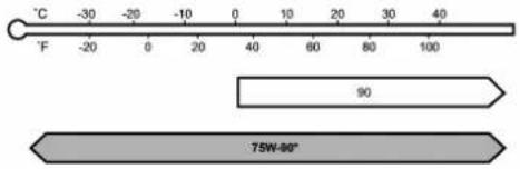 ZOM0450*:recommended ZOM0450*:recommended |
| Oilcapacity*1 | 1.4USqt(1.35liters,1.2Impqt)0.8USqt(0.8liters | 0.7Impqt) |
| Remarks*2 | “Frontdifferentialgearoil”~11-18 | “Reardifferentialgearoil”~11-18 |
*1: The indicated oil quantity is only a guideline. The necessary quantity for replacement may differ slightly depending on the temperature and other factors. After refilling the gearbox with oil, the oil level should be checked.
*2: Formoredetailsaboutmaintenanceandservice, refertotheindicatedsection.
*3: The vehicle is filled at the factory with this oil.
Fluids
| Fluid | Fluidtype*1 | Fluidcapacity*2 | Remarks*3 |
| Continuouslyvariabletransmission fluid | ConsultyourSUBARUdealer.14.7USqt(13.9liters,12.2Impqt) | “Continuouslyvariabletrans-missionfluid”-11-18 | |
| Brakefluid | FMVSSNo.116,freshDOT3orDOT4brakefluid | - | “Brakefluid”-11-19 |
*1: Useoneoftheindicatedtypesoffluid.
*2: The indicated fluid quantity is only a guideline. The necessary quantity for replacement may differ slightly depending on the temperature and other factors.
*3: Formoredetailsaboutmaintenanceandservice, refertotheindicatedsection.
Enginecoolant
| CoolantcapacityCoolanttype | |
| 8.7USqt(8.2liters,7.2Impqt) | SUBARUSuperCoolant |
The indicated coolant quantity is only a guideline. The necessary quantity for replacement may differ slightly depending on the temperature and other factors. For more details about maintenance and service, refer to "Cooling system" 11-13.
Electricalsystem
| Batterytypeandcapacity(5HR) | 12Vauxiliarybattery55D23L(12V-48AH) |
| 12VenginererastrbatteryN-55R(12V-41AH) | |
| Integratedstartergenerator12V-200A | |
| DC/DCconverter12V-130A | |
| Sparkplugs | |
Tires
| TiresizeP225/55R1795H | ||
| Wheelsize | 17 × 7J | |
| PressureFront | 32psi(220kPa,2.2kgf/cm^2) | |
| Rear | 30psi(210kPa,2.1kgf/cm^2) | |
| Wheelnuttighteningtorque | 89lbf· ft(120N· m,12kgf· m)^* | |
*: This torque is equivalent to applying approximately 88 to 110 lbf (40 to 50 kgf) at the end of the wheel nut wrench. If you have tightened the wheel nuts by yourself, havethetighteningtorquecheckedatthenearestautomotiveservicefacilityassoonaspossible.
Brakedisc
If you need information on the usage limit value of brake discs and the method for measuring them, we recommend that you consult your SUBARUdealer.
Fusesandcircuits
■Fusepanellocatedinthepassengercompartment

C00123
| Fuse panel | Fuse rating | Circuit |
| 120A | — | |
| 2Empty | ||
| 315A | ●Doorlocking | |
| 410A | ●Frontwiperdeicerrelay | |
| 510A | ●Combinationmeter●Clock | |
| 67.5A | ●Remotecontrolrear viewmirrors●Seatheaterrelay | |
| 715A | ●Combinationmeter●Integratedunit | |
| 815A | ●Stoplight | |
| 915A | ●Frontwiperdeicer | |
| 107.5A | ●Powersupply(battery) | |
| 117.5A | ●Turnsignalunit | |
| 1215A | ●Transmission control unit●Enginecontrolunit●Integratedunit | |
| 1320A | ●Accessorypoweroutlet (centerconsole)●AC110V(Ifinstalled) | |
| 1415A | ●Parkinglight●Taillight●Rearcombinationlight | |
| 1510A | ●Luggagelight●Clock | |
| 167.5A | ●Illumination | |
| 1715A | ●Seatheaters | |
| 1810A | ●Backuplight | |
| 197.5A | (Spare) | |
| 2010A | ●Accessorypoweroutlet (instrumentpanel) | |
| 217.5A | ●Starterrelay | |
| 2210A | ●Airconditioner●Rearwindowdefogger relaycoil | |
| 23Empty | ||
| 2410A | ●Audiounit●Clock | |
| 2515A | ●SRSairbagsystem | |
| 267.5A | ●Powerwindowrelay●Radiatormainfanrelay | |
| 2715A | ●Blowerfan | |
| 2815A | ●Blowerfan | |
| 2915A | ●Foglight | |
| 30Empty | ||
| 317.5A | ●Autoairconditionerunit●Integratedunit |
| Fuse panel | Fuse rating | Circuit |
| 327.5A | ●Steeringlockcontrol unit | |
| 337.5A | ●VehicleDynamicsControlunit |
■Fusepanellocatedintheenginecompartment

A) Mainfuse
| Fuse panel | Fuse rating | Circuit |
| 130A | ●ABSunit●VehicleDynamicsControlunit | |
| 225A | ●Mainfan(coolingfan) | |
| 325A | ●Subfan(coolingfan) | |
| 4 | Empty | |
| 5 | 15A | ●Brakevacuumpump system |
| 6 | 30A | ●Headlight(lowbeam) |
| 7 | 15A | ●Headlight(highbeam) |
| 820A | ●Back-up | |
| 915A | ●Horn | |
| 1025A | ●Rearwindowdefogger●Mirrorheater | |
| 1115A | ●Fuelpump | |
| 1220A | ●Continuouslyvariable transmissioncontrolunit | |
| 137.5A | ●Enginecontrolunit | |
| 1415A | ●Turnandhazardwarningflasher | |
| 1515A | ●Tail and illumination relay | |
| 167.5A | ●12V auxiliarybattery | |
| 17Empty | ||
| 18 | Empty | |
| 1915A | ●Headlight(lowbeam-righthand) | |
| 2015A | ●Headlight(lowbeam-lefthand) | |
Bulbchart
■Safetyprecautions

WARNING
- Bulbsmaybeveryhotwhile illuminated. Beforereplacing bulbs,turnoffthelightsandwait untilthebulbscooldown.Otherwise,thereisariskofsustainingaburninjury.
- FormodelswithHIDlowbeam headlights, observethefollowing precautions. Notdoingsocarries theriskofanelectricshockthat couldresultinseriousinjury because the HIDbulbsusean extremelyhighvoltage.
-Donotreplaceanyheadlight bulbs(bothlowbeamand highbeam)byyourself.
-Donotremove/restorethe headlightassembliesbyyourself.
-Donotremoveanyheadlight- assembly components by yourself.
Forreplacement,contactyour SUBARUdealer.

CAUTION
Replaceanybulbonlywithanew bulbofthespecifiedwattage. Using a bulb of different wattage could resultinafire.
Bulbchart


NOTE
LightsA,BandCaretheLED(LightEmittingDiode)type.ConsultyourSUBARUdealerforreplacement.
-CONTINUED-
WattageBulbNo.\*
1) Highbeamheadlight 12V-60WHB3
2)Lowbeamheadlight
ModelswithHIDlight12V-35WD2R
Modelswithhalogenlight12V-55WH11
3) Maplight12V-8W-
4) Domelight12V-8W-
5) Frontsidemarkerlight12V-5WW5W
6) Parkinglight12V-5WW5W
7) Frontturnsignallight
8) Frontfoglight
9) Cargoarealight
10) Tail light
11) Rear side marker light
12) Rear turn signal light
13) Back-up light
14) Licence platelight
A) Side turn signal light
B) Highmount stoplight
C) Brake light
*:ECEspecification
Vehicleidentification1) Vehicleidentificationnumber(underthe

floorcarpetoftheright-handfrontseat)
2)Emissioncontrollabel
3) Tireinflationpressurelabel
4) Certificationlabel
5) Vehicleidentificationnumberplate
6) Modelnumberlabel
7)Fuellabel
8) Airconditionerlabel
| 100 | |
| 100 | 100 |
| 100 | 100 |
| 100 | 100 |
| 100 | 100 |
| 100 | 100 |
| 100 | 100 |
| 100 | 100 |
| 100 | 100 |
| 100 | 100 |
| 100 | 100 |
| 102 | 102 |
| 102 | 102 |
| 102 | 102 |
| 102 | 102 |
| 102 | 102 |
| 102 | 102 |
| 102 | 102 |
| 104 | 104 |
| 104 | 104 |
| 104 | 104 |
| 104 | 104 |
| 104 | 104 |
| 104 | 104 |
| 106 | 106 |
| 106 | 106 |
| 106 | 106 |
| 106 | 106 |
| 106 | 106 |
| 106 | 106 |
| 108 | 108 |
| 108 | 108 |
| 108 | 108 |
| 108 | 108 |
| 108 | 108 |
| 108 | 108 |
| 112 | 112 |
| 112 | 112 |
| 112 | 112 |
| 112 | 112 |
| 112 | 112 |
| 114 | 114 |
| 114 | 114 |
| 114 | 114 |
| 114 | 114 |
| 114 | 114 |
| 99 375. | |
Consumer information and Reporting safety defects
ForU.S.A....13-2
Tireinformation....13-2
Tirelabeling....13-2
Recommended tire inflation pressure....13-4
Glossaryoftireterminology....13-5
Tirecare-maintenanceandsafety practices....13-10
Vehicleloadlimit-howtodetermine....13-10
Determining compatibility of tire and vehicle load capacities....13-13
Adversesafetyconsequencesofoverloading
onhandlingandstoppingandontires......13-14
StepsforDeterminingCorrectLoadLimit......13-14
Uniformtirequalitygradingstandards......13-15
Treadwear....13-15
TractionAA,A,B,C....13-15
TemperatureA,B,C....13-15
Reportingsafetydefects(U.S.A.) 13-16
Supplement....13-17
DeclarationofconformitywithFCCrules......13-17
ForU.S.A.
The following information has been compiled according to Code of Federal Regulations "Title49, Part 575".
Tireinformation
Tirelabeling
Manymarkings(e.g. Tiresize, Tire IdentificationNumberorTIN) are placed on the sidewalk of tire manufacturers. These markings can provide you with useful information on the tire.
▼Tiresize
Yourvehiclecomesequippedwith P-Metrictiresize.Itisimportantto understandthesizingsystemin selectingthepropertireforyour vehicles.Hereisabriefreviewof thetiresizingsystemwithabreakdownofitsindividualelements.
PMetric
WiththeP-Metricsystem, Section Widthismeasuredinmillimeters. Toconvertmillimetersintoinches, divideby25.4.TheAspectRatio (SectionHeightdividedbySection Width) helps provide dimensional information about the tire size.
Example:
| P(1) | 205/ (2) | 55/ (3) | R(4) | 16/ (5) |
(1) P=Certainiretypeusedon lightdutyvehiclessuchaspassengercars
(2) SectionWidthinmillimeters
(3) AspectRatio (= sectionheight ÷ sectionwidth).
(4) R=RadialConstruction
(5) Rimdiameterin inches
▽LoadandSpeedRatingDescriptions
Theload and speed rating descriptions will appear following the size designation.
Theyprovidetwoimportantfacts aboutthetire.First,thenumber designationisitsloadindex.Second,theletterdesignationindicates thetire'sspeedrating.
Example:
| P | 205 / 55 | R | 16 | 89 | V |
| Size designation | (6) | (7) | |||
(6)LoadIndex:Anumericalcode whichspecifiesthemaximumload atirecancarryatthespeed indicatedbyitsspeedsymbol,at maximuminflationpressure.
Forexample, "90" means 1,323 lbs (600 kg), "89" means 1,278 lbs (580 kg).

WARNING
Loadindicesapplyonlytothe tire,nottothevehicle.Putting aloadratedtireonanyvehicle doesnotmeanthevehiclecan beloadeduptothetire'srated load.
(7)SpeedRating:Analphabetic systemdescribingatire'scapability totravelatestablishedandpredeterminedspeeds. Forexample, "V"means149mph (240km/h)

WARNING
- Speedratingsapplyonlyto thetire,nottothevehicle. Puttingaspeedratedtireon anyvehicledoesnotmean thevehiclecanbeoperated atthetire'sratedspeed.
- Thespeedratingisvoidif thetiresarewornout,damaged,repaired,retreaded,orotherwisealteredfrom theiroriginalcondition.If tires are repaired,retreaded,orotherwisealtered,theymaynotbesuitablefororiginalequipment tiredesignedloadsand speeds.
▼TireIdentificationNumber(TIN)
TireIdentificationNumber(TIN)is markedontheintendedoutboard sidewall. The TIN is composed of four groups. Here is a brief review of the TIN with abreakdown of its individualelements.
| DOT | XX(1) | XX(2) | XXX(3) | XXXX(4) |
(1) Manufacturer's Identification Mark
(2)TireSize
(3)TireTypeCode
(4)DateofManufacture
The first two figures identify the week, starting with "01" to represent the first full week of the calendar year; these second two figures represent they year. Forexample, 0101 mean the 1st week of 2001.
▼Othermarkings
The followingmakings are also placedonthesidewall.
▽ Maximum permissible inflation pressure
Themaximumcoldinflationpressure to which thistiremay be inflated. For example, “300 kPa (44PSI)MAX.PRESS”
-CONTINUED-
▽Maximumloadrating
Theloadratingatthemaximum permissibleweightloadforthistire. Forexample, "MAX.LOAD580kg (1279LBS)@300kPa(44PSI) MAX.PRESS."

WARNING
Maximumloadratingapplies onlytothetire,nottothe vehicle.Puttingaloadrated tireonanyvehicledoesnot mean the vehicle can be loadeduptothetire'srated load.
▽Constructiontype
Applicableconstructionofthistire. Forexample, "TUBELESSSTEEL BELTEDRADIAL"
Construction
Thegenericnameofeachcord material usedintheplies(both sidewallandtreadarea)ofthistire. Forexample, "PLIES:TREAD2
STEEL+2POLYESTERSIDE-WALL2POLYESTER"
▽UniformTireQualityGrading (UTQG)
Fordetails, referto "Uniformtire quality grading standards" 13-15
■Recommended tireinflation pressure
▼Recommendedcoldtireinflationpressure
Forrecommendedcoldtireinflation pressureforyourvehicle'stires, referto"Tires"12-9.
▼Vehicleplacard

natural_image
Technical line drawing of a mechanical assembly with no visible text or symbolsThe vehicle placardis affixed to the driver's side B-pillar.
Example:

The vehicle placard shows original tiresize, recommended cold tire inflation pressure oneachtire at maximum loaded vehicle weight, seating capacity and loading information.
▼Adversesafetyconsequences ofunder-inflation
Drivingathighspeedswithexcessivelylowtirepressurescancause thetirestoflexseverelyandto rapidlybecomehot.Asharpin-
creaseintemperaturecouldcause treadseparation,andfailureofthe tire(s).Possibleresultinglossof vehiclecontrolcouldleadtoan accident.
▼Measuring and adjusting air pressure to achieve proper inflation
Checkand, if necessary, adjust the pressure of each tire (including the spare) at least once a month and before any long journey. Check the tire pressures when the tires are cold. Use a pressure gauge to adjust the tire pressure to the specific values. Driving even a short distance warms up the tires and increase the tire pressures. Also, the tire pressures are affected by the outside temperature. It is best to check tire pressure outdoors before driving the vehicle. When atire becomes warm, the air inside it expands, causing the tire pressure to increase. Becareful not to mistakenly release air from a warm tire to reduce its pressure.
■Glossaryoftireterminology
- Accessoryweight
The combined weight (in excess of those standard items which maybe replaced) of automatic transmission, powersteering, powerbrakes, powerwindows, powerseats, radio, and heater, to the extent that these items are available as factory-in-stalled equipment (whether installed or not).
•Bead
Thepartofthetirethatismadeof steelwires,wrappedor reinforced byplycordsandthatisshapedtofit therim.
- Beadseparation
Abreakdownofthebondbetween componentsinthebead.
•Biasplytire
Apneumatic tirein which theply cordsthatextendtothebeadsare laidatalternateanglessubstantially lessthan90degreestothecenter-lineofthetread.
•Carcass
Thetirestructure, excepttreadand
sidewallrubberwhich,whenin- flated,bearstheload.
- Chunking
The pressure in atirethathas been driven less than 1 mileor has been standing forth three hours or more.
•Cord
Thestrandsformingthepliesinthe tire.
•Cordseparation
Thepartingofcordsfromadjacent rubbercompounds.
•Cracking
Any partingwithinthe tread, sidewall, or innerlinerof thetire extendingtocordmaterial.
•Curbweight
The weight of a motor vehicle with standard equipment including the maximum capacity of fuel, oil and coolant, and if so equipped, air conditioning and additional weight optional engine.
•Extraloadtire
Atiredesignedtooperateathigher loadsandhigherinflationpressure thanthecorrespondingstandard tire.
•Groove
Thespacebetweenwoadjacent treadribs.
•Innerliner
Thelayer(s)formingtheinsidesurfaceofatubelesstirethatcontains theinflatingmediumwithinthetire.
•Innerlinerseparation
Thepartingoftheinnerlinerfrom cordmaterialinthecarcass.
•Intendedoutboardsidewall
(1) Thesidewallthatcontainsa whitewall,bearswhitelettering orbearsmanufacturer,brand, and/ormodelnamemoldingthat ishigherordeeperthanthe samemoldingontheothersidewallofthetire,or (2) Theoutwardfacingsidewall ofanasymmetricaltirethathas aparticularsidethatmustalwaysfaceoutwardwhenmount-
ingonavehicle.
•Lighttruck(LT)tire
Atiredesignatedbyitsmanufacturerasprimarilyintendedforuse onlightweight trucks ormultipurposepassengervehicles.
- Loadrating
Themaximumloadthatatireis ratedtocarryforagiveninflation pressure.
•Maximuminflationpressure
Themaximumcoldinflationpres- suretowhichatiremaybeinflated.
•Maximumloadrating
The load rating for a tire at the maximumpermissible inflation pressureforthattire.
•Maximumloadedvehicleweight
Thesumof:
(a)Curbweight
(b)Accessoryweight
(c)Vehiclecapacityweight
(d)Productionoptionsweight
•Maximumpermissibleinflation pressure
Themaximumcoldinflationpres- suretowhichatiremaybeinflated.
•Measuringrim
Therimonwhichatireisfittedfor physicaldimensionrequirements.
•Normaloccupantweight
150lbs(68kg)timesthenumberof occupantsspecifiedinthesecond columnofTable1thatisappended totheendofthissection.
•Occupantdistribution
Distributionofoccupantsinavehicleasspecifiedinthethirdcolumn ofTable1thatisappendedto the endofthissection.
- Opensplice
Anypartingatanyjunctionoftread, sidewall, or innerlinerthatextends tocordmaterial.
-Outerdiameter
Theoverall diameter of aninflated newtire.
•Overallwidth
Thelinear distancebetween the exteriorsofthesidewallsofan inflatedtire,includingelevations duetolabeling,decorations,or protectivebandsorribs.
•Passengercartire
Atireintendedforuseonpassengercars,multipurposepassenger vehicles,andtrucks,thathavea grossvehicleweighitrating(GVWR) of10,000lbs(4,535kg)orless.
•Ply
Alayerofrubber-coatedparallel cords.
•Plyseparation
Apartingofrubbercompound betweenadjacentplies.
•Pneumatictire
Amechanical device made of rubber, chemicals, fabric and steel or other materials, that, when mounted on an automotive wheel, provides the extraction and contains the gas or fluid that sustains the load.
•Productionoptionsweight
The combined weight of those installed regular production options weighing over 5.1 lbs (2.3 kg) in excess of those standard items which they replace, not previously considered incurbweight or accessoryweight, including heavy duty brakes, ride levelers, roof rack, heavy duty battery, and special trim.
•Radialplytire
Apneumatictireinwhichtheply cordsthatextendtothebeadsare laidatsubstantially90degreesto thecenterlineofthetread.
-Recommendedinflationpressure
Thecoldinflationpressurerecommendedbyvehiclemanufacturer.
•Reinforcedtire
Atiredesignedtooperateathigher loadsandathigherinflationpressuresthanthecorrespondingstandardtire.
•Rim
Ametalsupportforatireoratire andtubeassemblyuponwhichthe tirebeadsareseated.
•Rimdiameter
Nominaldiameterofthebeadseat.
•Rimsizedesignation
Rimdiameterandwidth.
•Rimtypedesignation
The industry of manufacturer's designation for arimbystyleorcode.
•Rimwidth
Nominaldistancebetweenrim flanges.
•Sectionwidth
Thelineardistancebetweenthe exteriorsofthesidewallsofan inflatedtire,excludingelevations duetolabeling,decoration,or protectivebands.
•Sidewall
That portion of atire between the tread and bead.
- Sidewallseparation
Thepartingoftherubbercompoundfromthecordmaterialin thesidewall.
•Testrim
Therimonwhichatireisfittedfor testing, anditmaybeanyrimlisted asappropriateforusewiththattire.
•Tread
That portion of atire that comes into contact with the road.
•Treadrib
Atreadsectionrunningcircumferentiallyaroundatire.
•Treadseparation
Pullingawayofthetreadfromthe tirecarcass.
•Treadwearindicators(TWI)
The projections within the principal grooves designed to give a visual indication of the degrees of wear of the thread.
•Vehiclecapacityweight
Therated cargo and luggage load plus 150 lbs (68 kg) times the vehicle's designated seating capacity.
•Vehiclemaximumloadonthe tire
Loadonanindividualtirethatis determinedbydistributingtoeach axleitsshareofthemaximum loadedvehicleweightanddividing bytwo.
•Vehiclenormalloadonthetire
Loadonanindividualtirethatis determinedbydistributingtoeach axleitsshareofthecurbweight,
accessoryweight, and normal occ- cupantweight(distributedinaccor- dance with Table 1 that isap- pended to the end of this section) and dividing by 2.
- Wheel-holdingfixture
The fixture used to hold the wheel and tire assembly securely during testing.
Table1—Occupantloadinganddistributionforvehiclenormalloadfor variousdesignatedseatingcapacities
| Designatedseating capacity,numberof occupants | Vehiclenormalload, numberofoccupants | Occupantdistributionina normallyloadedvehicle |
| 2through422infront. | ||
| 5through103 | 2infront,1insecond seat. | |
| 11through155 | 2infront,1insecond seat,1inthirdseat,1in fourthseat. | |
| 16through227 | 2infront,2insecond seat,2inthirdseat,1in fourthseat. | |
-CONTINUED-
■ Tirecare-maintenance and safetypractices
- Checkonadailybasisthatthe tiresarefreefromseriousdamage, nails,andstones.Atthesametime, checkthetiresforabnormalwear.
- Inspectthetiretreadregularly andreplacethetiresbeforetheir treadwearindicatorsbecomevisible.Whenatire'streadwear indicatorbecomesvisible,thetire iswornbeyondtheacceptablelimit andmustbereplacedimmediately. Withatireinthiscondition,driving atevenlowspeedsinwetweather cancausethevehicletohydroplane.Possibleresultinglossof vehicle control accident.
- Tomaximizethelifeofeachtire andensurethatthetireswear uniformly, it is best to rotate the tiresevery 7,500 miles(12,000 km). Forinformationaboutthetirerotation order, refer to “Tire rotation” ^2 11-27. Replaceanydamagedor unevenlyworntiresatthetimeof
rotation. After tirerotation, adjust the tire pressures and makesure the wheelnuts are correctly tightened. For information about the tightening torque and tightening sequence forthewheelnuts, refer to "incaseofaflattire" 9-4
■ Vehicleloadlimit—howto determine
The load capacity of your vehicle is determined by weight, not by available cargospace. The load limit of your vehicle is shown on the vehicle placard attached to the driver's side B-pillar. Locatethe statement "The combined weight of occupants and cargo should never exceed XXXkgorXXXlbs" on your vehicle's placard. The vehicle placard also shows seating capacity of your vehicle. Thetotalload capacity includes the total weight of driver and all passengers and their belongings, any cargo, any optionale equipments such as atralerhitch, roofrackorbike
carrier,etc.,andthetongueloadof atrailer.Thereforecargocapacity canbecalculatedbythefollowing method.
Cargocapacity=Loadlimit-(total weightofoccupants+totalweight ofoptionalequipment+tongue loadofatrailer(ifapplicable))
Forinformationaboutvehicleloading,referto"Loadingyourvehicle" 8-11.
NOTE
Yourvehicleisneitherdesigned norintendedtobeusedfor trailertowing.Therefore,never towatrailerwithyourvehicle.
▼Calculatingtotalandloadcapacitiesvaryingseatingconfigurations
Calculatetheavailableloadcapacityasshowninthefollowing examples:
Example1A

natural_image
Line drawing of a car with driver inside, showing interior seating and dashboard (no text or symbols)Vehicle capacity weight of the vehicle is 900 lbs (408 kg), which is indicated on the vehicle placard with the statement "The combined weight of occupants and cargo should never exceed 900 lbs or 408 kg".
Forexample,ifthevehiclehasone
occupantweighing154lbs(70kg) pluscargoweighing662lbs(300 kg).
- Calculatethetotalweight.
Total weight
$$ \begin{array}{l} = \frac {1 5 4 \text { lbs (70 kg) }}{(\text { Occupant })} + \frac {6 6 2 \text { lbs (300 kg) }}{(\text { Cargo })} \ = 8 1 6 \text { lbs (370 kg) } \ \end{array} $$
- Calculatetheavailableloadcapacitybysubtractingthetotal weightfromthevehiclecapacity weightof900lbs(408kg).
Available Load Capacity
$$ \begin{array}{l} = \frac {9 0 0 \text { lbs (408 kg) }}{\text {(Vehicle capacity weight)}} - \frac {8 1 6 \text { lbs (370 kg) }}{\text {(Total weight)}} \ = 8 4 \text { lbs (38 kg) } \ \end{array} $$
- Theresultofstep2showsthata further84lbs(38kg)ofcargocan becarried.
Example1B

natural_image
Line drawing of a car interior showing two drivers inside, with no text or symbols present.Forexample,ifapersonweighing 176lbs(80kg)nowentersthe samevehicle(bringingthenumber ofoccupantstotwo),thecalcula-tionsareasfollows.
- Calculatethetotalweight.
Total weight
$$ \begin{array}{l} = \frac {1 5 4 \text { lbs (70 kg) } + 1 7 6 \text { lbs (80 kg) }}{(\text { Occupant })} \ + \frac {6 6 2 \text { lbs (300 kg) }}{(\text { Cargo })} \ = 9 9 2 \text { lbs (450 kg) } \ \end{array} $$
- Calculatetheavailableloadcapacity.
Available Load Capacity
= 900 lbs (408 kg)(Vehicle capacity weight) - 992 lbs (450 kg)(Total weight)
=-92 lbs (-42 kg)
- Thetotalweightnowexceeds thecapacityweightby92lbs(42kg), sothecargoweightmustbe reducedby92lbs(42kg)ormore.
Example2A

natural_image
Line drawing of a car with driver inside and connected to a small vehicle via cable (no text or symbols)Vehicle capacity weight of the vehicle is 900 lbs (408 kg), which is indicated on the vehicle placard
withthestatement"Thecombined weightofoccupantsandcargo shouldneverexceed408kgor 900lbs".
Forexample, the vehicle has one occupant weighing 165 lbs (75 kg) plus cargoweighing 375 lbs (170 kg). In addition, the vehicle is fitted with a trailer hitch weighing 22 lbs (10 kg), to which is attached a trailer weighing 1,764 lbs (800 kg). 10% of the trailer weight is applied to the trailertongue (i.e. Tongue load = 176 lbs (80 kg)).
- Calculatethetotalweight.
Total weight
$$ \begin{array}{l} = \frac {1 6 5 \text { lbs (75 kg) }}{(\text { Occupant })} + \frac {3 7 5 \text { lbs (170 kg) }}{(\text { Cargo })} \ + \frac {2 2 \text { lbs (10 kg) }}{(\text { Trailer hitch })} + \frac {1 7 6 \text { lbs (80 kg) }}{(\text { Tongue load })} \ = 7 3 8 \text { lbs (335 kg) } \ \end{array} $$
- Calculatetheavailableloadcapacity.
Available Load Capacity
= 900 lbs (408 kg)(Vehicle capacity weight) - 738 lbs (335 kg)(Total weight)
= 162 lbs (73 kg)
- Theresultofstep2showsthata further162lbs(73kg)ofcargocan becarried.
NOTE
Yourvehicleisneitherdesigned norintendedtobeusedfor trailer towing. Therefore,never towatrailerwithyourvehicle.
Example2B

natural_image
Line drawing of a car with two people inside, connected to a small vehicle via cable (no text or symbols)Forexample,ifapersonweighing 143lbs(65kg)andachildweighing 40lbs(18kg)nowenterthesame vehicle(bringingthenumberof occupantstothree),andachild restraintsystemweighing11lbs(5 kg)isinstalledinthevehicleforthe childtouse,thecalculationsareas follows.
- Calculatethetotalweight.
Total weight
$$ = \frac {1 6 5 \text { lbs (75 kg) } + 1 4 3 \text { lbs (65 kg) }}{(\text { Occupant })} $$
$$ + \frac {4 0 \text { lbs (18 kg) }}{(\text { Occupant })} $$
$$ + \frac {1 1 \text { lbs (5 kg) }}{(\text { Child restraint })} + \frac {3 7 5 \text { lbs (170 kg) }}{(\text { Cargo })} $$
$$ + \frac {2 2 \text { lbs (10 kg) }}{\text {(Trailer hitch)}} + \frac {1 7 6 \text { lbs (80 kg) }}{\text {(Tongue load)}} $$
$$ = 9 3 2 \text { lbs (423 kg) } $$
- Calculatetheavailableloadcapacity.
Available Load Capacity
$$ = \frac {9 0 0 \text { lbs (408 kg) }}{\text {(Vehicle capacity weight)}} - \frac {9 3 2 \text { lbs (423 kg) }}{\text {(Total weight)}} $$
$$ = - 3 2 \text { lbs } (- 1 5 \text { kg }) $$
- Thetotalweightnowexceeds thecapacityweightby32lbs(15 kg), sothecargoweightmustbe reducedby32lbs(15kg)ormore.
NOTE
Yourvehicleisneitherdesigned norintendedtobeusedfor trailertowing.Therefore,never towatrailerwithyourvehicle.
■Determiningcompatibility of tire and vehicle load capacities
Thesumoffourtires' maximum loadratingsmustexceedthemax-imum loaded vehicle weight ("GVWR").Inaddition,sumofthe maximumloadratingsoftwofront tiresandoftworeartiresmust exceed each axle's maximum loadedcapacity("GAWR").Original equipmenttiresaredesignedto fulfillthoseconditions.
The maximum loaded vehicle weight is referred to Gross Vehicle Weight Rating (GVWR). And each axle's maximum loaded capacity is referred to Gross Axle Weight Rating (GAWR). The GVWR and each axle's GAWRareshown the vehicle certification label affixed to the driver's door.
-CONTINUED-
TheGVWRandfrontandrear GAWRsaredeterminedbynotonly themaximumloadratingoftiresbut alsoloadedcapacitiesofthevehicle'ssuspension,axlesandother partsofthebody.
Therefore, this means that the vehicle cannot necessarily be loaded up to the tire's maximum load rating on the tiresidewall.
■ Adversesafetyconsequencesooverloadingon handlingandstoppingand ontires
Overloadingcouldaffectvehicle handling,stoppingdistance,and vehicleandtireperformanceinthe followingways. Thiscouldleadto anaccidentandpossiblyresultin severepersonalinjury.
•Vehiclestabilitywilldeteriorate.
- Heavy and/or high-mounted loadscouldincreaseetheriskof rollover.
- Stoppingdistancewillincrease.
- Brakescouldoverheatandfail.
- Suspension, bearings, axles and other body partscould breakor experience accelerated wear that will shorten vehicle life.
•Tirescouldfail.
•Treadseparationcouldoccur.
•Tirecouldseparatefromitsrim.
■StepsforDeterminingCorrectLoadLimit
- Locatetheatement "The combined weight of occupants and cargo should never exceed XXX kgorXXXlbs." on your vehicle's placard.
- Determinethecombinedweight ofthedriverandpassengersthat willberidinginyourvehicle.
- Subtract the combined weight of the driver and passengers from XXXkgorXXXlbs.
- Theresultingfigureequalsthe availableamountofcargoand luggageeloadcapacity.Forexample, if the "XXX" amount equals 1400lbs.andtherewillbefive150 lbpassengersinyourvehicle,the
amountofavailablecargoand luggageeloadcapacityis650lbs. (1400-750(5×150)=650lbs.)
5. Determinethecombinedweight of luggage and cargobeing loaded on the vehicle. That weight may not safely exceed the available cargo and luggage load capacity calculated in Step 4.
6. If your vehicle will betowing a trailer, load from your trailer will be transferred to your vehicle. Consult this manual to determine how this reduces the available cargo and luggage load capacity of your vehicle.
NOTE
Yourvehicleisneitherdesigned norintendedtobeusedfor trailer towing. Therefore, never towatrailerwithyourvehicle.
Uniformtirequalitygrading standards
This information indicates the relative performance of passenger car tires in the area of treadwear, traction, and temperature resistance. This is a bid the consumer in making an informed choice in the purchase of tires.
Qualitygradescanbefoundwhere applicableonthetiresidewallbetweentreadshoulderandmaximumsectionwidth.Forexample:
Treadwear200TractionAATemperatureA
The quality grades apply tonew pneumatic tires for use on passen- gercars. However, they donot apply to deeptread, wintertype snowtires, space-saverortemporary uses spare tires, tires with nominal rim diameters of 12 inches or less, ortosomelimited produc-tion tires.
Allpassengercartiresmustcon-
formtoFederalSafetyRequirementsinadditiontothesegrades.
Treadwear
Thetreadweargradeisacomparativeratingbased onthe wearrateof thetirewhentestedundercontrolledconditionsonaspecified governmenttestcourse. Forexample, atiregraded150 wouldwearoneandone-half(1-1/2)timesaswellonthegovernmentcourseasatiregraded100. Therelativeperformanceoftires dependsupontheactualconditions oftheiruse, however, and may departsignificantlyfromthenorm duetovariationsindrivinghabits, servicepracticesaddifferencesin roadcharacteristicsandclimate.
■TractionAA,A,B,C
Thetractiongrades, from highest to lowest, are AA, A, Band C. Those grades represent the tire's ability to stop on wet pavement as measured under controlled conditions spe-
cifiedgovernmenttestsurfacesof asphaltandconcrete.Atiremarked C mayhave poor tractionperformance.

WARNING
Thetractiongradeassignedto thistireisbasedonstraight-aheadbrakingtractiontests, anddoesnotincludeacceleration,cornering,hydroplan-ing, orpeaktraction characteristics.
■TemperatureA,B,C
ThetemperaturegradesareA(the highest),B,andC,representingthe tire'sresistancetothegenerationof heatanditsabilitytodissipateheat whentestedundercontrolledconditionsonaspecifiedindoorlaboratorytestwheel.Sustainedhigh temperaturecancausethematerial ofthetireto degenerateandreduce tirelife,andexcessivetemperature canleadtosuddentirefailure.The
-CONTINUED-
gradeCcorrespondstoalevelof performancewhichallpassenger cartiresmustmeetunderthe FederalMotorVehicleSafetyStandardsNo.109.GradesBandA representhigherlevelsofperformanceonthelaboratorytestwheel thantheminimumrequiredbylaw.

WARNING
Thetemperaturegradeforth this tireisestablishedforatire thatisproperlyinflatedand notoverloaded. Excessive speed,underinflation,orexcessiveloading,eitherseparatelyorincombination,can causeheatbuildupandpossibletirefailure.
Reportingsafetydefects (U.S.A.)
If you believethat your vehicle has a defect which could cause a crash or could cause injury or death, you should immediately inform the National Highway Traffic Safety Administration (NHTSA) in addition to notifying Subaru of America, Inc.
IfNHTSAreceivessimilarcomplaints,itmayopenaninvestigation,andifitfindsthatasafety defectexistsinagroupofvehicles,itmayorderarecalland remedy campaign. However, NHTSAcannotbecomeinvolved inindividualproblemsbetween you,yourdealer,orSubaruof America,Inc.TocontactNHTSA, youmaycalltheVehicleSafety Hotlinetoll-freeat1-888-327-4236 (TTY:1-800-424-9153); goto http://www.safercar.gov;orwrite to:Administrator,NHTSA,1200
NewJerseyAvenue, SE, West Building, Washington, DC20590. You can also obtain other information about motor vehicles safety from http://www.safercar.gov.
Supplement
■ DeclarationofconformitywithFCCrules
▼Electrostaticsensorforoccupantdetectionsystem
DECLARATION OF CONFORMITY WITH FCC RULES
According to 47CFR, Part 18
We, DENSO INTERNATIONAL AMERICA, INC.
: 24777 Denso Drive, Southfield, Michigan
Declare that the product:
Trade Name: DENSO
Kind of equipment: Electrostatic sensor Model Name: DECS001
Complies with 47CFR Part 18 of the FCC rules.
Party Responsible: KATSUHIKO AKAMATSU

D00208
| 100 | |
| 100 | 100 |
| 100 | 100 |
| 100 | 100 |
| 100 | 100 |
| 100 | 100 |
| 100 | 100 |
| 100 | 100 |
| 100 | 100 |
| 100 | 100 |
| 100 | 100 |
| 102 | 102 |
| 102 | 102 |
| 102 | 102 |
| 102 | 102 |
| 102 | 102 |
| 102 | 102 |
| 102 | 102 |
| 104 | 104 |
| 104 | 104 |
| 104 | 104 |
| 104 | 104 |
| 104 | 104 |
| 104 | 104 |
| 106 | 106 |
| 106 | 106 |
| 106 | 106 |
| 106 | 106 |
| 106 | 106 |
| 106 | 106 |
| 108 | 108 |
| 108 | 108 |
| 108 | 108 |
| 108 | 108 |
| 108 | 108 |
| 108 | 108 |
| 112 | 112 |
| 112 | 112 |
| 112 | 112 |
| 112 | 112 |
| 112 | 112 |
| 114 | 114 |
| 114 | 114 |
| 114 | 114 |
| 114 | 114 |
| 114 | 114 |
| 99 375. | |
Index
14-2Index
A
Abbreviation....3
ABS(Anti-lockBrakeSystem)....7-22
Warninglight....3-20
Accesskey 2-9
Warninglight....3-25
Accessories....5-3,11-40
Accessorypoweroutlet....6-7
Aircleanerelement....11-15
Airconditioner
Automaticclimatecontrol....4-5
Manualclimatecontrol....4-6
Airfiltrationsystem....4-10
Airflowmode....4-6
Alarmsystem....2-25
All-WheelDrivewarninglight....3-22
Aluminumwheel....11-31
Cleaning....10-3
Antennasystem....5-2
Anti-lockBrakeSystem(ABS)....7-22
Armingthesystem....2-26
Armrest....1-8
Ashtray....6-9
ATOILTEMPwarninglight....3-18
Audio
Antennasystem....5-2
Set....5-3
Autoon/offheadlights....3-79
Auto-dimmingmirror/compass....3-89,3-90
Automaticheadlightbeamleveler....3-84
Warninglight....3-30
AutomaticLockingRetractor/EmergencyLocking Retractor(ALR/ELR)....1-12
B
Battery
Drainagepreventionfunction....2-7
Jumpstarting....9-14
Replacement(accesskey)....11-46
Replacement(remoteenginestarttransmitter)......7-14
Replacement(transmitter)....11-47
Vehiclebattery....11-37
Boosterseat....1-31
Bottleholder....6-7
Brake
Assist....7-21
Booster....7-21,11-20
Disc....12-9
Fluid....11-19,12-8
Padandlining....11-21
Parking....7-28,11-22
Pedal....11-20
System....7-21
Brakesystem....7-21
Warninglight....3-21
Braking....7-21
Tips....7-21
Breaking-inofnewbrakepadsandlinings....11-21
Bulb
Chart....12-14
Replacing....11-40
Index14-3
C
Cargoarea Cover....6-11 Light....6-2, 11-45 Tie-downhooks....6-13 Catalyticconverter....8-3
Center Console....6-5
Changing Coolant....11-15 Oilandoilfilter....11-11
Chargewarninglight....3-17
CHECKENGINEwarninglight/Malfunctionindicator light....3-15
Checking Brakepedalfreeplay....11-20 Brakepedalreservedistance....11-20 Coolantlevel....11-14 Fluidlevel(brakefluid)....11-19 Fluidlevel(washerfluid)....11-31 Oillevel(engineoil)....11-10
Childrestraintsystems....1-24 Installationofaboosterseat....1-31 InstallationwithALR/ELRseatbelt....1-27 Lowerandtetheranchorages....1-32 Toptetheranchorages....1-36
Childsafety....4 Locks....2-32
Chime Key....3-5 Light....3-79
Seatbelt....3-13
Cigarettelighter....6-8
Cleaning Aluminumwheels....10-3 Interior....10-5 Ventilationgrille....4-9
Climatecontrolsystem....4-3 Automatic....4-5 Manual....4-6
Clock 3-42
Coathook....6-10
Compass....3-89,3-90
Console....6-5
Continuouslyvariabletransmission Oiltemperaturewarninglight(ATOILTEMP)....3-18 Continuouslyvariabletransmission(CVT)....7-14 Fluid....11-18,12-8
Coolant....11-14,12-8 Temperaturehighwarninglight....3-16 Temperaturelowindicatorlight....3-16
Coolingsystem....11-13
Corrosionprotection....10-4
Cruisecontrol....7-33 Indicatorlight....3-30 Setindicatorlight....3-30
Cupholder....6-6
D
Daytimerunninglightsystem....3-82 Defogger....3-96 Defrosting....4-9
14-4Index
Deicer....3-96
Differentialgearoil Front.....11-18,12-7 Rear.....11-18,12-7
Dimensions....12-2
Disarmingthealarmsystem....2-29
Discbrakepadwearwarningindicators....7-22
Domelight....6-2,11-45
Door Locks....2-5 Openwarninglight....3-22
Drivebelts....11-17
Driving AWDvehicles....8-4 Carphone/cellphone....7
Drinking....6
Drugs....6
Foreigncountries....8-4
Offroad....8-6
Pets....7 Snowyandicyroads....8-9
Tips....7-19,8-2,8-4
Tiredorsleepy....6
Winter....8-7
E ECOgauge....3-12
Electricalsystem....12-8
ElectronicBrakeForceDistribution(EBD)system....7-23 Warning....3-21
EmergencyLockingRetractor(ELR)....1-12
Engine Compartmentoverview....11-9 Coolant....11-14,12-8 Exhaustgas(carbonmonoxide)....5,8-2 Hood....11-7 Lowoillevelwarninglight....3-18 Oil....11-10,12-5 Overheating....9-17
EV(ElectricVehicle)modelamp....3-31 Eventdatarecorder....8 Exteriorcare....10-2
F Floormat....6-10 Fluidlevel Brake....11-19 Continuouslyvariabletransmission....11-18
Foglight Bulb....11-42,12-14 Indicatorlight....3-30 Switch....3-84
Front Differentialgearoil....11-18, 12-7 Seatbeltpretensioners....1-20 Turnsignallight....11-42
Frontseats....1-2 Forwardandbackwardadjustment....1-3 Headrestraintadjustment....1-5 Reclining....1-4 Seatcushionheightadjustment....1-4
Fuel 7-2
Consumptionscreen....3-38
Economyhints....8-2
Fillerlidandcap....7-3
Gauge....3-11
Requirements....7-2,12-4
Fuses....11-38
Fusesandcircuits....12-10
G
GAWR(GrossAxleWeightRating)....8-13
Glovebox....6-5
GVWR(GrossVehicleWeightRating)......8-13
H
Hazardwarningflasher....3-7,9-2
Headrestraintadjustment
Frontseat....1-5
Rearseat....1-8
Headlight
Beamleveler....3-84
Bulbreplacing....11-40
Bulbwattage....12-14
Control switch.... 3-79
Flasher....3-81
Indicatorlight....3-30
Welcome lighting function 3-80
HIDheadlights....1,11-40
Highbeamindicatorlight....3-30
High/lowbeamchange(dimmer).... 3-81
Hillstartassist....7-30,11-21
OFFindicatorlight....3-22
Warninglight....3-22
HomeLink ^ ......3-90
Hook
Cargotie-down....6-13
Coat....6-10
Shoppingbag....6-11
Towingandtie-down....9-18
Horn....3-98
Hose and connections.... 11-14
HybridREADYIndicatorLight....3-31
Hybridsystem
Faillamp....3-31
Features....9
Startingandstopping....7-8
|
Ignitionswitch....3-3
Light....3-5
Illuminationbrightnesscontrol....3-83
Immobilizer....2-3
Indicatorlight(securityindicatorlight)....3-29
Indicatorlight
Coolanttemperaturelow....3-16
Cruisecontrol....3-30
Cruisecontrolset....3-30
EV(ElectricVehicle)mode....3-31
Frontfoglight....3-30
Headlight....3-30
Highbeam....3-30
HillstartassistOFF....3-22
HybridREADY....3-31
14-6Index
Immobilizer....3-29
Security....3-29
Selectlever/Gearposition....3-30
Turnsignal....3-30
VehicleDynamicsControlOFF....3-24
VehicleDynamicsControloperation....3-23
Insidemirror....3-88,3-90
Interiorlights....6-2
J
Jumpstarting....9-14
K
Key....2-3
Number....2-3
Reminderchime....3-5
Replacement....2-4
Keylessaccessentryfunction....2-13
Keylessaccesswithpush-buttonstartsystem....2-9
Disablingkeylessaccessfunctions....2-17
Lockingandunlockingdoors....2-13
Openingreargate....2-15
Warningchimesandwarninglight....3-25
Whenaccesskeydoesnotoperateproperly....9-23
Keylessentrysystem....2-21
L
Lapbeltpretensioner....1-22
Leatherseatmaterials....10-5
Licenseplatelight....11-44
Light
Backup....11-42
Cargoarea....6-2,11-45
Controlswitch....3-79
Daytimerunning....3-82
Dome....6-2,11-45
Frontfog....3-84,11-42
Frontsidemarker....3-79,12-14
Ignitionswitch....3-5
Licenseplate....11-44
Map....6-3,11-44
Parking....11-42
Rearcombination....11-42
Rearsidemarkerlight....11-42
Stop....11-42
Tail....11-42
Turnsignal....3-82,11-42
Loadingyourvehicle....8-11
Lowfuelwarninglight....3-22
Lowtirepressurewarninglight....3-18
Lowerandtetheranchorage....1-32
M
Maintenance
Precautions....11-3
Schedule....11-3
Seatbelt....1-20
Tips....11-5
Tools....9-2
Malfunctionindicatorlight(checkenginewarninglight)....3-15
Manual
Mode(continuouslyvariabletransmission)....7-17
Maplight....6-3,11-44
Metersandgauges....3-8
Mirrordefogger....3-96
Mirrors....3-88
Moonroof....2-37
Multifunctiondisplay....3-32
N
Newvehiclebreak-indriving....8-2
0
Odometer....3-10
Offroaddriving....8-6
Oilfilter....11-11
Oillevel
Engine....11-10
Warninglight....3-18
Oilpressurewarninglight....3-17
Outside
Mirrordefogger....3-96
Mirrors....3-96
Temperatureindicator....3-36
Overheatingengine....9-17
P
Parking
Brake....7-28
Brakestroke....11-22
Light....11-42
Tips....7-29
Pedestrianalertwarninglight....3-31
Periodicinspections....8-4
Petrolfuel....7-2
PINCodeAccess....2-20
Power
Door locking switch.... 2-8
Outlets 6-7
Outsidemirrors....3-96
Steering....7-20
Steeringwarninglight....3-22
Windows....2-32
Precautionsagainstvehiclemodification....1-24, 1-65
Combinationlights....11-42
Differential gear oil.... 11-18, 12-7
Gate....2-36,9-22
Turnsignallight....11-42
Rearseat....1-7
Armrest....1-8
Foldingdown....1-10
Headrestraintadjustment....1-8
Rearviewcamera....6-14
Rearwindow
Defogger....3-96
Wiperandwasherswitch....3-87
Wiperblades....11-35
Recommended Brakefluid....12-8
Continuouslyvariabletransmissionfluid....12-8
Engineoil....12-5
Frontdifferentialgearoil....12-7
Reardifferentialgearoil....12-7
Sparkplugs....12-8
Refueling....7-4
Remoteenginestartsystem....7-12
Remotekeylessentrysystem....2-21
Replacement Brakepadandlining....11-21 Wiperblades....11-33
Replacing Accesskeybattery....11-46
Aircleanerelement....11-16
Losttransmitters(remotekeylessentrysystem)......2-24
Remoteenginestarttransmitterbattery....7-14
Remotekeylessentrytransmitterbattery....11-47
Replacingbulbs....11-40,12-14
Backuplight....11-42
Cargoarealight....11-45
Domelight....11-45
Frontfoglight....11-42
Frontturnsignallight....11-42
Headlight....11-40
Licenseplatelight....11-44
Maplight....11-44
Parkinglight....11-42
Rearcombinationlight....11-42
Rearsidemarkerlight....11-42
Rearturnsignallight....11-42
Stoplight....11-42
Taillight....11-42
Rockingthevehicle....8-11
Roofrails....8-13
S
Safety Precautionswhendriving....4 Symbol.... Warnings....
Seat Fabric....10-5 Front....1-2 Heater....1-6 Rear....1-7
Seatbelt....4,1-11 Fastening....1-13 Maintenance....1-20 Pretensioners....1-20 Safetytips....1-11 Warninglightandchime....3-13
Security Alarmsystem....2-25 Immobilizer....2-3 Indicatorlight....3-29 Shocksensors....2-31
Selectlever Positionindicator....3-30 Shiftlockfunction....7-18
Shocksensors....2-31
Shoppingbaghook....6-11
Shoulderpretensioners....1-20
Snowtires....8-10,11-23
Snowyandicyroads....8-9
Soundingapanicalarm....2-23
Sparkplugs....11-17,12-8
Specifications....12-2
Speedometer....3-10
SRS
Curtainairbag....1-56
Frontalairbag....1-46
Sideairbag....1-56
SRSairbag(SupplementalRestraintSystemairbag)...4,1-37
SRSairbagsystem
Monitors....1-63
Servicing....1-64
Warninglight....3-15
Stateemissiontesting(U.S.only)....7-6
Steeringwheel
Power....7-20
Tilt/telescopic....3-98
Stoplight....11-42
Storagecompartment....6-5
Sunshade....2-39
Sunvisors....6-4
SupplementalRestraintSystemairbag(SRS)....1-37
Syntheticleatherupholstery....10-5
T
Tachometer....3-11
Temperaturewarninglight
ATOILTEMP....3-18
Coolant....3-16
Tether(childrestraintsystem)....1-32, 1-36
Tie-downhooks....9-18
Tire 11-22,12-9
Chains....8-11
Inspection....11-24
Pressuresandwear....11-24
Replacement....11-28
Rotation....11-2
Sizeandpressure....12-9
Types....11-22
Tirepressuremonitoringsystem(TPMS)....7-27,11-23
Warninglight....3-18
Tiresandwheels....11-22
Tools....9-2
Toptetheranchorages....1-32,1-36
Towing....9-18
Allwheelsontheground....9-21
Flat-bedtruck....9-20
Hooks....9-18
Trailer
Towing....8-14
Tripmeter....3-10
Turnsignal
Indicatorlights....3-30
Lever 3-82
14-10Index
V
Valetmode....2-30
Vanitymirror....6-4
Vehicle
Capacityweight....8-12
Identification....12-17
Symbols....3
VehicleDynamicsControl
OFFindicatorlight....3-24
OFFswitch....7-26
Operationindicatorlight....3-23
System....7-24
Warninglight....3-23
Ventilator....4-2
W
Warningandindicatorlights....3-12
Warningchimes
Keylessaccesswithpush-buttonstartsystem....3-25
Seatbelt 3-13
Warninglight
ABS 3-20
Accesskey....3-25
All-WheelDrive....3-22
ATOILTEMP....3-18
Automaticheadlightbeamleveler....3-30
Brakesystem....3-21
Charge....3-17
CHECKENGINE 3-15
Coolanttemperaturehigh....3-16
Dooropen....3-22
Enginelowoillevel....3-18
Hillstartassist....3-22
Hybridfaillamp....3-31
Keylessaccesswithpush-buttonstartsystem....3-25
Lowfuel....3-22
Lowtirepressure....3-18
Oilpressure....3-17
Pedestrianalert....3-31
Powersteering....3-22
Seatbelt 3-13
SRSairbagsystem....3-15
VehicleDynamicsControl....3-23
Windshieldwasherfluid....3-18
Warranties....1
Washing....10-2
Waxingandpolishing....10-3
Wearindicators....11-27
Welcomelightingfunction....3-80
Wheel
Aluminum....11-31
Balance....11-26
Nuttighteningtorque....12-9
Replacement....11-30
Windows....2-32
Windshield
Washerfluid....11-31
Wiperandwasherswitches....3-86
Wiperblades....11-33
Wiperdeicer....3-96
Winter
Driving....8-7
Index14-11
Tires....8-10,11-23 Wiperandwasher....3-85 Wiperdeicer....3-96
| 100 | |
| 100 | 100 |
| 100 | 100 |
| 100 | 100 |
| 100 | 100 |
| 100 | 100 |
| 100 | 100 |
| 100 | 100 |
| 100 | 100 |
| 100 | 100 |
| 100 | 100 |
| 102 | 102 |
| 102 | 102 |
| 102 | 102 |
| 102 | 102 |
| 102 | 102 |
| 102 | 102 |
| 102 | 102 |
| 104 | 104 |
| 104 | 104 |
| 104 | 104 |
| 104 | 104 |
| 104 | 104 |
| 104 | 104 |
| 106 | 106 |
| 106 | 106 |
| 106 | 106 |
| 106 | 106 |
| 106 | 106 |
| 106 | 106 |
| 108 | 108 |
| 108 | 108 |
| 108 | 108 |
| 108 | 108 |
| 108 | 108 |
| 108 | 108 |
| 112 | 112 |
| 112 | 112 |
| 112 | 112 |
| 112 | 112 |
| 112 | 112 |
| 114 | 114 |
| 114 | 114 |
| 114 | 114 |
| 114 | 114 |
| 114 | 114 |
| 99 375. | |
GASSTATIONREFERENCE
Fuel:
Useonlyunleadedgasolinewithanoctaneratingof87AKI (90RON)orhigher.
■Fueloctanerating:
This octanerating is the average of the Research Octane and Motor Octan numbers and is commonly referred to as the Anti Knock Index (AKI). Refer to “Fuel octane rating” or 7-2.
Fuelcapacity:
13.7USgal(52liters, 11.4Impgal)
Engineoil:
Useonlythefollowingoils.
- APIclassificationSMwiththewords"ENERGYCONSERVING" or SN with the words "RESOURCE CONSERVING"
●orILSACGF-4orGF-5, which can be identified with the ILSAC certification mark (Starburstmark)
For the complete viscosity requirements, refer to "Engine oil" 12-5.
■Engineoilcapacity:
5.1USqt(4.8liters,4.2Impqt)
The indicated oil quantity is only a guideline and is estimated based on a case when the engine oil is changed with an oil filter. After refilling the engine with oil, the oil level should be checked using the oil level gauge. Formed details about maintenance and service, refer to "Engine oil" 11-10.
Coldtirepressure:
Referto"Tires" 12-9.


- Warranties
- ■WarrantiesforU.S.A.
- WarrantiesforCanada
- ■ModelswithHIDheadlights
- CAUTION
- ■ ModelswithoutHIDheadlights
- NOTE
- HowtousethisOwner's Manual
- ■UsingyourOwner'sManual
- Chapter1: Seat, seatbelt and SRS airbags
- Chapter2:Keysanddoors
- Chapter3: Instrumentsandcontrols
- Chapter4:Climatecontrol
- Chapter5:Audio
- Chapter6: Interiorequipment
- Chapter7: Starting and operating
- Chapter8:Drivingtips
- Chapter9: Incaseofemergency
- Chapter10: Appearancecare
- Chapter11: Maintenance and service
- Chapter12:Specifications
- Chapter13: Consumerinformation and Reportingsafetydefects
- Chapter14:Index
- ■ Safetywarnings
- WARNING
- Abbreviationlist
- Vehicle symbols
- Safetyprecautionswhen driving
- ■ SeatbeltandSRSairbag
- Childsafety
- ■Engineexhaustgas(carbon monoxide)
- ■ Drinkinganddriving
- Drugsanddriving
- ■ Drivingwhentiredorsleepy
- ■ Modificationofyourvehicle
- ■ Carphone/cellphone and driving
- ■ Drivingvehiclesequipped withnavigationsystem
- ■Drivingwithpets
- Tirepressures
- Generalinformation
- ■ Californiaproposition65 warning
- ■ CaliforniaPerchlorateAdvisory
- ■ Noisefromunderthevehicle NOTE
- ■ Eventdatarecorder
- Hybridsystemfeatures
- ■ Generalinformationforstopping/restartingoftheengine andelectricmotor
- Whenstarting:
- Whenacceleratinggraduallyordriving ataconstantspeed:
- Whenacceleratingsharply:
- Whendrivingusingelectricmotor poweraloneandthenaccelerating:
- Whenbraking:
- Whenthevehiclehasbeenstopped:
- Components
- ■Safetyprecautions
- ■Generalinformation
- ▼Tipsforhighvoltagebattery
- ▼Regardingsoundsandvibrations particulartothehybridsystem
- electricmotorpower
- ▼PedestrianAlertsystem
- ▼Regardingelectromagneticwaves
- ▼Screendisplay
- Illustratedindex
- Interior
- Lightcontrolandwipercontrollevers/switches
- ■ Combinationmeter
- Functionsettings
- Seat, seatbelt and SRS airbags
- Frontseats
- ■Headrestraintadjustment
- Toraise:
- Tolower:
- Toremove:
- Toinstall:
- Totilt:
- Toreturn:
- Seatheater(ifequipped)
- ■ Safetyprecautions
- ▼Rearcenterseatingposition
- ■ Foldingdowntherearseat-back
- Seatbelts
- ■Seatbeltsafetytips
- ▼Infantsorsmallchildren
- Children
- EmergencyLockingRetractor(ELR)
- ■AutomaticLockingRetractor/EmergencyLockingRetractor(ALR/ELR)
- ■ Seatbeltwarninglight andchime
- ■ Fasteningtheseatbelt
- ▼Frontseatbelts
- ▼Rearseatbelts(exceptrearcenter seatbelt)
- ■ Seatbeltmaintenance
- Frontseatbeltpretensioners
- ■ Seatbeltwithshoulderbelt pretensioner
- ■ Seatbeltwithshoulderbelt andlapbeltpretensioners
- senger\*
- Systemmonitors
- ■Systemservicing
- thevehicle
- ■Precautionsagainstvehicle modification
- Childrestraintsystems
- ■Wheretoplaceachildre- straintsystem
- A:Frontpassenger'sseat
- B: Rearseat, window-sideseating positions
- C: Rearseat, centerseating position
- ■Installingchild restraint systems with ALR/ELR seatbelt
- ■Installingaboosterseat
- ■ Installationofchildrestraint systemsbyuseoflowerand tetheranchorages(LATCH)
- ▼Toinstallachildrestraintsystem usinglowerandtetheran-chorages
- ■ Toptetheranchorages
- ▼Tohookthetoptether
- \*SRSairbag(Supplemental RestraintSystemairbag)
- ■ General precautions regarding SRSairbagsystem
- seatfacingthesidewindow
- getfreshairpromptly.
- ■ SUBARUadvancedfrontal airbagsystem
- ▼Driver'sSRSfrontalairbag
- ▼Frontpassenger'sSRSfrontalair-bag
- ▼Passenger'sfrontalairbagONand OFFindicators
- ▼Occupantdetectionsystem
- SRSairbagsystemwarninglight
- ▼Conditionsinwhichfrontpassenger'sSRSfrontalairbagisactivated
- Howtocontactthevehiclemanufacturerconcerningmodifications forpersonswithdisabilitiesthat mayaffecttheadvancedairbag system
- ▼Operation
- ■ SRSsideairbagandSRS curtainairbag
- ExamplesofthetypesofaccidentsinwhichtheSRScurtainairbagwillmost likelydeploy.
- ExamplesofthetypesofaccidentsinwhichtheSRSsideairbagisunlikely todeploy.
- ■ SRSairbagsystemservicing
- Precautionsagainstvehicle modification
- Keys and doors
- Keysanddoors
- Keys
- Keytypes
- ■Keynumberplate
- Immobilizer
- Formodelswith "keylessaccesswith push-buttonstartsystem":
- Formodelwithout"keylessaccess withpush-buttonstartsystem":
- ■ Securityindicatorlight
- ■Keyreplacement
- ■ Certificationforimmobilizer system
- ▼Modelswith"keylessaccesswith push-buttonstartsystem"
- FCCWARNING
- REMARQUE
- ■Batterydrainageprevention function
- ■Keylock-inpreventionfunction
- ▼Behaviorwithkeylock-inpreventionfunctionoperational
- ▼Behaviorwithkeylock-inpreventionfunctionnon-operational
- Keylessaccesswithpush-buttonstartsystem(if equipped)
- ▽Operatingrangetips
- ▼Howtousekeylessaccessfunctions
- ▼Keylessaccessfunctiontips
- ▼Powersavingfunction
- ▽Recoveryfrompowersaving mode
- Case1:
- Case2:
- ▼Doorunlockselectionfunction
- ■ Selectingaudiblesignaloperation
- ■Warningchimesandwarning light
- ■Disablingkeylessaccess function
- ▼Disablingfunctions
- ∇Byoperatingthedriver'sdoor
- ▼Enablingfunctions
- ■Whenaccesskeydoesnot operateproperly
- ■Replacingbatteryofaccess key
- ■Replacingaccesskey
- ■ Certificationforkeylessaccesswithpush-buttonstart system
- ▼Canada-spec.models
- PINCodeAccess(models with "keylessaccesswith push-buttonstartsystem")
- RegisteringaPINcode
- ▼Preparation
- ▼Registration
- ■ Unlocking
- Remotekeylessentrysystem
- ■Lockingthedoors
- ■ Unlockingthedoors
- ■ Unlockingthereargate
- ■Vehiclefinderfunction
- ■Soundingapanicalarm
- ■Selectingaudiblesignaloperation(modelswithout "keylessaccesswithpush-buttonstartsystem")
- ■Replacingthebattery
- ■Replacinglosttransmitters
- ■ Certificationforremotekey-lessentrysystem
- Formodelswithout"keylessaccess withpush-buttonstartsystem":
- Systemoperation
- ■Activatinganddeactivating thealarmsystem
- If the system was previously activated:
- ■ If you have accidentally triggered the alarmsystem
- ▼Tostopthealarm
- Armingthesystem
- ▼Tips
- ▼Toarmthesystemusingtheaccess key/remotetransmitter
- Accesskey
- Transmitter
- Securityindicatorlight
- ▼Toarmthesystemusingpower doorlockingswitches
- ▼Toarmthesystemusingthekey-lessaccessfunction(ifequipped)
- ■ Disarmingthesystem
- ▼Emergencydisarming
- ■ Valetmode
- ■Passivearming
- ▼Passivearmingmode
- ▼Toenterthepassivemode
- ▼Armingthesystem
- ▼Disarmingthesystem
- ■ Trippedsensoridentification
- ■Shocksensors(dealeroption)
- Examples:
- Childsafetylocks
- Windows
- ■ Powerwindowoperationby driver
- ▼Driver'ssidepowerwindow switches
- ▼Operatingthedriver'swindow
- Toopen:
- Toclose:
- ▼Anti-entrapmentfunction
- Tolock:
- Tounlock:
- ■ Powerwindowoperationby passengers
- ▼Passenger'ssidepowerwindow switches
- ▼Operatingthewindows
- ■ Initializationofpowerwindow
- Reargate
- Lock/unlock
- Moonroof(ifequipped)
- ■ Moonroofswitches
- Instruments and controls
- Instrumentsandcontrols
- Ignitionswitch
- ■ Modelswithpush-button startsystem
- ■ LOCK(off)
- ACC
- ON
- START
- ■Keyreminderchime
- ■ Ignitionswitchlight(if equipped)
- Push-buttonignitionswitch (modelswithpush-button startsystem)
- ■ Operatingrangeforpush-buttonstartsystem
- ▼Batterydrainagepreventionfunction
- Metersandgauges
- ■ Combinationmeterillumination
- ■ Canceling the function for meter/gaugeneedlemovementuponturning on the ignitionswitch
- ■ Meter/Gaugeneedleilluminationsetting
- Activated:
- Deactivated:
- Tochangethesetting:
- ■Speedometer
- Tachometer
- Fuelgauge
- Warningandindicatorlights
- ■ Initialilluminationforsystem check
- ■ SRSairbagsystem warninglight
- ■Frontpassenger'sfrontal airbagONandOFFindicators
- ■ CHECKENGINE warninglight/Malfunctionindicatorlight
- ▼Ifthelightilluminatessteadily
- ▼Ifthelightisblinking
- ■Chargewarninglight
- Oilpressurewarning light
- Enginelowoillevel warninglight
- Windshieldwasher fluidwarninglight
- ATOILTEMPwarning light
- ▼Transmissioncontrolsystemwarning
- Lowtirepressure warninglight(U.S.-spec. models)
- ABSwarninglight
- yourSUBARUdealer.
- ■ Brakesystem warninglight(red)
- ▼Parkingbrakewarning
- ▼Brakefluidlevelwarning
- ▼ElectronicBrakeForceDistribution (EBD)systemwarning
- ▼Vacuumpumpfaillamp
- ■ Lowfuelwarninglight
- ■ Hillstartassistwarning light/Hillstartassist OFFindicatorlight
- ▼Hillstartassistwarninglight
- ▼HillstartassistOFFindicatorlight
- ■ Dooropenwarning light
- ■ All-WheelDrivewarninglight
- AWD
- ■ Powersteeringwarninglight
- ▼VehicleDynamicsControloperationindicatorlight
- ■ VehicleDynamics ControlOFFindicator light
- ■Warningchimesandwarning lightofthekeylessaccess withpush-buttonstartsystem(ifequipped)
- ▼Listofwarnings
- ▼Alarmsystem
- ▼Immobilizersystem
- Formodelswith"keylessaccesswith push-buttonstartsystem":
- ■Turnsignalindicator lights
- ■ Highbeamindicator light
- Cruisecontrolindica- torlight
- Cruisecontrolsetindicatorlight
- ■ Automaticheadlight beamlevelerwarning light(modelswithHID headlights)
- ■ Frontfoglightindicator light(ifequipped)
- ■ Headlightindicator light(ifequipped)
- HybridFailLamp
- ■ Pedestrianalertwarninglight
- ■ HybridREADYIndicatorLight
- ■ EV(ElectricVehicle) modelamp
- ▼Activation/deactivationsettings
- Multifunctiondisplay
- Features
- ■ Welcomescreen
- Date screen
- ■ Ending screen
- ■ Self-check screen
- Exampleofnotification
- followingconditions.
- Warninginformation(displayexample)
- ■Basicscreens
- ▼Basicscreenitems
- ▼Outsidetemperatureindicator
- Icyroadsurfacewarningscreen
- Informationreminder
- ▽Topdisplay
- ▽Clock
- ▼Energyflowscreen
- Triplemeterscreen(displayexample)
- Calendar
- Selectionscreen
- Dateandtimesettings
- ▼Preparationfordatesetting
- ▼Currentdateandtimesetting
- ▼Birthdaysetting
- bedeactivated.
- ▼Anniversarysetting
- ▼Clearingbirthdayoranniversary
- ▼Daylightsavingtimesetting
- ■ Imagequalityandvolume settings
- ▼Preparationforimagequalityand volumesettings
- ▼Contrastsetting
- ScreenOFFsetting
- Restoringthescreen
- ▼Beepvolumesetting
- ■ Screensettings
- ▼Preparationforscreensettings
- ▼Topdisplaysetting
- ▼Fuelconsumptionscreensetting
- ▼Economyhistorysetting
- ▼Triplemetersetting
- ▼Clock/calendarscreensetting
- ▼Bypasssscreensetting
- ▼Languagesetting
- ■ Maintenancesettings
- ▼Preparationformaintenancesettings
- ▼Engineoilsetting
- ▼ Oilfiltersetting
- ▼ Tiresetting
- ▼ Maintenanceschedulesetting
- ▼ On/Offsetting
- ▼Clearsetting
- ■ Drivinghistoryregistration
- Carsettings
- ▼Preparationforcarsettings
- ▼Keylessbuzzervolumesetting
- ▼Audiblesignalsetting
- ▼Hazardwarningflashersetting
- ▼Defoggersetting
- ▼Interiorlightoffdelaytimersetting
- ▼Autolightsensorsensitivitysetting
- ▼Keylessaccesssetting(models with "keylessaccesswithpush-buttonstartsystem")
- Preparationforkeylessaccess settings
- Driver'sdoorunlocksetting
- ▽Reargateunlocksetting
- ■ Initialize
- ▼Preparationforinitialization
- ▼ Resettofactorydefaultsettings
- ▼Lifetimefuelconsumptionresetting
- Lightcontrolswitch
- ■Precautionsandtips
- "D"position
- "EDGE"position
- ▼Welcomelightingfunction
- Whenapproaching:
- Whenexiting:
- ■Daytimerunninglightsystem
- ■One-touchlanechanger
- Headlightbeamleveler(if equipped)
- ■Automaticheadlightbeam leveler(modelswithHID headlights)
- Wiperandwasher
- ■Windshieldwiperandwasher switches
- ▼Rearwiper
- ▼Washer
- Mirrors
- ■Auto-dimmingmirror/compass(ifequipped)
- ▼Compasscalibration
- ▼HomeLink ® WirelessControlSystem
- ▽ Programmingforeentrancegates andgaragedooropenersin Canada
- OperatingtheHomeLink lessControlSystem
- ▽ Programmingotherdevices
- ▼ Reprogramming HomeLink® button
- ▼ErasingHomeLinkory
- ▽Incaseaproblemoccurs
- ■Outsidemirrors
- Tilt/telescopicsteeringwheel
- Horn
- Climate control
- Ventilatorcontrol
- Climatecontrol panel
- Automaticclimatecontrol operation
- Operation tips
- Manualclimatecontroloperation
- Airflowmodeselection
- ■ Temperaturecontrol
- ▼“DUAL”mode(typeB)
- Whenthe“DUAL”modeisselected:
- Whenthe“DUAL”modeiscanceled:
- Fanspeedcontrol
- Airconditionercontrol
- Airinletselection
- Defrosting
- TypeA
- TypeB
- Operatingtipsforheaterand airconditioner
- ■ Efficientcoolingafterparking indirectsunlight
- ■ Lubricationoilcirculationin therefrigerantcircuit
- ■ Checkingairconditioning systembeforesummerseason
- ■Coolinganddehumidifyingin highhumidityandlowtemperatureweatherconditions
- ■ Airconditionercompressor shut-offwhenhybridsystem isheavilyloaded
- ■Refrigerantforyourclimate controlsystem
- Airfiltration system
- ContactyourSUBARUdealerifthe followingoccurs,evenifitisnotyet timetochangethefilter:
- ■ Replacinganairfilter
- Audio
- Antennasystem
- Roofantenna
- ■FMreception
- Installationofaccessories
- Audioset
- Basicinformationbeforeuse
- ■ Initialscreen
- ▼Initialscreen
- ■ Loadingandunloadingadisc
- ▼Loadingadisc
- ▼Unloadingadisc
- ■ ConnectinganddisconnectingaUSBmemory/portable device
- ▼Connectingadevice
- ■ Touchscreengestures
- ■ Touchscreenoperation
- itagain.
- ■ Enteringletters and numbers/list screenoperation
- ▼ Enteringlettersandnumbers
- ▼Listscreen
- Screenadjustment
- Othersettings
- Basicoperation
- Somebasics
- ▼Audiosettings
- ▽“Balance/Fader”
- ▽"SpeedVolumeControl"
- ▽“GraphicEqualizer”
- ▽"VolumeSmoother"
- ▽“VirtualBass”
- ▽"SoundRestorer"
- ▼Voicecommandsystem
- Audio/visualremotecontrols
- ■Steeringswitches
- Tipsforoperatingtheaudio/visualsystem
- ■Operatinginformation
- ▼Radio
- ▽FM
- ▽AM
- SiriusXM
- ▼CDplayeranddisc
- Labeleddiscs
- ▽CD-R/RWdiscs
- ▼ USBmemorydevice
- ▼ iPod
- ▼ Fileinformation
- Terms
- Packetwrite
- ID3tag
- ▽WMAtag
- ISO9660format
- MP3
- WMA
- A
- Usefulinformation
- SiriusXMDataService\*
- ▼SXMsettingoption
- ▼DirectTune
- STARLINK
- ▼DisplayingSTARLINKinformation
- STARLINKdisclaimererrorscreen
- Errorscreenthatisdisplayedwhileusing STARLINK
- Radiooperation
- ■AM/FMradio
- Overview
- Digital Sound
- ▽HDcautionlist
- ▼Presettingastation
- ▼Selectingastationfromthelist
- ▼Updatethestationlist
- Bookmarkthelist
- ▽ Deletebookmarkfromthelist
- HD2/HD3
- ▼Radiobroadcastdatasystem
- ▼Selectingadesiredautostore
- ▼AboutHDRadio ™ technology
- ▼AvailableHDRadio ™ technology
- Multicast
- PSD
- iTunes Tagging
- Artist Experience
- SiriusXMSatelliteRadio
- ▼HowtosubscribetoSiriusXMSatelliteRadio
- ▼Howtosubscribe
- 1-877-209-0079
- ▼DisplayingtheRadiolD
- ▼Presettingachannel
- ▼Selectingachannelfromthelist
- Mediaoperation
- CD
- USBmemory
- Controlscreen
- Controlpanel
- iPod
- ▼Overview
- Bluetoothaudio
- ▼ConnectingaBluetoothdevice
- ■ aha TM byHARMAN
- ▼Beforeusingahaapplication
- ▽Settingsrequiredtouseaha application
- Aboutapp-basedconnectedcontent
- About the supported devices
- ▼Usingahaapplication
- AUX
- Pandora®
- Bluetooth® settings
- ■Registering/connecting Bluetooth® device
- Bluetooth®
- ▼RegisteringaBluetoothphonefor thefirsttime
- ▼RegisteringaBluetoothAudiode-viceforthefirsttime
- ▼Profiles
- ■SettingBluetoothdetails
- ▼BTDevicesConnectionscreen
- ▼RegisteringaBluetoothdevice
- ▼DeletingaBluetoothdevice
- currentlyconnectedwithaUSBcable.
- ▼BluetoothON/OFF
- ▼“In-Car-Devicesetting”screen
- ∇EditingtheBluetoothName
- ∇EditingthePIN-Code
- ▽Commonoperations
- △Whenthecursorisatthe“Device NameDisplayArea”
- △Whenthecursorisatthe"Pass-codeDisplayArea"
- Phoneoperation(Hands-free systemforcellularphones)
- |Quickreference
- ■Somebasics
- ▼Registering/connectingaBluetooth phone
- Bluetoothphoneconditiondis-play
- ▼Usingthephoneswitch/micro-phone
- ▼Aboutthecontactsinthecontact list
- ▼Whensellingordisposingofthe vehicle
- ■CallingontheBluetooth phone
- ▼Bycallhistory
- IncomingCalls
- OutgoingCalls
- ▼Bycontactslist
- ▼Whenthecontactisempty ForPBAPincompatiblebutOPPcompatibleBluetoothphones
- transferringcontactdata.
- ▼ByDialpad
- ▼Byoffhookswitch
- ■ReceivingontheBluetooth phone
- ▼Incomingcalls
- ■ TalkingontheBluetooth phone
- Setup
- ■ Phonesettings
- ▼“SoundSettings(SoundSettings)” screen
- ▼Updatecontactsfromphone
- For PBAP compatible Bluetooth phones
- ForPBAPincompatiblebutOPPcompatibleBluetoothphones
- ▼Deletingthecontactdata
- Whattodoif...
- Troubleshooting
- Voicecommandsystemoperation
- ■Voicecommandsystem
- ▼Usingthevoicecommandsystem
- ▼Voicecommandsystemoperation
- ▽Voicecommandexample:Dial number
- ▼Casualspeechrecognition
- Commandlist
- Appendix
- ■ Certification
- - Bluetooth
- ●SiriusXMSatelliteRadio
- •Pandora
- •iPod
- - How to get the source code using theopensource
- ■CertificationfortheHands-freesystem
- ■CertificationforMexicomodels
- Interiorlights
- ■Domelight
- Cargoarealight
- ▼Automaticillumination(models withmoonroof)
- OFFdelaytimer
- Vanitymirror
- Storagecompartment
- Centerconsole
- Cupholders
- Bottleholders
- Accessorypoweroutlets
- ■ Usewithacigarettelighter(if equipped)
- Ashtray(ifequipped)
- Shoppingbaghook
- Cargoareacover
- Usingthecover
- ■ Toremovethecoverhousing
- ■ Stowageofthecargoarea cover
- ■Toinstallthecoverhousing
- Cargotie-downhooks(if equipped)
- Rearviewcamera(if equipped)
- ■Howtousetherearview camera
- ■Viewingrangeonthescreen
- Helpline
- ▼Differencebetweenscreenimage andactualroad
- Starting and operating
- Fuel
- Fuelrequirements
- ▼Fueloctanerating
- ▼Unleadedgasoline
- ▼GasolineforCalifornia-certified LEV
- MMT
- ▼Gasolineforcleanerair
- ■ Fuelfillerlidandcap
- ▼Refueling
- Stateemissiontesting(U.S. only)
- Preparingtodrive
- Startingandstoppingthe hybridsystem
- ■ General precautions when starting the hybridsystem
- ■ Modelswithout"keylessaccesswithpush-buttonstart system"
- ▼Startingthehybridsystem
- ▼Stoppingthehybridsystem
- ■ Modelswith "keylessaccess withpush-buttonstartsystem"
- Remoteenginestartsystem (ifequipped)
- ■ Systemoperations NOTE
- ▼Beforestartingthehybridsystem
- ▼Automaticengineshutdown
- ■ Enteringthevehiclewhileit isrunningviaremotestart
- ■ Enteringthevehiclefollowingremoteenginestartshutdown
- ■ Pre-heatingorpre-cooling theinteriorofthevehicle
- ■ Systemmaintenance
- ▼Changingthebattery
- Continuouslyvariabletransmission
- ■Continuouslyvariabletransmissionfeatures
- Selectlever
- ▼P(Park)
- ▼R(Reverse)
- ▼N(Neutral)
- ▼D(Drive)
- ▼Manualmodetips
- Shiftlockfunction
- ▼Shiftlockrelease
- ■Drivingtips
- Powersteering
- Braking
- Brakingtips
- ▼Whenthebrakesgetwet
- ▼Useofenginebraking
- ▼Brakingwhenatireispunctured
- Brakesystem
- ▼Twoseparatecircuits
- ▼Brakebooster
- ▼Brakeassistsystem
- ABS(Anti-lockBrakeSystem)
- ■ABSsystemself-check
- ■ABSwarninglight
- ElectronicBrakeForceDistribution(EBD)system
- VehicleDynamicsControl system
- Safetyprecautions
- rectly.
- Systemfeatures
- - TractionControlFunction
- - SkidSuppressionFunction
- ■VehicleDynamicsControl systemmonitor
- Parking yourvehicle
- Parkingbrake
- Parkingtips
- Hillstartassistsystem
- ■Toactivate/deactivatetheHill startassistsystem
- again.
- ▼Todeactivate
- Confirm the following items.
- ▼Toactivate
- ■ Hillstartassistwarninglight/HillstartassistOFFindicator light
- Cruisecontrol(ifequipped)
- ■ Totemporarilycancelthe cruisecontrol
- ■ Toturnoffthecruisecontrol
- ■ Tochangethecruisingspeed
- ▼Toincreasethespeed(bythe"RES/SET"switch)
- U.S.-spec.models
- ExceptU.S.-spec.models
- ▼Toincreasethespeed(byacceleratorpedal)
- •U.S.-spec.models
- ▼Todecreasethespeed(bybrake pedal)
- Cruisecontrolindicatorlight
- ■ Cruisecontrolsetindicator light
- Driving tips
- Newvehiclebreak-indriving – the first 1,000 miles (1,600 km)
- Fueleconomyhints
- Engineexhaustgas(carbon monoxide)
- Catalyticconverter
- Periodicinspections
- Drivinginforeigncountries
- DrivingtipsforAWDmodels
- Offroaddriving
- sionfluid
- ■ Beforedriving
- Duringdriving
- General precautions:
- Precautionswhendrivingunderespeciallydangeroussituations:
- ■Afterdriving
- Winterdriving
- ■Operationduringcold weather
- ▼Maintenance
- ▼Beforedrivingyourvehicle
- ▼ Parkingincoldweather
- ▼Refuelingincoldweather
- ■Drivingonsnowyandicy roads
- ▼Wiperoperationwhensnowing
- Corrosionprotection
- Snowtires
- Tirechains
- ■ Rockingthevehicle
- Loadingyourvehicle
- GVWRandGAWR(Gross VehicleWeightRating and GrossAxleWeightRating)
- ■Roofrail(ifequipped)
- Trailertowing
- In case of emergency
- If you park your vehicle in case of an emergency
- Maintenancetools
- Incaseofaflattire
- Emergencyflattirerepair
- ▼Whenissealingpossible?
- ▼Whenissealingnotpossible?
- ▼Flattirerepairkit
- ▼Beforeuse
- ▼Howtosealatire
- Lowtirepressurewarninglight
- Jumpstarting
- Engineoverheating
- ■ Ifsteamiscomingfromthe enginecompartment
- ■ Ifnosteamiscomingfrom theenginecompartment
- Towing
- ■ Towinghooksandtie-down hooks/holes
- ▼Fronttowinghook
- ▼Reartowinghook
- ■ Towingwithallwheelsonthe ground
- Reargate-ifthereargate cannotbeopened
- Accesskey-ifaccesskey does not operate properly
- ■Lockingandunlocking
- ■ Switchingpowerstatus
- ■ Startinghybridsystem
- If your vehicle is involved in an accident
- Modelwithout"keylessaccesswith push-buttonstartsystem":
- Models with "keyless access with push-button startsystem":
- Appearancecare
- Exteriorcare
- Washing
- ▼Washingtheunderbody
- ▼Usingawarmwaterwasher
- Waxingandpolishing
- ■Cleaningaluminumwheels
- ■Mostcommoncausesof corrosion
- ■ Tohelppreventcorrosion
- Cleaningtheinterior
- Seatfabric
- Leatherseatmaterials
- ■Syntheticleatherupholstery
- ■Climatecontrolpanel, audio panel, instrumentpanel, consolepanel, and switches
- ■Monitor(ifequipped)
- Maintenance and service
- Maintenanceschedule
- Maintenance precautions
- ■ Beforecheckingorservicing intheenginecompartment
- theignitionswitch.
- ■ Whencheckingorservicing intheenginecompartment
- ■Whencheckingorservicing intheenginecompartment whiletheengineisrunning
- Maintenancetips
- Removingandreinstalling clips
- Removingclips
- Enginehood
- Toclosethehood:
- Enginecompartmentoverview1)Aircleanercase(page11-15)
- Engineoil
- ■Engineoilconsumption
- ■ Locationsoftheoillevel gauge, oilfillercapandoil filter
- ■ Checkingtheoillevel
- ■Changingtheoilandoilfilter
- Becarefulnottoburnyourselfwith hotengineoil.
- ■Recommendedgradeand viscosity
- Syntheticoil
- Coolingsystem
- ■Coolingfan,hoseandconnections
- Enginecoolant
- ▼Changingthecoolant
- Aircleanerelement
- ■Replacingtheaircleaner element
- Sparkplugs
- ■Recommendedsparkplugs
- Drivebelts
- Continuouslyvariabletransmissionfluid
- Frontdifferentialgearoil
- Reardifferentialgearoil
- Brakefluid
- ■ Checkingthefluidlevel
- ■Recommendedbrakefluid
- Brakebooster
- Brakepedal
- Replacementofbrakepad andlining
- ■Breaking-inofnewbrake padsandlinings
- ▼Brakepadandlining
- ▼Parkingbrakelining
- Tiresandwheels
- Typesoftires
- ▼Allseasontires
- ▼Summertires
- ▼Winter(snow)tires
- ■Tirepressuremonitoring system(TPMS)(ifequipped)
- Example:
- tire"9-4.
- Tireinspection
- ■ Tirepressuresandwear
- Wheelbalance
- Tirerotation
- Tirereplacement
- ▼Replacementprocedure
- Jack-uppoints
- ■ Wheelreplacement
- Aluminumwheels
- ■ Addingthewindshield washerfluid
- Windshieldwasherfluid
- Replacementofwiperblades
- ■Windshieldwiperbladeassembly
- ■Rearwindowwiperblade assembly
- ■Rearwindowwiperblade rubber
- Battery
- ■12Vauxiliarybatteryand12 Venginerestartbattery
- ■Highvoltagebattery
- Fuses
- Replacingbulbs
- Headlights(modelswithHID headlights)
- followingprecautions.
- Headlights(modelswithout HIDheadlights)
- ■Frontturnsignallight
- Parkinglight
- Frontfoglight
- ■Maplight
- Otherbulbs
- Batteryreplacement
- ■Batteryreplacementtiming
- ■ Replacingaccesskeybattery
- Specifications
- ▼Approvedengineoil
- ▼Alternativeengineoil
- Brakedisc
- Fusesandcircuits
- Bulbchart
- WattageBulbNo.\*
- Vehicleidentification1) Vehicleidentificationnumber(underthe
- Consumer information and Reporting safety defects
- ForU.S.A.
- Tireinformation
- Tirelabeling
- ▼Tiresize
- PMetric
- ▽LoadandSpeedRatingDescriptions
- ▼TireIdentificationNumber(TIN)
- ▼Othermarkings
- ▽ Maximum permissible inflation pressure
- ▽Maximumloadrating
- ▽Constructiontype
- Construction
- ▽UniformTireQualityGrading (UTQG)
- ■Recommended tireinflation pressure
- ▼Recommendedcoldtireinflationpressure
- ▼Adversesafetyconsequences ofunder-inflation
- ▼Measuring and adjusting air pressure to achieve proper inflation
- ■Glossaryoftireterminology
- - Accessoryweight
- •Bead
- - Beadseparation
- •Biasplytire
- •Carcass
- - Chunking
- •Cord
- •Cordseparation
- •Cracking
- •Curbweight
- •Extraloadtire
- •Groove
- •Innerliner
- •Innerlinerseparation
- •Intendedoutboardsidewall
- ingonavehicle.
- •Lighttruck(LT)tire
- - Loadrating
- •Maximuminflationpressure
- •Maximumloadrating
- •Maximumloadedvehicleweight
- •Maximumpermissibleinflation pressure
- •Measuringrim
- •Normaloccupantweight
- •Occupantdistribution
- - Opensplice
- -Outerdiameter
- •Overallwidth
- •Passengercartire
- •Ply
- •Plyseparation
- •Pneumatictire
- •Productionoptionsweight
- •Radialplytire
- -Recommendedinflationpressure
- •Reinforcedtire
- •Rim
- •Rimdiameter
- •Rimsizedesignation
- •Rimtypedesignation
- •Rimwidth
- •Sectionwidth
- •Sidewall
- - Sidewallseparation
- •Testrim
- •Tread
- ■ Tirecare-maintenance and safetypractices
- ■ Vehicleloadlimit—howto determine
- ▼Calculatingtotalandloadcapacitiesvaryingseatingconfigurations
- Total weight
- Available Load Capacity
- ■Determiningcompatibility of tire and vehicle load capacities
- ■ Adversesafetyconsequencesooverloadingon handlingandstoppingand ontires
- ■StepsforDeterminingCorrectLoadLimit
- Uniformtirequalitygrading standards
- Treadwear200TractionAATemperatureA
- Treadwear
- ■TractionAA,A,B,C
- ■TemperatureA,B,C
- Reportingsafetydefects (U.S.A.)
- Supplement
- ■ DeclarationofconformitywithFCCrules
- ▼Electrostaticsensorforoccupantdetectionsystem
- 14-2Index
- B
- C
- D
- 14-4Index
- G
- H
- |
- 14-6Index
- J
- K
- L
- Light
- M
- Manual
- N
- 0
- Oillevel
- Outside
- P
- Parking
- Power
- Rearwindow
- S
- 14-10Index
- V
- Vehicle
- VehicleDynamicsControl
- W
- Warningchimes
- Warninglight
- Wheel
- Windshield
- Winter
- GASSTATIONREFERENCE
- Fuel:
- ■Fueloctanerating:
- Fuelcapacity:
- Engineoil:
- ■Engineoilcapacity:
- Coldtirepressure:
Brand : SUBARU
Model : XV Crosstrek Hybrid (2015)
Category : Automobile