
Tribeca (2010) - Automotive SUBARU - Free user manual and instructions
Find the device manual for free Tribeca (2010) SUBARU in PDF.


| Product Type | SUV |
| Brand | Subaru |
| Model | Tribeca (2010) |
| Category | Automotive |
| Length | 190.1 in (4,829 mm) |
| Width | 73.9 in (1,877 mm) |
| Height | 66.5 in (1,689 mm) |
| Wheelbase | 108.7 in (2,761 mm) |
| Curb Weight | 4,005 lb (1,817 kg) |
| Engine | 3.6L H6 256 hp |
| Fuel Capacity | 16.9 gal (64 L) |
| Transmission | 5-speed automatic |
| Drivetrain | Symmetrical All-Wheel Drive |
| Seating Capacity | 7 (3 rows) |
| Safety Features | Airbags (front, side, curtain), ABS, VDC, traction control |
| Oil Change Interval | Every 7,500 miles or 12 months |
| Tire Pressure (recommended) | 33 psi front / 33 psi rear |
| Manual Pages | 525 |
| Language | English |
Frequently Asked Questions - Tribeca (2010) SUBARU
User questions about Tribeca (2010) SUBARU
0 question about this device. Answer the ones you know or ask your own.
Ask a new question about this device
Download the instructions for your Automotive in PDF format for free! Find your manual Tribeca (2010) - SUBARU and take your electronic device back in hand. On this page are published all the documents necessary for the use of your device. Tribeca (2010) by SUBARU.
USER MANUAL Tribeca (2010) SUBARU
This supplement contains the descriptions and instructions for the Monitor System.
Please read this supplement carefully before using your monitor system.
Please keep this supplement with your Owner's Manual and leave it in the vehicle at the time of resale. The next owner will need the information it contains.
Safety Warnings....2
Before Use ....3
Control Button Names ....5
Displaying Vehicle Information Screen 6
Displaying Vehicle Information and Programming Vehicle System Functions....8
Displaying fuel consumption information and programming for the automatic alarm display ....8
■Displaying fuel consumption information 8
■Programming automatic alarm display for low remaining fuel level 9
Displaying, retaining, and erasing driving record data .....11
■Displaying driving record data 11
■Retaining driving record data 12
■ Erasing driving record data 14
■Displaying retained driving record data list 16
■Retaining driving record data while viewing a retained driving record data list 17
■Erasing driving record data while viewing a retained driving record data list ....19
Displaying three meters 21
Maintenance schedule 22
■Programming maintenance schedule 22
Programming vehicle system functions 26
■Programming display and answerback beep 26
■Touch panel sensing position adjustment 28
■Keyless entry system programming 30
■Programming other vehicle system functions ....31
■Alarm system and shock sensor....33
The calculator functions ....34
The calendar functions ......36
■ Displaying calendar 36
■ Adding a memo ....37
■ Deleting a memo 39
Displaying Satellite Radio Source ....40
Adjusting Brightness/Contrast 42
Adjusting brightness/contrast 42
Safety Warnings
You will find a number of WARNINGS, CAUTIONs and NOTES in this supplement.
These safety warnings alert you to potential hazards that could result in injury to you or others.
Please read these safety warnings as well as all other portions of this supplement carefully in order to gain a better understanding of how to use your Monitor system safely.

WARNING
A WARNING indicates a situation in which serious injury or death could result if the warning is ignored.

CAUTION
A CAUTION indicates a situation in which injury or damage to your vehicle including Monitor system, or both, could result if the caution is ignored.
NOTE
A NOTE gives information or suggestions how to make better use of your Monitor system.
Before Use
■Precautions when using the system
WARNING
Read this manual first
Read this supplement carefully before using your monitor system. We are not liable for accidents or other problems resulting from failure to follow the instructions in this supplement.
Avoid operating the monitor while driving
You should stop the vehicle in a safe place before operating the monitor. For safety's sake, some of the monitor's functions cannot be used unless the vehicle is stationary.
Look at the monitor only when necessary
When you need to look at the monitor, do so for the shortest time possible. Looking away from the road for too long could lead to an accident.
Keep the volume low enough for you to hear outside sounds
Keep the system's volume level low enough for you to be able to hear outside sounds while driving. To do otherwise may mean that you are unable to react appropriately to traffic conditions thus resulting in an accident.
CAUTION
Never disassemble or modify the monitor
Any attempt to disassemble or modify the monitor could lead to a fire, an electric shock, or some other type of accident.
Do not continue using the monitor if it malfunctions
If the system shows any sign of malfunctioning (for example, the monitor gives no picture), stop using it immediately and contact the nearest SUBARU dealer. Continuing to use the system could lead to a fire, an electric shock, or some other type of accident.
If the monitor gets contaminated, emits smoke or an odd smell, stop using it
If a foreign object gets inside the system, liquid is spilled onto the system, or the system emits smoke or an unusual smell, stop using it immediately and contact the nearest SUBARU dealer. Continuing to use the system could lead to a fire, an electric shock, or some other type of accident.
CAUTION
The displays contain mercury. Therefore, the displays must be removed before vehicle disposal. Once the displays have been removed, please reuse, recycle or dispose of them as hazardous waste.
■About the monitor
- Subjecting the control buttons or liquid crystal display to excessive shock could result in monitor deformation or other damage.
- Keep any heat source (including lighted cigarettes) away from the monitor. If a heat source is brought into contact with the monitor's cabinet and panel, they could be deformed or otherwise degraded.
- In extreme cold, the monitor may operate sluggishly and the display may dim. Such conditions do not indicate a problem. They will disappear when the cabin temperature rises to a normal temperature.
- Tiny black and white dots may occasionally appear in the liquid crystal display. These dots are a normal characteristic of the display. They do not indicate a problem.
-
When the monitor's display requires cleaning, gently wipe it with a silicone cloth or other soft cloth. If necessary, spray the cloth with neutral cleaning fluid. Be sure to wipe away any cleaning fluid left on the display surface. Do not spray the cleaning fluid directly onto the display surface. Spraying cleaning fluid directly onto the display surface could cause an adverse effect on internal components. It is also not a good idea to wipe the display surface with a stiff cloth or attempt to clean it using thinners, alcohol, or any other volatile solvent. Doing so could leave scratches and/or erase the control button labels.
-
Do not allow the monitor to get wet. If it gets wet (allowing, for example, to a spilled drink or wet umbrella), its internal electronic circuitry may malfunction.
- In hot weather, cool the passenger compartment down before using the monitor. The liquid crystal display operates correctly at temperatures between 32^ and 140^ (0°C and 60°C). When the temperature exceeds 140^ (60°C), the monitor's circuit protection function is activated, causing the display to dim.
Control Button Names
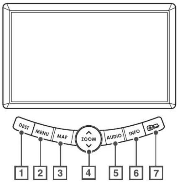
1 DEST
This button is used to display the destination screen of your navigation system. See the Owner's Manual Supplement for the navigation system.
2 MENU
This button is used to display the menu screen of your navigation system. See the Owner's Manual Supplement for the navigation system.
3 MAP
This button is used to switch the screen to a navigation system screen from any other screen. See the Owner's Manual Supplement for the navigation system.
4 ZOOM
This button is used to zoom in the map displayed on the screen.
5 AUDIO
This button is used to display the Audio or RSE (Rear Seat Entertainment) screen.
6 INFO
This button is used to display the vehicle information screen.
7
This button is used to adjust the brightness and contrast of the image as well as to display a calendar (see Page 36 through 39, 42). If the system has automatically turned down the brightness in order to prevent excessive brightness following the illumination of headlights or parking lights, pressing this button for more than one second will return the display to the standard brightness level.
For further details on the MENU, MAP and DEST buttons, refer to the Owner's Manual Supplement for the navigation system.
Displaying Vehicle Information Screen
The vehicle information screen provides a variety of information on your vehicle and driving. It also gives ways to program certain functions available in your vehicle.
1
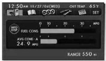
First, press the button, then select any of the keys on the screen.

The screen displays the current fuel consumption rate, average fuel consumption rate, and the range you can drive on the remaining fuel. See Pages 8 through 10.

The screen displays the driving record data. The monitor system can retain the record data. See Pages 11 through 20.

The screen displays the reading of the following three meters: average fuel consumption rate, current fuel consumption rate and throttle opening percentage. See Page 21.

You can program your maintenance schedule and other maintenance-related items from this screen. See Pages 22 through 25.

You can use a calculator. You can also convert units, for example, between miles and kilometers.

You can program certain monitor and other system functions. See Pages 26 through 33.
NOTE
- You can turn the outside air temperature display on or off in the map screen by selecting the SST See Page 26.
- You may not be able to use the vehicle information screen if data cannot be properly retrieved from the relevant vehicle systems.
Displaying Vehicle Information and Programming Vehicle System Functions
Displaying fuel consumption information and programming for the automatic alarm display
■Displaying fuel consumption information
Use the following procedure to display the current fuel consumption rate, average fuel consumption rate, and range you can drive on the remaining fuel.
Press the button.
1
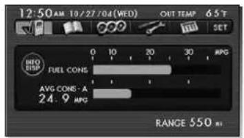
Select
The fuel consumption information screen will be displayed.
This completes the procedure.
NOTE
- Current and average fuel consumption rates will change all time due to driving and other conditions. The displayed data, including remaining fuel range data, may be different from the actual values. It is advisable that you refuel well in advance of reaching a displayed distance.
- Displayed current and average fuel consumption rates are based on estimates during running, not on accurate measurements.
- The average fuel consumption rate is associated with the driving after the last resetting of each trip meter. If the A or B trip meter is reset, the average fuel consumption rate will also be reset. After resetting the trip meter, the average fuel consumption rate will not be displayed until the vehicle has been driven approximately 1 mile from the reset point.
■Programming automatic alarm display for low remaining fuel level
You can program the display to make it automatically alert you of the correspondingly low fuel level remaining.
Press the button and then select

1
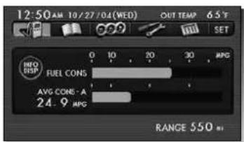
Select

2
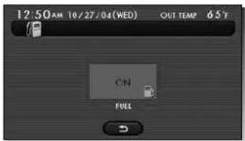
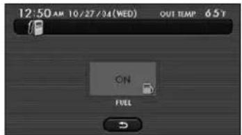
Select for the desired alarm display item ("FUEL"). The selected OFF should change to . ON
3
Select
This completes the procedure.
NOTE
- If is displayed for "FUEL" (remaining fuel level), the automatic alarm display function has been activated for that item. To deactivate the function, select . The indication should change from to .
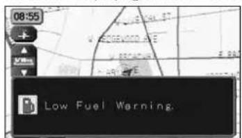
- The current fuel consumption rate alarm will be displayed only when the navigation screen is being used.
• The screen displaying an alarm looks like this:
Displaying, retaining, and erasing driving record data
■Displaying driving record data
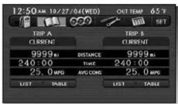
Use the following procedure to display the current driving record data (distance, time, and average fuel consumption rate).
Press the button.
1
Select
The driving record screen will be displayed.
This completes the procedure.
NOTE
- If a vehicle's trip meter is reset, the corresponding drive distance and time display ("TRIP A" or "TRIP B") will also be reset.
- The drive time display is associated with the amount of time the ignition switch has stayed on since the trip meter was reset.
- When the vehicle battery is removed for repair or other purposes, the time is reset, but the distance is not reset. To reset the distance, press the trip meter knob. Please refer to the vehicle owner's manual for further details.
• The maximum time display possible is 240 hours (10 days).
■Retaining driving record data
Use the following procedure to retain the current driving record data.
Press the button and then select.

1
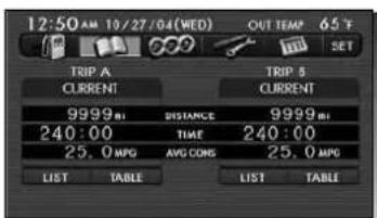
Select below the trip meter designation (TRIP A or TRIP B) of the driving record data you wish to keep.
2
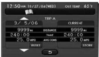
Select or to specify the number of the history frame (data storage location) where the driving record data are to be retained.
3
Select RESET.
4
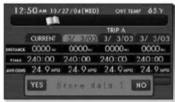
YES will appear, requesting you to confirm your selection. Select it.
5
Select
This completes the procedure.
NOTE
- A maximum of three different driving record data sets can be retained for each of the trip meters (TRIP A and TRIP B).
- Driving record data can be retained while viewing the retained driving record data list (see Page 17).
- If the data storage location (history frame) specified in Step 2 is already occupied by data, this data will be replaced with new data once you have confirmed Step 4.
- When driving record data have been successfully retained in a history frame, the history frame's heading will change from a number to the date of data retention.
■Erasing driving record data
Use the following procedure to erase retained driving record data.
Press the button and then select.

1
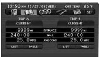
Select below the trip meter designation (TRIP A or TRIP B) about which you wish to erase the driving record data.
2
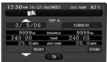
Select or to specify the number of the history frame (data storage location) where the driving record data to be erased are retained.
3
Select RESET.
4
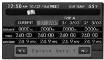
YES will appear, requesting you to confirm your selection. Select it.
5
Select
This completes the procedure.
NOTE
There is no way to restore erased driving record data. Please use this procedure with caution so as not to accidentally erase any important data.
■Displaying retained driving record data list
Use the following procedure to display a retained driving record data list.
Press the button and then select.

1
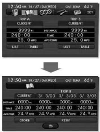
Select for the trip meter (TRIP A or TRIP B) about which you wish to display the list.
This completes the procedure.
NOTE
Selecting driving record data list screen will cause the monitor system to go back to the driving record screen.
■Retaining driving record data while viewing a retained driving record data list
Use the following procedure if you want to retain driving record data while viewing a relevant data list.
Press the button and then select.

1
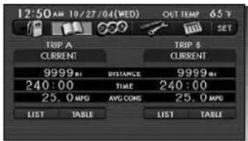
Select for the trip meter (TRIP A or TRIP B) about which you wish to retain the driving record data.
2
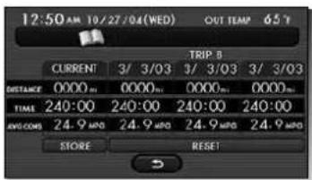
Select STORE.
3
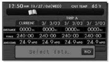
Select the history frame (data storage location) in which the data are to be retained.
4
YES will appear, requesting you to confirm your selection. Select it if the selection is correct.
5
Select
This completes the procedure.
NOTE
- A maximum of three different driving record data sets can be retained for each of the trip meters (TRIP A and TRIP B).
- When the data storage location (history frame) specified in Step 3 is already occupied by data, this data will be replaced with new data once you have confirmed Step 4.
- When the driving record data has been successfully retained in a history frame, the history frame's heading will change from a number to the date of the data retention.
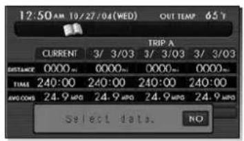
- Data retention is cancelled if you select No e "Select data" box NO
■Erasing driving record data while viewing a retained driving record data list
Use the following procedure if you want to erase retained driving record data while viewing a driving record data list.
Press the button and then select.

1
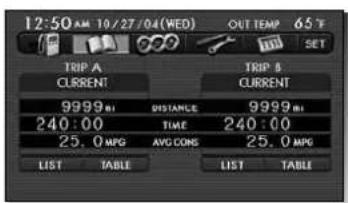
Select for the trip meter (TRIP A or TRIP B) about which you wish to erase the driving record data.
2
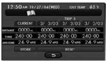
Select RESET
3
Select the history frame (data storage location) where the data to be erased are retained.
4
YES will appear, requesting you to confirm your selection. Select it.
5
Select
This completes the procedure.
NOTE
- There is no way to restore erased driving record data. Please use this procedure with caution so as not to accidentally erase any important data.
- Data erasure is cancelled if you select "NO" e "Select data" box NO
Displaying three meters
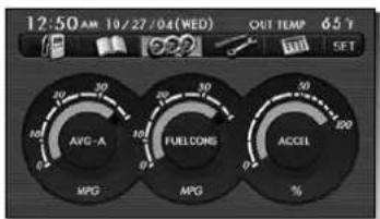
Use the following procedure to display the three meters showing the average fuel consumption rate, current fuel consumption rate and throttle opening percentage.
Press the button.
1
Select 999.
The three meters will be displayed on the screen.
This completes the procedure.
NOTE
- The average fuel consumption rate, current fuel consumption rate and throttle opening percentage indications are based on data retrieved from the relevant vehicle systems. For this reason, the status represented by meter readings may lag behind the current status.
- If data cannot be properly retrieved from the relevant vehicle systems, there will be no readings displayed on the meters.
Maintenance schedule
■Programming maintenance schedule
You can program your maintenance schedule into the monitor system for any of the following items, in terms of period and distance intervals.
- Maintenance
- Fluids check
- Tire pressure
- Engine oil
Use the following procedure:
Press the button.
1
Select
The maintenance information screen will be displayed.
2
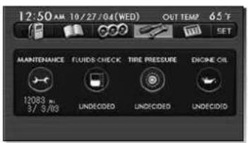
Select the item (maintenance, fluids check, tire pressure, or engine oil) for which you wish to program the schedule.
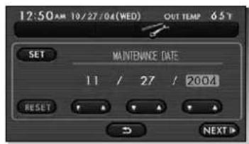
Select to enter the maintenance schedule date.
Select SET.
YES will appear on the screen. Select it if the date is correct.
Select NEXT.
Select to enter the maintenance schedule distance.
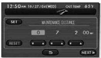
Select SET.
YES will appear on the screen. Select it if the distance is correct.
10
Select
This completes the procedure.
When a vehicle maintenance schedule is programmed
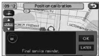
When a maintenance date alone is programmed, the monitor will remind you of the date by a message on the screen one month before, one week before, and on the day maintenance is due. When maintenance distance alone is programmed, a reminder message will be displayed 500 mile before, 100 mile before, and upon expiration of the distance. When both maintenance date and distance are programmed, the first message will be displayed upon reaching either the first date or distance, whichever comes earlier. This also applies to the second and third reminder times.
- If you want to dismiss the reminder message, select OK the reminder message box. The reminder message will not be displayed until reaching either the next date or distance, whichever comes first.
- If you want to display the reminder message later, select Lather a reminder message box. The reminder message will not be displayed until the engine is restarted.
NOTE
- You may program in either the date first (Steps 3 through 5) or distance (Steps 6 through 9). You may also program in a date or a distance only.
- Do not fail to select whether a date or distance has been entered, otherwise the entry will not be enabled.
- The date or distance entry can be cancelled by selecting RESET 3 or 7.
- The programmed date and/or distance will be displayed in the maintenance information screen.
- The icon(s) in the reminder messages for expired date and/or distance will be displayed in red.
- The date or distance entry can not be changed by selecting LATER
- An example of the reminder message is shown below.
When maintenance distance is programmed
- 500 miles or 100 miles before Service reminder.
- Upon expiration of maintenance distance Warning! Permitted service distance exceeded.
When a maintenance date is programmed
- One month or one week before Service reminder.
- On the programmed day Final service reminder.
• After the programmed day Warning! Permitted service time exceeded.
Programming vehicle system functions
■Programming display and answerback beep
You can program the monitor system for certain display items (see below) and answerback beep using the following procedure:
Press the button and then select.

1
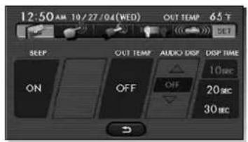
Select the display and beep programming screen will appear.
Select or set any of the following items.
BEEP
Selecting or deselecting this turns the beeps on or off in response to specific operations performed.
OUT TEMP
Selecting or deselecting this turns the outside air temperature displayed in the upper right corner of the map screen on or off.
AUDIO DISP
On display screens other than AUDIO-only, it is possible to display the AUDIO as a subtitle on the screen. The time display can be set to OFF (no display), 5 sec., 10 sec., or CONT. ON (continuous display). Please select the display time according to your preference. The initialized setting is 10 sec.
DISP TIME
Choose the display time for low fuel and other automatic alarms from 10, 20, and 30 seconds.
This completes the procedure.
NOTE
- Default settings for the above items vary depending on the vehicle model, version and grade.
- All selections and settings become effective as soon as they are made.
- The monitor system returns to the vehicle information screen when you select
- Beep selection is enabled only when a genuine SUBARU audio system is connected.
- Display time can be set for the following three automatic alarm items:
- Vehicle information
- Fuel remaining
- Messages on restrictions during driving ("prohibited while driving" etc.)
■ Touch panel sensing position adjustment
You can adjust the touch panel's sensing positions by using the following procedure:
Press the button and then select.

1
Select .
2
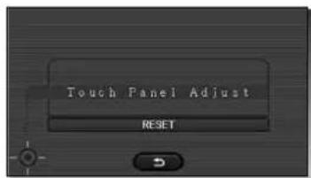
Touch the center of the lower-left crossmark
3
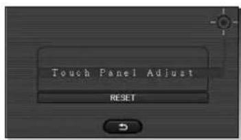
Touch the center of the upper-right crossmark
4
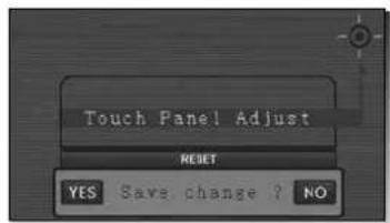
Select YES if you want to save the changes.
Select if you do not want to save the changes.
The monitor system will return to the vehicle information screen.
This completes the procedure.
NOTE
- If is selected after RESET or 3, following screen is displayed.
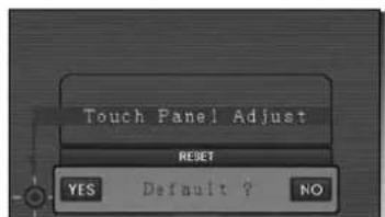
If YESlected, the touch panel's sensing positions will revert to the default positions.
If NO-lected, the touch panel's sensing positions will revert to the original positions.
- If you select a Step 2 or 3, you can return to the previous screen.
- The adjustment performed becomes effective as soon as you make it.
- At the time of delivery of the vehicle to the first user, the touch sensing positions are adjusted correctly. Use the above procedure if you feel that they have deviated from the correct positions.
■Keyless entry system programming
You can program certain items related to the keyless entry system using the following procedure:
Press the button and then select.

1
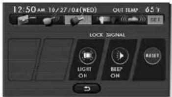
Select

Select or set the following items.
LOCK SIGNAL
The keyless entry system has an answerback signaling function, which notifies the driver by electronic chirp and the turn signal lights when locking or unlocking operation performed. Please select or deselect the activation or deactivation of the electronic chirp and turn signal lights. The electronic chirp can be selected using the "BEEP" icon, and the turn signal lights using the "LIGHT" icon.
RESET
Select this button to revert all settings performed on this screen to the default settings.
This completes the procedure.
NOTE
• Each setting becomes effective as soon as you make it.
- The monitor system returns to the vehicle information screen when you select
- The answerback signaling setting is only enabled when your vehicle has that function.
- For detailed information on how to operate the keyless entry system, refer to your vehicle owner's manual.
■Programming other vehicle system functions
You can program the vehicle system functions described below by using the following procedure:
Press the button and then select

1
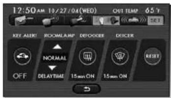
Select
Select or set the following items.
KEY ALERT
Select or deselect this key to enable or disable the key lock-in prevention function. Please see the vehicle owner's manual for details of the key lock-in prevention function.
ROOMLAMP (interior light)
You can choose the delay time before extinction of the interior light when the doors are unlocked using the keyless entry system transmitter, or when the doors are closed.
DEFOGGER
You can program the rear window defogger for two operation modes: continuous and 15-minute. When the continuous operation mode is programmed, the rear window defogger will operate for 15 minutes, stop for two minutes, and again operate for 15 minutes and so on. Even in under continuous operation mode, the defogger shuts off if certain conditions are met. (Refer to the vehicle owner's manual for these conditions.) In the 15-minute mode, the defogger will automatically shut off after about 15 minutes. You can shut it off before that time if you push the rear window defogger switch.
DEICER
You can program the windshield wiper deicer for two operation modes: continuous and 15-minute. When the continuous operation mode is programmed, pressing the windshield wiper deicer switch means that the deicer will continue to function. It will, however, stop operating automatically if certain conditions are met. (Refer to the vehicle owner's manual for these conditions.) In the 15-minute mode, the windshield wiper deicer will automatically shut off after about 15 minutes. You can shut it off before that time if you push the switch.
RESET
Select this key to revert all the three settings you performed on this screen to the default settings.
This completes the procedure.
NOTE
- All selections and settings become effective as soon as they are made.
- The monitor system returns to the vehicle information screen when you select
- Setting the windshield wiper deicer is only enabled when your vehicle has the windshield wiper deicer function.
- Interior light extinction delay time can be programmed as follows:
After unlocking doors with
keyless entry transmitter After closing doors
| 0 SEC 0 second 0 second |
| SHORT 35 seconds 12 seconds |
| NORMAL 35 seconds 22 seconds |
| LONG 35 seconds 32 seconds |
■Alarm system and shock sensor
You can activate or deactivate the alarm system and the dealer optional shock sensor. Also, you can select the monitoring start delay time and the sensitivity level for detection of impact to the vehicle.
Press the button and then select

1
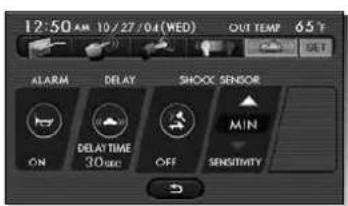
Select
Select or set the following items.
ALARM
Set the alarm system ON or OFF.
DELAY
Set the monitoring start delay time (after closure of doors).
SHOCK SENSOR
Use the ☐ on to select operation or non-operation. Select the sensitivity using the "SENSITIVITY" icon. Sensitivity can be selected from MIN to MAX, in a total of 11 gradations.
NOTE
- The settings for shock sensor can only be performed on a vehicle equipped with the dealer optional shock sensor.
- It takes around 5 seconds for the sensitivity level to be adjusted. During this time, the security indicator light will flash to indicate the adjustment is being performed.
- If the sensitivity adjustment has not been performed correctly, the buzzer (beeping sound) will sound four times. If the buzzer continues to sound frequently, please have the system inspected by a SUBARU dealer.
The calculator functions
A calculator with an 8-digit display is available. The calculator also performs unit conversions between miles and kilometers, pounds and kilograms, etc.

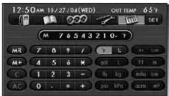
To perform a unit conversion, enter a number, then select the key for the unit you wish to convert from, then the key for the unit you wish to convert to.
Example: Convert 100 miles into kilometers: 100 [mile] [km] = 160.9 . km
Below is a description of each key and what it does.
| Key Description Action | |
| 0-9 Numbers The numbers 0 to 9 | |
| Decimal point Begin entering numbers below the decimal point | |
| = Equals sign Display the results of the calculation | |
| + Addition operator Perform addition | |
| - Subtraction operator Perform subtraction | |
| Key Description Action | ||
| ÷ Division operator Perform division | ||
| ×× | Multiplication operator Perform multiplication | |
| MR Memory recall Retrieve a number from memory, and overwriting the current display | ||
| M+ Memory add Add the currently displayed number to the memory | ||
| C | Clear | Clear the currently displayed number. If you have entered a number after pressing an operator, pressing this button returns the calculator to the state of having pressed the operator |
| AC | All clear | Return to the initial state (clear the current display, operator state, memory number, etc.) |
| °F | Fahrenheit | Convert the entered number from Celsius to Fahrenheit* |
| °C | Celsius | Convert the entered number from Fahrenheit to Celsius* |
| gal | Gallons | Convert the entered number from liters to gallons* |
| L Liters | Convert the entered number from gallons to liters* | |
| lb | Pounds | Convert the entered number from kilograms to pounds* |
| kg | Kilograms | Convert the entered number from pounds to kilograms* |
| mile | Miles | Convert the entered number from kilometers to miles* |
| km | Kilometers | Convert the entered number from miles to kilometers* |
| ft Feet | Convert the entered number from meters to feet* | |
| m | Meters | Convert the entered number from feet to meters* |
| in | Inches | Convert the entered number from centimeters to inches* |
| cm | Centimeters | Convert the entered number from inches to centimeters* |
| acre | Acres | Convert the entered number from square meters to acres* |
| m^2 | Square meters | Convert the entered number from acres to square meters* |
| psi | Pounds per square inch | Convert the entered number from kilopascals to pounds per square inch* |
| kPa | Kilopascals | Convert the entered number from pounds per square inch to kilopascals* |
* Results of unit conversions may include rounding errors.
The calendar functions
A calendar feature is available.
■Displaying calendar
Press the button.
1
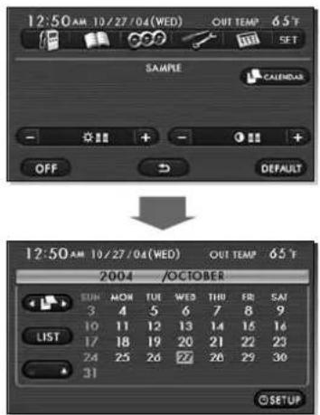
Select CALENDAR.
The calendar will appear.
A mark will appear on today's date.
NOTE
Use the arrow buttons ( ) to display the previous and following months.
■Adding a memo
You can add up to 20 memos to the calendar.
Press the button and then select CALENDAR.
1
Select LIST.
2
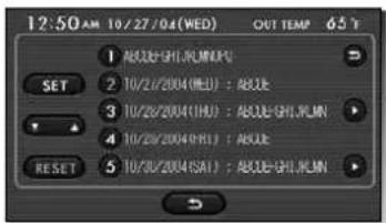
Select the slot you wish to add a memo to (1 to 20), then select SET.
NOTE
Use the up and down arrows (▼) show items
6 to 20.
3
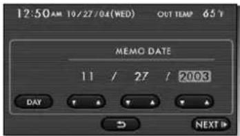
Set the date for the memo.
DAY : Enter a date in DD/MM/YYYY format. Example: 01/05/2005 "1 May 2005" will appear in the memo. [YEAR]: Enter a date in DD/MM format. Example: 01/05/---- "1 May every year" will appear in the memo. [MONTH]: Enter a day in DD format. Example: 01/- -/---- "01 of every month" will appear in the memo. [WEEK]: Enter a day of the week. Example: (MON) "Monday of every week" will appear in the memo.
4
Select NEXT.
5
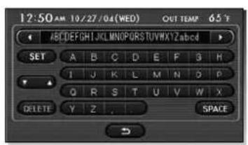
Enter the text of the memo, and select SET

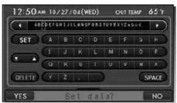
YES will appear on screen. Select it if the date is correct. Select YES.
6
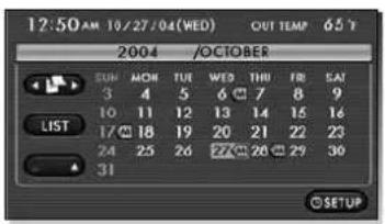
Select ↩.
The memo icon will appear on the calendar.
■Deleting a memo
Press the button and then select.
CALENDAR
Select LIST.
Select a memo to delete from the list, then select RESET
Select YES.
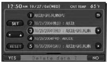
Select
Displaying Satellite Radio Source
You can display the satellite radio source when the audio unit is in the satellite radio source mode.
NOTE
- Satellite radio can only be operated with the audio unit.
- For detailed instructions on the operation of the audio unit, see the owner's manual furnished with the vehicle.
1
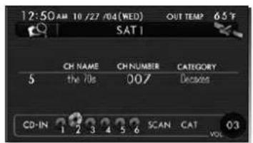
The screen displays a convenient mode as the initial setting.
2
Select
3
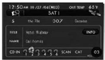
The screen displays a source mode.
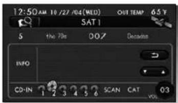
Select INFO.
The screen displays another source mode.
Select → to return the screen of step 3.
Select
The screen displays the satellite radio channel preset list screen.
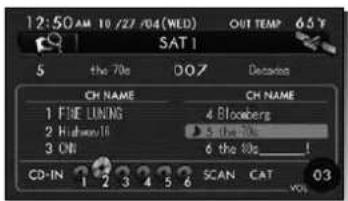
Select 📄 to return the screen of step 1.
Adjusting Brightness/Contrast
Adjusting brightness/contrast
Use the following procedure to adjust the brightness/contrast of the image on each screen:
1
Press the button.
2
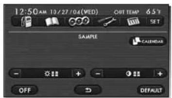
Adjust the image contrast/brightness as follows:
Select 📋 and then or → adjust the brightness.
Select and then or to adjust the contrast.
3
Select
The previous screen will be displayed.
This completes the procedure.
NOTE
- All adjustments take effect as soon as you make them and can be visually confirmed.
- The system saves the adjustments for individual screens (vehicle information screen and navigation screen) as well as for a situation with and without illumination from headlights or parking lights.
CAUTION
Use of controls or adjustments or performance of procedures other than those specified herein may result in hazardous radiation exposure.
In compliance with Federal Regulations, following are reproductions of labels on, or inside the product relating to laser product safety.
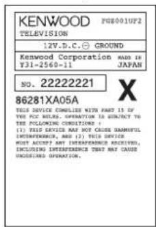
Location : Monitor top surface
FCC WARNING
This equipment may generate or use radio frequency energy. Changes or modifications to this equipment may cause harmful interference unless the modifications are expressly approved in the instruction manual. The user could lose the authority to operate this equipment if an unauthorized change or modification is made.
NOTE
This equipment has been tested and found to comply with the limits for a Class B digital device, pursuant to Part 15 of the FCC Rules. These limits are designed to provide reasonable protection against harmful interference in a residential installation. This equipment may cause harmful interference to radio communications, if it is not installed and used in accordance with the instructions. However, there is no guarantee that interference will not occur in a particular installation. If this equipment does cause harmful interference to radio or television reception, which can be determined by turning the equipment off and on, the user is encouraged to try to correct the interference by one or more of the following measures:
- Reorient or relocate the receiving antenna.
- Increase the separation between the equipment and receiver.
- Connect the equipment into an outlet on a circuit different from that to which the receiver is connected.
- Consult the dealer or an experienced radio/TV technician for help.
NOTE
This Class B digital apparatus complies with Canadian ICES-003.
Foreword
This booklet is a supplement to the Owner's Manual for SUBARU B9 TRIBECA and contains a detailed description and instructions for proper operation of the Rear Seat Entertainment System provided in your vehicle.
To ensure optimum and correct use of your Rear Seat Entertainment System, please read this supplement and get acquainted with the system before using it.
Please keep this supplement together with your Owner's Manual and leave it in the vehicle at the time of resale. The next owner will need the information it contains.
What You Can Enjoy with Your Rear Seat Entertainment System 6
Display 7
■ How to open and close the display ....7
- Keeping the display clean ....9
Remote Control 10
■ Control buttons and joystick ....12
■ How to use the remote control ....14
■ Replacing the battery ....16
Wireless Headphones 18
■ Replacing the batteries ....20
DVD Player 22
Precautions to Observe When Handling Discs .....23
Types of Discs Playable with the Rear Seat Entertainment System 23
■ DVD video discs ....25
■ Copyright 26
Playing Discs 27
Playing DVD Video Discs 27
■ Starting playback 27
■ Stopping playback 27
■ Pausing 27
■ Fast-forwarding 28
■ Fast-reversing 28
■ Skipping chapters forward .....29
■ Skipping chapters backward .....29
■ Title search ....30
■ Skipping to a predetermined screen ....31
■ Displaying each disc's menu on the screen ....31
■ Changing the audio language ....32
■ Changing the subtitle language ....33
■ Image angle selection on multi-angle recorded scenes .....34
■ Selecting a dynamic range control setting ....35
Playing Video CDs 36
■ Starting playback 36
■ Stopping playback 36
■ Pausing ....36
■ Fast-forwarding ....37
■ Fast-reversing 37
■ Skipping tracks forward ....38
■ Skipping tracks backward ....39
■ Skipping to a predetermined screen
(Ver 2.0 video CD only) ....39
■ Sound channel (MAIN/SUB) selection ....40
Playing Music CDs 40
■ Starting playback 40
■ Stopping playback 40
■ Fast-forwarding 41
■ Fast-reversing ....41
■ Skipping tracks forward 42
■ Skipping tracks backward ....42
■ Repeat playback 43
■ Random playback 43
■ Scan 44
Contents
Initial Settings ....45
Setting DVD/Audio/Subtitle Language 46
Setting the Angle Mark Display 47
Setting the Viewer Restriction Level 48
■ Password registration 49
Connecting External Devices to Your Rear Seat Entertainment System ....50
Adjusting Display Conditions and Selecting Display Mode ....51
Display Condition Adjustment 51
■ Adjusting method 51
Display Mode Selection 52
■ Selecting method 53
Error Messages ....54
Language/Code List 55
Safety Warnings
You will find a number of WARNINGS, CAUTIONs and NOTES in this supplement.
These safety warnings alert you to potential hazards that could result in injury to you or others.
Please read these safety warnings as well as all other portions of this supplement carefully in order to gain a better understanding of how to use your Rear Seat Entertainment System safely.
WARNING
A WARNING indicates a situation in which serious injury or death could result if the warning is ignored.
CAUTION
A CAUTION indicates a situation in which injury or damage to your vehicle including the Rear Seat Entertainment System, or both, could result if the cautions is ignored.
NOTE
A NOTE gives information or suggestions how to make better use of your Rear Seat Entertainment System.
Before Use
WARNING
- Never try watching videos or using other entertainment programs with your Rear Seat Entertainment System by keeping the vehicle engine running in a garage or other enclosed area. Exhaust gases accumulated in such an area or entering the vehicle are dangerous, or even lethal.
- The driver must not attempt to operate or watch the Rear Seat Entertainment System while the vehicle is in motion. Doing so will distract attention from driving and the road, and could lead to an accident.
- The driver must not use headphones. Wearing headphones shuts out or drowns out outside sounds and reduces the driver's awareness of dangerous situations, which increases the risk of having an accident.
- If you wish to park your vehicle and enjoy an entertainment program on this system, select a safe place that does not hinder traffic and has no parking ban.
CAUTION
The display, a component of the Rear Seat Entertainment System, contains mercury. For that reason, it is necessary to remove display before vehicle disposal. Once removed, please reuse, recycle or dispose of the display as hazardous waste.
NOTE
- Using the Rear Seat Entertainment System with the engine stopped could lower the battery's electricity level. If the initial charge level were too low, the next engine starting would be impossible. It is recommended that the system be used only when the engine is running.
- The display screen turns off if you start the engine while using the Rear Seat Entertainment System with the ignition switch in the "ACC" or "ON" position and the engine not in operation. To turn on the display again, press the "DVD·CD" button on the remote control. The image will re-appear on the screen.
- Liquid-crystal displays may be difficult to read when wearing polarized glasses.
System Components
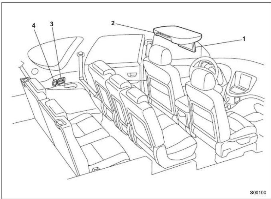
The Rear Seat Entertainment System consists of the following components:
1) Display (Refer to Page 7.)
2) DVD player (Refer to Page 22.)
3) External device jacks (Refer to Page 50.)
4) Accessory power outlet (Refer to Page 50.)
In addition to the components listed above, there is a remote control and two sets of wireless headphones as attachments to the system.
Basic Operations
What You Can Enjoy with Your Rear Seat Entertainment System
- The Rear Seat Entertainment System is designed to provide your vehicle's rear-seat passengers with video and music entertainment programs recorded on DVD video discs, video CDs and music CDs.
- The Rear Seat Entertainment System will operate when the ignition switch is in the "ACC" or "ON" position.
- Playback sounds can be listened to by using the wireless headphones accompanying the system.
- All operations with the Rear Seat Entertainment System can be managed using the remote control accompanying the system (except when ejecting a disc).
- Replacements of the dedicated headphones and remote control are available from your SUBARU dealer should you lose them.
- You can also enjoy TV games from a home-use TV game machine or video programs from a video tape player with the Rear Seat Entertainment System if such an external device is connected to one of the external device jacks of the system. For further details, refer to the instruction manual provided by the manufacturer of each external device.
NOTE
- When the vehicle is parked with the parking brake applied and the selector lever in the "P" position, you can enjoy video programs on the navigation display on the dashboard if you press the "AUDIO" button on the navigation control panel. This does not apply when the vehicle is in motion.
- If you press the "AUX/RSE" button on the audio panel, playback sounds from this system will be outputted through the vehicle's speakers.
Display
■ How to open and close the display
|
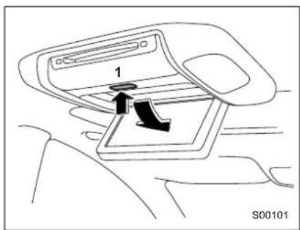
1) Release button
Push the release button to open the display.
The display will swing down partway along its full swing angle.
|
natural_image
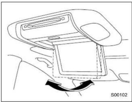
Line drawing of a car interior showing the seat and armrest (no text or symbols)Adjust the display to the desired angle.
1
natural_image
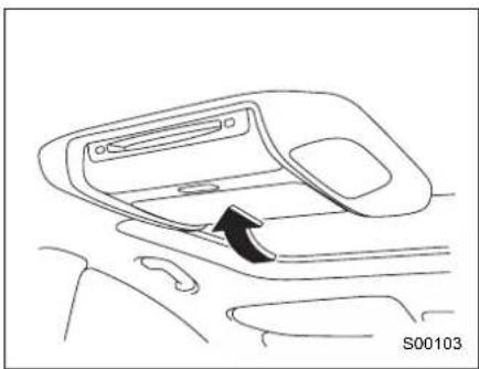
Line drawing of a car interior showing the dashboard and seat area with an arrow indicating direction (no text or symbols)To close the display to its storage position, swing and push it up until it locks.

CAUTION
Close the display when it is not in use to help reduce the chance of injury in the event of an accident or sudden stop.
- Keeping the display clean
Do not touch the display screen with bare hands. The display screen is easily soiled with hand grease.
Use a soft, dry cloth to clean the display screen surface. Do not use organic solvents.
The screen surface is sensitive to scratches or other physical damage. Avoid pushing on it strongly or rubbing it with a hard cloth or any other scratchy material.
NOTE
- The screen is made of a liquid crystal display (LCD) panel. When the system is turned on in an extremely low outside temperature, the LCD takes a relatively long time to become bright. On the other hand, when the outside temperature is high, the LCD may become darker than usual. Both conditions are normal.
- Images on an LCD screen may contain some tiny black spots and/or bright spots. They reflect a characteristic normal to the LCD and do not indicate any abnormal condition.
Remote Control
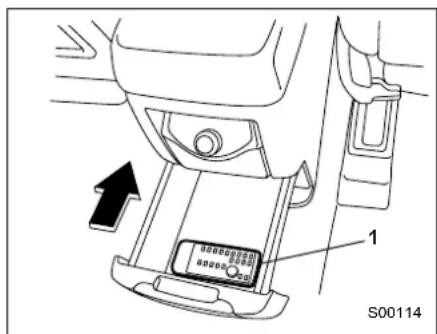
1) Remote control
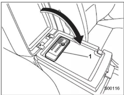
1) Remote control
The Rear Seat Entertainment System can be operated only using the remote control (except when ejecting a disc). Touching a switch on the display screen directly with your finger does not have any effect.
CAUTION
- Store the remote control in the center or rear console box when the Rear Seat Entertainment System is not being used to reduce the chance of injury in case of an accident or sudden stop.
- Be sure to keep the rear console box as well as the upper compartment of the center console box closed to reduce the chance of injury in case of an accident or sudden stop.
- Do not disassemble or modify the remote control. Doing so could cause an accident, fire or electric shock.
- Do not expose the remote control to direct sunlight, strong heat and/or a highly humid environment. The remote control case could become deformed and the battery in it could leak or even explode if exposed to these conditions.
- Avoid dropping the remote control and hitting it against hard objects.
- Do not sit or step on the remote control. Placing anything heavy on it should also be avoided.
- Avoid pressing the remote control buttons for longer than necessary, as the battery is consumed while any button is kept pressed. Also avoid placing an object on the remote control, as it may press buttons and reduce the battery life.
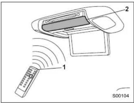
1) Signal emitting eye
2) Signal reception window
To use the remote control, direct its signal-emitting eye toward the signal reception window of the display.
■ Control buttons and joystick
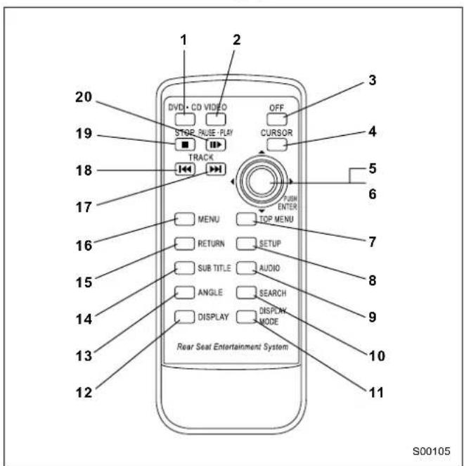
1) DVD·CD button
When this button is pressed, the Rear Seat Entertainment System turns on. The display will show DVD mode or CD mode.
2) VIDEO button
When this button is pressed, the system will accept and operate on the video signal from an external video device connected to the system.
3) OFF button
When this button is pressed, the Rear Seat Entertainment System turns off.
4) CURSOR button
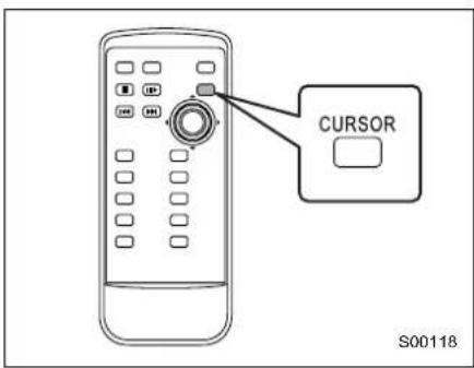
When this button is pressed, control switches will appear on the display when the player is in operation.
5) Joystick
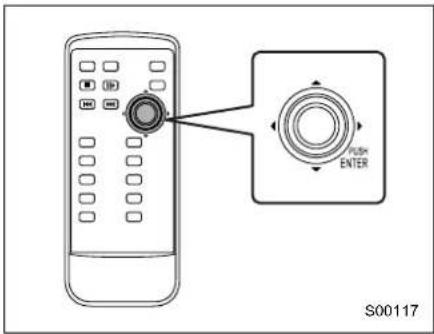
The joystick is used to highlight a control switch or a menu item on the screen and also to make an entry. Click an appropriate one of its four arrow-marked ends (▲, ▶ and ◀) to use it.
6) ENTER button
When this button is pressed, the system will execute a selection or entry that was made with the joystick.
7) TOP MENU button
When this button is pressed, the title selection screen for the DVD video disc currently in the player will appear on the display.
8) SETUP button
When this button is pressed, the initial setup screen will appear on the display, where you can make your initial settings.
9) AUDIO button
I
When this button is pressed, the desired audio language or MAIN/SUB sound channel can be selected when the player is in operation.
10) SEARCH button
When this button is pressed, the title search screen will appear on the display when the player is in operation. You can then start playback beginning with the title you have selected on the screen.
11) DISPLAY MODE button
When pressed, this button allows you to select the screen size.
12) DISPLAY button
|
When this button is pressed, the display condition adjustment screen will appear, where you can adjust the brightness, contrast, color and tone for images.
13) ANGLE button
When this button is pressed, the angle selection screen will appear, where you can select a desired angle when the player is reproducing a multi-angle recorded DVD video disc.
14) SUBTITLE button
When this button is pressed, the subtitle language selection screen will appear, where you can select a desired subtitle language when the player is playing a DVD video disc.
15) RETURN button
When this button is pressed, the disc will skip to a predetermined screen.
16) MENU button
When this button is pressed, the menu screen will appear for the DVD video disc currently in the player.
17) TRACK (▶) button
Each brief push (less than 1 second) of this button during operation of the player advances the video scene chapter by chapter. If you push the button continuously, the scene advances continuously and quickly (but slowly when playback is in pause mode) until you release the button.
Each brief push (less than 1 second) of this button during operation of the player reverses the video scene chapter by chapter. If you push the button continuously, the scene reverses continuously and quickly (but slowly when playback is in pause mode) until you release the button.
This button stops playback when it is pressed during operation of the player.
20) PAUSE • PLAY (Button
Pressing this button pauses playback when the player is in operation. Pressing it again restarts playback.
■ How to use the remote control
|
|
You can control the operation of the DVD player using the buttons on the remote control.
You can also control the player using the joystick on the remote control to highlight a switch on the display screen and then pressing the "ENTER" button. You cannot, however, control the player by touching a switch on the screen with your finger. When a switch is selected with the joystick, the color of the switch changes from blue to white. When you then press the "ENTER" button, your selection is executed.
To make control switches appear on the screen when playing a DVD video disc or video CD:
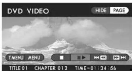
You can use the "CURSOR" button on the remote control to make the control switches appear on the screen. The control switches shown on the next page will be displayed when the button is pressed.
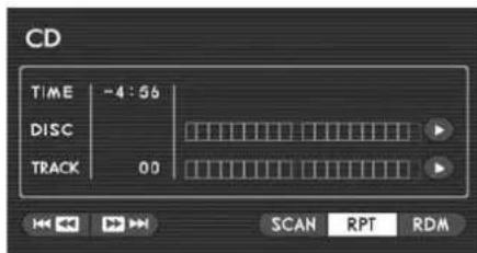
To make control switches appear on the screen when playing a music CD:
When a music disc is loaded in the player, playback will start automatically and the control switches shown on the next page will appear on the screen without the need for operating the remote control.
DVD Video Menu 1
DVD Video Menu 2
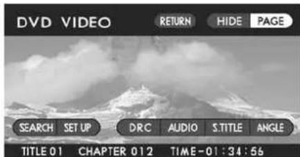
When playing a DVD video disc, different control switches are displayed on the screens for Menu 1 and Menu 2 (Menu 1 screen appears first when the "CURSOR" button is pressed). Switch between the two screens when necessary by highlighting the "PAGE" switch on the screen with the joystick and then pressing the "ENTER" button.
To make the switches disappear from the screen, push the remote control's "CURSOR" button again or highlight the "HIDE" switch on the screen with the joystick and then press the "ENTER" button. If you highlight and execute the "HIDE" switch, the TITLE number, CHAPTER number and playback time at the bottom of the screen also disappear.
Video CD Menu
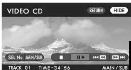
To make the switches disappear from the screen, push the remote control's "CURSOR" button again or highlight the "HIDE" switch on the screen with the joystick and then press the "ENTER" button. If you highlight and execute the "HIDE" switch the TRACK number and playback time at the bottom of the screen also disappear.
NOTE
The "RETURN" switch is displayed on the VIDEO CD menu only when you play a video CD version 2.0.
Music CD Menu
NOTE
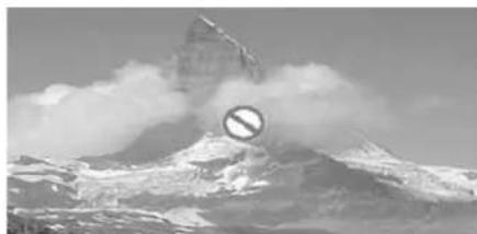
natural_image
Snow-covered mountain peak with a prominent snowhole symbol in the foreground (no text or symbols on the main image)If the "mark" appears on the screen when you select a control switch, it will not be possible to select or execute the switch.
■ Replacing the battery
WARNING
Take great care not to allow children to swallow batteries or any other removed part, as these could cause serious injury or death if swallowed.
CAUTION
Do not let dust, oil or water get on or in the remote control when replacing the battery.
When the battery begins to get weak, the signal transmission range of the remote control becomes shorter. If this is the case, replace the battery as soon as possible.
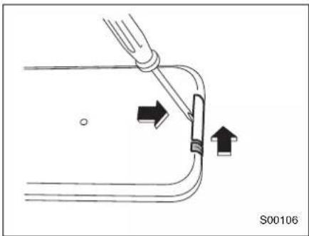
While holding the battery holder pushed in the direction of the arrow with your fingernail inserted in the slot, slide out the holder in the direction of the arrow using a cross-head mini screwdriver.
|
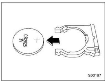
Remove the battery from the holder.
|
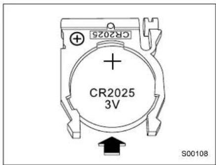
Install a new battery (Type CR2025 or equivalent) in the holder. Make sure the battery's positive (+) side and the "+" mark on the holder are on the same side. Slide the battery holder into the remote control until it clicks.
Wireless Headphones
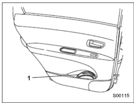
Use the wireless headphones to listen to audio outputted from your Rear Seat Entertainment System.
natural_image
Technical line drawing of a car door and side panel showing internal components (no text or symbols)1) Wireless headphone

CAUTION
- Store the headphones in a door pocket when they are not being used in order to reduce the chance of injury in case of an accident or sudden stop.
- Do not disassemble or modify the headphones. Doing so could cause an accident, fire or electric shock.
- Do not expose the headphones to direct sunlight, strong heat and/or a highly humid environment. The headphones could become deformed and the batteries in them could leak or even explode under these conditions.
- Avoid dropping the headphones and hitting them against hard objects.
- Do not sit on the headphones or place anything heavy on them.
- Human voices may have been recorded intentionally at low levels in some DVDs for special acoustic effects. If you carelessly adjust the volume in order to hear these voices more clearly, your ears may be exposed to unexpectedly loud sounds at a later point. This may also happen when you switch to a different audio source. Very loud sounds could damage your hearing and pose a driving hazard. Keep this in mind when you adjust the volume.
natural_image
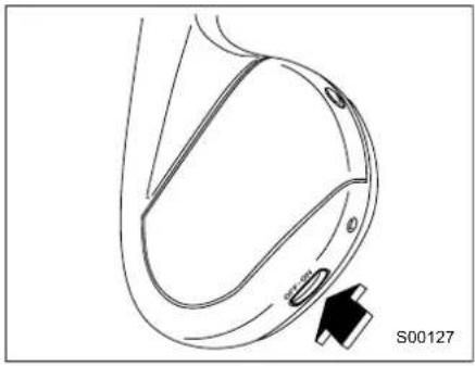
Technical line drawing of a mechanical component with a black arrow pointing to a feature labeled S00127 (no text or symbols beyond label)Press the "OFF • ON" button on the left earpiece to turn on the headphones: the power lamp on the right earpiece will come on.
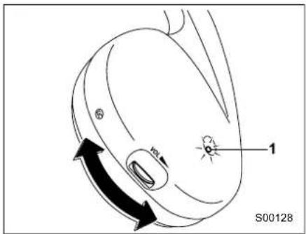
Adjust the sound level as desired with the volume dial on the right earpiece.
1) Power lamp
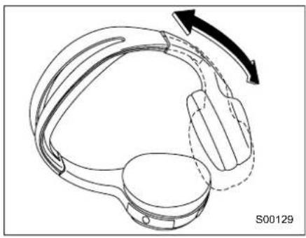
natural_image
Technical line drawing of a helmet with a rotating arrow indicating rotation (no text or symbols)Adjust the earpieces to comfortable positions by extending or retracting the headband.
NOTE
For longer battery life, turn off the headphones whenever they are not being used. Press the "OFF • ON" button to turn off the headphones and make sure the power lamp has gone out.
■ Replacing the batteries
WARNING
Take great care not to allow children to swallow batteries or any other removed part, as these could cause serious injury or death if swallowed.
CAUTION
Do not let dust, oil or water get on or in the headphones when replacing the batteries.
When the batteries begin to get weak, the power lamp will not come on even if you press the "OFF • ON" button. If this is the case, replace the batteries as soon as possible.
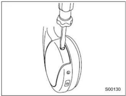
natural_image
Line drawing of a mechanical device with a screwdriver inserted into a circular component (no text or symbols)Remove the battery cover on the left earpiece by loosening the screw with a flat-head screwdriver.
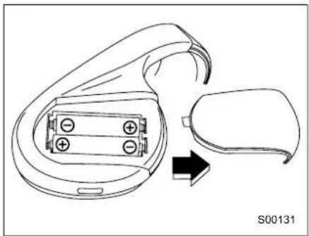
natural_image
Diagram of a device with battery pack and external casing, showing a right-hand rule for change (no text or symbols)Remove the old batteries and install new ones (two AAA batteries). Pay careful attention to the (+) and (−) marks on the battery case. Reinstall the cover in position by tightening the screw with a flat-head screwdriver.
DVD Player
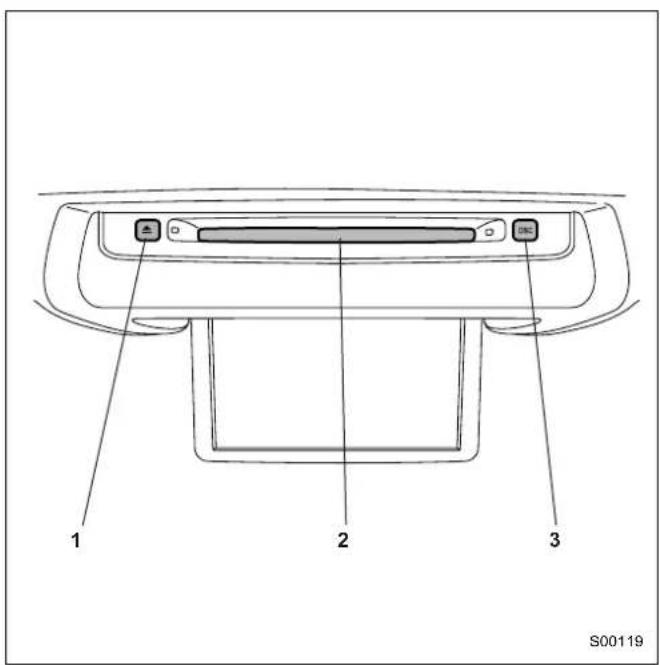
The DVD player can be operated when the ignition switch is in the "ACC" or "ON" position. Load a disc by inserting it into the disc slot of the player, with the label side facing up. The disc will be carried inward automatically when you insert it partially. The disc indicator light will turn on when the disc reaches the full inward position. To eject the disc, press the "Eject (▲) button. The disc will come out and the indicator light will go out.
1) Eject button
2) Disc slot
3) Disc indicator light
Precautions to Observe When Handling Discs
Types of Discs Playable with the Rear Seat Entertainment System
Your Rear Seat Entertainment System can play back music CDs, DVD video discs and video CDs that have any of the marks indicated below.
NOTE
- The system is not compatible with DVD audio discs and MP3-file or WAV-file based music CDs.
- The system does not support 8-cm/3-inch CDs; if inserted, they will automatically be ejected.
| Music CDs | |
| DVD video discs | |
| Video CDs |
The following products may not play back on the Rear Seat Entertainment System.
SACD
CCCD
Dual disc
CD-R
CD-RW
CD-ROM
DVD-R
DVD+R
DVD-RW
DVD+RW
DVD-ROM
DVD-RAM
When handling discs, follow these precautions:
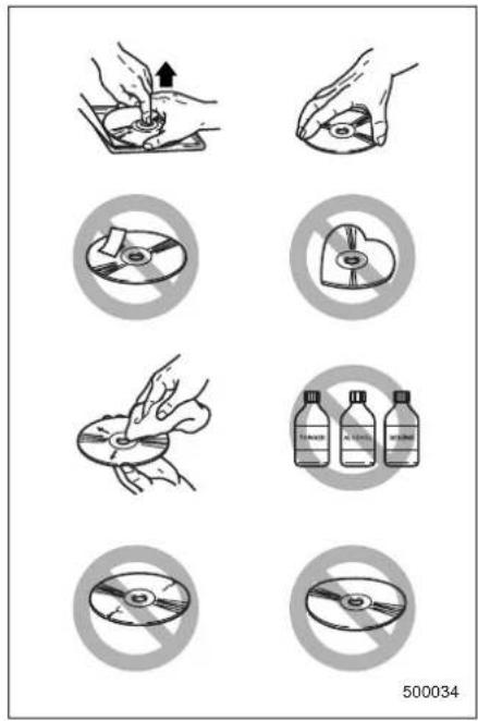
- In cold and/or rainy weather, condensation can form inside the DVD player, preventing normal operation. If this happens, eject the disc and wait for the player to dry out.
- Skipping may occur when the DVD player is subjected to severe vibration (for example, when the vehicle is driven on a rough surface).
- To remove a disc from its case, press the center of the case and hold both edges of the disc. If the disc surface is touched directly, contamination could cause poor image or sound quality. Do not touch the disc surface.
- Use a clean disc whenever possible. If there are any deposits, wipe the disc surface from the center outward with a dry, soft cloth. Be sure not to use a hard cloth, thinner, benzene, alcohol, etc.
- Do not use any disc that is scratched, deformed, transparent/semi-transparent, glue-labeled, or cracked. Also, do not use any disc that has a non-standard shape (for example, a heart shape) or 8-cm/3-inch CDs. Malfunctions or other problems might result.
- Discs are vulnerable to heat. Never keep discs in places exposed to direct sunlight, near heaters or in vehicles parked in the sun or on hot days.
DVD video discs
The DVD player of your Rear Seat Entertainment System can play back DVD video discs that conform to NTSC color TV formats. Any DVD video discs produced conforming to other formats such as PAL or SECAM cannot be used with the player.
The following are example logos that may be indicated on DVD video discs and what they mean:
 | The disc conforms to NTSC format of color TV. |
 | The disc has two audio tracks. |
 | The disc's subtitles are available in two languages. |
 | The disc's multi-angle recorded scenes are viewable from three different angles. |
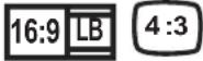 | Two screen aspect ratios (ratio of width to height) are selectable: wide screen of 16:9 and standard screen of 4:3. |
 | Region code indicating the area in which this video disc can be played. “ALL” stands for all countries; “1” stands for the United States and Canada. |
NOTE
Some DVD video discs have a region code, each indicating where it can be used. If a disc is not labeled "ALL" or "1", you cannot use it in your system's DVD player. If you attempt to play it in the player, a "REGION CODE ERROR" message will appear on the screen. Some DVD video discs without any region code may not be usable with your system's DVD player.
Copyright

The Dolby system is manufactured under license from Dolby Laboratories.
Dolby, DOLBY, and the double-D symbol are trademarks of Dolby Laboratories.
The Rear Seat Entertainment System incorporates copyright protection technology that is covered by method claims of certain U.S. patents and other intellectual property rights owned by Macrovision Corporation and other rights owners. Use of this copyright protection technology must be authorized by Macrovision Corporation, and is intended for home and other limited viewing uses only, unless otherwise authorized by Macrovision Corporation. Reverse engineering and modification is prohibited.

"dts" is a trademark of Digital Theater Systems, Inc.
Playing Discs
Playing DVD Video Discs
■ Starting playback
With the vehicle's ignition switch in the "ACC" or "ON" position, insert the disc into the disc slot of the DVD player, with the label side facing up. The player automatically starts playback of the disc. If a disc is already in the player, press the "DVD · CD" button on your remote control to start playback.
■ Stopping playback
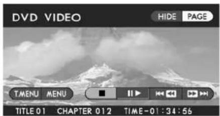
Method using screen and remote control:
Highlight the "■" switch on the screen with your remote control joystick, then press the "ENTER" button.
Method using remote control alone:
Press the remote control "STOP (■)" button.
■ Pausing
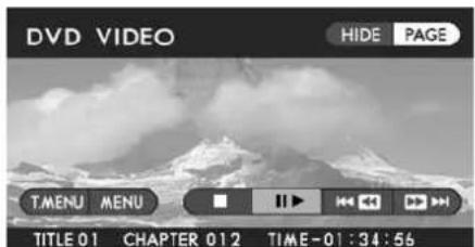
Method using screen and remote control:
Highlight the "▶" switch on the screen with the remote control joystick, then press the "ENTER" button.
Method using remote control alone:
Press the remote control "PAUSE • PLAY (I) button.
To restart playback, perform either of the above operations again.
■ Fast-forwarding
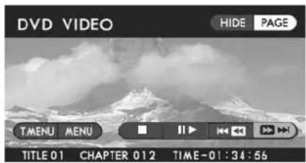
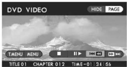
Fast-reversing
Method using screen and remote control:
Highlight the “▶▶▶” switch on the screen with the remote control joystick, then press the “ENTER” button continuously until reaching the desired scene.
Method using remote control alone:
Press the remote control "TRACK (▶▶)" button continuously until reaching the desired scene.
When you perform either of the above operations while the player is in pause mode, the disc will advance slowly.
Method using screen and remote control:
Highlight the "KKK" switch on the screen with the remote control joystick, then press the "ENTER" button continuously until reaching the desired scene.
Method using remote control alone:
Press the remote control "TRACK (◀◀)" button continuously until reaching the desired scene.
When you perform either of the above operations while the player is in pause mode, the disc will reverse slowly.
■ Skipping chapters forward
The data recorded on DVD video discs is divided into fragments called "titles", and each title is further divided into smaller fragments called "chapters". These titles and chapters are given specific numbers, which are indicated in the guide accompanying each disc. You can skip chapter(s) using the following procedure:
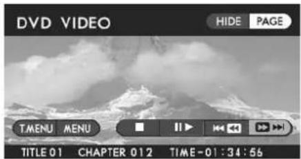
Method using screen and remote control:
Highlight the "▶ switch on the screen with the remote control joystick, then briefly press the "ENTER" button. The disc skips the current chapter and advances to the beginning of the next chapter. Repeat this operation as many times as necessary to reach the desired chapter.
Method using remote control alone:
Briefly press the remote control "TRACK (▶) button. Refer to the above for the subsequent process and operation.
■ Skipping chapters backward
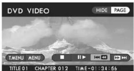
Method using screen and remote control:
Highlight the "K" switch on the screen with the remote control joystick, then briefly press the "ENTER" button. The disc reverses to the beginning of the current chapter. If you briefly press the button again, the disc reverses to the beginning of the preceding chapter. Repeat this operation as many times as necessary to reach the desired chapter.
Method using remote control alone:
Briefly press the remote control "TRACK (") button. Refer to the above for the subsequent process and operation.
■ Title search
If you enter a desired title number using the remote control joystick, the disc is played back beginning with the specified title. The number of titles differs from disc to disc. Refer to the guide attached to each disc for its title numbers.
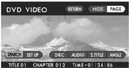
Method using screen and remote control:
Highlight the "SEARCH" switch on the screen with the remote control joystick, then press the "ENTER" button. The display switches to the title number entry screen.
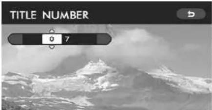
Enter the title number using the remote control joystick, then press the "ENTER" button. The player will play back the disc beginning with the specified title. To revert to the original video screen, highlight the "Switch" with the joystick, and then press the "ENTER" button.
Method using remote control alone:
Press the remote control "SEARCH" button. Refer to the above for the subsequent process and operation.
■ Skipping to a predetermined screen
You can start playing a disc beginning with a registered predetermined screen. Some discs may not be compatible with this function. For the predetermined screen of each disc, refer to the guide accompanying it.
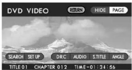
Method using screen and remote control:
Highlight the "RETURN" switch on the screen with the remote control joystick, then press the "ENTER" button. Playback will start at the predetermined screen.
Method using remote control alone:
Press the "RETURN" button on the remote control. Playback will start at the predetermined screen.
■ Displaying each disc's menu on the screen
You can display the menu stored in the disc.
Menus and their contents differ from disc to disc. After displaying a menu using the method below, follow the indications that each disc will show on its screen. Some discs may not allow you to select the top menu. For further details, please refer to the guide accompanying each disc.
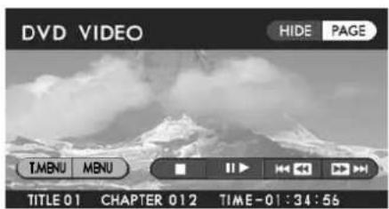
Method using screen and remote control:
With the remote control joystick, highlight the "T. MENU" switch on the screen when displaying the top menu, or the "MENU" switch when displaying other menus. Then press the remote control "ENTER" button. The top menu or other menus will appear on the screen.
Method using the remote control alone:
Press the "TOP MENU" button to display the top menu, or the "MENU" button to display other menus.
■ Changing the audio language
You can select a desired audio language from those available with the disc currently loaded in the player.
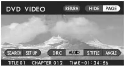
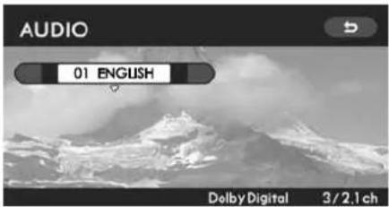
Method using screen and remote control:
Highlight the "AUDIO" switch on the screen with the remote control joystick, then press the "ENTER" button. The display will switch to the audio language selection screen.
Click the “▼end of the remote control joystick to highlight the desired language on the screen and then press the “ENTER” button. To revert to the original video screen, highlight the “Switch with the joystick, and then press the “ENTER” button.
Method using remote control alone:
Press the remote control "AUDIO" button. Refer to the above for the subsequent operation.
■ Changing the subtitle language
You can select a desired subtitle language from those available with the disc currently in the player.
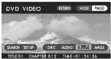
Method using screen and remote control:
Highlight the "S. TITLE" switch on the screen with the remote control joystick, then press the "ENTER" button. The display will switch to the subtitle language selection screen.
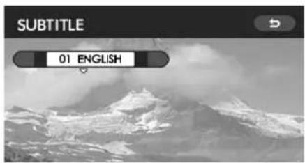
Click the "▼" end of the remote control joystick to highlight the desired language on the screen, then press the "ENTER" button. To revert to the original video screen, highlight the "▼" switch with the joystick, and then press the "ENTER" button.
Method using remote control alone:
Press the "SUBTITLE" button on the remote control. Refer to the above for the subsequent operation.
NOTE
If you select "OFF" in the above operation, no subtitle is displayed on the screen.
■ Image angle selection on multi-angle recorded scenes
If you play back a DVD video disc containing scenes recorded using the multi-angle technology, you can enjoy viewing them from different angles. For example, you can view the image of the same mountain from both the right and left sides. Some discs may not be compatible with this function.
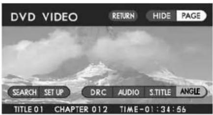
Method using screen and remote control:
Highlight the "ANGLE" switch on the screen with the remote control joystick, then press the "ENTER" button. The display will switch to the angle selection screen.
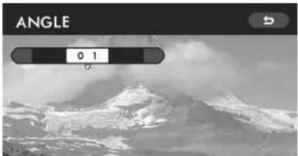
Click the "√end of the remote control joystick to highlight the desired angle on the screen, then press the "ENTER" button. To revert to the original video screen, highlight the "Switch with the joystick, and then press the "ENTER" button.
Method using remote control alone:
Press the "ANGLE" button on the remote control. Refer to the above for the subsequent operation.
NOTE
- The default setting is "01" for all multi-angle recorded scenes.
- You may have to wait a short while for the change in angle to take place.
- You can make multi-angle scenes identifiable with the angle mark shown on the display screen. For details of the method, refer to Page 47.
■ Selecting a dynamic range control setting
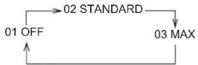
You can reduce (or compress) the difference between the maximum and minimum sound levels for your listening comfort during playback of a disc. There are three settings available, each having a different level of compression. If you select the "MAX" setting, the dynamic range control lowers the maximum sound level while raising the minimum sound level. This makes the audio sounds gentler to your ears.
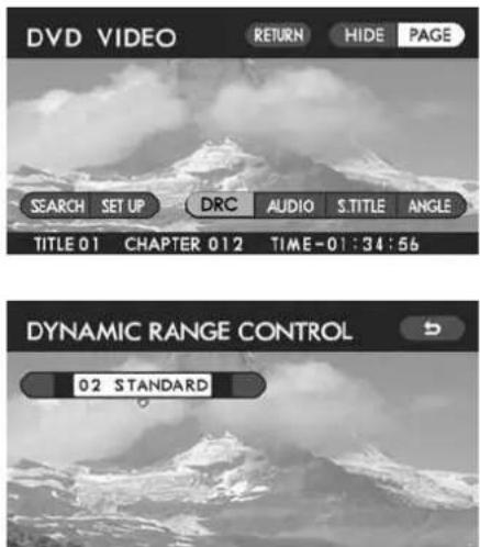
Highlight the "DRC" switch on the screen with the remote control joystick, then press the "ENTER" button. The display will switch to the dynamic range control selection screen.
Click the "end of the remote control joystick. Each time it is clicked, the setting changes in the following sequence:
flowchart
graph TD
    A["01 OFF"] --> B["02 STANDARD"]
    B --> C["03 MAX"]
    C --> A
NOTE
The default setting of the dynamic range control is "02 STANDARD".
With the desired setting selected, press the "ENTER" button.
To revert to the original video screen, highlight the "→" switch with the joystick, and then press the "ENTER" button.
Playing Video CDs
■ Starting playback
With the ignition switch in the "ACC" or "ON" position, insert the CD into the disc slot of the DVD player, with the label side facing up. The player automatically starts playing the disc.
If a disc is already in the player, press the remote control "DVD·CD" button on your remote control to start playback.
■ Stopping playback
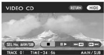
Method using screen and remote control:
Highlight the "■" switch on the screen with the remote control joystick, then press the "ENTER" button.
Method using remote control alone:
Press the remote control "STOP (■) button.
■ Pausing
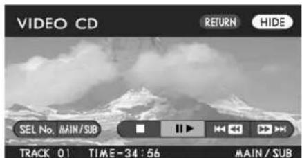
Method using screen and remote control:
Highlight the "I" switch on the screen with the remote control joystick, then press the "ENTER" button.
Method using remote control alone:
Press the remote control "PAUSE • PLAY (") button.
To restart playback, perform either of the above operations again.
■ Fast-forwarding
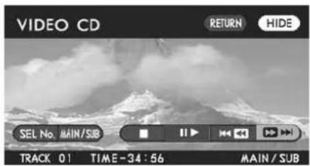
Method using screen and remote control:
Highlight the "▶ switch on the screen with the remote control joystick, then press the "ENTER" button continuously until reaching the desired scene.
Method using remote control alone:
Press the remote control "TRACK (▶)" button continuously until reaching the desired scene.
When you perform either of the above operations while the player is in pause mode, the disc advances slowly.
Fast-reversing
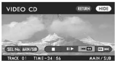
Method using screen and remote control:
Highlight the "K" switch on the screen with the remote control joystick, then press the "ENTER" button continuously until reaching the desired scene.
Method using remote control alone:
Press the remote control "TRACK (")" button continuously until reaching the desired scene.
■ Skipping tracks forward
The data recorded on video CDs is divided into fragments called "tracks". These tracks are given specific numbers, which are indicated in the guide accompanying each disc. You can advance the disc skipping a track or tracks as follows:
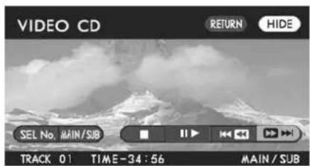
Method using screen and remote control:
Highlight the “▶▶▶” switch on the screen with the remote control joystick, then briefly press the “ENTER” button. The disc skips the current track and advances to the beginning of the next track. Repeat this operation as many times as necessary to reach the desired track.
Method using remote control alone:
Briefly press the remote control "TRACK (▶) button. Refer to the above for the subsequent process and operation.
NOTE (Ver 2.0 video CD only)
Track skipping is not possible with some Ver 2.0 video CDs. For information on track skipping of each Ver 2.0 video CD, refer to the guide accompanying it.
■ Skipping tracks backward
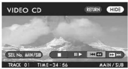
Method using screen and remote control:
Highlight the "K" switch on the screen with the remote control joystick, then briefly press the "ENTER" button. The disc reverses to the beginning of the current track. If you briefly press the button again, the disc reverses to the beginning of the preceding track. Repeat this operation as many times as necessary to reach the desired track.
Method using remote control alone:
Briefly press the remote control "TRACK (■) button. Refer to the above for the subsequent process and operation.
NOTE (Ver 2.0 video CD only)
Track skipping is not possible with some Ver 2.0 video CDs. For information on track skipping of each Ver 2.0 video CD, refer to the guide accompanying it.
■ Skipping to a predetermined screen (Ver 2.0 video CD only)
You can start playing a disc beginning with a registered predetermined screen. Some discs may not be compatible with this function. For the predetermined screen of each disc, refer to the guide accompanying it.
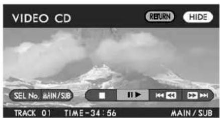
Method using screen and remote control:
Highlight the "RETURN" switch on the screen with the remote control joystick, then press the "ENTER" button. Playback will start at the predetermined screen.
Method using remote control only:
Press the "RETURN" button on the remote control. Playback will start at the predetermined screen.
■ Sound channel (MAIN/SUB) selection
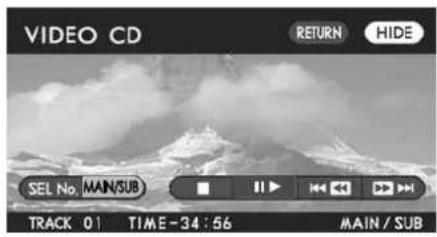
Highlight the "AUDIO" switch on the screen with the remote control joystick, then press the "ENTER" button once or as many times as necessary to select the desired sound channel. Each time you press the "ENTER" button, the sound channel will change in the following sequence:
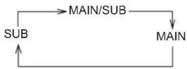
flowchart
graph TD
    A["SUB"] --> B["MAIN/SUB"]
    B --> C["MAIN"]
    C --> A
NOTE
The default sound channel setting is "MAIN/SUB".
Playing Music CDs
■ Starting playback
With the ignition switch in the "ACC" or "ON" position, insert the CD into the disc slot of the DVD player, with the label surface facing up. The player automatically starts playing the disc.
If a disc is already in the player, press the remote control "DVD • CD" button on your remote control to start playback.
■ Stopping playback
To stop playback of a music CD, perform the following:
- Press the remote control "OFF" button.
- Press the "Eject (▲)" button on the DVD player.
■ Fast-forwarding
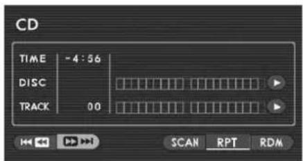
Method using screen and remote control:
Highlight the "▶ switch on the screen with the remote control joystick, then press the "ENTER" button continuously.
Method using remote control alone:
Press the remote control "TRACK (▶) button continuously.
Fast-reversing
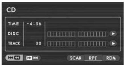
Method using screen and remote control:
Highlight the "K" switch on the screen with the remote control joystick, then press the "ENTER" button continuously.
Method using remote control alone:
Press the remote control "TRACK (1)" button continuously.
■ Skipping tracks forward
You can advance the disc skipping one or more tracks as follows:
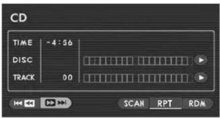
Method using screen and remote control:
Highlight the “▶▶▶” switch on the screen with the remote control joystick, then briefly press the “ENTER” button. The disc skips the current track and advances to the beginning of the next track. Repeat this operation as many times as necessary to reach the desired track.
Method using remote control alone:
Briefly press the remote control "TRACK (▶) button. Refer to the above for the subsequent process and operation.
■ Skipping tracks backward
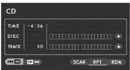
Method using screen and remote control:
Highlight the "KKK" switch on the screen with the remote control joystick, then press the "ENTER" button. The disc reverses to the beginning of the current track. If you briefly press the button again, the disc reverses to the beginning of the preceding track. Repeat this operation as many times as necessary to reach the desired track.
Method using remote control alone:
Briefly press the remote control "TRACK (") button. Refer to the above for the subsequent process and operation.
■ Repeat playback
If you want to listen to the currently playing track again, perform the following:
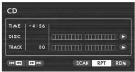
Highlight the "RTP" switch on the screen with the remote control joystick, then press the "ENTER" button.
The repeat-play mode will be cancelled if you press the "ENTER" button again.
■ Random playback
You can play all of the tracks on the disc currently in the player in a random order by doing the following:
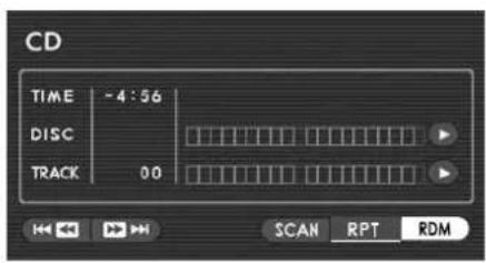
Highlight the "RDM" switch on the screen with the remote control joystick, then press the "ENTER" button.
The random playback will be cancelled if you press the "ENTER" button again.
Scan
The scan mode lets you listen to the first 10 seconds of each track on the disc in succession. Do the following to scan-play the disc:
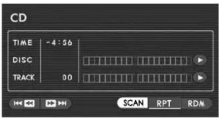
Highlight the "SCAN" switch on the screen with the remote control joystick, then press the "ENTER" button.
The scan mode will be cancelled if you press the "ENTER" button again.
Initial Settings
We recommend that you make these initial settings before enjoying DVD video discs with your Rear Seat Entertainment System in order to eliminate the inconvenience of making selections and settings each time you play a disc.
• DVD language (ENGLISH)
• Audio language (ENGLISH)
- Subtitle language (ENGLISH)
• Angle mark (ON)
• Viewer restriction level (8)
- Password
NOTE
- The settings shown in ( ) above are default settings made before shipment from the factory. When you highlight the “DEFAULT” switch on the “SETUP MENU” screen with the remote control joystick and then press the “ENTER” button, all settings return to the default settings.
- Some discs already contain audio language and other settings. These settings take priority over your settings.
- If the vehicle's power supply is interrupted due to, for example, disconnection of the battery or a blown fuse, all your settings will be cancelled and the system will revert to the factory settings. If this happens, make your settings again.
Perform these settings from the SETUP MENU screen on the display. To access the SETUP MENU screen, do the following:
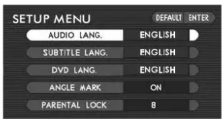
Method using screen and remote control:
Highlight the "SET UP" switch on the screen with the remote control joystick, then press the "ENTER" button. The display will switch to the SETUP MENU screen.
Method using remote control alone:
Press the remote control "SETUP" button.
Setting DVD/Audio/Subtitle Language
The following languages are available for setting:
- ENGLISH
- FRENCH
- SPANISH
• GERMAN - ITALIAN
• DUTCH - JAPANESE
- OTHERS
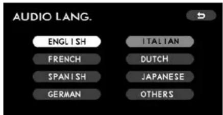
* This figure shows the screen for setting the audio language.
On the SETUP MENU screen, highlight a language mode (DVD, Audio, or Subtitle mode) for which you wish to set a language using the remote control joystick and then press the "ENTER" button. Once the language mode has been selected, you can now set the desired language by highlighting it with the joystick and then pressing the "ENTER" button. The switch color of the set language changes from white to gray.
Do the same for the remaining language modes.
To revert to the SETUP MENU screen, highlight the “” switch with the joystick, and then press the “ENTER” button.
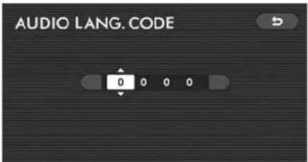
* This figure shows the screen for setting the audio language.
If you wish to set a language not included in the list of languages that appears on the SETUP MENU screen, highlight "OTHERS" in the second step above and enter the code of the desired language (refer to the language code list on Page 55) using the joystick. After entering the code, press the "ENTER" button.
To revert to the SETUP MENU screen, highlight the "switch with the joystick, and then press the "ENTER" button.
Setting the Angle Mark Display
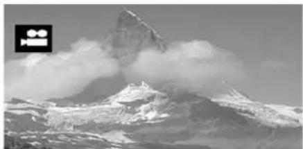
natural_image
Snow-covered mountain peak with cloud formations and a camera icon in the corner (no text or symbols)Angle mark
This setting allows you to decide whether or not the angle mark is to be displayed on the screen. If you select "ON" in the procedure below, the angle mark is displayed at the top left portion of the screen whenever a multi-angle recorded scene is encountered during playback. Refer to Page 34 for information on the multi-angle recorded scenes.
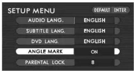
On the SETUP MENU screen, highlight "ANGLE MARK" with the remote control joystick, followed by pressing the "ENTER" button. Then, the angle mark display switches between "ON" and "OFF" each time the "ENTER" button is pressed. Select either "ON" or "OFF" as desired.
NOTE
- Image angle selection is not possible for DVD video discs that do not contain multi-angle recorded scenes.
- You can enjoy multi-angle recorded scenes by changing their angle even when "OFF" is set for the angle mark display.
Setting the Viewer Restriction Level
If you make this setting, certain scenes contained in the DVD video disc in the player are prevented from appearing on the screen. The highest restriction level is 1 and the lowest is 8.
NOTE
This setting is not effective for discs without a pre-programmed viewer restriction feature.
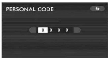
With an appropriate DVD video disc loaded in the player, access the SETUP MENU screen. Highlight "PARENTAL LOCK" with the remote control joystick, then press the "ENTER" button. The display will change to the "PERSONAL CODE" screen.
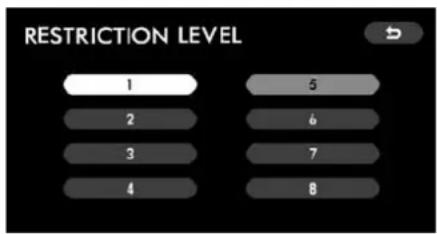
Enter your four-digit password using the joystick, then press the "ENTER" button. The display will change to the "RESTRICTION LEVEL" screen.
Select a restriction level number (1 - 8) with the joystick, then press the "ENTER" button. The switch color of the set number changes from white to gray.
To return to the SETUP MENU screen, highlight the “” switch with the joystick, and then press the “ENTER” button.
NOTE
- No default has been set for the password. The "PERSONAL CODE" screen will show "-"Register your password as instructed in "Password registration" below.
- Entry of a wrong password results in an "INCORRECT CODE" message. If this message appears, you cannot continue the viewer restriction setting operation unless you re-enter the correct password. (Refer to Page 54.)
- If you forget your password, return the system to the state before registering the password. The method for doing this is described in NOTE of "Password registration" below. Next, register a new password.
■ Password registration
Use this method to register your password, which is necessary when setting the viewer restriction level.
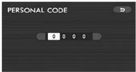
With a DVD video disc loaded in the player, access the SETUP MENU screen. Highlight the "PARENTAL LOCK" with the remote control joystick, then press the "ENTER" button. The display will change to the "PERSONAL CODE" screen.
Enter a numerical four-digit password using the joystick, then press the "ENTER" button.
NOTE
If necessary, you can return the system to the state before registration of the password by doing the following:
On the "PERSONAL CODE" screen, highlight the first digit position with the joystick, and then click the "◀" mark end of the joystick 10 times. The screen will show "-", indicating that no password has been set.
Connecting External Devices to Your Rear Seat Entertainment System
You can enjoy TV games from a home-use TV game machine or video programs from a video tape player with the Rear Seat Entertainment System if such an external device is connected to one of the external device jacks of the system. For further details, refer to the instruction manual provided by the manufacturer of each external device.
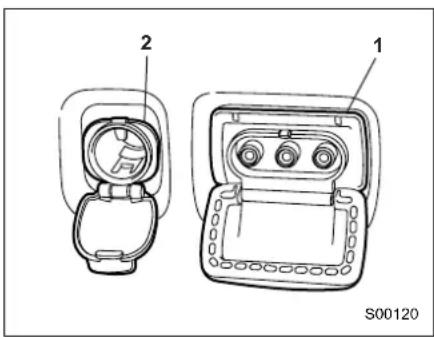
1) External device jacks
2) Accessory power outlet
Before you can use an external source device connected to the system, push the remote control's "VIDEO" button.
The external device jacks are located on the left side wall behind the second-row seat. Open the cover to use the jacks.
There are three jacks individually marked with different colors to identify their uses as follows:
Yellow: external video devices
Red: external audio devices
White: external audio devices
Of the three accessory power outlets provided in your vehicle, the one located next to the external device jacks can be used to supply power to an external device. When using the power outlet, be sure to read the “Accessory power outlets” section in chapter 6 of the Owner's Manual.
CAUTION
- Keep the cover closed when the external device jacks are not in use.
- Be sure to connect only appropriate plugs that fit the jacks. Doing otherwise could cause electrical failures or short circuits in the system.
- Do not allow spilled drinks or other foreign matter to get into the external device jacks. That could cause failure of the system.
- Rear-seat passengers must be careful not to hit connected plugs with their body or anything else; failure of the system could result.
Adjusting Display Conditions and Selecting Display Mode
In addition to the function that allows you to adjust the display color and other esthetic conditions, the Rear Seat Entertainment System has a function that enables you to select the display mode (normal and wide screens) according to your preference. Use the following methods for the adjustment and selection.
Display Condition Adjustment
You can adjust the display conditions with respect to the following items:
- Brightness
- Contrast
- Tone (gradation)
• Color (balance)
NOTE
- Tone and color adjustments are not possible when a music CD is loaded in the player.
- This setting is defaulted to medium within the adjustable range for each of the above adjustment items.
■ Adjusting method
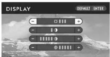
* This figure shows the screen when a DVD video disc or video CD is loaded in the player.
Press the remote control "DISPLAY" button. The display condition adjustment screen will appear.
Highlight the desired adjustment item with the joystick, and then click either the “◀” or “▶” end of the joystick referring to the table below. (Clicking the “ ” end results in “−” direction adjustments and clicking the “▶” end results in “+” direction adjustments.)
Set each adjustment by selecting the "ENTER" switch on the screen or pressing the remote control "ENTER" button.
NOTE
Select the "DEFAULT" switch to revert to a default setting.
| Item “+” direction (“”) “−” direction (“”) | |
| BRIGHTNESS Brighter Darker | |
| CONTRAST Stronger contrast Weaker contrast | |
| TONE Steeper tone gradation Gentler tone gradation | |
| COLOR Stronger green colors Stronger red colors |
Display Mode Selection
The following three display modes are available for your selection:
- Normal
- Wide 1
- Wide 2
NOTE
- You cannot change the display mode when a music CD is loaded in the player.
- The default display mode setting is "Wide 1".
■ Selecting method
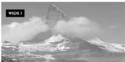
natural_image
Snow-covered mountain peak with cloud formations, labeled 'WIDE 1' in top-left corner (no other text or symbols)* This figure shows a screen image when the "WIDE 1" mode is selected.
Each time you press the remote control "DISPLAY MODE" button, the mode changes in the following sequence:
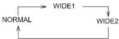
flowchart
graph TD
    A["NORMAL"] --> B["WIDE1"]
    B --> C["WIDE2"]
    C --> A
Release the "DISPLAY MODE" button; 6 seconds later, a full screen will be displayed in the selected mode.
Error Messages
The Rear Seat Entertainment System displays one of the following messages whenever it detects the relevant error condition. If an error message is displayed, take the appropriate action that is indicated on this page.
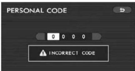
Cause: A wrong password (personal code) has been entered.
Remedy: Enter the correct password (refer to Page 49).
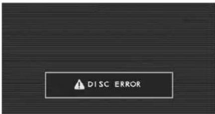
Cause:
• The disc has been inserted with the la-
bel side down.
- The disc is dirty. - The disc is incompatible with the system.
Remedy: Check the inserted disc for any of the above causes. Correctly insert, clean or change the disc as necessary.
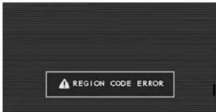
Cause: The inserted disc is of an inappropriate region code.
Remedy: Use only a disc marked "ALL" or "1".
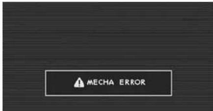
Cause: Operational obstruction or other
mechanical fault has occurred during disc insertion or ejection.
Remedy: Have the system inspected by your SUBARU dealer.
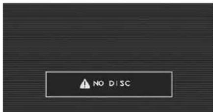
Cause: Remote control "DVD • CD" button has been pressed when there is no disc in the player.
Remedy: Load a disc into the player.
Language/Code List
| Language Code | |
| Afar 0101 | |
| Abkhazian 0102 | |
| Afrikaans 0106 | |
| Amharic 0113 | |
| Arabic 0118 | |
| Assamese 0119 | |
| Aymara 0125 | |
| Azerbaijani 0126 | |
| Bashkir 0201 | |
| Byelorussian 0205 | |
| Bulgarian 0207 | |
| Bihari 0208 | |
| Bislama 0209 | |
| Bengali; Bangla 0214 | |
| Tibetan 0215 | |
| Breton 0218 | |
| Catalan 0301 | |
| Corsican | 0315 |
| Language Code | |
| Czech 0319 | |
| Welsh | 0325 |
| Danish | 0401 |
| German | 0405 |
| Bhutani | 0426 |
| Greek | 0512 |
| English | 0514 |
| Esperanto | 0515 |
| Spanish | 0519 |
| Estonian | 0520 |
| Basque | 0521 |
| Persian | 0601 |
| Finnish | 0609 |
| Fiji | 0610 |
| Faroese 0615 | |
| French | 0618 |
| Frisian | 0625 |
| Irish | 0701 |
| Language Code | |
| Scots Gaelic | 0704 |
| Galician | 0712 |
| Guarani 0714 | |
| Gujarati | 0721 |
| Hausa | 0801 |
| Hindi | 0809 |
| Croatian | 0818 |
| Hungarian | 0821 |
| Armenian | 0825 |
| Interlingua 0901 | |
| Indonesian (formerly in) | 0914 |
| Interlingua 0905 | |
| Inupiak | 0911 |
| Icelandic | 0919 |
| Italian | 0920 |
| Inuktitut | 0921 |
| iw Hebrew (formerly iw) | 0923 |
| Japanese | 1001 |
| Language | Code |
| Yiddish (formerly ji) 1009 | |
| Javanese 1023 | |
| Georgian 1101 | |
| Kazakh 1111 | |
| Greenlandic 1112 | |
| Cambodian 1113 | |
| Kannada 1114 | |
| Korean 1115 | |
| Kashmiri 1119 | |
| Kurdish 1121 | |
| Kirghiz 1125 | |
| Latin 1201 | |
| Lingala 1214 | |
| Laothian 1215 | |
| Lithuanian 1220 | |
| Latvian, Lettish 1222 | |
| Malagasy 1307 | |
| Maori | 1309 |
| Language | Code |
| Macedonian | 1311 |
| Malayalam | 1312 |
| Mongolian 1314 | |
| Moldavian | 1315 |
| Marathi 1318 | |
| Malay | 1319 |
| Maltese | 1320 |
| Burmese 1325 | |
| Nauru | 1401 |
| Nepali | 1405 |
| Dutch | 1412 |
| Norwegian | 1415 |
| Occitan 1503 | |
| (Afan) Oromo | 1513 |
| Oriya | 1518 |
| Punjabi 1601 | |
| Polish | 1612 |
| Pashto, Pushto | 1619 |
| Language | Code |
| Portuguese 1620 | |
| Quechua | 1721 |
| Rhaeto-Romance | 1813 |
| Kirundi | 1814 |
| Romanian | 1815 |
| Russian | 1821 |
| Kinyarwanda | 1823 |
| Sanskrit | 1901 |
| Sindhi | 1904 |
| Sangho | 1907 |
| Serbo-Croatian | 1908 |
| Sinhalese | 1909 |
| Slovak | 1911 |
| Slovenian | 1912 |
| Samoan | 1913 |
| Shona | 1914 |
| Somali 1915 | |
| Albanian 1917 | |
| Serbian 1918 | |
| Siswati 1919 | |
| Sesotho 1920 | |
| Sundanese 1921 | |
| Swedish 1922 | |
| Swahili 1923 | |
| Tamil 2001 | |
| Telugu 2005 | |
| Tajik 2007 | |
| Thai 2008 | |
| Tigrinya 2009 | |
| Turkmen 2011 | |
| Tagalog 2012 | |
| Setswana 2014 | |
| Tonga 2015 | |
| Turkish 2018 | |
| Tsonga 2019 | |
| Tatar | 2020 |
| Language | Code |
| Twi | 2023 |
| Uighur | 2107 |
| Ukrainian | 2111 |
| Urdu | 2118 |
| Uzbek 2126 | |
| Vietnamese | 2209 |
| Volapuk 2215 | |
| Wol'of' | 2315 |
| Xhosa 2408 | |
| Yoruba | 2515 |
| Zhuang | 2601 |
| Chinese 2608 | |
| Zulu 2621 |
natural_image
Empty grid with dashed lines and a solid black line at the top (no text or symbols)Foreword
CongratulationschoosingaSUBARUvehicle.ThisOwner's ManualhasalltheinformationnecessarytokeepyourSUBARUin excellentconditionandtoproperlymaintaintheemissioncontrol systemforminimizingemissionpollutants.Weurgeyoutoread thismanualcarefullysothatyoumayunderstandyourvehicleand itsoperation.ForinformationnotfoundinthisOwner'sManual, suchasdetailsconcerningrepairsoradjustments,pleasecontact theSUBARUdealerfromwhomyoupurchasedyourSUBARUor thenearestSUBARUdealer.
Theinformation, specifications and illustrations found in this manual are those ineffect at the time of printing. FUJIHEAVY INDUSTRIESLTD. reservest heright to changes specifications and designs at any timewithout prior notice and without incurring any obligation to make these same similar changes on vehicles previously sold. This Owner's Manual appliesto all models and covers all equipment, including factory installed options. Some explanations, therefore may before equipment not installed in your vehicle.
Pleaseleavethismanualinthevehicleatthetimeofresale.The nextownerwillneedtheinformationfoundherein.
All SUBARU vehicles distributed by SubaruofAmerica, Inc. and sold at retail by unauthorized SUBARU dealer in the United States comewith the following warranties.
- SUBARULimitedWarranty
●EmissionControlSystemsWarranty
●EmissionsPerformanceWarranty
Allwarrantyinformation,includingdetails ofcoverageandexclusions,isinthe "Warranty and Maintenance Booklet". Pleasereadthesewarrantiescarefully.
WarrantiesforCanada
All SUBARU vehicles distributed by SubaruCanada, Inc. and sold at retail by an authorized SUBARU dealer in Canada comewith the following warranties.
- SUBARULimitedWarranty
●Anti-CorrosionWarranty
●EmissionControlWarranty
Allwarrantyinformation,includingdetails ofcoverageandexclusions,isinthe "WarrantyandServiceBooklet".Please readthesewarrantiescarefully.
CAUTION
- Ifyourvehicleisequippedwitha navigationsystemand/orRear SeatEntertainmentSystem,the displayscontainmercury.Therefore,thedisplaysofthenavigationsystemand/orRearSeat EntertainmentSystemmustbe removedbeforevehicledisposal. Oncethedisplayshavebeen removed, please reuse, recycle ordisposeofthemashazardous waste.
- If your vehicle is equipped with High Intensity Discharge (HID) headlights, the HID headlights contain mercury. Therefore, it is necessary to remove HID headlights before vehicled disposal. Onceremoved, pleasereuse, recycleord dispose of the HID headlights ashazardous waste.
HowtousethisOwner's Manual
■UsingyourOwner'sManual
Before you operate your vehicle, carefully read this manual. Top protect yourself and extend the service life of your vehicle, follow the instructions in this manual. Failure to observ these instructions may result in serious injury and damage to your vehicle.
Thismanualiscomposedoffourteen chapters. Eachchapterbeginswithabrief tableofcontents,soyoucanusuallytellat aglanceifthatchaptercontainsthe informationyouwant.
Chapter1: Seat, seatbelt and SRS airbags
Thischapterinformsyouhowtousethe seatandseatbeltandcontainsprecautionsfortheSRSairbags.
Chapter2:Keysanddoors
Thischapterinformsyouhowtooperate thekeys, locksandwindows.
Chapter3: Instrumentsandcontrols
This chapter informs you about the operation of instrument panel indicators and how to use the instruments and other switches.
Chapter4:Climatecontrol
Thischapterinformsyouhowtooperate theclimatecontrol.
Chapter5:Audio
Thischapterinformsyouhowtooperate youraudiosystem.
Chapter6: Interiorequipment
Thischapterinformsyouhowtooperate interiorequipment.
Chapter7: Starting and operating
Thischapterinformsyouhowtostartand operateyourSUBARU.
Chapter8:Drivingtips
Thischapterinformsyouhowtodriveyour SUBARUinvariousconditionsandex- plainssomesafetytipsondriving.
Chapter9: Incaseofemergency
Thischapterinformsyouwhattodoifyou haveaproblemwhiledriving,suchasa flattireorengineoverheating.
Chapter10: Appearancecare
Thischapterinformsyouhowtokeepyour SUBARUlookinggood.
Chapter11: Maintenance and service
Thischapterinformsyouwhenyouneed totakeyourSUBARUtothedealerfor scheduledmaintenanceandinformsyou howtokeepyourSUBARUrunning properly.
Chapter12:Specifications
ThischapterinformsyouaboutthedimensionsandcapacitiesofyourSUBARU.
Chapter13: Consumerinformation and Reportingsafetydefects
ThischapterinformsyouaboutTire information,Uniformtirequalitygrading standardsandReportingsafetydefects.
Chapter14:Index
Thisisanalphabeticallistingofallthat'sin thismanual.Youcanuseittoquicklyfind somethingyouwanttoread.
■ Safetywarnings
YouwillfindanumberofWARNINGS, CAUTIONsandNOTEsinthismanual.
Thesesafetywarningsalertyoutopotentialhazardsthatcouldresultinjurytoyouorothers.
Pleasereadthesesafetywarningsaswell asallotherportionsofthismanualcarefullyinordertogainabetterunderstandingofhowtouseyourSUBARUvehicle safely.

WARNING
AWARNINGindicatesasituationin whichseriousinjuryordeathcould resultifthewarningisignored.

CAUTION
ACAUTION indicates asituation in which injury or damage to your vehicle, or both, could result if the caution is ignored.
NOTE
ANOTEgivesinformationorsuggestionshowtomakebetteruseofyour vehicle.

Safetysymbol

natural_image
Prohibition symbol with a circle and diagonal line, commonly used to indicate prohibition or no use.000013
Youwillfindacirclewithaslashthroughit inthismanual. Thissymbolmeans "Do not", "Do not do this", or "Do not let this happen", depending upon the context.
Vehiclesymbols
Therearesomeofthesymbolsyoumay seeonyourvehicle.
Forwarningandindicatorlights, refer to "Warningandindicatorlights" 19.
| MarkName | |
| WARNING | |
| CAUTION | |
| Passengers'windowslock | |
| Fuel | |
| Frontfoglights | |
| Parkinglights | |
| Hazardwarningflasher | |
| Seatheater | |
| Childrestraintloweran-chorages | |


MarkName
Childrestrainttoptetheran-
chorages


DDE Parkinglights, taillights, licenseplatelights and instrument panel illumination
| MarkName | |
 | Headlights |
 | Turnsignal |
 | Illuminationbrightness |
 | Enginehood |
 | Fanspeed |
 | Instrumentpaneloutlets |
 | Instrumentpaneloutletsandfootoutlets |
 | Footoutlets |
 | Windshielddefrosterandfoot outlets |
 | Windshielddefroster |
 | Rearwindowdefogger/Out-sidemirrordefogger |
-CONTINUED-
| MarkName | |
 | Airrecirculation |
 | Outsideair |
 | Engineoil |
| [604W] | Washer |
| [7CXS] | Doorlock(transmitter) |
| [7070] | Doorunlock(transmitter) |
| [02X3] | Reargate(transmitter) |
 | Powerfoldingmirror |
Safetyprecautionswhen driving
■ SeatbeltandSRSairbag

WARNING
- Allpersonsinthevehicleshould fastentheirseatbeltsBEFORE thevehiclestartstomove. Otherwise, thepossibilityofserious injurybecomesgreaterinthe eventofasuddenstoporaccident.
- Toobtainmaximumprotectionin the eventofanaccident, the driverandallpassengersinthe vehicleshouldalwayswearseatbeltswhenthevehicleismoving. TheSRS(Supplemental Restraint System)airbagdoesnotdoaway withtheneedtofastenseatbelts. Incombinationwiththeseatbelts,itoffersthebestcombined protectionin case ofa serious accident.
Notwearingaseatbeltincreases thechanceofsevereinjuryor deathinacrashevenwhenthe vehiclehastheSRSairbag.
•The SRSairbagsdeploy with considerable speed and force. Occupants who are out of proper position when the SRSairbag deploys could suffer very serious injuries. Because the SRSairbag needs enough space for deployment, the drivers should always sit upright and well back in the seat as far from the steering wheel as practical while still maintaining full vehicle control and the front passenger should move these at as far back as possible and sit upright and well back in these at.
For instructions and precautions, carefully read the following sections.
- Fortheseatbeltsystem, referto "Seatbelts" 1-16.
- For the SRS airbag system, refer to "*SRSairbag(SupplementalRestraint Systemairbag)": 1-45.
Childsafety
WARNING
●Neverholdachildonyourlapor inyourarmswhilethevehicleis moving. Thepassengercannot protectthechildfrominjuryina collision, because thechildwill becaught between the passenger and objects inside the vehicle.
- Whileridinginthevehicle, infantsandsmallchildrenshould alwaysbeplacedinoneofthe rearseatingpositionsrecommendedinthisOwner'sManual inaninfantorchildrestraint systemwhichisappropriatefor the child's age,height and weight.Ifachildistoobigfora childrestraintsystem,thechild shouldsitinaREARseatandbe restrainedusingtheseatbelts. Accordingtoaccidentstatistics, childrenaresaferwhenproperly restrainedintherearseating positionsthaninthefrontseatingpositions.Neverallowachild tostanduporkneelontheseat.
●Putchildrenaged12andunderin aREARseatproperlyrestrained
atalltimesinachildrestraint deviceorinaseatbelt.TheSRS airbagdeployswithconsiderable speedandforceandcaninjureorevenkillchildren,especiallyif theyare12yearsofageand underandarenotrestrainedor improperlyrestrained.Because children are lighter and weaker thanadults, theirrisk ofbeing injuredfromdeploymentisgreat-er.
●NEVERINSTALL AREARWARD FACINGCHILDSAFETYSEATIN THEFRONTSEAT.DOINGSO RISKSSERIOUSINJURYOR DEATHTOTHECHILDBYPLACING THECHILD'SHEAD TOO CLOSETOTHESRSAIRBAG.
●Alwaysusethechildsafetylocks wheneverachildridesinthe rear.Seriousinjurycouldresult ifachildaccidentallyopened the doorandfellout.Referto"Child safetylocks"2-21.
●Alwayslockthepassenger'swindowsusingthelockswitchwhenchildrenareridinginthevehicle. Failuretofollowthisprocedure couldresultininjurytoachild operatingthepowerwindow.Referto"Powerwindows" 2-21.
●Neverleaveunattendedchildren inthevehicle. They could accidentally injurethemselves or othersthroughinadvertentoperation of the vehicle. Also, on hotorsunnydays, temperature inaclosedvehicle could quickly become highenoughto cause severeorpossiblyfatalinjuries to them.
For instructions and precautions, carefully read the following sections.
- Fortheseatbeltsystem, referto "Seatbelts" 1-16.
- Forthechildrestraintsystem,referto "Childrestraintsystems" 1-31.
- For the SRS airbag system, refer to "*SRSairbag(SupplementalRestraint Systemairbag)"\~1-45.
■Engineexhaustgas(carbon monoxide)
WARNING
- Neverinhaleengineexhaustgas. Engineexhaustgas contains carbonmonoxide, acolorless and odorless gas which is dangerous, orevenlethal, ifinhaled.
●Alwaysproperlymaintaintheen-
-CONTINUED-
gineexhaustsystemtoprevent engineexhaustgasfromenter- ingthevehicle.
- Neverruntheengineinaclosed space,suchasagarage,except forthebrieftimeneededtodrive thevehicleinoroutofit.
- Avoidremaininginaparked vehicleforalengthytimewhile theengineisrunning.lfthatis unavoidable,thenusetheventilationfantoforcefreshairinto thevehicle.
●Alwayskeepthefrontventilator inletgrillefreefromsnow,leaves orotherobstructionstoensure thattheventilationsystemalwaysworksproperly. - Ifatanytimeyoususpectthat exhaustfumesareenteringthe vehicle, have the problem checkedandcorrectedassoon aspossible.Ifyoumustdrive undertheseconditions,drive onlywithallwindowsfullyopen.
- Keepthereargateclosedwhile driving to prevent exhaust gas fromenteringthevehicle.
■ Drinkinganddriving

WARNING
Drinking and then driving is very dangerous. Alcohol in the bloodstream delays your reaction and impairsyourperception, judgment andattentiveness. If you drive after drinking-evenifyoudrinkjusta little -itwill increasetherisk of being involved in a serious or fatal accident, injuringorkilling yourself, your passengers and others. In addition, if you are injured in the accident, alcohol may increase the severity of that injury. Pleasedon't drink and drive.
Drunkendrivingisoneofthemost frequentcausesofaccidents.Sincealcoholaffectsallpeopledifferently,youmay haveconsumedtoomuchalcoholtodrive safelyevenifthelevelofalcoholinyour bloodisbelowthelegallimit.Thesafest thingyoucandoisneverdrinkanddrive. Howeverif youhave nochoice butto drive,stopdrinkingandsoberupcompletelybeforegettingbehindthewheel.
Drugsanddriving

WARNING
There are some drugs (over the counterandprescription)thatcan delayyourreactiontimeandimpair yourperception.judgmentandattentiveness.Ifyoudriveaftertaking them, it may increase your, your passengers'andotherpersons'risk of being involved in a serious or fatalaccident.
If you are taking any drugs, check with your doctor or pharmacist read the literature that accompanies the medication to determine if the drug you are taking can impair your driving ability. Donot drive after taking any medications that can make you drowsy or otherwise affect your ability to safely operate a motor vehicle. If you have a medical condition that requires you to take drugs, please consult with your doctor.
Neverdrive if you are under the influence of any illicit mind-altering drugs. For your own health and well-being, we urge you not to take illegal drugs in their first place and to seek treatment if you are addicted to those drugs.
■ Drivingwhentiredorsleepy

WARNING
Whenyouaretiredorsleepy,your reactionwillbedelayedandyour perception,judgmentandattentivenesswillbeimpaired.Ifyoudrive whentiredorsleepy,your,your passengers'andotherpersons' chancesofbeinginvolvedina seriousaccidentmayincrease.
Pleasedonotcontinuetodrivebut insteadfindasafeplacetorestifyou aretiredorsleepy.Onlongtrips,you shouldmakeperiodicreststopstorefresh yourselfbeforecontinuingonyourjourney. When possible, you should share the drivingwithothers.
■ Carphone/cellphone and driving

CAUTION
Donotuseacarphone/cellphone whiledriving;itmaydistractyour attentionfromdrivingandcanlead toanaccident.Ifyouuseacar phone/cellphone,pullofftheroad and park in a safe place before usingyourphone.InsomeStates/Provinces,onlyhands-freephones maylegallybeused while driving.
■ Modification of your vehicle

CAUTION
Yourvehicles should not be modified other than with genuine SUBARU parts and accessories. Other types of modifications could affect its performance, safety durability, and may even violate governmental regulations. In addition, damageor performance problems resulting from modification may not be covered under warranties.
■ Drivingvehicle equipped withanavigationsystem

WARNING
Do notallowthe monitor todistract your attention from driving. Also, do not operate the control of the navigation system while driving. The loss of attention to driving could lead to an accident. If you wish to operate the control of the navigation system, first take the vehicle off the road and stop it in safe place.
■ Drivingwithpets
Unrestrainedpetscaninterferewithyour drivinganddistractyourattentionfrom driving.Inacollisionorsuddenstop, unrestrained pets or cages can be thrown aroundinside thevehicleandhurtyour yourpassengers.Besides,thepetscan behurtunderthesesituation.Itisalsofor theirownsafetythatpetsshouldbe properlyrestrainedinyourvehicle.Re-strainapetwithaspecialtraveling harness which can be secured to the rear seatwithaseatbeltoruseapetcarrier which can be secured to the rear seat by routingaseatbeltthroughthecarrier's
-CONTINUED-
handle. Neverrestrainpetsorpetcarriers inthefrontpassenger'sseat. For further information, consult your veterinarian, localanimalprotectionsocietyorpet shop.
Tirepressures

WARNING
Drivingathighspeedswithexcessivelylowtirepressurescancause thetirestodeformseverelyandto rapidlybecomehot.Asharpin-creaseintemperaturecouldcause treadseparation,anddestructionof thetires. Theresultinglossof vehiclecontrolcouldleadtoan accident.
Checkand, if necessary, adjust the pressure of each tire (including the spare) at least once a month and before any long journey.
Checkthetirepressurewhenthetiresare cold.Useapressuregaugetoadjustthe tirepressurestothevaluesshownonthe tireplacard.Fordetailedinformation,refer to"Tiresandwheels" 11-24.
■ Californiaproposition65 warning

WARNING
Engineexhaust, some of its constituents, and certain vehicle components containoremit chemicals known to the State of California cause cancer and birth defect or other reproductive harm. In addition, certain fluids in vehicles and certain components of product wear containoremit chemicals known to the State of California cause cancer and birth defect or other reproductive harm.
■ On-pavementandoff-road driving
This vehicle is classified as a utility vehicle. Utility vehicles have as significantly higher rollover rate than other types of vehicles. Your vehicle has a higher ground clearance and higher center of gravity, making it more likely to rollover than ordinary passengers cars. It also handles and maneuvers differently from other passengers cars. For this reason, please read carefully the following section and follow the instructions and precautions in ordertoprevent serious injury or death duetoloss of control, rollover and other accidents. Referto "On-pavement and off road driving" 8-5.
Tableofcontents
| Seat,seatbeltandSRSairbags | 1 |
| Keysanddoors | 2 |
| Instrumentsandcontrols | 3 |
| Climatecontrol | 4 |
| Audio | 5 |
| Interiorequipment | 6 |
| Startingandoperating | 7 |
| Drivingtips | 8 |
| Incaseofemergency | 9 |
| Appearancecare | 10 |
| Maintenanceandservice | 11 |
| Specifications | 12 |
| ConsumerinformationandReportingsafetydefects | 13 |
| Index | 14 |
Illustratedindex
■ Exterior
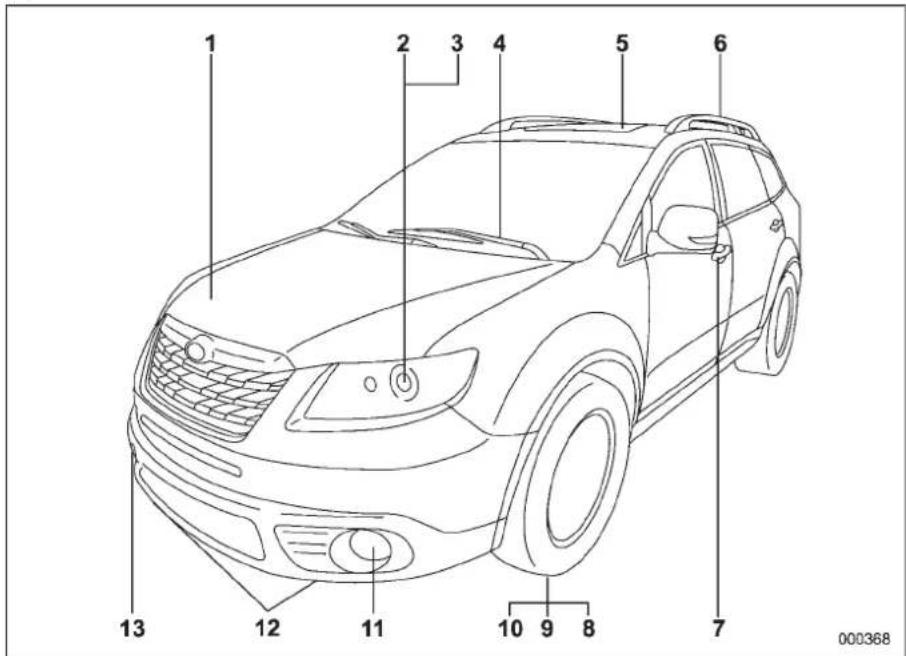
1) Enginehoodlockrelease(page 11-4)
2)Headlightswitch(page3-26)
3)Bulbreplacement(page11-40)
4)Wiperswitch(page3-34)
5)Moonroof(page2-25)
6)Roofrail(ifequipped)(page8-13)
7)Doorlocks(page2-5)
8)Tirepressure(page11-26)
9)Flattires(page9-6)
10) Tirechains(page8-11)
11) Foglightswitch(page3-32)
12)Tie-downhooks(page9-15)
13) Towinghook(page9-14)
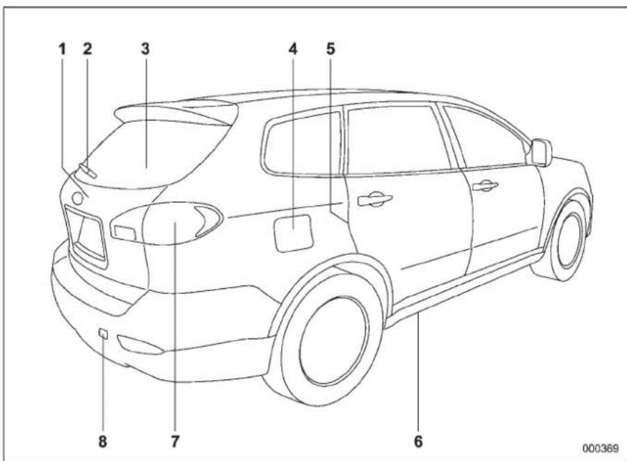
1) Reargate(page2-24)
2)Rearwiperswitch(page3-35)
3) Rearwindowdefoggerbutton (page3-37)
4)Fuelfillerlidandcap(page7-3)
5)Childsafetylocks(page2-21)
6)Tie-downhooks(page9-15)
7)Bulbreplacement(page11-40)
8)Towinghook(page9-14)
-CONTINUED-
Interior
▼Passengercompartmentarea
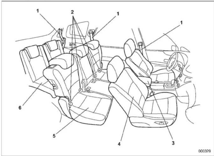
1) Seatbelt(page1-16)
2) Lower anchorages for child restraint system (page 1-38)
3) Centerconsole(page6-6)
4)Frontseat(page1-2)
5)Second-rowseat(page1-7)
6)Third-rowseat(page1-13)
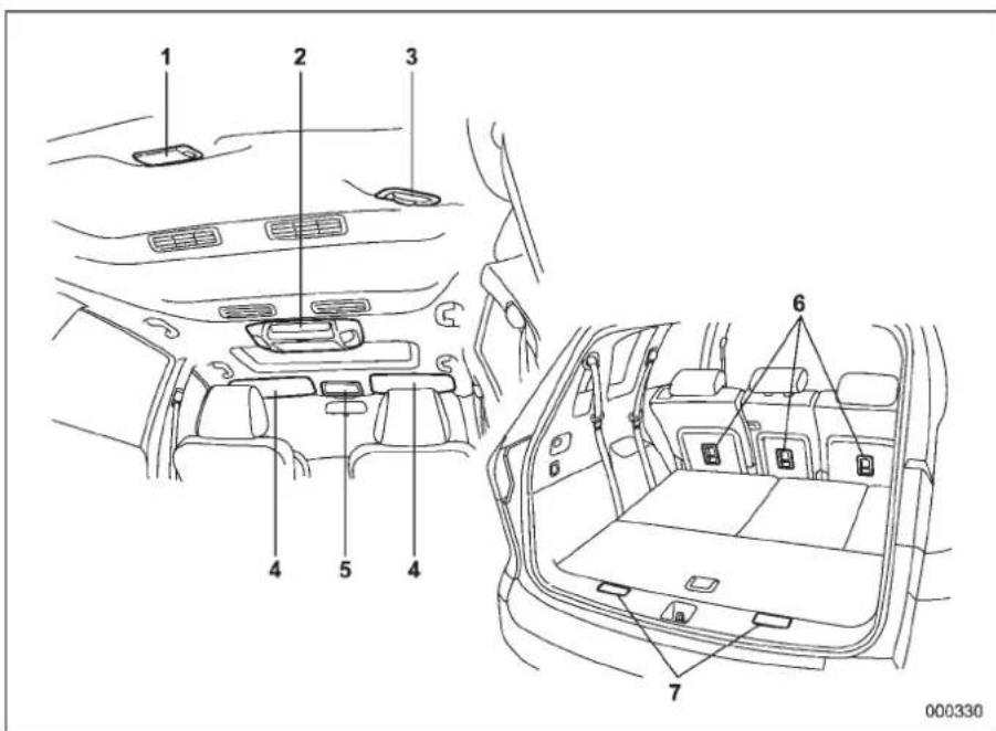
1) Cargoarealight(page6-3)
2)Domelights(page6-2)
3)Rearcenterseatbelt(page1-23)
4)Sunvisors(page6-4)
5)Maplight(page6-3)
6) Toptetheranchorages(rearseat/second-rowseat)(page 1-41)
7) Toptetheranchorages (third-rowseat) (page 1-42)
-CONTINUED-
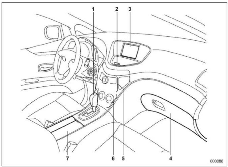
1) Selectlever(page7-13)
2) Hazardwarningflasherswitch (page3-5)
3)Multifunctiondisplay(page3-23)
4)Glovebox(page6-6)
5)Audio(page5-1)
6)Climatecontrol(page4-1)
7) Cupholder(page6-8)
Instrumentpanel
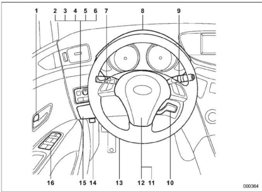
1) Doorlocks(page2-5)
2) Illumination brightness control (page3-28)
3) Remote control mirror switch (page 3-42)
Power folding mirror switch (ifequipped) (page 3-43)
4)Windshieldwiperdeicer(page3-36)
5) TractionControlsystemOFFswitch (page7-27)
6) Headlightbeamleveler(ifequipped) (page3-29)
7)Lightcontrolswitch(page3-26)
8)Combinationmeter(page3-5)
9)Wipercontrollever(page3-33)
10)Cruisecontrol(page7-30)
11)Horn(page3-44)
12)SRSairbag(page1-45)
13)Tiltsteering(page3-44)
14)Hoodlockreleaseknob(page11-4)
15)Fusebox(page11-38)
16)Powerwindows(page2-21)
■Lightcontrolandwipercontrollevers/switches
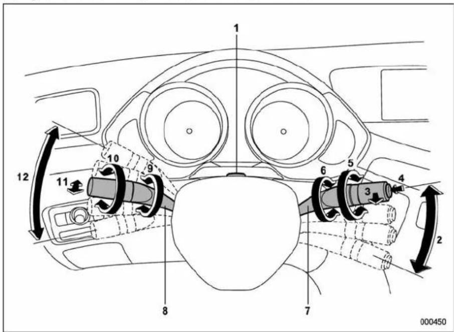
1) Parkinglightswitch(page3-32)
2)Windshieldwiper(page3-33)
3) Mist(page3-34)
4)Windshieldwasher(page3-35)
5) Rearwindowwiperandwasherswitch (page3-35)
6) Wiperintermittenttimecontrolswitch (page3-34)
7)Wipercontrollever(page3-34)
8)Lightcontrolswitch(page3-26)
9)Foglightswitch(page3-32)
10)HeadlightON/OFF(page3-26)
11) Headlightflasher High/Low beam change(page3-27)
12)Turnsignal(page3-28)
■ Combinationmeter
▼U.S.-spec.models
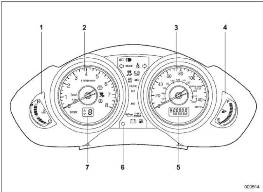
1) Temperature gauge(page3-9)
2)Tachometer(page3-7)
3)Speedometer(page3-6)
4) Fuelgauge(page3-8)
5) Tripmeterandodometer (page3-6/page3-7)
6) TripmeterA/Bselectionandtripmeter resetknob(page3-7)
7) Selectlever/Gearposition indicator (page3-20)
-CONTINUED-
▼ExceptU.S.-spec.models
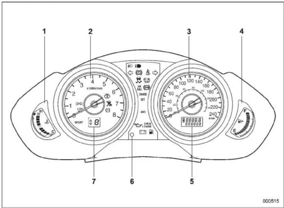
1) Temperature gauge(page3-9)
2)Tachometer(page3-7)
3)Speedometer(page3-6)
4)Fuelgauge(page3-8)
5) Tripmeterandodometer (page3-6/page3-7)
6) TripmeterA/Bselectionandtripmeter resetknob(page3-7)
7) Selectlever/Gearposition indicator (page3-20)
■Warningandindicatorlights
| MarkName | Page | |
| Driver'sseatbeltwarning light | 3-10 | |
| PASS | Frontpassenger'sseat-beltwarninglight | 3-10 |
| AIR BAG | SRSairbagsystem warninglight | 3-11 |
| CHECK ENGINE | CHECKENGINEwarninglight/Malfunctionindicatorlamp | 3-12 |
| Chargewarninglight3-13 | ||
| Oilpressurewarninglight3-13 | ||
| AT OIL TEMP | ATOILTEMPwarning light | 3-13 |
| ABS / ABS | warninglight3-15 | |
| BRAKE / (1) | Brakesystemwarning light | 3-16 |
| Dooropenwarninglight | 3-17 |
| MarkName | Page | |
| Lowfuelwarninglight3-17 | ||
| AWD | AWDwarninglight3-18 | |
| VehicleDynamicsControloperationindicatorlight | 3-18 | |
| VehicleDynamicsControlwarninglight/TractionControlsystemOFFindicatorlight | 3-18 | |
| SECURITY● | Securityindicatorlight3-19 | |
| Turnsignalindicatorlights | 3-20 | |
| Highbeamindicatorlight | 3-20 | |
| Frontfoglightindicatorlight | 3-21 | |
| Headlightindicatorlight | 3-21 | |
| CRUISE | Cruisecontrolindicatorlight | 3-20 |
| MarkName | Page | |
| SET | Cruisecontrolsetindicatorlight | 3-21 |
| Lowtirepressurewarninglight | 3-14 | |
| PassengerairbagONindicatorlight | 3-12 | |
| PassengerairbagOFF indicatorlight | 3-12 | |
| SPORT | SPORTmodeindicator light | 3-20 |
| Windshieldwasherfluid warninglight | 3-18 | |
| R.DIFF TEMP | Reardifferentialoiltemperaturewarninglight | 3-14 |
-CONTINUED-
Cargoarea
▼7-seatermodels
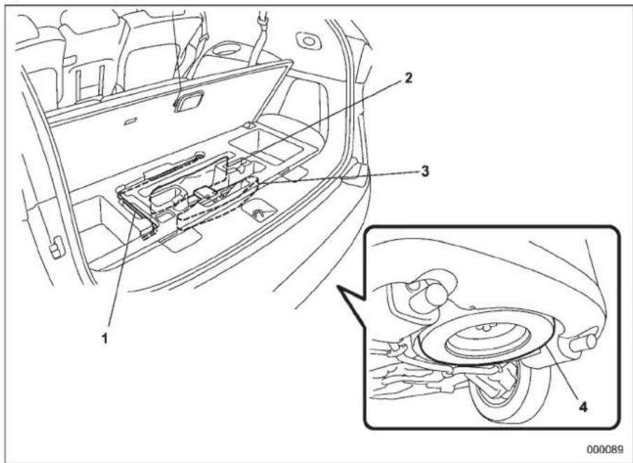
1) Jackhandle(page9-19)
2)Maintenancetools(page9-19)
3)Jack(page9-19)
4)Sparetire(page9-5)
▼5-seatermodels
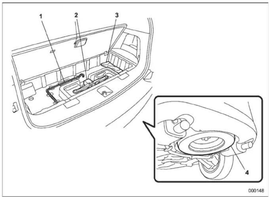
1) Jackhandle(page9-19)
2) Jack(page9-19)
3)Maintenancetools(page9-19)
4) Sparetire(page9-5)
Functionsettings
A SUBARU dealer can change the settings of the functions shown in the following table to meet your personal requirements. Contact the nearest SUBARU dealer for details. If your vehicle is equipped with the genuine SUBARU navigation system, the settings for some of these functions can be changed using the navigation monitor. For details, please refer to the Owner's Manual supplement for the navigation system.
| ItemFunctionPossiblesettings | DefaultsettingPage | |||
| AlarmsystemAlarmsystemOperation | Operation/Non-operationOperation2-16 | |||
| Monitoring start delay time (after closure of doors) | 0 second/30 seconds | 30 seconds | 2-17 | |
| Impactsensoroperation(onlymodelswithshock sensors(dealeroption)) | Operation/Non-operationNon-operation | 2-20 | ||
| Passivearming | Operation/Non-operationNon-operation | 2-19 | ||
| Dome light/map lights illumination | ON/OFF | OFF | 2-16 | |
| Remotekeylessentrysystem | Hazardwarningflasher | Operation/Non-operationOperation2-8 | ||
| Audiblesignal | Operation/Non-operationOperation2-11 | |||
| Key lock-in prevention | Key lock-in prevention | Operation/Non-operation | Operation | 2-7 |
| Remoteenginestartsystem (dealeroption) | Hornchirpconfirmation | ON/OFF | ON | 7-10 |
| Rear window defogger | Rear window defogger | Operation for 15 minutes/Continuousoperation | Operationfor15minutes | 3-37 |
| Windshield wiper deicer | Windshield wiper deicer | Operation for 15 minutes/Continuousoperation | Operationfor15minutes | 3-36 |
| Maplights/Domelight | Operationofmaplights/domelightOFFdelay timer | OFF/Short/Normal/Long | Normal | 6-2/6-3 |
| Map lights | Illumination in conjunction with a door open | Operation/Non-operation | Operation(Illumination-ON) | 6-3 |
| Batterydrainageprevention function | Batterydrainagepreventionfunction | Operation/Non-operationOperation2-6 | ||
| SeatbeltwarningSoundsachim | newhiledrivingOperation/Non-operationOperation1-18 | |||
| -1.5 | -1.5 | -1.5 | -1.5 |
Seat, seatbelt and SRS airbags
Frontseats....1-2
Powerseat....1-3
Memory function (driver's seat – if equipped)...... 1-4
Headrestraintadjustment....1-5
Activeheadrestraint....1-6
Lumbarsupport....1-6
Seatheater(ifequipped)....1-7
Rearseats(5-seatermodels)/Second-row
seats(7-seatermodels)....1-7
Forwardandbackwardadjustment....1-8
Recliningtheseatback....1-9
Foldingdowntheseatback....1-10
Headrestraintadjustment....1-11
Armrest....1-13
Third-rowseat(7-seatermodels)....1-13
Accesstothethird-rowseat....1-13
Foldingdowntheseatback....1-14
Headrestraintadjustment....1-15
Seatbelts 1-16
Seatbeltsafetytips....1-16
EmergencyLockingRetractor(ELR)....1-18
Automatic/EmergencyLockingRetractor (A/ELR) 1-18
Seatbeltwarninglightandchime....1-18
Fasteningtheseatbelt.... 1-19
Seatbeltmaintenance.... 1-28
Frontseatbeltpretensioners....1-28
Systemmonitors.... 1-29
System servicing.... 1-30
Precautionsagainstvehiclemodification.... 1-31
Childrestraintsystems....1-31
Wheretoplaceachildrestraintsystem.... 1-32
Choosing a child restraint system.... 1-34
InstallingchildrestraintsystemswithA/ELR seatbelt 1-34
Installingaboosterseat.... 1-37
Installationofchildrestraintsystemsbyuseof lowerandtetheranchorages(LATCH).... 1-38
Top tether anchorages 1-41
*SRSairbag(SupplementalRestraint
Systemairbag).... 1-45
Your vehicle's SRS configuration 1-45
SUBARU advanced frontal airbag system.... 1-49
SRSsideairbagandSRScurtainairbag.... 1-60
SRSairbagsystemmonitors.... 1-71
SRSairbagsystemservicing.... 1-72
Precautionsagainstvehiclemodification.... 1-72
1-2 Seat, seatbelt and SRSairbags
Frontseats

WARNING
- Neveradjusttheseatwhiledrivingtoavoidthepossibilityof lossofvehiclecontrolandof personalinjury.
- Beforeadjustingtheseat,make surethehandsandfeetofrear seatpassengersorluggageare clearoftheadjustingmechanism.
- Seatbeltsprovidemaximumrestraintwhentheoccupantsits wellbackanduprightintheseat. Toreducetheriskofsliding undertheseatbeltinacollision, thefrontseatbacksshouldbe alwaysusedintheuprightpositionwhilethevehicleisrunning. Ifthefrontseatbacksarenot usedintheuprightpositionina collision,theriskofslidingunder thelapbeltandofthelapbelt slidingupovertheabdomenwill increase,andbothcanresultin seriousinternalinjuryordeath.
•The SRSairbags deploy with considerable speed and force. Occupants who are out of proper
positionwhentheSRSairbag deployscould suffer veryserious injuries.BecausetheSRSairbag needsenoughspacefor deploy- ment,thedrivershouldalways situprightandwellbackinthe seatasfarfromthesteering wheelaspracticalwhilestill maintainingfullvehiclecontrol andthefrontpassengershould movetheseatasfarbackas possibleandsituprightandwell backintheseat.
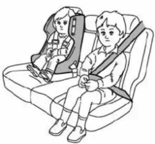
natural_image
Illustration of two children seated in car seat, one wearing a seatbelt (no text or symbols)100350

WARNING
Putchildrenaged12andunderina rearseatproperlyrestrainedatall times.TheSRSairbag deployswith
considerablespeedandforceand caninjureorevenkillchildren, especiallyiftheyare12yearsof ageandunderandarenotrestrainedorimproperlyrestrained. Becausechildrenarelighterand weakerthanadults,theirriskof beinginjuredfromdeploymentis greater.Consequently,westrongly recommendthatALLchildren(includingthoseinchildseatsand thoseethaveoutgrownchildrestraintdevices)sitinaREARseat properly restrainedatalltimesina childrestraintdeviceorinaseatbelt,whicheverisappropriatefor thechild'sage,heightandweight. AlwayssecureALLtypesofchild restraint devices(including forward facingchildseats)inoneoftherear seatingpositionsrecommended in thisOwner'sManual.
NEVERINSTALLAREARWARDFACINGCHILDSEATINTHEFRONT SEAT.DOINGSORISKSSERIOUS INJURYORDEATHTOTHECHILD BYPLACINGTHECHILD'SHEAD TOOCLOSETOTHESRSAIRBAG.
According to accident statistics, children are safer when properly restrained in there are seating positions than in the front seating posi-
tions.Forinstructionsandprecautionsconcerningchildrestraintsystems,referto"Childrestraintsystems"1-31.
Powerseat
▼Forwardandbackwardadjustment
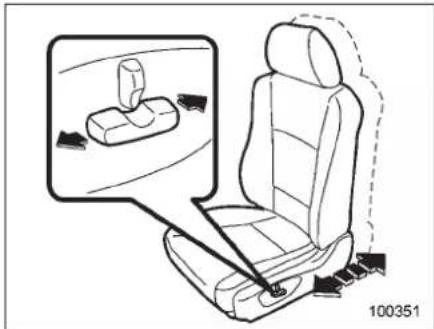
Toadjusttheseatforwardorbackward, movethecontrolswitchforwardorbackward.
NOTE
Duringbackward-forwardadjustment oftheseat,youcannotadjusttheseat cushionangleorseatheight.
▼Recliningtheseatback
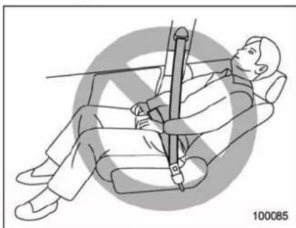
natural_image
Illustration of a person seated in a chair using a vertical bar device, with no visible text or symbols.WARNING
Topreventthepassengerfromslidingundertheseatbeltintheeventofacollision,alwaysputtheseatbackintheuprightpositionwhilethevehicleisinmotion.Also,donotplaceobjectssuchascushionsbetweenthepassengerandtheseatback.Ifyoudoso,theriskofslidingunderthelapbeltandofthelapbeltslidingupovertheabdomenwillincrease,andbothcanresultinseriousinternalinjuryordeath.
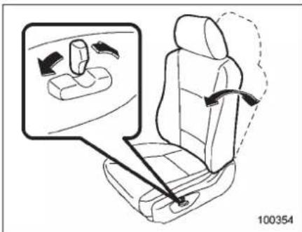
Toadjusttheangleoftheseatback,move thecontrolswitch.
▼Seatcushionangleadjustment (driver'sseat)
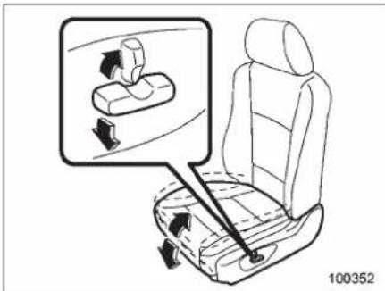
Toadjusttheseatcushionangle, pullup or pushdown the front end of the control
-CONTINUED-
1-4 Seat, seatbelt and SRSairbags
switch.
▼Seatheightadjustment(driver's seat)
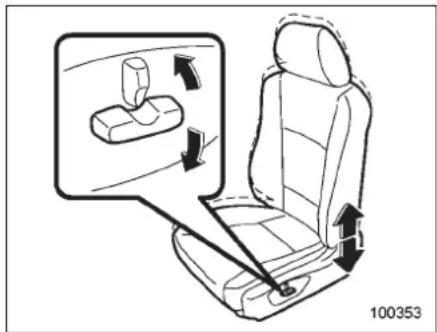
Toadjusttheseatheight, pulluporpush downtherearendofthecontrolswitch.
■ Memoryfunction(driver's seat-ifequipped)
Two of your favorite seat positions can be registered. Register these seat position with button "1" or "2" and retrieve the seat position by pressing either button.
The followingseat positions can be registered.
●Forward/backwardpositionoftheseat
- Angleofseatback
- Angleofseatcushion
●Heightofseat
▼Registrationofseatposition
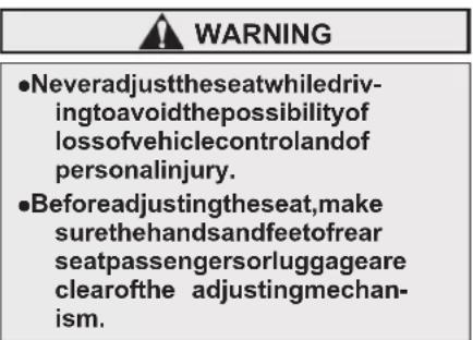
- With these select lever in the "P" position, adjust these at position.
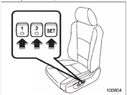
- While pressing the "SET" button, press
the desired button "1" or "2".
- Thechimesoundsonce, and theseat positionisregistered.
▼Retrievalofseatposition
WARNING
- Never retrieve the seat position whiledrivingtoavoidthepossibilityofloss ofvehiclecontrol andofpersonalinjury.
- Performtheseatpositionretrievalbeforedriving.Besureto confirmthattheselectlever positionisinthe“P”position. Donotdriveuntiltheretrievalof theseatpositioniscomplete.
- Besuretopressthecorrect buttonoretrieveyour registered seatposition.Iftheseatposition is not optimum for you, it may adversely affect your driving and may reduce the effectiveness of theseatbelt.That could result in an accident involving serious injury or death.
- When retrieving a registered seat position, make sure the hands, feet and possessions of rear seat passengers are clear of these seat adjusting mechanism.
- Whenanytroubleoramalfunc- tionoccursduringtheretrievalof theseatposition,stoptheretri- valoftheseatpositionusingany ofthecontrolswitchesforman- ualadjustment,seatmemoryset button,seatmemoryregistered button1or2.
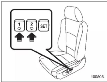
- With these select lever in the "P" position, press the desired button "1" or "2".
- The chimesoundsonce and these at movestotheregistered position.
- Whenteseat movestotheregistered position, the chimesoundstwice.
NOTE
- Ifanewpositionisregisteredforthe
samebutton, thepreviousseatpositionisdeleted.
- Evenifthebatteryisdisconnected, theregisteredseatpositionisnot deleted.
■Headrestraintadjustment
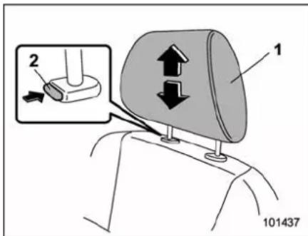
1) Headrestraint 2) Releasebutton
Both the driver's seat and the front passenger's seat are equipped with head restraints.
Theheadrestraintshouldbeadjustedso thatthecenteroftheheadrestraintis closesttothetopoftheoccupant'sears.
Toraise:
Pulltheheadrestraintup.
Tolower:
Pushtheheadrestraintdownwhile pressingthereleasebuttononthetopof theseatback.
Toremove:
Whilepressingthereleasebutton, pullout theheadrestraint.
Toinstall:
Installtheheadrestraintintotheholesthat arelocatedonthetopoftheseatbackuntil theheadrestraintlocks.

WARNING
●Neverdrivethevehiclewiththe headrestraintsremovedbecause theyaredesignedtoreducethe riskofseriousneckinjuryinthe eventthatthevehicleisstruck from the rear. Therefore, when youremovetheheadrestraints, you must reinstall all head restraintstoprotectivevehicleoccupants.
- Alloccupants, including the driver, should not operate a vehicle or sitin a vehicle's seat until the headrestraints are replaced in their proper positions in order to minimize risk of neck injury in the
-CONTINUED-
1-6 Seat, seatbelt and SRSairbags
eventofacrash.
■Activeheadrestraint
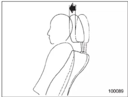
natural_image
Line drawing of human head and neck anatomy with directional arrow indicating movement (no text or symbols)The front seat of your vehicle are equipped with active head restraints. They automatically tilt forwards slightly in the event the vehicle is struck from therear, decreasing the amount of rear forward head movement and thus reducing the risk of whiplash. Form maximum effectiveness the head restraint should be adjusted so that the center of the head restraint is closest to the top of the occupant's ears.
CAUTION
- Eachactiveheadrestraintis effectiveonlywhenitsheightis properlyadjustedandthedriver/passengersitsinthecorrect positionontheseat.
- If your vehicle is involved a rear-end collision, have an authorized SUBARU dealer-in-specttheactiveheadrestraints.
•Theactive headrestraints may not operate in the event the vehicle experiences only as light impact in therear. - The activehead restraintsmaybe damagediftheyarepushedhard frombehindorsubjectedto shock.Asaresult,theymaynot function if the vehicle suffers a rearimpact.
Lumbarsupport
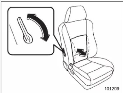
Pulltheleverforwardorbackward. Pullingtheleverforwardwillincrease the amountofsupportforyourlowerback. Pullingtheleverbackwardwilldecrease theamountofsupportforyourlowerback.
Seatheater(ifequipped)
Theseatheaterisequippedinthefront seats.
Theseatheateroperateswhentheignitionswitchisinthe"ON"position.
Theseatheatercanbeadjustedinthree levels.Pressthebuttontoactivatethe seatheater.Eachsubsequentpressofthe buttonwillreducethelevel.Pushingthe buttonfourtimesorkeepingthebutton pressedforapproximately1secondwill turntheheateroff.Whiletheseatheateris operating,itsoperatinglevelisshownby thenumberofilluminatedindicators.To warmtheseatasquicklyaspossible,set theheaterwiththreeindicatorsilluminated.
Whenthevehicle'sinterioriswarmed enoughorbeforeyouleavethevehicle, alwaysturntheswitchoff.

CAUTION
- Thereisapossibilitythatpeople withdelicateskinmaysuffer slightburnsevenatlowtemperaturesiftheyusetheseatheater foralongperiodoftime.When usingtheheater,alwaysbesure towaranthepersonsconcerned.
- Donotputanythingontheseat whichinsulatesagainstheat, suchasablanket,cushion, or similaritems.Thismaycausethe seatheatertooverheat.
NOTE
Useoftheseatheaterforalongperiod oftimewhiletheengineisnotrunning cancausebatterydischarge.
Rearseats(5-seatermodels)/Second-rowseats(7-seater models)
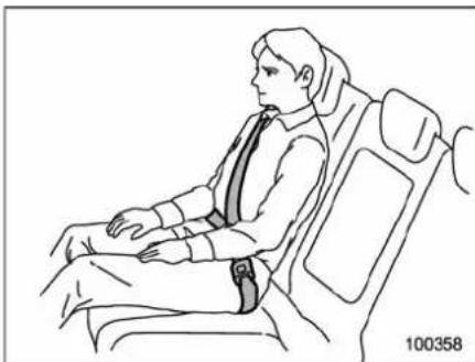
natural_image
Line drawing of a person seated in a car seat, wearing a seatbelt and headband (no text or symbols)
WARNING
- Seatbelts provide maximum restraint when the occupant sits wellbackanduprightintheseat. Donotputcushionsoranyother materialsbetweenoccupants andseatbacksorseatcushions. Ifyoudoso,theriskofsliding underthelapbeltandofthelap beltslidingupovertheabdomen willincrease,andbothcanresult inseriousinternalinjuryor death.
-CONTINUED-
1-8 Seat,seatbeltandSRSairbags
- Beforeadjustingtheseat,make surethehandsandfeetofthe rearseatpassengersareclearof theadjustingmechanism(7-sea- termodelsonly).

CAUTION
Neveradjusttheseatwhiledriving. Doingsoisdangerousastheseat couldmoverapidlyandyoucould beinjured.
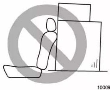
natural_image
Simple line drawing of a person sitting on a bench with a no-smoking symbol in the background (no text or symbols)
WARNING
Neverstackluggageorothercargo higherthanthetopoftheseatback becauseitcouldtumbleforwardand
injurepassengersintheeventofa suddenstoporaccident.
■Forwardandbackwardadjustment
▼5-seatermodels
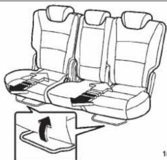
natural_image
Line drawing of a car seat assembly with rear seats and side compartments, showing no text or symbolsPulltheleverupwardandslidetheseatto thedesiredposition. Thenreleasethe leverandmovetheseatbackandfortho makesurethatitissecurelylockedinto place.
▼7-seatermodels
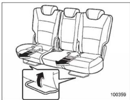
natural_image
Line drawing of a car seat with seat covers and seatbelt, showing no text or symbolsPulltheleverupwardandslidetheseatto thedesiredposition.
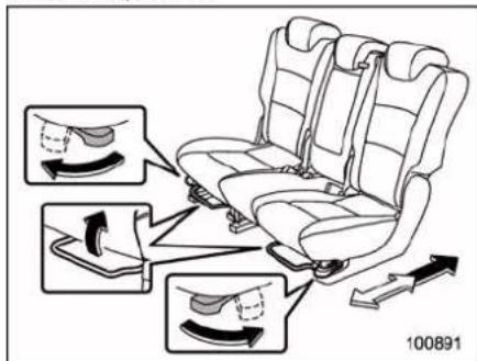
Whentherightseatortheleftseatpairis slidrearward, itstopspartwayatthelock pointsoasnottotrapthelegsof
passengerssittingonthethird-rowseat. Itispossibletoslidetheseatorseatpair furtherrearwardbyreleasingthelockthat stopsit. Todothis, simultaneouslypullthe leverundertheoutboardseatcushionand turntheleveronthesideoftheseat cushionoutwardwhenslidingtheseator seatpair.
Onceyouhavereleasedthelock,youcan slidetheseatorseatpairbackandforth withonlytheleverundertheseatcushion pulled.Ifyouslidetheseatorseatpair forwardofthelockpoint,youwillneedto releasethelockagainbeforeyoucan slideitbehindthepoint.
Thenreleasetheleverandmovetheseat backandforhtomakesurethatitis securelylockedintoplace.

CAUTION
Ifyouslidetheseatorseatpairaft ofthelockpointwhilethethird-row seatisoccupied, be careful not to trap the leg so fthethird-row pas- sengers.
■Recliningtheseatback
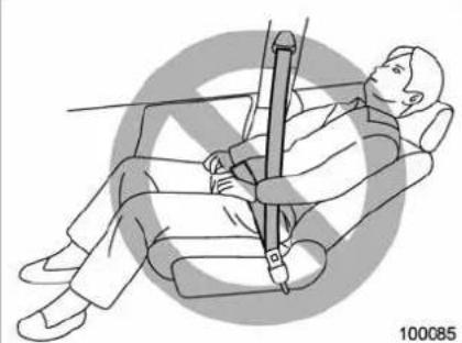
natural_image
Illustration of a person seated in a chair using a seatbelt device, with no visible text or symbols.
WARNING
Topreventthepassengerfromslidingundertheseatbeltintheeventofacollision,alwaysputtheseatbackintheuprightpositionwhilethevehicleisinmotion.Also,donotplaceobjectssuchascushionsbetweenthepassengerandtheseatback.Ifyoudoso,theriskofslidingunderthelapbeltandofthelapbeltslidingupovertheabdomenwillincrease,andbothcanresultinseriousinternalinjuryordeath.

CAUTION
- In7-seatermodels,neverallow thethird-rowseatpassengersto adjusttheseatbackofthesesecondrow.Doingsoisdangerous astheseatbackwilltilrapidly andcouldinjurethepassengers.
- If the cargo area cover is equipped, be careful not top inch your hand between the headrest and the cargo area cover when you're clin there are seat.
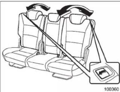
natural_image
Diagram of a car seatbelt with directional arrows indicating rotation, no text or symbols presentPulltheleverupandadjusttheseatback tothedesiredposition.
Thenreleasetheleverandmakesurethe seatbackissecurelylockedintoplace.
-CONTINUED-
1-10 Seat,seatbeltandSRSairbags
■ Foldingdowntheseatback

WARNING
●Afterreturningtheseattoits originalposition,becertainto placealloftheseatbeltsandthe tabattachedtotheseatcushion abovetheseatcushion.And makecertainthattheshoulder beltsarefullyvisible.
●Neverallowpassengerstoride onthefoldedseatbackorinthe cargoarea.Doingsomayresult inseriousinjuryordeath.
- Secureskisandotherlengthy itemsproperlytopreventthem frombeingthrownaroundinside thevehicleandcausingserious injuryduringasuddenstop,a suddensteeringmaneuverora rapidacceleration.
- Ifpassengers are sitting on the third-rowseat, never drivewhile folding these second-rowseat. It can be as serious interference at the time of braking and impact.
- If passengersaresitting on the third-rowseat, never drivewhile the centerseatback of these second-rowseatisfolded. Doing so
may result in serious injury in the eventofahardbrakingoran impact.
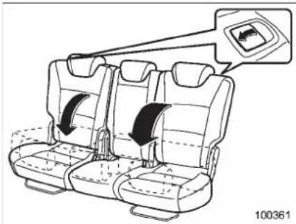
natural_image
Diagram of car seat compartments with directional arrows indicating movement, no text or symbols present1.Slidetheseatorseatpairtoits rearmostposition.
2. Lowertheheadrestrainttoitslowest position. Refer to "Head restraint adjustment" 1-11.
3. Unlocktheseatbackbypullingthe leverandthenfoldtheseatbackdown.
4. To return the seatback to its original position, raisetheseatbackuntillocks into place. Make sure it is securely locked.
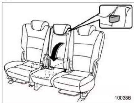
natural_image
Diagram of a car seatbelt assembly with an inset showing the seatbelt being inserted (no text or symbols present)Bypullingthetabonthecenterseat, you canfoldonlytheseatbackofthecenter seat.
Toreturntheseatbacktoitsoriginal position, raisetheseatbackuntil itlocks into place. Make sure it is securely locked.
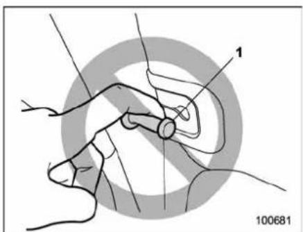
natural_image
Medical illustration showing a hand holding a device with labeled point '1' and reference number 100681 (no text or symbols beyond labels)1) Bar
- Raisetheseatbackofthecenter seatwhiletakingcarenottotrap yourhandsorotherpartsofthe bodybetweenthecenterseat andwindow-sideseat.
NOTE
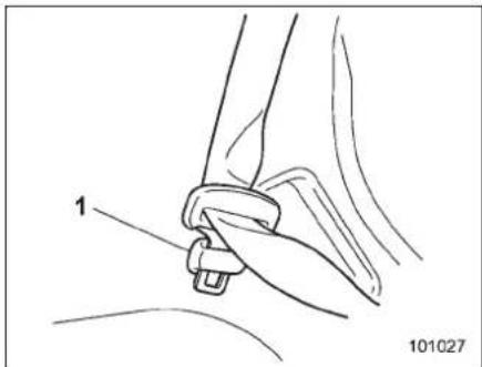
natural_image
Line drawing of a car seatbelt buckle being adjusted for a seatbelt, showing no text or symbols1) Holder
●Foldingtheseatbackofthecenterseatwillexposethebarthat retainsitintheraisedposition. Becarefulnottohurtyourselfon it.Especially,donotrestyour fingeronthebar. Otherwise, whenteseatbackisraised,your fingercouldbepinchedbetween thebarandseatbackandthus injured.
With theseatbackfolded, attach the tongue plate of each rear /second-row seat belt to the corresponding holder. Do the same alsobeforesomeonegets into the third -rowseat.
■Headrestraintadjustment
Boththerearwindowsideseatsandthe rearcenterseatareequippedwithhead restraints.

WARNING
●Neverdrivethevehiclewiththe headrestraintsremovedbecause theyaredesignedtoreducethe riskofseriousneckinjuryinthe eventthatthevehicleisstruck fromtherear.
- Alloccupants, including the driver, should not operate a vehicle or sitin vehicle's seat until the headrestraints are placed in their proper positions in order to minimize risk of neck injury in the event of a crash.

CAUTION
The headrestraint is not intended to be used at the lowest position. Beforesitting on theseat, raise the headrestraint to an appropriate position depending on your sitting height.
-CONTINUED-
1-12 Seat,seatbeltandSRSairbags
▼Windowsideseats
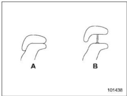
natural_image
Two hand-drawn diagrams labeled A and B, showing abstract curved shapes without any text or symbols.A) Whennotused(retractedposition) B) Whenused(extendedposition)
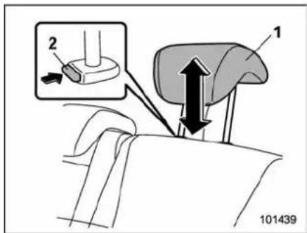
1) Headrestraint 2) Releasebutton
Toraise:
Pulltheheadrestraintup.
Tolower:
Push the head restraint down while pressing there lease button on the top of these at back.
Theheadrestraintshouldbeadjustedso thatthecenteroftheheadrestraintis closesttothetopoftheoccupant'sears. Whentheseatsarenotoccupied,lower theheadrestraintstoimproverearward visibility.
▼Centerseat
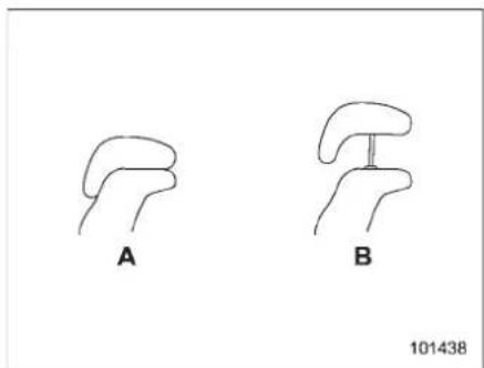
natural_image
Two hand-drawn anatomical diagrams labeled A and B, with no text or symbols on the shapes themselves.A) Whennotused(retractedposition) B) Whenused(extendedposition)
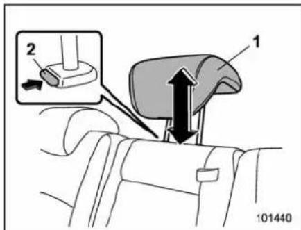
1) Headrestraint 2) Releasebutton
Toraise:
Pulltheheadrestraintup.
Tolower:
Push the head restraint down while pressing there lease button on the top of these at back.
Theheadrestraintshouldbeadjustedso thatthecenteroftheheadrestraintis closesttothetopoftheoccupant'sears. Whenthecenterseatisnotoccupied, lowertheheadrestrainttoimproverearwardvisibility.
Armrest
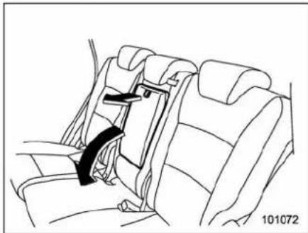
natural_image
Line drawing of a car seatbelt with a belt buckle, no text or symbols presentTolowerthearmrest, pullonthestrapof thearmrest.

WARNING
To avoid the possibility of serious injury, passengers must never be allowed to sit on the center arm rest while the vehicle is in motion.
Third-rowseat(7-seater models)
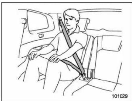
natural_image
Line drawing of a person sitting in a car seatbelt, no text or symbols present
WARNING
Seatbeltsprovide maximum restraintwhentheoccupantsitswell backanduprightintheseat.Donot putcushionsoranyothermaterials betweenoccupantsandseatbacks orseatcushions.Ifyoudoso,the riskofslidingunderthelapbeltand ofthelapbeltslidingupoverthe abdomenwillincrease,andbothcan resultinseriousinternalinjuryor death.
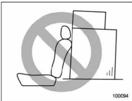
natural_image
Simple line drawing of a person kneeling with a box, no text or symbols present
WARNING
Neverstackluggageorothercargo higherthanthetopoftheseatback becauseitcouldtumbleforwardand injurepassengersintheeventofa suddenstoporaccident.
■Accesstothethird-rowseat
Thereareleversonbothsidesofthe second-rowseat. Eachleverisusedto facilitateaccesstothethird-rowseat.

WARNING
Initsslid-forwardpositionwiththe seatbacktippedforward,thesecond-rowseatisnotlockedandfree
-CONTINUED-
1-14 Seat, seatbelt and SRSairbags
tomove.Donotdrivethevehicle withtheseatinthisstateorallow anyonetositontheseatunlessitis completelylocked.Doingsomay resultinseriousinjuryordeath.

CAUTION
When getting into or out of the third-row seat, makes sure these second-row seatis in the completely slid-forward position and besure to watch your step.
▼Toaccessthethird-rowseat
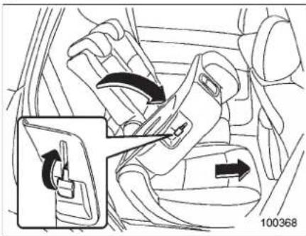
natural_image
Car seatbelt mechanism diagram showing clockwise and clockwise movement (no text or symbols)Raisethelever. Theseatbackofthe second-rowseatwilltipforwardandthe seatwillslideforward.
Beforedrivingthevehicle,adjustthefore/aftpositionofthesecond-rowseat,raise theseatback,andmakesuretheseatback issecurelylockedinposition.
▼Togetoutfromthethird-rowseat
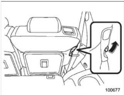
natural_image
Line drawing of a car interior showing seatbelt and door panel, with an inset close-up highlighting the door handle (no text or symbols)Raisetheleverfromthethird-rowseat.
Theseatbackofthesecond-rowseatwill tipforwardandtheseatwillslideforward. Beforedrivingthevehicle,adjustthefore/aftpositionofthesecond-rowseat,raise theseatback,andmakesuretheseatback issecurelylockedinposition.
■ Foldingdowntheseatback

WARNING
- Afterreturningtheseattoits originalposition,becertainto placealloftheseatbeltsandthe tabattachedtotheseatkushion abovtheseatkushion.And makecertainthattheshoulder beltsarefullyvisible.
- Neverallowpassengerstoride onthefoldedseatbackorinthe cargoarea.Doingsomayresult inseriousinjuryordeath.
- Secureskisandotherlengthy itemsproperlytopreventthem frombeingthrownaroundinside thevehicleandcausingserious injuryduringasuddenstop,a suddensteeringmaneuveror a rapidacceleration.
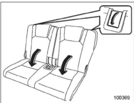
natural_image
Line drawing of a car seatbelt with two side seats and a belt buckle (no text or symbols)Placetheheadrestraintinitslowest position, pullupthelevertoreleasethe seatbacklock, andfolddowntheseat-back. Referto "Headrestraintadjustment" 1-15.
Toreturntheseatbacktoitsoriginal position, raisetheseatbackuntillocks intoplace. Makesureitissecurelylocked.
NOTE
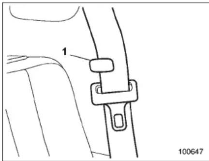
1) Holder
●Beforefoldingorraisingtheseat-backofthethird-rowseat,confirmthat theseatbeltisflatagainstthesidewall atthelowerpointandthewebbingis attachedtotheholder.
- When raising these seat back of the third-row seat, if the seat belt catches on these seat back, hold the belt forward of these seat back while latching the seat back.
■Headrestraintadjustment
Both the third-row seats are equipped with head restraints.

WARNING
●Neverdrivethe vehiclewith the headrestraints removed because theyaredesignedtoreducethe riskofseriousneckinjuryinthe eventthatthe vehicleisstruck fromtherear.
- Alloccupants, including the driver, should not operate a vehicle or sitin a vehicle's seat until the head restraints are placed in their proper positions in order to minimize risk of neck injury in the event of a crash.
1-16 Seat,seatbeltandSRSairbags
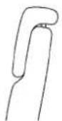
A
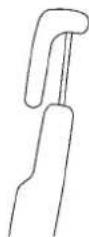
B
101441
A) Whennotused(retractedposition)
B)Whenused(extendedposition)
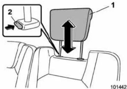
1) Headrestraint
2)Releasebutton
Toraise:
Pulltheheadrestraintup.
Tolower:
Push the head restraint down while pressing there lease button on the top of these at back.
Theheadrestraintshouldbeadjustedso thatthecenteroftheheadrestraintis closesttothetopoftheoccupant'sears. Whentheseatsarenotoccupied,lower theheadrestraintstoimproveearward visibility.

CAUTION
The headrestraintis not intended to be used at the lowest position. Beforesitting on theseat, raise the headrestraint to an appropriate position depending on your sitting height.
Seatbelts
■ Seatbeltsafetytips

WARNING
- Allpersonsinthevehicleshould fasten their seatbelts BEFORE thevehiclestartstomove. Otherwise, the possibility ofserious injurybecomesgreaterinthe eventofasuddenstoporaccident.
- All belts should fit snugly in order to provide full restraint. Loose fittingbeltsarenotaseffectivein preventingorreducinginjury.
- Eachseatbeltis designed to supportonlyoneperson.Never useasinglebeltfortwoormore persons—evenchildren.Otherwise,inanaccident,serious injuryordeathcouldresult.
-Replaceall seatbeltassemblies includingretractorsandattachinghardwarewornbyoccupants ofavehiclethathasbeenina seriousaccident.Theentireassemblyshouldbereplacedeven ifdamageisnotobvious. - Put childrenaged12andunderin
arearseatproperlyrestrainedat alltimes.TheSRSairbagde- ployswithconsiderablespeed andforceandcaninjureoreven killchildren,especiallyiftheyare 12yearsofageandunderand arenotrestrainedorimproperly restrained.Becausechildrenare lighterandweakerthanadults, theirriskofbeinginjuredfrom deploymentisgreater.Consequently,westronglyrecommend thatALL children(including thoseinchildseatsandthose thathaveoutgrownchildre- straintdevices)sitinaREAR seatproperlyrestrainedatall timesinachildrestraintdevice orinaseatbelt,whicheveris appropriateforthechild'sheight andweight.
AlwayssecureALLtypesof child restraintdevices(includingforwardfacingchildseats)inoneof therearseatingpositionsrecommendedinthisOwner'sManual. NEVERINSTALLAREARWARD FACINGCHILDSEATINTHE FRONTSEAT.DOINGSORISKS SERIOUSINJURYORDEATHTO THECHILDBYPLACINGTHE CHILD'SHEADTOOCLOSETO
THESRSAIRBAG.
According to accident statistics, children are safer when properly restrained in therearseating position than the front seating positions. For instructions and precautions concerning the childrestraintsystem, refer to "Childrestraintsystems" 1-31.
Yourvehicleisequippedwithacrash sensinganddiagnosticmodule,whichwill recordtheuseoftheseatbelt(s)bythe driverandfrontpassengerwhenanyof theSRSfrontal,sideandcurtainairbags deploy.
▼Infantsorsmallchildren
Useachildrestraintsystemthatis suitableforyourvehicle.Referto"Child restraintsystems" 1-31.
▼Children
Ifachildistoobigforachildrestraint system, the child should sit in the rear seat andberestrainedusingtheseatbelts. Accordingtoaccidentstatistics,children aresaferwhenproperlyrestrainedinthe rearseatingpositionsthaninthefront seatingpositions.Neverallowachildto standuporkneelontheseat.
If the shoulder portion of the belt crosses
thefaceorneck,adjusttheshoulderbelt anchorheight(window-sideseatingpositionsonly) andthenifnecessaryymovethe childclosertothebeltbuckletohelp provide a good shoulder belt fit. Care must betakentosecurelyplacethelapbeltas lowaspossibleonthehipsandnotonthe child'swaist.lftheshoulderportionofthe beltcannotbeproperlypositioned,achild restraintsystemshouldbeused.Never placetheshoulderbeltunderthechild's armorbehindthechild'sback.
▼Expectantmothers
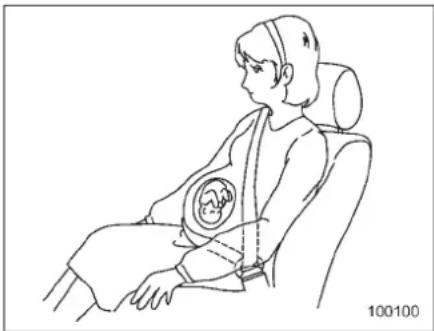
natural_image
Line drawing of a person seated in a car seat with an infant seat, no text or symbols presentExpectantmothersalsoneedtousethe seatbelts. Theyshouldconsult theirdoctor for specific recommendations. The lap belt shouldbewornsecurelyandaslowas possibleoverthehips, notoverthewaist.
-CONTINUED-
1-18 Seat,seatbeltandSRSairbags
EmergencyLockingRetractor(ELR)
Thedriver'sseatbelthasanEmergency LockingRetractor(ELR).
The emergency locking retractor allows normal body movement but theretractor locks automatically during a sudden stop, impactorify up pull the belt very quickly out of theretractor.
■Automatic/EmergencyLockingRetractor(A/ELR)
Eachpassenger'sseatbelthasanAutomatic/EmergencyLockingRetractor(A/ELR).TheAutomatic/EmergencyLockingRetractornormallyfunctionsasanEmergencyLockingRetractor(ELR).TheA/ELRhasanadditionallockingmode "AutomaticLockingRetractor(ALR) mode"intendedtosecureachildrestraint system.Whentheseatbeltisoncedrawn outcompletelyandisthenretractedeven slightly,theretractorlocktheseatbeltin thatpositionandtheseatbeltcannotbe extended.Asthebeltisrewinding,clicks willbeheardwhichindicatetheretractor functionsasALR.Whentheseatbeltis retractedfully,ALRmodeisreleased.
Whensecuringachildrestraintsystemon thepassengers'seats,theseatbeltmust bechangedovertotheAutomaticLocking
Retractor(ALR)mode.
When the childrestraint system is removed, makesurethattheretractoris restored to the EmergencyLockingRetractor (ELR) function by allowing the seatbeltoretractfully.
Forinstructionsonhowtoconvertthe retractortotheALRmodeandrestoreitto theELRmode,referto"Installingchild restraint systems with A/ELR seatbelt" 1-34.
■ Seatbeltwarninglight andchime
Yourvehicleisequippedwithaseatbelt warningdeviceatthedriver'sandfront passenger'sseat.
Withtheignitionswitchturnedtothe"ON" position,thisdeviceremindsthedriver andfrontpassengertofastentheirseatbeltsbyilluminatingthewarninglights in the locations indicated in the following illustrationsandsoundingachime.

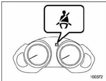
Driver's warninglight
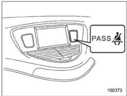
Frontpassenger'swarninglight
▼ Operation
Ifthedriverand/orfrontpassengerhave/hasnotyetfastenedtheseatbelt(s)when
theignitionswitchisturnedtothe"ON" position, theseatbeltwarninglight(s)will flashfor6seconds,towarnthatthe seatbelt(s)is/areunfastened.Ifthedriver'sseatbeltisnotfastened,achimewill alsosoundsimultaneously.
NOTE
- Ifthedriver'sand/orfrontpassenger'sseatbelt(s)is/arestillnotfastened 6secondslater,theseatbeltwarning deviceoperatesasfollowsaccording tothevehiclespeed.
- Atspeedslowerthanapproximately9mph(15km/h)
The warninglight(s) for unfastened seatbelt(s) will alternate between steady illumination and flashing at 15-second intervals. The chimewill not sound. - Atspeedshigherthanapproximately9mph(15km/h) Thewarninglight(s)forunfastened seatbelt(s)willalternatebetween flashingandsteadyilluminationat 15-secondintervalsandthechime willsoundwhilethewarninglight(s) is/areflashing.
- Itispossibletocancelthewarning operationthatfollowsthe6-second warningafterturningONtheignition switch.Whentheignitionswitchis
turnedONnexttime,however,the completesequenceofthewarning operationresumes.Forfurtherdetails aboutcancelingthewarningoperation, pleasecontactyourSUBARUdealer.
Ifthereisnopassengeronthefront passenger'sseat,theseatbeltwarning device for the front passenger's seat will bedeactivated.Thefrontpassenger's occupantdetectionsystem monitors whetherornotthereisapassengeron thefrontpassenger'sseat.
Observethefollowingprecautions.Failure todosomaypreventthedevicefrom functioningcorrectlyorcausethedevicetofail.
- Donotinstallanyaccessorysuchasa tableorTVontotheseatback.
- Donotstoreaheavyloadinthe seatbackpocket.
- Donotallowtherearseat/second-row seatoccupanttoplacehis/herhandsor legsonthefrontpassenger'sseatback, or allowhim/hertopulltheseatback.
If theseatbeltwarningdeviceforthefront passenger'sseatdoesnotfunctioncor- rectly (e.g., it is activated even when the frontpassenger'sseatisemptyoritis deactivated even when thefrontpassen- ger has not fastenedhis/herseatbelt), takethefollowingactions.
- Ensure that no article is placed on the seat other than a child restraint system and the child occupant.
- Ensure that there is no article left in the seatback pocket.
If these seat belt warning device for front passenger's seat still does not function correctly after taking relevant corrective actions described above, immediately contact your SUBARU dealer for an inspection.
■Fasteningthe seatbelt

WARNING
- Neveruseabeltthatistwistedor reversed.Inanaccident,thiscan increasetheriskorseverity of injury.
- Keepthelapbeltaslowas possibleonyour hips. In a collision, this spread the force of the lap belt over stronger hip bones instead of acrossthe weaker abdomen.
- Seatbeltsprovidemaximumre- straintwhen theoccupant sits wellbackanduprightintheseat. Toreducetheriskofsliding under the seatbelt in a collision,
-CONTINUED-
1-20 Seat,seatbeltandSRSairbags
thefrontseatbacksshouldbe alwaysusedintheuprightpositionwhilethevehicleisrunning. Ifthefrontseatbacksarenot usedintheuprightpositionina collision,theriskofslidingunder thelapbeltandofthelapbelt slidingupovertheabdomenwill increase,andbothcanresult in seriousinternalinjuryordeath. -Donotputcushionsoranyother materialsbetweenoccupants andseatbacksorseatcushions. Ifyoudoso,theriskofsliding underthelapbeltandofthelap beltslidingupovertheabdomen willincrease,andbothcanresult inseriousinternalinjuryor death.
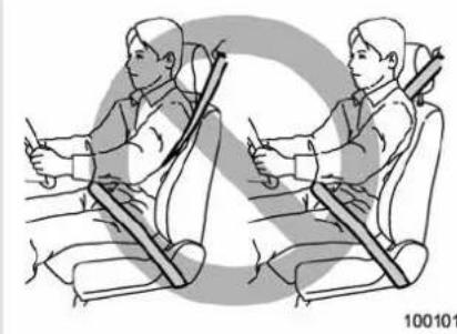
natural_image
Illustration of a person seated in a car seat using a seatbelt, showing two different positions (no text or symbols present)
WARNING
Neverplacetheshoulderbeltunder thearmorbehindtheback. Ifan accidentoccurs, this can increase theriskorseverity of injury.

CAUTION
Metallicpartsoftheseatbeltcan becomeveryhotinavehiclethat hasbeenclosedupinsunnyweather;theycouldburnanoccupant.Do nottouchsuchhotpartsuntilthey cool.
▼Frontseatbelts
- Adjusttheseatpositionaccordingto thefollowingprocedure.
Driver'sseat: Adjusttheseatbacktothe uprightposition.Movetheseatbackasfar fromthesteeringwheelaspracticalwhile stillmaintainingfullvehiclecontrol.
Frontpassenger'sseat: Adjusttheseat-backtotheuprightposition.Movetheseat asfarbackaspossible. - Sitwellbackintheseat.
- Pickupthetongueplateandpullthe beltoutslowly.Donotletitgettwisted.If thebeltstopsbeforereachingthebuckle, returnthebeltslightlyandpullitoutmore slowly.Ifthebeltstillcannotbeunlocked, letthebeltretractslightlyaftergivingita strongpull,thenpullitoutslowlyagain.
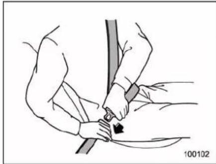
natural_image
Illustration of a person using a cable to lift a seatbelt, showing the angle of movement (no text or symbols present)- Insertthetongueplate into the buckle until you hear a click.
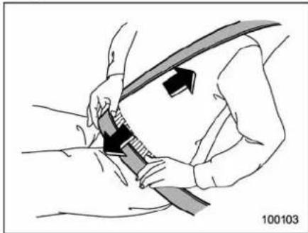
natural_image
Illustration of a person adjusting a car seatbelt with a belt, showing mechanical components (no text or symbols)5.Tomakethelapparttight,pullupon theshoulderbelt. 6.Placethelapbeltaslowaspossible onyourhips,notonyourwaist.
Adjustingthefrontseatshoulder beltanchorheight
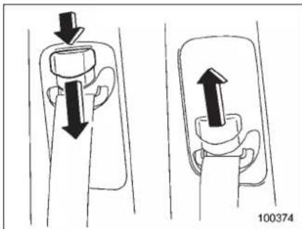
natural_image
Diagram showing two mechanical components with directional arrows indicating movement, no text or symbols presentTheshoulderbeltanchorheightshouldbe adjustedtothepositionbestsuitedforthe driver/frontpassenger.Alwaysadjustthe anchorheightsothattheshoulderbelt passesoverthemiddleoftheshoulder withouttouchingtheneck.
Toraise:
Slidetheanchorup.
Tolower:
Pushthereleasebuttonandslidethe anchordown.
Pulldownontheanchortomakesurethat itislockedinplace.

WARNING
Whenwearingtheseatbelts,make suretheshoulderportionofthe webbingdoesnotpassoveryour neck.Ifitdoes,adjusttheseatbelt anchortoalowerposition.Placing theshoulderbeltovertheneckmay resultinneckinjuryduringsudden brakingorinacollision.
∇Unfasteningtheseatbelt
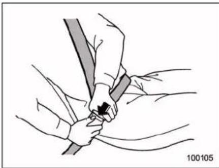
natural_image
Illustration of hands holding a cable with a small arrow indicating force or movement (no text or symbols)Pushthebuttononthebuckle.
Beforeclosingthedoor, makesurethat thebeltsareretractedproperlytoavoid catchingthebeltwebbinginthedoor.
-CONTINUED-
1-22 Seat,seatbeltandSRSairbags
▼Rearseatbelts(5-seatermodels)/Second-rowseatbelts(7-seater models)—excludingcenterseatbelt
- Sitwellbackintheseat.
- Pickup the tongue plate and pull the belt out slowly. Donot let it get twisted. If the belt stops before reaching the buckle, return the belts slightly and pull it out more slowly. If the belt still cannot be unlocked, let the belt retracts slightly after giving a strong pull on it, then pull it out slowly again.
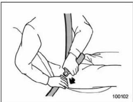
natural_image
Illustration of a person adjusting a seatbelt with a belt, showing hands and a curved arrow (no text or symbols)- Insertthetongueplateintothebuckle untilyouhearaclick.
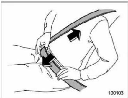
natural_image
Illustration of a person adjusting a seatbelt with an arrow indicating force (no text or symbols)- Tomakethelapparttight, pullupon theshoulderbelt.
- Placethelapbeltaslowaspossible onyourhips, notonyourwaist.
Adjusting the shoulder belt anchor height (rearseatsof5-seater models/second-rowseatsof7-seater models)
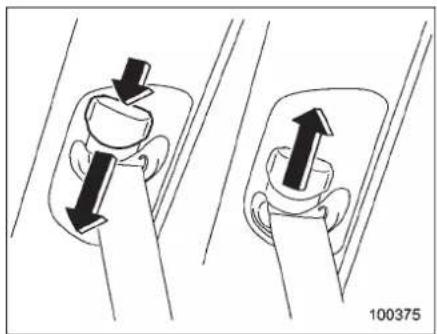
natural_image
Diagram showing two mechanical components with directional arrows indicating movement, no text or symbols presentTheshoulderbeltanchorheightshouldbe adjustedtothepositionbestsuitedforthe passenger.Alwaysadjusttheanchor heightsothattheshoulderbeltpasses overthemiddleoftheshoulderwithout touchingtheneck.
Toraise:
Slidetheanchorup.
Tolower:
Pushthereleasebuttonandslidethe anchordown.
Pulldownontheanchortomakesurethat itislockedinplace.

WARNING
Whenwearingtheseatbelts,make suretheshoulderportionofthe webbingdoesnotpassoveryour neck.Ifitdoes,adjusttheseatbelt anchortoalowerposition.Placing theshoulderbeltovertheneckmay resultinneckinjuryduringsudden brakingorinacollision.
∇Unfasteningtheseatbelt
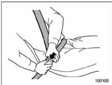
natural_image
Illustration of a person adjusting a seatbelt, no text or symbols presentPushthebuttononthebuckle.
Beforeclosingthedoor, makesurethat thebeltsareretractedproperlytoavoid catchingthebeltwebbinginthedoor.
NOTE
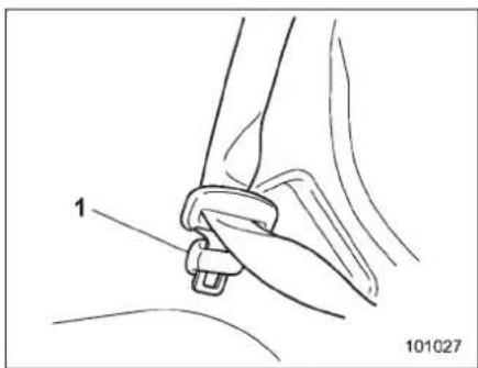
1) Holder
With theseatbackfolded, attach the tongue plate of each rear /second-row seat belt to the corresponding holder. Do the same alsobeforesomeonegets into the third -rowseat.
▼Rearcenterseatbelt(5-seatermodels)/second-rowcenterseatbelt(7-seatermodels)
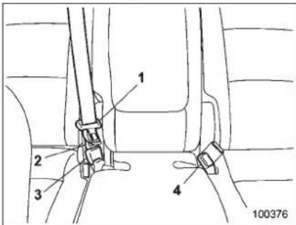
1) Centerseatbelttongueplate
2) Connector(tongue)
3) Connector(buckle)
4) Centerseatbeltbuckle
1-24 Seat, seatbelt and SRSairbags
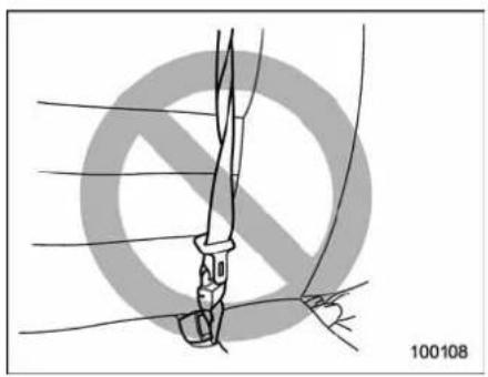
natural_image
Diagram of a hand holding a tool with a circular background and diagonal lines, no text or symbols present.
WARNING
Fasteningtheseatbeltwiththewebbingtwistedcanincreasetheriskor severityofinjuryinanaccident. Whenfasteningthebeltafteritis pulledoutfromtheretractor,especiallywheninsertingtheconnector'stongueplateintothemating buckle(onright-handside),always checkthatthewebbingis not twisted.
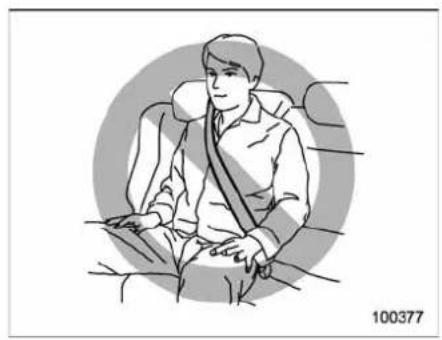
natural_image
Illustration of a person seated in a car seat with a belt, no text or symbols present
WARNING
Besuretofastenbothtongueplates totherespectivebuckles. If the seatbeltisusedonlyasashoulder belt (withtheconnector'stongue platenotfastenedtotheconnector'sbuckleontheright-handside), it cannot properly restrainthewear-inpositioninanaccident, possibly resulting inseriousinjuryor death.
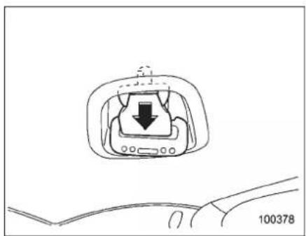
natural_image
Diagram of a car interior showing a directional arrow and labeled component (no text or symbols beyond basic labels)Centerseatbeltisstowedintherecessof theceiling.
- Removetheconnector(tongue)plate from the slot located at the front of the recessbypullingtheconnector(tongue) platerearward.
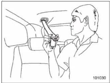
natural_image
Line drawing of a person using a tool on a vehicle (no text or symbols)- Pullout these seat belts slowly from the overhead retractor.
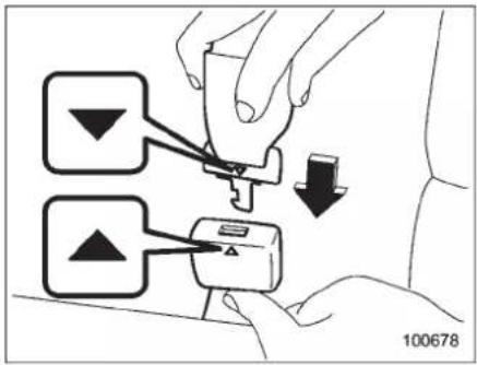
- After confirming that the webbing is not twisted, insert the connector (tongue) attached at the webbing end into the buckle on the right-hand side until a click is heard. Makes sure that the "mark on the connector (tongue) and the " mark on the buckle are aligned. If the belt stops before reaching the buckle, return the belts slightly and pull it out more slowly. If the belt still cannot be unlocked, let the belt retract slightly after giving a strong pull, then pull it out slowly again.
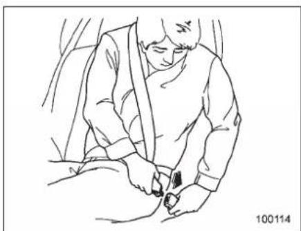
natural_image
Line drawing of a person wearing a seatbelt, seated with hands near the seat (no text or symbols)- Insert the center seat belt tongue plate in the center seat belt buckle marked "CENTER" on the left-hand side until it clicks.
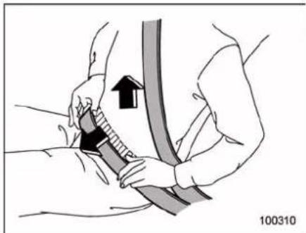
natural_image
Illustration of a person adjusting a seatbelt with an arrow indicating upward motion (no text or symbols)- Tomakethelapparttight, pullupon theshoulderbelt. And placethelapbeltas
lowaspossibleonyourhips,notonyour waist.
∇Unfasteningtheseatbelt
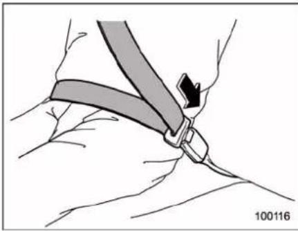
natural_image
Illustration of a hand holding a belt buckle, showing a knot and angle (no text or symbols)Pushthereleasebuttonofthecenter seatbeltbuckle(ontheleft-handside)to unfastentheseatbelt.
1-26 Seat,seatbeltandSRSairbags
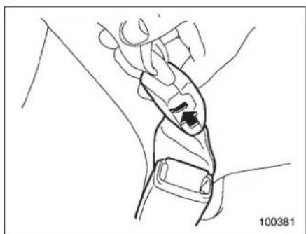
natural_image
Line drawing of a hand holding a wrist with a black object inserted, no text or symbols present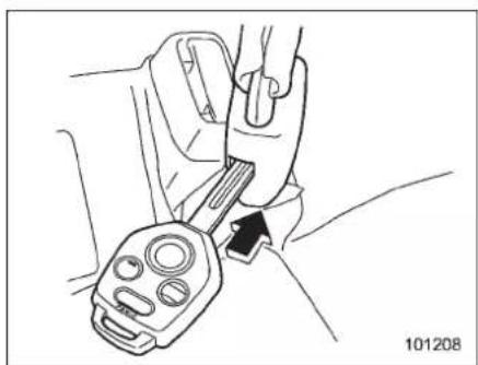
natural_image
Line drawing of a hand using a belt switch to adjust a car seat (no text or symbols)- Insertakeyorotherhardpointed objectintotheslotintheconnector (buckle)ontheright-handsideandpush itin,andtheconnector(tongue)platewill disconnectfromthebuckle.
natural_image
Pure mechanical component diagram without any text, numbers, or symbols- With the beltheld by hand, allow the retractortorollup the belts slowly. You should hold the webbing and guide it back into other retractor while it is rolling up. Neatly store the tongue plate in therecess on the ceiling and then insert the connector (tongue) plate into the slot located at the front of therecess.
natural_image
Diagram of a car seatbelt buckle assembly (no text or symbols)CAUTION
- Donotallowtheretractoroll up the seatbelt too quickly. Otherwise, themetal tongue plates may hit again sthetrim, resulting in damaged trim.
•Havetheseatbeltfullyrolledup sothatthetongueplatesare neatlystored.Ahangingtongue platecanswingandhitagainst thetrimduringdriving,causing damagetothetrim.
▼Third-rowseatbelt(7-seatermodels)
- Sitwellbackintheseat.
- Pickupthetongueplateandpullthe beltoutslowly.Donotletitgettwisted.If thebeltstopsbeforereachingthebuckle, returnthebeltslightlyandpullitoutmore slowly.Ifthebeltstillcannotbeunlocked, letthebeltretractslightlyaftergivinga strongpullonit,thenpullitoutslowly again.
natural_image
Illustration of a person adjusting a seatbelt with a belt, showing mechanical assembly (no text or symbols)- Insertthetongueplate into the buckle until you hear a click.
natural_image
Illustration of a person adjusting a seatbelt with an arrow indicating force (no text or symbols present)- Tomakethelapparttight, pullupon theshoulderbelt.
- Placethelapbeltaslowaspossible onyourhips, notonyourwaist.
∇Unfasteningtheseatbelt
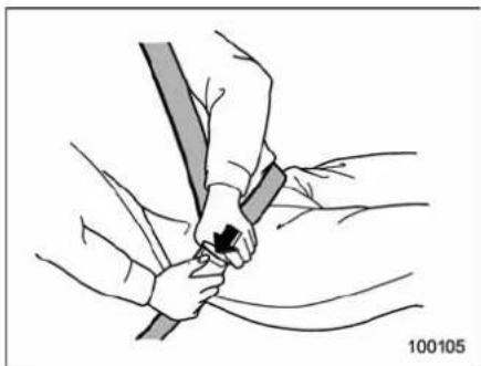
natural_image
Illustration of a person's shoulder and arm fastening a cable (no text or symbols)Pushthebuttononthebuckle.
NOTE
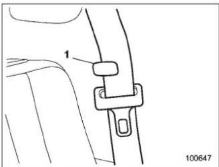
natural_image
Technical line drawing of a car seatbelt buckle assembly (no text or symbols)1) Holder
●Beforefoldingorraisingtheseat-backofthethird-rowseat,confirmthat theseatbeltisflatagainstthesidewall atthelowerpointandthewebbingis attachedtotheholder.
- When raising these seat back of the third-rowseat, if these seat belt catches on these seat back, hold the belt forward of the seat back while latching the seat back.
-CONTINUED-
Seatbeltmaintenance
Tocleantheseatbelts, useamildsoap and lukewarmwater. Neverbleachordye thebelts because this could seriously affect their strength.
Inspecttheseatbeltsandattachments includingthewebbingandallhardware periodicallyforcracks,cuts,gashes, tears,damage,looseboltsorwornareas. Replacetheseatbeltsevenifonlyminor damageisfound.

CAUTION
- Keepthebeltsfreeofpolishes, oils,chemicalsandparticularly batteryacid.
●Neverattempttomakemodificationsor changesthat willprevent theseatbeltfromoperatingproperly.
Frontseatbelt pretensioners
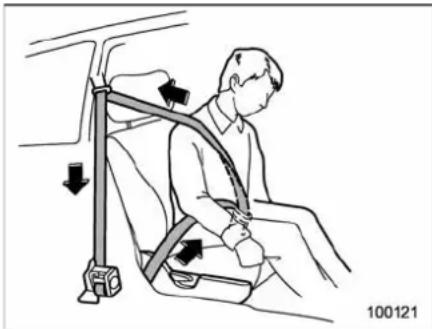
natural_image
Illustration of a person seated in a car seatbelt with arrows indicating force or pressure points (no text or symbols)Thedriver's andfrontpassenger'sseat-beltshaveaseatbeltpretensioner. The seatbelt pretensioners for the driver's seat andfrontpassenger'sseatoperateatthe same timeasthe frontal, andsideSRS airbags. If the vehiclerollsover, they operatesimultaneouslywiththecurtain airbag.
Thefrontand sideairbagsensorsandthe rolloversensorareusedasthepretensionersensors.Ifasensordetectsa certainpredeterminedamountofforce duringafrontalcollision,asideimpact collisionorarollovercollisionofthe vehicle,thefrontseatbeltisquicklydrawn backinbytheretractortotakeupthe slack so that the belt more effectively
restrainsthefrontseatoccupant.
When a seatbelt pretensioner is activated, anoperatingnoisewillbeheardanda small amount of smoke will be released. Theseoccurrencesarenormalandnot harmful. This smoke does not indicate a fireinthevehicle.
Oncetheseatbeltpretensionerhasbeen activated, theseatbeltretractorremains locked. Consequently, the seatbelt can not bepulledoutandretractedandtherefore mustbereplaced.
NOTE
- Seatbeltpretensionersarenotdesigned toactivate inminorfrontal impacts, inminorside impacts or rear impacts.
- Theseatbeltpretensionersforthe driver's seat and front passenger's seatoperateatthesametimeasthe frontal,andsideSRSairbags.Ifthe vehicle rolls over, they operate simultaneouslywiththecurtainairbag.
- Pretensionersaredesignedtofunctiononaone-time-onlybasis.Inthe event that a pretensioner is activated, boththedriver's andfrontpassenger's seatbelt retractorassemblies must be replaced and only by an authorized SUBARUdealer.When replacingseat-
beltretractorassemblies, use only genuine SUBARUparts.
•lfeitherfrontseatbeltdoesnot retractorcannotbepulledoutdueto amalfunctionoractivationofthe pretensioner,contactyourSUBARU dealerassoonaspossible.
- If the front seat belt retractor assembly or surrounding area has been damaged, contact your SUBARU dealer as soon as possible.
- Whenyouselyourvehicle,weurge youtoexplaintothebuyerthatithas seatbeltpretensionersbyalertinghim tothecontentsofthissection.

WARNING
- Toobtainmaximumprotection, occupantsshouldsitinanup-rightpositionwiththeirseatbelts properlyfastened.Referto"Seatbelts" 1-16.
- Donotmodify, removeorstrike thefrontseatbeltretractorassembliesorsurroundingarea. This could result in accidental activation of these seatbelt pretensioners or could make the system in operative, possibly resulting in serious injury. Seatbelt pretensioners havenouser-ser
viceableparts.Forrequiredservicingoffrontseatbeltretractors equippedwithseatbeltpretensioners, see your nearest SUBARUdealer.
- Whendiscardingfrontseatbelt retractorassembliesorscrappingtheentirevehicledueto collisiondamageorforother reasons,consultyourSUBARU dealer.
Systemmonitors
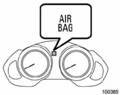
SRSairbagsystemwarninglight
Adiagnosticsystemcontinuallymonitors thereadinessoftheseatbeltpretensioner whilethevehicleisbeingdriven.The seatbeltpretensionerssharethecontrol
modulewiththeairbagsystem.Therefore, ifanymalfunctionoccursinaseatbelt pretensioner,theSRSairbagsystem warninglightwillilluminate.TheSRS airbagsystemwarninglightwillshow normalsystemoperationbylightingfor approximately6secondswhentheignitionswitchisturnedtothe"ON"position.
The following components are monitored by the indicator.
●Frontsubsensor(right-handside)
●Frontsubsensor(left-handside)
●Airbagcontrolmodule(includingimpactandrolloversensors)
- Frontalairbagmodule(driver'sside)
- Frontalairbagmodule(frontpassenger'sside)
- Sideairbagsensor(centerpillarright-handside)
- Sideairbagsensor(centerpillarleft-handside)
- Sideairbagmodule(driver'sside)
- Sideairbagmodule(frontpassenger's side)
- Curtainairbagsensor(rearwheel houseright-handside)
- Curtainairbagsensor(rearwheel houseleft-handside)
●Curtainairbagmodule(right-handside)
- Curtainairbagmodule(left-handside)
-CONTINUED-
1-30 Seat, seatbelt and SRSairbags
- Satellitesafingsensor(undertherear centerseat[5-seatermodels]/underthe second-rowcenterseat[7-seatermodels])
- Seatbeltpretensioner(driver'sside)
- Seatbeltpretensioner(frontpassenger'sside)
- Seatbeltbuckleswitch(driver'sside)
- Seatbeltbuckleswitch(frontpassenger'sside)
- Driver'sseatpositionsensor
- Frontpassenger'sseatbelttension sensor
- Frontpassenger'soccupantdetection systemweightsensor
- Frontpassenger'soccupantdetection controlmodule
- Frontpassenger'sfrontalairbagON andOFFindicator
- Allrelatedwiring
WARNING
Ifthewarninglightexhibitsanyof thefollowingconditions,theremay beamalfunctionintheseatbelt pretensionersand/orSRSairbag system.ImmediatelytakeyourvehicletoyournearestSUBARUdealer tohavethesystemchecked.Unless checkedandproperlyrepaired,the seatbeltpretensionersand/orSRS
airbagswilloperateimproperly(e.g. SRSairbags mayinflate ina very minorcollisionornotinflate ina severecollision),whichmayincreasetheriskofinjury.
- Flashingorflickeringofthewarninglight
- Noilluminationofthewarning lightwhentheignitionswitchis firstturnedtothe"ON"position
•Continuousilluminationofthe warninglight - Illuminationofthewarninglight whiledriving
■ Systemservicing
WARNING
- Whendiscardingaseatbeltretractorassemblyorscrapping theentirevehicledamagedbya collision,consultyourSUBARU dealer.
- Tamperingwithordisconnecting thesystem'swiringcouldresult inaccidentalactivationofthe seatbeltpretensionerand/orairbag orcouldmake thesystem inoperative,whichmayresultin
seriousinjury.Donotuseelectricaltestequipmentonany circuitrelatedtotheseatbelt pretensionerandairbagsystems. Forrequired servicingof theseatbeltpretensioner,see yournearestSUBARUdealer.
CAUTION
Thefrontsubsensors are located on both sides of the radiator panel, and the airbag control module including the impacts sensors is located under the center console. If you need service or repair in those areas near the front seat belt retractors, were recommended that you have an authorized SUBARU dealer perform the work.
NOTE
If the front part of the vehicle is damaged in an accident to the extent that these seat belt pretensioner does not operate, contact your SUBARU dealer as soon as possible.
■Precautionsagainstvehicle modification
AlwaysconsultyourSUBARUdealerif youwanttoinstallanyaccessorypartsto yourvehicle.

CAUTION
Donotperformanyofthefollowing modifications.Suchmodifications caninterferewithproperoperation oftheseatbeltpretensioners.
- Attachmentofanyequipment (bushbar,winches,snowplow, skidplate,etc.)otherthangenuineSUBARUaccessorypartsto thefrontend.
-Modificationofthesuspension systemorfrontendstructure. - Installationofatireofdifferent sizeandconstructionfromthe tiressspecifiedonthevehicle placardattachedtothedoor pillarorspecifiedforindividual vehiclemodelsinthisOwner's Manual.
Childrestraintsystems
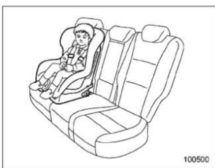
natural_image
Line drawing of a car seat with a person seated in the seat, no text or symbols presentWhileridinginthevehicle,infantsand smallchildrenshouldalwaysbeplacedin aninfantorchidrestraintsysteminoneof therearseatingpositionsrecommended inthisOwner'sManual.
Youshoulduseaninfantorchildrestraint systemthatmeetsFederalMotorVehicle SafetyStandardsorCanadaMotorVehicleSafetyStandards,iscompatiblewith yourvehicleandisappropriateforthe child'sageandsize.
Allchildrestraintsystemsaredesignedto besecuredinvehicleseatsbylapbeltsor thelapbeltportionofalap/shoulderbelt (exceptthosedescribedin"Installationof child restraint systems by use of lower and
tetheranchorages(LATCH)"\~1-38).
Childrencouldbeendangeredan accidentiftheirchildrestraintsarenot properlysecuredinthevehicle.When installingthechildrestraintsystem,carefully follow the manufacturer's instructions.
According to accident statistics, children are safer when properly restrained in the rearseating position than in the front seating positions.
AllU.S.statesandCanadianprovinces requirethatinfantsandsmallchildrenbe restrainedinanapprovedchildrestraint systematalltimeswhilethevehicleis moving.
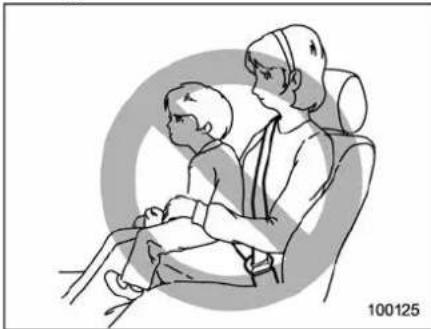
natural_image
Illustration of two children seated in a car seat, viewed from the side (no text or symbols)1-32 Seat,seatbeltandSRSairbags

WARNING
Neverletapassengerholdachild onhisorherlapwhilethevehicleis moving. Thepassengercannotprotectthechildfrominjuryinacollision, because the child will be caught between the passenger and objects inside the vehicle. Additionally, holding a child in your lapar arms in the front seat expose that child to another serious danger. Sincethe SRSairbag deploys with considerable speed and force, the child could be injured even killed.
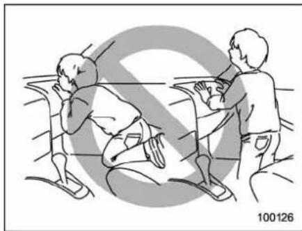
natural_image
Illustration of two people interacting near a table with a diagonal line, no text or symbols present
WARNING
Childrenshouldbeproperlyre- strainedatalltimes.Neverallowa childtostandup,ortokneelonany seat.Unrestrainedchildrenwillbe thrownforwardduringsuddenstop orinanaccidentandcanbeinjured seriously.
Additionally, childrenstandingupor kneelingonorinfrontofthefront seatareexposedanotherserious danger.SincetheSRSairbagde- ployswithconsiderablespeedand force,thechildcouldbeinjuredor evenkilled.
■Wheretoplaceachildre- straintsystem
The following are SUBARU's recommendations on where to place each child restraint system in your vehicle.
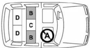
100501
A:Frontpassenger'sseat
Youshouldnotinstallachildrestraint system(includingaboosterseat)dueto thehazardtochildrenposedbythe passenger'sairbag.
B: Rearoutboardseats(5-seatermodels)/second-rowoutboardseats(7-seatermodels)
Recommended positions for all types of childrestraintsystems.
In these positions, Automatic/Emergency Locking Retractor (A/ELR) seat belts and lower anchorages (bars) are provided for installing a childrestraintsystem.
Some types of child restraints might not be able to be secured firmly duetoprojection of these at cushion.
Inthisseatingposition,youshoulduse
onlyachildrestraintsystemthathasa bottombasethatfitssnuglyagainstthe contoursoftheseatcushionandcanbe securelyretainedusingtheseatbelt.
C: Rearcenterseat(5-seatermodels)/second-rowcenterseat(7-seatermodels)
Installingachildrestraintsystemisnot recommended,althoughtheA/ELRseat-beltandanupperanchorage(tether anchorage)areprovidedinthisposition. Sometypesofchildrestraintsmightnotbe abletobesecuredfirmlyduetoprojection oftheseatcushion.
Inthisseatingposition,youshoulduse onlyachildrestraintsystemthathasa bottombasethatfitssnuglyagainstthe contoursoftheseatcushionandcanbe securelyretainedusingtheseatbelt.
D: Third-rowseat(7-seatermodels)
Installingachildrestraintsystemisnot recommended,althoughtheA/ELRseat-beltandtwoupperanchorages(tether anchorages)areprovidedinthesepositions.
Theseseatingpositionsarenotequipped withloweranchorages(bars)forinstalling LATCHsystem-typechildrestraints.However,childrestraintdevicescanbeusedin thesepositionusingtheA/ELRseatbelts and upper anchorages (tetheran-
chorages)provided.
Sometypesofchildrestraintsmightnotbe abletobesecuredfirmlyduetoprojection oftheseatcushion.
Inthisseatingposition,youshoulduse onlyachildrestraintsystemthathasa bottombasethatfitssnuglyagainstthe contoursoftheseatcushionandcanbe securelyretainedusingtheseatbelt.

WARNING
Putchildrenaged12andunderin therearseatproperlyrestrainedat alltimes.TheSRSairbagdeploys withconsiderablespeedandforce andcaninjureorevenkillchildren, especiallyiftheyare12yearsofage andunderandarenotrestrainedor improperlyrestrained.Becausechildrenarelighterandweakerthan adults,theirriskofbeing injured fromdeploymentisgreater.
Consequently, besure tosecure ALLtypesofchildrestraintdevices (includingforwardfacing child seats)intheREARseatsatalltimes. Youshouldchoosearestraintdevice which is appropriate for the child'sage,heightandweight.Accordingtoaccidentstatistics,children are safer when properly re-
strained therear seatingpositionsthaninthefrontseatingpositions.
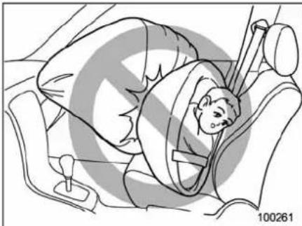
natural_image
Illustration of a person in a car seatbelt, no text or symbols present
WARNING
SINCE YOUR VEHICLE IS EQUIPPEDWITHAPASSENGER'S SRSAIRBAG,DONOTINSTALLA REARWARD FACING CHILD SAFETYSEATINTHEFRONTPASSENGER'SSEAT.DOINGSORISKS SERIOUSINJURYORDEATHTO THECHILDBYPLACINGTHE CHILD'S HEAD TOO CLOSE TO THESRSAIRBAG.
■ Choosingachildrestraint system
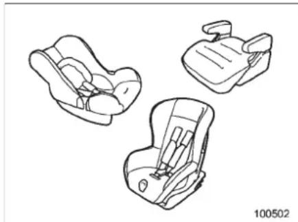
natural_image
Line drawings of three different car seats (no text or symbols)Chooseachildrestraintsystemthatis appropriateforthechild'sageandsize (weightandheight)inordertoprovidethe childwithproperprotection.Thechild restraintsystemshouldmeetallapplic- ablerequirementsofFederalMotorVehicleSafetyStandardsforUnitedStatesor CanadaMotorVehicleSafetyStandards forCanada.Itcanbeidentifiedbylooking forthelabelonthechildrestraintsystem orthemanufacturer'sstatementofcomplianceinthedocumentattachedtothe system.Alsoitisimportantforyouto makesurethatthechildrestraintsystem iscompatiblewiththevehicleinwhichit willbeused.
■InstallingchildrestraintsystemswithA/ELRseatbelt

WARNING
- Childrestraintsystemsandseat-beltscanbecomehotinvehicle thathasbeenclosedupinsunny weather;theycouldburnasmall child.Checkthechildrestraint systembeforeyouplaceachild init.
- Donotleaveanunsecuredchild restraintsysteminyourvehicle. Unsecuredchildrestraintsystemscanbethrownaroundinsideofthevehicleinasudden stop,turnoraccident;theycan strikeandinjurevehicleoccupantsaswellasresultinserious injuriesordeathtothechild.

CAUTION
When you install a child restraint system, follow the manufacturer's instruction supplied with it. After installing the child restraint system, check to ensure that it is held securely in position. If it is no held tight and secure, the danger of your
childsufferingpersonalinjuryinthe eventofanaccidentmaybeincreased.
▼Installingarearwardfacingchild restraint
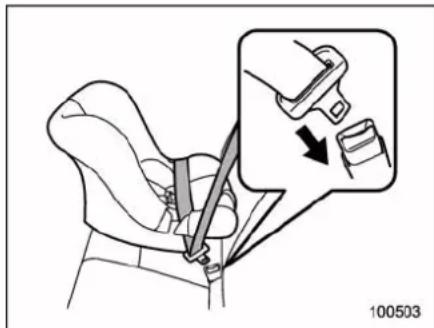
- Slide the seat or seat pair to its rearmostposition.
- Adjusttheseatbacktotheupright position.
- Placethechildrestraintsysteminthe rearseatingposition.
- Runthelapandshoulderbeltthrough oraroundthe childrestraintsystem followingtheinstructionsprovidedbyits manufacturer.
- Insertthetongueplateintothebuckle untilyouhearaclick.
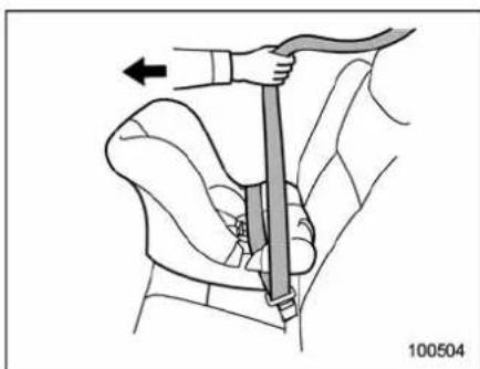
natural_image
Diagram of a car seatbelt buckle being lifted, showing hand placement and motion arrow (no text or symbols)6.Takeuptheslackinthelapbelt.
- Pullout these at belt fully from the retractortochangetheretractor over from the Emergency Locking Retractor (ELR) to the Automatic Locking Retractor (ALR) function. Then, allow the beltorewind into theretractor. Asthe belt is rewinding, clickswill be heard which indicate the retractor functions as ALR.
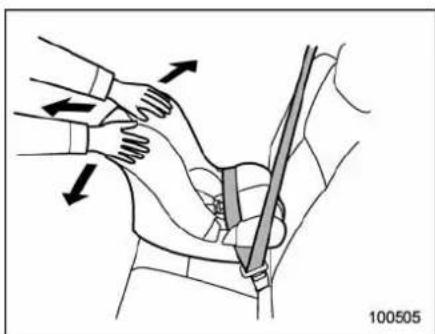
natural_image
Illustration of a person using a belt drive a seatbelt, showing hand placement and motion arrows (no text or symbols)- Pushand pull the child restraint system forward and from sidetosideto check ifitis firmly secured.
Sometimesachildrestraintcanbemore firmlysecuredbypushingitdownintothe seatcushionandthentighteningthe seatbelt.
- Pullattheshoulderportionofthebelt to confirm that it cannot be pulled out (ALR properly functioning).
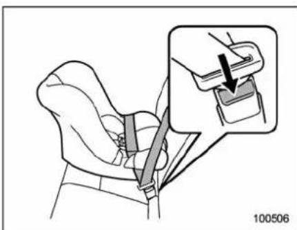
natural_image
Line drawing of a car seatbelt with an inset showing a hand holding a seatbelt (no text or symbols present)- Toremovethechildrestraintsystem, pressthereleasebuttonontheseatbelt buckleandallowthebelttoretract completely. Thebeltwillreturntothe ELRmode.

WARNING
NEVERINSTALLAREARWARDFACINGCHILDSEATINTHEFRONT PASSENGER'S SEAT. DOING SO RISKSSERIOUSINJURY OR DEATH TOTHECHILDBYPLACINGTHE CHILD'S HEAD TOO CLOSE TO THE SRSAIRBAG.
-CONTINUED -
NOTE
Whenthechildrestraintsystemisno longerinuse,removeitandrestorethe ELRfunctionoftheretractor.That functionisrestoredbyretractingthe seatbeltfully.
▼Installingforwardfacingchildre- straint
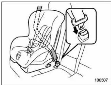
- Slidetheseatorseatpairtoits rearmostposition.
- Adjusttheseatbacktotheupright position.
- Placethechildrestraintsysteminthe seatingposition.
-
Runthelapandshoulderbeltthrough oraroundthechildrestraintsystem followingtheinstructionsprovidedbyits manufacturer.
-
Insertthetongueplateintothebuckle untilyouhearaclick.
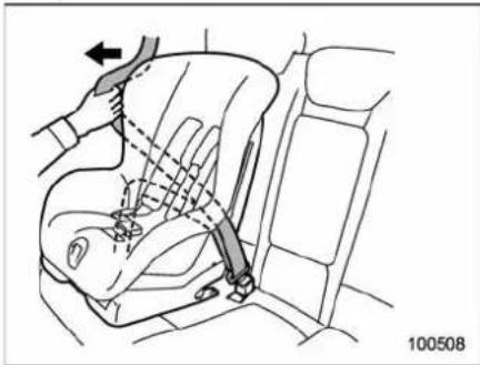
natural_image
Diagram of a car seatbelt mechanism showing hand placement and angle adjustment (no text or symbols)6.Takeuptheslackinthelapbelt.
- Pull out the seatbelt fully from the retractortochangetheretractoroverfrom theEmergencyLockingRetractor(ELR) totheAutomaticLockingRetractor(ALR) function.Then,allowthebelttorewind intotheretractor.Asthebeltisrewinding, clicks will be heard which indicate the retractorfunctionsasALR.
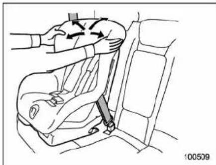
natural_image
Diagram of a car seatbelt with a hand adjusting the seatbelt, showing motion arrows (no text or symbols)- Before having achildsitinthechild restraintsystem, moveitbackandforth and rightandlefttocheckifitisfirmly secured. Sometimesachildrestraint can bemorefirmlysecuredbypushingitdown intothe seatcushion andthentightening theseatbelt.
- Pullattheshoulderportionofthebelt to confirm that it cannot be pulled out (ALR properly functioning).
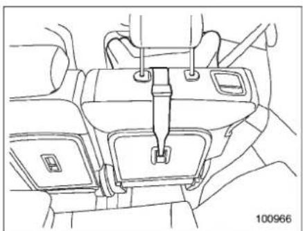
natural_image
Line drawing of a car interior showing seatbelt and dashboard (no text or symbols)Rearseat(5-seatermodels)/Second-row seat(7-seatermodels)
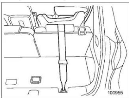
natural_image
Line drawing of a car interior showing a seatbelt and dashboard (no text or symbols)Third-rowseat(7-seatermodels)
10. If the child restraints system requires a toptether, latch the hook onto the top tether anchor and tightent the toptether.
Foradditionalinstructions,referto"Top tetheranchorages" 1-41.
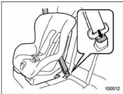
natural_image
Line drawing of a car seatbelt with a magnified inset showing the hook mechanism (no text or symbols)- Toremovethechildrestraintsystem, pressthereleasebuttonontheseatbelt buckleandallowthebelttoretract completely. Thebeltwillreturntothe ELRmode.
NOTE
Whenthechildrestraintsystemisno longerinuse,removeitandrestorethe ELRfunctionoftheretractor.That functionisrestoredbyallowingthe seatbelttoretractfully.
■Installingaboosterseat

WARNING
- Childrestraintsystemsandseat-beltscanbecomehotinavehicle thathasbeenclosedupinsunny weather;theycouldburnasmall child.Checkthechildrestraint systembeforeyouplaceachild init.
- Donotleaveanunsecuredchild restraintsysteminyourvehicle. Unsecuredchildrestraintsystemscanbethrown around inside of the vehicle in a sudden stop,turnoraccident;theycan strikeandinjurevehicleoccupantsaswellasresultinserious injuriesordeathtothecchild.

CAUTION
When you install a child restraint system, follow the manufacturer's instruction supplied with it. After installing the child restraint system, check to ensure that it is held securely in position. If it is no held tight and secure, the danger of your child suffering personal injury in the event of an accident maybe in
-CONTINUED-
creased.
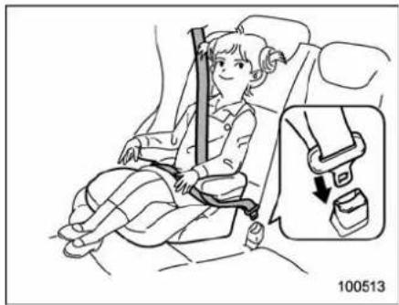
natural_image
Illustration of a child seated in a car seat with a highlighted seatbelt device (no text or symbols)- Slidetheseatorseatpairtoits rearmostposition.
- Placetheboosterseatintherear seatingpositionandsitthechildonit. The childshouldsitwellbackonthebooster seat.
- Runthelapandshoulderbeltthrough oraroundtheboosterseatandthechild followingtheinstructionsprovidedbyits manufacturer.
- Insertthetongueplateintothebuckle untilyouhearaclick.Takecarenotto twisttheseatbelt.
Makesuretheshoulderbeltispositioned acrossthecenterofchild'sshoulderand thatthelapbeltispositionedaslowas possibleonthechild'ships.
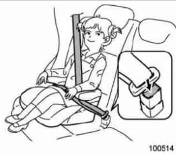
natural_image
Illustration of a child sitting in a car seatbelt, with an inset showing the same seatbelt (no text or symbols present)- Toremovetheboosterseat, pressthe releasebuttonontheseatbeltbuckleand allowthebelttoretract.

WARNING
- Neveruseabeltthatistwistedor reversed.Inanaccident,thiscan increase the risk or severity of injurytothechild.
- Never place the shoulder belt underthechild'sarmorbehind the child'sback.If anaccident occurs,thiscanincreasetherisk orseverityofinjurytothechild.
- Theseatbeltshouldfitsnuglyin ordertoprovidefullrestraint. Loose fitting belts are not as
effective in preventing or reducing injury.
- Placethelapbeltaslowas possibleon thechild's hips. A high-positioned lapbeltwillin- creasetheriskofslidingunder thelapbelt andofthe lapbelt slidingupover the abdomen, and bothcanresultinseriousinternalinjuryordeath.
- Make sure the shoulder belt is positionedacrossthecenter of child'sshoulder.Placingthe shoulderbeltovertheneckmay resultinneckinjuryduringsuddenbrakingorinacollision.
■ Installationofchildrestraint systemsbyuseoflowerand tetheranchorages(LATCH)

WARNING
- Childrestraintsystemsandseat-beltscanbecomehotinavehicle thathasbeenclosedupinsunny weather;theycouldburnasmall child.Check the childrestraint systembeforeyouplaceachild init.
• Donotleaveanunsecuredchild
restraintsysteminyourvehicle. Unsecuredchildrestraintsystemscanbethrownaroundinsideofthevehicleinasudden stop,turnoraccident;theycan strikeandinjurevehicleoccupantsaswellasresultinserious injuriesordeathtothechild.

CAUTION
Whenyouinstallachildrestraint system, followthemanufacturer's instructionssuppliedwithit. After installingthechildrestraintsystem, checktoensurethatitisheld securelyinposition.Ifitisnotheld tightandsecure,thedangerofyour childsfufferingpersonalinjuryinthe eventofanaccidentmaybeincreased.
Sometypesofchildrestraintsystemscan beinstalledinarearseatingpositionof yourvehiclewithoutuseoftheseatbelts. Suchchildrestraintsystemsaresecured tothededicatedanchoragesprovidedon thevehiclebody. Thelowerandtetheranchoragesare sometimesreferredtoastheLATCH system (Lower Anchors and Tethers for CHildren).
101210
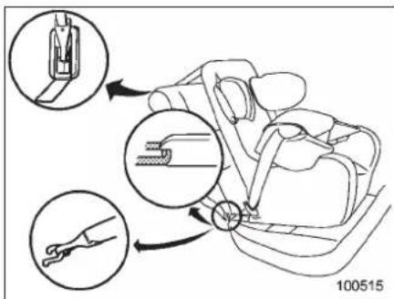
Your vehicle is provided with child restraint systemanchorsasfollows.
- Fourloweranchorages(bars)and threeupperanchorages(tetheranchorages)ontherearseat(5-seater model)/second-rowseat(7-seatermodel)
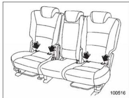
natural_image
Line drawing of three identical car seats with seat covers and accessories, no text or symbols presentLoweranchoragesforchildrestraintsare providedinthefollowinglocations.
- 5-seatermodels:ontherearseats
- 7-seatermodels:onthesecond-row seats
Foreachwindow-sideseatingposition, twoloweranchoragesareprovided. Eachloweranchorageislocatedwhere theseatcushionmeetstheseatback.
1-40 Seat,seatbeltandSRSairbags
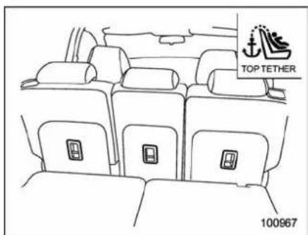
The tether anchorages (upper anchorages) are provided for all these seating positions of therearse at (5-seatermodels)/second-rowseat (7-seatermodels).
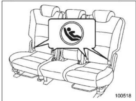
natural_image
Line drawing of a car seat with a circular sign indicating a person inside, no text or symbols presentOneachoutboardrear/second-rowseat, youwillfindmarks" "atthebottomofthe
seatback.
Eachloweranchorageislocatedwhere theseatcushionmeetstheseatback.

CAUTION
When you install a child restraint system, follow the manufacturer's instruction supplied with it. After installing the child restraint system, check to ensure that it is held securely in position. If it is no held tight and secure, the danger of your child suffering personal injury in the event of an accident maybe increased.
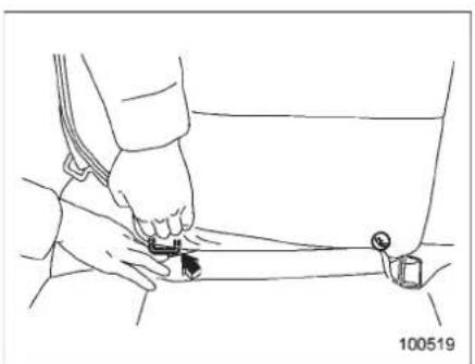
natural_image
Line drawing of a person adjusting a seatbelt with a belt buckle (no text or symbols)-
Slidetheseatorseatpairtoits rearmostposition.
-
Makethe clearance between these seat cushion and seat backalittlewiderto locatethetwoanchorages (bars) for the position where you want to install the child restraintsystem.
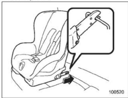
natural_image
Line drawing of a car seatbelt with a magnified inset showing the handle (no text or symbols)- While following the instruction supplied by the childrestraintsystemmanufacturer, connect the lower hooks onto the lower anchorages located at "markson the bottom of theseatback. When the hooks are connected, makes sure the adjacent seat belts are not caught.
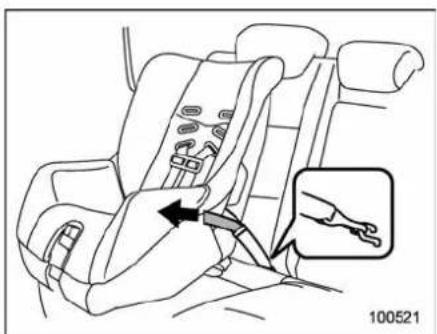
natural_image
Line drawing of a car seatbelt with a hand inserting a cable to the seat, showing no text or symbols.-
If your child restraints system is a flexible attachment type (which uses tether belt to connect the child restraint system properly to the lower anchorages), while pushing the child restraint into the seat cushion, pull both left and right lower tether belts to secure the child restraint system firmly by taking up the slack in the belt.
-
Connectthetoptetherhooktothe tetheranchorageandfirmlytightenthe tether.Forinformationonhowtosethte toptether,referto"Toptetheranchorages" 1-41.
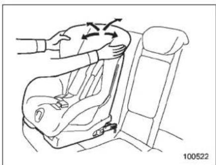
natural_image
Line drawing of a car seat assembly with arrows indicating motion direction (no text or symbols)-
Beforeseatingachildinthechild restraintsystem, trytomoveseatback andforthandleftandrighttoverifythatit isheldsecurelyinposition.
-
Toremovethechildrestraintsystem, followthereverseproceduresofinstallation.
If you have any question concerning this typeof childrestraintsystem, ask your SUBARUdealer.
■ Toptetheranchorages
Yourvehicleisequippedwiththreetop tetheranchorages(fivein the7-seater models)sothatachildrestraint system havingatoptethercanbeinstalledina rearseatingposition.Wheninstallinga childrestraintsystemusing top tether, proceed asfollows,while observingthe
instructionsbythechildrestraintsystem manufacturer.
Sinceatoptethercanprovideadditional stability byoffering anotherconnection betweenachildrestraintsystemandthe vehicle, werecommendthatyouuseatop tetherwheneveroneisrequiredoravailable.
▼ Tetheranchoragelocation
Rearseat(5-seatermodels)/Second-rowseat(7-seatermodels)
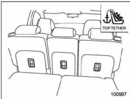
Threetetheranchorages, i.e., onesforthe right, centerandleftseats, arealready installed on the back of each seatback. Openthecoverflaptouseeachanchorage.
-CONTINUED-
1-42 Seat,seatbeltandSRSairbags
Third-rowseat(7-seatermodels)
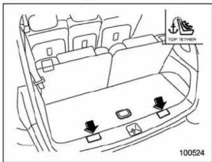
Twotetheranchoragesareattachedtothe rearedgeofthecargoarea.
Openthecoverflaptouseeachanchorage.
▼Tohookthetoptether
▽Rearseat(5-seatermodels)/Second-rowseat(7-seatermodels)
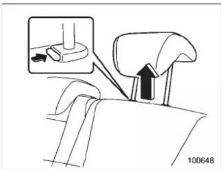
- Raisetheheadrestrainttothehighest positionattheseatingpositionwherethe childseathasbeeninstalledusingthe seatbeltorloweranchorages;liftupthe headrestraintwhilepressingtherelease button.
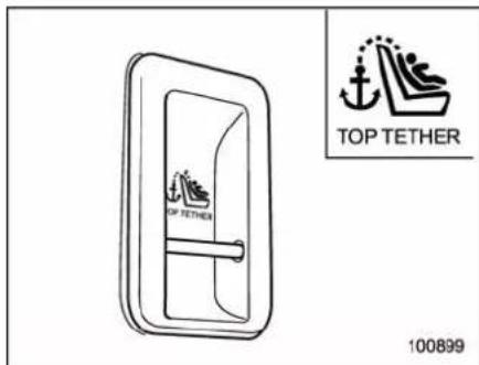
- Confirm that there are no obstacles around the anchorages.
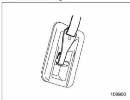
natural_image
Technical line drawing of a mechanical component with a handle and internal structure (no text or symbols)3.Fastenthetoptetherhookofthechild restraintsystemtotheappropriateupper anchorage.
4. Tightenthetoptethersecurely.

CAUTION
Whenthechildrestraintsystemisto besecuredusingthetoptether, passthetoptetherunderthehead restraintbetweentheheadrestraint stayposts.
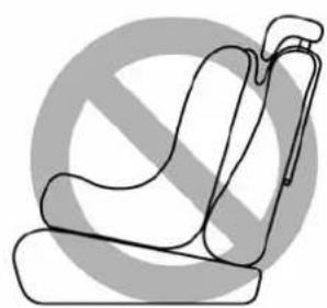
natural_image
Line drawing of a seatbelt device with no text or symbols100671

CAUTION
Besuretoinstallthetoptetherwith theheadrestrainraisedtothe highestposition.Iftheheadrestraintisinanyofthelowerpositions,thetoptetherwilltouchthe headrestraintandtheresulting slackwillpreventitssecureinstallation.
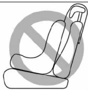
natural_image
Line drawing of a car seat with no text or symbols100672

CAUTION
Donotroutethetoptetheroverthe headrestraint.Itmayhappenthat thetoptethercannotbefastened tightly.
Third-rowseat(7-seatermodels)
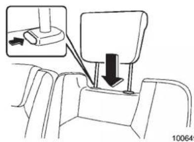
natural_image
Diagram of a vehicle gear shift lever system with an inset showing the wheel and gear (no text or labels)100649
- Lowertheheadrestrainttoitslowest position.
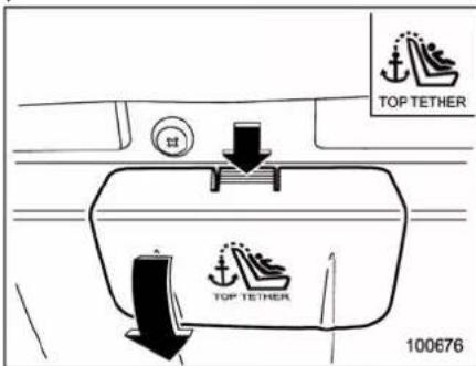
- Opentheliidofthecargoarea, then removethecoversfortheanchorages.
-CONTINUED-
1-44 Seat, seatbelt and SRSairbags
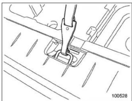
natural_image
Technical line drawing of a mechanical assembly with no visible text or symbols- Fastenthetoptetherhookofthechild restraintsystemtotheappropriateupper anchorage.
- Tightenthetoptethersecurely.
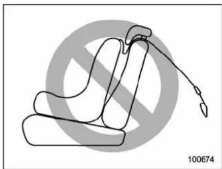
natural_image
Line drawing of a seated object with a curved handle and a pointed tip, set against a circular background with diagonal lines (no text or symbols)CAUTION
Donotpassthetoptetherunderthe headrestraint. Thetoptetherwill touchtheheadrestraintandthe resultingslackwillpreventitssecureinstallation.
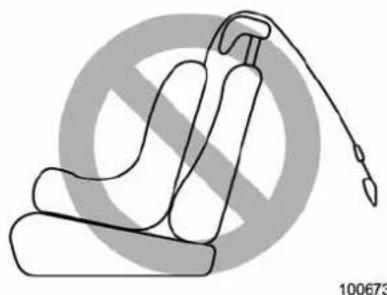
natural_image
Line drawing of a seatbelt device with a diagonal crossed-out symbol in the background (no text or labels)CAUTION
Donotusethetoptetherwiththe headrestraintinaraisedposition, otherwisethetoptethercannotbe fastenedtightly.
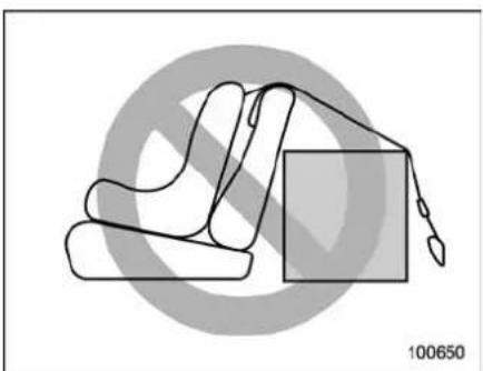
natural_image
Illustration of a hand holding a box with a diagonal line, enclosed in a circular frame (no text or symbols)CAUTION
Preventthetoptetherfromtouching cargointhecargoarea.Thetop tethermaybecomeslackifthe cargochangesshapeormoves.
\*SRSairbag(Supplemental RestraintSystemairbag)
*SRS: Thisstandsforsupplementalrestraintsystem. Thisnameisusedbecausetheairbagsystemsupplementsthe vehicle'sseatbelts.
Yourvehicleisequippedwithacrash sensinganddiagnosticmodule,whichwill recordtheuseoftheseatbelt(s)bythe driverandfrontpassengerwhenanyof theSRSfrontal,sideandcurtainairbags deploy.Therecordedinformationcannot betransmittedtoanycentralcommunica- tionssystemorotherexternaldevice.
■Yourvehicle'sSRSconfiguration
Thedriver'sseat, thefrontpassenger's seat, and theoutboardseat softherear/secondseatingrowofyourvehicleare eachprovidedwith, inadditiontoalap/shoulderbelt, oneormoreairbagsas follows.
- Frontalairbag(oneeachfordriver's seatandfrontpassenger'sseat)
- Sideairbag(oneeachfordriver'sseat andfrontpassenger'sseat)
- Curtainairbag(oneeachfortheoutboardsidesofcabin,extendingfrom driver'sandfrontpassenger'sseatsto
rear/secondseatingrow)
TheseSRSairbagsaredesignedonly asasupplementtotheprimaryprotec-tionprovidedbytheseatbelt.
Thesystemalsocontrolsfrontseatbelt pretensioners. Foroperationinstructions and precautions concerning theseatbelt pretensioner, refer to "Frontseatbeltpretensioners" 1-28.

WARNING
- To obtain maximum protection in the event of an accident, the driver and all passengers in the vehicles should always wear seat belts when the vehicle is moving. The SRS air bag is designed only as a supplement to the primary protection provided by these seat belt. It does not do away with the need to fast seat belts. In combination with these seat belts, it offers the best combined protection in case of a serious accident.
Notwearingaseatbeltincreases thechanceofsevereinjuryor deathinacrashevenwhenthe vehiclehastheSRSairbag.
Forinstructionsandprecautions concerningtheseatbeltsystem,
referto"Seatbelts" 1-16.
- Donotsitorleanunnecessarily close tothe SRSairbag. Because the SRSairbagdeployswith considerablespeed–fasterthan theblinkofaneye–andforceto protectinhighspeedcollisions, theforceofanairbagcaninjure anoccupantwhosebodyistoo closetoSRSairbag.
Itisalsoimportanttowearyour seatbelttohelpavoidinjuries thatcanresultwhentheSRS airbagcontactsanoccupantnot improperpositionsuchasone thrownforwardduringpre-accidentbraking.
Evenwhenproperlypositioned, thereremainsapossibilitythat anoccupantmaysufferminor injurysuchasabrasionsand bruisestotheface orarms becauseoftheSRSairbagdeploymentforce.
●TheSRSairbagsdeploywith considerablespeedandforce. Occupantswhoareoutofproper positionwhentheSRSairbag deploys could suffer very serious injuries.Because the SRSairbag needsenoughspacefordeploy-
ment, the drivers should always sit upright and well back in the seat as far from the steering wheel as practical while still maintaining full vehicle control and the front passengers should mov these seat as far back as possible and sit upright and well back in these seat.
- Donotplaceanyobjectsoveror neartheSRSairbagcoveror betweenyouandtheSRSairbag. IftheSRSairbagdeploys,those objectscouldinterferewithits properoperationandcouldbe propelledinsidethevehicleand causeinjury.
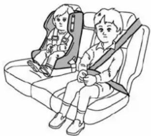
natural_image
Illustration of two children seated in car seats, one wearing a seatbelt (no text or symbols)100350

WARNING
- Put children aged 12 and under in arearseatproperlyrestrainedat alltimes.TheSRSairbagde-ployswithconsiderablespeed andforceandcaninjureoreven killchildren,especiallyiftheyare 12years ofageandunderand arenotrestrainedorimproperly restrained.Becausechildrenare lighter andweakerthanadults, their risk of being injured from deploymentisgreater.
Consequently, westrongly recommend that ALL children (including those in child seats and those that have out grown child restraint devices) sitina REAR seat properly restrained at all times in child restraint device orinaseatbelt, whichever is appropriate for the child's sage, height and weight.
Always secureALLtypesofchild restraintdevices(includingforwardfacingchildseats)inoneof therearseatingpositionsrecommendedinthisOwner'sManual.
According to accident statistics, childrenaresaferwhenproperly
restrainedintherearseating positionsthaninthefrontseat-ingpositions.
Forinstructionsandprecautions concerningthechildrestraint system,referto"Childrestraint systems" 1-31.
- NEVER INSTALL A REARWARD FACINGCHILDSEATINTHE FRONTSEAT.DOINGSORISKS SERIOUSINJURYORDEATHTO THECHILDBYPLACINGTHE CHILD'SHEADTOOCLOSETO THESRSAIRBAG.
●Neverallowachildtostandup, ortokneelonthefrontpassenger'sseat,orneverholdachild onyourlaporinyourarms.The SRSairbagdeployswithconsiderableforceandcaninjureorevenkillthechild.

CAUTION
- When the SRSairbag deploys, somesmokewillbereleased. This smokecould cause breathing problems for people with a history of asthma or other breathing trouble. If you or your passengers have breathing pro-
blemsafterSRSairbagdeploys, getfreshairpromptly.
- AdeployingSRSairbagreleases hotgas. Occupantscouldget burnediftheycomeintodirect contactwiththehotgas.
NOTE
Whenyousellyourvehicle,weurge youtoexplaintothebuyerthatitis equippedwithSRSairbagsbyalerting himorhertotheapplicablesectionin thisOwner'sManual.
-CONTINUED-
1-48 Seat,seatbeltandSRSairbags
▼Components
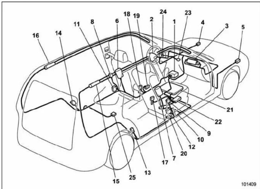
1) Airbagcontrolmodule(including impact and rolloversensors)
2)Frontalairbagmodule(driver'sside)
3) Frontalairbagmodule(frontpassenger's side)
4) Frontsubsensor(left-handside)
5) Frontsubsensor(right-handside)
6)Sideairbagmodule(driver'sside)
7) Sideairbagmodule(frontpassenger's side)
8) Sideairbagsensor(centerpillarleft-hand side)
9) Sideairbagsensor(centerpillarright-handside)
10)Airbagwiring
11)Seatbeltpretensioner(driver'sside)
12) Seatbeltpretensioner(frontpassenger's side)
13) Curtainairbagsensor(rearwheelhouse right-handside)
14) Curtainairbagsensor(rearwheelhouse left-handside)
15)Curtainairbagmodule(right-handside)
16) Curtainairbagmodule(left-handside)
17) Seatbeltbuckleswitch(frontpassenger's side)
18)Seatbeltbuckleswitch(driver'sside)
19)Driver'sseatpositionsensor
20)Frontpassenger'sseatbelttensionsensor
21) Frontpassenger'soccupantdetection systemweightsensor
22) Frontpassenger'soccupantdetection controlmodule
23)Frontpassenger'sfrontalairbagONand OFFindicator
24)SRSairbagsystemwarninglight
25) Satellitesafingsensor(undertherear centerseat[5-seatermodels]/underthe second-rowcenterseat[7-seatermodels])
■ SUBARUadvancedfrontal airbagsystem
YourvehicleisequippedwithaSUBARU advancedfrontalairbagsystemthatcomplieswiththenewadvancedfrontalairbag requirementsintheamendedFederal MotorVehicleSafetyStandard(FMVSS) No.208.
The SUBARUadvancedfrontalairbag systemautomaticallydeterminesthedeploymentforceofthedriver'sSRSfrontal airbagatthetimeofdeploymentaswellas whetherornottoactivatethefront passenger'sSRSfrontalairbagand,if activated,thedeploymentforceofthe SRSfrontalairbagatthetimeofdeployment.
Yourvehiclehaswarninglabelsonthe driver'sandfrontpassenger'ssunvisors beginningwiththephrase "EVEN WITH ADVANCEDAIRBAGS" and atag attachedtotheglovebox lidbeginning withthephrase"EvenwithAdvancedAir Bags".Makesurethatyoucarefullyread theinstructionsonthewarninglabelsand tag.
Alwayswearyourseatbelt. The SUBARU advancedfrontalairbagsystemisa supplementalrestraint systemand must beusedincombinationwithaseatbelt. All occupants should wear a seatbelt or be seatedinanappropriatechildrestraint
system.
Thedriver's SRSfrontalairbagisstowed in the center portion of the steering wheel. The front passenger's SRSfrontalairbag is stowed near the top of the dashboard underan "SRSAIRBAG" mark.
Inamoderatetoseverefrontalcollision, thedriver'sandfrontpassenger'sSRS frontalairbagsdeployandsupplementthe seatbelts by reducing the impact on the driver's and front passenger's head and chest.
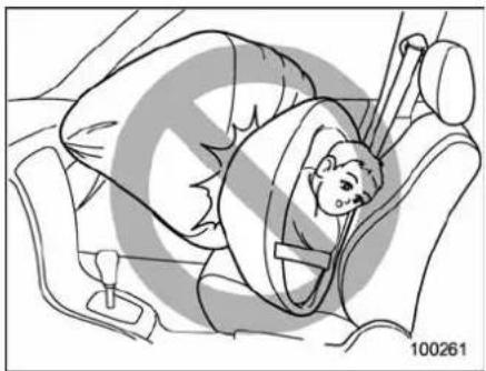
natural_image
Illustration of a person lying in a car seatbelt, no text or symbols present
WARNING
NEVERINSTALLAREARWARDFA- CINGCHILDSAFETYSEATINTHE FRONT SEAT. DOING SO RISKS SERIOUSINJURYORDEATHTO
THE CHILD BYPLACING THE CHILD'SHEADTOOCLOSETO THESRSAIRBAG.
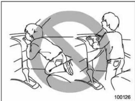
natural_image
Illustration of two people interacting near a table, one holding a child's head (no text or symbols)
WARNING
Neverallowachildtostandup,orto kneelonthefrontpassenger'sseat. The SRSairbagdeployswith considerableforceandcaninjureor evenkillthechild.
-CONTINUED-
1-50 Seat,seatbeltandSRSairbags
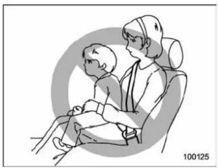
natural_image
Illustration of a child sitting on a chair facing an adult, with no visible text or symbols
WARNING
Neverholdachildonyourlaporin yourarms. The SRSairbagdeploys with considerable force and can injureorevenkill the child.
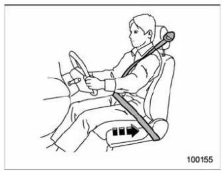
natural_image
Line drawing of a person seated in a car, wearing a steering wheel and belt (no text or symbols)
WARNING
The SRSairbagdeployswithconsiderablespeedandforce.OccupantswhoareoutofproperpositionwhentheSRSairbagdeployscouldsufferveryseriousinjuries.Because the SRSairbagneedsenoughspacefordeployment,thedrivershouldalwayssituprightandwellbackintheseatasfarfromthesteeringwheelaspracticalwhilestillmaintainingfullvehiclecontrolandthefrontpassengershouldmovetheseatasfarbackaspossibleandsituprightandwellbackintheseat.
Itisalsoimportanttowearyour
seatbelttohelpavoidinjuriesthat canresultwhentheSRSairbag contactsanoccupantnotinproper positionsuchasonethrowntoward thefrontofthevehicleduringpre-accidentbraking.
natural_image
Line drawing of a car interior showing steering wheel and dashboard (no text or symbols)
WARNING
Donotputanyobjectsoverthe steeringwheelpadanddashboard. IftheSRSfrontalairbagdeploys, thoseobjectscouldinterferewithits properoperationandcouldbepropelledinsidethevehicleandcause injury.
natural_image
Diagram showing a car interior with a person holding a sign, no readable text or symbols present
WARNING
Donotattachaccessoriestothe windshield,orfitanextra-widemirrorovertherearviewmirror.Ifthe SRSairbagdeploys,thoseobjects couldbecomeprojectilesthatcould seriouslyinjurevehicleoccupants.
▼Driver'sSRSfrontalairbag
Thedriver's SRSfrontalairbagusesa dualstageinflator. Theinflatoroperates in differentwaysdependingontheseverity of impact, backward-forwardadjustment of the driver'sseatposition and whether or nothe/sheiswearingtheseatbelt. Thebackward-forwardadjustment of the driver'sseatposition is monitored by the
driver'sseatpositionsensorunderthe driver'sseat.
Whetherornothedriveriswearingthe seatbeltismonitoredbytheseatbelt buckleswitch.
Observethefollowingprecautions.Failure todosomaycausetheseatbeltbuckle switchand/ortheseatpositionsensorto malfunction, preventingtheSUBARUadvancedfrontalairbagsystemfromfunctioningcorrectlyorcausingthesystemto fail.
- Donotplacearticles/metalobjector installanyaccessoryotherthanagenuine SUBARUaccessoryunderthedriver's seat.Donotallowtherearseatoccupant tokickthedriver'sseatorpushupits bottomsurfacewithhis/herfeet.
- Do notplaceamagnetnear the seatbeltbuckleorunderthedriver'sseat.
Iftheseatbeltbuckleswitchand/orthe driver'sseatpositionsensorhavefailed, theSRSairbagsystemwarninglightwill illuminate. Although the driver's SRS frontalairbagcandeployregardless of thebackward-forwardadjustmentofthe driver'sseatpositionevenwhenthe warninglightilluminates,havethesystem inspectedbyyourSUBARUdealerimmediatelyiftheSRSairbagsystemwarninglightilluminates.
NOTE
Thedriver's SRSsideairbag, SRS curtainairbag and seatbeltpretensioner are not controlled by the SUBARUadvancedfrontalairbagsystem.
▼Frontpassenger'sSRSfrontalair-bag
Thefrontpassenger's SRSfrontalairbag usesadualstageinflator. Theinflator operatesindifferentwaysdependingon theseverityofimpact.
Thetotalloadontheseatismonitored by theoccupantdetectionssystem'sweight sensorlocatedundertheseat.
Thesystemhasanothersensorthat monitorsthetensionofthefrontpassengerseatbelt. Usingthetotalseatloadand seatbelttensiondatafromthesensors, theoccupantdetectionsystemdetermines whetherthefrontpassenger'sSRSfrontal airbagshouldorshouldnotbeinflated.
Theoccupantdetectionsystemmaynot inflatethefrontpassenger'sSRSfrontal airbageevenwhenthedriver'sSRSfrontal airbagdeploys.Thisisnormal.
Observethefollowingprecautions.Failure todosomaypreventtheSUBARU advancedfrontalairbagsystemfrom functioningcorrectlyorcausethesystem tofail.
-CONTINUED-
1-52 Seat,seatbeltandSRSairbags
- Donotapplyanystrongimpacttothe frontpassenger'sseatsuchasbykicking.
- Donotspillliquidonthefrontpassenger'sseat. If liquidisspilled, wipeitoff immediately.
- Donotremoveordisassemblethefront passenger'sseat.
- Donotinstallanyaccessory(suchas anaudioamplifier)otherthanagenuine SUBARUaccessoryunderthefrontpassenger'sseat.
- Donotplaceanything(shoes,umbrella,etc.)underthefrontpassenger'sseat.
- Thefrontpassenger'sseatmustnotbe usedwiththeheadrestraintremoved.
- Donotleaveanyarticleincludinga childrestraintsystemonthefrontpassenger'sseatortheseatbelttongueand buckleengagedwhenyouleaveyour vehicle.
- Donotplaceamagnetnearthe seatbeltbuckleandtheseatbeltretractor.
If these seat belt buckles switch and/or front passenger's occupant detection system have failed, the SRSair bags system warning light will illuminate. Have the system inspected by your SUBARU deal-er immediately if the SRSair bags system warning light illuminates.
If your vehicle has sustained impact, this may affect the proper function of the
SUBARUadvancedfrontalairbagsystem. Have your vehicle inspected at your SUBARUdealer.
NOTE
Thefrontpassenger'sSRSsideairbag, SRScurtainairbag and seatbeltpretensionerarenotcontrolledbythe SUBARUadvancedfrontalairbagsystem.
▼Passenger'sfrontalairbagONand OFFindicators
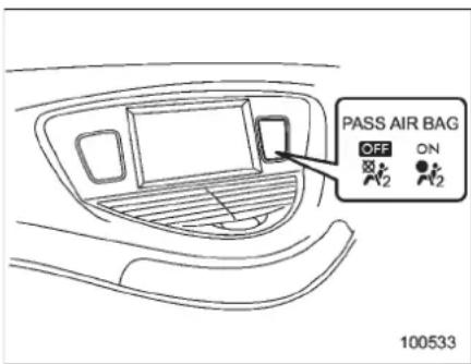
ON:Frontpassenger'sfrontalairbagON indicator
Frontpassenger'sfrontalairbagOFF indicator
Thefrontpassenger'sfrontalairbagON andOFFindicatorsshowyouthestatusof
thefrontpassenger'sSRSfrontalairbag. Theindicatorsarelocatedinthecenter portionoftheinstrumentpanel.
Whentheignitionswitchisturnedtothe "ON"position,boththeONandOFF indicatorsilluminatefor6secondsduring whichtimethesystemischecked.Followingthesystemcheck,bothindicatorsturn offor2seconds.Afterthat,oneofthe indicators illuminates depending onthe statusofthefrontpassenger'sSRSfrontal airbag determinedby theSUBARU advancedfrontalairbagsystemmonitoring. Ifthefrontpassenger'sSRSfrontalairbag isactivated,thepassenger'sfrontalairbag ONindicatorwillilluminatewhiletheOFF indicatorwillremainoff.
If the front passenger's SRS frontal airbag is deactivated, the passenger's frontal airbag ON indicator will remain off while the OFF indicator will illuminate.
Withtheignitionswitchturnedtothe"ON" position,ifboththeONandOFFindicatorssimultaneouslyremainilluminatedoroffevenafterthesystemcheckperiod,the systemis malfunctioning.Contactyour SUBARUdealer immediatelyforan inspection.
▼Conditionsinwhichfrontpassenger'sSRSfrontalairbagisnot activated
Thefrontpassenger'sSRSfrontalairbag will not be activated when any of the following conditions are met regarding the frontpassenger's seat.
- Theseatisempty.
- Theseatisequippedwitharearward facingchildrestraintsystemandaninfant isrestrainedwithit.(SeeWARNINGthat follows.)
- Theseatisequippedwithaforward facingchildrestraintsystemandasmall childisrestrainedwithit.(SeeWARNING thatfollows.)
- Theseatisequippedwithabooster seatandasmallchildisinthebooster seat.(SeeWARNINGthatfollows.)
- Theseatisrelievedoftheoccupant loadforatimeexceedingthepredeterminedmonitoringtimeperiod.
- Theseatisoccupiedbyachildwho hasoutgrownachildrestraintsystem (SeeWARNINGthatfollows.)orbya smalladult.
- Thefrontpassenger'soccupantdetectionsystemismalfunctioning.
WARNING
NEVERINSTALLAREARWARDFA- CINGCHILDSEATINTHEFRONT PASSENGER'SSEATEVENIFTHE FRONTPASSENGER'SSRSFRON- TALAIRBAGISDEACTIVATED.Be suretoinstallitinoneoftherear seatingpositionsrecommendedin thisOwner'sManualinacorrect manner.Also,itisstronglyrecom- mendedthatanyforwardfacing childseatorboosterseatbein- stalledinoneoftherearseating positionsrecommendedinthis Owner'sManual,andthateven childrenwhohaveoutgrownachild restraintsystembealsoseatedina REARseat. Thisis because children sittinginthefrontpassenger'sseat maybekilled orseverely injured shouldthefrontpassenger'sSRS frontalairbagdeploy.REARseats arethesafestplaceforchildren.
Whenthefrontpassenger'sseatisoccupiedbyachild,observethefollowing precautions. Failure to do so may increase theloadonthefrontpassenger'sseat, activating the front passenger's SRS frontalairbag even thoughthat seatis occupiedbyachild.
- Donotplaceanyarticleontheseat otherthanthechildoccupantandachild restraintsystem.
- Donotplacemorethanonechildon theseat.
- Donotinstallanyaccessorysuchasa tableorTV ontotheseatback.
- Donotstoreaheavyloadinthe seatbackpocket.
- Donotallowtherear/second-rowseat occupant to place his/her hands or legs on thefrontpassenger'sseatback,orallow him/hertopulltheseatback.
If the front passenger's frontal air bag ON indicator illuminates and the OFF indicator turn so even when an infant or a small child is in a child restraintsystem (including booster seat)
Turn the ignition switch to the "LOCK" position if the frontpassenger'sfrontal airbagONindicatorilluminatesandthe OFFindicatorturnsoff evenwhenan infantorasmallchildisinachildrestraint system(includingboosterseat).Remove the child restraint system from the seat. By referringtothechildrestraintmanufacturer'srecommendationsaswellasthe childrestraintsysteminstallationproceduresinthe"Childrestraintsystems"1-31sectioninthischapter,correctlyinstall
-CONTINUED -
1-54 Seat, seatbelt and SRSairbags
thechildrestraintsystem.Turntheignition switchtothe"ON"positionandmakesure thatthefrontpassenger'sfrontalairbag ONindicatorturnsoffandtheOFF indicatorilluminates.
If the ON indicator still remains illuminated while the OFF indicator turns off, takes the following actions.
- Ensure that no article is placed on the seat other than the child restraints system and the child occupant.
- Ensure that there is no article left in the seatback pocket.
IftheONindicatorstillremainsilluminated whiletheOFFindicatorturnsoffafter takingrelevantcorrectiveactionsdescribedabove,relocatethechildrestraint systemtooneoftherearseatingpositions recommendedinthisOwner'sManualand immediatelycontactyourSUBARUdealer foraninspection.
NOTE
Whenachildwhohasoutgrownnachild restraintsystemorasmalladultis seatedinthefrontpassenger'sseat, theSUBARUadvancedfrontalairbag systemmayormaynotactivatethe frontpassenger'sSRSfrontalairbag dependingontheoccupant'sseating posture.Ifthefrontpassenger'sSRS frontalairbagisactivated(theON indicatorremainsilluminatedwhile theOFFindicatorturnsoff),takethe followingactions.
- Ensure that no article is placed on theseatotherthantheoccupant. - Ensurethatthereisnoarticleleftin theseatbackpocket.
IftheONindicatorstillremainsilluminatedwhiletheOFFindicatorturnsoff despitethefactthattheactionsnoted abovehavebeentaken,seatthechild/smalladultintherearseatandimmediatelycontactyourSUBARUdealer foraninspection.Evenifthesystem haspassedthedealerinspection,itis recommendedthatonsubsequenttrips thechild/smalladultalwaystakethe rearseat.
Childrenwhohaveoutgrownachild restraint system should always wear the seatbeltirrespectiveofwhethertheairbag isdeactivatedoractivated.
▼Conditionsinwhichfrontpassenger'sSRSfrontalairbagisactivated
Thefrontpassenger'sSRSfrontalairbag willbeactivatedfordeploymentupon impact whenanyof thefollowingconditionsismetregardingthefrontpassenger'sseat.
- Whentheseatisoccupiedbyanadult.
- When a heavy article is placed on the seat.
Whenthefrontpassenger'sseatisoccupiedbyanadult,observethefollowing precautions.Failuretodosomaylessen theloadonthefrontpassenger'sseat, deactivatingthefrontpassenger'sSRS frontalairbagdespitethefactthattheseat isoccupiedbyanadult.
- Donotallowtherearseatoccupantto liftthefrontpassenger'sseatcushion usinghis/herfeet.
- Donotplaceanyarticleunderthefront passenger'sseat, or squeezeanyarticle from behind and undertheseat. This may liftheseat cushion.
- Donotsqueezeanyarticlebetween the front passenger's seat and side trim/pillar,doororcenterconsolebox.This maylifttheseatkushion.
If the passenger's frontal airbag OFF indicator illuminates and the ON indicator turn so feven when the front passenger's seatis occupied by an adult
This can be caused by the adult incorrectly sitting in the front passenger's seat. Turn theignitions switch to the "LOCK" position. Ask the front passenger to these seat back to the upright position, sit up
straightinthecenteroftheseatcushion, correctlyfastentheseatbelt,positionhis/herlegsoutforward,andadjusttheseatto therearmostposition.Turntheignition switchtothe"ON"position.IftheOFF indicatorremainsilluminatedwhiletheON indicatorremainsoff,takethefollowing actions.
- Turntheignitionswitchtothe"LOCK" position.
- Ensure that there are no articles, books, shoes, or other object strapped under these seat, at there are of these seat, or on the side of these seat.
- Next,turntheignitionswitchtothe "ON"positionandwait6secondstoallow thesystemtocompleteself-checking. Followingthesystemcheck,bothindicatorturnofffor2seconds.Now,theON indicatorshouldilluminatewhiletheOFF indicatorremainsoff.
IftheOFFindicatorstillremainsilluminatedwhiletheONindicatorremainsoff, asktheoccupanttomovetotherearseat andimmediatelycontactyourSUBARU dealerforaninspection.
▼Effectvehiclemodificationsmade forpersonswithdisabilitiesmay haveonSUBARUadvancedfrontal airbagsystemoperation(U.S.only)
Changingormovinganypartsofthefront seats,seatbelts,frontbumper,frontside frame,instrumentpanel,combinationmeter,steeringwheel,steeringcolumn,tire, suspensionorfloorpanel canaffect the operationoftheSUBARU advancedairbag system. If you have any questions, you may contact the following SUBARU distributors.
SubaruofAmerica,Inc.
CustomerDealerServicesDepartment P.O.Box6000
CherryHill.NJ08034-6000
1-800-SUBARU3(1-800-782-2783)
ServcoSubaruInc., dbaSubaruHawaii 2850PukoloaStreet, Suite202, Honolulu, HI96819
808-839-2273
Shen'sCorporationdbaPrestigeAutomobile
491, EastMarineDrive, Route1 Dededo, Guam
671-633-2698
TrebolMotors
P.O. Box 11204, San Juan, Puerto Rico 00910
787-793-2828
TherearecurrentlynoSUBARUdistributorsinanyotherU.S.territories.Ifyouare insuchanarea,pleasecontactthe
SUBARUdistributorordealerfromwhich youboughtyourvehicle.
1-56 Seat,seatbeltandSRSairbags
▼Operation
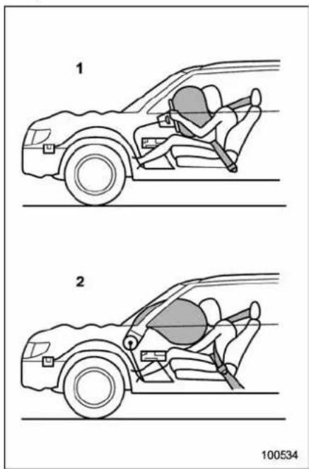
1) Driver'sside
2) Passenger'sside
The SRSairbag can function only when the ignition switch is in the "ON" position. The SUBARU advanced frontal airbag
systemisdesignedtodeterminethe activationordeactivationconditionofthe front passenger's SRS frontal airbag dependingonthetotalloadonthefront passenger'sseatmonitoredbythefront passenger'soccupantdetectionsystem weightsensor.Forthisreason,onlythe driver'sSRSfrontalairbagmaydeployin theeventofacollision,butthisdoesnot meanfailureofthesystem.
Ifthefrontsubsensorslocatedonboth sidesoftheradiatorpanelandtheimpact sensorsintheairbagcontrolmodule detectapredeterminedamountofforce duringafrontalcollision, thecontrol modulesendssignalstotheairbag module(s)(onlydriver'smoduleorboth driver'sandfrontpassenger'smodules) instructingthemodule(s)toinflatethe SRSfrontalairbag(s). Thedriver'sand frontpassenger'sSRSfrontalairbagsuse dualstageinflators. Thetwoinflatorsof eachairbagaretriggeredeithersequen-tiallyorsimultaneously, dependingonthe severityofimpact, backward-forwardad-justmentofthedriver'sseatpositionand fastening/unfasteningoftheseatbeltinthe caseofthedriver'sSRSfrontalairbagand dependingontheseverityofimpactand thetotalloadontheseatinthecaseofthe frontpassenger'sSRSfrontalairbag.
Afterdeployment, the SRSairbagimmediately startstodeflatesothatthedriver's visionisnotobstructed. Thetimerequired from detecting impact to the deflation of the SRSairbagafterdeployment is short-erthantheblinkofaney.
Whenonlythedriver'sSRSfrontalairbag deploysandboththedriver'sandfront passenger'sSRSfrontalairbagsdeploy, thedriver'sandfrontpassenger'sseatbelt pretensionersoperateatthesametime.
AlthoughitishighlyunlikelythattheSRS airbagwouldactivateinanon-accident situation,shoulditoccur,theSRSairbag willdeflatequickly,notobscuringvision andwillnotinterferewiththedriver's abilitytomaintaincontrolofthevehicle.
WhentheSRSairbagdeplays,asudden, fairlyloudinflationnoisewillbeheard and somesmokewillbereleased. These occurrencesareanormalresultof the deployment. Thissmokedoesnotindicate afireinthevehicle.

CAUTION
DonottouchtheSRSairbagsystem componentsaroundthesteering wheelanddashboardwithbare handsrightafterdeployment.Doing so can cause burns because the
componentscanbeveryhotasa resultofdeployment.
Thedriver'sSRSfrontalairbagandfront passenger'sSRSfrontalairbagaredesignedtodeployintheeventofan accidentinvolvingamoderatetosevere frontalcollision.Itisbasicallynotdesignedtodeployinlesserfrontalimpactsbecausethenecessaryprotectioncanbe achievedbytheseatbeltalone.Also,they arebasicallynotdesignedtodeployin sideorrearimpactsorinrolloveraccidentsbecausedeploymentofonlythe driver'sSRSfrontalairbagorbothdriver's andfrontpassenger'sSRSfrontalairbags wouldnothelptheoccupantinthose situations.Thedriver'sandfrontpassenger'sSRSfrontalairbagsaredesignedto functiononaone-time-onlybasis.
SRSairbagdeploymentdependsonthe levelofforceexperiencedinthepassengercompartmentduringacollision.That leveldiffersfromonetypeofcollisiononto another, anditmayhavenobearingon thevisibledamagedonetothevehicle itself.
Examplesofaccidentsinwhichthe driver's/driver'sandfrontpassenger'sSRSfrontalairbag(s)willmost likelydeploy.
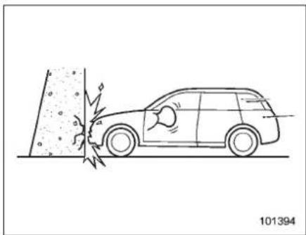
natural_image
Line drawing of a car approaching a surface with a broken edge, showing impact or damage (no text or symbols)Ahead-oncollisionagainstathickconcretewallatavehiclespeedof12to19 mph(20to30km/h)orhigheractivates onlythedriver'sSRSfrontalairbagorboth driver'sandfrontpassenger'sSRSfrontal airbags. Theairbag(s)willalsobeeactivatedwhenthevehicleisexposedoa frontalimpactsimilarinfashionand magnitudeto the collision described above.
Examplesofthetypesofaccidents inwhichitispossiblethatthe driver's/driver'sandfrontpassenger'sSRSfrontalairbag(s)willdeploy.
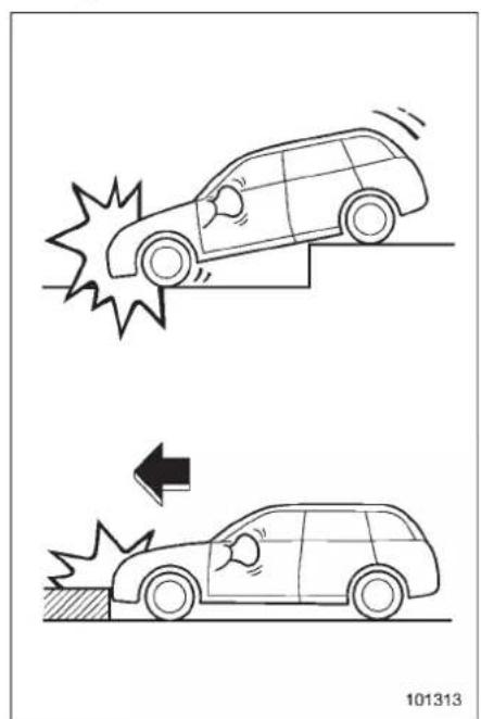
natural_image
Two cartoon-style illustrations of a car collision with an arrow indicating impact (no text or symbols)Theonlythedriver'sSRSfrontalairbagor
-CONTINUED-
1-58 Seat,seatbeltandSRSairbags
bothdriver'sandfrontpassenger'sSRS frontalairbagsmaybeactivatedwhenthe vehiclesustainsahardimpactinthe undercarriageareafromtheroadsurface (suchaswhenthevehicleplungesintoa deepditch,isseverelyimpactedor knockedhardagainstanobstacleonthe roadsuchasacurb).
Examples of the types of accidents in which deployment of the driver's/driver's andfrontpassenger'sSRSfrontalairbag(s)isunlikelytooccur.
1
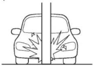
natural_image
Diagram of a car divided vertically with arrows indicating impact or damage, no text or symbols present2
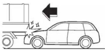
natural_image
Diagram of a truck with a car and an arrow indicating direction (no text or symbols)3
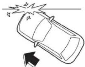
natural_image
Simple line drawing of a car with an explosion and arrow indicating upward motion (no text or symbols)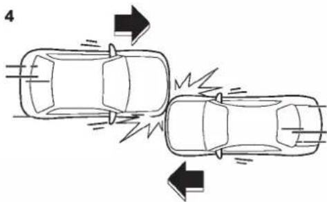
natural_image
Top-down line drawing of two cars with arrows indicating collision or damage, no text or symbols present101314
1) The vehicle strikes an object, such as telephone pole or sign pole.
2)Thevehicleslidesundertheloadbedof atruck.
3) The vehicles sustain an oblique offset frontal impact.
4) The vehicles sustain an offset frontal collision.
Therearemany types of collisions which might not necessarily require deployment of driver's /driver's sandfrontpassenger's SRS frontalairbag(s). In the event of accidents likethose illustrated, the driver's /driver's sandfrontpassenger's SRS frontalairbag(s) may not deploy depending on the level of accident forces involved.
1-60 Seat,seatbeltandSRSairbags
Examplesofthetypesofaccidents in which the driver's/driver's and frontpassenger'sSRSfrontal airbag(s)willbasicallynotdeploy.
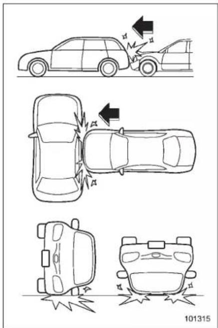
Thedriver'sandfrontpassenger'sSRS frontalairbagsaredesignedbasicallynot
todeployifthevehicleisstruckfromthe sideorfrombehind,orifitrollsontoits sideorroof,orifitisinvolvedinalow-speedfrontalcollision.
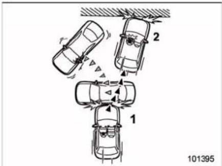
1) Firstimpact 2) Secondimpact
Inanaccidentwherethevehicleis impactedmorethanonce,thedriver's and/orfrontpassenger'sSRSfrontal airbag(s)willdeployonlyonceonthefirst impact.
Example: In the case of a double collision, first with another vehicle, then against a concrete wall in immediate succession, once either or both of the driver's and front passenger's SRS frontal air bags is/are activated on the first impact, it/they will not be activated on the second impact.
■ SRSsideairbagandSRS curtainairbag
The SRSsideairbagisstoredinthedoor sideofeach frontseatseatback, which bearsan "SRSAIRBAG" label.
In a moderate to severe side impact collision, the SRSsideairbagonthe impactedsideofthevehicledeploys between the occupant and the door panel and supplements theseatbeltbyreducing the impact to the occupant's chest and waist. The SRSsideairbagoperates only for frontseatoccupants.
The SRScurtainairbagoneachside of thecabinisstoredintheroof side (betweenthefrontpillarandapointover therearseat). An "SRSAIRBAG" markis located at the top of each center pillar.
In a moderate to severe side impact collision, the SRScurtainairbag onthe impactedsideofthevehicledeploys between the occupant and the side window and supplements theseatbelt by reducing the impact on the occupant's head.
Inarollover, SRScurtainairbagsonboth sidesofthevehicledeploybetweenthe occupantandthesidewindowandsupplementtheseatbeltbyreducingthe impacttotheoccupant'shead.
In7-seatermodels, the SRScurtain
airbagdoesnotoperateforthird-rowseat occupants.

WARNING
The SRS side airbag and SRS curtain airbag are designed as only as supplement to the primary protection provided by these seat belt. They donot do away with the need to fastenseat belts. It is also important to wear your seat belt to help avoid injuries that can result when an occupant is not seated in a proper upright position.
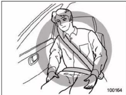
natural_image
Illustration of a person sitting in a car seatbelt, no text or symbols present
WARNING
•Donotsitorleanunnecessarily
closetoeitherfrontdoor.The SRSsideairbagisstoredinboth frontseatseatbacksnexttothe door,anditprovidesprotection bydeployingrapidly(fasterthan theblinkofaneye)intheeventof asideimpactcollision.However, the force of SRS deploymentmaycauseinjuries ifyourheaderotherpartsofthe bodyaretooclosetotheSRS sideairbag.
- Sinceyourvehicleisequipped withSRScurtainairbags,donot sitorleanunnecessarilycloseto thefrontorreardooroneither side.Also,donotputyourhead, armsandhandsoutofthewin- dow.TheSRScurtainairbagon eachsideofthecabinisstoredin theroofside(betweenthefront pillarandapointovertherear seat),anditprovidesprotection bydeployingrapidly(fasterthan theblinkofaneye)intheeventof asideimpactorarollover.How- ever,theforceofitsdeployment maycauseinjuriesifyourheadis tooclosetoit.
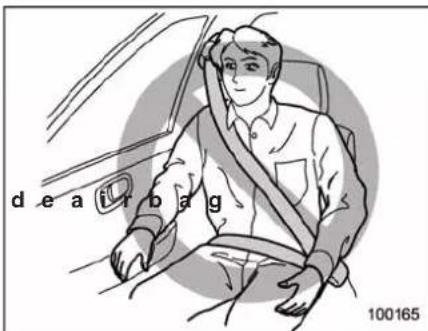

WARNING
Donotrestyourarmoneitherfront doororitsinternaltrim.Itcouldbe injuredintheeventofSRSside airbagdeployment.
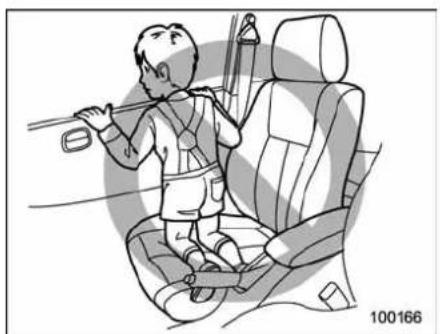
natural_image
Illustration of a child sitting in a car seat, holding a bicycle (no text or symbols present)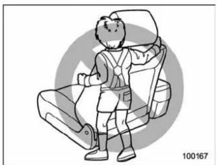
natural_image
Illustration of a person sitting in a car seat with backpacks, no text or symbols present
WARNING
- Neverallowachildtokneelon thefrontpassenger'sseatfacing thesidewindowortowraphis/herarmsaroundthefrontseat
seatback.Intheeventofan accident,theforceoftheSRS sideairbagdeploymentcould injurethechildseriouslybecausehis/herheaderarmsor otherpartsofthebodyaretoo closetotheSRSsideairbag. Since your vehicle is also equippedwithafrontpassenger'sSRSfrontalairbag,children aged12 and undershould be placedinarearseatanywayand should be properly restrained at alltimes.
- Neverallowachildtokneelon anypassenger's seatfacingthe sidewindoworputtheirhead, armsandhandsoutofthewindow. Inthe eventof anaccident, theforceoftheSRScurtain airbagdeploymentcouldinjure thechildseriouslybecausehis/her headis closeto theSRS curtainairbag.
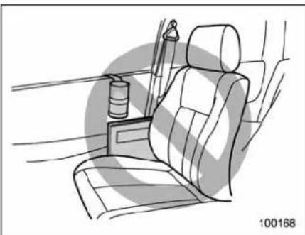
natural_image
Line drawing of a car seat with rear seats and a side-mounted device (no text or symbols)
WARNING
- Do not attach accessories to the doortrimorneareitherSRSside airbagsanddonotplaceobjects neartheSRSsideairbags.Inthe eventoftheSRSside airbag deployment,theycouldbeprolleddangerouslytowardthe vehicle's occupants and cause injuries.
- Donotattachahands-freemicro-phoneoranyother accessoryto afrontpillar,acenterpillar,arear pillar,thewindshield, asidewin-dow, an assist grip, or any other cabinsurfacethatwouldbenear adeployingSRScurtainairbag.
Ahands-freemicrophone or otheraccessoryinsuchalocationcouldbepropelledthrough thecabinwithgreatforcebythe curtainairbag,oritcouldprevent correctdeploymentofthecurtain airbag.Ineithercase,theresult couldbeseriousinjuries.
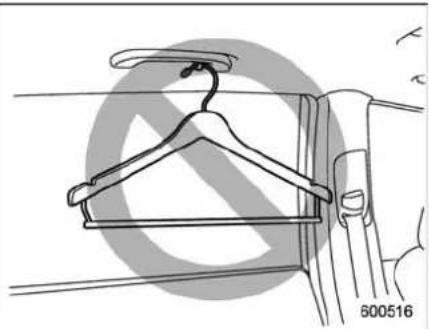
natural_image
Line drawing of a hanger with handle and jacket, showing front view and side view (no text or symbols)
WARNING
Donothangcoathangersorother hardorpointedobjectsonthecoat hooks. If such items were hanging on the coathooks during deployment of the SRS curtain airbags, they could cause serious injuries by coming off the coathooks and being thrown through the cabinor by
preventingdeploymentofthecur- tainairbags.
Beforehangingclothingonthecoat hooks, makesuretherearenosharp objectsinthepockets. Hangclothingdirectlyonthecoathookswithoutusinghangers.
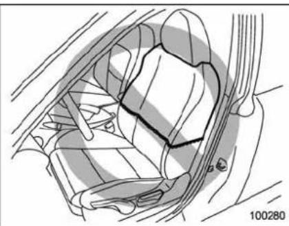
natural_image
Technical illustration of a car interior showing steering wheel and dashboard (no text or symbols)
WARNING
Donotputanykindofcoveror clothesorotherobjectsovereither frontseatbackanddonotattach labelsorstickerstothefrontseat surfaceonorneartheSRSside airbag.Theycouldpreventproper deploymentoftheSRSsideairbag, reducingprotectionavailabletothe
frontseat'soccupant.
▼Operation
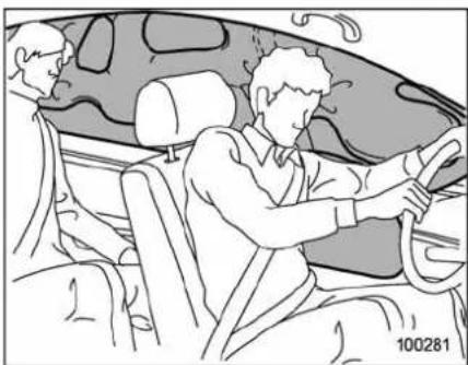
natural_image
Line drawing of a person inside a car, seated and standing with hands on steering wheel (no text or symbols)The SRSsideairbag and SRScurtain airbag can function only when the ignition switch is in the "ON" position.
The driver's and front passenger's SRS sideairbagsandSRScurtainairbags deployindependentlyofeachotherbe- causeeachhasitsownimpactsensor. Therefore,theymaynotbothdeployinthe sameaccident.Also,theSRSsideairbag andSRScurtainairbagdeploysindependentlyofthedriver'sandfrontpassen- ger'sSRSfrontalairbagsinthesteering wheelandinstrumentpanel.
Animpactsensor, which senses impact
-CONTINUED-
1-64 Seat, seatbelt and SRSairbags
force,islocatedineachoftheleftand rightcenterpillarsandrearwheelhouses. Anotherimpactsensor,whichalsosenses impactforce,islocatedundertherear centerseat(5-seatermodels)/underthe second-rowcenterseat(7-seatermodels). Inaddition,arolloversensorislocated insidetheairbagcontrolmodule.
Ifoneofthecenterpillarimpactsensors andtheimpactsensorthatislocated undertherearcenterseat(5-seater models)/underthesecond-rowcenterseat (7-seatermodels)togethersenseanim-pactforceaboveapredeterminedlevelin asidecollision,thecontrolmodulecauses boththeSRSsideairbagandcurtain airbagontheimpactedsidetoinflate regardlessofwhethertherearwheel houseimpactsensoronthesameside sensesanimpact.Atthistime,thedriver's andfrontpassenger'sseatbeltpretensionersalsooperateatthesametime.
Ifoneoftherearwheelhouseimpact sensorsandtheimpactsensorthatis locatedundertherearcenterseat(5-seatermodels)/underthesecond-row centerseat(7-seatermodels)together senseanimpactforceaboveapredeterminedlevelinasidecollision,thecontrol modulecausesonlytheSRScurtain airbagontheimpactedsidetoinflate.
Iftherolloversensordetectsrolloverofthe vehicle,thecontrolmoduleinflatesthe SRScurtainairbags.Atthistime,the driver'sandfrontpassenger'sseatbelt pretensionersalsooperateatthesame time.
Afterdeployment, the SRSsideairbag immediately startstodeflate. Thetime required from detection of an impact to deflation of an SRS sideair bag after deployment is shorter than the blink of an eye.
The SRScurtainairbagremainsinflated forwhilefollowingdeploymentthen slowlydeflates.
The SRSsideairbag and SRScurtain airbag deploy even when no one occupies these at on the side on which an impact is applied.
WhentheSRSsideairbagandSRS curtainairbagdeploy,asudden,fairlyloud inflationnoisewillbeheardandsome smokewillbereleased.Theseoccurrencesareanormalresultofthedeployment.Thissmokedoesnotindicateafire inthevehicle.

CAUTION
DonottouchtheSRSsideairbag systemcomponentsaroundthe
frontseatseatbackwithbarehands rightafterdeployment.Doingsocan causeburnsbecausethecomponentscanbeveryhotasaresultof deployment.
Afterdeployment, donottouchany partofthe SRScurtain airbag system(fromthefrontpillartothe partoftheroofsideovertherear seat). Doingsocancauseburns because the components can be veryhotasaresultofdeployment.
The SRSsideairbag and SRScurtain airbag are designed to deploy in the event of an accident involving a moderate to severe impact collision. Also, in the case of a rollover, the SRScurtain airbag deploys. They are basically not designed to deploy in a less severe impact. Also, they are basically not designed to deploy in frontal or greater impacts because SRS side airbag and SRScurtain airbag deployment would not help the occupant in those situations.
EachSRSsideairbagandSRScurtain airbagaredesignedtofunctiononaone-time-onlybasis.
SRSsideairbagandSRScurtainairbag deploymentdependonthelevelofforce experiencedinthepassengercompart-
mentduringasideimpactcollision. That leveldiffersfromonetypeofcollisiononto another, and it may havenobearing on the visible damagedonthe vehicle itself. Also, the SRScurtainairbagde- ploysdependingonthe vehicle's position and inclination at the time of the rollover.
Exampleofthetypeofaccidentin whichtheSRSsideairbagwillmost likelydeploy.
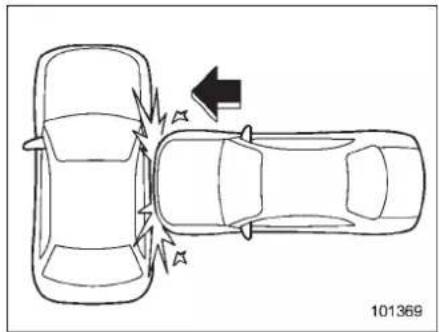
natural_image
Top-down diagram of a car collision with an arrow indicating direction (no text or symbols)Aseveresideimpactnearthefrontseat activatestheSRSsideairbag.
1-66 Seat,seatbeltandSRSairbags
ExamplesofthetypesofaccidentsinwhichtheSRScurtainairbagwillmost likelydeploy.
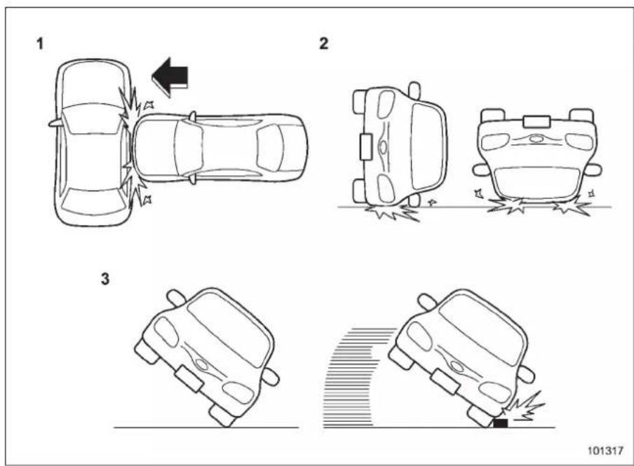
101317
1) Asevereside impact near the front seat or therearse at activate the SRS curtain airbag.
2)Thevehiclerollsontoitssideortheroof.
3) If the angle of vehicle tip-up is marginal or if the skidding vehicle's stireshita curbstonelaterally.
ExamplesofthetypesofaccidentsinwhichitispossiblethattheSRSside airbagandtheSRScurtainairbagwilldeploy.
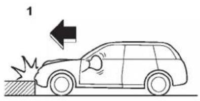
natural_image
Line drawing of a car with a broken hood and exhaust flame, showing no text or symbols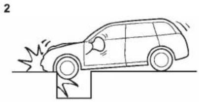
natural_image
Line drawing of a car on a surface with motion lines indicating speed or impact (no text or symbols)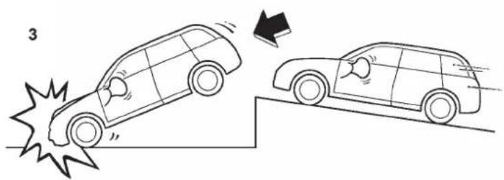
natural_image
Illustration of two cars on a track with a collision impact, no text or symbols present1) Hittingacurb, edgeofpavementorhard surface
2) Falling into or jumping over a deephole
3)Landinghardorvehiclefalling
ItispossiblethattheSRSsideandcurtain airbagswilldeployifaseriousimpact occurstotheundersideofyourvehicle.
Some examples are shown in the illustration.
1-68 Seat,seatbeltandSRSairbags
ExamplesofthetypesofaccidentsinwhichtheSRSsideairbagisunlikelyto deploy.
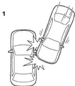
natural_image
Simple line drawing of a car collision with an explosion (no text or symbols)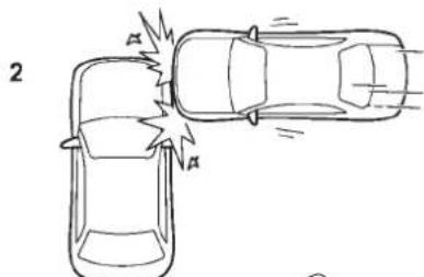
natural_image
Top-down line drawing of two cars with cracks and motion lines, no text or symbols present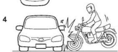
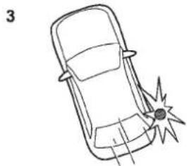
natural_image
Line drawing of a car with a broken head and a lightning bolt striking the side (no text or symbols)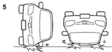
natural_image
Line drawing of two car bodies with visible wheels and structural details (no text or symbols)101319
1) The vehicle is involved in an oblique side-on impact.
2) The vehicle is involved in outside on impact in an area outside the vicinity of the passenger compartment.
3) The vehicle strikes a telephone pole or similar object.
4) The vehicle is involved in side-on impact from motorcycle.
5)Thevehiclerollsontoitssideortheroof.
Therearemanytypesofcollisionswhich mightnotnecessarilyrequireSRSside airbagdeployment.Intheeventofaccidentslikethoseillustrated,theSRSside airbagmaynotdeploydependingonthe levelofaccidentforcesinvolved.
ExamplesofthetypesofaccidentsinwhichtheSRScurtainairbagisunlikely todeploy.
1
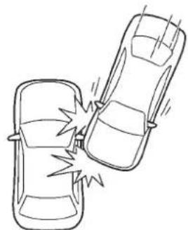
natural_image
Line drawing of two cars crashing with a large explosion (no text or symbols)2
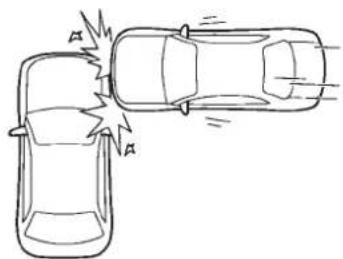
natural_image
Line drawing of two cars in a collision, showing impact with no text or symbols3
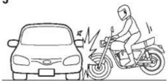
natural_image
Line drawing of a person riding a motorbike next to a car, with no text or symbols present.101412
1) The vehicle is involved in an oblique side-on impact.
2) The vehicle is involved in outside on impact in an area outside the vicinity of the passenger compartment.
3) The vehicle is involved in side-on impact from motorcycle.
Therearemanytypesofcollisionswhich mightnotnecessarilyrequireSRScurtain airbagdeployment.Intheeventofaccidentslikethoseillustrated,theSRScurtainairbagmaynotdeploydepending onthelevelofaccidentforcesinvolved.
1-70 Seat,seatbeltandSRSairbags
Examplesofthetypesofaccidents inwhichtheSRSsideairbagand SRScurtainairbagwillbasicallynot deploy.
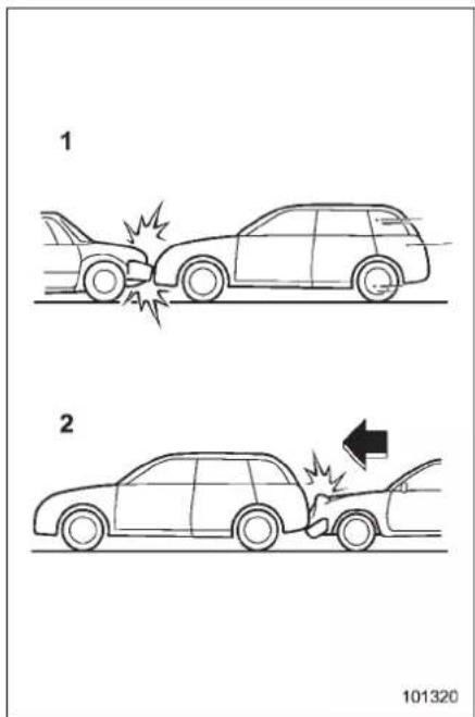
1) The vehicle is involved in frontal collision with another vehicle (moving or stationary).
2)Thevehicleisstruckfrombehind.
TheSRSsideairbagandSRScurtain airbagarebasicallynotdesignedto deployifthevehicleisinvolvedinafrontal collisionorisstruckfrombehind.Examplesofsuchaccidentsareillustrated.
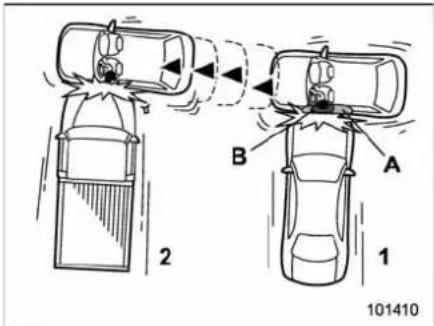
1) Firstimpact
2)Secondimpact
A) SRScurtainairbag
B) SRSsideairbag
Inanaccidentwherethevehicleisstruck fromthesidemorethanonce,theSRS sideairbagandSRScurtainairbagdeploy onlyonceonthefirstimpact.
Example: In the case of a doubleside impact collision, first with one vehicle and immediately followed by another from the samedirection, on the SRS side airbag
and SRScurtainairbagareactivated on the first impact, they will not be activated on the second.
Exampleofthetypeofaccidentin whichtheSRScurtainairbagwill basicallynotdeploy.
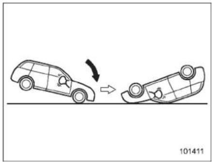
natural_image
Diagram showing a car moving on a road with an arrow indicating direction (no text or symbols)The SRScurtainairbagsarenotbasically designedtodeployifthevehiclepitches endoverend.
SRSairbagsystemmonitors
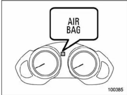
Adiagnosticsystemcontinuallymonitors thereadinessoftheSRSairbagsystem (includingfrontseatbeltpretensioners) whilethevehicleisbeingdriven.The SRSairbagsystemwarninglight"AIR- BAG"willshownormalsystemoperation bylightingforapproximately6seconds whentheignitionswitchisturnedtothe "ON"position.
The following components are monitored by the indicator.
●Frontsubsensor(right-handside)
●Frontsubsensor(left-handside)
●Airbagcontrolmodule(includingimpactandrolloversensors)
- Frontalairbagmodule(driver'sside)
- Frontalairbagmodule(frontpassen-
ger'sside)
- Sideairbagsensor(centerpillarrighthandside)
- Sideairbagsensor(centerpillarleft-handside)
- Sideairbagmodule(driver'sside)
- Sideairbagmodule(frontpassenger's side)
- Curtainairbagsensor(rearwheel houseright-handside)
- Curtainairbagsensor(rearwheel houseleft-handside)
●Curtainairbagmodule(right-handside)
- Curtainairbagmodule(left-handside)
- Satellitesafingsensor(undertherear centerseat[5-seatermodels]/underthe second-rowcenterseat[7-seatermodels])
- Seatbeltpretensioner(driver'sside)
- Seatbeltpretensioner(frontpassenger'sside)
- Seatbeltbuckleswitch(driver'sside)
- Seatbeltbuckleswitch(frontpassenger'sside)
- Driver'sseatpositionsensor
- Front passenger's seatbelt tension sensor
- Frontpassenger'soccupantdetection systemweightsensor
- Frontpassenger'soccupantdetection controlmodule
- Frontpassenger'sfrontalairbagON andOFFindicator
- Allrelatedwiring

WARNING
If the warning light exhibits any of the following conditions, ther may be a malfunction in these seat belt pretensioners and/or SRSairbag system. Immediately take your vehicle to your nearest SUBARU dealer to have the system checked. Unless checked and properly repaired, the seat belt pretensioners and/or SRS airbags will operate improperly (e.g. SRSairbags may inflate in every minor collision or not inflate in severe collision), which may increase risk of injury.
- Flashingorflickeringofthewarninglight
- Noilluminationofthewarning lightwhentheignitionswitchis firstturnedtothe"ON"position
●Continuousilluminationofthe warninglight - Illuminationofthewarninglight whiledriving
1-72 Seat,seatbeltandSRSairbags
■ SRSairbagsystemservicing

WARNING
- Whendiscardinganairbagmoduleorscrappingtheentirevehicledamagedbyacollision,consultyourSUBARUdealer.
- The SRSairbaghasnouser-serviceableparts.Donotuse electricaltestequipmentonany circuitrelatedtotheSRSairbag system.Forrequiredservicingof theSRSairbag,consultyour nearestSUBARUdealer.Tamperingwithordisconnectingthe system'swiringcouldresultin accidentalinflationoftheSRS airbagorcouldmakethesystem inoperative,whichmayresultin seriousinjury.

CAUTION
Ifyouneedserviceorrepairinareas indicatedinthefollowinglist,have theworkperformedbyanauthor- izedSUBARUdealer.TheSRSair- bagcontrolmodule,impactsensors andairbagmodulesarestoredin theseareas.
•Underthecenterconsole
•Insideeachfrontfender
•Steeringwheelandcolumnand nearbyareas
- Topofthedashboardonfront passenger'sside andnearby areas
●Eachfrontseatandnearbyarea
- Insideeachcenterpillar
•Ineachroofside(fromthefront pillartoapointovertherearseat)
- Between therearseat cushion and rear wheel house one each side
●Undertherearcenterseat(5-seatermodels)/underthesecond-rowcenterseat(7-seater models)
IntheeventthattheSRSairbagis deployed, replacementofthesystem shouldbeperformedonlybyanauthorizedSUBARUdealer.WhenthecomponentsoftheSRSairbagsystemare replaced,useonlygenuineSUBARU parts.
NOTE
Inthefollowingcases,contactyour SUBARUdealerassoonaspossible.
- Thefrontpartofthevehiclewas involvedinanaccidentinwhichonly thedriver'sSRSfrontalairbagorboth driver's and front passenger's SRS frontalairbagsdidnotdeploy.
- Thepadofthesteeringwheel,the coveroverthefrontpassenger'sSRS frontalairbag,oreitherroofside(from thefrontpillartoapointovertherear seat)isscratched,cracked,orotherwisedamaged.
- Centerpillar, rearwheelhouseor rearfloorpan, oranareanearthese parts, was involved in an accident in which the SRS side airbag and SRS curtain airbag did not deploy.
- Thefabricorleatherofeitherfront seatbackiscut,frayed,orotherwise damaged.
- Therearpartofthevehiclewas involvedinanaccidentinwhichno SRSairbagwasdeployed.
■Precautionsagainstvehicle modification

WARNING
To avoid accidental activation of the system or rendering the system in operative, which may result in serious injury, nomodifications
shouldbemadetoanycomponents orwiringoftheSRSairbagsystem. This includes following modifications.
•Installationofcustomsteering wheels
- Attachmentofadditionaltrim materialstothedashboard
•Installationofcustomseats
- Replacementofseatfabricor leather
•Installationofadditionalalfabricor leatheronthefrontseat
- Attachmentofahands-freemicrophoneoranyotheraccessory toafrontpillar,acenterpillar,a rearpillar,thewindshield,aside window,anassistgrip,orany othercabinsurfacethatwouldbe nearadeployingSRScurtain airbag.
• Installationofadditionalelectrical/electronicequipmentsuchas amobiletwo-wayradioonor nearthe SRSairbagsystem componentsand/orwiringisnot advisable. Thiscouldinterfere withproperoperationofthe SRSairbagsystem.
CAUTION
Donotperformanyofthefollowing modifications.Suchmodifications caninterferewithproperoperation oftheSRSairbagsystem.
- Attachmentofanyequipment (bushbar,winches,snowplow, skidplate,etc.)otherthangenuineSUBARUaccessoryparts.
-Modificationofthesuspension systemorfrontendstructure. - Installation of a tire of different sizeandconstructionfromthe tiresspecifiedonthevehicle placard attached to the driver's doorpillarorspecifiedforindividualvehiclemodelsinthisOwner'sManual.
- Attachmentofanyequipment (sidestepsorsidesillprotectors, etc.)otherthangenuineSUBARU accessorypartstothesidebody.
AlwaysconsultyourSUBARUdealer if youwanttoinstallanyaccessorypartson yourvehicle.
| -1.5 | -1.5 | -1.5 | -1.5 |
Keys and doors
Keys....2-2
Keynumberplate....2-2
Immobilizer....2-3
SecurityIDplate....2-3
Securityindicatorlight....2-4
Keyreplacement....2-4
Doorlocks....2-5
Lockingandunlockingfromtheoutside....2-5
Lockingandunlockingfromtheinside....2-5
Batterydrainagepreventionfunction....2-6
Powerdoorlockingswitches....2-7
Keylock-inpreventionfunction....2-8
Remotekeylessentrysystem....2-8
Lockingthedoors....2-9
Unlockingthedoors....2-10
Unlockingthereargate....2-10
Illuminatedentry....2-10
Vehiclefinderfunction....2-10
Soundingapanicalarm....2-11
Selectingaudiblesignaloperation....2-11
Replacingthebattery....2-11
Replacinglosttransmitters.... 2-12
Alarm system 2-16
Systemoperation.... 2-16
Activatinganddeactivatingthealarmsystem..... 2-16
If you have accidentally triggered the alarm system 2-17
Armingthesystem.... 2-17
Disarmingthesystem.... 2-18
Valet mode 2-18
Passive arming.... 2-19
Trippedsensoridentification.... 2-20
Shocksensors(dealeroption).... 2-20
Childsafetylocks....2-21
Windows.... 2-21
Powerwindows.... 2-21
Rear gate 2-24
Moonroof (if equipped).... 2-25
Tilt function 2-26
Sliding function 2-26
Anti-entrapmentfunction.... 2-26
Sun shade 2-27
2-2Keysanddoors
Keys
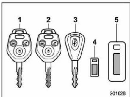
1) Masterkey
2)Submasterkey
3) Valetkey
4)Keynumberplate
5)SecurityIDplate
Threetypesofkeysareprovidedforyour vehicle.
Masterkey, submasterkey and valetkey.
Themasterkeyandsubmasterkeyfitall locksonyourvehicle.
- Ignitionswitch
- Driver'sdoor
Glovebox
Thevaletkeyfitsonlytheignitionswitch anddoorlocks.Youcankeeptheglove
boxlockedwhenyouleaveyourvehicle andvaletkeyataparkingfacility.
CAUTION
Donotattachalargekeyholderor keycasetoeitherkey.lfitbangs againstyourkneeswhileyouare driving,itcouldturntheignition switchfromthe"ON"positiontothe "Acc" or "LOCK" position,thereby stoppingtheengine.
■Keynumberplate
1
2
200701
1) Keynumberplate
2)SecurityIDplate
Thekeynumberisstampedonthekey numberplateattachedtothekeyset. Writedownthekeynumberandkeepitin anothersafeplace, notinthevehicle. This numberisneededtomakeareplacement key if you lose your key or lock it inside the vehicle.
Forinformationonmakingreplacement keysformodels withthe immobilizer system,referto"SecurityIDplate" 2-3.
Immobilizer
Theimmobilizersystemisdesignedto preventanunauthorizedpersonfrom startingtheengine.Onlykeysregistered withyourvehicle'simmobilizersystemcan beusedtooperateyourvehicle.Evenif anunregisteredkeyfitsintotheignition switchandcanbeturnedtothe"START" position,theenginewillautomaticallystop afterseveralseconds.
Eachimmobilizerkeycontainsatransponderinwhichthekey'slDcodeis stored.Whenakeyisinsertedintothe ignitionswitchandturnedtothe"ON" position,thetranspondertransmitsthe key'slDcodetotheimmobilizersystem's receiver.IfthetransmittedIDcode matchesthelDcoderegisteredinthe immobilizersystem,thesystemallowsthe enginetobestarted.SincethelDcodeis transmittedandacteduponalmostinstantly,theimmobilizersystemdoesnot impedenormalstartingoftheengine. Iftheenginedoesnotstart,pulloutthe keyoncebeforetryingagain.Referto "Ignitionswitch" 3-3.
This device complies with Part 15 of the FCC Rules and with RSS-210 of Industry Canada. Operation is subject to the following two conditions: (1) This
devicemaynotcauseharmfulinterference, and (2) this devicemust acceptanyinterferencereceived, includinginterferencethatmaycause undesiredoperation.
Changes or modifications not expressly approved by the party responsible for compliance could avoid the user's authority to operate the equipment.
NOTE
Toprotectyourvehiclefromtheft, pleasepaycloseattentiontothefollowingsecurityprecautions.
- Neverleaveyourvehicleunattended withitskeysinside.
- Beforeleavingyourvehicle,closeall windowsandlockthedoorsandrear gate.
- Donotleavesparekeysorany recordofyourkeynumberinthe vehicle.

CAUTION
- Donotplacethekeyunderdirect sunlightoranywhereitmay becomehot.
- Donotgetthekeywet.Ifthekey getswet,wipeitdrywithacloth immediately.
■SecurityIDplate
1
2
200701
1) Keynumberplate
2) SecurityIDplate
Thesecurity|Disstampedonthesecurity IDplateattachedtothekeyset.Write downthesecurity|Dandkeepitin anothersafeplace,notinthevehicle. Thisnumberisneededtomakeareplacementkeyifyouloseyourkeyorlockit insidethevehicle.
This number is also needed for replacement repair of the engine control unit, integrated unit, and combination meter.
-CONTINUED-
2-4Keysanddoors
■Securityindicatorlight
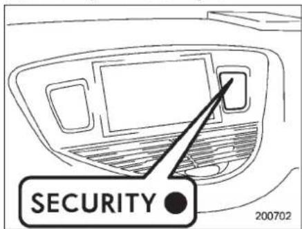
Thesecurityindicatorlightdeterspotential thievesbyindicatingthatthevehicleis equippedwithanimmobilizersystem.It beginsflashingapproximately60seconds aftertheignitionswitchisturnedfromthe "ON" position to the "Acc" or "LOCK" positionorimmediatelyafterthekeyis pulledout.
If these security indicator light does not flash, the immobilizersystem may be malfunctioning. If this occurs, contact your SUBARU dealer as soon as possible.
Incaseanunauthorizedkeyisused(e.g. animitationkey), thesecurityindicator lightilluminates.
NOTE
Evenifthesecurityindicatorlight flashesirregularlyoritsfuseblows (thelightdoesnotflashifitsfuseis blown),theimmobilizersystemwill functionnormally.
■Keyreplacement
YourkeynumberplateandsecurityID platewillberequiredifyoueverneedareplacementkeymade.Anynewkeymust beregisteredforusewithyourvehicle's immobilizersystembeforeitcanbeused. Uptofourkeyscanberegisteredforuse withonevehicle.
Forsecurity, allthekeysregistered with your vehicle'simmobilizersystemwill have their ID codeserased and re-registered when a new key is made. Therefore, allof your vehicle's keysmust be presented when anewkeyisregistered. Any key that is not a registered when anewkeyismadecannot be used after the other keysarere-registered. For information on replacement keys and on theregistration of keys with your immobilizersystem, contact your SUBARU dealer.
NOTE
Avehiclethatisequippedwiththe remoteenginestartsystemasadealer
optioncanregisteruptothreekeysfor usewithonevehicle.
Doorlocks
■Lockingandunlockingfrom theoutside
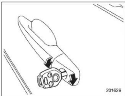
natural_image
Line drawing of a mechanical tool with arrows indicating movement or force, no text or symbols presentTolockthedriver'sdoorfromtheoutside withthekey,turnthekeytowardthefront. Tounlockthedoor,turnthekeytowardthe rear.
Lifttheoutsidedoorhandletoopenan unlockeddoor.
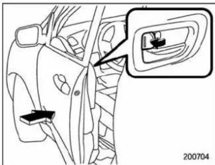
Lockingwithoutthekey
Tolockthedoorfromtheoutsidewithout thekey,rotatethelockleverrearwardand thenclosethedoor.
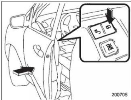
Lockingwithoutthekey
Tolockthedoorfromtheoutsideusingthe
powerdoorlockingswitch, pushthe" sidesoftheswitchandthenclosethe door. In this case, all closed doors and the reargate are locked at the same time.
Alwaysmakesurethatalldoorsandthe reargatearelockedbeforeleavingyour vehicle.
NOTE
Makesurethatyoudonotleavethekey insidethevehiclebeforelockingthe doorsfromtheoutsidewithoutthekey.
■Lockingandunlockingfrom theinside

WARNING
Keepalldoorslockedwhenyou drive,especiallywhensmallchildrenareinyourvehicle.
Alongwiththeproperuseofseat-beltsandchildrestraints,locking thedoorsreducesthechanceof beingthrownoutofthevehicleinan accident.
-CONTINUED-
2-6Keysanddoors
It also helps prevent passengers from falling out if a door is accidentally opened, and intruders from unexpectedly opening doors and entering your vehicle.
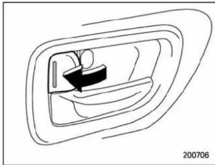
natural_image
Line drawing of a car door with a seatbelt and handle, no text or symbols presentTolockthedoorfromtheinside,rotatethe lockleverrearward.
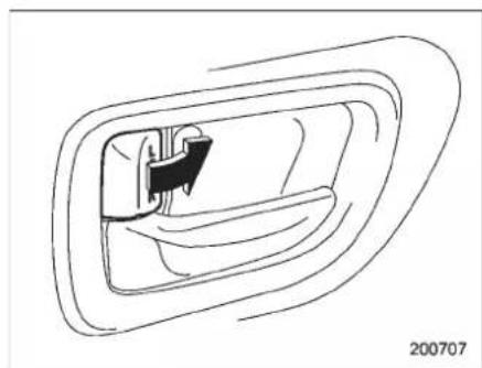
natural_image
Line drawing of a car door with a handle and seat, no text or symbols presentTounlockthedoorfromtheinside,rotate thelockleverforward.
Theredmarkonthelockleverappears whenthedoorisunlocked.
Pulltheinsidedoorhandletoopenan unlockeddoor.
Alwaysmakesurethatalldoorsandthe reargateareclosedandlockedbefore startingtodrive.
■Batterydrainageprevention function
Ifanyofthedoorsorthereargateisnot completelyclosed, theinteriorlightswill remainilluminatedasaresult. However, severallightsareautomaticallyturnedoff bythebatterydrainagepreventionfunctiontopreventthebatteryfromdischar-
ging. The following interior lights are affected by this function.
| Item | Switch position | Automatically turning off |
| MaplightsOFF | Approximately 30 secondslater | |
| Domelight | DOOR | Approximately 10 minuteslater |
| Ignition switchlight | — | Approximately 10 minuteslater |
| Doorstep lights | — | None* |
| Cargoarea light | DOOR | None* |
*:Doorsteplightsandthecargoarealightare notaffectedbythebatterydrainageprevention function,sothelightsdonotturnoffautomatically.Totumoffthelights,itisnecessarythat eachdoorandthereargatearecompletely closed.
Theoperational/non-operationalsettingof thisfunction canbe changedby a SUBARUdealer.ContactyourSUBARU dealertochangethesetting.
NOTE
- Thefactorysetting(defaultsetting) forthisfunctionissetas "operational".
- Whenleavingthevehicle,please makesurethatalldoorsandtherear
Keysanddoors2-7
gatearecompletelyclosed. ●The batterydrainageprevention functiondoesnotoperatewhilethe keyisintheignitionswitch.
Frontpassenger'sswitch
1)Lock
2) Unlock
Alldoorsandthereargatecanbelocked and unlocked by the power door locking switches located at the driver's side and the front passenger's sides doors.
Tolockalldoorsandthereargate, push the "☐" sideoftheswitch. Tounlockalldoorsandthereargate, push the "☐" sideoftheswitch.
Whenyouclosethedoorsafteryouset thedoorlocks,thedoorsremainlocked.
NOTE
Makesurethatyoudonotleavethekey insidethevehiclebeforelockingthe doorsfromtheoutsideusingthepower
-CONTINUED-
2-8Keysanddoors
This function preventsthedoors from being locked with the keystill in the ignitionswitch.
▼Behaviorwithkeylock-inpreventionfunctionoperational
- Witheitherthedriver'sorfrontpassenger'sdooropen, thedoorsautomatically remainunlockedevenifthe" 🔔 sideofthe doorlockingswitchispushed.
- It is possible to lock the all doors and thereargate by holding the " ” side of the door lockings switch pushed for 3 seconds with the driver's door open and then closing the driver's door.
▼Behaviorwithkeylock-inpreventionfunctionnon-operational
- Ifthelockleveristurnedtotherear ("LOCK")positionwiththedriver'sdoor openandthedriver'sdooristhenclosed withthelockleverinthatposition,the driver'sdoorislocked.
- If the spare key is used to lock the driver's door from the outside of the vehicle, the door is locked.
Thisfunction'soperational/non-opera-
tionalsettingcanbechangedbya SUBARUdealer.ContactaSUBARU dealerfordetails.
NOTE
Whenleavingthevehicle,makesure youareholdingthekeybeforelocking thedoors.
Remotekeylessentrysystem

CAUTION
- Donotexposetheremotetransmittertosevereshocks, such as thoseexperiencedasaresultof droppingorthrowing.
- Donottaketheremotetransmitterapartexceptwhenreplacing thebattery.
- Donotgettheremotetransmitter wet.lfitgetswet,wipeitdrywith aclothimmediately.
- Whenyoucarrytheremotetransmitter on an airplane, do not pressthebuttonoftheremote transmitterwhileintheairplane. Whenanybuttonoftheremote transmitterispressed, radio wavesaresentandmayaffect theoperationoftheairplane. Whenyoucarrytheremotetransmitterinabagonanairplane, takemeasurestoppreventthe buttonsoftheremotetransmitter frombeingpressed.
This device complies with Part 15 of the FCC Rules and with RSS-210 of Industry Canada. Operation is subject
tothefollowingtwoconditions:(1)This devicemaynotcauseharmfulinterference,and(2)thisdevicemust acceptanyinterferencereceived,includinginterferencethatmaycause undesiredoperation.
Changes or modifications not expressly approved by the party responsible for compliance could void the user's authority to operate the equipment.
Thetransmitterfortheremotekeyless entrysystemislocatedinsidethekey head.
Theremotekeylessentrysystemhas the following functions.
- Lockingandunlockingthedoorsand reargatewithoutakey
●Unlockingthereargatewithoutkey
●Soundingapanicalarm - Arminganddisarmingthealarmsystem.Fordetailedinformation,referto "Alarmsystem"2-16.
Theoperabledistanceoftheremote keylessentrysystemisapproximately30 feet(10meters).However,thisdistance willvarydependingonenvironmental conditions.
Thesystem'soperabledistancewillbe shorterinareasnearafacilityorelectronic equipmentemittingstrongradiowaves suchasapowerplant,broadcaststation, TVtower,orremotecontrollerofhome electronicappliances.
NOTE
Theremotekeylessentrysystemdoes notoperatewhentheignitionkeyis insertedintheignitionswitchorwhen anyofthedoorsorthereargateisnot fullyclosed.
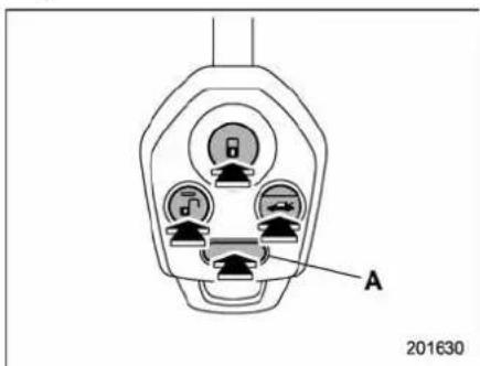

Reargateunlockbutton
Unlock/disarmbutton

_lock/armbutton
A: Panicbutton
■Lockingthedoors
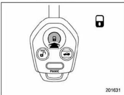
Pressthe" Button to lock all doors and reargate. An electronic chirp will sound once and the turnsignallightswillflash once.
Ifanyofthedoorsorthereargateisnot fullyclosed,anelectronicchirpwillsound fivetimesandtheturnsignallightswill flashfivetimestoalertyouthatanyofthe doorsorthereargateisnotproperly closed.Whenyouclosethedoor,itwill automatically lock and then an electronic chirp will sound once and the turn signal lightswillflashonce.
-CONTINUED-
2-10Keysanddoors
■ Unlockingthedoors
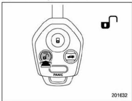
Pressthe""buttontounlockthedriver's door.Anelectronicchirpwillsoundtwice andtheturnsignallightswillflashtwice. Tounlockalldoorsandthereargate, brieflypressthe" buttonasecondtime within5seconds.
NOTE
If the interval between the first stand second presses of the "button (for unlocking of all of the doors and the reargate) is extremely short, the system may not respond.
■ Unlockingthereargate
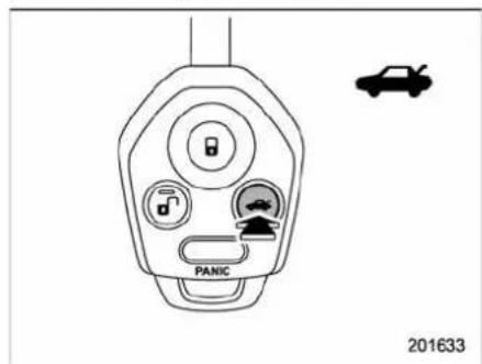
Pressingthe ""b" onopenstherear gate.
Anelectronicchirpwillsoundtwice and theturnsignallightswillflashtwice.
■Illuminatedentry
Interiorlightssuchasthemaplight, dome light and cargo area light will illuminate whenthe" "buttonispressed. These lightsremainilluminatedforapproximately 30secondsifanyofthedoorsortherear gateisnotopened.
Ifthe "buttonispressedbefore30 seconds have elapsed, theselights will turnoff. Toactivate this function, set the following interior light switches to the indicated
positions:
Maplight:OFFposition
Use this function to find your vehicle parked among many vehicles in large parking lot. Provided you are within 30 feet (10 meters) of the vehicle, pressing the "button three times a second period will cause your vehicle's horn to sound once and turn signal light to flash three times.
NOTE
If the interval between pressesistoo short when you press the "button threetimes, the system may not respond to the signals from theremote transmitter.
Soundingapanicalarm
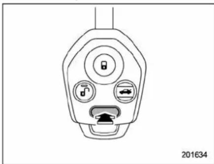
natural_image
Line drawing of a car power plug with three buttons and a connector (no text or symbols)Toactivatethealarm, pressthe "PANIC" buttononce.
Thehornwillsoundandtheturnsignal lightswillflash.
Todeactivatethepanicalarm,pressany buttonontheremotetransmitter.Unlessa buttonontheremotetransmitteris pressed,thealarmwillbedeactivated afterapproximately30seconds.
■ Selectingaudiblesignaloperation
Usinganelectronicchirp, thesystemwill giveyouanaudiblesignalwhentedoors lockandunlock.lfdesired,youmayturn theaudiblesignaloff.
Dothefollowingtodeactivatetheaudible
signal.Youcanalsousethesamesteps torestorethefunction.
- Sitinthedriver'sseatandshutall doorsandthereargate.
- HolddowntheUNLOCKsideofthe powerdoorlockingswitch.
- While holding down the "UNLOCK" side of the power door lockings switch, pull the key out and re-insert it into the ignition switch at least 6 times within 10 seconds after Step 2.
- Openandclosethedriver'sdooronce within 10 seconds after step 3.
- Theturnsignallightsflash3timesto indicatecompletionofthesetting.
Youmayhavetheabovesettingsdoneby yourSUBARUdealer.
■Replacingthebattery

CAUTION
- Donotletdust, oil orwatergeton orinthetransmitterwhenreplacingthebattery.
- Becarefulnottodamagethe printedcircuitboardinthetransmitter whenreplacingthebattery.
- Be carefulnottoallow childrento touchthebatteryandanyremovedparts;childrencould
swallowthem.
- Thereisadangerofexplosionif anincorrectreplacementbattery isused. Replaceonly withthe sameorequivalenttypeofbattery.
- Batteriesshouldnotbeexposed toexcessiveheatsuchassunshine,fireorthelike.
Whenthetransmitterbatterybeginstoget weak,transmitterrangewillbeginto decrease.Replacethebatteryassoon aspossible.
Toreplacethebattery:
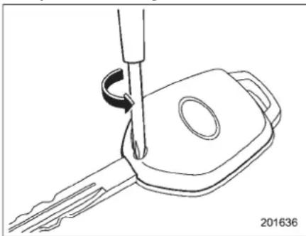
natural_image
Line drawing of a key being inserted into a car key (no text or symbols)- Removethescrewonthekeyhead.
2-12Keysanddoors
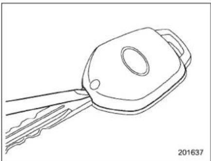
natural_image
Line drawing of a key with a handle and blade, no text or symbols present- Openthekeyheadusingaflat-head screwdriver.
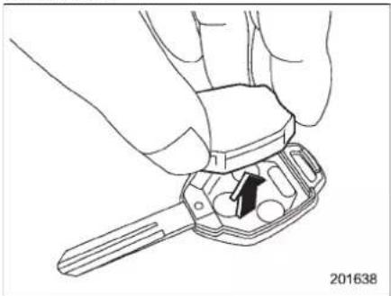
natural_image
Line drawing of a hand holding a key inserted into a small component, with no visible text or symbols- Removethetransmittercasefromthe keyhead.
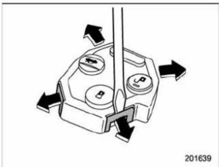
natural_image
Mechanical diagram showing a rotating component with arrows indicating motion, no text or symbols present-
Openthetransmittercasebyreleasing thehooks.
-
Remove the old battery from the holder.
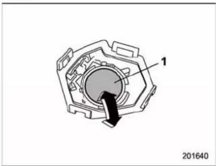
natural_image
Technical diagram of a mechanical component with labeled parts (1 and 201640), no readable text or symbols beyond labels1) Negative(-) sidefacingup
-
Replace with anewbattery (Type CR1620 equivalent) makingsureto install thenewbattery with thenegative (-) sidefacing up.
-
Puttogetherthetransmittercaseby fittingthehooksonbothsidesofthecase.
- Putthetransmittercaseinthekey headandthenputtogetherthekeyhead.
- Reinstallthescrewonthekeyhead.
Afterthebatteryisreplaced, the transmitter must besynchronized with the remote key less entry system's control unit. Presseither the "or" button six timestosynchronizethe unit.
■ Replacinglosttransmitters
If you lose at transmitter or want to purchase additional transmitters (upto four can be programmed), you should re-program allof your transmitters for security reasons. It is recommended that you have your dealer program allof your transmitters into your system.
▼Programmingthetransmitters
Theremotekeylessentrysystemis equippedwithaspecialcodelearning featurethatallowsyoutoprogramnew transmittercodesintothesystemorto deleteoldones. Thesystemcanlearnup tofouruniquetransmittercodes. Thefour transmittercodes maybethe sameor
different.
Programmingtransmittercodesinto system:
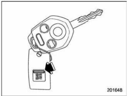
natural_image
Line drawing of a key with a digital display and keychain, no text or symbols presentKeytag
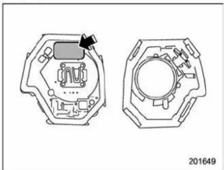
natural_image
Technical line drawing of a mechanical component with two views (top and side), no visible text or symbolsTransmittercircuitboard
Toregisteranewtransmitterwiththe
remotekeylessentrysystem,itisnecessarytoprogramthetransmitter'scode (identificationnumber)intothesystem.A tagshowingthecodeisaffixedtothekey unit,andanotherisaffixedtothecircuit boardinsidethetransmitter.Ifthereisno tag,openthetransmittercaseandmakea noteoftheeight-digitnumber.Program thenumberintothesysteminaccordance withthefollowingprocedure.
- Firmlyclosethedsandtherear gate.
- Openthedriver'sdoor, sitonthe driver'sseat, andclosethedoor.
- Perform the following steps within 45 seconds.
natural_image
Line drawing of a car interior showing seatbelt and door, with no text or symbols present(1) Open and close the driver's door once.
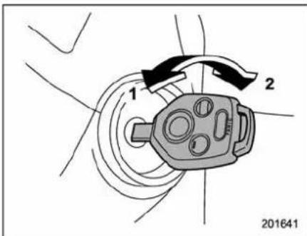
1) LOCK
2) ON
(2) Insertthekeyintotheignition switch, then turn it from the "LOCK" positiontothe"ON"position10times within15seconds.
NOTE
- Whenyoucompletestep(2),an electronictonewillsoundonce,a buzzer will continue to sound and the interiorlightwillcontinuetoflashuntil thetransmittercodesarecompletely registered.
- If you do not perform steps (1) and (2) within 45 seconds, an error will occur. Neither an electronic tonenor the buzzer will sound, and the interior lamp will not flash. In this event, per-
-CONTINUED-
2-14Keysanddoors
formthewholeprocedureagainbeginningwithpart1.
- Open and closetedoor once within 15 seconds.
NOTE
- Whenpart4oftheprocedureis completed, anelectronicitonewill soundfor30seconds. - Ifyoudonotperformtheoperations inpart4within15seconds, anerror willoccurandtheelectronictonewill notsound. Inthisevent, performthe registrationstepsagainbeginningwith part3oftheprocedure.
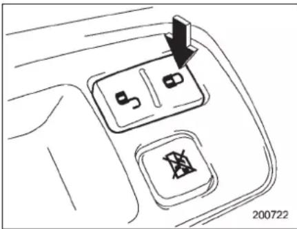
natural_image
Diagram of a car interior showing two switches with a downward arrow, no text or symbols present- Before the electronic stop sounds sounding, pushthe "side of the power doorlockings switch the samenumber of times as the left most digit of the transmit-
tercode. Forexample, pushthelocking switcheighttimesiftheleftmostdigitof thecodeis8.
NOTE
- Theelectronictonewillstopsoundingwhenyoustartenteringthenumber.
- If you donotstartentering the number using the lock knob before the electronic nestopssounding, an error will occur. In this event, perform theregistration steps again beginning with part 3 of the procedure.
- If the interval between none push of the knob and then next exceeds 5 seconds, an error will occur. In this event, perform the procedure again beginning with part 4. If an error occurs six times, perform the procedure again starting with part 3.
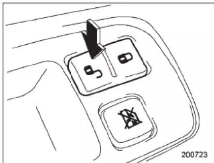
natural_image
Diagram of a car interior showing two switches with a black arrow pointing to the top switch (no text or symbols present)- When you have finished entering the number, push the "☐" side of the locking switch within 5 seconds.
NOTE
- Anelectronictonewillsound. - Ifyoupushthe" 🔍”sideofthe lockingswitchwhenmorethan5 secondshavepassed,anerrorwill occur.Inthisevent,performtheprocedure again beginning with part 4. If an erroroccurssixtimes,performthe procedureagainstartingwithpart3.
- Perform parts 5 and 6 of the procedure foreachoftheremaining digit so the transmitter code beginning with these second digit (counting from the left) and finishing with the eighth digit.
NOTE
- Whenyoufinishenteringtheeighth digit, anelectronictonewillsoundfor 30seconds.
- If the interval between none push of the switch and then next exceeds 5 seconds, an error will occur. In this event, perform the procedure again beginning with part 4. If an error occurs six times, perform the procedure again starting with part 3.
- Before the electronic stop sounding, use the power door locking switch to enter the transmitter code beginning with the left most digit.
NOTE
If you donotstartentering then number using the lock knob before the electronicist on stop sounding, an error will occur. In this event, perform the procedure again beginning with part 3.
- When you have finished entering the codeasecondtime, an electronic tonewill sound for 1 second and automatic door locking and unlocking operation will take place on ceto indicate completion of registration, provided the code entered these second time is identical to that entered the first time.
NOTE
Ifthecodeenteredthesecondtimeis not identical tothecodeenteredthe first time,anerrorwilloccur. Inthis event,performtheprocedureagain beginningwithpart5.Ifanerroroccurs fivetimes,performtheprocedureagain startingwithpart3.
- If you wish to program another transmitter code into the system (up to four transmitter codes can be programmed into the system), perform the procedure beginning with part 4. When you have finished programming allothen necessary transmitter codes into the system, remove the key from the ignition switch.
- Testeveryregisteredtransmitterto confirmcorrectoperation.
▼Deletingoldtransmittercodes
The control unit of the remote key less entry system has four memory location to store transmitter codes, giving the ability to operate with up to four transmitters.
Whenyouloseatransmitter, thelost transmitter's coderemainsinthememory. Forsecurityreasons, losttransmitter codesshouldbedeletedfromthememory.
Todeleteoldtransmittercodes, program fourtransmittercodes into the system. If
youhaveonlyonecurrenttransmitter, programitfourtimes.Ifyouhavetwo currenttransmitters,programeachone twice.Ifyouhavethreecurrenttransmitters,programtwoofthemonceandthe thirdone twice.This processwillleave onlycurrenttransmittercodesinthe system'smemory.
NOTE
Makesurenooneelseisoperating theirkeylessentrysystemwithinrange ofyourvehiclewhenprogramming transmitters.Ifsomeoneelsewereto operatetheirremotetransmitterwhile youareprogrammingyourtransmitters,itispossiblethattheirtransmitter codewillbeprogrammedintoyour system,allowingthemunauthorized accesstoyourvehicle.
2-16Keysanddoors
Alarmsystem
Thealarmsystemhelpstoprotectyour vehicleandvaluablesfromtheft. Thehorn soundsandtheturnsignallightsflashif someoneattemptstobreakintoyour vehicle.
Thesystemcanbearmedanddisarmed withtheremotetransmitter.
Thesystemdoesnotoperatewhenthe keyisinsertedintotheignitionswitch.
Yourvehicle'salarmsystemhasbeenset foractivationatthetimeofshipmentfrom thefactory.Youcansetthesystemfor deactivationyourselforhaveitdoneby yourSUBARUdealer.
Systemoperation
Thealarmsystemwillgivethefollowing alarmswhentriggered.
- Thevehicle'shornwillsoundfor30 seconds.
- Theturnsignallightswillflashfor30 seconds.
Ifanyofthedoorsorthereargateremains openafterthe30-secondperiod,thehorn willcontinuetosoundforamaximumof3 minutes.Ifanyofthedoorsortherear gateisclosedwhilethehornissounding, thehornwillstopsoundingwithadelayof
upto30seconds.
Thealarmistriggeredby:
- Opening any of the doors or there are gate
- Physicalimpacttothevehicle, such as forcedentry(onlyvehicleswithshock sensors(dealeroption))
NOTE
Thealarmsystemcanbesettotrigger theilluminationofthefollowinginterior lights.
- Domelight(illuminatesonlywhen thedomelightswitchisinthe"DOOR" position)
-Maplights
Thenotificationsregardingthedome lightandthemaplightsaredeactivated asthefactory setting.ASUBARU dealercanactivatethesystem.Contact yourSUBARUdealerfordetails.
■ Activating and deactivating the alarmsystem
Tochangethesettingofyourvehicle's alarmsystemforactivationordeactivation,dothefollowing.
- Disarm the alarm system. Refer to "Disarmingthesystem" 2-18.
- Sitinthedriver'sseatandshutall
doorsandthereargate.
- Turntheignitionswitchtothe"ON" position.
- HolddowntheUNLOCKsideofthe driver'spowerdoorlockingswitch,open the driver's door within the following 1 second, and wait 10 seconds without releasingtheswitch.Thesettingwillthen bechangedasfollows.
If the system was previously activated:
Theodometer/tripmeterscreendisplays "AL of" and the horn sounds twice, indicating that the system is now deactivated.
If the system was previously deactivated:
Theodometer/tripmeterscreendisplays "AL on" and the horn sounds once, indicating that the system is now activated.
NOTE
You may havethe abovesetting changedonebyyourSUBARUdealer.
■ If you have accidentally triggered the alarmsystem
▼Tostopthealarm
Doanyofthefollowingoperations.
- Pressanybuttonontheremotetransmitter.
- Turntheignitionswitchtothe"ON" position.
Armingthesystem
▼Toarmthesystemusingremote transmitter
- Closeallwindowsandthemoonroof.
- Removethekeyfromtheignition switch.
- Openthedoorsandgetoutofthe vehicle.
- Makesurethattheenginehood is locked.
- Closealldoorsandthereargate.
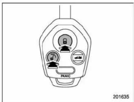
:PresstoArmthesystem. :PresstoDisarmthesystem.
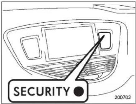
6.Brieflypressthe""button(forless than2seconds).Alldoorsandtherear gate will lock, an electronic chirp will sound once, the turn signal lights will flash
onceandtheindicatorlightswillstart flashingrapidly.Afterrapidflashingfor30 seconds(standbytime),theindicator lightswillthenflashslowly(twiceapproximatelyevery2seconds),indicatingthat thesystemhasbeenarmedforsurveillance.
Ifanyofthedoorsorthereargateisnot fullyclosed,anelectronicchirpsounds fivetimes,theturnsignallightsflashfive times to alert you that the doors or the rear gatearenotproperlyclosed.Whenyou close the door, the system will automatically arm and doors will automatically lock.
▼Toarmthesystemusingpower doorlockingswitches
1.Closeallwindows.
2. Removethekeyfromtheignition switch.
3. Openthdoors and get out of the vehicle.
4. Makesurethattheenginehood is locked.
5. Closethedoorsandthereargatebut leaveonlythedriver'sdoororthefront passenger'sdooropen.
-CONTINUED -
2-18Keysanddoors
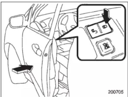
- Pushthefrontside("LOCK" side) of the powerdoorlockingswitchtosetthe doorlocks.
- Closethedoor. Anelectronicchirpwill soundonce, theturnsignallightswillflash once and the indicator lightswillstart flashing rapidly. After rapid flashing for 30 seconds (standby time), the indicator lightswill then flash slowly (twice approximately every 2 seconds), indicating that the system has been armed for surveillance.
NOTE
- Thesystemcanbearmedevenifthe enginehood, the windows and/or moonroofareopened. Alwaysmake surethattheyarefullyclosedbefore armingthesystem.
- The30-secondstandbytimecanbe eliminatedifyou prefer.Haveit performedbyyourSUBARUdealer.
- Thesystemisinthestandbymode fora30-secondperiodafterlockingthe doorswiththeremotetransmitter.The securityindicatorlightwillflashat shortintervalsduringthisperiod.
-
If any of the following actions is done during the standby period, the system will not switch to the surveillance state.
-
Doors are unlocked using the remotetransmitter.
-Anyofthedoorsorthereargate isopened. - Ignition switch is turned to the "ON" position.
■Disarmingthe system
Brieflypressthe" Button(forlessthan 2seconds)ontheremotetransmitter.The driver'sdoorwillunlock,anelectronic chirpwillsoundtwice,theturnsignal lights will flash twice and the indicator lightwillturnoff.
Tounlockallotherdoors and therear gate, briefly press the "buttona second timewithin5 seconds.
NOTE
If theintervalbetween thefirst and secondpressesofthe" "button(for unlockingofallofthedoorsandthe rear gate) is extremely short, the systemmaynotrespond.
▼Emergencydisarming
If you cannot disarm the system using the transmitter (i.e. the transmitter is lost, broken the transmitter battery is too weak), you can disarm the system without using the transmitter.
The system can be disarmed if you turn theignitionswitchfromthe"LOCK"tothe "ON"positionwitharegisteredkey.
■ Valetmode
Whenyouchoosethevalet mode, the alarmsystemdoesnotoperate.Invalet mode,theremotetransmitterisusedonly forlockingandunlockingthedoorsand reargateandpanicactivation.
To enter the valet mode, change the setting of your vehicle's alarmsystem for deactivation mode. Referto "Activating and deactivating the alarmsystem" 2-16. Theseurity indicator lightwill continuetoflashonce every 3 seconds indicating that the system is in the valet mode.
Toexitvaletmode, changethesetting of your vehicle'salarmsystem for activation mode. Referto "Activating and deactivating the alarmsystem" 2-16.

Passivearming
Whenpassivearmingmodehasbeen programmedbythedealer,armingofthe systemisautomaticallyaccomplished withoutusingtheremotetransmitter.Note thatinthismode,DOORSMUSTBE MANUALLYLOCKED.

Toenterthepassivemode
If you wishtoprogram the passive arming mode, have it done by your SUBARU dealer.

Armingthesystem

CAUTION
Inpassivemode, thesystemwill automaticallyactivatethealarmbut WILLNOTautomaticallylockthe doors. Inordertolockthedoors youmusteitherlockthemasindicatedinstep4beloworwiththe keyonctheyhavebeenclosed. Failuretolockthedoorsmanually willresultinahighersecurityrisk.
- Turntheignitionswitchtothe"ON"
position.
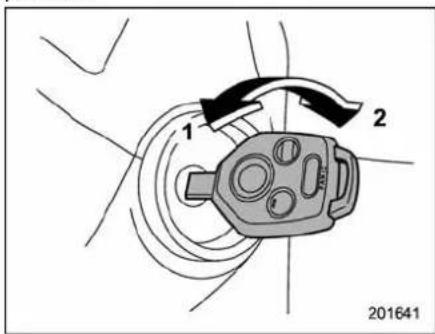
1)LOCK 2)ON
- Turntheignitionswitchfrom"ON"to "LOCK"positionandremovethekeyfrom theignitionswitch.
- Openthedoorsandgetoutofthe vehicle.
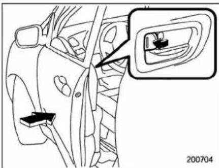
- Before closing the doors, lock all doors withtheinsidedoorlocklevers.
- Closethedoors. Thesystemwill automaticallyarmafter1 minute.
Inthepassivemode, thesystemcanalso bearmed with theremotetransmitteror with the power door lockings switches. If theremotetransmitter or power door lockings switch is used to lock the vehicle, arming will take place immediately regardless of whether or not the passiv mode has been selected.

Disarmingthesystem
Todisarmthesystem, briefly press the "buttononthetransmitter.
-CONTINUED-
2-20Keysanddoors
■ Trippedsensoridentification
Theseurityindicatorlightflasheswhen thealarmsystemhasbeentriggered. Also,thenumberofflashesindicatesthe locationofunauthorizedintrusionorthe severityofimpactonthevehicle.
When the ignition switch is turned to the "ON" position, the indicator light will illuminate for 1 second and then flash as follows.
- Whenadoororreargate was opened: 5times
- Whentheignitionswitchwasturned to the "ON" positionbyusingakeynot registeredwithyourimmobilizersystem:3 times
- When a strong impact form multiple impacts were sensed: twice (only vehicles with shocks sensors (dealer option))
- Whenalightimpactwassensed:once (onlyvehicleswithshocksensors(dealer option))
NOTE
Anyoftheaboveindicatorlightflashing patterns will recur each time the ignitionswitchisturned tothe"ON" position. Rearmingthealarm system cancelstheflashingpatternofthe securityindicatorlight.
■Shocksensors(dealeroption)
Theshocksensorstriggerthealarm systemwhentheysenseimpactsapplied tothevehicleandwhenanyoftheir electric wiresiscut.The alarmsystem causes the horn to sound and the turn signallightstoflashforashorttimewhen thesensedimpactisweak,butitwarnsof astrongimpact ormultipleimpacts by soundingthehornandflashingtheturn signallights,both lastingapproximately 30 seconds.
If youdesire, your SUBARU dealer can connect them and set them for activation or deactivation.
NOTE
- Theshocksensorsarenotalways able tosenseimpactscaused bybreakingin,andcannotsenseanimpactthat doesnotcausevibration(suchas breakingtheglassusingarescue hammer).
- The shock sensors may sense vibrationlikethoseshowninthefollowinglistandtriggerthealarmsystem. Selectthesettingsofthealarmsystem andshocksensors appropriately dependingonwhereyouusuallypark yourvehicle.
Example:
-Vibrationfromconstructionsite
-Vibrationinmultistorycarpark
-Vibrationfromtrains
- Youcanhavethesensitivityofthe shock sensorsadjusted toyourpreferencebyyourSUBARUdealer.
Childsafetylocks

WARNING
Alwaysusethechildsafetylock wheneverachildridesintherear. Seriousinjurycouldresultifachild accidentallyopenedthedoorand fellout.
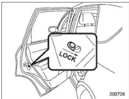
Eachreardoorhasachildsafetylockthat preventsthedoorsfrombeingopened eveniftheinsidedoorhandleispulled.
Whenthechildsafetylockleverisinthe lockposition, thedoorcannotbeopened frominsideregardlessofthepositionof theinnerdoorhandlelocklever. Thedoor canonlybeopenedfromtheoutside.
Windows

Powerwindows

WARNING
To avoid serious personal injury caused by entrapment, always conform to the following instructions without exception.
- Whenoperatingthepowerwindows,beextremelycarefulto preventanyone'sfingers,arms, neckorheadfrombeingcaught inthewindow.
●Alwayslockthepassengers'windowsusingthelockswitchwhenchildrenareridinginthevehicle.
●Beforeleavingthevehicle,alwaysremovethekeyfromtheignitionswitchforsafetyandneverallowanunattendedchildtoremaininthevehicle.Failuretofollowthisprocedurecouldresultinjurytoachildoperatingthepowerwindow.
The power windows operate only when the ignition switch is in the "ON" position.
▼Driver'ssideswitches
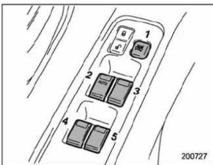
1)Lockswitch
2) Fordriver'swindow
3) Forfrontpassenger'swindow
4) For rear left window
5) Forrearrightwindow
Alldoorwindowscanbecontrolledbythe powerwindowswitchclusteratthedriver sidedoor.
2-22Keysanddoors
Operatingthedriver'swindow
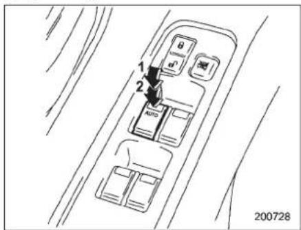
1) Open
2)Automaticallyopen
Toopen:
Pushtheswitchdownlightlyandholdit. Thewindowwillopenaslongasthe switchisheld.
Thisswitchalsohasaone-touchauto downfeaturethatallowsthewindowtobe openedfullywithoutholdingtheswitch. Pushtheswitchdownuntilclicksand releaseit,andthewindowwillfullyopen. Tostopthewindowhalfway,pullthe switchuplightly.
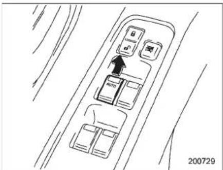
Toclose:
Pulltheswitchuplightlyandholdit. The windowwillcloseaslongastheswitchis held.
▽Operatingthepassengers'windows
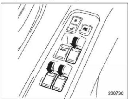
Toopen:
Pushtheappropriateswitchdownand hold it until the window reaches the desiredposition.
Toclose:
Pull the switch up and hold it until the windowreachesthedesiredposition.
Lockingthepassengers'windows
Pushthelockswitch.Whenthelock switch is in the "LOCK" position, the passengers' windowscannotbeopened orclosed.
Presstheswitchagaintocancelthe passengers'windowlocking.
NOTE
Whenthelockswitchispushedtothe "LOCK" position,theindicatorlightsin thepassenger'swindowswitches(includedinthepowerwindowswitch clusteronthedriver'sdoor)allturnoff.
▼Passengers'sideswitches
Frontpassenger'swindowswitch
1)Open
2) Close
Rearpassengers' windowswitches
1) Open
2) Close
Toopen:
Pushtheswitchdownandholdituntilthe windowreachesthedesiredposition.
Toclose:
Pulltheswitchupandholdituntilthe windowreachesthedesiredposition.
Whenthelockswitchonthepower windowswitchcluster, located on the driver's side door, is in the "LOCK" position, the passengers' windows cannot be operated with the passengers' switches.
2-24Keysanddoors
Reargate
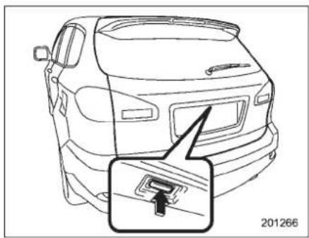
natural_image
Line drawing of a car rear bumper with a highlighted internal component (no text or symbols)Thereargatecanbelockedandunlocked usinganyofthefollowingsystems.
●Powerdoorlockingswitch: Referto "Powerdoorlockingswitches" 2-7.
- Remotekeylessentry system (if equipped): Referto "Remotekeylessentry system" 2-8.
Toopen:
Firstunlockthereargatelockthenpush thebutton.
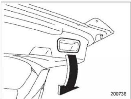
natural_image
Line drawing of a car's side profile showing a curved bracket and a black arrow indicating direction (no text or symbols)Toclose:
Lowerthereargateslowlyandpushdown firmlyuntilthelatchengages.
Thereargatecanbeloweredeasilyifyou pullitdownholdingtherecessedgrip.

WARNING
- Topreventdangerousexhaust gasfromenteringthevehicle, alwayskeepthereargateclosed whiledriving.
- Donotattempttoshuttherear gatewhileholdingtherecessed grip. Also avoid closing therear gatebypullingontherecessed gripfrominsidethecargospace. Thereisadangerofyourhand beingcaughtandinjured.

CAUTION
- Do not jam a plastic bag in or placecellophanetapeontherear gatestays orscratchthe stays whileloadingorunloadingcargo. Thatcouldcauseleakageofgas fromthestays,whichmayresult intheirinabilitytoholdtherear gateopen.
- Becarefulnottohityourheader faceonthereargatewhenopeningorclosingthereargateand whenloading or unloadingcargo.
NOTE
Ifthereargatecannotbeunlockeddue toadischargedvehiclebattery,a malfunctioninthedoorlocking/unlockingsystemorothercauses,youcan unlockitbymanuallyoperatingthe reargatelockreleaselever.Forthe procedure,referto"Reargate-ifthe reargatecannotbeunlocked" ^9 -9-18.
Moonroof(ifequipped)

WARNING
Neverletanyone'shands,arms, headoranyobjectsprotrudefrom themoonroof.Apersoncouldbe seriouslyinjuredifthevehiclestops suddenlyorturnssharplyorifthe vehicleisinvolvedinanaccident. Toavoidseriouspersonalinjury causedbyentrapment,alwaysconformtothefollowinginstructions withoutexception.
- Before closing the moonroof, makes sure that no one's hands, arms, head or other objects will be accidentally caught in the moonroof.
●Beforeleavingthevehicle,alwaysremovethekeyfromtheignitionswitchforsafetyandneverallowanunattendedchildtoremaininthevehicle.Failuretofollowthisprocedurecouldresultininjurytoachildoperatingthemoonroof.
- Nevertrytochecktheanti-en-trapmentfunctionbydeliberately placingpartofyourbodyinthe moonroof.

CAUTION
- Donotsitontheedgeoftheopen moonroof.
- Donotoperatethemoonroofif fallingsnoworextremelycold conditionshavecauseditto freezeshut.
- The anti-entrapmentfunction does not operate when the moon-roof is being tilted down. Besure to confirm that it's a set of them on roofed before tilting them on roofed down.
Themoonroofhasbothtiltingandsliding functions.
Themoonroofoperatesonlywhenthe ignitionswitchisinthe"ON"position.
2-26Keysanddoors
Tiltfunction
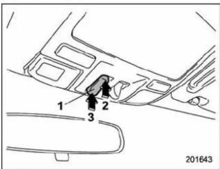
1) Tiltswitch
2) Raise
3) Lower
Thetiltingfunctionwillonlyoperatewhen themoonroofisfullyclosed.
Pushtherearsideofthe "Tilt" switchto raisethemoonroof.
Pushthefrontsideofthe"Tilt"switchto lowerthemoonroof.
Releasetheswitchafterthemoonroofhas beenraisedorhasbeenloweredcom- pletely.Pushingswitchcontinuously maycausedamagetothemoonroof.
NOTE
One-touch operation does not take place when the moonroof is raised or lowered. Push the switch continuously toraise or lower the moonroof.
■ Slidingfunction
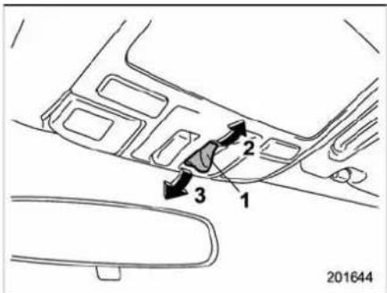
1) Open/Closeswitch
2)Open
3) Close
Pushthe "Open/Close" switch rearward to openthemoonroof. Thesunshadow will also be opened together with the moon-roof.
Pushthe"Open/Close"switchforwardto closethemoonroof.Themoonroofwill stophalway.Pushitagaintoclosethe moonroofcompletely.
Tostopthemoonroofataselectedmid-waypositionwhileopeningorclosingit, momentarilypushthe switchto the "OPEN" or "CLOSE" side.
Afterwashingthevehiclerafteritrains, wipeawaywater on theroof prior to openingthemoonrooftopreventdrops of water from falling into the passenger compartment.
■ Anti-entrapmentfunction
Whenthemoonroofsensesasubstantial enoughobjecttrappedbetweenitsglass andthevehicle'sroofduringclosure, it automaticallymovesbacktoeitherofthe followingpositionsaccordingtothepoint atwhichitsensestheobject.
- Whenthemoonroofsensestheobject atapoint between thehalfwaystop positionandfullyclosedposition,itmoves back to the halfway stop position and stopsthere.
- Whenthemoonroofsensestheobject atapoint between the halfway stop position and fully open position, it moves back to the fully open position and stops there.
Theanti-entrapmentfunctionmayalsobe activatedbyastrongshockonthemoon-roofevenwhenthereisnothingtrapped.

CAUTION
Neverattempttotestthisfunction usingfingers,handsorotherparts ofyourbody.
NOTE
Forthesakeofsafety,itisrecommendedthatyouavoiddrivingwiththe moonrooffullyopened.
Sunshade
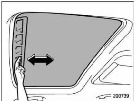
natural_image
Diagram showing a hand pressing down on a car's front panel with a double-headed arrow indicating leftward movement (no text or symbols)Thesunshade can be slid forwardor backward by hand while the moon roof is closed. If the moon roof is opened, the sun shade also moves back.
| -1.5 | -1.5 | -1.5 | -1.5 |
Instruments and controls
Ignitionswitch....3-3
LOCK....3-3
Acc....3-4
ON 3-4
START....3-4
Keyreminderchime....3-4
Ignitionswitchlight....3-4
Hazardwarningflasher....3-5
Metersandgauges....3-5
Combinationmeterillumination....3-5
Canceling the function formeter needle/gauge movement and combination meter sequential illumination upon turning on the ignition
switch....3-5
Speedometer....3-6
Odometer....3-6
Doubletripmeter....3-7
Tachometer....3-7
Fuelgauge....3-8
Temperaturegauge....3-9
Warningandindicatorlights....3-9
Seatbeltwarninglightandchime....3-10
SRSairbagsystemwarninglight.... 3-11
Frontpassenger'sfrontalairbagONandOFF indicators....3-12
CHECKENGINEwarninglight/Malfunction indicatorlamp....3-12
Chargewarninglight....3-13
Oilpressurewarninglight....3-13
ATOILTEMPwarninglight....3-13
Reardifferentialoiltemperaturewarning light 3-14
Lowtirepressurewarninglight.... 3-14
ABSwarninglight.... 3-15
Brakesystemwarninglight.... 3-16
Lowfuelwarninglight.... 3-17
Dooropenwarninglight.... 3-17
Windshieldwasherfluidwarninglight.... 3-18
All-WheelDrivewarninglight.... 3-18
VehicleDynamicsControloperationindicator light 3-18
VehicleDynamicsControlwarninglight/Traction ControlsystemOFFindicatorlight.... 3-18
Securityindicatorlight.... 3-19
SPORTmodeindicatorlight.... 3-20
Selectlever/Gearpositionindicator.... 3-20
Turnsignalindicatorlights.... 3-20
Highbeamindicatorlight.... 3-20
Cruisecontrolindicatorlight.... 3-20
Cruisecontrolsetindicatorlight.... 3-21
Headlightindicatorlight.... 3-21
Frontfoglightindicatorlight 3-21
Clock....3-21
Outsidetemperatureindicator.... 3-22
Lowoutsidetemperaturewarning.... 3-22
Multifunctiondisplay(vehicleswithouta
genuineSUBARUnavigationsystem)......3-23
Currentfuelconsumption.... 3-23
Averagefuelconsumption.... 3-24
Drivingrangeonremainingfuel.... 3-24
Journey time 3-25
Instrumentsandcontrols
Lightcontrolswitch....3-26
Headlights....3-26
High/lowbeamchange(dimmer)....3-27
Headlightflasher....3-27
Daytimerunninglightsystem....3-27
Turnsignallever....3-28
Illuminationbrightnesscontrol....3-28
Headlightbeamleveler(ifequipped)....3-29
For5-seatermodels....3-30
For7-seatermodels....3-31
Parkinglightswitch....3-32
Frontfoglightswitch....3-32
Wiperandwasher....3-33
Windshieldwiperandwasherswitches....3-34
Rearwindowwiperandwasherswitch....3-35
Windshieldwiperdeicer....3-36
Rearwindowdefoggerbutton....3-37
Mirrors....3-38
TypeAinsidemirror(ifequipped)....3-38
TypeBinsidemirror(ifequipped)....3-38
TypeCinsidemirror(ifequipped)....3-41
Outsidemirrors....3-42
Tiltsteeringwheel....3-44
Horn 3-44
Ignitionswitch

WARNING
- Neverturntheignitionswitchto "LOCK" while the vehicle is beingdrivenortowedbecause thatwilllockthesteeringwheel, preventingsteeringcontrol. And whentheengineisturnedoff, it takesamuchgreatereffortthan usualtosteer.
- Beforeleavingthevehicle,alwaysremovethekeyfromtheignitionswitchforsafetyandneverallowanunattendedchildtoremaininthevehicle.Failuretofollowthisprocedurecouldresultininjurytoachildorothers.Childrencouldoperatethepowerwindows,themoon-rooforothercontrolsorevenmakethevehiclemove.

CAUTION
Donotattachalargekeyholderor keycasetoeitherkey.lfitbanged againstyourkneesorhandswhile youweredriving.itcouldturnthe ignitionswitchfromthe"ON"posi-
tion to the "Acc" or "LOCK" position,therebystoppingtheengine. Also,ifthekeyisattachedtoa keyholderortoalargebunchof otherkeys,centrifugalforcemayact onitasthevehiclemoves,resulting inunwantedturningoftheignition switch.
Theignitionswitchhasfourpositions: LOCK, Acc, ONandSTART.
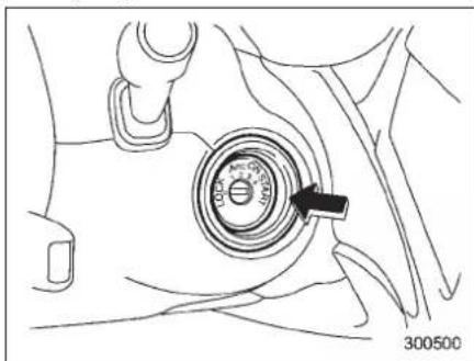
natural_image
Line drawing of a car interior with a circular dial indicator and an arrow pointing to the center (no text or symbols)NOTE
- Keeptheignitionswitchinthe "LOCK"positionwhentheengineis notrunning. - Usingelectricalaccessoriesfora longtimewiththeignitionswitchinthe "ON" or "Acc" position can cause the batterytogodead.
- If the ignitionswitch will not move from the "LOCK" position to the "Acc" position, turn the steering wheel slightly to the left and right. The ignition switch.
■LOCK
Thekeycanonlybeinsertedorremoved inthisposition.Theignitionswitchwilllock thesteeringwheelwhenyouremovethe key. Ifturningthekeyisdifficult,turnthe steeringwheelslightlytotherighttandleft asyouturnthekey.

natural_image
Diagram of a mechanical component with directional arrows indicating motion (no text or symbols)Thekeycanbeturnedfrom"Acc"to "LOCK" only when the select lever is in the "P" position.
-CONTINUED-
3-4 Instrumentsandcontrols
Acc
In this position the electrical accessories (radio, accessory power outlet, etc.) can be used.
ON
Thisisthenormaloperatingpositionafter theengineisstarted.
START

CAUTION
Donotturntheignitionswitchtothe "START"positionwhiletheengine isrunning.
Theengineisstartedinthisposition.The startercrankstheenginetostartit.When thekeyisreleased(aftertheenginehas started),thekeyautomaticallyreturnsto the"ON"position.
Ifyourregisteredkeyfailstostartthe engine,pulloutthekeyonce(thesecurity indicatorlightwillblink),andtheninsert thekeyintheignitionswitchandturnitto the"START"positionandagaintrytostart theengine.
NOTE
Theenginemaynotstartinthefollowingcases.
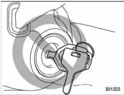
natural_image
Illustration of a key inserted into a circular lock mechanism (no text or symbols)•Thekeygripistouchinganotherkey orametallickeyholder.
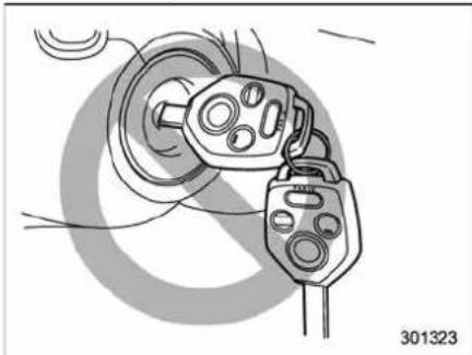
natural_image
Illustration of a plug plug inserted into a socket, with no visible text or symbols•Thekeyisnearanotherkeythat
containsanimmobilizertransponder. ●Thekeyisnearortouchinganother transmitter.
■ Keyreminderchime
Thereminderchimesoundswhenthe driver'sdooropensandthekeyisinthe "LOCK" or "Acc" positions. The chime stopswhenthekeyisremovedfromthe ignitionswitch.
Ignitionswitchlight
Foreasyaccesstotheignitionswitchin the dark, the ignition switch light illuminateswhenthedriver'sdoorisopened. Thelightremainsonforseveralseconds andthengraduallyturnsoffafterdriver's dooris closed.Also,thelight turnsoff immediately if the key is turned to the "ON" position.
Hazardwarningflasher
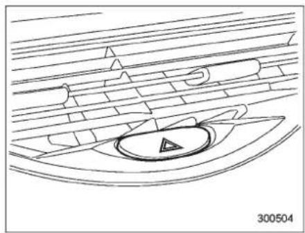
natural_image
Technical line drawing of a boat with a circular center and triangular pattern, no text or symbols presentThehazardwarningflasherisusedto warnotherdriverswhenyouhavetopark yourvehicleunderemergencyconditions. Thehazardwarningflasherworkswiththe ignitionswitchinanyposition.
Toturnonthehazardwarningflasher, pushthehazardwarningbuttononthe instrumentpanel. Toturnofftheflasher, pushthebuttonagain.
NOTE
Whenthehazardwarningflasherison, theturnsignalsdonotwork.
Metersandgauges
NOTE
Liquid-crystaldisplaysareusedin someofthemetersandgaugeson thecombinationmeter.Youwillfind theirindicationshardtoseeifyouwear polarizedglasses.
■ Combinationmeterillumination
Whentheignitionswitchisturnedtothe "ON"position,thevariouspartsofthe combinationmeterareilluminatedinthe followingsequence.
- Warninglights, indicatorlights, meter rims, meterneedles, odometer, tripmeter, and gaugebacklightsilluminate.
- Meterneedlesandgaugeseachshow MAXreading.
- Meterneedlesandgaugeseachshow MINreading.
4.Meterandgaugedialsilluminate. - Regularillumination(fordriving)begins.
NOTE
Theabovesequenceofoperationsmay nottakeplaceifyouquicklyturnthe
ignitionswitchtostarttheengine.This isnotamalfunction.
■ Canceling the function for meter needle/gaugemovement and combination meter sequential illumination upon turning on the ignitions switch
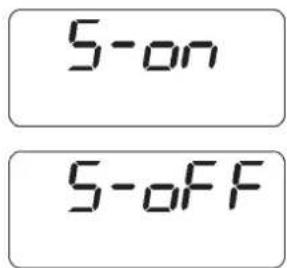
300185
Itispossibletoactivateordeactivatethe movementofthemeterneedlesand gaugesandsequentialilluminationofthe combinationmeterthattakesplacewhen theignitionswitchisturnedtothe"ON" position.
Turn the ignition switch to the "Acc" position. With the Atripmeter indication selected, briefly press the trip knob twice. You can now establish the activated/deactivated setting for movement of the
-CONTINUED-
meterneedlesandgaugeswhenthe ignitionswitchisturnedtothe"ON" position.Tochangethecurrentsetting, pressthetripknobforatleast2seconds.
5-00 : Activated
S-OFF :Deactivated
With the function deactivated, the combination meter illuminates as follows.
- Warninglights, indicatorlights, meter rims, meterneedles, odometer, tripmeter, and gaugebacklights illuminate.
- Meterandgaugedialsilluminate.
- Regularillumination(fordriving)begins.
300543
Brieflypressthetripknobagain. You can now establish the activated/deactivated setting for sequential illumination of the
combinationmeterwhentheignition switchisturnedtothe"ON"position.To changethecurrentsetting,pressthetrip knobforatleast2seconds.
- on : Activated
:Deactivated
Briefly press the knob to return to the A trip meterindication.
Ifyouturntheignitionswitchtothe
"LOCK" position, turn the ignition switch to the "ON" position, or open and close the driver's doorduring these setting procedure, thenewsetting will be canceled.
Also, if you do not press the trip knob for a period of 10 seconds, thenewsetting will be canceled.
NOTE
- Itisnotpossibletocancelsequentialilluminationofthecombination meter whilesequentialilluminationis actually takingplace. Cancelsequentialilluminationwhenregularillumination(fordriving)hasbegun.
- Whenyouopenthedriver'sdoor withtheignitionswitchinthe"LOCK" position,themeters'needlesandrims arelit.Theilluminationstopsworking whenyoushutthedriver'sdooror automaticallyafter30seconds.
Speedometer
Thespeedometershowsthevehicle speed.
Odometer
This meterdisplaysthe odometerwhen the ignition switch is in the "LOCK", "Acc" or "ON" position.
Theodometershowsthetotaldistance thatthevehiclehasbeendriven.
If you press the trip knob when the ignition switch is in the "LOCK" or "Acc" position, the odometer/tripmeterwilllightup.Ifyou donotpressthetripknobwithin10 secondsof illuminationofthe odometer/trip meter, the odometer/trip meter will turn off.
Theodometer/tripmeterwillalsoturnoffif youopenandclosethedriver'sdoor within10secondsofilluminationofthe odometer/tripmeter.
Doubletripmeter
Thismeterdisplaystwotripmeterswhen the ignition switch is in the "LOCK", "Acc" or "ON" position.
Thetripmetershowsthedistancethatthe vehiclehasbeendrivensinceyoulastset ittozero.
Tochangethemodeindication, briefly pushtheknob.
Each press of the knobchangesthemode indicationalternately.
Tosetthetripmetertozero,selecttheA triporBtripmeterbypushingtheknob andkeeptheknobpushedformorethan2 seconds.
Ifyoupressthetripknobwhentheignition switch is in the "LOCK" position, the odometer/tripmeterwilllightup.Itis possibletoswitchbetweentheAtrip meterandBtripmeterindicationswhile theodometer/tripmeterislitup.Ifyoudo notpressthetripknobwithin10seconds ofilluminationoftheodometer/tripmeter, theodometer/tripmeterwillturnoff.Also, ifyouopenandclosethedriver'sdoor within10secondsofilluminationofthe odometer/tripmeter,theodometer/trip meterwillturnoff.

CAUTION
Toensuresafety, donotattempt to changethefunctionoftheindicator duringdriving, asanaccidentcould result.
NOTE
If the connection between the combination meter and battery is broken for any reasons such as vehicle maintenance or fusereplacement, the data recorded on the tripmeter will belost.
▼Vehiclecommunicationsystem malfunctionindication
The vehicle communications system carries various types of information (vehicle speed, running conditions, etc.) to control modules. In the event of a malfunction in this communication system, the tripmeter will show "EFO".
Ifthetrip meters shows "ErOO", immediately contact thenearest SUBARU dealer and havethe vehicle communications system inspected.
NOTE
If you press the trip knob while the trip meter is showing “ErOO”, the trip meter indication will appear for 10 seconds.
Tachometer
Thetachometershowstheenginespeed inthousandsofrevolutionsperminute.

CAUTION
Donotoperatetheenginewiththe
-CONTINUED-
pointerofthetachometerinthered zone. This may cause severe damage to the engine.
NOTE
Toprotecttheenginewhiletheselect lever is in the "P" or "N" position, the engineiscontrolledsothattheengine speedmaynotbecometoohighevenif theacceleratorpedalisdepressed hard.
Fuelgauge
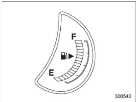
Thefuelgaugeshowstheapproximate amountoffuelremaininginthetank.
Thegaugemaymoveslightlyduring braking,turningoraccelerationduetofuel
levelmovementinthetank.
If you pressthetripknobwhiletheignition switch is in the "LOCK" or "Acc" position, the fuel gaugewillightup and indicate the amount off fuel remaining in the tank.
NOTE
natural_image
Simple black icon of a fuel pump with a play button, no text or symbols presentYouwillseethe“”sighinthefuel gaugemeter.
This indicates that the fuel filler door (lid) is located on the right side of the vehicle.
▼Lowfuelwarninglight


CAUTION
Promptlyputfuelinthetankwheneverthelowfuelwarninglight illuminates.Enginemisfiresasa resultofanemptytankcouldcause damagetotheengine.
Thelowfuelwarninglightilluminates whenthetankisnearlyempty(approximately2.6USgal[10liters,2.2Impgal]).
Itonlyoperateswhentheignitionswitchis in the "ON" position. When this light illuminates, fillthefueltankimmediately.
NOTE
Thislightdoesnotturnoffunlesssthe tankisreplenisheduptoaninternal fuel quantityof approximately4.0US gal(15liters,3.3Impgal).
Temperaturegauge
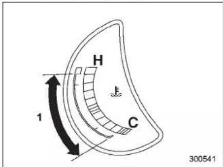
1) Normaloperatingrange
Thetemperaturegaugeshowsengine coolanttemperaturewhentheignition switchisinthe"ON"position.
Thecoolanttemperaturewillvaryin accordancewiththeoutsidetemperature anddrivingconditions.
Werecommendthatyoudrivemoderately until the pointer of the temperature gauge reaches near the middle of the range. Engine operation is optimum with the engine coolant at this temperature range. Also, high revving operation while the engine is not sufficiently warmed up should be avoided.
CAUTION
If the pointerer exceeds then normal operating range, safely stop the vehicle as soon as possible. Referto "Incase of emergency" 9-1.
Warningandindicatorlights
Severalofthewarningandindicatorlights illuminatemomentarilyandthenturnoff whentheignitionswitchisinitiallyturned tothe"ON"position.Thispermitscheckingtheoperationofthebulbs. Applytheparkingbrakeandturnthe ignitionswitchtothe"ON"position.The followinglightsilluminate.
Driver'sseatbeltwarninglight (Theseatbeltwarninglightturnsoff onlywhenthe driverfastensthe seatbelt.)
PASS 4: Frontpassenger'sseatbeltwarning light (Theseatbeltwarninglightturnsoff onlywhenthefrontseatpassenger fastenstheseatbelt.)
AIR: SRSairbagsystemwarninglight BAG
CHECK:CHECKENGINEwarninglight/Mal-functionindicatorlamp
- + :Chargewarninglight
Oilpressurewarninglight
AT OIL:ATOILTEMPwarninglight TEMP
ABS / (ABS): ABSWarninglight
-CONTINUED-
3-10 Instrumentsandcontrols
:VehicleDynamicsControloperation indicatorlight
:VehicleDynamicsControlwarning light/TractionControlsystemOFF indicatorlight
BRAKE /: Brakesystemwarninglight
AWD:AWDwarninglight
(1): Lowtirepressurewarninglight
SPORT:SPORTmodeindicatorlight
ON:Frontpassenger'sfrontalairbagON indicatorlight
Frontpassenger'sfrontalairbagOFF indicatorlight
Lowfuelwarninglight
CRUISE:Cruisecontrolindicatorlight
SET:Cruisecontrolsetindicatorlight
R.DIFF: Reardifferentialoiltemperaturewarninglight
Windshieldwasherfluidwarninglight
Dooropenwarninglight
Ifanylightsdonotilluminate, it indicates a burned-outbulboramalfunction of the correspondingsystem.
ConsultyourauthorizedSUBARUdealer
forrepair.
■ Seatbeltwarninglight andchime
Yourvehicleisequippedwithaseatbelt warningdeviceatthedriver'sandfront passenger'sseat.
Withtheignitionswitchturnedtothe"ON" position, thisdeviceremindsthedriver andfrontpassengertofastentheirseatbeltsbyilluminatingthewarninglightsin thelocationsindicatedinthefollowing illustrationsandsoundingachime.

Driver's warninglight
Frontpassenger'swarninglight
▼Operation
Ifthedriverand/orfrontpassengerhave/hasnotyetfastenedtheseatbelt(s)when theignitionswitchisturnedtothe"ON" position,theseatbeltwarninglight(s)will flashfor6seconds,towarnthatthe seatbelt(s)is/areunfastened.Ifthedriver'sseatbeltisnotfastened,achimewill alsosoundsimultaneously.
NOTE
- Ifthedriver'sand/orfrontpassenger'sseatbelt(s)is/arestillnotfastened 6secondslater,theseatbeltwarning deviceoperatesasfollowsaccording tothevehiclespeed.
- Atspeeds lower than approximately 9 mph (15 km/h)
The warninglight(s) for unfastened seatbelt(s) will alternate between steady illumination and flashing at 15-second intervals. The chimewill not sound.
- Atspeedshigherthanapproximately9mph(15km/h) Thewarninglight(s)forunfastened seatbelt(s)willalternatebetween flashingandsteadyilluminationat 15-secondintervalsandthechime willsoundwhilethewarninglight(s) is/areflashing.
-Itispossibletocancelthewarning operationthatfollowsthe6-second warningafterturningONtheignition switch.Whentheignitionswitchis turnedONnexttime,however,the completesequenceofthewarning operationresumes.Forfurtherdetails aboutcancelingthewarningoperation, pleasecontactyourSUBARUdealer.
If there is nopassengeronthefront passenger'sseat, theseatbeltwarning device for the front passenger'sseat will be deactivated. The front passenger's occupant detection system monitors whether or not there is a passenger on the front passenger's seat. Observ the following precautions. Failure todos may prevent the device from functioning correctly or causethedevicetofail.
- Donotinstallanyaccessorysuchasa tableorTVontotheseatback.
- Donotstoreaheavyloadinthe seatbackpocket.
- Donotallowtherearseatoccupantto placehis/herhandsorlegsonthefront passenger'sseatback,orallowhim/herto pulltheseatback.
If theseatbeltwarningdeviceforthefront passenger'sseatdoesnotfunctioncorrectly(e.g.,itisactivatedevenwhenthe front passenger'sseatisemptyorit is deactivatedevenwhenthefrontpassengerhasnotfastenedhis/herseatbelt), takethefollowingactions.
- Ensure that no article is placed on the seat other than a child restraint system and its child occupant.
- Ensure that there is no article left in the seatback pocket.
Ifstilltheseatbeltwarningdeviceforfront passenger'sseatdoesnotfunctioncorrectlyaftertakingrelevantcorrectiveactionsdescribedabove,immediatelycontactyourSUBARUdealerforaninspection.
■ SRSairbagsystem warninglight
AIR BAG
Whentheignitionswitchisturnedtothe "ON"position,theSRSairbagsystem warninglightwillilluminateforapproximately6secondsandturnoff. This shows theSRSfrontalairbagandSRSside airbagandSRScurtainairbagandseat-beltpretensionersareinnormaloperation.

WARNING
Ifthewarninglightexhibitsanyof thefollowingconditions,theremay beamalfunctionintheseatbelt pretensionersand/orSRSairbag system.Immediatelytakeyourvehicle toyournearestSUBARUdealer tohavethesystemchecked.Unless checkedandproperlyrepaired,the seatbeltpretensionersand/orSRS airbagswilloperateimproperly(e.g. SRS airbags may inflate in a very minorcollisionornotinflateina severecollision),whichmayincreaseetheriskofinjury.
- Flashingorflickeringofthewarninglight
- Noilluminationofthewarning lightwhentheignitionswitchis firstturnedtothe"ON"position
-CONTINUED-
3-12 Instrumentsandcontrols
•Continuousilluminationofthe warninglight
- Illuminationofthewarninglight whiledriving
■Frontpassenger'sfrontal airbagONandOFFindicators
ON :Frontpassenger'sfrontalairbagON indicator
:Frontpassenger'sfrontalairbagOFF indicator
Thefrontpassenger'sfrontalairbagON andOFFindicatorsshowyouthestatusof thefrontpassenger'sSRSfrontalairbag. Theindicatorsarelocatedinthecenter portionofthedashboard.
Whentheignitionswitchisturnedtothe "ON"position,boththeONandOFF indicatorsilluminatefor6secondsduring whichtimethesystemischecked.Followingthesystemcheck,bothindicatorsturn offor2seconds.Afterthat,oneofthe indicatorsilluminatesdependingonthe statusofthefrontpassenger'sSRSfrontal airbagdeterminedbytheSUBARUadvancedfrontalairbagsystemmonitoring. Ifthefrontpassenger'sSRSfrontalairbag isactivated,thepassenger'sfrontalairbag ONindicatorwillilluminatewhiletheOFF indicatorwillremainoff.
If the front passenger's SRS frontal airbag is deactivated, the passenger's frontal airbag ON indicator will remain off while the OFF indicator will illuminate.
If both the ON and OFF indicators remain illuminated or off simultaneously, the system is malfunctioning. Contact your SUBARU dealer immediately for an inspection.
■ CHECKENGINE warninglight/Malfunctionindicatorlamp
CHECK ENGINE
CAUTION
IftheCHECKENGINElightilluminateswhileyouaredriving,have your vehiclechecked/ repaired by your SUBARU dealer as soon as possible.Continuedvehicleoperationwithouthavingtheemission controlsystemcheckedandrepairedas necessarycould cause seriousdamage,whichmaynotbe coveredbyyourvehicle'swarranty.
If this light illuminates steadily or blinks while the engine is running, it may indicate that there is a problem or potential problems somewhere in the emission control system.
▼ Ifthelightilluminatessteadily
Ifthelightilluminatessteadilywhiledriving ordoesnotturnoffaftertheenginestarts, an emissioncontrolsystemmalfunction hasbeendetected.
You should have your vehicle checked by an authorized SUBARU dealer immediately.
NOTE
Thislightalsoilluminateswhenthefuel fillercapisnottighteneduntilclicks.
If you have recently refueled your vehicle, the cause of the CHECK ENGINE warning light/malfunction indicator lamp illuminating could be loose or missing fuel filler cap. Removethecap and tighten it until it clicks. Makes sure nothing is interfering with these aling of the cap. Tightening the cap will not make the CHECK ENGINE warning light turn off immediately. It may takes several driving trips. If the light does not turn off, take your vehicle to your authorized SUBARU dealer immediately.
▼Ifthelightisblinking
Ifthelightisblinkingwhiledriving,an enginemisfireconditionhasbeendetectedwhichmaydamagetheemission controlsystem.
Topreventseriousdamagetotheemissioncontrolsystem,youshoulddothe following.
- Reducevehiclespeed.
- Avoidhardacceleration.
●Avoidsteepuphillgrades. - Reducetheamountofcargo, if possible.
- Stoptowingatrailerassoonas possible.
TheCHECKENGINEwarninglightmay stopblinkingandilluminatesteadilyafter severaldrivingtrips. Youshouldhaveyour vehicle checked by an authorized SUBARUdealerimmediately.
■Chargewarninglight
If this light illuminates when the engine is running, it may indicate that the charging system is not working properly.
Ifthelightilluminateswhiledrivingordoes notturnoffaftertheenginestarts,stopthe engineatthefirstsafeopportunityand checkthealternatorbelt.Ifthebeltis loose,brokenorifthebeltisingood conditionbutthelightremainsilluminated, contactyournearestSUBARUdealer immediately.
Oilpressurewarning light


CAUTION
Donotoperatetheengine with the oil pressure warning light illuminated. This may cause serious engine damage.
If this light illuminates when the engine is running, it may indicate that the engine oil pressure is slow and the lubricating system
isnotworkingproperly. Ifthelightilluminateswhiledrivingordoes notturnoffaftertheenginestarts,stopthe engineatthefirstsafeopportunity and checktheengineoillevel.Iftheoillevelis low,addoilimmediately.Iftheengineoilis attheproperlevelbutthelightremains illuminated,contact yournearest SUBARUdealerimmediately.
■ATOILTEMPwarning light
AT OIL TEMP
TheAToiltemperaturewarninglight"AT OILTEMP"illuminateswhentheignition switchisturnedtothe"ON"positionand turnsoffafterapproximately2seconds. Ifthislightilluminateswhentheengineis running,itmayindicatethattheautomatic transmissionfluidtemperatureistoohot. Ifthelightilluminateswhiledriving,im- mediatelystopthevehicleinasafeplace andlettheengineidleuntilthewarning lightturnsoff.
▼Automatictransmissioncontrol systemwarning
If the light flashes after the engine starts, it may indicate that the automatic transmission control system is not working properly. Contact your nearest SUBARU dealer for service immediately.
-CONTINUED-
■Reardifferentialoil temperaturewarning light

CAUTION
Reduce vehiclespeedandparkthe vehicleinasafeplaceassoonas possibleiftheR.DIFFTEMPlight illuminates.Continueddrivingwith thislightilluminatedcandamage thereardifferentialandotherparts ofthepowertrain.
If this light illuminates when the engine is running, it may indicate that there are differential oil temperature istoohot.
Ifthelightilluminateswhiledriving,reduce vehiclespeedandstopthevehicleatthe nearestsafeplace.
Parkthevehicleforseveralminutes. After the lightturnsoff, you can start driving. If the light does not turn off, contact the nearest SUBARU dealer for service.
NOTE
- If the tire pressures are not correct and/orthetires are not all these same size and brand, there are differential will be heavily loaded when the vehicle is driven, resulting in an abnormally high oil temperature.
R.DIFF TEMP
- Thereardifferentialoilwilldeteriorateifitstemperatureincreasesenoughforthereardifferentialoiltemperaturewarninglighttoilluminate.Itis advisabletohavethereardifferential oilreplacedassoonaspossible.
■ Lowtirepressure warninglight
Whentheignitionswitchisturnedtothe "ON"position,thelowtirepressurewarninglightwillilluminateforapproximately2 secondstocheckthatthetirepressure monitoringsystem(TPMS)isfunctioning properly. If there is no problem and all tires areproperlyinflated,thelightwillturnoff. Each tire,includingthespare(ifprovided), shouldbecheckedmonthlywhencold andinflated tothe inflation pressure recommendedbythevehiclemanufactureronthevehicleplacardortireinflation pressurelabel.(Ifyourvehiclehastiresof adifferentsizethanthesizeindicated on thevehicleplacardortireinflationpressurelabel,you shoulddeterminethe propertireinflationpressureforthose tires.)
Asanadded safety feature, your vehicle has been equipped with atire pressure monitoring system (TPMS) that illuminates alow tire pressure telltale when one or

moreofyourtiresissignificantlyunder-inflated.Accordingly,whenthelowtire pressuretelltaleilluminates,youshould stopandcheckyourtiresassoonas possible,andinflatethemtotheproper pressure.Drivingonasignificantlyunder-inflated tire causes the tire to overheat and can leadtotire failure.Under-inflationalso reducesfuelefficiencyandtiretreadlife, andmayaffectthevehicle'shandlingand stoppingability.
Please note that the TPMS is not a substitute for proper tire maintenance, and it is the driver's responsibility to maintain correct tire pressure, even if under-inflationhasnotreachedthelevel to triggerilluminationoftheTPMSlowtire pressuretelltale.
Yourvehiclehasalsobeenequipped with aTPMSmalfunctionindicatortoindicate whenthesystem isnotoperatingproperly. TheTPMSmalfunctionindicatoriscombinedwiththelowtirepressuretelltale. Whenthesystemdetectsamalfunction, thetelltalewillflashforapproximatelyone minuteandthen remaincontinuously illuminated. Thissequencewillcontinue upon subsequent vehicle start-ups as long as the malfunction exists. When the malfunctionindicatorisilluminated, the systemmaynot beabletodetectorsignal lowtirepressure asintended.TPMS
malfunctionsmayoccurforavariety of reasons, including the installation of replacement or alternatetiresorwheelson the vehicle that prevent the TPMS from functioning properly. Always check the TPMS malfunction telltale after replacing oneormore tiresor wheels on your vehicle to ensure that there replacement or alternatetires and wheels allow the TPMS to continue of function properly. Should the warning light illuminate steady after blinking for approximately one minute, havethesysteminspected by your nearest SUBARU dealer as soon as possible.

WARNING
If this light does not illuminate briefly after the ignition switch is turned ONorthelight illuminates steadily after blinking for approximately one minute, you should have your Tire Pressure Monitoring System checked data SUBARU dealer as soon as possible.
If this light illuminates while driving, never brakes suddenly and keep driving straight ahead while gradually reducing speed. Thenslowly pulloff the road to as a safe place. Otherwise an accident involving
seriousvehicledamageandserious personalinjurycouldoccur. Ifthislightstillilluminateswhile drivingafteradjustingthetirepressure,atiremayhavesignificant damageandafastleakthatcauses thetiretoloseairrapidly.Ifyouhave aflattire,replaceitwithasparetire as soonaspossible.
Whenasparetireismountedora wheelrimisreplacedwithoutthe originalpressuresensor/transmitter beingtransferred,theLowtirepressurewarninglightwillilluminate steadilyafterblinkingforapproximatelyoneminute.Thisindicates thattheTPMSisunabletomonitor allfourroadwheels.Contactyour SUBARUdealerassoonaspossible fortireandsensorreplacementand/orsystemresetting.Ifthelight illuminatessteadilyafterblinking for approximately one minute, promptlycontactaSUBARUdealer tohavethesysteminspected.

CAUTION
Thetirepressuremonitoringsystem isNOTasubstituteformanually checkingtirepressure. Thetire
pressureshouldbecheckedperiodically(atleastmonthly)usinga tiregauge. Afteranychangetotire pressure(s), the tirepressuremonitoringsystemwillnotre-checktire inflation pressures until the vehicle is first driven more than 20 mph (32 km/h). Therefore, after adjusting the tire pressures, increase the vehicle speed to at least 20 mph (32 km/h) to start the TPMSre-checking of the tire inflation pressures. If the tire pressures are now above these severe low pressure threshold, the low tire pressure warning light should turn off a few minutes later. Therefore, be suretoinstall the specified size for the front and rear tires.
■ABSwarninglight

TheABSwarninglightilluminateswhen theignitionswitchisturnedtothe"ON" positionandturnsoffafterapproximately2 seconds.
ThisisanindicationthattheABSsystem isworkingproperly.

CAUTION
If the warning light behaves as follows, the ABS system may not
-CONTINUED-
workproperly.
Whenthewarninglightilluminates, theABSfunctionshutsdown; however, theconventionalbrakesystem continuestooperatenormally.
- Thewarninglightdoesnotillu- minatewhentheignitionswitch isturnedtothe"ON"position.
- The warning light illuminates when the ignition switch is turned to the "ON" position, but it does not turn off even when the vehiclespeed exceeds approximately 8 mph (12 km/h).
- Thewarninglightilluminatesduringdriving.
Ifanyoftheseconditionsoccur, have the ABS system repaired at the first available opportunity by yourSUBARUdealer.
TheABSwarninglightilluminatestogetherwiththebrakesystemwarninglight iftheEBDsystembecomesmalfunctioning. For further detail so the EBD system malfunction warning, refer to "Brakesystem warning light" 3-16.
NOTE
If the warning light behavior is described in the following, the ABS
systemmaybeconsiderednormal.
- Thewarninglightilluminatesright aftertheengineisstartedbutturnsoff immediately,remainingoff.
●The warning light remains illuminated after the engine has been started, but it turn soff when the vehiclespeed reaches approximately 8 mph (12 km/h). - The warning light illuminates during driving, but it turn so off immediately and remain so off.
Whendrivingwithaninsufficientbattery voltage such as when the engine is jump started,theABS warninglightmay illuminate.Thisisduetothelowbatteryvoltage anddoesnotindicateamalfunction.
When the battery becomes fully charged, the lightwillturnoff.
Brakesystem warninglight
BRAKE (U.S.)
(①)(except U.S.)

WARNING
- Driving with the brake system warninglightilluminatedisdangerous. Thisindicates yourbrake systemmaynotbeworking properly.Ifthelightremains illuminated,havethebrakesinspectedbyaSUBARUdealer
immediately.
- Ifatallindoubtaboutwhether the brakes are operating properly, donotdrivethevehicle. Haveyourvehicletowedtothe nearestSUBARU dealer forrepair.
This light has the following three functions.
▼Parkingbrakewarning
Thelightilluminateswiththeparking brakeappliedwhiletheignitionswitchis in the "ON" position. It turns off when the parkingbrakeisfullyreleased.
▼Brakefluidlevelwarning
Thislightilluminates whenthebrakefluid level has dropped to near the "MIN" level ofthebrakefluidreservoirwiththeignition switchinthe"ON"positionandwiththe parkingbrakefullyreleased.
Ifthebrakesystemwarninglightshould illuminatewhiledriving(withtheparking brakefullyreleasedandwiththeignition switch positioned in "ON"), it could be an indicationofleakingofbrakefluidorworn brake pads. If this occurs, immediately stopthevehicleatthenearest safeplace andcheckthebrakefluidlevel.Ifthefluid level is below the "MIN" mark in the reservoir,donotdrivethevehicle.Have
thevehicletowedtothenearestSUBARU dealerforrepair.
▼ElectronicBrakeForceDistribution (EBD)systemwarning
Thebrakesystemwarninglightalso illuminatesifamalfunctionoccursinthe EBDsystem.Inthatevent,itilluminates togetherwiththeABSwarninglight.
The EBD system may be malfunctioning if the brakesystem warning light and ABS warning light illuminates simultaneously during driving.
EveniftheEBDsystemfails,theconventionalbrakingsystemwillstillfunction. However,therearwheelswillbemore pronetolockingwhenthebrakesare appliedharderthanusualandthevehicle'smotionmaythereforebecomesome whathardertocontrol.
If the brakesystem warning light and ABS warning light illuminates simultaneously, takethe following steps.
- Stopthevehicleinthenearestsafe, flatplace.
- Shutdowntheengine, apply the parkingbrake, and then restart it.
-
Releasetheparkingbrake. If both warninglightsturnoff, the EBD system may bemalfunctioning.
DrivecarefullytothenearestSUBARU dealerandhavethesysteminspected. -
If both warning lights illuminate again and remain illuminated after the engine has been restarted, shutdown the engine again, apply the parking brake, and check the brake fluid level.
- If the brake fluid level is not below the "MIN" mark, the EBD system may be malfunctioning. Drive carefully to the nearest SUBARU dealer and have the system inspected.
- If the brake fluid level is below the "MIN" mark, DONOT drivethe vehicle. Instead, havethe vehicle towed to the nearest SUBARU dealer for repair.
■ Lowfuelwarninglight


CAUTION
Immediatelyputfuelinthetank wheneverthelow fuelwarninglight illuminates.Enginemisfiresasa resultofanemptytankcouldcause damagetotheengine.
Thelowfuelwarninglightilluminates whenthetankisnearlyemptyapproximately2.6USgal(10liters,or2.2Imp gal).Itonlyoperateswhentheignition switchisinthe"ON"position.Whenthis lightilluminates,fillthefueltankimmediately.
NOTE
This lightdoesnot turnoff unless the tankisreplenisheduptoaninternal fuelquantityofapproximately4.0US gal(15liters,3.3Impgal).
■Dooropenwarninglight
natural_image
Diagram of a car interior showing dashboard and steering wheel (no text or symbols)The indicators are located in the center portion of the dashboard.
When any of the doors or thereargate is not fully closed, it is indicated by the corresponding part of the door open warning light.
Always make sure this light is out before youstarttodrive.
3-18 Instrumentsandcontrols
■Windshieldwasher fluidwarninglight
Thislightilluminateswhenthefluidlevelin thewindshieldwasherfluidtankfallsto thelowerlimit(approximately0.6USqt, 0.6liter,0.5Impqt).
■ All-WheelDrivewarninglight
AWD

WARNING
ContinueddrivingwiththeAWD warninglightflashingcanleadto powertraindamage.IftheAWD warninglightflashes,promptlypark inasafeplacethencheckwhether allfourtiresarethesamediameter andwhetheranyofthetireshasa punctureorhaslostairpressurefor someotherreason.
TheAll-WheelDrivewarninglightilluminateswhentheignitionswitchisturnedto the"ON"positionandturnsoffafterthe enginehasstarted.
Thislightflashesifthevehicleisdriven withtiresofdifferentdiametersfittedonits wheelsorwiththeairpressureexcessivelylowinanyofitstires.

■ VehicleDynamics Controloperationindicatorlight
Thislightilluminateswhentheignition switchisONandturnsoffapproximately2 secondslater.
Itblinkswhentheskidsuppressionfunctionisactivated.Itilluminateswhenonlythetractioncontrolfunctionisoperating.
The Vehicle Dynamics Control system is probably malfunctioning under any of the following conditions. Have your vehicle checked data SUBARU dealer immediately.
- Thelightdoesnotilluminatewhenthe ignition switch is turned to the "ON" position.
- Thelightdoesnotturnoffevenaftera periodofapproximately2secondsafter theignitionswitchhasbeenturnedtothe "ON"position.
■ VehicleDynamics Controlwarninglight/TractionControlsystem OFFindicatorlight
This warning lighthas both the function of indicating malfunctions in the Vehicle Dynamics Controlsystem and the function of indicating that the Traction Control


systemhasbeendeactivated. Itilluminatesintheeventofamalfunction inthesystemorwhenthesystemisnot operating.
This warning light illuminates when the ignitions switch is turned to the "ON" position and turn soff severalseconds after engine startup. It indicates that the Vehicle Dynamics Control system is in normal operation.
▼VehicleDynamicsControlwarning light
The Vehicle Dynamics Control system is probably in operative under any of the following conditions. Have your vehicle checked data SUBARU dealer immediately.
- The warning light does not illuminate when the ignition switch is turned to the "ON" position.
- Thewarninglightilluminateswhilethe vehicleisrunning.
- If the electrical circuit of the Vehicle Dynamics Control system itself becomes malfunctioning, the warning light only illuminates. At this time, the ABS (Anti-lock Brake System) remains fully operational.
- The warning light illuminates when the electronic control system of the ABS/Vehicle Dynamics Controlsystembe-
comesmalfunctioning.
The VehicleDynamicsControlsystem provides its ABScontrol through the electrical circuit of the ABS system. Accordingly, if the ABSisinoperative, the VehicleDynamicsControlsystem becomes unable to provide ABS control. As a result, the VehicleDynamicsControl system also becomes in operative, causing the warning light to illuminate. Though both the VehicleDynamics Control and ABS systems are in operative in this case, the ordinary function of the brakesystem are still available. You will be as far while driving with this condition, but have your vehicle checked data SUBARU dealer as soon as possible.
NOTE
If the warning light behavior is shown in the following, the Vehicle Dynamics Control system may be considered normal.
- Thewarninglightilluminatesright aftertheengineisstartedbutturnsoff immediately,remainingoff.
- The warning light illuminates after engine startup and turn soff while the vehicle is subsequently being driven.
- The warning light illuminates during driving, but it turn so off immediately and remain so off.
▼TractionControlsystemOFFindicatorlight
- ItilluminateswhentheTractionControl systemOFFswitchispressed.
- ItalsoilluminateswhentheTraction Controlsystemisdeactivated.
NOTE
- Thelightmayremainilluminatedfor awhileaftertheenginehasbeen started,especiallyincoldweather.This doesnotindicatetheexistenceofa problem.Thelightshouldturnoffas soonastheenginehaswarmedup.
●The indicator light illuminates when the engine has developed a problem and the CHECK ENGINE warning light/Malfunction indicator lamp illuminates.
The Vehicle Dynamics Control system is probably malfunctioning under the following condition. Have your vehicle checked at a SUBARU dealer as soon as possible.
- Thelightdoesnotturnoffevenafter thelapseofseveralminutes(theengine haswarmedup)aftertheenginehas started.
■Securityindicatorlight
The indicators are located in the center portion of the dashboard.
This indicator light shows the status of the alarmsystem. It also indicates operation of the immobilizers system.
▼Alarmsystem
Itblinkstoshowthedrivertheoperational statusofthealarmsystem. Fordetailed information, refer to "Alarmsystem" 2-16.
▼Immobilizersystem
Thislightblinksapproximately60 seconds aftertheignitionswitchisturnedfrom "ON" position to the "Acc" or "LOCK" positionorimmediatelyafterthekeyis pulledout.Referto"Immobilizer"2-3.
-CONTINUED-
3-20 Instrumentsandcontrols
If the indicator light does not flash, it may indicate that immobilizers system maybe malfunctioning. Contact your nearest SUBARU dealer immediately.
Intheeventthatanunauthorizedkey(for example, anunauthorizedduplicate) is used, thesecurityindicatorlightilluminates.
■ SPORTmodeindicator light SPORT
Thislightilluminateswhentheignition switchisturnedtothe"ON"positionand turnsoffaftertheenginehasstarted. Whentheselectleverismovedtothe manualgate,theSPORTmodeisselectedandtheindicatorlightilluminates. Refer to "SPORT mode" 7-18.
■ Selectlever/Gearpositionindicator
300266
Theselectlever/gearpositionindicator showsthepositionoftheselectlever. Whenmanualmodeisselected, the gear positionindicatorshowsthecurrentgear positionandtheupshift/downshiftindicatorilluminates. Referto "Automatictransmission" 7-12.
■Turnsignalindicator lights
Theselightsshowtheoperationoftheturn signalorlanechangesignal.
If the indicator lights donotblinkorblink rapidly, the turn signal bulb may be burned out. Replace the bulb bassoon as possible. Referto "Replacing bulbs" 11-40.
■ Highbeamindicator light

Thislightshowsthattheheadlightsarein thehighbeammode.
This indicator light also illuminates when the headlight flasher is operated.
■ Cruisecontrolindicatorlight
CRUISE
The cruise control indicator light illuminates when the ignition switch is turned to the "ON" position and turns off after approximately 3 seconds.
Thislightilluminateswhenthe"CRUISE" mainswitchispressed.
NOTE
- If you mov the cruise control lever or press them a n switch button while turning the ignitions switch "ON", the cruise control function is deactivated and the cruise control indicator light flashes. Toreactivat the cruise control function, turn the ignitions switch back to the "Acc" or "LOCK" position, and then turn it ag into the "ON" position. - If this indicator light and the CHECK ENGINE warning light/malfunction indicator lamp flash simultaneously during driving, havethe vehicle checked by your nearest SUBARU dealer.
Cruisecontrolsetindicatorlight
SET
Thecruisecontrolsetindicatorlight illuminateswhentheignitionswitchis turnedtothe"ON"positionandturnsoff afterapproximately3seconds.
Thislightilluminateswhenvehiclespeed hasbeenset.
■ Headlightindicator light
EDOE
This indicator light illuminates when the light switchisturned tothe " 300" position (toturnontheparking lights) ortothe
"≡D"position(toturnontheheadlights).
■ Frontfoglightindicator light
≠0
This indicator light illuminates while the front fog lights are illuminated.
Clock
NOTE
If your vehicle is equipped with a genuine SUBARUnavigationsystem, referto the Owner's Manualsupplement for thenavigationsystem.
Theclockshowsthetimewhilethe ignition switch is in the "Acc" or "ON" position.
Toadjustthetimeshownbytheclock, press the "+" button or the "-" button. The indicated timewillchangein 1-minute increments. If you keep the button pressed, therateat which the indicated time changes will speedup.
When you keep either the "+" or "-" button pressed, timechangewillpausefor1 secondattheendofeach30-minute change. Theclockwillstartgoingforward orbackwardagainquicklyafterthis1-secondpause.

CAUTION
Toensuresafety, donotattempt to setthetimeduring driving, as an accident could result.
3-22 Instrumentsandcontrols
Outsidetemperatureindicator
NOTE
If your vehicle is equipped with a genuine SUBARUnavigationsystem, referto the Owner's Manualsupplement for thenavigationsystem.
U.S.-spec.models
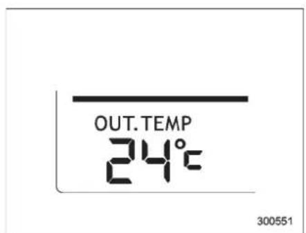
ExceptU.S.-spec.models
Theoutsidetemperatureindicatorshows theoutsidetemperatureinarangefrom -22 to 122°F (-30 to 50°C) when the ignitionswitchisinthe"ON"position.
The indicatorcangiveafalsereading underanyofthefollowingconditions.
- Whenthereistoomuchsun.
●Duringidling;whilerunningatlow speedsinatrafficjam;whentheengine isrestartedimmediatelyfollowingashut-down. - When the actual outsidetemperature falls outsidethespecified indicator range.
■ Lowoutsidetemperature warning
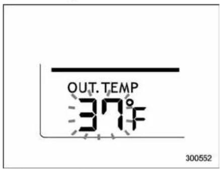
U.S.-spec.models
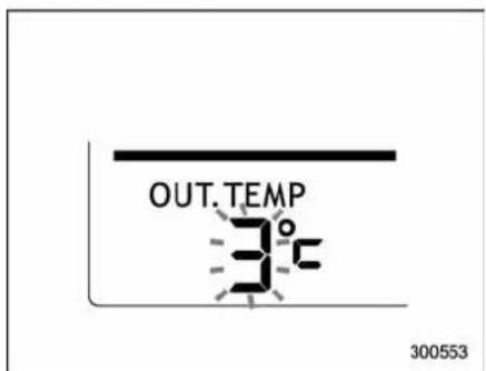
ExceptU.S.-spec.models
Whentheoutsidetemperaturedropsto
37°F (3°C) or lower, the temperature indicationflashestoshowthattheroad surfacemaybefrozen.
If the outside temperature dropsto37°F (3°C) or lower while the display is giving an indication other than the outside temperature, the display switch the outside temperature indication and flashes for 5 seconds before returning to its original indication.
If the display is already indicating an outside temperature of 37^ F ( 3^ C) or lower when the ignition switch is turned to the "ON" position, the indication does not flash.
NOTE
Theoutsidetemperatureindication maydifferfromtheactualoutside temperature.Theroadsurface freeze warningindications should betreated onlyasaguide.Besuretocheckthe conditionof theroadsurface before driving.
Multifunctiondisplay(vehicleswithoutagenuine SUBARUnavigationsystem)
NOTE
- If your vehicle is equipped with a genuineSUBARU navigation system, refer to the Owner's Manual supplementforthenavigationsystem.
- A liquid-crystal display is used in themultifunctiondisplay.Youwillfind itsindicationshardtoseeifyouwear polarizedglasses.
With the ignition switch in the "ON" position, each successive push of the "INFO" button toggle the display in the following sequence.
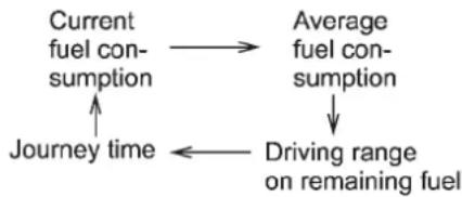
flowchart
graph TD
    A["Current fuel consumption"] --> B["Average fuel consumption"]
    B --> C["Driving range on remaining fuel"]
    C --> D["Journey time"]
Pressthe "INFO" buttonformorethan1 secondtoturnoffthedisplay. Thedisplay willturnonagainifyoupresseitherthe "INFO" button or "AUDIO" button.
■ Currentfuelconsumption
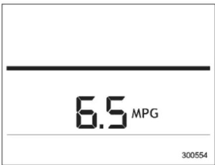
U.S.-spec.models
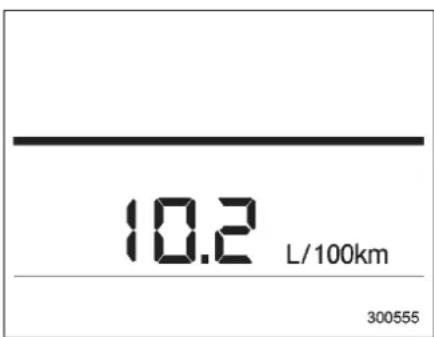
ExceptU.S.-spec.models
This indications show stherate of fuel consumption at the present moment.
-CONTINUED-
Instrumentsandcontrols
■Averagefuelconsumption
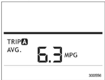
U.S.-spec.models
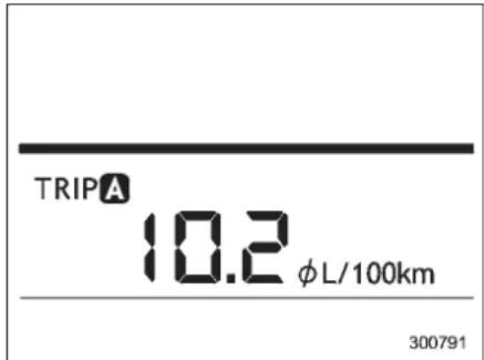
ExceptU.S.-spec.models
This indications show the average rate of fuel consumption sincethetripmeter was last reset.
Pressing the trip knob toggles the indication between the average fuel consumption corresponding to the Atripmeter indication and the average fuel consumption corresponding to the Btripmeter indication.
Wheneitherofthetripmeterindicationsis reset, the corresponding average fuel consumption value is also reset.
NOTE
- The indicated values vary in accordance with changes in the vehicle's running conditions. Also, the indicated values may differ slightly from the actual values and should thus be treated only as a guide.
- Wheneithertripmeterindicationis reset, theaveragefuelconsumption correspondingtothattripmeterindicationisnotshownuntilthevehiclehas subsequentlycoveredadistanceof1 mile(or1km).
■ Driving rangeon remaining fuel
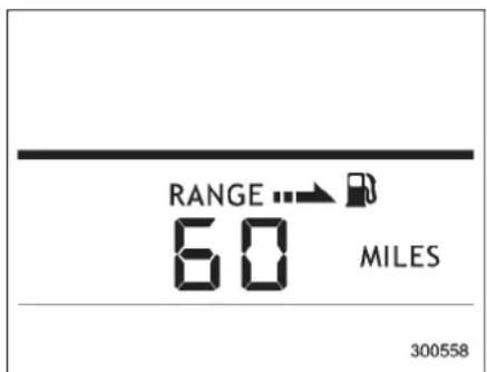
U.S.-spec.models
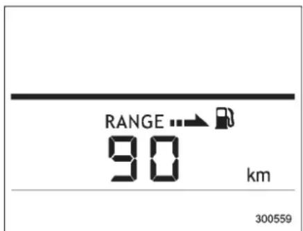
ExceptU.S.-spec.models
Thedrivingrangeindicatesthedistance
that can bedriventaking into account the amount off fuel remaining in the tank and the averagerate off fuel consumption. Whent helow fuel warning light illuminates, the driving range indication flashes for 5 seconds. (Thedisplay first switches to the driving range indication if it was originally giving some other indication.)
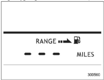
U.S.-spec.models
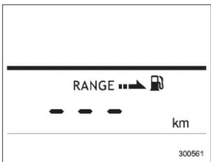
ExceptU.S.-spec.models
Ifthedrivingrangeisshownas", thereisonlyatinyamountoffuelleftinthe tank. Youmustrefuelthevehicleimmediately.
NOTE
- Thedrivingrangeonremainingfuel isonlyaguide. Theindicatedvalue maydifferfromtheactualdrivingrange onremainingfuel,soyoumustimmediatelyfillthetankwhenthelowfuel warninglightilluminates.
- Whenthelowfuelwarninglight illuminates, the display automatically shows “...” even if the currently selected indication is not forthed driving range on remaining fuel.
■Journeytime
Thejourneytimeshowsthetimethathas elapsed since the ignition switch was turnedtothe"START"position.
Thejourneytimeindicationflasheseach timeacompletehourhaselapsed.Ifthe
-CONTINUED-
displayisgivinganindicationotherthan thejourneytime,thedisplayswitchesto thejourneytime,flashesfor5seconds, andreturnstoitsoriginalindicationeach timeacompletehourhaselapsed.
NOTE
Thejourneytimeisresetwhenthe ignitionswitchisturnedtothe"LOCK" position.Itisalsoresetiftheignition switchisturnedtothe"LOCK"or "Acc"positionpriortorestartingof theengine.
Lightcontrolswitch

WARNING
Topreventbatterydischargeresultingfromaccidentallyleavingyour lightsonwhenyourvehicleis parked,thelightswitchoperates onlywhentheignitionswitchisin the"ON"position.Inanyother position,thevehicle'slightswillbe out.
If you park your vehicle on a road-side at night, use the hazard warning flash to alert the other drivers.
Thelightswitchoperatesonlywhenthe ignitionswitchisinthe"ON"position.
Headlights
301264
Toturnontheheadlights, turntheknobon theendoftheturnsignallever.
EDOE firstposition
Parkinglights, instrumentpanelillumination, taillightsandlicenseplatelightare on.

secondposition
Headlights, parkinglights, instrument panelillumination, taillights, and license platelightareon.
■ High/lowbeamchange(dimmer)
Donotholdtheleverintheflashing positionformorethanjustafew seconds.
Toflashtheheadlights,pullthelever towardyouandthenreleaseit.Thehigh beamwillremainonforaslongasyou holdthelever.Theheadlightflasherworks eventhoughthelightswitchisinthe "OFF"position.
Whentheheadlightsareonhighbeam, thehighbeamindicatorlight" ☐ "onthe combinationmeteralsoilluminates.
■Daytimerunninglightsystem

WARNING
The brightness of the illumination of the high beam headlights is reduced by the day timer running lightsystem. The light switch must always be turned to the "ED" position when it is dark outside.
Thehighbeamheadlightswillautomaticallyilluminateatreducedbrightness whentheenginehasstarted,underthe followingconditions.
- The select lever is in a position other than the "P" position.
• Theparkingbrakeisfullyreleased. - The light switch is in the "OFF" or "oo:" position.
NOTE
Whenthelightswitchisinthe“ ” EOOE position, thefrontsidemarkerlights, parking lights and license plate lights are also illuminated.
Turnsignallever
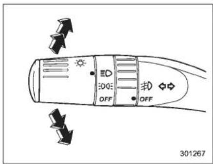
Toactivatetherightturnsignal, pushthe turnsignalleverup. Toactivatetheleft turnsignal, pushtheturnsignallever down. Whentheturnisfinished, thelever willreturnautomatically. If theleverdoes not returnaftercornering, returnthelever totheneutralpositionbyhand.
Tosignalalanechange, pushtheturn signalleverupordownslightlyandholdit duringthelanechange. Theturnsignal indicatorlightswillflashinthedirection of theturnorlanechange. Theleverwill returnautomaticallytotheneutralposition whenyoureleaseit.
Illuminationbrightnesscontrol
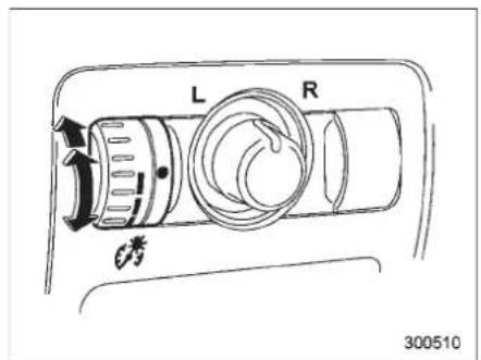
Whenthelightswitchisinthe"OFF" position,youcanadjustthebrightnessof theinstrumentpanelilluminationforbetter visibility.
The brightnessofaudio, airconditioner, multi-functiondisplay(ifequipped) and instrumentpanelilluminationautomatically dimswhenthelightswitchisinthe "oo" or "position. You can adjust brightnessoftheilluminationfor better visibility.
Tobrighten, turnthecontroldialupward. Todarken, turnthecontroldialdownward.
NOTE
When the controldialisturnedfully upward, the illumination brightness becomes the maximum and the automatic dimming function does not work at all.
Headlightbeamleveler(if equipped)
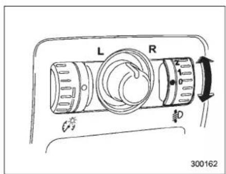
Adjusttheheadlightbeamlevelwith the followingdialpositionsaccordingtothe numberofpassengersandloadcondition.
3-30 Instrumentsandcontrols
■For5-seatermodels
| DialpositionNumberofrontseatoccupants | Numberofrearseatoccupants | Loadintheluggagecompartmentarea | Trailertowing |
| 01or20NoloadNo | |||
| 123NoloadNo | |||
| 2NotapplicableNotapplicableNotapplicableNotapplicable | |||
| 323FullloadNo | |||
| 410FullloadNo | |||
| 5NotapplicableNotapplicableNotapplicable | |||
■For7-seatermodels
| DialpositionNumber | roffrontseatoccupants | Numberof2ndseatoccupants | Numberof3rdseatoccupants | Loadintheluggagecompartmentarea | Trailertowing |
| 01or200NoloadNo | |||||
| 1 | 202NoloadNo | ||||
| 2 | 232NoloadNo | ||||
| 3 | 232FullloadNo | ||||
| 232FullloadYes | |||||
| 4 | 100FullloadNo | ||||
| 100FullloadYes | |||||
| 5 | NotapplicableNotapplicableNotapplicableNotapplicableNotapplicable | ||||
Parkinglightswitch
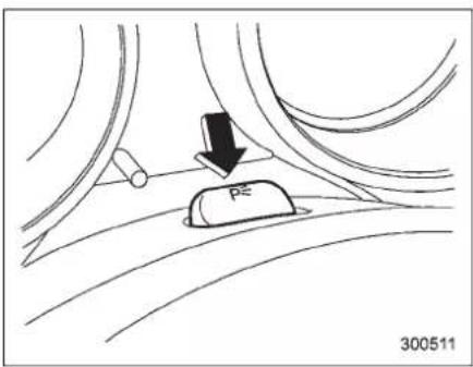
Theparkinglightswitchoperatesregardlessoftheignitionswitchposition.
Bypushingthefrontendofthisswitch, followinglightswillilluminate.
-Parkinglights
-Frontandrearsidemarkerlights
-Taillights
-Licenseplatelights
Toturnoff, pushtherearendofthe parkinglightswitch.
Avoidleavingtheselightsonforalong timebecause that will rundown the battery.
Frontfoglightswitch
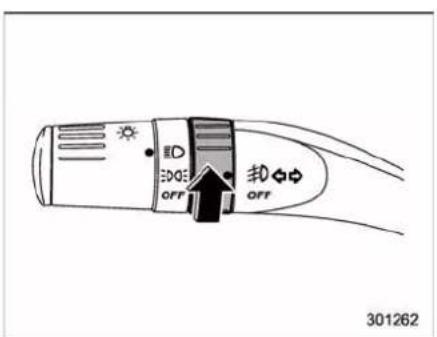
Thefrontfoglightsoperateonlywhenthe lightswitchisinthe" ID"position. However, thefrontfoglightsturnoffwhen theheadlightsareswitchedtohighbeam.
Toturnonthefrontfoglights,turnthefog lightswitchontheturnsignalleverupward tothe" #0"position.
Toturnoffthefrontfoglights,turnthe switchbackdowntothe"OFF"position.
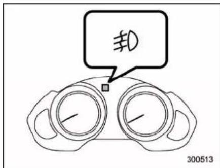
The indicator light on the combination meter will illuminate when the fog lights are illuminated.
Wiperandwasher

WARNING
Infreezingweather, donotusethe windshieldwasher until the windshield dissufficiently warmed by the defroster.
Otherwisethewasherfluidcan freezeonthewindshield, blocking yourview.

CAUTION
- Donotoperatethewashercontinuouslyformorethan10seconds,orwhenthewasherfluid tankisempty.Thismaycause overheatingofthewashermotor. Checkthewasherfluidlevel frequently,suchasatfuelstops.
- Donotoperatethewiperswhen thewindshieldorrearwindowis dry. This mayscratch the glass, damagethewiper blades and causethewipermotortoburn out. Before operating the wiper on a dry windshield or rear window, always susethewind-shieldwasher.
•Infreezingweather,besurethat thewiperbladesarenotfrozento thewindshieldorrearwindow beforeswitchingonthewipers. Attemptingtooperatethewiper withthebladesfrozentothewindowglasscouldcausenot onlythewiperbladestobe damagedbutalsothewipermotortoburnout.Ifthewiper bladesarefrozentothewindow glass,besuretooperatethe defroster,wiperdeicer(if equipped)orrearwindowdefoggerbeforeturningonthewiper.
- Ifthewipersstopduringoperationbecauseoficeorsomeother obstructiononthewindow,the wipermotorcouldburnouteven ifthewiperswitchisturnedoff.If thisoccurs,promptlystop the vehicleinasafeplace,turnthe ignitionswitchtothe"LOCK" positionandcleanthewindow glasstoallowproperwiperoperation.
- Usecleanwaterifwindshield washerfluidisunavailable.In areaswherewaterfreezesin winter,useSUBARUWindshield WasherFluidortheequivalent. Referto "Windshieldwasher
fluid"11-32.
Also, when driving the vehicle whentherearefreezingtemperatures, usenon-freezingtypewiperblades.
- Do not clean the wiper blades with gasoline or asolvent, such as paint thinner or benzine. This will caused deterioration of the wiper blades.
NOTE
- Thefrontwipermotorisprotected againstoverloadsby acircuitbreaker. Themotoroperatescontinuouslyunderanunusuallyheavyload,thecircuit breakermaytriptostopthemotor temporarily. If this happens, park your vehicleinasafeplace,turnoffthe wiperswitch,andwaitforapproximately10minutes. Thecircuitbreaker willresetitself,andthewiperswill againoperatenormally. - Cleanyourwiperbladesandwindowglassperiodicallywithawasher solutiontopreventstreaking,andto removeaccumulationsofroadsaltor roadfilm.Keepthewasherbutton depressedatleastfor1secondsothat washersolutionwillbesprinkledall overthewindshieldorrearwindow.
-CONTINUED-
- Grease, wax, insect or other material on the windshield or the wiper blades results in jerky wiper operation and streaking on the glass. If you cannot remove these streaks after operating the washer or if the wiper operation is jerky, clean the outersurface of the windshield or rear window and the wiper blades using as spongeor soft cloth with an eutral detergent or mild-abrasive cleaner. After cleaning, rinse the window glass and wiper blades with clean water. The glass is clean if no beads form the glass when your inse with water. - If you cannot eliminate the streaking even after following this procedure, replace the wiper blades with new ones. For replacement instructions, refer to "Replacement of wiper blades" 11-33.
■Windshieldwiperandwasher switches
Thewiperoperatesonlywhentheignition switch is in the "ON" or "Acc" position.
▼Windshieldwipers
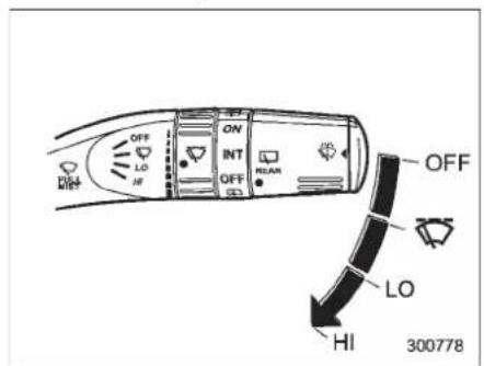
OFF:Off
Intermittent
LO:Lowspeed
HI:Highspeed
Toturnthewiperson, pushthewiper controlleverdown.
Toturnthewipersoff, return the eleverto the "OFF" position.
▼Mist(forasinglewipe)
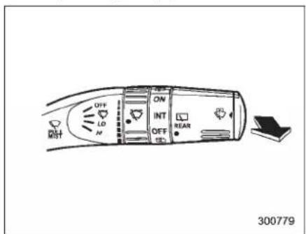
Forasinglewipeofthewipers,pullthe levertowardyou.Thewipersoperateuntil youreleasethelever.
▼Wiperintermittenttimecontrol
Whenthwiperswitchisinthe" position,turnthedialtoadjusttheoperatingintervalofthewiper.
Theoperatingintervalcanbeadjustedin ninesteps.
The intermittent operation interval varies depending on the vehicle speed in any of the adjustment steps (longer when the vehicle speed is low; shorter when the vehicle speed is high).
▼Washer
Towashtewindshield, pushthewasher button at the end of the wiper controller. The washer fluids sprays until you release the washer button. The wipers operate while you push the button.
NOTE
Thewindshieldwasherfluidwarning lightilluminateswhenthewasherfluid levelinthetankhasdroppedtothe lowerlimit.Ifthewarninglightilluminates,refillthetankwithfluid.Forthe tankrefillingmethod,referto"Windshieldwasherfluid" 11-32.
■Rearwindowwiperand washerswitch
Washer(accompaniedbywiperoperation)
ON:Continuous
INT:Intermittent
OFF:Off
:Washer
▼Rearwiper
Toturntherearwiperon,turntheknobon theendofthewipercontroleverupward to the "INT" or "ON" position.
Toturnthewiperoff, returntheknobon theendofthelevertothe"OFF"position.
With the switch turned to the "INT" position, therearwiperwilloperateintermittentlyatintervalscorrespondingtothe vehiclespeed(longerwhenthevehicle
-CONTINUED-
speedislow;shorterwhenthevehicle speedishigh).
When you subsequently movetheselect leveroftheautomatictransmissiontothe "R" position, therearwiperwillswitchto continuous operation. When you move the select leverfromthe "R" position to some other position, therearwiperwillreturn to intermittent operation.
▼Washer
Towashtherearwindowwhiletherear wiperisoperating,turntheknobonthe endofthewipercontrolleverupwardto the" 🔊"position. Thewasherfluidsprays untilyoureleasetheknob.
Towashtherearwindowwhentherear wiperisnotinuse,turntheknobonthe endofthewipercontrolleverdownwardto the" 🔍"position. Thewasherfluidsprays andthewiperoperatesuntilyourelease theknob.
Windshieldwiperdeicer
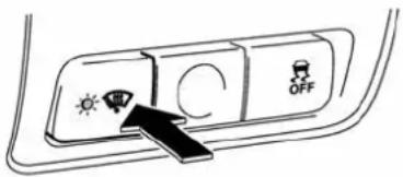
300515
Thewindshieldwiperdeiceroperatesonly whentheignitionswitchisinthe"ON" position.
Toturnonthewindshieldwiperdeicer, pushthecontrolswitch. The indicator light located on the switch illuminates while the windshieldwiperdeicer is operating.
Toturnitoff, pushthecontrolswitchagain. Italsoturnsoffwhentheignitionswitchis turned to the "Acc" or "LOCK" position.
Thewindshieldwiperdeicerwillautomaticallyshutoffafterapproximately15 minutes. If the windshieldwiper blades have been deiced completely before that time, push the control switch to turnit off. If
deicingisnotcomplete,youhavetopush thecontrolswitchtoturnitonagain.
YourSUBARUdealercansetyourwind-shieldwiperdeicertothecontinuous operationmode.ContactyourSUBARU dealerfordetails.
Oncethewindshieldwiperdeicerhas beensettothecontinuousoperation mode, it should be in the continuous operation mode at any time when the control switch is pushed to the "ON" position.
If the battery voltage drops below the permissible level, continuous operation of the windshieldwiperdeiceriscanceled and the system stops operating.

CAUTION
Topreventthebatteryfrombeing discharged, donotoperate the windshieldwiperdeicercontinuouslyforanylongerthannecessary.
NOTE
- Turnonthewindshieldwiperdeicer ifthewipersarefrozentothewindshield.
- If the windshield discovered with snow, remove the snow so that the
windshieldwiperdeicerworkseffectively.
- Whilethewindshieldwiperdeiceris inthecontinuousoperationmode,if thevehiclespeedremainsat9mph(15 km/h)orlessfor15minutes,thewindshieldwiperdeicerautomaticallystops operating.
Rearwindowdefoggerbutton
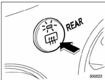
Therearwindowdefoggeroperatesonly whentheignitionswitchisinthe“ON” position.
Toturnonthedefogger, pushthecontrol switch that is located on the climate control panel. The indicator light located on the control switch illuminates while the rear window defogger is operating.
Toturnitoff, push the control switch again. It also turn so off when the ignition switch is turned to the "Acc" or "LOCK" position.
Thedefoggerwillautomaticallyshutoff afterapproximately15minutes. If therear windowhasbeenclearedcompletely
beforethattime, pushthecontrolswitch toturnitoff. If defrosting or defogging is not complete, you havetopush the control switch to turniton again.
Your SUBARUdealercan setyourrear windowdefoggertothecontinuousoperationmode.ContactyourSUBARUdealer fordetails.
Oncetherearwindowdefoggerhasbeen settothecontinuousoperationmode,it shouldbein the continuousoperation modeatanytimewhenthecontrolswitch ispushedtothe"ON"position.
If the battery voltage drops below the permissible level, continuous operation of therearwindowdefoggeriscanceled and thesystemstopsoperating.

CAUTION
- Donotusesharpinstrumentsor windowcleanercontainingabrasivestocleantheinnersurface ofthe rear window.Theymay damagetheconductorsprinted onthewindow.
- Topreventthebatteryfrombeing discharged,donotoperatethe defogger continuouslyforany longerthannecessary.
-CONTINUED-
NOTE
Theoutsidemirrordefoggeralsooperateswhiletherearwindowdefoggeris operating.
Mirrors
Alwayscheckthattheinsideandoutside mirrorsareproperlyadjustedbeforeyou startdriving.
■TypeAinsidemirror(if equipped)
natural_image
Diagram of a car frontview mirror showing rotational motion (no text or symbols)Themirrorhasadayandnightposition. Pullthetabatthebottomofthemirror towardyouforthenightposition.Pushit awayforthedayposition.Thenight positionreducesglarefromheadlights.
■TypeBinsidemirror(if equipped)
1) Rearviewimagedisplay
2)Electroniccompassdisplay
3)Autodimmingindicator
4) Multifunctionbutton
5)Photosensor
Themirrorhasthefollowingfeatures.
●Rearviewimagedisplay
●Auto-dimmingfunctionforanti-glare capability
●Electroniccompassdisplay
Youcandisplaythevariousfunctionsof thesefeaturesbasedonhowlongyou pressthemultifunctionbutton.
| Gear position | Periodof timemulti-function buttonis pressed | Function displayed |
| R(reverse) | Briefly | Rearviewdisplay ON/OFF* |
| Morethan 3seconds | Helplinesindica-tionON/OFF | |
| Except R(reverse) | Briefly | Auto-dimming functionON/OFF* |
| 3 to 6 seconds | ElectroniccompassdisplayON/OFF | |
| 6 to 9 seconds | Enterthecom-passzonesetting mode | |
| 9 to 12 seconds | Enterthecom-passcalibration mode |
*:Thesettingreturnsto"ON"asadefault settingeverytimetheignitionswitchisturnedto the"ON"position.
▼Rearviewimagedisplay
Whentheignitionswitchis"ON"andthe selectleverissetto"R",therearview cameraautomaticallydisplaystherear viewimagebehindthevehicleonthe insidemirror.
Also, the following helplines are indicated as aguidetohelpyourealizetheactual distance from the display.
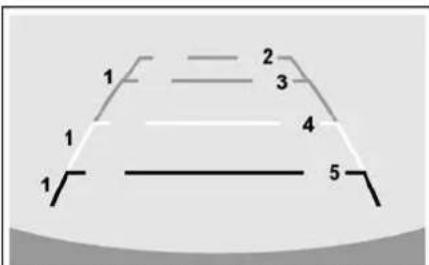
Check surroundings before backing up
601273
1) Vehiclewidthline(obliqueverticalline)
2) Approx. 10 feet (3 m) from the bumper (greenhorizontalline)
3) Approx. 6.5 feet (2 m) from the bumper (green horizontalline)
4) Approx. 3 feet (1 m) from the bumper (yellow horizontalline)
5) Approx. 1.5 feet (0.5 m) from the bumper (red horizontalline)
Thesehelplinesareremovable. To removethehelplines, perform the following procedure.
- Displaytherearviewimageonthe mirror.
- Pressthemultifunctionbuttonformore than3secondstoremovethehelplines.
Todisplaythehelplines, pressthemulti-functionbuttonformorethan3seconds.
For precautions about therearview camera and therearviewimage, referto "Rearviewcamera" 6-22.
▼Auto-dimmingfunction
Theauto-dimmingfunctionisananti-glare capabilitywhichautomatically reduces glarecomingfromheadlights ofvehicles behindyou.
By briefly pressing the multifunction button, the auto-dimming functionistoggled onoroff. When the auto-dimming function is on, the autodimming indicator light (green) willilluminate.
Even with the mirror in anti-glare mode, themirrorsurfaceturnsbrightifthe transmission is shifted into reverse. This istoensuregoodrearwardvisibilityduring reversing.
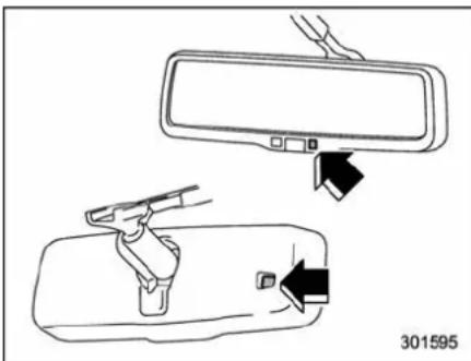
natural_image
Diagram showing a car rearview mirror and its side-mounted sensor device, both without any text or symbols.Themirrorhasaphotosensorattachedon boththefrontandbacksides. Usecare nottocoverthesensorswithstickers, or othersimilaritems. Periodicallywipethe sensorscleanusingapieceofdrysoft cottonclothoranapplicator.
NOTE
Whencleaningthemirror, useapaper towelorsimilaritemdampenedwith glasscleaner. Donotsprayglass cleanerdirectlyonthemirrorsurface. Bydoingso, thesprayedglasscleaner couldentertheinsideofthemirror housing. That may cause amalfunction inthemirror.
▼Electroniccompassdisplay
Bypressingthemultifunctionbuttonfor3 to6seconds,thecompassdisplayis toggledonoroff.Whenthecompass displayison,anilluminatedcompass readingwillappearonthemirror.
Using the electronic compass properly, the following compass zone adjustment and compass calibration will be necessary.
- Thecompasszonehasbeensetto zone"8"atthetimeofshipmentfromthe factory. Refertothe"Compasscalibration zones"map,whichisattachedtotheend ofthismanualtoverifythatthecompass zonesettingiscorrectforyourgeographicallocation.
- Pressandholdthemultifunctionbuttonfor6to9seconds,andthenreleaseit. Thezonenumberwillbedisplayed.
- Pressthemultifunctionbuttonrepeatedlytcyclethedisplaythroughall possiblezonesettings.Stopcyclingwhen thecorrectzonenumberforyourlocation isdisplayed.
- Releasingthebuttonfor3secondswill exitthezonesettingmode.
Compasscalibration
- Foroptimumcalibration, switchoffall nonessential electrical accessories (rear window defogger, heater/air conditioning system, spotlight, etc.) and ensure all doors areshut.
- Drivetoanopen, levelareaaway from largemetallicobjectorstructures and make certain the ignitionswitchis in the "ON" position.
- Pressandholdthemultifunctionbuttonfor9to12seconds,andthenrelease it.Thecompasswillenterthecalibration mode,then"C"anthedirectionwillbe displayed.
- Driveslowlyinacircleuntil"C" disappearsfromthedisplay.Drivingin twoorthreecirclesmightbenecessary. Thecompassisnowcalibrated.
- Furthercalibrationmaybenecessary shouldoutsideinfluencescausethecompasstoreadinaccurately.Youwillnotice any outside influence if the compass tends toreadinonlyoneparticulardirection.Shouldyouencounterthissituation, return tostep1oftheaboveprocedureand recalibratethecompass.
■TypeCinsidemirror(if equipped)
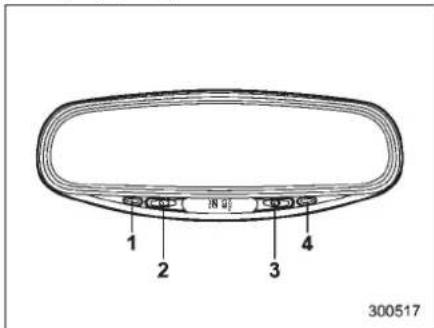
1) Leftbutton
2)Autodimmingindicator
3)Photosensor
4)Rightbutton
This mirror has an anti-glare feature which automatically reduces glare coming from headlight of vehicles behind you. It also contains built-in compass.
●Bypressingandreleasingtheleft button, theautomaticdimmingfunctionis toggledonoroff. When the automatic dimmingfunctionison, the autodimming indicatorlight(green) located to otheright of the button willilluminate.
●Bypassingandreleasingtheright button, thecompassdisplayistoggledon
oroff. Whenthecompassison, an illuminatedcompassreading will appear in the lower part of them mirror.
Evenwiththemirrorinanti-glaremode, themirrorsurfaceturnsbrightifthe transmissionisshiftedintoreverse. This istoensuregoodrearwardvisibilityduring reversing.
▼Photosensors
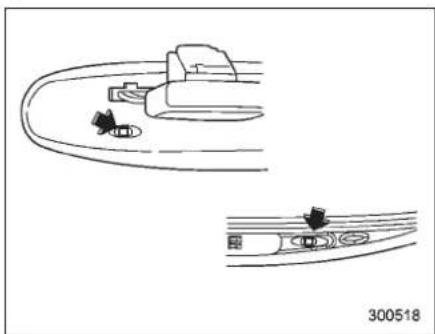
natural_image
Diagram showing two curved road scenarios with directional arrows, no text or symbols presentThemirrorhasaphotosensorattachedon boththefrontandbacksides.lftheglare fromtheheadlightsofvehiclesbehindyou strikethemirror,thesesensorsdetectit andmakethereflectionsurfaceofthe mirrordimmertohelpprevent youfrom beingblinded.Forthisreason,usecare nottocoverthesensorswithstickers,or othersimilaritems.Periodicallywipethe
sensorscleanusingapieceofdrysoft cottonclothoranapplicator.
▼Compasscalibration
- Foroptimumcalibration, switchoffall nonessential electrical accessories (rear windowdefogger, heater/air conditioning system, spotlight, etc.) and ensure all doorsareshut.
- Drivetoanopen, levelareaaway from largemetallicobjectsonstructures and make certain the ignitionswitchisin the "ON" position.
- Press and hold the left button for 3 secondsthenrelease, and the compass will enter the calibration mode. "CAL" and direction will be displayed.
- Driveslowlyinacircleuntil"CAL" disappearsfromthedisplay(approximatelytwoorthreecircles).Thecompass isnowcalibrated.
- Furthercalibrationmaybenecessary shouldoutsideinfluences cause themirror to read inaccurately. You will know that thishasoccurredifyourcompassbegins toreadinonlylimiteddirections.Should youencounterthissituation,returntostep oneof theabove procedureand recalibratethemirror.
-CONTINUED-
3-42 Instrumentsandcontrols
- The zonesetting is factory preset to Zone8. Referto the "Compass calibration zone" map attached to the end of this manual to verify that the compass zone setting is correct for your geographical location.
- Pressandholdtherightbuttonfor3 secondsthenrelease, andtheword "ZONE" willbriefyappearandthenthe zonenumberwillbedisplayed.
- Presstheright-handbutton repeatedly tocyclethedisplaythroughallpossible zonesettings.Stopcyclingwhenthe correctzonesettingforyourlocationis displayed.
- Releasing the button for 3 second will exit the zonesetting mode.
■Outsidemirrors
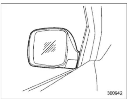
natural_image
Line drawing of a car side mirror mounted on a vehicle, showing no text or symbols▼Convexmirror(passengerside)
WARNING
Objectslooksmallerinaconvex mirrorandfartherawaythanwhen viewedinaflatmirror.Donotuse theconvexmirrortojudgethe distanceofvehiclesbehindyou whenchanginglanes.Usetheinside mirror(orglancebackwards)to determinetheactualsizeanddistanceofobjectsthatyouviewin convexmirror.
▼Remotecontrolmirrorswitch
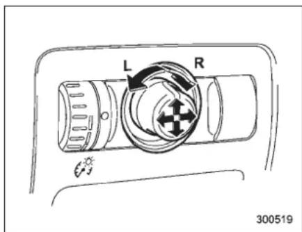
Theremotecontrolmirrorsoperateonly whentheignitionswitchisinthe"ON"or "Acc"position.
- Turntheknobtothe“L”sidetoadjust theleft-handmirrorortothe“R”sideto adjusttheright-handmirror.
2.Movetheknobinthedirectionyou wanttomovethemirror. - Return the knob to the neutral position to prevent unintentional operation.
Themirrorscanalsobeadjusted manually.
▼Outsidemirrordefogger
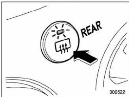
Theoutsidemirrordefoggersharesthe controlswitchwiththerearwindowdefogger. Therefore, theoutsidemirrordefoggeralwaysoperateswiththerear windowdefogger.
If therearwindowdefoggerissettothe continuousoperationmode,theoutside mirrordefoggeralsofollowsthecontinu-oussetting.
Fordetails, referto "Rearwindowdefoggerbutton" 3-37.

CAUTION
Topreventthebatteryfrombeing discharged, donotoperatethedefoggercontinuouslyforanylonger
thannecessary.
▼Powerfoldingmirrorswitch(if equipped)
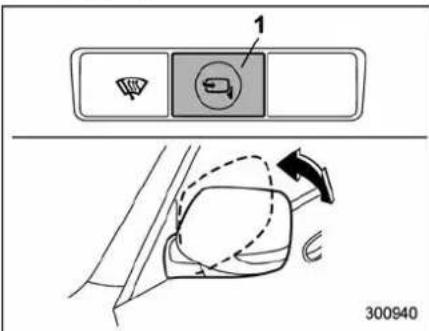
1) Powerfoldingmirrorswitch
The power folding mirrors witch operates only when the ignitions switch in the "ON" or "Acc" position.
Tofoldtheoutsidemirrors, pushthepower foldingmirrorswitch. Tounfoldthemirrors, pushtheswitchagain.
NOTE
- Whenthetemperatureislow,the outsidemirrorsmaystopduringoperation.Pushtheswitchagain.Whenthe outsidemirrorsdonotworkbyswitch operation,movethemseveraltimes
manually.This makesit possibleto operatethembyswitchoperation.
- Whenyouoperatethepowerfolding mirrorswitchcontinuously, it may temporarily stop working. This is not amalfunction. Operateitagainafter waiting for short period of time.
- When you unfold the outsidemirrors manually, them mirrors may become unstable. Besuretounfold them mirrors by switch operation. If the outside mirrors are still unstable, fold the mirrors again manually and then unfold them by switch operation.
Instrumentsandcontrols
Tiltsteeringwheel

WARNING
Donotadjustthesteeringwheeltilt positionwhiledriving. This may cause lossof vehicle control and result in personal injury.
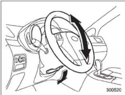
natural_image
Diagram of a car interior showing steering wheel and directional arrows (no text or symbols)- Adjust theseat position. Referto "Frontseats" 1-2.
- Pullthetiltlockleverdown.
3.Movethesteeringwheeltothedesired level. -
Pulltheleveruptolockthesteering wheelinplace.
-
Makesure that the steering wheel is securely locked by moving it up and down.
Horn
natural_image
Diagram of a car steering wheel and dashboard (no text or symbols)Tosoundthehorn, pushthehornpad.
Climate control
Ventilator....4-2
Airflow....4-2
Ventilator....4-4
Automaticclimatecontrolsystem....4-5
Controlpanel....4-5
Rearairconditioner(ifequipped)....4-8
Temperaturesensors....4-9
Operatingtipsforheaterandair
conditioner....4-10
Cleaningventilatorgrille....4-10
Efficientcoolingafterparkingindirect sunlight....4-10
Lubricationoilcirculationintherefrigerant circuit....4-10
Checkingairconditioningsystembeforesummer season....4-10
Coolinganddehumidifyinginhighhumidity and lowtemperatureweatherconditions....4-10
Airconditionercompressorshut-offwhenengine isheavilyloaded....4-10
Refrigerantforyourclimatecontrolsystem......4-10
Air filtration system 4-11
Replacingtheairfilter....4-11
4-2Climatecontrol
Ventilator
Airflow
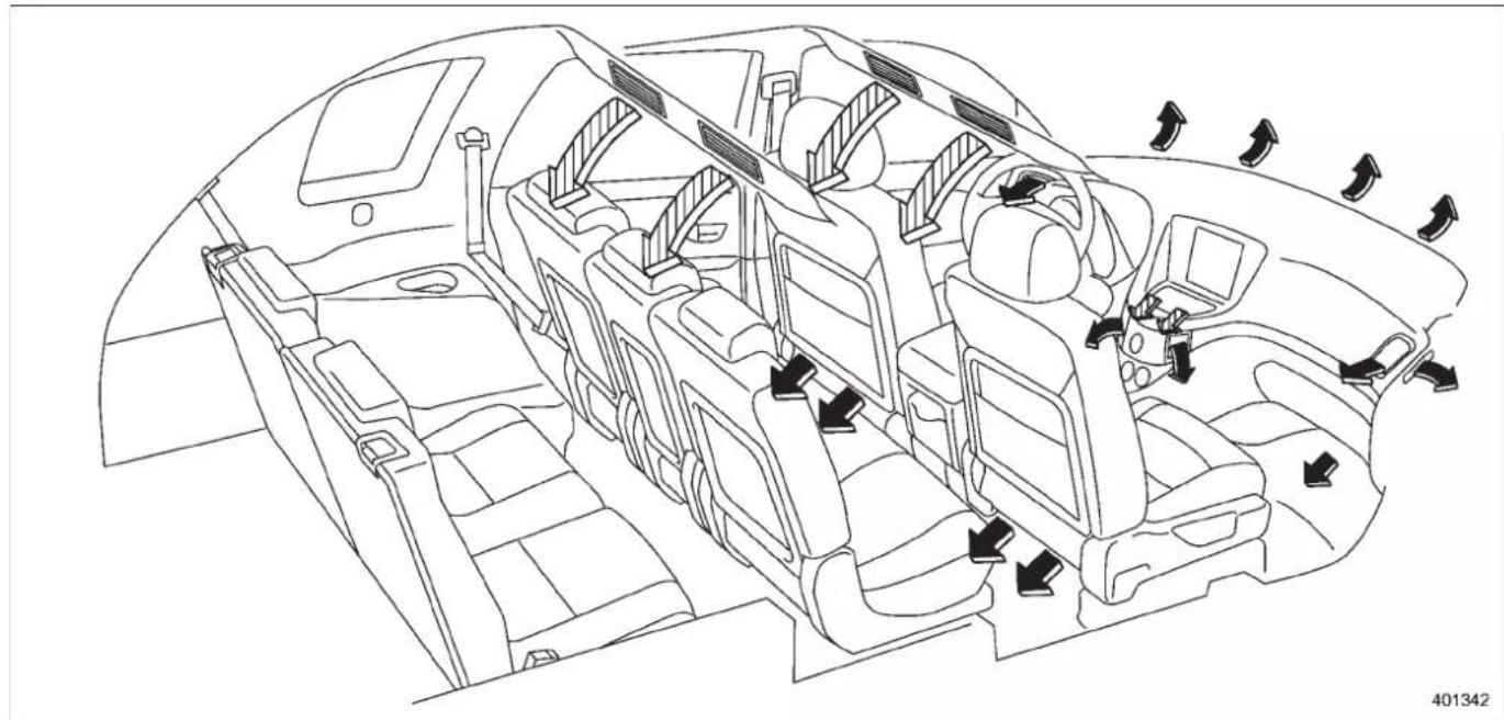
natural_image
Line drawing of a car interior showing airflow direction arrows (no text or symbols)Ventilatorandairflow
→:Standard
: Ifequipped
▼Airflowmodeselection
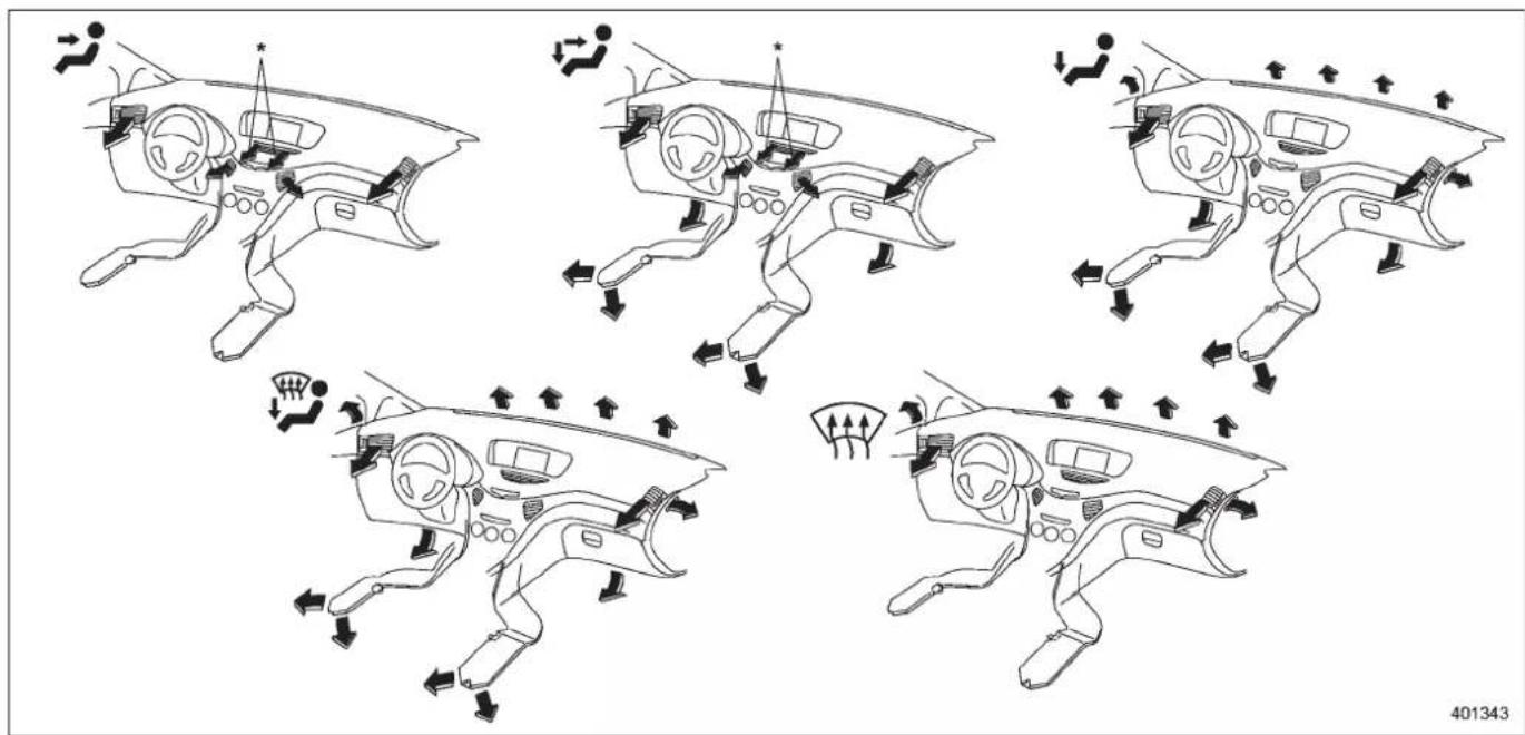
*: Ifequipped
-CONTINUED-
4-4Climatecontrol
Ventilator
▼Centerventilators
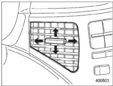
natural_image
Diagram of a car's side window with directional arrows and a grid-patterned area, no readable text or symbolsMovethetabupanddownorrightandleft toadjusttheflowdirection.
▼Sideventilators
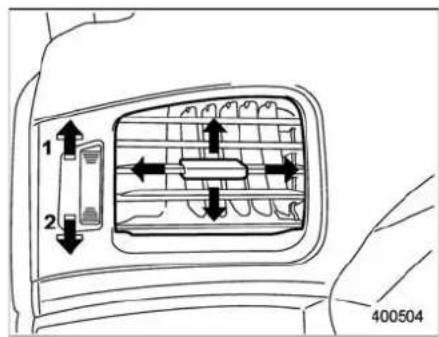
1) Open
2)Close
Movethetabupanddownorrightandleft toadjusttheflowdirection.
Toopentheventilator,turnthesidegrille open/closewheelupward.
Tocloseit,turnthewheeldownward.
▼Rearventilators(ifequipped)
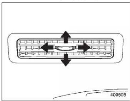
natural_image
Diagram of a vehicle rearview system with bidirectional arrows indicating flow or movement (no text or symbols)Movethetabupanddownorrotateright andlefttoadjusttheflowdirection.
Automaticclimatecontrol system
NOTE
- Operatetheautomaticclimatecontrolsystemwhentheengineisrunning.
•Theblowerfanrotatesatalow speedwhentheenginecoolanttemperatureislow.
Forefficientdefoggingordehumidifyingincoldweather, press the "A/C" button.
- Evenwhencoolingisnotnecessary, settingthetemperaturemuchlower thanthecurrentoutletairtemperature turnsontheairconditionercompressorautomaticallyandtheindicator lightonthe"A/C"buttonilluminates. - 7-seatermodelseachhavearearair conditioner. Thefanspeedoftherear airconditionercanbeadjusted,but otheradjustments(outletairtemperature,airdistribution,etc.)arenot possiblefortherearairconditioner. Fordetails,referto"Rearairconditioner"4-8.
The automaticclimatecontrolsystem automaticallycontrolsoutletairtemperature,fanspeed,airflowdistribution,air inletcontrol,andairconditionercompressoroperation.Itactivateswhenthe
"AUTO"buttonispressed, and is used to maintain a constant, comfortable climate within the passenger compartment.
Thetemperaturecanbesetwithinarange of65to85°F(18to32°C).
Controlpanel
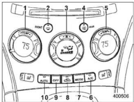
1) Temperature control dial(driver's side)
2) Defrosterbutton
3)Fanspeedcontroldial
4) Rearwindowdefoggerbutton (Referto "Rearwindowdefoggerbutton" 3-37.)
5) Temperature control dial (passenger's side)
6) Airconditionerbutton
7) Airflowmodeselectionbutton
8) Airinletselectionbutton
9)OFFbutton
10) AUTObutton
▼AUTObutton
AUTOmodeoperation:
When the "AUTO" button is pressed, the indicator light on the button illuminates. In this state, fanspeed, airflow distribution, air inlet control, and air conditioner compressor operation are automatically controlled.
Manualmodeoperation:
If you operate any of the button on the control panel other than the "OFF" button and temperature controldial during automatic mode operation, the indicator light will turn off. You can then manually control the system desired using the button you operated.
TochangethesystembacktotheAUTO mode, pressthe "AUTO" button.
-CONTINUED-
4-6Climatecontrol
▼OFFbutton
TheAutomaticClimateControlsystem turnsoff(theairconditionercompressor andfanturnoff)whenthe"OFF"buttonis pressed.
When the "OFF" button is pressed, the outside air introduction mode (air inlet selection OFF) is automatically selected.
▼Temperaturecontroldial
Driver'sside
Passenger'sside
Itispossibletomakeseparatetemperaturesettingsforthedriver'ssideand
passenger's side. Each temperature setting is shown on the display. With the dialset at your desired temperature, the system automatically adjusts the temperature of air supplied from the outlet such that the desired temperature is achieved and maintained.
Turningthedialcounterclockwise and releasingitreducesthetemperatureby 1°F (0.5°C). Turning the dial clockwise and releasingitincreasessthetemperature by 1°F(0.5°C). Holdingthedialineither turnedpositioncausessthetemperatureto changecontinuously.
With the minimum temperature set, the system gives maximum cooling performance. With the maximum temperature set, the system gives maximum heating performance.
▼-Defrosterbutton
Todefrostordehumidifythewindshield andfrontdoorwindows, pushthedefrosterbutton" "".Whenthe" button is pushed, the indicatorlightonthebutton illuminates and the following operation is performed.
- The outside air is drawn into the passenger compartment and the airflow is directed toward the windshield and the frontdoor windows.
●The airconditionercompressor automatically operate to quickly defog the windshield. However, the indicator light on the air conditioner button will not illuminate.
Aftereliminatingthefogging from the windshield, return theclimatecontrol
systemtotheAUTOmodebypushing the "AUTO"buttonorturnoffbypushing the "OFF"button.
Alternatively, pushthe "buttonagain toreturnthesystem to the setting that was selected before you activated the defroster.
▼ Fanspeedcontroldial
natural_image
Circular diagram with directional arrows and a small grid of icons inside, no readable text or symbolsThe fan speed control dial has 7 positions: AUTOposition and 6 different fanspeed positions.
Thefanspeedisshownonthecenterof thedial.
With the fanspeed controldial in the AUTO position, the fanspeed changes automatically corresponding the various conditions: air temperature inside and outside of the passenger's compartment,
intensityofthesunlight,etc.
▼ A/C-Airconditionerbutton
If the windshield start to fog when the climate control system is operated in the AUTO mode, push the air conditioner buttontode fog and dehumidify.
Whenthisbuttonispushed, theair conditionercompressorturnsonandthe indicatorlightonthebuttonilluminates. After eliminating the fogging from the windshield, setthesystembacktothe AUTO mode by pushing the "AUTO" button.
NOTE
Theairconditionercompressordoes notoperatewhentheoutsideairtemperature is below 32°F (0°C).
-CONTINUED-
4-8Climatecontrol
▼Airflowmodeselectionbutton
Select the desired airflow mode bypassing the airflow modes selection button. The selected airflow mode is shown on the center of the medial.
(Ventilation): Airflowsthrough the instrumentpaneloutlets.
(Bi-level): Airflowsthroughtheinstrumentpaneloutletsandthefootoutlets.
(Heat):Airflowsthroughtheinstrument paneloutlets, thefootoutlets, and some throughthewindshielddefrosteroutlets.
(Heat-def):Airflowsthroughtheinstrumentpaneloutlets,thewindshielddefrosteroutlets,andthefootoutlets.
▼Airinletselectionbutton
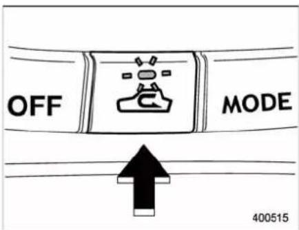
ONposition(recirculation): Interiorairis recirculatedinsidethevehicle. Push the airinletselectionbuttontotheONposition for fast cooling with the air conditioner or when driving on a dusty road. The indicator light will illuminate.
OFFposition(outsideair):Outsideairis drawnintothepassengercompartment. Pushtheairinletselectionbuttonontothe OFFpositionwhentheinteriorhascooled toaccomfortabletemperatureandtheroad isnolongerdusty. Theindicatorlightwill turnoff.

WARNING
ContinuedoperationintheONpositionmayfogupthewindows.Switch
totheOFFpositionassoonasthe outsidedustyconditionclears.
NOTE
Whendrivingonadustyroadorbehind avehiclethatemitsunpleasantexhaust gases,settheairinletselectionbutton totheONposition.
Fromtimetotime, return the air inlet selection button to the OFF position to draw outside air into the passenger compartment.
■ Rearairconditioner(if equipped)
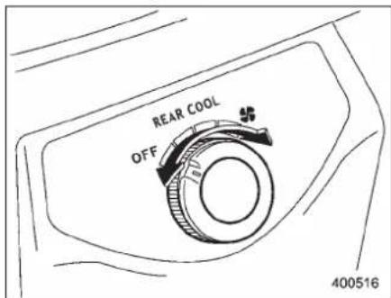
Therearairconditionerblowscoolairout oftherearventilatorswhilethe"A/C"
buttononthecontrolpanelisinthe"ON" position. Thefanspeedoftherearair conditionercanbeadjustedusingtherear airconditionerdialbehindthecenter console. Thefanspeedcanbeadjusted infourstepsbyturningthedial. Turnthe dialtothe"OFF"positiontostopthefan.
NOTE
- Whenthe“A/C”buttonisinthe “OFF”positionandwhenthe“A/C” indicatoris notilluminated during AUTOmodeoperation, theairconditioner compressordoesnotoperate, meaning that the system merely blows uncooled air out of the ventilators.
- Theoutletairtemperatureoftherear airconditionercannotbeadjusted.
- Therearairconditionercannotbe usedasaheater.
■ Temperaturesensors
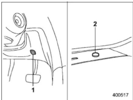
The automaticclimatecontrolsystem employsseveral sensors. Thesesensors aredelicate. If they are treated incorrectly and became damaged, the system may not be able to control the interior temperature correctly. To avoid damaging the sensors, observ the following precautions.
– Donotsubjectthesensorstoimpact.
- Keepwaterawayfromthesensors.
- Donotcoverthesensors.
1) Interiorairtemperaturesensor
2) Solarsensor
Thesensorsarelocatedasfollows.
- Solar sensor: beside windshield defrostergrille
- Interiorairtemperaturesensor:onthe side of the driver-side part of the center panel
- Outsidetemperaturesensor:behind frontgrille
Operatingtipsforheaterand airconditioner
■Cleaningventilatorgrille
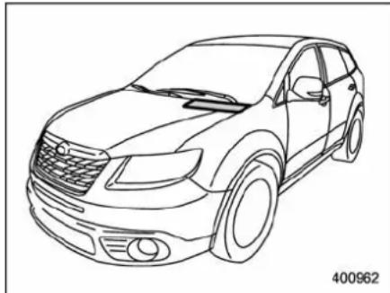
natural_image
Line drawing of a sedan car with headlights and grille (no text or symbols)Alwayskeepthefrontventilatorinletgrille freeofsnow,leaves,orotherobstructions toensureefficientheatinganddefrosting. Sincethecondenserislocatedinfrontof theradiator,thisareashouldbekeptclean becausecoolingperformanceisimpaired byanyaccumulationofinsectsandleaves onthecondenser.
■ Efficientcoolingafterparking indirectsunlight
Afterparkingindirectsunlight,drivewith thewindowsopenforafewminutesto allowoutsideairtocirculateintothe
heatedinterior. This results in quicker cooling by the air conditioner. Keep the windows closed during the operation of the air conditioner for maximum cooling efficiency.
■ Lubricationoilcirculationin therefrigerantcircuit
Operatetheairconditionercompressorat alowenginespeed(atidleorlowdriving speeds)afewminuteseachmonthduring theoff-seasontocirculateitsoil.
■ Checkingairconditioning systembeforesummerseason
Checktheairconditionerunitforrefriger-antleaks,hoseconditions,andproper operationeachspring.Havetheairconditioning system checked by your SUBARUdealer.
■Coolinganddehumidifyingin highhumidityandlowtemperatureweatherconditions
Undercertainweatherconditions(high relativehumidity,lowtemperatures,etc.)a smallamountofwatervaporemission fromtheairoutletsmaybenoticed.This conditionisnormalanddoesnotindicate anyproblemwiththeair conditioning
system.
■ Airconditionercompressor shut-offwhenengineis heavilyloaded
Toimproveaccelerationandgasmileage, theairconditionercompressorisdesigned totemporarilyshutoffduringairconditioneroperationwhenevertheaccelerator isfullydepressedsuchasduringrapid accelerationorwhendrivingonasteep upgrade.
■Refrigerantforyourclimate controlsystem
Yourairconditionerusesozonefriendly refrigerantHFC134a. Therefore, themethodofadding, changingorcheckingthe refrigerantisdifferentfromthemethodfor CFC12(freon).ConsultyourSUBARU dealerforservice.Repairsneededasa resultofusingthewrongrefrigerantare notcoveredunderwarranty.
Airfiltrationsystem
Replacethefilterelementaccordingtothe replacementscheduleshowninthefollowing. This schedules should be followed to maintain the filter's dust collection ability. Underextremely dusty conditions, the filters should be placed more frequently. It is recommended that you have your filter checked or replaced by your SUBARUdealer. For replacement, we recommend the use of a genuine SUBARUairfilterkit.
Replacementschedule:
Every15monthsor15,000miles(24,000 km)whichevercomesfirst
■Replacingtheairfilter
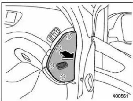
natural_image
Diagram of a car interior showing a highlighted vehicle seat with buttons and a numbered label (400561) at the bottom right corner.- Removetheinstrumentpanelside cover.
NOTE
Theinstrumentpanelsidecoverisheld inplacewithfourpins.
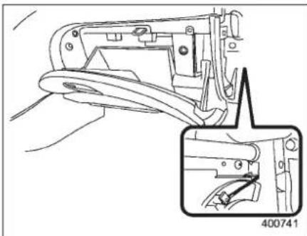
natural_image
Technical line drawing of a mechanical component with an inset detail showing a detail view (no text or symbols)2.Unhookthestrap.
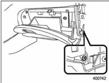
natural_image
Technical line drawing of a mechanical component with an inset detail showing a detail view (no text or symbols)- Removethegloveboxbydetaching theoneclipontheside.
-CONTINUED-
4-12Climatecontrol
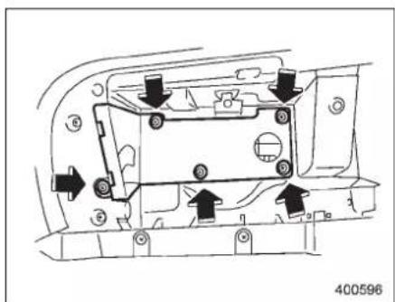
natural_image
Technical diagram of a mechanical component with arrows indicating assembly or movement (no text or symbols)- Removetheairfiltercoverbydetachingthefiveclips.
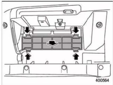
natural_image
Technical diagram of a vehicle chassis showing internal components and directional arrows (no text or symbols)- Unhook the air filter and draw out.
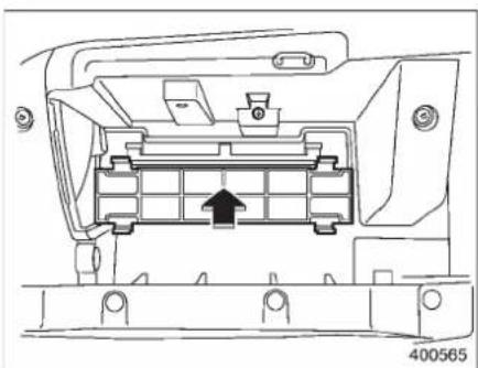
natural_image
Technical line drawing of a mechanical component with internal structure and mounting holes (no text or symbols)-
Replacetheairfilterwithanewone.
-
Install the air filter cover.
8.Installtheglovebox.
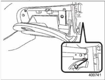
natural_image
Technical line drawing of a mechanical component with an inset detail showing a detail view (no text or symbols)- Attachthestraptothehook.
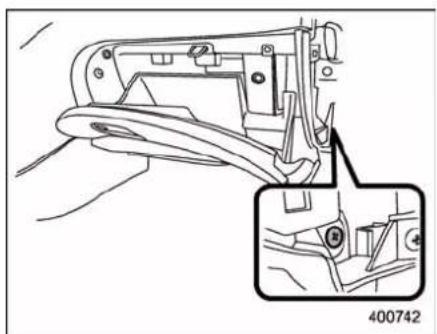
natural_image
Technical line drawing of a mechanical component with an inset detail showing a detail (no text or symbols)- Secure the glove box with the one clip.
- Install the instrument panelside cover
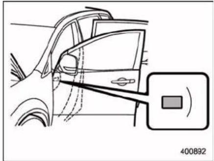
natural_image
Line drawing of a car's side profile with a highlighted sensor or sensor component (no text or symbols)12.Labelinstallation Attachthecautionlabeltothedriver's door.

CAUTION
ContactyourSUBARUdealerifthe followingoccurs,evenifitisnotyet timetochangethefilter.
-Reductionoftheairflowthrough thevents.
-Windshieldgetseasilyfoggedor misted.
NOTE
Thefiltercaninfluencetheairconditioning, heating and defroster performance if not properly maintained.
| -1.5 | -1.5 | -1.5 | -1.5 |
Audio
Antennasystem....5-2
Printedantenna....5-2
FMreception....5-2
Installationofaccessories....5-2
Audioset....5-3
TypeAudioset....5-3
TypeBaudioset....5-3
TypeAaudioset(ifequipped)....5-4
Radiooperation....5-4
Compactdiscplayeroperation....5-10
TypeBaudioset(ifequipped)....5-15
Radio operation 5-15
BuiltinCDchangeroperation.... 5-21
Audiocontrolbuttons....5-26
MODE button.... 5-26
Auxiliaryinputjack....5-28
RearSeatEntertainment(RSE)system
operation(ifequipped)......5-29
Precautionstoobservewhenhandlinga
compactdisc....5-29
5-2Audio
Antennasystem
Printedantenna

CAUTION
Donotusesharpinstrumentsor windowcleanercontainingabrasivestocleantheinnersurfaceof thewindowonwhichtheantennais printed.Doingsomaydamagethe antennaprintedonthewindow.
natural_image
Line drawing of a car rear view with no text or symbolsTheantennaisprintedontheinner surfaceoftherearwindowglass.
NOTE
Antennaperformancewilldeteriorate significantlyifyyouapplytintingfilmor
anyothermaterialovertheantenna portionoftherearwindowglass.
■FMreception
Although FMisnormallystaticfree, receptioncanbeaffectedbythesurroundingarea,atmosphericconditions,station strengthandtransmitterdistance.Buildingsorotherobstructionsmaycause momentarystatic,flutterorstationinterference.Ifreceptioncontinuestobe unsatisfactory, switch to a stronger station.
NOTE
Ifacellphoneisplacedneartheradio, itmaycausetheradiotoemitnoise whenitreceivescalls. Thisnoisedoes notindicatearadiomalfunction.
Installationofaccessories
AlwaysconsultyourSUBARUdealer beforeinstallingacitizenbandradioor othertransmittingdeviceinyourvehicle. Suchdevicesmaycausetheelectronic controlsystemtomalfunctioniftheyare incorrectlyinstalledoriftheyarenot suitedforthevehicle.
Audioset
YourSUBARUmaybeequippedwithone ofthefollowingaudiosets.Seethepages indicatedinthissectionforoperating details.
■TypeAaudioset
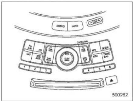
●Radiooperation:refertopage5-4
- CD(compactdisc)playeroperation: refertopage5-10
■TypeBaudioset
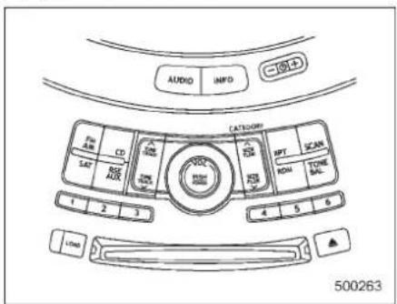
●Radiooperation:refertopage5-15
●Built-inCDchangeroperation:referto page5-21
5-4Audio
TypeA audioset(ifequipped)
The audio set will operate only when the ignition switch is in the "Acc" or "ON" position.
Radiooperation
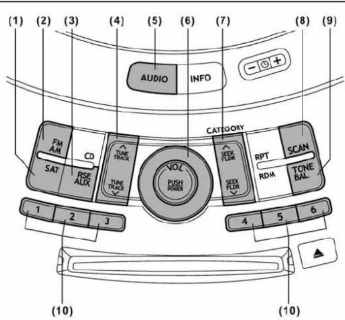
500264
(1)Satelliteradiomodebutton
(2)FMAMmodebutton
(3)AuxiliaryaudiounitandRearseat entertainmentselectionbutton
(4) Tuningbutton
(5)AUDIObutton
(6)Powerswitch,volumecontroldial
(7)Seekbutton
(8)Scanbutton
(9)ToneandBalancebutton
(10)Presetbutton
▼Powerswitchandvolumecontrol
Thedial(6)isusedforbothpower(ON/OFF)andvolumecontrol.Theradiois turnedONandOFFbypushingthedial andthevolumeiscontrolledbyturningthe dial. Thedialcanalsobeusedfortone andbalanceadjustment.
▼Toneandbalancecontrol
The volume control dial(6) normally functions as a volume control. This dial becomes a control for Bass, Midrange, Treble, Faderor Balance when you select the appropriate tone and balance control mode.
Choosedesiredvolumelevelforeach modebyturningthevolumecontroldial. Thecontrolfunctionreturnstovolume controlmodeafter approximately5 seconds.
Audio5-5
▽Tochangetoneandbalancecontrol modes
Eachbriefpressofthe"TONEBAL" button(9)changescontrolmodesinthe followingsequencestartingfromvolume controlmode.(Whentheradioisfirst turnedon,thecontrolmodeisinthe volumecontrol.)
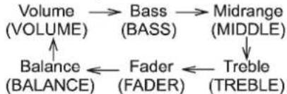
flowchart
graph TD
    A["Volume (VOLUME)"] --> B["Bass (BASS)"]
    B --> C["Midrange (MIDDLE)"]
    C --> D["Treble (TREBLE)"]
    D --> E["Fader (FADER)"]
    E --> F["Balance (BALANCE)"]
    F --> A
The "TONE BAL" button is used for selecting the following control modes.
-CONTINUED-
5-6Audio
| Controlmode(rangeofle-vels) | 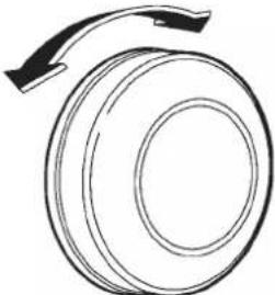 500204 500204 | |
| TurncounterclockwiseTurnclockwise | ||
| Basscontrol(-6to+6)ForlessbassoundFormorebassound | ||
| Midrangecontrol(-6to+6)ForlessmidrangesoundFormoremidrangesound | ||
| Treblecontrol(-6to+6)ForlesstreblesoundFormoretreblesound | ||
| Fadercontrol(R9toF9) | Toincreaserearspeakervolumeanddecreasefrontspeak-ervolume | Toincreasefrontspeakervolumeanddecreaserearspeakervolume |
| Balancecontrol(L9toR9) | Toincreaseleftspeakervolumeanddecreaserightspeakervolume | Toincreaserightspeakervolumeanddecreaseleftspeakervolume |
| Volumecontrol(0to40) | Forlessvolume | Formorevolume |
| AUXvolumecontrol*(0to40) | Forlessvolume | Formorevolume |
*:OnlywhenanAUXaudioproductisconnected.
▼ FM/AMradio
▽FM/AMselection button
Push the "FM AM" button (2) when the radioisoff toturnonthe radio.
Push the "FM AM" button when the radio isontoselectFM1, FM2orAMreception.
▽Stereoindicator
The stereo indicator "ST" will illuminate whenanFMstereobroadcastisreceived.
Manualtuning
Pressthe "∧" sideofthe "TUNETRACK" button(4)toincreasethetuningfrequency and press the ∨ side of the button to decreaseit.
Each time the button is pressed, the frequencyinterval canbe changedbetween 10 kHz in the AM mode and 0.2 MHzinthe FMmode.
If you hold down the “^” side of the button, the tuning frequency will increase continuously, and if you holldownthe “ ∨” side of the button, the tuning frequency will decrease continuously. Releasethe button when your desired frequency is reached.
NOTE
While you are holding downeitherside of the "TUNE TRACK" button, the tuning frequency will not stop changing even if the frequency of available station is reached.
∇Seektuning
If you press the “∧” or “side of the “SEEKFLDR” button(7), theradiowill automatically search for are ceivable station and stop at the first one it finds. This function may not be available, however, when radiosignals are weak. Insuch asituation, perform manual tuning to select the desired station.
Automatictuning(SCAN)
Pressthe"SCAN"button(8)tochangethe radiototheSCANmode.Inthismode,the radioscansthroughtheradiobanduntila stationisfound.Theradiowillstopatthe stationfor5secondswhiledisplayingthe frequency,afterwhichscanningwillcontinueuntiltheentirebandhasbeen scannedfromthelowendtothehigh end.Pressthe"SCAN"buttonagain to canceltheSCANmodeandtostoponany displayedfrequency. Pressthe"^"or"sideofthe"SEEK FLDR"button(7)againtocancelthescan modeandtostoponanydisplayed
frequency.
When the "SCAN" button is pressed for automatic tuning, stations are scanned in the direction of flow frequenciest high frequencies only.
Automatic tuning may not function properly if the station reception is weakened by distance from the station or proximity to tall buildings and hills.
▼Selectingpresetstations
Presettingastationwithapresetbutton (10)allowsyoutoselectthatstationina singleoperation.Uptosix,AM,FM1and FM2stationseachmaybepreset.
▼Howtopresetstations
- Pressthe"FMAM"button(2)toselect FM1, FM2, or AMreception.
- Pressthe"SCAN"button(8)ortune theradiomanuallyuntilthedesiredstation frequencyisdisplayed.
- Pressoneofthepresetbuttons(10) formorethan1.5secondstostorethe frequency.Ifthebuttonispressedforless than1.5seconds,theprecedingselection willremainmemory.
NOTE
- If the connection between theradio and battery is broken for any reason such as vehicle maintenance or radio
removal, allstationsstored in the preset buttons are cleared. If this occurs, it is necessary to reset the preset buttons.
- Ifacellphoneisplacednearthe radio,itmaycausetheradiotoemit noisewhenitreceivescalls.Thisnoise doesnotindicatearadiomalfunction.
▼Satelliteradiomode(ifequipped)
Toreceivesatelliteradio,itisnecessaryto installtheSUBARUgenuinesatellite receiver(optionalpart)andtoenterinto acontract.Fordetails,pleasecontactyour SUBARUdealer.
▽Siriusatelliteradio
Siriussatelliteradioisarecentinnovation thatallowsthelistenertoexperience digitalsoundqualityandtohaveagreater varietyofchannels. Useofsatelliteradio(Sirius)requiresa tuner,antennaandaservicecontract.For details,pleasecontactyourSUBARU dealer or visit Sirius Satellite Radio at www.sirius.comorcall1-888-539-SIRIUS (7474)formoreinformation.Sirius,the Siriusdoglogo,channelnamesandlogos aretrademarksofSIRIUSSatelliteRadio Inc.
XM^TM satelliteradio
XM™ is a continental U.S. based satellite radioservice, including music, news, sports, talk and children's programming. XM™ provides digital quality audio and text information, including song title and artist name. A service fee is required to receive the XM™ service. Form more information, contact your SUBARU dealer or XM™ at www.xmradio.com or call 1-800-XMRADIO(1-800-967-2346) for U.S. www.xmradio.ca or call 1-877-GET-XMSR (1-877-438-9677) for Canada.
▽Satelliteradioreception
Satelliteradiosignalsarebestreceivedin areaswithaclearviewoftheopensky.In areaswheretherearetallbuildings,trees, tunnelsorotherstructuresthatmay obstructthesignalofthesatellites,there maybesignalinterruptions.Othercircum- stancesthatmayresultinsignalloss includedrivingnearawall,steepcliffor hill,ordrivingonthelowerlevelofamulti- tieredroadorinsideaparkinggarage.
To help reduce this condition, satellite radio providers have installed ground-based repeaters in heavily populated areas. However, you may still experience reception problems in some areas.
▽DisplayingsatelliteradiolDoftuner
When you activate satelliteradio, you should have yoursatelliteradiotunerID ready because each tuner is identified by its uniquesatelliteradiotunerID.
ThesatelliteradiolDwillbeneededwhen you activate satellite radio and receive satelliteradiocustomersupport.
ThesatelliteradiolDcanbefoundonthe audiodisplaybytuningthechannelto"0". Turn the "TUNE TRACK" button (4) to selectthesatelliteradiochannel.
▽Bandselectionbutton
Pushthe"SAT"button(1)when theradio isofftoturnonthe radio. Pushthe"SAT"buttonwhentheradiois on to select SAT1, SAT2 or SAT3 reception.
▽Channelselection
Press“ ^”ofthe“TUNETRACK”button (4)toselectthenextchannelandpress “√”ofthebuttontoselecttheprevious channel.
Keepressing“ ^”ofthebutton to changetothenextchannelcontinuously andkeepressing“ √”ofthebutton to changetothepreviouschannelcontinuously.
Categoryselection
Press“ ∧” or “∨” of the “SEEK FLDR” button (7) to display the current category. Press“ ∧” againtoselectthenext category, and press“ ∨” againtoselect the previous category.
▽Channelscan
Press the "SCAN" button (8) to change the radiotothe SCANmode. Inthismode, the radioscansthroughthechannelsuntila stationisfound. Theradio willstopatthe stationfor 5secondswhile displayingthe channelnumber,afterwhichscanningwill continueuntiltheentirechannelhasbeen scannedfromthelowendtothehighend.
Also during the category selection, channels can be performed in that category.
Press the "SCAN" button again to cancel the SCANmode and to stop on any displayed channel.
▼Selectingpresetchannels
Presetting a channel with a preset button (10) allows youtoselect that channelina single operation. Uptosix, SAT1, SAT2 and SAT3 channel each may be preset.
▼Howtopresetchannels
-
Pressthe "SAT" button(1)toselect SAT1, SAT2 and SAT3 reception.
-
Pressthe "SCAN" button(8) or the "TUNETRACK" button(4) to select the channel.
- Pressoneofthepresetbuttons(10) formorethan1.5secondstostorethe channel. If the button is pressed for less than 1.5 seconds, the preceding selection will remain in memory.
NOTE
If the connection between theradio and battery is broken for any reasons such as vehicle maintenance or radioremoval, all channels stored in the preset buttons are cleared. If this occurs, it is necessary to reset the preset buttons.
▽Displayselection
Pressthe"AUDIO"button(5)whilereceivingsatelliteradiotochangethedisplayas follows.
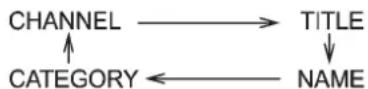
▼Rearseatentertainment
If your vehicle is equipped with a Rear Seat Entertainment System, you can enjoy audio outputs from the system through the vehicle's speakers by pressing the "RSEAUX" button(3). Press the
buttonagaintoreturntotheaudioset sound.
NOTE
If your vehicle is equipped with a Rear Seat Entertainment System, referto the Owner's Manual supplement for the Rear Seat Entertainment System for further details.
5-10Audio
■ Compactdiscplayeroperation
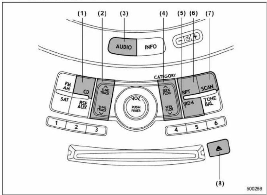
(1)CDbutton
(2)Trackbutton
(3)AUDIObutton
(4)SeekandFolderbutton
(5)Randombutton
(6)Repeatbutton
(7)Scanbutton
(8)Ejectbutton
▼Toplaybackacompactdisc
WhenCDisnotintheplayer
Holdadiscwithafingerinthecenterhole whilegrippingtheedgeofthedisc,then insertitintotheslot(withthelabelside up)andtheplayerwillautomaticallypull thediscintoposition.
NOTE
•DONOTINSERTTWODISCSINTO THEDISCINSERTIONSLOTATTHE SAMETIME.
- Besuretoinsertadiscwiththelabel sideup.Ifyouinsertthediscthelabel sidedown,"CHECKDISC"willappear onthedisplayandtheplayerwillnot playanything.
- Afterthelastsongfinishes, the playerwillautomaticallyreturntotrack 1 (thefirstsongonthedisc).
- Ifyouinsertadiscthatcannotbe playedbytheplayer, "CHECKDISC" willappearonthedisplayandthe playerwillreverttothepreviously selectedmode.
●Theplayerisdesignedtobeableto playmusicCD-RsandmusicCD-RWs, butitmaynotbeabletoplaycertain ones. - CDs(i.e.,8cm/3inchCDs)arenot supported, and if inserted, they will be immediately ejected.
WhenCDisintheplayer
Whenthe"CD"button(1)ispressed,the playerwillstart playback.
NOTE
Afterthelastsongfinishes, the player will automatically return to track 1 (the first song on the disc).
▼TostopplaybackofaCD
When the "PUSH POWER" button is pressed during playback of a CD, the CD stops playing temporarily. Tolet the CD resume playing, pres the button again.
▼Toselectasongfromitsbeginning
▽Forwarddirection
Brieflypressthe" ^ "sideofthe"TUNE TRACK"button(2)toskiptothebeginning
ofthenexttrack/file(track).Eachtimethis sideofthebuttonispressed,theindicated track/file(track)numberwillincrease.
NOTE
InanMP3folder, skippingpastthelast track/file(track) will take you back to the first track/file(track) in the folder.
Backwarddirection
Brieflypressthe" √”sideofthe“TUNE TRACK”button(2)toskiptothebeginning ofthecurrenttrack/file(track).Eachtime thissideofthebuttonispressed,the indicatedtrack/file(track)numberwill decrease.
NOTE
InanMP3folder, skipping past the last track/file(track) will take you back to the first track/file(track) in the folder.
▼Fast-forwardingandfast-reversing
∇Fast-forwarding
Pressthe“^”sideofthe“TUNETRACK”button(2)continuouslytofast-forwardthe track/file.
Releasethebutton to stopfast-forwarding.
NOTE
If you fast-forward past the last track/file(track) on the disc, the player will
selectthefirsttrack/file(track)onthe discandstartplayingit.
∇Fast-reversing
Pressthe" ∨ sideofthe"TUNETRACK" button(2)continuouslytofast-reversethe track/file(track).
Releasethebuttontostopfast-reversing.
NOTE
If you fast-reverseto the beginning of the first track / file (track) on the disc, the fast-reversing will stop and the player will start playing the first track / file (track) on the disc.
▼Folderselection(MP3disc)
Pressthe“^”sideofthe“SEEKFLDR”button(4)brieflytoselectthenextfolder. Pressingthe“∨”sideofthesamebutton thefirsttimemakesthestplayergobackto thebeginningofthecurrentlyselectedfile; pressingitasecondtimemakesitgoback tothepreviouslyselectedfile.
NOTE
OnlyMP3foldersarerecognizedwhen anattempttoselectthenextorpreviousfolderismade.Ifnoappropriate folderexistsonthedisc,pressingthe “^” or “∨” side of the “SEEK FLDR” buttonhasnoeffect.
-CONTINUED-
5-12Audio
▼Repeating
∇Torepeatthecurrentlyplayingtrack/file(track)
Torepeatatrack/file(track),brieflypress the"RPT"button(6)whilethetrack/file(track)isplaying.Thedisplaywillshow "RPT",andthetrack/file(track)willbe repeated.
Tocancelthetrack/file(track)repeat-play mode:
Pressthe"RPT"buttononce(non-MP3 disc)
Pressthe“RPT”buttontwice(MP3disc) The“RPT”indicationwillturnoff,andthe normalplaybackmodewillberesumed.
NOTE
- WithanMP3discinserted, each timeyoubrieflypressthebutton, the modewillchangetothenextoneinthe followingsequence.

If you accidentally press the button and cancel the track/file(track) repeat-play mode, press it againtoreselect the repeat-play mode.
- Therepeat-playmodewillbecan- celedifyouperformanyofthefollow- ingsteps.
-Pressthe"RDM"button
-Pressthe"SCAN"button
-Pressthe" ▲"button
-Selecttheradiomode
-Pressthe"RSEAUX"button
-Pressthe“ ∨”or“ ∧”sideofthe
"SEEKFLDR"button(MP3disc)
-Turnoffthepoweroftheaudio equipment
-Turntheignitionswitchtothe
"LOCK"position
∇ To repeat the currently playing folder (MP3disc)
Torepeat thecurrently playingfolder, pressthe "RPT" button(6)twicewhilea file(track) isplaying. Thedisplaywillshow "F-RPT", andthefolderwillbeplayed repeatedly.
Tocancelthefolderrepeat-playmode, pressthe“RPT”buttononcemore. The “F-RPT”indicationwillturnoff, and the normal playbackmodewillberesumed.
NOTE
- Each timeyoubriefly press the button, themodewillchangetothe nextoneinthefollowingsequence.
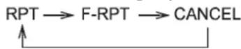
If youaccidentallypressthe buttonand
cancel thefolderrepeat-play mode, pressitagaintoreselectthefolder repeat-playmode.
- Thefolderrepeat-playmodewillbe cancelledifyouperformanyofthe followingsteps.
-Pressthe"RDM"button
-Pressthe"SCAN"button
-Pressthe" ▲"button
-Selecttheradiomode
-Pressthe"RSEAUX"button
-Pressthe“ ∨”or“ ∧”sideofthe
"SEEKFLDR"button(MP3disc)
-Turnoffthepoweroftheaudio equipment
-Turntheignitionswitchtothe
"LOCK"position
▼Random playback
Non-MP3disc
Pressthe“RDM”button(5)brieflyduring discplaybacktoplayallofthetrackson the disc in a random order. The display will show“RDM”, andallofthetrackson the discwillbeplayedinarandomorder.
Tocancelrandommode, pressthebutton again. The "RDM" indication will turn off, and then normal playback mode will be resumed.
NOTE
Random playback will be cancelled if you perform many of the following steps.
- Pressthe"RPT"button
- Pressthe"SCAN"button
-Pressthe" ▲"button - Selecttheradiomode
- Pressthe"RSEAUX"button
- Pressthe" ∨"or"'sideofthe "SEEKFLDR"button
•Turnoffthepoweroftheaudio equipment
●Turntheignitionswitchtothe "LOCK"position
MP3disc
Pressthe“RDM”button(5)duringdisc playbacktoplayallofthetracksinthe foldercurrentlybeingplayedinrandom order.Pressthe“RDM”buttonagainto playallofthetracksonthediscinrandom order.Thedisplaywillshow“RDM”during therandommode.
Tocanceltherandommode, press the "RDM" button during "in-disc" random playback. The "RDM" indication will turn off, and then normal playback modewill be resumed.
NOTE
- Eachtimeyoubrieflypressthe button, themodewillchangetothe
nextoneinthefollowingsequence.
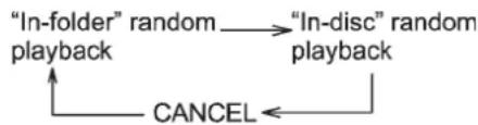
flowchart
graph TD
    A[""In-folder" random"] --> B[""In-disc" random"]
    B --> C["playback"]
    C --> D["CANCEL"]
    D --> A
If you accidentally press the button and cancel the random mode, press it again to reselect the random mode.
- Random playback will be cancelled if you perform many of the following steps.
-Pressthe"RPT"button
-Pressthe"SCAN"button
-Pressthe" ▲"button
-Selecttheradiomode
—Pressthe“RSEAUX”button
-Pressthe" ∨"or"'sideofthe "SEEKFLDR"button
-Turnoffthepoweroftheaudio equipment
-Turntheignitionswitchtothe "LOCK"position
▼Scan
The scan mode lets you listen to the first 10secondsofeachtrack/file(track)onthe disc/folderinsuccession.Pressthe "SCAN"button(7)tostartscanning through all tracks upward beginning with thetrack/file(track)followingthecurrently
selected one. After all tracks/files (tracks) onthedisc/folderhasbeenscanned, normal playbackmodeisrestored.
Tocancelascan, pressthebuttonagain.
NOTE
Thescanmodewillbecancelledify you performanyofthe following operations.
- Pressthe"RPT"button
- Pressthe"RDM"button
- Pressthe" ▲"button
- Pressthe" ∧ "or""sideofthe "TUNETRACK"button
- Pressthe" ^"or""sideofthe "SEEKFLDR"button(MP3disc)
- Selecttheradiomode
- Pressthe"RSEAUX"button
•Turnoffthepoweroftheaudio equipment - Turn the ignition switch to the "LOCK" position
▼Toeject adiscfromtheplayer
Whenadiscisbeingplayedbackorwhen adiscisintheplayer,pressthe" button(8).Thediscwillbeejected.

NOTE
- Avoid driving the vehicle with a CD stickingout, because vibration might make it fallout.
-CONTINUED-
5-14Audio
- If the disc is left rejected from approximately 15 seconds after the ignition switch is turned to the "LOCK" position, adis protection function will operate, automatically reloading the disc. In this case, the disc is not played.
▼Displayselection(MP3disc)
If you press the "AUDIO" button (3) during playback, the indication will change the next one in the following sequence.
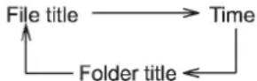
▼Page(track/foldertitle)scroll(MP3 disc)
If, havingpressedthe"AUDIO"button(3) toselecttracktitleorfoldertitledisplay, youpressthe"AUDIO"buttonagainfor lessthan0.5second, the titlewill be scrolledsoyoucanseeallofit. You will see eight characters at a time.
NOTE
Thedisplayisdesignedtoshowtitles foruptothreepages(64charactersin total).
TypeBaudioset(ifequipped)
The audio set will operate only when the ignition switch is in the "Acc" or "ON" positions.
Radiooperation
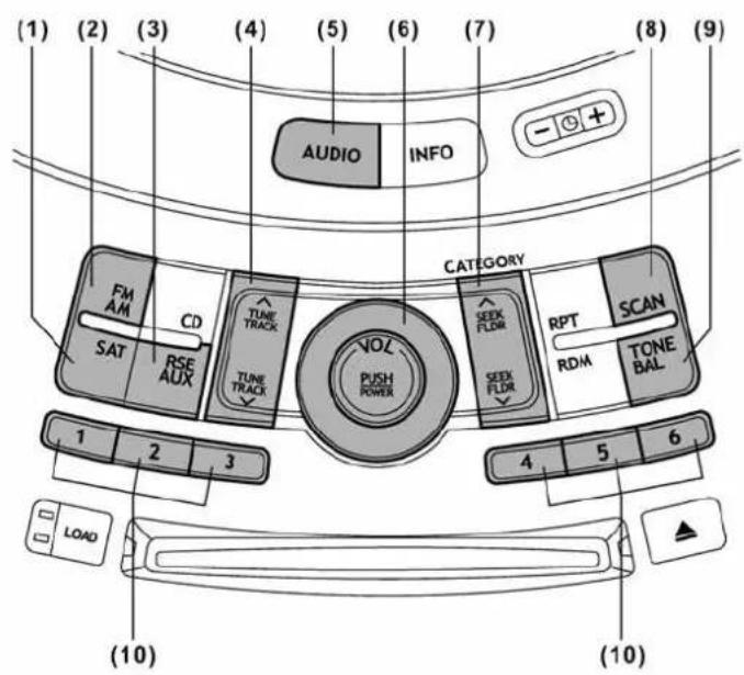
500265
(1)Satelliteradiomodebutton
(2)FMAMmodebutton
(3)AuxiliaryaudiunitandRearseat entertainmentselectionbutton
(4) Tuningbutton
(5)AUDIObutton
(6)Powerswitch,volumecontroldial
(7)Seekbutton
(8)Scanbutton
(9)ToneandBalancebutton
(10)Presetbutton
▼Powerswitchandvolumecontrol
Thedial(6)isusedforbothpower(ON/OFF)andvolumecontrol.Theradiois turnedONandOFFbypushingthedial andthevolumeiscontrolledbyturningthe dial. Thedialcanalsobeusedfortone andbalanceadjustment.
▼Toneandbalancecontrol
The volume controldial(6) normally functions as a volume control. This dial becomes a control for Bass, Midrange, Treble, Faderor Balance when you select the appropriate tone and balance control mode.
Choosedesiredvolumelevelforeach modebyturningthevolumecontroldial. Thecontrolfunctionreturnstovolume controlmodeafterapproximately5seconds.
-CONTINUED-
5-16Audio
▽Tochangetoneandbalancecontrol modes
Eachbriefpressofthe“TONEBAL” button(9)changescontrolmodesinthe followingsequencestartingfromvolume controlmode.(Whentheradioisfirst turnedon,thecontrolmodeisinthe volumecontrol.)
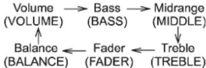
flowchart
graph TD
    A["Volume (VOLUME)"] --> B["Bass (BASS)"]
    B --> C["Midrange (MIDDLE)"]
    C --> D["Treble (TREBLE)"]
    D --> E["Fader (FADER)"]
    E --> F["Balance (BALANCE)"]
    F --> A
The "TONE BAL" button is used for selecting the following control modes.
| Controlmode(Rangeofle-vels) | 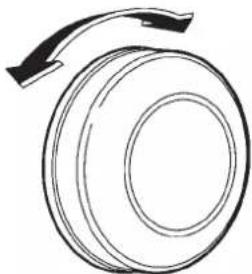 500204 500204 | |
| TurncounterclockwiseTurnclockwise | ||
| Basscontrol(-6to+6)ForlessbassoundFormorebasssound | ||
| Midrangecontrol(-6to+6)ForlessmidrangesoundFormoremidrangesound | ||
| Treblecontrol(-6to+6)ForlesstreblesoundFormoretreblesound | ||
| Fadercontrol(R9toF9) | Toincreaserearspeakervolumeanddecreasefrontspeakervolume | Toincreasefrontspeakervolumeanddecreaserearspeakervolume |
| Balancecontrol(L9toR9) | Toincreaseleftspeakervolumeanddecreaserightspeakervolume | Toincreaserightspeakervolumeanddecreaseleftspeakervolume |
| Volumecontrol(0to40)Forlessvolume | Formorevolume | |
| AUXvolumecontrol*(0to40) | Forlessvolume | Formorevolume |
*:OnlywhenanAUXaudioproductisconnected.
▼FM/AMradio
▽FM/AMselectionbutton
Push the "FM AM" button (2) when the radioisofftoturnontheradio.
Push the "FM AM" button when the radio isontoselectFM1, FM2orAMreception.
▽Stereoindicator
The stereo indicator "ST" will illuminate whenanFMstereobroadcastisreceived.
Manualtuning
Pressthe“ ^”sideofthe“TUNETRACK” button(4)toincreasethetuningfrequency andpressthetuningbuttonmarked“ √”to decreaseit.
Each time the button is pressed, the frequencyinterval can be changed between 10 kHz in the AM mode and 0.2 MHzintheFMmode.
If you hold down the “^” side of the button, the tuning frequency will increase continuously, and if you holldownthe “ ∨” side of the button, the tuning frequency will decrease continuously. Releasethe button when your desired frequency is reached.
-CONTINUED-
5-18Audio
NOTE
While you are holding downeitherside of the TUNE/TRACK button, the tuning frequency will not stop changing even if the frequency of are receivable station is reached.
▽Seektuning(SEEK)
Ifyoupressthe“ ^”or“”sideofthe “SEEKFLDR”button(7),theradiowill automaticallysearchforareceivable stationandstopatthefirstoneitfinds. Thisfunctionmaynotbeavailable,however,whenradiosignalsareweak.Insuch asituation,performmanualtuningto selectthedesiredstation.
Scantuning(SCAN)
Pressthe"SCAN"button(8)tochangethe radiototheSCANmode.Inthismode,the radioscansthroughtheradiobanduntila stationisfound.Theradiowillstopatthe stationfor5secondswhiledisplayingthe frequency,afterwhichscanningwillcontinueuntiltheentirebandhasbeen scannedfromthelowendtothehigh end.Pressthe"SCAN"buttonagainto canceltheSCANmodeand tostop onany displayedfrequency.
Pressthe" ^"or"sideofthe"SEEK FLDR"button(7)againtocancelthescan modeandtostoponanydisplayed
frequency.
Whenthe"SCAN"buttonispressedfor automatictuning, stationsarescanned in thedirectionoflowfrequenciestohigh frequenciesonly.
Automatic tuning may not function properly if the station reception is weakened by distance from the station or proximity to tall buildings and hills.
▼Selectingpresetstations
Presettingastationwithapresetbutton allowsyoutoselectthatstationinasing operation.UptosixAM,FM1andFM2 stationseachmaybepreset.
▼Howtopresetstations
- Pressthe"FMAM"button(2)toselect FM1,FM2orAMreception.
- Pressthe"SCAN"button(8)ortune theradiomanuallyuntilthedesiredstation frequencyisdisplayed.
- Pressoneofthepresetbuttonsfor morethan1.5secondstostorethe frequency.Ifthebuttonispressedforless than1.5seconds,theprecedingselection willremainmemory.
NOTE
- If the connection between theradio and battery is broken for any reason such as vehicle maintenance or radio
removal, allstations stored in the preset buttons are cleared. If this occurs, it is necessary to reset the preset buttons.
- Ifacellphoneisplacednearthe radio,itmaycausetheradiotoemit noisewhenitreceivescalls.Thisnoise doesnotindicatearadiomalfunction.
▼Satelliteradiomode(ifequipped)
Toreceivesatelliteradio,itisnecessaryto installtheSUBARUgenuinesatellite receiver(optionalpart)andtoenterinto a contract.For details,pleasecontactyour SUBARUdealer.
▽Siriusatelliteradio
Siriussatelliteradioisarecentinnovation thatallowsthetistenertoexperience digitalsoundqualityandtohaveagreater varietyofchannels. Useofsatelliteradio(Sirius)requiresa tuner,antennaandaservicecontract.For details,pleasecontactyourSUBARU dealerorvisitSiriusSatelliteRadioat www.sirius.comorcall1-888-539-SIRIUS (7474)formoreinformation.Sirius,the Siriusdoglogo,channelnamesandlogos aretrademarksofSIRIUSSatelliteRadio Inc.
XM^TM satelliteradio
XM™ isacontinentalU.S.basedsatellite radioservice,includingmusic,news, sports,talkandchildren'sprogramming. XM™ providesdigitalqualityaudioand textinformation,includingsongtitleand artistname.Aservicefeeisrequiredto receivetheXM™ service.Formore information,contactyourSUBARUdealer orXM™ at www.xmradio.com or call 1-800-XMRADIO(1-800-967-2346)forU.S. www.xmradio.caorcall1-877-GET-XMSR (1-877-438-9677)forCanada.
▽Satelliteradioreception
Satelliteradiosignalsarebestreceivedin areaswithaclearviewoftheopensky.In areaswheretherearetallbuildings,trees, tunnelsorotherstructuresthatmay obstructthesignalofthesatellites,there maybesignalinterruptions.Othercircum- stancesthatmayresultinsignalloss includedrivingnearawall,steepcliffor hill,ordrivingonthelowerlevelofamulti- tieredroadorinsideaparkinggarage.
To help reduce this condition, satellite radioproviders have installed ground-based repeaters in heavily populated areas. However, you may still experience reception problems in some areas.
▽ DisplayingsatelliteradiolDoftuner
When you activate satelliteradio, you should have yours atelliteradiotunerID ready because each tuner is identified by its uniques atelliteradiotunerID.
ThesatelliteradiolDwillbeneededwhen you activate satellite radio and receive satelliteradiocustomersupport.
ThesatelliteradiolDcanbefoundonthe audiodisplaybytuningthechannelto"0".
Turnthe"TUNE/TRACK"button(4)to selectthesatelliteradiochannel.
▽Bandselectionbutton
Pushthe"SAT"button(1)when theradio isofftoturnonthe radio.
Pushthe "SAT" buttonwhetheradiois on to select SAT1, SAT2 or SAT3 reception.
▽Channelselection
Press“ ^”ofthe“TUNETRACK”button (4)toselectthenextchannelandpress “√”ofthebuttontoselecttheprevious channel.
Keeppressing“ ^”ofthebuttonto changetothenextchannelcontinuously andkeepressing“ √”ofthebuttonto changetothepreviouschannelcontinuously.
Categoryselection
Press“^” or “∨” of the “SEEK FLDR” button (7) to display the current category. Press“^”againtoselectthenext category, and press“∨”againtoselect thepreviouscategory.
▽Channelscan
Press the "SCAN" button (8) to change the radiotothe SCANmode. Inthismode, the radioscansthroughthechannelsuntila stationisfound. Theradio willstopatthe stationfor 5secondswhile displayingthe channelnumber,afterwhichscanningwill continueuntiltheentirechannelhasbeen scannedfromthelowendtothehighend.
Also during the category selection, channels can be performed in that category.
Press the "SCAN" button again to cancel the SCANmode and to stop on any displayed channel.
▼Selectingpresetchannels
Presetting a channel with a preset button (10) allows youtoselect that channelina single operation. Uptosix, SAT1, SAT2 and SAT3 channel each may be preset.
▼Howtopresetchannels
- Pressthe "SAT" button(1) to select SAT1, SAT2 and SAT3 reception.
-CONTINUED-
5-20Audio
- Pressthe "SCAN" button(8) or the "TUNETRACK" button(4) to select the channel.
- Pressoneofthepresetbuttons(10) formorethan1.5secondstostorethe channel. If the button is pressed for less than 1.5 seconds, the preceding selection will remain in memory.
NOTE
If the connection between theradio and battery is broken for any reasons such as vehicle maintenance or radioremoval, all channels stored in the preset buttons are cleared. If this occurs, it is necessary to reset the preset buttons.
▽Displayselection
Pressthe"AUDIO"button(5)whilereceivingsatelliteradiotochangethedisplayas follows.
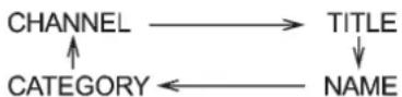
▼Rearseatentertainment
If your vehicle is equipped with a Rear Seat Entertainment System, you can enjoy audio outputs from the system through the vehicle's speakers by pressing the "RSEAUX" button (3). Press the
buttonagaintoreturntotheaudioset sound.
NOTE
If your vehicle is equipped with a Rear Seat Entertainment System, referto the Owner's Manual supplement for the Rear Seat Entertainment System for further details.
Audio5-21
BuiltinCDchangeroperation
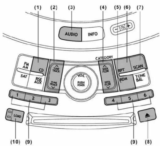
(1)CDbutton
(2)Trackbutton
(3)AUDIObutton
(4)SeekandFolderbutton
(5)Randombutton
(6)Repeatbutton
(7)Scanbutton
(8)Ejectbutton
(9)Discselectbutton
(10)Loadbutton
NOTE
- Besuretoinsertadiscwiththelabel sideup.Ifyouinsertthediscthelabel sidedown,"CHECKDISC"willappear onthedisplayandtheplayerwillnot playanything.
- Ifadiscisinsertedduringaradio broadcast,thediscwillinterruptthe broadcast.
●Theplayerisdesignedtobeableto playmusicCD-RsandmusicCD-RWs, butitmaynotbeabletoplaycertain ones. - CDs(i.e.,8cm/3inchCDs)arenot supported, and if inserted, they will be immediately ejected.
- Insertdiscsslowly,oneatatime. Insertingdiscsoneoveranothercould resultinmalfunctionoftheCDchanger.
-CONTINUED-
5-22Audio
▼HowtoinsertaCD(s)
InsertingaCD
- Brieflypressthe"LOAD"button(10).If themagazineintheplayerhasanidle positionwhereyoucaninsertadisc,the discnumberindicatorassociatedwiththe idlepositionwillblink.
Ifnoindicatorblinks, itmeansthatthereis noidlepositioninthemagazine. - Afterthediscnumberindicatorhas startedtoflash, insertthediscwhen "LOAD" flashesonthedisplay. Thedisc will then be automatically drawn in, and the player will begin to playback the first track of the disc.
- Toinsertmorediscsinsuccession, repeatSteps1and2. Themagazinewill beloadedwithdiscsintheascending orderofpositionnumber.
If you donot insert any discin 15 seconds after you have pressed the "LOAD" button, the player will begin to playback the first track of the last disc you have inserted. - Thediscindicatorsteadilylightsupifa discisalreadyinsertedinthecorrespondingpositionofthemagazine.
- While the player is in the loading mode, if you press "FM AM" button, the player will enterthestandbymode.Pressthe"CD" button(1)tostart playback.
Insertingadiscinadesiredposition
1.Brieflypressthe"LOAD"button(10).If themagazineintheplayerhasanidle positionwhereyoucaninsertadisc,the discnumberindicatorassociatedwiththe idlepositionwillblink.
The positionsinthemagazinethe indicatorofwhichsteadilylightsuparealready loadedwithdiscs.
-
Pressthediscselectbutton(9)atthe positionwhereyouwanttoinsertadisc.
-
Insertthediscwhen"LOAD"flashes onthedisplay. Thediscwillthenbe automaticallydrawnin, and the player will begintoplay the first track on the disc.
- Ifyouwishtoinsertanotherdisc, repeattheprocedurebeginningwithstep 1.
If you donot insert any discin 15 seconds after you have pressed the "LOAD" button, the player will begin to playback the first track of the last disc you have inserted.
- While the player is in the loading mode, if you press "FM AM" button, the player will enterstandbymode.Pressthe"CD" button(1)tostart playback.
▼Loadingallthemagazine(fulldisc loadingmode)
- If you continuetopressthe "LOAD"
button(10)formorethan1.5seconds,the playerwillproducebeepsoundandwill enterthefulldiscloadingmode.
2.A"discnumber"indicatorwillblink, and "ALLLOAD"willbeondisplayfora periodof15seconds.Ifadiscissuccessfullyloadedduringthisperiod,thedisc numberindicatorwillstopblinkingandwill steadilylight.
3. Whentheloadingofadisciscomplete, thenextdiscnumberindicatorwill blink. ThenrepeatStep2.
4. Whenthemagazineisfilledwithdiscs byrepeatingSteps2and3, theplayerwill startplaybackofthediscs, beginningwith theoneinsertedfirst.
If you fail to insert any disc during each 15 seconds interval, the full disc loading mod will be canceled, and the player will start playback of the disc inserted first.
▼HowtoplaybackaCDormakea pause
▼WhenthereisnoCDinserted:
ProperlyinsertaCD. Referto "Howto insertaCD(s)" 5-22.
WhenaCDisloaded, the player will start playback of the CD, beginning with the first track.
▼WhenthereareCDsloaded:
Pressadesiredoneofthediscselect buttons(9)thediscnumberindicatorof whichsteadilylightsup. Theplayerwill thenstartplaybackoftheselectedCD, beginningwiththefirsttrack.
Ifadiscthattheplayercannotreadhas beenloaded, "CHECKDISC" will appear on the display and the player will not play anything.
▼Toselectasongfromitsbeginning
▽Forwarddirection
Brieflypressthe“^”sideofthe“TUNE TRACK”button(2)toskiptothebeginning ofthenexttrack/file(track).Eachtimethe buttonispressed,theindicatedtrack/file(track)numberwillincrease.
NOTE
InanMP3folder, skippingpastthelast track/file(track) will take you back to the first track/file(track) in the folder.
Backwarddirection
Brieflypressthe“ √”sideofthe“TUNE TRACK”button(2)toskiptothebeginning ofthecurrenttrack/file(track).Eachtime thebuttonispressed,theindicatedtrack/file(track)numberwilldecrease.
NOTE
InanMP3folder, skipping past the first track/file(track) will take out the last track/file(track) in the folder.
▼Fast-forwardingandfast-reversing
∇Fast-forwarding
Pressthe“^”sideofthe“TUNETRACK”button(2)continuouslytofast-forwardthe track/file.
Releasethebuttontostopfast-forwarding.
NOTE
If you fast-forward to the end of the last track / file (track), fast-forwarding will stop and the player will start playback beginning with the first track / file (track).
∇Fast-reversing
Pressthe“ ∨”sideofthe“TUNETRACK” button(2)continuouslytofast-reversethe track/file.
Releasethebuttontostopfast-reversing.
NOTE
If you fast-reverseto the beginning of the first track/file(track), fast-reversing will stop and the player will start play-back.
▼Repeating
▽Torepeatthecurrentlyplayingtrack/file(track)
Torepeatatrack/file(track), briefly press the "RPT" button(6) while the track file (track) is playing. The display will show "RPT", and the track file (track) will be repeated.
Tocancelthetrack/file(track)repeat-play mode, briefly press the "RPT" button twice. The "RPT" indication will turn off, and the normal playback modewill be resumed.
NOTE
- Eachtimeyoubrieflypress the button, the mode will change to the nextoneinthefollowingsequence.

If you accidentally press the button and cancel the track/file(track) repeat-play mode, press it again to reselect the repeat-play mode.
- Therepeat-playmodewillbecan- celledifyouperformanyofthefollow- ingsteps.
-Pressthe"RDM"button
-Pressthe"SCAN"button
-Pressthe" ▲"button
-CONTINUED-
5-24Audio
-Pressthe"RSEAUX"button
-Pressthe" ∨"or""sideofthe
"SEEKFLDR"button(MP3disc)
-Turnoffthepoweroftheaudio equipment
-Turntheignitionswitchtothe
"LOCK"position
▽Torepeatthecurrentlyplayingdisc/folder
Torepeatthecurrentlyplayingdisc/folder, pressthe“RPT”button(6)twicewhila a track/file(track)isplaying. Thedisplaywill show“D-RPT”, andthedisc/folderwill be playedrepeatedly.
Tocancel thedisc/folder repeat-play mode, pressthe "RPT" buttononcemore. The "D-RPT" indicationwillturnoff, and thenormal playbackmodewill be resumed.
NOTE
• Each time you briefly press the button, themodewillchangetothe nextoneinthefollowingsequence.

If you accidentally press the button and cancel the disc/folder repeat-play
mode, pressitagaintoreselectthe disc/folderrepeat-playmode.
- The disc/folder repeat-play mode will be cancelled if you perform many of the following steps.
- Press the "RDM" button
- Press the "SCAN" button
- Pressthe" ▲"button
- Pressthediscselectbutton
- Selecttheradiomode
- Press the "RSE AUX" button
- Pressthe“ ∨”or“”sideofthe
"SEEKFLDR"button(MP3disc)
– Turnoffthepoweroftheaudio equipment
- Turn the ignition switch to the "LOCK" position
▼ Random playback
Non-MP3disc
Pressthe“RDM”button(5)brieflyduring discplaybacktoplayallofthetrackson the disc in a random order. The display will show“RDM”, andallofthetrackson the discwillbeplayedinarandomorder.
Tocancelrandommode, pressthebutton again. The "RDM" indication will turn off, and then normal playback modewill be resumed.
NOTE
Random playback will be cancelled if you perform many of the following steps.
- Press the "RPT" button
- Press the "SCAN" button
- Pressthe" ▲"button
- Selecttheradiomode
- Press the "RSE AUX" button
- Pressthe“ ∨”or“”sideofthe “SEEKFLDR”button
- Turn off the power of the audio equipment
- Turn the ignition switch to the "LOCK" position
MP3disc
Press the "RDM" button (5) during disc playbacktoplayallofthetracksinthe folder currentlybeing played inrandom order. Press the "RDM" button again to playallofthetracksonthediscinrandom order. Thedisplaywillshow "RDM" during therandommode.
To cancel the random mode, press the "RDM" button during "in-disc" random playback. The "RDM" indication will turn off, and then normal playback modewill be resumed.
NOTE
- Eachtimeyou brieflypressthe button, themodewillchangetothe
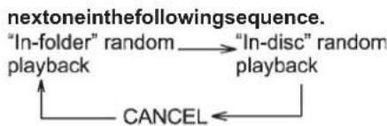
flowchart
graph TD
    A[""In-folder" random playback"] --> B[""In-disc" random playback"]
    B --> C["CANCEL"]
If you accidentally press the button and cancel the random mode, press it again to reselect the random mode. ●Random playback will be cancelled if you perform many of the following steps.
-Pressthe"RPT"button
-Pressthe"SCAN"button
-Pressthe" ▲"button
-Selecttheradiomode
-Pressthe"RSEAUX"button
-Pressthe" ∨"or"'sideofthe
"SEEKFLDR"button
-Turnoffthepoweroftheaudio equipment
-Turntheignitionswitchtothe
"LOCK"position
▼SCAN
Thescanmodeletyoulistentothefirst 10secondsofeachtrack/file(track)in succession.Pressthe"SCAN"button(7) tostartscanningupwardbeginningwith thetrack/file(track)followingthecurrently selectedone.Whenalltracks/files(tracks) inthedisc/folderhavebeenscanned,
normal playback will be resumed. To cancel the scan mode, press the button again.
NOTE
Thescanmodewillbecancelledify you performanyofthefollowingsteps.
- Pressthe"RPT"button
- Pressthe"RDM"button
- Pressthe" ∨"or""sjdeofthe "TUNETRACK"button
- Pressthe" √"or""sjdeofthe "SEEKFLDR"button(MP3disc)
-Pressthe" ▲"button
•Pressthediscselectbutton - Selecttheradiomode
- Pressthe"RSEAUX"button
•Turnoffthepoweroftheaudio equipment - Turntheignitionswitchto the "LOCK"position
▼Displayselection(MP3disc)
If you press the "AUDIO" button(3) during playback, the indication will change the next one in the following sequence.
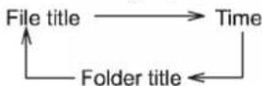
▼Page(track/foldertitle)scroll(MP3 disc)
If, havingpressedthe"AUDIO"button(3) toselecttracktitleorfoldertitledisplay, youpressthe"AUDIO"buttonagainfor lessthan0.5second, thetitlewill be scrolledsoyoucanseeallofit. You will see eight characters at a time.
NOTE
Thedisplayisdesignedtoshowtitles foruptothreepages(64charactersin total).
▼Folderselection(MP3disc)
Pressthe" ^" sideofthe" SEEKFLDR" button(4)brieflytoselectthenextfolder. Pressingthe" ∨" sideofthesamebutton thefirsttimemakestheplayergobackto thebeginningofthecurrentlyselectedfile; pressingitasecondtimemakesitgo back tothepreviouslyselectedfile.
NOTE
OnlyMP3foldersarerecognizedwhen anattempttoselectthenextorpreviousfolderismade.Ifnoappropriate folderexistsonthedisc,pressingthe "^" or "sjdeofthe"SEEKFLDR" buttonhasnoeffect.
5-26Audio
▼HowtounloadCDsfromtheplayer
▽EjectingaCDfromtheplayer
Ofthediscsloaded, you can select and remove only onedisc.
- Usethediscselectbutton(9)toselect thedisctobeejected.
2.Brieflypressthe" ▲"button(8).The selecteddiscwillbeejected. Thedisc numberindicatorwillflashatthistime. Whenyouremovetheejecteddisc, the discnumberindicatorwillturnoff.
Toremovemorediscsinsuccession, repeatSteps1and2.
▽Ejectingalldiscsfromtheplayer(all discejectionmode)
- If you continuetopressthe"
▲"button
(8), the player will produce beepsound and will enter the alldiscejection mode. - Removethediscthathasbeen ejected. The other discs loaded will then beejectedoneafteranother.Ifyoudonot remove the disc that has been ejected, the "Alldiscejectionmode"willbecanceled.
NOTE
- Avoid driving the vehicle with a CD stickingout, because vibration might make it fallout.
- Ifyoupressthe" ▲"buttonwhile
▲"buttonwhile
the player is in all disc ejection mode, themodewillbecancelledfollowing ejectionofthediscthatiscurrently beingejected.
- If you press the "CD" button while the player is in all disc ejection mode, the player will draw in the disc sthat have been ejected and play them.
Audiocontrolbuttons
Thesebuttonsare locatedonthe spokes ofthesteeringwheel. Theyallowthe drivertocontrolaudiofunctionswithout takinghis/herhandsoffthesteering wheel.
■MODE button
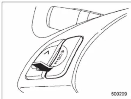
This button is used to select the desired audio mode. Each time it is pressed, the modechangestothenextoneinthe followingsequence.
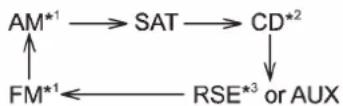
*1: The frequency last received in these selected
wavebandwillbedisplayed.
*2: OnlywhenaCDisintheplayer.
*3: Only vehicle equipped with RSE (Rear Seat Entertainment)
▼“”and“”buttons
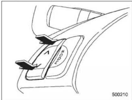
Withradiomodeselected
Pressthe“ ^”buttontoselectthenext channelandpressthe“ ∨”buttontoselect thepreviouschannel.
Thatstation's frequency will be shown on the audiodisplay.
WithCDmodeselected
Pressthe“ ^”buttontoskipforwardinthe track/file(track)order.Pressingthe“ ∨” buttonthefirsttimemakestheplayergo backtothebeginningofthecurrenttrack/
file(track);pressingitthesecondtime makesitgobacktotheprevioustrack/file (track).
Thetrack/file(track)numberwillbeshown ontheaudiodisplay.
▼Volumecontrolbuttons
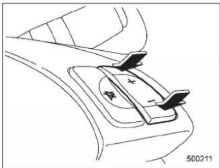
natural_image
Diagram of a car interior showing a steering wheel and directional arrows (no text or symbols)Pressthe“+”buttontoincrease the volume.Pressthe“-”buttontoreduce thevolume.
Anumberindicatingthevolumewillbe shownontheaudiodisplay.
▼MUTEbutton
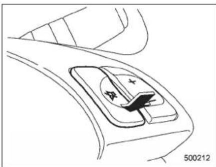
natural_image
Diagram of a car intake manifold with a directional indicator (no text or symbols)Pressthisbuttonifyouwishtoimmedi- atelycutthevolumetozero.
Theaudiodisplaywillshow"MUTE". Ifyoupressthebuttonagain,theoriginal soundvolumewillreturnand"MUTE" turnsoff.
NOTE
If your vehicle is equipped with a genuine SUBARU navigation system, the display will show " ☑".
Auxiliaryinputjack
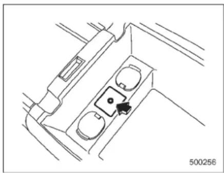
natural_image
Technical line drawing of a vehicle air vent or intake manifold with a black arrow pointing to the internal component (no text or symbols)Byconnectingacommercialaudioproducttothevehicle,suchasaportable audioplayer,youcanhearitssoundvia thevehicle'sspeaker.
Anauxiliary(AUX)inputjackisequipped inthelowercompartmentofthecenter console.Astereominipinplug(3.5ø)can beinsertedinthisjack.Theconnection cableisavailableatelectricalapplianceor similarstores.
TousetheAUXinputjack:
-
Connectaportableaudioplayertothe AUXinputjack.
-
Pressthe "RSEAUX" buttonon the audiocontrol panel to turn on the auxiliary audioinput.
-
Playback the portable audioplayer. Referto the Owner's Manual for the portable audioplayer.
NOTE
- The output sound of the portable audioplayerisnotloud, and the sound via the vehicle's speaker that are connected to the vehicle audioset may be very low. If you turn up the volume of the audioset, the volume becomes louder. However, when you changefrom one portable audioplayer to another one, the volume levels via the vehicle's speakers may be significantly louder compared to the prior device. To avoid a large volumed difference, turn down the volumewhen you change between portable audio players.
- In some cases, when the sound volume of the portable audio player is low, the sound becomes bad when you turn up the volume of the vehicle audio system. In this case, adjust the sound volume of the portable audioplayer.
•In somecases, noise occurs because ofabad connection between the portable player and the vehicle audio system. Trycleaning the stereo jack and audioplug. - Ifnoiseisnotreduced,checkfor
disconnectionofthecordormalfunc- tionsoftheportableplayer.
RearSeatEntertainment (RSE)systemoperation(if equipped)
If your vehicle is equipped with the Rear Seat Entertainment (RSE) system, you can list to the audio via the vehicle speakers. Push the "RSEAUX" button to play a DVD using the Rear Seat Entertainment system.
Fordetailedoperatingprocedures,referto theOwner'sManualsupplementforthe RearSeatEntertainment(RSE)system.
NOTE
- TowatchaDVDinthefrontseats usingthemonitorofthenavigation system, parkthevehicleinasafe locationandapplytheparkingbrake. ImagesoftheDVDwillnotbedisplayed onthefrontmonitorunlesstheparking brakeisapplied.
- Theharman/kardon® audiosystem isastereosystemwith2channels.lfa harman/kardon® audiosystem is equipped,theRearSeatEntertainment (RSE)systemmaynotgeneratea satisfyingrealisticsoundwhenplaying 5.1channelaudiosources.
Precautionstoobservewhen handlingacompactdisc
Useonlycompactdiscs(CDs, CD-Rsand CD-RWs) that havethemark shown in the following illustration. Also, some compact discscannotbeplayed.



500090
-CONTINUED-
5-30Audio
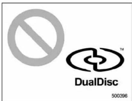
- YoucannotuseaDualDiscintheCD player.IfyouinsertaDualDiscintothe player,thediscmaynotcomeoutagain, possiblycausingtheplayertomalfunction.
●Incoldand/orrainyweather,dewcan forminsidetheCDplayer,preventing normaloperation.Ifthishappens,eject theCDandwaitfortheplayertodryout.
●SkippingmayoccurwhentheCD playerissubjectedtoseverevibration (for example, when the vehicle is driven onaroughsurface). - To remove a disc from the case, press the center of the case and hold both edges of the disc. If the disc surface is touched directly, contamination could cause poor tone quality. Do not touch the disc surface.
- Use a clean disc whenever possible. If
therearedeposits,wipethediscsurface fromthe centeroutwardwith adry,soft cloth.Besurenottouseahardcloth, thinner, benzine, alcohol, etc.
- Donotuseanydiscthatisscratched, deformed,orcracked.Also,donotuse any disc that has a non-standard shape (forexample,aheartshape).Malfunctions or problems might result.
●Adiscisvulnerabletoheat.Never keepiteitherinplacesexposedtodirect sunlight,nearheatersorinvehicles parked in the sun or on hot days.
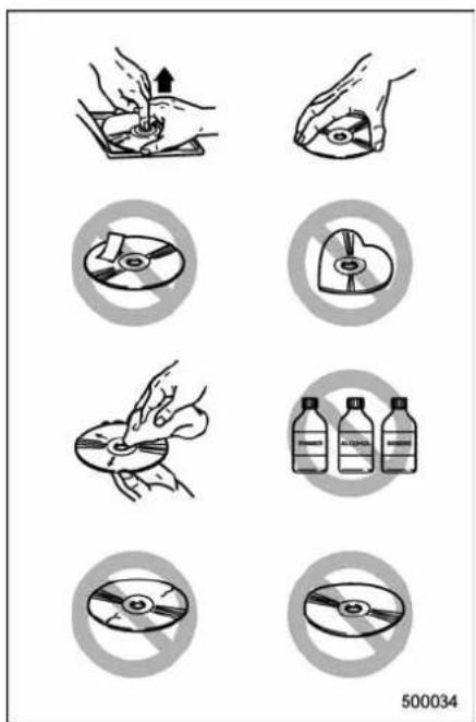
Interior equipment
Interiorlight....6-2
Domelight....6-2
Cargoarealight....6-3
Reargatelight....6-3
Maplight....6-3
Automaticambientlightforcenterconsolearea (ifequipped)....6-4
Sunvisors....6-4
Sunvisorextensionplate....6-5
Vanitymirrorwithlight....6-5
Storagecompartment......6-6
Glovebox....6-6
Centerconsolebox....6-6
Rearconsole....6-7
Overheadconsole....6-8
Cupholder....6-8
Front passenger's cup holder 6-8
Rearseat(5-seatermodels)/Second-rowseat (7-seater models) passenger's cup holder.... 6-9
Third-rowseatcupholders(7-seatermodels)......6-9
Bottleholders....6-9
Accessorypoweroutlets....6-10
Coat hook 6-12
Shoppingbaghook....6-13
Floor mat 6-13
Cargoareacover(ifequipped)......6-14
Using the cover 6-14
Toremovethecover....6-15
Toinstallthecoverhousing.... 6-15
Convenienttie-downhooks 6-16
Under-floorstoragecompartment......6-16
5-seater models 6-16
7-seater models 6-17
HomeLink®WirelessControlSystem
(if equipped) 6-17
Garagedooropenerprogramminginthe U.S.A. 6-18
Programmingrolling-code-protectedgaragedoor openersintheU.S.A. 6-19
Programmingforeentrancegatesand garagedoor openersinCanada.... 6-20
Programming other devices 6-21
OperatingtheHomeLink®WirelessControl System 6-21
Reprogramming a single HomeLink® button...... 6-21
Erasing HomeLink® button memory.... 6-21 Incaseaproblemoccurs.... 6-21
Rearviewcamera(ifequipped)......6-22
Howtousetherearviewcamera.... 6-23
Viewingrangeonthescreen.... 6-23
Help line.... 6-24
6-2 Interiorequipment
Interiorlight
Whenleavingyourvehicle,makesurethe lightisturnedofftoavoidbatterydischarge.
■Domelight
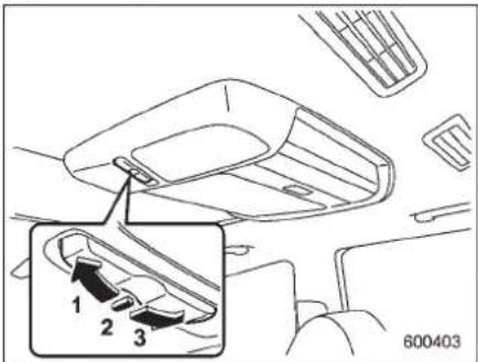
ModelswithRearSeatEntertainment
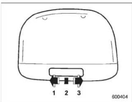
natural_image
Line drawing of a dome-shaped object with three labeled pins (1, 2, 3) at the base, no text or symbols on the object itself.ModelswithoutRearSeatEntertainment
1) ON
2)DOOR
3)OFF
Thedomelightswitchhasthefollowing threepositions.
ON: Thelightremainsoncontinuously.
OFF: Thelightremainsoff.
DOOR: Thedomelightilluminatesautomaticallyinthefollowingcases.
- Anyofthedoorsorthereargateis opened.
- Thedoorsorthereargateareunlockedusingtheremotekeylessentry transmitter.
●Theignitionswitchisturnedfromthe "Acc" position to the "LOCK" position.
The automatically illuminated domelight remains on for several seconds and then gradually turn so off after all doors and the reargate are closed. While the light is illuminated, if any of the following operations are performed, the domelight turns off immediately.
●Theignitionswitchisturnedfromthe "LOCK" position to "Acc" or "ON" position.
●Alldoorsandthereargatearelocked using the remote keyless entry transmitter.
The setting of the period for which the light remainson (OFFdelaytimer) can be changedbyaSUBARUdealer.Contact thenearestSUBARUdealerfordetails.
Cargoarealight
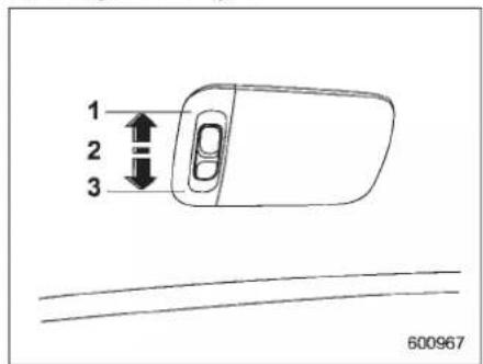
1) DOOR
2)OFF
3)ON
The cargo are alight switch has the following three positions.
DOOR: Thelightilluminateswhentherear gateisopened. Thelightremainsilluminatedforseveralsecendsandturnsoff afterthereargateisclosed.
OFF: Thelightremainsoff.
ON: Thelightremainsoncontinuously.
■Reargatelight
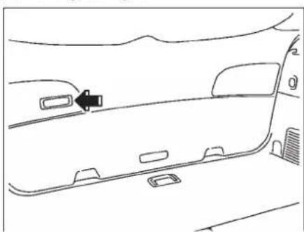
natural_image
Line drawing of a car interior with a vehicle and directional arrow (no text or symbols)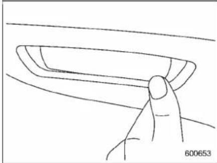
natural_image
Line drawing of a hand holding a small object, no text or symbols presentThereargatelightislocatedinsidethe vehicleonthereargate.Pushtheright sideoftheswitchtoturniton,andpush theleftsideoftheswitchtoturnitoff.
Maplight
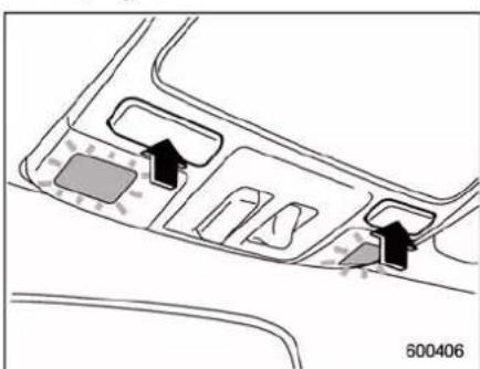
natural_image
Diagram of a vehicle interior layout with directional arrows indicating movement or flow (no text or symbols)Toturnonthemaplight, pushtheswitch. Toturnitoff, pushtheswitchagain.
Whenleavingthevehicle,makesurethe lightisturnedofftoavoidbatterydischarge.
Although themaplightswitchesareinthe OFFposition, themaplightsilluminate automatically in the following cases.
- Anyofthedoorsorthereargateis opened.
-Theoperational/non-operational settingofthisfunctioncanbechanged byaSUBARUdealer.Contactyour SUBARUdealertochangethesetting.
- The factory setting (default setting) forthisfunctionissetas "operational"
-CONTINUED-
6-4 Interiorequipment
(automaticillumination-ON).
- Thedoorsare unlocked using the remote key less sentry transmitter.
- Theignitionswitchisturnedfromthe "Acc" position to the "LOCK" position.
The automatically illuminated maplights remain illuminated for several seconds and then gradually turn off after all doors are closed.
While the lights are illuminated, if any of the following operations are performed, themaplightsturnoffimmediately.
- Theignitionswitchisturnedfromthe "LOCK" position to the "Acc" or "ON" position.
●Alldoorsandthereargatearelocked usingtheremotekeylessentrytransmitter.
Thesettingoftheperiodforwhichthelight remainsilluminated(OFFdelaytimer)can bechangedbyaSUBARUdealer.ContactyourSUBARUdealerfordetails.
NOTE
Ifanyofthedoorsorthereargateis notcompletelyclosed, themaplights willremainilluminatedasaresult. However, themaplightsareautomatically turnedoff by the battery drainage prevention function to prevent the battery from discharging. For details,
referto "Batterydrainageprevention function" 2-6.
■ Automaticambientlightfor centerconsolearea(if equipped)
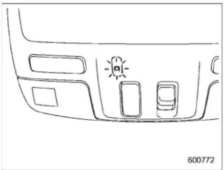
natural_image
Line drawing of a car's front and rear dashboard with no text or symbolsThe automatic ambient light illuminates when the ignition switch is in the "ON" position and the light control switch in the "ooe" position or "position. The light dimly illuminate the area around the center console. Thelight turn soff when the light control switch in the "OFF" position. Also, the brightness of the light is adjusted by the illumination brightness controldial.
Sunvisors
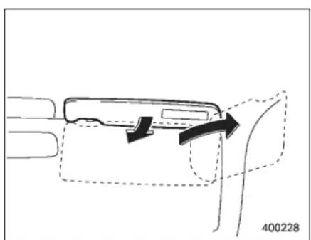
natural_image
Diagram of a mechanical component with arrows indicating motion, no readable text or symbols presentToblockoutglare, swingdownthevisors.
Tousethesunvisoratasidewindow, swingitdownandmoveitsideways.
Sunvisorextensionplate
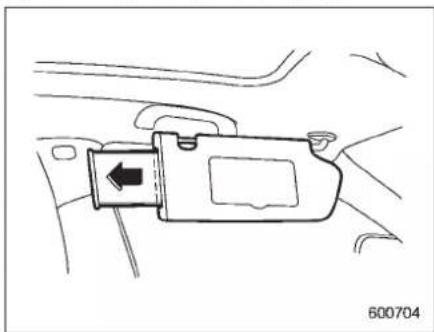
natural_image
Line drawing of a car seatbelt connector with an arrow indicating left side (no text or symbols)With the sunvisor positioned over the side window, you can use the sunvisor extension platetop prevent glare through the gap between the sunvisor and center pillar. Tou set the extension plate, pull it toward therearofthe vehicle. When you have finished using it, stowitbypushing it toward the front of the vehicle.
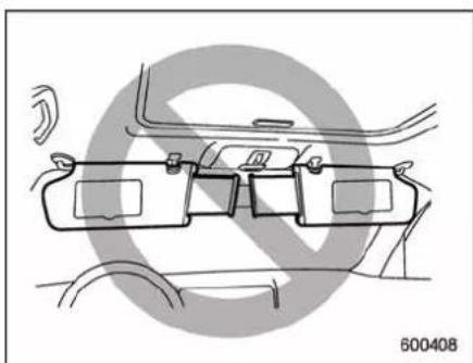
natural_image
Technical line drawing of a car frontview assembly (no text or symbols)
CAUTION
Donotpullouttheextensionplate withthesunvisorpositionedover thewindshield.Theextensionplate wouldobstructyourviewofthe rearviewmirror.
■Vanitymirrorwithlight

CAUTION
Keepthevanitymirrorcoverclosed whilethecarisbeingdriventoavoid beingtemporarilyblindedbythe glareofbrightlight.
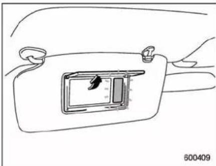
natural_image
Line drawing of a car interior showing the dashboard and steering wheel (no text or symbols)Tousethevanitymirror, swingdownthe sunvisorandopenthevanitymirrorcover. Thelightbesidethevanitymirrorilluminateswhenthemirrorcoverisopened.
NOTE
Useofthevanitymirrorlightforalong periodoftimewhiletheengineisnot runningcancausebatterydischarge.
6-6 Interiorequipment
Storagecompartment

CAUTION
●Alwayskeepthestoragecompartmentclosedwhiledrivingto reducetheriskofinjuryinthe eventofsuddenstopsoran accident.
- Donotstorespraycans, containerswithflammableorcorrosive liquidsoranyotherdangerous itemsinthestoragecompartment.
Glovebox
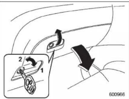
1)Lock
2)Unlock
Toopentheglovebox,pullthehandle.To closeit,pushthelidfirmlyupward. Tolocktheglovebox,insertthekeyand turnitclockwise.Tounlocktheglovebox, insertthekeyandturnitcounterclockwise.
■ Centerconsolebox
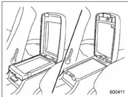
natural_image
Technical line drawing of a seatbelt device with two compartments and a diagonal line indicating alignment (no text or symbols)Thecenterconsoleboxhasatwo-layer structureconsistingofanuppercompartmentandalowercompartment.
▼Uppercompartment
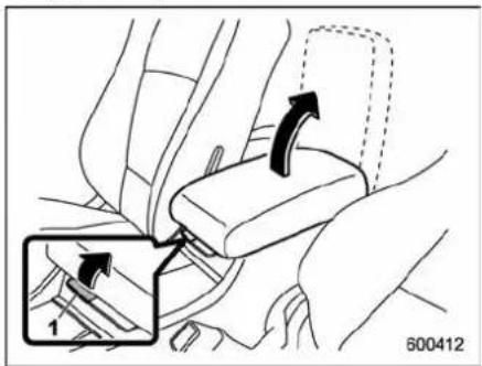
1) Uppercompartmentlockrelease
Pulluptheuppercompartmentlock
releasetoopentheuppercompartment.
▼Lowercompartment
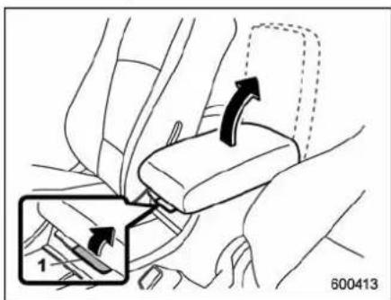
1) Lowercompartmentlockrelease
Pullupthelowercompartmentlock
releasetoopenthelowercompartment.
Rearconsole
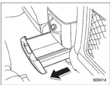
natural_image
Line drawing of a car seatbelt mechanism with a black arrow indicating the direction (no text or symbols present)Therearconsoleislocatedinthebackof thecenterconsolebox.Pullitouttouseit.
Overheadconsole
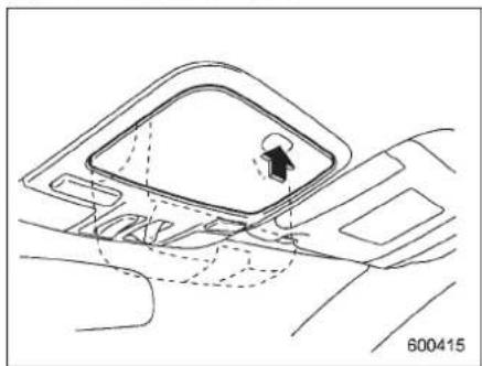
natural_image
Technical line drawing of a mechanical component with no visible text or symbolsToopentheconsole, pushonthelidlightly anditwillautomaticallyopen.

CAUTION
When your vehicle is parked in the sunoronawarmday, the inside of the overhead console heats up. Avoid storing plastic or other heat-vulnerable or flammable articles such as lighter in the overhead console.
Cupholder

CAUTION
Takecaretoavoidspills.Beverages, ifhot,mightburnyouoryour passengers.Spilledbeveragesmay alsodamageupholsteryorcarpets.
■Frontpassenger'scupholder

CAUTION
Donotpickupacupfromthecup holderorputacupintheholder whileyouaredriving,asthismay distractyouandleadtoanaccident.
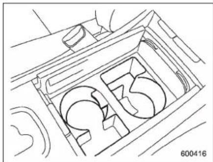
natural_image
Line drawing of a mechanical component with no visible text or symbolsThedualcupholderisbuiltintothecenter consoleneartheselectlever.
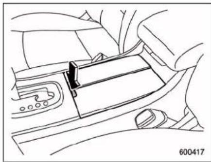
natural_image
Line drawing of a car seatbelt mechanism (no text or symbols)Toaccesssthecupholder, pushthe releasebutton.
■Rearseat(5-seatermodels)/Second-rowseat(7-seater models)passenger'scup holder
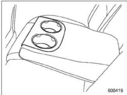
natural_image
Line drawing of a car interior compartment with two circular cutouts (no text or symbols)A dualcupholderisbuiltinthearmrest.

CAUTION
Whenacupcontainingabeverage isinthecupholder,donotslideor reclineanyseat. Otherwise,the beveragecouldspillwhiledriving and,ifthebeverageishot,itcould scaldyou.
■ Third-rowseatcupholders (7-seatermodels)
natural_image
Technical line drawing of a car interior corner with a handle and a small inset component (no text or symbols)Acupholderislocatedateachsideofthe third-rowseat.

CAUTION
Whenplacingabeverageinacup holder,makesureitiscapped. Otherwise,thebeveragecouldspill whiledrivingand,ifthebeverageis hot,itcouldscaldyou.
Bottleholders

CAUTION
- Donotpickupabottlefromthe bottleholderorputabottleinthe holderwhileyouaredriving,as thismaydistractyouandleadto anaccident.
- Whenplacingabeverageina doorpocket,makesureitis capped. Otherwise,thebeverage couldspillwhenopening/closing thedoororwhiledrivingand,if thebeverageishot,itcouldscald you.
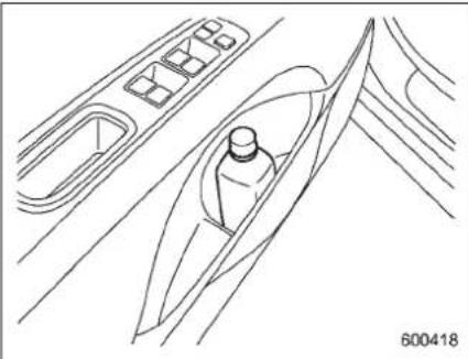
natural_image
Line drawing of a boat interior with control panel and vehicle (no text or symbols)Thedoorpocketequippedoneachdoor
-CONTINUED-
6-10 Interiorequipment
trimcanbeusedtoholdbeveragebottles andotheritems.
Accessorypoweroutlets
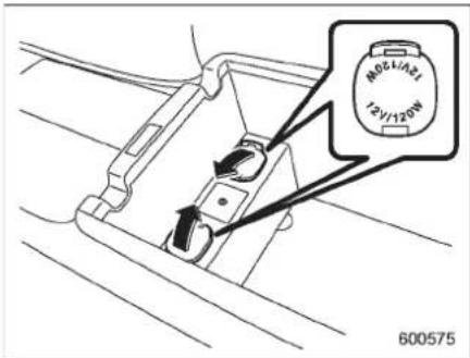
Poweroutletsinthecenterconsole
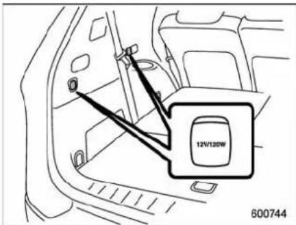
Poweroutletsintherearcabin
Accessorypoweroutletsareprovidedin thecenterconsole(lowercompartment) andintherearcabin.
Electricalpower(12VDC)fromthebattery isavailableatanyoftheoutletshwhenthe ignition switch is in either the "Acc" or "ON" position.
Youcanuseanin-vehicleelectrical appliancebyconnectingittoanoutlet. Themaximumpowerratingofanappliancethatcanbeconnecteddisshownin thefollowinglist.Donotuseanappliance whichexceedstheindicatedwattagefor eachoutlet.
- Thetwooutletsinthecenterconsole: 120Worless(Whenusingappliances connectedtotwooutletssimultaneously, thetotalpowerconsumedbythemmust notexceed120W.)
- Thetwooutletsintherearcabin:120W or less (When using appliances connectedtotwooutletssimultaneously,the totalpowerconsumedbythemmustnot exceed120W.)

CAUTION
- Donotattempttouseacigarette lighterinthe accessorypower outlets.
- Donotplaceanyforeignobjects,
especially metalonessuchas coinsoraluminumfoil, into the accessory power outlet. That could cause short circuit. Always put the capacitor the accessory power outlet when it is not in use.
- Useonlyelectricalappliances whicharedesignedfor12VDC.
Themaximumpowerratingofan appliancethatcanbeconnected isshowninthefollowinglist.Do notuseanappliancewhichexceedstheindicatedwattagefor eachoutlet.
-Thetwooutletsinthecenter console:120Worless(When usingappliancesconnected totwooutletssimultaneously, thetotalpowerconsumedby themmustnotexceed120W.)
-Thetwooutletsintherear cabin:120Worless(When usingappliancesconnected totwooutletssimultaneously, thetotalpowerconsumedby themmustnotexceed120W.)
Overloading the accessory poweroutletcancauseashort circuit.Donotusedualadapters ormorethanoneelectricalappli-
ance.
- Iftheplugonyourelectricapplianceiseithertoolooseortoo tightfortheaccessorypower outlet, thiscanresultinapoor contactorcausetheplugtoget stuck. Onlyuseplugsthatfit properly.
- Useofanelectricapplianceinthe accessorypoweroutletforalong periodoftimewhiletheengineis notrunningcancausebattery discharge.
●Beforedrivingyourvehicle,make surethattheplugandthecord onyourelectricalappliancewill not interfere with your shifting gears and operatingthe acceleratorandbrakepedals.Ifthey do,donotusethelectrical appliancewhiledriving.
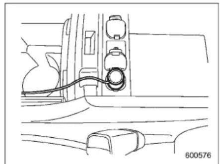
natural_image
Line drawing of a car interior showing a cable inserted into the airway (no text or symbols)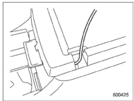
natural_image
Technical line drawing of a mechanical assembly with no visible text or symbolsNOTE
Itispossible,whenusingtheoutletin thecenterconsole(lowercompartment)withthelidclosed,topassthe electrical appliance's cord through a gapbetweenthecenterconsole(lower
-CONTINUED-
6-12 Interiorequipment
compartment)andthelid.Itisalso possibletopassthecordthrougha grooveinthelidanduptothecenter console(uppercompartment).
Coathook
Acoathookisattachedtoeachofthe passengerhandgripsfortheseatlistedin thefollowing.
-5-seatermodels:Rearseat
●7-seatermodels:Secondseat
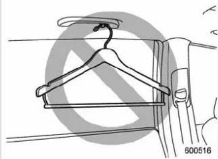
natural_image
Line drawing of a hanger on a wall, showing hanger and jacket (no text or symbols)
WARNING
Donothangcoathangersorother hardorpointedobjectsonthecoat hooks. If such items were hanging on the coathooks during deployment of the SR Scurtainairbags, they could cause serious injuries by coming off the coathooks and being thrown through the cabin or by preventing correct air bag deploy-
ment.Beforehangingclothingon thecoathooks,makesurethereare nopointedobjectsinthepockets. Hangclothingdirectlyonthecoat hookswithoutusinghangers.

CAUTION
Neverhanganythingonthecoat hookthatmightobstructthedriver's vieworthatcouldcauseinjuryin suddenstopsorinacollision.And donothangitemsonthecoathook thatweigh11lbs(5kg)ormore.
natural_image
Line drawing of a curved mechanical component with a circular end, resting on a surface (no text or symbols)Shoppingbaghook

CAUTION
Donothangitemsontheshopping baghookthatweigh11lbs(5kg)or more.
natural_image
Simple line drawing of a vehicle's side profile with no text or symbolsAshoppingbaghookisattachedtoeach sideofthecargoarea.
Floormat
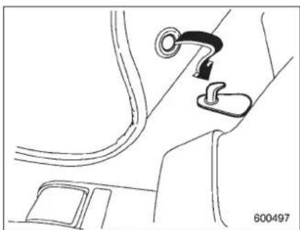
natural_image
Line drawing of a car interior showing a belt buckle and seatbelt mechanism (no text or symbols)Aretainingpinislocatedonthedriver's sideofthevehiclenexttothefuelfiller doorrelease.Fitthegrommetinthecarpet ontothepintopreventthecarpetfrom moving.
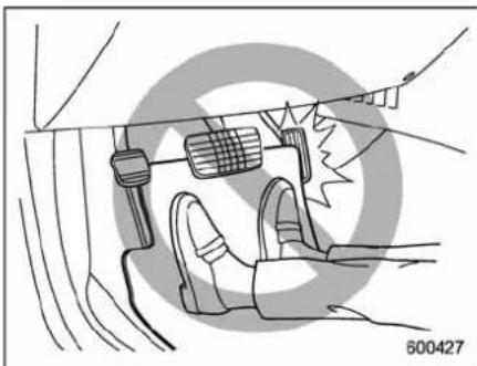
natural_image
Diagram of a car interior showing hand positioning and safety equipment (no text or symbols)
CAUTION
Makesurethedriver'sfloormatis placedbackinitsproperlocation andcorrectlysecuredonitsretainingpin. Also, donotusemorethan onefloormat. If the floormatslips forward and interferes with the movement of the pedals during driving, it could cause an accident.
6-14 Interiorequipment
Cargoareacover(if equipped)
The cargo area cover is provided for covering the cargo area and top protect its contents from direct sunlight. This covers detachable to maker room for additional cargo.
Usingthecover
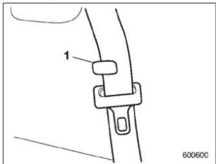
1) Holder
Inserttheseatbeltwebbingtotheholderof thethird-rowseat.(7-seatermodels)
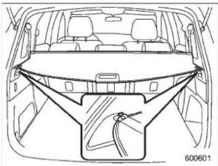
natural_image
Line drawing of a car rear view showing dashboard and seat structure (no text or symbols)Toextendthecover, pulltheendofthe coveroutofthehousing, theninsertits hooksintothecatchesasshown. To rewind it, unhook it from the catches and it will rewind automatically. You should holdontothecoverandguideitbackinto thecoverhousingwhileitisrewinding.
WARNING
Donotplaceanythingonthe extendedcover.Puttingexcessive weightontheextendedcovercan break it and an object on the cover couldtumbleforwardintheeventof asudden stop orcollision. This couldcauseseriousinjury.
CAUTION
- Becarefulnottopinchyourhand between the headrest and the cargoareacoverwhenyoure-clinetherearseat.
- Becarefulnottoscratchtherear gatestayswhileextendingand rewindingthecover. Scratchesonthestayscould causeleakageofgasfrom the stays,whichmayresultintheir inability to hold the rear gate open.
NOTE
When the headrestraintisadjusted at therearmostpositionoftheseatwith the seatback leaned back, the head restraintcomesincontact with the cargoareacover.In thiscase,raise theseatbackbeforeadjustingthehead restraint.
If the head restraint is correctly fixed in any of the lock positions, the head restraint does not contact the cargo area cover even when these at back is reclined.
Toremovethecover
- Rewindthecover.
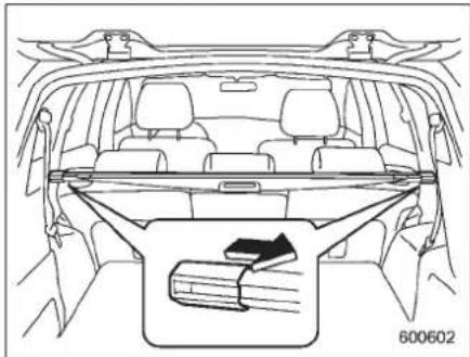
natural_image
Line drawing of a car interior showing rear seats, trunk, and seatbelt with a directional arrow indicating movement (no text or symbols)-
Pulleithersleeveontheendofthe coverhousingtoshortenthecover's length.
-
Takeitofftheretainer.
■Toinstallthecoverhousing
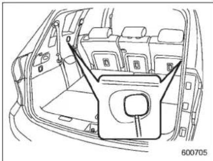
natural_image
Line drawing of a car interior showing the rear compartment with seat compartments and a central door (no text or symbols)-
Removethecoveratthecoverhousingretainingpartusingaflat-headscrewdriver.
-
Pulleithersleeveontheendofthe coverhousingtoshortenthecover's length.
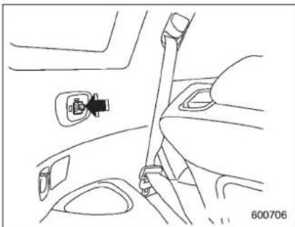
natural_image
Line drawing of a car interior showing a seatbelt and lock mechanism (no text or symbols)- Insert the projections located on the bothendsofthesleeveintotherecesses oftheretainers.
Convenienttie-downhooks

CAUTION
The convenient tie-downhooks are designed only for securing light cargo. Never try to secure cargo that exceed the capacity of the hooks. The maximum load capacity is 44 lbs (20 kg) per hook.
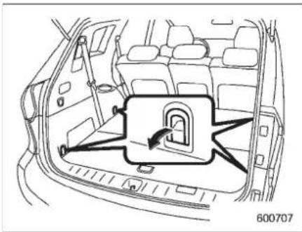
natural_image
Diagram of a car interior showing the door and seat area with a lock mechanism (no text or symbols)The cargo area is equipped with four tie-downhooks so that cargocan besecured with aluggagenetorropes.
When using the tie-downhooks, turn them down out of the storing recesses. When not in use, put the hooks up into the storing recesses.
Under-floorstoragecompartment
The subfloor storage compartment is located under the floor of the cargo area and can be used to store small items. To openthelid, pull the handle up.

CAUTION
•Alwayskeepthelidofthesub-floor storage compartment closedwhiledrivingtoreduce theriskofinjuryintheeventof suddenstoporanaccident.
- Donotstorespraycans, containerswithflammableorcorrosive liquidsorany otherdangerous itemsinthesubfloorstorage compartment.

5-seatermodels
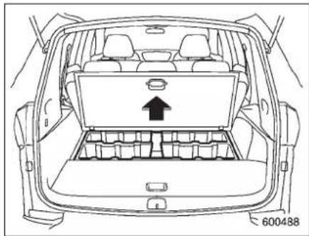
natural_image
Top-down line drawing of a car backrest with internal compartments and a central display panel (no text or symbols)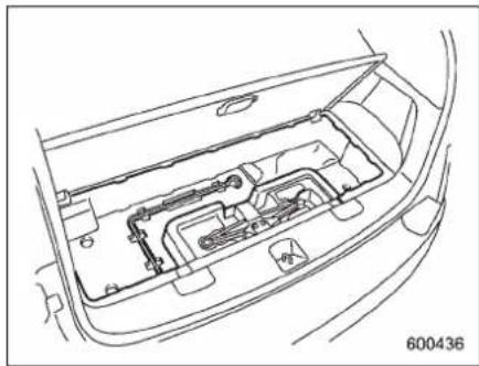
natural_image
Technical line drawing of a car interior showing internal components (no text or symbols)Hangthehookprovidedontheunderside oftherearhalflidontherearedgeofthe rooftokeepthelidopen.
7-seatermodels
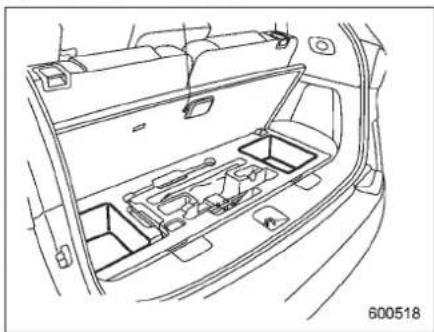
natural_image
Line drawing of a car interior showing the dashboard and rear seats (no text or symbols)Hangthehookprovidedontheunderside ofthelidontherearedgeoftheroofto keepthelidopen.
HomeLink®WirelessControl System(ifequipped)
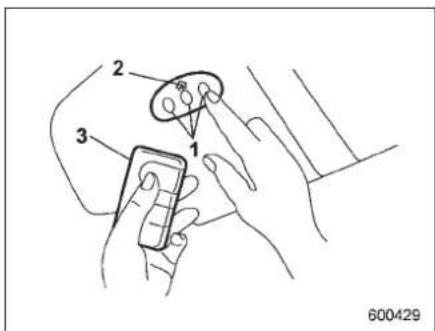
1) HomeLink® buttons
2) Indicatorlight
3) Hand-held transmitter*
* Not part of your vehicle's remote key less entry system but of a home link®-compatible device.
TheHomeLink®WirelessControlSystem, locatedonthedriver'ssunvisor,isahandywaytooperate,frominsideofyour vehicle,uptothreeremote-controlled indoorandoutdoordevices,suchas garagedooropeners,entrancegates, doorlocks,homelighting,andsecurity systems.TherearethreeHomeLink® buttonsonthesunvisor,eachofwhich youcanprogramforoperationofone
desireddevice.Fordetailsonthedevice typeswhichcanbeoperatedbythis system,consulttheHomeLinkwebsiteat www.homelink.comorcall1-800-355-3515.
Notethefollowingaboutthissystem: Ifyourvehicleisequippedwiththe HomeLink®WirelessControlSystem,it complieswithPart15oftheFederal CommunicationCommissionRulesinthe U.S.andtheRSS-210ofIndustryCanada inCanada.Itsoperationissubjecttothe followingtwoconditions:
(1) this device may not cause harmful interference, and (2) this device must accept any interferencereceived, including interference that may cause undesired operation.
Changesandmodificationstothissystem byanyoneotherthananauthorized servicefacilitycouldvoidauthorizationto usethisequipment.
HomeLinkandtheHomeLinkhouseare registeredtrademarksofJohnsonControls,Inc.

WARNING
- When programming the HomeLink® WirelessControl System,youmaybeoperatinga
-CONTINUED-
6-18 Interiorequipment
garagedooropenerorother device. Makesurethatpeople andobjectsareoutoftheway ofthegaragedooropeneror otherdevicetopreventpotential harmordamage.
- DonotusetheHomeLink®WirelessControlSystemwithany garagedooropenerthatlacks thesafetystopandreversefeaturesrequiredbyapplicable safetystandards.Agaragedoor openerwhichcannotdetectan object,signalingthedoortostop andreverse,doesnotmeetthese safetystandards.Usingagarage dooropenerwithoutthesefeaturesincreasesriskofserious injuryordeath.Formoreinformation,consulttheHomeLink websiteatwww.homelink.com orcall1-800-355-3515.

CAUTION
WhenprogrammingtheHomeLink® WirelessControlSystemtooperate agaragedooropeneroranentrance gate,unplugthedevice'smotor fromtheoutletduringprogramming topreventmotorburnout.
NOTE
- AfterprogrammingyourHomeLink® WirelessControlSystemforthede-sireddevices, retainthehand-held transmittersforfurtherprogramming ordevicetestingintheeventofa problem. - Itisrecommendedthatyouinserta newbatteryinthehand-heldtransmitterofadevicetoensurecorrect programming.
GaragedooropenerprogrammingintheU.S.A.
NOTE
WhenprogrammingtheHomeLink® WirelessControlSystemforagarage dooropener, ittissuggested that you park the vehicle outsidethegarage.
- Unplugthemotorofthegaragedoor openerfromtheoutlet.
NOTE
IfanyoftheHomeLink®buttonsare alreadyprogrammedforotherdevices, skipstep2becauseitclearsthe memoryofallthethreebuttons.
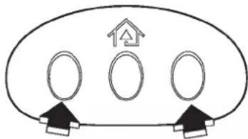
flowchart
graph TD
    A[" "] --> B[" "]
    C[" "] --> D[" "]
    E[" "] --> F[" "]
600430
- Pressandhold the two outside HomeLink® buttons until the indicator light beginstoflash(after20 seconds). Release both buttons.
- Hold the end of the agar aged door opener's hand-held transmitter between 1 and 3 inches (25 and 76 mm) away from the Home Link® button on the driver's sunvisor, keeping the indicator light in view.
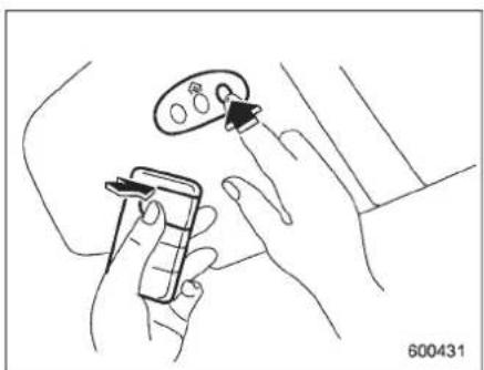
natural_image
Line drawing of hands holding a device and a small object, no text or symbols present- Using both hands, simultaneously push the hand-held transmitter button and the desired HomeLink® button. DO NOT releasethe buttons until step 5 has been completed.
- Holddownbothbuttonsuntilthe HomeLink®indicatorlightflashes,first slowlythenrapidly.Whentheindicator lightflashesrapidly,bothbuttonsmaybe released.(Therapidlyflashinglightindicateassuccessfulprogrammingofthenew frequencysignal.)
- PressandholdtheprogrammedbuttonandchecktheHomeLink®indicatorlight.Iftheindicatorlightstaysoncontinuously,yourgaragedoorshouldactivateandtheprogrammingiscompleted.Iftheindicatorlightflashesrapidlyfor2secondsandthenstaysoncontinuously,
yourgaragedooropenermaybeprotectedbyarollingcodefeature.Inthis caseyouneedtoperformadditionalsteps. Referto"Programmingrolling-code-protectedgaragedooropenersintheU.S.A." 6-19.
NOTE
Rolling-code-protectedgaragedoor openersaremanufacturedafter1996. Seetheinstructionmanualofyour garageopenerforconfirmation.
- Reconnectthemotorofyourgarage dooropenertotheoutlet.
- Testyourgaragedooropenerby pressingtheprogrammedHomeLink® button.
■ Programming rolling-code-protectedgarage door open-ersin the U.S.A.
If yourgaragedooropener hasarolling codefeature,programtheHomeLink® WirelessControlSystemforitbyfollowing steps1through5in"Garagedooropener programming in the U.S.A." 6-18 above. Thencontinuewiththefollowingsteps.
NOTE
The assistance of a second person may make the programming quicker
andeasier.
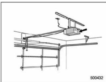
natural_image
Technical line drawing of a mechanical assembly with no visible text or symbols- Locatethetrainingbuttononthe garagedooropenermotorheadunit. Theexactlocationandcolor ofthebutton may vary by brand of garage door opener. Ifitisdifficulttolocatethe trainingbutton, refer to your garage door opener's instructionmanual.
6-20 Interiorequipment
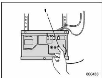
1) Trainingbutton
- Pressthetrainingbuttononthe garagedooropenermotorheadunit (whichactivatesthe"traininglight"onthe unit). Proceedtostep3within30seconds.
- Insidethevehicle, firmly press and releasetheHomeLink® button that was programmed in these section above. Press and releasethebuttonasecondtimeto complet the programming procedure.
NOTE
Somegaragedooropenersmayrequireyoutodotheaboveprocedurea thirdtimetocompletetheprogramming.
4. Thegaragedooropenershouldnow recognizetheHomeLink®WirelessCon-
trolSystemandyourgaragedooropener shouldactivatewhentheHomeLink® buttonispressed.
■ Programmingforentrance gatesandgaragedooropen-ersinCanada
- Unplugthemotoroftheentrancegate orgaragedooropenerfromtheoutlet.
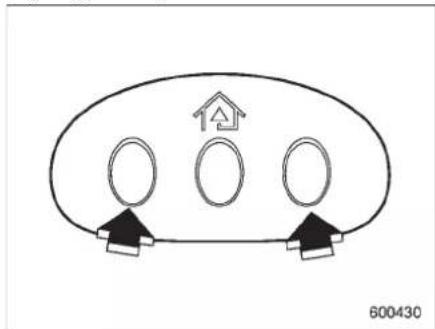
flowchart
graph TD
    A[" "] --> B[" "]
    C[" "] --> D[" "]
    E[" "] --> F[" "]
    G[" "] --> H[" "]
- Pressandholdthetwo outside buttons until the HomeLink® indicator light begins to flash (after 20 seconds). Release both buttons.
NOTE
IfanyoftheHomeLink®buttonsare alreadyprogrammedforotherdevices, skipstep2becauseitclearsthe
memoryofallthreebuttons.
3.Holdtheendoftheentrancegate's/garagedooropener'shand-heldtransmitterbetween1and3inches(25and76mm)awayfromtheHomeLink®buttonsonthedriver'ssunvisor,keepingtheindicatorlightinview.
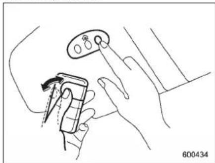
natural_image
Line drawing of a hand holding a small device with a knob, no text or symbols present-
Press and hold the desired HomeLink®button.
-
Pressandrelease("cycle") the hand-held transmitter button every 2 seconds until step 6 is complete.
- When the indicator light flashesslowly and then rapidly after several seconds, release both buttons.
- Plugthemotoroftheentrancegate/garagedooropenertotheoutlet.
- Testyouentrancegate/garagedoor
openerbypassingtheprogrammed HomeLink®button.
■ Programmingotherdevices
Toprogramotherdevicessuchasdoor locks, homelightingandsecuritysystems, contactHomeLinkatwww.homelink.com orcall1-800-355-3515.
■OperatingtheHomeLink® WirelessControlSystem
Onceprogrammed, the HomeLink® WirelessControlSystem can be used to remote-control the device which its buttons are programmed. To activate a device, simply press the appropriate button. The indicator light illuminates, indicating that the signal is being transmitted.
■Reprogrammingasingle HomeLink®button
- PressandholdtheHomeLink®button youwishtoreprogram.DONOTrelease thebuttonuntilstep4hasbeencompleted.
-
When the Home Link® indicator light begins to flash slowly (after 20 seconds), position the hand-held transmitter of the device for which you wish to program the button at 1 to 3 inches (25 to 76 mm) away from the Home Link® buttons surface.
-
Pressandholdthehand-heldtransmitterbutton. The HomeLink® indicator lightwillflash, firstslowly and then rapidly.
- Whentheindicatorlightbeginstoflash rapidly, releasebothbuttons.
The programming for the previous device is now erased and thenew device can be operated by pushing the HomeLink® button.
■ ErasingHomeLink®button memory
NOTE
- Performingthisprocedureerases thememoryofallthepreprogrammed buttonssimultaneously.Thememory ofindividualbuttonscannotbeerased.
-
Itisrecommendedthatuponthe saleofthevehicle,thememoryofall programmed HomeLink® buttons be erasedforsecuritypurposes.
-
Pressandholdthetwooutsidebuttons until the indicator light begins to flash (after 20 seconds).
- Releasebothbuttons.
■Incaseaproblemoccurs
If you cannot activate a device using the corresponding HomeLink® button after programming, contact HomeLink at www.homelink.com or call 1-800-355-3515 for assistance.
6-22 Interiorequipment
Rearviewcamera(if equipped)
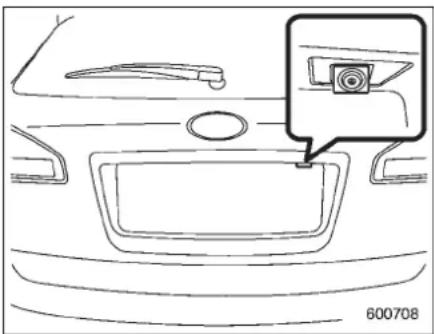
natural_image
Line drawing of a car interior showing the dashboard and rearview area with a camera icon (no text or symbols)Arearviewcameraisattachedtotherear gate. Whentheignitionswitchis "ON" and theselectleverissetto "R", therearview cameraautomaticallydisplaystherear viewimagebehindthevehicleonthe navigationmonitororontheinsidemirror.

WARNING
- Sincetherearviewcamerauses awide-anglelens, the image on themonitor is different from the actual view winterm sof distance.
- Sincetherangeoftheimageon themonitorislimited,youshould alwayschecktherearviewand
thesurroundingareawithyour eyesandmirrors,andmove backwardataslowspeed.Movingbackwardonlybychecking therearviewimagefromthe cameracouldcauseanaccident.
- Donotdisassembleormodify the camera, switchor wiring. If smokecomesoutoryousmell astrangeodor, stopusing the rearviewcameraimmediately. ContactyourSUBARUdealer foraninspection.Continueduse mayresultinaccident,fireor electricshock.

CAUTION
- If your vehicle is washed with a high-pressure washer, donot allow water to contact the camera directly. Entry of water in the cameralens may result in condensation, malfunction, fire or electric shock.
- Sincethecameraisaprecision device, donotsubjectittostrong impacts. Otherwise, malfunction, fireorelectricshockmayoccur.
- Ifmudorsnowstickstooris frozenonthecamera,youmust
be very careful removing it. Otherwise, damagedoneto the cameramay cause a fire or electric shock. Pour water or lukewarmwater over the camera to removemud and mice, and wipe it with asoft, dry cloth.
- Donotputaflameclosetothe cameraorwiring. Otherwise, damageorfiremayoccur.
- When replacing the fuse, besure touseafuse with the specified rating. Use of afuse with a different rating may result in a malfunction.
- If therearviewcameraisused for alongtimewhiletheengine is not operated, the battery may become completely discharged.
NOTE
- Donotwipethecamerawithalcohol, benzineorpaintthinner. Otherwise, discolorationmayoccur. Toremove contamination,wipethecamerawitha clothmoistenedwithadilutedneutral detergentandthenwipeitwithasoft, drycloth.
- Whenwaxingthevehicle, be careful nottoapplythewaxtothecamera. If it comes in contact with the camera,
moistenacleanclothwithadiluted neutraldetergenttoremovethewax.
- Thecameralenshashardcoatingto helppreventscratches.However,when washingthevehicleorcleaningthe cameralens,becarefulnottoscratch thecameralens.Donotuseawashing brushdirectlyonthecameralens.The monitorscreenmaybeadverselyaffected.
- Stronglightshinedonthecamera lensmaydevelopwhitelightstripes aroundthelightsource. This is not a malfunction.
●Underthefluorescentlight, the displaymayflicker. However, this is not a malfunction. - The image of therearview camera may be slightly different from the actual color of the objects.
■Howtousetherearview camera
When these elect leverissetto "R", therear viewcamera automatically display the rearviewimage from the vehicle. When the leverissetto other positions, the image beforesetting to "R" is displayed.
- Settheignitionswitchto"ON".
- Settheselectleverto "R".
NOTE
- The image of therearview camera has priority over others screen displays.
- The image of therearviewcamerais horizontally reversed asisthe case with the vehiclerearviewmirrororthe sideviewmirror.
- It may be difficult to see the image of therear view camera in the following cases. This is not a malfunction of the camera.
-Thevehicleisinadarkplace(at night, inatunnel, etc.).
—Thevehicleisinanextremelyhot orcoldplace.
- An object (such as raindrops, snow, dirt, etc.) that disturbsthe viewoftherearviewcamerasticks tothelensofthecamera.
-Stronglightshineddirectlyon thecameralens(occasionally,there areverticallinesonthescreen).
■Viewingrangeonthescreen
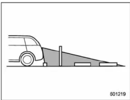
natural_image
Side view line drawing of a car on a slope with a vertical post and blocks, no text or symbols presentRangeofview
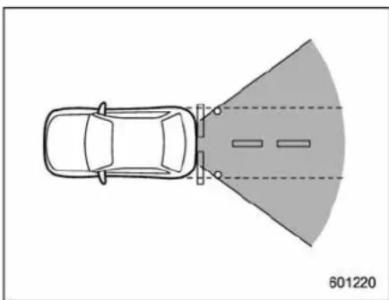
natural_image
Top-down diagram of a car with a road and traffic cone, no text or symbols presentRangeofview
-CONTINUED-
Interiorequipment
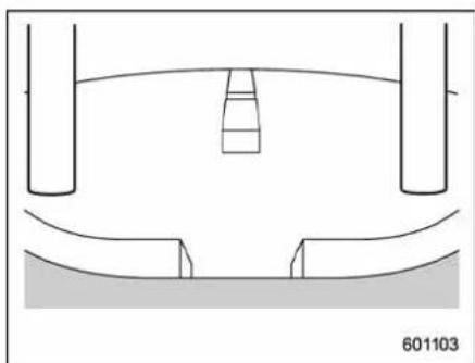
natural_image
Pure technical diagram showing a mechanical component with no text or symbolsImagefromcamera
The area from there are end of the bumper can be viewed. Areas at both end so the bumper and areas just under the bumper cannot be viewed.
Also, the image from therear view camera look shorter than the actual distance.

CAUTION
Therangethatcanbeviewedwith therearviewcameraislimited. Alwaysbesuretocheckwithyour eyeswhenmovingbackwardand proceedslowly.
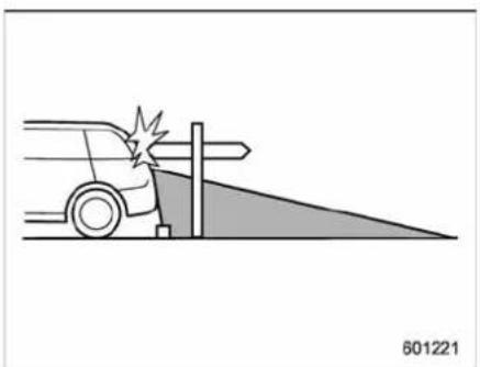
natural_image
Diagram of a car accident with a collision near a post and a triangular ground marker (no text or symbols)Rangeofview
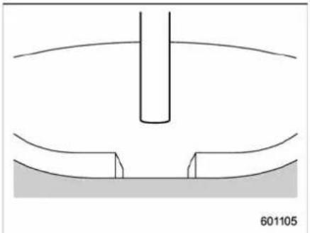
natural_image
Pure technical diagram showing a cylindrical component inserted into a curved base, with no text or symbols present.Imagefromcamera
Theareaabovethecameracannotbe viewed.Ifthereisanobjectthathasa wideprojectiononitsupperpartsuchasa signpolebehindthevehicle,theprojec-
tioncannotbeseenonthescreen.

CAUTION
Therangethatcanbeviewedwith therearviewcameraislimited. Alwaysbesuretocheckwithyour eyeswhenmovingbackwardand proceedslowly.
Helpline
Thehelpline(distancemarkerandvehicle widthline)isaguidetohelpyourealize theactualdistancefromthescreen.
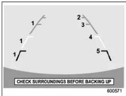
Helplinesdisplayedonthenavigation monitor
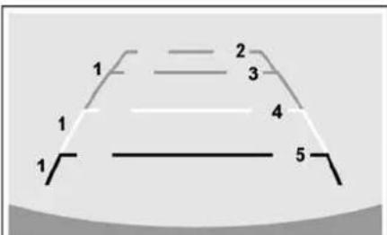
Check surroundings before backing up
601273
Helplinesdisplayedontheinsidemirror
1) Vehiclewidthline(obliqueverticalline)
2) Approx. 10 feet (3m) from the bumper (greenhorizontalline)
3) Approx. 6.5 feet (2m) from the bumper (green horizontalline)
4) Approx. 3 feet (1 m) from the bumper (yellow horizontalline)
5) Approx. 1.5 feet (0.5 m) from the bumper (red horizontalline)
Whentheselectleverissettoposition "R",themonitorscreendisplaysthehelp linestogetherwiththerearviewimage.

CAUTION
- Whenmovingbackward,always checkthebackwithyoureyes withoutrelyingonthehelplines.
•Theactualpositionmaybedif-
ferentfromtheindicationofthe helplines.
• Differencesmayoccurdueto numberofpassengersorloaded cargo.
- Whenthevehicleisonaslopeor whenthevehicleisinclined againsttheroad,theindication isdifferentfromtheactualposition.
▼Differencebetweenscreenandactualroad
The distance markers show the distance for a level road when the vehicle is not loaded. It may be different from the actual distance depending on the loading conditions or road conditions.
△Whenthereisanupwardslopeatthe back
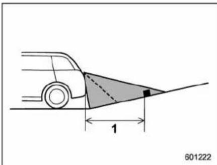
natural_image
Diagram of a car with a shaded triangular area and dimension line labeled '1', no text or symbols present.1)3feet(1m)
Thedistanceonthescreenlooksfarther thantheactualdistance.
△Whenthereisadownwardslopeat theback
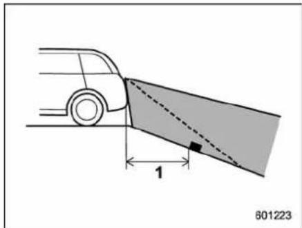
1)3feet(1m)
Thedistanceonthescreenlooksnearer thantheactualdistance.
NOTE
Whencargoisloaded,therearview distanceonthescreenlooksfarther thantheactualdistanceasinan upwardslope.
▼Featureofdistancemarker
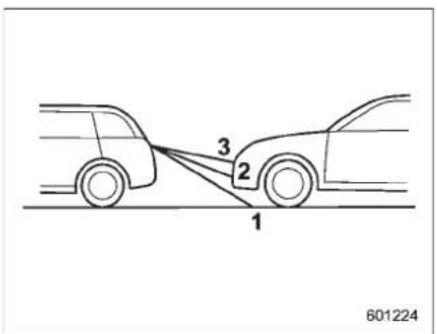
1)3feet(1m)line
2)6.5feet(2m)line
3)10feet(3m)line
The distance markers show the distance on the road. If there is a car or other object close behind, distance cannot be correctly displayed.
Starting and operating
Fuel....7-2
Fuelrequirements....7-2
Fuelfillerlidandcap....7-3
Stateemissiontesting(U.S.only)....7-5
Startingtheengine....7-7
Stoppingtheengine....7-8
Remoteenginestartsystem(dealeroption).....7-8
Startingyourvehicle....7-9
Remotestartsafetyfeatures....7-9
Enteringthevehiclewhileitisrunningviaremote start....7-9
Enteringthevehiclefollowingremoteenginestart shutdown....7-9
Pre-heatingorpre-coolingtheinteriorofthe vehicle....7-10
Servicemode....7-10
Remoteenginestarttransmitterprogramming andprogrammablefeatureoption....7-10
Systemmaintenance....7-11
Automatictransmission....7-12
Selectlever....7-13
Shiftlockfunction....7-14
Selectionofmanualmode....7-16
Driving tips 7-17
SPORT mode 7-18
Power steering.... 7-18
Braking 7-19
Braking tips.... 7-19
Brake system 7-19
Discbrakepadwearwarningindicators.... 7-20
ABS(Anti-lockBrakeSystem)....7-20
ABSsystemself-check.... 7-21
ABSwarninglight.... 7-21
ElectronicBrakeForceDistribution(EBD)
system....7-22
Steps to take if EBD system malfunctions ..... 7-22
VehicleDynamicsControlsystem....7-23
Vehicle Dynamics Control system monitor.... 7-25
Traction Control system OFF switch.... 7-27
Tirepressuremonitoringsystem(TPMS)......7-28
Parkingyourvehicle....7-29
Parking brake 7-29
Parking tips 7-30
Cruise control 7-30
To set cruise control.... 7-31
To temporarily cancel the cruise control.... 7-31
To turn off the cruise control.... 7-32
To change the cruising speed 7-32
Cruisecontrolindicatorlight.... 7-33
Cruisecontrolsetindicatorlight.... 7-33
7-2 Starting and operating
Fuel

CAUTION
Useofafuelwhichislowinquality oruseofaninappropriatefuel additivemaycauseenginedamage.
Fuelrequirements
Theengineisdesignedtooperateusing unleadedgasolinewithanoctanerating of87AKlorhigher.
▼Fueloctanerating
Thisoctaneratingistheaverageofthe ResearchOctaneandMotorOctane numbersandiscommonlyreferredtoas theAntiKnockIndex(AKI).
Usingagasolinewithaloweroctane ratingcancausepersistentandheavy knocking,whichcandamagetheengine. Donotbeconcernedifyourvehicle sometimesknockslightlywhenyoudrive upahillorwhenyouaccelerate.Contact yourSUBARUdealerifyouuseafuelwith thespecifiedoctaneratingandyour vehicleknocksheavilyorpersistently.
▼Unleadedgasoline
Theneckofthefuelfillerpipeisdesigned toacceptonlyanunleadedgasolinefiller nozzle.Undernocircumstances should leaded gasolinebeusedbecauseitwill damagetheemissioncontrolsystemand mayimpairdriveabilityandfueleconomy.
▼Californiafuel
IfyourvehiclewascertifiedtoCalifornia EmissionStandardsasindicatedonthe underhoodtune-uplabel,itisdesignedto optimizeengineandemissioncontrol systemperformancewithgasolinethat meetsthecleanburninglow-sulfurCaliforniagasolinespecifications.Ifyoulivein anyotherstatethanCalifornia,your vehiclewilloperateongasolinemeeting Federalspecifications.GasolinesoldoutsideCaliforniaispermittedtohavehigher sulfurlevels,whichmayaffecttheperformanceofyourvehicle'scatalyticconverter andmayproduceasulfurexhaustodoror smell.SUBARUrecommendsthatyoutry adifferentbrandofunleadedgasoline havinglowerssulfurtodetermineifthe problemisfuelrelatedbeforereturning yourvehicletoanauthorizeddealerfor service.TheCHECKENGINEwarning light/Malfunctionindicatorlampmayalso illuminate.Ifthisoccurs,returntoyour authorizedSUBARUdealerfordiagnosis. Ifitisdeterminedthattheconditionis causedbythetypeoffuelused,repairs maynotbecoveredbyyourwarranty.
▼MMT
Some gasoline contains an octane-enhancing additive called MMT (Methylcyclopentadienyl Manganese Tricarbonyl). If you use such fuels, you remission control system performancemay deteriorate and the CHECK ENGINE warning light/Mal-function indicator lamp may illuminate. If this happens, return to your authorized SUBARU dealer for service. If it is determined that the condition is caused by the type of fuel used, repairs may not be covered by your warranty.
▼Gasolineforcleanerair

CAUTION
Donotletfuelspillontheexterior surfacesofthevehicle.Fuelscontainingalcoholmaycausepaint damage,whichisnotcoveredunder theSUBARULimitedWarranty.
Youruseofgasolinewithdetergent additiveswillhelppreventdepositsfrom forminginyourengineandfuelsystem. Thishelpskeepyourengineintuneand youremissioncontrolsystemworking properly, andisawayofdoingyourpart forcleanerair. If youcontinuouslyusea highqualityfuelwiththeproperdetergent andotheradditives,youshouldnever
needtoaddanyfuelsystemcleaning agentstoyourfueltank.
Many gasolines are now blended with material called oxygenates. Use of these fuel can also help keep the air cleaner. Oxygenated blend fuels, such as MTBE (Methyl Tertiary Butylether) or ethanol (ethyl or grain alcohol) may be used in your vehicle, but should contain nomore than 15% MTBE or 10% ethanol for the proper operation of your SUBARU. In addition, some gasolines suppliers are now producing reformulated gasolines, which are designed to reduce vehicle emissions. SUBARU approves the use of reformulated gasoline.
If you are not sure what the fuel contains, you should ask your service station operators if their gasolines contain detergents and oxygenates and if they have been reformulated to reduce vehicle emissions.
Asadditionalguidance,onlyusefuels suitedforyourvehicleasexplainedinthe following.
●Fuelshouldbeunleadedandhavean octaneratingnolowerthanthatspecified inthismanual.
●Methanol(methylorwoodalcohol)is sometimesmixedwithunleadedgasoline.
Methanolcanbeusedinyourvehicle ONLYifitdoesnotexceed5%ofthefuel mixtureANDifitisaccompanied by sufficient quantities of the propercosol-vents and corrosion inhibitors required to prevent damage to the fuel system. Donot use fuel containing methanol EXCEPT under these conditions.
- Ifundesirabledriveabilityproblemsare experiencedandyoususpecttheymaybe fuelrelated,tryadifferentbrandofgasolinebefore seekingservice atyour SUBARUdealer.
- Fuelsystemdamageordriveability problemswhichresultfromtheuseof improperfuelarenotcoveredunderthe SUBARULimitedWarranty.
■ Fuelfillerlidandcap
Refueling
Onlyonepersonshouldbeinvolvedin refueling. Donotallowotherstoapproach theareaofthevehiclenearthefuelfiller pipewhilerefuelingisinprogress. Besuretoobserveanyotherprecautions thatarepostedattheservicestation.
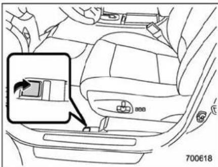
- Toopenthefuelfillerlid, pullthelid releaseleverup. The leverisonthefloor attheleftofthedriver'sseat.
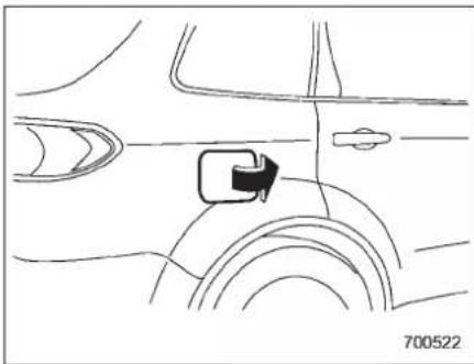
natural_image
Diagram of a car's side profile showing lane markings and a directional arrow (no text or symbols)- Openthefuelfillerlid.
-CONTINUED-
7-4 Starting and operating

WARNING
Beforeopeningthefuelfillercap, firsttouchthevehiclebodyora metalportionofthefuelpumpor similarobjecttodischargeany staticelectricitythatmaybepresent onyourbody.Ifyourbodyiscarry-inganelectrostaticcharge,thereis apossibilitythatanelectricspark couldignitethefuel,whichcould burnyou.Toavoidacquiringanew staticelectriccharge,donotget backintothevehiclewhilerefueling isinprogress.
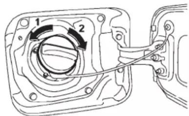
700304
1) Open
2) Close
- Removetheuelfillercapbyturningit slowlycounterclockwise.

WARNING
- Gasoline vapor is highly flammable. Before refueling, always first stop the engine and close all vehicle doors and windows. Makesure that there are no lighted cigarettes, open flames or electrical sparks in the adjacent area. Refueling must be performed outside. Quickly wipe up any spilled fuel.
- Whenopeningthecap, grasp it firmly and turnits slowly to the left. Donotremovethecap quickly. Fuel maybe under pressure and spray out of the fuel filler neck, especially in hot weather. If you hearahissing sound while you are removing the cap, wait forthesound to stop and then slowly open the cap to prevent fuel from spraying out and creating a fire hazard.
- When refueling, insert the fuel nozzlesecurelyintothefuelfiller pipe.Ifthenozzleisliftedornot fullyinserted,itsautomaticstoppingmechanismmaynotfunc-
tion, causing fuel too overflow the tank and creating a fire hazard.
- Stop refueling when the automatic stop mechanism on the fuelnozzleactivates. If you continue to add fuel, temperature changes or other conditions may cause fuel too overflow from the tank and create a fire hazard.
- Stopfillingthetankafterthefuelfiller pumpautomaticallyturnsoff.Do notadd anymorefuel.

CAUTION
Makesurethatthecapistightened untilitclickstoppreventfuelspillage intheeventofanaccident.
-
Putthecapbackon, turnitclockwise until you hear a clicking noise. Becertain not to catch the tether under the cap while tightening.
-
Closethefuelfillerlidcompletely. Ifyouspillanyfuelonthepaintedsurface, rinseitoffimmediately. Otherwise, the paintedsurfacecouldbedamaged.
NOTE
200253
- Youwillseethe""sighinthefuel gauge. This indicates that the fuel filler door (lid) is located on the right side of the vehicle.
- If the fuelfillercapis not tightened until clicks or if the tether is caught under the cap, the CHECK ENGINE warning light/malfunction indicator lamp may illuminate. Referto "CHECK ENGINE warning light/Malfunction indicator lamp" 3-12.

CAUTION
- Neveraddanycleaningagentsto thefueltank. The addition of a cleaningagent may caused a
magetothefuelsystem.
- Afterrefueling,turnthecaptothe rightuntilitclickstoensurethat itisfullytightened.Ifthecapis notsecurelytightened,fuelmay leakoutwhilethevehicleisbeing drivenorfuelspillagecould occurintheeventofanaccident, creatingafirehazard.
- Donotletfuelspillontheexterior surfacesofthevehicle.Because fuelmaydamagethepaint,be suretowipeoffanyspilledfuel quickly.Paintdamagecausedby spilledfuelisnotcoveredunder theSUBARULimitedWarranty.
●AlwaysuseagenuineSUBARU fuelfillercap.Ifyouusethe wrongcap,itmaynotfit,and yourfueltankandemissioncontrolsystemmaybedamaged.It couldalsoleadtofuelspillage andafire. - Immediatelyputfuelinthetank wheneverthelowfuelwarning lightilluminates.Enginemisfires asaresultofanemptytank couldcausedamagetotheengine.
Stateemissiontesting(U.S. only)

WARNING
TestingofanAll-WheelDrivemodel mustNEVERbeperformedona singletwo-wheeldynamometer.Attemptingtodosowillresultin uncontrolledvehiclemovementand maycauseanaccidentorinjuriesto personsnearby.

CAUTION
Resultantvehicledamagedueto impropertestingisnotcovered undertheSUBARU Limited Warr- ranty and istheresponsibilityof thestateinspectionprogramorits contractorsorlicensees.
Atstateinspectiontime,rememberto tellyourinspectionorservicestationin advancenottoplaceyourSUBARU AWDvehicleonatwo-wheeldynamometer. Otherwise, serioustransmissiondamagewillresult.
Somestateshavestartedusingdynamometersintheirstateinspectionprograms
-CONTINUED-
7-6 Starting and operating
inordertomeettheirobligationunder federallawtoimplementstrictervehicle emissionstandardstoreduceairpollution fromvehicles. Adynamometerisatread- millorroller-liketestingdevicethatallows yourvehicle'swheelstoturnwhilethe vehicleremainsinoneplace. Depending ontheseverityofastate'sairpollution problems, thestatesmustadopteithera "basic" or "enhanced" vehicle emission inspectiontest. Normally, aportionofthe basicemissiontestconsistsofanemis- sioninspectorinsertingananalyzerprobe intotheexhaustpipeofanidlingvehicle forashortperiodoftime. Stateswithmore severeairpollutionproblemsarerequired toadoptanenhancedvehicleemission test. Thistestsimulatesactualdriving conditionsonadynamometerandpermits moreaccuratemeasurementoftailpipe emittedpollutionthanthebasicemission test.
The U.S. Environmental Protection Agency (EPA) and states using two-wheel dynamometers in theiremission testing program have EXEMPTEDSUBARU AWD vehicles from the portion of the testing program that involves two-wheel dynamometer.
Therearesomestatesthatusefour-wheel dynamometersintheirtestingprograms. Whenproperlyused,thatequipmentwill
notdamageaSUBARUAWDvehicle. Undernocircumstanceshouldtherear wheelsbejackedofftheground, nor shouldthedriveshaftbedisconnectedfor stateemissiontesting.
The EPA has issued regulations for inspecting the On-Board Diagnostic (OBD) system as part of the state emissions inspection. The OBD system is designed to detect engine and transmission problem that might cause vehicle emission to exceed allowable limits. These inspections apply to all 1996 model year and newer passenger cars and light trucks. Over 30 states plus the District of Columbia have implemented the OBD system inspection.
- TheinspectionoftheOBDsystem consistsofavisualoperationalcheckof the"CHECKENGINE"warninglight/malfunctionindicatorlamp(MIL)andan examinationoftheOBDsystemwithan electronicscantoolwhiletheengineis running.
- A vehicle passestheOBDsystem inspectionifproperthe“CHECKEN-GINE”warninglight/MILilluminationis observed, there is no stored diagnostic troublecodes,andtheOBDsystem readinessmonitorsarecomplete.
- Avehicle failstheOBDinspectionifthe
"CHECK ENGINE" warning light/MIL is not properly operating or there is one or more diagnostic trouble codes stored in vehicle's computer with the "CHECK ENGINE" warning light/MIL illuminated.
- Astateemissioninspectionmayreject (notpassorfail)vehicleifthenumberof OBDsystemreadinessmonitors"Not Ready"isgreaterthanone.Underthis condition,thevehicleoperatorshouldbe instructedtodrivehis/hervehicleforafew daystosetthemonitorsandreturnforan emissionre-inspection.
- Ownersofrejectedorfailingvehicles shouldcontacttheirSUBARUDealerfor service.
Preparingtodrive
You should perform the following checks and adjustment every day before you start driving.
- Check that all windows, mirrors, and lights are clean and unobstructed.
- Check the appearance and condition of the tires. Also check tires for proper inflation.
- Lookunderthevehicleforanysignof leaks.
- Check that the hood and reargate are fully closed.
- Checktheadjustmentoftheseat.
- Checktheadjustmentoftheinside andoutsidemirrors.
- Fastenyourseatbelt. Check that your passengers have fastened their seat belts.
- Check the operation of the warning and indicator lights when the ignition switchisturned to the "ON" position.
- Check the gauges, indicator and warning lights after starting the engine.
NOTE
Engineoil, enginecoolant, brakefluid, washerfluid and other fluid levels should be checked daily, weekly or at fuel stops.
Startingtheengine

CAUTION
- Donotoperatethestartermotor continuouslyformorethan10 seconds. If the engine fail to start after operating the starter for 5 to 10 seconds, wait for 10 seconds or more before trying again.
-
If you restart the engine while the vehicle is moving, shift these select lever into the "N" position. Do not attempt to place these select lever of moving vehicle into the "P" position.
-
Apply the parking brake.
- Turnoffunnecessarylightsandaccessories.
- Shift the select lever to the "P" or "N" position (preferably "P" position). The starterwillonlyoperatewhentheselect lever is at the "P" or "N" position.
- Turntheignitionswitchtothe "ON" positionandchecktheoperationofthe warningandindicatorlights. Referto "Warning and indicator lights" 3-9.
- Turntheignitionswitchtothe"START" positionwithoutdepressingtheaccelera-
torpedal. Releasethekeyimmediately aftertheenginehasstarted. Iftheenginedoesnotstart,trythe following.
(1)Turntheignitionswitchtothe "LOCK"positionandwaitforatleast 10seconds. Aftercheckingthatthe parkingbrakeisfirmlyset,turnthe ignition switch to the "START" position whiledepressingtheacceleratorpedal slightly(approximatelyaquarterofthe fullstroke).Releasetheaccelerator pedalassoonastheenginestarts.
(2) If this failst o start the engine, turn the ignition switch back to the "LOCK" position and wait for at least 10 seconds. Then fully depress the accelerator pedal and turn the ignition switch to the "START" position. If the engine starts, quickly release the accelerator pedal.
(3) If this fail starts to start the engine, turn the ignition switch againto the "LOCK" position. After waiting for 10 seconds or longer, turn the ignition switch to the "START" position without depressing the accelerator pedal.
(4) If the engine still refuse to start, contact your nearest SUBARU dealer for assistance.
- Confirm that all warning and indicator light shaveturned off after the engine has
-CONTINUED-
7-8 Starting and operating
started. The fuel-injectionsystema-
matically lower the didlespeed as the
enginewarmsup.
While the engine is warming up, make sure that these select leveris at the "P" or "N" position and that the parking brake is applied.
NOTE
- Theenginemaybedifficulttostart whenthebatteryhasbeendisconnectedandreconnected(formaintenanceorotherpurposes).Thisdifficultyiscausedbytheelectronically controlledthrottle'sself-diagnosis function.Toovercomeit,keepthe ignitionswitchinthe"ON" position forapproximately10secondsbefore startingtheengine. - Toprotecttheenginewhile the select lever is in the "P" or "N" position,theengineiscontrolledso thattheenginespeedmaynotbecome toohigheveniftheacceleratorpedalis depressedhard.
Stoppingtheengine
WARNING
Donotstoptheenginewhenthe vehicleismoving. This will cause lossof powertothepowersteering and the brake booster, making steering and braking more difficult. It could also result in accidental activation of the "LOCK" position on the ignitionswitch, causing the steering wheel to lock.
The ignition switch should be turned off onlywhenthevehicleisstoppedandthe engineisidling.
Remoteenginestartsystem (dealeroption)
WARNING
- Donotstarttheengineusing the remotestartsysteminanenclosedenvironment (e.g. closed garage). Prolonged operation of amotor vehicleinan enclosed environmentcancause a harmful build-upofCarbonMonoxide. CarbonMonoxideisharmfulto yourhealth.Exposuretohigh levelsofCarbonMonoxidecan causeheadaches,dizzinessorin extremecasesunconsciousness and/ordeath.
- Beforeperforminganyservicing ofthevehicle,temporarilyplace theremoteengine startsystemin servicemodetopreventthe systemfromunexpectedlystartingtheengine.
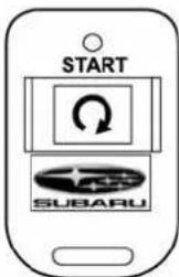
700502
■ Startingyourvehicle
Theremoteengine startsystemisactivated bypressing the " button twice within 3 secondson your remote engine start transmitter. Thesystem will check certain pre-conditions before starting, and ifallsafety parameters are correct, the engine will start within 5 seconds. While the vehicle is operating via remote engine start, the vehicle's power window features will be disabled. Also, the system has a timer and will shutdown after 15 minutes if you donot operate the vehicle. Press and hold the " button for 2 seconds again to turn the vehicle off. If the vehicle's starter cranks but does not start or start and stalls, theremote engine starts system will power off then attempt to start the vehicle anadditionalfourtimes.Ifthevehiclefails tostartaftertheadditionalattempts,the remoteenginestartsystemwillabortand returntoanonactivatedstate.
■ Remotestartsafetyfeatures
Forsafetyandsecurityreasons,the systemwillfailtostartandbeepthehorn twiceorshutdowntheengine during remotestartoperationifanyofthe followingoccur:
●Thebrakepedalisdepressedbefore thevehicleignitionswitchisturned"on"
●Thekeywasalreadyintheignition switch
•Theenginehoodisopened
- Thevehicle'sengineidlespeedhas reachedalevelover3,000RPM
●Thealarmistriggeredbyopeningany ofthedoorsorthereargate.
NOTE
- Theseurityindicatorlightonthe dashboardwillstopflashingwhile underremoteenginestartoperation, butthevehicleisstillprotected.
- If the vehicle is entered during remote engine start operation, the system will not record entry in the alarm history.
■ Enteringthevehiclewhileit isrunningviaremotestart
- Unlockthevehicledoorsusingthe remotekeylessentrysystem.Ifthevehicle'sdoorsareunlockedmanuallyusing thekey,thevehicle'salarmsystemwill triggerandtheremoteenginestartsystem willturnoff.Insertingthekeyintothe ignitionswitchandturningittothe"ON" positionorpressingtheunlockbutton" ontheremotekeylessentrytransmitter willdisarmthealarmsystem.Referto "Alarmsystem" or 2-16.
- Enterthevehicle.Donotdepressthe brakepedal.
- Insertthekeyintotheignitionswitch andturntothe"ON"position.Iftheignition switchisaccidentallyturnedtothe "START" position, the system's "starter anti-grind"featurewillpreventthestarter fromre-cranking.
- Depressthebrakepedal. Theremote starterdisengages, the vehicle's power window features arere-enabled and the vehicle will operate normally.
■ Enteringthevehiclefollowingremoteenginestartshutdown
Analarmtriggermayoccurifthevehicleis openedbytheremotekeylessentry
-CONTINUED-
7-10 Starting and operating
transmitterwithinafewsecondsimmediatelyfollowingremoteenginestartshutdown.
■ Pre-heatingorpre-cooling theinteriorofthevehicle
Before exiting the vehicle, set the temperature control so the desired setting and operation. After the system starts the vehicle, the heater or air-conditioning will activate and heat or cool the interior to your setting.
Servicemode
Inservicemode,theremotestartfunction istemporarilydisabledtopreventthe systemfromunexpectedlystartingthe enginewhilebeingserviced.
▼Toengagetheservicemode
Turntheignitionswitchtothe"ON" position, depressandholdthebrakepedal then, pressandreleasethe " 🔒"buttonon theremoteenginestarttransmitterthree times. Thesystemwillpausefor1second andthenflashtheparkinglightsandhonk thehornthreetimesindicatingthatthe systemisinservicemode. Whenattemptingtoactivatetheremotestartsystem whileinservicemode, theparkinglights willflashandthehornwillhonktwotimes andwillnotstart.
▼Todisengagetheservicemode
Turntheignitionswitchtothe"ON" position, depressandholdthebrake pedal, thenpressandreleasethe" buttonotheremoteenginestarttransmitterthreetimes. Thesystemwillpause for1secondandflashtheparkinglights onetimeindicatingthatthesystemhas exitedservicemode.
NOTE
Whentakingyourvehicleinforservice, itisrecommendedthatyouinformthe servicepersonnelthatyourvehicleis equippedwitharemoteenginestart system.
■ Remoteenginestarttransmitterprogrammingandprogrammablefeatureoption
Newtransmitterscanbeprogrammedto theremoteenginestartsysteminthe eventthatremoteenginestarttransmitters arelost,stolenordamaged.Theremote enginestartsystemalsohasoneprogrammablefeaturethatcanbeadjusted foruserpreference.
Theremoteenginestartsystemcanbe programmedtoeithermakeanaudible hornchirpuponremotestartactivationor not.Remoteenginestarttransmitterprogrammingandfeatureprogrammingcan

beadjustedusingthefollowingprocedure.
- Openthedriver'sdoor(thedriver's doormustremainopenedthroughoutthe entireprocess).
- Insertthekeyintothevehicle'signition switchandturntothe"ON"position.
- Locatethesmallblackprogramming buttonbehindthefuseboxcover,onthe driver'ssideleftunderthedashboard panel.
- Pressandholdtheblackprogramming buttonfor10to15seconds.Thehornwill honkandtheparkinglightswillflashthree timestoindicatethatthesystemhas enteredprogrammingmode.Atthispoint youcanperformeitheraction(step5or step6).
- Toprogram aremote transmitter: pressandreleasethe“ 📄”buttononeach transmitter.Thehornwillhonkandthe parkinglightswillflashonetimetoindicate asuccessfultransmitterlearneachtime the“ 📄” buttonispressed.You can programuptoeighttransmitters.
- TotoggletheHornConfirmationchirps ON/OFF:pressandreleasethebraketo togglethefeature.Thehornwillchirpand theparkinglightswillflashonetimeto indicateConfirmationHornChirpsare "OFF".Thehornwillhonkandtheparking lightswillflash2timestoindicateConfirmationHornChirpsare"ON".Depres-
singthebrakepedalrepeatedlywilltoggle thefeatureONorOFFeachtime.
- To exit theremotetransmitter and feature programming mode, turn the ignitions switch to the "LOCK" position, remove the key from the ignitions switch and test operation of theremotetransmitter(s) and horn confirmation feature.
■ Systemmaintenance
▼Changingthebatteries
CAUTION
- Donotletdust, oilorwatergeton orintheremoteenginestart transmitterwhenreplacingthe battery.
- Becarefulnottodamagethe printedcircuitboardintheremoteenginestarttransmitter whenreplacingthebattery.
- Becarefulnottoallowchildrento touchthebatteryandanyremovedparts;childrencould swallowthem.
- Thereisadangerofexplosionif anincorrectreplacementbattery isused.Replaceonlywiththe same or equivalent type of battery.
- Batteriesshouldnotbeexposed to excessive heat such as sunshine,fireorthelike.
Thetwo3-voltlithiumbatteries(model CR-1220) supplied in your remote engine start transmitters should last approximately three years, depending on usage. When the batteries begin to weaken, you will notice a decrease in range (distance from the vehicle that your remote engine starts system operates). Follow the instructions below to change her remote control batteries.
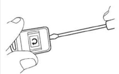
natural_image
Line drawing of a hand holding a handheld device with a circular button labeled 'C' (no text or symbols on the device itself)700503
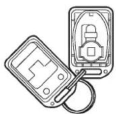
natural_image
Line drawing of two electronic device components with no visible text or symbols700390
- Carefullypry theremoteenginestart transmitterhalvesapartusingasmallflatheadscrewdriver.
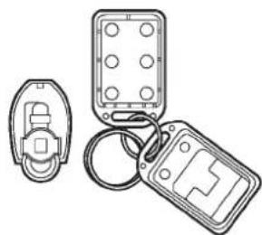
natural_image
Line drawing of three electronic components: a remote control case, a rectangular panel with circular holes, and a key inserted into a slot (no text or symbols)700391
-CONTINUED-
7-12 Starting and operating
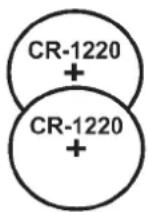
700392
- Removethecircuitboardfromthe bottomhalfofthecaseandslidethewhite plasticbatteryholderoutfromunderthe batterytabreleasingthebatteries. Removetheoldbatteriesandreplacewith newones.Besuretoobservethe(+)sign ontheoldbatteriesbeforeremovingthem toensurethatthenewbatteriesare insertedproperly(battery“+”shouldbe pointedawayfromthetransmittercircuit boardonbothbatteries).
- Carefullysnapthecasehalvesback together, thentesttheremoteenginestart system.
NOTE
This device complies with Part 15 of the FCC Rules and with RSS-210 of Industry Canada. Operation is subject
tothefollowingtwoconditions:(1)This devicemaynotcauseharmfulinterference,and(2)this device must acceptanyinterferencereceived,includinginterferencethatmaycause undesiredoperation.
Changes or modifications not expressly approved by the party responsible for compliance could void the user's authority to operate the equipment.
Automatictransmission
The automatic transmission is electronically controlled and provides 5 forward speeds and 1 reversespeed. Also, it has a manual mode and a SPORT mode.

WARNING
Do not shift from the "P" or "N" position into the "D" or "R" position while depressing the accelerator pedal. This may cause the vehicle to jump forward or backward.

CAUTION
- Shift into the "P" or "R" position only after the vehicle is completely stopped. Shifting while the vehicle is moving may cause damage to the transmission.
- Do not race the engine for more than5secondsinanyposition except the "N" or "P" position whenthebrakeissetorwhen chocksareusedinthewheels. Thismaycausetheautomatic transmissionfluidtooverheat.
- Avoidshiftingfromoneofthe forwarddrivingpositionsintothe
“R”positionorviceversauntil the vehicle has completely stopped. Such shifting may caused damage to the transmission.
- Whenparkingthevehicle,first securelyapplytheparkingbrake andthenplacetheselectleverin the“P”position.Avoidparking foralongtimewiththeselect leverinanyotherpositionas doingsocouldresultinadead battery.
NOTE
- When the engine coolant temperature is still low, the automatic transmission will up shift to higher engine speed than when the coolant temperature is sufficiently high in order to shortent hewarm - uptime and improve drive ability. The gear shift timing will automatically shift to then normal timing after the engine has warmed up. - Immediately after ATF (automatic transmission fluid) is replaced, you may feel that the automatic transmission operation is somewhat unusual. This results from invalidation of data which the on-board computer has collected and stored in memory to
allowthetransmissionoshiftatthe mostappropriatetimesforthe current conditionofyourvehicle.Optimized shiftingwillbe restoredasthevehicle continuestobedrivenforawhile.
■Selectlever
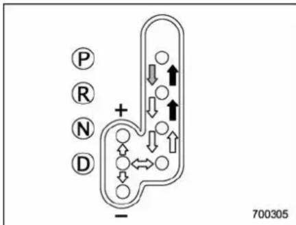
→:Withthebrakepedaldepressed,shift whilepressingthebuttonin.
→:Shiftwhilepressingthebuttonin. →:Shiftwithoutpressingthebutton.
Theselectleverhasfourpositions, "P", "R", "N", "D" and also has manual gate for using "SPORT" modeormanualmode.
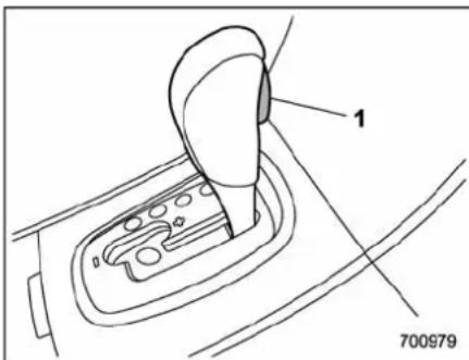
1) Selectleverbutton
▼P(Park)
Thispositionisforparkingthevehicleand startingtheengine.
In this position, the transmission is mechanically locked to prevent the vehicle from rolling freely.
When you park the vehicle, first set the parking brake fully, then shift into the "P" position. Donothold the vehicle with only the transmission.
To shift the select lever from the "P" to any other position, you havetodepress the brake pedalfully then push these elect lever button on the lever knob when the ignitionswitchisin the "ON" position. This prevents the vehicle from lurching when it
-CONTINUED-
7-14 Starting and operating
isstarted.
If theselectleverdoesnotmovefrom the "P" position with the brakepedaldepressed, theselectleverbutton pushed in, and the ignitionswitchintheON position, referto "Shiftlockfunction" 7-14.
▼R(Reverse)
Thispositionisforbackingthevehicle.
To shift from the "N" to "R" position, stop the vehicle completely then movethe levertothe "R" positionwhilepushing theselectleverbutton.
▼N(Neutral)
Thispositionisforrestartingastalled engine.
In this position the wheels and transmission are not locked. In this position, the transmission is neutral; the vehicle will roll freely, even on the slightest incline unless the parking brake or footbrake is applied. Avoid coasting with the transmission neutral.
Duringcoasting, thereisnoenginebrakingeffect.
NOTE
Whentheignitionswitchhasbeen turnedtothe"LOCK"position, movementoftheselectleverfromthe"N"
positiontothe“R”positionispossible foralimitedtimeperiodbydepressing thebrakepedalandthenbecomes impossible.Iftheselectleverbecomes impossibletobemovedafteralimited timeperiod,turntheignitionswitchto the “ON” position. You will then be able tomovetheselectlevertothe“P” position.

WARNING
Donotdrivethevehiclewiththe selectleverinthe“N”(Neutral) position. Enginebrakinghasno effectinthisconditionandtherisk ofanaccidentis consequentlyincreased.
▼D(Drive)
Thispositionisfornormaldriving.
Thetransmissionautomaticallyshiftsinto a suitable gear from 1st to 5th according to thevehiclespeedandtheacceleration yourequire.
When more acceleration is required in this position, depress the accelerator pedal fully to the floor and hold that position. The transmission will automatically downshift to 4th, 3rd, 2nd or 1st gear. When you release the pedal, the transmission will
returntotheoriginalgearposition.
TousetheSPORTmode, movethelever from this position into the manual gate.
Tousethemanualmode, movethelever from this position into the manual gate then move it toward the "+" and "-" ends.
Whileclimbingagrade
When driving up a hill, undesired upshift to 4thor5thgearispreventedfromtaking placewhen the accelerator isreleased. Thisminimizesthechanceofsubsequent downshiftingtoalowergearwhenacceleratingagain. Thispreventsrepeated upshiftinganddownshiftingresultingina smootheroperationofthevehicle.
NOTE
The transmission may downshift to 2nd or1stgear,dependingonthewaythe acceleratorpedalisdepressedtoacceleratethevehicleagain.
Shiftlockfunction
Theshiftlockfunctionhelpspreventthe improperoperationoftheselectlever.
- The select lever cannot be operated unless theignitionswitchisturned to the "ON" position and the brakepedalis depressed.
- The select lever cannot be moved from
the "P" position to any other position before the brake pedal is depressed. Depressthebrakepedal first, and then operatetheselect lever.
- Onlythe"P"positionallowsyoutoturn thekeyfromthe"Acc"positiontothe "LOCK"positionandremovethekeyfrom theignitionkeycylinder.
- If the ignitions switch is turned to the "LOCK" position while these select lever in the "N" position, these select lever may not be moved to the "P" position after a period of time. Therefore, movetheselect lever to the "P" position with the brake pedal depressed soon after the ignitions switch is turned to the "LOCK" position.
▼Shiftlockrelease
If theselect lever cannot be operated, turn the ignitions switch back to the "ON" position then movetheselect lever to the "P" position with theselect lever button pressed and brake pedal depressed.
If theselectleverdoesnotmoveafter performingtheaboveprocedure,perform thefollowingsteps.
- Whentheselectlevercannot be shifted from "P" to "N":
Referto"Shiftlockreleaseusingtheshift lockreleasebutton" 7-15. - Whentheselectlevercannotbe
shifted from "N" to "R" or "P": Within60secondsafterplacingtheigni- tionswitchinthe"Acc"position,movethe select lever to the "R" or "P" position with theselectleverbuttonpressedandbrake pedaldepressed.
If you must perform the above procedure, the shift lock system (or the vehicle control system) may be malfunctioning. Contact a SUBARU dealer for an inspection as soon as possible.
If these select lever does not move after performing the above procedure, refer to "Shift lock release using the shift lock release button" or 7-15.
▼Shiftlockreleaseusingtheshift lockreleasebutton
Perform the following procedure to release the shiftlock.
- Apply the parking brake and stop the engine.
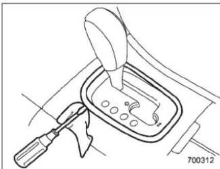
natural_image
Line drawing of a car gear shift lever with a tool and screwdriver (no text or symbols)- Removethecoverbypryingonthe edgewithaflat-headscrewdriver.
NOTE
Topreventdamagetothecover, wrap thetipoftheflat-headscrewdriverwith vinyltapeoraclothbeforeremoving thecover.
7-16 Starting and operating
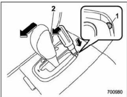
1) Shiftlockreleasebutton
2) Selectleverbutton
- Movetheselectleverwhileperforming the following operations.
●Depressingthebrakepedal
- Pushingtheshiftlockreleasebutton usingascrewdriver
- Pushingtheselectleverbutton
If theselectleverdoesnotmoveafter performingtheaboveprocedure, theshift locksystemmaybemalfunctioning. ContactaSUBARUdealerforaninspection as soonaspossible.
■Selectionofmanualmode
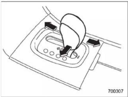
natural_image
Line drawing of a car gear shift lever with arrows indicating motion (no text or symbols)Withthevehicleeithermovingorstationary,movetheselectleverfromthe“D”positiontothemanualgatethenmoveitto the “+” end or “-” end of the manual gate toselectmanualmode.
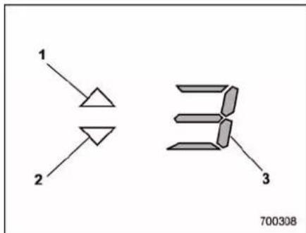
1) Upshift indicator
2)Downshiftindicator
3) Gearpositionindicator
Whenthemanualmodeisselected, the gearpositionindicatorandupshiftindicatorand/ordownshiftindicatorinthe tachometerilluminate. The gearposition indicatorshowsthecurrentlyselected gearinthe1st-to-5th-gearrange. The upshiftanddownshiftindicatorsshow whenagearshifthispossible. Whenthe upshiftindicator" △"isilluminated, up-shiftingispossible. Whentedownshift indicator" ▽"isilluminated, downshifting ispossible. Whenbothindicators are illuminated, upshiftinganddownshifting arebothpossible. Whenthevehiclestops (forexample,attrafficsignals), thedown-shiftindicatorturnsoff.
Gearshiftscanbeperformedusingthe selectlever.
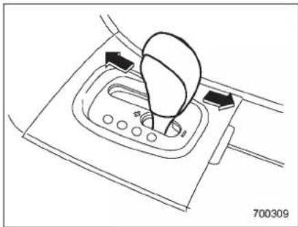
natural_image
Line drawing of a car gear shift lever with no text or symbolsShifttothenext-highergearbybriefly pushingtheselectlevertowardthe“+” endofthemanualgate.
Shifttothenext-lowergearbybriefly pullingtheselectlevertowardthe“-” endofthemanualgate.
NOTE
Pleasereadthefollowingpointscarefullyandbeartheminmindwhenusing themanualmode.
- Whenthetemperatureoftheengine oilishigherthannormal, warning beepsareemittedandtheshiftposition indicatorshows“-”. If these warnings are issued, deselect themanualmode to protect the engine from damage.
- Thetransmissiondoesnotautomaticallyshiftupinthemanualmode. Performgearshiftsinaccordancewith roadconditionssothatthetachometer needledoesnotentertheredzone.If theenginespeedreachesapredeterminedlevel,afuel-cutfunctionwill operate.Shiftupifthishappens.Also, thetransmissionmayautomatically shiftuptoprotecttheengine.
- If you attempt to shift down when the engines speed to high, i.e., when adownshift would push the tachometer needle beyond the red zone, beepswill be emitted to warnyouth at the down-shift is not possible.
- If you attempt to shift up when the vehicles speed distoolow, the transmission will not respond.
- Youcanperformaskip-shift(for example, from4th to2nd) by operating theselectlevertwiceinrapidsuccession.
- Thetransmissionautomaticallyselects1stgearwhenthevehiclestops moving.
- If the temperature of the automatic transmission fluid becomes too high, the "AT OIL TEMP" warning light will illuminate and upshift to 5th gear will not be possible. Immediately stop the vehicle in as safe place and let the engine idle until the warning light turns
off.
■Drivingtips
- Onaroadsurfacewherethereisarisk ofwheelspin(forexample,asnow-or gravel-coveredroad),youcanpullaway fromastandstillsafelyandeasilybyfirst selectingthe2ndgearofthemanual mode.
●Alwaysapplythefootorparkingbrake whenthevehicleisstoppedinthe“D”or “R”position.
●Alwayssettheparkingbrakewhen parkingyourvehicle.Donotholdthe vehiclewithonlythetransmission.
- Donotkeepthevehicleinastationary positiononanuphillgradebyusingthe "D"position.Usethebrakeinstead.
●Theenginemay,onrareoccasions, knock whenthevehicle rapidlyacceleratesorrapidlypullsawayfromastandstill. Thisphenomenondoesnotindicatea problem.
- Aslightreductioninoutputtorquemay occurbeforetheenginewarmsup.
7-18 Starting and operating
■SPORTmode
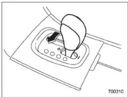
natural_image
Line drawing of a car gear shift lever with a handle and gear (no text or symbols)SPORTmodeisusedwhenpoweris neededforrapidaccelerationorforuphill driving. Toselectthismode, movethe selectleverfromthe"D"positiontothe manualgate.
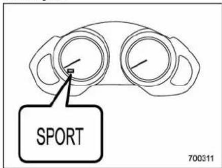
Whenselected, the SPORTmode indicator light on the combination meter will illuminate.
TodeselectSPORTmode, movethe selectlevertothe "D"positionorselect manualmode. Tosubsequently reselect SPORTmode, movetheselectleverto the "D"positionandfromtheretothe manualgate.
Inthismode, the transmission shifts up at higher vehicles speeds and shifts down more responsively than innormal mode.
Powersteering

CAUTION
Donotholdthesteeringwheelatthe fullylockedpositionleftorrightfor morethan5seconds. Thismay damagethepowersteeringpump.
Thepowersteeringsystemoperatesonly whentheengineisrunning. Ifyoulosepowersteeringassistbecause theenginestopsorthesystemfailsto function,youcansteerbutitwilltake muchmoreeffort.
NOTE
Rightaftertheenginehasbeenstarted andbeforeithaswarmedup,youmay hearanoisecomingfromareasadjacenttothepowersteeringpumpwhich islocatedattheright-frontareaofthe enginecompartment.Thisnoiseis normal.Itdoesnotindicatepower steeringsystemtrouble.
Braking
Brakingtips
WARNING
Neverrestyourfootonthebrake pedalwhiledriving. This can cause dangerous overheating of the brakes and need less wear on the brake pads and linings.
▼Whenthebrakesgetwet
Whendrivinginrainorafterwashingthe vehicle,thebrakesmaygetwet.Asa result,brakestoppingdistancewillbe longer.Todrythebrakes,drivethevehicle atasafespeedwhilelightlydepressing thebrakepedaltoheatupthebrakes.
▼Useofenginebraking
Remembertomakeuseofenginebraking inadditiontofootbraking. Whendescendingagrade, ifonlythefootbrakeisused, thebrakesmaystartworkingimproperly because ofbrakefluidoverheating, causedbyoverheatedbrakepads. To helppreventthis, shiftintoalowergearto getstrongerenginebraking.
▼Brakingwhenatireispunctured
Donotdepressthebrakepedalsuddenly whenatireispunctured. This could cause alossofcontrolofthevehicle.Keep drivingstraightaheadwhilegradually reducingspeed.Thenslowlypulloffthe roadtoasafeplace.
Brakesystem
▼Twoseparatecircuits
Your vehicle has a dual circuit brake system. Each circuit works diagonally across the vehicle. Ifone circuit of the brakesystem should fail, the other half of the system still works. Ifone circuit fails, the brake pedal will god down much closer to the floor than usual and you will need to depress it down much harder. And much longer distance will be needed to stop the vehicle.
▼Brakebooster
Thebrakeboosterusesenginemanifold vacuumtoassistbrakingforce.Ifengine manifold vacuum becomes insufficient, suchaswhendrivinginahigh-altitude place,avacuumpumpassuresasufficientvacuumtooperatethebrakebooster.Donotturnofftheenginewhiledriving because thatwillturnoffthebrake booster,resultinginpoorbrakingpower. Thebrakeswillcontinuetoworkeven whenthebrakeboostercompletelystops functioning.Ifthishappens,however,you willhavetodepressthepedalmuch harderthannormalandthebrakingdistancewillincrease.
NOTE
Somesoundaccompanyingoperation of the vacuumpump may be heard from the engine compartment during driving. This does not indicate an malfunction.
▼Brakeassistsystem
WARNING
Donotbeoverconfidentaboutthe brakeassist.Itisnotasystemthat bringsmorebrakingabilitytothe vehiclebeyonditsbrakingcapability.Alwaysusetheutmostcare whendrivingregardingvehicle speedandsafedistance.
CAUTION
When you need to brake suddenly, continued depressing the brake pedal strongly to bring the effect of the brake assist.
NOTE
Whenyoudepressthebrakepedal
-CONTINUED-
7-20 Starting and operating
suddenly, thebrakepedalmightwiggle. Thisisanormaloperationphenomenon, anditisnotamalfunction.
Brakeassistisadriverassistancesystem. Itassiststhebrakepowerwhenthedriver cannotdepressthebrakepedalstrongly andthebrakepowerisinsufficient.
Brakeassistgeneratesthebrakepower accordingtothespeedatwhichthedriver depressesthebrakepedal.
■ Discbrakepadwearwarning indicators
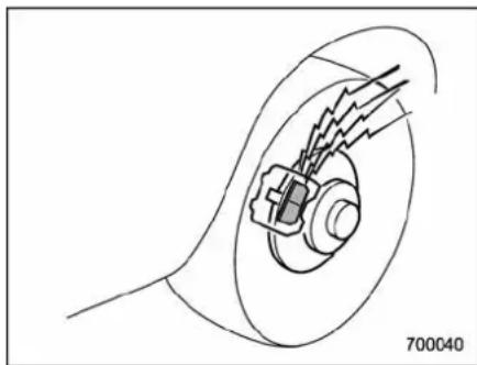
natural_image
Technical line drawing of a mechanical component with internal components and motion lines (no text or symbols)Thediscbrakepadwearwarningindicatorsonthediscbrakesgiveawarning noisewhenthebrakepadsareworn.
Ifasqueakingorscrapingnoiseisheard fromthediscbrakeswhilebraking,im-
mediatelyhaveyourvehicleinspectedby thenearestSUBARUdealer.
ABS(Anti-lockBrakeSystem)

WARNING
Always use the utmost care in driving—overconfidence because you are driving with an ABS equipped vehicle could easily lead to as serious accident.

CAUTION
- TheABSsystemdoesnotalways decreasestoppingdistance.You shouldalwaysmaintainasafe followingdistancefromother vehicles.
- Whendrivingonbadlysurfaced roads, gravelroads, icyroads, or overdeepnewlyfallensnow, stoppingdistancesmaybelongerforavehiclewiththeABS systemthanonewithout.When drivingundertheseconditions, therefore, reduceyourspeedand leaveampledistancefromother vehicles.
- WhenyoufeeltheABSsystem operating,youshouldmaintain
constantbrakepedalpressure. Donotpumpthebrakepedal sincedoingsomaydefeatthe operationoftheABSsystem.
TheABSsystempreventsthelock-upof wheelswhichmayoccurdingsudden brakingorbrakingonslipperyroadsurfaces. Thishelpspreventthelossof steeringcontrolanddirectionalstability causedbywheellock-up.
WhentheABSsystemisoperating, you mayhearachatteringnoiseorfeelaslight vibrationinthebrakepedal. Thisisnormal whentheABSoperates.
TheABSsystemwillnotoperatewhenthe vehiclespeedisbelowapproximately6 mph(10km/h).
■ABSsystemself-check
Youmayfeelaslightshockinthebrake pedalandheartheoperatingsoundof ABSfromtheenginecompartmentjust afterthevehicleisstarted. Thisiscaused byanautomaticfunctionaltestoftheABS systembeingcarriedoutanddoesnot indicateanyabnormalcondition.
■ABSwarninglight
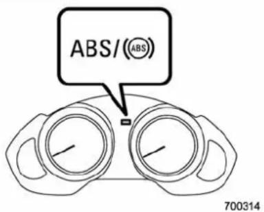
TheABSwarninglightilluminateswhen theignitionswitchisturnedtothe"ON" positionandturnsoffafterapproximately2 seconds.
ThisisanindicationthattheABSsystem isworkingproperly.
CAUTION
If the warning light behaves as follows, the ABS system may not be working properly.
Whenthewarninglightilluminates, theABSfunctionshutsdown; however, theconventionalbrakesystem continuestooperatenormally.
- Thewarninglightdoesnotillu-
minatewhentheignitionswitch isturnedtothe"ON"position.
- The warning light illuminates when the ignitions switch is turned to the "ON" position, but it does not turn off even when the vehicles speed exceeds approximately 8 mph (12 km/h).
- Thewarninglightilluminatesduringdriving.
If these occur, hav the ABS system repaired at the first available opportunity by your SUBARU dealer.
NOTE
If the warning light behavior is described in the following, the ABS system may be considered normal.
- The warning light illuminates right after the engine is started but turn soff immediately, remaining off.
- The warning light remains illuminated after the engine has been started, but it turns off when the vehicles speed reaches approximately 8 mph (12 km/h).
- Thewarninglightilluminatesduring driving,butitturnsoffimmediatelyand remainsoff.
Whendrivingwithaninsufficientbattery
-CONTINUED-
7-22 Starting and operating
voltagesuchaswhentheengineisjump started,theABSwarninglightmayilluminate.Thisisduetothelowbatteryvoltage anddoesnotindicateamalfunction. Whenthebatterybecomesfullycharged, thelightwillturnoff.
ElectronicBrakeForceDistribution(EBD)system
The EBD system maximizes the effectiveness of the brakes by allowing therear brake supply a greater proportion of the braking force. It functions by adjusting the distribution of braking for to therear wheels in accordance with the vehicle's loading condition and speed.
The EBD system is an integral part of the ABS system and uses some of the ABS system's component to perform its function of optimizing the distribution of braking force. If any of the ABS components used by the EBD system malfunction, the EBD system also stops working.
WhentheEBDsystemisoperating, you mayhearachatteringnoiseorfeelaslight vibrationinthebrakepedal. Thisisnormal anddoesnotindicateamalfunction.
■ StepstotakeifEBDsystem malfunctions
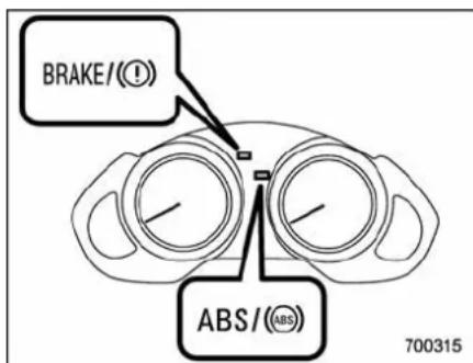
IfamalfunctionoccursintheEBDsystem, thesystemstopsworkingandthebrake systemwarninglightandABSwarning lightilluminatesimultaneously.
The EBD system may be malfunctioning if the brakesystem warning light and ABS warning light illuminates simultaneously during driving.
EveniftheEBDsystemmalfunctions,the conventionalbrakingsystemwillstillfunction.However,therearwheelswillbe morepronetolockingwhenthebrakes areappliedharderthanusualandthe vehicle'smotionmaythereforebecome somewhatardertocontrol. IfthebrakesystemwarninglightandABS
warninglightilluminatesimultaneously, takethefollowingsteps.
- Stopthevehicleinthenearestsafe, flatlocation.
- Shutdowntheengine, apply the parkingbrake, and then restart it.
- Releasetheparkingbrake. If both warninglightsturnoff, the EBD system may bemalfunctioning.
DrivecarefullytothenearestSUBARU dealerandhavethesysteminspected.
4. If both warning lights illuminate again and remain illuminated after the engine has been restarted, shutdown the engine again, apply the parking brake, and check the brake fluid level. Referto "Brakefluid" 11-20.
5. If the brake fluid level is not below the "MIN" mark, the EBD system may be malfunctioning. Drive carefully to the nearest SUBARU dealer and have the system inspected.
6. If the brake fluid level is below the "MIN" mark, DONOT drivethe vehicle. Instead, havethe vehicle towed to the nearest SUBARU dealer for repair.

WARNING
- Drivingwiththebrakesystem warninglightilluminatedisdan-
gerous. This indicates your brake system may not be working properly. If the light remains illuminated, have the brakes inspected by a SUBARU dealer immediately.
- Ifatallindoubtaboutwhether thebrakesareoperatingproperly,donotdrivethevehicle. Haveyourvehicletowedtothe nearestSUBARUdealerforrepair.
VehicleDynamicsControl system

WARNING
Always use the utmost care in driving-overconfidence because you are driving with a Vehicle Dynamics Controlsysteme equipped vehicle could easily lead to serious accident.

CAUTION
- Evenifyourvehicleisequipped withVehicleDynamicsControl system, wintertiresshouldbe usedwhen drivingon snow-coveredoricyroads; in addition, vehiclespeedshouldbereduced considerably. Simplyhavinga VehicleDynamicsControlsystemdoesnotguaranteethatthe vehiclewillbeabletoavoid accidentsinanysituation.
- ActivationoftheVehicleDynamicsControlsystemisan indicationthattheroadbeing travelledonhasaslipperysurface;sincehavingVehicleDynamicsControlisnoguarantee
-CONTINUED-
thatfullvehiclecontrolwillbe maintainedataltimesandunder all conditions,its activation shouldbeseenasasignthat thespeedofthevehicleshould bereducedconsiderably.
- Whenever suspension components, steering components, or anaxleareremovedfrom a vehicleequippedwithVehicle DynamicsControlsystem, have aninspectionofthatsystem performed by a SUBARUdealer.
- The following precautions should be observed in order to ensure that the Vehicle Dynamics Controlsystem is operating properly.
-Allfourwheelsshouldbe fittedwithtiresofthesame size,type,andbrand.Furthermore,theamountofwear shouldbethesameforall fourtires.
-Keepthetire pressure atthe proper level as shown on the vehicleplacardattachedto thedriver'ssidedoorpillar.
In the event of wheelspin and/orskidding on a slippery road surface and/or during
corneringand/oranevasivemaneuver, theVehicleDynamicsControlsystem adjusts the engine's output and the wheels' respective braking forces to help maintaintraction and directional control.
•TractionControlFunction
Thetractioncontrolfunctionisdesignedto preventspinning ofthe drivingwheelson slipperyroadsurfaces,therebyhelping to maintaintraction anddirectional control. Activationofthisfunctionisshownby steady illumination of the Vehicle Dynamics Controloperation indicatorlight.
- SkidSuppressionFunction
Theskidsuppressionfunctionisdesigned tohelpmaintaindirectionalstabilityby suppressingthewheels'tendencytoslide sidewaysduringsteeringoperations.Activationofthisfunctionisshownbyflashing oftheVehicleDynamicsControloperation indicatorlight.
NOTE
- Slighttwitchingofthebrakepedal maybefeltwhentheVehicleDynamics Controlsystemoperates; a smalldegreeofvehicleorsteeringwheelshaking may also be noticed in this situation. These are normal characteristics ofVehicleDynamics Controloperation andarenocauseforalarm.
●Whendriving offimmediatelyafter
startingtheengine,ashortoperation noisemaybenoticedcomingfromthe enginecompartment.Thisnoiseis generatedas aresultofa checkbeing performedontheVehicleDynamics Controlsystemandisnormal. •Depending onthetimingof activa- tionofthebrakes,thebrakepedalmay seemtojoltwhenyoudriveoffafter starting the engine. This is a conse- quence ofthe Vehicle DynamicsCon- troloperationalcheckandisnormal. •In thecircumstanceshowninthe followinglist,thevehiclemaybemore unstablethanitfeelstothedriver.The VehicleDynamicsControlSystemmay thereforeoperate.Suchoperationdoes notindicateasystemmalfunction.
-ongravel-coveredorrutted roads
-onunfinishedroads
-whenthevehicleistowinga trailer
—whenthevehicleisfittedwith snowtiresorwintertires
- Activation of the Vehicle Dynamics Control system will cause operation of the steering wheel to feels slightly different compared to that for normal conditions.
●Evenifthe vehicleisequipped with a Vehicle Dynamics Control system, it
isimportantthatwintertiresbeused whendrivingonsnow-coveredoricy roads.(Allfourwheelsshouldbefitted withtiresofthesamesizeandbrand).
- Itisalwaysimportanttoreduce speedwhenapproachingacorner, evenifthevehicleisequippedwith VehicleDynamicsControl.
- Allfourwheelsshouldbefittedwith tiresofthesamesize,type,andbrand; furthermore,the amount of wear shouldbethesameforallfourtires.If theseprecautionsarenotobserved andnon-matchingtiresareused,itis quitepossiblethattheVehicleDynamicsControlsystemwillbeunable tooperatecorrectlyasintended.
- Alwaysturnofftheenginebefore replacingatireasfailuretodosomay rendertheVehicleDynamicsControl systemunabletooperatecorrectly.
■ VehicleDynamicsControl systemmonitor
▼VehicleDynamicsControloperationindicatorlight
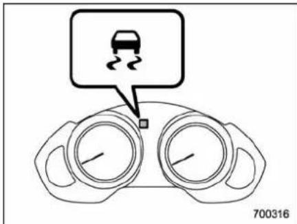
The indicator light illuminates when the ignition key is turned to the ON position; it turns off approximately 2 seconds later. This indicator light flashes during activation of the kids suppression function and is illuminated steadily during activation of the traction control function.
The following two situations could indicate amalfunction of the Vehicle Dynamics Control system; if either should occur, have an authorized SUBARU dealer carry outaninspection of that system at the first available opportunity.
•Theindicatorlightdoesnotilluminate
whentheignitionkeyisturnedtotheON position.
●Theindicatorlightdoesnotturnoff approximately2secondsaftertheignition keyhasbeenturnedtotheONposition.
▼VehicleDynamicsControlwarning light/TractionControlsystemOFF indicatorlight
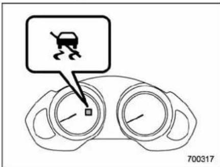
This single lighthast the function of indicating malfunctions in the Vehicle Dynamics Control system and the function of indicating that the Traction Control system is not operating. It illuminates in the event of a malfunction in the system and is illuminated whenever the system is not operating.
▽VehicleDynamicsControlwarning
The warning light illuminates when the ignitions switchisturned to the "ON" position and turn soffseveral seconds after engine startup. This lighting pattern indicates that the Vehicle Dynamics Controlsystem is operating normally.
The following situations could indicate a malfunction of the Vehicle Dynamics Control system; if any should occur, we recommend that you have an authorized SUBARU dealer carry out an inspection of the system at the first available opportunity.
- The warning light does not illuminate when the ignition key is turned to the ON position.
- Thewarninglightilluminateswhilethe vehicleisbeingdriven.
- Whenamalfunctionhasoccurred in the VehicleDynamicsControlelectrical system,onlythewarninglightwillilluminate.Insuchanevent,theABSwillstillbe operatingnormally.
- The warning light will also illuminate when a problem occurs with the ABS or Vehicle Dynamics Controle electronic control systems.
Because the Vehicle Dynamics Control system control seachbrakethrough the ABS, whenever the ABS stops operating
duetoamalfunctioninthatelectrical system,theVehicleDynamicsControlwill alsobecomeunabletocontrolallfour brakes.ThusVehicleDynamicsControl systemoperationhaltsandthewarning lightilluminates.AlthoughboththeVehicle DynamicsControlsystemandtheABS willbeinoperableinthissituation,itwill stillbepossibletostopthevehicleusing normalbraking.TheVehicleDynamics ControlsystemandtheABSdonot adverselyaffectoperationofthevehicle inanywaywhentheyareinoperable; howevershouldsuchasituationoccur, drivewithcareandhaveanauthorized SUBARUdealercarryoutaninspection of thoseystemsatthefirstavailableopportunity.
NOTE
Whenthewarninglightilluminatesand turnsoffinthefollowingway,itindicates that the VehicleDynamics Controlsystemisoperatingnormally.
- Althoughilluminatingaftertheenginehasbeenstarted,thewarninglight quicklyturnsoffandremainsoff. - Thewarninglightilluminateswhen thevehicleisbeingdriven;itthenturns offandremainsoff.
TractionControlsystemOFFindicatorlight
Thislightilluminatestoindicatethatthe TractionControlsystemisinnon-operationmode. Thisdoesnotconstitutefailure oftheVehicleDynamicsControlsystem.
NOTE
- The indicator light may remain illuminated for awhile after the engine has been started, especially in cold weather. This occurs because the engine has not yet warmed up and is completely normal. The light will turn off when the engine has reached suitable operating temperature.
- When an engine problem occurs andthemalfunctionindicatorlamp illuminates, the indicatorlightwill also illuminate.
The following two situations could indicate malfunction of the Vehicle Dynamics Control system; if either should occur, have an authorized SUBARU dealer carry outan inspection of that system at the first available opportunity.
●Theindicatorlightdoesnotilluminate whentheignitionkeyisturnedtotheON position. - The indicator light fail to turn off after the engine is started, even when several minutes have passed to allow the engine
toheatupsufficiently.
■TractionControlsystemOFF switch
Pressing the switch TractionControl system can facilitate the following operations.
- astandingstartonasteeeplysloping roadwithasnowy,gravel-covered,or otherwiseslippery surface
●extricationofthevehiclewhenits wheelsarestuckinmudordeepsnow
Whentheswitchispressedduringengine operation,theTractionControlsystem OFFindicatorlight" 🔍"onthecombination meterilluminates.TheTractionControl systemwillbedeactivatedandthevehicle willbehavelikeamodelnotequippedwith
theTractionControlsystem.Whenthe switchispressedagaintoreactivatethe TractionControlsystemOFFindicator light" "turnsoff.
With the TractionControlsystemdeactivated, tractionenhancementoffered by TractionControlsystemisunavailable. Therefore you should not deactivate the TractionControlsystemexceptunder above-mentioned situations.
NOTE
- Whentheswitchhasbeenpressed todeactivatetheTractionControlsystem,theTractionControlsystemautomaticallyreactivatesitselfthe next time the ignition key is turned to the "LOCK" positionandtheengineisrestarted. - Itheswitchishelddownfor10 secondsorlonger,theindicatorlight turnsoff,theTractionControlsystem isactivated,andthesystemignores anyfurtherpressingoftheswitch.To maketheswitchusableagain,turnthe ignition key to the "LOCK" position and restarttheengine.
- Whentheswitch ispressed to deactivate the TractionControl system, the vehicle's running performance is comparable with that of a vehicle that does not have a Traction Control system. Donotdeactivate the Traction
Controlsystem exceptwhen absolutely necessary.
Tirepressuremonitoring system(TPMS)
Thetirepressuremonitoringsystempro-videsthedriverwithawarningmessage bysendingasignalfromasensorthatis installedineachwheelwhentirepressure isseverelylow.
Thetirepressuremonitoringsystemwill activateonlywhenthevehicleisdrivenat speedsabove20mph(32km/h).Also, thissystemmaynotreactimmediatelytoa suddendropintirepressure(forexample, ablow-outcausedbyrunningovera sharpobject).

WARNING
Ifthelowtirepressurewarninglight illuminateswhiledriving,never brakesuddenlyandkeepdriving straightaheadwhilegraduallyredu-cingspeed.Thenslowlypulloffthe roadtoasafeplace.Otherwisean accidentinvolvingseriousvehicle damageandseriouspersonalinjury couldoccur.
Check the pressure for all four tires and adjust the pressure to the cold tire pressures shown on the tire placard on the door pillar on the driver's side.
Evenwhenthevehicleisdrivena veryshortdistance, the tires get warmandtheirpressuresincrease accordingly. Besuretoletthetires coolthoroughlybeforeadjusting theirpressurestothestandard valuesshownonthetireplacard. Referto“Tiresandwheels” 11-24. Thetirepressuremonitoringsystem doesnotfunctionwhenthevehicle isstationary. Afteradjustingthetire pressures, increasethevehicle speedtoatleast20mph(32km/h) tostarttheTPMSre-checkingofthe tireinflationpressures. Ifthetire pressuresarenowabovethesevere
lowpressurethreshold,thelowtire pressurewarninglightshouldturn offafewminuteslater.
If thislightstillilluminateswhile drivingafteradjustingthetirepressure,atiremayhavesignificant damageandafastleakthatcauses thetiretoloseairrapidly.Ifyouhave aflattire,replaceitwithasparetire assoonaspossible.
Whenasparetireismountedora wheelrimisreplacedwithoutthe originalpressuresensor/transmitter beingtransferred,thelowtirepressurewarning lightwillilluminate steadilyafterblinkingforapproximatelyoneminute.Thisindicates theTPMSisunabletomonitorall fourroadwheels.Contactyour SUBARUdealerassoonaspossible fortireandsensorreplacementand/orsystemresetting.
Donotinjectanytireliquidor aerosoltiresealantintothetires, asthismaycauseamalfunction of the tirepressuresensors. If the light illuminates steadily after blinking for approximately on minute, promptly contacta SUBARU deal to have the system inspected.

CAUTION
Donotplacemetalfilmoranymetal partsunderthedriver'sseat. This may cause poor reception of the signals from the tire pressures sensors, and the tire pressure monitoringsystem will not function properly.
NOTE
This device complies with Part 15 of the FCC Rules and with RSS-210 of Industry Canada. Operation is subject to the following two conditions: (1) This device may not cause harmful interference, and (2) this device must accept any interference received, including interference that may cause undesired operation.
Changes or modifications not expressly approved by the party responsible for compliance could void the user's authority to operate the equipment.
Parkingyourvehicle

WARNING
- Neverleaveunattendedchildren orpetsinthevehicle. They could accidentally injurethemselvesor othersthroughinadvertentoperationofthevehicle. Also, on hotorsunnydays, the temperature inaclosedvehicle could quickly become highenoughto causes evereorpossibly fatal injuriesto them.
- Donotparkthevehicleover flammablematerialssuchasdry grass, wastepaperorrags, as theymayburn easily iftheycome nearhotengineorexhaustsystem parts.
- Be sure to stop the engine if you takeanapinthevehicle.If engineexhaustgasentersthe passengercompartment,occupantsinthevehiclecoulddie fromcarbon monoxide(CO) contained in theexhaust gas.

Parkingbrake

CAUTION
●Neverdrivewhiletheparking brakeissetbecausethiswill causeunnecessarywearonthe brakelinings.Beforestartingto drive,alwaysmakesurethatthe parkingbrakehasbeenfully released.
- Never drive with your foot on the parking brakepedal.
Tosettheparkingbrake,holddownthe brakepedalwhiledepressingtheparking brake pedal as far as it will go.
natural_image
Diagram of a hand holding a small mechanical component with motion lines indicating movement (no text or symbols)Toreleasetheparkingbrake,holddown thebrakepedalwhiledepressingthe parkingbrakepedalandslowlyreleasing it.
Whentheparkingbrakeissetwhilethe engineisrunning,thebrakesystem warninglightilluminates.Afterstarting thevehicle,besurethatthewarninglight hasturnedoffbeforethevehicleisdriven. Referto"Brakesystemwarninglight" 3-16.
Parkingtips
Whenparkingyourvehicle,alwayssetthe parkingbrakefirmlyandputtheselect leverinthe"P"(Park)position.Alwaysset theparkingbrakefirmlywhenparkingyour vehicle.Neverrelyonthetransmission alonetoholdthevehicle.
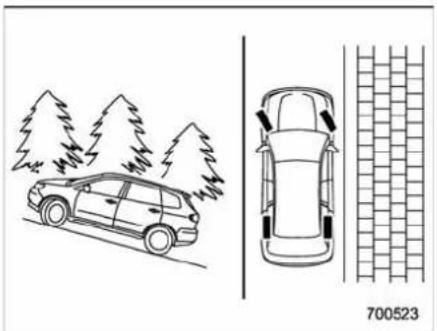
natural_image
Top-down line drawing of a car with trees and a side view showing front and rear views (no text or symbols)Whenparkingonahill, alwaysturnthe steeringwheel. Whenthevehicleis headedupthehill, thefrontwheelsshould be turnedawayfromthecurb.
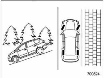
natural_image
Top-down line drawing of a car with trees and a side view showing a brick wall (no text or symbols)Whenfacingdownhill, thefrontwheels should be turned into the curb.
Cruisecontrol
Cruisecontrolenablesyoutomaintaina constantvehiclespeedwithoutholding yourfootontheacceleratorpedalanditis operativewhenthevehiclespeedis25 mph(40km/h)ormore.Makesurethe mainswitchisturned"OFF"whenthe cruisecontrolisnotinusetoavoid unintentionallysettingthecruisecontrol.
NOTE
If you mov the cruise control lever or pressthemains switch button while turning the ignition switch "ON", the cruise control function is deactivated and the cruise control indicator light flashes. Toreactivatethe cruise control function, turn the ignition switch back to the "Acc" or "LOCK" position, and then turn it again to the "ON" position.

WARNING
Donotusethecruisecontrolunder anyofthefollowingconditions.This maycauselossofvehiclecontrol:
- drivingupordownasteepgrade
- drivingonslipperyorwinding roads
- drivinginheavytraffic
■ Tosetcruisecontrol
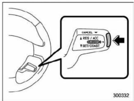
- Pushthemainswitchbutton.
Thecruisecontrolindicatorlightonthe combinationmeterwillilluminate.
2. Depresstheacceleratorpedaluntilthe
vehiclereachesthedesiredspeed.
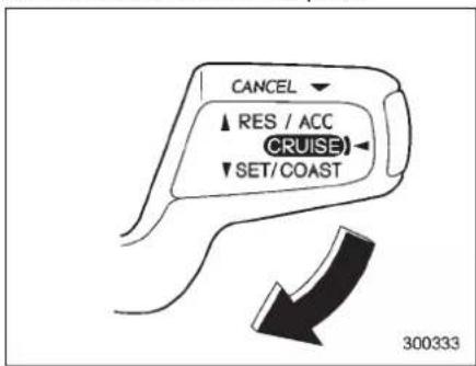
- Push the control lever downward in the "SET/COAST" direction and release it. Then releasethe accelerator pedal.
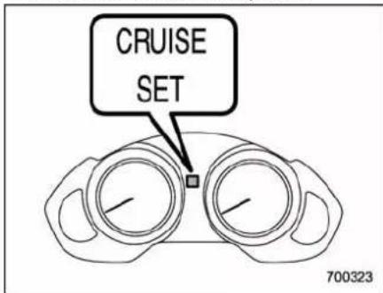
Atthistime, thecruisecontrolsetindicator lightisilluminatedonthecombination
meter.
The vehicle will maintain the desired speed.
Vehiclespeedcanbetemporarilyincreasedwhiledrivingwiththecruise controlactivated.Simplydepressthe acceleratorpedaltoacceleratethevehicle.Whentheacceleratorpedalisreleased,thevehiclewillreturntoand maintainthepreviouscruisingspeed.
■ Totemporarilycancelthe cruisecontrol
Therearethreewaystocancelthecruise controltemporarily:
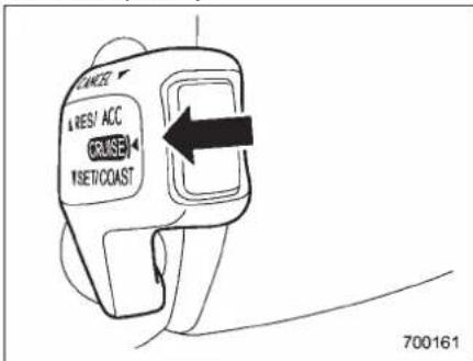
• Pullthecontrollevertowardyou.
• Depressthebrakepedal.
- Shift the select lever into the "N"
-CONTINUED-
position.
The cruisecontrolsetindicatorlightonthe combinationmeterturnsoffwhenthe cruisecontroliscanceled.
Toresumethecruisecontrol after ithas been temporarily canceled and with vehiclespeed of approximately 20 mph (32 km/h) or more, push the control lever upward in the "RES/ACC" direction to return to the original cruising speed automatically.
Thecruisecontrolsetindicatorlightonthe combinationmeterwillautomaticallyilluminateatthistime.
■ Toturnoffthecruisecontrol
Therearetwowaystoturnoffthecruise control:
- Pushthemainswitchagain.
- Turn the ignition switch to the "Acc" or "LOCK" position (but only when the vehicle is completely stopped).
■ Tochangethecruisingspeed
▼Toincreasethespeed(bycontrol lever)
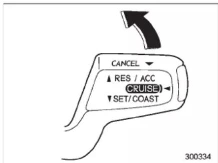
Push the control lever upward in the "RES/ACC" direction and hold it until the vehicle reach the desired speed. Then, release the controller. The vehicles speed at that moment will be memorized and treated as thenewsets speed.
Whenthedifferencebetweentheactual vehiclespeedandthe setspeedisless than4mph(6.8km/h),thesetspeedcan beincreased1mph(1.6km/h)eachtime bypassingthecontrolleverupwardinthe "RES/ACC"directionquickly.
▼Toincreasethespeed(byacceleratorpedal)
- Depresstheacceleratorpedalto acceleratethevehicletothedesired speed.
- Pushthecontrollever downwardinthe "SET/COAST" directiononce.Nowthe desiredspeedissetandthevehiclewill keeprunningatthat speed without depressingtheacceleratorpedal.
NOTE
If the difference between the actual vehiclespeed when the control lever is pushdownward and the speed last timeyousetis less than 4 mph (6.8 km/h), the vehicle speed will be lowered by 1 mph (1.6 km/h). This occurs because the cruise control system unit regard this lever operation that intended to decrease the vehicle speed.
▼Todecreasethespeed(bycontrol lever)
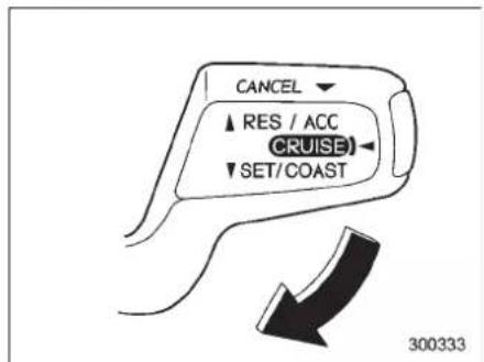
Pushthecontrolleverdownwardinthe "SET/COAST" directionandholdituntil thevehiclereachesthedesiredspeed. Then, releasethecontrollever. The vehiclespeedatthatmomentwillbe memorizedandtreatedasthenewset speed.
Whenthedifferencebetweentheactual vehiclespeedandthesetspeedisless than4mph(6.8km/h),thesetspeedcan belowered1mph(1.6km/h)eachtimeby pressingthecontrolleverdownwardinthe "SET/COAST"directionquickly.
▼Todecreasethespeed(bybrake pedal)
- Depressthebrakepedaltorelease cruisecontroltemporarily.
- Whenthespeeddecreasestothe desiredspeed, pressthecontrollever downwardinthe"SET/COAST"direction once. Nowthedesiredspeedissetand the vehicle will keep running at that speed without depressing the accelerator pedal.
Cruisecontrolindicatorlight
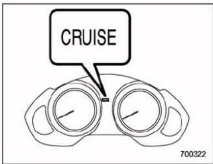
Thecruisecontrolindicatorlightilluminateswhentheignitionswitchisturnedto the "ON" position and turns off after approximately3seconds. Thelightilluminateswhenthe"CRUISE" mainswitchispressed.
If you move the cruise control lever while turningtheignitionswitch"ON", thecruise controlfunctionisdeactivatedandthe cruisecontrolindicatorlightflashes.To reactivatethe cruisecontrolfunction, turn theignitionswitchbacktothe"Acc"or "LOCK"position,and thenturnitagainto the"ON"position.
■Cruisecontrolsetindicator light
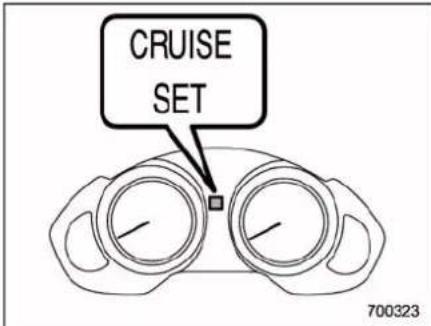
Thecruisecontrolsetindicatorlight illuminateswhentheignitionswitchis turnedtothe"ON"positionandturnsoff afterapproximately3seconds. Thelightilluminateswhenvehiclespeed hasbeenset.
| -1.5 | -1.5 | -1.5 | -1.5 |
Driving tips
Newvehiclebreak-indriving-thefirst
1,000miles(1,600km)......8-2
Fueleconomyhints....8-2
Engineexhaustgas(carbonmonoxide)......8-2
Catalyticconverter....8-3
Periodicinspections....8-4
Drivinginforeigncountries....8-4
DrivingtipsforAWDmodels....8-4
On-pavementandoffroaddriving....8-5
Winterdriving....8-7
Operationduringcoldweather....8-7
Drivingonsnowyandicyroads....8-9
Corrosionprotection....8-10
Snowtires....8-10
Tirechains....8-11
Rockingthevehicle....8-11
Loadingyourvehicle.... 8-11
Vehiclecapacityweight.... 8-12
GVWRandGAWR(GrossVehicleWeightRating andGrossAxleWeightRating)...... 8-12
Roofrailsandcrossbar(ifequipped).... 8-13
Roofmoldingandcrossbar(ifequipped).... 8-16
Trailerhitch(ifequipped)....8-18
Connecting a trailer .... 8-18
Whenyoudonottowatrailer.... 8-20
Trailertowing....8-20
Warranties and maintenance.... 8-20
Maximumloadlimits 8-20
Trailer hitches.... 8-23
Connecting a trailer 8-24
Trailer towing tips 8-26
8-2Drivingtips
Newvehiclebreak-indriving – the first 1,000 miles (1,600 km)
The performance and long life of your vehicle are dependent on how you handle and care for your vehicle while it is new. Follow these instructions during the first 1,000 miles (1,600 km):
- Donotracetheengine.Anddonot allowenginespeedtoexceed4,000rpm exceptinanemergency.
- Donotdriveatoneconstantengineor vehiclespeedforalongtime, either fastor slow.
- Avoidstartingsuddenlyandrapid acceleration,exceptinanemergency.
- Avoid hard braking, except in an emergency.
Thesamebreak-inproceduresshouldbe appliedtoanewlyinstalledoroverhauled engineorwhenbrakepadsorbrake liningsarereplacedwithnewones.
Fueleconomyhints
The following suggestions will help to save yourfuel.
- Select the proper gear position for the speed and road conditions.
- Avoidsuddenaccelerationordeceleration. Alwaysaccelerategentlyuntilyou reachthedesiredspeed. Thentryto maintainthatspeedfor aslongas possible.
- Donotpumptheacceleratorandavoid racingtheengine.
●Avoidunnecessaryengineidling. - Keeptheengineproperlytuned.
- Keepthetiresinflatedtothecorrect pressureshownonthetireplacard,which islocatedunderthedoorlatchonthe driver'sside.Lowpressurewillincrease tirewearandfuelconsumption.
- Usetheair conditioner onlywhen necessary.
- Keep the frontandrearwheelsin properalignment.
- Avoidcarryingunnecessaryluggageor cargo.
Engineexhaustgas(carbon monoxide)

WARNING
- Neverinhaleengineexhaustgas. Engineexhaustgas contains carbonmonoxide, acolorless and odorless gas which is dangerous, orevenlethal, ifinhaled.
●Alwaysproperlymaintaintheengineexhaustsystemtoprevent engineexhaustgasfromenteringthevehicle. - Neverruntheengineinaclosed space, such as agarage, except for the brief time needed to drive the vehicle in or out of it.
- Avoidremaininginaparked vehicleforalengthytimewhile theengineisrunning.lfthatis unavoidable,thenusetheventilationfantoforcefreshairinto thevehicle.
●Alwayskeepthefrontventilator inletgrillefreefromsnow,leaves orotherobstructionstoensure thattheventilationsystemalwaysworksproperly.
•Ifatanytimeyoususpectthat
exhaustfumesareenteringthe vehicle, have the problem checkedandcorrectedassoon aspossible.Ifyoumustdrive undertheseconditions,drive onlywithallwindowsfullyopen.
- Keepthereargateclosedwhile drivingtopreventexhaustgas fromenteringthevehicle.
NOTE
Duetothexpansionandcontraction ofthemetalsusedinthemanufacture oftheexhaustsystem,youmayheara cracklingsoundcomingfromtheexhaustsystemforashorttimeafterthe enginehasbeenshutoff.Thissoundis normal.
Catalyticconverter

WARNING
- Avoidfirehazards.Donotdrive orparkthevehicleanywhere near flammable materials (e.g. grass,paper,ragsorleaves), becausethecatalyticconverter operatesatveryhighttemperatures.
- Keepeveryoneandflammable materialsawayfromtheexhaust pipewhiletheengineisrunning. Theexhaustgasisveryhot.
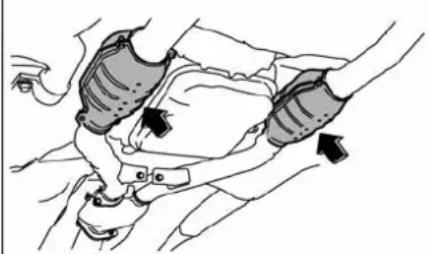
natural_image
Line drawing of a car seatbelt with hands adjusting the seat (no text or symbols)800392
The catalytic converter is installed in the exhaust system. Its serves as catalyst to
reduceHC, CO and NOxin exhaust gases, thus providing cleaner exhaust.
Toavoiddamagetothecatalyticconverter:
- Useonlyunleadedgasoline.Evena smallamountofleadedgasolinewill damagethecatalyticconverter.
- Neverstarttheenginebypushingor pullingthevehicle.
- Avoidracingtheengine.
- Neverturnofftheignitionswitchwhile thevehicleismoving.
- Keepyourenginetuned-up. If you feel the engineer running rough (misfiring, back-firing or incomplete combustion), have your vehicle checked and repaired by an authorized SUBARU dealer.
- Donotapplyundercoatingorrust preventiontreatmenttotheheatshieldof catalyticconverterandtheexhaustsystem.
- Donotdrivewithanextremelylowfuel level.
8-4Drivingtips
Periodicinspections
Tokeep your vehicle in the best condition at all times, always havethere recommended maintenance services listed in themaintenanceschedule in the "Warranty and Maintenance Booklet" performed at the specified time or mileage intervals.
Drivinginforeigncountries
Whenplanningtouseyourvehiclein anothercountry:
- Confirmtheavailabilityofthecorrect fuel.Referto“Fuelrequirements” ^7-2 .
- Complywithallregulationsandre- quirementsofeachcountry.
DrivingtipsforAWDmodels

WARNING
●Alwaysmaintainasafedriving speedaccordingtotheroadand weatherconditionsinorderto avoidhavinganaccidentona sharpturn,during sudden brakingorunderothersimilarconditions.
●Alwaysusetheutmostcarein driving—overconfidencebecauseyouaredrivinganAll-WheelDrivemodelcouldeasily leadtoaseriousaccident.
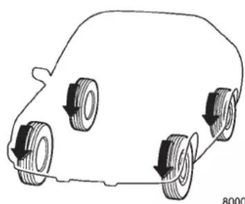
natural_image
Simple line drawing of a car with four wheels and arrows indicating clockwise motion (no text or symbols)All-Wheel Drived distributesthe engine
powertoallfourwheels.AWDmodels providebettertractionwhendrivingon slippery,wetorsnow-coveredroadsand whenmovingoutofmud,dirtandsand. Byshiftingpowerbetweenhefrontand rearwheels,SUBARUAWDcanalso provideaddedtractionduringacceleration,andaddedenginebrakingforce duringdeceleration.
Therefore, your SUBARUAWD vehicle may handled differently than an ordinary twowheeldrive vehicle and it contains some features uniqueto AWD. Forsafety purposes as well as to avoid damaging the AWD system, you should keep the following tips in mind.
●AnAWDmodelisbetterabletoclimb steeperroadsundersnowyorslippery conditionsthanatwowheeldrivevehicle. Thereislittledifferenceinhandling, however,duringextremelysharpturnsor suddenbraking.Therefore,whendriving downaslopeorturningcomers,besure toreduceyourspeedandmaintainan ampledistancefromothervehicles.
- Whenreplacingatire,makesureyou useonlythesamesize,circumference, construction,brand,andloadrangeasthe originaltireslistedonthetireplacard. Usingothersizes,circumferencesor constructionmayresultinseveremechanicaldamagetothedrivetrainofyour
vehicleandmayaffectride, handling, braking, speedometer/odometercalibration, and clearance between the body and tires. It also may be dangerous and lead to loss of vehicle control.
- If you use atemporary spare tire to replace a flattire, besuretousethe original temporary spare tire restored in the vehicle. Using others sizes may result in severe mechanical damage to the drive train of your vehicle.
●Alwayscheckthecoldtirepressure beforestarting todrive. Therecommended tirepressure is provided on the tireplacard, which is located under the doorlatchonthedriver's side.
- Therearesomeprecautionsthatyou mustobservewhentowingyourvehicle. Fordetailedinformation,referto“Towing” 9-14.
On-pavementandoffroad driving

WARNING
●Inarollovercrash, an unbelted person is significantly more likely to die than a person wearingaseatbelt. Youthedriver and allyourpassengers should fastentheseatbeltsbeforestarting to drive in order to minimize the chance of serious injury or death.
- Donotmakesharpturnsand quickmaneuversunlessabsolutely unavoidable. Suchactions aredangerousasyoumaylose control,possiblyresultingina rolloverwhichcouldcauseddeath orseriousinjury.
●Alwaysmaintainasafedriving speedaccordingtothe roadand weatherconditionsinorderto avoidhavinganaccidentona sharpturn,duringsuddenbrakingor under othersimilar conditions.
- Wheneverstrongcrosswindsare present,slowdownsufficiently to maintaincontrol of your vehicle.Rememberthatyourvehicle,
-CONTINUED-
8-6Drivingtips
withitshigherprofileandcenter ofgravity,ismorelikelytobe affectedbycrosswindsthanordinarypassengercars.
●Alwaysusetheutmostcarein driving—overconfidence becauseyouaredrivinganAll-WheelDrivemodelcouldeasily leadtoaseriousaccident.
Yourvehicleisclassifiedasutility vehicle. Utilityvehiclesfeatureahigher groundclearancewhichenablesthemto beusedforwideapplicationsincludingoff-road driving. But please keep in mind that yourvehicleisneitheraconventionaloff-roadvehiclenoranall-terrainvehicle.A higher center of gravity in relation to the treadwidth ascompared withordinary passengercarsmakesvehiclesof this typemorelikelytorollover.Inreality,utility vehicleshaveasignificantlyhigherroll-overratethanothertypesofvehicles.The high groundclearanceofthisvehicleisa realadvantage,givingyouabetterviewof theroadandallowingyoutoanticipate problemsearlier.However,rememberthat yourutilityvehicleisnotdesignedforhigh-speedcorneringcomparabletoordinary passengercarsandthatyourvehicle could roll over if you make a sharp turn athighspeed.Ifyoudototakeyour
SUBARUoff-road, certain common sense precaution such as those in the following list should be taken.
- Make certain that you and all of your passengers are wearing seatbelts.
- Carry some emergency equipment, such as a towing rope or chain, a shovel, wheelblocks, first aid kit and cellphone or citizens band radio.
- Drive carefully. Donottakeunnecessary risks by driving in dangerous areas or over rough terrain.
- Slowdownandemployextrac cautionat all times. When driving off-road, you will nothave thebenefitof markedtraffic lanes,bankedcurves,trafficsignsand the like.
- Donotdrive acrosssteepslopes. Instead, drive either straight up or straight down the slopes. A vehicle can much moreeasilytipoversidewaysthanitcan end over end. Avoid driving straight up or down slopes that are too steep.
- Avoidsharpturningmaneuvers,especially at higher speeds.
- Do not grip the inside or spokes of the steeringwheel. Abadbumpcouldjerkthe wheelandinjureyourhands. Insteaddrive withyourfingers andthumbson the outside of the rim.
- If drivingthrough water,suchaswhen
crossingshallow streams, first check the depth of the water and the bottom of the stream bed for firmness and ensure that the bed of the stream is flat. Driveslowly and completely through the stream. The waters should be shallow enough that it does not reach the vehicle's undercarriage. Water entering the engine air intake or the exhaust pipe or waters plashing onto electrical parts may damage your vehicle and may cause it to stall. Never attempt to drivethrough rushing water; regardless of its depth, it can wash away the ground from underyour tires, resulting in possible loss of traction and even vehicle rollover.
●Alwayscheckyourbrakesforeffectivenessimmediatelyafterdrivinginsand, mudorwater.Dothisbydrivingslowly andsteppingonthe brakepedal. Repeat thatprocessseveraltimestodryoutthe brake discs and brakepads.
- Do not drive or park over or near flammable materials such as dry grass or fallenleaves, astheymayburneasily. The exhaust system is very hot while the engineisrunningandrightafterengine stops. This could create a fire hazard.
●Afterdrivingthroughtallgrass,mud, rocks,sand,rivers,etc.,checkthatthere isnograss,bush,paper,rags,stones, sand, etc. adhering to or trapped on the
underbody.Clearoffanysuchmatterfrom theunderbody.Ifthevehicleisusedwith thesematerialstrappedoradheringtothe underbody,amechanicalbreakdownor firecouldoccur.
- Secureallcargocarriedinsidethe vehicleandmakecertainthatitisnot piledhigherthantheseatbacks.During suddenstopsorjolts,unsecuredcargo couldbethrownaroundinthevehicleand causeinjury.Donotpileheavyloadson thereof.Thoseloadsraisethevehicle's centerofgravityandmakeitmoreprone totipover.
- If you must rock the vehicle to free it froms and from mud, depress the accelerator, pedals slightly and movetheselect lever back and forth between "D" and "R" repeatedly. Donotracethe engine. For the best possible traction, avoid spinning the wheels when trying to free the vehicle.
- Whentheroadsurfaceisextremely slippery,youcanobtainbettertractionby startingthevehiclewiththetransmission in2ndthan1st.
●Neverequipyourvehiclewithtires largerthanthosespecifiedinthismanual. - Washthevehicle'sunderbodyafteroff-roaddriving.Suspensioncomponentsare particularlypronetodirtbuildup,sothey needtobewashedthoroughly.
●FrequentdrivingofanAWDmodel
underhard-drivingconditionssuchas roughroadsoroffroadswillnecessitate morefrequentreplacementofengineoil, brakefluidandtransmissionoilthanthat specifiedinthemaintenanceschedule describedinthe"WarrantyandMaintenanceBooklet".
Remember that damaged on to your SUBARU while operating it off-road and not using commonsense precautions such as those listed above is not eligible for warranty coverage.
Winterdriving
natural_image
Line drawing of a snowman driving on a snowy mountain road (no text or symbols)■Operationduringcold weather
Carrysomeemergencyequipment,such asawindowscraper,abagofsand, flares,asmallshovelandjumpercables.
Check the battery and cables. Cold temperatures reduce battery capacity. The battery must being good condition to provide enough power for cold winter starts.
Useanengineoilofpropergrade and viscosity for cold weather. Heavysummer oil will cause harder starting.
Keepthedoorlocksfromfreezingby squirtingthemwithdeicerorglycerin.
-CONTINUED-
8-8Drivingtips
Forcingafrozendooropenmaydamage orseparatetherubberweatherstrips aroundthedoor.lfthedoorisfrozen, usehotwatertomelttheice,andafterwardsthoroughlywipethewateraway.
Useawindshieldwasherfluidthatcontainsanantifreezesolution.Donotuse engineantifreezeorothersubstitutes because they may damage the paint of the vehicle.
SUBARUWindshieldWasherFluidcontains58.5%methylalcoholand41.5% surfactant,byvolume.ltsfreezingtemperaturevariesaccordingtohowmuchit isdiluted,asindicatedinthefollowing table.
| WasherFluidConcentration | FreezingTemperature |
| 30% | 10.4°F (-12°C) |
| 50% | -4°F (-20°C) |
| 100% | -49°F (-45°C) |
Inordertopreventfreezingofwasher fluid, checkthefreezingtemperaturesin thetableabovewhenadjustingthefluid concentrationtotheoutsidetemperature.
If you fill the reservoir tank with a fluid with adifferent concentration from the one used previously, purgetheoldfluid from the piping between the reservoir tank and
washernozzlesbyoperatingthewasher foracertainperiodoftime. Otherwise,if theconcentrationofthefluidremaininging in thepipingis toolowfortheoutside temperature,itmayfreezeandblockthe nozzles.
CAUTION
- Adjustthewasherfluidconcentrationappropriatelyfortheoutsidetemperature.Iftheconcentrationisinappropriate,sprayed washerfluidmayfreezeonthe windshield andobstructyour view,andthefluidmayfreezein thereservoirtank.
- State or local regulations on volatileorganiccompoundsmay restricttheuseofmethanol,a commonwindshieldwasheranti-freezeadditive.Washerfluids containingnon-methanolanti-freeze agents should be used only if they provide cold weather protection without damaging your vehicle's paint, wiper blades or washersystem.
▼ Beforedrivingyourvehicle
Beforeenteringthevehicle,removeany snoworicefromyourshoesbecause that
couldmakethepedalsslippery and drivingdangerous.
While warming up the vehicle before driving, check that the accelerator pedal, brake pedal, and all other controls operate smoothly.
Clearaway ice and snow that has accumulated under the fender to avoid making steering difficult. During severe winter driving, stop when and where it is safe to do so and check under the fenders periodically.
▼ Parkingincoldweather
WARNING
Snowcantrapdangerousexhaust gasesunderyourvehicle.Keep snowclearoftheexhaustpipe and from around your vehicle if you park the vehicle in snow with the engine running.
Do notusetheparkingbrakewhen parkingforlongperiodsincoldweather since it could freeze in that position. Instead, you should observ the following tips.
- Placetheselectleverin "P" position.
- Usetirestopsunder the tiresto preventthevehiclefrommoving.
Whenthevehicleisparkedinsnowor whenitsnows,raisethewiperbladesoff theglasstoppreventdamagetothem.
Whenthevehiclehasbeenleftparked afteruseonroadsheavilycoveredwith snow,orhasbeenleftparkedduringa snowstorm,icingmaydeveloponthe brakesystem,whichcouldcausepoor brakingaction.Checkforsnoworice builduponthesuspension,discbrakes andbrakehosesunderneaththevehicle.
If there is caked snow orice, remove it, being careful not to damagethedisc brakes and brake hoses and AB Sharness.
▼Refuelingincoldweather
Tohelppreventmoisturefromformingin thefuelsystemandtheriskofitsfreezing, useofanantifreezeadditiveinthefuel tankisrecommendedduringcoldweather. Useonlyadditivesthatarespecifically designedforthispurpose.Whenan antifreezeadditiveisused,itseffectlasts longerifthetankisrefilledwheneverthe fuellevelreacheshalfempty.
If your SUBARU is not going to be used for an extended period, it is best to have the fuel tank filled to capacity.
■Drivingonsnowyandicy roads

WARNING
Donotusethecruisecontrol on slipperyroadssuchassnowyoricy roads. This may cause loss of vehicle control.

CAUTION
Avoidprolongedcontinuousdriving insnowstorms.Snowwillenterthe engine's intake system and may hindertheairflow,whichcouldresultinengineshutdownoreven breakdown.
Topreventskiddingandslipping, avoid suddenbraking, abruptacceleration, high-speeddriving, and sharpturning when driving on snowy or icy roads.
Always maintain a n am pledistance between your vehicle and the vehicle ahead of you to avoid theneed for sudden braking.
Tosupplementthefootbrake, usethe enginebrakeeffectively to control the vehiclespeed. (Shift into a lower gear when necessary.)
Avoidshiftingdownabruptly.Suchbeha-
viorcancausethewheelstolock,possibly leading to lossof vehicle control. An anti-lockbrakesystem(ABS)enhances your vehicle's braking performance on snowy and icy roads. For information about braking on slippery surfaces, referto "ABS(Anti-lock Brake System)" 7-20 and "Vehicle Dynamics Control system" 7-23.
▼Wiperoperationwhensnowing
Beforedrivingincoldweather,makesure thewiperbladesarenotfrozentothewindshieldorrearwindow.Ifthewiper bladesarefrozentothewindshieldorrear window,usethedefrosterwiththeairflow controlbuttoninthe" ”positionandthe temperaturecontroldialsetformaximum warmthuntilthewiperbladesarecompletelythawedout.Thwiperdeiceris helpfultothawthewindshieldwiper blades.Tothawouttherearwiperblade, usetherearwindowdefogger.
Whendrivinginsnow,iffrozensnowstarts tostickonthesurfaceofthewindshield despitewiperoperation,usethedefroster withtheairflowcontrolbuttonin" and thetemperaturecontroldialsetformax-imumwarmth. Afterthewindshieldgets warmedenoughtomeltthefrozensnow onit, washitawayusingthewindshield washer.
-CONTINUED-
8-10 Drivingtips
Snowstuckonthewiperarmpreventsthe wiperfromworkingeffectively.Ifsnowis stuckonthewiperarm,pullofftheroadto asafeplace,thenremoveit.Ifyoustop thevehicleatroadside,usethehazard warningflashertoalertotherdrivers.
Werecommenduseofnon-freezingtype wiperblades(winterblades)duringthe seasonsinwhichyoucouldhavesnow andfreezingtemperatures.Bladesofthis typegivesuperiorwipingperformancein snowyconditions.Besuretouseblades thataresuitableforyourvehicle.

CAUTION
During high-speed driving, non-freezing typewiper blades may not perform as well as standard wiper blades. If this happens, reduce the vehicle speed.
NOTE
When these season requiring non-freezing typewiper blades is over, replace them with standard wiper blades.
Corrosionprotection
Referto"Corrosionprotection" 10-4.
Snowtires

WARNING
- Whenreplacingoriginaltireswith winter(snow)tires,makesure youuseonlythesamesizeand constructionasrecommended. Usingothersizesorconstruction may affect speedometer/odometercalibrationandclearance betweenthebodyandtires.It also may bedangerousandlead to lossofvehiclecontrol.
- Youmustinstallfourwintertires thatareofthesamesize,circumferences,construction,brand, and load range. Mixing other sizes,circumferencesorconstructionsmayresultin severe mechanicaldamagetothedrive trainofyourvehicleandmay affectride,handling,brakingand speedometer/odometercalibration. Italsomay bedangerous andleadtolossofvehiclecontrol.
- Donotuseacombinationof radial, beltedbiasorbias tires sinceitmaycausedangerous handlingcharacteristicsandlead toanaccident.
Your vehicle is equipped with "allseason tires" which are designed to provide an adequate measure of traction, handling and braking performance in year-round driving. In winter, it may be possible to enhance performance through use of tires designed specifically for winter driving conditions.
If you choosetoinstallwintertiresonyour vehicle, besuretousethecorrecttiresize andtype. You must install four wintertires that are of the same size, construction, brand and load range and you should never mix radial, belted bias or biastires sincethism may result in dangerous hand-ling characteristics. When you choose a tire, makes sure that there is enough clearance between the tire and vehicle body.
Remembertodrivewithcareatalltimes regardlessofthetype oftiresonyour vehicle.
YourvehiclecomeswithP255/55R18 "allseasontires"asoriginalequipment.Youshouldbeawarethatsome wintertireswiththatsamesizedesignationmayactuallybetoolargeforthe vehicleandmaycauserubbingon sharpturns.Listedinthefollowingis thewintertiresizethatwerecommend.
Recommendedwinter(snow)tiresize P255/55R18studless
Tirechains

CAUTION
Tirechains cannot be used on your vehicle because of the lack of clearance between the tires and vehicle body.
■ Rockingthevehicle
If you must rock the vehicle to free it from snow, sand, ormud, depress the accelerator pedal slightly and movetheselect lever back and forth between "D" and "R" repeatedly. Donotracethe engine. For the best possible traction, avoid spinning the wheels when trying to free the vehicle.
Whentheroadsurfaceisextremely slippery,youcanobtainbettertractionby startingthevehiclewiththetransmission in2ndthan1st.
Forinformationaboutholdingthetransmissioninthe2ndposition,referto "Selectionofmanualmode"7-16and "Drivingtips"7-17.
Loadingyourvehicle

WARNING
Neverallowpassengerstorideona foldedrearseatbackorinthecargo area.Doingsomayresultinserious injury.
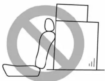
natural_image
Simple line drawing of a person sitting on the floor next to stacked boxes, with a no-smoking symbol overlay (no text or symbols present)100094

WARNING
- Neverstackluggageorother cargohigherthanthetopofthe seatbackbecauseitcouldtumble forwardandinjurepassengersin theeventof asuddenstop or accident.Keepluggageorcargo low,asclosetotheflooras
possible.
- When you carry something inside the vehicle, secure it whenever you cantopreventit from being thrown around inside the vehicle during sudden stops, sharp turns or an accident.
- Donotpileheavyloadsonthe roof. Theseloadsraisethevehicle'scenterofgravityandmakeit morepronetotipover.
- Securelengthyitemsproperlyto preventthemfromshootingforwardandcausingseriousinjury duringasuddenstop.
- Neverexceedthemaximumload limit.Ifyoudo,somepartson yourvehiclecanbreak,oritcan changethewayyourvehicle handles.Thiscouldresultinloss ofcontrol and causepersonal injury.Also,overloadingcan shortenthelifeofyourvehicle.
- Do not place anything on the extended luggage cover. Such items couldtumbleforward in theeventofasuddenstopora collision. Thiscouldcauseseriousinjury.
8-12Drivingtips

CAUTION
Donotcarryspraycans, containers with flammable or corrosively liquids or any other dangerous items inside the vehicle.
NOTE
Forbetterfueleconomy, donotcarry unneeded cargo.
■ Vehiclecapacityweight
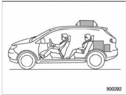
natural_image
Line drawing of a car with two people inside, showing driver and passenger (no text or symbols)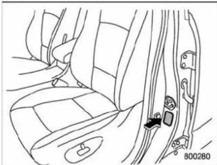
natural_image
Line drawing of car seat and seat assembly (no text or symbols)The load capacity of your vehicle is determined by weight, not by available cargospace. The maximum load you can carry in your vehicle is shown on the vehicle placard attached to the driver's sidedoorkillar. It includes the total weight of the driver and all passengers and their belongings, any optionale equipments such as atraler hitch, roofrackorbikecarrier, etc., and the longeload of a trailer.
GVWRandGAWR(Gross VehicleWeightRating and GrossAxleWeightRating)
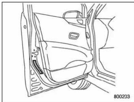
natural_image
Line drawing of a car interior showing the door, seat, and dashboard (no text or symbols)Certificationlabel
The certification label attached to the driver's sidedoor shows GVWR (Gross Vehicle Weight Rating) and GAWR (Gross Axle Weight Rating).
TheGVW(GrossVehicleWeight)must neverexceedtheGVWR.GVWisthe combinedtotalofweightofthevehicle, fuel, driver, allpassengers, luggage, any optionalequipmentandtrailertongue load. Therefore, theGVWchangesdependingonthesituation.
Inaddition, the total weight applied to each axle (GAW) must never exceed the GAWR. The front and rear GAW scan be
adjustedbyrelocating luggageinsidethe vehicle.
Evenifthetotalweightofyourluggageis lowerthanthevehiclecapacityweight, eitherfrontorrearGAWmayexceedthe GAWR,dependingonthedistributionof the luggage.
Whenpossible,theloadshouldbeevenly distributedthroughoutthevehicle. Ifyoucarryheavyloadsinthevehicle,you shouldconfirmthatGVWandfrontand rearGAWsarewithintheGVWRand GAWRbyputtingyourvehicleona vehiclescale,foundatacommercial weighingstation.
Donotusereplacementtireswithalower loadrangethantheoriginalsbecausethey maylowertheGVWRandGAWRlimitations.Replacementtireswithahigherload rangethantheoriginalsdonotincrease theGVWRandGAWRlimitations.
■Roofrailsandcrossbar(if equipped)

1) Roofrails
2) Crossbarkit

CAUTION
- Forcargocarryingpurposes, the roofrailmustbeusedtogether witharoofcrossbarkitandthe appropriatecarryingattachment. Therofrailmustneverbeused alonetocarrycargo. Otherwise, damagetotherooforpaintora dangerousroadhazarddueto lossofcargocouldresult.
- Whenusingtheroofcrossbarkit, makesurethatthetotalweightof
thecrossbars,carryingattach-mentandcargodoesnotexceed themaximumloadlimit.Over-loadingmaycausedamageto thevehicleandcreateasafety hazard.
Theroofrailsarenotdesignedtocarry cargobythemselves. Cargocanbe carriedaftersecuringtheroofcrossbar kittotheroofrailandinstallingthe appropriatecarryingattachment.When installingtheroofcrossbarkit,followthe manufacturer'sinstructions.
Whenyoucarrycangoontheroofusing theroofcrossbarkitandacarrying attachment,neverexceedthemaximum loadlimitasexplainedbelow.Youshould alsobecarefulthatyourvehicledoesnot exceedtheGrossVehicleWeightRating (GVWR)andfrontandrearGrossAxle WeightRating(GAWR).Forinformation onloadingcargointoorontoyourvehicle, referto"Loadingyourvehicle"8-11.The maximumloadlimitofthecargo,cross- barsandcarryingattachmentmustnot exceed 150 lbs (68 kg). Place the heaviestloadatthebottom,nearestthe roof,andevenlydistributethecargo. Alwaysproperlysecureallcargo.
8-14Drivingtips
▼Installingcarryingattachmentson thecrossbars
Wheninstallinganycarryingattachment suchasabikecarrier,skicarrier,kayak carrier,cargobasket,etc.onthecrossbars,followthemanufacturer'sinstructionsandmakesurethattheattachmentis securelyfixedtothecrossbars.Useonly attachmentsdesignedspecificallyforthe crossbars.Asetofthecrossbarsis designedtocarryloads(cargoandattachment)ofnotmorethan150lbs(68kg). Beforeoperatingthevehicle,makesure thatthecargoisproperlysecuredonthe attachment.
NOTE
Remember that the vehicle's center of gravity is altered with the weight of the load on the roof, thus affecting the driving characteristics.
Drivecarefully.Avoidrapidstarts,hard corneringandabruptstops.Crosswind effectswillbeincreased.
▼Removalandinstallationofthe crossbars
Thecrossbarscanberemovedwhenyou donotusetherooftocarrycargo.
Toremovethecrossbar
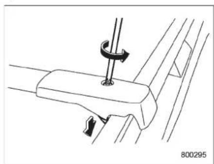
natural_image
Technical line drawing of a mechanical component with a hook and mounting bracket (no text or symbols)- LoosenandremovetheT-30torx® headscrewfromthetopofeachcrossbar endsupport.
Loosenthelowerclamps.
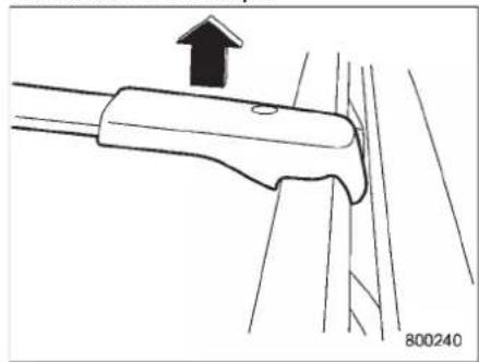
natural_image
Technical line drawing of a mechanical component with an upward arrow and page number 800240 (no text or symbols on the diagram itself)- Carefully raisethecrossbar from roof rails.
▽Toinstallthecrossbar Frontcrossbar:
Frontcrossbarhasa150lbs(68kg)load labelonleft-handside.
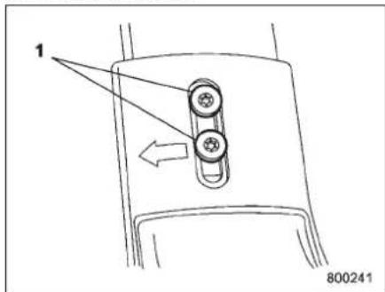
1) T-25torx®headscrew
-
MakesurethattheT-25torx®head screwonthebackofeachcrossbarend supportistightenedcorrectly.
-
Beforeplacing the crossbarontheroof rails, makesure that the T-30 torx® head screwis removed from the top of each crossbarendsupport.
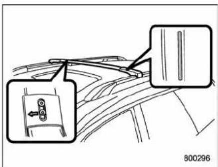
- Thecrossbarwitha150lbs(68kg) loadlabelattachedontoitisthefront crossbar.Anarrowismarkedontheback ofthefrontcrossbarforcorrectinstallation.Installthefrontcrossbarsothatthe arrowfacesthefrontofthevehicle.
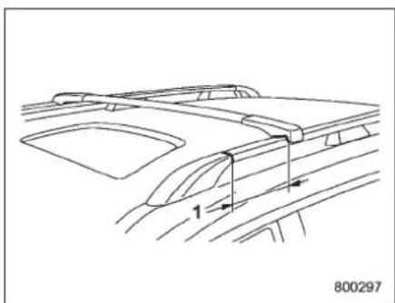
natural_image
Technical line drawing of a car interior frame with no visible text or symbols1)12in(300mm)
4. Install the front crossbar so that the crossbarend supports are located approximately 12 in (300 mm) rearward from the joints between thero off rails and the front roof rail supports.
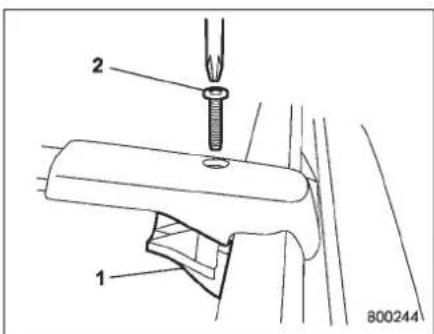
1) Lowerclamp
2)T-30torx®headscrew
5. Tightenthelowerclampsontothe crossbar. Usingatorquewrench, loosely tightenthe T-30torx® headscrews.
NOTE
Itmaybenecessarytosqueezethe lowerclamp and the endsupport togethertocompressthepadsand gainabetteralignmentofthepieces while tryingtostartthescrew. Usecare nottocross-threadthescrewinthe insert.
8-16Drivingtips
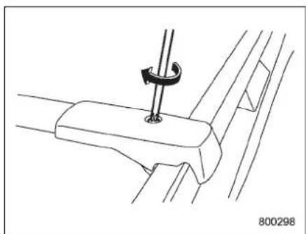
natural_image
Technical line drawing of a mechanical component with a clamp and bracket (no text or symbols)- Adjust the alignment of the crossbar on the oroofrails, and if available, use a T-30torx® bit and torque wrench and tighten the T-30torx® headscrewsto 30 to 35 lbf·in (3.4 to 4.0 N·m, 0.35 to 0.41 kgf·m) of torque (ortightense securely with the torx® wrench provided).
Rearcrossbar:
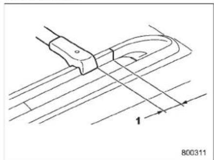
natural_image
Technical line drawing of a mechanical component with dimension lines and part number 1 (no text or symbols)1)2in(50mm)
Installtherearcrossbarsothatthecross-barendsupportsarelocatedapproximately2in(50mm)forwardfromthe jointsbetweenerofrailsandtherear roofrailsupports.
Installtherearcrossbarinthesame mannerasthefrontcrossbar.

CAUTION
Donotcarrycargoontheroofwhen thecrossbarsareremoved.Luggageontheroofwillbethrown forwardorbackwardinsudden stopsorrapidaccelerations,resultinginadangerousroadhazard.
NOTE
Beforeeachuseoftheroofcrossbar, makesurethefourT-30crossbar clampscrewshavebeenchecked, andretightenedifnecessaryto35lbf·in (4.0N·m,0.41kgf·m),asoutlined in Step#5above.
■ Roofmoldingandcrossbar (ifequipped)
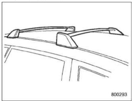
natural_image
Line drawing of a car front view showing roof, side panels, and window (no text or symbols)
CAUTION
- Forcargocarryingpurposes,the roofmoldingmustbe used togetherwitharoofcrossbarkit andtheappropriatecarryingattachment.Otherwise,damageto theooforpaintoradangerous
roadhazardduetolossofcargo couldresult.
- Whenusingtheroofcrossbarkit, makesurethatthetotalweightof thecrossbars,carryingattachmentandcargodoesnotexceed themaximumloadlimit.Overloadingmaycauseddamageto thevehicleandcreateasafety hazard.
Cargocanbecarriedaftersecuringthe roofcrossbarkittotheroofmoldingand installingtheappropriatecarryingattach-ment.Wheninstallingtheroofcrossbar kit,followthemanufacturer'sinstructions.
When you carry cargo on the roof, they will not have a minimum load limit as explained below. You should also be careful that your vehicle does not exceed the Gross Vehicle Weight Rating (GVWR) and front and rear Gross Axle Weight Rating (GAWR). Referto the "Loading your vehicle" section in this chapter for information on loading cargo into or to your vehicle. The maximum load limit of the cargo, crossbars and carrying attachment must not exceed 150 lbs (68kg). Placethe heaviest load at the bottom, nearest theroof, and evenly distribute the cargo. Always properly
secureallcargo.
▼Installingcarryingattachmentson thecrossbars
Wheninstallinganycarryingattachment suchasabikecarrier,skicarrier,kayak carrier,cargobasket,etc.onthecrossbars,followthemanufacturer'sinstructionsandmakesurethattheattachmentis securelyfixedtothecrossbars.Useonly attachmentsdesignedspecifallyforthe crossbars.Asetofthecrossbarsis designedtocarryloads(cargoandattachment)ofnotmorethan150lbs(68kg). Beforeoperatingthevehicle,makesure thatthecargoisproperlysecuredonthe attachment.
NOTE
Remember that the vehicle's center of gravity is altered with the weight of the load on the roof, thus affecting the driving characteristics. Drive carefully. Avoid rapid starts, hard cornering and abrupt stops. Crosswind effect will be increased.
▼Removalandinstallationofthe crossbars
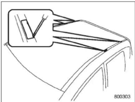
natural_image
Line drawing of a car's front wheel and side panel, showing engine and exhaust components (no text or symbols)Eachofthetworoofmoldingshastwo mountingpointsforcrossbars.Each mountingpointisfittedwithacover.Use ascrewdrivertoremovethecovers.When installingthecrossbarsontheroofmolding,followthemanufacturer'sinstructions.
8-18Drivingtips
Trailerhitch(ifequipped)
natural_image
Technical line drawing of a mechanical clamp or bracket assembly (no text or symbols)1) Trailerhitch

WARNING
- Neverexceed the maximum weightspecifiedforthetrailer hitch. Exceedingthemaximum weightcouldcauseanaccident resultinginseriouspersonalinjuries. Permissibletrailerweight changesdependingonthesituation. For possiblerecommendationsandlimitations, referto "Trailertowing" 8-20.
- Trailerbrakesarerequiredwhen thetowingloadexceeds 1,000 lbs(453kg).Besureyourtrailer
hassafetylchainsandthateach chainwillholdthetrailer'smaximumgrossweight.Towingtrailerswithoutsafetylchainscould createattraffic safety hazardif thetrailerseparatesfromthe hitchduetocouplingdamageor hitchballdamage.
- Be sure to check the hitch pin andsafetypinforpositivelocking placementbefore towing a trailer. If the ball mount comes off thehitchreceiver,thetrailer couldgetlooseandcreatea trafficsafetyhazard.
- Useonlytheballmountsupplied with this hitch. Use the hitch only as a weight carrying hitch. Do not use with any type of weight distributinghitch.
The maximum gross trailer weight and maximum gross tongue weight are indicated in the following table.
| Maximum grosstrailer weight | Maximum grosstongue weight | |
| Vehiclewith-out coolingkit | 2,000lbs (906kg) | 200lbs (90kg) |
| Vehiclewith coolingkit | 3,500lbs (1,587kg) | 350lbs (158kg) |
Whenyoutowatrailer, followtheinstructionsin"Trailertowing" 8-20.
■ Connectingatrailer
- Remove thereceiveroverfromthe hitchreceiver tube. Then insert the ball mount into the hitch receivertube.
natural_image
Line drawing of a mechanical component with a directional arrow and label '800257' (no readable text or symbols)- Insert the hitchpin into the hole on the hitch receive vertubes that the pin passes through the ball mount.
natural_image
Technical line drawing of a mechanical component with no visible text or symbols- Insert the safetypin into the hitchpin securely.
- Pulltheballmounttomakesureit doesnotcomeoffthehitchreceiver.
1) Hitchball installation point
2) Hooksforsafetychains
- Use only a hitchball that is appropriate for the ball mount and your trailer. The hitchball must be securely installed on the ball mount.
- Connectyourtrailertothehitchball.
- Connect the trailer and the hitch with safety chain that will hold the trailer's maximum gross weight. The chains should cross under the trail to tongue to prevent the tongue from dropping onto the ground case it should disconnect from the hitch ball. Allows sufficient slack in the chains taking tight-turn situations into account; however, be careful not to let them dragon the ground.
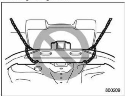
natural_image
Technical line drawing of a vehicle head assembly with no visible text or symbols
WARNING
Donotconnectsafetychainstopart ofthevehicleotherthanthesafety chainhooks.
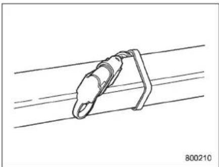
natural_image
Technical line drawing of a mechanical clamp or bracket attached to two parallel wires (no text or symbols)Hitchharnessconnector
- Connect the hitchwire harness's black four-pin wire connector to the towing trailer's wire harness.
- Confirm proper function of the hitch wire harness by individually activating the brake, rightturnsignal, leftturnsignal, stop, and parking lightson the trailer.
NOTE
Always disconnect the trailer wire harness before launching or retrievinga
-CONTINUED-
8-20Drivingtips
watercraft.
■Whenyoudonottowatrailer
- Removetheballmountfromthehitch receivertubeandinsertthereceivercover ontothehitchreceivertube.
- Placethedustcapoverthefour-pin connectorofthehitchwireharnessto protectagainstpossibledamage.
- Occasionallylubricateterminalsofthe four-pinconnectorusingtheterminal grease.
Trailertowing
Yourvehicleisdesignedandintendedto beusedprimarilyasapassenger-carrying vehicle. Towingatrailerputsadditional loadsonyourvehicle'sengine,drivetrain, brakes,tiresandsuspensionandhasan adverseeffectonfueleconomy. Ifyoudodecidetotowatrailer,yoursafety andsatisfactiondependuponproperuse ofcorrectequipmentandcautiousoperationofyourvehicle.Seektheadviceof your SUBARU dealer to assist you in purchasingahitchandothernecessary towing equipment appropriate for your vehicle.Inaddition,besuretofollowthe instructionsoncorrectinstallationanduse providedbythetrailerandothertowing equipmentmanufacturers. SUBARUassumesnoresponsibilityfor injuriesorvehicledamagethatresultfrom trailertowingequipment,orfromany errors or omissions in the instructions accompanyingsuchequipmentorforyour failuretofollowtheproperinstructions.
■Warrantiesandmaintenance
SUBARUwarrantiesdonotapplyto vehicle damageor malfunction caused bytrailertowing.Ifyouuseyourvehicleto towatrailer,morefrequentmaintenance willberequiredduetotheadditionalload.
(Referto "Maintenancescheduleunder severedrivingconditions" in the "Warranty and MaintenanceBooklet".)
Undernocircumstances should datrailer betowed with anew vehicle or a vehicle with any new power train component (engine, transmission, differential, wheel bearings, etc.) for the first 1,000 miles (1,600 km) of driving.
■Maximumloadlimits

WARNING
Neverexceedthemaximumload limitsexplained inthefollowing. Exceedingthemaximumloadlimits couldcausepersonalinjuryand/or vehicledamage.

CAUTION
- Adequatesizetrailerbrakesare requiredwhenthetrailerandits cargoexceed1,000lbs(453kg) totalweight.
- Beforetowingatrailer,checkthe trailertotalweight,GVW,GAWs andtongueload.Makesurethe loadanditsdistributioninyour vehicleandtrailerareaccepta-
ble.
▼Totaltrailerweight
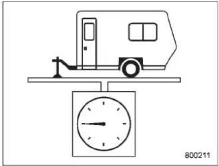
natural_image
Simple line drawing of a vehicle on a scale with a wall-mounted gauge (no text or symbols)Totaltrailerweight
The total trailer weight (trailer weight plus its cargoload) must never exceed the maximum weight shown in the following table.
Vehiclewithoutcoolingkit
| ConditionsMaximumtotaltrailerweight | |
| Whentowingatrailerwithoutbrakes.1,000lbs(453kg) | |
| Whentowingatrailerwithbrakes.2,000lbs(906kg) | |
| Whentowingatraileronalonguphillgradecontinuouslyforover5miles(8km)withanoutsidetemperatureof 104^ F( 40^ C)orabove. | 1,000lbs(453kg) |
Vehiclewithcoolingkit
| ConditionsMaximumtotaltrailerweight | |
| Whentowingatrailerwithoutbrakes.1,000lbs(453kg) | |
| Whentowingatrailerwithbrakes.3,500lbs(1,587kg) | |
| Whentowingatraileronalonguphillgradecontinuouslyforover5miles(8km)withanoutsidetemperatureof 104^ ( 40^ )orabove. | 1,750lbs(794kg) |
8-22Drivingtips
▼GrossVehicleWeight(GVW)and GrossVehicleWeightRating (GVWR)
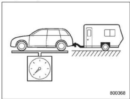
natural_image
Line drawing of a car on a scale with a speedometer and a parked vehicle nearby (no text or symbols)GrossVehicleWeight
TheGrossVehicleWeight(GVW)must neverexceedtheGrossVehicleWeight Rating(GVWR).
GrossVehicleWeight(GVW)is the combined total of the weight of the vehicle, driver, passengers, luggage, trailerhitch, trailertongueload and any other optional equipment installed on your vehicle.
Therefore,theGVWchangesdepending onthesituation.DeterminetheGVWeach timebeforegoingonatripbyputtingyour vehicleandtraileronavehiclescale.
GVWRisshownonthecertificationlabel locatedonthedriver'sdoorofyour vehicle.
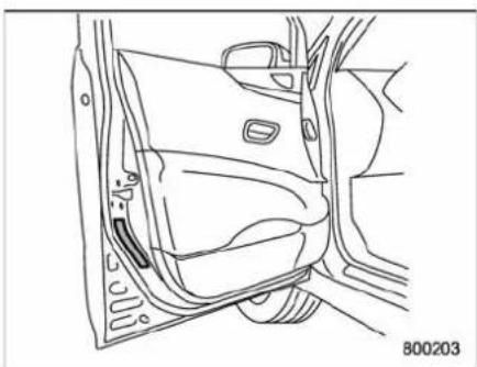
natural_image
Line drawing of a car interior showing the door, seat, and window (no text or symbols)Certificationlabel
▼GrossAxleWeight(GAW)and GrossAxleWeightRating(GAWR)
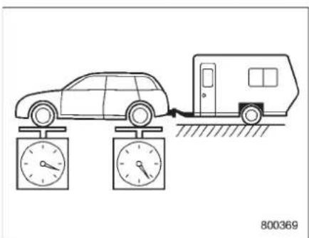
GrossAxleWeight
Thetotalweightappliedtoeachaxle
(GAW)mustneverexceedtheGrossAxle WeightRating(GAWR).Thefrontandrear GAWscanbeadjustedbyrelocating passengersandluggageinsidethevehicle. ThefrontandrearGAWRarealso shownonthecertificationlabel.
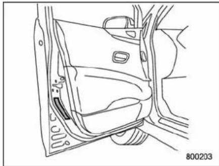
natural_image
Line drawing of a car interior showing the door, seat, and side panel (no text or symbols)Certificationlabel
TocheckbothGVWRandGAWRandto confirmthatthetotalweightandweight distributionarewithinsafedrivinglimits, youshouldhaveyourvehicleandtrailer weighedatacommercialweighingstation. Besurethatallcargoisfirmlysecured to preventachangeinweightdistribution whiledriving.
▼Tongueload
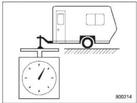
Tongueload

WARNING
If the trailer is loaded with more weight in the back of trailer's axle than in the front, the load is taken off therear axle of the towing vehicle. This may cause the rear wheel to skid, especially during braking or when vehicles speed is reduced during cornering, resulting in oversteer, spin out and/or jack knifing.
Ensure that the trail is to load from 8 to 11 percent of the total trailer weight and does not exceed the appropriate one of the following maximum values.
Vehiclewithoutcoolingkit:200lbs(90kg) Vehiclewithcoolingkit:350lbs(158kg)
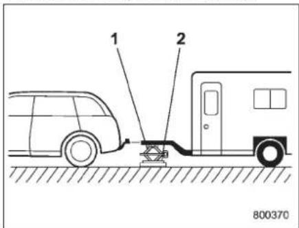
1) Jack
2)Bathroomscale
Thetongueloadcanbeweighedwitha bathroomscaleasshownintheillustration above. Whenweighingthetongueload, besuretopositionthetowingcouplerat theheightatwhichitwouldbeduring actualtowing, usingajackasshown.
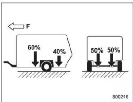
F:Front
Thetongueloadcanbeadjusted by proper distribution of the load in the trailer. Never load the trailer with more weight in the back than the front; approximately 60 percent of the trailer load should be in the front and approximately 40 percent in therear. Also, distribut the load a sevenly as possible on both the left and right sides.
Besurethatallcargoisfirmlysecuredto preventachangeinweightdistribution whiledriving.
Trailerhitches

WARNING
Neverdrilltheframeorunder-body
-CONTINUED-
8-24Drivingtips
ofyourvehicletoinstallacommercialtrailerhitch.Ifyoudo,danger-ousexhaustgas,waterormudmay enterthepassengercompartment throughthedrilledhole.Exhaust gascontainscarbonmonoxide,a colorlessandodorlessgaswhichis dangerous,orevenlethal,ifinhaled. Also,drillingtheframeorunder-bodyofyourvehiclecouldcause deteriorationofstrengthofyour vehicleandcausecorrosionaround thedrilledhole.

CAUTION
- Donotmodifythevehicleex-haustsystem,brakesystem,or othersystemswheninstallinga hitchorothertrailertowing equipment.
- Donotuseaxle-mountedhitches astheycancausedamagetothe axlehousing, wheelbearings, wheelsortires.
Chooseaproperhitchforyourvehicleand trailer.
TheuseofagenuineSUBARUtrailer hitch is recommended. Agenuine SUBARUhitchisavailablefromyour
SUBARUdealer.
If use of a non-genuine hitch is unavoidable, besurethehitchissuitedtoyour vehicle and trailer. Consult with a professionalhitchsuppliertoassistyouin choosinganappropriatehitchforyour vehicle. Be sure to follow all of the hitch manufacturer'sinstructionsforinstallation anduse.
Never use a hitch that mounts only to the rear bumper. The bumper is not designed to handle that type of load.
For all types of hitches, regularly check that the hitch mounting bolts and nuts are tight.
■ Connecting a trailer
▼Trailerbrakes

WARNING
- Adequatesizetrailerbrakesare required when the trailer and its cargoexceed1,000lbs(453kg) total weight.
- Donotdirectlyconnectyour trailer's hydraulic brake system tothe hydraulic brakesystem in yourvehicle.Directconnection would causethevehicle's brake performancetodeteriorateand
could lead toan accident.
If your trailer's total weight (trailer weight plus its cargo weight) exceeds 1,000 lbs (453kg), the trailer is required to be equipped with its own brakes system. Electric brakes surge brakes are recommended, and must be installed properly. Check that your trailer's brakes conform with Federal, state/province and/or other applicable regulations. Your SUBARU's brakes system is not designed to be tapped into the trailer's hydraulic brake system. Please ask your SUBARU dealer and professional trailer supplier for more information about the trailer's brake system.
▼Trailersafety chains

WARNING
Alwaysusesafetychainsbetween your vehicle and thetrailer.Towing trailerwithout safetychains could createatrafficsafetyhazardifthe trailer separatesfrom thehitch due tocouplingdamageorhitchball damage.
In case the trailer hitch connector or hitch ballshouldbreakorbecomedisconnected, the trailercouldgetloose and
createatrafficsafetyhazard.
Forsafety, alwaysconnectthetowing vehicle and trailerwithtrailersafety chains. Passthechainscrossingeach otherunderthetailertonguetoprevent thetrailerfromdroppingontotheground incasethetailertongueshoulddisconnectfromthehitchball. Allowsufficient slackinthechainstakingtight-turnsituationsintoaccount; however, becarefulnot toletthemdragontheground.
Formoreinformationaboutthesafety chainconnection, refertotheinstructions foryourhitchandtrailer.
▼Sidemirrors
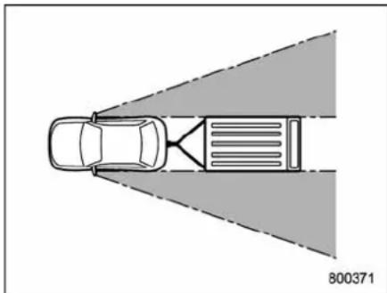
natural_image
Top-down diagram of a car with a vehicle and road markings, no text or symbols presentAfterhitchingatrailertoyourvehicle, checkthatthestandardsidemirrors provideagoodrearwardfieldofview withoutsignificantblindspots.Ifsignificant
blindspotsoccurwiththevehicle'sstandardsidemirrors,usetowingmirrorsthat conformwithFederal,state/provinceand/orotherapplicableregulations.
▼Trailerlights

CAUTION
Directsplicingorotherimproper connectionoftrailerlightsmay damageyourvehicle'selectrical systemandcauseamalfunctionof yourvehicle'slightingsystem.
Connectionoftrailerlightstoyourvehicle'selectricalsystemrequiresmodificationstothevehicle'slightingcircuittoincreaseitscapacityandaccommodate wiringchanges.Toensurethetrailerlights areconnectedproperly,pleaseconsult yourSUBARUdealer.Checkforproper operationoftheturnsignals,the brake lights and parking lights each time you hitchup.
▼Tires

WARNING
Never tow a trailer when the temporarysparetireisused. Thetemporarysparetireisnotdesignedto sustainthetowingload.Useofthe
temporarysparetirewhentowing canresultinfailureofthesparetire and/orlessstabilityofthevehicle.
Makesurethatallthetiresonyourvehicle areproperlyinflated.
Therecommended cold tire pressure undertrailertowing conditions is shown in "Tires" 12-3 and in "GAS STATION REFERENCE" at the end of this manual. Adjust there are tire pressure to the recommended pressure when the tires are cold. Normal pressures should be maintained in the front tires.
Trailertirecondition,size,loadratingand properinflationpressureshouldbein accordancewiththetrailermanufacturer's specifications.
Intheeventyourvehiclegetsaflattire whentowingatrailer,askacommercial roadservicetorepairtheflattire.
If you carry regular sizes spare tire in your vehicle or trailer as a precaution against getting a flattire, besure that the spare tire is firmly secured.
8-26Drivingtips
■ Trailertowingtips

CAUTION
●Neverexceed45mph(72km/h) whentowingatrailerinhilly countryonhotdays.
- Whentowingatraler,steering, stability,stoppingdistanceand brakingperformancewillbedifferentfromnormaloperation.For safety'ssake,youshouldemploy extracautionwhentowinga trailerandyoushouldnever speed.Youshouldalsokeepthe followingtipsinmind:
▼Beforestartingoutonatrip
- Check that the vehicle and vehicle-to-hitch mounting are good condition. If any problems are apparent, do not tow the trailer.
- Checkthatthevehiclesitshorizontally withthetrailerattached.Ifthevehicleis tippedsharplyupatthefrontanddownat therear,checkthetotal trailerweight, GVW,GAWsandtongueloadagain,then confirm that the load and its distribution areacceptable.
- Check that the tire pressures are correct.
- Checkthatthevehicleandtrailerare connectedproperly.Confirmthat
-thetrailertongueisconnected properlytothehitchball.
- the trailer lights connector is connected properly and trailer's brake lights illuminate when the vehicle's brakepedalispressed, and that the trailer's turn signal lights flash when the vehicle's turn signal leverisoperated.
—the safetychainsareconnected properly.
– allcargointhetrailerissecured safelyinposition.
-the sidemirrorsprovideagood rearward field of view without a significantblindspot.
- Sufficienttimes should betakentolearn the "feel" of the vehicle/trailer combination before starting out on a trip. In an area free of traffic, practiceturning, stopping and backing up.
▼ Drivingwithatrailer
- You should allow for considerably more stopping distance when towing a trailer. Avoid sudden braking because it may result in sickling or jackknifing and loss of control.
-
Avoid unevensteering, sharpturnsand rapidlanechanges.
-
Slow down before turning. Make a longerthan normalturningradiusbecause the trailerwheelswillbecloserthanthe vehiclewheelstotheinsideoftheturn.In a tight turn, the trailer could hit your vehicle.
- Crosswinds will adversely affect the handling of your vehicle and trailer, causing way. Crosswinds can be due to weather conditions or the passing of large truck or buses. If swaying occurs, firmly grip the steering wheel and slowdown immediately but gradually.
- When passing other vehicles, considerable distance is required because of the added weight and length caused by attaching the trail to your vehicle.
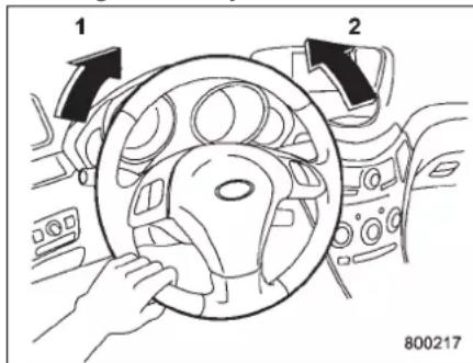
1) Leftturn
2) Rightturn
- Backingupwithatralerisdifficultand takespractice. Whenbackingupwitha trailer,neveraccelerateorsteerrapidly. Whenturningback,gripthebottomofthe steeringwheelwithonehandandturnitto theleftforaleftturn,andturnitotheright forarightturn.
- If the ABS warning light illuminates while the vehicle is in motion, stoptowing the trailer and haverepairs performed immediately by the nearest SUBARU dealer.
▼Drivingongrades
- Beforegoingdownasteephill, slow downandshiftintolowergear(ifnecessary, use1stgear)inordertoutilizethe enginebrakingeffectandpreventoverheatingofyourvehicle'sbrakes. Donot makesuddendownshifts.
- Whendrivinguphillinhotweather, the airconditionermayturnoffautomatically toprotecttheenginefromoverheating.
- Whendrivinguphillinhotweather, pay attentiontothewatertemperaturegauge pointerandATOILTEMPwarninglight because the engine and transmission are relatively proneto overheating under these conditions. If the watertemperature gauge pointer approachesthe OVERHEATzoneortheATOILTEMP warning lightilluminates, immediately turnoff the
airconditionerandstopthevehicleinthe nearestsafelocation.Forfurtherinstructionsandadditionalinformation,referto thefollowingsections.
- “ If you park your vehicle in an emergency” 9-2
- “Engineoverheating”9-14
- “Temperaturegauge” 3-9
- "AT OIL TEMP warning light" 3-13
NOTE
Thetemperatureofenginecoolantis lesslikely toriseto the OVERHEAT zoneinthe“D”positionthaninthe manualmodeposition.
- Avoidusingtheacceleratorpedalto staystationaryonanuphillslopeinstead ofusingtheparkingbrakeorfootbrake. Thatmaycausethetransmissionfluidto overheat.
▼Parkingonagrade
Alwaysblockthewheelsunderboth vehicleandtrailerwhenparking.Apply theparkingbrakefirmly.Youshouldnot parkonahillorslope.Butifparkingona hillorslopecannotbeavoided,you shouldtakethefollowingsteps.
- Applythebrakesandholdthepedal down.
-
Havesomeoneplacewheelblocks underboththevehicleandtrailerwheels.
-
Whenthewheelblocksareinplace, releasetheregularbrakesslowlyuntilthe blocksabsorbtheload.
- Applytheregularbrakesandthen applytheparkingbrake;slowlyrelease theregularbrakes.
- Shiftinto"P"andshutofftheengine.
| -1.5 | -1.5 | -1.5 | -1.5 |
In case of emergency
If you park your vehicle in an emergency......9-2
Sparetire....9-2
Removingthesparetire....9-3
Re-storageofsparetire....9-4
Temporarysparetire....9-5
Flattires....9-6
Changingaflattire....9-6
Tirepressuremonitoringsystem(TPMS)....9-11
Jumpstarting....9-12
Howtojumpstart....9-12
Engineoverheating....9-14
lfsteamiscomingfromtheengine compartment....9-14
Ifnosteamiscomingfromtheengine compartment....9-14
Towing....9-14
Towingandtie-downhooks....9-15
Usingaflat-bedtruck....9-17
Towingwithallwheelsontheground.... 9-17
Reargate-ifthereargatecannotbe unlocked....9-18
Maintenancetools....9-19
Jackandjackhandle.... 9-19
9-2 Incaseofemergency
If you park your vehicle in an emergency
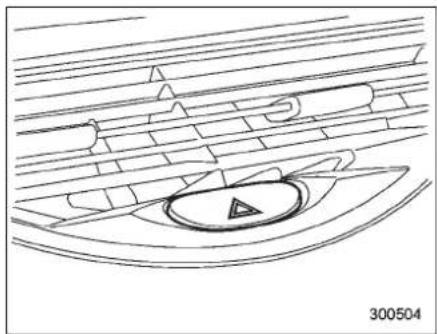
natural_image
Line drawing of a boat with a circular center and triangular pattern, surrounded by horizontal lines (no text or symbols)Thehazardwarningflashershouldbe usedindayornighttowarnotherdrivers whenyouhavetoparkyourvehicleunder emergencyconditions.
Avoidstoppingontheroad.Itisbestto safelypullofftheroadifaproblemoccurs.
Thehazardwarningflashercanbeactivatedregardlessoftheignitionswitch position.
Turnonthehazardwarningbypushing thehazardwarningflasherswitch.Turnit offbypushingtheswitchagain.
NOTE
Whenthehazardwarningflasherison, theturnsignalsdonotwork.
Sparetire
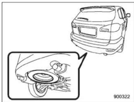
natural_image
Line drawing of a car front view and its close-up of the wheel assembly (no text or symbols)Thesparetireisstoredinthesparetire holderlocatedunderthecargoarea.
Thesparetireholderhasahoistmechanismthatcanlowerandraisethesparetire easily.
Thesparetireholderisdesignedtocarry onlythefollowingkindsoftires.
- the temporary spare tire that camewith your vehicle
- afull-sizeflattire
Afullsizeflattireshouldbestowedinthe sparetireholderinanemergencyonly. Afterhavingthefull-sizeflattirerepaired, immediatelyswapitwiththetemporary sparetire.
Beforeusingthetemporarysparetire,
carefullyread"Temporarysparetire" 9-5 forinstructionsandprecautions.
■Removingthesparetire
- Takethewheelnutwrenchandextensionoutofthetoolbag. Referto "Maintenancetools" 9-19.
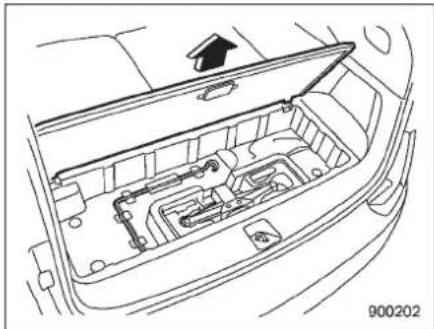
natural_image
Line drawing of an open car interior with internal components and a graduation cap icon (no text or symbols)- Removethesubfloorstoragelidinthe cargoarea.
3.Takeoutthejack. - Locatethehex-headhoistshaftend insidethehole.
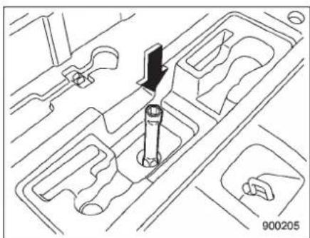
natural_image
Technical line drawing of a mechanical gear assembly with no visible text or symbols- Fittheextensionontothehex-head hoistshaftend.
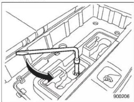
natural_image
Technical line drawing of a vehicle engine bay with a wrench and valve (no text or symbols)6.Fitthewheelnutwrenchontothe extension.
7. Turnthehoistshaftendcounterclock-wisewiththewheelnutwrenchuntilthe
temporarysparetireisonthegroundwith enoughcableslacktoallowyoutopullit outfromunderthevehicle.

CAUTION
- Besuretoremove(notsimply keepitopen)thesubfloorstoragelidbeforeturningthewheel nutwrench,otherwisethelid maybedamaged.
- Donotputyourfingersintothe centerholeofthetemporary sparetirewhileyoupullingit out, because theymightbe pinchedinbetweenthewheel andtheretainer.
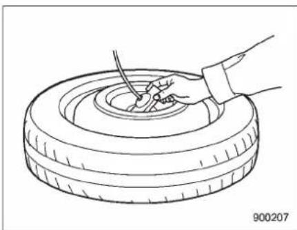
natural_image
Line drawing of a hand using a tool to lift a tire (no text or symbols)- Tilttheretainerattheendofthecable
-CONTINUED-
9-4 Incaseofemergency
andpulllithroughthecenterofthe temporarysparetire. 9. After the temporarysparetire is removedfromthecable, thecable must bewoundupcompletelybyturningthe hoistnutshaftclockwiseuntilyouheara clickingsound. Alsovisuallyinspectthe cabletomakecertainthatthereisno longeranyslackpresent.
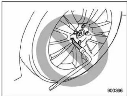
natural_image
Diagram of a car wheel assembly with a tool, showing no text or symbols
WARNING
- Donotusetheextensionwhen turningthewheelnuts.Ifyoudid, youwouldnotbeabletoachieve sufficienttighteningtorque.The wheelnutscouldthencome loose,resultinginaserious accident.
- Whenusingthesparetirehoist:
Afterthetemporarysparetireis removedfromthecable, windthe cableupcompletelyuntilthe retaineratendofthecablesits againstthe undersideofthe vehicle. Drivingwiththecable notretractedfullycouldresultin damagetoheadjacentunder floorpartsandleadtoaserious accident.
- Thesparetireholderisdesigned tocarryonlythefollowingkinds oftires.
-thetemporarysparetirethat camewithyourvehicle -afull-sizeflattire
A full size flat tire should be stowedinthesparetireholder inanemergencyonly.Afterhavingthefull-sizeflattirerepaired, immediately swap it with the temporarysparetire.
Neverstowafull-sizetirethatis notflatinthesparetireholder. Doingsocanresultindamageto adjacentunderfloorpartsand canleadtoaseriousaccident.

CAUTION
When using the spare tire hoist: Donot use air tools or powertools to turn the spare tire hoist shaft. If you do, it could result in severe mechanical damage to the spare tire hoist.
■ Re-storageofsparetire
- Turnthesparetirehoistshaftend counterclockwisewith the wheelnut wrench to loosenthecables sufficiently enough to allow the cable end retainergo through centerhole of the temporary spare tire.
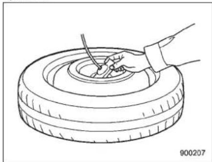
natural_image
Line drawing of a hand using a tool to clean or repair a tire (no text or symbols)- Inserttheretainerthroughthecenter holeofthetemporarytire(withtheoutside
ofthetirefacingup).
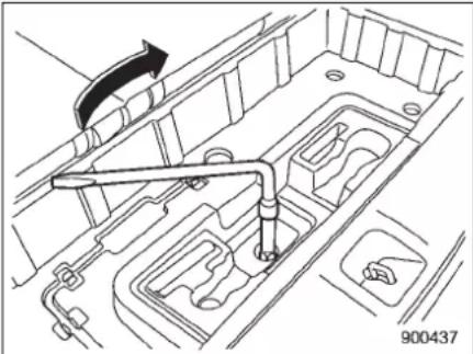
natural_image
Technical line drawing of a vehicle engine compartment with a hand operating the valve (no text or symbols)- Turnthehoistshaftendclockwisewith thewheelnutwrenchtowindthecableup completelyuntilyouhearafewclicking sounds. Confirmthatthetemporaryspare tireholdingcablehasbeenwoundup completelybyshakingthetemporarytire.

CAUTION
If the temporary spare tire is not stored securely, it could damage adjacent areas of the vehicle and make an abnormal noise.
-
Placethewheelnutwrenchand extensionbackintothetoolbagandstore thejackandtoolbagintheirstorage locations.
-
Fitthelidofthecargoarea.

CAUTION
- Whenstowingaflattireinthe sparetireholder,turnthehoist shaftendonlyslowly.Ifitis turnedquickly,thewheeldiscof theflattirecouldbedamaged.
- Afull-sizeflattireshouldbe stowedinthesparetireholder inanemergencyonly.Afterhavingtheflattirerepaired,immediatelyswapitwiththetemporary sparetire.
- Rememberthatthetreadwidth of aflattireiswiderthanthatofthe temporary spare tire. When carryingaflattirestowedinthe spare tireholder,makesurethe tiredoesnottouchanyobstacles.
Temporary spare tire

WARNING
- Nevertowatrailerwhenthe temporarysparetireisused. Thetemporarysparetireisnot designedtosustainthetowing load.Useofthetemporarysparetirewhentowingcanresultin failureofthesparetireand/or lessstabilityofthevehicleand mayleadtoanaccident.
- Whenaspare tire ismountedora wheelrimisreplacedwithoutthe originalpressuresensor/transmitterbeingtransferred,thelow tirepressurewarninglightwill illuminate steadilyafterblinking forapproximatelyoneminute. Thisindicatesthetirepressure monitoringsystem(TPMS)isunabletomonitorallfourroad wheels.ContactyourSUBARU dealerassoonaspossiblefor tireandsensorreplacementand/orsystemresetting.
-CONTINUED-
9-6 Incaseofemergency

CAUTION
Neveruseanytemporarysparetire otherthantheoriginal.Usingother sizesmayresultinseveremechanicaldamagetothedrivetrainofyour vehicle.
Thetemporarysparetireissmallerand lighterthanaconventionaltireandis designedforemergencyuseonly. Removethetemporarysparetireandreinstalltheconventionaltireassoonas possiblebecausethesparetireisdesignedonlyfortemporaryuse.
Checktheinflationpressureofthetemporarysparetireperiodicallytokeepthe tirereadyforuse. The correct pressure is 60 psi (420 kPa, 4.2 kgf/cm ^2 ).
When using the temporary spare tire, note the following.
- Donotexceed50mph(80km/h).
- Donotputatirechainonthetemporary spare tire. Because of the smallest tiresize, atirechain will not fit properly.
- Donotusetwoormoretemporary sparetiresatthesametime.
- Donotdriveoverobstacles. Thistire hasasmallerdiameter, soroadclearance isreduced.
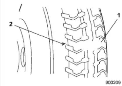
1) Treadwearindicatorbar
2) Indicatorlocationmark
- Whenthewearindicatorappearson thetread, replacethetire.
- Thetemporarysparetiremustbeused onlyonarearwheel. If a front wheeltire gets punctured, replace the wheel with a rearwheeland install the temporary spare tire in place of the removed rearwheel.
Flattires
If you have a flattire while driving, never brakes suddenly; keep driving straight ahead while gradually reducing speed. Thenslowly pullofftheroad to as safe place.
■Changingaflattire

WARNING
- Donotjackupthevehicleonan inclineora looseroadsurface. Thejackcancomeoutofthe jackingpointorsink intothe groundandthiscanresultina severeaccident.
- Useonlythejackprovidedwith your vehicle.The jacksupplied withthevehicleisdesignedonly forchangingatire.Never get underthevehiclewhilesupportingthevehiclewiththisjack.
- Alwaysturnofftheenginebefore raisingtheflattireofftheground usingthejack.Neverswingor pushthevehiclesupportedwith thejack.Thejackcancomeout ofthejackingpointduetoajolt andthiscanresultinasevere accident.
- Parkonahard, levelsurface, whenever possible, thenstoptheengine.
- Settheparkingbrakesecurely and shiftinthe"P"(Park)position.
- Turnonthehazardwarningflasher and have everyonegetoutofthevehicle.
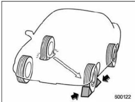
natural_image
Diagram of a car with wheels and a moving object, showing motion direction (no text or symbols)- Putwheelblocksatthefrontandrear ofthetirediagonallyoppositetheflattire.
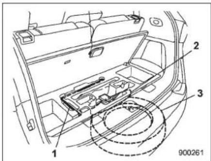
7-seatermodels
- Takeoutthejackandjackhandle.
Thejackandjackhandlearestoredunder thefloorofthecargoarea.
- Removethesparetire. Referto "Sparetire" 9-2 for its location, instructions and precautions.
Carefullyread"Temporarysparetire" 9-5andstrictlyfollowtheinstructions.
NOTE
Makesurethejackiswelllubricated beforeusingit.
-CONTINUED-
9-8 Incaseofemergency
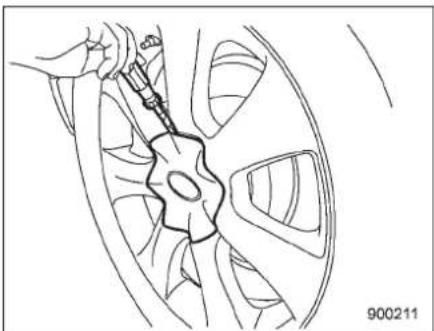
natural_image
Line drawing of a car wheel with a hand holding a tool, no text or symbols presentChromeplatedwheels
- Insert the tip (wrapped in vinyl tapeor acloth) of a flat-head screw driver into the slot between the wheel and the slot between the wheel and the slot between the wheel and the slot between the wheel and the slot between the wheel and the slot between the wheel and the slot between the wheel and the slot between the wheel and the slot between the wheel and the slot between the wheel and the slot between the wheel and the slot between the wheel and the slot between the wheel and the slot between the wheel and the slot between the wheel and the slot between the wheel and the slot between the wheel and the slot between 1000
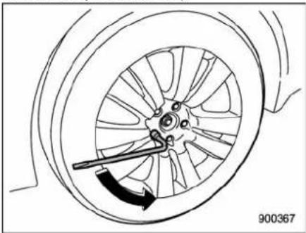
natural_image
Diagram of a car wheel with a tool inserted, showing motion direction (no text or symbols)- Loosenthewheelnutsusingthewheel nutwrenchbutdonotremovethenuts.
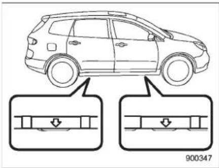
- Placethejackunderthesidesillatthe frontorrearjack-uppointclosesttotheflat tire.
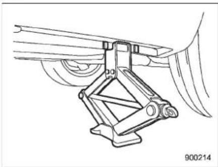
natural_image
Technical line drawing of a mechanical assembly with no visible text or symbolsTurnthejackscrewbyhanduntilthejack
headengagesfirmlyintothejack-uppoint.
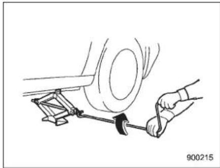
natural_image
Line drawing of a car wheel being adjusted with a tool, no text or symbols present-
Insert the jack handle into the jack-screw, and turn the handle until the tire clear the ground. Donot rais the vehicle higher than necessary.
-
Removethewheelnutsandtheflat tire.
-
Removethetirecoverifthetemporary sparetirehasacover.
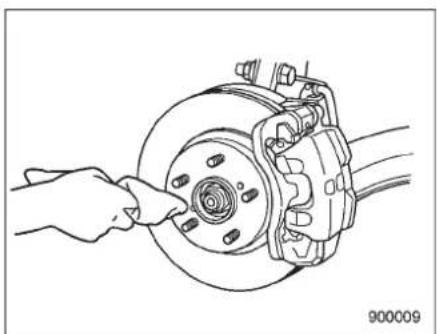
natural_image
Line drawing of a hand adjusting a car brake caliper on a wheel (no text or symbols)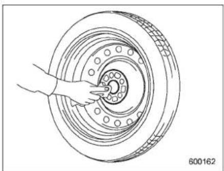
natural_image
Line drawing of a hand fastening a car tire with a circular component (no text or symbols)- Beforeputtingthesparetireon, clean themountingsurfaceofthewheelandhub withacloth.
- Putonthesparetire. Replacethe wheelnuts. Tightenthembyhand.

WARNING
Donotuseoilorgreaseonthe wheelstudsornutshwhenthespare tireisinstalled. This could cause the nutstobecomelooseandleadtoan accident.
- Turn the jack handle counterclockwise to lower the vehicle.

CAUTION
Thereare2typesofwheelnut wrenchesthatapplytodifferent lengths.
Foranaluminumwheelvehicle,the 11.2-inch (285 mm) wheel nut wrenchisequippedasamaintenancetool.Andforachromeplated wheel vehicle,the 13.2-inch(335 mm)wheelnutwrenchisequipped aswell.Confirmtheequippedwheel nutwrenchtypewhenyoureplace tire.Ifthewheelnutwrenchisthe differenttype,itcannotbetightened tothespecifiedtorque.
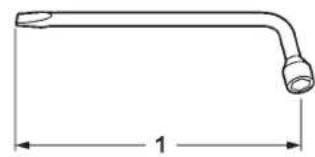
natural_image
Simple line drawing of a bent pipe or tube with a dimension label (no text or symbols)900292
1) Thelengthofthewheelnutwrench
- Confirmthelengthoftheequipped wheelnutwrench. Foranaluminumwheelvehicle,the11.2-inch(285mm)wheelnutwrenchis equippedasamaintenancetool.Andfor achromeplatedwheelvehicle,the13.2-inch(335mm)wheelnutwrenchis equippedaswell.
-CONTINUED-
9-10 Incaseofemergency
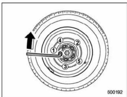
- Usethewheelnutwrenchtosecurely tightenthewheelnutstothespecified torque, following the tightening order in the illustration.
Wheelnutstighteningtorquefortemporarysparetire:
74to89lbf·ft(100to120N·m,10to12kgf·m)
Thisorqueisequivalenttoapplyingthe followingloadontheedgeofthewheel nutwrench.
Whenyouuseawheelnutwrenchof the11.2-inch(285mm)length: Approximately88to110lbs(40to50 kg)
Whenyouuseawheelnutwrenchof the13.2-inch(335mm)length: Approximately73to87lbs(33to38kg)
Neveruseyourfootonthewheelnut wrenchorapipeextensiononthewrench becauseyoumayexceedthespecified torque. Have the wheel nut torque checked at thenearestautomotiveservice facility.
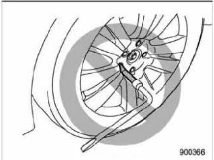
natural_image
Diagram of a car wheel assembly with a tool, showing no text or symbols
WARNING
Donotusetheextensionwhen turningthewheelnuts.Ifyoudid, youwouldnotbeabletoachieve sufficienttighteningtorque.The wheelnutscouldthencomeloose, resultinginaseriousaccident.
- Storetheflattireinthesparetire holder.
Referto "Sparetire" 9-2 for its location, instructions and precautions.

CAUTION
- Whenstowingaflattireinthe spareireholder,turnthehoist shaftendonlyslowly.Ifitis turnedquickly, thewheel disc of theflattirecouldbedamaged.
- Afull-sizeflattireshouldbe stowedinthesparetireholder inan emergencyonly. After havingtheflattirerepaired,immediatelyswap itwiththetemporary sparetire.
- Remember that the thread width of aflattire is wider than that of the temporary spare tire. When carrying a flattire stowed in the spare tire holder, makes sure the tired does not touch any obstacles.

WARNING
Neverplaceatireortirechanging toolsinthepassengercompartment after changingwheels.Ina sudden
stoporcollisions,looseequipment couldstrikeoccupantsandcause injury.Storethetireandalltoolsin theproperplace.
■Tirepressuremonitoring system(TPMS)
700318
Thetirepressuremonitoringsystempro-videsthedriverwiththewarningmessage indicatedbysendingasignalfroma sensorthatisinstalledineachwheel whentirepressureisseverelylow.
Thetirepressuremonitoringsystemwill activateonlywhenthevehicleisdriven. Also, thissystemmaynotreactimmediatelytoasuddendropintirepressure(for example, ablow-outcausedrunningover asharpobject).
WARNING
Ifthelowtirepressurewarninglight illuminateswhiledriving,never brakesuddenlyandkeepdriving straightaheadwhilegraduallyredu-cingspeed.Thenslowlypulloffthe roadtoasafeplace.Otherwisean accidentinvolvingseriousvehicle damageandseriouspersonalinjury couldoccur.
Checkthepressureforallfourtires andadjustthepressuretotheCOLD tirepressureshownonthevehicle placardonthedoorpillaronthe driver'sside.Ifthislightstillilluminateswhiledrivingafteradjusting the tirepressure,atiremayhave significantdamageandafastleak thatcausessthetiretoloseair rapidly.Ifyou have aflattire,replace itwithasparetireassoonas possible.
Whenasparetireismountedora wheelrimisreplacedwithoutthe originalpressuresensor/transmitter beingtransferred,thelowtirepressurewarninglightwillilluminate steadilyafterblinkingforapproximatelyoneminute.Thisindicates theTPMSisunabletomonitorall fourroadwheels.Contactyour
SUBARUdealerassoonaspossible fortireandsensorreplacementand/orsystemresetting.
Donotinjectanytireliquidor aerosoltiresealantintothetires, asthismaycauseamalfunctionof the tirepressuresensors.
Ifthelightilluminatessteadilyafter blinkingforapproximatelyonemin-ute,promptlycontactaSUBARU dealer to have the system inspected.
Jumpstarting

WARNING
- BatteryfluidisSULFURICACID. Donotletitcomeincontactwith theeyes,skin,clothingorthe vehicle.
If batteryfluid gets on you, thoroughly flush the exposed are with water immediately. Get medical help if the fluid has entered you reyes.
If battery fluid is accidentally swallowed, immediately drink a large amount of milk or water, and obtain immediatemedical help.
Keepeveryoneincludingchildrenawayfromthebattery. - Thegasgeneratedbyabattery explodesifaflameorsparkis broughtnearit.Donotsmokeor lightamatchwhilejumpstarting.
- Neverattemptjumpstartingifthe dischargedbatteryisfrozen.It couldcausethebatterytoburst orexplode.
- Wheneverworkingonoraround abattery,alwayswearsuitable
eyeprotectors, and removemetal object such as rings, bands or other metal jewelry.
- Besurethejumpercables and clampsonthemdonothave looseormissinginsulation. Donotjumpstartunlesscables insuitableconditionareavailable.
- Arunningenginecanbedanger- ous.Keepyourfingers,hands, clothing,hairandtoolsaway fromthecoolingfan, beltsand anyothermoving engineparts. Removingrings,watchesand tiesisadvisable.
- Jumpstartingisdangerousifitis doneincorrectly. If you are unsureabouttheproperprocedure forjumpstarting,consultacompetentmechanic.
When your vehicle does not start dueto a rundown (discharged) battery, the vehicle may be jump started by connecting your battery to another battery (called the booster battery) with jumpercables.
Howtojumpstart
- Makesuretheboosterbatteryis12 volts and the negativeterminal is grounded.
- Iftheboosterbatteryisinanother vehicle, donotletthetwovehiclestouch.
- Turnoffallunnecessarylightsand accessories.
- Connectthejumpercablesexactlyin thesequenceillustrated.
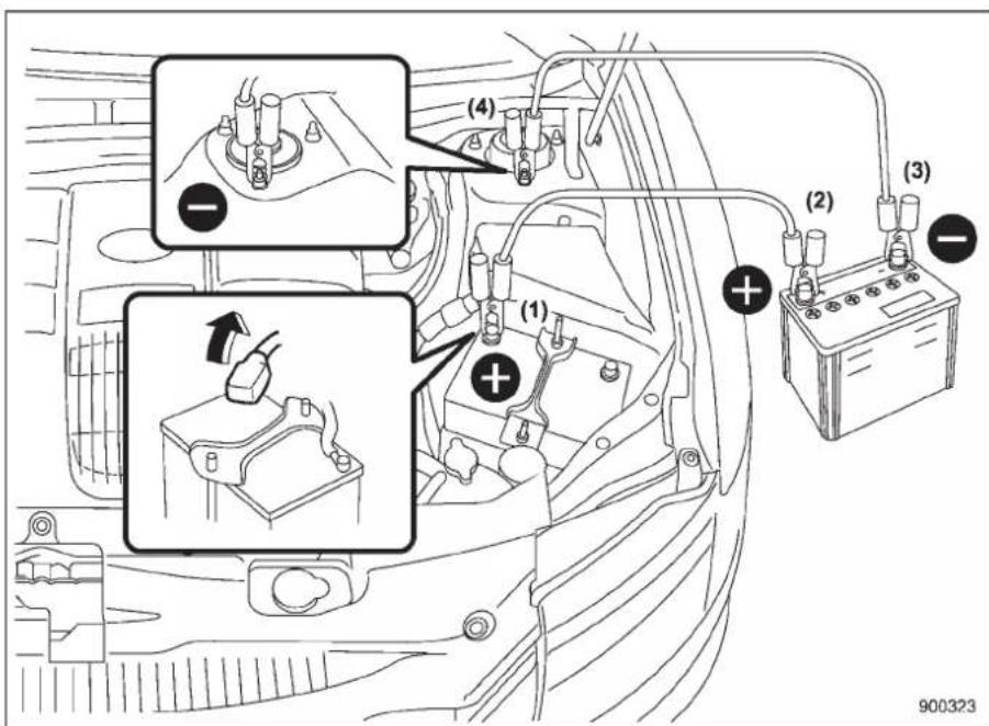
(1) Connectonejumpercabletothe positive(+)terminalonthedischarged battery.
(2)Connecttheotherendofthe jumpercabletothepositive(+)terminaloftheboosterbattery.
(3) Connectoneendoftheother cabletothenegative(-)terminal of theboosterbattery.
(4)Connecttheotherendofthecable tothestrutmountingnut.
Makesurethatthecablesarenotnear anymovingpartsandthatthecable clampsarenotincontactwithanyother metal.
-
Starttheengineofthevehiclewiththe boosterbatteryandrunitatmoderate speed. Thenstarttheengineofthevehicle thatasthedischargedbattery.
-
When finished, carefully disconnect the cables in exactly thereverse order.
9-14 Incaseofemergency
Engineoverheating

WARNING
Neverattempttoremovetheradiatorcapuntiltheenginehasbeen shutoffandhasfullycooleddown. Whentheengineishot, thecoolant isunderpressure.Removingthe capwhiletheengineisstillhot couldreleaseasprayofboilinghot coolant, whichcouldburnyouvery seriously.
Iftheengineoverheats,safelypulloffthe roadandstopthevehicleinasafeplace.
■ Ifsteamiscomingfromthe enginecompartment
Turnofftheengineandgeteveryone awayfromthevehicleuntilitcoolsdown.
■ Ifnosteamiscomingfrom theenginecompartment
- Keep the enginerunning at idling speed.
- Open the hood to ventilate the engine compartment. Confirm that the cooling fan is turning. If the fan is not turning, immediately turn off
theengineandcontactyourauthorized dealerforrepair.
- After the engine coolant temperature has dropped, turn off the engine.
If the temperature gaugestays at the overheated zone, turn off the engine.
- After the engine has fully cooled down, check the coolant level in the reserve tank.
If the coolant level is below the "LOW" mark, add coolant upto the "FULL" mark.
- If there is nocoolant in thereserve tank, add coolant to thereservetank. Then removether radiator cap and fill the radiator with coolant.
If you removetheradiatorcap from a hot radiator, first wrapathick cloth around the radiator cap, then turn the cap counterclock wises slowly without pressing down until stops. Re leasethe pressure from theradiator. After the pressure has been fully released, removethe cap by pressing down and turning it.
Towing

WARNING
NevertowAWDmodelswiththe frontwheelsraisedofftheground whiletherearwheelsareonthe ground,orwiththerearwheels raisedoffthegroundwhilethefront wheelsareontheground.Thiswill causethevehicletospinawaydue totheoperationordeteriorationof thecenterdifferential.
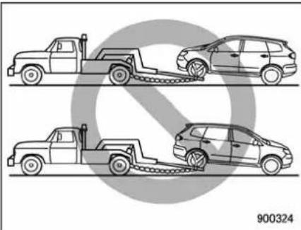
natural_image
Four cartoon-style vehicles on a road with chains, no text or symbols presentIftowingisnecessary,itisbestdoneby yourSUBARUdealeroracommercial towing service. Observe the following proceduresforsafety.
■Towingandtie-downhooks
Thetowinghooksshouldbeusedonlyin anemergency(e.g.,tofreeeastuckvehicle frommud,sandorsnow).

CAUTION
- Useonlythespecifiedtowing hooksandtie-downhooks.Never usesuspensionpartsorother partsofthebodyfortowingor tie-downpurposes.
- Neverusethetie-downhook closesttothemufflerunderthe vehiclefortowingpurposes.
- Topreventdeformationtothe bumperandthetowinghook,do notapplyexcessivelateralload tothetowinghooks.
Fronttowinghook:
- Takeoutthetowinghook, screwdriver and wheelnutwrench from the toolbag.
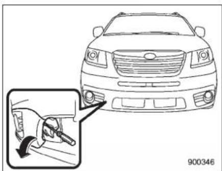
natural_image
Line drawing of a car front view with a magnified inset showing the engine brush applying material to the dashboard (no text or symbols)- Wrapaflat-headscrewdriverinvinyl tapeorcloth, insertitintothegapbetween thecoverandthefrontbumper, and useit toprythecoveropen.
NOTE
●Thecoverisattachedtothefront bumperwithfivelugs.
- Donotremovethecoverwhile holdingtheslit.
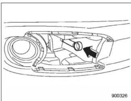
natural_image
Technical line drawing of a mechanical component with no visible text or symbols- Screwthetowinghookintothethread holeuntilthethreadscannolongerbe seen.
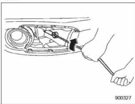
natural_image
Line drawing of a hand using a tool to adjust or install a mechanical component (no text or symbols visible)- Tightenthetowinghooksecurely usingajackhandle.
-CONTINUED-
9-16 Incaseofemergency
Aftertowing, removethetowinghookfrom thevehicleandstowitinthetoolbag. Fitthetowinghookcoveronthebumper.

WARNING
- Donotusethetowinghook exceptwhentowingyourvehicle.
- Besuretoremovethetowing hookaftertowing.Leavingthe towinghookmountedonthe vehiclecouldinterferewithproperoperationoftheSRSairbag systeminafrontalcollision.
Reartowinghook:
- Takeoutthetowinghook, screwdriver and wheelnutwrench from the onboard toolbag.
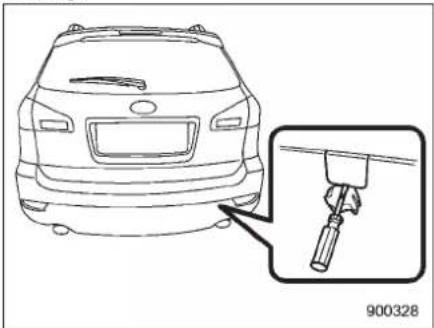
natural_image
Line drawing of a car rear view with an inset showing a tool inserted into the windshield (no text or symbols)- Pry off the cover on the rear bumper using a screwdriver, and you will find a threadedholeforattachingthetowing hook.
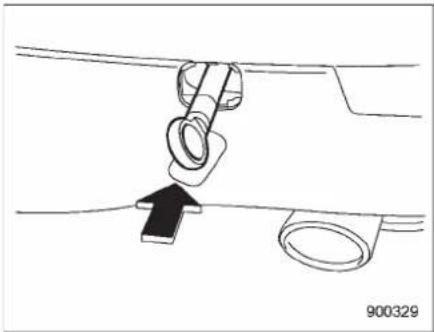
natural_image
Diagram showing a mechanical component being lifted by a hook, with an arrow indicating direction (no text or symbols present)- Screwthetowinghookintothethread holeuntilitsthreadcannolongerbeseen.
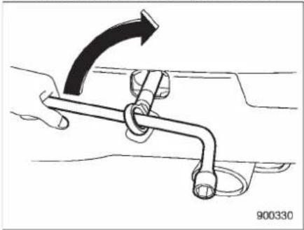
natural_image
Diagram of a mechanical clamp or spring mechanism with an arrow indicating rotation (no text or symbols present)- Tightenthetowinghooksecurely usingawheelnutwrench.
Aftertowing,removethetowinghookfrom thevehicleandstowitinthetoolbag. Putthethreadholecoverontherear bumper.

WARNING
- Donotusethetowinghook exceptwhentowingyourvehicle.
- Besuretoremovethetowing hookaftertowing.Leavingthe towinghookmountedonthe vehiclecouldinterferewithproperoperationoftheSRSairbag systeminafrontalcollision.
Fronttie-downhooks:
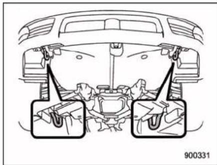
natural_image
Top-down diagram of a car's rear suspension system showing engine, dashboard, and wheel components (no text or labels)Thefronttie-downhooksarelocated betweeneachofthefronttiresandthe frontbumper.
Reartie-downhooks:
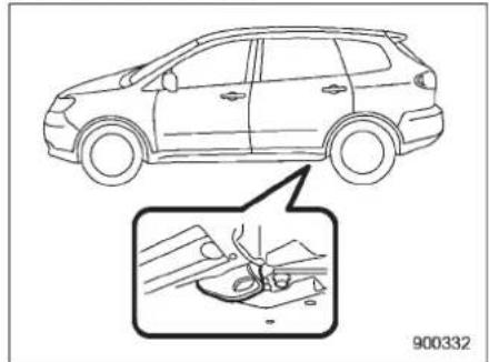
natural_image
Line drawing of a car showing the side profile and a close-up of the engine compartment (no text or symbols)Thereartie-downhooksarelocatednear eachofthejack-upreinforcements.

WARNING
Usethereartie-downhooksonlyfor downwardanchoring.Iftheyare usedtoanchorthevehicleinany otherdirection,cablesmayslipoff thehooks,possiblycausingadangeroussituation.
Usingaflat-bedtruck
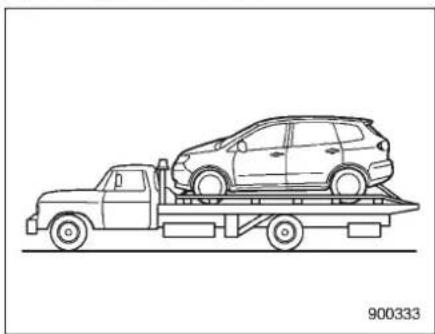
natural_image
Line drawing of a flatbed truck carrying a car on its roof, no text or symbols presentThis is the best way to transport your vehicle. Use the following procedure to ensure safety transportation.
- Shifttheselectleverintothe "P" position.
2.Presstheparkingbrakepedalfirmly. - Secure the vehicle onto the carrier properly with safety chains. Each safety chain should be equally tightened and care must be taken to top all the chains so tightly that the suspension bottomsout.
■ Towingwithallwheelsonthe ground
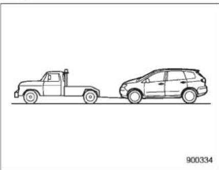
natural_image
Line drawing of two vehicles, one on a flat surface and the other parked on a road (no text or symbols)
WARNING
- Neverturntheignitionswitchto the"LOCK"positionwhilethe vehicleisbeingtowedbecause thesteeringwheelandthedirectionofthewheelswillbelocked.
- Rememberthatthebrakebooster andpowersteeringdonotfunctionwhentheengineisnot running.Becausetheengineis turnedoff,itwilltakegreater effortto operate the brakepedal andsteeringwheel.
-CONTINUED-

CAUTION
- If transmission failure occurs, transport your vehicle on a flat-bed truck.
- Donotruntheenginewhilebeing towedusingthismethod.Transmissiondamagecouldresultif thevehicleistowedwiththe engineerunning.
-
The travelingspeed must be limited to less than 20 mph (30 km/h) and the traveling distance to less than 31 miles (50 km). For greater speeds and distances, transport your vehicle on a flat-bed truck.
-
Check the transmission and differential oil levels and add oil to bring it to the upper level if necessary.
- Releasetheparkingbrakeandputthe transmissioninneutral.
- Theignitionswitchshouldbeinthe "Acc"positionwhilethevehicleisbeing towed.
- Takeupslackinthetowlineslowlyto preventdamagetothevehicle.
Reargate-ifthereargate cannotbeunlocked
Intheeventthatyoucannotunlockthe reargate byoperating thepower door lockingswitchesor theremotekeyless entrysystem,youcanunlockitfrominside thecargoarea.
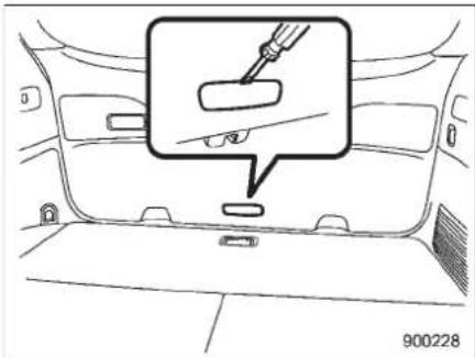
- Removetheaccesscoveratthe bottom-centerofthereargatetrimusing flat-headscrewdriver.
- Locatethereargatelockreleaselever behindthereargatetrimpanel.
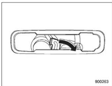
natural_image
Cross-sectional diagram of a mechanical component with internal channels and housing (no text or symbols)- Unlockthereargatebymovingthe levertotheright.
- Openthereargatefromoutsideby raisingthereargatehandle.
Maintenancetools
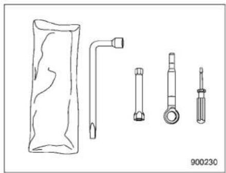
natural_image
Line drawings of mechanical components including a cylindrical part, flanged pipe, and four different screw-like parts (no text or symbols)Your vehicle is equipped with the following maintenance tools.
Screwdriver
Towinghook(eyebolt)
Wheelnutwrench
Extension
Jackandjackhandle
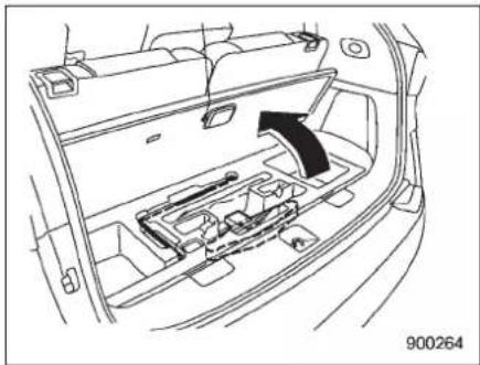
natural_image
Diagram of a car interior showing internal compartments and a directional arrow (no text or symbols)7-seatermodels
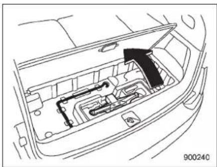
natural_image
Diagram of a car interior showing engine compartment with an arrow indicating direction (no text or symbols)5-seatermodels
Thejackandjackhandleisstoredunder thecargoarea.
Forhowtousethejack, referto "Flattires" 9-6.
| -1.5 | -1.5 | -1.5 | -1.5 |
Appearancecare
Exteriorcare....10-2
Washing....10-2
Waxingandpolishing....10-3
Cleaningaluminumwheels....10-3
Corrosionprotection....10-4
Mostcommoncausesofcorrosion....10-4
Tohelppreventcorrosion....10-4
Cleaningtheinterior....10-5
Seatfabric....10-5
Leatherseatmaterials....10-5
Syntheticleatherupholstery....10-5
Climatecontrol panel, audiopanel, instrument panel, console panel, switches, combination meter, and other plastics surface....10-5
Navigationmonitor(ifequipped)....10-6
10-2 Appearancecare
Exteriorcare
Washing

CAUTION
- When washing the vehicle, the brakes may get wet. As a result, the brake stopping distance will be longer. Todry the brakes, driv the vehicle at as a fespeed while lightly pressing the brake pedal to heat up the brakes.
- Donotwashtheenginecompartmentandareasadjacenttoit.If waterenterstheengineairintake,electricalpartsorthepower steeringfluidreservoir,itwill causeenginetroubleoramal-functionofthepowersteering.
- Sinceyourvehicleisequipped witharearwiper,automaticcarwashbrushscouldbecome tangledaroundit,damagingthe wiperarmandothercomponents.Askth automaticcarwashoperatornottoletthe brushestouchthewiperarmor tofixthewiperarmontherear windowglasswithadhesivetape beforeoperatingthemachine.
NOTE
Whenhavingyourvehiclewashedin anautomaticcarwash,makesure beforehandthatthecarwashisof suitabletype.
The best way top reserve your vehicle's beauty is frequent washing. Wash the vehicle at least once a month to avoid contamination by road grime.
Washdirtoffwithawetspongeandplenty oflukewarmorcoldwater.Donotwash thevehiclewithhotwaterandindirect sunlight.
Salt, chemicals, insects, tar, soot, tree sap, and bird droppings should be washed off by using alight detergent, as required. If you use alight detergent, make certain that it is an unneutral detergent. Donot use
strongsoaporchemicaldetergents.All cleaning agents should be promptly flushed from the surface and not allowed to dry there. Rinsethe vehicle thoroughly with plenty of flukewarm water. Wipethe remaining water off with achamoisor soft cloth.
▼Washingtheunderbody
Chemicals, salts and gravel used for deicing roads surfaces are extremely corrosive, accelerating the corrosion of underbody components, such as the exhaust system, fuel and brakelines, brake cables, floorpan and fenders, and suspension.
Thoroughlyflushtheunderbodyandin-sideofthefenderswithlukewarmorcold wateratfrequentintervalstoreducethe harmfuleffectsofsuchagents.
Mudandsandadheringtotheunderbody componentsmayacceleratetheircorrosion.
Afterdrivingoff-roadormuddyorsandy roads, washthemudandsandoffthe underbody.
Carefullyflushthesuspensionandaxle parts,astheyareparticularlyproneto mudandsandbuildup.Donotusea sharp-edgedtooltoremovecakedmud.
NOTE
Becarefulnottodamagebrakehoses, sensorharnesses, and other parts when washingsuspension components.
▼Usingawarmwaterwasher
- Keepagoodistanceof12in(30cm)ormorebetweenthewashernozzleandthevehicle.
- Donotwashthesameareacontinuously.
- lfastainwillnotcomeouteasily, wash byhand. Somewarmwaterwashers are of the hightemperature, high pressure type, and they can damage or deform the resin part such as mouldings, or cause watertoleak into the vehicle.
Waxingandpolishing
Alwayswashanddrythevehiclebefore waxingandpolishing.
Useagoodqualitypolishandwaxand applythemaccordingtothemanufac-turer'sinstructions. Waxor polishwhen thepaintedsurfaceiscool.
Be sure to polish and wax the chrome trim, aswellasthepaintedsurfaces.Lossof waxonapaintedsurfaceleadstolossof theoriginallusterandalsoquickensthe deteriorationofthesurface.Itisrecom-
mendedthatacoatofwaxbeappliedat leastonceamonth,orwheneverthe surfacenolongerrepelswater.
If the appearance of the painthas diminished to the point where the lusterortone cannot be restored, lightly polish the surface with a fine-grained compound. Never polish just the affected area, but includethes surrounding area as well. Always polish in only one direction. A No. 2000 grain compound is recommended. Never use a coarse-grained compound. Coarser grained compounds have as smaller grain-sizenumber and could damage the paint. After polishing with a compound, coat with wax to restore the original cluster. Frequent polishing with a compound or an incorrect polishing technique will result in removing the paint layer and exposing the undercoat. When indoubt, it is always best to contact your SUBARU dealerorana autopaints specialist.
NOTE
Becarefulnottoblockthewindshield washernozzleswithwaxwhenwaxing thevehicle.
■Cleaningaluminumwheels
- Promptlywipethealuminumwheels cleanofanykindofgrimeoragent. If dirt is left to tool long, it may be difficult to clean off.
- Donotusesoapcontaininggritto clean the wheels. Be sure to use a neutral cleaningagent, and laterrinsethoroughly with water. Donotclean thewheelswitha stiff brush or expose them to a high-speed washingdevice.
- Cleanthevehicle(includingthealuminumwheels)withwaterassoonas possiblewhenithasbeensplashedwith sea water, exposed to sea breezes, or drivenonroadstreatedwithsaltorother agents.
10-4 Appearancecare
Corrosionprotection
YourSUBARUhasbeendesignedand builttoresistcorrosion.Specialmaterials andprotectivefinisheshavebeenusedon mostpartsofthevehicletohelpmaintain fineappearance,strength,andreliable operation.
■Mostcommoncausesof corrosion
Themostcommoncausesofcorrosion are:
- The accumulation of moisturizer retaining dirt and debris in body panel sections, cavities, and other areas.
- Damagetopaintandotherprotective coatingscausedbygravelandstone chipsorminoraccidents.
Corrosionisacceleratedonthevehicle when:
- It is exposed to roads salt or dust control chemicals, or used in coastal areas where there is more salt in the air, or in areas where there is considerable industrial pollution.
- It is driven in areas of high humidity, especially when temperatures range just above freezing.
- Dampness incertain part of the vehicleremains for along time, even
though other part of the vehicle maybe dry.
- High temperatures will cause corrosion topartsofthevehiclewhich cannot dryquicklyduetolackofproperventilation.
■ Tohelppreventcorrosion
Washthevehicleregularlytoprevent corrosionofthebodyandsuspension components. Also, washthevehicle promptlyafterdrivingonanyofthe followingsurfaces.
- roadsthathavebeensaltedtoprevent themfromfreezinginwinter
- mud,sand,orgravel
- coastalroads
Afterthewinterhasended,itisrecommendedthattheunderbodybegivena verythoroughwashing.
Beforethebeginningofwinter,checkthe conditionofunderbodycomponents,such astheexhaustsystem,fuelandbrake lines,brakecables,suspension,steering system,floorpan,andfenders.Ifanyof themarefoundtoberusted,theyshould begivenanappropriaterustprevention treatmentshouldbereplaced.Contact yourSUBARUdealertoperformthiskind ofmaintenanceandtreatmentifyouneed
assistance.
Repairchipsandscratchesinthepaintas soonasyoufindthem.
Checktheinteriorofthevehicleforwater anddirtaccumulationunderthefloormats becausethatcouldcausecorrosion. Occasionallycheckunderthematsto makesuretheareaisdry.
Keepyourgaragedry.Donotparkyour vehicleinadamp,poorlyventilated garage.Insuchagarage,corrosioncan becausedbydampness.Ifyouwashthe vehicleinthegarageorputthevehicle intothegaragewhenwetorcoveredwith snow,thatcancausedampness.
If your vehicle is operated in cold weather and/orin areas whereroadsalts and other corrosiv materials are used, the door hinges and locks, and hoodlatch should be inspected and lubricated periodically.
Cleaningtheinterior
Useasoft,dampclothocleantheclimate controlpanel,audioequipment,instrumentpanel,centerconsole,combination meterpanel,andswitches.(Donotuse organicsolvents.)
Seatfabric
Removeloosedirt, dustordebriswitha vacuumcleaner. If the dirtiscaked on the fabricorhardtoremovewithavacuum cleaner, use asoftblushthenvacuumit.
Wipethefabricsurfacewithatightly wrungclothanddrytheseatfabric thoroughly. If the fabric is still dirty, wipe using asolution of mild soap and lukewarm waterthendrythoroughly.
Ifthestaindoesnotcomeout,trya commercially-availablefabriccleaner.Use thecleaneronahiddenplaceandmake sureitdoesnotaffectthefabricadversely. Use thecleaneraccordingtoitsinstructions.
NOTE
Whencleaningtheseat, donotuse benzine, paintthinner, oranysimilar materials.
Leatherseatmaterials
TheleatherusedbySUBARUisahigh qualitynaturalproductwhichwillretainits distinctiveappearanceandfeelformany yearswithpropercare.
Allowingdustorroaddirttobuilduponthe surfacecancausethematerialtobecome brittleandtowearprematurely. Regular cleaningwithasoft,moist,naturalfiber clothshouldbeperformedmonthly,taking carenottosoaktheleatherorallowwater topenetratethestitchedseams.
Amilddetergentsuitableforcleaning woolenfabricsmaybeusedtoremove difficultdirtspots, rubbingwithasoft,dry clothafterwardstorestoretheluster. If your SUBARUistobeparkedforalong timeinbrightsunlight,itisrecommended thattheseatsandheadrestsbecovered, orthewindowssshaded,topreventfading orshrinkage.
Minorsurfaceblemishesorbaldpatches maybetreatedwithacommercialleather spraylacquer. Youwilldiscoverthateach leatherseatsectionwilldevelopsoftfolds orwrinkles,whichischaracteristicof genuineleather.
■Syntheticleatherupholstery
Thesyntheticleathermaterialusedonthe SUBARUmaybecleanedusingmildsoap
ordetergentandwater,afterfirstvacuum-ingorbrushingawayloosedirt.Allowthe soaptosoakinforafewminutesandwipe offwithaclean,dampcloth.Commercial foam-typecleanerssuitableforsynthetic leathermaterialsmaybeusedwhen necessary.
NOTE
Strongcleaningagentssuchassolvents, paintthinners, windowcleaner orgasolinemustneverbeusedon leatherorsyntheticinteriormaterials.
■Climatecontrolpanel,audio panel,instrumentpanel,consolepanel,switches, combinationmeter,andother plasticsurface
Useasoft,dampclothocleantheclimate controlpanel,audioequipment,instrumentpanel,centerconsole,combination meterpanel,andswitches.
NOTE
Donotuseorganicsolventssuchas paintthinnersorgasoline,orstrong cleaningagentsthatcontainthose solvents.
10-6 Appearancecare
■Navigationmonitor(if equipped)
Tocleanthenavigationmonitor,wipeit withasiliconeclothorwithasoftcloth.If thenavigationmonitorisextremelydirty, cleanitwithasoftclothmoistenedwith neutraldetergentthencarefullywipeoff anyremainingdetergent.
NOTE
- Donotsprayneutraldetergentdirectlyontothemonitor.Doingsocould damagethemonitor'scomponents.
- Donotwipethemonitorwithahard cloth.Doingsocouldscratchhe monitor.
- Donotusecleaningfluidthatcontains thinner, gasoline, or any other volatilesubstance.Suchcleaningfluid could erase the lettering on the switchesatthebottomofthemonitor.
Maintenance and service
Maintenanceschedule....11-3
Maintenance precautions....11-3
Beforecheckingorservicingintheengine compartment....11-4
When you do checking or servicing in the engine compartment while the engine is running.....11-4
Enginehood....11-4
Enginecompartmentoverview....11-6
Engineoil....11-7
Checkingtheoillevel....11-7
Changingtheoilandoilfilter....11-8
Recommendedgradeandviscosity....11-9
Recommendedgradeandviscosityunder severedrivingconditions....11-10
Coolingsystem....11-11
Hoseandconnections....11-11
Enginecoolant....11-11
Aircleanerelement....11-14
Replacingtheaircleanerelement....11-14
Sparkplugs....11-15
Recommendedsparkplugs....11-15
Drivebelts....11-15
Automatictransmissionfluid....11-16
Checkingthefluidlevel....11-16
Recommendedfluid....11-17
Frontdifferentialgearoil....11-17
Checkingtheoillevel....11-17
Recommendedgradeandviscosity....11-18
Reardifferentialgearoil....11-18
Checkingthegearoillevel....11-18
Recommended grade and viscosity.... 11-19
Powersteeringfluid.... 11-19
Checkingthefluidlevel.... 11-19
Recommended fluid 11-20
Brake fluid 11-20
Checkingthefluidlevel.... 11-20
Recommendedbrakefluid.... 11-21
Brake booster 11-21
Brake pedal 11-22
Checkingthebrakepedalfreeplay.... 11-22
Checkingthebrakepedalreservedistance...... 11-22
Replacementofbrakepadandlining.... 11-22
Breaking-inofnewbrakepadsandlinings..... 11-23
Parking brake stroke 11-23
Tiresandwheels.... 11-24
Types of tires.... 11-24
Tirepressuremonitoringsystem(TPMS)...... 11-24
Tireinspection....11-25
Tirepressuresandwear.... 11-26
Wheel balance 11-28
Wear indicators 11-28
Tire rotation direction mark.... 11-28
Tire rotation.... 11-29
Tirereplacement.... 11-29
Wheelreplacement.... 11-30
Aluminumwheels.... 11-30
Chromeplatedwheels(ifequipped).... 11-31
Windshieldwasherfluid.... 11-32
Replacementofwiperblades.... 11-33
Windshieldwiperbladeassembly.... 11-34
Maintenance and service
Windshieldwiperbladerubber....11-34
Rearwindowwiperbladeassembly....11-35
Rearwindowwiperbladerubber....11-35
Battery.... 11-37
Fuses....11-38
Mainfuse....11-39
Installationofaccessories....11-40
Replacingbulbs....11-40
Headlights(modelswithHIDheadlights)......11-40
Headlights(modelswithoutHIDheadlights).....11-40
Parkinglight(right-handside)....11-42
Frontturnsignallight(right-handside)......11-43
Frontfoglight....11-43
Rearcombinationlights....11-43
Back-uplight/Taillight....11-44
Reargatelight....11-45
Licenseplatelight....11-45
Domelight....11-46
Maplight....11-47
Vanitymirrorlight....11-47
Doorsteplight....11-47
Cargoarealight....11-48
Maintenanceschedule
Thescheduledmaintenanceitemsrequiredtobeservicedatregularintervalsareshowninthe"WarrantyandMaintenanceBooklet".
Fordetailsofyourmaintenanceschedule, readtheseparate"WarrantyandMaintenanceBooklet".
Maintenance precautions
When maintenance and service arerequired, it is recommended that all work be done by an authorized SUBARU dealer.
If you perform maintenance and service by yourself, you should familiarize yourself with the information provided in this section on general maintenance and service for your SUBARU.
Incorrectorincompleteservicecould causeimproperorunsafevehicleoperation. Anyproblemscausedbyimproper maintenanceandserviceperformedby youarenoteligibleforwarrantycoverage.

WARNING
- TestingofanAll-WheelDrive modelmust NEVERbe performedonasingletwo-wheel dynamometerorsimilarapparatus.Attemptingtodosowill resultintransmissiondamage and inuncontrolled vehicle movementandmaycausean accidentorinjuriestopersons nearby.
- Alwaysselectasafeareawhen performingmaintenanceonyour vehicle.
●Alwaysbeverycarefultoavoid injurywhenworkingonthevehicle.Rememberthatsomeofthe materialsinthevehiclemaybe hazardousifimproperlyusedor handled,forexample,battery acid.
- Your vehicle should only be servicedbypersonsfullycompetent todos.Seriouspersonalinjury mayresulttopersonsnotexperiencedinservicingvehicles.
- Always use the proper tools and make certain that they are well maintained.
- Never get under the vehicle supportedonlybyajack.Alwaysuse asafetystandstosupportthe vehicle.
- Neverkeeptheengine running in apoorlyventilated area, such as agarageorotherclosedareas.
- Donotsmokeorallowopen flamesaroundthefuelorbattery. Thiswillcauseafire.
- Because the fuel system is under pressure, replacement of the fuel filters should be performed only by your SUBARU dealer.
- Wear adequate eye protection to
Maintenanceandservice
guardagainstgettingoilorfluids inyoureyes.Ifsomethingdoes getinyoureyes,thoroughly washthemoutwithcleanwater.
- Donottamperwiththewiringof theSRSairbagsystemorseat-beltpretensionersystem,orattempttotakeitsconnectors apart,asthatmayactivatethe systemoritcanrenderitinoperative. NEVERUseacircuit testerforthesewing.Ifyour SRSairbagorseatbeltpretensionerneedsservice,consult yournearestSUBARUdealer.
■ Beforecheckingorservicing intheenginecompartment

WARNING
●Alwaysstoptheengineandset theparkingbrakefirmlytopreventthevehiclefrommoving.
●Alwayslettheenginecooldown. Enginepartsbecomeveryhot whentheengineisrunningand remainhotforsometimeafter theengineisstopped.
- Donotspillengineoil, engine coolant, brakefluidoranyother
fluidonhotenginecomponents. Thismaycauseafire.
●Alwaysremovethekeyfromthe ignitionswitch.Whentheignition switchisinthe"ON"position, the cooling fan may operate suddenlyevenwhentheengine isstopped.
■ Whenyoudocheckingor servicingintheenginecompartmentwhiletheengineis running

WARNING
Arunningenginecanbedangerous. Keepyourfingers,hands,clothing, hairandtoolsawayfromthecooling fan,beltsandanyothermoving engine parts. Removingrings, watchesandtiesisadvisable.
Enginehood
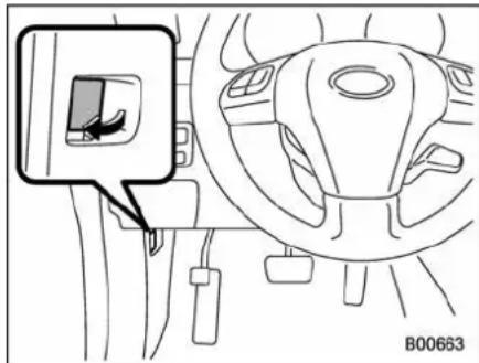
natural_image
Diagram of a car interior showing steering wheel, dashboard, and steering wheel (no text or symbols)Toopenthehood:
- Ifthewiperbladesareliftedoffthe windshield, returnthemtotheiroriginal positions.
- Pullthehoodreleaseknobunderthe instrumentpanel.
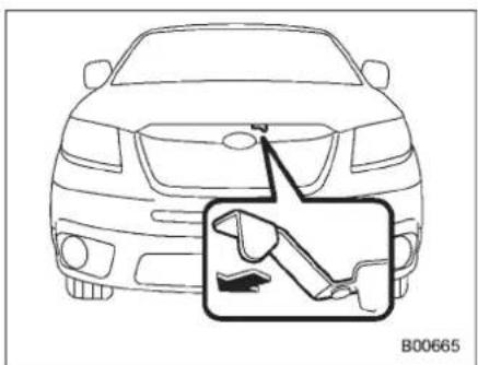
natural_image
Front view of a car with a highlighted side panel showing the wheel and seat (no text or symbols)- Releasethesecondaryhoodrelease locatedunderthefrontgrillebymovingthe levertowardtheleft.
- Liftupthehood.
Toclosethehood:
-
Lowerthehoodtoapointapproximately20in(50cm)fromtheclosed positionandthengivethehoodastrong pushdowntomakeitdrop.
-
Afterclosing the hood, besure the hood is securely locked.
If this does not close the hood, release it from as lightly higher position. Donot push the hood forcibly to close it. It could deform themetal.

WARNING
Always check that the hood is properly locked before you start driving. If it is not, it might fly open while the vehicle is moving and block your view, which may cause an accident and serious bodily injury.

CAUTION
When closing the hood, be careful not topinch your or other person's hands or anything else in the hood.
11-6 Maintenance and service
Enginecompartmentoverview
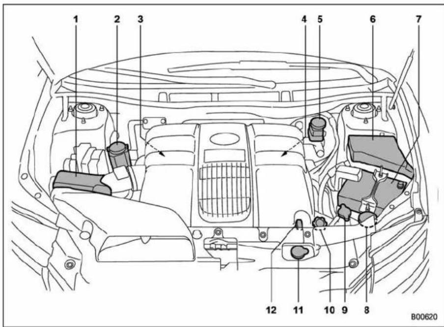
1) Aircleanerelement(page11-14)
2) Powersteeringfluidreservoir (page 11-19)
3) Differential gear oil level gauge (page 11-17)
4) Automatic transmission fluid level gauge (page 11-16)
5)Brakefluidreservoir(page11-20)
6)Fusebox(page11-38)
7)Battery(page11-37)
8)Windshieldwashertank(page11-32)
9)Radiatorcap(page11-11)
10)Engineoilfillercap(page11-7)
11)Enginecoolantreservoir(page11-11)
12)Engineoillevelgauge(page11-7)
Engineoil
NOTE
- Theengineoilconsumptionrateis notstabilized, and therefore cannot be determined until the vehicle has traveled at least several thousand miles (kilometers). Even after break-in, when the vehicle is used under severe driving conditions such as those mentioned in the "Warranty and Maintenance Booklet", engine oil is consumed, deteriorated more quickly than under normal driving conditions. If you drive your vehicle under these severe conditions, you should check the oil level at least every second fuel fill-up time, and change the oil more frequently. Pleasereferto the "Warranty and Maintenance Booklet" formoredetails.
- If the oil consumption rates seems abnormally high after the break-in period, fore example more than 1 quart per 1,200 miles or 1 liter per 2,000 kilometers, were recommend that you contact your SUBARU dealer.
■ Checkingtheoillevel
Checktheengineoillevelateachfuel stop.
- Park the vehicle on a level surface and stoptheengine.
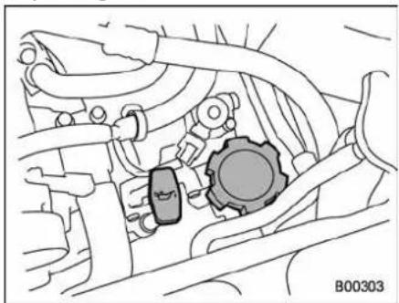
natural_image
Technical diagram of a mechanical assembly with gears and tubing (no text or symbols)-
Pulloutthelevelgauge,wipeitclean, andinsertitagain.
-
Besurethelevelgaugeiscorrectly inserteduntilitstopswiththegraphic symbol" 📋 "onitstopappearingas shownintheillustration.
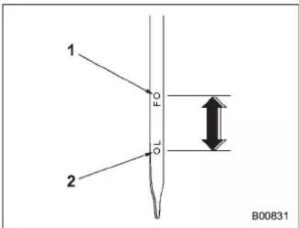
1) Fulllevel
2) Lowlevel
- Pulloutthelevelgaugeagainand checktheoillevelonit.Ifitisbelowthe lowlevel,addoiltobringthelevelupto thefulllevel.

CAUTION
- Useonlyengineoilwiththe recommendedgradeandviscosity.
-CONTINUED-
11-8 Maintenance and service
- Becarefulnottospillengineoil whenaddingit.Ifoiltouchesthe exhaustpipe,itmaycauseabad smell,smoke,and/orafire.If engineoilgetsontheexhaust pipe,besuretowipeitoff.
If you check the oil level just after stopping the engine, wait a few minutes for the oil to drain back into the oil pan before checking the level.
Topreventoverfillingtheengineoil, donot addanyadditionaloilabovethefulllevel whentheengineiscold.
■ Changingtheoilandoilfilter
Changetheoilandoilfilteraccordingto themaintenancescheduleinthe"WarrantyandMaintenanceBooklet".
Theengineoilandoilfiltermustbe changed more frequently than listed in the maintenance schedule when driving ondustyroads,whenshorttripsare frequentlymade,orwhendrivingin extremelycoldwhether.
-
Warm up the engine by letting the engineidleforapproximately10minutes toeasedrainingtheengineoil.
-
Parkthevehicleonalevelsurfaceand stoptheengine.
-
Removetheoilfillercap.
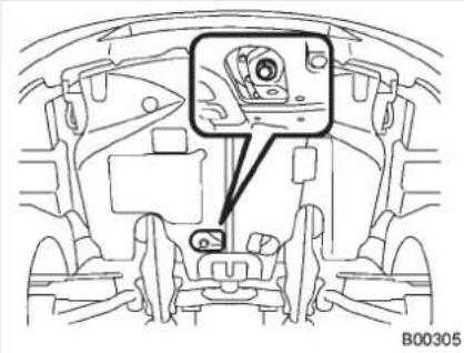
natural_image
Technical line drawing of a car interior showing engine compartment and dashboard (no text or symbols)- Drainouttheengineoilbyremoving the drain plug while the engine is still warm. The used oil should be drained into an appropriate container and disposed of properly.

WARNING
Becarefulnottoburnyourselfwith hotengineoil.
- Wipetheseatingsurfaceofthedrain plugwithacleanclothandtightenit securelywithanewsealingwasherafter theoilhascompletelydrainedout.
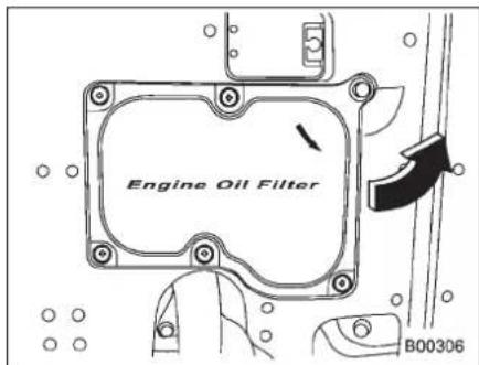
- Open the access cover by removing thefiveclipsandturningtheaccesscover counterclockwise.Theoilfilterwillbe exposed.
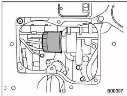
natural_image
Technical diagram of an internal mechanical assembly with no visible text or symbols-
Remove the oil filter with an oil filter wrench.
-
Cleantherubbersealseatingarea of thebottomofengineandinstalltheoil filterbyhandturning.Becarefulnotto twistordamagetheseal.
- Tightentheoilfilterbytheamount indicatedinthefollowingtableafterthe sealmakescontactwiththebottomof engine.
| OilfiltercolorPartnumber | Amountofrotation | |
| Black1520 | 8AA031 | 3/4rotation |

CAUTION
- Neverovertightentheoilfilter because that can result in an oil leak.
-
Thoroughlywipeoffanyengine oilthathasspilledoverthe exhaustpipeand/orunder-cover. Ifleftunremoved,theoilcould catchfire.
-
Reinstall the cover under the oil filter.
- Pourengineoilthroughthefillerneck.
Oilcapacity(guideline):
6.7USqt(6.3liters,5.5Impqt)
Theoilquantityindicatedaboveisonlya guideline. Thenecessaryquantityofoil dependsonthequantityofoilthathas beendrained.Thequantityofdrainedoil differslightlydependingonthetemperatureoftheoilandthetimetheoilisleft flowingout.Afterrefillingtheenginewith oil, therefore, you must use the level gaugetoconfirmthattheleveliscorrect.
- Start the engine and make sure that no oilleaksappeararoundthefilter'srubber sealanddrainplug.
- Runtheengineuntilireachesthe normaloperatingtemperature. Thenstop the engine and wait a few minutes to allow theoildrainback. Check theoillevel againandifnecessary,addmoreengine oil.
■Recommendedgradeand viscosity

CAUTION
Useonlyengineoilwiththerecommendedgradeandviscosity.
Oilgrade:
ILSACGF-4, which can be identified with the ILSAC certification mark (Starburst mark)
orAP classificationSMwiththewords "ENERGYCONSERVING"
Theserecommendedoilgradescanbe identifiedbylookingforeitherorbothof thefollowingmarksdisplayedontheoil container.

B00014
ILSACCertificationMark(StarburstMark)
-CONTINUED-
11-10 Maintenance and service
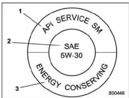
APIServicelabel
1) Indicate the oil quality by API designations
2) Indicate the SAE oil viscosity grade
3) Indicate that the oil has fuel-saving capabilities
Inchoosinganoil,youwanttheproper qualityandviscosity,aswellasonethat willaddtofueleconomy.Thefollowing tableliststherecommendedviscosities andapplicabletemperatures.
Whenaddingoil, differentbrands maybe used together as long as they are the same API classification and SAE viscosity asthose recommended by SUBARU.
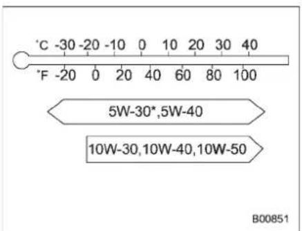
SAEviscositynumberandapplicable temperature
*:5W-30isrecommended.
Engineoilviscosity(thickness)affectsfuel economy.Oilsoflowerviscosityprovide betterfueleconomy.However,inhot weather,oilofhigherviscosityisrequired toproperlylubricatetheengine.
■Recommendedgrade and viscosity underseveredriving conditions
If the vehicle is used in desert areas, in areas with very high temperatures, or used for heavy-duty applications such as towing a trailer, use of oil with the following grade and viscosities is recommended.
APIclassificationSM(orSL):
SAEviscosityNo.:
30,40,10W-50,20W-40,20W-50
Coolingsystem

WARNING
Neverattempttoremovetheradiatorcapuntiltheenginehasbeen shutoff and has cooled down completely. Sincethecoolantis underpressure, youmaysuffer serious burns from aspray of boiling hot coolant when the capis removed.

CAUTION
- Vehiclesarefilledatthefactory withSUBARUSuperCoolantthat doesnotrequirethefirstchange for11years/137,500miles(11 years/220,000km).Thiscoolant shouldnotbe mixed withany otherbrand ortype of coolant duringthisperiod.Mixingwitha differentcoolantwillreducethe lifeofthecoolant.Shouldditbe necessarytotopoffthecoolant for any reason, use only SUBARUSuperCoolant. IftheSUBARUSuperCoolantis dilutedwithanotherbrandor type,themaintenanceintervalis
shortenedtothatofthemixing coolant.
- Donotsplashtheenginecoolant overpaintedparts.Thealcohol containedintheenginecoolant maydamagethepaintsurface.
■Hoseandconnections
Yourvehicle employs an electric cooling fan which is thermostatically controlled to operate when the engine coolant reaches as specific temperature.
Iftheradiatorcoolingfandoesnotoperate evenwhentheenginecoolanttemperaturegaugeexceedsthenormaloperating range, thecoolingfancircuitmaybe defective. Checkthefuseandreplaceit ifnecessary. Ifthefuseisnotblown, have thecoolingsystemcheckedbyyour SUBARUdealer.
Iffrequentadditionofcoolantisnecessary,theremaybealeakintheengine coolingsystem.Itisrecommendedthat thecoolingsystemandconnectionsbe checkedforleaks,damage,orlooseness.
■Enginecoolant
▼Checkingthecoolantlevel
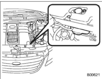
natural_image
Technical diagram of a car engine showing internal components and a close-up view of the hood (no text or symbols present)Check the coolant level at each fuel stop.
- Checkthecoolantlevelontheoutside ofthereservoirwhiletheengineiscool.
- Ifthelevelisclosetoorlowerthanthe "LOW"levelmark,addcoolantuptothe "FULL"levelmark.Ifthereservetankis empty,removetheradiatorcapandrefill asrequired.
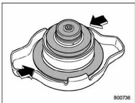
natural_image
Technical diagram of a mechanical component with concentric layers and directional arrows (no text or symbols)- After refilling the reservetank and the radiator, reinstall the caps and check that therubbergaskets inside a radiator cap are in the proper position.

CAUTION
- Becarefulnottospillengine coolantwhenaddingit.Ifcoolant touchestheexhaustpipe,itmay causeabadsmell,smoke,and/or afire.Ifenginecoolantgetson theexhaustpipe,besuretowipe itoff.
- Donotsplashtheenginecoolant overpaintedparts.Thealcohol containedintheenginecoolant maydamagethepaintsurface.
▼Changingthecoolant
AlwaysaddgenuineSUBARUcooling systemconditioner wheneverthe coolant isreplaced.
Changetheenginecoolantandadd genuine SUBARUcoolingsystem conditionerusingthefollowingprocedures accordingtothemaintenanceschedule in the "Warranty and Maintenance Booklet".
- Removetheundercover.
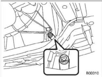
natural_image
Mechanical assembly diagram showing a lever mechanism with a magnified inset of a bolt detail (no text or symbols)-
Place a proper container under the drainplugandloosenthedrainplug.
-
Loosentheradiatorcaptodrainthe coolant from the radiator. Then drain the coolantfromthereservetank.Tightenthe drainplugsecurely.

WARNING
Never attempt toremovetheradiatorcapuntiltheenginehasbeen shutoffandhascooleddown completely.Sincethecoolantis underpressure,youmaysuffer seriousburns froma spray ofboilinghotcoolantwhenthecaps removed.
- Install the undercover.
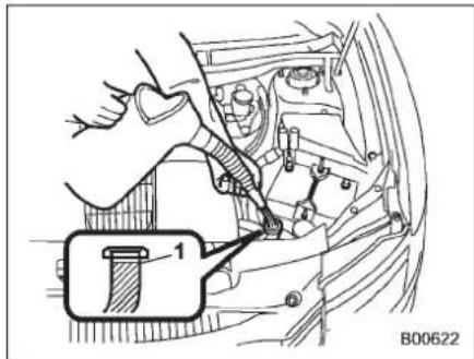
1) Filluptohere
5. Slowly pour the coolant and fill up to
justbelowthefillerneck,allowingenough roomtoaddgenuineSUBARUcooling systemconditionerintheradiator.Add genuineSUBARUcoolingsystemconditioneruntilthecoolantlevelreachesthe fillerneck.Donotpourthecoolanttoo quickly,asthismayleadtoinsufficientair bleedingandtrappedairinthesystem.
Coolantcapacity(guideline): 8.0USqt(7.6liters,6.7Impqt

CAUTION
- Becarefulnottospillengine coolantwhenaddingit.Ifcoolant touchestheexhaustpipe,itmay causeabadsmell,smoke,and/or afire.Ifenginecoolantgetson theexhaustpipe,besuretowipe itoff.
- Donotsplashtheenginecoolant overpaintedparts.Thealcohol containedintheenginecoolant maydamagethepaintsurface.
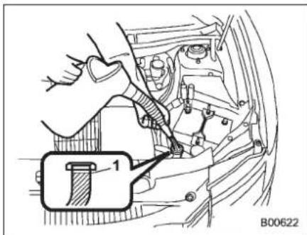
1)"FULL"levelmark
- Pour the coolant and fill to the reservoir tank's "FULL" levelmark.
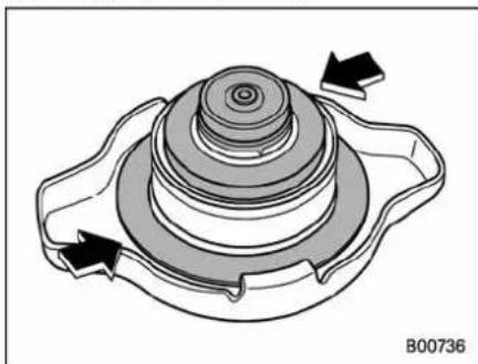
natural_image
Technical diagram of a mechanical component with concentric layers and directional arrows (no text or symbols)- Puttheradiatorcapbackonand tightenfirmly.Atthistime,makesurethat therubbergasketintheradiatorcapis
correctlyinplace.
- Start and race the engine at 2,000 to 3,000 rpm for 5 to 6 times within 40 seconds.
- Stop the engine and wait until the coolant cools down (122 to 140°F [50 to 60°C]). If there is any loss of coolant, add coolant to other radiator's filler neck and to thereservetank's "FULL" level.
- Puttheradiatorcapandreservoircap backonandtightenfirmly.
11-14 Maintenance and service
Aircleanerelement

WARNING
Donotoperatetheenginewiththe aircleanerelementremoved.Theair cleanerelementnotonlyfilters intakeairbutalsostopsflamesif theenginebackfires.Iftheair cleanerelementisnotinstalled whentheenginebackfires,you couldbeburned.

CAUTION
When replacing the air cleanerelement, use a genuine SUBARUair cleanerelement. If it is not used, there is the possibility of causing a negative effect to the engine.
Theaircleanerelementfunctionsasa filterscreen. Whentheelementisperforatedorremoved, enginewearwillbe excessive and engineelifeshortened.
Itisunnecessarytocleanorwashthe element.
■Replacingtheaircleaner element
Replace the air clean element according to the maintenance schedule in the "Warranty and Maintenance Booklet". Under extremely dusty conditions, replace it more frequently. It is recommended that you always use genuine SUBAR uparts.
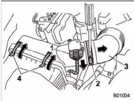
natural_image
Technical line drawing of an engine bay with a hand operating the valve (no text or symbols present)- Opentheaircleanercasecoverand removetheaircleanerelement.
- Clean the inside of the air cleaner case and casecoverwithadampclothand installanewaircleanerelement.
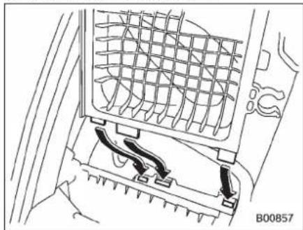
natural_image
Technical line drawing of a car air vent with mesh grille and cooling fins (no text or symbols)- To install the air cleaner case cover, insert the three projections on the air cleaner case cover into the slit on the air cleaner case.
- Installinthereverseorderofremoval.
Sparkplugs
Itmaybedifficulttoreplacethespark plugs.Itisrecommendedthatyouhave the spark plugs replaced by your SUBARUdealer.
Thesparkplugsshouldbereplaced accordingtothemaintenanceschedule inthe"WarrantyandMaintenanceBooklet".
■Recommendedsparkplugs
SILFR6C11(NGK)
Drivebelts
Thealternator, powersteeringpump, and airconditionercompressordependon drivebelts. Satisfactoryperformancerequiresthatbelttensionbecorrect.
Itisunnecessarytocheckbelttension periodically because your engine is equipped with an automatic belt tension adjuster. However, replacement of the belt should be done according to them maintainances schedule in the "Warranty and Maintenance Booklet". Consult your SUBARU dealer for replacement.
Ifabeltisloose,cracked,orworn,contact yourSUBARUdealer.
11-16 Maintenance and service
Automatictransmissionfluid
■ Checkingthefluidlevel
The automatic transmission fluid expands largely as it stemperaturerises; the fluid level differs according to fluid temperature. Therefore, there are two different scales for checking the level of hot fluid and cold fluid on the level gauge.
Though the fluid level can be checked without warming up the fluid on the "COLD" range, were recommend checking the fluid level when the fluid is at operating temperature.
▼ Checkingthefluidlevelwhenthe fluidishot
Checkthefluidlevelmonthly.
- Drivethevehicleseveralmilestoraise the temperature of the transmission fluid uptonormaloperating temperature; 158 to 176°F (70 to 80°C) is normal.
- Parkthevehicleonalevelsurface and settheparkingbrake.
- Firstshift theselectleverineach position. Thenshiftitinthe "P" position, andruntheengineatidlingspeed.
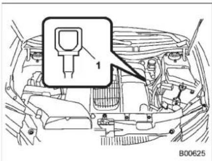
1) Yellowhandle
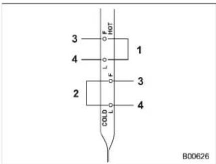
1) HOTrange
2)COLDrange
3) Upperlevel
4) Lowerlevel
- Pullout the level gauge and check the fluid level on the gauge. If it is below the lower level on the "HOT" range, add the recommended automatic transmission fluid up to the upper level.
▼ Checkingthefluidlevelwhenthe fluidiscold
Whenthefluidlevelhastobechecked withouttimetowarmuptheautomatic transmission,checktoseethathefluid levelisbetweenelowerlevelandupper levelonthe"COLD"range.Ifitisbelow thatrange,addfluiduptotheupperlevel. Becarefulnottooverfill.

CAUTION
Becarefulnottospillautomatic transmissionfluid when adding it. If automatictransmissionfluid touches the exhaust pipe, it may causeabadsmell, smoke, and/or a fire. If automatictransmissionfluid getsontheexhaustpipe, besureto wipeitoff.
Recommendedfluid
Useoneofthefollowingtypesofautomatictransmissionfluid.
SUBARUATF
IDEMITSUATFHP
NOTE
Usinganynon-specifiedtypeofautomatictransmissionfluidcouldresultin damageinsidethetransmission.When replacingtheautomatictransmission fluid,besuretouseafluidofthetypes specifiedabove.
Frontdifferentialgearoil
■ Checkingtheoillevel
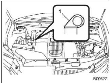
1) Yellowhandle
- Parkthevehicleonalevelsurface and stoptheengine.
- Pulloutthelevelgauge, wipeitclean, andinsertitagain.
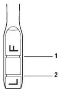
1) Upperlevel
2) Lowerlevel
- Pulloutthelevelgaugeagain and checktheoillevelonit. Ifitisbelow the lowerlevel, addoiltobringthelevelupto theupperlevel.
CAUTION
Becarefulnottospillfrontdifferentialgearoilwhenaddingit.Ifoil touchestheexhaustpipe,itmay causeabadsmell,smoke,and/ora fire.Ifoilgetsontheexhaustpipe, besuretowipeitoff.
11-18 Maintenance and service
■Recommendedgradeand viscosity
Eachoilmanufacturerhasitsownbase oilsandadditives.Neverusedifferent brandstogether.
Oilgrade:
APIclassificationGL-5
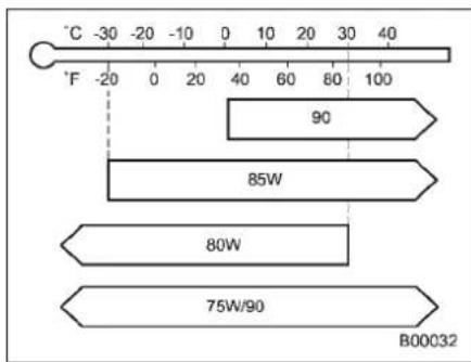
SAEviscosityNo.andapplicabletemperature
Reardifferentialgearoil
■ Checkingthegearoillevel
Your vehicle may be equipped with a rear differential protector. The differential protector provides protection to therear differential assembly during off-road use. Removal of there are differential protector is not required when checking the oil level.
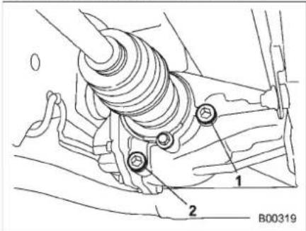
1)Fillerplug
2)Drainplug
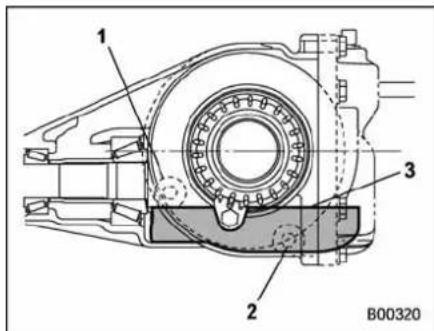
1)Fillerhole
2)Drainhole
3)Oillevel
Removetheplugfromthefillerhole and checktheoillevel. Theoillevelshouldbe keptevenwiththebottomofthefillerhole. Iftheoillevelisbelowthebottomedge of thehole,addoilthroughthefillerholeto raisethelevel.

CAUTION
- Becarefulnottospillreardifferentialgearoilwhenaddingit.If reardifferentialgearoiltouches theexhaustpipe,itmaycausea badsmell,smoke,and/orafire.If reardifferentialgearoilgetson theexhaustpipe,besuretowipe
itoff.
- If the vehiclerequires frequent refilling, theremaybean oilleak. If you suspect a problem, have the vehicle checked at your SUBARU dealer.
■Recommendedgradeand viscosity
Eachoilmanufacturerhasitsownbase oilsandadditives. Neverusedifferent brandstogether.
Oilgrade:
APIclassificationGL-5
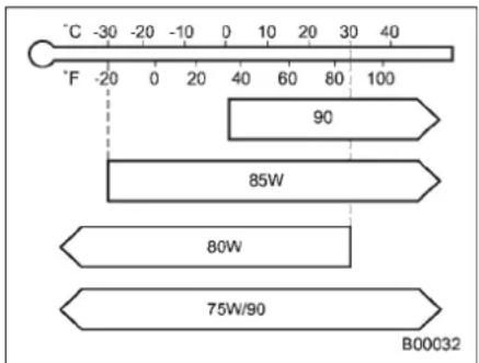
SAEviscosityNo.andapplicabletemperature
Powersteeringfluid
■ Checkingthefluidlevel
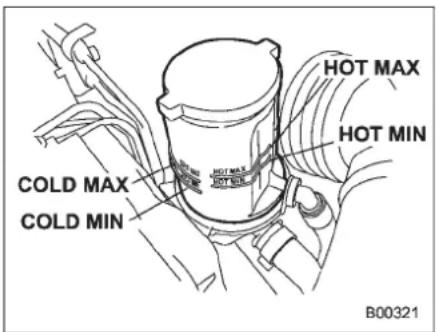

WARNING
Becarefulnottoburnyourself becausethefluidmaybehot.

CAUTION
- Whenpowersteeringfluidis beingadded, useonlycleanfluid, and be careful not to allow any dirt into the tank. And never use different brand together.
- Avoidspillingfluidwhenadding itinthetank.
-CONTINUED-
11-20 Maintenance and service
- Becarefulnottospillpower steeringfluidwhenaddingit.If powersteeringfluidtouchesthe exhaustpipe,itmaycauseabad smell,smoke,and/orafire.If powersteeringfluidgetsonthe exhaustpipe,besuretowipeit off.
The power steering fluid expand greatly as it temperature arises; the fluid level differs according to fluid temperature. Therefore, there is a reservoir tank that two different checking ranges for hot and cold fluids.
Check the power steering fluid level monthly.
-
Parkthevehicleon alevel surface, andstoptheengine.
-
Check the fluid level of the reservoir tank.
Whenthefluidishotafterthevehiclehas beenrun:Checkthattheoillevelis between "HOT MIN" and "HOT MAX" on thesurfaceofthereservoirtank.
When the fluid is cool before the vehicle is run: Check that the oil level is between "COLD MIN" and "COLD MAX" on the surface of the reservoir tank.
- If the fluid level is slower than the applicable "MIN" line, add therecom-
mendedfluid asnecessary to bring the level between the "MIN" and "MAX" line. If the fluid level is extreme low, it may indicate possible leakage. Consult your SUBARU dealer for inspection.
■Recommendedfluid
Useoneofthefollowingtypesofautomatictransmissionfluid.
SUBARUATF
IDEMITSUATFHP
"DexronIII"TypeAutomaticTransmissionFluid
Brakefluid
■ Checkingthefluidlevel
WARNING
- Never letbrakefluidcontactyour eyesbecausebrakefluidcanbe harmfultoyoureyes.Ifbrake fluidgetsinyoureyes,immediatelyflushthemthoroughlywith cleanwater.Forsafety,when performingthiswork,wearing eyeprotectionisadvisable.
●Brakefluidabsorbsmoisture from the air. Any absorbed moisturecancauseadangerousloss ofbrakingperformance.
- If the vehiclerequires frequent refilling, theremaybealeak. If you suspect a problem, have the vehicle checked at your SUBARU dealer.
CAUTION
- When adding brake fluid, be careful not to allow any dirt into the reservoir.
- Neversplashthebrakefluidover paintedsurfacesorrubberparts.
Alcoholcontainedinthebrake fluidmaydamagethem.
- Becarefulnottospillbrakefluid whenaddingit.lfbrakefluid touchestheexhaustpipe,itmay causeabadsmell,smoke,and/or afire.lfbrakefluidgetsonthe exhaustpipe,besuretowipeit off.
Checkthefluidlevelmonthly.
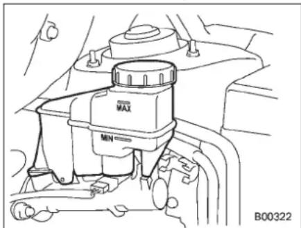
natural_image
Technical line drawing of a mechanical component with labeled parts (MAX, MIN) and B00322 label, no readable text or symbols beyond labels.Checkthefluidlevelontheoutsideofthe reservoir. If the level is below "MIN", add therecommended brakefluid to "MAX". Use only brake fluid from a sealed container.
■Recommendedbrakefluid
FMVSSNo.116, freshDOT3 or DOT4 brakefluid

CAUTION
Neverusedifferentbrandsofbrake fluidtogether. Also, avoidmixing DOT3 and DOT4 brakefluidseven if they are the same brand.
Brakebooster
If the brake booster does not operate as described in the following, have it checked by your SUBARU dealer.
- With the engine off, depress the brake pedalseveraltimes, applying the same pedal force each time. The distance the pedal travel should not vary.
- With the brake pedal depressed, start the engine. The pedal should move slightly downto the floor.
- With the brake pedal depressed, stop the engine and keep the pedal depressed for 30 seconds. The pedal height should not change.
- Starttheengineagainandrunfor approximately1minutethenturnitoff. Depressthebrakepedalseveraltimesto checkthebrakebooster. Thebrake boosteroperatesproperlyifthepedal strokedecreaseswitheachdepression.
11-22 Maintenance and service
Brakepedal
Checkthebrakepedalfreeplayand reservedistanceaccordingtothemaintenancescheduleinthe"Warrantyand MaintenanceBooklet".
■ Checkingthebrakepedal freeplay
natural_image
Pure technical line drawing of a mechanical component with no text or symbols1)0.02-0.08in(0.5-2.0mm)
Stoptheengineandfirmlydepress the brakepedalseveraltimes.Lightlypullthe brakepedalupwithonefingertocheck thefreeplaywithaforceoflessthan2lbf (10N,1kgf). Ifthefreeplayisnotwithinproper specification,contactyourSUBARUdealer.
■ Checkingthebrakepedal reservedistance
natural_image
Anatomical diagram of a foot and ankle joint with measurement annotation (no text or symbols present)1) Morethan2.16in(55mm)
Depressthepedalwithaforceofapproximately66lbf(294N,30kgf)andmeasure thedistancebetweentheuppersurface of thepedalpadandthefloor.
Whenthemeasurementissmallerthan thespecification,orwhenthepedaldoes notoperatesmoothly,contactwithyour SUBARUdealer.
Replacementofbrakepad andlining

CAUTION
If you continuetodrivedespitethe scrapingnoisefromtheaudible brakepadwearindicator, it will resultintheneedforcostlybrake rotorrepairorreplacement.
natural_image
Technical line drawing of a mechanical component with internal components and a bolted joint (no text or symbols)Thefrontdiscbrakeandtherightreardisc brakehaveaudiblewearindicatorsonthe brakepads.Ifthebrakepadswearclose totheirservicelimit,thewearindicator makesaveryaudiblescrapingnoise whenthebrakepedalisapplied.
If you hear this scraping noise each time
youapplythebrakepedal,havethebrake padsservicedbyyourSUBARUdealeras soonaspossible.
■ Breaking-inofnewbrake padsandlinings
When replacing the brake pador lining, use only genuine SUBAR Uparts. After replacement, then new parts must be broken in as follows.
▼Brakepadandlining
While maintaining as speed of 30 to 40 mph (50 to 65 km/h), step on the brake pedallightly. Repeat this five more times.
▼Parkingbrakelining

WARNING
Asafelocationandsituations should be selected for break-indriving.

CAUTION
Pressingtheparkingbrakepedal tooforcefullymaycausetherear wheelstolock.Toavoidthis,be certaintopressthepedalslowly andgently.
- Drivethevehicleataspeedof approximately 22 mph (35 km/h).
- Depresstheparkingbrakepedal SLOWLYandGENTLY.(Pressingwitha forceofapproximately34lbf[150N,15 kgf].)
- Drivethevehicleforapproximately 220 yards (200 meters) in this condition.
- Wait5 to 10 minutes for the parking braketocooldown. Repeat this procedure.
- Check the parking brakestroke. If the parking brakestroke is out of the specified range, adjust it by turning the adjustment nut located on the parking brake pedal.
Parkingbrakestroke:
5-6notches/67lbf(300N,30kgf)
Parkingbrakestroke
natural_image
Diagram of a car seatbelt mechanism with a curved arrow indicating motion (no text or symbols)Checktheparkingbrakestrokeaccording tothemaintenancescheduleinthe "Warranty and Maintenance Booklet". Whentheparkingbrakeisproperly adjusted,brakingpowerisfullyapplied by depressing the pedal five to six notches gentlybutfirmly(approximately67lbf[300 N,30kgf]).Iftheparkingbrakepedal strokeisnotwithinthespecifiedrange, havethebrakesystemcheckedand adjustedatyourSUBARUdealer.
Tiresandwheels
Typesoftires
Youshouldbefamiliarwithtypeoftires presentonyourvehicle.
▼Allseasontires
Thefactory-installedtiresonyournew vehicleareallseasonontires.
Allseasontiresaredesignedtoprovide anadequatemeasureoftraction, handling and braking performance in year-round driving including snowy and icy road conditions. However all season tires do not offer as much traction performance as winter (snow) tires in heavy or loose snow or on icy roads.
Allseasontiresareidentifiedby"ALL SEASON"and/or"M+S"(Mud&Snow)on thetiresidewall.
▼Summertires
Summertiresarehigh-speedcapability tiresbestsuitedforhighwaydrivingunder dryconditions.
Summertiresareinadequatefordriving onslipperyroadssuchasonsnow-coveredoricyroads.
If you drive your vehicle on snow-covered or icy roads, we strongly recommend the use of winter (snow) tires.
Wheninstallingwintertires,besureto
replaceallfourtires.
▼Winter(snow)tires
Wintertiresarebestsuitedfordrivingon snow-coveredandicyroads. However wintertiresdonotperformaswellas summertiresandallseasontiresonroads otherthansnow-coveredandicyroads.
■Tirepressuremonitoring system(TPMS)
Thetirepressuremonitoringsystempro-videsthedriverwithawarningmessage bysendingasignalfromasensorhatis installedineachwheelwhentirepressure isseverelylow. Thetirepressuremonitoringsystemwillactivateonlywhenthe vehicleisdriven.Also,thissystemmay notreactimmediatelytoasuddendropin tirepressure(forexample,ablow-out causedbyrunningoverasharpobject).
If you adjust the tire pressures in a warm garage and will the drivethe vehicle in cold outside air, resulting drop tire pressures may cause the low tire pressure warning light to illuminate. To avoid this problem when adjusting the tire pressures in a warm garage, inflate the tire resto pressures higher than those shown on the tire placard. Specifically, inflatethem by an extra 1 psi (6.9 kPa, 0.07 kgf/cm ^2 ) for every difference of 10°F (5.6°C) between
thetemperatureinthegarageandthe temperatureoutside.Bywayofexample, thefollowingtableshowstherequiredtire pressuresthatcorrespondtovariousoutsidetemperatureswhenthetemperature inthegarageis60°F(15.6°C).
Standardtirepressures:
Front:33psi(230kPa,2.3kgf/cm ^4 )
Rear:32psi(220kPa,2.2kgf/cm ^4 )
Garagetemperature:60°F(15.6°C)
| Outside temperature | Adjustedpressure [psi(kPa,kgf/cm2)] | |
| Front | Rear | |
| 30°F (-1°C) | 36(250,2.5) | 35(240,2.4) |
| 10°F (-12°C) | 38 (265,2.65) | 37 (255,2.55) |
| -10°F (-23°C) | 40(280,2.8) | 39(270,2.7) |
Ifthelowtirepressurewarninglight illuminateswhenyoudrivethevehiclein coldoutsideairafteradjustingthetire pressuresinawarmgarage,re-adjustthe tirepressuresusingthemethoddescribed above.Then,increasethevehiclespeed toatleast20mph(32km/h)andcheckto seethathelowtirepressurewarninglight turnsoffafewminuteslater.Ifthelowtire pressurewarninglightdoesnotturnoff, thetirepressuremonitoringsystemmay
notbefunctioningnormally.Inthisevent, gotoaSUBARUdealertohavethe systeminspectedassoonaspossible.
While the vehicle is driven, friction between tires and theroad surface causes the tirestowarmup. After illumination of the low tire pressure warning light, any increase in the tire pressures caused by an increase in the outside air temperature or by an increase in the temperature in the tirescan cause the low tire pressure warning light to turn off.
Systemresettingisnecessarywhenthe wheelsarechanged(forexample, a switchtosnowtires)andnewTPMS valvesareinstalledonthenewlyfitted wheels.Havethisworkperformedbya SUBARUdealerfollowingwheelreplacement.
ItmaynotbepossibletoinstallTPMS valveson certain wheelsthatare on the market. Therefore, if you changethe wheels (forexample, as wichtosnow tires), use wheelsthathavethesamepart number as the standard - equipment wheels. Without four operational TPMS valve/sensorsonthewheels, the TPMS will not fully function and the warning light in the instrument panel will illuminate steadily after blinking for approximately on minute.
Whenatireisreplaced,adjustmentsare necessarytoensurecontinuednormal operationofthetirepressuremonitoring system. As with wheel replacement, therefore,youshouldhavetheworkperformed byaSUBARUdealer.

WARNING
Ifthelowtirepressurewarninglight doesnotilluminatebrieflyafterthe ignitionswitchisturnedONorthe lightilluminatessteadilyafterblinkingforapproximatelyoneminute, youshouldhaveyourTirePressure MonitoringSystemcheckedata SUBARUdealerassoonaspossible.
If this light illuminates while driving, never brakes suddenly and keep driving straight ahead while gradually reducing speed. Thenslowly pullofftheroadto as a safe place.
Otherwise an accident involving serious vehicle damage and serious personal injury could occur.
If this light still illuminates while driving after adjusting the tire pressure, atire may have significant damage and a fast leak that causes the tire to lose air rapidly. If you have aflattire, replace it with asparetire
assoonaspossible.
Whenasparetireismountedora wheelrimisreplacedwithoutthe originalpressuresensor/transmitter beingtransferred,thelowtirepressure warninglightwillilluminate steadilyafterblinkingforapproximatelyoneminute. This indicates theTPMSisunabletomonitorall fourroadwheels.Contactyour SUBARUdealerassoonaspossible fortireandsensorreplacementand/orsystemresetting.Ifthelight illuminatessteadilyafterblinking for approximately oneminute, promptlycontactaSUBARUdealer tohavethesysteminspected.
■Tireinspection
Checkonadailybasisthatthetiresare freefromseriousdamage,nails,and stones.Atthesametime,checkthetires forabnormalwear.
Contact your SUBARU dealer immediately if you find any problem.
NOTE
- When the wheels and tires strike curbsoraresubjectedtoharshtreatmentaswhenthevehicleisdrivenona roughsurface,theycansufferdamage
-CONTINUED-
thatcannotbeseenwiththenakedeye. Thistypeofdamagedoesnotbecome evidentuntiltimehaspassed.Trynot todriveovercurbs,potholesoron otherroughsurfaces.lfdoingsois unavoidable,keepthevehicle'sspeed downtoawalkingpaceorless,and approachthecurbsassquarelyas possible.Also,makesurethetiresare notpressedagainststhecurbwhenyou parkthevehicle. •Ifyoufeelunusualvibrationwhile drivingorfinditdifficulttosteeerthe vehicleinastraightline,oneofthe tiresand/orwheelsmaybedamaged. Driveslowlytothenearestauthorized SUBARUdealerandhavethevehicle inspected.
■Tirepressuresandwear
Maintaining the correct tire pressures help to maximize the services and disessential for good running performance. Check and, if necessary, adjust the pressure of each tire (including the spare) at least once a month (fore example, during a fuel stop) and before any long journey.
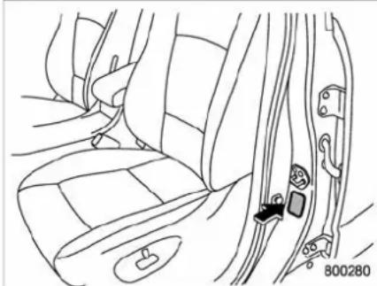
natural_image
Line drawing of a car seatbelt with a hand adjusting the seatbelt (no text or symbols)Check the tire pressures when the tires are cold. Use a pressure gaugetoadjust the tire pressure to the values shown on the tire placard. The tire placard is located on the door pillar on the driver's side.
Driving even short distance warms up the tires and increases the tire pressures. Also, the tire pressures are affected by the outside temperature. It is best to check tire pressure outdoors before driving the vehicle.
When a tire becomes warm, the air inside it expands, causing the tire pressure to increase. Becareful nottomistakenly release air from a warm tire to reduce its pressure.
NOTE
●The airpressure inatireincreases byapproximately4.3psi(30kPa,0.3 kgf/cm²) when the tire becomes warm.
- The tires are considered cold when the vehicle has been parked for at least
3 hours or has been driven less than 1 mile (1.6 km).

WARNING
Donotletairoutofwarmtiresto adjustpressure.Doingsowillresult in low tire pressure.
Incorrect tire pressures detract from controllability and ride comfort, and they cause the tires to wear abnormally.
- Correcttirepressure(treadworn evenly)
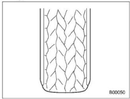
natural_image
Diagram of a container with internal mesh structure, labeled B00050 (no text or symbols on the diagram itself)Roadholdingisgood, andsteeringis responsive. Rollingresistanceislow, so fuelconsumptionisalsolower.
- Abnormallylowtirepressure(tread wornatshoulders)
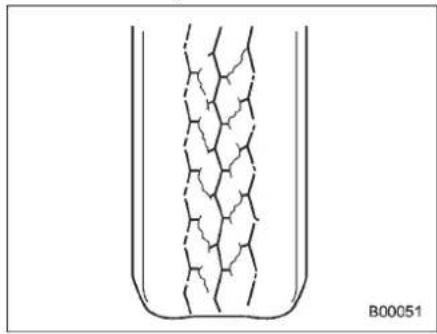
natural_image
Diagram of a U-shaped container with internal mesh structure, labeled B00051 (no text or symbols on the diagram itself)Rollingresistanceishigh,sofuelconsumptionisalsohigher.
- Abnormallyhightirepressure(tread wornincenter)
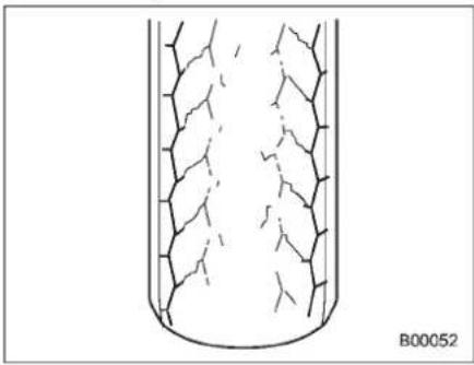
natural_image
Cross-sectional diagram of a cylindrical container with internal crack patterns (no text or symbols)Ridecomfortispoor. Also, the tire magnifiestheeffectsofroad-surface bumpsanddips, possiblyresulting in vehicle damage.

WARNING
Drivingathighspeedswithexcessivelylowtirepressurescancause thetirestodeformseverelyandto rapidlybecomehot.Asharpin-creaseintemperaturecouldcause treadseparation,anddestructionof thetires. Theresultinglossof vehiclecontrolcouldleadtoan accident.
-CONTINUED-
Wheelbalance
Eachwheelwascorrectlybalancedwhen yourvehiclewasnew,butthewheelswill becomeunbalancedasthetiresbecome wornduringuse.Wheelimbalancecauses thesteeringwheeltovibrateslightlyat certainvehiclespeedsanddetractsfrom thevehicle'sstraight-linestability.Itcan alsocausesteeringandsuspensionsystemproblemsandabnormaltirewear.If yoususpectthatthewheelsarenot correctlybalanced,havethemchecked andadjustedbyyourSUBARUdealer. Alsohavethemadjustedaftertirerepairs andaftertirerotation.
NOTE
Lossofcorrectwheelalignment* causesthetirestorewearononeside andreducesthevehicle'srunning stability.ContactyourSUBARUdealer ifyounoticeabnormaltirewear.
*: Thesuspensionsystemisdesignedtohold eachwheelatacertainalignment(relativeto theotherwheelsandtotheroad)foroptimum straight-linestabilityandcorneringperformance.
■Wearindicators
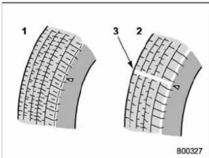
1) Newtread
2) Worntread
3) Treadwearindicator
Each tire incorporates atreadwear indicator, which becomes visible when the depth of the thread grooves decreases to 0.071 in (1.8 mm). A tire must be replaced when the thread wear indicator appears as a solid band across the thread.

WARNING
Whenatire'streadwearindicator becomes visible, the tire is worn beyondtheacceptablelimitand mustbereplacedimmediately.With atireinthiscondition,drivingat high speedsinwetweather can
cause the vehicle to hydroplane. Theresultinglossofvehiclecontrol canleadtoanaccident.
NOTE
Forsafety, inspect the tiretread regularly and replacethetires before their treadwear indicators become visible.
■Tirerotationdirectionmark
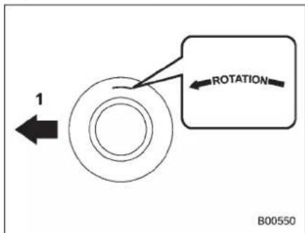
Exampleoftirerotationdirectionmark
1) Front
If the tire has a therotation direction specification, the tire rotation direction marks placed on it's sidewall. When you install atire that ast her tire rotation direction mark, install the tire with
thedirectionmarkfacingforward.
Tirerotation
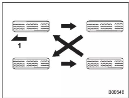
flowchart
graph TD
    A["Input Block 1"] --> B{X}
    C["Input Block 2"] --> B
    B --> D["Output Block"]
    style A fill:#f9f,stroke:#333
    style C fill:#f9f,stroke:#333
    style D fill:#ccf,stroke:#333
Vehiclesequippedwith4non-unidirectionaltires
1) Front
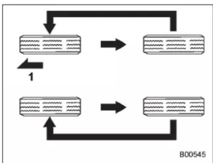
flowchart
graph TD
    A["Process Step 1"] --> B["Process Step 2"]
    B --> C["Output Step"]
    C --> D["Final Output"]
    style A fill:#f9f,stroke:#333
    style B fill:#bbf,stroke:#333
    style C fill:#dfd,stroke:#333
    style D fill:#dfd,stroke:#333
Vehiclesequippedwithunidirectionaltires 1) Front
Tirewearvariesfromwheeltowheel.To maximizethelifeofeachtireandensure thatthetireswearuniformly,itisbestto rotatethetiresevery7,500miles(12,000 km).Movethetirestothepositionsshown intheillustrationeachtimetheyare rotated.
Replaceanydamagedorunevenlyworn tireatthetimeofrotation. After tire rotation, adjust the tire pressures and makesure the wheel nuts are correctly tightened.
Afterdrivingapproximately600miles (1,000km), checkthewheelnutsagain andretightenanynutthathasbecome loose.
Tirereplacement
The wheels and tires are important and integral part of your vehicle's design; they cannot be changed arbitrarily. The tires fitted as standard dequipment are optimally matched to the characteristics of the vehicle and were selected to give the best possible combination of running performance, ride comfort, and service life. It is essential for every tire to have a size and construction matching those shown on the tire placard and to have a speed symbol and load index matching those shown on the tire placard.
Usingtiresofanon-specifiedsizedetracts fromcontrollability,ridecomfort,braking performance,speedometeraccuracy and odometeraccuracy.Italsoreatesincorrectbody-to-tire clearancesand inappropriatelychangesthevehicle'sground clearance.
All four tires must be the same interms of manufacturer, brand (tread pattern), construction, and size. You are advised to replace the tires with new ones that are identical to those fitted as standard equipment.
Forsafevehicleoperation, SUBARU recommendsreplacingallfourtiresat thesametime.
-CONTINUED-
11-30 Maintenance and service

WARNING
- Allfourtiresmustbethesamein termsofmanufacturer,brand (treadpattern),construction,degreeofwear,speedsymbol,load indexandsize.Mixingtiresof differenttypes,sizesordegrees ofwearcanresultindamageto thevehicle'spowertrain.Useof differenttypesorsizesoftires canalsodangerouslyreduce controllabilityandbrakingperformanceandcanleadtoan accident.
- Useonlyradialtires.Donotuse radialtirestogetherwithbelted biastiresand/orbias-plytires. Doingsocandangerouslyreducecontrollability,resulting in anaccident.
■ Wheelreplacement
Whenreplacingwheelsdue,forexample, todamage,makesurethereplacement wheelsmatchthespecificationsofthe wheelsthatarefittedasstandardequipment.Replacementwheelsareavailable fromSUBARUdealers.

WARNING
Useonlythosewheelsthatare specifiedforyourvehicle.Wheels notmeetingspecificationscould interferewithbrakecaliperoperationandmaycausethetirestorub againstthewheelwellhousingduringturns.Theresultinglossof vehiclecontrolcouldleadtoan accident.
Aluminumwheels
●Aluminumwheelscanbescratched anddamagedeasily.Handlethemcarefullytomaintaintheirappearance,performance,andsafety.
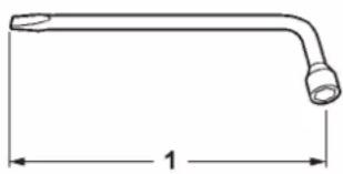
natural_image
Simple line drawing of a bent pipe or tube with a dimension label (no text or symbols)900292
1) Thelengthofthewheelnutwrench

CAUTION
Thereare2 types of wheelnut wrench that apply to different lengths.
Foranaluminumwheelvehicle, the 11.2-inch (285 mm) wheel nut wrenchisequipped as a maintenancetool. And forachromeplated wheel vehicle, the 13.2-inch (335 mm) wheel nut wrenchisequipped
aswell.Alwaysuseawheelnut wrenchforanaluminumwheel.If youuseawrenchforachrome platedwheel,youcannottightenit tothespecifiedtorque.
- Whenanyofthewheelsareremoved andreplacedfortirerotationortochange aflattire,alwayscheckthetightnessof thewheelnutsafterdrivingapproximately 600miles(1,000km).Ifanynutisloose, tightenittothefollowingspecifiedtorque. Atighteningsequencespecificationforthe wheelnutscanbefoundin"Flattires"9-6.
Wheelnutstighteningtorqueforaluminumwheel:
74to89lbf·ft(100to120N·m,10to12kgf·m)
Thistorqueisequivalenttoapplying approximately88to110lbs(40to50kg) atthetopofthewheelnutwrench.
- Neverapplyoiltothethreadedparts, wheelnuts, ortaperedsurfaceofthe wheel.
- Neverletthewheelrubagainstsharp protrusionsorcurbs.
- Whenwheelnuts, balanceweights, or thecentercapisreplaced, besureto replacethemwithgenuineSUBARUparts designedforaluminumwheels.
Chromeplatedwheels(if equipped)
natural_image
Simple line drawing of a bent pipe or handle with a dimension label (no text or symbols)900292
1) Thelengthofthewheelnutwrench

CAUTION
Thereare2typesofwheelnut wrenchesthatapplytodifferent lengths.
Foranaluminumwheelvehicle,the 11.2-inch(285 mm)wheel nut wrenchisequippedasamaintenancetool.Andforachromeplated wheelvehicle,the13.2-inch(335 mm)wheelnutwrenchisequipped aswell.Alwaysuseawheelnut wrenchforachromeplatedwheel.If youuseawrenchforanaluminum
wheel,youcannottightenittothe specifiedtorque.
- Whenanyofthewheelsareremoved andreplacedfortirerotationortochange aflattire,alwayscheckthetightnessof thewheelnutsafterdrivingapproximately 600miles(1,000km).Ifanynutisloose, tightenittothefollowingspecifiedtorque. Atighteningsequencespecificationforthe wheelnutscanbefoundin"Flattires"-9-6.
Wheelnutstighteningtorquefor chromeplatedwheel: 89to111lbf·ft(120to150N·m,12to15 kgf·m)
Thistorqueisequivalenttoapplying approximately86to108lbs(39to49kg) atthetopofthewheelnutwrench.
- Neverapplyoiltothethreadedparts, wheelnuts,ortaperedsurfaceofthe wheel.
- Neverletthewheelrubagainstsharp protrusionsorcurbs.
- When wheelnuts, balance weights, or the center cap is replaced, besureto replacethem with genuine SUBARU parts designed for chrome plated wheels.
11-32 Maintenance and service
Windshieldwasherfluid

CAUTION
Neveruseenginecoolantaswasher fluidbecauseitcouldcausepaint damage.
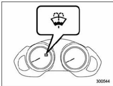
Ifyouspraywasherfluidonthewindshield butthewindshieldwasherfluidwarning lightilluminatesorthesupplyofwasher fluidappearstodiminish,addwasherfluid inthetank.
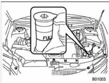
natural_image
Technical line drawing of a car engine bay with internal components and a highlighted component (no text or symbols)Removethewashertankfillercap, then add washer fluid until it reaches the "FULL" markonthetank.
Afteraddingwasherfluid, makesure the windshieldwasherfluid warning light has turned off.
Usewindshieldwasherfluid.Ifwindshield washerfluidisunavailableuseclean water.
Inareaswherewaterfreezesinwinter, useananti-freezetypewindshieldwasher fluid. SUBARUWindshieldWasherFluid contains 58.5% methylalcohol and 41.5% surfactant, by volume. Its freezing temperature varies according to how much it is diluted, as indicated in the following table.
| WasherFluid Concentration | Freezing Temperature |
| 30% | 10.4°F (-12°C) |
| 50% | -4°F (-20°C) |
| 100% | -49°F (-45°C) |

CAUTION
Neveruseenginecoolantaswasher fluidbecauseitcouldcausepaint damage.
Inordertopreventfreezingofwasher fluid,checkthefreezingtemperaturesin thetableabovewhenadjustingthefluid concentrationtotheoutsidetemperature. Ifyoufillthereservoirtankwithafluidwith adifferentconcentrationfromtheone usedpreviously,purgetheoldfluidfrom thepipingbetweenthereservoirtankand washernozzlesbyoperatingthewasher foracertainperiodoftime. Otherwise,if theconcentrationofthefluidremaininging in thepipingistoolowfortheoutside temperature,itmayfreezeandblockthe nozzles.

CAUTION
- Adjustthewasherfluidconcentrationappropriatelyfortheout-
sidetemperature.Iftheconcentrationisinappropriate,sprayed washerfluidmayfreezeonthe windshieldandobstructyour view,andthefluidmayfreezein thereservoirtank.
- State or local regulations on volatile organic compounds may restrict the use of methanol, a common windshield washer anti-freeze additive. Washer fluids containing non-methanol anti-freeze agents should be used only if they provide cold weather protection without damaging your vehicle's paint, wiper blades or washersystem.
Replacementofwiperblades
Grease, wax, insects, orothermaterials onthewindshieldorthewiperblade resultsinjerkywiperoperationandstreakingontheglass. If you cannot remove the streaks after operating the windshield washerorifthewiperoperation is jerky, clean the outersurface of the windshield (or rear window) and the wiper blades using as spongeor soft cloth with an eutral detergentormild-abrasive cleaner. After cleaning, rinse the windshield and wiper blades with clean water. The windshield is clean if beads donot form when your inse the windshield with water.

CAUTION
- Donotcleanthewiperblades with gasoline or asolvent, such as paint thinner or benzine. This will cause deterioration of the wiperblades.
-
When you wish to raise the passenger-sidewiperarm, first raisethedriver-sidewiperarm. Otherwise, the passenger-side wiperassembly and driver-side wiperassembly will toucheach other, possibly resulting in scratches.
-
Whileremovingthewiperblades fromthewiperarms, donot returnthewiperarmstothe originalpositions. Otherwise, thewindshieldsurfacemaybe scratched.
- Whenreturningtheraisedwiperarmstotheoriginalpositions, carefullyreturnthewiperarms onthewindshieldwhilesupportingthemwithyourhands.You shouldnotreturnthewiperarms tothewindshieldonlybythereturnspring.Otherwise,thewiperarmsmaybeformedand/orthewindshieldsurfacemaybescratched.
- Return the passenger-sidewiper armtoits original position before returning the driver-sidewiper armtoits original position. Otherwise, the passenger-side wiper assembly and driver-side wiper assembly will touch each other, possibly resulting in scratches.
If you cannot eliminate the breakthrough even after following this method, replace the wiper blades using the following procedures. Besuretousegenuine SUBARU wiperbladerubbersas replacements.
-CONTINUED-
11-34 Maintenance and service
■Windshieldwiperbladeas-sembly
- Raisethewindshieldwiperarmonthe driver'sside.
- Next, raisethewindshieldwiperarm onthepassenger'sside.
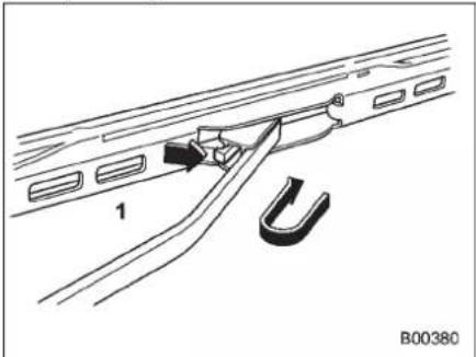
natural_image
Technical line drawing of a mechanical component with labeled parts (no text or symbols beyond labels)1) Stopper
- Removethewiperbladeassembly by holdingitspivotareaandpushingitinthe directionshownbythearrowwhilede-pressingthewiperbladestopper.
- Installthewiperbladeassemblytothe wiperarm.Makesurethatitlocksinplace.
- Lowerthewindshieldwiperarmonthe passenger's sideslowlywhilesupporting itwithyourhands.
- Next, lowerthewindshieldwiperarm onthedriver'ssideslowlywhilesupport-
ingitwithyourhands.
■Windshieldwiperbladerubber
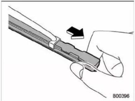
natural_image
Illustration of a hand holding a pen or tool with a black arrow indicating motion (no text or symbols)1) Metalsupport
- Graspthelockedendoftheblade rubberassemblyandpullitfirmlyuntilthe stoppersontherubberarefreeofthe metalsupport.
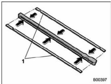
natural_image
Diagram of a mechanical or electrical component with directional arrows and a numbered reference point (B00397), no readable text or symbols present.1)Metalspines
- If thenewbladerubber is not provided with twometal spines, removethemetal spines from the old blade rubber and install them in thenewblader rubber.

CAUTION
Besuretoinstalleachmetalspine soastofititsgroovecompletelyon thecenterridgeofthebladerubber. Doingotherwisemayresultindis- locationandbreakageofthespine duringwiperoperation.
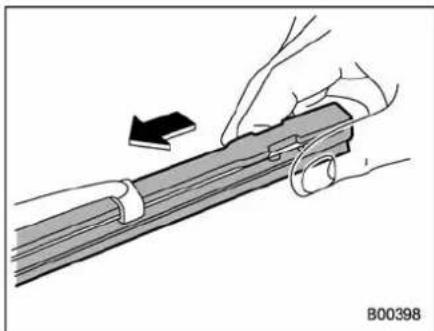
natural_image
Illustration of a hand holding a rifle with an arrow indicating motion (no text or symbols)- Align the claw so the metals support with the grooves in therubber and slide the blader rubber assembly into themetal support until it locks.
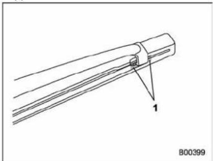
natural_image
Technical line drawing of a mechanical component with labeled part '1' and identifier B00399 (no text or symbols beyond label)1) Stopper
- Besuretopositiontheclawsatthe
endofthemetalsupportbetweenthe stoppersontherubberasshown.Ifthe rubberisnotretainedproperly,thewiper blademayscratchthewindshield.
■ Rearwindowwiperblade assembly
- Raisethewiperarmofftherear window.
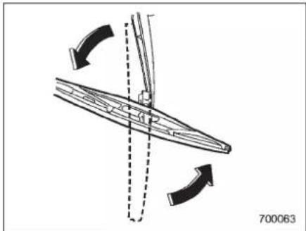
natural_image
Diagram of a ship's hull with directional arrows indicating movement, no text or symbols present- Turnthewiperbladeassemblycounterclockwise.
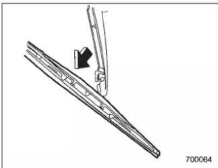
natural_image
Technical line drawing of a mechanical component with an arrow indicating direction (no text or symbols)- Pullthewiperbladeassemblytoward youtoremoveitfromthewiperarm.
■Rearwindowwiperblade rubber
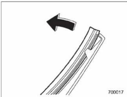
natural_image
Diagram showing a curved arrow pointing to a textured rectangular object, with no visible text or symbols.-CONTINUED-
11-36 Maintenance and service
- Pullouttheendofthebladerubber assemblytounlockitfromtheplastic support.
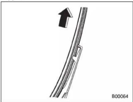
natural_image
Diagram showing a curved pipe or duct with an arrow pointing upward, labeled B00064 (no text or symbols on the diagram itself)- Pullthebladerubberassemblyoutof theplasticsupport.
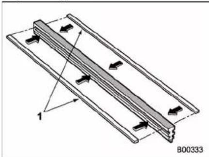
natural_image
Technical diagram of a structural frame with directional arrows and labeled point B00333 (no text or symbols beyond label)1)Metalspines
- If thenewbladerubber is not provided with twometal spines, removethemetal spines from the old blader rubber and install them in thenewblader rubber.
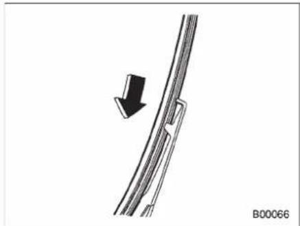
natural_image
Diagram showing a curved pipe or cable with a black arrow indicating direction, labeled B00066 (no text or symbols on the diagram itself)- Align the claw so the plastics support with the grooves in the bladder rubber assembly, then slid the bladder rubber assembly in to place.
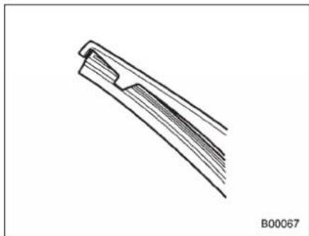
natural_image
Line drawing of a mechanical component or tool with no visible text or symbolsSecurelyretainbothendsoftherubber withthestoppersontheplasticsupport ends. Iftherubberisnotretainedproperly, thewipermayscratchtherearwindow glass.
-
Install the wiper blade assembly to the wiper arm. Makes sure that it locks in place.
-
Hold the wiperarm by hand and slowly lower it in position.
Battery

WARNING
- Beforebeginningworkonornear anybattery,besuretoextinguish allcigarettes,matches,andlighters.Neverexposeabatterytoan openflameorelectricsparks. Batteriesgiveoffagaswhichis highlyflammableandexplosive.
●Forsafety, incaseanexplosion does occur, we are protection or shield you are yes when working near any battery. Never clean overabattery. - Donotletbatteryfluidcontact eyes,skin,fabrics,orpaintbe-causebatteryfluidisacorrosive acid.lfbatteryfluidgetsonyour skinorinyoureyes,immediately flushtheareawithwaterthoroughly.Seekmedicalhelpimmediatelyifacidhasenteredthe eyes.
If batteryfluidisaccidentally swallowed,immediatelydrinka largeamountofmilkorwater, andseekmedicalattentionimmediately.
•Tolessentheriskofsparks,
removerings,metalwatchbands, andothermetaljewelry.Never allowmetaltoolstocontactthe positivebatteryterminal and anythingconnectedtoitWHILEyou areatthesametimeincontact withanyothermetallicportionof thevehiclebecauseashortcircuitwillresult.
- Keep everyone including children awayfromthebattery.
- Chargethebatteryinawell-ventilatedarea.
●Batteryposts,terminals,andrelatedaccessoriescontainlead andleadcompounds,chemicals known to the State of California to cause cancer and reproductive harm. Batteries also contain other chemicals known to the State of Californiatocause cancer. Wash hands after handling.

CAUTION
Neverusemorethan10amperes whenchargingthebatterybecause itwillshortenbatterylife.
Itisunnecessarytoperiodicallycheckthe batteryfluidlevelorperiodicallyrefillwith
distilledwater.
Fuses

CAUTION
Neverreplaceafusewithonehavingahigherratingorwithmaterial otherthanafusebecauseserious damageorafirecouldresult.
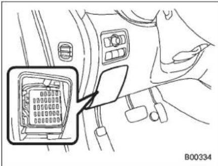
natural_image
Diagram of a car interior showing a connector with a magnified view (no text or symbols)Thefusesaredesignedtomeltduringan overloadtopreventdamagetothewiring harnessandelectricalequipment. The fusesarelocatedintwofuseboxes. One islocatedundertheinstrumentpanel behindthefuseboxcoveronthedriver's seatside.
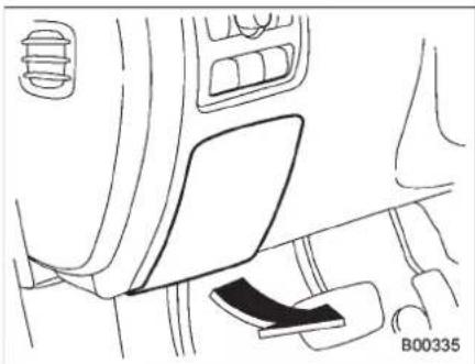
natural_image
Interior view of a car showing the dashboard, seatbelt, and dashboard panel (no text or symbols)Openthelidthatislocatedabovethe hoodreleaseknobandpullittowardyou toremoveit.
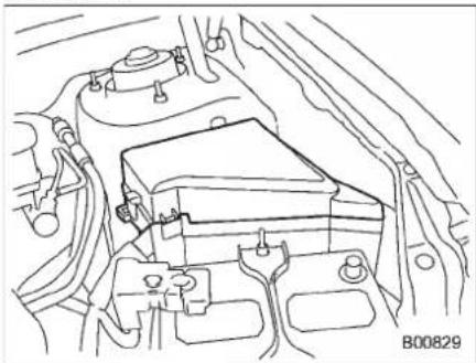
natural_image
Technical line drawing of an engine compartment with no visible text or symbolsTheotheroneishousedintheengine compartment.
natural_image
Technical line drawing of a mechanical component with no visible text or symbolsThesparefusesarestoredinthemain fuseboxcoverintheenginecompartment.
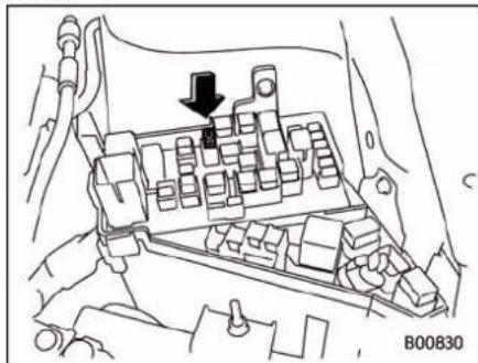
Thefusepullerisstoredinthemainfuse boxintheenginecompartment.
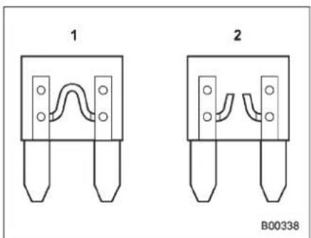
1) Good
2)Blown
Ifanylights, accessoriesorotherelectrical controlsdonotoperate, inspect the corresponding fuse. Ifafusehasblown, replace it.
- Turntheignitionswitchtothe"LOCK" positionandturnoffallelectricalaccessories.
- Removethecover.
- Determinewhichfusemaybeblown. Lookatthebacksideofeachfusebox coverandreferto"Fusesandcircuits" 12-5.
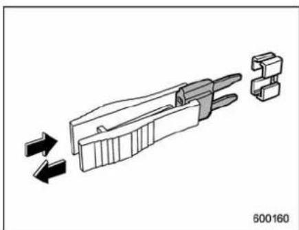
natural_image
Diagram of a connector assembly showing internal structure and directional arrows (no text or symbols)4.Pulloutthefusewiththefusepuller.
5. Inspect the fuse. If has blown, replace it with aspare fuse of the same rating.
6. If the same fuse blows again, this indicates that it's system has a problem. Contact your SUBARU dealer for repairs.
Mainfuse
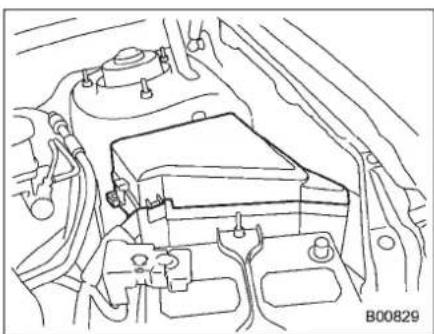
natural_image
Technical line drawing of an engine compartment with no visible text or symbolsMainfusebox
Themainfusesaredesignedtomelt duringanoverloadtopreventdamageto thewiringharnessandelectricalequipment. Check themainfusesifany electricalcomponentfailstooperate(exceptthestartermotor)andotherfusesare good. Ameltedmainfusemustbe replaced. Useonlyreplacementswiththe samespecifiedratingasthemeltedmain fuse. Ifamainfuseblowsafteritis replaced, havetheelectricalsystem checkedbyyournearestSUBARUdealer.
11-40 Maintenance and service
Installationofaccessories
AlwaysconsultyourSUBARUdealer beforeinstallingfoglightsoranyother electricalequipmentinyourvehicle. Such accessoriesmaycausetheelectronic systemtomalfunctioniftheyareincorrectlyinstalledoriftheyarenotsuitedfor thevehicle.
Replacingbulbs

WARNING
Bulbsmaybecomeveryhotwhile illuminated.Beforereplacingbulbs, turnoffthebulbsandwaituntilthe bulbscooldown.Otherwise,thereis ariskofsustainingaburninjury.

CAUTION
Replaceanybulbonlywithanew bulbofthespecifiedwattage.Using abulbofdifferentwattagecould resultinafire.Forthespecified wattageofeachbulb,referto"Bulb chart" 12-8.
■Headlights(modelswithHID headlights)

WARNING
High-intensity-discharge(HID)bulbs are used forthelowbeamsofthe headlights. TheseHIDbulbsusean extremelyhighvoltage.Toavoid the riskofanelectricshockthatcould resultinseriousinjury,observethe
followingprecautions.
- Donotreplace anyheadlight bulbs(bothlowbeamandhigh beam)byyourself.
- Donotremove/restorethehead-lightassembliesbyyourself.
- Donotremoveanyheadlight-assemblycomponentsbyyourself.
For replacement, contact your SUBARUdealer.
■Headlights(modelswithout HIDheadlights)

CAUTION
Halogenheadlightbulbsbecome veryhotwhileinuse.lfyoutouch thebulbsurfacewithbarehandsor greasy gloves, fingerprints or greaseonthebulb surfacewill developintohotspots,causingthe bulbtobreak.Iftherearefinger printsorgreaseonthebulbsurface, wipethemawaywithasoftcloth moistenedwithalcohol.
NOTE
- Ifheadlightaimingisrequired, consultyourSUBARUdealerforproper adjustmentoftheheadlightaim.
•Itmaybedifficulttoreplacethe bulbs.Havethebulbsreplacedbyyour SUBARUdealerifnecessary.
▼Lowbeamlightbulbs(right-hand side)
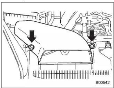
natural_image
Technical diagram of a car engine component with two arrows indicating parts of the handle (no text or symbols present)- Useascrewdrivertoundotheclipson theairintakeduct, thenremovetheair intakeduct.
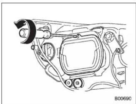
natural_image
Technical line drawing of a car head panel assembly (no text or symbols)- Useascrewdrivertoremovethebulb cover.
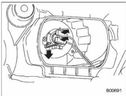
natural_image
Technical line drawing of a mechanical component with internal parts and directional arrows (no text or symbols)- Disconnect the electrical connector.
- Removetheretainerspring.
-
Replacethebulb, thensettheretainer springsecurely.
-
Reconnect the electrical connector.
- Install the bulb cover with the fixing screws.
- Install the air intakeduct with the clips.
NOTE
ContactyourSUBARUdealerforthe bulbreplacementoftheleft-handside.
▼Highbeamlightbulbs
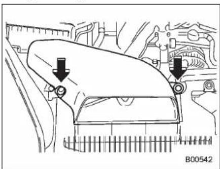
natural_image
Technical diagram of a car engine compartment with two downward arrows indicating parts of the head (no text or symbols present)Right-handside
1. Useascrewdrivertoundotheclipson theairintakeduct, thenremovetheair intakeduct(right-handside).
11-42 Maintenance and service

natural_image
Technical line drawing of a mechanical assembly with no visible text or symbolsLeft-handside
- Useascrewdrivertoremovethe securedclipofthewashertank. Tomake iteasytoaccessthebulb, movethe washertank to the horizontaldirection (left-handside).
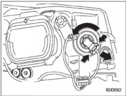
natural_image
Technical line drawing of a mechanical assembly with no visible text or symbols- Disconnect the electrical connector from the bulb.
- Removethebulbfromtheheadlight assemblybyturningitcounterclockwise.
- Replacethebulbwithnewone. At this time, usecarenottotouchthebulb surface.
- Reconnect the electrical connector.
- Toinstallthebulbtotheheadlight assembly, turnitclockwise until it clicks.
- Install the airintakeduct with clips (right-handside).
- Setthewashertanktotheoriginal placeandsecureitbyclip(left-handside).
■ Parkinglight(right-hand side)
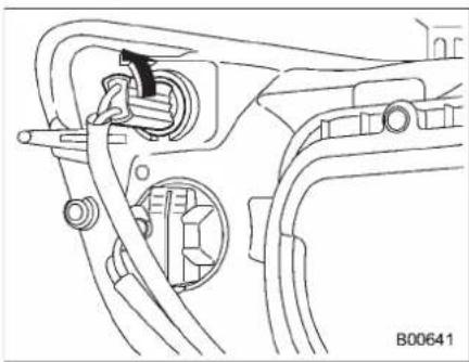
natural_image
Technical line drawing of a mechanical assembly with no visible text or symbols- Removethebulbsocketfromthe
headlightassemblybyturningitcounterclockwise.
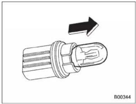
natural_image
Technical illustration of a mechanical component with an arrow indicating direction (no text or symbols)2.Pullthebulboutofthesocket.
3.Installanewbulb.
4. Setthebulbsocketintotheheadlight assemblyandturnitclockwiseuntil locks.
NOTE
Contact your SUBARU dealer for the bulbreplacementoftheleft-handside.
■ Frontturnsignallight(right-handside)
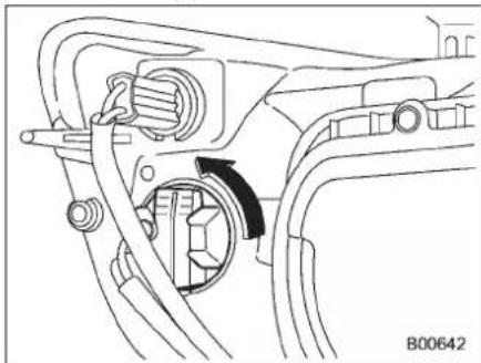
natural_image
Mechanical assembly diagram showing a rotating component with a curved arrow indicating rotation (no text or symbols)- Removethebulbsocketfromthe headlightassemblybyturningitcounterclockwise.
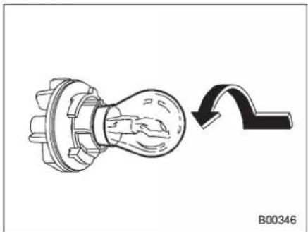
natural_image
Technical line drawing of a mechanical component with a curved arrow indicating motion (no text or symbols)- Removethebulbfromthesocketby pushingitandturningcounterclockwise.
- Installanewbulb.
- Setthebulbsocketintotheheadlight assemblyandturnitclockwiseuntil locks.
NOTE
ContactyourSUBARUdealerforthe bulbreplacementoftheleft-handside.
Frontfoglight
Itmaybedifficulttoreplacethebulbs. HavethebulbsreplacedbyyourSUBARU dealerifnecessary.
■Rearcombinationlights
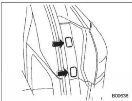
natural_image
Technical line drawing of a mechanical component with two black arrows indicating features (no text or symbols)- Removethetwocoversbyinserting thetipofaflat-headscrewdriver.
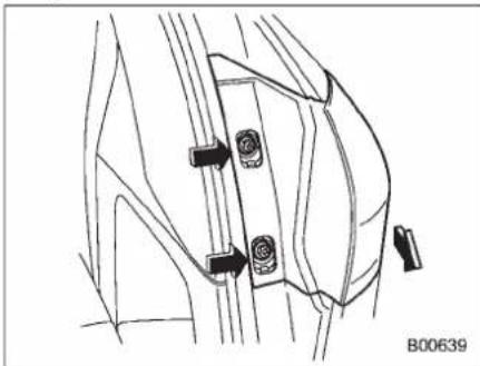
natural_image
Technical line drawing of a mechanical component with two connectors and a base, no text or symbols present- UsingaPhillipsscrewdriver, remove theupperandlowerscrews. Then, slide
-CONTINUED-
11-44 Maintenance and service
therearcombinationlightassemblyrearwardandremoveitfromthevehicle.
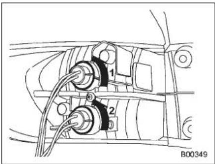
1) Brake/taillight
2)Rearturnsignallight
3. Removethebulbholderfromtherear combinationlightassemblybyturningit counterclockwise.
4. Removethebulbfromthesocketby pushingitandturningcounterclockwise.
5.Installanewbulb.
6. Setthebulbholderintotherear combinationlightassemblyandturnit clockwiseuntilillocks.
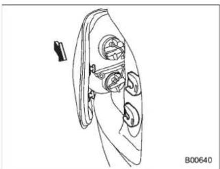
natural_image
Technical line drawing of a mechanical component with no visible text or symbols- Reinstall therear combination light assembly by sliding the two-pronged part of the combination light assembly securely to each holder of the vehicleside.
- Tightenthewomountingscrews, and thenclosethecovers.
■Back-uplight/Taillight
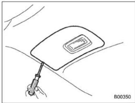
natural_image
Line drawing of a medical or diagnostic device with a clip and handle, no text or symbols present- Useaflat-headscrewdrivertoremove thelightcoverfromthereargatetrim.
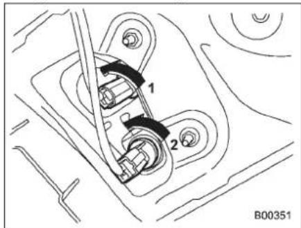
1) Taillight
2)Back-uplight
- Turnthebulbsocketcounterclockwise andremoveit.
- Pullthebulboutofthebulbsocketand replaceitwithanewone.
- Install the bulb socket by turning it clockwise.
- Install the light cover on thereargate.
■Reargatelight
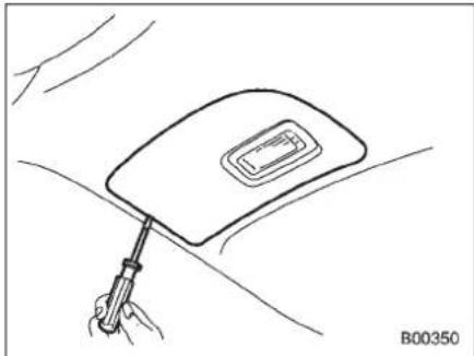
natural_image
Line drawing of a hand holding a tool near a car's side panel (no text or symbols)- Useaflat-headscrewdrivertoremove thereargatelightassemblyfromtherear gatetrim.
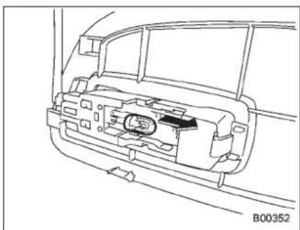
natural_image
Technical line drawing of a car interior showing internal components and structural lines (no text or symbols)- Pullthebulboutofthebulbsocket and replaceitwithanewone.
- Install thereargatelightassembly on thereargate.
Licenseplatelight
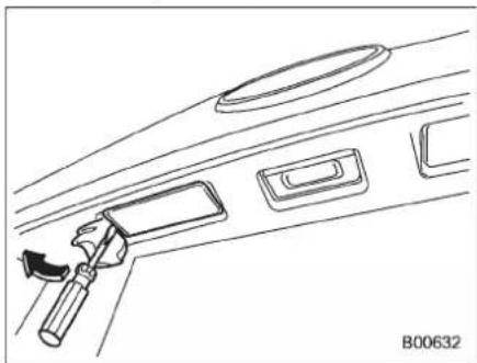
natural_image
Line drawing of a car interior panel with handle and compartments (no text or symbols)- Wrapaflat-headscrewdriverinvinyl tapeorcloth, insertitintothegapbetween the licenseplatelightassembly and the reargate.
- Carefullyprythelightassemblyto removeit.
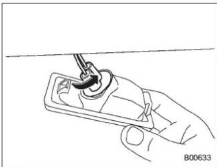
natural_image
Line drawing of a hand holding a small electronic device with a tool inserted (no text or symbols visible)- Removethebulbsocketfromthe licenseplatelightassemblybyturningit counterclockwise.
-CONTINUED-
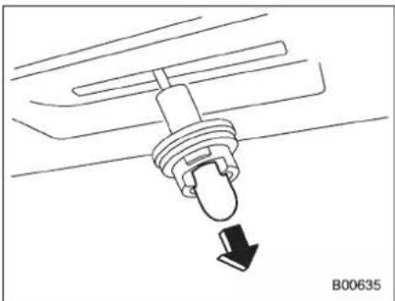
natural_image
Diagram of a mechanical component with a downward arrow indicating direction (no text or symbols)- Pullthebulboutofthesocket.Installa newbulb.
- Setthebulbsocketintothelicense platelightassemblyandturnitclockwise untilitlocks.
- Reinstallthelicenseplatelightassemblytothereargate.
Domelight
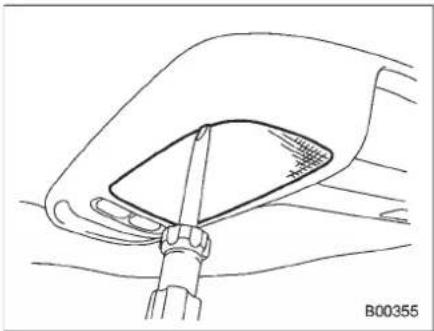
natural_image
Technical line drawing of a car seatbelt mechanism (no text or symbols)ModelswithRearSeatEntertainment
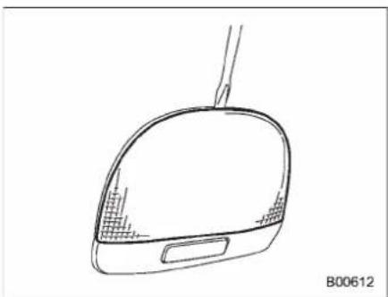
natural_image
Line drawing of a computer mouse head (no text or symbols)ModelswithoutRearSeatEntertainment
- Removethelensbypryingtheedgeof thelenswithaflat-headscrewdriver.
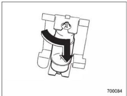
natural_image
Illustration of a person standing in a chair with arms extended, no text or symbols present- Turnthebulbuntiltheflatsurfacesat itsendsarealignedvertically. Pullthebulb straightdownwardtoremoveit.
3.Installanewbulb.
4.Reinstallthelens.
Maplight
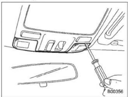
natural_image
Line drawing of a car interior showing a tool inserted into the dashboard area, with no visible text or symbols.- Removethelensbypryingtheedgeof thelenswithaflat-headscrewdriver.
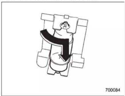
natural_image
Simple line drawing of a person holding an object, no text or symbols present- Turnthebulbuntiltheflatsurfacesat itsendsarealignedvertically. Pullthebulb
straightdownwardtoremoveit.
3. Installanewbulb.
4.Reinstallthelens.
■Vanitymirrorlight
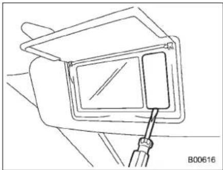
natural_image
Line drawing of a mechanical component with a tool inserted, no visible text or symbols- Removethelensbypryingtheedgeof thelenswithaflat-headscrewdriver.
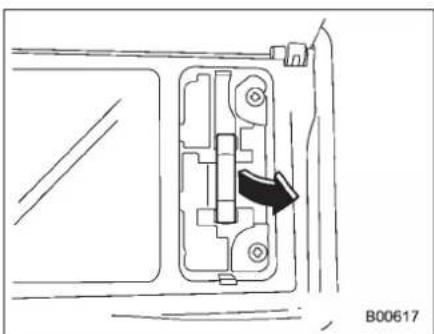
natural_image
Technical diagram of a mechanical component with an arrow indicating direction (no text or symbols present)2.Pullthebulboutofthesocket.
3. Installanewbulb.
4.Reinstallthelens.
■Doorsteplight
Itmaybedifficulttoreplacethebulbs.
HavethebulbsreplacedbyyourSUBARU dealerifnecessary.
Cargoarealight
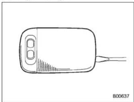
natural_image
Line drawing of a handheld device with a sensor and connector (no text or symbols)-
Removethecargoarealightassembly bypryingtheedgeofthelightwithaflat-headscrewdriver.
-
Removethelensfromthecargoarea lightassembly.
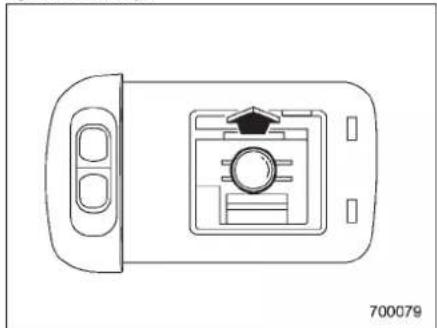
natural_image
Top-down schematic of a device with a central control panel and two side buttons (no text or symbols)3.Pullthebulboutofthesocket.
4. Installanewbulb.
5. Reinstallthelenstothecargoarea lightassembly.
6. Reinstall the cargo are alight assembly to the or of trim.
Specifications
Specifications....12-2
Dimensions....12-2
Engine....12-2
Electricalsystem....12-3
Capacities....12-3
Tires....12-3
Wheelalignment....12-4
Fusesandcircuits....12-5
Fusepanellocatedinthepassenger compartment....12-5
Fusepanellocatedintheengine compartment....12-7
Bulbchart....12-8
Vehicleidentification....12-11
12-2 Specifications
Specifications
Thesespecificationsaresubjecttochangewithoutnotice.
■Dimensions
in(mm)
| Overalllength191.5(4,865) | ||
| Overallwidth73.9(1,878) | ||
| Overallheight | Withoutroofrail66.7(1,695) | |
| Withroofrail68.1(1,730) | ||
| Wheelbase108.1(2,745) | ||
| Tread | Front62.0(1,575) | |
| Rear62.0(1,575) | ||
| Groundclearance | 8.3(211) | |
Engine
| Enginemodel | EZ36D(3.6L,DOHC,non-turbo) |
| EnginetypeHorizontallyopposed,liquidcooled6cylinder,4strokegasolineengine | |
| Displacementcc(cu-in)3,630(222) | |
| Bore × Stroke in (mm) | 3.62 × 3.58 (92.0 × 91.0) |
| Compressionratio | 10.5:1 |
| Firingorder | 1 - 6 - 3 - 2 - 5 - 4 |
Electricalsystem
| Batterytypeandcapacity(5HR)75D23L(12V-52AH) | |
| Alternator12V-130A | |
| Sparkplugs | SILFR6C11(NGK) |
■ Capacities
| Fueltank16.9USgal(64liters,14.1Impgal) | |
| Engineoil | 6.7USqt(6.3liters,5.5Impqt) |
| Transmissionfluid | 10.4USqt(9.8liters,8.6Impqt) |
| Frontdifferentialgearoil1.5USqt(1.4liters,1.2Impqt) | |
| Reardifferentialgearoil0.8USqt(0.8liter,0.7Impqt) | |
| Powersteeringfluid0.9USqt(0.9liter,0.8Impqt) | |
| Enginecoolant | 8.0USqt(7.6liters,6.7Impqt) |
Each quantity indicated above is only a guideline. The necessary quantity for replacement may differ slightly depending on the temperature and other factors.
Tires
| Tiresize | P255/55R18104H | |
| Wheelsize18 × 8JJ | ||
| PressureFront | 33psi(230kPa,2.3kgf/cm ^2 ) | |
| Rear32psi(220kPa,2.2kgf/cm | ^2 ) | |
| Temporarysparetire | Size | T165/80R17 |
| Pressure | 60psi(420kPa,4.2kgf/cm ^2 ) | |
12-4 Specifications
Wheelalignment
| ToeFront0in(0mm) | ||
| Rear0.0787in(2mm) | ||
| CamberFront0°00' | ||
| Rear-0°31' |
Fusesandcircuits
■Fusepanellocatedinthepassengercompartment
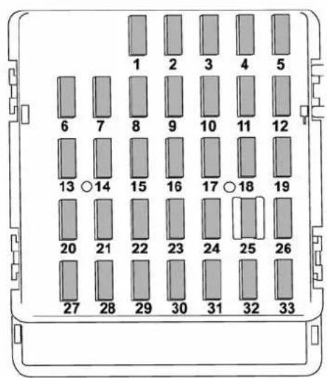
C00123
| Fuse panel | Fuse rating | Circuit |
| 120A | ●Trailerhitchconnector | |
| 2 | Empty | |
| 315A | ●Doorlocking | |
| 47.5A | ●Frontwiperdeicerrelay●Moonroof | |
| 57.5A | ●Combinationmeter | |
| 67.5A | ●Remotecontrolrear viewmirrors●Seatheaterrelay | |
| 715A | ●Combinationmeter●Integratedunit | |
| 815A | ●Stoplight | |
| 920A | ●Mirrorheater●Frontwiperdeicer | |
| 107.5A | ●Powersupply(battery) | |
| 117.5A | ●Tumsignalunit | |
| 1215A | ●Automatictransmission unit●SRSairbagsystem (sub)●Enginecontrolunit●Integratedunit |
-CONTINUED-
12-6 Specifications
| Fuse panel | Fuse rating | Circuit |
| 1320A | ●Cargosocket | |
| 1415A | ●Positionlight●Taillight●Rearcombinationlight | |
| 15 | Empty | |
| 1610A | ●Illumination | |
| 1715A | ●Seatheaters | |
| 1810A | ●Back-uplight | |
| 197.5A | ●Headlightrightsidere-lay | |
| 20Empty | ||
| 217.5A | ●Starterrelay | |
| 2215A | ●Airconditioner●Rearwindowdefogger relaycoil | |
| 2315A | ●Rearwiper●Rearwindowwasher | |
| 2415A | ●Audiounit | |
| 2515A | ●SRSairbagsystem (main) | |
| 267.5A | ●Powerwindowrelay | |
| 2715A | ●Rearblowerfan |
| Fuse panel | Fuse rating | Circuit |
| 2815A | ●Rearblowerfan | |
| 2915A | ●Foglight | |
| 3030A | ●Frontwiper | |
| 317.5A | ●Autoairconditionerunit●Integratedunit | |
| 327.5A | ●Headlightleftsiderelay | |
| 337.5A | ●VehicleDynamicsControlunit |
Fusepanellocatedintheenginecompartment
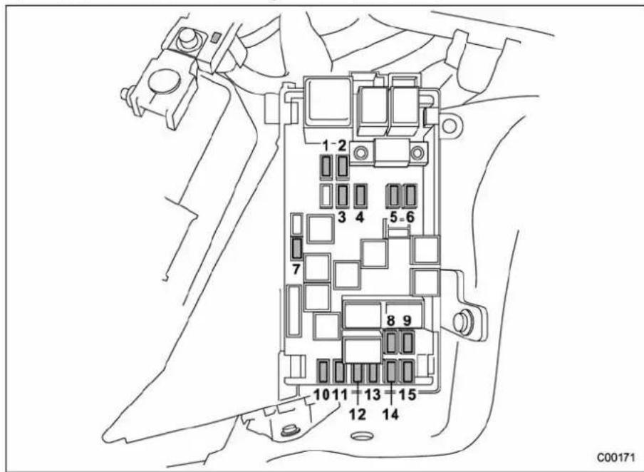
| Fuse panel | Fuse rating | Circuit |
| 130A | ●VehicleDynamicsControlunit | |
| 225A | ●Mainfan(coolingfan) | |
| 325A | ●Mainfan(coolingfan) | |
| 420A | ●Consolesocket | |
| 515A | ●Headlight(rightside) | |
| 615A | ●Headlight(leftside) | |
| 720A | ●Backup | |
| 815A | ●Horn | |
| 925A | ●Rearwindowdefogger | |
| 1015A | ●Fuelpump | |
| 1115A | ●Automatictransmission controlunit | |
| 127.5A | ●Enginecontrolunit | |
| 1315A | ●Turnandhazardwarning flasher | |
| 1420A | ●Parkingswitch | |
| 157.5A | ●Alternator |
12-8 Specifications
Bulbchart
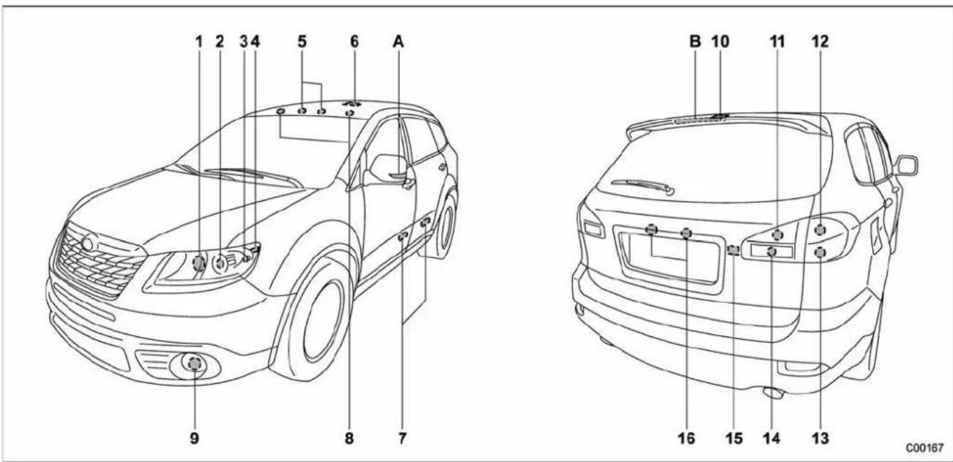
NOTE LightsAandBaretheLED(LightEmittingDiode)type.ConsultyourSUBARUdealerforreplacement.
WattageBulbNo.
1) Highbeamheadlight 12V-65WHB3
2) Lowbeamheadlight
ModelswithHIDlight12V-35WD1S
ModelswithoutHIDlight12V-55WH7
3) Frontturnsignal/Parkinglight12V-28/8W2357NA
4) Parking/Frontsidemarkerlight12V-5W168(W5W)
5)Maplight12V-8W-
6) Domelight
ModelswithRearSeatEntertainment12V-5W-
ModelswithoutRearSeatEntertainment12V-8W-
7)Doorsteplight 12V-3W-
8) Vanitymirrorlight 12V-3W
9) Foglight 12V-55W H3
| 10) | Cargo area light | 12V-13W | 912 |
| 11) | Tail light | 12V-5W | 168(W5W) |
| 12) | Brake/tail light | 12V-27/8W | 1157(W27/8W) |
| 13) | Rear turn signal light | 12V-27W | 1156(W27W) |
| 14) | Back-up light | 12V-16W | 921(W16W) |
| 15) | Rear gate light | 12V-5W | (W5W) |
| 16) | License plate light | 12V-5W | 168(W5W) |
| A) | Sideturnsignallight | - | - |
| B) | Highmountstoplight | - | - |

WARNING
- Bulbs may become very hot while illuminated. Before replacing bulbs, turnoff the bulbs and wait until the bulbs cool down. Otherwise, there is a risk of sustaining a burn injury.
- For models with HID low beam headlights, observe the following precautions. Not doing so carries the risk of an electric shock that could result in serious injury because the HID bulbs use an extremely high voltage.
- Do not replace any headlight bulbs (both low beam and high beam) by yourself.
- Do not remove/restore the headlightassembliesbyyourself.
- Do not remove any headlight-assembly components by yourself.
For replacement, contact your SUBARU dealer.
12-10 Specifications

CAUTION
Replaceanybulbonlywithanew bulbofthespecifiedwattage. Using abulbofdifferentwattagecould resultinafire.
Vehicleidentification
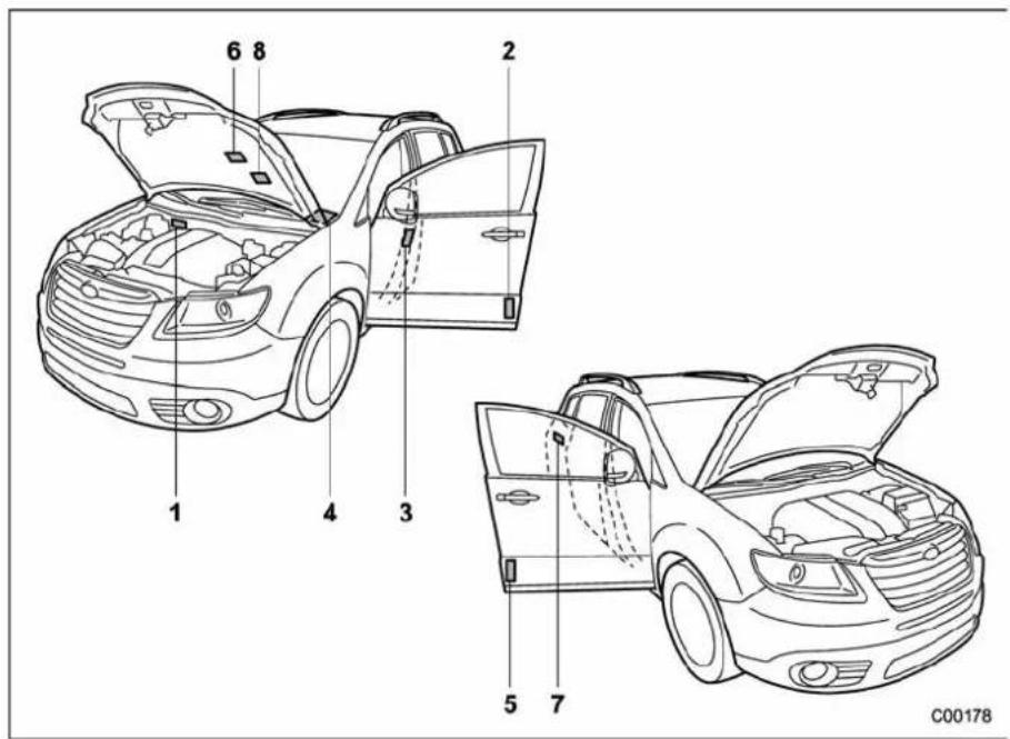
1) Vehicle identification number
2) Certificationandbarcodelabel
3) Tireinflationpressurelabel
4) Vehicleidentificationnumberplate
5) Modelnumberlabel
6)Emissioncontrollabel
7)Fuellabel
8) Airconditionerlabel
| -1.5 | -1.5 | -1.5 | -1.5 |
Consumer information and Reporting safety defects
ForU.S.A....13-2
Tireinformation....13-2
Tirelabeling....13-2
Recommended tire inflation pressure....13-5
Glossaryoftireterminology....13-7
Tirecare-maintenanceandsafety practices....13-11
Vehicleloadlimit-howtodetermine....13-11
Determiningcompatibilityoftireandvehicle loadcapacities....13-14
Adversesafetyconsequencesofoverloading onhandlingandstoppingandontires....13-14
StepsforDeterminingCorrectLoadLimit.....13-15
Uniformtirequalitygradingstandards....13-15 Treadwear....13-16
TractionAA,A,B,C....13-16
TemperatureA,B,C....13-16
Reportingsafetydefects(U.S.A.) 13-17
ForU.S.A.
The following information has been compiled according to Code of Federal Regulations "Title49, Part 575".
Tireinformation
Tirelabeling
Manymarkings(e.g. Tiresize, Tire IdentificationNumberorTIN)are placedonthesidewallofatireby tiremanufacturers. These markings can provide you with useful information on the tire.
▼Tiresize
Yourvehiclecomesequipped with P-Metrictiresize.Itisimportant to understand the tresizingsystemin selecting the propertirefory our vehicle.Hereis abrief review of the tiresizingsystemwithabreakdown of its individualelements.
PMetric
WiththeP-Metricsystem, Section Width is measured in millimeters. Toconvertmillimetersintoinches, divide by 25.4. The Aspect Ratio (SectionHeightdividedbySection Width) helpsprovidemoredimensional information about the tire size.
Example:
| P(1) | 255/ (2) | 55/ (3) | R(4) | 18/ (5) |
(1) P=Certainiretypeusedon lightdutyvehiclessuchaspassengercars
(2) SectionWidthinmillimeters
(3) AspectRatio(=sectionheight ÷ sectionwidth).
(4) R=RadialConstruction
(5) Rimdiameterin inches
▽LoadandSpeedRatingDescriptions
Theloadandspeedratingdescriptionswillappearfollowingthesize designation.
Theyprovidetwoimportantfacts aboutthetire.First,thenumber designationisitsloadindex.Second,theletterdesignationindicates thetire'sspeedrating.
Example:
P 255 / 55 R 18 104 H
Size designation (6) (7)
(6)LoadIndex:Anumericalcode which specifiesthemaximumload atirecancarryatthespeed indicated by its speed symbol, at maximum inflation pressure. Forexample, "104" means 1,984 lbs (900kg), "100" means 1,764 lbs (800kg), "90" means 1,323 lbs (600 kg).

WARNING
Loadindicesapplyonlytothe tire,nottothevehicle.Putting aloadratedtireonanyvehicle doesnotmeanthevehiclecan beloadeduptothetire'srated load.
(7)SpeedRating:An alphabetical system describing atire's capability to travel a latest established and predetermined speeds.
Forexample, "H" means 130 mph
(210km/h).

WARNING
- Speedratingsapplyonlyto thetire, nottothevehicle. Puttingaspeedratedtireon anyvehicledoesnotmean thevehiclecanbeoperated atthetire'sratedspeed.
- Thespeedratingisvoidif thetiresarewornout,damaged, repaired, retreaded, or otherwisealtered from their original condition. If tires are repaired, re-treaded, or otherwisealtered, they may not be suitable for originalequipment tired designed loads and speeds.
▼ TireIdentificationNumber(TIN)
TireIdentificationNumber(TIN)is markedontheintendedoutboard sidewall.TheTINiscomposedof fourgroups.Hereisabriefreview oftheTINwithabreakdownofits
individualelements.
DOT XX XX XXX XXXX
(1) (2) (3) (4)
(1) Manufacturer's Identification Mark
(2)TireSize
(3) TireTypeCode
(4)DateofManufacture
The first two figures identify the week, starting with "01" to represent the first full week of the calendar year; these second two figures represent they year. Forexample, 0101 mean the 1st week of 2001.
▼ Othermarkings
The followingmakings are also placedonthesidewall.
▽Maximumpermissibleinflation pressure
Themaximumcoldinflationpressure to which thistire maybe inflated. For example, "300 kPa (44PSI)MAX.PRESS".
-CONTINUED-
ConsumerinformationandReportingsafetydefects
▽Maximumloadrating
Theloadratingatthemaximum permissibleweightloadforthistire. Forexample, "MAX.LOAD730kg (1609LBS)@300kPa(44PSI) MAX.PRESS."

WARNING
Maximumloadratingapplies onlytothetire,nottothe vehicle.Puttingaloadrated tireonanyvehicledoesnot mean the vehicle can be loadeduptothetire'srated load.
▽Constructiontype
Applicableconstructionofthistire. Forexample, "TUBELESSSTEEL BELTEDRADIAL"
▽Construction
Thegenericnameofeachcord material usedintheplies(both sidewallandtreadarea)ofthistire. Forexample, "PLIES:TREAD2
STEEL + 2 POLYESTER + 1 NYLON SIDEWALL 2 POLYESTER"
▽ Uniform Tire Quality Grading (UTQG)
Fordetails, referto "Uniformtire qualitygradingstandards" 13-15
■Recommendedtireinflationpressure
▼Recommendedcoldtireinflationpressure
Recommendedcoldtireinflationpressureforyourvehicle'stiresisasfollows.
| Tiresize | P255/55R18104H | |
| Wheelsize18 × 8JJ | ||
| PressureFront | 33psi(230kPa,2.3kgf/cm ^2 ) | |
| Rear32psi(220kPa,2.2kgf/cm ^2 ) | ||
| Temporarysparetire | SizeT165/80R17 | |
| Pressure | 60psi(420kPa,4.2kgf/cm ^2 ) | |
▼Vehicleplacard
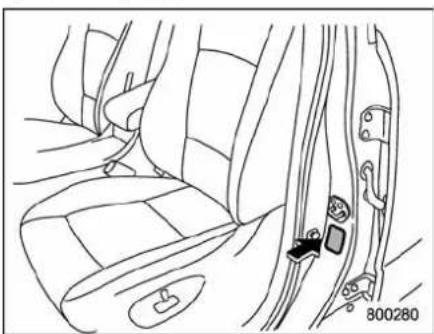
natural_image
Line drawing of a car seatbelt with a black clip inserted, showing no text or symbolsThe vehicle placardisaffixed to the driver's side B-pillar.
Example:
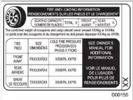
The vehicle placard shows original tiresize, recommended cold tire inflation pressure oneachtire at maximum loaded vehicle weight, seating capacity and loading information.
▼Adversesafetyconsequences ofunder-inflation
Drivingathighspeedswithexcessivelylowtirepressurescancause thetirestoflexseverelyandto rapidlybecomehot.Asharpin-creaseintemperaturecouldcause treadseparation,andfailureofthe tire(s).Possibleresultinglossof vehiclecontrolcouldleadtoan accident.
▼Measuring and adjusting air pressure to achieve proper inflation
Checkand, if necessary, adjust the pressure of each tire (including the spare) at least once a month and before any long journey. Check the tire pressures when the tires are cold. Use a pressure gauge to adjust the tire pressure to
specificvalues. Driving evena shortdistancewarmsupthetires andincreasesthetirepressures. Also, the tirepressures are affected by the outside temperature. It is best to check tire pressure outdoors before driving the vehicle. When atire becomes warm, the air inside it expands, causing the tire pressure to increase. Becareful not to mistakenly release air from a warm tiretoreduce its pressure.
■Glossaryoftireterminology
- Accessoryweight
The combined weight (in excess of those standard items which maybe replaced) of automatic transmission, powersteering, powerbrakes, powerwindows, powerseats, radio, and heater, to the extent that these items are available as factory-installed equipment (whether installed or not).
•Bead
Thepartofthetirethatismadeof steelwires,wrappedorreinforced byplycordsandthatisshapedtofit therim.
- Beadseparation
Abreakdownofthebondbetween componentsinthebead.
•Biasplytire
Apneumaticireinwhichtheply cordsthatextendtothebeadsare laidatalternateanglessubstantially lessthan90degreestothecenter-lineofthetread.
•Carcass
Thetirestructure, excepttreadand
sidewallrubberwhich,whenin- flated,bearstheload.
- Chunking
The pressure in atirethathas been driven less than 1 mileor has been standing forth three hours or more.
•Cord
Thestrandsformingthepliesinthe tire.
•Cordseparation
Thepartingofcordsfromadjacent rubbercompounds.
•Cracking
Anypartingwithinthetread, sidewall, orinnerlinerofthetire extendingtocordmaterial.
•Curbweight
The weight of a motor vehicle with standard equipment including the maximum capacity off fuel, oil and coolant, and if so equipped, air conditioning and additional weight optional engine.
•Extraloadtire
Atiredesignedtooperateathigher loadsandhigherinflationpressure thanthecorrespondingstandard tire.
•Groove
Thespacebetweenwoadjacent treadribs.
•Innerliner
Thelayer(s)formingtheinsidesurfaceofatubelesstirethatcontains theinflatingmediumwithinthetire.
•Innerlinerseparation
Thepartingoftheinnerlinerfrom cordmaterialinthecarcass.
•Intendedoutboardsidewall
(1) Thesidewall that contains a whitewall, bears white lettering or bears manufacturer, brand, and/or model namemolding that is higher or deeper than the samemolding on the others side-wallof the tire, or
(2) Theoutwardfacingsidewall ofanasymmetricaltirethathas aparticularsidethatmustal-waysfaceoutwardwhenmount-
-CONTINUED-
ingonavehicle.
•Lighttruck(LT)tire
Atiredesignatedbyitsmanufacturerasprimarilyintendedforuse onlightweighttruckssormultipurposepassengervehicles.
- Loadrating
Themaximumloadthatatireis ratedtocarryforagiveninflation pressure.
•Maximuminflationpressure
Themaximumcoldinflationpres- suretowhichatiremaybeinflated.
•Maximumloadrating
Theloadratingforatireatthe maximum permissible inflation pressureforthattire.
•Maximumloadedvehicleweight
Thesumof:
(a)Curbweight
(b)Accessoryweight
(c)Vehiclecapacityweight
(d)Productionoptionsweight
•Maximumpermissibleinflation pressure
Themaximumcoldinflationpres- suretowhichatiremaybeinflated.
•Measuringrim
Therimonwhichatireisfittedfor physicaldimensionrequirements.
•Normaloccupantweight
150lbs(68kg)timesthenumberof occupantsspecifiedinthesecond columnofTable1thatisappended totheendofthissection.
•Occupantdistribution
Distributionofoccupantsinavehicleasspecifiedinthethirdcolumn ofTable1 thatisappendedtothe endofthissection.
- Opensplice
Anypartingatanyjunctionoftread, sidewall,orinnerlinerthatextends tocordmaterial.
-Outerdiameter
Theoveralldiameterofaninflated newtire.
•Overallwidth
Thelinear distancebetween the exteriors ofthe sidewallsof an inflatedtire, includingelevations due tolabeling, decorations,or protectivebandsorribs.
•Passengercartire
Atireintendedforuseonpassengercars,multipurposepassenger vehicles,andtrucks,thathavea grossvehicle weight rating(GVWR) of10,000lbs(4,535kg)orless.
•Ply
Alayer of rubber-coated parallel cords.
•Plyseparation
Aparting of rubber compound between adjacentplies.
•Pneumatictire
Amechanical device made of rubber, chemicals, fabric and steel or other materials, that, when mounted on an automotive wheel, provides the extraction and contains the gas or fluid that sustain the load.
•Productionoptionsweight
The combined weight of those installed regular production options weighing over 5.1 lbs (2.3 kg) in excess of those standard items which they replace, not previously considered incurbweight or acces-
soryweight, including heavy duty brakes, ride levelers, roofrack, heavy duty battery, and special trim.
•Radialplytire
Apneumatictireinwhichtheply cordsthatextendtothebeadsare laidatsubstantially90degreesto thecenterlineofthetread.
-Recommendedinflationpressure
Thecoldinflationpressurerecommendedbyvehiclemanufacturer.
•Reinforcedtire
Atiredesignedtooperateathigher loadsandathigherinflationpressuresthanthecorrespondingstandardtire.
•Rim
Ametalsupportforatireoratire andtubeassemblyuponwhichthe tirebeadsareseated.
•Rimdiameter
Nominaldiameterofthebeadseat.
•Rimsizedesignation
Rimdiameterandwidth.
•Rimtypedesignation
The industry of manufacturer's designation for arimbystyleorcode.
•Rimwidth
Nominal distance between rim flanges.
•Sectionwidth
Thelineardistancebetween the exteriorsofthesidewallsofan inflatedtire,excludingelevations duetolabeling,decoration,or protectivebands.
Sidewall
That portion of atire between the tread and bead.
- Sidewallseparation
Thepartingoftherubbercompoundfromthecordmaterialin thesidewall.
•Testrim
Therimonwhichatireisfittedfor testing, anditmaybeanyrimlisted as appropriate for use with that tire.
•Tread
That portion of atire that comes into contact with the road.
•Treadrib
Atreadsectionrunningcircumferentiallyaroundatire.
•Treadseparation
Pullingawayofthetreadfromthe tirecarcass.
•Treadwearindicators(TWI)
The projections within the principal grooves designed to give a visual indication of the degrees of wear of the thread.
•Vehiclecapacityweight
Therated cargo and luggage load plus 150lbs (68kg) times the vehicle's designated seating capacity.
• Vehicle maximum load on the tire
Loadonanindividualtirethatis determinedbydistributingtoeach axleitsshareofthemaximum loadedvehicleweightanddividing by2.
•Vehiclenormalloadonthetire
Loadonanindividualtirethatis determinedbydistributingtoeach axleitsshareofthecurbweight,
-CONTINUED-
accessoryweight, and normal occ- cupantweight(distributed in accor- dance with Table 1 that is ap- pended to the end of this section) and dividing by 2.
•Wheel-holdingfixture
The fixture used to hold the wheel and tire assembly securely during testing.
Table1—Occupantloadinganddistributionforvehiclenormalloadfor variousdesignatedseatingcapacities
| Designatedseating capacity,numberof occupants | Vehiclenormalload, numberofoccupants | Occupantdistributionina normallyloadedvehicle |
| 2through422infront. | ||
| 5through103 | 2infront,1insecond seat. | |
| 11through15 | 5 | 2infront,1insecond seat,1inthirdseat,1in fourthseat. |
| 16through22 | 7 | 2infront,2insecond seat,2inthirdseat,1in fourthseat. |
■ Tirecare-maintenance and safetypractices
- Checkonadailybasisthatthe tiresarefreefromseriousdamage, nails,andstones.Atthesametime, checkthetiresforabnormalwear.
- Inspectthetiretreadregularly andreplacethetiresbeforetheir treadwearindicatorsbecomevisible.Whenatire'streadwear indicatorbecomesvisible,thetire iswornbeyondtheacceptablelimit andmustbereplacedimmediately. Withatireinthiscondition,driving atevenlowspeedsinwetweather cancausethevehicletohydroplane.Possible resultingloss of vehicle control can lead to an accident.
- Tomaximizethelifeofeachtire and ensure that the tires wear uniformly, it is best to rotate the tire every 7,500 miles (12,000 km). For information about the rerotation order, refer to "Tire rotation" 11-29. Replace any damagedor unevenly worntires at the time of
rotation. After tirerotation, adjust the tire pressures and makesure the wheel nuts are correctly tightened. For information about the tightening torque and tightening sequence for the wheel nuts, refer to "Flattires" 9-6.
■Vehicleloadlimit—howto determine
Theloadcapacityofyourvehicleis determinedbyweight,notbyavailablecargospace. Theloadlimitof yourvehicleis shownonthe vehicleplacard attachedtothe driver's side B-pillar. Locate the statement "The combined weight of occupantsand cargo should neverexceedXXXkgorXXXlbs" onyourvehicle'splacard. The vehicle placard also shows seatingcapacityofyourvehicle. Thetotalloadcapacityincludesthe totalweightof driverandall passengersandtheirbelongings,any cargo, anyoptionalequipmentsuch asatrailerhitch,roofrackorbike
carrier,etc.,andthetongueloadof atrailer.Thereforecargocapacity canbecalculatedbythefollowing method.
Cargocapacity=Loadlimit-(total weightofoccupants+totalweight of optionalequipment+ tongue loadofatrailer(ifapplicable))
Forinformationaboutvehicleloading,referto"Loadingyourvehicle" 8-11.
Forinformationabouttowingcapacityand weightlimits,refer to "Trailertowing" 8-20.
▼Calculatingtotalandloadcapacitiesvaryingseatingconfigurations
Calculatetheavailableloadcapacityasshowninthefollowing examples.
Example1A
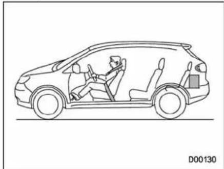
natural_image
Line drawing of a car interior view showing driver and passenger (no text or symbols)Vehicle capacity weight of the vehicle is 1,157 lbs (525 kg), which is indicated on the vehicle placard with the statement "The combined weight of occupants and cargo should never exceed 525 kg or 1,157 lbs".
Forexample, if the vehicle has one
occupantweighing154lbs(70kg) pluscargoweighing882lbs(400 kg).
- Calculatethetotalweight.
Total weight
$$ \begin{array}{l} = \frac {1 5 4 \text { lbs (70 kg) }}{(\text { Occupant })} + \frac {8 8 2 \text { lbs (400 kg) }}{(\text { Cargo })} \ = 1, 0 3 6 \text { lbs (470 kg) } \ \end{array} $$
- Calculatetheavailableloadcapacity by subtracting the total weight from the vehicle capacity weight of 1,157 lbs (525 kg).
Available Load Capacity
$$ \begin{array}{l} = \frac {1 , 1 5 7 \text { lbs }}{(5 2 5 \text { kg })} - \frac {1 , 0 3 6 \text { lbs }}{(4 7 0 \text { kg })} \frac {(V e h i c l e}{(T o t a l w e i g h t)} \ = 1 2 1 \text { lbs (55 kg) } \ \end{array} $$
- Theresultofstep2showsthata further121lbs(55kg)ofcargocan becarried.
Example1B
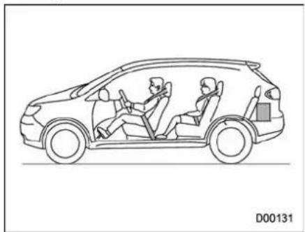
natural_image
Line drawing of a car interior view showing driver and passenger (no text or symbols)Forexample,ifapersonweighing 176lbs(80kg)nowentersthe samevehicle(bringingthenumber ofoccupantstotwo),the calculationsareasfollows.
- Calculatethetotalweight.
Total weight
$$ \begin{array}{l} = \frac {1 5 4 \text { lbs (70 kg) } + 1 7 6 \text { lbs (80 kg) }}{(\text { Occupant })} \ + \frac {8 8 2 \text { lbs (400 kg) }}{(\text { Cargo })} \ = 1, 2 1 2 \text { lbs (550 kg) } \ \end{array} $$
- Calculatetheavailableloadcapacity.
Available Load Capacity
| = | 1,157 lbs(525 kg) | - | 1,212 lbs(550 kg) |
| (Vehicle capacity weight) | (Total weight) |
=-55 lbs (-25 kg)
- Thetotalweightnowexceeds thecapacityweightby55lbs(25 kg), sothecargoweightmustbe reducedby55lbs(25kg)ormore.
Example2A
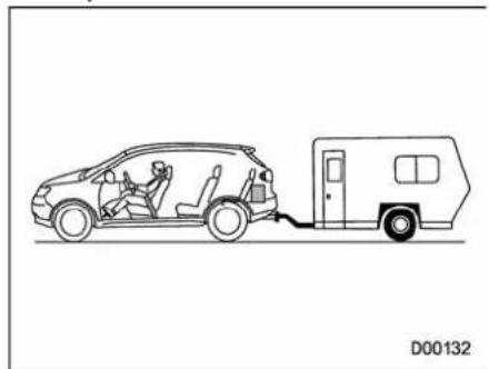
natural_image
Line drawing of a car connected to a small vehicle via cable, no text or symbols presentVehiclecapacityweightofthe
vehicleis1,157lbs(525kg),which isindicatedonthevehicleplacard withthestatement"Thecombined weightofoccupantsandcargo shouldneverexceed525kgor 1,157lbs".
Forexample, the vehicle has one occupant weighing 165 lbs (75 kg) plus cargoweghing 705 lbs (320 kg). In addition, the vehicle is fitted with atraler hitch weighing 22 lbs (10 kg), to which is attached a trailer weighing 1,764 lbs (800 kg). 10% of the trailer weight is applied to the trailertongue (i.e. Tongue load = 176 lbs (80 kg)).
- Calculatethetotalweight.
Total weight
$$ \begin{array}{l} = \frac {1 6 5 \text { lbs (75 kg) }}{(\text { Occupant })} + \frac {7 0 5 \text { lbs (320 kg) }}{(\text { Cargo })} \ + \frac {2 2 \text { lbs (10 kg) }}{\text {(Trailer hitch)}} + \frac {1 7 6 \text { lbs (80 kg) }}{\text {(Tongue load)}} \ = 1, 0 6 9 \text { lbs (485 kg) } \ \end{array} $$
- Calculatetheavailableloadcapacity.
Available Load Capacity
| = | 1,157 lbs(525 kg) | - | 1,069 lbs(485 kg) |
| (Vehicle capacity weight) | (Total weight) |
= 88 lbs (40 kg)
- Theresultofstep2showsthata further88lbs(40kg)ofcargocan becarried.
Example2B
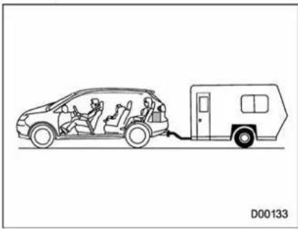
natural_image
Line drawing of a car with driver and crew, connected to a small vehicle (no text or symbols)Forexample, ifapersonweighing 143lbs(65kg) andachildweighing
-CONTINUED-
40lbs(18kg)nowenterthesame vehicle(bringingthenumberof occupantstothree),andachild restraintsystemweighing11lbs(5 kg)isinstalledinthevehicleforthe childtouse,thecalculationsareas follows.
- Calculatethetotalweight.
Total weight
| = 165 lbs(75 kg) + 143 lbs(65 kg) + 40 lbs(18 kg)(Occupant) |
| + 11 lbs (5 kg)(Child restraint) + 705 lbs (320 kg)(Cargo) |
| + 22 lbs (10 kg)(Trailer hitch) + 176 lbs (80 kg)(Tongue load) |
| = 1,263 lbs (573 kg) |
- Calculatetheavailableloadcapacity.
Available Load Capacity
| = 1,157 lbs(525 kg) / (Vehicle capacity weight) = -105 lbs (-48 kg) | - 1,263 lbs(573 kg) / (Total weight) |
- Thetotalweightnowexceeds thecapacityweightby105lbs(48 kg), sothecargoweightmustbe reducedby105lbs(48kg)ormore.
■ Determiningcompatibility of tire and vehicle load capacities
Thesumoffourtires' maximum loadratingsmustexceedthemax- imumloaded vehicle weight ("GVWR").Inaddition,sumofthe maximumloadratingsoftwofront tiresandoftworeartiresmust exceed each axle's maximum loadedcapacity("GAWR").Original equipmenttiresaredesignedto fulfillthoseconditions. The maximumloaded vehicle weightisreferredtoGrossVehicle
WeightRating(GVWR).Andeach axle's maximum loaded capacity is referred to Gross Axle Weight Rating (GAWR). The GVWR and each axle's GAWRareshown the vehicle certification label affixed to the driver's door.
TheGVWRandfrontandrear GAWRsaredeterminedbynotonly themaximumloadratingoftiresbut alsoloadedcapacitiesofthevehicle'ssuspension, axles andother partsofthebody.
Therefore, this mean that the vehicle cannot necessarily be loaded up to the tire's maximum load rating on the tiresidewall.
■Adversesafetyconsequencesooverloadingon handlingandstoppingand ontires
Overloadingcouldaffectvehicle handling, stopping distance, vehicle and tireasshowninthefollowing. This could lead to an accident and possibly result in severe personal
injury.
•Vehiclestabilitywilldeteriorate.
- Heavy and/or high-mounted loadscouldincreaseetheriskof rollover.
- Stoppingdistancewillincrease.
- Brakescouldoverheatandfail.
- Suspension, bearings, axles and other part of the body could break orexperience accelerated wear that will shorten vehicle life.
•Tirescouldfail.
•Treadseparationcouldoccur.
•Tirecouldseparatefromitsrim.
■StepsforDeterminingCorrectLoadLimit
- Locatethestatement "The combined weight of occupants and cargoshould never exceed XXX pounds" on your vehicle's placard.
- Determinethecombinedweight ofthedriverandpassengersthat willberidinginyourvehicle.
-
Subtract the combined weight of the driver and passengers from XXXkilograms or XXXpounds.
-
Theresultingfigureequalsthe availableamountofcargoand luggageeloadcapacity. Forexample, ifthe "XXX" amountequals 1,400lbs(635kg) and therewillbe five-150lbs(68kg) passengers in your vehicle, the amount of available cargo and luggageeload capacity is 650 lbs. (1,400 - 750 (5 × 150) = 650lbs).
- Determinethecombinedweight of luggage and cargobeing loaded on the vehicle. That weight may not safely exceed the available cargo and luggageload capacity calculated in Step 4.
- If your vehicle will be towing a trailer, load from your trailer will be transferred to your vehicle. Consult this manual to determine how this reduces the available cargo and luggage load capacity of your vehicle.
Uniformtirequalitygrading standards
This information indicates the relative performance of passenger car tires in the area of treadwear, traction, and temperature resistance. This is to aid the consumer in making an informed choice in the purchase of tires.
Qualitygradescanbefoundwhere applicable on the tire sidewall betweenreadshoulderandmaximumsectionwidth.Forexample:
Treadwear200TractionAATemperatureA
The quality grades apply tonew pneumatic tires for use on passen- gercars. However, they donot apply to deeptread, wintertype snowtires, space-saverortemporary uses spare tires, tires with nominal rim diameters of 12 inches or less, ortosomelimited produc-tion tires.
Allpassengercartiresmustcon-
-CONTINUED-
formtoFederalSafetyRequirementsinadditiontothesegrades.
Treadwear
Thetreadweargradeisacomparativeratingbasedonthewearrateof thetirewhentestedundercontrolledconditionsonaspecified governmenttestcourse. Forexample, atiregraded150 wouldwearoneandone-half(1-1/2)timesaswellonthegovernmentcourseasatiregraded100. Therelativeperformanceoftires dependsupontheactualconditions oftheiruse, however, and may departsignificantlyfromthenorm duetovariationsindrivinghabits, servicepracticesaddifferencesin roadcharacteristicsandclimate.
■TractionAA,A, B,C
Thetractiongrades, from highest to lowest, are AA, A, B and C. Those grades represent the tire's ability to stop on wet pavement as measured under controlled conditions spe cifiedgovernmenttestsurfacesof asphaltandconcrete.Atiremarked Cmayhavepoortractionperformance.

WARNING
Thetractiongradeassignedto thistireisbasedonstraight-aheadbrakingtractiontests, anddoesnotincludeacceleration,cornering,hydroplan-ing,or peaktraction characteristics.
■TemperatureA, B,C
ThetemperaturegradesareA(the highest),B,andC,representingthe tire'sresistancetothegenerationof heatanditsabilitytodissipateheat whentestedundercontrolledconditionsonaspecifiedindoorlaboratorytestwheel.Sustainedhigh temperaturecancausethematerial ofthetiretodegenerateandreduce tirelife,andexcessivetemperature canleadtosuddentirefailure.The
gradeCcorrespondstoalevelof performancewhichall passenger cartiresmust meetunderthe FederalMotorVehicleSafetyStandardsNo. 109.Grades Band A represent higherlevels ofperformanceonthelaboratorytestwheel thantheminimumrequiredbylaw.

WARNING
Thetemperaturegradeforth this tire is established for atire that is properly inflated and not overloaded. Excessive speed, underinflation, orecessive loading, either separately or in combination, can cause heat buildup and possible tire failure.
Reportingsafetydefects (U.S.A.)
If you believethat your vehicle has a defect which could cause a crash or could cause injury or death, you should immediately inform the National Highway Traffic Safety Administration (NHTSA) in addition to notifying Subaru of America, Inc. If NHTSA receives similar complaints, it may open an investigation, and if it find that as safety defect exists in a group of vehicles, it may order a recall and remedy campaign. However, NHTSA cannot become involved in individual problems between you, your dealer, or Subaru of America, Inc. To contact NHTSA, you may call the Vehicle Safety Hotlinetoll-free at 1-888-327-4236 (TTY: 1-800-424-9153); go to http://www.safercar.gov; or write to: Administrator, NHTSA, 400 Seventh Street, SW., Washington,
DC 20590. You can also obtain other information about motor vehicle safety from http://www.safercar.gov.
| -1.5 | -1.5 | -1.5 | -1.5 |
Index
14-2Index
A
ABS(Anti-lockBrakeSystem)....7-20
Warninglight....3-15,7-21
Accessories....5-2,11-40
Accessorypoweroutlet....6-10
Activeheadrestraint....1-6
Aircleanerelement....11-14
Airconditioner
Automaticclimatecontrolsystem....4-5
Airfiltrationsystem....4-11
Airflow....4-2
Airflowmodeselection....4-3
Airflowselection
Automaticclimatecontrolsystem....4-8
Alarmsystem....2-16
All-WheelDrivewarninglight....3-18
Aluminumwheel....11-30
Cleaning....10-3
Antennasystem....5-2
Anti-lockBrakeSystem(ABS)....7-20
Armingthesystem....2-17
Armrest....1-13
ATOILTEMPwarninglight....3-13
Audio
Antennasystem....5-2
Auxiliaryinputjack....5-28
Controlbutton....5-26
Set....5-3
Auto-dimmingmirror/compass....3-38,3-41
Automaticclimatecontrolsystem....4-5
Automatictransmission....7-12
Capacities....12-3
Fluid....11-16
MANUALmode....7-16
Oiltemperaturewarninglight(ATOILTEMP)......3-13
Selectlever....7-13
Shiftlockfunction....7-14
Shiftlockrelease....7-14
SPORTmode....7-18
Automatic/EmergencyLockingRetractor(A/ELR)....1-18
B
Battery....11-37
Drainagepreventionfunction....2-6
Jumpstarting....9-12
Replacement(remotekeylessentrysystem)......2-11
Boosterseat....1-37
Bottleholder....6-9
Brake
Assist 7-19
Booster....7-19,11-21
Fluid....11-20
Padandlining....11-23
Parking....7-29,11-23
Pedal....11-22
System....7-19
Brakepedal
Freeplay....11-22
Reservedistance....11-22
Brakesystem....7-19
Warninglight....3-16
Braking....7-19
Tips....7-19
Breaking-inofnewbrakepadsandlinings....11-23
Bulb
Chart....12-8
Replacing....11-40
C
Capacities....12-3
Cargoarea
Cover....6-14
Light....6-3
Tie-downhooks....6-16
Catalyticconverter....8-3
Center
Console....6-6
Ventilators....4-4
Changing
Coolant....11-12
Flattire....9-6
Oilandoilfilter....11-8
Chargewarninglight....3-13
CHECKENGINEwarninglight/Malfunctionindicator lamp....3-12
Checking
Brakepedalfreeplay....11-22
Brakepedalreservedistance....11-22
Coolantlevel....11-11
Fluidlevel(automatictransmissionfluid)....11-16
Fluidlevel(brakefluid)....11-20
Fluidlevel(powersteeringfluid)....11-19
Fluidlevel(washerfluid)....11-32
Oillevel(engineoil)....11-7
Oillevel(frontdifferentialgearoil)....11-17
Oillevel(reardifferentialgearoil)....11-18
Childrestraintsystems....1-31
Installationofaboosterseat....1-37
InstallationwithA/ELRseatbelt....1-34
Lowerandtetheranchorages....1-38
Toptetheranchorages....1-41
Childsafety....5
Locks....2-21
Chime
Key....3-4
Light....3-26
Seatbelt....1-18,3-10
Chromeplatedwheels....11-31
Cleaning
Aluminumwheels....10-3
Interior....10-5
Ventilationgrille....4-10
Climatecontrolsystem
Automatic....4-5
Clock....3-21
Coathook....6-12
Coolant....11-11
Coolingsystem....11-11
Corrosionprotection....10-4
Cruisecontrol....7-30
Indicatorlight....3-20,7-33
Setindicatorlight....3-21,7-33
14-4Index
Cupholder....6-8
Front passenger's 6-8
Rearseat(5-seatermodels)/Second-rowseat (7-seater models) passenger's 6-9
Third-rowseat(7-seatermodels)....6-9
D
Daytimerunninglightsystem....3-27
Differentialgearoil
Front....11-17
Rear....11-18
Dimensions....12-2
Disarmingthealarmsystem....2-18
Discbrakepadwearwarningindicators....7-20
Domelight....6-2,11-46
Door
Locks....2-5
Openwarninglight....3-17
Steplight....11-47
Drivebelts....11-15
Driving
All-WheelDrivewarninglight....3-18
AWDvehicles....8-4
Carphone/cellphone....7
Drinking....6
Drugs....6
Foreigncountries....8-4
Pets....7
Snowyandicyroads....8-9
Tips....8-2,8-4
Tiredorsleepy....7
Winter....8-7
E
Electricalsystem....12-3
ElectronicBrakeForceDistribution(EBD)system...3-17,7-22
EmergencyLockingRetractor(ELR)....1-18
Engine
Compartmentoverview....11-6
Coolant....11-11
Exhaustgas(carbonmonoxide)....5,8-2
Hood....11-4
Oil 11-7
Overheating....9-14
Starting....7-7
Stopping....7-8
Exteriorcare....10-2
F
Flattires....9-6
Floormat....6-13
Fluidlevel
Automatictransmission....11-16
Brake....11-20
Powersteering....11-19
Foglight
Bulb....11-43
Indicatorlight....3-21
Switch....3-32
Foldingmirrorswitch....3-43
Front
Differentialgearoil....11-17
Foglight....3-32,11-43
Foglightindicatorlight....3-21
Seatbeltpretensioners....1-28
Turnsignallight....11-43
Frontseats....1-2
Forwardandbackwardadjustment....1-3
Powerseat....1-3
Reclining....1-3
Fuel....7-2
Economyhints....8-2
Fillerlidandcap....7-3
Gauge....3-8
Requirements....7-2
Fuses....11-38
Mainfuse....11-39
Fusesandcircuits....12-5
G
GAWR(GrossAxleWeightRating)......8-12
Glovebox....6-6
GVWR(GrossVehicleWeightRating)......8-12
H
Hazardwarningflasher....3-5,9-2
Headrestraintadjustment
Frontseat....1-5
Rear(5-seatermodels)/Second-row
(7-seatermodels)....1-11
Third-row....1-15
Headlight
Beamleveler....3-29
Bulbreplacement....11-40
Controlswitch....3-26
Flasher....3-27
Indicatorlight....3-21
Highbeamindicatorlight....3-20
High/lowbeamchange(dimmer)....3-27
HomeLink®WirelessControlSystem....6-17
Hook
Coat....6-12
Convenienttie-down....6-16
Shoppingbag....6-13
Towingandtie-down....9-15
Horn....3-44
Hoseandconnections....11-11
|
Ignitionswitch....3-3
Light....3-4
Illuminatedentry....2-10
Illuminationbrightnesscontrol....3-28
Immobilizer....2-3
Indicatorlight(securityindicatorlight)....2-4,3-19
Indicatorlight
Cruisecontrol....3-20,7-33
Cruisecontrolset....3-21,7-33
Frontfoglight....3-21
Headlight....3-21
Highbeam....3-20
Immobilizer....3-19
Security....2-4,3-19
Selectlever/Gearposition....3-20
14-6Index
SPORTmode....3-20
TractioncontrolsystemOFF....7-25
Turnsignal....3-20
VehicleDynamicsControlOFF....3-18
VehicleDynamicsControloperation....3-18,7-25
Interiorlights....6-2
J
Jackandjackhandle....9-19
Jack-uppoint....9-6
Jumpstarting....9-12
K
Key....2-2
Number....2-2
Reminderchime....3-4
Replacement....2-4
Keylessentrysystem....2-8
L
Leatherseatmaterials....10-5
Licenseplatelight....11-45
Light
Back-up(Stationwagon)....11-44
Cargoarea....6-3,11-48
Controlswitch....3-26
Dome....6-2,11-46
Doorstep....11-47
Frontfog....3-32,11-43
Ignitionswitch....3-4
Licenseplate....11-45
Map....6-3,11-47
Rearcombination....11-43
Reargate....6-3
Turnsignal....3-28,11-43
Vanitymirror....6-5,11-47
Loadingyourvehicle....8-11
Lowfuelwarninglight....3-8,3-17
Lowtirepressurewarninglight....3-14
Lowerandtetheranchorage....1-38
Lumbarsupport....1-6
M
Mainfuse....11-39
Maintenance
Precautions....11-3
Schedule....11-3
Seatbelt....1-28
Tools....9-19
Malfunctionindicatorlamp(checkenginewarninglight)...3-12
Maplight....6-3,11-47
Maximumloadlimits....8-20
Metersandgauges....3-5
Mirrors....3-38
Moonroof....2-25
Multifunctiondisplay....3-23
N
Newvehiclebreak-indriving....8-2
0
Odometer....3-6
Oilfilter....11-8
Oillevel Engine....11-7
Frontdifferentialgear....11-17
Reardifferentialgear....11-18
Oilpressurewarninglight....3-13
On-pavementandoff-roaddriving....8-5
Outside Mirrordefogger....3-43
Mirrors....3-42
Temperatureindicator....3-22
Overheadconsole....6-8
Overheatingengine....9-14
P
Parking Brake....7-29
Brakestroke....11-23
Light....11-42
Lightswitch....3-32
Tips....7-30
Periodicinspections....8-4
Petrolfuel....7-2
Power Doorlockingswitch....2-7
Outsidemirrors....3-43
Seat....1-3
Steering....7-18
Steeringfluid....11-19
Windows....2-21
Precautionsagainstvehiclemodification....1-31,1-72
Rear
Airconditioner....4-8
Combinationlights....11-43
Differentialgearoil....11-18
Gate....2-24,9-18
Gatelight....6-3,11-45
Seats 1-7
Turnsignallight....11-43
Reardifferential Oiltemperaturewarninglight....3-14
Rearseat Foldingdown....1-10 Reclining....1-9
Rearviewcamera....6-22
Rearwindow Defoggerbutton....3-37 Wiperandwasherswitch....3-35 Wiperblades....11-35
Recommended Automatictransmissionfluid....11-17
Brakefluid....11-21
Engineoil....11-9,11-10
Frontdifferentialgearoil....11-18
Powersteeringfluid....11-20
Reardifferentialgearoil....11-19
Sparkplugs....11-15
Refueling....7-3
Remoteenginestartsystem....7-8
14-8Index
Remotekeylessentrysystem....2-8
Replacement
Brakepadandlining....11-22
Wiperblades....11-33
Replacing
Aircleanerelement....11-14
Battery(remotekeylessentrysystem)....2-11
Losttransmitters(remotekeylessentrysystem)......2-12
Replacingbulbs....11-40
Back-uplight(Stationwagon)....11-44
Cargoarealight....11-48
Domelight....11-46
Doorsteplight....11-47
Frontfoglight....11-43
Frontturnsignallight....11-43
Headlight....11-40
Licenseplatelight....11-45
Maplight....11-47
Parkinglight....11-42
Rearcombinationlight....11-43
Reargatelight....11-45
Vanitymirrorlight....11-47
Rockingthevehicle....8-11
Roofmoldingandcrossbar....8-16
Roofrailandcrossbar....8-13
S
Safety
Precautionswhendriving....4
Symbol....2
Warnings....2
Seat
Fabric....10-5
Front....1-2
Heater....1-7
Memoryfunction....1-4
Power....1-3
Seatbelt....4,1-16
Fastening....1-19
Maintenance....1-28
Pretensioners....1-28
Safetytips....1-16
Warninglightandchime....1-18,3-10
Security
Alarmsystem....2-16
IDplate....2-3
Immobilizer....2-3
Indicatorlight....2-4,3-19
Shocksensors....2-20
Selectlever....7-13
Positionindicator....3-20
Shiftlockfunction....7-14
Shiftlockrelease....7-14
Shocksensors....2-20
Shoppingbaghook....6-13
Snowtires....8-10,11-24
Snowyandicyroads....8-9
Soundingapanicalarm....2-11
Sparetire....9-2
Sparkplugs....11-15
Specifications....12-2
Speedometer....3-6
SPORTmode....7-18
SPORTmodeindicatorlight....3-20
SRS
Curtainairbag....1-60
Frontalairbag....1-49
Sideairbag....1-60
SRSairbag(SupplementalRestraintSystemairbag)...4,1-45
SRSairbagsystem
Monitors....1-71
Servicing....1-72
Warninglight....3-11
Startingtheengine....7-7
Stateemissiontesting(U.S.only)....7-5
Steeringwheel
Power....7-18
Tilt....3-44
Stoppingtheengine....7-8
Storagecompartment....6-6
Sunshade....2-27
Sunvisors....6-4
SupplementalRestraintSystemairbag(SRS)....1-45
Syntheticleatherupholstery....10-5
T
Tachometer....3-7
Temperaturegauge....3-9
Temperaturewarninglight
ATOILTEMP....3-13
Reardifferentialoil....3-14
Temporarysparetire....9-5
Tether(childrestraintsystem)....1-38,1-41
Tie-downhooks....9-15
Tiltsteeringwheel....3-44
Tire....11-24,12-3
Chains....8-11
Inspection....11-25
Pressuresandwear....11-26
Replacement....11-29
Rotation....11-29
Types....11-24
Tirepressuremonitoringsystem(TPMS).....7-28,9-11,11-24
Warninglight....3-14
Tiresandwheels....11-24
Tools....9-19
Toptetheranchorages....1-38, 1-41
Towing....9-14
Allwheelsontheground....9-17
Flat-bedtruck....9-17
Hooks....9-15
Weight....8-20
TractionControlsystem
OFFindicatorlight....3-18,7-25
OFFswitch....7-27
Trailer
Connecting....8-18
Hitch....8-18,8-23
Towing....8-20
Towingtips....8-26
Tripmeter....3-7
Turnsignal
Indicatorlights....3-20
Lever....3-28
14-10Index
U
Under-floorstoragecompartment....6-16
V
Valetmode....2-18
Vanitymirror....6-5,11-47
Vehicle
Capacityweight....8-12
Identification....12-11
Symbols....3
VehicleDynamicsControl
Operationindicatorlight....3-18,7-25
System....7-23
Warninglight....3-18,7-25
Ventilator....4-2
W
Warningandindicatorlights....3-9
Warningchimes
Seatbelt....1-18,3-10
Warninglight
ABS....3-15,7-21
All-WheelDrive....3-18
ATOILTEMP....3-13
Brakesystem....3-16
Charge....3-13
CHECKENGINE....3-12
Dooropen....3-17
Lowfuel....3-8,3-17
Lowtirepressure....3-14
Oilpressure....3-13
Reardifferentialoiltemperature....3-14
Seatbelt....1-18,3-10
SRSairbagsystem....3-11
VehicleDynamicsControl....3-18,7-25
Windshieldwasherfluid....3-18
Warranties....1
Warrantiesandmaintenance....8-20
Washing....10-2
Waxingandpolishing....10-3
Wearindicators....11-28
Wheel
Alignment....12-4
Aluminum....11-30
Balance....11-28
Chromeplatedwheels....11-31
Replacement....11-30
Windows....2-21
Windshield
Washerfluid....11-32
Wiperandwasherswitches....3-34
Wiperblades....11-34
Wiperdeicer....3-36
Winter
Driving....8-7
Tires....8-10,11-24
Wiperandwasher....3-33
Wiperdeicer....3-36
| 100 | |
| 100 | 100 |
| 200 | 100 |
| 300 | 100 |
| 400 | 100 |
| 500 | 100 |
| 600 | 100 |
| 700 | 100 |
| 800 | 100 |
| 900 | 100 |
| 1000 | 100 |
Compasscalibrationzones
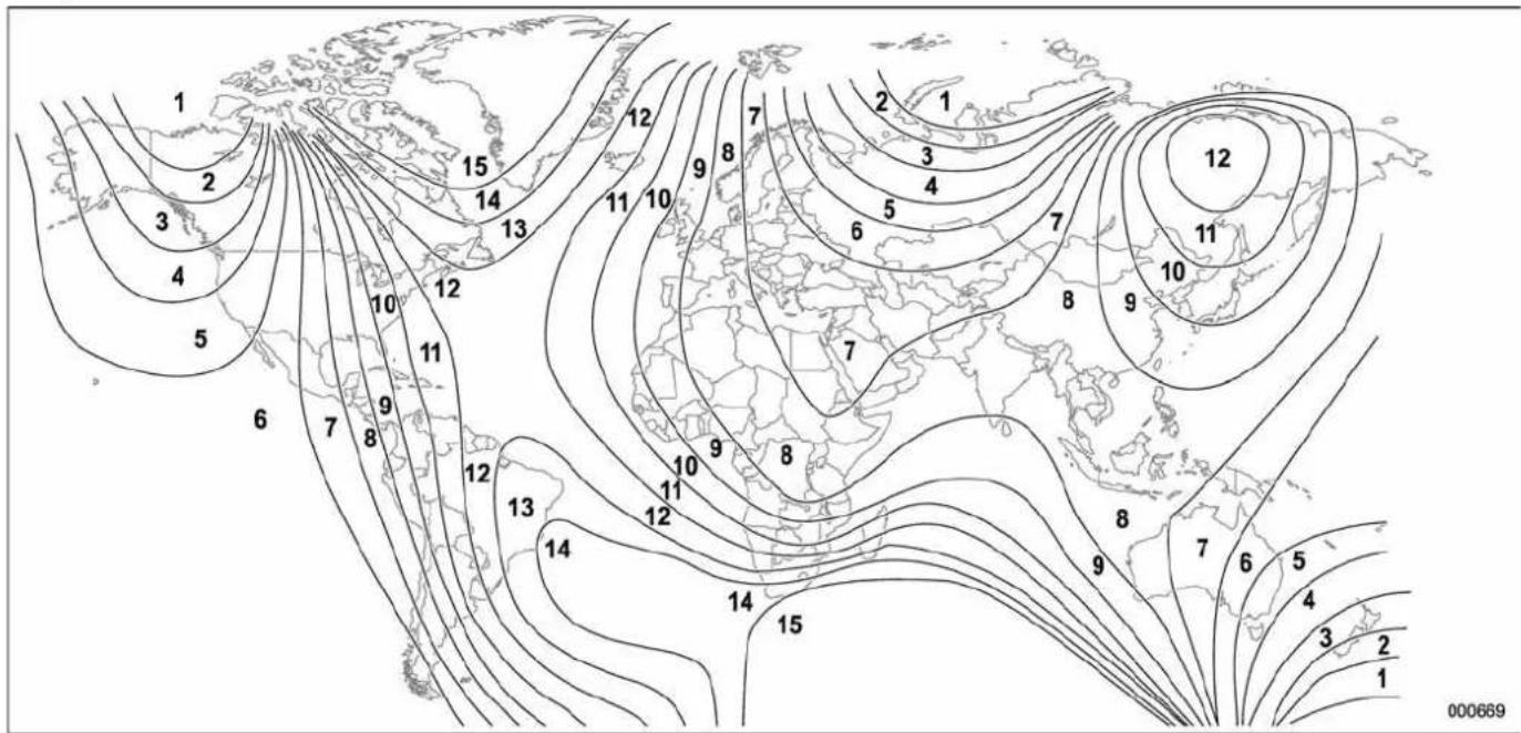
contour
| Region | Value | | -------------- | ----- | | North America | 1 | | Europe | 2 | | Asia | 3 | | Africa | 4 | | South America | 5 | | Australia | 6 | | Antarctica | 7 | | North America | 8 | | Europe | 9 | | Asia | 10 | | Africa | 11 | | South America | 12 | | Australia | 13 | | Antarctica | 14 | | North America | 15 | | Europe | 16 | | Asia | 17 | | Africa | 18 | | South America | 19 | | Australia | 20 | | Antarctica | 21 |GASSTATIONREFERENCE
Fuel
Useunleadedgasolinewithanoctaneratingof87AKlor higher.
■ Fueloctanerating
This octanerating is the average of the Research Octane and Motor Octan numbers and is commonly referred to as the Anti Knock Index (AKI). Refer to "Fuel octane rating" 7-2.
Fuelcapacity
16.9USgal(64liters,14.1Impgal)
Engineoil
Useonlythefollowingoils.
- ILSACGF-4, which can be identified with the ILSAC certification mark (Starburstmark)
- orAPIclassificationSMwiththewords"ENERGYCONSERVING"
For the complete viscosity requirements, referto the following sections.
- "Recommended grade and viscosity" 11-9
- "Recommendedgradeandviscosityunderseveredriving conditions" 11-10
■Engineoilcapacity
6.7USqt(6.3liters,5.5Impqt)
Coldtirepressure
| TiresizeP255/55R18104H | ||
| Wheelsize18 × 8JJ | ||
| Pressure | Front | 33psi(230kPa,2.3kgf/cm ^2 ) |
| Rear | 32psi(220kPa,2.2kgf/cm ^2 ) | |
| Temporarysparetire | Size | T165/80R17 |
| Pressure | 60psi(420kPa,4.2kgf/cm ^2 ) | |


- Safety Warnings
- WARNING
- CAUTION
- NOTE
- Before Use
- Read this manual first
- Avoid operating the monitor while driving
- Look at the monitor only when necessary
- Keep the volume low enough for you to hear outside sounds
- Never disassemble or modify the monitor
- Do not continue using the monitor if it malfunctions
- If the monitor gets contaminated, emits smoke or an odd smell, stop using it
- ■About the monitor
- Control Button Names
- DEST
- MENU
- MAP
- ZOOM
- AUDIO
- INFO
- 7
- Displaying Vehicle Information Screen
- Displaying Vehicle Information and Programming Vehicle System Functions
- Displaying fuel consumption information and programming for the automatic alarm display
- ■Displaying fuel consumption information
- ■Programming automatic alarm display for low remaining fuel level
- 1
- Select
- 2
- 3
- Displaying, retaining, and erasing driving record data
- ■Displaying driving record data
- ■Retaining driving record data
- 4
- 5
- ■Erasing driving record data
- ■Displaying retained driving record data list
- ■Retaining driving record data while viewing a retained driving record data list
- ■Erasing driving record data while viewing a retained driving record data list
- Displaying three meters
- Select 999.
- Maintenance schedule
- ■Programming maintenance schedule
- When a vehicle maintenance schedule is programmed
- Programming vehicle system functions
- ■Programming display and answerback beep
- Select the display and beep programming screen will appear.
- BEEP
- OUT TEMP
- AUDIO DISP
- DISP TIME
- This completes the procedure.
- ■ Touch panel sensing position adjustment
- ■Keyless entry system programming
- LOCK SIGNAL
- RESET
- ■Programming other vehicle system functions
- KEY ALERT
- ROOMLAMP (interior light)
- DEFOGGER
- DEICER
- ■Alarm system and shock sensor
- ALARM
- DELAY
- SHOCK SENSOR
- The calculator functions
- The calendar functions
- ■Displaying calendar
- Select CALENDAR.
- ■Adding a memo
- ■Deleting a memo
- Displaying Satellite Radio Source
- Adjusting Brightness/Contrast
- FCC WARNING
- Foreword
- Contents
- System Components
- Basic Operations
- What You Can Enjoy with Your Rear Seat Entertainment System
- Display
- ■ How to open and close the display
- - Keeping the display clean
- Remote Control
- ■ How to use the remote control
- ■ Replacing the battery
- Wireless Headphones
- ■ Replacing the batteries
- DVD Player
- Precautions to Observe When Handling Discs
- Types of Discs Playable with the Rear Seat Entertainment System
- DVD video discs
- Copyright
- Playing Discs
- Playing DVD Video Discs
- ■ Starting playback
- ■ Stopping playback
- ■ Pausing
- ■ Fast-forwarding
- Fast-reversing
- Method using screen and remote control:
- Method using remote control alone:
- ■ Skipping chapters forward
- ■ Skipping chapters backward
- ■ Title search
- ■ Skipping to a predetermined screen
- ■ Displaying each disc's menu on the screen
- Method using the remote control alone:
- ■ Changing the audio language
- ■ Changing the subtitle language
- ■ Image angle selection on multi-angle recorded scenes
- ■ Selecting a dynamic range control setting
- Playing Video CDs
- ■ Skipping tracks forward
- NOTE (Ver 2.0 video CD only)
- ■ Skipping tracks backward
- ■ Skipping to a predetermined screen (Ver 2.0 video CD only)
- ■ Sound channel (MAIN/SUB) selection
- Playing Music CDs
- ■ Repeat playback
- ■ Random playback
- Scan
- Initial Settings
- Setting DVD/Audio/Subtitle Language
- Setting the Angle Mark Display
- Setting the Viewer Restriction Level
- ■ Password registration
- Connecting External Devices to Your Rear Seat Entertainment System
- Adjusting Display Conditions and Selecting Display Mode
- Display Condition Adjustment
- ■ Adjusting method
- Display Mode Selection
- ■ Selecting method
- Error Messages
- Cause:
- WarrantiesforCanada
- HowtousethisOwner's Manual
- ■UsingyourOwner'sManual
- Chapter1: Seat, seatbelt and SRS airbags
- Chapter2:Keysanddoors
- Chapter3: Instrumentsandcontrols
- Chapter4:Climatecontrol
- Chapter5:Audio
- Chapter6: Interiorequipment
- Chapter7: Starting and operating
- Chapter8:Drivingtips
- Chapter9: Incaseofemergency
- Chapter10: Appearancecare
- Chapter11: Maintenance and service
- Chapter12:Specifications
- Chapter13: Consumerinformation and Reportingsafetydefects
- Chapter14:Index
- ■ Safetywarnings
- Safetyprecautionswhen driving
- ■ SeatbeltandSRSairbag
- Childsafety
- ■Engineexhaustgas(carbon monoxide)
- ■ Drinkinganddriving
- Drugsanddriving
- ■ Drivingwhentiredorsleepy
- ■ Carphone/cellphone and driving
- ■ Modification of your vehicle
- ■ Drivingvehicle equipped withanavigationsystem
- ■ Drivingwithpets
- Tirepressures
- ■ Californiaproposition65 warning
- ■ On-pavementandoff-road driving
- Illustratedindex
- Interior
- ▼Passengercompartmentarea
- ■ Combinationmeter
- ▼U.S.-spec.models
- Cargoarea
- ▼7-seatermodels
- Functionsettings
- Seat, seatbelt and SRS airbags
- 1-2 Seat, seatbelt and SRSairbags
- Frontseats
- Powerseat
- 1-4 Seat, seatbelt and SRSairbags
- ■ Memoryfunction(driver's seat-ifequipped)
- ▼Retrievalofseatposition
- Toraise:
- Tolower:
- Toremove:
- Toinstall:
- 1-6 Seat, seatbelt and SRSairbags
- 1-8 Seat,seatbeltandSRSairbags
- 1-10 Seat,seatbeltandSRSairbags
- ■ Foldingdowntheseatback
- ■Headrestraintadjustment
- 1-12 Seat,seatbeltandSRSairbags
- ■Accesstothethird-rowseat
- 1-14 Seat, seatbelt and SRSairbags
- 1-16 Seat,seatbeltandSRSairbags
- Seatbelts
- ■ Seatbeltsafetytips
- THESRSAIRBAG.
- ▼Infantsorsmallchildren
- ▼Children
- 1-18 Seat,seatbeltandSRSairbags
- EmergencyLockingRetractor(ELR)
- ■Automatic/EmergencyLockingRetractor(A/ELR)
- ■ Seatbeltwarninglight andchime
- ▼ Operation
- ■Fasteningthe seatbelt
- 1-20 Seat,seatbeltandSRSairbags
- ▼Frontseatbelts
- 1-22 Seat,seatbeltandSRSairbags
- ▼Rearseatbelts(5-seatermodels)/Second-rowseatbelts(7-seater models)—excludingcenterseatbelt
- Adjusting the shoulder belt anchor height (rearseatsof5-seater models/second-rowseatsof7-seater models)
- 1-24 Seat, seatbelt and SRSairbags
- 1-26 Seat,seatbeltandSRSairbags
- ▼Third-rowseatbelt(7-seatermodels)
- Seatbeltmaintenance
- Frontseatbelt pretensioners
- SRSairbagsystemwarninglight
- 1-30 Seat, seatbelt and SRSairbags
- ■ Systemservicing
- ■Precautionsagainstvehicle modification
- 1-32 Seat,seatbeltandSRSairbags
- ■Wheretoplaceachildre- straintsystem
- A:Frontpassenger'sseat
- B: Rearoutboardseats(5-seatermodels)/second-rowoutboardseats(7-seatermodels)
- C: Rearcenterseat(5-seatermodels)/second-rowcenterseat(7-seatermodels)
- D: Third-rowseat(7-seatermodels)
- ■InstallingchildrestraintsystemswithA/ELRseatbelt
- ■Installingaboosterseat
- creased.
- ■ Installationofchildrestraint systemsbyuseoflowerand tetheranchorages(LATCH)
- 1-40 Seat,seatbeltandSRSairbags
- ■ Toptetheranchorages
- ▼ Tetheranchoragelocation
- 1-42 Seat,seatbeltandSRSairbags
- ▼Tohookthetoptether
- 1-44 Seat, seatbelt and SRSairbags
- \*SRSairbag(Supplemental RestraintSystemairbag)
- ■Yourvehicle'sSRSconfiguration
- 1-48 Seat,seatbeltandSRSairbags
- ■ SUBARUadvancedfrontal airbagsystem
- 1-50 Seat,seatbeltandSRSairbags
- ▼Driver'sSRSfrontalairbag
- ▼Frontpassenger'sSRSfrontalair-bag
- 1-52 Seat,seatbeltandSRSairbags
- ▼Conditionsinwhichfrontpassenger'sSRSfrontalairbagisnot activated
- 1-54 Seat, seatbelt and SRSairbags
- ▼Effectvehiclemodificationsmade forpersonswithdisabilitiesmay haveonSUBARUadvancedfrontal airbagsystemoperation(U.S.only)
- 1-56 Seat,seatbeltandSRSairbags
- ▼Operation
- componentscanbeveryhotasa resultofdeployment.
- 1-58 Seat,seatbeltandSRSairbags
- 1-60 Seat,seatbeltandSRSairbags
- ■ SRSsideairbagandSRS curtainairbag
- frontseat'soccupant.
- 1-64 Seat, seatbelt and SRSairbags
- 1-66 Seat,seatbeltandSRSairbags
- ExamplesofthetypesofaccidentsinwhichtheSRScurtainairbagwillmost likelydeploy.
- 1-68 Seat,seatbeltandSRSairbags
- ExamplesofthetypesofaccidentsinwhichtheSRSsideairbagisunlikelyto deploy.
- ExamplesofthetypesofaccidentsinwhichtheSRScurtainairbagisunlikely todeploy.
- 1-70 Seat,seatbeltandSRSairbags
- 1-72 Seat,seatbeltandSRSairbags
- ■ SRSairbagsystemservicing
- Keys and doors
- 2-2Keysanddoors
- Keys
- ■Keynumberplate
- Immobilizer
- 2-4Keysanddoors
- ■Keyreplacement
- Doorlocks
- ■Lockingandunlockingfrom theinside
- 2-6Keysanddoors
- ■Batterydrainageprevention function
- 2-8Keysanddoors
- ▼Behaviorwithkeylock-inpreventionfunctionoperational
- ▼Behaviorwithkeylock-inpreventionfunctionnon-operational
- Remotekeylessentrysystem
- 2-10Keysanddoors
- ■Illuminatedentry
- ■ Selectingaudiblesignaloperation
- ■Replacingthebattery
- swallowthem.
- 2-12Keysanddoors
- ■ Replacinglosttransmitters
- ▼Programmingthetransmitters
- 2-14Keysanddoors
- ▼Deletingoldtransmittercodes
- 2-16Keysanddoors
- Alarmsystem
- Systemoperation
- ■ Activating and deactivating the alarmsystem
- ■ If you have accidentally triggered the alarmsystem
- ▼Tostopthealarm
- Armingthesystem
- ▼Toarmthesystemusingremote transmitter
- ▼Toarmthesystemusingpower doorlockingswitches
- 2-18Keysanddoors
- ■Disarmingthe system
- ▼Emergencydisarming
- ■ Valetmode
- Passivearming
- Toenterthepassivemode
- Disarmingthesystem
- 2-20Keysanddoors
- ■ Trippedsensoridentification
- ■Shocksensors(dealeroption)
- Example:
- Childsafetylocks
- Windows
- Powerwindows
- 2-22Keysanddoors
- Toopen:
- Toclose:
- 2-24Keysanddoors
- Moonroof(ifequipped)
- 2-26Keysanddoors
- ■ Anti-entrapmentfunction
- Instruments and controls
- Instrumentsandcontrols
- Ignitionswitch
- ■LOCK
- 3-4 Instrumentsandcontrols
- Acc
- ON
- START
- ■ Keyreminderchime
- Ignitionswitchlight
- Metersandgauges
- ■ Combinationmeterillumination
- Speedometer
- ▼Vehiclecommunicationsystem malfunctionindication
- Tachometer
- Warningandindicatorlights
- 3-10 Instrumentsandcontrols
- ■ SRSairbagsystem warninglight
- 3-12 Instrumentsandcontrols
- ■Frontpassenger'sfrontal airbagONandOFFindicators
- ■ CHECKENGINE warninglight/Malfunctionindicatorlamp
- ▼ Ifthelightilluminatessteadily
- Thislightalsoilluminateswhenthefuel fillercapisnottighteneduntilclicks.
- ▼Ifthelightisblinking
- ■Chargewarninglight
- Oilpressurewarning light
- ■ATOILTEMPwarning light
- ▼Automatictransmissioncontrol systemwarning
- ■Reardifferentialoil temperaturewarning light
- ■ Lowtirepressure warninglight
- ■ABSwarninglight
- workproperly.
- Brakesystem warninglight
- immediately.
- ▼Parkingbrakewarning
- ▼Brakefluidlevelwarning
- ▼ElectronicBrakeForceDistribution (EBD)systemwarning
- ■ Lowfuelwarninglight
- 3-18 Instrumentsandcontrols
- ■Windshieldwasher fluidwarninglight
- ■ All-WheelDrivewarninglight
- ■ VehicleDynamics Controloperationindicatorlight
- ■ VehicleDynamics Controlwarninglight/TractionControlsystem OFFindicatorlight
- ▼VehicleDynamicsControlwarning light
- ▼Alarmsystem
- ▼Immobilizersystem
- 3-20 Instrumentsandcontrols
- ■ SPORTmodeindicator light SPORT
- ■ Selectlever/Gearpositionindicator
- ■Turnsignalindicator lights
- ■ Highbeamindicator light
- ■ Cruisecontrolindicatorlight
- Cruisecontrolsetindicatorlight
- ■ Headlightindicator light
- ■ Frontfoglightindicator light
- Clock
- 3-22 Instrumentsandcontrols
- Outsidetemperatureindicator
- Multifunctiondisplay(vehicleswithoutagenuine SUBARUnavigationsystem)
- Lightcontrolswitch
- Headlights
- EDOE firstposition
- secondposition
- ■Daytimerunninglightsystem
- Headlightbeamleveler(if equipped)
- 3-30 Instrumentsandcontrols
- Wiperandwasher
- ■Windshieldwiperandwasher switches
- ▼Rearwiper
- ▼Washer
- Windshieldwiperdeicer
- Rearwindowdefoggerbutton
- Mirrors
- ▼Rearviewimagedisplay
- ▼Auto-dimmingfunction
- ▼Electroniccompassdisplay
- Compasscalibration
- ■TypeCinsidemirror(if equipped)
- ▼Compasscalibration
- 3-42 Instrumentsandcontrols
- ▼Convexmirror(passengerside)
- ▼Outsidemirrordefogger
- thannecessary.
- ▼Powerfoldingmirrorswitch(if equipped)
- Tiltsteeringwheel
- Horn
- Climate control
- 4-2Climatecontrol
- Ventilator
- ▼Airflowmodeselection
- 4-4Climatecontrol
- Automaticclimatecontrol system
- ▼AUTObutton
- Manualmodeoperation:
- 4-6Climatecontrol
- ▼-Defrosterbutton
- ▼ Fanspeedcontroldial
- ▼ A/C-Airconditionerbutton
- 4-8Climatecontrol
- Operatingtipsforheaterand airconditioner
- ■ Efficientcoolingafterparking indirectsunlight
- ■ Lubricationoilcirculationin therefrigerantcircuit
- ■ Checkingairconditioning systembeforesummerseason
- ■Coolinganddehumidifyingin highhumidityandlowtemperatureweatherconditions
- ■ Airconditionercompressor shut-offwhenengineis heavilyloaded
- ■Refrigerantforyourclimate controlsystem
- Airfiltrationsystem
- 4-12Climatecontrol
- Audio
- 5-2Audio
- Antennasystem
- Printedantenna
- ■FMreception
- Installationofaccessories
- Audioset
- 5-4Audio
- TypeA audioset(ifequipped)
- ▼Powerswitchandvolumecontrol
- ▼Toneandbalancecontrol
- ▽Tochangetoneandbalancecontrol modes
- 5-6Audio
- ▼ FM/AMradio
- ▽FM/AMselection button
- ▽Stereoindicator
- Manualtuning
- ∇Seektuning
- Automatictuning(SCAN)
- ▼Selectingpresetstations
- ▼Howtopresetstations
- ▼Satelliteradiomode(ifequipped)
- ▽Siriusatelliteradio
- XMTM satelliteradio
- ▽Satelliteradioreception
- ▽DisplayingsatelliteradiolDoftuner
- ▽Bandselectionbutton
- ▽Channelselection
- Categoryselection
- ▽Channelscan
- ▼Selectingpresetchannels
- ▼Howtopresetchannels
- ▽Displayselection
- ▼Rearseatentertainment
- 5-10Audio
- ▼Toplaybackacompactdisc
- WhenCDisnotintheplayer
- •DONOTINSERTTWODISCSINTO THEDISCINSERTIONSLOTATTHE SAMETIME.
- WhenCDisintheplayer
- ▼TostopplaybackofaCD
- ▼Toselectasongfromitsbeginning
- ▽Forwarddirection
- Backwarddirection
- ▼Fast-forwardingandfast-reversing
- ∇Fast-forwarding
- ∇Fast-reversing
- ▼Folderselection(MP3disc)
- 5-12Audio
- ▼Repeating
- ∇Torepeatthecurrentlyplayingtrack/file(track)
- ∇ To repeat the currently playing folder (MP3disc)
- ▼Random playback
- Non-MP3disc
- MP3disc
- ▼Scan
- ▼Toeject adiscfromtheplayer
- 5-14Audio
- ▼Displayselection(MP3disc)
- ▼Page(track/foldertitle)scroll(MP3 disc)
- TypeBaudioset(ifequipped)
- 5-16Audio
- ▼FM/AMradio
- ▽FM/AMselectionbutton
- Manualtuning
- 5-18Audio
- ▽Seektuning(SEEK)
- Scantuning(SCAN)
- ▽ DisplayingsatelliteradiolDoftuner
- 5-20Audio
- 5-22Audio
- ▼HowtoinsertaCD(s)
- InsertingaCD
- Insertingadiscinadesiredposition
- ▼Loadingallthemagazine(fulldisc loadingmode)
- ▼HowtoplaybackaCDormakea pause
- ▼WhenthereisnoCDinserted:
- ▼WhenthereareCDsloaded:
- ▽Torepeatthecurrentlyplayingtrack/file(track)
- 5-24Audio
- ▽Torepeatthecurrentlyplayingdisc/folder
- ▼ Random playback
- 5-26Audio
- ▼HowtounloadCDsfromtheplayer
- ▽EjectingaCDfromtheplayer
- ▽Ejectingalldiscsfromtheplayer(all discejectionmode)
- Audiocontrolbuttons
- Withradiomodeselected
- WithCDmodeselected
- RearSeatEntertainment (RSE)systemoperation(if equipped)
- Precautionstoobservewhen handlingacompactdisc
- 5-30Audio
- Interior equipment
- 6-2 Interiorequipment
- Interiorlight
- 6-4 Interiorequipment
- ■Vanitymirrorwithlight
- 6-6 Interiorequipment
- Storagecompartment
- Glovebox
- ■ Centerconsolebox
- Cupholder
- ■Frontpassenger'scupholder
- Bottleholders
- 6-10 Interiorequipment
- ance.
- 6-12 Interiorequipment
- Coathook
- Shoppingbaghook
- Floormat
- 6-14 Interiorequipment
- Cargoareacover(if equipped)
- Toremovethecover
- ■Toinstallthecoverhousing
- Convenienttie-downhooks
- Under-floorstoragecompartment
- 5-seatermodels
- 6-18 Interiorequipment
- GaragedooropenerprogrammingintheU.S.A.
- 6-20 Interiorequipment
- ■ Programmingforentrance gatesandgaragedooropen-ersinCanada
- memoryofallthreebuttons.
- ■ Programmingotherdevices
- ■OperatingtheHomeLink® WirelessControlSystem
- ■Reprogrammingasingle HomeLink®button
- ■ ErasingHomeLink®button memory
- ■Incaseaproblemoccurs
- 6-22 Interiorequipment
- ■Howtousetherearview camera
- Helpline
- Starting and operating
- 7-2 Starting and operating
- Fuel
- Fuelrequirements
- ▼Fueloctanerating
- ▼Unleadedgasoline
- ▼Californiafuel
- ▼MMT
- ▼Gasolineforcleanerair
- ■ Fuelfillerlidandcap
- Refueling
- 7-4 Starting and operating
- magetothefuelsystem.
- Stateemissiontesting(U.S. only)
- 7-6 Starting and operating
- Preparingtodrive
- Startingtheengine
- 7-8 Starting and operating
- Stoppingtheengine
- Remoteenginestartsystem (dealeroption)
- ■ Startingyourvehicle
- ■ Remotestartsafetyfeatures
- ■ Enteringthevehiclewhileit isrunningviaremotestart
- ■ Enteringthevehiclefollowingremoteenginestartshutdown
- 7-10 Starting and operating
- ■ Pre-heatingorpre-cooling theinteriorofthevehicle
- Servicemode
- ▼Toengagetheservicemode
- ▼Todisengagetheservicemode
- ■ Remoteenginestarttransmitterprogrammingandprogrammablefeatureoption
- ■ Systemmaintenance
- ▼Changingthebatteries
- 7-12 Starting and operating
- Automatictransmission
- ▼P(Park)
- 7-14 Starting and operating
- ▼R(Reverse)
- ▼N(Neutral)
- ▼D(Drive)
- Whileclimbingagrade
- Shiftlockfunction
- ▼Shiftlockrelease
- ▼Shiftlockreleaseusingtheshift lockreleasebutton
- 7-16 Starting and operating
- ■Drivingtips
- 7-18 Starting and operating
- Powersteering
- Braking
- Brakingtips
- ▼Whenthebrakesgetwet
- ▼Useofenginebraking
- ▼Brakingwhenatireispunctured
- Brakesystem
- ▼Twoseparatecircuits
- ▼Brakebooster
- ▼Brakeassistsystem
- 7-20 Starting and operating
- ABS(Anti-lockBrakeSystem)
- ■ABSsystemself-check
- 7-22 Starting and operating
- ElectronicBrakeForceDistribution(EBD)system
- VehicleDynamicsControl system
- •TractionControlFunction
- - SkidSuppressionFunction
- ■ VehicleDynamicsControl systemmonitor
- ▽VehicleDynamicsControlwarning
- TractionControlsystemOFFindicatorlight
- Tirepressuremonitoring system(TPMS)
- Parkingyourvehicle
- Parkingbrake
- Parkingtips
- Cruisecontrol
- ■ Totemporarilycancelthe cruisecontrol
- ■ Toturnoffthecruisecontrol
- ■ Tochangethecruisingspeed
- ▼Toincreasethespeed(bycontrol lever)
- ▼Toincreasethespeed(byacceleratorpedal)
- ▼Todecreasethespeed(bybrake pedal)
- Driving tips
- 8-2Drivingtips
- Newvehiclebreak-indriving – the first 1,000 miles (1,600 km)
- Fueleconomyhints
- Engineexhaustgas(carbon monoxide)
- Catalyticconverter
- 8-4Drivingtips
- Periodicinspections
- Drivinginforeigncountries
- DrivingtipsforAWDmodels
- On-pavementandoffroad driving
- 8-6Drivingtips
- ■Operationduringcold weather
- 8-8Drivingtips
- ▼ Beforedrivingyourvehicle
- ▼ Parkingincoldweather
- ▼Refuelingincoldweather
- ■Drivingonsnowyandicy roads
- ▼Wiperoperationwhensnowing
- 8-10 Drivingtips
- Corrosionprotection
- Snowtires
- Tirechains
- ■ Rockingthevehicle
- Loadingyourvehicle
- possible.
- 8-12Drivingtips
- Certificationlabel
- 8-14Drivingtips
- ▼Installingcarryingattachmentson thecrossbars
- ▼Removalandinstallationofthe crossbars
- ▽Toinstallthecrossbar Frontcrossbar:
- 8-16Drivingtips
- 8-18Drivingtips
- ■ Connectingatrailer
- Hitchharnessconnector
- 8-20Drivingtips
- watercraft.
- ■Whenyoudonottowatrailer
- Trailertowing
- ■Warrantiesandmaintenance
- ■Maximumloadlimits
- Totaltrailerweight
- 8-22Drivingtips
- GrossVehicleWeight
- GrossAxleWeight
- Trailerhitches
- 8-24Drivingtips
- ■ Connecting a trailer
- ▼Trailerbrakes
- could lead toan accident.
- ▼Trailersafety chains
- ▼Trailerlights
- ▼Tires
- 8-26Drivingtips
- ■ Trailertowingtips
- ▼Beforestartingoutonatrip
- ▼ Drivingwithatrailer
- ▼Drivingongrades
- Thetemperatureofenginecoolantis lesslikely toriseto the OVERHEAT zoneinthe“D”positionthaninthe manualmodeposition.
- ▼Parkingonagrade
- In case of emergency
- 9-2 Incaseofemergency
- ■Removingthesparetire
- 9-4 Incaseofemergency
- ■ Re-storageofsparetire
- Temporary spare tire
- 9-6 Incaseofemergency
- Flattires
- ■Changingaflattire
- 9-8 Incaseofemergency
- 9-10 Incaseofemergency
- ■Tirepressuremonitoring system(TPMS)
- Jumpstarting
- Howtojumpstart
- 9-14 Incaseofemergency
- Engineoverheating
- ■ Ifsteamiscomingfromthe enginecompartment
- ■ Ifnosteamiscomingfrom theenginecompartment
- Towing
- ■Towingandtie-downhooks
- Fronttowinghook:
- 9-16 Incaseofemergency
- Reartowinghook:
- Reargate-ifthereargate cannotbeunlocked
- Appearancecare
- 10-2 Appearancecare
- Exteriorcare
- Washing
- ▼Washingtheunderbody
- ▼Usingawarmwaterwasher
- Waxingandpolishing
- ■Cleaningaluminumwheels
- 10-4 Appearancecare
- ■Mostcommoncausesof corrosion
- ■ Tohelppreventcorrosion
- Cleaningtheinterior
- Seatfabric
- Leatherseatmaterials
- ■Syntheticleatherupholstery
- ■Climatecontrolpanel,audio panel,instrumentpanel,consolepanel,switches, combinationmeter,andother plasticsurface
- 10-6 Appearancecare
- ■Navigationmonitor(if equipped)
- Maintenance and service
- Maintenanceschedule
- Maintenance precautions
- ■ Beforecheckingorservicing intheenginecompartment
- ■ Whenyoudocheckingor servicingintheenginecompartmentwhiletheengineis running
- Toopenthehood:
- Toclosethehood:
- 11-6 Maintenance and service
- Engineoil
- ■ Checkingtheoillevel
- 11-8 Maintenance and service
- ■ Changingtheoilandoilfilter
- Oilcapacity(guideline):
- 6.7USqt(6.3liters,5.5Impqt)
- ■Recommendedgradeand viscosity
- Oilgrade:
- 11-10 Maintenance and service
- APIServicelabel
- SAEviscositynumberandapplicable temperature
- ■Recommendedgrade and viscosity underseveredriving conditions
- Coolingsystem
- ■Hoseandconnections
- ■Enginecoolant
- ▼Changingthecoolant
- 11-14 Maintenance and service
- Aircleanerelement
- ■Replacingtheaircleaner element
- Sparkplugs
- ■Recommendedsparkplugs
- Drivebelts
- 11-16 Maintenance and service
- Automatictransmissionfluid
- ■ Checkingthefluidlevel
- ▼ Checkingthefluidlevelwhenthe fluidishot
- ▼ Checkingthefluidlevelwhenthe fluidiscold
- Recommendedfluid
- Frontdifferentialgearoil
- 11-18 Maintenance and service
- Reardifferentialgearoil
- ■ Checkingthegearoillevel
- itoff.
- Powersteeringfluid
- 11-20 Maintenance and service
- ■Recommendedfluid
- Brakefluid
- ■Recommendedbrakefluid
- Brakebooster
- 11-22 Maintenance and service
- Brakepedal
- Replacementofbrakepad andlining
- ■ Breaking-inofnewbrake padsandlinings
- ▼Brakepadandlining
- ▼Parkingbrakelining
- Tiresandwheels
- Typesoftires
- ▼Allseasontires
- ▼Summertires
- ▼Winter(snow)tires
- assoonaspossible.
- ■Tireinspection
- ■Tirepressuresandwear
- Wheelbalance
- Tirereplacement
- 11-30 Maintenance and service
- ■ Wheelreplacement
- Aluminumwheels
- Wheelnutstighteningtorqueforaluminumwheel:
- Chromeplatedwheels(if equipped)
- wheel,youcannottightenittothe specifiedtorque.
- Wheelnutstighteningtorquefor chromeplatedwheel: 89to111lbf·ft(120to150N·m,12to15 kgf·m)
- 11-32 Maintenance and service
- Windshieldwasherfluid
- Replacementofwiperblades
- 11-34 Maintenance and service
- ■Windshieldwiperbladeas-sembly
- ■Windshieldwiperbladerubber
- ■ Rearwindowwiperblade assembly
- 11-36 Maintenance and service
- Battery
- Fuses
- 11-40 Maintenance and service
- Replacingbulbs
- ■Headlights(modelswithHID headlights)
- followingprecautions.
- ■Headlights(modelswithout HIDheadlights)
- 11-42 Maintenance and service
- Frontfoglight
- 11-44 Maintenance and service
- ■Doorsteplight
- Cargoarealight
- Specifications
- 12-2 Specifications
- 12-4 Specifications
- Fusesandcircuits
- 12-8 Specifications
- Bulbchart
- WattageBulbNo.
- 12-10 Specifications
- Consumer information and Reporting safety defects
- ForU.S.A.
- Tireinformation
- Tirelabeling
- ▼Tiresize
- PMetric
- ▽LoadandSpeedRatingDescriptions
- ▼ TireIdentificationNumber(TIN)
- ▼ Othermarkings
- ▽Maximumpermissibleinflation pressure
- ▽Maximumloadrating
- ▽Constructiontype
- ▽Construction
- ■Recommendedtireinflationpressure
- ▼Recommendedcoldtireinflationpressure
- ▼Adversesafetyconsequences ofunder-inflation
- ▼Measuring and adjusting air pressure to achieve proper inflation
- ■Glossaryoftireterminology
- - Accessoryweight
- •Bead
- - Beadseparation
- •Biasplytire
- •Carcass
- - Chunking
- •Cord
- •Cordseparation
- •Cracking
- •Curbweight
- •Extraloadtire
- •Groove
- •Innerliner
- •Innerlinerseparation
- •Intendedoutboardsidewall
- •Lighttruck(LT)tire
- - Loadrating
- •Maximuminflationpressure
- •Maximumloadrating
- •Maximumloadedvehicleweight
- •Maximumpermissibleinflation pressure
- •Measuringrim
- •Normaloccupantweight
- •Occupantdistribution
- - Opensplice
- -Outerdiameter
- •Overallwidth
- •Passengercartire
- •Ply
- •Plyseparation
- •Pneumatictire
- •Productionoptionsweight
- •Radialplytire
- -Recommendedinflationpressure
- •Reinforcedtire
- •Rim
- •Rimdiameter
- •Rimsizedesignation
- •Rimtypedesignation
- •Rimwidth
- •Sectionwidth
- Sidewall
- - Sidewallseparation
- •Testrim
- •Tread
- •Treadrib
- •Treadseparation
- •Treadwearindicators(TWI)
- •Vehiclecapacityweight
- • Vehicle maximum load on the tire
- •Vehiclenormalloadonthetire
- •Wheel-holdingfixture
- ■ Tirecare-maintenance and safetypractices
- ■Vehicleloadlimit—howto determine
- ▼Calculatingtotalandloadcapacitiesvaryingseatingconfigurations
- Total weight
- Available Load Capacity
- ■ Determiningcompatibility of tire and vehicle load capacities
- ■Adversesafetyconsequencesooverloadingon handlingandstoppingand ontires
- injury.
- ■StepsforDeterminingCorrectLoadLimit
- Uniformtirequalitygrading standards
- Treadwear200TractionAATemperatureA
- Treadwear
- ■TractionAA,A, B,C
- ■TemperatureA, B,C
- Reportingsafetydefects (U.S.A.)
- 14-2Index
- A
- B
- 14-4Index
- D
- Door
- Driving
- E
- Engine
- F
- Fluidlevel
- Foglight
- Front
- G
- H
- |
- 14-6Index
- J
- K
- L
- Light
- M
- Maintenance
- N
- 0
- P
- 14-8Index
- 14-10Index
- U
- V
- W
- GASSTATIONREFERENCE
- ■ Fueloctanerating
- Fuelcapacity
- ■Engineoilcapacity
Brand : SUBARU
Model : Tribeca (2010)
Category : Automotive