
VM3250-AT-G - Switch ATEN - Free user manual and instructions
Find the device manual for free VM3250-AT-G ATEN in PDF.


User questions about VM3250-AT-G ATEN
0 question about this device. Answer the ones you know or ask your own.
Ask a new question about this device
Download the instructions for your Switch in PDF format for free! Find your manual VM3250-AT-G - ATEN and take your electronic device back in hand. On this page are published all the documents necessary for the use of your device. VM3250-AT-G by ATEN.
USER MANUAL VM3250-AT-G ATEN
text_image
METH OUTPUT COMPUT MEMC MEMC MEMC MEMC MEMC MEMC MEMC MEMC MEMC MEMC MEMC MEMC MEMC MEMC MEMC MEMC MEMC MEMC MEMC MEMC MEMC MEMC MEMC MEMC MEMC MEMC MEMC MEMC MEMC MEMC MEMC MEMC MEMC MEMC
EMC Information
FEDERAL COMMUNICATIONS COMMISSION INTERFERENCE STATEMENT
This equipment has been tested and found to comply with the limits for a Class A digital device, pursuant to Part 15 of the FCC Rules. These limits are designed to provide reasonable protection against harmful interference when the equipment is operated in a commercial environment. This equipment generates, uses, and can radiate radio frequency energy and, if not installed and used in accordance with the instruction manual, may cause harmful interference to radio communications. Operation of this equipment in a residential area is likely to cause harmful interference in which case the user will be required to correct the interference at his own expense.
The device complies with Part 15 of the FCC Rules. Operation is subject to the following two conditions:
(1) this device may not cause harmful interference, and
(2) this device must accept any interference received, including interference that may cause undesired operation.
FCC Caution: Any changes or modifications not expressly approved by the party responsible for compliance could void the user's authority to operate this equipment.
Warning: Operation of the equipment in a residential environment could cause radio interference.
Suggestion: Shielded twisted pair (STP) cables must be used with the unit to ensure compliance with FCC & CE standards.
This product is RoHS compliant.
Contents
EMC Information .... ii
RoHS....ii
Contents ....iii
About this Manual . . . . . . . . . . . . . . . . . . . . . . . . . . . . . . . . . . . . . . . . . . . . . . . . . . . . . . . . . . . . . . . . . . . . . . . . . . . . . . . . . . viii
Conventions ix
Product Information.... ix
User Information ....x
Package Contents xi
VM7584 / VM8584.... xi
VM7514 / VM8514 ..... xii
VM7904....xii
VM7824 / VM8824....xii
VM7814 / VM8814....xii
VM7804 / VM8804....xiii
VM7604 / VM8604....xiii
VM7104....xiii
VM7404....xiii
VE805R .xiv
VE816R....xiv
1. Introduction
Overview 1
Features 4
VM7584 / VM8584 6
VM7514 / VM8514....7
VM7904 8
VM7824 / VM8824 9
VM7814 / VM8814 10
VM7804 / VM8804 ....11
VM7604 / VM8604 12
VM7104 13
VM7404 13
VE805R 14
VE816R....15
Requirements 16
Input / Output Board 16
Source Devices....16
Display Devices....17
Cables 17
Compatible Browsers 19
Optional Equipment....19
Components 20
VM1600A Rear View 22
VM7584 Front View 24
VM8584 Front View 25
VM7514 Front View 26
VM8514 Front View. 26
VM7904 Front View....27
VM7814 / VM7804 Front View 28
VM8814 / VM8804 Front View 29
VM7604 Front View 29
VM8604 Front View....30
VM7104 Front View....30
VM7404 Front View....31
VE805R / VE816R Front View 32
VE805R / VE816R Rear View. 32
2. Hardware Setup
Rack Mounting 33
Mounting with Brackets 34
Grounding 35
Input / Output Board Installation 36
Cable Connection 38
3. Front Panel Operation
Overview....41
Front Panel Pushbuttons 41
Basic Navigation 41
Front Panel LCD 42
LCD Password 42
Port Switching 43
Video / Audio Pushbutton 43
Input Port Selection 44
Output Port Selection 46
Profile Pushbutton 48
LCD Menu 49
LCD Main Screen 50
IP Setting 51
Serial Port Setting 52
Serial Port Address Setting 52
Baud Rate 53
Serial Port Mode 53
Operation Mode 55
EDID 55
CEC....57
OSD....58
Output Status 59
Security Mode 61
Mode 61
Change Password 62
Save to a Profile 64
Play/Stop the Profile Schedule 65
Turn Video Wall Off....65
4. Browser Operation
Overview 67
Logging In 67
Main Page....68
Menu Bar....69
Setting the Standby Mode 69
Profile List 70
Creating a Profile .....71
Editing a Profile 73
Editing a Profile in Normal View 75
Profile Layout Settings 75
Display Preferences....76
Video Wall Settings 77
Audio Output Settings ....82
Editing a Profile in Grid View .....84
Playing a Profile 86
Importing/Exporting a Profile 88
Profile Scheduling 89
Enabling/Disabling Profile Schedule 89
Adding Profile Playlists .....90
Adding a Recurring Playlist 90
Adding a One-off Profile Playlist 93
Editing, Removing, or Copying Profile Playlists .....94
System Settings 95
Overview 95
General 98
Basics 98
System Time 98
Fan Status 98
Power Status 99
Serial Settings 99
Port Settings ....100
OSD/CEC 100
HDCP....101
Scaler....102
Port Name 104
EDID Settings 105
EDID Mode 106
EDID & CEA Description 107
Customized Mode 108
Customized EDID Parameters....109
CEA Settings 112
Video Data 113
Audio Data 114
HDMI Forum Vendor Specific Block 115
YCBCR 4:2:0 Video Data Block 116
YCBCR 4:2:0 Compatibility Map Data Block ..... 117
Status 118
Connections 118
System Information 119
Channel 120
IR/RS-232 120
Maintenance 122
System Setup 122
User Account 124
Add Account 125
Permission Level 126
Network 127
5. Mobile Control
Overview....129
The Video Matrix Control App 130
Requirements 130
Installation and Connections....130
The Control Interface 131
6. CLI Commands
Overview....133
Connecting to the Matrix Switch via Telnet. 133
Connecting to the Matrix Switch via RS-232 134
Verification 135
Commands 136
Switch Port Command 136
Mute Command 139
Volume Command 141
Save/Load Profile Commands 143
EDID Mode Command 145
CEC Command 147
Read Command 148
Reset Command 150
Baud Rate Command 151
OSD Command 152
Echo Command 153
Scaling Command 154
Fan Speed Command 158
Alert Command 159
FrameSync Command 160
Long Reach Mode Command 161
Appendix
Safety Instructions....163
Rack Mounting 165
Technical Support 166
Specifications....167
VM7584 / VM8584 169
VM7514 / VM8514 171
VM7904 172
VM7824 / VM8824 173
VM7814 / VM8814 174
VM7804 / VM8804 175
VM7604 / VM8604 176
VM7104 177
VM7404 178
VE805R 179
VE816R 180
VM-PWR800 181
VM-FAN556....181
Telnet Operation 182
Configuration Menu....182
-
H - Call up the command list for help .....182
-
IP – Set IP address ..... 182
-
LO - Load connections from profile....182
-
PW – Change password .....183
-
RI - Read what input is connected to nn output ..... 183
-
RO – Read what output is connected to nn input .....183
-
SB - Set serial port baud rate ..... 183
-
SS - Switch input to specified output 183
-
SV – Save the current connections into a profile.....183
-
TI - Set timeout 183
-
VR – Software version information ..... 183
Limited Warranty....184
About this Manual
This User Manual is provided to help you get the most from your VM1600A Modular Matrix Solution system, which includes the following the following product models:
| Device Type Model | Product Name | |
| Modular Matrix Switch | VM1600A 16 x 16 Modular Matrix Switch | |
| Input / Output Board VM | M7584 / VM8584 4-Port 10G Optic Input / Output Board | |
| VM7514 / VM8514 | 4-Port HDBaseT Input / Output Board | |
| VM7904 4-Port 4K DisplayPort Input Board | ||
| VM7824 / VM8824 | 4-Port True 4K HDMI Input Board / Output Board | |
| VM7814 / VM8814 | 4-Port 4K HDMI Input / Output Board | |
| VM7804 / VM8804 | 4-Port HDMI Input / Output Board | |
| VM7604 / VM8604 | 4-Port DVI Input / Output Board | |
| VM7104 4-Port VGA Input Board | ||
| VM7404 4-Port 3G-SDI Input Board | ||
| Video Receiver VE805R | HDMI HDBaseT Lite Receiver with Scaler | |
| VE816R 4K HDMI HDBaseT Receiver with Scaler | ||
This manual covers all aspects of installation, configuration and operation. An overview of the information found in the manual is provided below.
Chapter 1 Introduction, introduces you to the Modular Matrix Solution system and its components. Its purpose, features, and benefits are presented, and its front and back panel components are described.
Chapter 2 Hardware Setup, describes how to set up the hardware for your Modular Matrix Solution installation.
Chapter 3 Front Panel Operation, explains the fundamental concepts involved in operating the VM1600A at the local site via the front panel LCD display using pushbuttons.
Chapter 4 Browser Operation, provides a complete description of the Modular Matrix Solution's web Graphical User Interface (GUI), and how to use it to remotely configure and operate the Modular Matrix Solution.
Chapter 5 Mobile Control, introduces you to the Video Matrix Control app and provides details on its installation requirements.
Chapter 6 CLI Commands, provides a complete list of the serial control protocol commands used when utilizing the RS-232 Serial Port so that an extra source device can be utilized in the installation.
Appendix, which provides specifications and other technical information regarding the Modular Matrix Solution.
Conventions
This manual uses the following conventions:
Monospaced Indicates text that you should key in.
[] Indicates keys you should press. For example, [Enter] means to press the Enter key. If keys need to be chorded, they appear together in the same bracket with a plus sign between them: [Ctrl+Alt].
- Numbered lists represent procedures with sequential steps.
◆ Bullet lists provide information, but do not involve sequential steps.
→ Indicates selecting the option (on a menu or dialog box, for example), that comes next. For example, Start → Run means to open the Start menu, and then select Run.

Indicates critical information.
Product Information
For information about all ATEN products and how they can help you connect without limits, visit ATEN on the Web or contact an ATEN Authorized Reseller. Visit ATEN on the Web for a list of locations and telephone numbers:
International http://www.aten.com
North America http://www.aten-usa.com
User Information
Online Registration
Be sure to register your product at our online support center:
International http://eservice.aten.com
Telephone Support
For telephone support, call this number:
| International 886-2-86 | 92-6959 |
| China 86-400-810-0-8 | 10 |
| Japan 81-3-5615-581 | 1 |
| Korea 82-2-467-6789 | |
| North America 1-888-999 | -ATEN ext 4988 |
| 1-949-428-1111 |
User Notice
All information, documentation, and specifications contained in this manual are subject to change without prior notification by the manufacturer. The manufacturer makes no representations or warranties, either expressed or implied, with respect to the contents hereof and specifically disclaims any warranties as to merchantability or fitness for any particular purpose. Any of the manufacturer's software described in this manual is sold or licensed as is. Should the programs prove defective following their purchase, the buyer (and not the manufacturer, its distributor, or its dealer), assumes the entire cost of all necessary servicing, repair and any incidental or consequential damages resulting from any defect in the software.
The manufacturer of this system is not responsible for any radio and/or TV interference caused by unauthorized modifications to this device. It is the responsibility of the user to correct such interference.
The manufacturer is not responsible for any damage incurred in the operation of this system if the correct operational voltage setting was not selected prior to operation. PLEASE VERIFY THAT THE VOLTAGE SETTING IS CORRECT BEFORE USE.
Package Contents
Check to make sure that all components are present and that nothing was damaged in shipping. If you encounter a problem, contact your dealer.
VM1600A
The VM1600A package consists of:
◆ 1 VM1600A Modular Matrix Switch
◆ 1 Power Module
♦ 1 Power Cord
◆ 1 Terminal Block connector
◆ 1 User Instructions
VM7584 / VM8584
The K1 package (300 m) consists of:
◆ 1 VM7584 4-Port 10G Optical Input Board or VM8584 4-Port 10G Optical Output Board
◆ 4 SFP+ modules
◆ 4 3-pole Terminal Blocks
◆ 1 IR Receiver
◆ 1 IR Emitter
◆ 1 User Instructions
The K2 package (10 km) consists of:
◆ 1 VM7584 4-Port 10G Optical Input Board or VM8584 4-Port 10G Optical Output Board
◆ 4 SFP+ modules
◆ 4 3-pole Terminal Blocks
◆ 1 IR Receiver
◆ 1 IR Emitter
◆ 1 User Instructions
VM7514 / VM8514
The 4-Port HDBaseT Input / Output Board package consists of:
◆ 1 VM7514 4-Port HDBaseT Input Board / 1 VM8514 4-Port HDBaseT Output Board
◆ 4 Terminal Blocks
◆ 1 IR Transmitter
◆ 1 IR Receiver
◆ 1 User Instructions
VM7904
The 4-Port 4K DisplayPort Input Board package consists of:
◆ 1 VM7904 4-Port 4K DisplayPort Input Board
◆ 4 Terminal Blocks
◆ 1 User Instructions
VM7824 / VM8824
The 4-Port True 4K HDMI Input / Output Board package consists of:
◆ 1 VM7824 4-Port True 4K HDMI Input Board / 1VM8824 4-Port True 4K HDMI Output Board
◆ 4 Terminal Blocks
◆ 1 User Instructions
VM7814 / VM8814
The 4-Port 4K HDMI Input / Output Board package consists of:
◆ 1 VM7814 4-Port 4K HDMI Input Board / 1 VM8814 4-Port 4K HDMI Output Board
◆ 4 Terminal Blocks
◆ 4 HDMI LockPro
◆ 1 User Instructions
VM7804 / VM8804
The 4-Port HDMI Input / Output Board package consists of:
◆ 1 VM7804 4-Port HDMI Input Board / 1 VM8804 4-Port HDMI Output Board
◆ 4 Terminal Blocks
◆ 1 User Instructions
VM7604 / VM8604
The 4-Port DVI Input / Output Board package consists of:
◆ 1 VM7604 4-Port DVI Input Board / 1 VM8604 4-Port DVI Output Board
◆ 4 Terminal Blocks
◆ 1 User Instructions
VM7104
The 4-Port VGA Input Board package consists of:
◆ 1 VM7104 4-Port VGA Input Board
◆ 4 Terminal Blocks
◆ 1 User Instructions
VM7404
The 4-Port 3G-SDI Input Board package consists of:
◆ 1 VM7404 4-Port 3G-SDI Input Board
◆ 4 Terminal Blocks
◆ 1 User Instructions
VE805R
The HDMI HDBaseT Lite Receiver with Scaler package consists of:
◆ 1 Power Adapter
◆ 1 Terminal Block
◆ 1 IR Transmitter
◆ 1 IR Receiver
◆ 1 User Instructions
◆ 1 VE805R HDMI HDBaseT Lite Receiver with Scaler
VE816R
The 4K HDMI HDBaseT Receiver with Scaler package consists of:
◆ 1 VE816R 4K HDMI HDBaseT Receiver with Scaler
◆ 1 Power Adapter
♦ 1 Terminal Block
◆ 1 IR Transmitter
◆ 1 IR Receiver
◆ 1 User Instructions
© Copyright 2020 ATEN® International Co., Ltd.
ATEN and the ATEN logo are registered trademarks of ATEN International Co., Ltd. All rights reserved. All other brand names and trademarks are the registered property of their respective owners.
Overview
This ATEN Modular Matrix Solution Series is comprised of the VM1600A Modular Matrix Switch, input boards, output boards, and ATEN video receiver (VE805R / VE816R).
The VM1600A Modular Matrix Switch offers advanced access and real-time control of multiple local and remote AV input devices and displays from a single chassis. Operators can work from 4 x 4 up to 16 x 16 inputs and outputs simultaneously, as well as incorporate multiple digital video formats within the setup. It uses TMDS technology to support high speed data transfer at 1080p / 1920 x 1200 @ 60Hz.
The VM7584 and VM8584 (4-Port 10G Optical Input / Output Board) offer an easy way for the VM1600A to route 4 HDMI sources over long distances via optical extenders, the VE883 to 4 HDMI-enabled displays. These I/O boards are able to route uncompressed 4K signal to the VM1600A from up to 300 m (VM7584K1 and VM8584K1) or 10 km (VM7584K2 and VM8584K2) away over duplex fiber optic cables. On top of audio and video signal, the optical fiber also guarantees an interference-free long-haul transmission of IR and RS-232 control signals.
The VM7514 / VM8514 4-Port HDBaseT Input/Output Boards offers an easy way to route any of 4 HDBaseT audio/video sources to any of 4 HDBaseT display devices, in combination with the ATEN Modular Matrix Switch. When the VM8514 HDBaseT Output Board is used in conjunction with the VE805R / VE816R HDBaseT Extender, it features Seamless Switch™ technology and video wall functionality.
The VM7904 is a 4-Port 4K DisplayPort Input Board that works with an ATEN Modular Matrix Switch to offer an easy way that routes 4 DisplayPort video and audio sources to up to 16 or 32 displays. In addition to the DisplayPort interface that carries digital AV signal, the VM7904 also provides 4 stereo audio input ports that allow stereo audio to be routed independently or embedded for HDMI output. Ideal for high-resolution video wall applications, the VM7904 effectively routes DisplayPort sources with 4K resolution up to 4096x2160@30Hz (4:4:4) and EDID Expert™ technology for the optimum resolutions across different displays.
The VM7814 / VM8814 is a 4-Port 4K HDMI input/output board that works with VM1600A to route 4 HDMI sources to 4 displays. The VM7814 / VM8814 is equipped with 4 input/output ports to allow for stereo audio embedding and audio extraction. The VM8814 supports Seamless Switch ^™ to ensure real-time video switching, a built-in 4K scaler to handle videos of different resolutions, and EDID Expert ^™ to ensure high video quality.
The VM7824/VM8824 is a True 4K HDMI input/output board that works with ATEN Modular Matrix to offer an easy way to route 4 HDMI audio/video sources to 4 displays with True 4K high-definition images.* In addition to the HDMI interface that carries digital AV signal, the VM7824/VM8824 also provides 4 stereo audio input/output ports that enable stereo audio embedding or HDMI audio extraction.
Note: The VM7824 and VM8824 boards support up to true 4K resolutions only when installed on the VM3250. When the VM7824 and VM8824 are installed on the VM1600A, the modular matrix will only support resolutions up to 4K 4:4:4@30Hz or 4:2:0@60Hz.
The VM7804 / VM8804 4-Port HDMI Input / Output Board is a hot-swappable I/O board that offers an easy way to route any of 4 audio/video sources to any of 4 displays and installs in the Modular Matrix Switch. The VM8804 supports Seamless Switch™ technology that provides video switching in real-time, a built in scaler that handles different video resolutions, and EDID Expert™ technology for fast smooth switching between displays. The VM7804 / VM8804 also supports separate stereo audio signals that can be routed independently and extracted from embedded HDMI audio signals.
The VM7604 / VM8604 4-Port DVI Input / Output Board is a hot-swappable I/O board that offers an easy way to route any of 4 audio/video sources to any of 4 displays and installs in the Modular Matrix Switch. The VM8604 supports Seamless Switch™ technology that provides video switching in real-time, a built in scaler that handles different video resolutions and EDID Expert™ technology for fast smooth switching between displays.
The VM7104 4-Port VGA Input Board offers an easy way to route 4 VGA video and audio sources to 4 displays and speakers. In addition, the VM7104 can be mixed with any modular output boards on the VM1600A for optimum flexibility.
The VM7404 is a 4-Port 3G-SDI input board provides the capability to connect to SDI sources, such as 3G-SDI, HD-SDI and SD-SDI, and supports high quality video resolutions up to 1080p @ 60Hz. The VM7404 also supports separate analog stereo audio signals for independent routing.
The VE805R HDMI HDBaseT Lite Receiver with Scaler or VE816R 4K HDMI HDBaseT Receiver with Scaler can be combined with an ATEN HDMI HDBaseT transmitter or splitter to extend your HDMI display up to 70 m from the source using a single Cat 6a cable (or up to 60 m when using a single Cat 5e cable). With a built-in scaler, the VE805R / VE816R supports the scaling of different video resolutions. When combined with ATEN HDBaseT output boards, it supports video wall functionality. In addition, the VE805R / VE816R is equipped with RS-232 and IR signaling pass-through which allows RS-232 and IR channel control from the remote to local unit, to control the HDMI source, or from the local to remote unit, to control the display device. The VE805R / VE816R is HDCP compliant.
Combining these devices, this solution can be conveniently customized, allowing users to independently switch and route video and/or audio signals to various monitors, displays, projectors and/or speakers simply by pressing front panel pushbuttons. The VM1600A's built-in Scaler encodes video formats in order to provide seamless, real-time switching while ensuring stable signal transmission. In addition, the front panel LCD shows a quick view of active port connections, and includes an option to select an EDID Mode that yields the best resolution across different monitors.
The VM1600A is easily expandable and accommodates ATEN's hot-swappable I/O boards. Equipped with automatic signal conversion, it allows a combination of digital video formats, thus making it ideal for large-scale AV applications.
Setup is fast and easy; install the modular I/O boards by sliding them into the VM1600A's rear panel slots, then plug the device cables into the appropriate ports on the I/O boards and your ready.
This solution can be connected to the network through the VM1600A's LAN port, allowing the installation to take advantage of internal Cat 5 Ethernet wiring built into most modern commercial buildings. Once initial network setup has been accomplished at the local level, the VM1600A can be conveniently managed remotely using any web browser or the Video Matrix Control app. Furthermore, for complete systems integration, the VM1600A's built-in RS-232 and RS-485/RS-422 ports allows the switch to be configured through a high-end controller or PC.
The ATEN Modular Matrix Solution Series is a powerful integrated AV setup targeted towards broadcasting stations, traffic and transportation-related control rooms, emergency service centers and any application that requires customizable high speed AV signal routing.
Features
VM1600A
◆ 16 x 16 I/O connections via 4 x4 I/O slots for modular matrix boards
- Multiple control methods – system management via front-panel pushbuttons, RS-232/RS-422/RS-485, and Ethernet connections for web GUI or Telnet
◆ Supports free mobile control using the Video Matrix Control App
♦ 4K resolutions – up to UHD (3810 x 2160) and DCI (4096 x 2160) with refresh rates of 30 Hz (4:4:4) and 60 Hz (4:2:0)*
- Scaler – features a video scaling function to convert input resolutions to the optimum display resolutions*
- Seamless Switch™ – features close-to-zero second switching that provides continuous video streams, real-time switching, and stable signal transmissions*
- Video wall – allows you to create custom video wall layouts via intuitive web GUI*
- Profile scheduling – plays connection profiles based on user-defined schedules
- EDID Expert™ – selects optimum EDID settings for smooth power-up, high-quality display and use of the best resolution across different screens
- Audio-enabled – HDMI audio can be extracted and stereo audio can be embedded*
- Bi-directional RS-232 channel – allows you to control connected serial devices through the web GUI
◆ Supports redundant power module for higher reliability
- Hot-pluggable design for easy integration of I/O boards, fan module, and power supplies
♦ HDCP 2.2 Compatible*
♦ HDMI: 3D, Deep Color, 4K*
◆ Consumer Electronics Control (CEC) supported*
♦ Rack mountable (6U design)
Note:
- Features marked with an asterisk (*) are supported only with specific I/O boards. For more information, see the feature descriptions for I/O boards in this manual.
- The maximal output resolution, and the Scaler, Seamless Switch™ and video wall features are only supported with certain I/O boards. For more details, refer to the specifications of the particular I/O boards in this manual.
- When Seamless Switch™ or Video Wall is enabled, videos may not display within range, in which case make sure to adjust the display settings on your device.
- Video outputs will not display 3D, Deep Color, or interlace (i.e., 1080i) resolutions correctly if Seamless Switch™ is enabled. To use these features, make sure to first disable Seamless Switch™.
VM7584 / VM8584
- Compatible with the VM1600A; mix and match with modular output boards of any type for optimum flexibility
- Extends audio, video, IR, and RS-232 control signals over long distances via duplex fiber optic cables
- Superior video quality (up to 4096 x 2160@60Hz 4:2:0) over long distances:
◆ 300 m with VM7584K1 / VM8584K1 over multimode cables
◆ 10km with VM7584K2 / VM8584K2 over single-mode cables - Scaler – features a 4K video scaling function to convert input resolutions to the optimum display resolutions (VM8584 only)
- Seamless Switch™ – features close-to-zero-second switching to provide continuous video streams, real-time switching, and stable signal transmissions (VM8584 only)
- Video wall – allows you to create custom video wall layouts via intuitive web GUI (VM8584 only)
♦ HDMI (3D, Deep Color, 4K); HDCP 2.2 compatible
◆ Consumer Electronics Control (CEC) support - Bi-directional RS-232 channel – allows you to connect to serial terminals or serial devices, such as touch screens and barcode scanners
- Bi-directional IR channel – IR transmission is processed one direction at a time, ranging from 30 kHz to 60 kHz
- EDID Expert™ – selects optimum EDID settings for smooth power-up, high-quality display, and best resolutions across different screens
FrameSync – prevents image tearing by synchronizing the scaler output frame rate to the input signal frame rate (VM8584 only) - Hot-swappable fiber optic module and input board for easy integration and maintenance.
Note: The VM7584 / VM8584 is designed to work with the VE883 video extender.
VM7514 / VM8514
- Compatible with the VM1600A; mix and match with modular I/O boards of any type for optimum flexibility
♦ Superior video quality up to 4K when used with VE816R
◆ Long-distance transmission up to 100 m - Bi-directional RS-232 channel transmits signals over Cat 6/6a cable to control a display or other devices
- HDBaseT Connectivity – extends 4 HDBaseT connections over a long distance via a single Cat 6/6a cable or ATEN 2L-2910 Cat 6 cable
- HDBaseT Anti-jamming – resists signal interference during high-quality video transmissions using HDBaseT technology
- Seamless Switch™ – features close-to-zero second switching that provides continuous video streams, real-time switching, and stable signal transmissions (VM8514 only)*
- Video wall – allows you to create custom video wall layouts via intuitive web GUI (VM8514 only)*
- Bi-directional IR channel – full range IR transmission (30 \~ 56 kHz) is processed one direction at a time
Note:
- The Seamless Switch™ and video wall functions are only available when used with the VE805R and VE816R.
- When Seamless Switch™ or Video Wall is enabled, videos may not display within range, in which case make sure to adjust the display settings on your device.
- Video outputs will not display 3D, Deep Color, or interlace (i.e., 1080i) resolutions correctly if Seamless Switch™ is enabled. To use these features, make sure to first disable Seamless Switch™.
VM7904
- Compatible with the VM1600A; mix and match with modular I/O boards of any type for optimum flexibility
◆ Connects up to 4 DisplayPort inputs to up to 16 (VM1600A) displays
♦ Superior video quality – up to 4096 x 2160 / 3840 x 2160 @ 30 Hz (4:4:4) - Audio-enabled - stereo audio can be routed independently or embedded for HDMI output
- EDID Expert™ – selects optimum EDID settings for smooth power-up and highest quality display
◆ Support DP1.1 with data rate up to 10.8 Gbps (2.7 Gbps per lane)
♦ HDCP 2.2 Compliant - Hot-swappable design for easy integration and maintenance
Note: When the VM7904 is used with the VM8514+VE805R/VE816R, VM8804, VM8814, or VM8604, the Seamless Switch™, scaler, and video wall functions can be activated.
VM7824 / VM8824
- Partially compatible with the VM1600A*; mix and match with modular I/O boards of any type for optimum flexibility
- Superior video quality – HDTV resolutions of 480p, 720p, 1080i, and 1080p (1920 x 1080); 4K2K @ 60Hz (4:2:0)
- Audio-enabled, HDMI audio can be extracted and stereo audio can be embedded
- Scaler – features a 4K video scaling function to convert input resolutions to the optimum display resolutions* (VM8824 only)
- Seamless Switch™ – features close-to-zero-second switching to provide continuous video streams, real-time switching, and stable signal transmissions* (VM8824 only)
- Video Wall – allows you to create custom video wall layouts via intuitive web GUI (VM8824 only)
♦ HDMI (3D, Deep Color)*; HDCP 2.2 Compatible
♦ Cable Quality Tester – examines the HDMI cable quality - Consumer Electronics Control (CEC) support
- EDID Expert™ – selects optimum EDID settings for smooth power-up and highest quality display
FrameSync – prevents image tearing by synchronizing the scaler output frame rate to the input signal frame rate (VM8824 only)
Note:
- The VM7824 / VM8824 will only support resolutions up to 4K when installed on the VM1600A.
- When Seamless Switch™ or Video Wall is enabled, videos may not display within range, in which case make sure to adjust the display settings on your device.
- When Seamless Switch™ is enabled, video outputs will not display 3D, Deep Color, or interlace (i.e., 1080i) resolutions correctly.
VM7814 / VM8814
- Compatible with the VM1600A; mix and match with modular I/O boards of any type for optimum flexibility
- Superior video quality – HDTV resolutions of 480p, 720p, 1080i, and 1080p (1920 x 1080); 4K2K @ 60Hz (4:2:0)
- Audio-enabled, HDMI audio can be extracted and stereo audio can be embedded
- Scaler – features a 4K video scaling function to convert input resolutions to the optimum display resolutions* (VM8814 only)
- Seamless Switch™ – features close-to-zero-second switching to provide continuous video streams, real-time switching, and stable signal transmissions* (VM8814 only)
- Video Wall – allows you to create custom video wall layouts via intuitive web GUI (VM8814 only)
♦ HDMI (3D, Deep Color)*; HDCP 2.2 Compatible
♦ Cable Quality Tester – examines the HDMI cable quality
◆ Consumer Electronics Control (CEC) support - EDID Expert™ – selects optimum EDID settings for smooth power-up and highest quality display
FrameSync – prevents image tearing by synchronizing the scaler output frame rate to the input signal frame rate (VM8814 only)
Note:
- When Seamless Switch™ or Video Wall is enabled, videos may not display within range, in which case make sure to adjust the display settings on your device.
- When Seamless Switch ^TM is enabled, video outputs will not display 3D, Deep Color, or interlace (i.e., 1080i) resolutions correctly.
VM7804 / VM8804
- Compatible with the VM1600A; mix and match with modular I/O boards of any type for optimum flexibility
- Superior video quality – HDTV resolutions of 480p, 720p, 1080i (1920 x 1080), and 1080p (1920 x 1080)
- Audio-enabled, HDMI audio can be extracted and stereo audio can be embedded
- Scaler – features a video scaling function to convert input resolutions to the optimum display resolutions* (VM8804 only)
- Seamless Switch™ – features close-to-zero-second switching to provide continuous video streams, real-time switching, and stable signal transmissions* (VM8804 only)
- Video Wall – allows you to create custom video wall layouts via intuitive web GUI (VM8804 only)
◆ HDMI (3D, Deep Color); HDCP 1.4 Compatible
◆ Consumer Electronics Control (CEC) support - EDID Expert™ – selects optimum EDID settings for smooth power-up and highest quality display
Note:
- When Seamless Switch™ or Video Wall is enabled, videos may not display within range, in which case make sure to adjust the display settings on your device.
- When Seamless Switch™ is enabled, video outputs will not display 3D, Deep Color, or interlace (i.e., 1080i) resolutions correctly. To use these features, make sure to first disable Seamless Switch™.
VM7604 / VM8604
- Compatible with the VM1600A; mix and match with modular I/O boards of any type for optimum flexibility
- Scaler – features a video scaling function to convert input resolutions to the optimum display resolutions* (VM8604 only)
- Seamless Switch™ – features close-to-zero-second switching to provide continuous video streams, real-time switching, and stable signal transmissions* (VM8604 only)
- Video Wall – allows you to create custom video wall layouts via intuitive web GUI (VM8604 only)
♦ HDCP 1.4 Compatible - EDID Expert™ – selects optimum EDID settings for smooth power-up and highest quality display
Built-in EDID wizard – provides an easy way to customized EDID settings - Audio-enabled, HDMI audio (VM7804 / VM7814 / VM7824) can be extracted to VM8604; VM7604's stereo audio can be embedded to HDMI audio (VM8804 / VM8814 / VM8824)
Note:
- When Seamless Switch™ or Video Wall is enabled, videos may not display within range, in which case make sure to adjust the display settings on your device.
- When Seamless Switch ^TM is enabled, video outputs will not display 3D, Deep Color, or interlace (i.e., 1080i) resolutions correctly. To use these features, make sure to first disable Seamless Switch ^TM .
VM7104
- Compatible with the VM1600A; mix and match with modular I/O boards of any type for optimum flexibility
- Connects up to 4 VGA or Component inputs
◆ Supports RGBHV / RGBS / YPbPr / YCbCr input signals - Audio-enabled, stereo audio can be embedded into HDMI audio (VM8804 / VM8814 / VM8824)
Note: When the VM7104 is used with the VM8514+VE805R/VE816R, VM8804, VM8814, VM8824 or VM8604, the Seamless Switch™, scaler, and video wall functions can be activated.
VM7404
- Connects up to 4 SDI inputs
- Compatible with the VM1600A; mix and match with modular I/O boards of any type for optimum flexibility
◆ Support SD-SDI, HD-SDI, and 3G-SDI formats - Audio-enabled, stereo audio can be embedded into HDMI audio (VM8804 / VM8814 / VM8824)
Note: When the VM7404 is used with the VM8514+VE805R/VE816R, VM8804, VM8814, VM8824 or VM8604, the Seamless Switch ^TM , scaler, and video wall functions can be activated.
VE805R
◆ Extends HDMI, RS-232, and IR signals up to 70 m over a single Cat 5e/6/6a cable
◆ HDMI (3D, Deep Color); HDCP 1.4 compliant
♦ Superior video quality – 1080p@60m (Cat 5e/6); 70m (Cat 6a)
- Scaler – scales videos of different resolutions to their optimal output for display and to avoid black screen*
- Video Wall – features video wall profiles that allows for custom screen layouts via an intuitive web GUI*
- Seamless Switch™ – close-to-zero second switching that provides continuous video streams, real-time switching, and stable signal transmissions*
- HDBaseT Anti-jamming – resists signal interference during high-quality video transmissions using HDBaseT technology
- Bi-directional RS-232 channel – allows for control using serial terminals or serial devices, such as touch screens and barcode scanners
- Bi-directional IR channel – IR transmission is processed one direction at a time*
- Firmware upgradeable
◆ Built-in 8KV / 15 KV ESD protection
Plug-and-play
- Rack-mountable
Note:
- The Seamless Switch™ and the video wall functions are only available when the VE805R is used with the ATEN HDBaseT I/O boards.
- When Seamless Switch™ or Video Wall is enabled, videos may not display within range, in which case make sure to adjust the display settings on your device.
- When Seamless Switch™ is enabled, video outputs will not display 3D, Deep Color, or interlace (i.e., 1080i) resolutions correctly. To use these features, make sure to first disable Seamless Switch™.
- The VE805R supports full-frequency IR signals from 30 kHz to 56 kHz.
VE816R
◆ Extends HDMI, RS-232, and IR signals up to 100 m over a single Cat 5e/6/6a or ATEN 2L-2910 Cat 6 cable
♦ HDCP 2.2 compatible
♦ Superior video quality (4K up to 100m; 1080p up to 150m)
- HDBaseT Long Reach Mode – activated by RS-232 commands, Long Reach Mode extends signals up to 150 m, 1080p, via a single Cat 5e/6 cable
- Scaler – scales videos of different resolutions to their optimal output for display and to avoid black screen
- Video Wall – features video wall profiles that allows for custom screen layouts via an intuitive web GUI*
- Seamless Switch™ – close-to-zero second switching that provides continuous video streams, real-time switching, and stable signal transmissions*
- HDBaseT Anti-jamming – resists signal interference during high-quality video transmissions using HDBaseT technology
- Bi-directional RS-232 channel – allows for control using serial terminals or serial devices, such as touch screens and barcode scanners
- Bi-directional IR channel – IR transmission is processed one direction at a time*
- Cable Quality Tester – examines the category cable quality through signal level detection from HDBaseT Matrix Switches to the VE816R.
FrameSync – prevents image tearing by synchronizing the scaler output frame rate to the input signal frame rate
◆ Remote Firmware upgrade
◆ Built-in 8KV / 15 KV ESD protection
Plug-and-play
- Rack-mountable
Note:
- The Seamless Switch™ and the video wall functions are only available when the VE816R is used with ATEN HDBaseT I/O boards.
- When Seamless Switch™ or Video Wall is enabled, videos may not display within range, in which case make sure to adjust the display settings on your device.
- When Seamless Switch™ is enabled, video outputs will not display 3D, Deep Color, or interlace (i.e., 1080i) resolutions correctly. To use these features, make sure to first disable Seamless Switch™.
- The VE816R supports full-frequency IR signals from 30 kHz to 56 kHz.
Requirements
The following are required for a complete VM1600A Modular Matrix Solution Series installation:
Input / Output Board
- VM7584 (4-Port 10G Optic Input Board) and VM8584 (4-Port 10G Optic Output Board)
◆ VM7514 (HDBaseT input board) and VM8514 (HDBaseT output board)
◆ VM7904 (4-Port 4K DisplayPort Input Board) - VM7824 (True 4K HDMI input board) and VM8824 (True 4K HDMI output board)
Note: The VM7824 and VM8824 can only support true 4K videos when installed on VM3250.
◆ VM7814 (4K HDMI input board) and VM8814 (4K HDMI output board)
Note: The VM7814 / VM8814 are only supported by the VM1600A using firmware version 3.0.298 or later.
◆ VM7804 (HDMI input board) and VM8804 (HDMI output board)
◆ VM7604 (DVI input board) and VM8604 (DVI output board)
◆ VM7104 (VGA input board)
◆ VM7404 (3G-SDI input board)
Source Devices
- For VM7584 4-Port 10G Optic Input Board + VE883T HDMI Optical Transmitter: Digital AV source devices with HDMI output connector(s)
- For VM7514 4-port HDBaseT input board + VE802T HDBaseT Transmitter: Digital AV source device with HDMI output connector(s)
- For VM7904 4-Port 4K DisplayPort Input Board: Digital AV source device with DisplayPort output connector(s)
- For VM7824 4-port True 4K HDMI input board: Digital AV source device with HDMI output connector(s)
-
For VM7814 4-port 4K HDMI input board: Digital AV source device with HDMI output connector(s)
-
For VM7804 4-port HDMI input board: Digital AV source device with HDMI output connector(s)
- For VM7604 4-Port DVI input board: Digital AV source device with DVI output connector(s)
- For VM7104 4-Port VGA input board: AV source device with VGA output connector(s)
- For VM7404 4-Port 3G-SDI Input Board: SDI sources, including 3G-SDI, HD-SDI and SD-SDI
Display Devices
- For VM8584 4-Port 10G Optic Output Board + VE883R HDMI Optical Receiver: Digital AV display device(s) with HDMI input connector(s)
- For VM8514 4-port HDBaseT output board + VE805R/VE816R HDBaseT Receiver: Digital Display device(s) with HDMI input connector(s)
Note: The VE816R is only supported by the VM8514 using firmware version 2.1.206 or later.
- For VM8824 4-port True 4K HDMI output board: Digital Display device(s) with HDMI input connector(s)
- For VM8814 4-port 4K HDMI output board: Digital Display device(s) with HDMI input connector(s)
- For VM8804 4-port HDMI output board: Digital Display device(s) with HDMI input connector(s)
- For VM8604 4-Port DVI output board: Digital Display device(s) with DVI input connector(s)
Cables
◆ 1 duplex fiber optic cable for each transmitter (VM7584)
◆ 1 duplex fiber optic cable for each receiver (VM8584)
◆ 1 SDI cable for each source device (VM7404)
◆ 1 Cat 5e cable for each transmitter (VM7514)
◆ 1 Cat 5e cable for each receiver (VM8514)
◆ 1 DisplayPort cable for each source device (VM7904)
◆ 1 HDMI cable for each source device (VM7824 / VM7814 / VM7804)
◆ 1 HDMI cable for each display device (VM8824 / VM8814 / VM8804)
◆ 1 DVI cable for each source device (VM7604)
◆ 1 DVI cable for each display device (VM8604)
◆ 1 VGA cable for each source device (VM7104)
◆ 1 HDMI cable for each display device (VE805R / VE816R)
◆ 1 audio cable for each audio source device (VM7824 / VM7814 / VM7804 / VM7604)
◆ 1 audio cable for each audio device / speaker (VM8824 / VM8814 / VM8804 / VM8604)
◆ 1 Ethernet cable (VM1600A)
◆ 1 RS-232 serial cable (VM1600A / VM7514 / VM8514 / VE805R / VE816R)
◆ 1 RS-485/RS-422 serial cable (VM1600A)
◆ 1 IR cable for each IR transmitter device (VM7514 or VM8514)
◆ 1 IR cable for each IR receiver device (VM7514 or VM8514)
Note: No cables are included in this package. We strongly recommend that you purchase high-quality cables of appropriate length since this will affect the quality of the audio and video display. Contact your dealer to purchase the correct cable sets.
Compatible Browsers
Supported web browsers are shown in the table below:
| OS Java Version Browser Version | |||
| Windows 10 (64 bit) V1.8.0_181 (64 bit) | Chrome 69.0.34 | 97.71 x64 | |
| Edge 40.15063 | 674.0 | ||
| Firefox 62.0x64 | |||
| Opera 55.0.299 | 4.56 x64 | ||
| Windows 8.1 V1.8.0_181 IE 11 | |||
| Windows 2016 x64 V1.8.0_181 (64 bit) IE 11 x64 | |||
| Windows 2012 R2 x64 | V1.8.0_181 (64 bit) | IE 11 x64 | |
| Windows 7 SP x64 | V1.8.0_181 (64 bit) | IE 11 x64 | |
| Ubuntu 18.04 x64 | V1.8.0_181 (64 bit) | Chrome 69.0.34 | 97.71 x64 |
| Windows 10 x64 | V1.8.0_181 (64 bit) | Baidu | 10.2.1 |
| 360 | 9.1.0.434 | ||
Optional Equipment
Purchase optional equipment such as a secondary power module, fan, or rack mount kit to get the most out of your ATEN Modular Matrix. For more information go to https://www.aten.com/global/en/
Components
VM1600A Front View
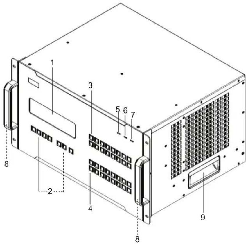
text_image
Technical diagram of a server rack with numbered components for identification| No. | Component Description |
| 1 LCD | Display The LCD Display shows the options for configuring and operating the VM1600A. See Front Panel Pushbuttons, page 41, for details. |
| 2 Function Pushbuttons | Use the UP, DOWN and CANCEL buttons to navigate the LCD display to configure the installation. Press the Video, Audio, Menu and Profile buttons to use each function. See Front Panel Pushbuttons, page 41, for details.Note: The pushbuttons have LEDs that light to indicate they have been selected. |
| 3 Input Pushbuttons (1-16) | These pushbuttons refer to the Input ports on the VM1600A rear panel. Press to select the Input port. These pushbuttons may also correspond to menu options, profiles and other selections. |
| 4 Output Pushbuttons (1-16) | These pushbuttons refer to the Output ports on the VM1600A rear panel. Press to select the Output port. |
| 5 Alarm LED The Alarm | m LED lights red to indicate the power or fan module has failed. |
| No. | Component Description | |
| 6 | RedundantPower LED | This LED lights green to indicate the redundant power module is plugged in and working. |
| 7 | Primary PowerLED | This LED lights green to indicate the primary power module is plugged in and working. |
| 8 | Handles The two front handles are used to install the unit into a rack. | |
| 9 | RecessedHandles | The two side handles are used to transport the unit. |
VM1600A Rear View
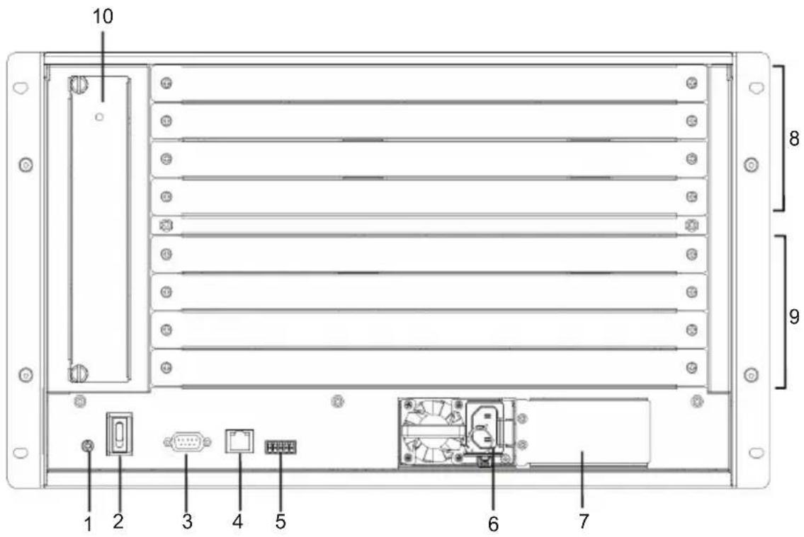
text_image
10 8 9 1 2 3 4 5 6 7| No. | Component Description | |
| 1 | Grounding Terminal | The grounding wire attaches here. See Grounding, page 35, for further details. |
| 2 | Power Switch This is a standard rocker switch that powers the unit on and off. | |
| 3 | RS-232 Serial Port Connect a computer or high-end system controller via this serial port. | |
| 4 | Ethernet Port In order to access the VM1600A's web Graphical User Interface (GUI), the VM1600A must be connected to the network. The cable that connects the VM1600A to your LAN plugs in here. See Cable Connection, page 38, for further details | |
| 5 | RS-485 / RS-422 Serial Port | Connect a computer or high-end system controller via this serial port. |
| 6 | Primary Power Supply | This is a standard 3-pin power socket. The power cord from a source plugs in here. |
| 7 | Redundant Power Slot (Optional) | This slot with protective cover is used to install an additional power supply for redundant power protection.Note: The extra power module is not included in the VM1600A package. See Optional Equipment, page 19, for details. |
| 8 | Input Board Slots Unscrew | the cover to insert the Input boards into these 4 horizontal slots. The source devices connect to the inserted Input boards. |
| 9 | Output Board slots Unscrew | the cover to insert the output boards into these 4 horizontal slots. The display devices connect to the inserted Output boards. |
| 10 | Fan Module This slot contains the fan module. The fan is hot-pluggable and the panel unscrews to install a replacement module. For more information, see Optional Equipment, page 19. | |
VM7584 Front View
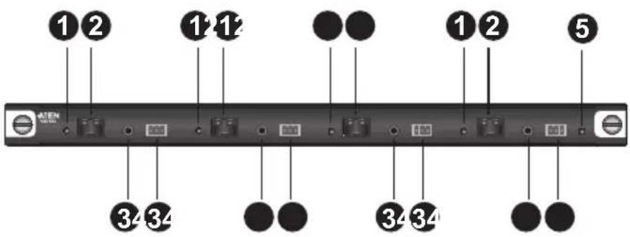
text_image
1 2 1 1 1 2 5 ATEN 34 34 34 34| No. | Component Description |
| 1 Link LEDs Light up to | indicate stable connection with the connected source devices. |
| 2 SFP+ Ports Connect | up to four VE883T units via SFP+ modules to receive data from input devices. |
| 3 IR Ports Connect to the supplied IR Receiver or IR Emitter to bypass IR signals via the VM7584. To operate from the VM7584's side, plug in the IR Receiver to the VM7584, and the IR Emitter to the output board that you wish to bypass the IR signals. | |
| 4 RS-232 Channel Ports | Connect to a serial controller to bypass RS-232 serial signals. |
| 5 Status LED Indicates | the working status of the unit. |
VM8584 Front View
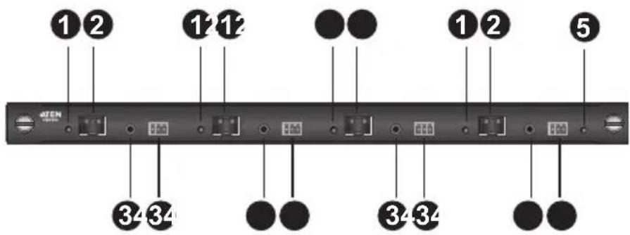
text_image
1 2 1 1 2 1 2 5 34 34 34 34| No. | Component Description | |
| 1 | Link LEDs Light up to | indicate stable connection with the connected source devices. |
| 2 | SFP+ Ports Connect | up to four VE883R units via SFP+ modules to transmit data to output devices. |
| 3 | IR Ports Connect to the | supplied IR Receiver or IR Emitter to bypass IR signals via the VM8584. To operate from the VM8584's side, plug in the IR Receiver to the VM8584, and the IR Emitter to the input board that you wish to bypass the IR signals. |
| 4 | RS-232 Channel Ports | Connect to a serial controller to bypass RS-232 serial signals. |
| 5 | Status LED Indicates | the working status of the unit. |
VM7514 Front View
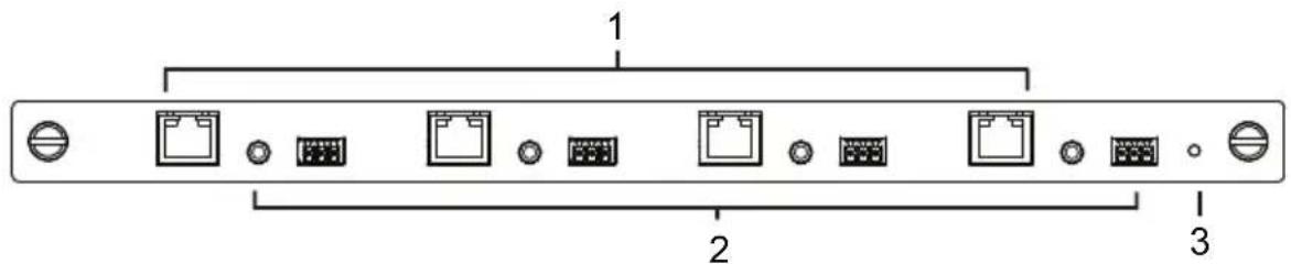
text_image
1 2 3| No. | Component Description | |
| 1 | HDBaseT Input Ports Connect the Cat 5e cables from your HDBaseT transmitter to these ports. | |
| 2 | IR / RS-232Input Ports | Connect the cables from your IR transmitter to the mini stereo jack ports, and connect the cables from your RS-232 device to the RS-232 ports. |
| 3 | Status LED The VM7514 has an LED to indicate the working status. | |
VM8514 Front View
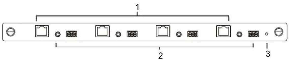
text_image
1 2 3| No. | Component Description | |
| 1 | HDBaseT OutputPorts | Connect the Cat 5e cables from your HDBaseT receiver to these ports. |
| 2 | IR/RS-232Output Ports | Connect the cables from your IR receiver to the mini stereo jack ports, and connect the cables from your RS-232 device to the RS-232 ports. |
| 3 | Status LED The VM8514 has an LED to indicate the working status. | |
VM7904 Front View
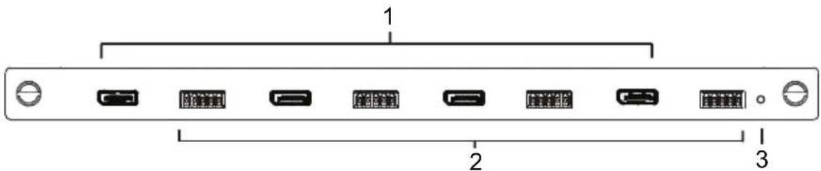
text_image
1 2 3| No. | Component Description | |
| 1 | DisplayPort Input Ports | Connect the cables from your DisplayPort video source devices to these ports. |
| 2 | Audio Input Ports Connect | the cables from your audio source devices to these ports. |
| 3 | Status LED Indicates the working status of the unit. | |
VM7824 Front View
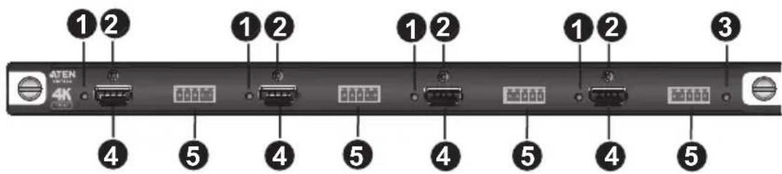
text_image
1 2 1 2 1 2 1 2 3 ATEN 4K 4 5 4 5 4 5 4 5 4 5| No. | Component Description | |
| 1 | Link LEDs Lights up to indicate stable connection with the connected source devices. | |
| 2 | ATEN LockPro ^TM Screws | Optionally secure an ATEN LockPro ^TM to hold a the HDMI cable in place and prevent it from falling off. |
| 3 | Status LED Indicates the working status of the unit. | |
| 4 | HDMI Input Ports Connect | to HDMI source devices via HDMI cables. |
| 5 | Audio Input Ports Connect | to audio source devices that you wish to embed via audio cables. |
VM8824 Front View

text_image
1 2 ATEN 4K [300] 1 2 1 2 1 2 3 4 5 4 5 4 5 4 5| No. | Component Description | |
| 1 | Link LEDs Lights up to indicate stable connection with the connected display devices. | |
| 2 | ATEN LockProTM Screws | Optionally secure an ATEN LockProTM to hold a the HDMI cable in place and prevent it from falling off. |
| 3 | Status LED Indicates the working status of the unit. | |
| 4 | HDMI Output Ports Connect to HDMI-enabled displays via HDMI cables. | |
| 5 | Audio Output Ports Connect to speakers or audio output devices that you via audio cables. |
VM7814 / VM7804 Front View
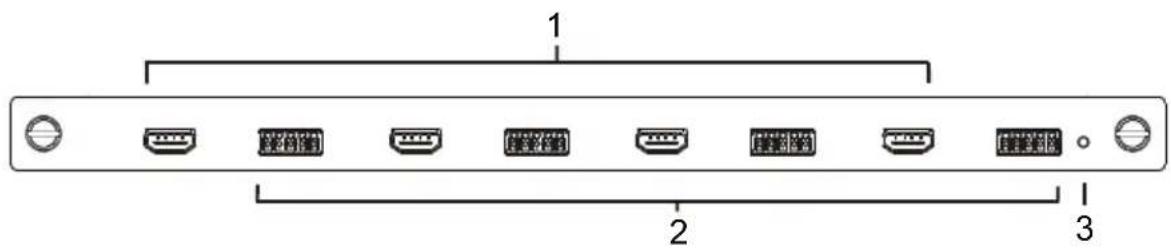
text_image
1 2 3| No. | Component Description | |
| 1 | HDMI Input Ports Connect | the cables from your HDMI video source devices to these ports. |
| 2 | Audio Input Ports Connect | the cables from your audio source devices to these ports. |
| 3 | Status LED The VM7814 / | VM7804 has an LED to indicate the working status. |
VM8814 / VM8804 Front View
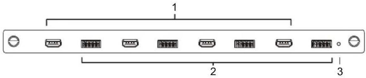
text_image
1 2 3| No. | Component Description | |
| 1 | HDMI Output Ports Connect | ct the cables from your HDMI display devices (monitors, projectors, TVs) to these ports. |
| 2 | Audio Output Ports Connect | ct the cables from your output audio devices or speakers to these ports. |
| 3 | Status LED The VM8814 / | VM8804 has an LED to indicate the working status. |
VM7604 Front View
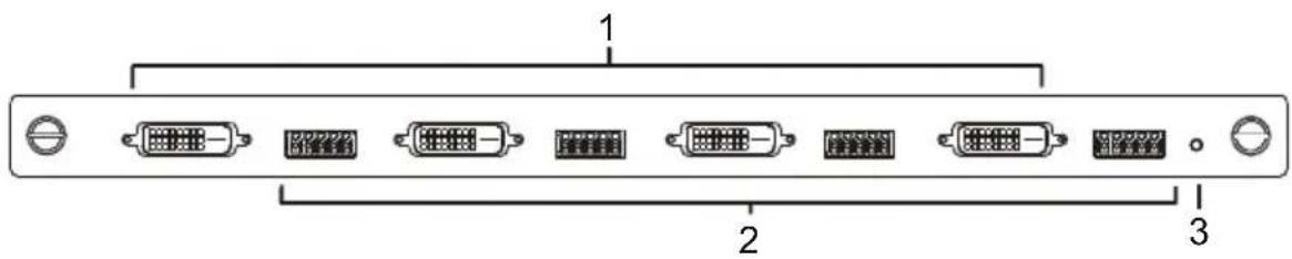
text_image
1 2 3| No. | Component Description | |
| 1 | DVI Input Ports Connect the cables from your video source devices to these ports. | |
| 2 | Audio Input Ports Connect the cables from your audio source devices to these ports. | |
| 3 | Status LED The VM7604 has an LED to indicate the working status. |
VM8604 Front View

text_image
1 2 3| No. | Component Description | |
| 1 | DVI Output Ports Connect | the cables from display devices (monitors, projectors, TVs) to these ports. |
| 2 | Audio Output Ports Connect | the cables from your output audio devices or speakers to these ports. |
| 3 | Status LED The VM8604 has an LED to indicate the working status. | |
VM7104 Front View

text_image
1 2 3| No. | Component Description | |
| 1 VGA Input Ports Connect the cables from your VGA video source devices to these ports. | ||
| 2 Audio Input Ports Connect the cables from your audio source devices to these ports. | ||
| 3 Status LED The VM7104 has an LED to indicate the working status. | ||
VM7404 Front View

text_image
1 2 3| No. | Component Description | |
| 1 | SDI Input Ports Connect the cables from your video source devices to these ports. | |
| 2 | Analog Stereo Audio Input Ports | Connect the cables from your audio source devices to these ports. |
| 3 | Status LED The VM7404 has an LED to indicate the working status. | |
VE805R / VE816R Front View
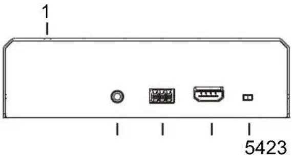
text_image
1 5423VE805R / VE816R Rear View
natural_image
Front view of a device rear panel showing two ports with labels 6 and 7 (no text or symbols on the components)| No. | Component Description | |
| 1 | LEDs Three LEDs – Power, Link and HDMI Out – light when the unit is properly connected to an appropriate source.◆ Power - lights Green to indicate the unit is receiving power.◆ Link - lights Orange to indicate that communication between VE805R / VE816R and output board is established.◆ HDMI Out - lights Orange to indicate the HDMI output signal is good. LED blinks Orange every second to indicate that the device is in F/W upgrade mode. | |
| 2 | IRPort Connect the IR transmitter or receiver cable port into this mini stereo jack port. | |
| 3 | RS-232 Port Use the captive screw connectors (3 pole) to connect the cable from your serial device into the RS-232 port. | |
| 4 | HDMI Output Port Connect the cable from your HDMI display device (monitors, projectors, TVs) into this port. | |
| 5 | Firmware Upgrade Switch | Set this switch to OFF (left) for normal operation. Set this switch to ON (right) and reset the unit's power to enter firmware upgrade mode. For details, see System Setup, page 122. |
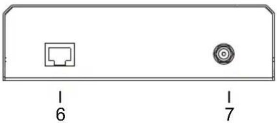
| 6 | HDBaseT Input Use a Cat 5e cable to connect the VE805R / VE816R to the VM8514 output board. | |
| 7 | Power Jack The power adapter cable plugs connects here. |
Chapter 2
Hardware Setup

-
Important safety information regarding the placement of this device is provided on page 163. Please review it before proceeding.
-
Make sure that the power to all devices connected to the installation are turned off. You must unplug the power cords of any computers that have the Keyboard Power On function.
Rack Mounting
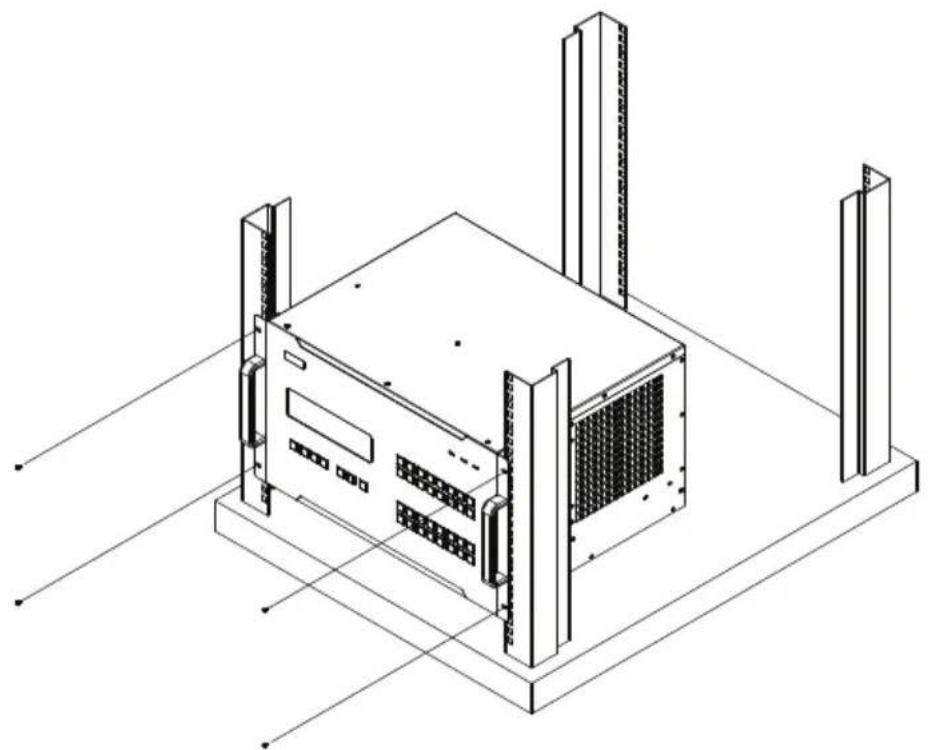
The Modular Matrix Swtich can be mounted in a 19" (1U) system rack. For the most convenient front panel operation at the local site, mount the unit at the front of the rack, as follows:
-
Position the unit in the front of the rack, and align the holes of the unit's built-in mounting brackets with the holes in the rack.
-
Use screws to attach the unit to the rack.
natural_image
Isometric line drawing of a server rack unit with mounting brackets and ventilation grilles (no text or symbols)Mounting with Brackets
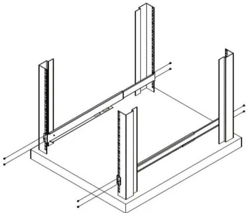
You can also use mounting brackets to install the VM1600A, as shown below.
Note: The Mounting Kit is not included with the package. To purchase a mounting kit please contact your dealer.
- Screw the mounting brackets (Easy Installation Rack Mount Kit, see page 19) to the rack, as shown in the diagram.
natural_image
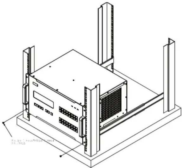
Isometric line drawing of a structural frame with vertical supports and diagonal braces (no text or symbols)- Slide the unit along the brackets, then screw the front panel to the rack.
natural_image
Isometric technical line drawing of a server rack unit with mounting brackets and ventilation grilles (no text or symbols)Grounding
To prevent damage to your installation, it is important that all devices are properly grounded.
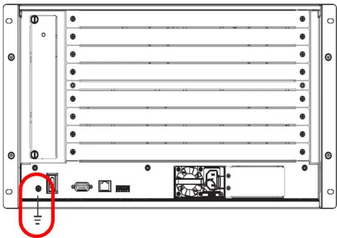
- Use a grounding wire to ground the installation using the VM1600A's rear panel, by connecting one end of the wire to the grounding terminal, and the other end of the wire to a suitable grounded object.
natural_image
Back panel of a server rack with ventilation unit, ports, and connectors (no text or symbols visible)- Make sure that all devices in your installation are properly grounded.
Note: The grounding wire is not included in the package. Please contact your dealer for details of purchase.
Input / Output Board Installation
To install the I/O boards in the VM1600A, do the following:
Note: The four top slots on the Modular Matrix Switch are for the Input boards. The four bottom slots on the Modular Matrix Switch are for the Output boards.
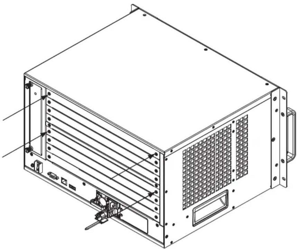
- On the rear of the VM1600A, unscrew the two screws from a top and bottom slot, and remove the covers.
natural_image
Technical line drawing of a server rack unit with ventilation grilles and mounting hardware (no text or symbols)(Continues on next page.)
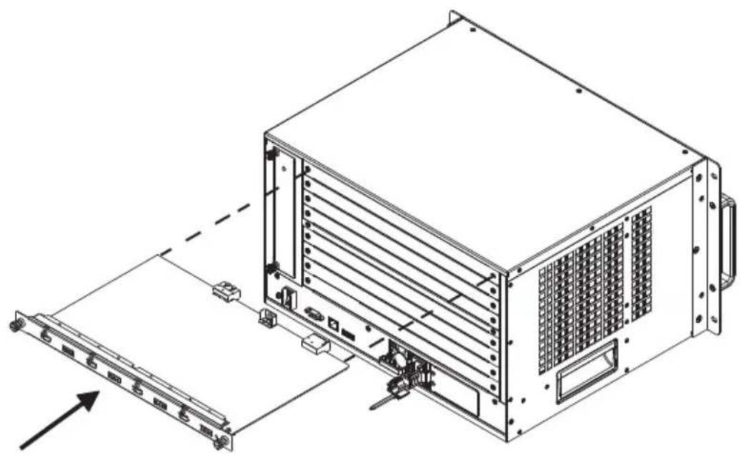
- Slide an input board into a top slot and tighten the screws to secure the board to the VM1600A.
natural_image
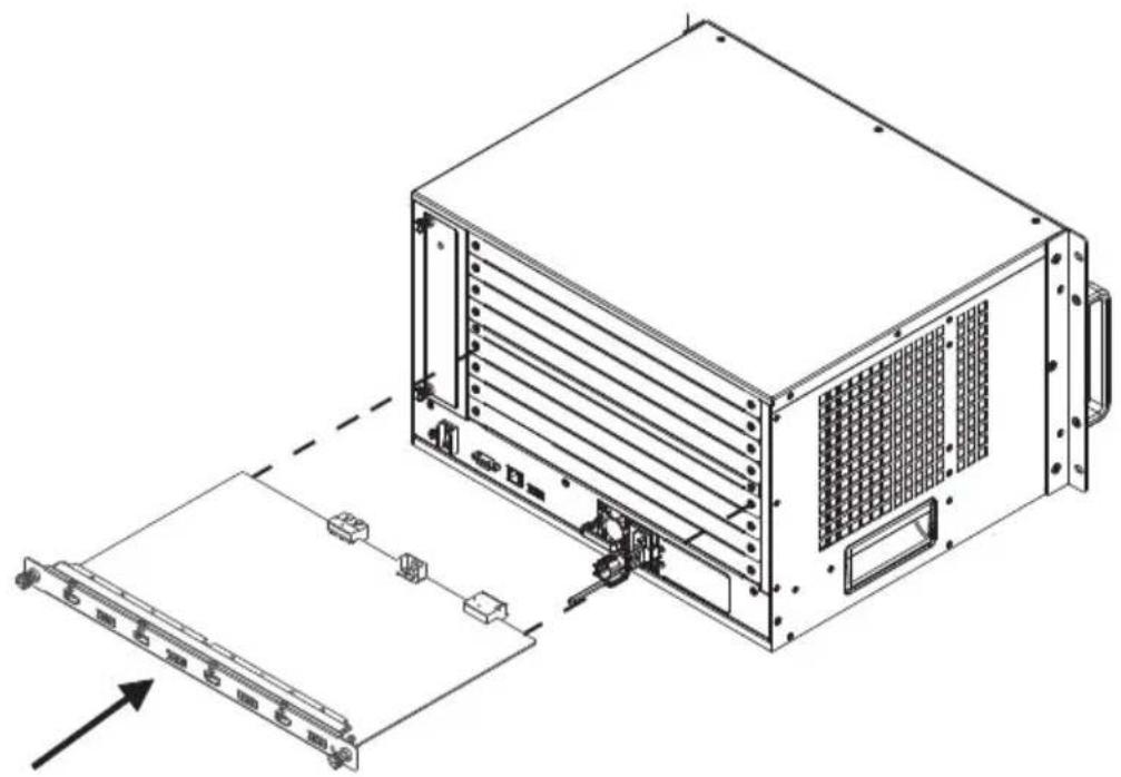
Technical line drawing of a server rack unit with mounting bracket and drive panel (no text or symbols)- Slide an output board into a bottom slot and tighten the screws to secure the board to the VM1600A.
natural_image
Technical line drawing of a server rack unit with attached panel and connector components (no text or symbols)-
Repeat steps 2 and 3 to install additional I/O boards.
-
Power on the VM1600A.
Cable Connection
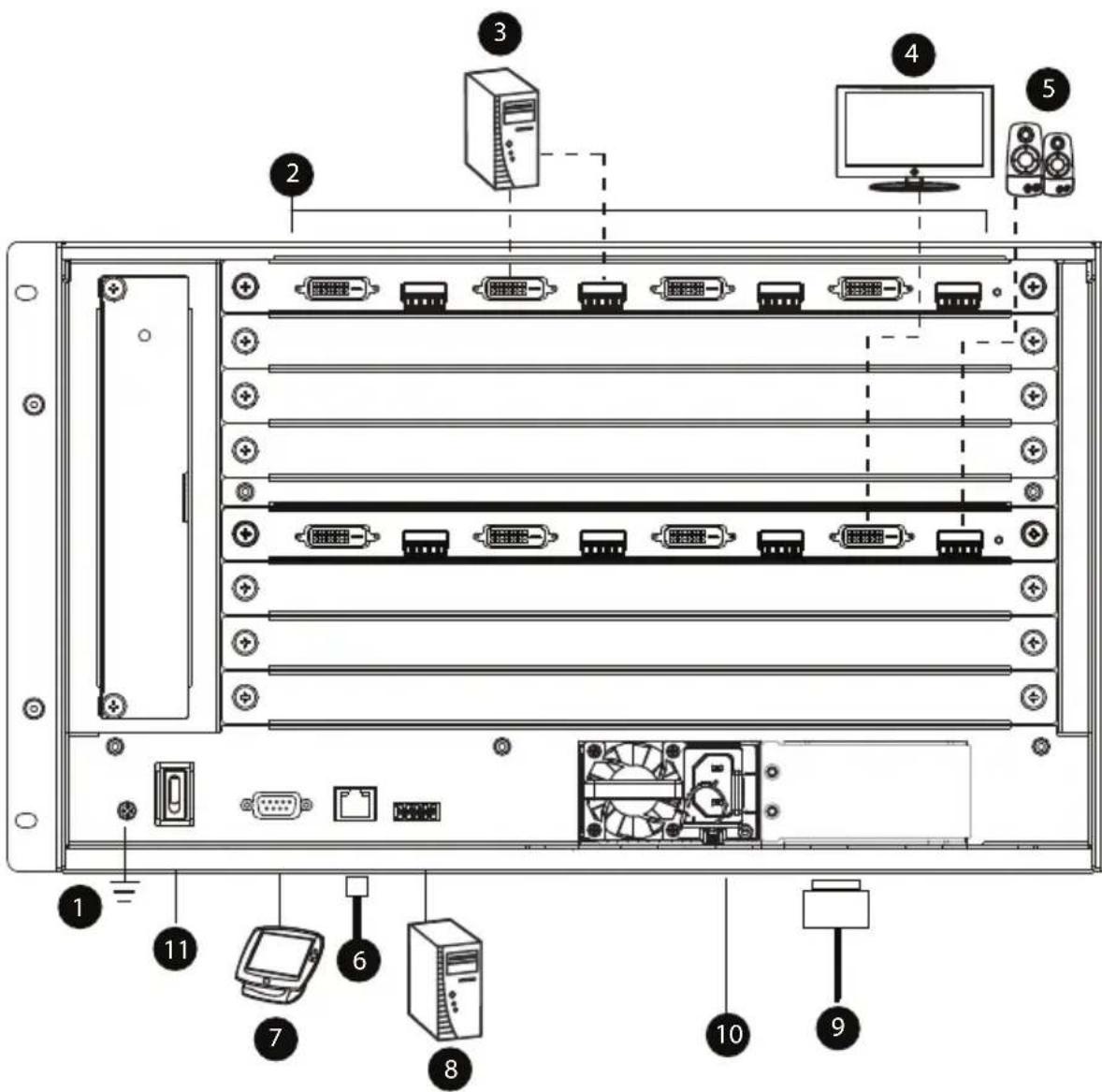
Installation of the VM1600A is simply a matter of connecting the appropriate cables. Refer to the installation diagram on the following page (the numbers in the diagram correspond to the steps below), and do the following:
- Use a grounding wire to ground the unit by connecting one end of the wire to the grounding terminal, and the other end of the wire to a suitable grounded object.
Note: Do not omit this step. Proper grounding helps to prevent damage to the unit from surges or static electricity.
- Unscrew the covers on the VM1600A rear panel and insert the I/O boards into the horizontal slots (See Input / Output Board Installation, page 36, for details).
- Connect your AV source device(s) to the Video and Audio port(s) of the Input Board on the VM1600A.
- Connect your video display device(s) to the Video port(s) of the Output Board on the VM1600A.
- Connect your speakers / audio output device(s) to the Audio port(s) of the Output Board on the VM1600A.
- (Optional) To access the web GUI or the Video Matrix Control app, plug a Cat 5e cable from the network into the VM1600A's Ethernet port.
- (Optional) If you are using a serial control function, use an appropriate serial cable to connect the computer or serial controller to the VM1600A's female RS-232 serial port.
- (Optional) If you are using the serial control function to control multiple VM1600A's, use an appropriate serial cable to connect the computer or serial controller to the VM1600A's female RS-485 / RS-422 captive screw connector. The VM1600A package includes a terminal block connector that can be used for this connection.
-
Plug the power cord supplied with the package into the VM1600A's 3-prong socket, and then into a power source.
-
(Optional) Plug in an additional power module for redundancy if required.
Note: Secondary power modules are not included in the VM1600A package. See Optional Equipment, page 19, for details.
- Power on the VM1600A and all devices in the installation.
Installation Diagram
text_image
Diagram of a server rack with labeled components including drive, ports, and computer monitorThis Page Intentionally Left Blank
Overview
The Modular Matrix Switch installation can be configured and operated locally via the VM1600A front panel LCD and pushbuttons.
Front Panel Pushbuttons
The VM1600A front panel has easy-to-use pushbuttons for selecting which video/audio source shows on which display.
Basic Navigation
The VM1600A's front panel LCD display operation is easy and convenient. Please note the following front panel button operations:
- Press the VIDEO pushbutton to configure the video connections.
- Press the AUDIO pushbutton to configure the audio connections.
◆ Use the MENU pushbutton to: - Access the Menu page options: IP Setting, Serial Port Setting, Operation Mode, Security Mode, and Save to a Profile.
- Awake the VM1600A from standby mode.
- Use the PROFILE pushbutton to select a profile or switch between the connection profiles which have been added to the Profile List (see page 69). Pressing this pushbutton for longer than 3 seconds displays the Save to a Profile page (see page 64).
- Use the CANCEL (☐) pushbutton to go back a level, return to the Main screen, stop or exit an operation.
- Use the UP (A) and DOWN (V) pushbuttons to go to the next or previous options.
- Use the Input / Output (1–16) pushbuttons to select the Input/Output port. The pushbuttons may also correspond to menu options, profiles, and so on.
Front Panel LCD
The VM1600A features an LCD display for convenient configuration. This allows you to perform operations such as viewing the IP settings, configuring the serial port, setting EDID/CEC/OSD/Output Status, selecting security settings, and loading/saving connection profiles.
LCD Password
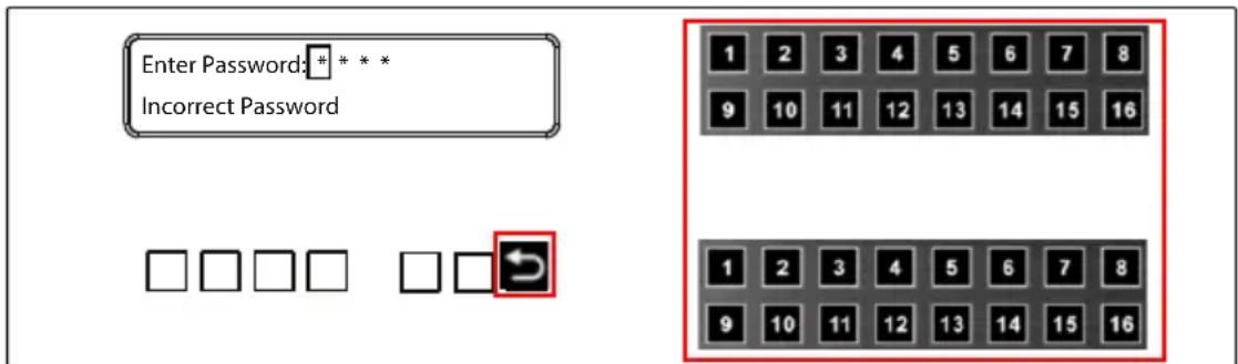
If the VM1600A has been configured to require a password for local operation (see Security Mode, page 61), the password screen appears when the VM1600A is powered on, and the cursor flashes on the first digit. Enter a 4-digit password to continue to the Main Screen.
Note: If you are accessing the VM1600A for the first time, the default password is 1234.
text_image
Enter Password: * * * Incorrect Password 1 2 3 4 5 6 7 8 9 10 11 12 13 14 15 16 1 2 3 4 5 6 7 8 9 10 11 12 13 14 15 16To enter a password, do the following:
- Check that the cursor is flashing on the first digit.
- Use the front panel number pushbuttons (1-9) to enter a 4-digit password. After the fourth digit, the cursor goes back to the first digit.
- Press Cancel to clear the password. The digits revert to 4 asterisks (*) and the cursor returns to the first digit.
Note: 1. The VM1600A password can be any four digit combination between 1111 to 9999.
- If you enter an incorrect password, the cursor goes back to the first digit and reverts to flashing. The Incorrect Password message displays at the bottom of the screen, but clears as soon as a new digit is entered.
- If Password (see Security Mode, page 61) is Enabled, the LCD display time-out is 5 minutes by default.
Port Switching
From the Main Screen, you can configure the Input-to-Output port connections to associate an Input source device to an Output display.
Video / Audio Pushbutton
Before switching port connections, use the Video or Audio pushbuttons to select whether to switch only the video or the audio signal exclusively. Otherwise, both video and audio channels are configured together (default).
text_image
INPUT 1 2 5 5* 1 1 3 4 OUTPUT 1 2 3 4 5 6 7 8 INPUT 1 2 5 5 1 1 3 4 V+A OUTPUT 9 10 11 12 13 14 15 16 P1
natural_image
Grid of empty squares arranged in two rows and three columns (no text or symbols)
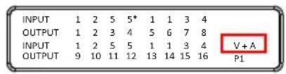
- Press the Video* pushbutton to configure Video connections. The built-in LED lights up and the LCD displays Video on the lower right side. Press the button again to cancel.
- Press the Audio* pushbutton to configure Audio connections. The built-in LED lights up and the LCD displays Audio on the lower right side. Press the button again to cancel.
- If both Video and Audio built-in LEDs are turned off, the video and audio channels are configured together and the LCD displays V + A.
Note: Press the Video or Audio pushbutton to independently switch either signal to a different source.
Input Port Selection
Use the Input Port pushbuttons to select the Input port you want to configure.
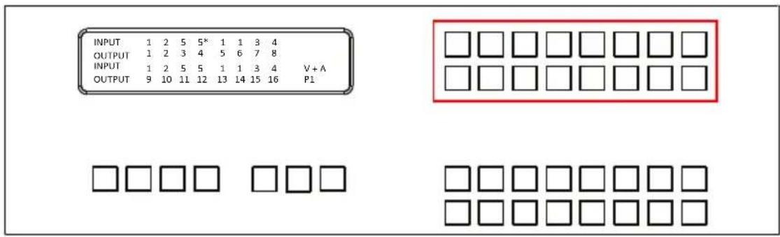
text_image
INPUT 1 2 5 5* 1 1 3 4 OUTPUT 1 2 3 4 5 6 7 8 INPUT 1 2 5 5 1 1 3 4 V+A OUTPUT 9 10 11 12 13 14 15 16 P1To select which input source displays on each output port, do the following:
- Press an Input port pushbutton. The Output port LED(s) tied to the said Input port light up. In the example below, pressing Input port 1 shows it is tied to Output ports 1 and 2.
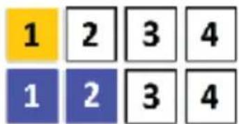
text_image
1 2 3 4 1 2 3 4- To disconnect an Output port from an Input port, press the corresponding Output port pushbutton.
In the example below, Output port 2 has been disconnected from Input port 1.
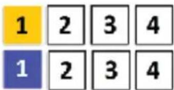
text_image
1 2 3 4 1 2 3 4- To switch to another Input port, press any Input port pushbutton. The Output port LED(s) tied to the said Input port light up.
In the example below, pressing Input port 2 shows it is tied to Output ports 3 and 4.
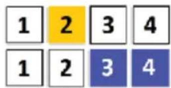
text_image
1 2 3 4 1 2 3 4- To connect Output port 2 to Input port 2 in the example above, press the Output port 2 pushbutton. The Output port 2 LED will also light up. This indicates that Input port 2 is now connected to Output ports 2, 3 and 4.
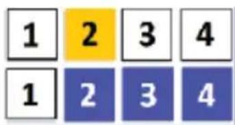
text_image
1 2 3 4 1 2 3 4Once the signal from the selected Input port is successfully tied to the Output port, the LEDs turn off and the LCD information is updated.
Note: 1. Pressing an Input port a second time deselects it.
-
Input ports that are not configured or tied to any output port do not appear in the LCD screen.
-
Pressing the Cancel pushbutton once stops the Input Port Selection operation and the LCD displays the active setting. Pressing the Cancel pushbutton again turns all LEDs off.
-
After 10 seconds of inactivity, all the LEDs turn off.
Output Port Selection
Use the Output Port pushbuttons to select the Output port you want to configure.
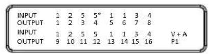
text_image
INPUT 1 2 5 5* 1 1 3 4 OUTPUT 1 2 3 4 5 6 7 8 INPUT 1 2 5 5 1 1 3 4 V + A OUTPUT 9 10 11 12 13 14 15 16 P1
natural_image
Grid of 16 empty square boxes arranged in two rows and three columns (no text or symbols)
text_image
Grid of empty squares in a 5x5 pattern, each cell is blackTo select which output display corresponds to each input source, do the following:
- Press any Output port pushbutton (1-16). The selected Output port LED lights steady.
In the example below, Output port 1 pushbutton has been pressed. Available Input ports light up. Because no Input LEDs are on, no ports have already been assigned to Output port 1.
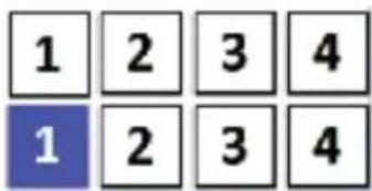
text_image
1 2 3 4 1 2 3 4-
If an Output port pushbutton is pressed a second time, it is deselected and the LED turns off.
-
To connect the selected Output port(s) to an Input port, press the Input port pushbutton to which you want the Output port(s) tied. The newly selected Input port LED light up, and the LCD information is updated.
In the example below, pressing Input port 2 ties it to Output ports 2, 3 and 4.
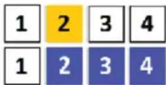
text_image
1 2 3 4 1 2 3 4- To switch Output ports 2, 3 and 4 to another Input port (and disconnect it from Input port 2), press another Input port pushbutton to which you want them tied.
In the example below, Input port 3 has been pressed and is now connected to Output ports 2, 3 and 4.

text_image
1 2 3 4 1 2 3 4Note:
- To cancel an output selection, press the pushbutton again.
- Pressing the Cancel pushbutton once stops the Output Port Selection operation, and the LCD displays the active setting. Pressing the Cancel pushbutton again turns all LEDs off.
◆ After 10 seconds of inactivity, all the LEDs turn off.
Profile Pushbutton
From the Main screen; pressing the PROFILE pushbutton switches between the connection profiles added to the Profile Selection list (see Setting the Standby Mode, page 69). If a connection profile is in use, it is shown from the Main screen on the lower right corner of the LCD display.
| INPUT | 1 | 2 | 5 | 5* | 1 | 1 | 3 | 4 | |
| OUTPUT | 1 | 2 | 3 | 4 | 5 | 6 | 7 | 8 | |
| INPUT | 1 | 2 | 5 | 5 | 1 | 1 | 3 | 4 | V + A |
| OUTPUT | 9 | 10 | 11 | 12 | 13 | 14 | 15 | 16 | P1 |





◆ Use the front panel number pushbuttons to select a profile:
- Input ports 1–16 correspond to Profile P1 to P16
- Output ports 1–16 correspond to Profile P17 to P32
Note: If a Profile is available for selection, its corresponding Input/Output port LED lights.
The selected pushbutton lights steady, and the VM1600A immediately applies the port connections configured in the Profile. The selected Profile is shown as P1-P32 in the LCD's lower right corner.
- Up and Down buttons correspond to the previous or next profile in the Profile List, which can be edited via the GUI.
If there are no profiles configured, an error message “No Profile List defined. Profile List can be edited via the Web GUI.” is displayed.
- The Profile List and connections can be edited from the Profile List page of the Browser GUI. See Setting the Standby Mode, page 69.
- Press the Cancel pushbutton to turn off the Profile LED.
- Pressing the Profile pushbutton for longer than 3 seconds displays the Save to a Profile page (see Save to a Profile, page 64).
Note: To save a configuration to a profile using the Front Panel pushbuttons, follow the steps in Save to a Profile, page 64.
LCD Menu
Use the Menu pushbutton to switch between the Main Screen and Menu page. From the Main Screen press the Menu pushbutton to access the Menu page; use the pushbuttons (1-16) to cycle through the menu options, starting from IP Setting, in the order show in the table below:
| Menu Page Sub-Menu Page(s) | |||
| IP Setting IP Address | |||
| Subnet Mask | |||
| Gateway | |||
| Serial Port Setting Baud Rate 9600 / 19200 / 38400 / 1 | 15200 | ||
| Operation Mode | EDID | Default / Port1 / Remix / Customized | |
| CEC On / NA | |||
| OSD On / NA | |||
| Output Status Video On / NA | NA | ||
| Stereo Audio 01-16 | |||
| Output Resolution | 01-16 | ||
| Security Mode Mode | None | ||
| Password Enable | |||
| Lock Screen | |||
| Change Password | Old Password | New Password | |
| Save to a Profile | Save to a Profile No. | 01-32 | |
| Play/Stop the Profile Schedule | |||
| Turn Video Wall Off | |||
Note: 1. The highlighted values are the default settings of the VM1600A.
- Upon VM1600A startup, check the front panel LCD to view the loading progress. If the LCD Menu fails to load, an error message displays. Reset the unit and try again.
LCD Main Screen
The Main Screen shows the Input–Output port pairs, with the Output ports shown in sequential order (1–16) at the bottom half.
| INPUT | 1 | 2 | 5 | 5* | 1 | 1 | 3 | 4 | |
| OUTPUT | 1 | 2 | 3 | 4 | 5 | 6 | 7 | 8 | |
| INPUT | 1 | 2 | 5 | 5 | 1 | 1 | 3 | 4 | V + A |
| OUTPUT | 9 | 10 | 11 | 12 | 13 | 14 | 15 | 16 | P1 |
- The front panel pushbutton label (1–16) corresponds to the Input ports and Output ports on the unit’s rear panel.
- Use the Menu pushbutton to go to the Menu page.
- Use the Profile pushbutton to switch between profile connections (see Setting the Standby Mode, page 69).
IP Setting
To view the VM1600A's IP settings, press the Menu pushbutton (lights). This takes you to the Menu page, shown below:
1: IP Setting
2: Serial Port Setting
3: Operation Mode
4: Security Mode

-
From the Menu page:
-
Press 1 to go to the IP Setting page.
- Press 2 to go to the Serial Port Setting page.
- Press 3 to go to the Operation Mode page.
- Press 4 to go to the Security Mode page.
- Press Down button to go to the next page.
- Press Menu to return to the Menu Screen.
-
Press Cancel to return to the Main Screen.
-
After pressing 1, the IP address, Subnet Mask and Gateway information are shown:
IP Address: 192.168.0.60
Subnet Mask: 255.255.255.0
Gateway: 192.168.0.1
◆ The default IP address is 192.168.0.60.
◆ The default Subnet Mask is 255.255.255.0.
◆ The default Gateway is 192.168.0.1.
- Press Cancel to return to the previous step without change.
Serial Port Setting
To configure the VM1600A's serial port settings, select Serial Port Setting from the Menu page.

text_image
1: IP Setting 2: Serial Port Setting 3: Operation Mode 4: Security ModeSerial Port Address Setting
To set the VM1600A's serial port address, do the following:
- Select Serial Port Address Setting from the Serial Port Setting submenu by pressing 1:
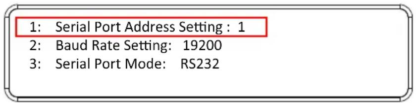
text_image
1: Serial Port Address Setting : 1 2: Baud Rate Setting: 19200 3: Serial Port Mode: RS232- Press pushbuttons 1–16 to make your selection.
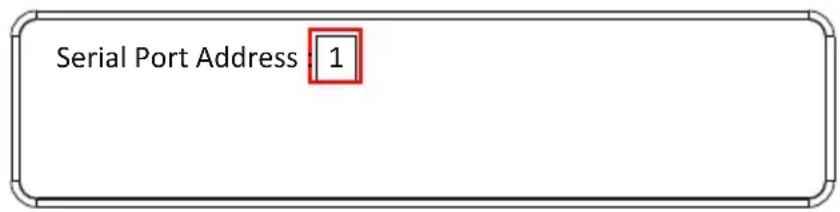
text_image
Serial Port Address : 1Note: The default serial port address is 1. This address is used for RS422/485 commands to control multiple VM1600A's.
- Press Menu to return to the Menu page.
- Press Cancel to return to the previous step without saving.
Baud Rate
- Select Baud Rate Setting from the Serial Port Setting submenu by pressing 2:
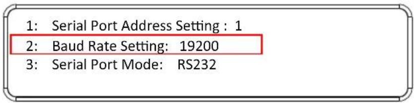
text_image
1: Serial Port Address Setting : 1 2: Baud Rate Setting: 19200 3: Serial Port Mode: RS232- Press pushbuttons 1–4 to make your selection.
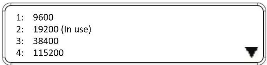
text_image
1: 9600 2: 19200 (In use) 3: 38400 4: 115200Baud Rate options are:
◆ 1:9600
◆ 2:19200
◆ 3:38400
◆ 4:115200
Note: The default baud rate is 19200.
- Press Menu to return to the Menu page.
- Press Cancel to return to the previous step without saving.
Serial Port Mode
- Select Serial Port Mode from the Serial Port Setting submenu by pressing 3:
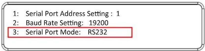
text_image
1: Serial Port Address Setting : 1 2: Baud Rate Setting: 19200 3: Serial Port Mode: RS232- Press pushbuttons 1–2 to make your selection.
1: RS232 (In use)
2: RS422/RS485
Serial Port options are:
1: RS-232
◆ 2: RS-422 / RS-485
Note: The default serial port mode is RS-232.
- Press Menu to return to the Menu page.
- Press Cancel to return to the previous step without saving.
Operation Mode
The EDID, CEC, OSD and Output Status features are adjusted from the Operation Mode menu.
1: EDID Mode: Default
2: CEC
3: OSD
4: Output Status

- EDID (extended display identification data) is used to apply a preset video configuration (EDID Mode), which utilizes the best resolution across different monitors.
- Consumer Electronics Control (CEC) allows interconnected HDMI devices to communicate and respond to one remote control.
- The OSD, when enabled for a port, displays real-time port switching information on the screen.
- The Output Status shows whether the video/audio of an Output port is turned on or off.
EDID
To adjust the EDID mode, do the following:
- From the Operation page, press pushbutton 1 to access the EDID Mode page:
1: EDID Mode: Default
2: CEC
3: OSD
4: Output Status

- Press pushbuttons 1-4 to make your selection.
1: Port 1
2: Default (In use)
3: Remix
4: Customized

EDID Mode options are:
| EDID Option Description | |
| 1: Default ATEN's default EDID data is passed to all video sources by default when the system is powered on. | |
| 2: Port1 EDID data read from port 1 is passed to all video sources.The system will enforce the Default EDID setting if port 1 is not occupied. | |
| 3: Remix This mode reads the EDID data from all connected displays and generates the optimum EDID for all video sources. The system will not re-generate a new EDID when a new device is plugged in, unless triggered by a pushbutton or command. | |
| 4: Customized This mode features an EDID Wizard that allows user-defined EDID configurations for optimum output.See Customized Mode, page 108. |
-
Press Menu to return to the Menu page.
-
Press Cancel to return to the previous step without change.
Note: The default EDID setting is Default.
CEC
To configure the CEC settings, do the following:
- From the Operation page, press pushbutton 2 to access the CEC page:
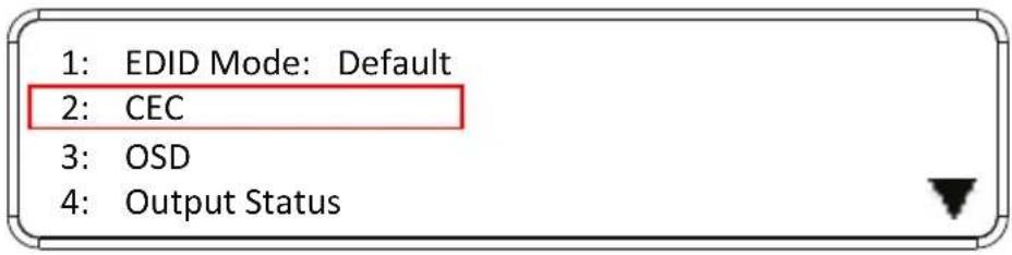
text_image
1: EDID Mode: Default 2: CEC 3: OSD 4: Output Status- Press pushbuttons 1–16 to enable (ON) or disable (NA) the CEC feature for the output port. If the port does not support CEC, an NA is shown.
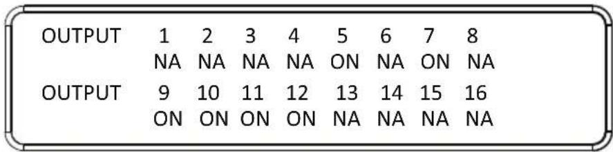
text_image
OUTPUT 1 2 3 4 5 6 7 8 NA NA NA NA ON NA ON NA OUTPUT 9 10 11 12 13 14 15 16 ON ON ON ON NA NA NA NANote: The default CEC setting is Off.
-
Press Menu to return to the Menu page.
-
Press Cancel to return to the previous step without saving.
OSD
The On-Screen Display or OSD feature enables real-time text updates to appear on the display device's screen for any configuration changes made to the Output port via the VM1600A's front panel, remote control or Web GUI.
To configure the OSD setting for each output port, do the following:
- From the Operation page, press pushbutton 3 to access the OSD page:
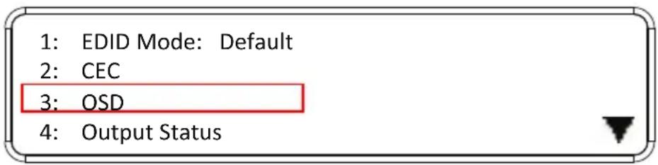
text_image
1: EDID Mode: Default 2: CEC 3: OSD 4: Output Status- Press pushbuttons 1–16 to enable (ON) or disable (NA) the OSD feature for the port.
| OUTPUT | 1 | 2 | 3 | 4 | 5 | 6 | 7 | 8 |
| NA | NA | NA | NA | ON | NA | ON | NA | |
| OUTPUT | 9 | 10 | 11 | 12 | 13 | 14 | 15 | 16 |
| ON | ON | ON | ON | NA | NA | NA | NA |
Note: The default OSD setting is Off.
- Press Menu to return to the Menu page.
- Press Cancel to return to the previous step without saving.
Output Status
To configure the Output Status settings for each output port, do the following:
- From the Operation Mode screen, press pushbutton 4 to access the Output Status page:
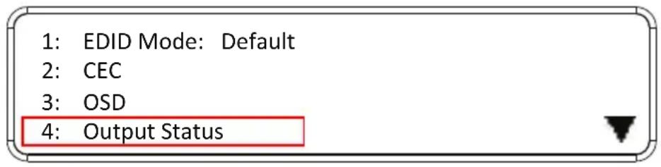
text_image
1: EDID Mode: Default 2: CEC 3: OSD 4: Output Status- Press pushbuttons 1–3 to select whether you want to configure the video, stereo audio, or output resolution for output ports.
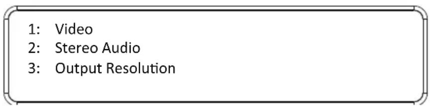
text_image
1: Video 2: Stereo Audio 3: Output Resolution- If configuring the output port status for video, press pushbuttons 1–16 to enable (ON) or disable (NA) the video channel:
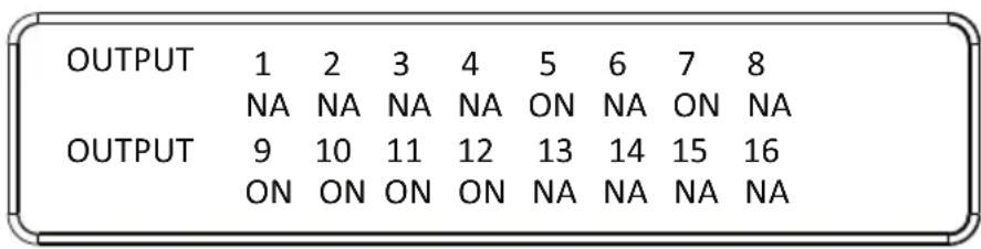
text_image
OUTPUT 1 2 3 4 5 6 7 8 NA NA NA NA ON NA ON NA OUTPUT 9 10 11 12 13 14 15 16 ON ON ON ON NA NA NA NANote: The default Output Status setting is On.
- If configuring the output port status for stereo audio, press pushbuttons 1–16 to select the output port. Adjust the audio volume for the port by pressing the Up or Down pushbutton:
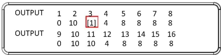
Note: The audio volume range from 0 (mute) and 1 (\~27dB) to 10 (0dB). The default audio volume is 10.
- If configuring the output video resolution, press pushbuttons 1–16 to select the output port. Next, select the preferred output resolution.
- Press Menu to return to the Menu page.
- Press Cancel to return to the previous step without saving.
Security Mode
The Security Mode page allows you to configure the VM1600A's password-related settings; the Password page sets the VM1600A to require a password for local operation after the LCD display times out (default time out: 5 minutes) or is powered off/on. The Change Password option allows you to set a new password for the VM1600A.
To configure the VM1600A's password settings from the Main Screen, use the Menu pushbutton to access the Menu page, then press pushbutton 4 to access the Security Mode page.
1: Mode
2: Change Password
Mode
- To set the VM1600A so that it requires a password for local operation, press pushbutton 1 in the Security Mode page.
1: Mode
2: Change Password
- To disable security settings, press pushbutton 1.
- To require a password after the LCD display times out or is powered off/on, press pushbutton 2.
- To enable a lock screen, press pushbutton 3. When Lock Screen is enabled, pressing any pushbutton from the home screen will trigger the following message: Please press "Menu" to start.
1: None
2: Password Enable
3: Lock Screen
Note: By default the password requirement is disabled. If the password is enabled, the LCD display's default time-out is 5 minutes.
- Press Menu to return to the Menu page.
- Press Cancel to return to the previous step without saving.
Change Password
- To change the password: from Security Mode, press pushbutton 2.

text_image
1: Mode 2: Change Password- In the Old Password field, the cursor flashes at the first digit. Enter the old password (see LCD Password, page 42). If the old password is entered correctly, you can proceed to the next step. The default password is: 1234.
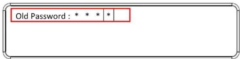
text_image
Old Password : * * * *Note: If you enter an incorrect password, the cursor goes back to the first digit and reverts to flashing. The Incorrect Password message clears as soon as a new digit is entered.
- In the New Password field, the cursor flashes at the first digit. Enter the new password using the front panel number pushbuttons (1111–9999).
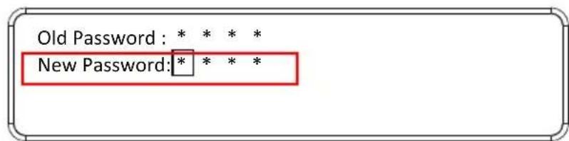
text_image
Old Password : * * * * New Password: * * * *- Re-enter the new password in the following screen. The new password is applied by the VM1600A immediately.
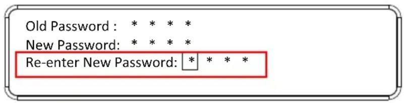
text_image
Old Password: * * * * New Password: * * * * Re-enter New Password: * * * *If the password you entered does not match the one entered in the previous screen, an error message appears. Enter the new password correctly.
-
Press Menu to return to the Menu page.
-
Press Cancel to return to the previous step without saving.
Save to a Profile
The VM1600A allows you to store up to 32 (P1–P32) different connection profiles that can be saved and recalled later. When profiles are saved, they are saved according to the current connection configuration on the Main Screen. When you load a profile, the change is immediate and the profile number is shown in the lower right corner of the LCD display. To save profiles, from the Main Screen do the following:
- Use the Menu pushbutton to access the Menu page, and Down to navigate to the next page. Press pushbutton 1 to open the Save to a Profile page.
1: Save to a Profile
2: Play/Stop the Profile Schedule
3: Turn Video Wall Off
- To save the active connection configuration as a profile use the front panel number pushbuttons to select a profile into which you want to save the configuration.
Save to a Profile: 1
(In1->16 = P1->16; Out1->16 = P17->P32.
Press Profile to save.)
- Input ports 1–16 correspond to Profile P1 to P16
-
Output ports 1–16 correspond to Profile P17 to P32
-
Press the Profile pushbutton to store the connection configuration – the LCD shows a Profile Saved message.
- Press Menu to return to the Menu page.
- Press Cancel to return to the previous step without saving.
Note: You can also access the Save to a Profile page by pressing the Profile pushbutton for longer than 3 seconds.
Play/Stop the Profile Schedule
Inputting port pushbutton 2 will Play or Stop the active Profile Schedule.
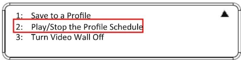
text_image
1: Save to a Profile 2: Play/Stop the Profile Schedule 3: Turn Video Wall OffTurn Video Wall Off
If a video wall is currently playing, a submenu will appear.
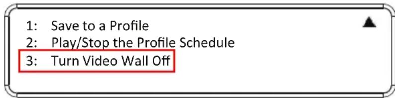
text_image
1: Save to a Profile 2: Play/Stop the Profile Schedule 3: Turn Video Wall OffSelecting Turn Video Wall Off will return port assignments to their default (i.e. disassemble the video wall).
This Page Intentionally Left Blank
Overview
The VM1600A can be configured over a standard TCP/IP connection via its built-in Graphical User Interface (GUI). Because it can be accessed from anywhere over a network or the Internet, operators can easily log in via web browser. Security is ensured by password protection and user-configurable time-out. The VM1600A supports three levels of remote users with various privileges, and up to 16 users can log into the GUI at one time. For full details see the sections that follow.
Logging In
To access the GUI, type the VM1600A's IP address into the address bar of any browser. If a Security Alert dialog box appears, accept the certificate – it can be trusted. The login screen appears:
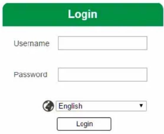
text_image
Login Username Password English Login◆ The default IP address is http://192.168.0.60
- The default Username and Password are: administrator / password
- Enter the username and password, then click Login.
◆ Use the drop-down menu to select the GUI language
Note: 1. The username supports lower case letters only.
- The same user can not be logged in simultaneously.
Main Page
The main page opens to Profile List. Use Profile List to configure the input to output connections by creating profiles, import or export profiles, or create a profile schedule. The page is divided into three parts: the Menu Bar, Profile List, and Profile Scheduling.
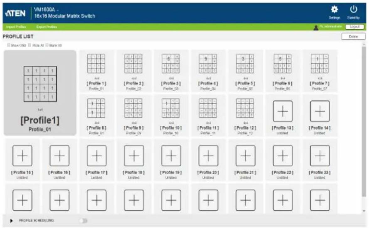
text_image
ATEN | VM1600A - 16x16 Modular Matrix Switch Import Profiles Export Profiles Profile List Show OSG Max Alt Bank Alt Profile1 Profile_01 Profile_01 Profile_02 Profile_02 Profile_03 Profile_03 Profile_04 Profile_04 Profile_05 Profile_05 Profile_06 Profile_06 Profile_07 Profile1 Profile_01 Profile_01 Profile_02 Profile_02 Profile_03 Profile_03 Profile_04 Profile_04 Profile_04 Profile_05 Profile_05 Profile_05 Profile_06 Profile_06 Profile_06 Profile_07 Profile1 Profile_01 Profile_01 Profile_02 Profile_02 Profile_03 Profile_03 Profile_04 Profile_04 Profile_04 Profile_05 Profile_05 Profile_05 Profile_06 Profile_06 Profile_06 Profile_07 profiles15 Untitled Profile16 Untitled Profile17 Untitled Profile18 Untitled Profile19 Untitled Profile20 Untitled Profile21 Untitled Profile22 Untitled Profile23 Untitled Profile SCHEDULINGMenu Bar
The Menu Bar provides the following controls:
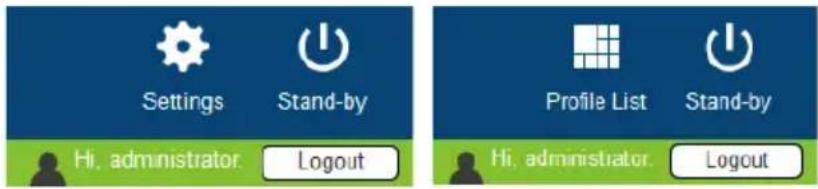
text_image
Settings Stand-by Hi, administrator Logout Profile List Stand-by Hi, administrator Logout| Control Description | |
| Settings Click to access the system settings. For details, see Adding a Recurring Playlist, page 90. | |
| Profile List Click to access settings on adding or editing profile adding/editing, profile import/export, and profile scheduling. For details, see Profile List, page 70. | |
| Standby Click to set the VM1600A to standby mode. For details, see Setting the Standby Mode, page 69. | |
| Logout Click to log out of the VM1600A web GUI. |
Setting the Standby Mode
The standby mode is a low-power mode where the VM1600A operates minimally by stopping all input and output transmissions and logging the user out of the web GUI.
To enable the standby mode, click from the menu bar in the VM1600A web GUI.
To disable the standby mode, do one of the following:
- Press the Menu pushbutton from the device panel
- Log in the web GUI with a valid credential
Profile List
The Profile List lets you create profile templates where the input to output port connections are defined. You can store up to 32 profiles that can be played manually or scheduled to be played for a specified time frame.
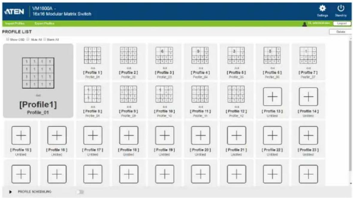
text_image
ATEN VM1600A - 16x16 Modular Matrix Switch Settings Stand-by Input Profiles Open Profiles Profile List Show OSD Multi AI Stark AI Profile 1 Profile_01 Profile_02 Profile_03 Profile_04 Profile_05 Profile_06 Profile_07 Profile 1 Profile_01 Profile_02 Profile_03 Profile_04 Profile_05 Profile_06 Profile_07 Profile 1 Profile_01 Profile_02 Profile_03 Profile_04 Profile_05 Profile_06 Profile_07 Profile 1 Profile_01 Profile_02 Profile_03 Profile 1 Profile_01 Profile_02 Profile_03 Profile 1 Profile_01 Profile_02 Profile 03 Profile 1 Profile_01 Profile_02 Profile 03 Profile 1 Profile_01 Profile 02 Profile 03 Profile 1 Profile_01 Profile 02 Profile 03 Profile 1 Profile_01 Profile 02 Profile 03 Profile 1 Profile_01 Profile 02 Profile 03 Profile 1 Profile_01 Profile 02 Profile 03 Profile 1 Profile_01 Profile 02 Profile_03 Profile 1 Profile_01 Profile 02 Profile 03 Profile 1 Profile_01 Profile 02 Profile 03 Profile 1 Profile_01 Profile 02 Profile 03 Profile 1 Profile_01 Profile 02 Profile 03 Profile 1 Profile_01 Profile 02 Profile 03 Profile.1 Profile.2 Profile.3 Profile.4 Profile.5 Profile.6 Profile.7 Profile.8 Profile.9 Profile.10 Profile.11 Profile.12 Profile.13 Profile.14 Profile.15 Profile.16 Profile.17 Profile.18 Profile.19 Profile.20 Profile.21 Profile.22 Profile.23 Profile SCHEDULINGCreating a Profile
- From the Profile List, click an empty profile + icon. This window appears.
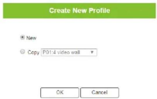
text_image
Create New Profile New Copy P01:4 video wall OK Cancel- Select New to create a new profile or Copy to use configuration from a pre-existing profile. This screen appears.
In this example, the profile is set to a quad view (2 x 2 divisions) using 16 displays.
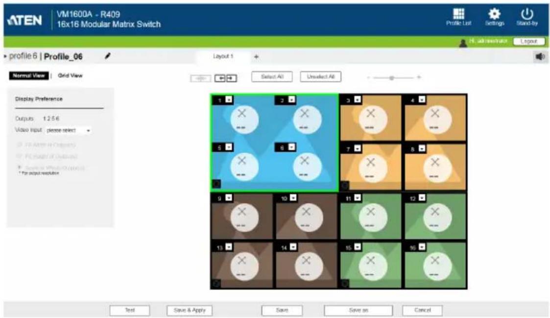
text_image
ATEN VM1600A - R409 16x16 Modular Matrix Switch Profile List Settings Stand-by H. ad-researcher Layout profile 6 | Profile_06 Layout 1 Normal View Grid View Select All Unselect All Display Preference Outputs 1:2:5:6 Video Input please select 18 (After) (Output) 19 (Invert) (Output) 20 (Invert) (Output) 21 (Invert) (Output) 22 (Invert) (Output) 23 (Invert) (Output) 24 (Invert) (Output) 25 (Invert) (Output) 26 (Invert) (Output) 27 (Invert) (Output) 28 (Invert) (Output) 29 (Invert) (Output) 30 (Invert) (Output) 31 (Invert) (Output) 32 (Invert) (Output) 33 (Invert) (Output) 34 (Invert) (Output) 35 (Invert) (Output) 36 (Invert) (Output) 37 (Invert) (Output) 38 (Invert) (Output) 39 (Invert) (Output) 40 (Invert) (Output) 41 (Invert) (Output) 42 (Invert) (Output) 43 (Invert) (Output) 44 (Invert) (Output) 45 (Invert) (Output) 46 (Invert) (Output) 47 (Invert) (Output) 48 (Invert) (Output) 49 (Invert) (Output) 50 (Invert) (Output) 51 (Invert) (Output) 52 (Invert) (Output) 53 (Invert) (Output) 54 (Invert) (Output) 55 (Invert) (Output) 56 (Invert) (Output) 57 (Invert) (Output) 58 (Invert) (Output) 59 (Invert) (Output) 60 (Invert) (Output) 61 (Invert) (Output) 62 (Invert) (Output) 63 (Invert) (Output) 64 (Invert) (Output) 65 (Invert) (Output) 66 (Invert) (Output) 67 (Invert) (Output) 68 (Invert) (Output) 69 (Invert) (Output) 70 (Invert) (Output) 71 (Invert) (Output) 72 (Invert) (Output) 73 (Invert) (Output) 74 (Invert) (Output) 75 (Invert) (Output) 76 (Invert) (Output) 77 (Invert) (Output) 78 (Invert) (Output) 79 (Invert) (Output) 80 (Invert) (Output) 81 (Invert) (Output) 82 (Invert) (Output) 83 (Invert) (Output) 84 (Invert) (Output) 85 (Invert) (Output) 86 (Invert) (Output) 87 (Invert) (Output) 88 (Invert) (Output) 89 (Invert) (Output) 90 (Invert) (Output) 91 (Invert) (Output) 92 (Invert) (Output) 93 (Invert) (Output) 94 (Invert) (Output) 95 (Invert) (Output) 96 (Invert) (Output) 97 (Invert) (Output) 98 (Invert) (Output) 99 (Invert) (Output) 100 (Invert) (Output)-
Click each monitor in the preview and define its video input and scaling preference.
-
To configure the total number of displays, view mode, and more, see Editing a Profile, page 73.
5. Click Save. This profile is added to the Profile List.
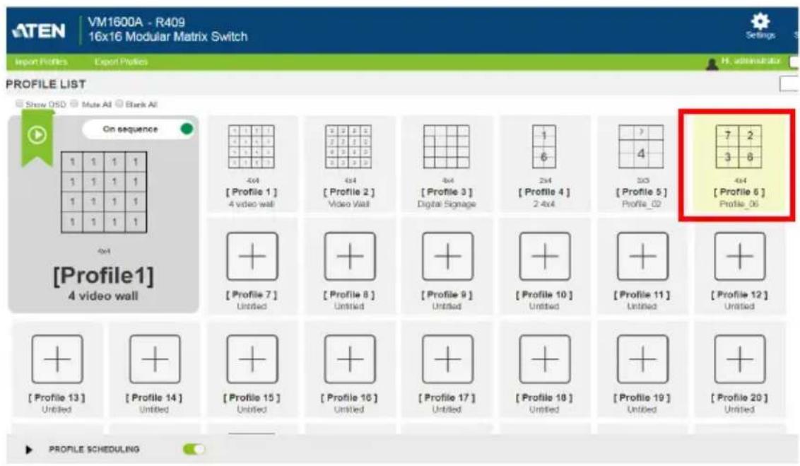
text_image
ATEN VM1600A - R409 16x16 Modular Matrix Switch Settings Import Profiles Export Profiles H. administrator PROFILE LIST Show OSD Mate AI Blank AI On sequence 1 1 1 1 1 1 1 1 1 1 1 1 1 1 1 1 4x4 [Profile 1] 4 video wall 4x4 [Profile 2] Video Visit 4x4 [Profile 3] Digital Signage 1 6 3x3 [Profile 4] 2 4x4 7 4 [Profile 5] Profile_02 4x4 [Profile 6] Profile_06 4x4 [Profile 1] 4 video wall + + [Profile 7] Untitled + + [Profile 8] Untitled + + [Profile 9] Untitled + + [Profile 10] Untitled + + [Profile 11] Untitled + + [Profile 12] Untitled + + [Profile 13] Untitled + + [Profile 14] Untitled + + [Profile 15] Untitled + + [Profile 16] Untitled + + [Profile 17] Untitled + + [Profile 18] Untitled + + [Profile 19] Untitled + + [Profile 20] Untitled PROFILE schedulingEditing a Profile
- Click a profile from the Profile List, and then click Edit. This screen appears.
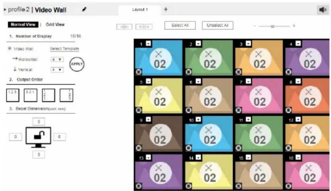
text_image
profile 2 | Video Wall Layout 1 Normal View | Grid View 1. Number of Display 16/16 Video Wall Select Template Horizontal: 4 Vertical: 4 2. Output Order 1.2 3 5.2 1 1 2. Bezel Dimension(unit: mm) 3. Bezel Dimension(unit: mm) 1 2 3 4 5 6 7 8 9 10 11 12 13 14 15 16 Select All Unselect All 02 02 02 02 02 02 02 02 02 02 02 02 02 02 02 02 02 02 02 02 02 02 02 02 02 02 02 02 02 02 02 02 02 02- You can choose either the Normal View or the Grid View to edit the profile.
Normal View
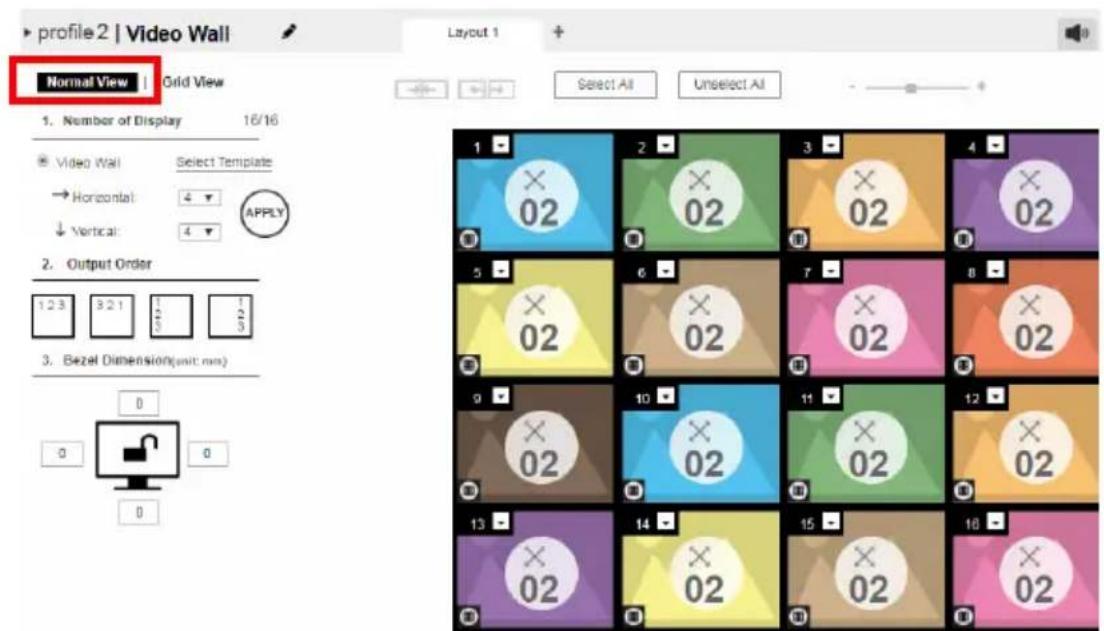
text_image
profile 2 | Video Wall Normal View Grid View 1. Number of Display 16/16 Video Wall Select Template → Horizontal: 4 ↓ Vertical: 4 2. Output Order 1 2 3 9 2 1 5 7 10 3. Bezel Dimension(unit: mm) 0 0 0 Layout 1 Select All Unselect All 1 2 3 4 5 6 7 8 9 10 11 12 13 14 15 16In a normal view, the profile is configured via a preview and a separate audio settings page that opens by clicking the audio icon at the top-right corner of the page.
- On top of video and audio assignments, the Normal View also allows you to configure the number of monitors and the bezel dimensions of the profile.
- For detailed information, see Editing a Profile in Normal View, page 75.
Grid View
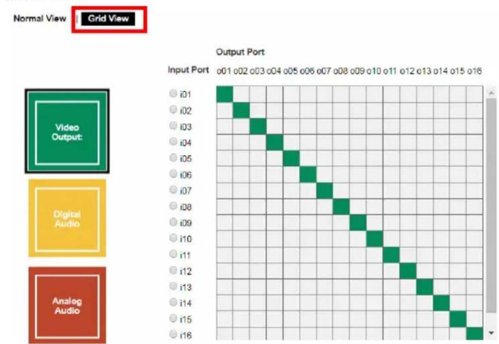
heatmap
| Input Port | o01 o02 o03 o04 o05 o06 o07 o08 o09 o10 o11 o12 o13 o14 o15 o16 | |---|---| | i01 | | | i02 | | | i03 | | | i04 | | | i05 | | | i06 | | | i07 | | | i08 | | | i09 | | | i10 | | | i11 | | | i12 | | | i13 | | | i14 | | | i15 | | | i16 | |-
In grid view, the audio and video outputs are assigned by mapping the audio/video input on the vertical axis to the audio/video output on a horizontal axis.
◆ For detailed information, see Editing a Profile in Grid View, page 84. -
(Optional) Click Test to apply your configuration without saving it.
- To save your configuration, click Save & Apply, Save, or Save As.
Editing a Profile in Normal View
Profile Layout Settings
Normal View | Grid View
- Number of Display 16/16
Video Wall
Select Template
→ Horizontal:

↓ Vertical:


- Output Order


- Bezel Dimension(unit: mm)
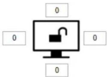
text_image
Diagram showing a computer monitor with an open padlock symbol and four empty boxes labeled '0' on both sides.| Control Description | |
| Number of Displays | Use the following controls to configure the layout type and the number of displays.◆Video Wall: Select this option for displays that are tiled together, where multiple monitors form one large screen – in various arrangements.◆Select Template: Click to open a window that allows you to select a predefined video wall layout.◆Horizontal / Vertical: Use these drop-down lists to select the number of displays that make up the video wall (a maximum of 64 are supported). Match this to the physical layout of the displays.Note: Click Apply to save the changes. A preview of the profile is shown on the right of the screen. |
| Output Order | Click any of the listed options to automatically assign output ports. |
| Bezel Dimension | Use the four boxes to increase/decrease the frame size for each active display. |
Monitor Lock / Unlock  | Click the monitor icon toLockthe (4) bezel settings, so that when one size is changed they all change.Click the monitor icon toUnlockthe (4) bezel settings, so that each size can be set independently. |
Display Preferences
To configure the display preferences for one or more displays, click the display(s) in the preview, the Display Preference settings page appears.
Configure the settings as required.
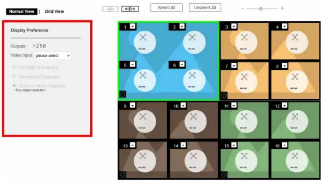
text_image
Normal View | Grid View Select All Unselect All Display Preference Outputs: 1 2 5 6 Video Input: please select Fill Width of Output(s) Fill Height of Output(s) Scale to Vehicle Output(s) For output resolution 1 2 3 4 5 6 7 8 9 10 11 12 13 14 15 16| Option Description | |
| Output This indicates the selected displays. | |
| Video Input Click to select a video source for the output(s). The chosen video source (port number) is indicated at the center of the output(s) in the preview. | |
| Radio Button | ◆ Fit Width of Output(s): fits the video to the width of the display.◆ Fit Height of Output(s): fits the video to the height of the display.◆ Scale to Whole Output(s): fits the video on the entire display. |
Video Wall Settings
Each icon represents an Output port and the connected display. Use the icons to create Independent and Grouped Outputs. Independent Outputs will display video on a single monitor. Grouped Outputs will display video across multiple monitors as one large screen.
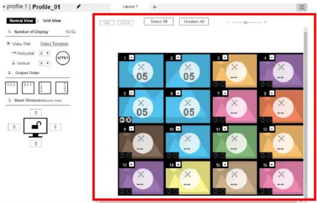
text_image
profile 1 | Profile_01 Normal View | Grid View 1. Number of Display 16/32 Video Wall Select Template → Horizontal: 4 ↓ Vertical: 4 2. Output Order 1 2 3 4 5 6 7 8 3. Bazei Dimension(unit: mm) 0 0 0 Layout 1 Select All Unselect All 1 2 3 4 5 6 7 8 9 10 11 12 13 14 15 16- Click an icon to choose its Output and Video Input from the Display Preference menu (see Video Wall Example 1, page 80).
- Click multiple icons to Group Outputs (see Grouping, page 79).
- Click Select All to select all outputs.
- Click Unselect All to unselect all outputs.
◆ Use the slider to zoom in and out of the display layout. -
On the Top Bar click:
-
to rename the profile
♦ + to add another layout to the profile
to configure audio outputs (Playing a Profile, page 86)
Null Input
natural_image
Blue background with a white circular icon containing an 'X' and a horizontal bar, no readable text or symbols.| Option Description | |
| Null Icon Click Null | Input icons to highlight icons in green and use the Display Preferences menu to set the video options (see Video Wall Example 1, page 80).Select a single icon to set the Output and Video Input for an independent display (see , page 78).Select multiple icons and set the Video Input to group displays as one screen (see Grouping, page 79). You must first set the Output port for each icon. |
| Drop-Down Menu | Use the drop-down menu to select the Output port. |
Independent Output
text_image
01| Option Description | |
| Independent | Independent Outputs are displays that have their ownVideo InputandOutputselected. Independent Outputs:◆ Display their own video◆ Icons have their own color and Video InputSelect an Independent Output and use theDisplay Preferences menu to select theVideo Input(see page 80). |
| Drop-down Menu | Use the drop-down menu (top-right corner) to select the Output port. |
Mute / Video  | Click thespeakericon to mute the audio on/off.Click thevideoicon to turn the video off/on. |
Grouping

natural_image
Simple graphic with a white circle containing an 'X' and a horizontal line, set against a blue background (no text or symbols)
natural_image
Green background with a white circular icon containing an 'X' and a minus sign, no readable text or symbols.
text_image
3 -
text_image
4 X --
natural_image
Simple graphic with a white circle containing an 'X' and a horizontal line, set against a yellow background with geometric shapes (no text or symbols)
natural_image
Simple icon with a circle containing an 'X' and a horizontal line, no text or symbols present.
natural_image
Pink background with a white circular icon containing an 'X' and a horizontal line, no readable text or symbols.
natural_image
Simple graphic icon with a white circle containing an 'X' and a horizontal line, set against an orange geometric background (no text or symbols)| Option Description | |
| Grouping Click m | multiple icons to Group Outputs (highlighted in green) and click →|← to group the displays into one screen. Use the Display Preferences menu to select the Video Input for the group - each Output icon in the Group will appear with the same Video Input number and icon color (see page 79). |
| Ungroup | Select a group and click ← → to ungroup the displays. |
Group
text_image
1 01 2 01| Option Description | |
| Group | A Group (of Outputs) shares the same Video Input and displays the video together as one large screen. A Group of Outputs:◆ Displays video across multiple monitors to form one screen◆ Icons have the same color and Video Input number.◆ Select a Group and use the Display Preferences menu to select the Video Input.◆ To group outputs see Grouping, page 79. |
Mute / Video | Click the speaker icon to mute the audio on/off.Click the video icon to turn the video off/on. |
Video Wall Example 1
The example below shows a video wall with 8 displays.
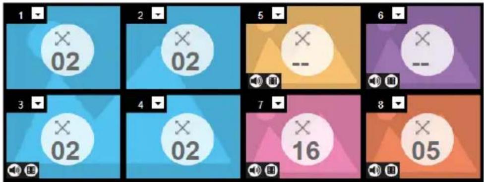
text_image
1 X 02 2 X 02 5 X -- 6 X -- 3 X 02 4 X 02 7 X 16 8 X 05◆ Each Group and Independent Output has a unique color.
- This video wall has 1 Group and 4 Independent displays.
- The Group will show Video Input 02 across all four displays as one large screen.
- The Independent displays will show the video from their own Video Input – 01, 07, 16 and 05.
- Add Display Layouts to create separate video walls (see Video Wall Settings, page 77).
Video Wall Example 2
The example below shows a video wall with 16 displays.
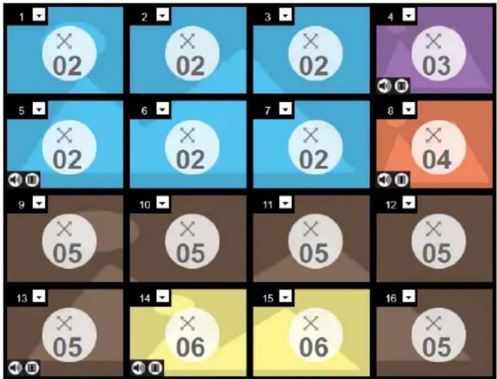
text_image
1 02 2 02 3 02 4 03 5 02 6 02 7 02 8 04 9 05 10 05 11 05 12 05 13 05 14 06 15 06 16 05◆ Each Group and Independent Output has a unique color.
- This video wall has 3 Groups and 2 Independent displays.
- The Blue Group will show Video Input 02 across six displays as one large screen.
- The Brown Group will show Video Input 05 across six displays as one large screen (as if Video Input 06 is a missing part of the entire screen).
- The Yellow Group will show Video Input 06 across two displays as one screen.
- The Orange and Purple Independent displays will show the video from their own Video Input – 03 and 04.
Audio Output Settings
Use this page to configure digital and analog audio output settings. To access these settings, click from the top-right corner in the profile settings page.
Digital Audio Output
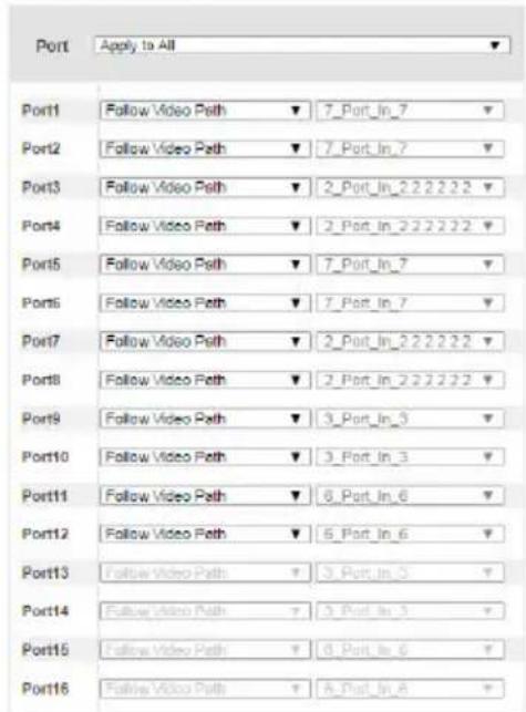
text_image
Port Apply to All Port1 Follow Video Path ▼ 7_Port_In_7 ▼ Port2 Follow Video Path ▼ 7_Port_In_7 ▼ Port3 Follow Video Path ▼ 2_Port_In_2 2 2 2 2 2 ▼ Port4 Follow Video Path ▼ 2_Port_In_2 2 2 2 2 2 ▼ Port5 Follow Video Path ▼ 7_Port_In_7 ▼ Port6 Follow Video Path ▼ 7_Port_In_7 ▼ Port7 Follow Video Path ▼ 2_Port_In_2 2 2 2 2 2 ▼ Port8 Follow Video Path ▼ 2_Port_In_2 2 2 2 2 2 ▼ Port9 Follow Video Path ▼ 3_Port_In_3 ▼ Port10 Follow Video Path ▼ 3_Port_In_3 ▼ Port11 Follow Video Path ▼ 6_Port_In_6 ▼ Port12 Follow Video Path ▼ 6_Port_In_6 ▼ Port13 Follow Video Path ▼ 3_Port_In_3 ▼ Port14 Follow Video Path ▼ 3_Port_In_3 ▼ Port15 Follow Video Path ▼ 8_Port_In_6 ▼ Port16 Follow Video Path ▼ 8_Port_In_6 ▼Analog Audio Output
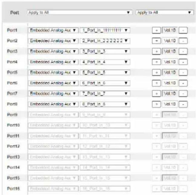
text_image
Port Apply to All Apply to All Port1 Embedded Analog Aux ▼ 1_Port_In_111111111 ▼ Port2 Embedded Analog Aux ▼ 2_Port_In_2222222 ▼ Port3 Embedded Analog Aux ▼ 3_Port_In_3 ▼ Port4 Embedded Analog Aux ▼ 4_Port_In_4 ▼ Port5 Embedded Analog Aux ▼ 5_Port_In_5 ▼ Port6 Embedded Analog Aux ▼ 6_Port_In_6 ▼ Port7 Embedded Analog Aux ▼ 7_Port_In_7 ▼ Port8 Embedded Analog Aux ▼ 8_Port_In_8 ▼ Port9 Embedded Analog Aux ▼ 9_Port_In_9 ▼ Port10 Embedded Analog Aux ▼ 10_Port_In_10 ▼ Port11 Embedded Analog Aux ▼ 11_Port_In_11 ▼ Port12 Embedded Analog Aux ▼ 12_Port_In_12 ▼ Port13 Embedded Analog Aux ▼ 13_Port_In_13 ▼ Port14 Embedded Analog Aux ▼ 14_Port_In_14 ▼ Port15 Embedded Analog Aux ▼ 15_Port_In_15 ▼ Port16 Embedded Analog Aux ▼ 16_Port_In_16 ▼
text_image
Port14 HDMI Use HDMI Audio Stereo Use Stereo Audio Vol 10 Port15 HDMI Use HDMI Audio Stereo Use Stereo Audio Vol 10 Port16 HDMI Use HDMI Audio Stereo Use Stereo Audio Vol 10- Digital Audio Output: Use this column to assign audio inputs to the digital audio outputs.
- Port: Use this field to apply the same audio setting to all digital audio output ports.
- All ports follow video path: Sets all digital audio outputs to receive the digital audio inputs that come with their video inputs as these videos display.
- All ports embedded analog audio: Sets all digital audio outputs to receive a specified embedded analog audio input.
- All mute: Mute all digital audio outputs.
- Port 1 - Port 16: Use these fields to assign different audio input for each digital audio output port.
- Follow video path: Sets the digital audio output port to receive the digital audio input that comes with the video input as it displays.
- Embedded Analog Audio: Sets the digital audio output port to receive the specified embedded analog audio input.
♦ Mute: Mutes the digital audio output for the port.
- Analog Audio Output: Use this column to assign audio inputs to the analog audio output ports.
- Port: Use this field to apply the same audio setting to all analog audio output ports.
- All ports follow video path: Sets all analog audio outputs to receive the digital audio inputs that come with their video inputs as these videos display.
- All ports embedded analog audio: Sets all analog audio outputs to receive a specified embedded analog audio input.
- All ports embedded digital audio: Sets all analog audio outputs to receive a specified digital audio input.
- All mute: Mute all analog audio outputs.
- Port 1 - Port 16: Use these fields to assign different audio input for each digital audio output port.
- Follow video path: Sets the analog audio output port to receive the digital audio input that comes with the video input as it displays.
- Embedded analog audio: Sets the analog audio output port to receive a specified embedded analog audio input.
- Embedded digital audio: Sets the analog audio output port to receive a specified digital audio input.
♦ Mute: Mute the analog audio output port.
Editing a Profile in Grid View
In a grid view, the audio and video outputs are assigned by mapping the audio/video input on the vertical axis to the audio/video output on a horizontal axis.
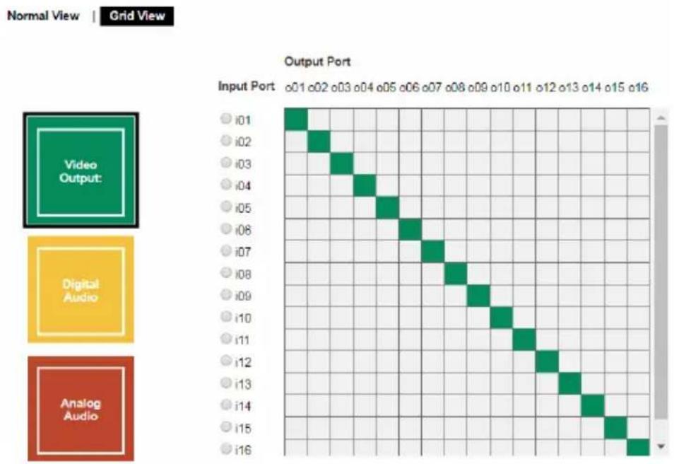
- Click Video Output, Digital Audio, Analog Audio to select the type of settings.
- Locate an input from the vertical axis and the output to which you wish from the horizontal axis, and then click the block in the grid where the input and output intercepts.
Example 1
In the following illustration, input 01 is assigned to output 01, and input 02 to output 02, and so forth.
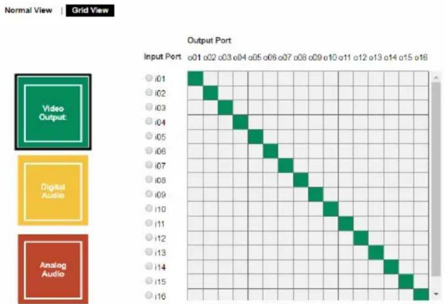
Example 2
To assign the same input for all outputs, click the input from the vertical axis. In the following illustration, all output ports are assigned with input 01.
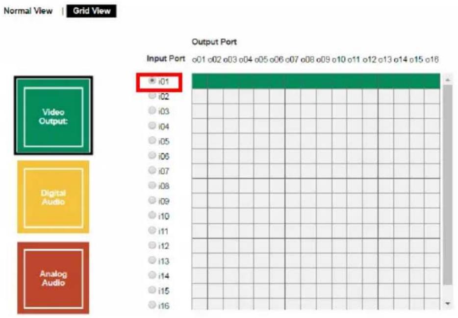
text_image
Normal View | Grid View Output Port Input Port o01 o02 o03 o04 o05 o06 o07 o08 o09 o10 o11 o12 o13 o14 o15 o16 Video Output: i01 i02 i03 i04 i05 i06 i07 i08 i09 i10 i11 i12 i13 i14 i15 i16Example 3
To have an audio output automatically switch to the audio input that comes along with the assigned video input, click AFV (audio following video). In this illustration, all digital audio output ports are set to follow their video input.
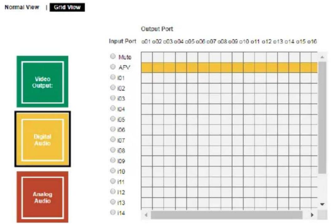
bar
| Input Port | Frequency | |---|---| | Mute | 01 | | AFV | 02 | | i01 | 03 | | i02 | 04 | | i03 | 05 | | i04 | 06 | | i05 | 07 | | i06 | 08 | | i07 | 09 | | i08 | 10 | | i09 | 11 | | i10 | 12 | | i11 | 13 | | i12 | 14 | | i13 | 15 | | i14 | 16 |Playing a Profile
- Click the profile you wish to apply and then click Apply.
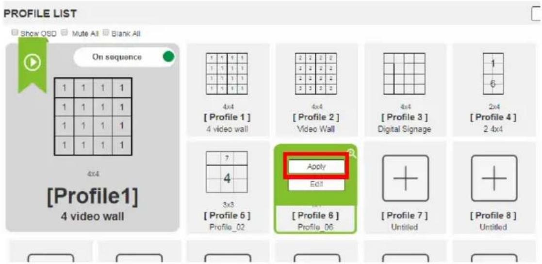
text_image
PROFILE LIST Show OSD Mute All Blank All On sequence 1 1 1 1 1 1 1 1 1 1 1 1 1 1 1 1 4x4 [Profile 1] 4 video wall 4x4 [Profile 2] Video Wall 4x4 [Profile 3] Digital Signage 2x4 [Profile 4] 2 4x4 3x3 [Profile 6] Profile_02 Apply Edit [Profile 6] Profile_06 [Profile 7] Untitled [Profile 8] Untitled- The profile is immediately applied and appears in the large Play window.
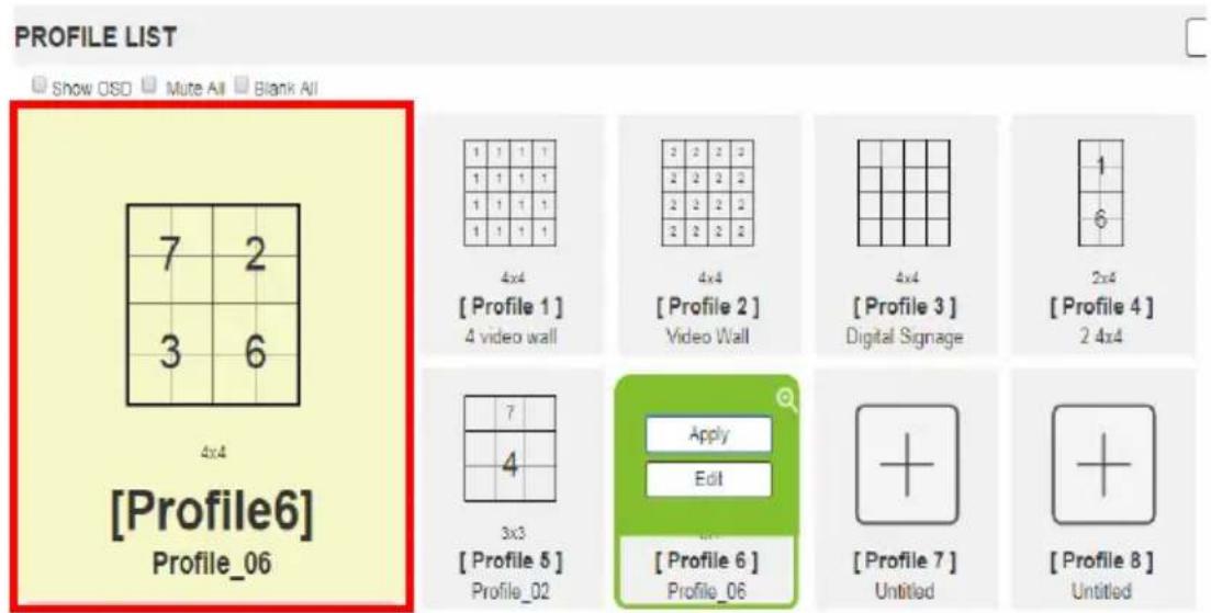
text_image
PROFILE LIST Show OSD Mute All Blank All 7 2 3 6 4x4 [Profile6] Profile_06 1 1 1 1 1 1 1 1 1 1 1 1 1 1 1 1 4x4 [Profile 1] 4 video wall 2 2 2 2 2 2 2 2 2 2 2 2 2 2 2 2 4x4 [Profile 2] Video Wall 4x4 [Profile 3] Digital Signage 1 6 2x4 [Profile 4] 2 4x4 7 4 3x3 [Profile 5] Profile_02 Apply Edit [Profile 6] Profile_06 + + [Profile 7] Untitled + [Profile 8] Untitled- To adjust the played profile, click on the Play window. The following controls appear.
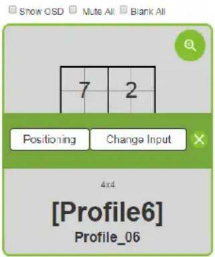
text_image
Show OSD Mute All Blank All 7 2 Positioning Change Input 4x4 [Profile6] Profile_06| Option Description | |
| Show OSD | Check Show OSD to show the current connection status via OSD. When Show OSD is unchecked, the OSD will disappear. |
| Mute All | Check Mute All to mute the audio for all ports. |
| Blank All | Check Blank All to turn off the video to all displays. |
| Click this icon to show a source assignment for this profile. | |
| On Sequence | On Sequence appears when a profile schedule is playing. |
| Positioning | Click Positioning to open a window that allows you to adjust the image position on each display. For Video Wall profiles, you can also set the Bezel Dimension, which is the frame thickness between each display. |
| Change Input | Click Change Input to change the input for single and grouped outputs, as explained on the next page. |
| Click this icon to delete the profile. | |
Importing/Exporting a Profile
To export the VM1600A's connection profiles, click Export Profiles. A configuration file starts downloading.
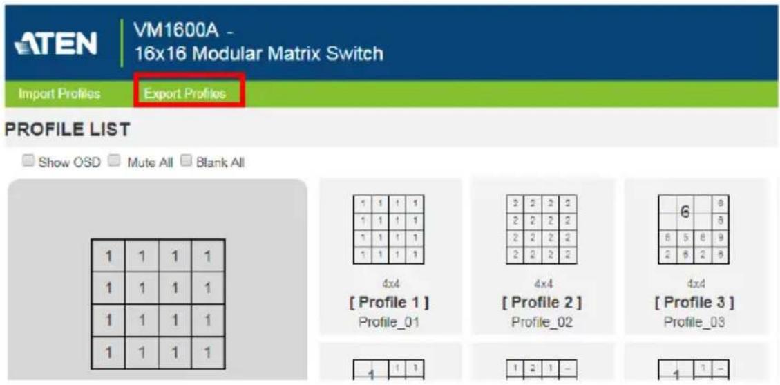
text_image
ATEN VM1600A - 16x16 Modular Matrix Switch Import Profiles Export Profiles PROFILE LIST Show OSD Mute All Blank All 1 1 1 1 1 1 1 1 1 1 1 1 1 1 1 1 1 1 1 1 4x4 [Profile 1] Profile_01 2 2 2 2 2 2 2 2 2 2 2 2 2 2 2 2 4x4 [Profile 2] Profile_02 6 8 6 5 8 9 2 8 2 8 4x4 [Profile 3] Profile_03 1 1 1 1 2 1 - 1 1 -To import connection profiles to the VM1600A, do the following:
- Click Import Profiles.
- Browse to the configuration file, select it and click Open.
Note: Importing a connection profile database will overwrite the current profiles.
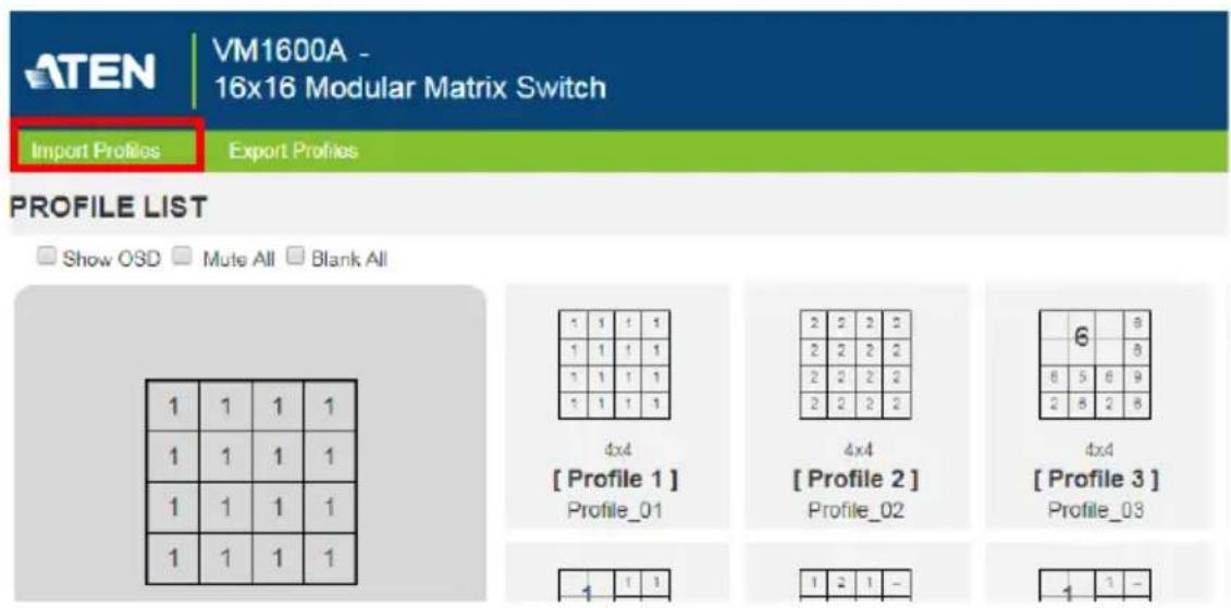
text_image
ATEN VM1600A - 16x16 Modular Matrix Switch Import Profiles Export Profiles PROFILE LIST Show OSD Mute All Blank All 1 1 1 1 1 1 1 1 1 1 1 1 1 1 1 1 1 1 1 1 4x4 [Profile 1] Profile_01 2 2 2 2 2 2 2 2 2 2 2 2 2 2 2 2 4x4 [Profile 2] Profile_02 6 8 6 5 6 9 2 8 2 8 4x4 [Profile 3] Profile_03 1 1 1 1 2 1 - 1 1 -Profile Scheduling
You can create one or more profile playlists that play periodically on specified time frames.
Enabling/Disabling Profile Schedule
To have the Matrix Switch play profile playlists, follow the steps below.
- Go to the Profile List page.
- Configure profile playlists. For details, see Adding Profile Playlists, page 90.
- From the Profile List page, click the PROFILE SCHEDULING toggle button to enable (green) or disable (gray) profile schedules.
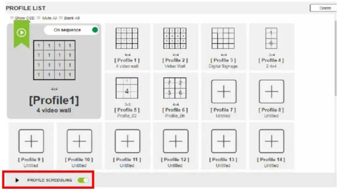
text_image
PROFILE LIST Show QED Mute All Blank All On sequence 1 1 1 1 1 1 1 1 1 1 1 1 1 1 1 1 4x4 [Profile 1] 4 video wall 4x4 [Profile 2] Video Wall 4x4 [Profile 3] Digital Signage 2x4 [Profile 4] 2 4x4 3x3 [Profile 5] Profile_02 7 2 $ 6 4x4 [Profile 6] Profile_06 + + [Profile 7] Untitled + + [Profile 8] Untitled + + [Profile 9] Untitled + + [Profile 10] Untitled + + [Profile 11] Untitled + + [Profile 12] Untitled + + [Profile 13] Untitled + + [Profile 14] Untitled ► PROFILE SCHEDULING DeleteNote: For firmware prior to version 4.2.416, if profile scheduling is disabled and re-enabled within the scheduled time frame of a playlist, the VM1600A will resume playing the first profile in the playlist; for VM1600A of firmware version 4.2.416 or later, the system will resume playing the playlist according to schedule, and the profiles that were to be played during the paused period will be skipped.
Adding Profile Playlists
Adding a Recurring Playlist
To add a playlist that plays periodically, follow the steps below.
- From the Profile List page, click PROFILE SCHEDULING. A profile calendar appears.
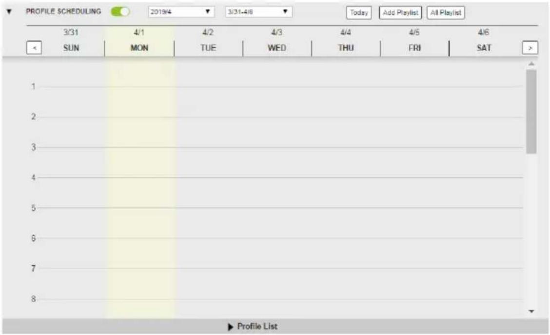
text_image
PROFILE SCHEDULING 2019/4 3/31-4/6 Today Add Playlist All Playlist 3/31 4/1 4/2 4/3 4/4 4/5 4/6 SUN MON TUE WED THU FRI SAT 1 2 3 4 5 6 7 8 Profile List- Click the Add Playlist button or a day on the calendar to add a playlist. The Add Playlist window appears.
Tip: Use the drop-down lists or the buttons from the top to adjust the calendar view.

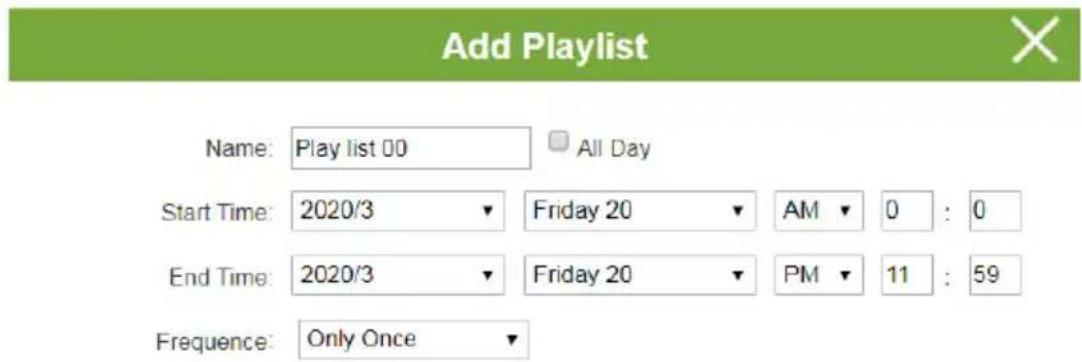
text_image
Add Playlist Name: Play list 00 All Day Start Time: 2020/3 ▼ Friday 20 ▼ AM ▼ 0 : 0 End Time: 2020/3 ▼ Friday 20 ▼ PM ▼ 11 : 59 Frequency: Only Once ▼
3. Configure the playlist.
a) Configure the Name, Start Time, End time, and Frequency.
b) Click □ to open the Select Profiles window. Click one or more profiles to add to the playlist.
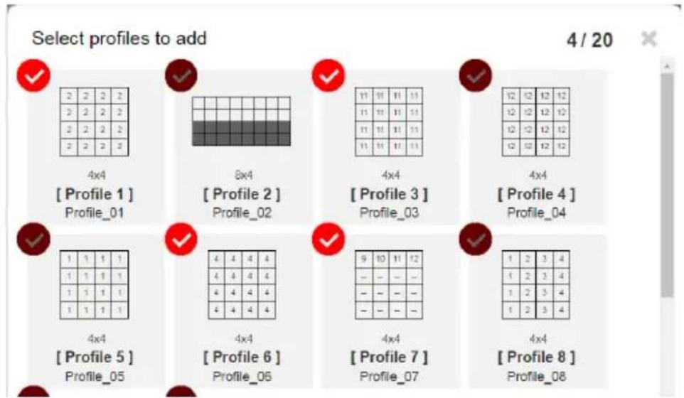
text_image
Select profiles to add 4 / 20 ✓ 2 2 2 2 3 2 2 2 2 2 2 2 3 2 2 2 4x4 [ Profile 1 ] Profile_01 8x4 [ Profile 2 ] Profile_02 4x4 [ Profile 3 ] Profile_03 4x4 [ Profile 4 ] Profile_04 ✓ 1 1 1 1 1 1 1 1 1 1 1 1 1 1 1 1 4x4 [ Profile 5 ] Profile_05 4x4 [ Profile 6 ] Profile_06 4x4 [ Profile 7 ] Profile_07 4x4 [ Profile 8 ] Profile_08c) Click OK. The selected profiles are added to the playlist. The profiles will be played from left to right.
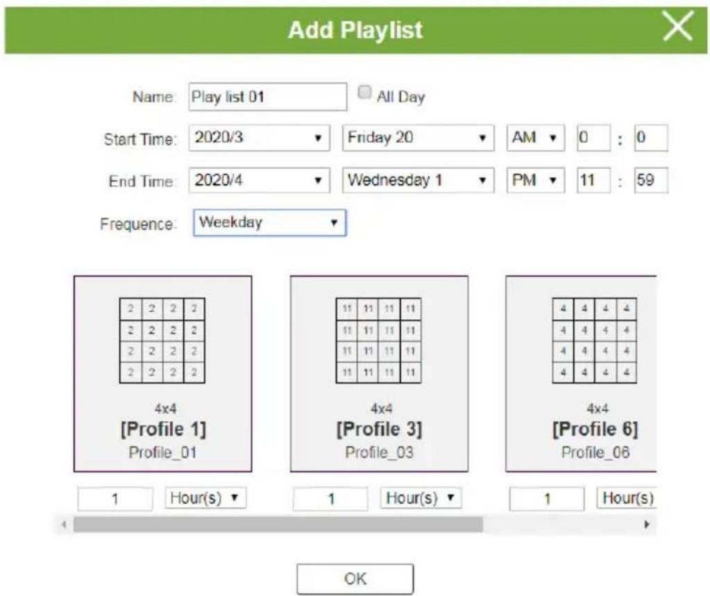
text_image
Add Playlist Name: Play list 01 All Day Start Time: 2020/3 ▼ Friday 20 ▼ AM ▼ 0 : 0 End Time: 2020/4 ▼ Wednesday 1 ▼ PM ▼ 11 : 59 Frequency: Weekday ▼ 4x4 [Profile 1] Profile_01 1 Hour(s) ▼ 1 Hour(s) ▼ 1 Hour(s) OKAdjust the play duration and the order of the added profiles if required. See the table below for more details.
| Option Description | |
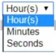 | Use the drop-down menu to select Hour(s), Minutes, or Seconds and then enter a duration (1-999) for the profile to play.Note: When the schedule switches to the next profile in the list. |
 | Use the drop-down menu to select Only Once, Every Day, Weekday or Every Week and then enter a duration (1-999) for the profile to play. After the time expires, the schedule switches to the next profile in the list. |
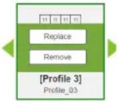 | To replace, remove, or change the order of a profile, click on a profile to access the Replace, Remove, and the <> buttons. |
Adding a One-off Profile Playlist
To add a playlist that plays once, follow the steps below.
- From the Profile List page, click PROFILE SCHEDULING. A profile calendar appears.
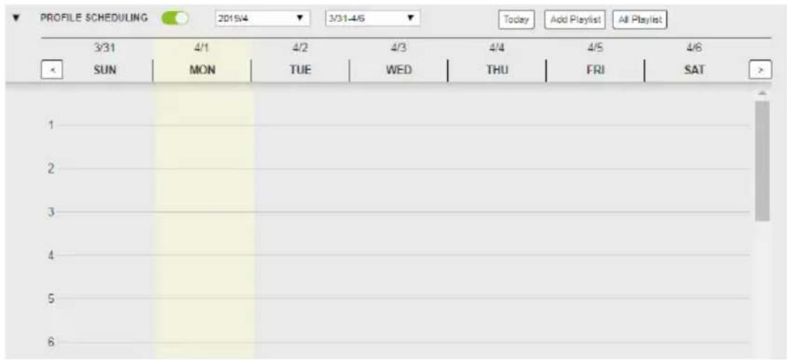
text_image
PROFILE SCHEDULING 2015/4 3/31-4/6 Today Add Playlist All Playlist 3/31 4/1 4/2 4/3 4/4 4/5 4/6 SUN MON TUE WED THU FRI SAT > 1 2 3 4 5 6- Use the buttons to adjust the calendar to a time frame to which you wish to add profiles.
- Click Profile List at the bottom of the page. The Profile List appears.
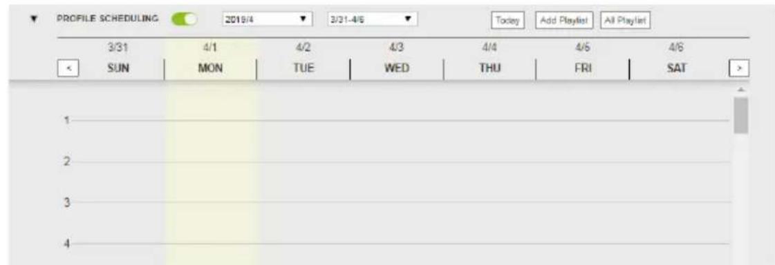
text_image
PROFILE SCHEDULING 2019/4 3/31-4/6 Today Add Playlist All Playlist 3/31 4/1 4/2 4/3 4/4 4/5 4/6 SUN MON TUE WED THU FRI SAT 1 2 3 4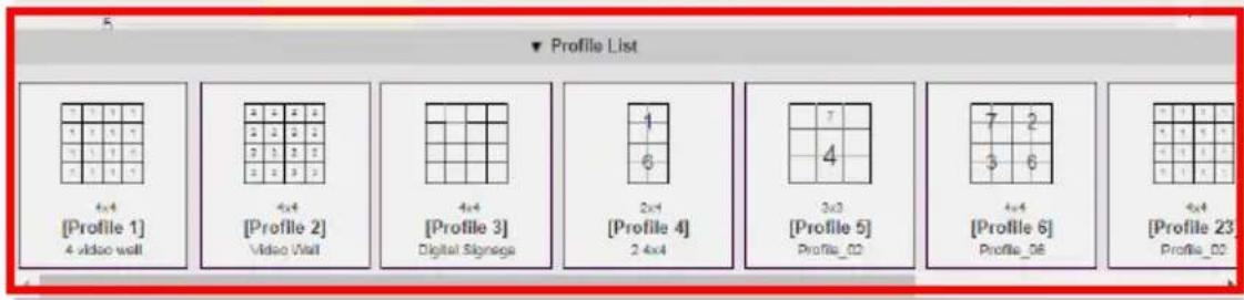
text_image
Profile List 4x4 [Profile 1] 4 video wall 4x4 [Profile 2] Video Wall 4x4 [Profile 3] Digital Signage 4x4 [Profile 4] 2.4x4 7 6 3x3 [Profile 5] Profile_02 7 2 5 6 4x4 [Profile 6] Profile_06 4x4 [Profile 23] Profile_02- From the Profile List, drag and drop profiles onto the desired time on the calendar view. Optionally right-click the profile to copy, remove, or view its settings.
Editing, Removing, or Copying Profile Playlists
To edit, remove, or copy profile playlists:
- Click the button from the Profile List page to open the All Playlist window.
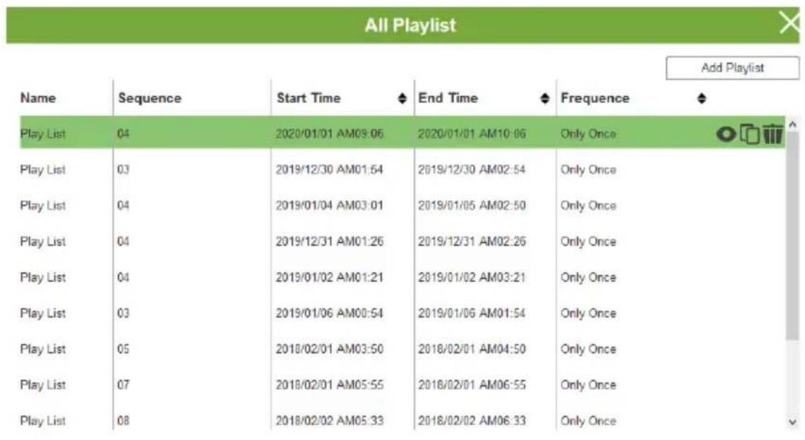
text_image
All Playlist Name Sequence Start Time End Time Frequency Play List 04 2020/01/01 AM09:06 2020/01/01 AM10:06 Only Once Play List 03 2019/12/30 AM01:54 2019/12/30 AM02:54 Only Once Play List 04 2019/01/04 AM03:01 2019/01/05 AM02:50 Only Once Play List 04 2019/12/31 AM01:26 2019/12/31 AM02:26 Only Once Play List 04 2019/01/02 AM01:21 2019/01/02 AM03:21 Only Once Play List 03 2019/01/06 AM00:54 2019/01/06 AM01:54 Only Once Play List 05 2018/02/01 AM03:50 2018/02/01 AM04:50 Only Once Play List 07 2018/02/01 AM05:55 2018/02/01 AM06:55 Only Once Play List 08 2018/02/02 AM05:33 2018/02/02 AM06:33 Only Once Add Playlist- Move the cursor to a playlist you want to edit, copy, or remove.
- Click one of the following buttons.
| Control Description | |
| Add Playlist | Click to add a new profile playlist. |
 View / Edit View / Edit | Click to edit or view the selected profile playlist. |
 Copy Copy | Click to create a copy of the selected profile playlist. |
 Remove Remove | Click to remove the selected profile playlist. |
System Settings
Overview
The setting pages allow you to configure the VM1600A's system settings.
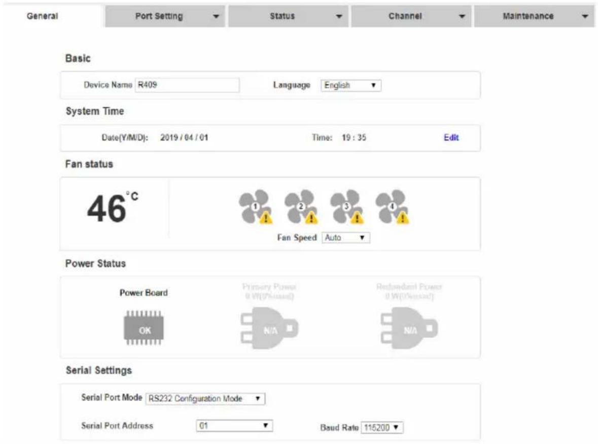
text_image
General Port Setting Status Channel Maintenance Basic Device Name R409 Language English System Time Date(Y/M/D): 2019/04/01 Time: 19:35 Edit Fan status 46°C 1 2 3 4 Fan Speed Auto Power Status Power Board Primary Power 0 W(0%used) Redundant Power 0 W(0%used) OK N/A NA Serial Settings Serial Port Mode RS232 Configuration Mode Serial Port Address 01 Baud Rate 115200If your Web GUI is not showing these settings, click the Settings icon from the top-right corner in the web interface.
text_image
Settings Stand-by Hi, administrator. LogoutThe table below provides an overview of the available settings for each tab.
| Tab Supported Functions Detailed Information | ||
| General | ◆ Configure the device name◆ Select the interface language◆ Monitor the VM1600A's fan temperature and configure the fan speed◆ Monitor the system's power status◆ Configure the settings for serial communications | For more information, see General, page 98. |
| Port Settings | ◆ Configure the OSD and CEC port settings◆ Configure the HDCP key for input and output ports◆ Configure the Seamless SwitchTM settings◆ Name the input and output ports◆ Select EDID modes | For more information, see Port Settings, page 100. |
| Status | ◆ View statuses of the input/output boards installed to the VM1600A and enable/ disable FrameSynce and Long Reach mode for the board.◆ View system information such as network settings, firmware version, and the settings for audio/video assignment, volume, CEC, audio mode settings, and more. | For more information, see YCBCR 4:2:0 Video Data Block, page 116. |
| Channel | ◆ Configure the IR routes for the input/ output boards.◆ Configure the RS-232 serial communication routes for the input/ output boards.Note: The IR/RS-232 Channel settings are only supported by VM7514/VM7584 Input Board or VM8514/VM8584 Output Board. | For more information, see Channel, page 120. |
| Maintenance | ◆ Upgrade the firmware for the installed input and output boards◆ Back up or restore the VM1600A's configuration◆ Add, edit, or remove user accounts◆ Configure the system network settings | See Maintenance, page 122. |
General
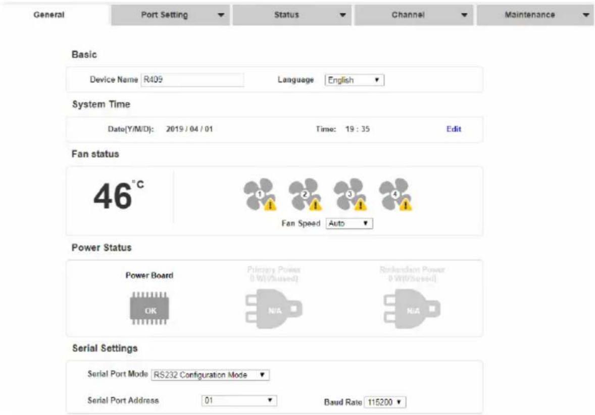
text_image
General Port Setting Status Channel Maintenance Basic Device Name R409 Language English System Time Date(Y/M/D): 2019/04/01 Time: 19:35 Edit Fan status 46°C 1 2 3 4 Fan Speed Auto Power Status Power Board Primary Power (1 W/V/Hz)# Renkendant Power (0 W/V/Hz)# OK N/A N/A Serial Settings Serial Port Mode RS232 Configuration Mode Serial Port Address 01 Baud Rate 115200Basics
◆ Device Name: Type to name your Modular Matrix Switch.
Language: Click to select a language for the web interface.
System Time
Click Edit to configure the system date and time settings.
Fan Status
◆ Fan speed: Click to select a fan speed.
- Temperature and fan icons: Indicates the internal temperature and status of the cooling fans. The fan icons rotate to indicate they are working.
Note: If the fans have stopped working or are switched off, they will appear as follows. The fan module will then need to be replaced or reset.

Power Status
This section displays the status and percentage used of the Primary and Redundant Power units.
Serial Settings
- Serial Port Mode: Defines the serial communications mode for the VM1600A.
- RS-232 Configuration Mode: Allows the user to configure VM1600A's system via RS-232 serial commands.
- RS-232 Control Mode: Allows the user to control remote devices that are connected to VM1600A through its RS-232 channels. To enable this feature, select the RS232 Control Mode and configure the input to output settings. For details, see Channel, page 120.
Note: To enable this feature, make sure to also configure the RS-232 channeling. For details, see Channel, page 120.
- RS-422/RS-485: If you are using RS422/RS485, define the Serial Port Address using the drop-down list.
- Serial Port Address: Defines the serial port address.
- Baud rate: Defines the baud rate for the serial port.
Port Settings
OSD/CEC
The OSD/CEC page lets users view and set OSD and CEC settings for all ports.
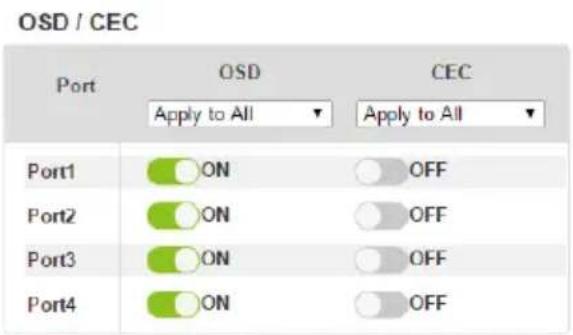
text_image
OSD / CEC Port OSD CEC Apply to All Apply to All Port1 ON OFF Port2 ON OFF Port3 ON OFF Port4 ON OFF* The GEC setting is only for outout boards, please make sure all devices have this capability.
- OSD: Sets the default OSD option for the port. When OSD is on, real-time text updates appear on the display for 10 seconds when configuration and port changes are made to its output.
- Use the drop-down menu to apply options to all ports, or ON/OFF button to enable/disable the OSD for each port.
- CEC: Consumer Electronics Control (CEC) allows interconnected HDMI devices to communicate and respond to one remote control.
- Use the drop-down menu to apply options to all ports, or On/Off button to enable/disable CEC for a port.
HDCP
The HDCP page lets users view and set HDCP key settings between input and output ports for digital copy protection and to ensure Seamless Switch ^™ is used between different devices. This is an Administrator and Advanced User only function.
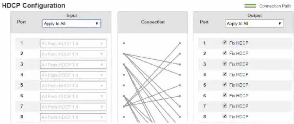
text_image
HDCP Configuration Port Input Apply to All 1 All Ports HDCP 1.4 2 All Ports HDCP 1.4 3 All Ports HDCP 1.4 4 All Ports HDCP 1.4 5 All Ports HDCP 1.4 6 All Ports HDCP 1.4 7 All Ports HDCP 1.4 8 All Ports HDCP 1.4 Connection • • • • • • • • • • • • • • • • • • • • • • • • • • • • • • • • • • • • • • • • • • • • • • • • • • Output Apply to All 1 ✓ Fix HDCP 2 ✓ Fix HDCP 3 ✓ Fix HDCP 4 ✓ Fix HDCP 5 ✓ Fix HDCP 6 ✓ Fix HDCP 7 ✓ Fix HDCP 8 ✓ Fix HDCPConnection
Here users can find a visual display of connection paths between inputs and outputs. When selecting an input, its path is displayed in green.
Output
Here users can define whether or not HDCP settings are fixed, either by individual port or by applying one setting to all ports. By prearranging and fixing keys, this setting ensures that Seamless Switch ^™ is possible even when switching between HDCP and non-HDCP enabled devices.
Scaler
The Video settings page allows you to set Seamless Switch ^™ options which determine how a display performs when the Input port is changed.
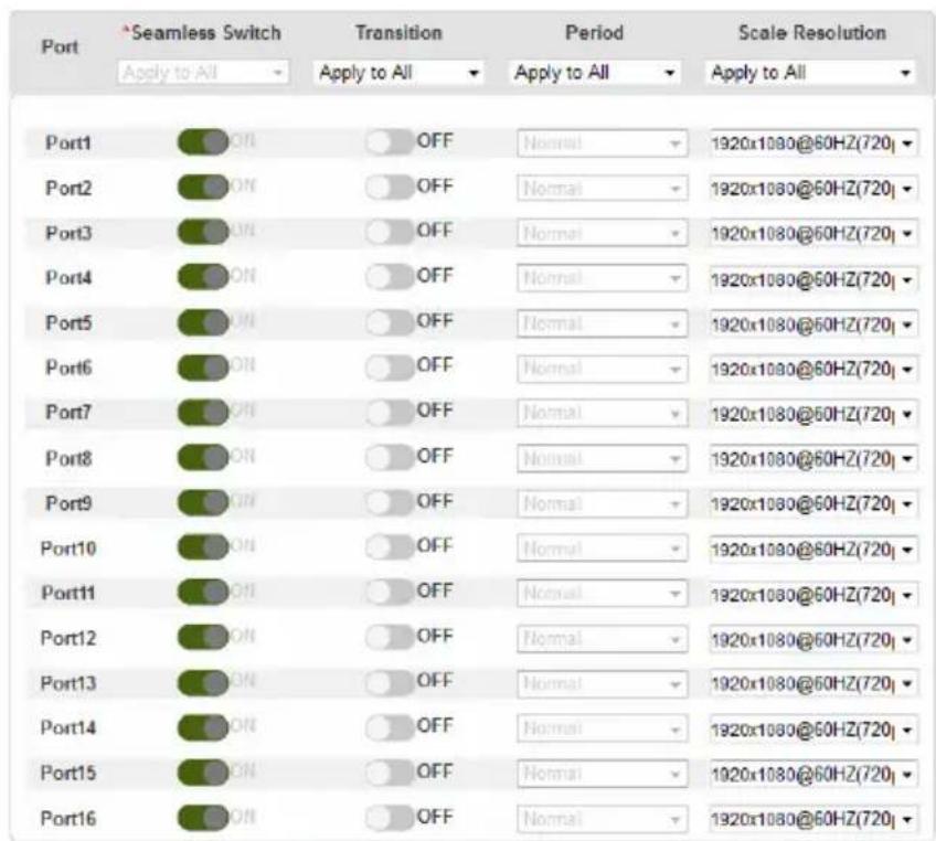
text_image
Port *Seamless Switch Apply to All Transition Apply to All Period Apply to All Scale Resolution Apply to All Port1 OFF Normal 1920x1080@60HZ(720) Port2 OFF Normal 1920x1080@60HZ(720) Port3 OFF Normal 1920x1080@60HZ(720) Port4 OFF Normal 1920x1080@60HZ(720) Port5 OFF Normal 1920x1080@60HZ(720) Port6 OFF Normal 1920x1080@60HZ(720) Port7 OFF Normal 1920x1080@60HZ(720) Port8 OFF Normal 1920x1080@60HZ(720) Port9 OFF Normal 1920x1080@60HZ(720) Port10 OFF Normal 1920x1080@60HZ(720) Port11 OFF Normal 1920x1080@60HZ(720) Port12 OFF Normal 1920x1080@60HZ(720) Port13 OFF Normal 1920x1080@60HZ(720) Port14 OFF Normal 1920x1080@60HZ(720) Port15 OFF Normal 1920x1080@60HZ(720) Port16 OFF Normal 1920x1080@60HZ(720)*Geamless switch can not be turned off at video wall edge
Note:
When Seamless Switch ^TM is enabled:
- The Transition, Period and Scale Resolution options can be enabled.
- Video outputs will not display 3D, Deep Color, or interlace (i.e., 1080i) resolutions correctly. To use these features, first disable Seamless Switch™.
- Videos may not display within range (fit on the screen), in which case, make sure to adjust the display settings on your device.
Enable Seamless Switch ^TM to remove the video distortion and delay seen when an input port is switched. Use the drop-down menu to apply options to all ports, or the On/Off button to enable/disable Seamless Switch ^TM per port. With Seamless Switch ^TM enabled, the following options are made available:
- Transition: Allows you to fade the video display when the Input port is changed. Use the period option to set the fade speed.
- Use the drop-down menu to apply options to all ports, or On/Off button to enable/disable Transition per port.
- Period: Sets the fade speed for the Transition option.
- Use the drop-down menu to apply an option (Slow, Normal, or Fast) to all ports, or lower drop-down menus to apply options per port.
- Scale Resolution: Forces the port to scale the video displayed to the selected resolution.
- Use the top drop-down menu to apply an option to all ports, or lower drop-down menus to apply options per port.
Port Name
The Annotation page lets users name the Input and Output ports for easy identification.
| Input Port | Output Port | ||
| 1 | 1_Port_In_11111111111111111111 | 1 | 1_Port_Out_1 |
| 2 | 2_Port_In_2 2 2 2 2 2 2 2 2 | 2 | 2_Port_Out_2 2 2 2 2 2 2 2 2 |
| 3 | 3_Port_In_3 | 3 | 3_Port_Out_3333333333333333333 |
| 4 | 4_Port_In_4 | 4 | 4_Port_Out_44444444444444444444 |
| 5 | 5_Port_In_6 | 5 | 5_Port_Out_555555555555555555555 |
| 6 | 6_Port_In_6 | 6 | 6_Port_Out_688888888888888888888888888888888888888888888888888888888888888888888888888888888888888888 |
| 7 | 7_Port_In_7 | 7 | 7_Port_Out_777777777777777777777777777777777777777777777777777777777777777777777 |
| 8 | 8_Port_In_0 | 8 | 8_Port_Out_88880000000000000000000000000000000000000000000000000000000000000000000000000000000000000000000000000000 |
| 9 | 9_Port_In_9 | 9 | 9_Port_Out_9 |
| 10 | 10_Port_In_10 | 10 | 10_Port_Out_10 |
| 11 | 11_Port_In_11 | 11 | 11_Port_Out_11 |
| 12 | 12_Port_In_12 | 12 | 12_Port_Out_12 |
| 13 | 13_Port_In_13 | 13 | 13_Port_Out_13 |
| 14 | 14_Port_In_14 | 14 | 14_Port_Out_14 |
| 15 | 15_Port_In_15 | 15 | 15_Port_Out_15 |
| 16 | 16_Port_In_16 | 16 | 16_Port_Out_16 |
- To name an Input/Output port, enter a descriptive name of up to 16 characters (including 0-9, a-z, A-Z, _, -) in the corresponding field.
- To change an Input/Output port's name, enter another value and click Save.
Note: The Input and Output port names can be the same.
EDID Settings
The EDID Setting page lets users view and select an EDID Mode so that the VM1600A can use the best resolution for its displays.
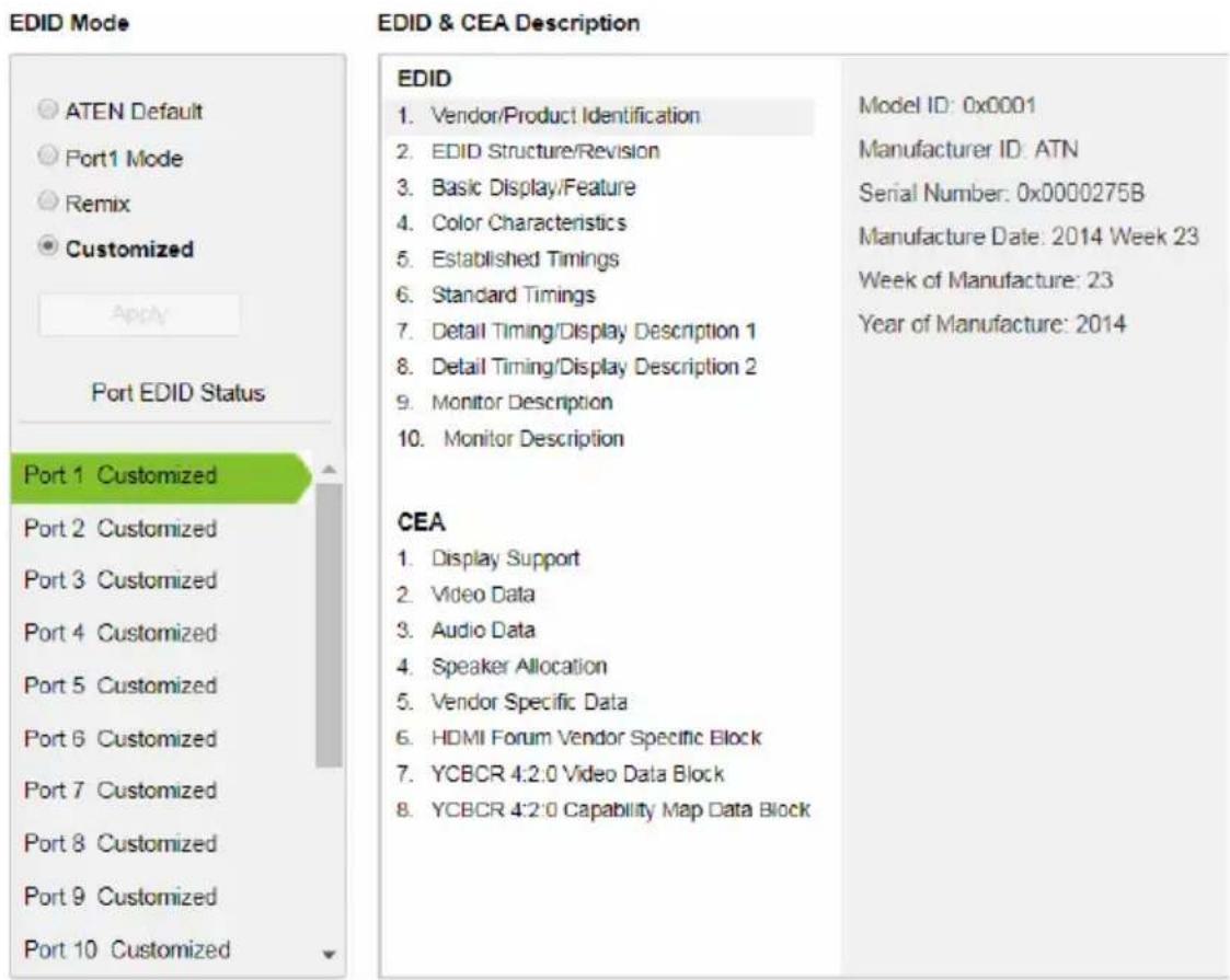
text_image
EDID Mode ATEN Default Port1 Mode Remix Customized Apply Port EDID Status Port 1 Customized Port 2 Customized Port 3 Customized Port 4 Customized Port 5 Customized Port 6 Customized Port 7 Customized Port 8 Customized Port 9 Customized Port 10 Customized EDID & CEA Description EDID 1. Vendor/Product Identification 2. EDID Structure/Revision 3. Basic Display/Feature 4. Color Characteristics 5. Established Timings 6. Standard Timings 7. Detail Timing/Display Description 1 8. Detail Timing/Display Description 2 9. Monitor Description 10. Monitor Description CEA 1. Display Support 2. Video Data 3. Audio Data 4. Speaker Allocation 5. Vendor Specific Data 6. HDMI Forum Vendor Specific Block 7. YCBCR 4:2:0 Video Data Block 8. YCBCR 4:2:0 Capability Map Data Block Model ID: 0x0001 Manufacturer ID: ATN Serial Number: 0x0000275B Manufacture Date: 2014 Week 23 Week of Manufacture: 23 Year of Manufacture: 2014Note: The EDID Mode can also be selected via the Front Panel pushbuttons – see Operation Mode, page 55.
Extended Display Identification Data (EDID) is a data format that contains a display's basic information and is used to communicate with the video source/system.
EDID Mode
In the left panel of the page, users can select a pre-configured EDID Mode using the EDID Mode radio buttons.
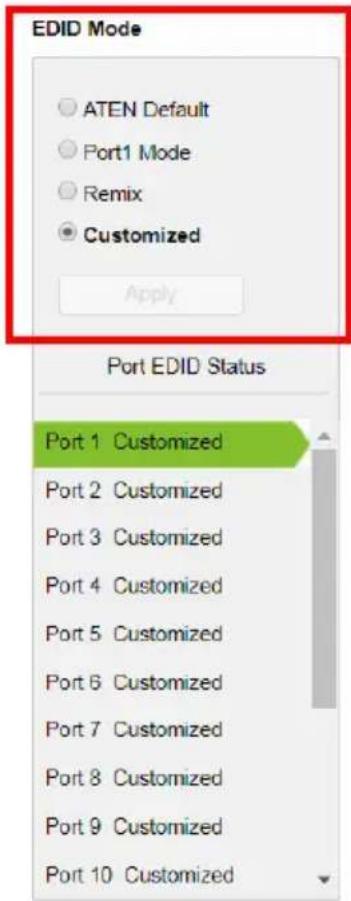
text_image
EDID Mode ○ ATEN Default ○ Port1 Mode ○ Remix ● Customized Apply Port EDID Status Port 1 Customized Port 2 Customized Port 3 Customized Port 4 Customized Port 5 Customized Port 6 Customized Port 7 Customized Port 8 Customized Port 9 Customized Port 10 CustomizedEDID & CEA Description
EDID
- Vendor/Product Identification
- EDID Structure/Revision
- Basic Display/Feature
- Color Characteristics
- Established Timings
- Standard Timings
- Detail Timing/Display Description 1
- Detail Timing/Display Description 2
- Monitor Description
- Monitor Description
CEA
- Display Support
- Video Data
- Audio Data
- Speaker Allocation
- Vendor Specific Data
- HDMI Forum Vendor Specific Block
- YCBCR 4.2.0 Video Data Block
- YCBCR 4:2:0 Capability Map Data Block
Model ID: 0x0001
Manufacturer ID: ATN
Serial Number: 0x0000275B
Manufacture Date: 2014 Week 23
Week of Manufacture: 23
Year of Manufacture: 2014
Select the EDID Mode to use and click Apply. The VM1600A uses the settings configured for that EDID mode.
Options are:
- ATEN Default: All ports' EDID is the same as the hardware default EDID.
◆ Port 1 Mode: All ports' EDID is the same as Port1's EDID.
♦ Remix: All ports' EDID uses the best display resolution. - Customized: See Customized Mode, see page 108.
EDID & CEA Description
The middle panel of the screen lets users view and configure the EDID or the CEA mode.
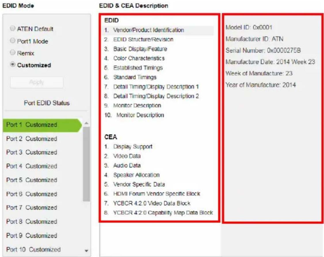
text_image
EDID Mode ATEN Default Port1 Mode Remix Customized Apply Port EDID Status Port 1 Customized Port 2 Customized Port 3 Customized Port 4 Customized Port 5 Customized Port 6 Customized Port 7 Customized Port 8 Customized Port 9 Customized Port 10 Customized EDID & CEA Description EDID 1. Vendor/Product Identification 2. EDID Structure/Revision 3. Basic Display/Feature 4. Color Characteristics 5. Established Timings 6. Standard Timings 7. Detail Timing/Display Description 1 8. Detail Timing/Display Description 2 9. Monitor Description 10. Monitor Description CEA 1. Display Support 2. Video Data 3. Audio Data 4. Speaker Allocation 5. Vendor Specific Data 6. HDMI Forum Vendor Specific Block 7. YCBCR 4:2.0 Video Data Block 8. YCBCR 4:2.0 Capability Map Data Block Model ID: 0x0001 Manufacturer ID: ATN Serial Number: 0x0000275B Manufacture Date: 2014 Week 23 Week of Manufacture: 23 Year of Manufacture: 2014- From the middle column, click the option that you want to view and/or edit. There are two categories: EDID (Extended Display Identification Data) and CEA (Consumer Electronics Association).
- When you select the menu items on the middle column, the current settings for the selected EDID appear on the right column. Some of the screens are read-only.
- For more information, see EDID Settings, page 105.
Customized Mode
Use the Customized mode to automatically retrieve and save the EDID of a connected monitor/display device to an input source port.
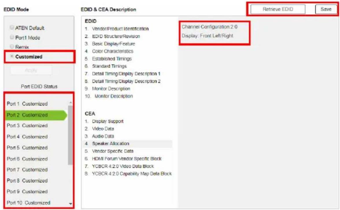
text_image
EDID Mode ATEN Default Port1 Mode Remix Customized Apply Port EDID Status Port 1 Customized Port 2 Customized Port 3 Customized Port 4 Customized Port 5 Customized Port 6 Customized Port 7 Customized Port 8 Customized Port 9 Customized Port 10 Customized EDID & CEA Description Retrieve EDID Save EDID 1. Vendor/Product Identification Channel Configuration 2.0 2. EDID Structure/Revision Display: Front Left/Right 3. Basic Display/Feature 4. Color Characteristics 5. Established Timings 6. Standard Timings 7. Detail Timing/Display Description 1 8. Detail Timing/Display Description 2 9. Monitor Description 10. Monitor Description CEA 1. Display Support 2. Video Data 3. Audio Data 4. Speaker Allocation 5. Vendor Specific Data 6. HDMI Forum Vendor Specific Block 7. YCBCR 4.2.0 Video Data Block 8. YCBCR 4.2.0 Capability Map Data Block- In the left panel, select Customized from the EDID Mode section and click Apply.
- Port EDID Status: Select the input source port to which you want to store the EDID configuration.
- Retrieve EDID: Click this button to retrieve the EDID of a selected port. Select a port using the pop-up screen.
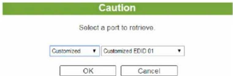
text_image
Caution Select a port to retrieve. Customized ▼ Customized EDID 01 ▼ OK Cancel- The right panel displays a summary of the acquired EDID settings that you can edit. Click Save and select the configuration for the Current Port or All Ports for the duration of the session.

text_image
Save Save changes to the current port or all ports? Current All Ports CancelCustomized EDID Parameters
The EDID structure is comprised of 128 bytes in total – each heading shown in the left column corresponds to a specific number of bytes.
The pages for the pre-configured EDID Modes (Port 1, Default and Remix) cannot be edited. The pages for the Customized EDID, which can be edited, are discussed in the proceeding sections:
Established Timings
This page lists video resolutions/timings that display devices can support.
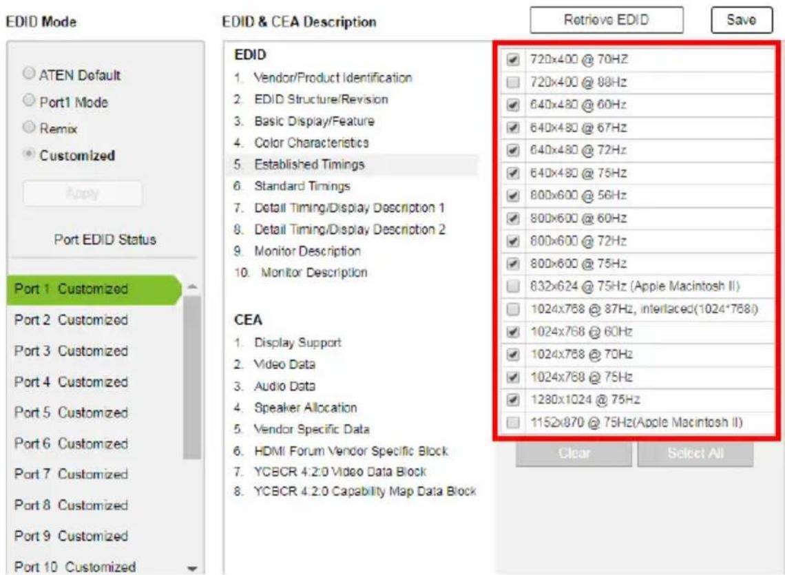
text_image
EDID Mode ATEN Default Port1 Mode Remix Customized Apply Port EDID Status Port 1 Customized Port 2 Customized Port 3 Customized Port 4 Customized Port 5 Customized Port 6 Customized Port 7 Customized Port 8 Customized Port 9 Customized Port 10 Customized EDID & CEA Description Retrieve EDID Save EDID 1. Vendor/Product Identification 2. EDID Structure/Revision 3. Basic Display/Feature 4. Color Characteristics 5. Established Timings 6. Standard Timings 7. Detail Timing/Display Description 1 8. Detail Timing/Display Description 2 9. Monitor Description 10. Monitor Description CEA 1. Display Support 2. Video Data 3. Audio Data 4. Speaker Allocation 5. Vendor Specific Data 6. HDMI Forum Vendor Specific Block 7. YCBCR 4:2:0 Video Data Block 8. YCBCR 4:2:0 Capability Map Data Block 720x400 @ 70Hz 720x400 @ 80Hz 640x480 @ 60Hz 640x480 @ 67Hz 640x480 @ 72Hz 640x480 @ 75Hz 800x600 @ 56Hz 800x600 @ 60Hz 800x600 @ 72Hz 800x600 @ 75Hz 832x624 @ 75Hz (Apple Macintosh II) 1024x768 @ 87Hz, interlaced(1024*768) 1024x768 @ 60Hz 1024x768 @ 70Hz 1024x768 @ 75Hz 1280x1024 @ 75Hz 1152x870 @ 75Hz(Apole Macintosh II) Clear Select All- Select the resolution(s) you want to use for the attached monitor/display device.
- Click Clear All to unselect all the items.
- Click Select All to check all the items.
- Click Save to apply the changes.
Standard Timings
This page shows eight resolutions/timings that display devices can support in addition to those listed in the Established Timings page.
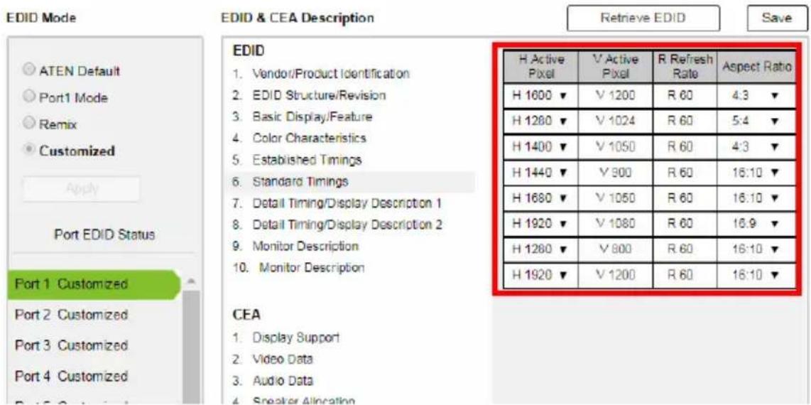
text_image
EDID Mode ATEN Default Port1 Mode Remix Customized Apply Port EDID Status Port 1 Customized Port 2 Customized Port 3 Customized Port 4 Customized EDID & CEA Description Retrieve EDID Save EDID 1. Vendor/Product Identification 2. EDID Structure/Revision 3. Basic Display/Feature 4. Color Characteristics 5. Established Timings 6. Standard Timings 7. Detail Timing/Display Description 1 8. Detail Timing/Display Description 2 9. Monitor Description 10. Monitor Description H Active Pixel V Active Pixel R Refresh Rate Aspect Ratio H 1000 ▼ V 1200 R 60 4:3 ▼ H 1280 ▼ V 1024 R 60 5:4 ▼ H 1400 ▼ V 1050 R 60 4:3 ▼ H 1440 ▼ V 900 R 60 16:10 ▼ H 1680 ▼ V 1050 R 60 16:10 ▼ H 1920 ▼ V 1080 R 60 16:9 ▼ H 1280 ▼ V 900 R 60 16:10 ▼ H 1920 ▼ V 1200 R 60 16:10 ▼ CEA 1. Display Support 2. Video Data 3. Audio Data 4. Speaker Allocation- Select the H Active Pixel from the drop-down menu.
- Select the Aspect Ratio from the drop-down menu.
- Click Save to apply the changes.
Detail Timing / Display Description
This screen gives more video resolution options, and provides resolution/timing details.
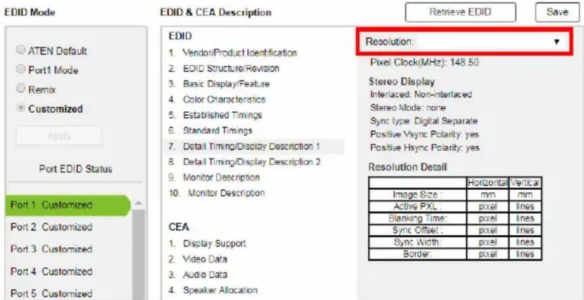
text_image
EDID Mode ATEN Default Port1 Mode Remix Customized Apply Port EDID Status Port 1 Customized Port 2 Customized Port 3 Customized Port 4 Customized Port 5 Customized EDID & CEA Description Vendor/Product Identification EDID Structure/Revision Basic Display/Feature Color Characteristics Established Timings Standard Timings Detail Timing/Display Description 1 Detail Timing/Display Description 2 Monitor Description Monitor Description CEA Display Support Video Data Audio Data Speaker Allocation Resolution: Pixel Clock(MHz): 148.50 Stereo Display Interlaced: Non-interlaced Stereo Mode: none Sync type: Digital Separate Positive Vsync Polarity: yes Positive Hsync Polarity: yes Resolution Detail Horizontal Vertical Image Size: mm mm Active PXL: pixel Ines Blanking Time: pixel Ines Sync Offset: pixel Ines Sync Width: pixel Ines Border: pixel InesIn the drop down menu, choose a resolution with values that fit the attached monitor/display device and click Save.
Monitor Description
This screen lets you specify the viewing specifications, namely horizontal and vertical scan ranges and pixel clock rate, of your monitor/display device.
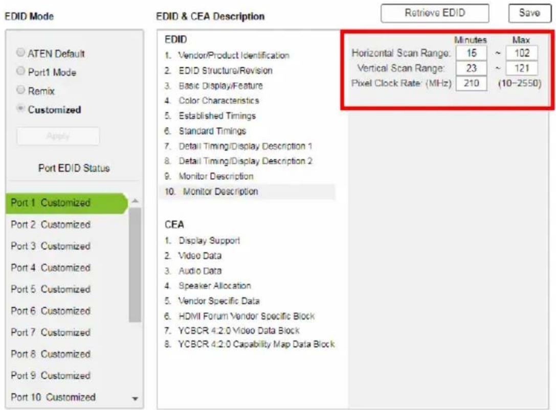
text_image
EDID Mode ATEN Default Port1 Mode Remix Customized Apply Port EDID Status Port 1 Customized Port 2 Customized Port 3 Customized Port 4 Customized Port 5 Customized Port 6 Customized Port 7 Customized Port 8 Customized Port 9 Customized Port 10 Customized EDID & CEA Description Retrieve EDID Save EDID 1. Vendor/Product Identification 2. EDID Structure/Revision 3. Basic Display/Feature 4. Color Characteristics 5. Established Timings 6. Standard Timings 7. Detail Timing/Display Description 1 8. Detail Timing/Display Description 2 9. Monitor Description 10. Monitor Description CEA 1. Display Support 2. Video Data 3. Audio Data 4. Speaker Allocation 5. Vendor Specific Data 6. HDMI Forum Vendor Specific Block 7. YCBCR 4.2.0 Video Data Block 8. YCBCR 4.2.0 Capability Map Data Block Minutes Max Horizontal Scan Range: 15 ~ 102 Vertical Scan Range: 23 ~ 121 Pixel Clock Rate (MHz) 210 (10-2550)Enter the values that correspond to your device and click Save to apply the changes.
CEA Settings
CEA is an extension data of the EDID structure, which further extends the standard definitions of EDID to support advanced features of monitors/display devices.
Display Support
This screen describes the display's basic digital components.
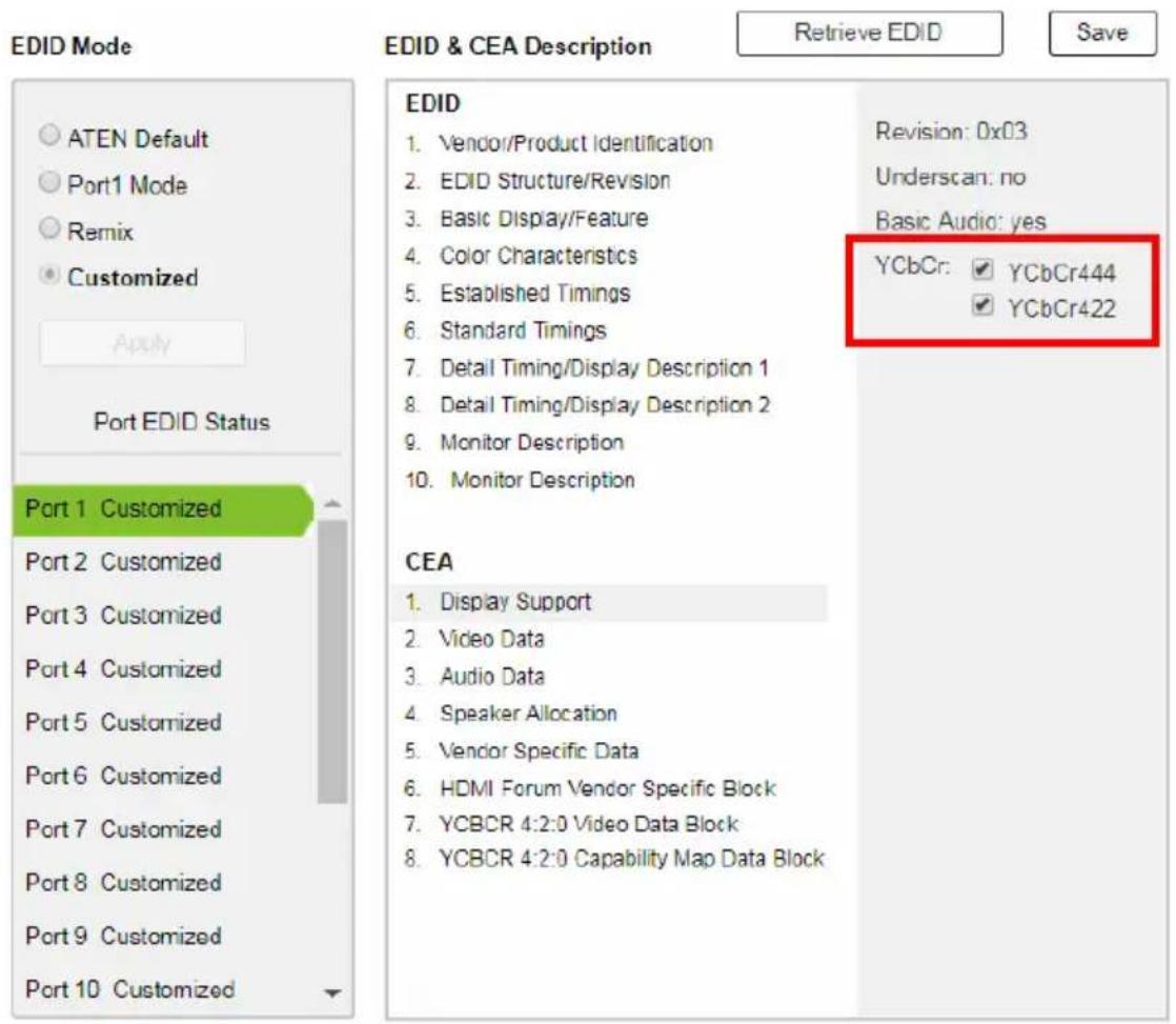
text_image
EDID Mode ATEN Default Port1 Mode Remix Customized Apply Port EDID Status Port 1 Customized Port 2 Customized Port 3 Customized Port 4 Customized Port 5 Customized Port 6 Customized Port 7 Customized Port 8 Customized Port 9 Customized Port 10 Customized EDID & CEA Description Retrieve EDID Revision: 0x03 Underscan: no Basic Audio: yes YCbCr: ✓ YCbCr444 ✓ YCbCr422 CEA Display Support Video Data Audio Data Speaker Allocation Vendor Specific Data HDMI Forum Vendor Specific Block YCBCR 4:2:0 Video Data Block YCBCR 4:2:0 Capability Map Data BlockSelect the YCbCr mode applicable to your display and click Save.
Video Data
This screen lists additional video resolution/timing displays that may be supported by other devices, other than PC monitors (for example, 1080i).
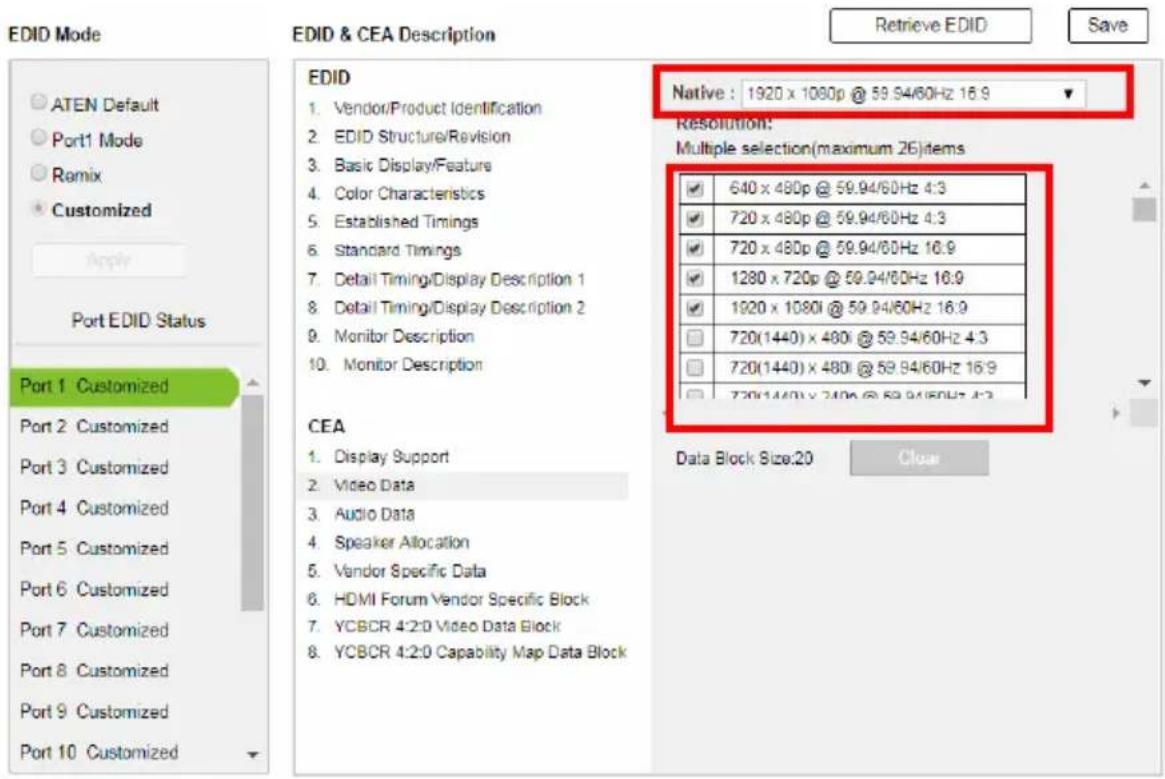
text_image
EDID Mode ATEN Default Port1 Mode Romix Customized Apply Port EDID Status Port 1 Customized Port 2 Customized Port 3 Customized Port 4 Customized Port 5 Customized Port 6 Customized Port 7 Customized Port 8 Customized Port 9 Customized Port 10 Customized EDID & CEA Description Retrieve EDID Save EDID 1. Vendor/Product Identification 2. EDID Structure/Revision 3. Basic Display/Feature 4. Color Characteristics 5. Established Timings 6. Standard Timings 7. Detail Timing/Display Description 1 8. Detail Timing/Display Description 2 9. Monitor Description 10. Monitor Description CEA 1. Display Support 2. Video Data 3. Audio Data 4. Speaker Allocation 5. Vendor Specific Data 6. HDMI Forum Vendor Specific Block 7. YCBCR 4:2:0 Video Data Block 8. YCBCR 4:2:0 Capability Map Data Block Native : 1920 x 1080p @ 59.94/60Hz 16.9 Resolution: Multiple selection(maximum 26)items ✓ 640 x 480p @ 59.94/60Hz 4:3 ✓ 720 x 480p @ 59.94/60Hz 4:3 ✓ 720 x 480p @ 59.94/60Hz 16.9 ✓ 1280 x 720p @ 59.94/60Hz 16.9 ✓ 1920 x 1080i @ 59.94/60Hz 16.9 ☐ 720(1440) x 480i @ 59.94/60Hz 4:3 ☐ 720(1440) x 480i @ 59.94/60Hz 16.9 ☐ 720(1440) x 240p @ 59.94/60Hz 4:3 Data Block Size:20 Clear- Select the native resolution of the attached display device.
- Select the resolutions that work with the attached monitor/display device.
- Click Clear All to deselect all the items.
- Click Save to apply the changes.
Audio Data
This screen lets you select advanced audio configurations for your device.
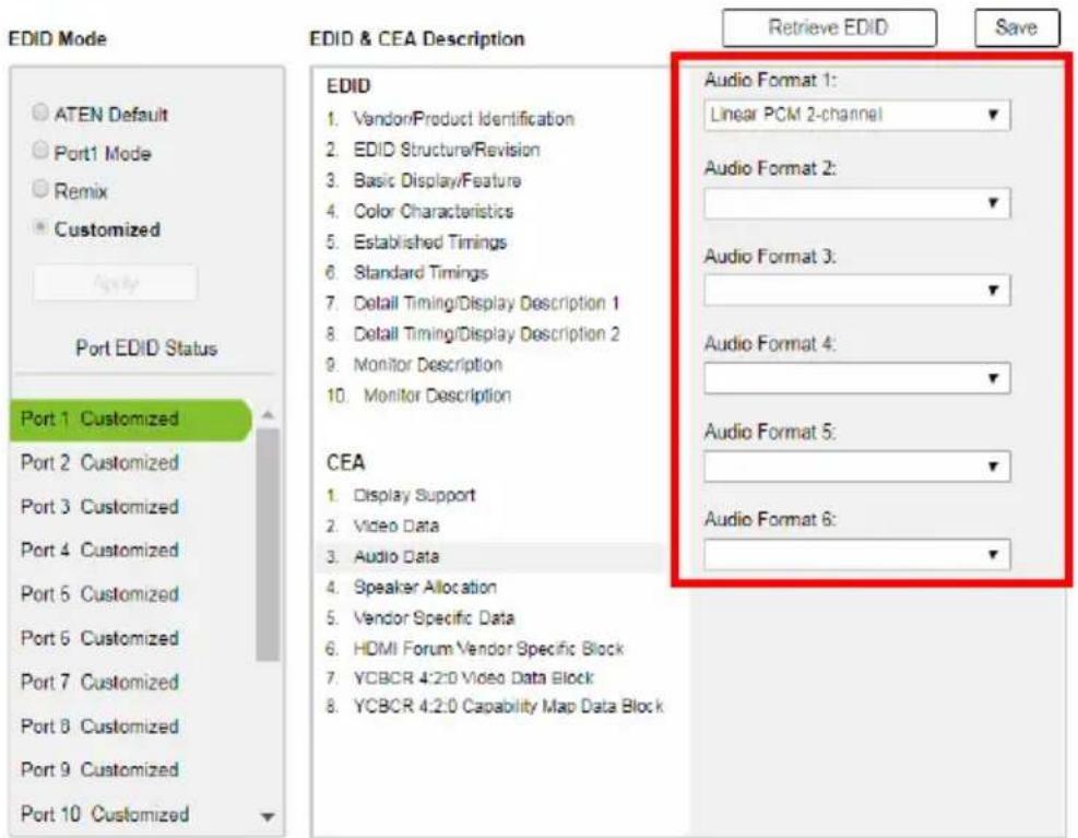
text_image
EDID Mode ATEN Default Port1 Mode Remix Customized Port EDID Status Port 1 Customized Port 2 Customized Port 3 Customized Port 4 Customized Port 5 Customized Port 6 Customized Port 7 Customized Port 8 Customized Port 9 Customized Port 10 Customized EDID & CEA Description Audio Format 1: Linear PCM 2-channel Audio Format 2: Audio Format 3: Audio Format 4: Audio Format 5: Audio Format 6: CEA Display Support Video Data Audio Data Speaker Allocation Vendor Specific Data HDMI Forum Vendor Specific Block VCBCR 4:2:0 Video Data Block VCBCR 4:2:0 Capability Map Data BlockUse the drop down menu to select the Audio Format (1\~6) applicable to your audio output device, and click Save to apply the changes.
HDMI Forum Vendor Specific Block
This screen shows the display device's supported video parameters. Use the toggle button to enable or disable this function.
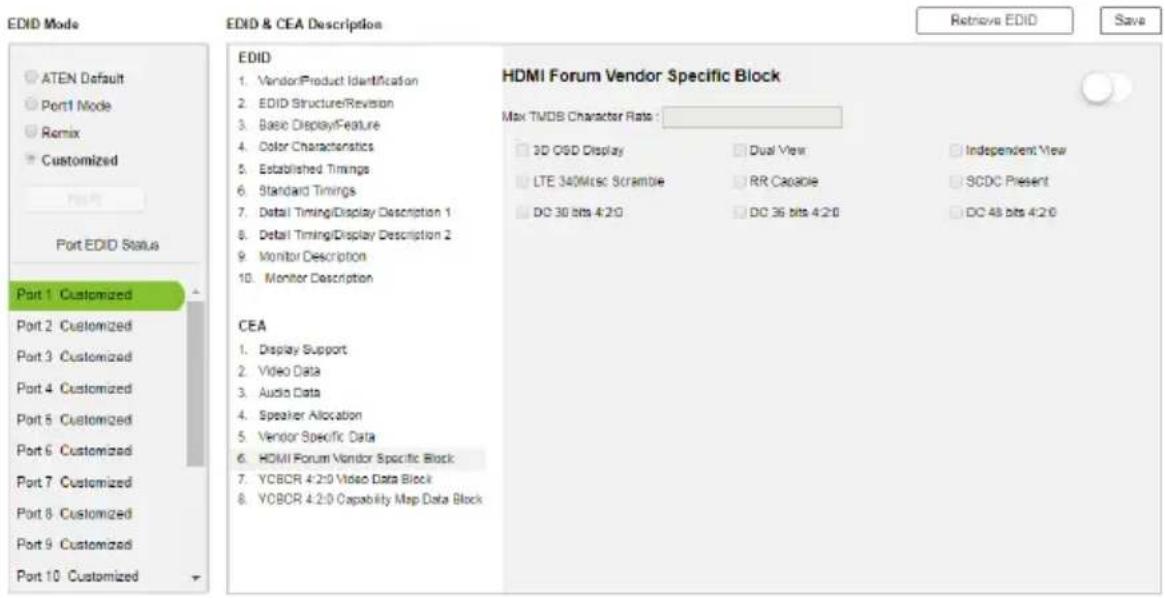
text_image
EDID Mode ATEN Default Port1 Mode Remix Customized Port EDID Status Port 1 Customized Port 2 Customized Port 3 Customized Port 4 Customized Port 5 Customized Port 6 Customized Port 7 Customized Port 8 Customized Port 9 Customized Port 10 Customized EDID 1. Vendor/Product Identification 2. EDID Structure/Revision 3. Basic Display/Feature 4. Color Characteristics 5. Established Timings 6. Standard Timings 7. Detail Timing/Display Description 1 8. Detail Timing/Display Description 2 9. Monitor Description 10. Monitor Description CEA 1. Display Support 2. Video Data 3. Audio Data 4. Speaker Allocation 5. Vendor Specific Data 6. HDMI Forum Vendor Specific Block 7. YCBCR 4:2:0 Video Data Block 8. YCBCR 4:2:0 Capability Map Data Block HDMI Forum Vendor Specific Block Max TMDB Character Rate : 3D OSD Display Dual View Independent View LTE 340MHz Scramble RR Capable SCDC Present DC 30 bits 4:2:0 DC 36 bits 4:2:0 DC 48 bits 4:2:0- 3D OSD Disparity: Select this option to have Sink support receiving 3D OSD Disparity Indication in the HF-VSIF.
Dual View: Select this option to have Sink support receiving 3D Dual View in the HF-VSIF. - Independent View: Select this option to have Sink support receiving 3D Independent View in the HF-VSIF.
- LTE 340Mcsc Scramble: Select this option to have Sink support scrambling for TMDS Character Rates at or below 340 Mcsc.
- RR Capable: Select this option to have Sink initiate an SCDC Read Request.
- SCDC Present: Select this option to have Sink support SCDC functionality.
- DC 30bit 420: Select this option to have Sink support 10-bits/component Deep Color 4:2:0 Pixel Encoding.
- DC 36bit 420: Select this option to have Sink support 12-bits/component Deep Color 4:2:0 Pixel Encoding.
- DC 48bit 420: Select this option to have Sink support 16-bits/component Deep Color 4:2:0 Pixel Encoding.
Use the drop down menu to select the Audio Format (1\~6) applicable to your audio output device, and click Save to apply the changes.
YCBCR 4:2:0 Video Data Block
Use this page to configure a list of supported YCBCR 4:2:0 video resolutions and select one to be applied. Use the toggle button at the top-right to enable or disable this feature.
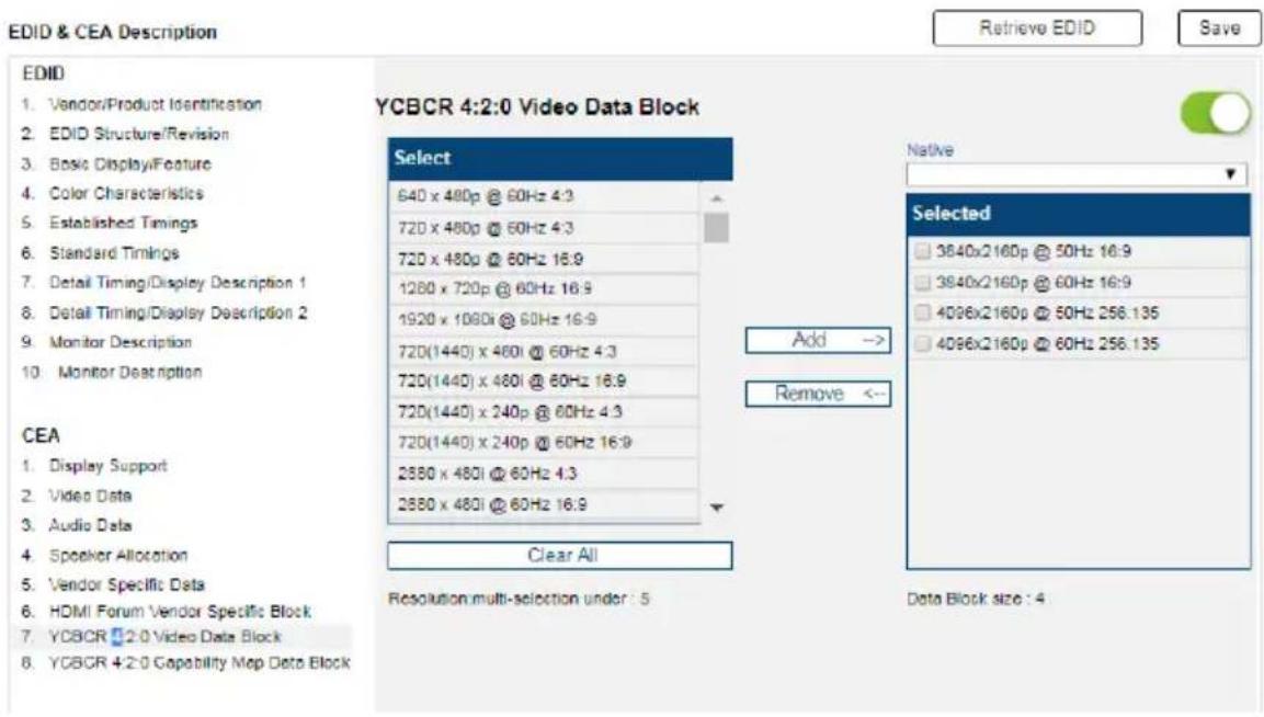
text_image
EDID & CEA Description Retrieve EDID Save EDID 1. Vendor/Product Identification 2. EDID Structure/Revision 3. Basic Display/Feature 4. Color Characteristics 5. Established Timings 6. Standard Timings 7. Detail Timing/Display Description 1 8. Detail Timing/Display Description 2 9. Monitor Description 10. Monitor Description YCBCR 4:2:0 Video Data Block Select 640 x 480p @ 60Hz 4:3 720 x 480p @ 60Hz 4:3 720 x 480p @ 60Hz 16:9 1280 x 720p @ 60Hz 16:9 1920 x 1080i @ 60Hz 16:9 720(1440) x 480i @ 60Hz 4:3 720(1440) x 480i @ 60Hz 16:9 720(1440) x 240p @ 60Hz 4:3 720(1440) x 240p @ 60Hz 16:9 2880 x 480i @ 60Hz 4:3 2880 x 480i @ 60Hz 16:9 Add → Remove <- Selected 3840x2160p @ 50Hz 16:9 3840x2160p @ 60Hz 16:9 4D96x2160p @ 50Hz 256.135 4D96x2160p @ 60Hz 256.135 CEA 1. Display Support 2. Video Data 3. Audio Data 4. Speaker Allocation 5. Vendor Specific Data 6. HDMI Forum Vendor Specific Block 7. YCBCR 4:2:0 Video Data Block 8. YCBCR 4:2:0 Capability Map Data Block Clear All Resolution multi-selection under : 5 Data Block size : 4- To add a supported resolution, click an item in the Select column, and then click Add.
- Use the drop down menu Native to adjust the supported resolution of the display.
YCBCR 4:2:0 Compatibility Map Data Block
Use this page to configure a list of supported video resolutions for YCBCR 4:2:0 Compatibility Map Data Block and select one to be applied. Use the toggle button at the top-right to enable or disable this feature.
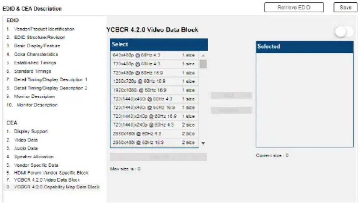
text_image
EDID & CEA Description Retrieve EDID Save EDID 1. Vendor/Product Identification 2. EDID Structure/Revision 3. Basic Display/Feature 4. Color Characteristics 5. Established Timings 6. Standard Timings 7. Detail Timing/Display Description 1 8. Detail Timing/Display Description 2 9. Monitor Description 10. Monitor Description YCBCR 4:2:0 Video Data Block Select 640x480p @ 60Hz 4.3 1 size 720x480p @ 60Hz 4.3 1 size 720x480p @ 60Hz 16.9 1 size 1280x720p @ 60Hz 16.9 1 size 1920x1080i @ 60Hz 16.9 1 size 720(1440)x480i @ 60Hz 4.3 1 size 720(1440)x480i @ 60Hz 16.9 1 size 720(1440)x240p @ 60Hz 16.9 1 size 720(1440)x240p @ 60Hz 4.3 2 size 2880x480i @ 60Hz 4.3 2 size 2880x480i @ 60Hz 16.9 2 size CEA 1. Display Support 2. Video Data 3. Audio Data 4. Speaker Allocation 5. Vendor Specific Data 6. HDMI Forum Vendor Specific Block 7. YCBCR 4:2:0 Video Data Block 8. YCBCR 4:2:0 Capability Map Data Block Max size is : 0 Selected Current size : 0- To add a supported resolution, click an item in the Select column, and then click Add.
- Use the drop down menu Native to adjust the supported resolution of the display.
Status
Connections
The connections tab provides a status summary of the input/output boards installed to the VM1600A and the devices that are connected to the ports on the input/output boards. If the connected devices support FrameSync and Long Reach mode, you can also enable/disable the function on this page.
Connections
| Device List | Model Name | FW Version | Temperature | Power Consumption | HDCP | Cable Quality | FrameSync | Long Reach Mode |
| Main Board - VM@2F | VM3200 | v0.00.000 | 43°C | 50W(Max) | - | |||
| Input Slot 1 | VM8814 | v0.00.000 | 43°C | 50W(Max) | - | |||
| Port 1 | Cable Quality Test | OFF | ||||||
| Transmitter | VE801T | v0.00.000 | - | - | - | |||
| MacBook | ModelName | - | - | - | - | |||
| Port 2 | Cable Quality Test | OFF | ||||||
| Port 3 | Cable Quality Test | OFF | ||||||
| Port 4 | Cable Quality Test | OFF | ||||||
| MacBook | ModelName | - | - | - | - | |||
| Output Slot 1 | VM8814 | v0.00.000 | 43°C | 50W(Max) | - | |||
| Port 1 | Cable Quality Test | OFF | OFF | |||||
| Port 2 | Cable Quality Test | OFF | OFF | |||||
| Port 3 | Cable Quality Test | OFF | OFF | |||||
| Port 4 | Cable Quality Test | OFF | OFF |
Use the Connections page to:
◆ Monitor input/output board temperatures.
◆ Find out about HDCP settings of the input/output boards
◆ Perform cable quality analysis by clicking the Cable Quality Test button.
Note:
♦ BER Test is only applicable to the following cable connections:
- VM7814 with its source device
VE816R with VM8514
- To test the quality of the cable connecting the VM7814 input board and its source device, unplug the cable from the source device and plug it into the corresponding port on the VM8814 output board, and then click the BER Test button to start the test. For example, if a cable plugs into port 1 of a VM7814 board, the other end should be plugged into port 1 of the VM8814 board before you start the test.
- To test the quality of all the cables connected to the Modular Matrix Switch, click BER Test at the top-right corner of the page.
◆ Enable/disable FrameSync and/or Long Reach Mode
System Information
Use this page to look up system settings, including system network settings, firmware version, video/audio input assignments, output audio volumes, CED/OSD settings, output resolutions, HDMI audio mode settings, and power statuses.
Hint: Click to view details and to refresh the system.
System Info
| System Network | |
| IP Address | 10.3.52.124 |
| Sub Mask | 255.255.254.0 |
| Gateway | 10.3.53.254 |
| MAC Address | DD:10.74.AE.01.22 |
| IP Assign | Static IP |
| Mainboard Info | |
| Video Connection | |
| Audio Connection | |
| Volume | |
| CEC | |
| OSD | |
| Output Resolution | |
| HDMI Audio Mode | |
| Plug Status | |
Channel
IR/RS-232
The IR/RS-232 page is used to configure the IR/RS-232 communication routes between the input and output ports.
Note: The IR/RS-232 pages are only supported by VM7514/VM7584 and VM8514/VM8584 boards.
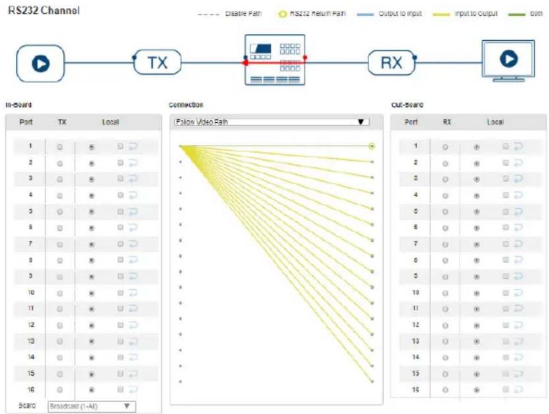
flowchart
graph LR
    A["Input"] --> B["TX Channel"]
    B --> C["RX Channel"]
    C --> D["Output"]
    subgraph In-Board
        E["Port 1"] --> F["TX 1"]
        G["Port 2"] --> H["TX 2"]
        I["Port 3"] --> J["TX 3"]
        K["Port 4"] --> L["TX 4"]
        M["Port 5"] --> N["TX 5"]
        O["Port 6"] --> P["TX 6"]
        Q["Port 7"] --> R["TX 7"]
        S["Port 8"] --> T["TX 8"]
        U["Port 9"] --> V["TX 9"]
        W["Port 10"] --> X["TX 10"]
        Y["Port 11"] --> Z["TX 11"]
        AA["Port 12"] --> AB["TX 12"]
        AC["Port 13"] --> AD["TX 13"]
        AE["Port 14"] --> AF["TX 14"]
        AG["Port 15"] --> AH["TX 15"]
        AI["Port 16"] --> AJ["TX 16"]
        AK["Board Broadcast (1-AI)"] --> AL["Backward Arrow to Panel"]
    end

    subgraph Out-Board
        AM["Port 1"] --> AN["TX 1"]
        AO["Port 2"] --> AP["TX 2"]
        AQ["Port 3"] --> AR["TX 3"]
        AS["Port 4"] --> AT["TX 4"]
        AU["Port 5"] --> AV["TX 5"]
        AW["Port 6"] --> AX["TX 6"]
        AY["Port 7"] --> AZ["TX 7"]
        BA["Port 8"] --> BB["TX 8"]
        BC["Port 9"] --> BD["TX 9"]
        BE["Port 10"] --> BF["TX 10"]
        BG["Port 11"] --> BH["TX 11"]
        BI["Port 12"] --> BJ["TX 12"]
        BK["Port 13"] --> BL["TX 13"]
        BM["Port 14"] --> BN["TX 14"]
        BO["Port 15"] --> BP["TX 15"]
        BQ["Port 16"] --> BR["TX 16"]
        BS["Backward Arrow to Panel"]
    end

    style In-Board fill:#f9f,stroke:#333
    style Out-Board fill:#bbf,stroke:#333
RS232 Command-line

text_image
HEX Submit- In-Board: Use this set of settings to configure the IR/RS-232 signals for each input port.
- Port 1 \~ Port 16: Configure each input port to use the Local IR/RS-232, Tx IR/RS-232, or Loopback for IR/RS-232 signals.
-
Board:
-
Broadcast (1-All): Controls all the connected devices simultaneously.
- Manual: Controls specified devices simultaneously. Click Edit to select devices.
Use Loopback for the IR/RS-232 signals to be sent back to local source or local display device connected to the same port on the same I/O board. This allows you to use the IR/RS-232 connection to control devices locally. Loopback prevents the IR/RS-232 signals from being sent across the connection to another I/O board. The Loopback setting is useful when you use a VM8514/VM8584 board to extend displays but use a different board type (not VM7514) for input devices and want to use the IR/RS-232 signals for local control.
- RS-232 Command Line: Use this setting to remotely control a connected device via RS-232 commands.
- Connection: Sets the connection path for the IR/RS-232 signals.
- Use the drop-down menu to select Follow Video Path to have the IR/RS-232 signal use the same connection path as the profile settings.
- Use the drop-down menu to select Broadcast (1-All) to broadcast the IR/RS-232 signal from one port to all ports. Use the drop-down menu that appears to select the port that broadcasts the IR/RS-232 signal.
- Out-Board: Use this set of settings to configure the IR/RS-232 signals for each output port.
- Port 1 \~ Port 16: Configure each output port to use the Local IR/RS-232, Rx IR/RS-232, or Loopback setting for the IR/RS-232 signals.
Note: By default the RS-232 Return Path uses the lowest port number available for a connection. This setting can not be changed.
Maintenance
System Setup
You can use the System Setup page to do any of the following:
- Upgrade the VM1600A's mainboard, its streaming board, and any installed I/O boards
- Back up or restore the VM1600A's settings. Note that account settings cannot be backed up or restored.
Firmware upgrade
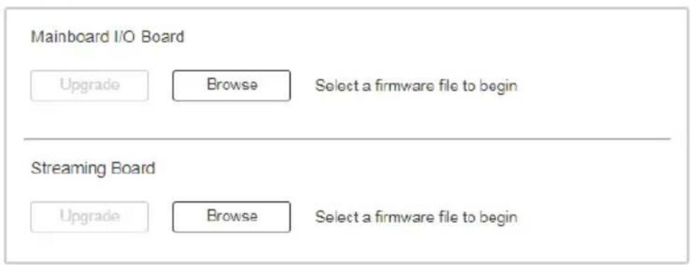
text_image
Mainboard I/O Board Upgrade Browse Select a firmware file to begin Streaming Board Upgrade Browse Select a firmware file to beginBackup / Restore
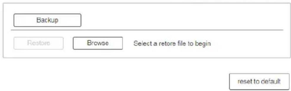
text_image
Backup Restore Browse Select a restore file to begin reset to defaultTo upgrade the VM1600A's firmware, do the following:
- Download the firmware package from ATEN's official website.
- In the VM1600A web interface, go to Maintenance > System Setup > Firmware Upgrade > Mainboard I/O Board, click Browse to locate the firmware upgrade package.
- Click Upgrade to begin the upgrade.
Note: After updating the firmware, it's recommended that you clear your web browser's cache and then close and reopen the web browser. This will ensure the GUI refreshes and functions properly.
To upgrade the VM1600A's streaming board, do the following:
- Download the firmware package from ATEN's official website. Select the one that indicates “streaming board” in the file name.
- In the VM1600A web interface, go to Maintenance > System Setup > Firmware Upgrade > Streaming Board, click Browse to locate the firmware upgrade package.
- Click Upgrade to begin the upgrade.
To back up the VM1600A's system settings, click Backup. A configuration file will then begin downloading.
To restore the VM1600A's system settings, do the following:
- Use the Browse button to locate the configuration file. Make sure you have the correct file saved on your PC.
- Click Restore to begin the restoration procedure.
Note: User accounts cannot be backed up or restored.
To reset the VM1600A to its default settings, click the reset to default button on the far right.
User Account
The User Account page lets you add, edit, or delete users and change the password for accessing the VM1600A's GUI.
Note: This is an Administrator only function.

text_image
User Name Level Description administrator Administrator Default_User user_1 Basic User User_Account + Add account Edit- Add account – Click the Add account button to add another user to the list. The VM1600A supports up to 32 users and up to 16 concurrent logins (see page 124 for more details).
- Edit – Click the Edit button to change user information. This option allows an Administrator to edit individual accounts.
| User Name | Level | Description |
| Edit 111111 | Administrator | 111111 |
| Edit 12345 | Administrator | |
| Edit administrator | Administrator | Default_user |
- Edit – Rename the user account, set the password, add a description, and set the user’s permission level (see page 126 for more details).
- Delete – Removes the user account.

- The default username and password are: administrator/password.
Add Account
Use the Add Account / Edit buttons to create a user account, set the user's password, add a description, and set the user's permission level (see , page 125) when accessing the VM1600A's GUI.
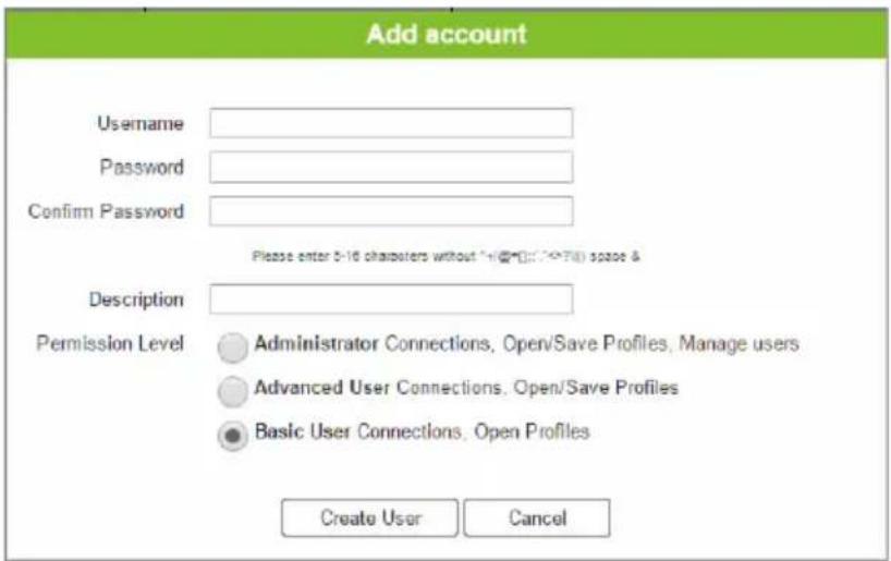
text_image
Add account Username Password Confirm Password Please enter 5-16 characters without "+(@:)": <> (if) space & Description Permission Level Administrator Connections, Open/Save Profiles, Manage users Advanced User Connections, Open/Save Profiles Basic User Connections, Open Profiles Create User Cancel◆ Fill in a username or edit an existing one.
- Enter a password and re-type the password to confirm.
Note: Usernames and passwords accept multi-lingual characters, and must be 5–16 alphanumeric characters (excluding :;=[]+=/?|). Passwords are case sensitive. Usernames only support lower case letters.
- Add or edit the description for the user.
- Select the permission level that you want to grant the user (see, page 125).
- Click Create User to save the data.
- Click Cancel to discard the changes and exit.
If a user is logged into the VM1600A's GUI, their user settings cannot be edited, and the fields in this screen are grayed out.
Permission Level
At the bottom of the New/Edit User page is the permission section, which is used to set a user's permission level.
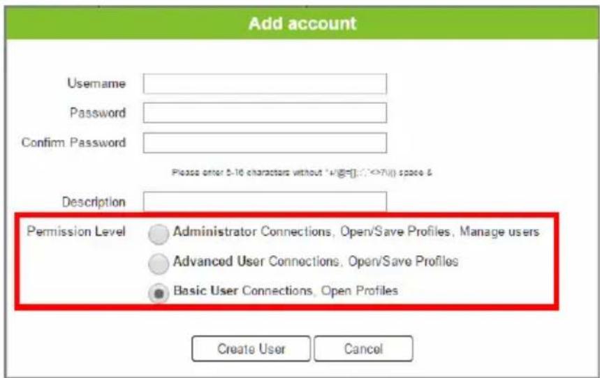
text_image
Add account Username Password Confirm Password Please enter 5-10 characters without "U(G=):">70() space & Description Permission Level Administrator Connections, Open/Save Profiles, Manage users Advanced User Connections, Open/Save Profiles Basic User Connections, Open Profiles Create User CancelThe three available permission levels are as follows:
- Administrator – this level provides full access and control of the VM1600A, in addition to full User Management privileges.
- Advanced User – this level provides full access and control with no User Management privileges.
- Basic User – this level only provides basic functions (connections and open profiles).
Network
The Network page lets you configure the VM1600A's IP settings for connecting to it via the web GUI, and enable/disable Telnet.
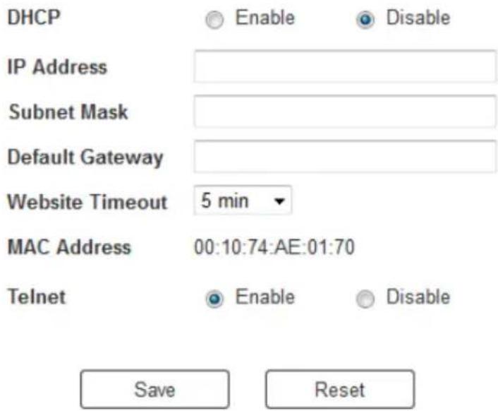
text_image
DHCP Enable Disable IP Address Subnet Mask Default Gateway Website Timeout 5 min MAC Address 00:10:74:AE:01:70 Telnet Enable Disable Save ResetEnable DHCP to allow the DHCP server to assign an IP address to the VM1600A. Select Disable to enter your own static IP address settings for the device.
Click Reset to use the following default values:
IP Address - 192.168.0.60
Subnet Mask - 255.255.255.0
♦ Default Gateway – 192.168.0.1
Website Timeout* – N/A, 5, 10, 30, 60 minutes
♦ Telnet Configuration enabled (checked)
Enter the values, then click Save. Changes may take a few seconds and after refreshing the page automatically redirects you to the IP address specified.
* This option controls how long an inactive web connection stays logged into the VM1600A. Any changes will take effect immediately. The default setting is 5 minutes.
This Page Intentionally Left Blank
Overview
The VM1600A supports Video Matrix Control App, a free mobile app that allows you to switch profiles, audio inputs and video inputs, and also reminds you when any new firmware is available, all through a local area network to which the target VM1600A is connected. This mobile application is especially useful for profile and AV source switching when you do not have access to the VM1600A's front panel or the web interface.
The Video Matrix Control App
Requirements
- The Video Matrix Control App supports the following operating systems:
| Mobile Operating System Supported Versions | |
| iOS 10.2.1 or later | |
| Android 7.0 or later | |
- The VM1600A needs to be connected to a local area network via the Ethernet port.
Installation and Connections
To install the Video Matrix Control App on a mobile device, do the following:
- From the mobile device, tap the App Store 🎨 or Google Play 🎯 icon.
- In the search box, type "Video Matrix Control App".
- Tap Video Matrix Control App and then download and install the app.
- Tap the app icon.
- Follow the on-screen instructions to connect to the target VM1600A device by scanning the network, selecting from connection history, or specifying the device IP address and password.
Note:
- The Video Matrix Control App is designed to control one VM1600A device at a time.
- If you cannot find the VM1600A device, make sure that the VM1600A is connected to LAN and that the app is connected to the same LAN and then try again.
The Control Interface
The functions in the Video Matrix Control App are categorized into four tabs – Profile, Control, Audio, and Settings. See the table below for an overview of each tab.
Control Interface Description
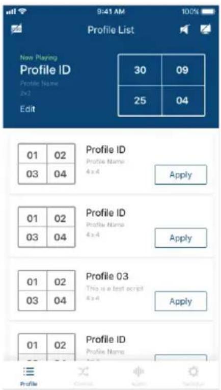
text_image
New Playing Profile ID Profile Name 2x2 Edit 30 09 25 04 Profile ID Profile Name 4 x 4 Apply Profile ID Profile Name 4 x 4 Apply Profile ID Profile Name 4 x 4 Apply Profile ID This is a text script 4 x 4 Apply Profile ID Profile Name 4 x 4 ApplyIn the Profile tab, you can switch profiles for display or change the video input for the profile that is playing.
Note:
The Video Matrix Control App can not be used to create profiles. Before using the app, make sure to create the profiles you need via the web interface. For details, see Creating a Profile, page 71.
◆ Any configuration change made to a profile via Video Matrix Control App is only effective while the profile is being played and will not be saved to the VM1600A unit.
◆ Previews of input assignment, as indicated by input numbers in the control interface on the left, are not supported for VM0404HB, VM0808HA, and VM0808HB.
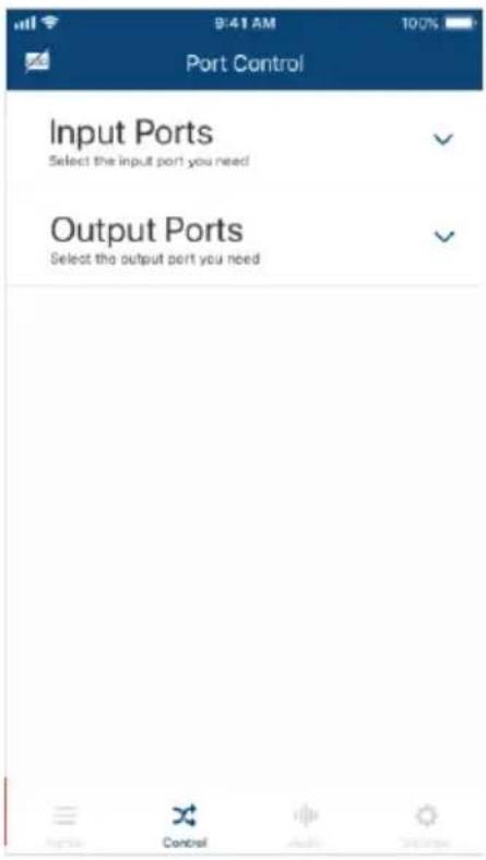
text_image
9:41 AM Port Control Input Ports Select the input port you need Output Ports Select the output port you needIn the Control tab, you can instantly switch video inputs for each of the output.
Control Interface Description
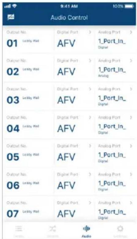
text_image
9:41 AM Audio Control Output No. 01 Lobby Wall Digital Port > AFV Analog Port > 1_Port_In_ Digital Output No. 02 Lobby Wall Digital Port > AFV Analog Port > 1_Port_In_ Analog Output No. 03 Lobby Wall Digital Port > AFV Analog Port > 1_Port_In_ Digital Output No. 04 Lobby Wall Digital Port > AFV Analog Port > 1_Port_In_ Digital Output No. 05 Lobby Wall Digital Port > AFV Analog Port > 1_Port_In_ Digital Output No. 06 Lobby Wall Digital Port > AFV Analog Port > 1_Port_In_ Digital Output No. 07 Lobby Wall Digital Port > AFV Analog Port > 1_Port_In_ DigitalIn the Audio tab, you can specify the audio input for the digital and analog outputs of the VM1600A.
Note: The fields available in this tab may vary for the connected device.
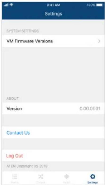
text_image
Settings SYSTEM SETTINGS VM Firmware Versions > ABOUT Version 0.00.0001 Contact Us Log Out ATEN Copyright (c) 2019In the Settings tab, you can look up notification for system firmware upgrades, the current app version, and technical support contact, or log out of the app.
Overview
The VM1600A can be configured and controlled via RS-232 or Telnet commands when connected to a host computer or other device, such as a control system. This chapter provides information on how to connect to the VM1600A via RS-232/Telnet and command syntax.
Connecting to the Matrix Switch via Telnet
To establish a Telnet session with the VM1600A, do the following:
- Connect a host computer or control system to a shared network with the VM1600A.
- Open a command-line interpreter program from your computer.
- In the command-line interpreter, type the VM1600A's IP address in the following way:
telnet [IP address]:23
-
Press Enter. The login screen appears.
-
At the login prompt, type the login username and password for the VM1600A.
-
When a session is established with the VM1600A, you can control and configure the VM1600A via RS-232 commands. For more information on commands, see Commands, page 136
Note: If a user logs in using a username that is already in session, the newest login takes effect and the previous session will be replaced.
Connecting to the Matrix Switch via RS-232
RS-232 serial operations in a VM1600A installation can be managed via a Graphical User Interface (GUI) on systems that are running Windows. In order to use this Control Tool, two separate items of software must be installed on all of the PCs in your installation – .NET Framework 2.0 and the Control Tool AP. Please download the VM1600A RS-232 Control Tool AP and user instructions from the ATEN website (www.aten.com).
Note: For Windows 7 64-bit systems, the following must be installed first:
1) Microsoft Office 64-bit Access Database software; and
2) Microsoft 64-bit ODBC and OLEDB driver.
To connect to the VM1600A via RS-232, do the following:
- Connect the RS-232 serial port on the VM1600A to the RS-232 serial port on your computer using a 9-wire straight cable, with only pin 2 to pin 2, pin 3 to pin 3, and pin 5 to pin 5 connected.
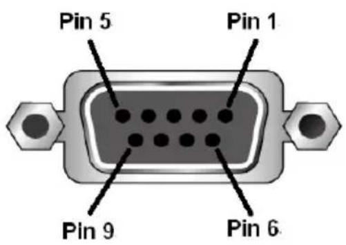
text_image
Pin 5 Pin 1 Pin 9 Pin 6| Pin Description | |
| 1 Not connected | |
| 2 | RXD |
| 3 | TXD |
| 4 Not connected | |
| 5 | GND |
| 6 Not connected | |
| 7 Not connected | |
| 8 Not connected | |
| 9 Not connected | |
- The controller's serial port should be configured as follows:
| RS-232 Protocol | |
| Baud Rate 19200 | |
| Data Bits 8 | |
| Parity None | |
| Stop Bits 1 | |
| Flow Control None | |
- When a session is established with the VM1600A, you can control and configure the VM1600A via RS-232 commands. For more information on commands, see Commands, page 136.
Verification
After entering a command, a verification message appears at the end of the command line as follows:
- Command OK - indicates that the command is correct and successfully performed by the switch
- Command incorrect - indicates that the command has the wrong format and/or values.
Commands
After connecting to the VM1600A via Telnet or RS-232, you can operate the system using the following commands.
Switch Port Command
The formula for Switch commands is as follows:
$$ \begin{array}{l} \text {Switch Command + Input + Num1 + Output + Num2 + Address +} \ \text {Num3 + Stream + Control [Enter]} \end{array} $$
- For example, to switch input port 02 to output port 05, type the following:
$$ \text { sw i02 o05 [Enter] } $$
- To switch output port 04 to the next port, input the following:
$$ \mathbf {s w} \quad \mathbf {o 0 4} + [ \text { Enter } ] $$
- To turn off video output on port 03, type the following:
$$ \text { sw o03 off [Enter] } $$
- To turn off video output on port 03 on device 02, type the following:
$$ \text { sw o03 a02 off [Enter] } $$
The following tables show the possible values for the Switch Port command
| Command Description | |
| sw Switch command | |
| Input Description | |
| i Input port command | |
| Num1 Description | |
| xx Input port | xx: 01~16 |
| * All input ports | |
| Output Description | |
| o Output port command | |
| Num2 Description | |
| yy Output port | yy: 01~16 |
| Num2 Description | |
| * All output ports | |
| Address Description | |
| a Device address command(RS-422 and RS-485 only) | |
| Num3 Description | |
| zz Device addresszz: 01~16 (default is 01)(RS-422 and RS-485 only) | |
| * All devices | |
| Stream Description | |
| Video Switch | Video Channel Only |
| Audio Switch | Stereo Audio Channel Only |
| All Switch | Video Channel and Stereo Audio Channel Default Select if been omitted |
| Control Description | ||
| on Turn on | the display | |
| off Turn off | the display | |
| + | N | e x |
| - Previous | Port | |
Note: By default, input port 01 is tied to output port 01; input port 02 is tied to output port 02; and so on until port 08 (i.e., o01 i01, o02 i02... o16 i16)
The following table shows the available command list:
| Command | Input | Input Port | Output | Output Port | Address | Device No. | Stream | Control | Enter Description |
| sw i xx | * | o | yy * | a | zz * | video audio all | [Enter] Switch Input Port xx to Output Port yy on address zz xx:01~16, * yy:01~16, * zz: 01~16, * | ||
| sw o yy | * | a | zz * | video audio all | on off | [Enter] Turn on Output Port yy Turn off Output Port yy on address zz yy:01~16, * zz: 01~16, * | |||
| sw o yy | * | a | zz * | video audio all | + - | [Enter] Switch Next Input to Output Port yy Switch Previous Input to Output Port yy yy:01~16, * |
Note: 1. Each command string can be separated with a space.
2. The Address command is for RS-422/485 only. If the address parameter is missing from RS-422/485 commands, the default a00 will be used. Skip the address for RS-232 commands.
3. The Port Number and Address command strings can be skipped, and the default value will be used.
Mute Command
Mute allows you to enable or disable an output port's audio. The Mute command will turn on/off the HDMI audio and stereo audio. When the HDMI audio is off, the stereo's volume can be adjusted using the volume command.
The formula for the Mute command is as follows:
$$ \text { Command } + \text { Output } + \text { Num1 } + \text { Address } + \text { Num2 } + \text { Control } + [ \text { Enter } ] $$
-
For example, to mute the audio on output port 03, type the following: mute o03 on [Enter]
-
To turn mute off on all output ports, type the following:
$$ \text { mute } \mathbf {o} ^ {*} \text { off } [ \text { Enter } ] $$
- To mute the audio for output port 09 on device 03, type the following: mute o09 a03 on [Enter]
The following tables show the possible values for the Mute command:
| Command Description | |
| mute Mute command | |
| Output Description | |
| o Output port command | |
| Num1 Description | |
| xx Output port numberxx: 01~16 (default is 01) | |
| * All output ports | |
| Address Description | |
| a Device address command(RS-422 and RS-485 only) | |
| Num2 Description | |
| zz Device addresszz: 01~16 (default is 01)(RS-422 and RS-485 only) | |
| * All devices | |
| Control Description | |
| on Mute on; audio on output port is disabled | |
| Control Description | |
| off Mute off; audio on output port is enabled (default) |
Note: 1. Each command string can be separated with a space.
-
The Address command is for RS-422/485 only. If the address parameter is missing from RS-422/485 commands, the default a00 will be used. Skip the address for RS-232 commands.
-
Skip the Output command to mute or enable the audio of all output ports.
The following table shows the available command list:
| Command | Output Num1 | Address | Num2 | Control | Enter Description |
| mute o xx | * | a | zz* | on [Enter] Mute | |
| mute o xx | * | a | zz* | off [Enter] Turn | |
Volume Command
The volume command adjusts the stereo volume for an output port.
The formula for the Volume command is as follows:
$$ \begin{array}{l} \text {Command + Output + Num1 + Address + Num2 + Volume + Control} \ + [ \text {Enter} ] \end{array} $$
- For example, to adjust the volume for output port 06 to level 5, type the following:
$$ \text { volume o06 v05 [Enter] } $$
- To adjust the volume for all output ports to level 04, type the following:
$$ \text { volume } \mathbf {o} ^ {*} \mathbf {v 0 4} [ \text { Enter } ] $$
- For example, to adjust the volume for output port 06 on device 01 to level 10, type the following:
$$ \text { volume o06 a01 v10 [Enter] } $$
The following tables show the possible values for the Volume command:
| Command Description | |
| volume Volume command | |
| Output Description | |
| o Output port command | |
| Num1 Description | |
| xx Output port | xx: 01~16 (default is 01) |
| * All output ports | |
| Address Description | |
| a Device address command(RS-422 and RS-485 only) | |
| Num2 Description | |
| yy Device address | yy: 01~16 (default is 01)(RS-422 and RS-485 only) |
| * All devices | |
| Volume Description | |
| v Volume level command | |
| Control Description | |
| zz Audio volume level | zz: 01~10 (default is 10) |
Note: 1. Each command string can be separated with a space.
- The Address command is for RS-422/485 only. If the address parameter is missing from RS-422/485 commands, the default a00 will be used. Skip the address for RS-232 commands.
The following table shows the available command list:
| Command | Output | Num1 | Address | Num2 | Volume | Control | Enter Description |
| volume o | xx | * | a | yy* | v | zz [Enter] Adjust | |
| volume for output port xx, on device yy, to level zz xx:01~16,* yy: 01~16,* zz: 01~10,* | |||||||
Save/Load Profile Commands
The Save/Load Profile command allows you to save the current connection configuration as a profile and load connection profiles.
The formula for Save/Load Profile commands is as follows:
$$ \text { Command } + \text { Profile } + \text { Num1 } + \text { Address } + \text { Num2 } + \text { Control } + [ \text { Enter } ] $$
- For example, to save the current connection configuration as profile 08, type the following:
$$ \text { profile f08 save [Enter] } $$
- To load connection profile 04, type the following:
$$ \text { profile f04 load [Enter] } $$
- To save the current connection configuration of device 03 as profile 08, type the following:
$$ \text { profile f08 a03 save [Enter] } $$
The following tables show the possible values for commands:
| Command Description | |
| profile Save | / Load Profile command |
| Profile Description | |
| f Profile | command |
| Num1 Description | |
| xx Profile | numberxx: 01-32 (default is 01) |
| Address Description | |
| a Device | address command(RS-422 and RS-485 only) |
| Num2 Description | |
| yy Device | addressyy: 01~16 (default is 01)(RS-422 and RS-485 only) |
| * All devices | |
| Control Description | |
| save Save | the current connection configuration |
| Control | Description |
| load Load | a saved profile |
Note: 1. Each command string can be separated with a space.
-
The Address command is for RS-422/485 only. If the address parameter is missing from RS-422/485 commands, the default a00 will be used. Skip the address for RS-232 commands.
-
If the Address or Profile parameter is skipped the default value will be used.
The following table shows the available command list:
| Command | Profile Num1 Address | Num2 | Control | Enter Description | ||
| profile f xx a yy | * | save [Enter] Save current connection configuration on device yy as profile xxxx:01~16yy: 01~16,* | ||||
| profile f xx a yy | * | load [Enter] Load | profile xx on device yyxx:01~16yy: 01~16,* | |||
EDID Mode Command
Extended Display Identification Data (EDID) is data that contains a display's basic information and is used to communicate with the video source. The EDID Mode commands allow you to change the EDID setting.
The formula for the EDID command is as follows:
$$ \text { Command } + \text { Address } + \text { Number } + \text { Control } + [ \text { Enter } ] $$
- For example, for port 06 to use the remix EDID mode, type: edid a06 remix [Enter]
- For example, to use Port1 EDID mode for all devices, type:
- edid a* port1 [Enter]
The following tables show the possible values for the EDID command:
| Command Description | |
| edid EDID command | |
| Address Description | |
| a Device address command(RS-422 and RS-485 only) | |
| Number Description | |
| zz Device addresszz: 01~16 (default is 01)(RS-422 and RS-485 only) | |
| * All devices | |
| Control Description | |
| port1 Implement the EDID of the connected display to Port 1, and pass it to the video source. | |
| remix Implement the EDID of each connected display according to its connection when the VM1600A is first powered on, or immediately after selecting the Remix option. | |
| default Implements ATEN's default EDID.(default) | |
| custom Implements the customized mode as set in the EDID system settings.(See Customized Mode, page 108) | |
Note: 1. Each command string can be separated with a space.
- The Address command is for RS-422/485 only. If the address parameter is missing from RS-422/485 commands, the default a00 will be used. Skip the address for RS-232 commands.
The following table lists the available EDID commands:
| Command | Address | Num | Control | Enter | Description |
| edid a zz | * | port1 [Enter] The | EDID from Port 1 is passed to the video source. zz: 01~16 | ||
| edid a zz | * | remix [Enter] The | VM1600A implements the EDID of each connected display according to its connection when the device is first powered on, or immediately after selecting the Remix option. | ||
| edid a zz | * | default [Enter] AT | TEN's default EDID is passed to the video source. | ||
| edid a zz | * | custom [Enter] Im | plements the customized mode. | ||
CEC Command
Consumer Electronics Control (CEC) allows interconnected HDMI devices to communicate with and respond to the same remote control.
The formula for the CEC command is as follows:
$$ \text { Command } + \text { Output } + \text { Number } + \text { Control } + [ \text { Enter } ] $$
- For example, to enable the CEC function on output port 1, type:
cec o01 on [Enter]
The following tables show the possible values for the CEC command:
| Command Description | |
| cec CEC command | |
| Output Command Description | |
| o Output port command | |
| Number Description | |
| yy Output port01~16 port (default is 01) | |
| * All output ports | |
| Control Description | |
| off Disable CEC (default) | |
| on Enable CEC |
Note: Each command string can be separated with a space.
The following table lists the available CEC commands:
| Command | Output Port | Control Enter Description | |
| cec | yy* | off [Enter] | CEC off for output port yy (default)(yy:01~16, *) |
| cec | yy* | on [Enter] | CEC on for output port yy(yy:01~16, *) |
Read Command
The Read command allows you to view information about the devices.
The formula for the Read command is as follows:
$$ \text { Command } + \text { Address } + \text { Number } + [ \text { Enter } ] $$
- To view information, type:
read [Enter]
- To view information about device 02, type:
read a02 [Enter]
The following table shows the possible values for the Read command:
| Command Description | |
| read Read command | |
| Address Description | |
| a Device address command(RS-422 and RS-485 only) | |
| Number Description | |
| zz Device addresszz: 01~16 (default is 01)(RS-422 and RS-485 only) | |
| * All Devices | |
Note: The Address command is for RS-422/485 only. If the address parameter is missing from RS-422/485 commands, the default a00 will be used. Skip the address for RS-232 commands.
The following table lists the available Read commands:
| Command | Address | Num | Enter | Description |
| read a | zz | * | [Enter] | View information about device number zz: 01~16 |
DVI/HDMI Example:
read Command OK
o01 i03 video on i06 audio v10 HDMI-A on 1080p
o02 i04 video off i06 audio off HDMI-A off bypass
o03 i02 video on i06 audio v10 HDMI-A off 1600
How to read the commands:
- o01 i03 video on i06 audio v10 HDMI-a on 1080p
Output 01 is connected to Input 03 with video on; audio is on from Input 06 with volume 10 using the HDMI audio source; the resolution is scaled to 1080p
- o01 i03 video on i06 audio v10 1080p
Output 01 is connected to Input 03 with video on; audio is on with volume 10; the resolution is scaled to 1080p
- o02 i04 video off i06 audio off HDMI-a off bypass
Output 02 is connected to Input 04 with video off; audio is off from Input 06 using the HDMI audio source; scaling is bypassed (turned off)
Reset Command
The Reset command allows you to reset the VM1600A back to the default factory settings. Reset includes resetting the device's IP address.
The formula for the Reset command is as follows:
$$ \text { Command } + \text { Address } + \text { Number } + [ \text { Enter } ] $$
- To reset the VM1600A, type:
reset [Enter]
- To reset device 02, type:
reset a02 [Enter]
The following tables show the possible values for the Reset command:
| Command Description | |
| reset Reset command | |
| Address Description | |
| a Device address command(RS-422 and RS-485 only) | |
| Device Number Description | |
| zz Device addresszz: 01~16 (default is 01)(RS-422 and RS-485 only) | |
| * All Devices | |
Note: 1. Each command string can be separated with a space.
- The Address command is for RS-422/485 only. If the address parameter is missing from RS-422/485 commands, the default a00 will be used. Skip the address for RS-232 commands.
The following table lists the available Reset commands:
| Command | Address | Num | Enter | Description |
| reset | a | zz* | [Enter] | Resets the device settingsAddress; zz: 01~16 (RS-422 and RS-485 only) |
Baud Rate Command
The Baud Rate command allows you to set the RS-232 data rate for the VM1600A to use. Options are 9600, 19200 (default) 38400 and 115200.
The formula for the Baud Rate command is as follows:
$$ \text { Command } + \text { Control } + [ \text { Enter } ] $$
- For example, to set 38400 as the baud rate, type:
$$ \text { baud 38400[Enter] } $$
The following tables show the possible values for the Baud Rate command:
| Command Description | |
| baud Sets the | RS-232 baud rate |
| Control Description | |
| 9600 Use 9600 | baud rate |
| 19200 Use 19200 | baud rate |
| 38400 Use 38400 | baud rate |
| 115200 Use 115200 | baud rate |
Note: Each command string can be separated with a space.
The following table lists the available Baud Rate commands:
| Command Control Enter Description | |||
| baud 9600 | / 19200 / 38400 / 115200 | [Enter] Sets the baud rate | |
OSD Command
To enable or disable the On-Screen Display (OSD) for displays, use the following command:
$$ \text { Command } + \text { Output } + \text { Number } + \text { Control } + [ \text { Enter } ] $$
- For example, to enable the OSD for output 07, type:
$$ \text { osd o07 on [Enter] } $$
- For example, to disable the OSD for all outputs, type:
$$ \text { osd } \mathrm{o} ^ {*} \text { off } [ \text { Enter } ] $$
The following tables show the possible values for the OSD command:
| Command Description | |
| osd OSD command | |
| Output Description | |
| o Output port command | |
| Number Description | |
| yy Output port01~16 port (default is 01) | |
| * All output ports | |
| Control Description | |
| on Enable OSD function | |
| off Disable OSD function (default) |
Note: Each command string can be separated with a space.
The following table lists the available OSD commands:
| Command | Output Port | Control Enter Description | |
| osd | yy* | on [Enter] | OSD on for output yyyy:01~16,* |
| osd | yy* | off [Enter] | CEC off for output yy (default)yy:01~16,* |
Echo Command
The Echo function updates the RS-232 controller when operations are made via the front panel pushbuttons, web browser or telnet. The changes echo back to the RS-232 controller to keep the settings in sync with the device.
The formula for the Echo command is as follows:
$$ \text { Command } + \text { Control } + [ \text { Enter } ] $$
- For example, to enable the echo feature, type:
$$ \text { echo on } [ \text { Enter } ] $$
The following tables show the possible values for the Echo command:
| Command Description | |
| echo Echo command | |
| Control Description | |
| on Turns Echo function on | |
| off Turns Echo function off (default) |
Note: Each command string can be separated with a space.
The following table lists the available Echo commands:
| Command | Control | Enter | Description | |
| echo on [Enter] Turn on Echo function | ||||
| echo off [Enter] Turn off Echo function | ||||
Scaling Command
The Scaling command allows you to set a resolution for scaling the display connected to an output port.
The formula for the Scaling command is as follows:
$$ \begin{array}{l} \text {Command + Output + Number 1 + Address + Number 2 + Horizontal} \ \text {Resolution + Number 3 + Vertical Resolution + Number 4 + Frequency} \ \text {+ Number 5 + Control + [Enter]} \end{array} $$
-
For example, to turn scaling off for output port 02, type: scaling o02 off [Enter]
-
To set the scaling for output port 04 to 1920x1080@60Hz, type: scaling o04 1080p [Enter]
-
To set the scaling for all output ports on all devices to the connected display's native resolution, type:
scaling o* a* native [Enter]
The following tables show the possible values for the Scaling command:
| Command Description | |
| scaling Scaling | command |
| Output Description | |
| o Output command | |
| Num1 Description | |
| yy Output port | yy: 01~16 (default is 01) |
| * All output ports | |
| Address Description | |
| a Device address command(RS-422 and RS-485 only) | |
| Num2 Description | |
| zz Device Address | zz: 01~16(RS-422 and RS-485 only) |
| * All Devices | |
| Horizontal Resolution | Description |
| hor Horizontal | resolution command for scaling |
| Resolution Number Description | |
| hhhh Horizontal resolution | |
| Vertical Resolution Description | |
| ver Vertical resolution command for scaling | |
| Resolution Number Description | |
| vvvv Vertical resolution | |
| Frequency Description | |
| freq Frequency command for scaling | |
| Frequency Number Description | |
| fff Frequency resolution | |
| Horizontal Resolution | Description |
| hor Horizontal resolution command for scaling | |
| Control Description | |
| off Turn off the scaling function (by pass mode) | |
| native Map display's native resolution for scaling (default) | |
Note: 1. Each command string can be separated with a space.
-
The Address command is for RS-422/485 only. If the address parameter is missing from RS-422/485 commands, the default a00 will be used. Skip the address for RS-232 commands.
-
The Port Number command string can be skipped, and the default value will be used.
The following table lists the available Scaling commands:
| Co m | Out | N1 Add N2 | Horiz ontal Res | N3 | Vertical Res | N4 | Frequency | N5 | Cont Enter Description | ||
| scali ng | o | yy* | a | zz* | hor ver freq | off [Enter] | Turn off | scaling for output yy device zz (by pass mode)yy: 01~16 or *zz: 01~16 or * | |||
| scali ng | o | yy* | a | zz* | hor ver freq | nativ | e | [Enter] Enable display's native resolution for scaling on output yy device zz (default)yy: 01~16 or *zz: 01~16 or * | |||
| scali ng | o | yy* | a | zz* | hor | 1920 | ver | 1080 | freq | 60 | [Enter] Scale output yy device zz to 1920x1080@ 60Hzyy: 01~16 or *zz: 01~16 or * |
| scali ng | o | yy* | a | zz* | hor | 1280 | ver | 720 | freq | 60 | [Enter] Scale output yy device zz to 1280x720@60Hzyy: 01~16 or *zz: 01~16 or * |
| Co m | Out | N1 A | dd N2 | Horiz ontal Res | N3 | Vertic al Res | N4 | Frequ ency | N5 Cont Enter Description | |||
| scali ng | o | yy * | a | zz * | hor 19 | 20 | ver 120 | 0 | freq 60 [Enter] Scale output | |||
| scali ng | o | yy * | a | zz * | hor 16 | 0 | ver 120 | 0 | freq 60 [Enter] Scale output | |||
| scali ng | o | yy * | a | zz * | hor 14 | 0 | ver 105 | 0 | freq 60 [Enter] Scale output | |||
| scali ng | o | yy * | a | zz * | hor 12 | 80 | ver 102 | 4 | freq 60 [Enter] Scale output | |||
| scali ng | o | yy * | a | zz * | hor 10 | 24 | ver 768 freq | 60 [Enter] Scale output | ||||
Fan Speed Command
The Fan Speed command allows you to set the VM1600A's internal fan speed.
To set the fan speed, use the following command:
$$ \text { Command } + \text { Control } + [ \text { Enter } ] $$
- For example, to set the fan to auto detect, type:
fan auto [Enter]
The following tables show the possible values for the Fan Speed command:
| Command Description | |
| fan Fan Speed | Command |
| Control Description | |
| low Set internal fan to low speed | |
| mid Set internal fan to normal speed | |
| high Set internal fan to high speed | |
| auto Set internal fan to auto detect (default) | |
Note: Each command string can be separated with a space.
The following table lists the available Fan Speed commands:
| Command Control Enter Description | |||
| fan low [Enter] Sets fan speed to low | |||
| fan | mid | [Enter] Sets | fan speed to normal |
| fan | high | [Enter] Sets | fan speed to high |
| fan | auto | [Enter] Sets | fan speed to auto detect (default) |
Alert Command
To trigger a warning when issues arise for a specific input port, use the following command:
$$ \text { Command } + \text { Input } + \text { Number } + \text { Control } + [ \text { Enter } ] $$
For example, to enable the basic Alert function for input port 1, type: alert i01 m1 [enter]
The following tables show the possible values for the Alert command:
| Command Description | |
| alert Alert command | |
| Input Description | |
| i Input command | |
| Port number Description | |
| yy 01-04 port | |
| Control Description | |
| off Disable Alert (default) | |
| m1 Show basic Alert (flashing border) | |
| m2 Show detailed Alert (flashing border and port information) |
Note: Each command string can be separated with a space.
The following table lists the available Alert commands:
| Command | Input Command | Input Port | Control Enter | Description | |
| alert | i | yy | off | [Enter] | Alert off for input port yy (yy:01~04) |
| alert | i | yy | m1 | [Enter] | Basic Alert on for input port yy (yy:01~04) |
| alert | i | yy | m2 | [Enter] | Detailed Alert on for input port yy (yy:01~04) |
FrameSync Command
The FrameSync command allows you enable or disable the Frame Synchronization function on the VM1600A.
Note: This feature is only supported by VM8814.
The formula for the Frame Synchronization command is as follows:
$$ \text { Command } + \text { Control } + [ \text { Enter } ] $$
For example, to enable the Frame Synchronization function, type:
frsync on [Enter]
The following tables show the possible values for the FrameSync command:
| Command Description | |
| frsync Frame Synchronization command | |
| Control Description | |
| off Turn off the Frame Synchronization function | |
| on Turn on the Frame Synchronization function |
Note: Each command string can be separated with a space.
The following table lists the available FrameSync commands:
| Command Control Enter Description | |||
| frsync off [Enter] Turn off the Frame | Synchronization function | ||
| frsync on [Enter] Turn on the Frame | Synchronization function | ||
Long Reach Mode Command
Long Reach Mode allows you to extend the maximum transmission distance to 150m.
Note: This feature is only supported by VM8514.
The formula for the Long Reach Mode command is as follows:
$$ \text { Command } + \text { Output } < \text { port_number } > + \text { Control } + [ \text { Enter } ] $$
For example, to enable Long Reach Mode for port 1 on the output board, type the following:
vslongreach o01 on [Enter]
The following tables show the possible values for the Long Reach Mode command:
| Command Description | |
| vslongreach Long | Reach Mode command |
| Control Description | |
| off Turn off Long Reach Mode for all output ports | |
| on Turn on Long Reach Mode for the specified output port | |
Note: Each command string can be separated with a space.
The following table lists the available Long Reach Mode commands:
| Command | Output Port | Control | Enter | Description |
| vslongreach o | off [Enter] Turn | off Long | Reach | Mode |
| vslongreach on | [Enter] Turn | on Long | Reach Mode |
This Page Intentionally Left Blank
Safety Instructions
General
- Read all of these instructions. Save them for future reference.
◆ Follow all warnings and instructions marked on the device. - This product is for indoor use only.
- Do not place the device on any unstable surface (cart, stand, table, etc.). If the device falls, serious damage will result.
♦ Do not use the device near water. - Do not place the device near, or over, radiators or heat registers.
- The device cabinet is provided with slots and openings to allow for adequate ventilation. To ensure reliable operation, and to protect against overheating, these openings must never be blocked or covered.
- The device should never be placed on a soft surface (bed, sofa, rug, etc.) as this will block its ventilation openings. Likewise, the device should not be placed in a built-in enclosure unless adequate ventilation has been provided.
- Never spill liquid of any kind on the device.
- Unplug the device from the wall outlet before cleaning. Do not use liquid or aerosol cleaners. Use a damp cloth for cleaning.
- The device should be operated from the type of power source indicated on the marking label. If you are not sure of the type of power available, consult your dealer or local power company.
- The device is designed for IT power distribution systems with 230V phase-to-phase voltage.
- To prevent damage to your installation it is important that all devices are properly grounded.
- The device is equipped with a 3-wire grounding type plug. This is a safety feature. If you are unable to insert the plug into the outlet, contact your electrician to replace your obsolete outlet. Do not attempt to defeat the purpose of the grounding-type plug. Always follow your local/national wiring codes.
- Do not allow anything to rest on the power cord or cables. Route the power cord and cables so that they cannot be stepped on or tripped over.
If an extension cord is used with this device make sure that the total of the ampere ratings of all products used on this cord does not exceed the extension cord ampere rating. Make sure that the total of all products plugged into the wall outlet does not exceed 15 amperes.
- To help protect your system from sudden, transient increases and decreases in electrical power, use a surge suppressor, line conditioner, or un-interruptible power supply (UPS).
- Position system cables and power cables carefully; Be sure that nothing rests on any cables.
- Never push objects of any kind into or through cabinet slots. They may touch dangerous voltage points or short out parts resulting in a risk of fire or electrical shock.
- Do not attempt to service the device yourself. Refer all servicing to qualified service personnel.
- If the following conditions occur, unplug the device from the wall outlet and bring it to qualified service personnel for repair.
- The power cord or plug has become damaged or frayed.
♦ Liquid has been spilled into the device. - The device has been exposed to rain or water.
- The device has been dropped, or the cabinet has been damaged.
- The device exhibits a distinct change in performance, indicating a need for service.
- The device does not operate normally when the operating instructions are followed.
- Only adjust those controls that are covered in the operating instructions. Improper adjustment of other controls may result in damage that will require extensive work by a qualified technician to repair.
- Avoid circuit overloads. Before connecting equipment to a circuit, know the power supply’s limit and never exceed it. Always review the electrical specifications of a circuit to ensure that you are not creating a dangerous condition or that one does not already exist. Circuit overloads can cause a fire and destroy equipment.
Rack Mounting
- Before working on the rack, make sure that the stabilizers are secured to the rack, extended to the floor, and that the full weight of the rack rests on the floor. Install front and side stabilizers on a single rack or front stabilizers for joined multiple racks before working on the rack.
- Always load the rack from the bottom up, and load the heaviest item in the rack first.
- Make sure that the rack is level and stable before extending a device from the rack.
- Do not overload the AC supply branch circuit that provides power to the rack. The total rack load should not exceed 80 percent of the branch circuit rating.
- Make sure that all equipment used on the rack – including power strips and other electrical connectors – is properly grounded.
- Ensure that proper airflow is provided to devices in the rack.
- Ensure that the operating ambient temperature of the rack environment does not exceed the maximum ambient temperature specified for the equipment by the manufacturer.
- Do not step on or stand on any device when servicing other devices in a rack.
Technical Support
International
- For online technical support – including troubleshooting, documentation, and software updates: http://eservice.aten.com
- For telephone support, see Telephone Support, page x:
North America
| Email Support support@aten-usa.com | ||
| Online Technical Support | Troubleshooting Documentation Software Updates | http://www.aten-usa.com/support |
| Telephone Support 1-888-999-ATEN | ext 4988 | |
When you contact us, please have the following information ready beforehand:
◆ Product model number, serial number, and date of purchase.
- Your computer configuration, including operating system, revision level, expansion cards, and software.
◆ Any error messages displayed at the time the error occurred.
- The sequence of operations that led up to the error.
◆ Any other information you feel may be of help.
Specifications
VM1600A
| Input and Output Boards | |
| Board Input 4 x Slot | |
| Board Output 4 x Slot | |
| Video | |
| Interfaces Depends on which I/O board is inserted | |
| Max. Data Rate 15.2 Gbps | (3.8 Gbps per lane) |
| Audio | |
| Input Depends on which Input board is inserted | |
| Output Depends on which Output board is inserted | |
| Control | |
| RS-232 Connector: 1 x DB | 9 Female (Black)Serial Control Pin Configurations:Pin2 = Tx, Pin 3=Rx, Pin 5= GndBaud Rate and Protocol:Baud Rate:19200, Data Bits:8, Stop Bits:1,Parity: No, Flow Control: No |
| RS-485/RS-422 Connector: 1 x Captive Screw Connector, 5 Pole | |
| Ethernet Connector: 1 x RJ | -45 Female |
| EDID Settings | |
| EDID Mode: Default / Port1 / Remix / Customized (EDID Wizard support) | |
| Power | |
| Connectors 1 x 3-Prong AC | Socket |
| Maximum Input Power Rating | 100-240 VAC; 50-60Hz; 6.0A |
| Consumption 460W (Max.) | *A power module can be purchased for power redundancy. |
| Fan | |
| Airflow 55.2 cfm | |
| Operating Voltage 10.8 - 13.8 VDC | |
| Operating Temp -10–70°C | |
| Environmental | |
| Operating Temperature 0–40°C | |
| Storage Temperature -20–60°C | |
| Humidity 0–80% RH, Non-condensing | |
| Physical Properties | |
| Housing Metal | |
| Weight 15.11 kg (33.31 lb) | |
| Dimensions (L x W x H) 48 | .22 x 46.66 x 26.59 cm (18.98 x 18.37 x 10.47 in.) |
VM7584 / VM8584
| VM7584 VM8584 | ||
| Fiber Optics | ||
| Date Rate 10.3 Gbps | ||
| Wavelength VM7584K1: 850 nmVM7584K2: 1310 nm | VM8584K1: 850 nmVM8584K2: 1310 nm | |
| Fiber Type VM7584K1: Multimode (MM),OM3, LC Duplex TypeVM7584K2: Single-mode (SM),LC Duplex Type | VM8584K1: Multimode (MM),OM3, LC Duplex TypeVM8584K2: Single-mode (SM),LC Duplex Type | |
| Video Input | ||
| Interfaces 4 x bi-directional SFP+ (LC) | ||
| Video | ||
| Max. Data Rate 10.2 Gbps (3.4 Gbps per lane) | ||
| Max. Pixel Clock 340 MHz | ||
| Compliance | HDMI (3D, Deep Color, 4K)HDCP 2.2 compatibleConsumer Electronics Control (CEC) | |
| Max. Resolution | Up to 4096 x 2160 / 3840 x 2160 @ 60Hz (4:2:0);4096 x 2160 / 3840 x 2160 @ 30Hz (4:4:4) | |
| Max. Distance VM7584K1/VM8584K1: up to 300 m (MM, OM3, Black)VM7584K2/VM8584K2: up to 10 km (SM, Blue) | ||
| Control | ||
| RS-232 4 x Captive Screw Connectors, 3 pole | ||
| IR 4 x Mini Stereo Jack Female (Black) | ||
| Power Consumption | ||
| 10.54W | ||
| Environmental | ||
| Operating Temperature | 0 - 40°C | |
| Storage Temperature | -20 - 60°C | |
| Humidity 0 - 80% RH, Non-Condensing | ||
| Physical Properties | ||
| Housing Metal | ||
| Weight 0.57 kg (1.26 lb) | ||
| Dimensions(L x W x H) | 35.20 x 23.8 x 2.33 cm (13.86 x 9.37 x 0.92 in.) |
| Note:◆ The operating distance may vary depending on the fiber type, network bandwidth, connector splicing, signal losses, modal or chromatic dispersion, environmental factors, and kinks.◆ ATEN recommends using single-mode optical fibers that conform to IEC60793-2-50 B1.1 or ITU-T G.652.B specifications; multimode optical fibers that conform to IEC11801 (OM3) specifications.◆ The VM7584/VM8584 is a class 1 laser product and complies with the safety regulations of IEC-60825, FDA 21 CFR 1040.10, and FDA 21 CFR 1040.11. | |
VM7514 / VM8514
| VM7514 VM8514 | ||
| Video Input | ||
| Interfaces 4 x RJ-45 Female (Silver) N/A | ||
| Impedance 100 Ω N/A | ||
| Video Output | ||
| Interfaces N/A 4 x RJ-45 | Female (Silver) | |
| Impedance N/A 100 Ω | ||
| Video | ||
| Max. Data Rate 10.2 Gbps (3.4 Gbps per lane) | ||
| Max. Pixel Clock 340 MHz | ||
| Compliance | HDBaseT, HDCP 1.4 compatibleConsumer Electronics Control (CEC) | |
| Max. Resolution | 4096 x 2160 / 3840 x 2160 @ 60Hz (4:2:0);4096 x 2160 / 3840 x 2160 @ 30Hz (4:4:4) | |
| Max. Distance 100 m (Cat 6a) | ||
| Control | ||
| RS-232 4 x Captive Screw Connectors, 3 pole | ||
| IR 4 x Mini Stereo Jack Female (Black) | ||
| Power | ||
| Consumption 24.5W | 12.2W | |
| Environmental | ||
| Operating Temperature | 0 - 40°C | |
| Storage Temperature | -20 - 60°C | |
| Humidity | 0 - 80% RH, Non-Condensing | |
| Physical Properties | ||
| Housing | Metal | |
| Weight | 0.64 kg / 1.41 lb | 0.97 kg / 2.14 lb |
| Dimensions (L x W x H) | 35.20 x 23.80 x 2.33 cm / 13.86 x 9.37 x 0.92 in. | |
VM7904
| Video Input | |
| Interfaces 4 x DisplayPort Female (Black) | |
| Impedance 100 Ω | |
| Max. Distance Up to 3m | |
| Video | |
| Max. Data Rate 10.8 Gbps (2.7 Gbps Per Lane) | |
| Max. Pixel Clock 340 MHz | |
| Compliance HDCP Compatible | |
| Max. Resolution 4096x2160@30Hz(4:4:4)3840x2160@30Hz(4:4:4) | |
| Audio | |
| Input | 4 x Captive Screw Connector, 5 Pole (Green)*Audio signal type: stereo, balanced/unbalanced. |
| Power Consumption | |
| 7.18W | |
| Environmental | |
| Operating Temperature 0 - 40°C | |
| Storage Temperature -20 - 60°C | |
| Humidity 0 - 80% RH, Non-Condensing | |
| Physical Properties | |
| Housing Metal | |
| Weight 0.55 kg | |
| Dimensions (L x W x H) | 35.20 x 23.80 x 2.33 cm |
VM7824 / VM8824
| VM7824 VM8824 | ||
| Video Input | ||
| Interfaces 4 x HDMI Type A Female(Black) | N/A | |
| Impedance 100 Ω N/A | ||
| Max. Distance Up to 3.0 m N/A | ||
| Video Output | ||
| Interfaces N/A 4 x HDMI Type A Female(Black) | ||
| Impedance N/A 100 Ω | ||
| N/A Up to 3.0 m | ||
| Video | ||
| Max. Data Rate 18.0 Gbps (6.0 Gbps per Lane) | ||
| Max. Pixel Clock 600 MHz | ||
| Compliance | HDMI (3D, Deep Color, 4K)HDCP 2.2 CompatibleConsumer Electronics Control (CEC) | |
| Max. Resolution 4096 x 2160 / 3840 x 2160 @60Hz (4:4:4) | ||
| Audio | ||
| Input | 4 x Captive Screw Connector,5 Pole (Green) | N/A |
| Output | N/A | 4 x Captive Screw Connector,5 Pole |
| Audio Signal Type | stereo, balanced, unbalanced | |
| Power | ||
| Consumption | DC12, 8.95W, 42BTU | 38.97W, 183BTU |
| Environmental | ||
| Operating Temperature | 0 - 40°C | |
| Storage Temperature | -20 - 60°C | |
| Humidity | 0 - 80% RH, Non-Condensing | |
| Physical Properties | ||
| Housing | Metal | |
| Weight | 0.55 kg / 1.21 lb | 0.65 kg / 1.43lb |
| Dimensions (L x W x H) | 35.20 x 23.80 x 2.33 cm / 13.86 x 9.37 x 0.92 in. | |
VM7814 / VM8814
| VM7814 VM8814 | ||
| Video Input | ||
| Interfaces 4 x HDMI Type A Female(Black) | N/A | |
| Impedance 100 Ω N/A | ||
| Max. Distance Up to 5m | N/A | |
| Video Output | ||
| Interfaces N/A 4 x HDMI Type A Female(Black) | ||
| Impedance N/A 100 Ω | ||
| Max. Distance N/A Up to 15 m | ||
| Video | ||
| Max. Data Rate 10.2 Gbps (3.4 Gbps per Lane) | ||
| Max. Pixel Clock 340 MHz | ||
| Compliance | HDMI (3D, Deep Color, 4K)HDCP 2.2 CompatibleConsumer Electronics Control (CEC) | |
| Max. Resolution | 4096 x 2160 / 3840 x 2160 @60Hz (4:2:0)4096 x 2160 / 3840 x 2160 @30Hz (4:4:4) | |
| Audio | ||
| Input | 4 x Captive Screw Connector,5 Pole | N/A |
| Output | N/A | 4 x Captive Screw Connector,5 Pole |
| Audio Signal Type | stereo, balanced, unbalanced | |
| Power | ||
| Consumption | 4.45W | 20W |
| Environmental | ||
| Operating Temperature | 0 - 40°C | |
| Storage Temperature | -20 - 60°C | |
| Humidity | 0 - 80% RH, Non-Condensing | |
| Physical Properties | ||
| Housing | Metal | |
| Weight | 0.56 kg / 1.23 lb | |
| Dimensions (L x W x H) | 35.20 x 23.80 x 2.33 cm / 13.86 x 9.37 x 0.92 in. | |
VM7804 / VM8804
| VM7804 VM8804 | ||
| Video Input | ||
| Interfaces 4 x HDMI Type | A Female(Black) | N/A |
| Impedance 100 Ω N/A | ||
| Video Output | ||
| Interfaces N/A 4 x HDMI | Type A Female | (Black) |
| Impedance N/A 100 Ω | ||
| Video | ||
| Max. Data Rate 6.75 Gbps (2.25 Gbps per Lane) | ||
| Max. Pixel Clock 225 MHz | ||
| Compliance | HDMI (3D, Deep Color)HDCP 1.4 CompatibleConsumer Electronics Control (CEC) | |
| Max. Resolution | 1920 x 1080 | |
| Max. Distance 15 m | ||
| Audio | ||
| Input | 4 x Captive Screw Connector,5 Pole | N/A |
| Output N/A | 4 x Captive Screw Connector,5 Pole | |
| Audio Signal Type | stereo, balanced, unbalanced | |
| Power | ||
| Consumption 7W 23.13W | ||
| Environmental | ||
| Operating Temperature | 0 - 40°C | |
| Storage Temperature | -20 - 60°C | |
| Humidity | 0 - 80% RH, Non-Condensing | |
| Physical Properties | ||
| Housing | Metal | |
| Weight | 0.58 kg / 1.28 lb | |
| Dimensions (L x W x H) | 35.20 x 23.80 x 2.33 cm / 13.86 x 9.37 x 0.92 in. | |
VM7604 / VM8604
| VM7604 VM8604 | ||
| Video Input | ||
| Interfaces 4 x DVI-D Female (White) N/A | ||
| Impedance 100 Ω N/A | ||
| Video Output | ||
| Interfaces N/A 4 x DVI-D Female (White) | ||
| Impedance N/A 100 Ω | ||
| Video | ||
| Max. Data Rate 6.75 Gbps (2.25 Gbps per Lane) | ||
| Max. Pixel Clock 225 MHz | ||
| Compliance | HDCP 1.4 Compatible | |
| Max. Resolution 1920 x 1200 | ||
| Max. Distance 5 m | ||
| Audio | ||
| Input | 4 x Captive Screw Connector, 5 Pole | N/A |
| Output N/A | 4 x Captive Screw Connector, 5 Pole | |
| Audio Signal Type stereo, balanced, unbalanced | ||
| Power | ||
| Consumption 10.62W | 20.10W | |
| Environmental | ||
| Operating Temperature | 0 - 40°C | |
| Storage Temperature | -20 - 60°C | |
| Humidity | 0 - 80% RH, Non-Condensing | |
| Physical Properties | ||
| Housing | Metal | |
| Weight | 0.55 kg / 1.21 lb | |
| Dimensions (L x W x H) | 35.20 x 23.80 x 2.33 cm / 13.86 x 9.37 x 0.92 in. | |
VM7104
| Video Input | |
| Interfaces 4 x HDB-15 F | female (Blue) |
| Impedance 75 Ω | |
| Max. Bandwidth 300 MHz | |
| Max. Resolution 1920 x | 1200 |
| Max. Distance 1.8 m | |
| Audio Input | |
| Interfaces | 4 x Captive Screw Connector, 5 Pole |
| Audio Signal Type | stereo, balanced, unbalanced* |
| Power | |
| Consumption 7.1W | |
| Environmental | |
| Operating Temperature | 0 - 40°C |
| Storage Temperature | -20 - 60°C |
| Humidity 0 - 80% RH, Non-Condensing | |
| Physical Properties | |
| Housing Metal | |
| Weight 0.56 kg / 1.23 lb | |
| Dimensions (L x W x H) | 35.20 x 23.80 x 2.33 cm / 13.86 x 9.37 x 0.92 in. |
Note: The maximum audio input is 0.5 Vrms (- 6.02 dBV @600 ohm) for balanced audio and 1 Vrms (0 dBv @600 ohm) for unbalanced audio.
VM7404
| Video Input | |
| Interfaces 4 x BNC Female | |
| Impedance 75 Ω | |
| Video | |
| Supported Resolutions | PAL /50 PAL and NTSC/59.94720p 25, 29.97, 30,50,59.94, 601080i 50, 59.94, 601080PsF 25, 29.97,301080p 23.98, 24, 25, 29.97, 30,50,59.94, 60 |
| Max. Data Rate 2.97 Gpbs | |
| Max. Distance 100m (3G-SDI), 150m (HD-SDI), 300m (SD-SDI) | |
| SDI Formats | |
| 3G-SDI, SMPTE-259,292,424, 425 Level A & B-DL | |
| Audio Input | |
| Interfaces | 4 x Captive Screw Connector, 5 Pole |
| Audio Signal Type | stereo, balanced, unbalanced* |
| Power | |
| Consumption 16.0W | |
| Environmental | |
| Operating Temperature | 0 - 40°C |
| Storage Temperature | -20 - 60°C |
| Humidity 0 - 80% RH, Non-Condensing | |
| Physical Properties | |
| Housing Metal | |
| Weight 0.60 kg / 1.32 lb | |
| Dimensions (L x W x H) | 35.20 x 23.80 x 2.33 cm / 13.86 x 9.37 x 0.92 in. |
Note: The maximum audio input is 0.5 Vrms (- 6.02 dBV @600 ohm) for balanced audio and 1 Vrms (0 dBv @600 ohm) for unbalanced audio.
VE805R
| Video Input | |
| Interfaces 1 x RJ-45 Female (Silver) | |
| Impedance 100 Ω | |
| Video Output | |
| Interfaces 1 x HDMI Type A Female (Black) | |
| Impedance 100 Ω | |
| Video | |
| Max. Data Rate 6.75 Gbps (2.25 Gbps per Lane) | |
| Max. Pixel Clock 225 MHz | |
| Compliance | HDMI (3D, Deep Color)HDCP 1.4 CompatibleHDBaseT Compatible |
| Max. Resolution / Distance | 1080p @60m (Cat 5e/6)1080p @70m (Cat 6a) |
| Control | |
| RS-232 | 1 x Captive Screw Connector, 3 Pole |
| IR 1 x Mini Stereo Jack Female (Black) | |
| Power | |
| Connectors 1 x DC Jack (Sliver) | |
| Consumption DC5V:8.36W:39BTU | |
| Environmental | |
| Operating Temperature 0 - 50°C | |
| Storage Temperature -20 - 60°C | |
| Humidity 0 - 80% RH, Non-Condensing | |
| Physical Properties | |
| Housing Metal | |
| Weight | 0.81 kg / 1.78 lb |
| Dimensions (L x W x H) | 17.74 x 16.92 x 4.20 cm / 6.98 x 6.66 x 1.65 in. |
VE816R
| Video Input | |
| Interfaces 1 x RJ-45 Female (Silver) | |
| Impedance 100 Ω | |
| Video Output | |
| Interfaces 1 x HDMI Type A Female (Black) | |
| Impedance 100 Ω | |
| Video | |
| Max. Data Rate 10.2 Gbps (3.40 Gbps per Lane) | |
| Max. Pixel Clock 340 MHz | |
| Compliance | HDMI (3D, 4K, Deep Color)HDCP 2.2 CompatibleHDBaseT Compatible |
| Max. Resolution / Distance | Up to 4K@70m (Cat 5e/6) / 100m (Cat 6a/ATEN 2L-2910 Cat6); 1080p@100m (Cat 5e/6/6a)*4K supported:4096 x 2160 / 3840 x 2160 @ 60Hz (4:2:0);4096 x 2160 / 3840 x 2160 @ 30Hz (4:4:4) |
| Connectors | |
| Unit To Unit 1 x RJ-45 Female | |
| Power 1 x DC Jack (Sliver) | |
| Control | |
| RS-232 Channel | 1 x Terminal Block, 3 pole (Green) |
| IR Channel 1 x Mini Stereo Jack Female (Black) | |
| Switches | |
| Firmware Upgrade 1 x Slide Switch - ON/OFF | |
| Power Consumption | |
| DC5V:9.09W:28BTU | |
| Environmental | |
| Operating Temperature 0 - 40°C | |
| Storage Temperature -20 - 60°C | |
| Humidity 0 - 80% RH, Non-Condensing | |
| Physical Properties | |
| Housing Metal | |
| Weight 0.67 kg (1.48 lb) | |
| Dimensions (L x W x H) with bracket | 16.80 x 14.69 x 3.00 cm(6.61 x 5.78 x 1.18 in.) |
| Dimensions (L x W x H) without bracket | 16.60 x 12.49 x 2.90 cm(6.54 x 4.92 x 1.14 in.) |
VM-PWR800
| Properties | |
| Input Voltage 100~240VAC | |
| Power Consumption Max.Load 800W | |
| Operating Temp. | 0–40°C |
VM-FAN556
| Properties | |
| Air Flow 55.2 cfm | |
| Operating Voltage 10.2 - 12 VDC | |
| Operating Temp. | -10 - 60°C |
Telnet Operation
To connect to VM1600A via Telnet, follow the steps in Connecting to the Matrix Switch via Telnet, page 133.
Configuration Menu
Once a Telnet connection to the VM1600A is established, the device's text-based Configuration Menu comes up, with the following items:
1. H – Call up the command list for help
Command list:
IP - Set IP address
LO - Load connections from profile nn
PW – Change password
RI- Read what input is connected to nn output
RO - Read what output is connected to nn input
SB - Set the serial port baud rate
SS - Switch input to specified port
SV - Save the current connections into profile nn
TI - Set timeout
VR – Software version information
Ctrl-Q - Quit
2. IP - Set IP address
IP
Old IP address: 192.168.0.60
New IP address:
3. LO – Load connections from profile
LO 01
Load profile 01 OK.
4. PW – Change password
PW
Old password: *****
New password:
5. RI - Read what input is connected to nn output
RI 01
Input port 02 04 08 is connected to output port 01
6. RO - Read what output is connected to nn input
RO 01
Output port 02 is connected to input port 01
7. SB – Set serial port baud rate
SB 96
Serial port baud rate is set to 9600
8. SS - Switch input to specified output
SS 01,03
Switch input 01 to output 03 (00: Local Port)
9. SV – Save the current connections into a profile
SV 01
Save the current connections into profile 01
10. TI - Set timeout
TI 30
Set 30 minute timeout
11. VR – Software version information
VR
Software version 1.0.
Limited Warranty
ATEN warrants its hardware in the country of purchase against flaws in materials and workmanship for a Warranty Period of two [2] years (warranty period may vary in certain regions/countries) commencing on the date of original purchase. This warranty period includes the LCD panel of ATEN LCD KVM switches. Select products are warranted for an additional year (see A+ Warranty for further details). Cables and accessories are not covered by the Standard Warranty.
What is covered by the Limited Hardware Warranty
ATEN will provide a repair service, without charge, during the Warranty Period. If a product is detective, ATEN will, at its discretion, have the option to (1) repair said product with new or repaired components, or (2) replace the entire product with an identical product or with a similar product which fulfills the same function as the defective product. Replaced products assume the warranty of the original product for the remaining period or a period of 90 days, whichever is longer. When the products or components are replaced, the replacing articles shall become customer property and the replaced articles shall become the property of ATEN.
To learn more about our warranty policies, please visit our website: http://www.aten.com/global/en/legal/policies/warranty-policy/