Ultra UHD654-X-HR - Monitor Christie - Free user manual and instructions
Find the device manual for free Ultra UHD654-X-HR Christie in PDF.


| Product Type | Professional UHD Monitor |
| Brand | Christie |
| Model | Ultra UHD654-X-HR |
| Display Size | 65 inches |
| Resolution | 3840 x 2160 (4K UHD) |
| Refresh Rate | 60 Hz (estimated) |
| Aspect Ratio | 16:9 |
| Brightness | 350 cd/m² (typical) |
| Contrast Ratio | 4000:1 (typical) |
| Viewing Angle | 178° / 178° |
| Connectivity | HDMI 2.0 x2, DisplayPort 1.2 x1, USB-C x1, USB 3.0 x2, 3.5mm audio out |
| Power Consumption | 200 W (typical), <0.5 W standby |
| Dimensions (with stand) | 1450 x 850 x 300 mm (W x H x D) |
| Weight (with stand) | 35 kg |
| VESA Mount | 600 x 400 mm |
| Operating Temperature | 0°C to 40°C |
| Key Features | 4K UHD resolution, HDR10 support, professional color accuracy, built-in speakers (10W x2) |
| Cleaning | Use a soft, dry microfiber cloth. Do not use abrasive cleaners or solvents. |
| Safety | Operate at 100-240V AC, 50/60 Hz. Keep away from heat sources and moisture. |
| Spare Parts & Repairability | Contact Christie service center for replacement parts. Repairs should be performed by qualified technicians only. |
| Warranty | 3 years limited warranty (estimated) |
Frequently Asked Questions - Ultra UHD654-X-HR Christie
User questions about Ultra UHD654-X-HR Christie
0 question about this device. Answer the ones you know or ask your own.
Ask a new question about this device
Download the instructions for your Monitor in PDF format for free! Find your manual Ultra UHD654-X-HR - Christie and take your electronic device back in hand. On this page are published all the documents necessary for the use of your device. Ultra UHD654-X-HR by Christie.
USER MANUAL Ultra UHD654-X-HR Christie
Copyright © 2019 Christie Digital Systems USA, Inc. All rights reserved.
All brand names and product names are trademarks, registered trademarks or trade names of their respective holders.
GENERAL
Every effort has been made to ensure accuracy, however in some cases changes in the products or availability could occur which may not be reflected in this document. Christie reserves the right to make changes to specifications at any time without notice. Performance specifications are typical, but may vary depending on conditions beyond Christie's control such as maintenance of the product in proper working conditions. Performance specifications are based on information available at the time of printing. Christie makes no warranty of any kind with regard to this material, including, but not limited to, implied warranties of fitness for a particular purpose. Christie will not be liable for errors contained herein or for incidental or consequential damages in connection with the performance or use of this material. Manufacturing facilities in Canada and China are ISO 9001 certified. Manufacturing facilities in Canada are also ISO 14001 certified.
WARRANTY
Products are warranted under Christie's standard limited warranty, the complete details of which are available by contacting your Christie dealer or Christie. In addition to the other limitations that may be specified in Christie's standard limited warranty and, to the extent relevant or applicable to your product, the warranty does not cover:
a. Problems or damage occurring during shipment, in either direction.
b. Problems or damage caused by combination of a product with non-Christie equipment, such as distribution systems, cameras, DVD players, etc., or use of a product with any non-Christie interface device.
c. Problems or damage caused by misuse, improper power source, accident, fire, flood, lightning, earthquake, or other natural disaster.
d. Problems or damage caused by improper installation/alignment, or by equipment modification, if by other than Christie service personnel or a Christie authorized repair service provider.
e. Use of third party product enclosures for environmental protection during outside use must be approved by Christie.
f. Problems or damage caused by use of a product on a motion platform or other movable device where such product has not been designed, modified or approved by Christie for such use.
g. Except where the product is designed for outdoor use, problems or damage caused by use of the product outdoors unless such product is protected from precipitation or other adverse weather or environmental conditions and the ambient temperature is within the recommended ambient temperature set forth in the specifications for such product.
h. Image retention on LCD flat panels.
i. Defects caused by normal wear and tear or otherwise due to normal aging of a product.
The warranty does not apply to any product where the serial number has been removed or obliterated. The warranty also does not apply to any product sold by a reseller to an end user outside of the country where the reseller is located unless (i) Christie has an office in the country where the end user is located or (ii) the required international warranty fee has been paid.
The warranty does not obligate Christie to provide any on site warranty service at the product site location.
PREVENTATIVE MAINTENANCE
Preventative maintenance is an important part of the continued and proper operation of your product. Failure to perform maintenance as required, and in accordance with the maintenance schedule specified by Christie, will void the warranty.
REGULATORY (if applicable)
The product has been tested and found to comply with the limits for a Class A digital device, pursuant to Part 15 of the FCC Rules. These limits are designed to provide reasonable protection against harmful interference when the product is operated in a commercial environment. The product generates, uses, and can radiate radio frequency energy and, if not installed and used in accordance with the instruction manual, may cause harmful interference to radio communications. Operation of the product in a residential area is likely to cause harmful interference in which case the user will be required to correct the interference at the user's own expense.
CAN ICES-3 (A) / NMB-3 (A)
The product is designed and manufactured with high-quality materials and components that can be recycled and reused. This symbol means that electrical and electronic equipment, at their end-of-life, should be disposed of separately from regular waste. Please dispose of the product appropriately and according to local regulations. In the European Union, there are separate collection systems for used electrical and electronic products. Please help us to conserve the environment we live in!
Content
Package handling 5
Unpacking the panel....5
Inspecting the display panel 6
Handling and mounting guidelines for extreme narrow bezel series panels ....7
Cleaning the panel 7
Important safeguards....8
General safety precautions....8
Remote Power Rack Shelf safety warnings 8
Product documentation....9
Related documentation....9
Replacement parts 10
Index of parts and modules....10
Replacement procedures....12
Removing the rear cover....12
Replacing the AD board....13
Replacing the keypad board 13
Replacing the sensor board 14
Replacing the LAN/RS232 board....14
Replacing the IR board 14
Replacing the fans....15
Replacing the fan board 15
Replacing the color sensor board....16
Replacing the power board....17
Maintenance and troubleshooting 18
Maintenance....18
Troubleshooting 18
The display does not turn on....18
No picture appears on the display....19
The remote control does not work....19
The image geometry is incorrect....19
The content is jittery or unstable 20
The image is too bright or lacks definition....20
The image appears washed out 20
The image is too dark....20
Images from the HDMI source do not display 20
Computer images do not display correctly....21
Package handling
Learn how to remove the display panel from the packaging and how to handle the display panel.
Unpacking the panel
Learn how to remove the panel from the packaging.
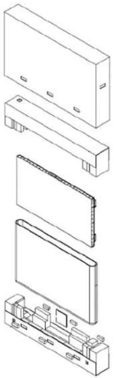
Each LCD panel is packed inside a box carton. To protect the panel during transportation, additional packing material has been placed within the carton.
natural_image
Exploded view diagram of a device showing internal components and mounting points (no text or labels)- Before unpacking, prepare a stable, level, and clean surface near a wall outlet.
- Set the box in an upright position and pull out the white carton locks.
- Lift up the top cover carton.
- Remove the polybag before removing the display from the bottom tray carton.
- Remove any additional packaging, such as protective stickers, from the display panel.
Inspecting the display panel
Conduct an inspection on the display panel and verify the panel functions as expected before unpacking. If any damage is identified, or the panel does not function as expected, contact Christie Technical Support.
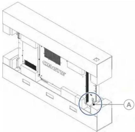
- Tear off the sticker for a small opening on the right bottom corner at the back of the display panel (A).
text_image
CREASITE A- Pull the power cable through the packaging.
- Connect the power cord to a power source and turn on the display panel.
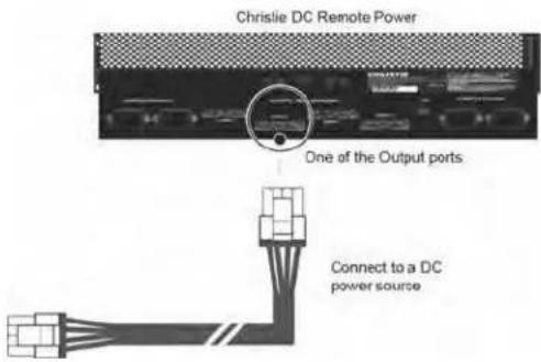
Pull out the DC power cord.
text_image
Christie DC Remote Power One of the Output ports Connect to a DC power sourceWhen connecting to a power source for the first time, the display panel automatically cycles through test patterns for 15 minutes (only).
- As the display panel is cycling through the test patterns, inspect the display.
Handling and mounting guidelines for extreme narrow bezel series panels
Follow these best practices when handling and mounting extreme narrow bezel panels.

Notice. If not avoided, the following could result in property damage.
- When moving the panel, always use the handles. Do not carry the panel by the frame.
- Do not twist, bend, or tilt the panel.
- Do not apply excessive force to the sides of the bezel when mounting the panel or pushing into its locked position.
- Always handle the display panel from the sides or handles.
Follow the following guidelines before removing the panel from the packaging.
• To verify normal operation before handling, power on the panel in the packaging.
• Always use the handles to pick up and carry the panel.
- Leave the panel in the box until the mount is on the wall and you are ready to install the panel.
- To avoid putting undue stress on the panel when mounted, make sure the mount is square, flat, and level.
- Do not rest panels on top of a lower panel.
- When inserting the panel into the wall, pay close attention to adjacent panels.
• Make sure there is a minimum of 0.5 mm between mounted panels to allow for thermal expansion.
Cleaning the panel
Learn how to clean the display panel.
After disconnecting the power cable, wipe contaminated parts and each part of the product screen lightly with a dry and soft cloth.
Do not use a liquid, spray cleaners, or any abrasive cleaners to clean the LCD panel.
Washing with various cleaning agents, brighteners, abrasives, waxes, benzene, alcohol, solvent, surface active agent, may damage the surface of the product.
Important safeguards
To prevent personal injury and to protect the device from damage, read and follow these safety precautions.
General safety precautions
Observe these important safety rules to avoid personal injury or damage to the product.

Warning! If not avoided, the following could result in death or serious injury.
- "Ensure that any external equipment is properly grounded before connecting to the display device".
- A minimum of two people or appropriately rated lift equipment is required to safely lift, install, or move the product.
- Do not drop the product.
- Do not apply excessive force to the sides of the bezel when mounting the panel or pushing into its locked position.
• Always handle the product on the opposing corners of the bezel to avoid direct contact with the glass.
• TIP HAZARD! When shipping a panel, use the provided packing materials and secure to a pallet. - When moving the panel, always use the handles. Do not carry the panel by the frame.

Caution! If not avoided, the following could result in minor or moderate injury.
• Do not tilt the product more than ±15 degrees.
- Use the handles when moving the shipping package.
- Do not twist, bend, or tilt the panel.

Notice. If not avoided, the following could result in property damage.
- Only clean the components with Christie approved products.
Remote Power Rack Shelf safety warnings
To prevent personal injury and to protect the device from damage, read and follow these safety precautions.

Warning! If not avoided, the following could result in death or serious injury.
• This product must be installed within a restricted access location not accessible by the general public.
- SHOCK HAZARD! Disconnect the product from AC before installing, moving, servicing, cleaning, removing components, or opening any enclosure.
- A minimum of two people or appropriately rated lift equipment is required to safely lift, install, or move the product.
- A certified electrician must be present during installation to ensure the installation meets the local electrical code.
• Install the product near an easily accessible AC receptacle.
- Hazardous voltages are present at power system inputs. The DC output, though not dangerous in voltage, has a high short-circuit current capacity that may cause severe burns and electrical arcing.
- SHOCK HAZARD! Power supply uses double pole/neutral fusing.
- Before working with live power systems, remove all metallic jewelry (such as watches, rings, metal rimmed glasses, or necklaces) and wear safety glasses with side shields at all times during the installation.
- Motors and fans may start without warning.
- Use insulated hand tools while working on live power systems.
Product documentation
For installation, setup, and user information, see the product documentation available on the Christie website. Read all instructions before using or servicing this product.
-
Access the documentation from the Christie website:
-
Go to this URL: http://bit.ly/2CqwJJO.
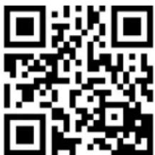
- Scan the QR code using a QR code reader app on a smartphone or tablet.
text_image
QR code image containing encoded data, no visible human-readable text- On the product page, select the model and switch to the Downloads tab.
Related documentation
Additional information on the LCD panels is available in the following documents.
• UHD654-X-HR LCD Panels User Guide (P/N: 020-001675-XX)
• UHD654-X-HR LCD Panels Product Safety Guide (P/N: 020-001683-XX)
• UHD654-X-HR LCD Display Panels External Commands (P/N: 020-001684-XX)
• LCD Panel Color Matching Guide – UHD654-X-HR and FHD554-XZ-H/HR (P/N: 020-001663-XX)
Replacement parts
When ordering replacement parts, quote the part numbers of the items required.
Some parts identified in the service parts list may not be available separately. In addition, some parts stocked as inventory are available only until the current supply lasts. All part numbers are subject-to-change. When ordering replacement parts, provide the following information found on the product license label:
- Panel Model
• Panel Serial Number Manufacture Date
• Manufacture Date
Index of parts and modules
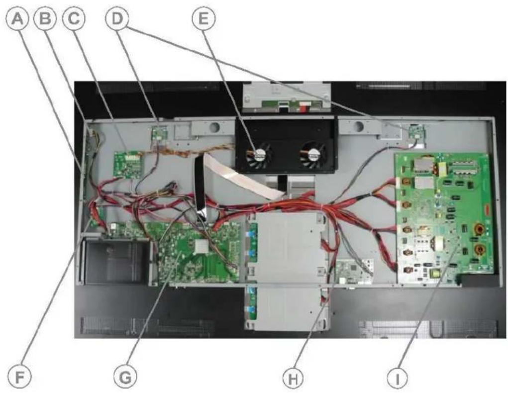
The following is a list of replaceable parts and part numbers.
Components must be replaced with exact equivalents. Failure to do so may result in unsafe operation.
text_image
A B C D E F G H I| Callout | Part number | Description |
| A | 003-121585-01 | Keypad board |
| B | 003-121863-01 | IR board |
| C | 003-121583-01 | Fan board |
| D | 003-121862-01 | Color Sensor Board |
| E | 003-121066-01 | Fan |
| F | 003-121584-01 | Sensor board |
| G | 003-121864-01 | AD board |
| H | 003-121865-01 | LAN and RS232 board |
| I | 003-121861-01 | Power board |
Replacement procedures
When reinstalling a module, follow the removal instructions in reverse unless otherwise indicated.

Caution! If not avoided, the following could result in minor or moderate injury.
- SHOCK HAZARD! Disconnect the product from DC before installing, moving, servicing, cleaning, removing components, or opening any enclosure.

Notice. If not avoided, the following could result in property damage.
- Observe all electrostatic precautions. Use a grounded wrist strap and insulated tools when handling, servicing, or cleaning electronic assemblies.
• Christie products must be installed and serviced by Christie qualified technicians.
• All procedures must be performed by Christie qualified technicians.
Follow all service safety guidelines. This panel is internationally approved and is designed for safe and reliable operation
Required tools
-
1 and #2 Phillips™ screw drivers • ESD protective strap and pad
Removing the rear cover
The rear cover houses the replaceable components of the display panel.

natural_image
Top-down view of a laptop's front panel with red circular markers indicating locations (no text or symbols visible)- Place the display panel face-down on a clean, protective surface.
- Remove the 43 Phillips screws securing the cover to the panel.
- Remove the rear cover from the display panel.
Replacing the AD board
The AD board is located on the bottom left-hand rear side of the display panel.
- Remove the rear cover.
- If present, remove the OPS module.
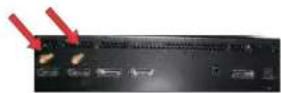
- Remove the two standoffs from the ports.
-
Mark and remove all connectors from the board.
-
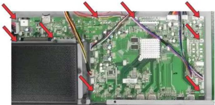
Remove the nine Phillips screws from the AD board.
natural_image
Interior view of an electronic circuit board with visible traces and components (no text or symbols)- Replace the AD board.
- To re-install, follow these steps in reverse order.
Replacing the keypad board
The keypad board is located on the left-hand rear side of the display panel.
- Remove the rear cover.
- Mark and remove all connectors from the board.
- Remove the two Phillips screws that secure the keypad board to the side of the display panel.
natural_image
Close-up of a green electronic circuit board with red arrows pointing to components (no visible text or symbols)- Replace the keypad board.
- To re-install, follow these steps in reverse order.
Replacing the sensor board
The sensor board is located on the left-hand rear side of the display panel.
- Remove the rear cover.
- Mark and remove all connectors from the board.
- Remove the two Phillips screws from the sensor board.
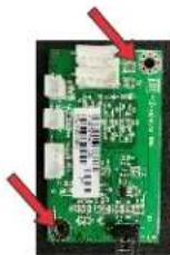
- Replace the sensor board.
- To re-install, follow these steps in reverse order.
Replacing the LAN/RS232 board
The LAN/RS232 board is located at the bottom-center rear side of the display panel.
- Remove the rear cover.
- Mark and remove all connectors from the board.
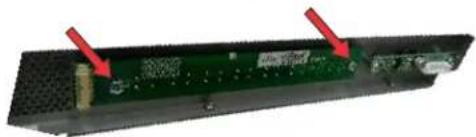
- Remove the two Phillips screws from the LAN/RS232 board.
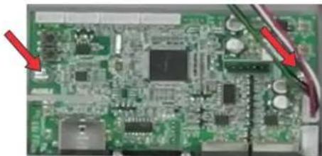
natural_image
Close-up of a green printed circuit board with visible components and red arrows pointing to specific areas (no readable text or symbols)- Replace the LAN/RS232 board.
- To re-install, follow these steps in reverse order.
Replacing the IR board
The IR board is located at the top-left rear side of the display panel.
- Remove the rear cover.
- Mark and remove all connectors from the board.
- Remove the two Phillips screws from the IR board.
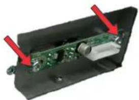
natural_image
Interior view of an electronic device showing a green circuit board and red arrows pointing to components (no text or symbols visible)- Replace the IR board.
When replacing the IR board, ensure the three sensors line up to the window.
- To re-install, follow these steps in reverse order.
Replacing the fans
The IR board is located at the top-center side of the display panel.
-
Remove the rear cover.
-
Remove the two screws securing the mounting bracket to the panel.
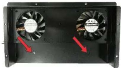
natural_image
Two black industrial fans with red arrows pointing to one side (no text or symbols visible)- Remove the four Phillips screws securing the fan to the mounting bracket.
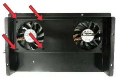
natural_image
Two black electronic fans with red arrows pointing to the side of each fan (no text or symbols visible)-
Replace the fans.
-
To re-install, follow these steps in reverse order.
Replacing the fan board
The fan board is on the middle-left rear side of the display panel.
-
Remove the rear cover.
-
Mark and remove all connectors from the board.
-
Remove the four Phillips screws from the fan board.
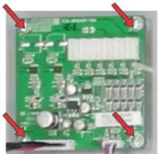
natural_image
Green printed circuit board with visible components and red arrows pointing to specific areas (no readable text or symbols)-
Replace the fan board.
-
To re-install, follow these steps in reverse order.
Replacing the color sensor boards
The color sensor board is located in the top-left and top-right rear side of the display panel.
-
Remove the rear cover.
-
Mark and remove all cables connected to the board.
-
Remove the three screws securing the color sensor board to the sensor bracket.
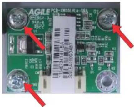
text_image
AGILE PCB-3X551HJ6-88A 02 01 02 03 04 05 06 07 08 09 10 11 12 13 14 15 16 17 18 19 20 21 22 23 24 25 26 27 28 29 30 31 32 33 34 35 36 37 38 39 40 41 42 43 44 45 46 47 48 49 50 51 52 53 54 55 56 57 58 59 60 61 62 63 64 65 66 67 68 69 70 71 72 73 74 75 76 77 78 79 80-
Replace the color sensor board.
-
To re-install, follow these steps in reverse order.
Replacing the power board
The power board is on the right-rear side of the display panel.
- Remove the rear cover.
- Mark and remove all connectors from the board.
- Remove the eight Phillips screws from the power board.
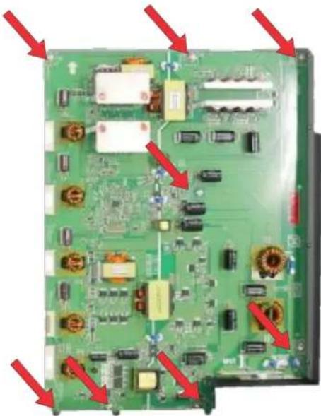
natural_image
Green printed circuit board with various electronic components and red arrows pointing to specific areas (no text or symbols visible)- Replace the power board.
- To re-install, follow these steps in reverse order.
Maintenance and troubleshooting
Learn the information and procedures for performing panel troubleshooting.
Maintenance
UHD654-X-HR display panels do not require any routine maintenance.
There are no user-serviceable or -replaceable parts. Unless you are a qualified, factory-trained technician, do not attempt to repair or replace any system component yourself. You will void the product warranty if you do so.
Troubleshooting
Learn about common issues and their solutions.
The UHD654-X-HR display panels do not require any routine maintenance. There are no user-serviceable or replaceable parts. Do not attempt to repair or replace any system component yourself unless you are a qualified, factory trained-technician, as doing so voids the product warranty.
The display does not turn on
No video is displayed on the panel.
Details
Possible causes for this issue include:
- The display is not plugged in or the power outlet is not active.
- The main power switch is off.
- The remote control batteries have run out.
Resolution
- Ensure that the display is plugged in and that the power outlet is active.
- Set the main power switch to the on position.
- Replace the batteries.
No picture appears on the display
The display is on and the menus appear, but there is no picture on the panel.
Details
Possible causes for this issue include:
- Incorrect source selection.
- Source component is not turned on.
- Source component is connected incorrectly or not at all.
Resolution
- Select the correct source.
- Turn on the source component.
- Check connections from the source component to the display.
The remote control does not work
Pressing buttons on the remote control does not affect the display.
Details
Possible causes for this issue include:
- The remote control batteries have run out.
- The buttons are locked.
- IR extender is not connected.
Resolution
- Replace the batteries.
- Unlock the buttons by pressing ENTER, ENTER, EXIT, EXIT, ENTER and EXIT, in sequence.
- Verify that the IR extender cable is correctly connected.
The image geometry is incorrect
The image is displayed with an incorrect aspect ratio.
Resolution
Select a different aspect ratio.
The content is jittery or unstable
The content on the display panel is poor-quality or the panel is improperly connected to the source.
In some cases, the horizontal or vertical scan frequency of the input signal may be out of range for the display panel.
Resolution
- Verify that the source is properly connected.
- Correct the quality of the content.
The image is too bright or lacks definition
The image contrast is set too high and the bright areas of the image have no definition.
Resolution
Decrease the contrast setting.
The image appears washed out
The dark areas of the displayed image are too bright.
Resolution
Decrease the brightness settings.
The image is too dark
The image appears too dark when the brightness or backlight are set too low.
Resolution
Increase the brightness or backlight settings.
Images from the HDMI source do not display
Source video over HDMI does not display on the panel.
Details
Possible causes for this issue include:
• The resolution and frequency of the video card in the computer are not compatible with the display.
- HDMI cable from source to display is either defective or too long.
Resolution
- Select a compatible resolution and vertical frequency.
- Try a known-good and/or shorter HDMI cable.
Computer images do not display correctly
Images that originate from a computer source do not display correctly on the panel.
Details
Possible causes for this issue include:
- The resolution and frequency of the video card in the computer are not compatible with the display.
- Clock and Phase settings need adjustment.
Resolution
- Select a compatible resolution and vertical frequency.
- Adjust Clock and Phase settings.
Corporate offices
| Christie Digital Systems USA, IrCypressph: 714 236 8610 |
| Christie Digital Systems Canada IrKitchenerph: 519 744 8005 |
Worldwide offices
| Australiaph: +61 (0) 7 3624 4888 |
| Brazilph: +55 (11) 2548 4759 |
| China (Beijing)ph: +86 10 6561 0240 |
| China (Shanghai)ph: +86 21 6278 7708 |
| Franceph: +33 (0) 1 41 21 44 04 |
| Germanyph: +49 2161 664540 |
| Indiaph: +91 (080) 6708 9 |
| Japan (Tokyo)ph: 81 3 3599 7481 |
| Korea (Seoul)ph: +82 2 702 1601 |
| Mexicoph: +52 55 4744 1790 |
| Republic of South Africph: +27 (0)11 510 0094 |
| Russian Federationand Eastern Europeph: +36 (0) 1 47 48 100 |
| Singaporeph: +65 6877 8737 |
| Spainph: +34 91 633 9990 |
| United Arab Emirateph: +971 4 3206688 |
| United Kingdomph: +44 (0) 118 977 8000 |
| United States (Arizona)ph: 602 943 5700 |
| United States (New York)ph: 646 779 2014 |
| Independent salesconsultant offices |
| Italyph: +39 (0) 2 9902 1161 |