
SYS-740GP-TNRT - Server Supermicro - Free user manual and instructions
Find the device manual for free SYS-740GP-TNRT Supermicro in PDF.


User questions about SYS-740GP-TNRT Supermicro
0 question about this device. Answer the ones you know or ask your own.
Ask a new question about this device
Download the instructions for your Server in PDF format for free! Find your manual SYS-740GP-TNRT - Supermicro and take your electronic device back in hand. On this page are published all the documents necessary for the use of your device. SYS-740GP-TNRT by Supermicro.
USER MANUAL SYS-740GP-TNRT Supermicro
natural_image
Front view of a server rack unit labeled 'SUPERMICR' with grid of ports and indicator lights (no readable text beyond label)USER'S MANUAL
Revision 1.0
The information in this User's Manual has been carefully reviewed and is believed to be accurate. The vendor assumes no responsibility for any inaccuracies that may be contained in this document, and makes no commitment to update or to keep current the information in this manual, or to notify any person or organization of the updates. Please Note: For the most up-to-date version of this manual, please see our website at www.supermicro.com.
Super Micro Computer, Inc. ("Supermicro") reserves the right to make changes to the product described in this manual at any time and without notice. This product, including software and documentation, is the property of Supermicro and/or its licensors, and is supplied only under a license. Any use or reproduction of this product is not allowed, except as expressly permitted by the terms of said license.
IN NO EVENT WILL Super Micro Computer, Inc. BE LIABLE FOR DIRECT, INDIRECT, SPECIAL, INCIDENTAL, SPECULATIVE OR CONSEQUENTIAL DAMAGES ARISING FROM THE USE OR INABILITY TO USE THIS PRODUCT OR DOCUMENTATION, EVEN IF ADVISED OF THE POSSIBILITY OF SUCH DAMAGES. IN PARTICULAR, SUPER MICRO COMPUTER, INC. SHALL NOT HAVE LIABILITY FOR ANY HARDWARE, SOFTWARE, OR DATA STORED OR USED WITH THE PRODUCT, INCLUDING THE COSTS OF REPAIRING, REPLACING, INTEGRATING, INSTALLING OR RECOVERING SUCH HARDWARE, SOFTWARE, OR DATA.
Any disputes arising between manufacturer and customer shall be governed by the laws of Santa Clara County in the State of California, USA. The State of California, County of Santa Clara shall be the exclusive venue for the resolution of any such disputes. Supermicro's total liability for all claims will not exceed the price paid for the hardware product.
FCC Statement: This equipment has been tested and found to comply with the limits for a Class A or Class B digital device pursuant to Part 15 of the FCC Rules. These limits are designed to provide reasonable protection against harmful interference when the equipment is operated in industrial environment for Class A device or in residential environment for Class B device. This equipment generates, uses, and can radiate radio frequency energy and, if not installed and used in accordance with the manufacturer's instruction manual, may cause harmful interference with radio communications. Operation of this equipment in a residential area is likely to cause harmful interference, in which case you will be required to correct the interference at your own expense.
California Best Management Practices Regulations for Perchlorate Materials: This Perchlorate warning applies only to products containing CR (Manganese Dioxide) Lithium coin cells. "Perchlorate Material-special handling may apply. See www.dtsc.ca.gov/hazardouswaste/perchlorate".

WARNING: This product can expose you to chemicals including lead, known to the State of California to cause cancer and birth defects or other reproductive harm. For more information, go to www.P65Warnings.ca.gov.
The products sold by Supermicro are not intended for and will not be used in life support systems, medical equipment, nuclear facilities or systems, aircraft, aircraft devices, aircraft/emergency communication devices or other critical systems whose failure to perform be reasonably expected to result in significant injury or loss of life or catastrophic property damage. Accordingly, Supermicro disclaims any and all liability, and should buyer use or sell such products for use in such ultra-hazardous applications, it does so entirely at its own risk. Furthermore, buyer agrees to fully indemnify, defend and hold Supermicro harmless for and against any and all claims, demands, actions, litigation, and proceedings of any kind arising out of or related to such ultra-hazardous use or sale.
Manual Revision 1.0
Release Date: May 19, 2021
Unless you request and receive written permission from Super Micro Computer, Inc., you may not copy any part of this document. Information in this document is subject to change without notice. Other products and companies referred to herein are trademarks or registered trademarks of their respective companies or mark holders.
Copyright © 2021 by Super Micro Computer, Inc.
All rights reserved.
Printed in the United States of America
Preface
About this Manual
This manual is written for professional system integrators and PC technicians. It provides information for the installation and use of the server. Installation and maintenance should be performed by experienced technicians only.
Please refer to the 740GP-TNRT server specifications page on our website for updates on supported memory, processors and operating systems (http://www.supermicro.com).
Notes
For your system to work properly, please follow the links below to download all necessary drivers/utilities and the user's manual for your server.
• Supermicro product manuals: http://www.supermicro.com/support/manuals/
- Product drivers and utilities: https://www.supermicro.com/wdl/
- Product safety info: http://www.supermicro.com/about/policies/safety_information.cfm
If you have any questions, please contact our support team at: support@supermicro.com
This manual may be periodically updated without notice. Please check the Supermicro website for possible updates to the manual revision level.
Secure Data Deletion
A secure data deletion tool designed to fully erase all data from storage devices can be found on our website: https://www.supermicro.com/about/policies/disclaimer.cfm?url=/wdl/utility/Lot9_Secure_Data_Deletion_Utility/
Warnings
Special attention should be given to the following symbols used in this manual.

Warning! Indicates important information given to prevent equipment/property damage or personal injury.

Warning! Indicates high voltage may be encountered when performing a procedure.
Contents
Chapter 1 Introduction
1.1 Overview....10
1.2 System Features .... 11
Front View....11
Drive Carrier Indicators....12
Control Panel....13
Rear View....14
LED Indicators 16
Power Supply Indicator....16
Top View....17
1.3 System Architecture ....18
Main Components....18
1.4 Motherboard Layout....19
Quick Reference ....20
System Block Diagram....22
Chapter 2 Server Installation
2.1 Overview....23
2.2 Unpacking the System 23
2.3 Preparing for Setup....23
Choosing a Setup Location....23
Rack Precautions....24
Server Precautions....24
Rack Mounting Considerations....24
Ambient Operating Temperature....24
Airflow 25
Mechanical Loading....25
Circuit Overloading....25
Reliable Ground....25
2.4 Preparing the Chassis for Rack Mounting....26
Removing the Top Tower Cover....26
Removing the Chassis Feet....26
2.5 Installing the Rails 27
Identifying the Sections of the Rack Rails....27
Installing the Inner Rails to the Chassis....28
Installing the Outer Rails to the Rack....29
2.6 Installing the Chassis into the Rack....30
Chapter 3 Maintenance and Component Installation
3.1 Removing Power ....31
3.2 Accessing the System....32
3.3 Processor and Heatsink Installation....35
The 3rd Gen Intel Xeon Scalable Processor....35
Overview of the CPU Socket 38
Overview of the Processor Carrier Assembly 39
Overview of the Processor Carrier Assembly 40
-
The 3rd Gen Intel Xeon Scalable Processor ....40
-
Processor Carrier ....40
-
Processor Carrier Assembly....40
Overview of the Processor Heatsink Module....41
-
Heatsink (with Thermal Grease)....41
-
Processor Carrier ....41
-
The 3rd Gen Intel Xeon Scalable Processor ....41
-
Processor Heatsink Module (PHM)....41
Creating the Processor Carrier Assembly....42
Creating the Processor Heatsink Module (PHM)....44
Preparing the CPU Socket for Installation....45
Preparing to Install the Processor Heatsink Module (PHM) into the CPU Socket......46
Installing the Processor Heatsink Module (PHM) 47
Removing the Processor Heatsink Module from the CPU Socket 49
Removing the Processor Carrier Assembly from the Processor Heatsink Module (PHM)..50
Removing the Processor from the Processor Carrier Assembly ....51
3.4 Memory Support and Installation ....52
Memory Support....52
Memory Support for the 3rd Gen Intel Xeon Scalable Processors....52
Memory Population Table for the 3rd Gen Intel® Xeon® Scalable Processors ....53
Intel Optane PMem 200 Series Memory Population Table....54
3.5 Motherboard Battery....55
3.6 Chassis Components ....56
Hard Drives ....56
SATA Backplane ....57
Installing Components in the 5.25" Drive Bays....57
Removing the Empty Drive Bay ....57
Adding a DVD-ROM Drive....57
3.7 CPU Air Shroud....58
3.8 System Cooling....59
System Fan Failure....59
Replacing System Fans....59
Power Supply 61
Replacing the Power Supply 61
3.9 Cable Routing Diagram....62
Chapter 4 Motherboard Connections
4.1 Power Connections 63
4.2 Headers and Connectors....64
4.3 Input/Output Ports 69
Rear I/O Ports....69
4.4 Jumpers....70
4.5 LED Indicators....73
Chapter 5 Software
5.1 Microsoft Windows OS Installation....75
5.2 Driver Installation....77
5.3 SuperDoctor ^® 5....78
5.4 BMC....79
BMC ADMIN User Password 79
Chapter 6 Optional Components
6.1 Optional Parts List....80
6.2 Passive GPU Support 81
6.3 Storage Control Card 82
6.4 Intel Virtual RAID on CPU (VROC)....83
Requirements and Restrictions....83
Supported SSDs and Operating Systems 83
Additional Information 84
Hardware Key 84
Status Indications....85
Hot Swap Drives 85
Hot-unplug 85
Hot-plug 85
6.5 TPM Security Module....86
Chapter 7 Troubleshooting and Support
7.1 Information Resources....87
Website 87
Direct Links for the 740GP-TNRT System ....87
Direct Links for General Support and Information 87
7.2 BMC Interface 88
7.3 Troubleshooting Procedures 89
No Power 89
No Video 90
System Boot Failure 90
Memory Errors 90
Losing the System's Setup Configuration....90
When the System Becomes Unstable....90
7.4 BIOS Error Beep (POST) Codes 92
Additional BIOS POST Codes 92
7.5 Crash Dump Using the BMC Dashboard....93
7.6 UEFI BIOS Recovery 94
Overview 94
Recovering the UEFI BIOS Image....94
Recovering the Main BIOS Block with a USB Device....94
7.7 CMOS Clear....99
7.8 BMC Reset....99
7.9 Where to Get Replacement Components....100
7.10 Reporting an Issue....100
Technical Support Procedures....100
Returning Merchandise for Service....100
Vendor Support Filing System 101
7.11 Feedback....101
7.12 Contacting Supermicro....102
Appendix A Standardized Warning Statements for AC Systems
Appendix B System Specifications
Appendix C BSMI
Contacting Supermicro
Headquarters
Address: Super Micro Computer, Inc.
980 Rock Ave.
San Jose, CA 95131 U.S.A.
Tel: +1 (408) 503-8000
Fax: +1 (408) 503-8008
Email: marketing@supermicro.com (General Information)
support@supermicro.com (Technical Support)
Website: www.supermicro.com
Europe
Address: Super Micro Computer B.V.
's-Hertogenbosch, The Netherlands
Tel: +31 (0) 73-6400390
Fax: +31 (0) 73-6416525
Email: sales@supermicro.nl (General Information)
support@supermicro.nl (Technical Support)
rma@supermicro.nl (Customer Support)
Website: www.supermicro.nl
Asia-Pacific
Address: Super Micro Computer, Inc.
3F, No. 150, Jian 1st Rd.
Zhonghe Dist., New Taipei City 235
Taiwan (R.O.C)
Tel: +886-(2) 8226-3990
Fax: +886-(2) 8226-3992
Email: support@supermicro.com.tw
Website: www.supermicro.com.tw
Chapter 1
Introduction
1.1 Overview
This chapter provides a brief outline of the functions and features of the SuperWorkstation 740GP-TNRT. It is based on the X12DPG-QT6 motherboard and the CSE-747BTS-R2K20BP chassis.
The following provides an overview of the specifications and capabilities.
| System Overview | |
| Chassis | CSE-747BTS-R2K20BP |
| Motherboard | X12DPG-QT6 |
| Processor Support | 3rd Gen Intel® Xeon® Scalable processors |
| Memory | Sixteen DIMM slots, up to 4TB ECC LRDIMM, DDR4-3200 MHz |
| Drive Support | Four NVMe/SATA hot-swap 3.5"/2.5" drive bays (NVMe from CPU1) Four SATA hot-swap 3.5" drive bays |
| Expansion Slots | Six PCIe 4.0 x16 slotsOne PCIe 4.0 x8 slot |
| I/O Ports | Front:Two USB 3.0 Type-A portsOne line-out portOne microphone portRear:One COM portOne dedicated BMC LAN portThree Type-A portsOne Type-C portTwo 10G LAN portsOne VGA |
| System Cooling | Six heavy duty fans |
| Power | Redundant 2200W Titanium level (96%) |
| Form Factor | Tower (4U Rackable) |
A Quick Reference Guide can be found on the product page of the Supermicro website.
The following safety models associated with the 740GP-TNRT have been certified as compliant with UL or CSA: 747-22, 747-R22X12.
1.2 System Features
The following views of the system display the main features. Refer to Appendix B for additional specifications.
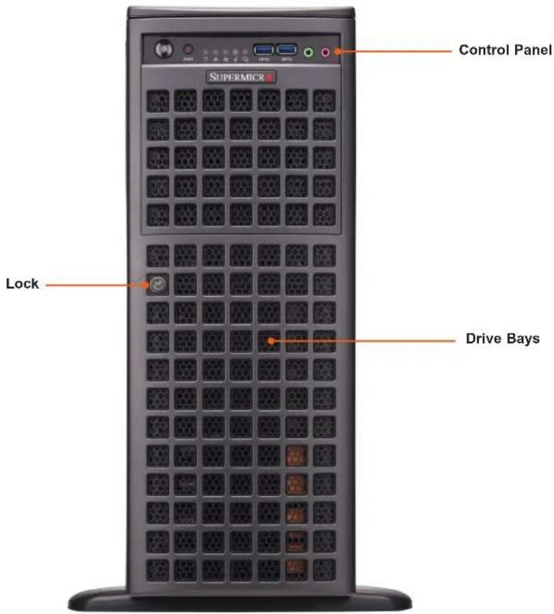
Front View
text_image
Control Panel SUPERMICR Lock Drive BaysFigure 1-1. Front View
| Logical Storage Drive Numbers | |
| Item Description | |
| HDD0~HDD3 NVMe/SATA Hybrid | |
| HDD4~HDD7 SATA | |
* SAS3 support available with additional parts; see optional parts list
Drive Carrier Indicators
Each drive carrier has two LED indicators: an activity indicator and a status indicator. For RAID configurations using a controller, the meaning of the status indicator is described in the table below. For OS RAID or non-RAID configurations, some LED indications are not supported, such as hot spare. For VROC configurations, refer to the VROC appendix in this manual.
| Drive Carrier LED Indicators | |||
| Color Blinking Pattern Behavior | for Device | ||
| Activity LED | Blue Solid On Idle NVMe drive installed | ||
| Blue Blinking NVMe/SATA I/O activity | |||
| Off N/A Idle SATA drive | |||
| Status LED | Red Solid On Failure of drive with RSTe support | ||
| Red Blinking at 1 Hz Rebuild drive with RSTe support | |||
| Red Blinking with two blinks and one stop at 1 Hz | Hot spare for drive with RSTe support | ||
| Red On for five seconds, then off | Power on for drive with RSTe support | ||
| Red Blinking at 4 Hz Identify drive with RSTe support | |||
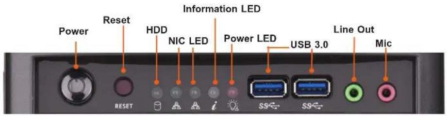
Control Panel
text_image
Power Reset HDD NIC LED Information LED Power LED USB 3.0 Line Out Mic RESET i SS SSFigure 1-2. Control Panel
| Control Panel Features | |
| Feature Description | |
| Power Button | The main power switch is used to apply or remove power from the power supply to the server.Turning off system power with this button removes the main power but maintains standby power. To perform many maintenance tasks, you must unplug system before servicing. |
| Reset Button The reset button is used to reboot the system. | |
| HDD LED Indicates hard drive activity on the hard drive when flashing. | |
| NIC LED Indicates network activity on LAN when flashing. | |
| Information LED Alerts operator of several states. See table below for details. | |
| Power Fail Indicates a power failure to the system's power supply units. | |
| USB 3.0 Two USB 3.0 ports. | |
| Line Out Line out port. | |
| Mic Mic port. | |
| Information LED | |
| Color, Status Description | |
| Red, continuously An overheat condition has occurred. | |
| Red, blinking at 1Hz Fan failure, check for an inoperative fan. | |
| Red, blinking at 0.25Hz Power failure, check for a non-operational power supply. | |
| Blue, solid | UID has been activated locally to locate the server in a rack environment. |
| Blue, blinking | UID has been activated using BMC to locate the server in a rack environment. |
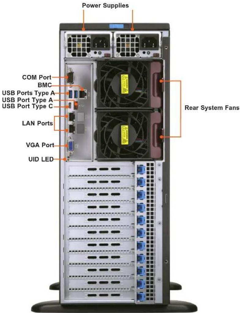
Rear View
text_image
Power Supplies COM Port BMC USB Ports Type A USB Port Type A USB Port Type C LAN Ports VGA Port UID LED Rear System FansFigure 1-3. System: Rear View
| System Features: Rear | |
| Feature Description | |
| Power Supplies Two redundant power supply modules, PWS1 on the left, PWS2 on the right | |
| COM Serial port | |
| BMC RJ45 Dedicated BMC LAN port | |
| USB Four USB 3.0 ports | |
| LAN Two LAN ports | |
| VGA Video port | |
| UID LED UID switch and rear UID LED | |
| Rear System Fans Two system fans | |
Expansion Slot Locations
| Item Description |
| Slot2 PCIe 4.0 x16 slot from CPU1 (GPU priority) |
| Slot4 PCIe 4.0 x16 slot from CPU1 (GPU priority) |
| Slot6 PCIe 4.0 x16 slot from CPU2 (GPU priority) |
| Slot8 PCIe 4.0 x16 slot from CPU2 (GPU priority) |
| Slot9 PCIe 4.0 x16 slot from CPU1 (Storage or Networking) |
| Slot10 PCIe 4.0 x16 slot from CPU2 (Storage or Networking) |
| Slot11 PCIe 4.0 x8 slot from CPU2 (Storage or Networking) |
LED Indicators
| LAN 1/2 Link LED (Left) | |
| Color Definition | |
| Green 10Gbps | |
| Yellow/Amber 1Gbps | |
| BMC LAN LED | |
| Color Definition | |
| OFF 10Mbps | |
| Green 100Mbps | |
| Amber 1Gbps | |
Power Supply Indicator
| Power Supply Indicator | |
| Power Supply Condition LED Color and State | |
| No AC Power to Power Supply Off | |
| PSU standby with AC/DC Input. Amber, solid | |
| Output On and Okay Green, solid | |
Top View

text_image
Lower Profile PCIe Slot PCIe Gen4 Slot for Storage AOC PCIe Gen4 Slot for Networking AOC Double-width Full-Length GPU Cards Dual Intel 3rd Generation Xeon Scalable Processors up to 270W M.2 Slots DIMM Slots System FansFigure 1-4. System: Top View
| System Features: Top | |
| Feature Description | |
| Power Supply Dual redundant modules | |
| Processors Dual Intel Xeon Scalable Processors | |
| DIMM Slots Sixteen dual in-line memory module (DIMMs) slots | |
| System Fans Four fans used to provide cooling for the system | |
| M.2 Slots Two M.2 slots | |
| PCIe Slot Four double-width full-length GPU cards | |
| PCIe Slot One PCIe Gen4 Slot for Networking AOC | |
| PCIe Slot One PCIe Gen4 slot for storage AOC | |
| PCIe Slot Low-profile PCIe slot | |
1.3 System Architecture
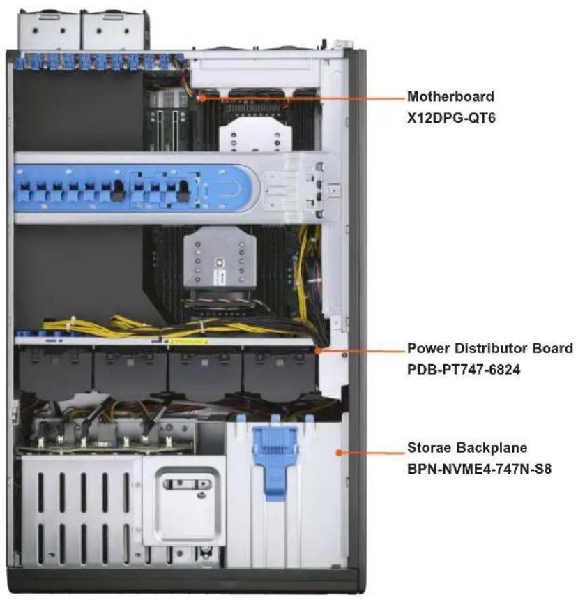
This section covers the locations of the system electrical components.
Main Components
text_image
Motherboard X12DPG-QT6 Power Distributor Board PDB-PT747-6824 Storae Backplane BPN-NVME4-747N-S8Figure 1-5. Main Component Locations
1.4 Motherboard Layout
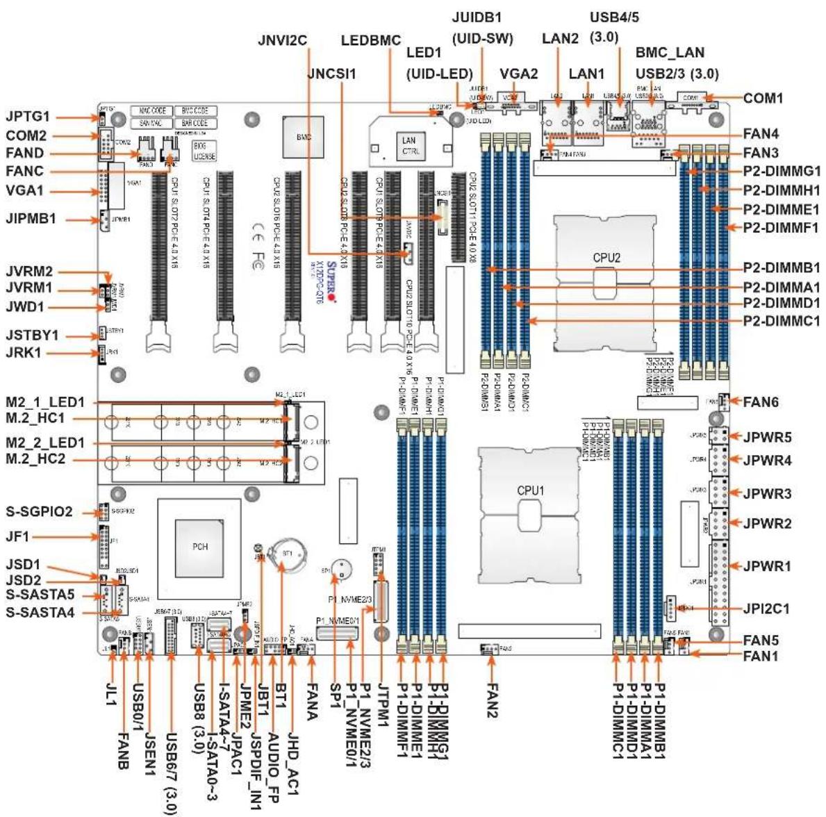
Below is a layout of the X12DPG-QT6 motherboard with jumper, connector and LED locations shown. See the table on the following page for descriptions. For detailed descriptions, pinout information and jumper settings, refer to Chapter 4 or the Motherboard Manual.
text_image
JPTG1 COM2 FAND FANC VGA1 JIPMB1 JVRM2 JVRM1 JWD1 JSTBY1 JRK1 M2_1_LED1 M.2_HC1 M2_2_LED1 M.2_HC2 S-SGPIO2 JF1 JSD1 JSD2 S-SASTA5 S-SASTA4 JL1 USB0/1 FANB JSEN1 USB6/7 (3.0) USB8 (3.0) I-SATA4-7 I-SATA0-3 JPME2_JSPDIF_IN1 JBT1_AUDIO_FP BT1_HJD_AC1 PCH JSP6/7 (3.0) USB1/1/2 USB1/1/2 USB1/1/2 JPNME2/3 P1_NVME0/1 P1_NVME0/1 P1_NVME2/3 P1_NVME0/1 P1_NVME2/3 P1_NVME0/1 P1_NVME2/3 P1_NVME0/1 P1_NVME2/3 P1_NVME0/1 P1_NVME2/3 P1_NVME0/1 P1_NVME2/3 P1_NVME0/1 P1_NVME2/3 P1_PIDIMME1 P1_DIMIME1 P1_DIMIME1 P1_DIMIME1 P1_DIMIME1 P1_DIMIME1 P1_DIMIME1 P1_DIMIME1 P1_DIMIME1 P1_DIMIME1 P1_DIMIME1 P1_DIMIME1 P1_DIMIME1 P1_DIMIME1 P1_DIMIME1 P1_DIMIME1Figure 1-6. Motherboard Layout
Quick Reference
Jumper Description Default Setting
| JBT1 CMOS Clear Open (Normal) | |
| JHD_AC1 AC97/High Definition Audio Enable Off (HD Enabled) | |
| JPAC1 Audio Enable Pins 1-2 (Enabled) | |
| JPME2 ME Manufacturing Recovery Pins 1-2 (Normal) | |
| JPTG1 LAN Port Enable/Disable Pins 1-2 (Enabled) | |
| JVRM1 VRM SMB Clock (to BMC or PCH) Pins 1-2 (BMC, Normal) | |
| JVRM2 VRM SMB Data (to BMC or PCH) Pins 1-2 (BMC, Normal) | |
| JWD1 Watchdog Timer Reset Pins 1-2 (Reset) | |
| Connector Description | |
| AUDIO_FP Front Panel Audio Header | |
| Battery (BT1) Onboard Battery | |
| COM1 Rear I/O COM Port | |
| COM2 Front COM Header | |
| FAN1 ~ FAN6, FANA ~ FAND CPU/System Fan Headers (FAN5: CPU1 Fan Header, FAN6: CPU2 Fan Header) | |
| BMC_LAN Dedicated BMC LAN Port | |
| JF1 Front Control Panel Header | |
| JIPMB1 4-pin BMC External I^2C Header | |
| JL1 Chassis Intrusion Header | |
| JNCSI1 NC-SI (Network Controller Sideband Interface) Connector | |
| JNVI ^2C NVMe I ^2C Header | |
| JPI ^2C 1 Power System Management Bus (SMB) I ^2C Header | |
| JPWR1 24-pin ATX Power Connector | |
| JPWR2, JPWR3, JPWR4 8-pin Power Connectors | |
| JPWR5 4-pin Power Connector | |
| JSD1, JSD2 SATA DOM Power Connectors 1/2 | |
| JSEN1 Inlet Sensor Header | |
| JSPDIF_IN1 Sony/Philips Digital Interface Audio Input Header | |
| JSTBY1 Standby Power Header | |
| JTPM1 Trusted Platform Module/Port 80 Header | |
| JUIDB1 Unit Identifier (UID) Button | |
| LAN1, LAN2 Ethernet LAN (RJ45) Port 1 and Port 2 | |
| M.2_HC1, M.2_HC2 PCIe 4.0 x4 M.2 Slots (with support of M-Key 2242, 2260, 2280, and 22110) | |
| P1_NVME0/1, P1_NVME2/3 PCIe 4.0 x4 SlimSAS Ports with support of four NVMe connections (0/1, 2/3) | |
| I-SATA0~3, I-SATA4~7 Intel PCH SATA 3.0 Ports (with RAID 0, 1, 5, 10) | |
| S-SATA4, S-SATA5 Powered SATA Connectors (with power pins built-in) used for SuperDOM devices | |
| S-SGPIO2 Serial Link General Purpose I/O Connection Header (for S-SATA4/5 SuperDOM support) | |
| SLOT2, SLOT4,SLOT9 PCIe 4.0 x16 Slots supported by CPU1 | |
| SLOT6, SLOT8, SLOT10 PCIe 4.0 x16 Slots supported by CPU2 |
Connector Description
SLOT11 PCIe 4.0 x8 Slot supported by CPU2
SP1 Internal Speaker/Buzzer
USB0/1 (2.0) Front Accessible USB Header with two USB 2.0 connections
USB2/3, USB4/5 (3.0) Rear I/O USB 3.0 Ports
USB6/7 (3.0) Front Accessible USB Header with two USB 3.0 connections
USB8 (3.0) Internal USB 3.0 Type-A Header
VGA1 Front VGA Header
VGA2 Rear VGA Port on the I/O back panel
VROC (JRK1) Intel VROC Key Header for NVMe RAID support
LED Description State: Status
LED1 Unit Identifier (UID) LED Solid Blue: Unit Identified
LEDBMC BMC Heartbeat LED Blinking Green: BMC Normal
M2_1_LED1, M2_2_LED1 M.2 LEDs Blinking Green: Device Working
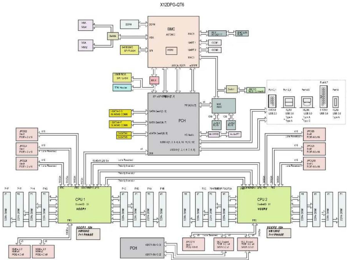
System Block Diagram
This is a general block diagram and may not exactly represent the features on your motherboard. See the System Specifications appendix for the actual specifications of your motherboard.
This chapter provides advice and instructions for mounting your system in a server rack. If your system is not already fully integrated with processors, system memory etc., refer to Chapter 3 for details on installing those specific components.
Caution: Electrostatic Discharge (ESD) can damage electronic components. To prevent such damage to PCBs (printed circuit boards), it is important to use a grounded wrist strap, handle all PCBs by their edges and keep them in anti-static bags when not in use.
2.2 Unpacking the System
Inspect the box in which the system was shipped, and note if it was damaged. If any equipment appears damaged, file a claim with the carrier.
Decide on a suitable location for the rack unit that will hold the server. It should be situated in a clean, dust-free area that is well ventilated. Avoid areas where heat, electrical noise and electromagnetic fields are generated. It will also require a grounded AC power outlet nearby. Be sure to read the precautions and considerations noted in Appendix A.
2.3 Preparing for Setup
The box in which the system was shipped should include the rackmount hardware needed to install it into the rack. Please read this section in its entirety before you begin the installation.
Choosing a Setup Location
- The system should be situated in a clean, dust-free area that is well ventilated. Avoid areas where heat, electrical noise and electromagnetic fields are generated.
- Leave enough clearance in front of the rack so that you can open the front door completely (\~25 inches) and approximately 30 inches of clearance in the back of the rack to allow sufficient space for airflow and access when servicing.
- This product should be installed only in a Restricted Access Location (dedicated equipment rooms, service closets, etc.).
- This product is not suitable for use with visual display workplace devices according to §2 of the German Ordinance for Work with Visual Display Units.
Rack Precautions
- Ensure that the leveling jacks on the bottom of the rack are extended to the floor so that the full weight of the rack rests on them.
- In single rack installations, stabilizers should be attached to the rack. In multiple rack installations, the racks should be coupled together.
- Always make sure the rack is stable before extending a server or other component from the rack.
- You should extend only one server or component at a time - extending two or more simultaneously may cause the rack to become unstable.
Server Precautions
- Review the electrical and general safety precautions in Appendix A.
- Determine the placement of each component in the rack before you install the rails.
- Install the heaviest server components at the bottom of the rack first and then work your way up.
- Use a regulating uninterruptible power supply (UPS) to protect the server from power surges and voltage spikes and to keep your system operating in case of a power failure.
- Allow any drives and power supply modules to cool before touching them.
- When not servicing, always keep the front door of the rack and all covers/panels on the servers closed to maintain proper cooling.
Rack Mounting Considerations
Ambient Operating Temperature
If installed in a closed or multi-unit rack assembly, the ambient operating temperature of the rack environment may be greater than the room's ambient temperature. Therefore, consideration should be given to installing the equipment in an environment compatible with the manufacturer's maximum rated ambient temperature (TMRA).
Airflow
Equipment should be mounted into a rack so that the amount of airflow required for safe operation is not compromised.
Mechanical Loading
Equipment should be mounted into a rack so that a hazardous condition does not arise due to uneven mechanical loading.
Circuit Overloading
Consideration should be given to the connection of the equipment to the power supply circuitry and the effect that any possible overloading of circuits might have on overcurrent protection and power supply wiring. Appropriate consideration of equipment nameplate ratings should be used when addressing this concern.
Reliable Ground
A reliable ground must be maintained at all times. To ensure this, the rack itself should be grounded. Particular attention should be given to power supply connections other than the direct connections to the branch circuit (i.e. the use of power strips, etc.).

To prevent bodily injury when mounting or servicing this unit in a rack, you must take special precautions to ensure that the system remains stable. The following guidelines are provided to ensure your safety:
- This unit should be mounted at the bottom of the rack if it is the only unit in the rack.
- When mounting this unit in a partially filled rack, load the rack from the bottom to the top with the heaviest component at the bottom of the rack.
- If the rack is provided with stabilizing devices, install the stabilizers before mounting or servicing the unit in the rack.
- Slide rail mounted equipment is not to be used as a shelf or a work space.
2.4 Preparing the Chassis for Rack Mounting
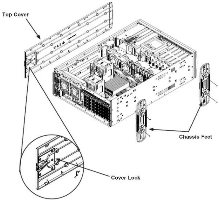
The chassis top tower cover and feet must be removed before rack installation.
Removing the Top Tower Cover
- Locate the blue cover lock at the rear of the cover.
- Slide the lock to the right and push the cover forward.
- Lift the top cover off the chassis.
text_image
Top Cover Chassis Feet Cover LockFigure 2-1. Removing the Top Tower Cover and Feet
Removing the Chassis Feet
- Lay the chassis on its side.
- Remove the screws holding the chassis feet in place.
- Each foot has a foot lock tab at the center. Use a flat head screwdriver to gently lift the foot lock upward. Slide the foot toward the rear of the chassis.
2.5 Installing the Rails
This section provides a guideline for installing the rails to the chassis and to the rack with the optional rack mount kit.
Identifying the Sections of the Rack Rails
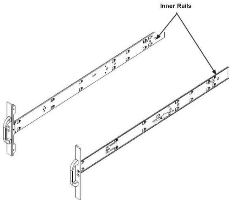
The chassis package includes two optional rack rail assemblies in the rack mounting kit. Each assembly consists of two sections: An inner fixed chassis rail that secures directly to the server chassis and an outer fixed rack rail that secures directly to the rack itself.
text_image
Inner RailsFigure 2-2. Identifying the Inner Rails and Chassis Handles
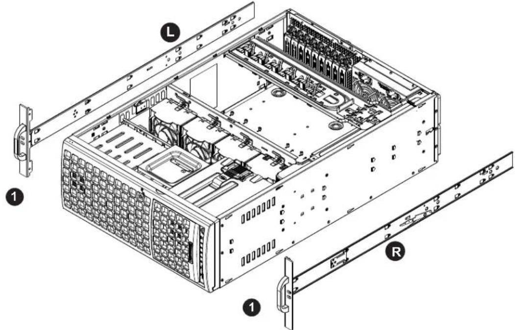
Installing the Inner Rails to the Chassis
- Attach the handles to the front of the chassis with three screws each.
- Identify the left and right inner rails. They are labeled on the rails and in the figure below.
- Align each rail with the screw holes along the side of the chassis.
- Screw the rails securely to the side of the chassis.
text_image
Technical diagram of a server rack with labeled components including drive, ports, and connectorsFigure 2-3. Installing the Handles and Inner Rails to the Chassis
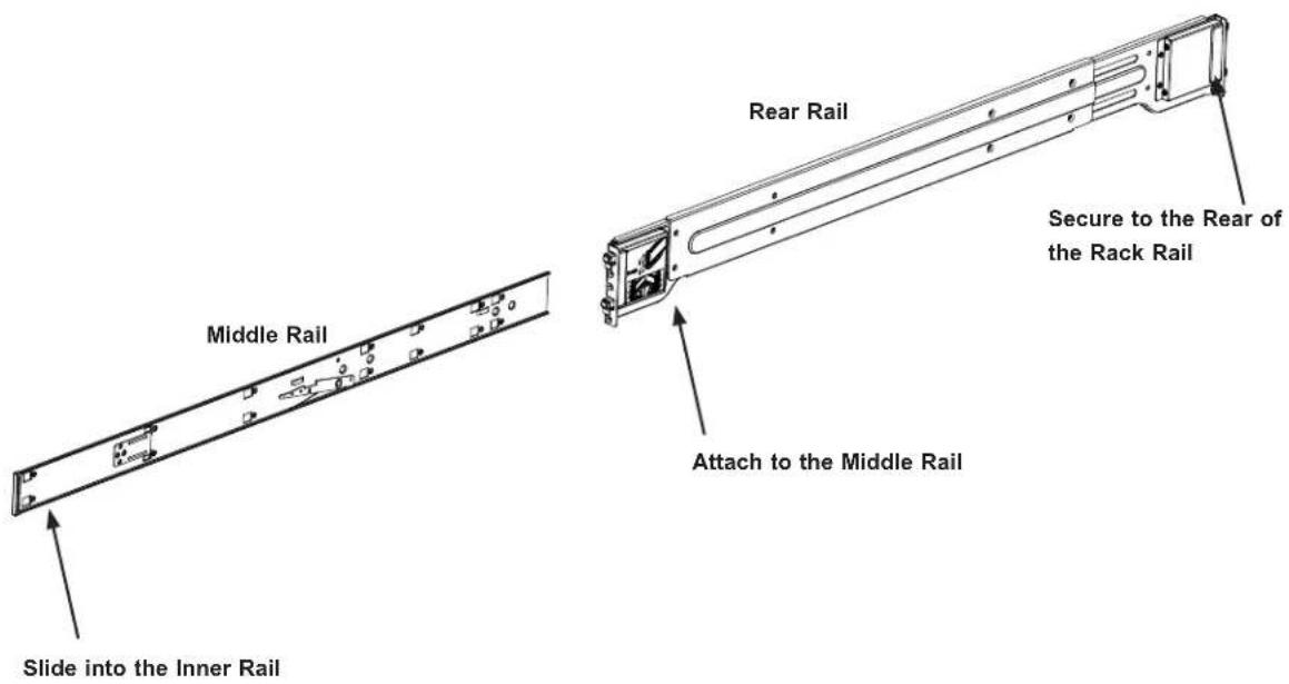
Installing the Outer Rails to the Rack
Installing the Outer Rails
- Attach the rear rail to the middle rail.
- Adjust both to the proper distance so that the rails fit snugly into the rack.
- Secure the rear rail with two M5 screws at the rear of the rack.
- Repeat steps 1-3 for the left outer rail.
text_image
Middle Rail Rear Rail Secure to the Rear of the Rack Rail Attach to the Middle Rail Slide into the Inner RailFigure 2-4. Inner and Outer Rack Rail Sections

Warning: Stability hazard. The rack stabilizing mechanism must be in place, or the rack must be bolted to the floor before you slide the unit out for servicing. Failure to stabilize the rack can cause the rack to tip over.

When initially installing the system to a rack, test that the rail locking tabs engage to prevent the system from being overextended. Have a rack lift in place as a precaution in case the test fails.
2.6 Installing the Chassis into the Rack
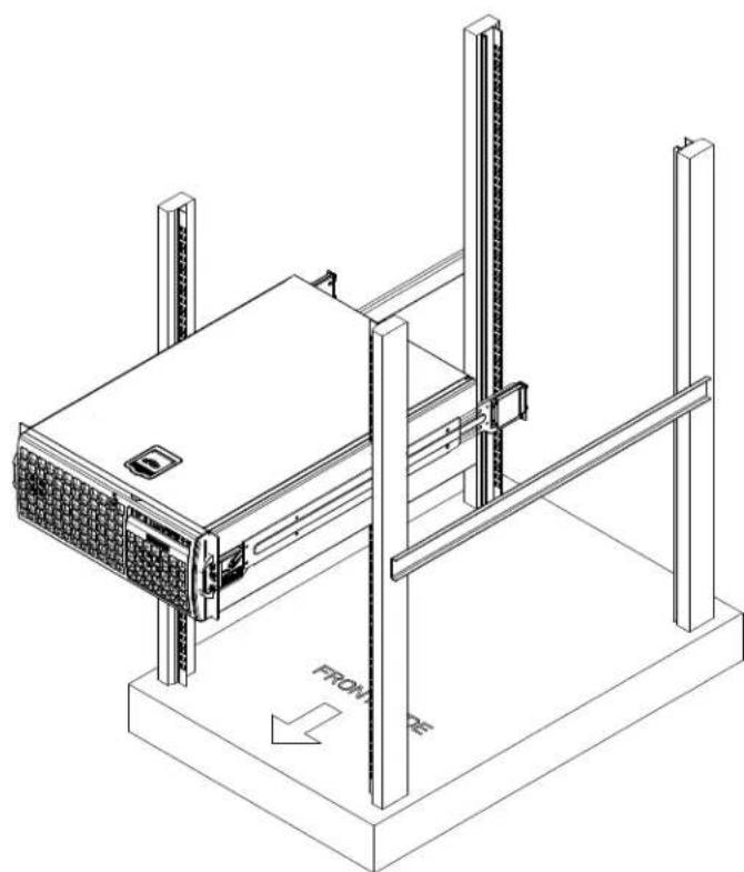
With rails attached to both the chassis and the rack, install the system into the rack.
-
Confirm that the chassis includes the inner rails and the outer rails.
-
Align the inner chassis rails with the front of the outer rack rails.
-
Slide the inner rails into the outer rails, keeping the pressure even on both sides (you may have to depress the locking tabs when inserting). When the chassis has been pushed completely into the rack, you should hear the locking tabs "click" into the locked position.
natural_image
Isometric line drawing of a server rack with vertical supports and a front panel, no text or symbols presentFigure 2-5. Installing the Server into the Rack
Note: The figure is for illustrative purposes only. Always install servers to the bottom of a rack first.
Chapter 3
Maintenance and Component Installation
This chapter provides instructions on installing and replacing main system components. To prevent compatibility issues, only use components that match the specifications and/or part numbers given.
Installation or replacement of most components require that power first be removed from the system. Please follow the procedures given in each section.
3.1 Removing Power
Use the following procedure to ensure that power has been removed from the system. This step is necessary when removing or installing non hot-swap components or when replacing a non-redundant power supply.
- Use the operating system to power down the system.
- After the system has completely shut-down, disconnect the AC power cord(s) from the power strip or outlet. (If your system has more than one power supply, remove the AC power cords from all power supply modules.)
- Disconnect the power cord(s) from the power supply module(s).
3.2 Accessing the System
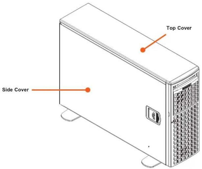
The CSE-747BTS-R2K20BP chassis features a removable top cover, which allows easy access to the inside of the chassis.
Removing the Top Cover
- Press the two release buttons and slide the cover toward the rear.
- Lift the top cover up.
Check that all ventilation openings on the top cover and the top of the chassis are clear and unobstructed.
Caution: Except for short periods of time, do not operate the server without the cover in place. The chassis cover must be in place to allow for proper airflow and to prevent overheating.
text_image
Top Cover Side CoverFigure 3-1. Identifying the Chassis Covers
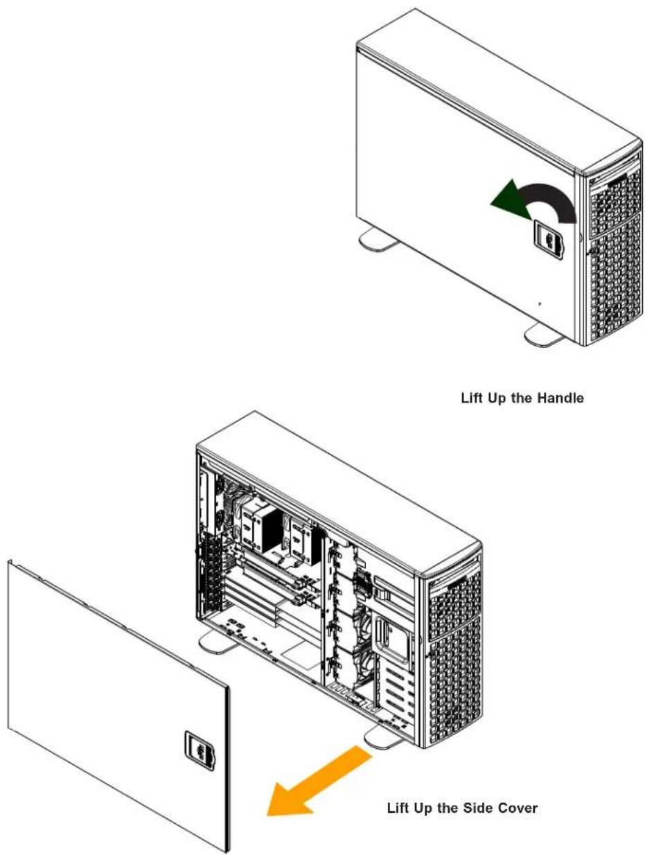
Removing the Side Cover
- Remove power from the system as described in Section 3.1.
- Lift the handle at the side of the tower.
- Lift the cover from the chassis.
text_image
Lift Up the Handle Lift Up the Side CoverFigure 3-2. Removing the Side Cover
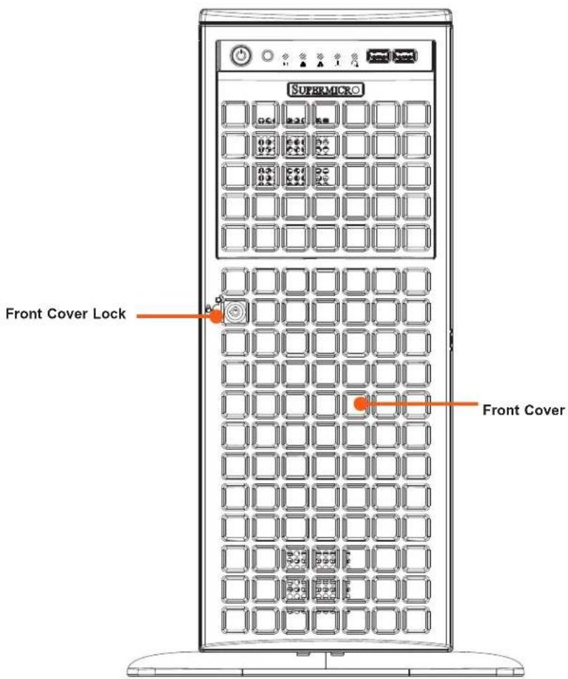
Opening the Front Cover
The front cover houses up to eight hot-swappable hard drives. The cover can be locked to prevent unauthorized access. The key to this lock is shipped with the system.
- Unlock the front cover using the key shipped with the system.
- Gently pull the cover open.
text_image
SUPERMICRO Front Cover Lock Front CoverFigure 3-3. Opening the Front Cover
3.3 Processor and Heatsink Installation
The processor (CPU) and processor carrier should be assembled together first to form the processor carrier assembly. This will be attached to the heatsink to form the processor heatsink module (PHM) before being installed onto the CPU socket.
Notes:
• Use ESD protection.
- Unplug the AC power cord from all power supplies after shutting down the system.
- Check that the plastic protective cover is on the CPU socket and none of the socket pins are bent. If they are, contact your retailer.
- When handling the processor, avoid touching or placing direct pressure on the LGA lands (gold contacts). Improper installation or socket misalignment can cause serious damage to the processor or CPU socket, which may require manufacturer repairs.
• Thermal grease is pre-applied on a new heatsink. No additional thermal grease is needed.
• Refer to the Supermicro website for updates on processor support.
- All graphics in this manual are for illustration only. Your components may look different.
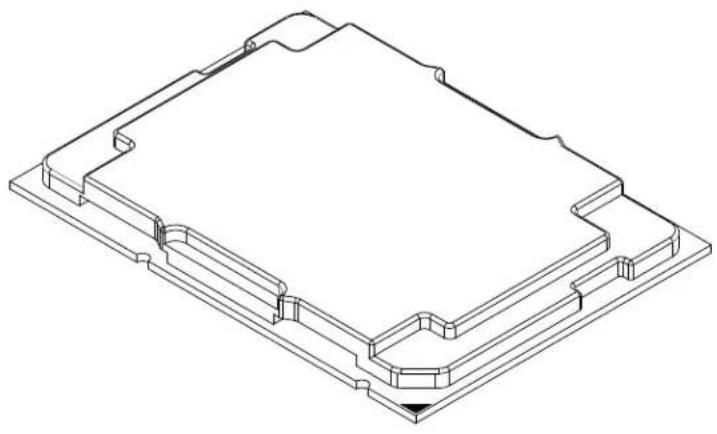
The 3rd Gen Intel Xeon Scalable Processor
- The 3rd Gen Intel Xeon Scalable Processor
natural_image
Isometric technical drawing of a mechanical housing or enclosure with stepped components and a central rectangular cavity (no text or symbols)Processor Top View
Figure 3-2. Processor
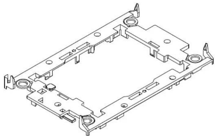
2. The Processor Carrier
natural_image
Isometric technical drawing of a mechanical housing or bracket assembly (no text or symbols)
natural_image
Pure technical line drawing of a mechanical or electronic component outline without any text, numbers, or symbolsCarrier Bottom View
3. Heatsink
natural_image
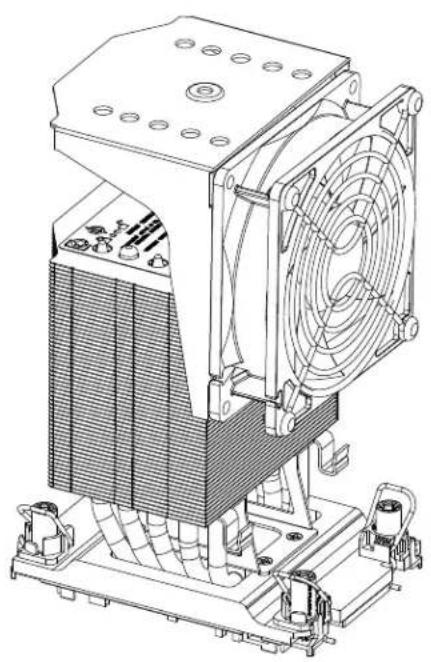
Technical line drawing of an industrial fan assembly with cooling fins and mounting brackets (no text or symbols)Note: Exercise extreme care when handling the heatsink. Pay attention to the edges of heatsink fins which can be sharp! To avoid damaging the heatsink, please do not apply excessive force on the fins when handling the heatsink.
Overview of the CPU Socket
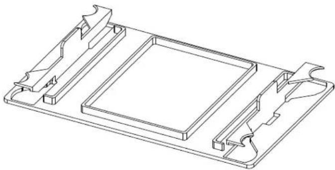
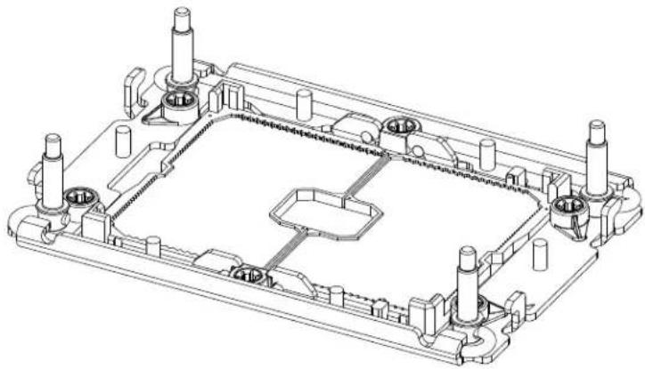
The CPU socket is protected by a plastic protective cover.
Plastic Protective Cover
natural_image
Technical line drawing of a rectangular electronic component with mounting brackets and internal compartments (no text or symbols)CPU Socket
natural_image
Technical line drawing of a mechanical housing or enclosure with multiple cylindrical components and mounting points (no text or symbols)Overview of the Processor Carrier Assembly
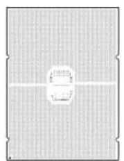
The processor carrier assembly contains a 3rd Gen Intel Xeon Scalable processor and a processor carrier. Carefully follow the instructions given in the installation section to place a processor into the carrier to create a processor carrier.
- The 3rd Gen Intel Xeon Scalable ProcessorProcessor Carrier
Intel Processor (Bottom View)
natural_image
Pure grid pattern with a central circular shape and no text or symbolsProcessor (2D)
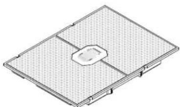
natural_image
Isometric technical drawing of a rectangular electronic component with a central mounting hole (no text or symbols)Processor
- Processor Carrier
Intel Processor Carrier (Top View)
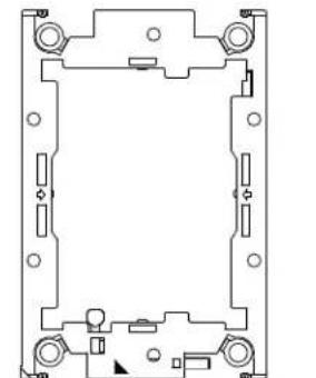
natural_image
Pure technical line drawing of a mechanical component without any text, numbers, or symbolsProcessor Carrier (2D)
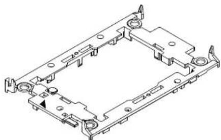
natural_image
Isometric technical drawing of a mechanical housing or bracket component (no text or symbols)Processor Carrier (3D)

- Processor Carrier Assembly
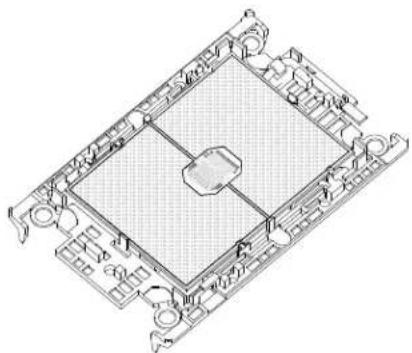
natural_image
Isometric technical drawing of a rectangular electronic component with internal grid structure (no text or symbols)(with Processor Seated inside the Carrier)
Overview of the Processor Carrier Assembly
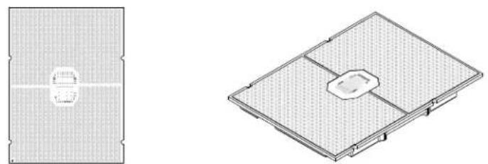
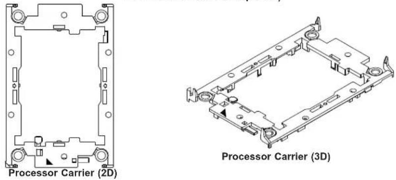
The processor carrier assembly contains a 3rd Gen Intel Xeon Scalable processor and a processor carrier. Carefully follow the instructions given in the installation section to place a processor into the carrier to create a processor carrier.
1. The 3rd Gen Intel Xeon Scalable Processor
Intel Processor (Bottom View)
natural_image
Technical diagram showing two views of a grid-patterned panel or enclosure with internal cutouts (no text or symbols)Processor (2D) Processor (3D)
2. Processor Carrier
Intel Processor Carrier Top View)
text_image
Processor Carrier (2D) Processor Carrier (3D)3. Processor Carrier Assembly

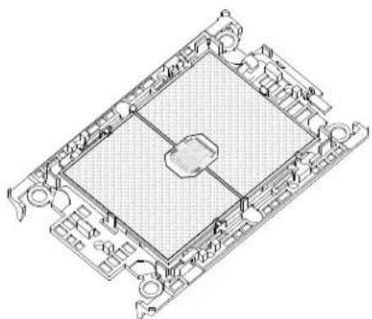
natural_image
Technical line drawing of a rectangular electronic component with internal grid structure (no text or symbols)(with Processor Seated inside the Carrier)
Overview of the Processor Heatsink Module
The Processor Heatsink Module (PHM) contains a heatsink, a processor carrier, and a 3rd Gen Intel Xeon Scalable processor.
1. Heatsink (with Thermal Grease)
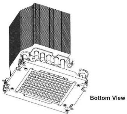
natural_image
Technical line drawing of a server rack with grid socket and mounting bracket (no text or symbols)2. Processor Carrier

natural_image
Technical line drawing of a mechanical assembly with no visible text or symbols3. The 3rd Gen Intel Xeon Scalable Processor
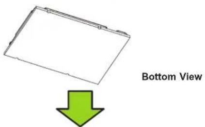
text_image
Bottom View4. Processor Heatsink Module (PHM)
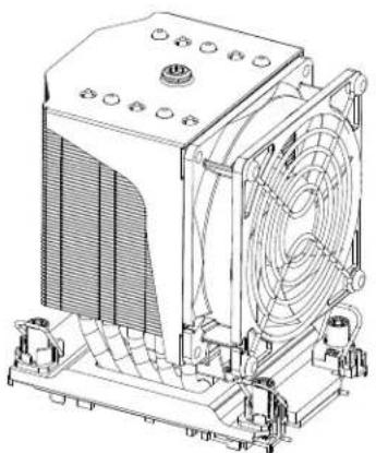
natural_image
Technical line drawing of a computer cooling unit with fan and cooling fins (no text or symbols)Creating the Processor Carrier Assembly
The processor carrier assembly contains a 3rd Gen Intel Xeon Scalable processor and a processor carrier.
To create the processor carrier assembly, please follow the steps below:
- Hold the processor with the LGA lands (with Gold CPU contacts) facing down. Locate the small, gold triangle at the corner of the processor and the corresponding hollowed triangle on the processor carrier as shown in the graphics below. Please note that the triangle indicates Pin 1 location.
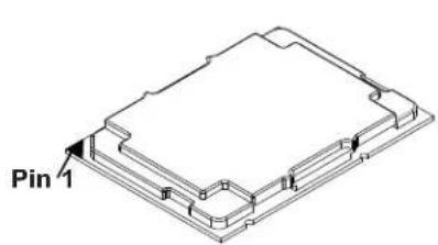
text_image
Pin 1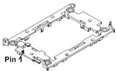
text_image
Pin 1- First, turn over the processor carrier and locate Pin 1 on the CPU and Pin 1 on the carrier. Then, turn the processor over with the processor reverse side (gold contacts) facing up and locate CPU keys on the processor. Finally, locate the CPU keys and four latches on the carrier as shown below.
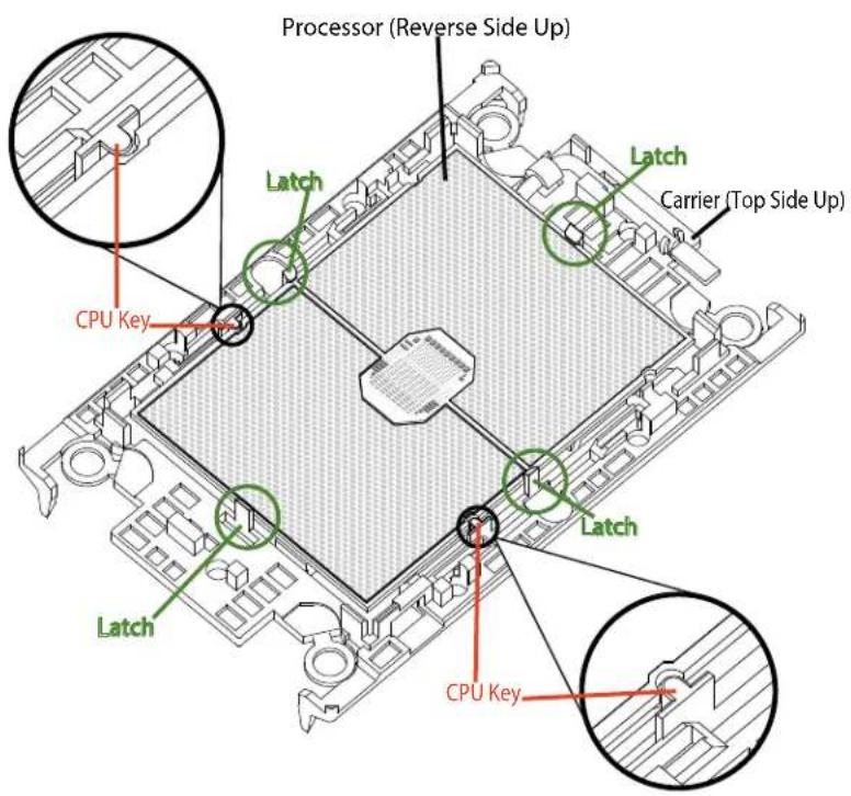
text_image
Processor (Reverse Side Up) Latch Carrier (Top Side Up) CPU Key Latch Latch Latch Latch CPU Key- Locate the lever on the CPU socket and press the lever down as shown below.
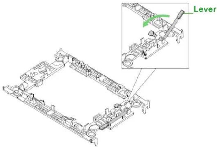
text_image
Lever-
Using Pin 1 as a guide, carefully align the CPU keys (A & B) on the processor against the CPU keys on the carrier (a & b) as shown in the drawing below.
-
Once they are properly aligned, carefully place one end of the processor into the latch marked 1 on the carrier, and place the other end of processor into the latch marked 2.
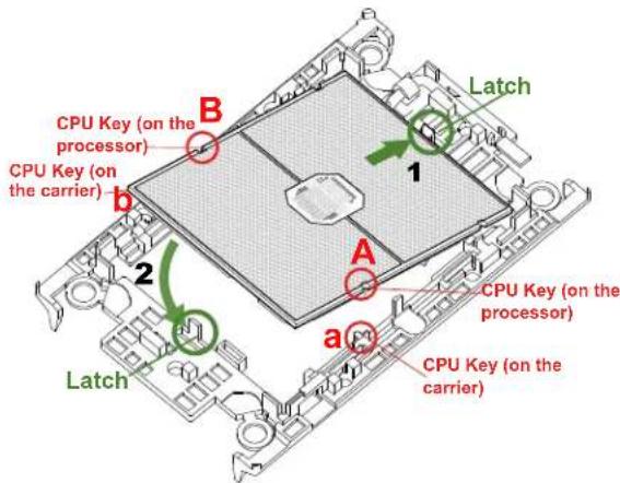
text_image
CPU Key (on the processor) CPU Key (on the carrier) Latch 1 B 2 A a Latch CPU Key (on the processor) CPU Key (on the carrier)- After the processor is placed inside the carrier, examine the four sides of the processor, making sure that the processor is properly seated on the carrier.
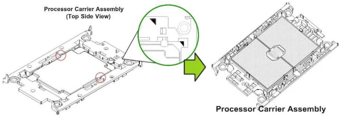
text_image
Processor Carrier Assembly (Top Side View) Processor Carrier AssemblyCreating the Processor Heatsink Module (PHM)
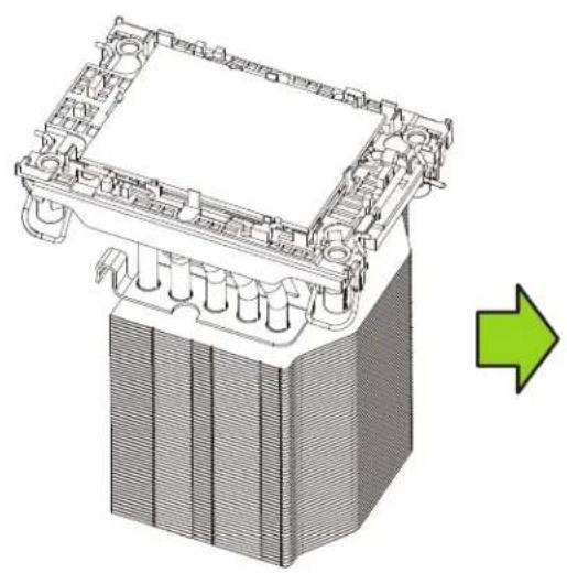
After creating the processor carrier assembly, please follow the instructions below to mount the processor carrier into the heatsink to form the processor heatsink module (PHM).
Note: If this is a new heatsink, the thermal grease has been pre-applied on the underside. Otherwise, apply the proper amount of thermal grease.
-
Turn the heatsink over with the thermal grease, which is on the reverse side of the heatsink, facing up. Pay attention to the two triangle cutouts (A, B) located at the diagonal corners of the heatsink as shown in the drawing below.
-
Hold the processor carrier assembly top side (with thermal grease) facing up, and locate the triangle on the CPU and the triangle on the carrier. (Triangle indicates Pin 1.)
-
Using Pin 1 as a guide, turn the processor carrier assembly over with the gold contacts facing up. Locate Pin 1 (A) on the processor and Pin 1 (a) on the processor carrier assembly "a".
-
Align the corner marked "a" on the processor carrier assembly against the triangle cutout "A" on the heatsink, and align the corners marked "b", "c", "d" on processor assembly against the corners marked "B", "C", "D" on the heatsinks
-
Once they are properly aligned, place the corner marked "a" on the processor carrier assembly into the corner of the heatsink marked "A". Repeat the same step to place the corners marked "b", "c", "d" on the processor carrier assembly into the corners of the heatsink marked "B", "C", "D" making sure that all plastic clips are properly attached to the heatsink.
natural_image
Technical illustration of a battery pack assembly with a green arrow indicating direction (no text or symbols present)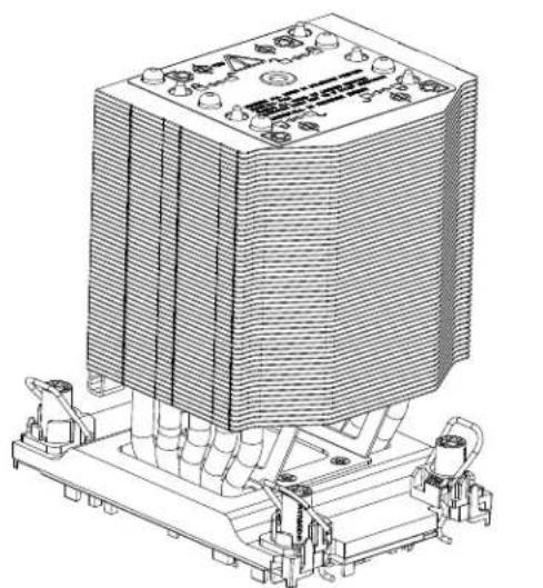
natural_image
Technical line drawing of a heat exchanger or cooling unit with cooling fins and cooling pipes (no text or symbols)Processor Heatsink Module (PHM)
Preparing the CPU Socket for Installation
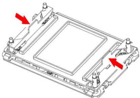
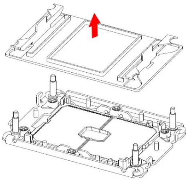
This motherboard comes with a plastic protective cover installed on the CPU socket. Remove it from the socket by following the instructions given in the drawings below.
Removing the Plastic Protective Cover from the Socket
natural_image
Technical line drawing of a mechanical component with red arrows indicating directional movement (no text or symbols)- Press the tabs inward.
natural_image
Technical line drawing of a mechanical housing assembly with mounting holes and internal components (no text or symbols)Preparing to Install the Processor Heatsink Module (PHM) into the CPU Socket
After assembling the Processor Heatsink Module (PHM), you are ready to install it into the CPU socket. To ensure the proper installation, please follow the procedures below:
- Locate four threaded fasteners (a, b, c, d) on the CPU socket.
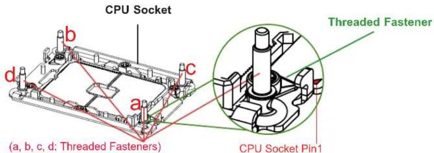
text_image
CPU Socket Threaded Fastener (a, b, c, d: Threaded Fasteners) CPU Socket Pin1- Locate four PEEK nuts (A, B, C, D) and four rotating wires (1, 2, 3, 4) on the heatsink as shown in the graphics below.
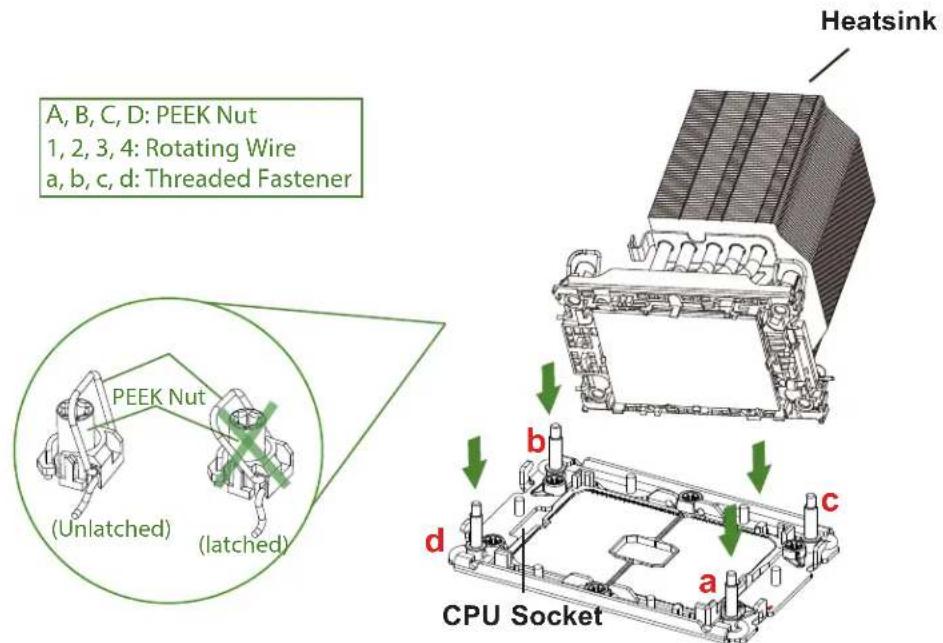
text_image
A, B, C, D: PEEK Nut 1, 2, 3, 4: Rotating Wire a, b, c, d: Threaded Fastener PEEK Nut (Unlatched) (latched) Heatsink CPU Socket b c d a- Check the rotating wires (1, 2, 3, 4) to make sure that they are at unlatched positions as shown in the drawing below before installing the PHM into the CPU socket.
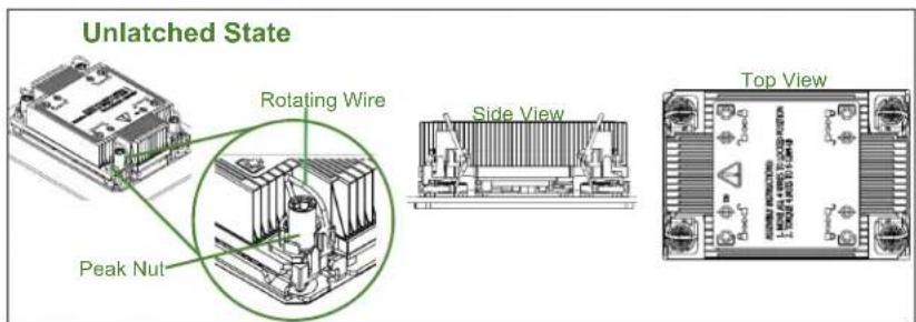
text_image
Unlatched State Rotating Wire Peak Nut Side View Top ViewInstalling the Processor Heatsink Module (PHM)
-
Align PEEK nut "A", which is next to the triangle (Pin 1) on the heatsink, against threaded fastener "a" on the CPU socket. Then align PEEK nuts "B", "C", "D" on the heatsink against threaded fasteners "b", "c", "d" on the CPU socket, making sure that all PEEK nuts on the heatsink are properly aligned with the correspondent threaded fasteners on the CPU socket.
-
Once they are aligned, gently place the Processor Heatsink Module (PHM) on top the CPU socket, making sure that each PEEK nut is properly attached to its corresponding threaded fastener.
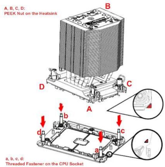
text_image
A, B, C, D: PEEK Nut on the Heatsink B D C A b c d a, b, c, d: Threaded Fastener on the CPU Socket-
Press all four rotating wires outwards and make sure that the heatsink is securely latched unto the CPU socket.
-
With a T30-bit screwdriver, tighten all PEEK nuts in the sequence of "A", "B", "C", and "D" with even pressure. To avoid damaging the processor or socket, do not use a force greater than 12 lbf-in when tightening the screws.
-
Examine all corners heatsink to ensure that the PHM is firmly attached to the CPU socket.
-
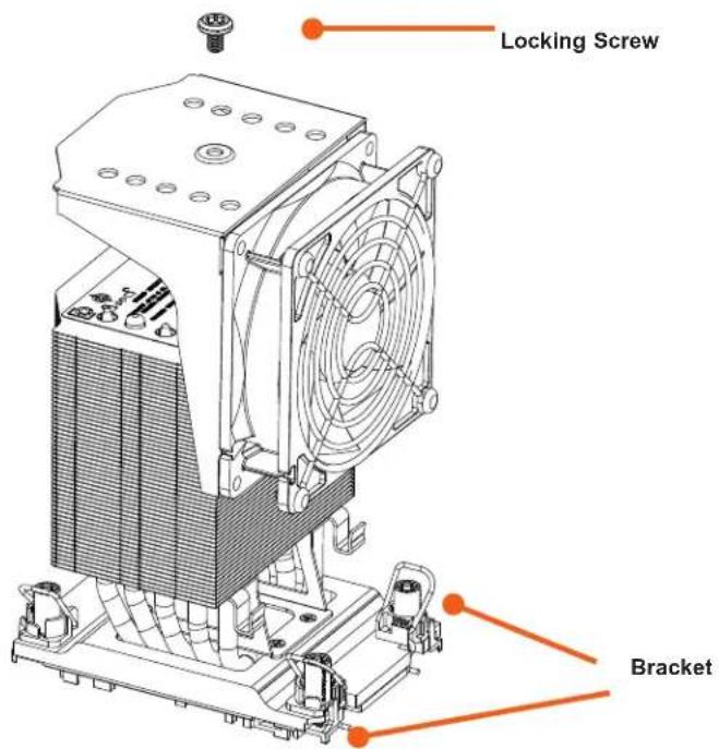
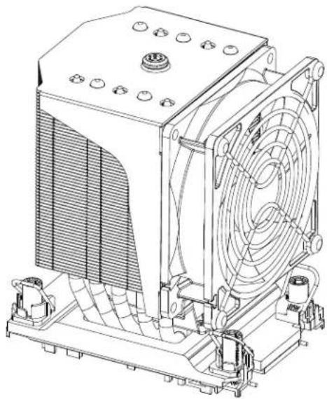
Install the cooling fan with the holder assembly onto the heatsink fin array, and ensure that it i fully engaged with the bracket.
- Tighten the locking screw on the top of the fan holder to secure it to the heatsink.
text_image
Locking Screw Bracket- Plug in the fan connector to the motherboard 4-pin fan header.
natural_image
Technical line drawing of a mechanical cooling unit with fan and cooling fins (no text or symbols)Removing the Processor Heatsink Module from the CPU Socket
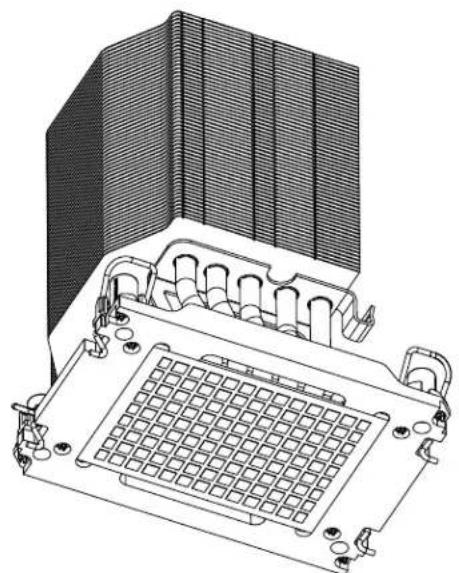
Before removing the processor heatsink module (PHM) from the motherboard, unplug the AC power cord from all power supplies after shutting down the system. Then follow the steps below:
- Use a T30-bit screwdriver to loosen the four peek nuts on the heatsink in the sequence of #A, #B, #C, and #D.
- Once the peek nuts are loosened from the CPU socket, press the rotating wires inwards to unlatch the PHM from the socket as shown in the drawings below.
- Gently lift the PHM upwards to remove it from the CPU socket.
natural_image
Technical line drawing of a mechanical component with grid pattern and mounting holes (no text or symbols)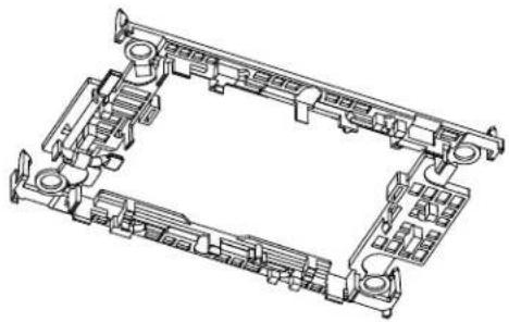
natural_image
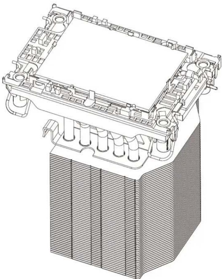
Technical line drawing of a mechanical assembly with no visible text or symbolsRemoving the Processor Carrier Assembly from the Processor Heatsink Module (PHM)
To remove the processor carrier assembly from the PHM, please follow the steps below:
-
Detach four plastic clips (marked a, b, c, d) on the processor carrier assembly from the four corners of heatsink (marked A, B, C, D) in the drawings below.
-
When all plastic clips are detached from the heatsink, remove the processor carrier assembly from the heatsink
natural_image
Technical line drawing of a mechanical housing or cooling unit with internal components (no text or symbols)Removing the Processor from the Processor Carrier Assembly
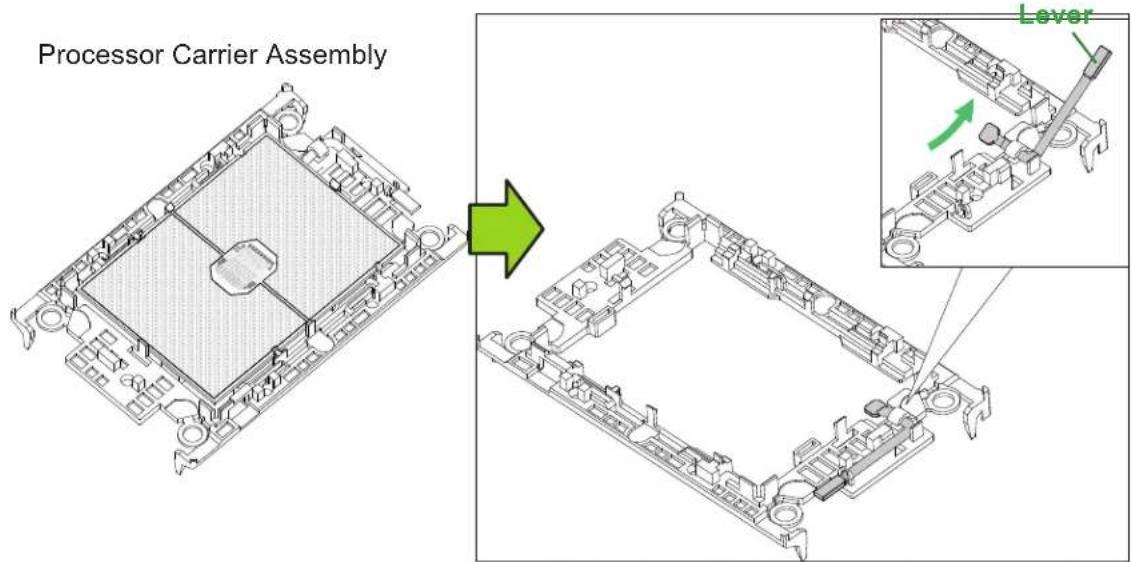
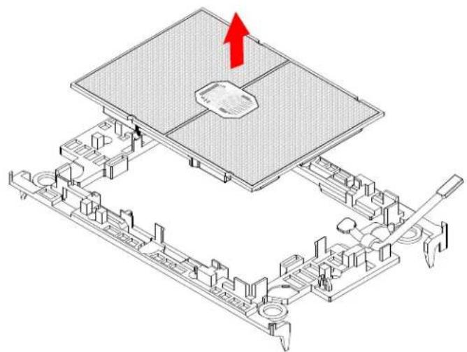
Once you have removed the processor carrier assembly from the PHM, you are ready to remove the processor from the processor carrier by following the steps below.
- Unlock the lever from its locking position and push the lever upwards to disengage the processor from the processor carrier as shown in the right drawing below.
text_image
Processor Carrier Assembly Lever- Once the processor is loosened from the carrier, carefully remove the processor from the processor carrier.
Note: To avoid damaging the processor and its pins, please handle the processor with care.
natural_image
Isometric technical diagram of a computer motherboard with a highlighted component and red arrow indicating upward motion (no text or symbols)3.4 Memory Support and Installation
Note: Check the Supermicro website for recommended memory modules.
Important: Exercise extreme care when installing or removing DIMM modules to prevent any possible damage.
Memory Support
The X12DPG-QT6 supports up to 4 TB of 3DS LRDIMM/LRDIMM/3DS RDIMM/RDIMM DDR4 (288-pin) ECC memory with speeds of 3200/2933/2666 MHz in 16 memory slots and up to 4 TB of Intel Optane PMem 200 Series with speeds of up to 3200 MHz. (See the notes below.)
Note 1: Intel Optane PMem 200 Series is supported by the 3rd Gen Intel® Xeon® Scalable processors only.
Note 2: P1-DIMMB1/P2-DIMMB1 memory slots are reserved for Intel Optane PMem 200 Series only.
Note 3: Memory speed support depends on the processors used in the system.
Memory Support for the 3rd Gen Intel Xeon Scalable Processors
| Memory Support for the 3rd Gen Intel® Xeon® Scalable processors | |||||
| Type | Ranks Per DIMM & Data Width | DIMM Capacity (GB) | Speed (MT/s); Voltage (V); Slot Per Channel (SPC) and DIMM Per Channel (DPC) | ||
| 1DPC (1-DIMM Per Channel) | 2DPC (2-DIMM Per Channel) | ||||
| 8Gb 16Gb | 1.2 V 1.2 V | ||||
| RDIMM | SRx8 8GB 16GB | 3200 2933* | |||
| SRx4 16GB 32GB | |||||
| DRx8 16GB 32GB | |||||
| DRx4 32GB 64GB | |||||
| RDIMM-3DS (4R/8R)x4 | 2H-64GB4H-128GB | 2H-128GB4H-256GB | |||
| LRDIMM | QRx4 | 64GB | 128GB | 3200 | 3200 |
| LRDIMM-3DS (4R/8R)x4 | 4H-128GB | 2H-128GB4H-256GB | 3200 | 3200 | |
Memory Population Table for the 3rd Gen Intel® Xeon® Scalable Processors
| Memory Population for the X12 DP Motherboard, 16 DIMM Slots | |
| CPUs/DIMMs Memory Population Sequence | |
| 1 CPU & 1 DIMM | A1 |
| 1 CPU & 2 DIMMs | A1, E1 |
| 1 CPU & 3 DIMMs* | A1, C1, E1 |
| 1 CPU & 4 DIMMs | A1, C1, E1, G1 |
| 1 CPU & 5 DIMMs* | A1, B1, C1, E1, G1 |
| 1 CPU & 6 DIMM | A1, B1, C1, E1, F1, G1 |
| 1 CPU & 7 DIMMs* | A1, B1, C1, D1, E1, F1, G1 |
| 1 CPU & 8 DIMMs | A1, B1, C1, D1, E1, F1, G1, H1 |
| 2 CPUs & 2 DIMMs | CPU1: A1CPU2: A1 |
| 2 CPUs & 4 DIMMs | CPU1: A1, E1CPU2: A1, E1 |
| 2 CPUs & 6 DIMMs* | CPU1: A1, C1, E1, F1CPU2: A1, E1 |
| 2 CPUs & 8 DIMMs | CPU1: A1, C1, E1, F1CPU2: A1, C1, E1, F1 |
| 2 CPUs & 10 DIMMs* | CPU1: A1, B1, C1. E1, F1, G1CPU2: A1, C1, E1, F1 |
| 2 CPUs & 12 DIMMs | CPU1: A1, B1, C1. E1, F1, G1CPU2: A1, B1, C1. E1, F1, G1 |
| 2 CPUs & 14 DIMMs* | CPU1: A1, B1, C1. D1, E1, F1, G1, H1CPU2: A1, B1, C1. E1, F1, G1 |
| 2 CPUs & 16 DIMMs | CPU1: A1, B1, C1. D1, E1, F1, G1, H1CPU2: A1, B1, C1. D1, E1, F1, G1, H1 |
*Unbalanced, not recommended.
Intel Optane PMem 200 Series Memory Population Table
Note: Only 83xx/63xx/53xx/4315 processors support PMem 200 Series.
| 16-DIMM Motherboard PMem Population within 1 CPU socket | ||||||||||
| DDR4+Pmem | Mode AD Interleave P1-DIMMF1 P1-DIMME1 | P1-DIMMH1 P1-DIMMG1 P1-DIMMC1 P1-DIMMD1 P1-DIMMA1 P1-DIMMBI | ||||||||
| 4+4 | ADMM | One - x4 | PMem | DDR4 | PMem | DDR4 | DDR4 | PMem | DDR4 | PMem |
| One - x4 | DDR4 | PMem | DDR4 | PMem | PMem | DDR4 | PMem | DDR4 | ||
| 6+1 | AD | One - x1 | DDR4 | DDR4 | - | DDR4 | DDR4 | PMem | DDR4 | DDR4 |
| - | DDR4 | DDR4 | DDR4 | DDR4 | DDR4 | DDR4 | PMem | |||
| DDR4 | DDR4 | PMem | DDR4 | DDR4 | - | DDR4 | DDR4 | |||
| PMem | DDR4 | DDR4 | DDR4 | DDR4 | DDR4 | DDR4 | - | |||
| DDR4 | DDR4 | DDR4 | - | PMem | DDR4 | DDR4 | DDR4 | |||
| DDR4 | - | DDR4 | DDR4 | DDR4 | DDR4 | PMem | DDR4 | |||
| DDR4 | DDR4 | DDR4 | PMem | - | DDR4 | DDR4 | DDR4 | |||
| DDR4 | PMem | DDR4 | DDR4 | DDR4 | DDR4 | - | DDR4 | |||
| Legend (for the table above) | |
| DDR4 Type and Capacity | |
| DDR4 | See Validation Matrix (DDR4 DIMMs validated with DCPMM) |
| Capacity | |
| PMem | Any Capacity (Uniformly for all channels for a given configuration) |
- Mode definitions: AD = App Direct Mode, MM = Memory Mode.
- No mixing of PMem and NVDIMMs within the platform.
- For MM, NM/FM ratio is between 1:4 and 1:16. The capacity not used for FM can be used for AD. (NM = Near Memory; FM = Far Memory).
- Matrix targets config for optimized PMem to DRAM cache ratio in MM mode.
- For each individual population, different PMem rearrangements among channels are permitted so long as the configuration doesn't break X12 DP Memory population rules.
- Ensure the same DDR4 DIMM type and capacity are used for each DDR4 + PMem population.
- If the system detects an unvalidated configuration, then the system issues a BIOS warning. The CLI functionality is limited in non-POR configurations, and select commands will not be supported.
| Validation Matrix (DDR4 DIMMS w/PMem 200 Series) | |||
| DIMM Type | Ranks Per DIMM & Data Width (Stack) | DIMM Capacity (GB) | |
| DRAM Density | |||
| 8Gb | 16Gb | ||
| RDIMM (up to 3200) | 1Rx8 | N/A | N/A |
| 1Rx4 | 16GB | 32GB | |
| 1Rx8 | 16GB | 32GB | |
| 1Rx4 | 32GB | 64GB | |
| RDIMM 3DS (up to 3200) | 4Rx4 (2H) | N/A | 128GB |
| 8Rx4 (4H) | NA | 256GB | |
| LRDIMM (up to 3200) | 4Rx4 | 64GB | 128GB |
| LRDIMM 3DS (up to 3200) | 4Rx4 (2H) | N/A | N/A |
| 8Rx4 (4H) | 126GB | 256GB | |
3.5 Motherboard Battery
The motherboard uses non-volatile memory to retain system information when system power is removed. This memory is powered by a lithium battery residing on the motherboard.
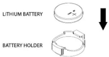
Replacing the Battery
Begin by removing power from the system.
- Push aside the small clamp that covers the edge of the battery. When the battery is released, lift it out of the holder.
- To insert a new battery, slide one edge under the lip of the holder with the positive (+) side facing up. Then push the other side down until the clamp snaps over it.
Note: Handle used batteries carefully. Do not damage the battery in any way; a damaged battery may release hazardous materials into the environment. Do not discard a used battery in the garbage or a public landfill. Please comply with the regulations set up by your local hazardous waste management agency to dispose of your used battery properly.
text_image
LITHIUM BATTERY BATTERY HOLDERFigure 3-4. Installing the Onboard Battery
Warning: There is a danger of explosion if the onboard battery is installed upside down (which reverses its polarities). This battery must be replaced only with the same or an equivalent type recommended by the manufacturer (CR2032).
3.6 Chassis Components
Hard Drives
A total of eight SATA drives may be housed in the CSE-747BTS-R2K20BP chassis. The drive IDs are preconfigured as 0 through 7 in order from bottom to top (or from left to right if rackmounted).
The drives are mounted in drive carriers to simplify their installation and removal from the chassis. (Both procedures may be done without removing power from the system.)
Removing a Hot-Swap Drive Carrier
- Open the front bezel then push the release button located beside the drive LEDs.
- Swing the handle fully out and then use it to pull the unit straight out.
Note: Your operating system must have RAID support to enable the hot-swap capability of the SATA drives.
Mounting a Drive in a Drive Carrier
The SATA drive carriers help to promote proper airflow for the system. For this reason, even carriers without SATA drives must remain in the chassis.
- To add a new drive, install it into the carrier with the printed circuit board side facing down so that the mounting holes align with those in the carrier.
- Secure the drive to the carrier with the screws provided, then push the carrier completely into the drive bay. You should hear a *click* when the drive is fully inserted. This indicates that the carrier has been fully seated and connected to the midplane, which automatically makes the power and logic connections to the hard drive.
Removing a Drive from a Drive Carrier
- Remove the screws that secure the hard drive to the carrier and separate the hard drive from the carrier.
- Replace the carrier back into the drive bay.
Note: Enterprise level hard disk drives are recommended for use in Supermicro chassis and servers. For information on recommended HDDs, visit the Supermicro website at http://www.supermicro.com/products/nfo/storage.cfm
SATA Backplane
The SATA drives plug into a drive backplane. A data cable for each drive and two LED cables need to be connected from the motherboard to the appropriate connectors on the backplane. Note that you cannot cascade the SATA backplane.
Installing Components in the 5.25" Drive Bays
The 740GP-TNRT has two 5.25" drive bays. Components such as an extra DVD-ROM drive can be installed into these 5.25" drive bays.
Removing the Empty Drive Bay
- First power down the system.
- Remove the top/left chassis cover to access the drive components.
- With the cover off, remove the screws that secure the drive carrier to the chassis (one side only) then push the entire empty drive carrier out from the back.
Adding a DVD-ROM Drive
- Remove the guide plates (one on each side) from the empty drive carrier and screw them into both sides of the DVD-ROM drive using the holes provided.
- Slide the DVD-ROM into the bay and secure it to the chassis with the drive carrier screws you first removed.
- Attach the power and data cables to the drive.
- Replace the top/left chassis cover and restore power to the system.
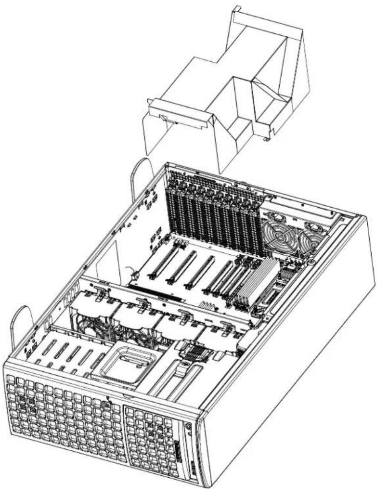
3.7 CPU Air Shroud
The air shroud is used to d to prevent the processors from overheat and concentrate airflow to maximize fan efficiency. The air shroud does not require screws to set up.
Installing the CPU Air Shroud
- Lay the chassis on a flat, stable surface and remove the chassis cover.
- If necessary, move any cables that interfere with the air shroud placement.
- Place the air shroud in the chassis. The air shroud fits just behind the three fans in the fan rack. Slide the air shroud into the grooves just behind the fan rack.
- Reroute any cables that were moved and replace the chassis cover.
natural_image
Technical line drawing of an internal server rack with visible socket, drive bays, and ventilation slots (no text or labels)Figure 3-5. Installing the Air Shroud
3.8 System Cooling
Heavy-duty fans provide cooling for the chassis. Four fans are located in the mid-section of the chassis, two fans are located in the rear, and two optional fans can be mounted on the external rear of the chassis, required for passive GPUs.
The internal fans come pre-installed to the chassis. Each fan is hot-swappable and can be replaced without removing any connections.
System Fan Failure
Fan speed is controlled by system temperature through BMC. If a fan fails, the remaining fans will ramp up to full speed. Replace any failed fan at your earliest convenience with the same type and model (the system can continue to run with a failed fan).
Replacing System Fans
The chassis contains two types of system fans: mid-system fans and rear system fans.
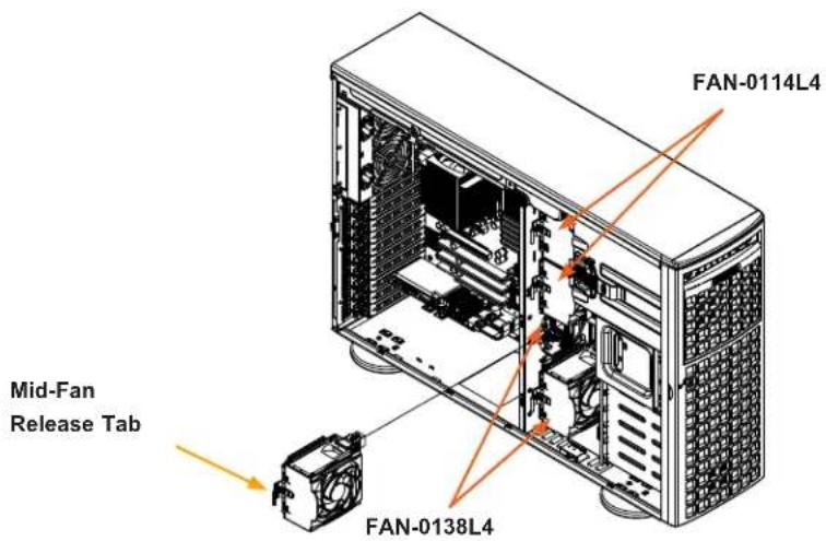
Replacing Mid-System Fans (FAN-0114L4 and FAN-0138L4)
- Determine which fan has failed. Because the fans are hot-swappable, the system does not need to be powered-down.
- Press the fan release tab and lift the failed fan from the chassis. Mid fans must be pulled straight out of the chassis. Part numbers: top two fans are FAN-0114L4 and bottom two are FAN-0138L4.
- Place the new fan into the vacant space in the housing while making sure the arrows on the top of the fan (indicating air direction) point in the same direction as the arrows on the other fans. As soon as the fan is connected, it will begin working.
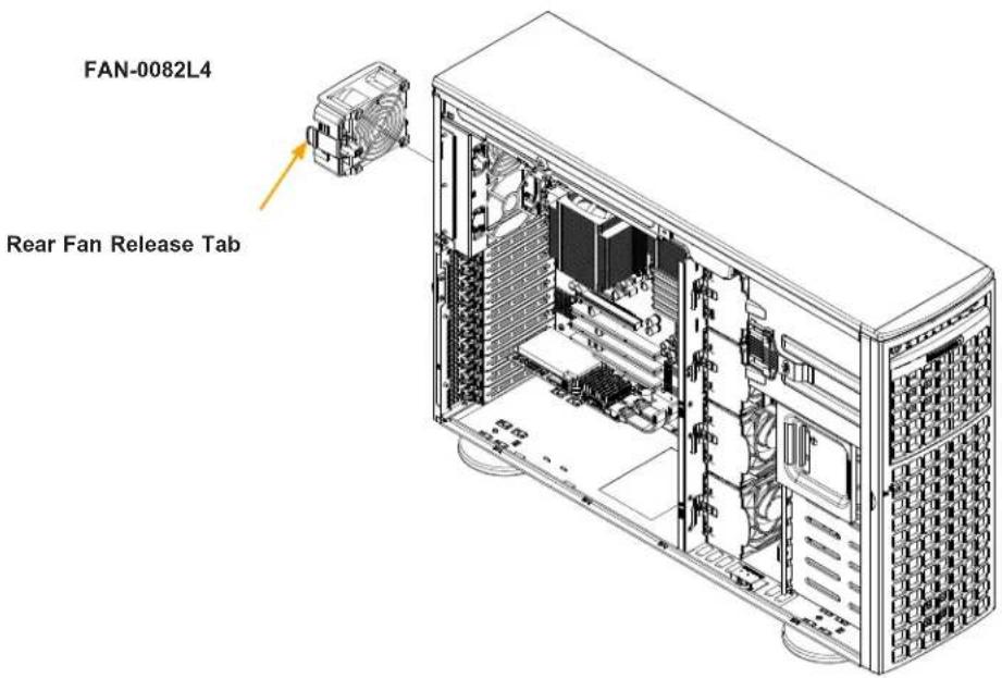
Replacing the Rear System Fan (FAN-0082L4)
- Determine which fan has failed.
- Press the rear fan release tab.
- Pull the fan away from the chassis by pulling out the top first.
- Place the new fan in the chassis, inserting the bottom of the fan first. Push the fan fully into the housing until the fan clicks into place. Power up the system and check that the fan is working properly before replacing the chassis cover.
text_image
FAN-0114L4 Mid-Fan Release Tab FAN-0138L4Figure 3-6. Mid-System Chassis Fans
text_image
FAN-0082L4 Rear Fan Release TabFigure 3-7. Rear System Chassis Fans
Power Supply
The SuperWorkstation 740GP-TNRT includes two 1+1 2200W redundant power supplies. These power supplies are auto-switching capable. This enables it to automatically sense and operate at a 100V to 240V input voltage. An amber light will be illuminated on the power supply when the power is off. An illuminated green light indicates that the power supply is operating.
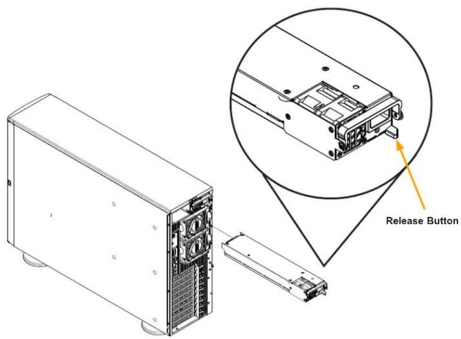
Replacing the Power Supply
- Push the release button on the back of the failed power module.
- Pull the power module out using the handle provided.
- Replace the failed power module with the same model.
- Push the new power module into the power bay until you hear a click.
text_image
Release ButtonFigure 3-8: Power Supply Release Button
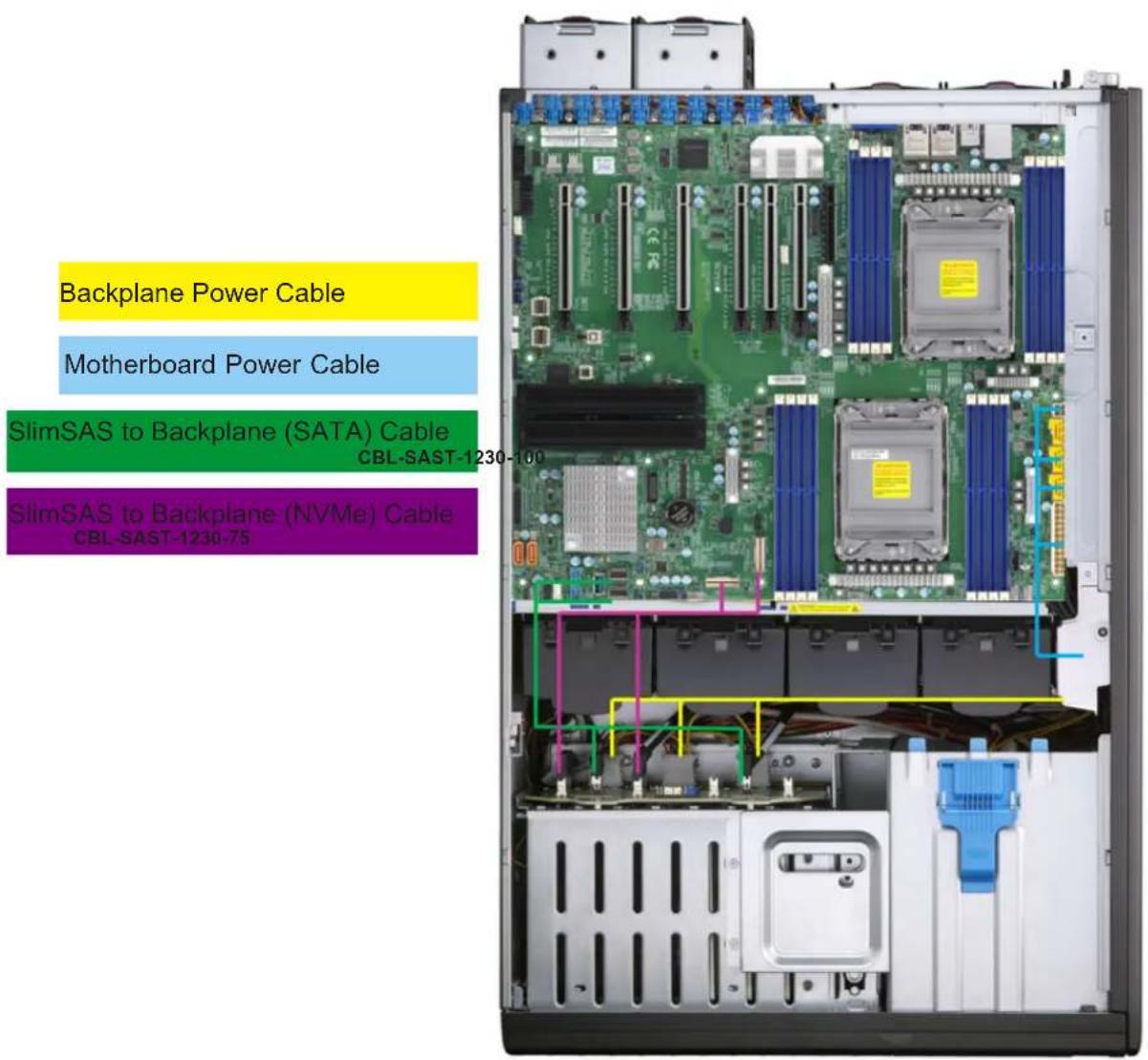
3.9 Cable Routing Diagram
Refer to the diagram below for a representation of how the main cables are routed throughout the system. When disconnecting cables to add or replace components, refer to this diagram when adding or replacing components so you can reroute them in the same manner. Proper cable routing is important in maintaining proper airflow through the system.
text_image
Backplane Power Cable Motherboard Power Cable SlimSAS to Backplane (SATA) Cable CBL-SAST-1230-100 SlimSAS to Backplane (NVMe) Cable CBL-SAST-1230-75Figure 3-9. Cable Routing Diagram
Chapter 4
Motherboard Connections
This section describes the connections on the motherboard and provides pinout definitions. Note that depending on how the system is configured, not all connections are required. The LEDs on the motherboard are also described here. A motherboard layout indicating component locations may be found in Chapter 1. More detail can be found in the Motherboard Manual Please review the Safety Precautions in Appendix A before installing or removing components.
4.1 Power Connections
Two power connections supply the motherboard and several more supply for onboard devices.
ATX Power Supply Connector
The 24-pin power supply connector (JPWR1) meets the ATX SSI EPS 12V specification. You must also connect the 8-pin 12V DC power connectors (JPWR2/JPWR3/JPWR4) and the 4-pin 12V DC power connector (JPWR5) to the power supply to provide adequate power to your system.
Important: To provide adequate power supply to the motherboard, be sure to connect the 24-pin ATX PWR, 8-pin PWR, and 4-pin PWR connectors to the power supply. Failure to do so may void the manufacturer warranty on your power supply and motherboard.
| ATX Power 24-pin Connector Pin Definitions | ||
| Pin# Definition Pin# Definition | ||
| 13 +3.3V 1 +3.3V | ||
| 14 NC 2 +3.3V | ||
| 15 Ground 3 Ground | ||
| 16 PS_ON 4 +5V | ||
| 17 Ground 5 Ground | ||
| 18 Ground 6 +5V | ||
| 19 Ground 7 Ground | ||
| 20 Res (NC) 8 PWR_OK | ||
| 21 +5V 9 5VSB | ||
| 22 +5V 10 +12V | ||
| 23 +5V 11 +12V | ||
| 24 Ground 12 +3.3V | ||
| 12V 8-pin Power Pin Definitions | |
| Pin# Definition | |
| 1 - 4 | Ground |
| 5 - 8 | +12V |
Required Connection
| 12V 4-pin Power Pin Definitions | |
| Pin# | Definition |
| 1 Ground | |
| 2 Ground | |
| 3 +12V | |
| 4 +12V | |
4.2 Headers and Connectors
Fan Headers
There are ten 4-pin fan headers (FAN1 - FAN6, FANA - FAND) on the motherboard. All these 4-pin fan headers are backwards compatible with the traditional 3-pin fans. However, fan speed control is available for 4-pin fans only by Thermal Management via the BMC 2.0 interface. Refer to the table below for pin definitions.
| Fan HeaderPin Definitions |
| Pin# Definition |
| 1 Ground |
| 2 2.5A/+12V |
| 3 Tachometer |
| 4 PWM_Control |
Internal Speaker/Buzzer
The Internal Speaker/Buzzer (SP1) is used to provide audible indications for various beep codes. Refer to the table below for pin definitions.
| Internal BuzzerPin Definitions | ||
| Pin# Definition | ||
| 1 Pos | (+) Beep In | |
| 2 Neg | (-) Alarm Speaker | |
S-SGPIO Header
The S-SGPIO (Serial General Purpose Input/Output) header (S-SGPIO2) is used to communicate with the enclosure management chip on the backplane. Refer to the table below for pin definitions.
| S-SGPIO HeaderPin Definitions | |||
| Pin# Definition Pin# Definition | |||
| 1 NC 2 NC | |||
| 3 Ground 4 Data | |||
| 5 Load 6 Ground | |||
| 7 Clock 8 NC | |||
NC = No Connection
Audio Front Panel Header
A 10-pin audio header (AUDIO_FP) located on the motherboard allows you to use the onboard sound chip (ALC888S) for audio function. Connect an audio cable to the this header to use this feature. Refer to the table below for pin definitions.
| Audio HeaderPin Definitions | ||
| Pin# Definition Pin# Definition | ||
| 1 Microphone_Left 2 Audio_Ground | ||
| 3 Microphone_Right 4 Audio_Detect | ||
| 5 Line_2_Right 6 Ground | ||
| 7 Jack_Detect 8 Key | ||
| 9 Line_2_Left 10 Ground | ||
TPM/Port 80 Header
The JTPM1 header is used to connect a Trusted Platform Module (TPM)/Port 80, which is available from Supermicro (optional). A TPM/Port 80 header is a security device that supports encryption and authentication in hard drives. It allows the motherboard to deny access if the TPM associated with the hard drive is not installed in the system. Refer to the layout below for the location of the TPM header. Please go to the following link for more information on the TPM: http://www.supermicro.com/manuals/other/TPM.pdf.
| Trusted Platform Module Header Pin Definitions | |||
| Pin# Definition Pin# Definition | |||
| 1 +3.3V 2 SPI_CS# | |||
| 3 RESET# | 4 SPI_MISO | ||
| 5 SPI_CLK 6 GND | |||
| 7 SPI_MOSI | 8 NC | ||
| 9 | +3.3V Stdby | 10 | SPI_IRQ# |
Standby Power
The Standby Power header is located at JSTBY1 on the motherboard. You must have a card with a Standby Power connector and a cable to use this feature. Refer to the table below for pin definitions.
| Standby Power Pin Definitions | |
| Pin# Definition | |
| 1 +5V | Standby |
| 2 Ground | |
| 3 No Connection | |
VROC RAID Key Header
A VROC RAID Key header is located at JRK1 on the motherboard. Install a VROC RAID Key on JRK1 for NVMe RAID support as shown in the illustration below. Please refer to the layout below for the location of JRK1.
| Intel VROC KeyPin Definitions | |
| Pin# | Definition |
| 1 | Ground |
| 2 | 3.3V Standby |
| 3 | Ground |
| 4 | PCH RAID Key |
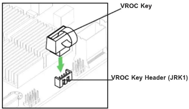
text_image
VROC Key VROC Key Header (JRK1)Disk-On-Module Power Connector
The Disk-On-Module (DOM) power connectors at JSD1 and JSD2 provide 5V power to a solid-state DOM storage devices connected to one of the SATA ports. Refer to the table below for pin definitions.
| DOM Power Pin Definitions | |
| Pin# Definition | |
| 1 5V | |
| 2 Ground | |
| 3 Ground | |
Power SMB (I²C) Header
The Power System Management Bus (I ^2 C) connector (JPI ^2 C1) monitors the power supply, fan, and system temperatures. Refer to the table below for pin definitions.
| Power SMB HeaderPin Definitions |
| Pin# Definition |
| 1 Clock |
| 2 Data |
| 3 PMBUS_Alert |
| 4 Ground |
| 5 +3.3V |
4-pin BMC External I²C Header
A System Management Bus header for BMC 2.0 is located at JIPMB1. Connect the appropriate cable here to use the IPMB I ^2 C connection on your system. Refer to the table below for pin definitions.
| External I2C Header Pin Definitions | |
| Pin# | Definition |
| 1 | Data |
| 2 | Ground |
| 3 | Clock |
| 4 | No Connection |
Chassis Intrusion
A Chassis Intrusion header is located at JL1 on the motherboard. Attach the appropriate cable from the chassis to inform you when the chassis is opened. Refer to the table below for pin definitions.
| Chassis Intrusion Pin Definitions | |
| Pin# Definition | |
| 1 Intrusion Input | |
| 2 Ground |
NVMe SMBus Headers
NVMe SMBus (fC) header (JNVI²C), used for PCIe SMBus clock and data connections, provides hot-plug support via a dedicated SMBus interface. This feature is only available for a Supermicro complete system with an SMCI-proprietary NVMe add-on card and a proper cable installed. Refer to the table below for pin definitions.
| NVMe SMBus Header Pin Definitions | |
| Pin# | Definition |
| 1 | Data |
| 2 | Ground |
| 3 | Clock |
| 4 | VCCIO |
PCIe 4.0 M.2 Slots
The X12DPG-QT6 motherboard has two PCIe 4.0 M.2 slots. M.2 allows for a variety of card sizes, increased functionality, and spatial efficiency. The M.2 slots on the motherboard support PCIe 4.0 x4 M.2 NVMe SSDs in the 2242, 2260, 2280, and 22110 form factors.
Inlet Sensor Header
This header (JSEN1) allows BMC to monitor thermal inlet temperature. A special module is required. Please contact Supermicro at www.supermicro.com to purchase the module for this header. Refer to the table below for pin definitions.
| Inlet Sensor HeaderPin Definitions | |
| Pin# | Definition |
| 1 | SMBDAT |
| 2 | Ground |
| 3 | SMBCLK |
| 4 | 3.3V STBY |
SlimSAS NVMe Connectors
Two SlimSAS NVMe connectors provide four NVMe connections (P1_NVME0/1, P1_NVME2/3). Use these NVMe connections to attach high-speed PCIe storage devices.
Note: When installing an NVMe device on a motherboard, please be sure to connect the first NVMe port (P1_NVME0/1) first for your system to work properly.
NCSI Connector
The NCSI header (JNCSI1) is used to connect a Network Interface Card (NIC) to the motherboard which will allow the onboard BMC (Baseboard Controller) to communicate with a network.
I-SATA 3.0 and S-SATA 3.0 Ports
The X12DPG-QT6 has eight I-SATA 3.0 ports (I-SATA0\~3, I-SATA4\~7) and two S-SATA ports (S-SATA4, S-SATA5) on the motherboard. These SATA ports are supported by the Intel® C621A chipset. S-SATA4 and S-SATA5 can be used with Supermicro SuperDOMs which are orange SATA DOM connectors with power pins built in, and do not require external power cables. S-SATA4 and S-SATA-5 are compatible with regular SATA HDDs or SATA DOMs that need external power cables.
SPDIF\_IN Header
The Sony/Philips Digital Interface (JSPDIF_IN1) header is used for digital audio. Place a cap on each header for audio support. A cable is needed to use the connection.
| SPDIF_InPin Definitions |
| Pin# Definition |
| 1 S/PDIF_In |
| 2 Ground |
4.3 Input/Output Ports
Rear I/O Ports
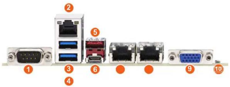
See the figure below for the locations and descriptions of the I/O ports on the rear of the motherboard.
text_image
Diagram of network equipment components with numbered labels pointing to different ports and connectorsFigure 4-2. Rear I/O Ports
| Rear I/O Ports | ||
| # Description # Description | ||
| 1 COM Port 1 6 USB5 (3.0) | ||
| 2 Dedicated BMC LAN 7 LAN1 | ||
| 3 USB2 (3.0) 8 LAN2 | ||
| 4 USB3 (3.0) 9 VGA Port | ||
| 5 USB4 (3.0) 10 UID Switch | ||
4.4 Jumpers
Explanation of Jumpers
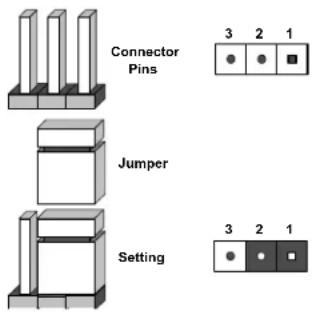
To modify the operation of the motherboard, jumpers can be used to choose between optional settings. Jumpers create shorts between two pins to change the function of the connector. Pin 1 is identified with a square solder pad on the printed circuit board. See the diagram below for an example of jumping pins 1 and 2. Refer to the motherboard layout page for jumper locations.
Note: On two-pin jumpers, "Closed" means the jumper is on and "Open" means the jumper is off the pins.
text_image
Connector Pins Jumper Setting 3 2 1 3 2 1CMOS Clear
JBT1 is used to clear CMOS, which will also clear any passwords. Instead of pins, this jumper consists of contact pads to prevent accidentally clearing the contents of CMOS.
To Clear CMOS

- First power down the system and unplug the power cord(s).
- Remove the cover of the chassis to access the motherboard and remove the battery from the motherboard.
- Short the CMOS pads with a metal object such as a small screwdriver for at least four seconds.
- Remove the screwdriver (or shorting device).
- Replace the cover, reconnect the power cord(s), and power on the system.
Note 1: Clearing CMOS will also clear all passwords.
Note 2: Do not use the PW_ON connector to clear CMOS.
LAN Port Enable/Disable
Jumper JPTG1 allows the user to enable the onboard LAN ports (LAN1 and LAN2). The default setting is pins 1-2 to enable the connections. Refer to the table below for jumper settings.
| LAN Enable/DisableJumper Settings | |
| Jumper Setting Definition | |
| Pins 1-2 Enable | |
| Pins 2-3 Disable | |
ME Recovery
JPME2 is used for ME Firmware Recovery mode, which will limit system resource for essential function use only without putting restrictions on power use. In the single operation mode, online upgrade will be available via Recovery mode. Refer to the table below for jumper settings.
| ME RecoveryJumper Settings | |
| Jumper Setting Definition | |
| Pins 1-2 Normal | (Default) |
| Pins 2-3 ME Recovery | |
HD Audio Enable
JHD_AC1 allows you to enable or disable the onboard high definition audio support. Refer to the table below for jumper settings
| HD Audio Enable/Disable Jumper Settings | |
| Jumper Setting Definition | |
| Open Enabled (Default) | |
| Short Disabled | |
Onboard Audio Enable
JPAC1 allows you to enable or disable the onboard audio support. The default position is on pins 1-2 to enable onboard audio connections. Refer to the table below for jumper settings.
| Audio Enable/Disable Jumper Settings |
| Jumper Setting Definition |
| Pins 1-2 Enabled (Default) |
| Pins 2-3 Disabled |
Watchdog
Watchdog (JWD1) is a system monitor that can reboot the system when a software application hangs. Close pins 1-2 to reset the system if an application hangs. Close pins 2-3 to generate a non-maskable interrupt (NMI) signal for the application that hangs. Refer to the table below for jumper settings. For this function to work properly, please also enable the Watchdog setting in the BIOS.
| WatchdogJumper Settings | |
| Jumper Setting Definition | |
| Pins 1-2 Reset | |
| Pins 2-3 NMI | |
| Open Disabled | |
I²C Bus for VRM
JVRM1 and JVRM2 allow the BMC or the PCH to access CPU and memory VRM controllers. Refer to the table below for jumper settings.
| VRMJumper Settings | |
| Jumper Setting Definition | |
| Pins 1-2 BMC (Default) | |
| Pins 2-3 PCH | |
4.5 LED Indicators
LAN LEDs
Two LAN ports (LAN1 and LAN2) are located on the rear I/O panel of the motherboard. Each Ethernet LAN port has two LEDs. The green LED indicates activity, while the other Link LED may be green, amber, or off to indicate the speed of the connection. Refer to the tables below for more information.
| LAN1/2 Activity LED (Right)LED State | |
| Color Status Definition | |
| Green Flashing Active | |
| LAN1/2 Link LED (Left)LED State |
| LED Color Definition |
| Green 10Gbps (X12DPi-NT only) |
| Yellow/Amber 1Gbps |
BMC LAN LEDs
In addition to LAN1 and LAN2, an BMC LAN is also located on the rear I/O panel. The amber LED on the right indicates activity, while the green LED on the left indicates the speed of the connection. Refer to the table below for more information.
| BMC LAN LEDs | ||
| Color/State Definition | ||
| Link (left) | Green: Solid | 100 Mbps |
| Amber: Solid | 1Gbps | |
| Activity (Right) Amber | Blinking Active | |
BMC LAN
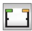
Activity LEDLink LED
Unit ID LED
A rear UID LED indicator (LED1) is located next to the UID switch on the motherboard. This UID indicator provides easy identification of a system unit that may need service.
| UID LEDLED Indicator | |
| LED Color Definition | |
| Blue: On Unit | Identified |
M.2 LEDs
Two M.2 LEDs are located at M2_1_LED1 and M2_2_LED1 on the motherboard. When the M.2 LED is blinking, M.2 functions normally. Refer to the table below for more information.
| M.2 LED State | |
| LED Color Definition | |
| Green: Blinking Device Working |
BMC Heartbeat LED
A BMC Heartbeat LED is located at LEDBMC on the motherboard. When LEDBMC is blinking, the BMC is functioning normally. Refer to the table below for more information.
| BMC Heartbeat LED Indicator | |
| LED Color Definition | |
| Green:Blinking | BMC Normal |
Chapter 5
Software
After the hardware has been installed, you can install the Operating System (OS), configure RAID settings and install the drivers.
5.1 Microsoft Windows OS Installation
If you will be using RAID, you must configure RAID settings before installing the Windows OS and the RAID driver. Refer to the RAID Configuration User Guides posted on our website at www.supermicro.com/support/manuals.
Installing the OS
- Create a method to access the MS Windows installation ISO file. That might be a DVD, perhaps using an external USB/SATA DVD drive, or a USB flash drive, or the BMC KVM console.
- Retrieve the proper RST/RSTe driver. Go to the Supermicro web page for your motherboard and click on "Download the Latest Drivers and Utilities", select the proper driver, and copy it to a USB flash drive.
- Boot from a bootable device with Windows OS installation. You can see a bootable device list by pressing F11 during the system startup.
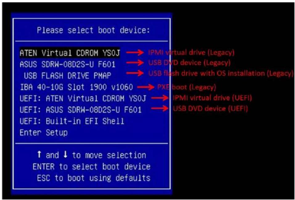
text_image
Please select boot device: ATEN Virtual CDROM YSOJ → IPMI virtual drive (Legacy) ASUS SDRW-08D2S-U F601 → USB DVD device (Legacy) USB FLASH DRIVE PMAP → USB flash drive with OS installation (Legacy) IBA 40-10G Slot 1900 v1060 → PXE boot (Legacy) UEFI: ATEN Virtual CDROM YSOJ → IPMI virtual drive (UEFI) UEFI: ASUS SDRW-08D2S-U F601 → USB DVD device (UEFI) UEFI: Built-in EFI Shell Enter Setup ↑ and ↓ to move selection ENTER to select boot device ESC to boot using defaultsFigure 5-1. Select Boot Device
- During Windows Setup, continue to the dialog where you select the drives on which to install Windows. If the disk you want to use is not listed, click on "Load driver" link at the bottom left corner.
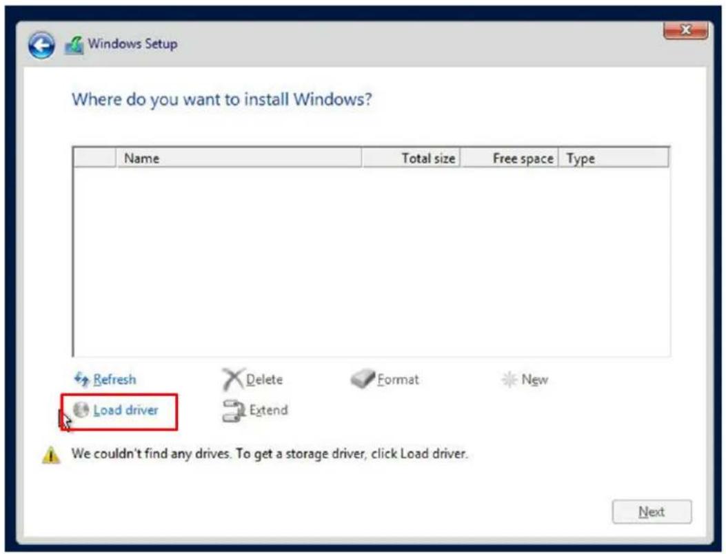
text_image
Where do you want to install Windows? Name Total size Free space Type Refresh Delete Format New Load driver Extend We couldn't find any drives. To get a storage driver, click Load driver. NextFigure 5-2. Load Driver Link
To load the driver, browse the USB flash drive for the proper driver files.
- For RAID, choose the SATA/sSATA RAID driver indicated then choose the storage drive on which you want to install it.
-
For non-RAID, choose the SATA/sSATA AHCI driver indicated then choose the storage drive on which you want to install it.
-
Once all devices are specified, continue with the installation.
- After the Windows OS installation has completed, the system will automatically reboot multiple times.
5.2 Driver Installation
The Supermicro website contains drivers and utilities for your system at https://www.supermicro.com/wdl. Some of these must be installed, such as the chipset driver.
After accessing the website, go into the CDR_Images (in the parent directory of the above link) and locate the ISO file for your motherboard. Download this file to a USB flash drive or a DVD. (You may also use a utility to extract the ISO file if preferred.)
Another option is to go to the Supermicro website at http://www.supermicro.com/products/. Find the product page for your motherboard, and "Download the Latest Drivers and Utilities". Insert the flash drive or disk and the screenshot shown below should appear.
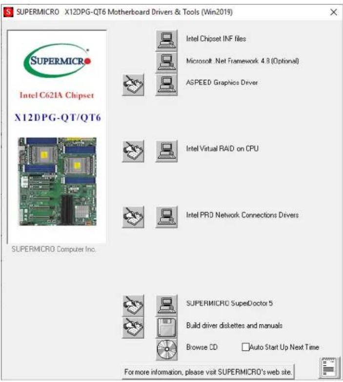
text_image
SUPERMICRO X12DPG-QT6 Motherboard Drivers & Tools (Win2019) Intel C621A Chipset X12DPG-QT/QT6 SUPERMICRO Computer Inc. Intel Chipset INF files Microsoft .Net Framework 4.8 (Optional) ASPEED Graphics Driver Intel Virtual RAD on CPU Intel PRO Network Connections Drivers SUPERMICRO SuperDoctor 5 Build driver diskettes and manuals Browse CD Auto Start Up Next Time For more information, please visit SUPERMICRO's web site.Figure 5-3. Driver & Tool Installation Screen
Note: Click the icons showing a hand writing on paper to view the readme files for each item. Click the computer icons to the right of these items to install each item (from top to the bottom) one at a time. After installing each item, you must re-boot the system before moving on to the next item on the list. The bottom icon with a CD on it allows you to view the entire contents.
5.3 SuperDoctor® 5
The Supermicro SuperDoctor 5 is a program that functions in a command-line or web-based interface for Windows and Linux operating systems. The program monitors such system health information as CPU temperature, system voltages, system power consumption, fan speed, and provides alerts via email or Simple Network Management Protocol (SNMP).
SuperDoctor 5 comes in local and remote management versions and can be used with Nagios to maximize your system monitoring needs. With SuperDoctor 5 Management Server (SSM Server), you can remotely control power on/off and reset chassis intrusion for multiple systems with SuperDoctor 5 or BMC. SuperDoctor 5 Management Server monitors HTTP, FTP, and SMTP services to optimize the efficiency of your operation.
SuperDoctor® Manual and Resources
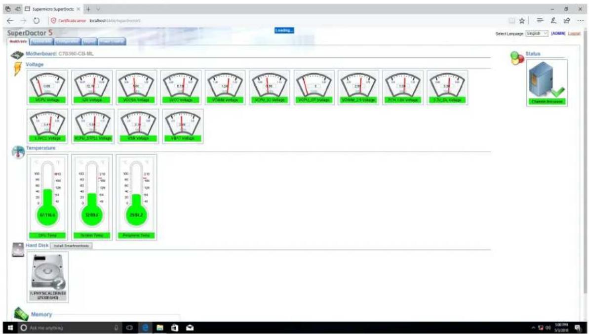
text_image
SuperDoctor S Matherboard: CT8360-CB-ML Voltage 120V 120V 120V 120V 120V 120V 120V 120V 120V 120V 120V 120V 120V 120V 120V 120V 120V 120V 120V 120V 120A 120A 120A 120A 120A 120A 120A 120A 120A 120A 120A 120A 120A 120A 120A 120A 120A 120A 120A 120A 120E 120E 120E 120E 120E 120E 120E 120E 120E 120E 120E 120E 120E 120E 120E 120E 120E 120E 120E 120E 120A 120A 120A 120A 120A 120A 120A 120A 120A 120A 120A 120A 120A 120A 120A 120A 120A 120A 120A 120B 120B 120B 120B 120B 120B 120B 120B 120B 120B 120B 120B 120B 120B 120B 120B 120B 120B 120B 120B 120C 120C 120C 120C 120C 120C 120C 120C 120C 120C 120C 120C 120C 120C 120C 120C 120C 120C 120C 120C 120D 120D 120D 120D 120D 120D 120D 120D 120D 120D 120D 120D 120DFigure 5-4. SuperDoctor 5 Interface Display Screen (Health Information)
5.4 BMC
The X12DPG-QT provides remote access, monitoring and management through the baseboard management controller (BMC) and other management controllers distributed among different system modules. There are several BIOS settings that are related to BMC.
For general documentation and information on BMC, visit our website at: https://www.supermicro.com/en/solutions/management-software/bmc-resources
BMC ADMIN User Password
For security, each system is assigned a unique default BMC password for the ADMIN user. This can be found on a sticker on the chassis and a sticker on the motherboard. The sticker also displays the BMC MAC address.
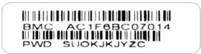
text_image
BMC AC1F6BC07014 PWD SUOKJKJYZCFigure 5-5. BMC Password Label
See Chapter 1 for the locations of the labels.
Chapter 6
Optional Components
This chapter describes optional system components and installation procedures.
6.1 Optional Parts List
| Optional Parts List | ||
| Description Part Number Quantity | ||
| Passive GPU Kit MCP-320-74702-0N-KIT 1 | ||
| Passive GPU Extender MCP-120-74703-0N | ||
| GPU Dummy Assembly MCP-240-00096-0N | ||
| HDD Converter MCP-220-93801-0B | ||
| Storage Control Card and Cable(s) | AOC-S3008L-L8i 1 | |
| CBL-SAST-1275-100 2 | ||
| AOC-S3108L-H8iR 1 | ||
| CBL-SAST-1275-100 2 | ||
| AOC-S3108L-H8iR-16DD 1 | ||
| CBL-SAST-1275-100 2 | ||
| Super Cap for LSI 3108 | BTR-TFM8G-LSICVM02 1 | |
| BKT-BBU-BRACKET-05 1 | ||
| NVMe Kit | AOC-SLG4-4E4T-O 1 | |
| CBL-SAST-1275-85 2 | ||
| MCP-220-00150-0B | 4 | |
| Intel VROC RAID Key | AOC-VROCINTMOD | 1 |
| AOC-VROCSTNMOD | 1 | |
| AOC-VROCPREMOD | 1 | |
| Mounting Rails | MCP-290-00059-0B | 1 |
| Front Bezel | MCP-210-74703-0B | 1 |
| TPM Security Module | AOM-TPM-9670V-S-O | 1 |
6.2 Passive GPU Support
These optional parts provide passive GPU support.
| Passive GPU Support | |||
| Part Number Description | Quantity GPU Configuration | ||
| MCP-320-74702-0N-KIT | X11 GPU Kit for passive GPU/Coprocessor support | 1 | GPU x4MCP-240-00096-0N |
| SC747B GPU / Add-on Card Dummy Assembly (2 Slots)-Single Pack | 0 | ||
| MCP-120-74703-0N | GPU long offset extender for A100 and MI100 | 4 | |
| MCP-320-74702-0N-KIT | X11 GPU Kit for passive GPU/Coprocessor support | 1 | GPU x3MCP-240-00096-0N |
| SC747B GPU / Add-on Card Dummy Assembly (2 Slots)-Single Pack | 1 | ||
| MCP-120-74703-0N | GPU long offset extender for A100 and MI100 | 3 | |
| MCP-320-74702-0N-KIT | X11 GPU Kit for passive GPU/Coprocessor support | 1 | GPU x2 |
| MCP-240-00096-0N | SC747B GPU / Add-on Card Dummy Assembly (2 Slots)-Single Pack | 1 | |
| MCP-120-74703-0N | GPU long offset extender for A100 and MI100 | 2 | |
| MCP-320-74702-0N-KIT | X11 GPU Kit for passive GPU/Coprocessor support | 1 | GPU x1MCP-240-00096-0N |
| SC747B GPU / Add-on Card Dummy Assembly (2 Slots)-Single Pack | 3 | ||
| MCP-120-74703-0N | GPU long offset extender for A100 and MI100 | 1 | |
6.3 Storage Control Card
| Storage Control Card | |||
| Item Part Number | Cable HDD Configuration | ||
| Storage Control Card | AOC-S3008L-L8iAOC-S3108L-H8iR-16DDAOC-S3108L-H8iR | CBL-SAST-1275-100 x2 SAS3 HDD x3 | |
| Storage Add-on Card | AOC-SLG4-4E4T | CBL-SAST-1276-85 x2 | NVMe x8 |
6.4 Intel Virtual RAID on CPU (VROC)
Intel® Virtual RAID on CPU (Intel VROC) is an enterprise RAID solution for NVMe SSDs directly attached to Intel Xeon Scalable processors. Intel Volume Management Device (VMD) is an integrated controller inside the CPU PCI-E root complex.
- A single processor supports up to 12 NVMe SSDs and up to 6 RAID arrays.
- A dual processor system supports up to 24 NVMe SSDs and 12 RAID arrays.
Strip sizes are 4K, 8K, 16K, 32K, 64K, 128K.
Requirements and Restrictions
- Intel VROC is only available when the system is configured for UEFI boot mode.
- To enable the mdadm command and support for RSTe, install the patch from
- Linux: https://downloadcenter.intel.com/download/28158/Intel-Virtual-RAID-on-CPU-Intel-VROC-and-Intel-Rapid-Storage-Technology-enterprise-Intel-RSTe-Driver-for-Linux-
- Windows: https://downloadcenter.intel.com/download/28108/Intel-Virtual-RAID-on-CPU-Intel-VROC-and-Intel-Rapid-Storage-Technology-enterprise-Intel-RSTe-Driver-for-Windows-
- To enable Intel VROC, a hardware key must be inserted on the motherboard, and the appropriate processor's Virtual Management Devices must be enabled in the BIOS setup.
- It is possible to enable Intel VROC without a hardware key installed, but only RAID0 will be enabled.
- Intel VROC is not compatible with secure boot. This feature must be disabled.
- When creating bootable OS RAID1 devices, you must have both devices on the same CPU, and a VMD on that CPU.
- Spanning drives when creating RAID devices is not recommended to due to performance issues, even though it is supported.
Supported SSDs and Operating Systems
To see the latest support information: https://www.intel.com/content/www/us/en/support/articles/000030310/memory-and-storage/ssd-software.html
Additional Information
Additional information is available on the product page for the Supermicro add-on card and the linked manuals.
www.supermicro.com/products/accessories/addon/AOC-VROCxxxMOD.cfm
Hardware Key
The Intel VROC hardware key is a license key that detects the Intel VROC SKU and activates the function accordingly. The key must be plugged into the Supermicro motherboard (connector JRK1). The key options are:
| Intel® VROC Keys | |||
| VROC Package Description Part Number Intel MM Number | |||
| Standard | RAID 0, 1, 10Supports 3rd party SSDs | AOC-VROCSTNMOD 951605 | |
| Premium | RAID 0, 1, 5, 10Supports 3rd party SSDs | AOC-VROCPREMOD 951606 | |
| Intel SSD only | RAID 0, 1, 5, 10Supports Intel SSDs only | AOC-VROCINTMOD 956822 | |
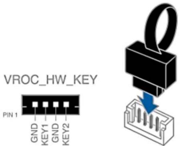
text_image
VROC_HW_KEY PIN 1 GND KEY1 GND KEY2Figure 6-1. Intel® VROC RAID Key and Motherboard Connector JRK1
Status Indications
An LED indicator on the drive carrier shows the RAID status of the drive.
| Drive Carrier Status LED Indicator | |
| Status State (red) | |
| Normal function Off | |
| Locating 4 Hz blink | |
| Fault Solid on | |
| Rebuilding 1 Hz Blink | |
IBPI SFF 8489 Defined Status LED States
Hot Swap Drives
Intel VMD enables hot-plug and hot-unplug for NVMe SSDs, whether from Intel or other manufacturers. Under vSphere ESXi, several steps are necessary to avoid potential stability issues. See the information at link [1] below.
Hot-unplug
- Prevent devices from being re-detected during rescan:
esxcli storage core claiming autoclaim --enabled=false
- Unmount the VMFS volumes on the device. Check [2] for details.
- Detach the device. Check [3] for details.
- Physically remove the device.
Hot-plug
• Physically install the device.
ESXi will automatically discover NVMe SSDs, but a manual scan may be required in some cases.
Related Information Links
[1] https://kb.vmware.com/s/article/2151404
[2] https://docs.vmware.com/en/VMware-vSphere/6.5/com.vmware.vsphere.storage.doc/GUID-1B56EF97-F60E-4F21-82A7-8F2A7294604D.html
[3] https://docs.vmware.com/en/VMware-vSphere/6.5/com.vmware.vsphere.storage.doc/GUID-F2E75F67-740B-4406-9F0C-A2D99A698F2A.html
6.5 TPM Security Module
SPI capable TPM 2.0 (or 1.2) with Infineon 9670 controller, Horizontal form factor
The JTPM1 header is used to connect a Trusted Platform Module (TPM). A TPM is a security device that supports encryption and authentication in hard drives. It enables the motherboard to deny access if the TPM associated with the hard drive is not installed in the system.
Details and installation procedures are at:
http://www.supermicro.com/manuals/other/TPM.pdf.
Chapter 7
Troubleshooting and Support
7.1 Information Resources
Website
A great deal of information is available on the Supermicro website, supermicro.com.

text_image
supermicro.com/en SUPERMICRO Menu Icon TECHNOLOGY & OUR PLANET Supermicro Resource-Saving Systems: Reduce Cost and Environmental ImpactFigure 7-1. Supermicro Website
- Specifications for servers and other hardware are available by clicking the menu icon, then selecting the Products option.
- The Support option offers downloads (manuals, BIOS/BMC, drivers, etc.), FAQs, RMA, warranty, and other service extensions.
Direct Links for the 740GP-TNRT System
Web SYS-740GP-TNRT specifications page
X12DPG-QT6 motherboard page for links to the Quick Reference Guide, User Manual, validated storage drives, etc.
BPN-SAS3-116A-N2 Backplane Manual
Direct Links for General Support and Information
Frequently Asked Questions
Add-on card descriptions
TPM User Guide
General Memory Configuration Guide: X12
Direct Links (continued)
BMC User Guide
SuperDoctor5 Large Deployment Guide
For validated memory, use our Product Resources page.
Product Matrices page for links to tables summarizing specs for systems, motherboards, power supplies, riser cards, add-on cards, etc.
Security Center for recent security notices
Supermicro Phone and Addresses
7.2 BMC Interface
The system supports a Baseboard Management Controller (BMC) interface. It provides remote access, monitoring and management. There are several BIOS settings related to the BMC.
For general documentation and information on the BMC, please visit our website at: www.supermicro.com/manuals/other/BMC_Users_Guide_X12_H12.pdf.

text_image
Dashboard System Component Info Health Event Log Configuration Remote Control Maintenance Advanced Settings Filter x Sensor specific x Threshold x Generic x OEM x Unspecified Health Event Log Clear Health Event Log Export to Excel Severity Data/Time Sensor Type Categories Description Event Type 2020-10-15 18:57:06 ACPowerOn [OEM] First AC Power on - Assertion Sensor-specific 2020-10-15 18:06:43 System NIC [OEM] Dedicated LAN Link Up - Assertion Sensor-specific 2020-10-15 17:41:37 ACPowerOn [OEM] First AC Power on - Assertion Sensor-specific 2020-10-15 17:41:17 System NIC [OEM] Dedicated LAN Link Up - Assertion Sensor-specific 2020-10-15 17:41:14 System NIC [OEM] Dedicated LAN Link Down - Assertion Sensor-specific 2020-10-15 17:41:12 System NIC [OEM] Dedicated LAN Link Up - Assertion Sensor-specificFigure 7-2. BMC Sample
7.3 Troubleshooting Procedures
Use the following procedures to troubleshoot your system. If you have followed all of the procedures below and still need assistance, refer to the Technical Support Procedures or Returning Merchandise for Service section(s) in this chapter. Power down the system before changing any non hot-swap hardware components.
No Power
- As you try to power up the system, note any beep codes. Refer to the next section for details on beep codes.
- Check that the BMC heartbeat LED on the motherboard is on.
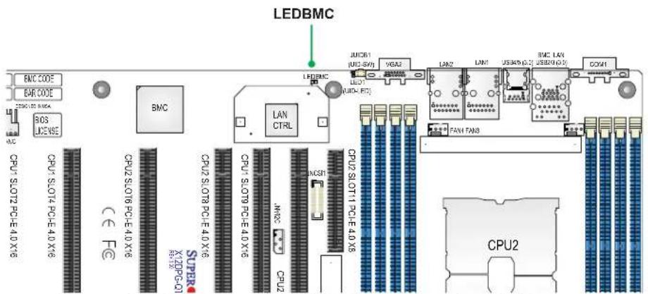
text_image
LEDBMC BMC CODE BAR CODE SOS JGENSE BMC LAN CTRL JUIC61 [UDI-SV] LED LEDBMC VGA2 LAN2 LAM USB40 (C:) BMC LAN USB20 (C:) COM1 CPU1.SLOT2.PCE-4.0.X/6 CPU2.SLOT4.PCE-4.0.X/6 CPU2.SLOT6.PCE-4.0.X/6 CPU2.SLOT8.PCE-4.0.X/6 CPU2.SLOT9.PCE-4.0.X/6 CPU2.SLOT11.PCE-4.0.X/6 CPU2.SLOT13.PCE-4.0.X/6 CPU2.SLOT14.PCE-4.0.X/6 CPU2.SLOT15.PCE-4.0.X/6 CPU2.SLOT16.PCE-4.0.X/6 CPU2.SLOT17.PCE-4.0.X/6 CPU2.SLOT18.PCE-4.0.X/6 CPU2.SLOT19.PCE-4.0.X/6 CPU2.SLOT20.PCE-4.0.X/6 CPU2.SLOT21.PCE-4.0.X/6 CPU2.SLOT22.PCE-4.0.X/6 CPU2.SLOT23.PCE-4.0.X/6 CPU2.SLOT24.PCE-4.0.X/6 CPU2.SLOT25.PCE-4.0.X/6 CPU2.SLOT26.PCE-4.0.X/6 CPU2.SLOT27.PCE-4.0.X/6 CPU2.SLOT28.PCE-4.0.X/6 CPU2.SLOT29.PCE-4.0.X/6 CPU2.SLOT30.PCE-4.0.X/6 CPU2.SLOT31.PCE-4.0.X/6 CPU2.SLOT32.PCE-4.0.X/6 CPU2.SLOT33.PCE-4.0.X/6 CPU2.SLOT34.PCE-4.0.X/6 CPU2.SLOT35.PCE-4.0.X/6 CPU2.SLOT36.PCE-4.0.X/6 CPU2.SLOT37.PCE-4.0.X/6 CPU2.SLOT38.PCE-4.0.X/6 CPU2.SLOT39.PCE-4.0.X/6 CPU2.SLOT40.PCE-4.0.X/6 CPU2.SLOT41.PCE-4.0.X/6 CPU2.SLOT42.PCE-4.0.X/6 CPU2.SLOT43.PCE-4.0.X/6 CPU2.SLOT44.PCE-4.0.X/6 CPU2.SLOT45.PCE-4.0.X/6 CPU2.SLOT46.PCE-4.0.X/6 CPU2.SLOT47.PCE-4.0.X/6 CPU2.SLOT48.PCE-4.0.X/6 CPU2.SLOT49.PCE-4.0.X/6 CPU2.SLOT50.PCE-4.0.X/6 CPU2.SLOT51.PCE-4.0.X/6 CPU2.SLOT52.PCE-4.0.X/6 CPU2.SLOT53.PCE-4.0.X/6 CPU2.SLOT54.PCE-4.0.X/6 CPU2.SLOT55.PCE-4.0.X/6 CPU2.SLOT56.PCE-4.0.X/6 CPU2.SLOT57.PCE-4.0.X/6 CPU2.SLOT58.PCE-4.0.X/6 CPU2.SLOT59.PCE-4.0.X/6 CPU2.SLOT60.PCE-4.0.X/6 CPU2.SLOT61.PCE-4.0.X/6 CPU2.SLOT62.PCE-4.0.X/6 CPU2.SLOT63.PCE-4.0.X/6 CPU2.SLOT64.PCE-4.0.X/6 CPU2.SLOT65.PCE-4.0.X/6 CPU2.SLOT66.PCE-4.0.X/6 CPU2.SLOT67.PCE-4.0.X/6 CPU2.SLOT68.PCE-4.0.X/6 CPU2.SLOT69.PCE-4.0.X/6 CPU2.SLOT70.PCE-4.0.X/6 CPU2.SLOT71.PCE-4.0.X/6 CPU2.SLOT72.PCE-4.0.X/6 CPU2.SLOT73.PCE-4.0.X/6 CPU2.SLOT74.PCE-4.0.X/6 CPU2.SLOT75.PCE-4.0.X/6 CPU2.SLOT76.PCE-4.0.X/6 CPU2.SLOT77.PCE-4.0.X/6 CPU2.SLOT78.PCE-4.0.X/6 CPU2.SLOT79.PCE-4.0.X/6 CPU2.SLOT80.PCE-4.0.X/6 CPU2.SLOT81.PCE-4.0.X/6 CPU2.SLOT82.PCE-4.0.X/6 CPU2.SLOT83.PCE-4.0.X/6 CPU2.SLOT84.PCE-4.0.X/6 CPU2.SLOT85.PCE-4.0.X/6 CPU2.SLOT86.PCE-4.0.X/6 CPU2.SLOT87.PCE-4.0.X/6 CPU2.SLOT88.PCE-4.0.X/6 CPU2.SLOT89.PCE-4.0.X/6 CPU2.SLOT90.PCE-4.0.X/6 CPU2.SLOT91.PCE-4.0.X/6 CPU2.SLOT92.PCE-4.0.X/6 CPU2.SLOT93.PCE-4.0.X/6 CPU2.SLOT94.PCE-4.0.X/6 CPU2.SLOT95.PCE-4.0.X/6 CPU2.SLOT96.PCE-4.0.X/6 CPU2.SLOT97.PCE-4.0.X/6 CPU2.SLOT98.PCE-4.0.X/6 CPU2.SLOT99.PCE-4.0.X/6 CPU2.SLOT100.PCE-4.0.X/6Figure 7-3. Location of the MB BMC Heartbeat LED
- Make sure that the power connector is connected to your power supply.
- Make sure that no short circuits exist between the motherboard and chassis.
- Disconnect all cables from the motherboard, including those for the keyboard and mouse.
- Remove all add-on cards.
- Install a CPU, a heatsink, connect the internal speaker (if applicable), and the power LED to the motherboard. Make sure that the heatsink is fully seated.
- Use the correct type of onboard CMOS battery as recommended by the manufacturer. Check to verify that it still supplies \~3VDC. If it does not, replace it with a new one. Warning: To avoid possible explosion, do not install the battery upside down.
- Verify that all jumpers are set to their default positions.
- Check that the power supplies' input voltage operate at 100-120v or 180-240v.
- Turn the power switch on and off to test the system.
No Video
- If the power is on but you have no video, remove all the add-on cards and cables.
- As you try to power up the system, note any beep codes. Refer to the next section for details on beep codes.
System Boot Failure
If the system does not display POST (Power-On-Self-Test) or does not respond after the power is turned on, check the following:
Turn on the system with only one DIMM module installed. If the system boots, check for bad DIMM modules or slots by following the Memory Errors Troubleshooting procedure below.
Memory Errors
- Make sure that the DIMM modules are properly and fully installed.
- Confirm that you are using the correct memory. Also, it is recommended that you use the same memory type and speed for all DIMMs in the system. See Section 3.3 for memory details.
- Check for bad DIMM modules or slots by swapping modules between slots and noting the results.
- Check the power supply voltage 115V/230V switch.
Losing the System's Setup Configuration
- Make sure that you are using a high quality power supply. A poor quality power supply may cause the system to lose the CMOS setup information.
- The battery on your motherboard may be old. Check to verify that it still supplies \~3VDC. If it does not, replace it with a new one.
- If the above steps do not fix the setup configuration problem, contact your vendor for repairs.
When the System Becomes Unstable
If the system becomes unstable during or after OS installation, check the following:
-
CPU/BIOS support: Make sure that your CPU is supported and that you have the latest BIOS installed in your system.
-
Memory support: Make sure that the memory modules are supported by testing the modules using memtest86 or a similar utility.
Note: Refer to the product page on our website at http://www.supermicro.com for memory and CPU support and updates.
- HDD support: Make sure that all hard disk drives (HDDs) work properly. Replace the bad HDDs with good ones.
- System cooling: Check the system cooling to make sure that all heatsink fans and CPU/system fans, etc., work properly. Check the hardware monitoring settings in the BMC to make sure that the CPU and system temperatures are within the normal range. Also check the front panel Overheat LED and make sure that it is not on.
- Adequate power supply: Make sure that the power supply provides adequate power to the system. Make sure that all power connectors are connected. Please refer to our website for more information on the minimum power requirements.
- Proper software support: Make sure that the correct drivers are used.
If the system becomes unstable before or during OS installation, check the following:
- Source of installation: Make sure that the devices used for installation are working properly, including boot devices such as CD.
- Cable connection: Check to make sure that all cables are connected and working properly.
- Using the minimum configuration for troubleshooting: Remove all unnecessary components (starting with add-on cards first), and use the minimum configuration (but with a CPU and a memory module installed) to identify the trouble areas. Refer to the steps listed in Section A above for proper troubleshooting procedures.
- Identifying bad components by isolating them: If necessary, remove a component in question from the chassis, and test it in isolation to make sure that it works properly. Replace a bad component with a good one.
- Check and change one component at a time instead of changing several items at the same time. This will help isolate and identify the problem.
- To find out if a component is good, swap this component with a new one to see if the system will work properly. If so, then the old component is bad. You can also install the component in question in another system. If the new system works, the component is good and the old system has problems.
7.4 BIOS Error Beep (POST) Codes
During the POST (Power-On Self-Test) routines, which are performed each time the system is powered on, errors may occur.
Non-fatal errors are those which, in most cases, allow the system to continue the boot-up process. The error messages normally appear on the screen.
Fatal errors are those which will not allow the system to continue the boot-up procedure. If a fatal error occurs, you should consult with your system manufacturer for possible repairs.
These fatal errors are usually communicated through a series of audible beeps. The table below lists some common errors and their corresponding beep codes encountered by users.
| BIOS Error Beep (POST) Codes | ||
| Beep Code Error | Message Description | |
| 1 short Refresh Circuits have been reset (Ready to power up) | ||
| 5 short, 1 long Memory error No memory detected in system | ||
| 5 long, 2 short Display memory read/write error Video adapter missing or with faulty memory | ||
| 1 long continuous System OH System overheat condition | ||
Additional BIOS POST Codes
The AMI BIOS supplies additional checkpoint codes, which are documented online at http://www.supermicro.com/support/manuals/ ("AMI BIOS POST Codes User's Guide").
When BIOS performs the Power On Self Test, it writes checkpoint codes to I/O port 0080h. If the computer cannot complete the boot process, a diagnostic card can be attached to the computer to read I/O port 0080h (Supermicro p/n AOC-LPC80-20).
For information on AMI updates, please refer to http://www.ami.com/products/.
7.5 Crash Dump Using the BMC Dashboard
In the event of a processor internal error (IERR) that crashes your system, you may want to provide information to support staff. You can download a crash dump of status information using the BMC Dashboard. The BMC manual is available at www.supermicro.com/manuals/other/BMC_Users_Guide_X12_H12.pdf.
Check Error Log
- Access the BMC web interface.
- Click the Server Health tab, then Event Log to verify an IERR error.
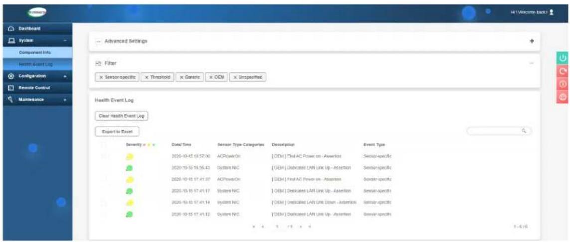
text_image
Dashboard System Component Info Harm Event Log Configuration Remote Control Maintenance Advanced Settings Filter x Sensor-specific x Threshold x Generic x OEM x Unspecified Health Event Log Clear Health Event Log Export to Excel Severity = 0 Date/Time Sensor Type Categories Description Event Type 2026-10-15 18:57:06 ACPowerOn [OEM] First AC Power on - Assertion Sensor-specific 2026-10-15 18:56:43 System NIC [OEM] Dedicated LAN Link Up - Assertion Sensor-specific 2026-10-15 17:41:37 ACPowerOn [OEM] First AC Power on - Assertion Sensor-specific 2026-10-15 17:41:17 System NIC [OEM] Dedicated LAN Link Up - Assertion Sensor-specific 2026-10-15 17:41:14 System NIC [OEM] Dedicated LAN Link Down - Assertion Sensor-specific 2026-10-15 17:41:12 System NIC [OEM] Dedicated LAN Link Up - Assertion Sensor-specific x 4 x 5 x 6 x 7 x 8 x 9 x 10 x 11 x 12 x 13 x 14 x 15 x 16 x 17 x 18 x 19 x 20 x 21 x 22 x 23 x 24 x 25 x 26 x 27 x 28 x 29 x 30 x 31 x 32 x 33 x 34 x 35 x 36 x 37 x 38 x 39 x 40 x 41 x 42 x 43 x 44 x 45 x 46 x 47 x 48 x 49 x 50 x 51 x 52 x 53 x 54 x 55 x 56 x 57 x 58 x 59 x 60 x 61 x 62 x 63 x 64 x 65 x 66 x 67 x 68 x 69 x 70 x 71 x 72 x 73 x 74 x 75 x 76 x 77 x 78 x 79 x 80 x 81 x 82 x 83 x 84 x 85 x 86 x 87 x 88 x 89 x 90 x 91 x 92 x 93 x 94 x 95 x 96 x 97 x 98 x 99 x 100 x - € / €Figure 7-4. BMC Event Log
In the event of an IERR, the BMC executes a crash dump. You must download the crash dump and save it.
7.6 UEFI BIOS Recovery
Warning: Do not upgrade the BIOS unless your system has a BIOS-related issue. Flashing the wrong BIOS can cause irreparable damage to the system. In no event shall Supermicro be liable for direct, indirect, special, incidental, or consequential damages arising from a BIOS update. If you do update the BIOS, do not shut down or reset the system while the BIOS is updating to avoid possible boot failure.
Overview
The Unified Extensible Firmware Interface (UEFI) provides a software-based interface between the operating system and the platform firmware in the pre-boot environment. The UEFI specification supports an architecture-independent mechanism that will allow the UEFI OS loader stored in an add-on card to boot the system. The UEFI offers clean, hands-off management to a computer during system boot.
Recovering the UEFI BIOS Image
A UEFI BIOS flash chip consists of a recovery BIOS block and a main BIOS block (a main BIOS image). The recovery block contains critical BIOS codes, including memory detection and recovery codes for the user to flash a healthy BIOS image if the original main BIOS image is corrupted. When the system power is turned on, the recovery block codes execute first. Once this process is complete, the main BIOS code will continue with system initialization and the remaining POST (Power-On Self-Test) routines.
Note 1: Follow the BIOS recovery instructions below for BIOS recovery when the main BIOS block crashes.
Note 2: When the BIOS recovery block crashes, you will need to follow the procedures to make a Returned Merchandise Authorization (RMA) request. Also, you may use the Supermicro Update Manager (SUM) Out-of-Band (https://www.supermicro.com.tw/products/nfo/SMS_SUM.cfm) to reflash the BIOS.
Recovering the Main BIOS Block with a USB Device
This feature allows the user to recover the main BIOS image using a USB-attached device without additional utilities used. A USB flash device such as a USB Flash Drive, or a USB CD/DVD ROM/RW device can be used for this purpose. However, a USB Hard Disk drive cannot be used for BIOS recovery at this time.
The file system supported by the recovery block is FAT (including FAT12, FAT16, and FAT32) which is installed on a bootable or non-bootable USB-attached device. However, the BIOS might need several minutes to locate the SUPER.ROM file if the media size becomes too large due to the huge volumes of folders and files stored in the device.
To perform UEFI BIOS recovery using a USB-attached device, follow the instructions below.
- Using a different machine, copy the "Super.ROM" binary image file into the Root "\" directory of a USB device or a writable CD/DVD.
Note 1: If you cannot locate the "Super.ROM" file in your drive disk, visit our website at www.supermicro.com to download the BIOS package. Extract the BIOS binary image into a USB flash device and rename it "Super.ROM" for the BIOS recovery use.
Note 2: Before recovering the main BIOS image, confirm that the "Super.ROM" binary image file you download is the same version or a close version meant for your motherboard.
-
Insert the USB device that contains the new BIOS image ("Super.ROM") into your USB drive and reset the system when the following screen appears.
-
After locating the healthy BIOS binary image, the system will enter the BIOS Recovery menu as shown below.
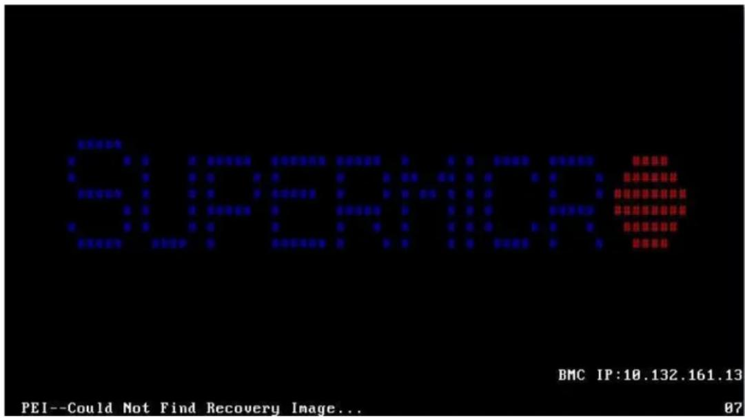
text_image
SUPERIOR BMC IP:10.132.161.13 PEI--Could Not Find Recovery Image... 07Note: At this point, you may decide if you want to start the BIOS recovery. If you decide to proceed with BIOS recovery, follow the procedures below.
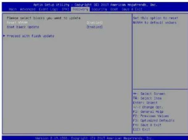
text_image
Aptio Setup Utility - Copyright (C) 2017 American Megatrends, Inc. Main Advanced Event Loss [PWI] Recovery Security Boot Save a Exit Please select blocks you want to update Boot (View [Enabled] Boot Block Update [Enabled] ►Proceed with flash update Set this option to reset NWMV to default values +: Select Screen T4: Select Item Enter: Select +/-F Change Out. F1: General Help F2: Previous Values F3: Optimized Defaults F4: Save & Exit ESC: Exit Version 2.19.1766. Copyright (C) 2017 Newles: Nestrends, Inc.- When the screen as shown above displays, use the arrow keys to select the item "Proceed with flash update" and press the
key. You will see the BIOS recovery progress as shown in the screen below.
Note: Do not interrupt the BIOS flashing process until it has completed.
- After the BIOS recovery process is complete, press any key to reboot the system.
- Using a different system, extract the BIOS package into a USB flash drive.
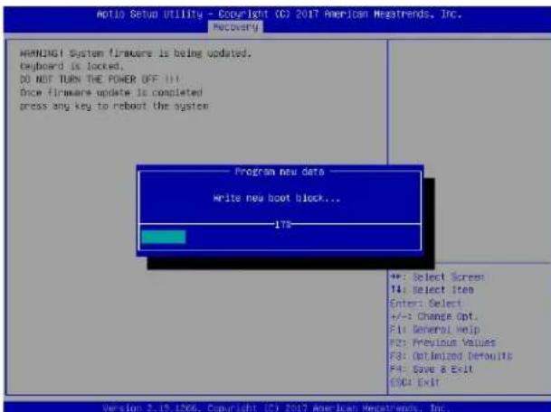
text_image
Aotio Setup Utility - Copyright (C) 2017 American Megatrends, Inc. WARNING System firmware is being updated. Keyboard is locked. DO NOT TURN THE POWER OFF Once firmware update is completed press any key to reboot the system Program new data Write new boot block... 178 +: Select Screen T4: Select item Enter: Select +/-: Change Opt. F1: General Help F2: Previous Values F3: Optimized Defaults F4: Save a Exit ESC: Exit Version 2.19.1266. Copyright (C) 2017 American Megatrends, Inc.- Press
continuously during system boot to enter the BIOS Setup utility. From the top of the tool bar, select Boot to enter the submenu. From the submenu list, select Boot Option
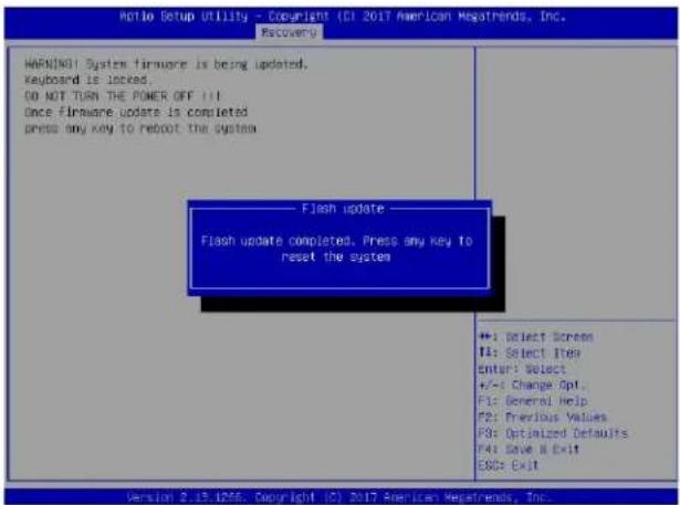
text_image
Ratio Setup Utility - Copyright (CI 2017 American Megatrends, Inc. Recovery WARNINOT System firmware is being updated. Keyboard is locked... DO NOT THAN THE POWER OFF !!! Once firmware update is completed press any key to reboot the system Flash update —— Flash update completed. Press any key to reset the system +: Select Screen I: Select Item Enter: Select +/-: Change Opt. F1: General Help F2: Previous Values F3: Optimized Defaults F4: Save All Exit ESC: Exit Version 2.15.1256. Copyright (C) 2017 American Megatrends, Inc.1 as shown below. Then, set Boot Option #1 to [UEFI AP:UEFI: Built-in EFI Shell]. Press to save the settings and exit the BIOS Setup utility.
- When the UEFI Shell prompt appears, type fs# to change the device directory path. Go to the directory that contains the BIOS package you extracted earlier from Step 6. Enter flash. nsh BIOSname.### at the prompt to start the BIOS update process.
![Supermicro SYS-740GP-TNRT - as shown below. Then, set Boot Option #1 to [UEFI AP:UEFI: Built-in EFI Shell]. Press to save the settings and exit the BIOS Setup utility. - 1](/content/2026/05/820779/images/53944169a9b511e2dda317f27cfd4c0bb623500dee6efe103dce2933ef8c1c21.jpg)
text_image
Auto Setup Utility - Copyright (C) 2017 American Megatrends, Inc. Main Advanced Event Loss IPMS Security Boot Save & Exit Boot Configuration Boot mode select [DUAL] LEGACY to EPI Support [Disabled] FIXED BOOT ORDER Priorities Boot Option #3 [DEFI: HP/DEFI: Bus...] Boot Option #2 [CD/DVD] Boot Option #3 [USB Hard Disk] Boot Option #4 [USB CD/DVD] Boot Option #5 [USB Key/SanOSK] Boot Option #6 [USB Floppy] Boot Option #7 [USB Lan] Boot Option #8 [Network: IBM QE SI...] Boot Option #9 [DEFI Hard Disk] Boot Option #10 [DEFI CD/DVD] Boot Option #11 [DEFI USB Hard Disk] Boot Option #12 [DEFI USB CO/DVD] Boot Option #13 [DEFI USB Key/DEFI...] Boot Option #14 [DEFI USB Floppy] Boot Option #15 [DEFI USB Lan] Boot Option #16 [DEFI Network] Boot Option #17 [Hard Disk] Add New Boot Option Sets the system boot order +: Select Screen T4: Select Item Enter: Select +/-: Change Out, F1: General help F2: Previous Values F3: Optimized Defaults F4: Save & Exit ESC: Exit Version 2.19.136, Copyright (C) 2017 American Megatrends, Inc.Note: Do not interrupt this process until the BIOS flashing is complete.
![Supermicro SYS-740GP-TNRT - as shown below. Then, set Boot Option #1 to [UEFI AP:UEFI: Built-in EFI Shell]. Press to save the settings and exit the BIOS Setup utility. - 2](/content/2026/05/820779/images/38e92a5499637687b1fad082813817410512c6a3c5b2370dbc8339860fc7ffe8.jpg)
text_image
LEFI Interactive Shell v2.1 ESK 11 LEFI v2.50 (American Regatrends, 0x0089XXC) Mapping table: F5D: A106(0):H0D(F0):BLK1; PcJW001(0x0)/PcI(0x14,0x0)/US$0x11,0x0)/H011_MER_0xG7901D2_0xB06,0x1 OR3532) BLK0: B106(0): PcJW001(0x0)/PcI(0x14,0x0)/US$0x11,0x0) Press ESR is 1 seconds to skb startup.msh or any other key to continue. Shell (fd) F5D:\ CD BLKOS F5D:VAFUOOS> CD SKAPME2_0362017 F5D:VAFUOOS\SKAPME2_0362017\ flash.nsh X13P07.5X- The screen above indicates that the BIOS update process is complete. When you see the screen above, unplug the AC power cable from the power supply, clear CMOS, and plug
![Supermicro SYS-740GP-TNRT - as shown below. Then, set Boot Option #1 to [UEFI AP:UEFI: Built-in EFI Shell]. Press to save the settings and exit the BIOS Setup utility. - 3](/content/2026/05/820779/images/39089f982d9b4e2bdd6f5d7a071e7c0653d470c05948b509a0f8d4d5ef090129.jpg)
the AC power cable in the power supply again to power on the system.
- Press
continuously to enter the BIOS Setup utility.
![Supermicro SYS-740GP-TNRT - as shown below. Then, set Boot Option #1 to [UEFI AP:UEFI: Built-in EFI Shell]. Press to save the settings and exit the BIOS Setup utility. - 4](/content/2026/05/820779/images/91362a640e729159f059fe94b45cc84e3b0f83f74afb083395b1b9021d9bc741.jpg)
text_image
Verifying HSB Block ....... done - Update success for FSK - Update success for SE. - Successful Update Recovery Loader to (PRx!! - Successful Update MFSB11- - Successful Update FSM11- - Successful Update NFK, [081 and 19021] - Successful Update FLOD and UTOX!! - ML entire image update success!! WALVING : System must power-off to have the changes take effect! Moving FS01:AFUD00S/SKJPME2_03162017/40x64,efi -> FS01:AFUD00S/SKJPME2_03162017/f df.sac - [ok] Moving FS01:AFUD00S/SKJPME2_03162017/aufemfix4,efi -> FS01:AFUD00S/SKJPME2_03162017 ?afuefu1.sac - [ok] ****************************************************************************************** * * Please ignore this 'Shell cannot read from file - device error' * Warning message due to it does not impact flashing process. * ****************************************************************************************** Routing * Delete successful. FSK->- Press
to load the default settings. - After loading the default settings, press
to save the settings and exit the BIOS Setup utility.
7.7 CMOS Clear
JBT1 is used to clear CMOS, which will also clear any passwords. Instead of pins, this jumper consists of contact pads to prevent accidentally clearing the contents of CMOS.
To Clear CMOS
- First power down the system completely.
- Remove the cover of the chassis to access the motherboard.
- Remove the onboard battery from the motherboard.
- Short the CMOS pads with a metal object such as a small screwdriver for at least four seconds.
- Remove the screwdriver or shorting device.
- Replace the cover, reconnect the power cords and power on the system.
Notes: Clearing CMOS will also clear all passwords.
Do not use the PW_ON connector to clear CMOS.

JBT1 contact pads
7.8 BMC Reset
The BMC can be reset using the UID button.
- Reset – Press and hold the button. After six seconds, the LED blinks at 2Hz. The BMC resets and the reset duration is \~250 ms. Then the BMC starts to boot.
- Restore factory default configuration – Hold the button for twelve seconds. The LED blinks at 4Hz while the defaults are configured. Note: All BMC settings including username and password will be removed except the FRU and network settings.
Firmware update – When the BMC firmware is being updated, the UID LED blinks at 10Hz.
| BMC Reset Options | ||
| Event UID LED | BMC Heartbeat LED | |
| Reset Blue, Blinks at 2Hz Green, solid | ||
| Restore Defaults | Blue, Blinks at 4Hz Off | |
| Update Blue, Blinks at 10Hz | ||
7.9 Where to Get Replacement Components
If you need replacement parts for your system, to ensure the highest level of professional service and technical support, purchase exclusively from our Supermicro Authorized Distributors/System Integrators/Resellers. A list can be found at: http://www.supermicro.com. Click the "Where to Buy" tab.
7.10 Reporting an Issue
Technical Support Procedures
Before contacting Technical Support, please take the following steps. If your system was purchased through a distributor or reseller, please contact them for troubleshooting services. They have the best knowledge of your specific system configuration.
- Please review the Troubleshooting Procedures in this manual and Frequently Asked Questions on our website before contacting Technical Support.
- BIOS upgrades can be downloaded from our website. Note: Not all BIOS can be flashed depending on the modifications to the boot block code.
-
If you still cannot resolve the problem, include the following information when contacting us for technical support:
-
System, motherboard, and chassis model numbers and PCB revision number
- BIOS release date/version (this can be seen on the initial display when your system first boots up)
- System configuration
An example of a Technical Support form is posted on our website. Distributors: For immediate assistance, please have your account number ready when contacting our technical support department by email.
Returning Merchandise for Service
A receipt or copy of your invoice marked with the date of purchase is required before any warranty service will be rendered. You can obtain service by calling your vendor for a Returned Merchandise Authorization (RMA) number. When returning to the manufacturer, the RMA number should be prominently displayed on the outside of the shipping carton, and mailed prepaid or hand-carried. Shipping and handling charges will be applied for all orders that must be mailed when service is complete.
For faster service, RMA authorizations may be requested online (http://www.supermicro.com/support/rma/).
Whenever possible, repack the chassis in the original Supermicro carton, using the original packaging material. If these are no longer available, be sure to pack the chassis securely, using packaging material to surround the chassis so that it does not shift within the carton and become damaged during shipping.
This warranty only covers normal consumer use and does not cover damages incurred in shipping or from failure due to the alteration, misuse, abuse or improper maintenance of products.
During the warranty period, contact your distributor first for any product problems.
Vendor Support Filing System
For issues related to Intel, use the Intel IPS filing system:
https://www.intel.com/content/www/us/en/design/support/ips/training/welcome.html
For issues related to Red Hat Enterprise Linux, since it is a subscription based OS, contact your account representative.
7.11 Feedback
Supermicro values your feedback as we strive to improve our customer experience in all facets of our business. Please email us at documentfeedback@supermicro.com to provide feedback on our manuals.
7.12 Contacting Supermicro
Headquarters
Address: Super Micro Computer, Inc.
980 Rock Ave.
San Jose, CA 95131 U.S.A.
Tel: +1 (408) 503-8000
Fax: +1 (408) 503-8008
Email: marketing@supermicro.com (General Information)
support@supermicro.com (Technical Support)
Website: www.supermicro.com
Europe
Address: Super Micro Computer B.V.
's-Hertogenbosch, The Netherlands
Tel: +31 (0) 73-6400390
Fax: +31 (0) 73-6416525
Email: sales@supermicro.nl (General Information)
support@supermicro.nl (Technical Support)
rma@supermicro.nl (Customer Support)
Website: www.supermicro.nl
Asia-Pacific
Address: Super Micro Computer, Inc.
3F, No. 150, Jian 1st Rd.
Zhonghe Dist., New Taipei City 235
Taiwan (R.O.C)
Tel: +886-(2) 8226-3990
Fax: +886-(2) 8226-3992
Email: support@supermicro.com.tw
Website: www.supermicro.com.tw
Appendix A
Standardized Warning Statements for AC Systems
About Standardized Warning Statements
The following statements are industry standard warnings, provided to warn the user of situations which have the potential for bodily injury. Should you have questions or experience difficulty, contact Supermicro's Technical Support department for assistance. Only certified technicians should attempt to install or configure components.
Read this appendix in its entirety before installing or configuring components in the Supermicro chassis.
These warnings may also be found on our website at http://www.supermicro.com/about/policies/safety_information.cfm.
Warning Definition

Warning! This warning symbol means danger. You are in a situation that could cause bodily injury. Before you work on any equipment, be aware of the hazards involved with electrical circuitry and be familiar with standard practices for preventing accidents.
警告の定義
この警告サインは危険を意味します。
Installation Instructions

Warning! Read the installation instructions before connecting the system to the power source.
設置手順書
Warning! This product relies on the building's installation for short-circuit (overcurrent) protection. Ensure that the protective device is rated not greater than: 250 V, 20 A.
サーキット・ブレーカー
Power Disconnection Warning

Warning! The system must be disconnected from all sources of power and the power cord removed from the power supply module(s) before accessing the chassis interior to install or remove system components.

text_image
CAUTION: This unit has redundant power sources. Please disconnect all the power cords before servicing.電源切断の警告
Equipment Installation

Warning! Only trained and qualified personnel should be allowed to install, replace, or service this equipment.
機器の設置
Warning! This unit is intended for installation in restricted access areas. A restricted access area can be accessed only through the use of a special tool, lock and key, or other means of security. (This warning does not apply to workstations).
アクセス制限区域
Warning! There is the danger of explosion if the battery is replaced incorrectly. Replace the battery only with the same or equivalent type recommended by the manufacturer. Dispose of used batteries according to the manufacturer's instructions
電池の取り扱い
Redundant Power Supplies

Warning! This unit might have more than one power supply connection. All connections must be removed to de-energize the unit.
冗長電源装置
Warning! Hazardous voltage or energy is present on the backplane when the system is operating. Use caution when servicing.
バックプレーンの電圧
Comply with Local and National Electrical Codes

Warning! Installation of the equipment must comply with local and national electrical codes.
地方および国の電気規格に準拠
Warning! Ultimate disposal of this product should be handled according to all national laws and regulations.
製品の廃棄
Warning! Hazardous moving parts. Keep away from moving fan blades. The fans might still be turning when you remove the fan assembly from the chassis. Keep fingers, screwdrivers, and other objects away from the openings in the fan assembly's housing.
ファン・ホットスワップの警告
Power Cable and AC Adapter

Warning! When installing the product, use the provided or designated connection cables, power cables and AC adaptors. Using any other cables and adaptors could cause a malfunction or a fire. Electrical Appliance and Material Safety Law prohibits the use of UL or CSA-certified cables (that have UL/CSA shown on the cord) for any other electrical devices than products designated by Supermicro only.
電源コードとACアダプター
System Specifications
Processors
Dual 3rd Gen Intel® Xeon® Scalable processors in dual Socket LGA-4189 (Socket P+) sockets; UPI up to 11.2GB/s; support CPU TDP 270W Note: Refer to the motherboard specifications pages on our website for updates to supported processors.
Chipset
Intel® C621A
BIOS
AMI 32Mb SPI Flash ROM
Memory
Supports up to 4 TB of 3DS LRDIMM/LRDIMM/3DS RDIMM/RDIMM DDR4 (288-pin) ECC memory with speeds of 3200 MHz in 16 memory slots and up to 4 TB of Intel® Optane™ PMem 200 Series with speeds of up to 3200 MHz.
SATA Controller
On-chip (Intel® C621A) Controller
Drive Bays
Eight hot-swap 3.5" drive bays
PCI Expansion Slots
Four PCI Express 4.0 x16 slots (Priority to GPU) Two PCI Express 4.0 x16 LP slots One PCI Express 4.0 x8
Input/Output
Network: Two LAN ports BMC: Dedicated LAN port USB: Six USB 3.0 ports—4 rear, 2 front, 1 Type A Video : One VGA port Serial: One serial header
Motherboard
X12DPG-QT6; 15.12" (W) x 13.2" (L) ATX (384.05 mm x 335.28 mm)
Chassis
CSE-747BTS-R2K20BP; 4U Rackmount/Tower, 7.0 x 18.2 x 26.5 in. / 178 x 462 x 673 mm. (W x H x D)
System Cooling
Four heavy duty fans Two rear exhaust fans TWo CPU cooling modules Two optional fans for passive GPUs
Power Supply
Model: 2200W Titanium Level efficiency redundant power supply
Rated Input Current: 14A (100V) to 11A (240V)
Rated Input Frequency: 50-60 Hz
Rated Output Power: 2200W
Rated Output Voltages: +12V (183.3A), +5Vsb (6A)
Operating Environment
Operating Temperature: 10° to 35° C (50° to 95° F)
Non-operating Temperature: -40° to 60° C (-40° to 140° F)
Operating Relative Humidity: 8% to 90% (non-condensing)
Non-operating Relative Humidity: 5% to 95% (non-condensing)
Regulatory Compliance
FCC, ICES, CE, UKCA, VCCI, RCM, NRTL, CB
Applied Directives, Standards
EMC/EMI: 2014/30/EU (EMC Directive)
Electromagnetic Compatibility Regulations 2016
FCC Part 15 Subpart B
ICES-003
VCCI-CISPR 32
AS/NZS CISPR 32
BS/EN 55032
BS/EN 55035
CISPR 32
CISPR 24/CISPR 35
BS/EN 61000-3-2
BS/EN 61000-3-3
BS/EN 61000-4-2
BS/EN 61000-4-3
BS/EN 61000-4-4
BS/EN 61000-4-5
BS/EN 61000-4-6
BS/EN 61000-4-8
BS/EN 61000-4-11
Product Safety: 2014/35/EU (LVD Directive)
UL/CSA 60950-1 & 62368-1 (USA and Canada)
Electrical Equipment (Safety) Regulations 2016
IEC/BS/EN 60950-1 & 62368-1
Environment:
2011/65/EU (RoHS Directive)
EC 1907/2006 (REACH)
2012/19/EU (WEEE Directive)
California Proposition 65
Perchlorate Warning
California Best Management Practices Regulations for Perchlorate Materials: This Perchlorate warning applies only to products containing CR (Manganese Dioxide) Lithium coin cells. "Perchlorate Material-special handling may apply. See www.dtsc.ca.gov/hazardouswaste/perchlorate"
Appendix C
BSMI
物質含有情況標示聲門書
Declaration of the Presence Condition of the Restricted Substances Marking
| 設備名稱:超及工作站/SuperWorkstation 型號(型式):747-R22X12Equipment name Type designation (Type)(系列型號:747-22,SYS-740GP-TNRT) | ||||||
| 單元Unit | 眼*拓質及其化學符號Restricted substances and its chemical symbols | |||||
| 鉛Lead(Pb) | 天Mercury(Hg) | 鎘Cadmium(Cd) | 六億鉻Hexavalent chromium( Cr^16 ) | 多溴聯苯Polybrominated biphenyls(PBB) | 多溴二苯醚Polybrominated diphenyl ethers(PBDE) | |
| 機殼(Chassis) | ○ | ○ | ○ | ○ | ○ | ○ |
| 機殼風扇(Chassis Fan) | - | ○ | ○ | ○ | ○ | ○ |
| 線材(Cable) | ○ | ○ | ○ | ○ | ○ | ○ |
| 主機板(Motherboard) | - | ○ | ○ | ○ | ○ | ○ |
| 電源供應器(Power Supply) | - | ○ | ○ | ○ | ○ | ○ |
| 硬碟(HDD) | - | ○ | ○ | ○ | ○ | ○ |
| 電源背板(PDB) | - | ○ | ○ | ○ | ○ | ○ |
| 附加卡(Add-on Card) | - | ○ | ○ | ○ | ○ | ○ |
| 備考1.“超出0.1 wt %”及“超出0.01 wt %”係指眼*拓質之百分比含量超出百分比含量基準值。Note 1:“Exceeding 0.1 wt %”and“exceeding 0.01 wt %”indicate that the percentage content of the restricted substance exceeds the reference percentage value of presence condition.備考2.“○”係指該項眼*拓質之百分比含量未超出百分比含量基準值。Note 2:“○”indicates that the percentage content of the restricted substance does not exceed the percentage of reference value of presence.備考3.“-”係指該項眼*拓質為排除項目。Note 3:The “-”indicates that the restricted substance corresponds to the exemption. | ||||||
輸入額定:
100-127Vac, 60-50Hz, 12-11A (X2)
200-240Vac, 60-50Hz, 10-9.5A (X2)
BUREAU OF STANDARDS, METROLOGY AND INSPECTION,
MINISTRY OF ECONOMIC AFFAIRS
商品驗證登錄電子證書
CERTIFICATE OF THE REGISTRATION OF PRODUCT CERTIFICATION

for Registration of Product
The application made by
Certification has been reviewed and found to be in compliance with related regulations. Therefore, registration is granted with the
Product Safety Mark and the Identification No.
R36199
. Details of the registration are follows :
申請人:美超微電腦股份有限公司
統一編號:12729477
Applicant
Uniform No.
地址:新北市中和區建一路150號3樓
Address
生產廠場:詳如附表
Factory
廠址:詳如附表
Factory Address
商品種類名稱:
Type/name of product
This certificate is issued by the BSMI. (No.4, Sec. 1, Jinan Rd., Zhongzheng Dist., Taipei City 100, Taiwan)
BUREAU OF STANDARDS, METROLOGY AND INSPECTION,
MINISTRY OF ECONOMIC AFFAIRS
商品驗證登錄電子證書
CERTIFICATE OF THE REGISTRATION OF PRODUCT CERTIFICATION
Factory : 3F., No. 306, Changan St., Bade District, Taoyuan City 33463, Taiwan
- SUPER MICRO COMPUTER, INC. TAIWAN
No. 1899, Xingfeng Road, Da An Vil, Bade District,
Taoyuan City 33463, Taiwan
- SUPER MICRO COMPUTER B.V.