
DVR-4TL - Security Camera Speco Technologies - Free user manual and instructions
Find the device manual for free DVR-4TL Speco Technologies in PDF.


User questions about DVR-4TL Speco Technologies
0 question about this device. Answer the ones you know or ask your own.
Ask a new question about this device
Download the instructions for your Security Camera in PDF format for free! Find your manual DVR-4TL - Speco Technologies and take your electronic device back in hand. On this page are published all the documents necessary for the use of your device. DVR-4TL by Speco Technologies.
USER MANUAL DVR-4TL Speco Technologies
Caution and Preventive Tips
• Take care not to drop the unit or subject the unit to major shocks or jolts.
- Do not place this unit on an unstable stand, bracket or mount.
- This unit is designed for indoor use only. Do not place the unit near water or in other extremely humid conditions.
- This unit should not be placed in a built-in installation unless proper ventilation is provided.
- Please check the used type of power source before you plug and operate the unit; AC100V \~AC240V is acceptable.
- If the clearing is necessary, note to plug the unit from the outlet before uncovering the top cover. Do not use liquid cleaners or aerosol cleaners. Use only a damp cloth for cleaning.
- Always power down the system prior to connecting and disconnecting accessories, with the exception of USB devices.
- Lithium battery: Danger of explosion if battery is incorrectly replaced. Replace with the same or equivalent type recommended by the battery manufacturer. Dispose of used batteries according to the battery manufacturer's instructions.
- Do not block the fan on the bottom of the unit for air ventilation.


text_image
CAUTION RISK OF ELECTRIC SHOCK DO NOT OPEN CAUTION: TO REDUCE THE RISK OF ELECTRIC SHOCK, DO NOT REMOVE COVER (OR BACK). NO USER SERVICEABLE PARTS INSIDE. REFER SERVICING TO QUALIFIED SERVICE PERSIONNEL.
This symbol intends to alert the user to the presence of important operating and maintenance (servicing) instructions in the literature accompanying the appliance.

This symbol intends to alert the user to the presence of unprotected “Dangerous Voltage” within the product’s enclosure that may be strong enough to cause a risk of electric shock.
Important Information
Before proceeding, please read and observe all instructions and warnings in this manual. Retain this manual with the original bill of sale for future reference and, if necessary, warranty service. When unpacking your unit, check for missing or damaged items. If any item is missing, or if damage is evident, DO NOT INSTALL OR OPERATE THIS PRODUCT. Contact your dealer for assistance.
Rack Mounting
Consult with the supplier or manufacturer of your equipment rack for the proper hardware and procedure of mounting this product in a safe fashion. Avoid uneven loading or mechanical instability when rack-mounting units. Make sure that units are installed to get enough airflow for safe operation. The maximum temperature for rack-mounted units is 40 °C. Check product label for power supply requirements to assure that no overloading of supply circuits or over current protection occurs. Mains grounding must be reliable and uncompromised by any connections.
Table of Content
1. Overview......6
1.1 Product Key Features....6
1.2 Product Application Diagram....7
2. System Setup....7
2.1 Position the Unit 8
2.2 Selecting Video Format ....8
2.3 Connecting Devices to the Unit....8
2.4 Rear Panel Connections....9
3. General System Setup ....12
3.1 Front Panel Introduction....12
3.1.1 LED Definition....12
3.1.2 Function Keys 13
3.2 Power Up / Down the Unit 15
3.3 Entering OSD Setup Menu....16
3.4 System Date / Time Setting....17
3.4.1 Set Date / Time 17
3.4.2 Daylight Saving Time....18
3.5 Record Schedule / Quality Setting 19
3.5.1 Record Mode....19
3.5.2 Schedule Setup....20
3.5.3 Preset Record Configuration 20
3.5.4 To Record Event Video Only 21
4. Basic Operation....21
4.1 Viewing Live / Playback Video....21
4.1.1 Viewing Modes....21
4.1.2 Digital Zoom....22
4.1.3 Viewing Live Cameras 22
To Freeze Live Image 22
4.1.4 Viewing Recorded Video....22
Key Usage in Playback....23
Pause Playback and Single Step Forward 23
4.2 Sequence Setup 24
4.3 Searching Recorded Video....24
4.3.1 Searching by Time 24
4.3.1 Searching by Time 24
4.3.2 Searching by Event....25
4.4 Video Export 26
4.4.1 ezBurn Introduction....26
4.4.2 To Export Normal Video 27
4.4.3 To Export Event Video 28
4.5 Deleting Recorded Video....28
4.6 Dome Control....29
4.6.1 Dome Connection 29
4.6.2 Dome Protocol Setup....30
4.6.3 RS485 Setup....30
4.6.4 Dome Controlling Keys 31
4.6.5 Setting Preset Points 33
4.6.6 Calling Preset Points....34
Appendix A: Technical Specifications....35
1. Overview
The DVR-4TL series is an integrated digital video recorder that combines the features of a time-lapse audio / video recorder, a multiplexer, and a video server to create a single security CCTV solution.
Its outstanding triplex operation enables users to view live or playback recorded video, and remote access through network simultaneously, while recording other video, and to view wanted recorded video instantly by entering the time and date or selecting recorded video from the event list.
DVR-4TL series includes specoRemote Lite, the remote viewing software that is a Web-browser plug-in, allows user to view live or recorded video images. The remote software is stored in DVR-4TL series and deployed over a LAN, WAN or Internet connection to remote Windows-based computers. This simplifies the installation and maintenance of the software components so all remote users are kept up to date.
1.1 Product Key Features
The DVR-4TL series offers advanced features not typically found in standard multiplexers; it integrates the full features of a DVR, multiplexer and video server (by using the software specoRemote Lite). The key features of DVR-4TL series are listed as follows.
- MPEG-4 high quality compression, 5\~10 times smaller than MJPEG
- Triplex operation (recording, playback and network access)
- Remote monitoring, instant recording and dome camera control via Ethernet
• Support VGA main output (optional)
• Real-time live display for each channel
• 1 Channels, in & out, for audio recording
• Support up to 2 internal HDDs - USB2.0 port for video clip exporting, support USB ThumbDrive®
- Easy software upgrade via USB ThumbDrive ^®
- Multiple built-in dome camera protocol: DynaColor, Pelco D, Pelco P, AD422 and Fastrax 2.
• Digital Zoom 2X2, available in live mode
• Pre-Alarm recording -
IR Remote controller (Optional)
-
Multiple language on-screen menus
• Network software supports static IP and DHCP
• Support RS-485 remote control keyboard (Optional)
1.2 Product Application Diagram
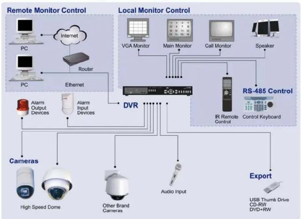
Connect the unit with other devices as shown in the system diagram to complete a video surveillance solution. The figure shows also the expandability and flexibility of this digital recording system.
System Configuration
flowchart
graph TD
    subgraph_Remote_Monitor_Control["Remote Monitor Control"]
        PC1["PC"] --> Internet["Internet"]
        Router["Router"] --> Ethernet["Ethernet"]
        PC2["PC"] --> Ethernet
        Ethernet --> AlarmOutput["Alarm Output Devices"]
        Ethernet --> AlarmInput["Alarm Input Devices"]
    end

    subgraph_Local_Monitor_Control["Local Monitor Control"]
        VGA1["VGA Monitor"] --> MainMonitor["Main Monitor"]
        MainMonitor --> IRRemote["IR Remote Control"]
        IRRemote --> AudioInput["Audio Input"]
        MainMonitor --> Speaker["Speaker"]
        IRRemote --> ControlKeyboard["Control Keyboard"]
    end

    subgraph_RS-485_Control["RS-485 Control"]
        GPS["GPS"] --> VGA1
        GPS --> MainMonitor
        GPS --> IRRemote
        GPS --> AudioInput
        GPS --> USB_Drum["USB Thumb Drive CD-RW DVD+RW"]
    end

    subgraph_Cameras["Cameras"]
        HighSpeedDome["High Speed Dome"]
        OtherBrandCameras["Other Brand Cameras"]
        AudioInputAudio["Audio Input"]
    end

    VGA1 --> MainMonitor
    MainMonitor --> IRRemote
    IRRemote --> ControlKeyboard
    GPS --> AudioInput
    GPS --> USB_Drum
2. System Setup
The notices and introduction on system installation will be described particularly in this chapter. Please follow the description to operate the unit.
In order to prevent the unit from data loss and system damage that caused by a sudden power fluctuation, use of an Uninterruptible Power Supply (UPS) is highly recommended
2.1 Position the Unit
Position / mount the DVR-4TL series in a proper place and be sure to power off the unit before making any connections. The placed location should avoid hindering or blocking the unit from airflow. Enough airflow is needed to protect the unit from overheating. The maximum allowable temperature of operating environment is 40^ C.
The unit utilizes heat-conducting techniques to transfer internal heat to the case, especially to the bottom side of the unit.

NOTE: Be sure not to remove the rubber feet, and always leave a space for air ventilation on the unit's bottom side.
2.2 Selecting Video Format
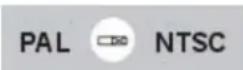
The DVR-4TL series is designed to operate under either NTSC or PAL video formats. The switch is positioned on the rear panel.
2.3 Connecting Devices to the Unit
This section lists some important notices that should be read before making any connections to the DVR-4TL series.

NOTE: Connect short-term devices, such as USB ThumbDrive ^® , USB CD-ROM, USB Hard Disk Drive, etc., only after the unit is successfully powered up.
Connecting Required Devices
Before power up the unit, you should connect cameras and a main monitor to the unit for basic operation. If needed, connect a call monitor for displaying full screen video of all installed cameras in sequence.
Connecting Short-term Device
If you plan to install any short-term devices to the DVR-4TL series and use them as part of the unit system, such as USB CD-ROM, USB Hard Disk Drive, etc, make sure those devices are connected only after the unit is powered up. Because DVR-4TL series can recognize the external devices only after the power-up process is done completely.
2.4 Rear Panel Connections
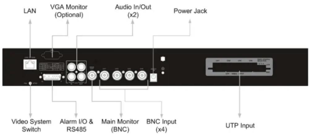
There are various connectors on the rear panel used for DVR-4TL series installations. The following figure shows the connectors by name; and followed by the detailed description of each connector.
flowchart
graph TD
    A["LAN"] --> B["Video System Switch"]
    B --> C["VGA Monitor (Optional)"]
    C --> D["Alarm I/O & RS485"]
    D --> E["Main Monitor (BNC)"]
    E --> F["BNC Input (x4)"]
    F --> G["UTP Input"]
    H["Audio In/Out (x2)"] --> C
    I["Power Jack"] --> J["Output"]
LAN Connector (RJ-45)
The DVR-4TL series is capable of networking. The LAN port opens the door of DVR-4TL series to Ethernet.
USB Connector
There is a USB 2.0 port on the rear panel for users to connect external USB devices to the unit, such as ThumbDrive ^® or CD-ROM.
Audio In / Out (x2)
The DVR-4TL series provides two sets of audio recording. Audio In RCA connector is offered for connecting an audio source device (e.g. external amplified microphone) to the unit; Audio Out RCA connector is offered for connecting an audio output device (e.g. amplified speakers) to the unit.
Call Monitor (for 8ch and 16ch Models only)
The call monitor is used to display full screen video of all installed cameras in sequence. The BNC call monitor connector allows user to connect the DVR-4TL series unit with an optional call monitor.
Main Monitor (BNC/ VGA)
BNC and VGA output connectors are offered for connecting to a main monitor. The main monitor displays live image and playback recorded video in either full-screen or split-window format. VGA output connector is optional.
Visdeo System Switch
It is used for adjusting the video system of the unit.
Video Input
A group of BNC connectors are available for video input streams from installed cameras.
Alarm I/O & RS485
The unit provides an alarm I/O and RS485 port that offers user the flexibility required to connect the unit to the other device. The pin definition for each model is listed as below tables:
natural_image
Front panel of a D-sub connector (no text or symbols visible)| Pin | Definition Pin Definition | ||
| 1 | ALARM OUT O | 9 | Alarm Out C |
| 2 | ALARM OUT COM | 10 | GND |
| 3 | RS485 D/R+ | 11 | - |
| 4 | RS485 D/R- | 12 | - |
| 5 | ALARM In 1 | 13 | - |
| 6 | ALARM In 2 | 14 | - |
| 7 | ALARM In 3 | 15 | - |
| 8 | ALARM In 4 |
Power Jack
The DVR-4TL series has a free voltage DC power connection jack. Please connect the power adapter that ships with the unit.

NOTE: Use of other power adapter may cause overloading.
UTP Input
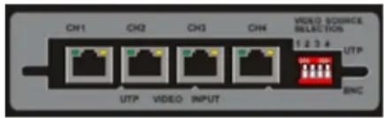
Short for Unshielded Twisted Pair, which is a popular type of cable. Due to its low cost, UTP cabling here is used for replacing BNC cabling.
There are plenty of UTP connectors positioned on the rear panel of each unit. Next to these connectors places a switch used to enable or disable this function. The switch has four DIP switches on it. These DIP switches are named by numbers; and each number corresponds to a camera. Note that BNC are alternative methods of access for video input cabling, which means if you chose BNC for Camera 1, than you have to disable its UTP function.
text_image
CH1 CH2 CH3 CH4 VIDEO SOURCE INJECTION 1 2 3 4 UTP UTP VIDEO INPUT BNC
NOTE: UTP cable transfers not only Video Signal but also power for cameras.
3. General System Setup
The DVR-4TL series allows user to access some general operations through the front panel easily. The following subsections introduce the general operations of the unit.
The regular displayed OSD information and its displayed positions are shown as following figure. The channel title will be displayed on the top-left side of the window, either in full screen mode or in multiple channel mode. The current operating mode, including Call mode, Dome-Control mode, Playback mode. Freeze mode and Sequence mode, will be displayed on the bottom-left side of the screen. And the date/time information will be displayed on the bottom-right side.
| Ch4 | ||
| Playback | 2005/11/09 | PM04:31:22 |
3.1 Front Panel Introduction
The front panel controls enable user to control the unit and preset the programmable functions.
3.1.1 LED Definition
The DVR-4TL series LEDs on the front panel are described as follows.
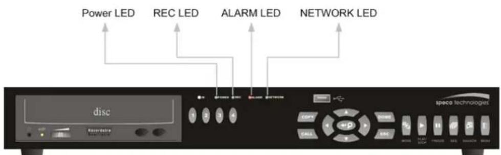
text_image
Power LED REC LED ALARM LED NETWORK LED disc space technogesPower LED (Green)
The LED lit during the period when the correct power is connected.
Network LED (Green)
The LED should be lit when DVR-4TL series is connected to a network and blink when the data is being transferred.
Alarm LED (Red)
The LED should be lit during an alarm is triggered.
REC LED (Green)
The LED should blink while the DVR-4TL series is recording.
3.1.2 Function Keys
The DVR-4TL series functional keys on the front panel for normal operation are described as follows.
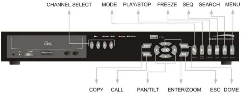
text_image
CHANNEL SELECT MODE PLAY/STOP FREEZE SEQ SEARCH MENU disc copy CALL PAN/TILT ENTER/ZOOM ESC DOMECHANNEL
- When in both Live and Playback modes, press the CHANNEL key to view the corresponding video in full screen. The number of the CHANNEL keys corresponds to the number of cameras supported by the unit.
- When in dome control mode, the key named "1" is used to access the Set/Go preset menu; the key named "2" is used to hide or display the dome setting parameters.
DOME
Press the key to enter dome control mode.
MODE
Press repeatedly to select for wanted main monitor display format. There are three available view modes: full screen and 4-window (2×2).
SEQ (Sequence)
Press to start automatic sequencing of the video coming from the installed cameras.
MENU
Press the key to call the OSD setup menu.
ESC
Press to cancel or exit from certain mode or OSD menu without changing the settings made previously.
ZOOM/ENTER
- In OSD menu or selection interface, press the key to make the selection or save settings.
- In live full screen view mode, press to view a 2× zoom image; press it again to exit zoom mode.
COPY
In Playback mode, press COPY to select the start and end point of the video you want to export. More detailed information refer to Section 4.4 Video Export.
PLAY/STOP
Press this key to switch between live image and playback video.
FREEZE
- Press FREEZE while viewing live image, the live video will be frozen. The date / time information shown on the monitor will continue updating. Press FREEZE again to return to live mode.
- Press FREEZE while playing the recorded video, the playback video will be paused. Press LEFT / RIGHT to move the recorded video reverse/forward by single step. Press FREEZE again to continue playing video.
SEARCH
In both Playback and Live mode, user can press SEARCH to call the Search menu for searching and playing recorded video by date and time or events.
Direction Keys
- In Zoom mode, these keys function as Direction keys.
- In the OSD menu, the Direction keys are used to move the cursor to previous or next fields. To change the value in the selected field, press UP/DOWN.
3.2 Power Up / Down the Unit
If you must shut down the DVR-4TL series for any reason, please use the proper shut down and power up procedures to avoid damaging your DVR unit.
To Power Up the Unit
Check the used type of power source before plug in your DVR first (the unit accepts the power input between AC100V to AC240V)
The color bar and system checking information will be shown on the monitor and disappear when the unit has been completely powered up.
To Restart / Shutdown the Unit
Press MENU and input the administrator password to access the OSD Main menu. Select
| Shutdown | |
| 1. Power Off | Execute |
| 2. Reboot | Execute |
Select this item to shut down the unit. Do not remove the power during shut down until the message "You can safely turn off DVR now!" displays.
Select this item to reboot the unit. The color bar and system checking information are displayed on the monitor until the unit is completely restarted.
3.3 Entering OSD Setup Menu
The OSD Main menu contains a list of items that are used to configure the DVR-4TL series. To enter the Main menu, press MENU and then enter Administrator or User password. The Password Verification screen displays as follows.
Password Verification
Press Channel Keys To Enter Password (4-8 Digits)
Press ◀ Key To Delete
The default passwords are shown in the following table. The same passwords are used for entering the remote viewing software specoRemote Lite.
| Administrator Password | User Password |
| 1 2 3 4 4 3 2 1□ |

NOTE: It is strongly suggested to change the passwords to prevent unauthorized access to the unit.
After entering the correct password, the Main menu is displayed.
Main Menu
- System Setup
- Monitor Setup
- Camera Setup
- Record Setup
- Sequence Setup
- Event Setup
- Database Setup
- Configuration
- Shutdown
Move the cursor up / down over the OSD items using the Direction keys and press ENTER to enter the selected sub-menu.
3.4 System Date / Time Setting
User can set the current date, time and other OSD parameters in Date/Time menu. The administrator's privileges are required for entering the submenu. In OSD Main menu, select
| Date/Time | |
| 1. Date | 2005/02/21 |
| 2. Time | PM10:39:26 |
| 3. Date/Time Display | 1 Row |
| 4. Date Display Mode | Y/M/D |
| 5. Time Display Mode | 24 HR |
| 6. Date/Time Order | Date First |
| 7. Daylight Saving Time | OFF |
| 8. DST Start | Apr, 1 st Sun, 02:00 |
| 9. DST End | Apr, Last Sun, 02:00 |
| 10. DST Bias | 60 Min |
3.4.1 Set Date / Time
Set Date / Time
Select

NOTE: The reset date / time setting applies to record new video, the date and time of previously recorded video will not be changed.

NOTE: To avoid record database corruption, after changing the date / time setting, it is recommended to clear the database.
Date / Time Display
Users are allowed to choose to set the date / time OSD displays in 1 or 2 rows. Use the UP / DOWN keys to change the setting. The default is to display the date / time OSD in one row.
Date Display Mode
This function allows user to set the OSD display type of the date / time. There are three options to select from:
Move to the item and press ENTER, the option starts blinking. Use UP / DOWN keys to change the setting. The default setting is
Time Display Mode
User can choose to set the time format to <12 hour> or <24 hour>. Use the UP / DOWN keys to change the format. The default setting is <24 hour>.
Date / Time Order
The item is used to set the order of date / time display to
3.4.2 Daylight Saving Time
Daylight Saving Time
The item is for those people who live in certain regions to observe Daylight Saving Time. Select
If the function is disabled, the DST Start / End time and DST Bias will be grayed out and cannot be accessed.

NOTE: If this function is enabled, the date/time information will be shown on the screen with a DST icon when playing back recorded video or searching video in the event list. "S" indicates summer time and "W" indicates wintertime.
DST Start / End
The items are used to program the daylight saving duration. Use Direction keys to move the cursor to the next or previous field, UP / DOWN to change the settings in the selected field.
DST Bias
The item allows user to set the amount of time to move forward from the standard time for daylight saving time. The available options are <30>, <60>, <90> and <120> minutes.
3.5 Record Schedule / Quality Setting
The Record Setup menu allows user to set recording quality, recording schedules, and other recording parameters. To setup the recording quality and schedules, you have to enter the OSD Setup Menu with correct Administrator's password. In the Main menu, move the cursor to
| Record Setup | |
| 1. Record Mode | 360×240@60PPS |
| 2. Schedule Setup | |
| 3. Preset Config | Standard |
| 4. ezRecord Setup | |
| 5. Circular Recording | ON |
| 6. Purge Data | |
3.5.1 Record Mode
The Record Mode is for selecting resolution and recording rate. The relative record settings, such as preset configuration, will follow the record mode setting. In normal circumstance, we recommend you to select 720x240@60PPS, the default, for this item.
Move the cursor to

NOTE: After changing the Record Mode setting, the warning message "This will FORMAT ALL HARDDISKS and LOAD THE FACTORY DEFAULT CONFIG!" will be shown on the screen. Press ENTER to confirm the selection, then the unit starts to format the hard disks and load the factory default settings, or press ESC to abort. We strongly recommend to backup your programmed configuration before making any changes on Record Mode settings.

NOTE: The total PPS is shared by viewing windows (by 4, 8 or 16 windows, depends on the model you have purchased), which means, even one window hasn't connected with a camera and displays no video, that window still wastes pps. But if you select
3.5.2 Schedule Setup
The Schedule Setup is used to set the day and night time, or weekend recording schedule. Select
| Schedule Setup | |
| 1. Day Time Start | AM 06:00 |
| 2. Day Time End | PM 06:00 |
| 3. Night Time Start | PM 06:00 |
| 4. Night Time End | AM 06:00 |
| 5. Weekend Schedule | YES |
| 6. Weekend Start | Fri 18:00 |
| 7. Weekend End | Mon 06:00 |
- Make appropriate changes of the start time of Day and Night Time using Direction keys.
- Press ENTER to confirm the settings or ESC to cancel.
- If you want to have a weekend record, choose
to enable the Weekend Schedule in advance and then set the Weekend Start/End time. - Press ESC to back to previous page.
3.5.3 Preset Record Configuration
The
| Halfl-D1 mode (NTSC: 720x240@30PPS) | |||
| Normal PPS | Normal Size | Event PPS | Event Size |
| 3.75 NTSC | 11 KB | 15 NTSC | 17 KB |
3.5.4 To Record Event Video Only
If you want your DVR to record images with triggered alarm (both Alarm in and Motion) only, and stop recording under normal circumstances, then follow the steps to setup your unit:
- Enter the OSD setup menu with correct password.
- Enter
menu. Then select the item . - Select
and setup this item to , which means no video will be recorded during daytime. When done, repeat the process to set the and as well.
| ezRecord Setup | |
| How Many Days To Record | 2 Days |
| Daytime Record | No |
| Night Record | No |
| Weekend Record | No |
| Overall Recording Condition | Fair |

NOTE: The recorded event video can be accessed not only through the Event List but also through the Date/ Time Research using the PLAY key on the front panel.
4. Basic Operation
The DVR-4TL series allows user to access some general operations through the front panel easily. The following sections introduce the general operations of the unit.
4.1 Viewing Live / Playback Video
The general functions in live and playback mode are described in the following sections.
4.1.1 Viewing Modes
The DVR-4TL series supplies user versatile ways of viewing both live and recorded video. Following presents these view formats.
Viewing in Full Screen
Press any CHANNEL key directly to view the corresponding camera image in full view format.
Viewing in Multi-window
Various multi-window view formats are offered for selecting. To switch between available viewing formats, press MODE repeatedly.
4.1.2 Digital Zoom
Users are able to view a 2× full screen in live mode. To view the 2× full screen, follow the steps.
- Press a CHANNEL key to view the corresponding camera in full screen.
- Press ZOOM to enter a 2× full screen zoom mode of the selected camera.
- If you need to view specific area of the 2× zoomed screen, use Direction keys to pan / tilt the zoomed area around the original image.
- Either press ZOOM again or ESC to leave the zoom mode.
4.1.3 Viewing Live Cameras
Users are allowed to view live camera in versatile view modes, including full-screen, 2×2, 3×3 and 4×4. The general operation under live mode is described as follows.
To Freeze Live Image
Press FREEZE while viewing live image, the image pauses but the date / time information does not, and the system clock continues running.
Press FREEZE to pause the live image; press FREEZE again to resume the live camera view.
4.1.4 Viewing Recorded Video
To view recorded video, user can press PLAY/STOP key directly. When press the PLAY/STOP key, the unit starts to continue playing back the recorded video from the suspended point of record. If it is the first time to use the PLAY/STOP key, the unit will playback from the very beginning of the record. Alternatively, user can select records from the Search menu to play specific video. Refer to Section 4.3 Searching Recorded Video for more information.
The Forward or Reverse speed indicator will be shown on the bottom-left of the screen, when in the playback mode.
The general operations in playback mode are described as follows.
Key Usage in Playback
The key usage is slightly changed in playback mode. Following is the key usage found in playback mode.
LEFT (Reverse Playback)
The key is used to reverse the recorded video while the unit is playing back.
Press the key repeatedly to increase the speed of reverse playback by 1× , 2× ,
4×, 8×, 16×, or 32×.
RIGHT (Forward Playback)
The key is used to play the recorded video fast forward. Press the key repeatedly to increase the speed of forward playback by 1× , 2× , 4× , 8× , 16× , or 32× .
FREEZE
Press FREEZE to pause the playback video. When the recorded video is paused, press LEFT / RIGHT to resume playback video single step reverse / forward, respectively. Press FREEZE again to continue playing video.
PLAY/STOP
Press to start playing back video, or to exit current mode or stop playing back video and back to live mode.
Pause Playback and Single Step Forward
To pause and resume recorded video, follow these steps.
- Press one of the CHANNEL keys to display the corresponding camera in full screen.
- Press FREEZE to pause the current playback image.
- Press RIGHT / LEFT Direction keys to move the video single step reverse / forward. Press and hold RIGHT/ LEFT keys to reverse / forward the video single step continuously.
- Press FREEZE again to resume the playback operation.
4.2 Sequence Setup
This section introduces you how to view in sequence mode Main Monitor and Call Monitor, if connected. Sequence function can avoid manually backtracking and give more flexibility while surveillance.
Select certain view format and press SEQ to toggle the automatic sequential sequence, press ESC to stop sequencing.
4.3 Searching Recorded Video
The DVR-4TL series is capable of searching and playing back recorded video by date and time or events. Entering the specific date and time of the wanted video, the unit will then search for the matched video and play it on the monitor. Alternatively, user can search event video by selecting channel as well.
In live or playback mode, press SEARCH to enter the Search menu, which is shown as follows.
| Search | ||
| ----Search By Time---- | ||
| From: | 2005/01/01 | 00:00:00 |
| End: | 2005/05/01 | 00:00:00 |
| Start Time: | 2005/01/01 | 00:00:00 |
| Begin Playback | ||
| ----Search By Event---- | ||
| Select Channel: CH1 | CH2 | CH3 CH4 |
| Event List | ||
4.3.1 Searching by Time
Follow the steps to search video by date and time.
- Press SEARCH key to enter the Search menu; the From Time and End Time of the available video is listed on top of the screen. The value is unchangeable.
- Use Direction keys to move the cursor for setting the Start Time; adjusting the date and time values by UP / DOWN keys.
- Press ENTER to confirm the settings or ESC to abort.
- Move the cursor to
and press ENTER to start playing back the selected video.
- Either press PLAY/STOP again to return to live video.

NOTE: If there is no available recorded video that matches your specified time and date, the unit starts playback from the next available video.

NOTE: The date/time information will be shown on the screen with a DST icon if the Daylight Saving Time function is enabled. "S" indicates summer time and "W" indicates wintertime.
4.3.2 Searching by Event
"Event List" allows you to search wanted video by event. The Event List is displayed as below figure:
| Event List | |||
| Date | Time | Ch. | Type |
| 2005/03/17 | 11:26:50 | 2 | Motion |
| 2005/03/17 | 09:53:03 | 5 | Alarm |
| 2005/03/16 | 16:14:42 | 3 | Alarm |
| 2005/03/15 | 03:45:31 | 1 | Motion |
| 2005/03/12 | 22:27:56 | 1 | Alarm |
| 2005/03/12 | 10:09:29 | 7 | Motion |
| 2005/03/11 | 12:18:20 | 6 | Motion |
| 2005/03/10 | 05:16:00 | 4 | Alarm |
| 2005/03/08 | 17:11:37 | 2 | Motion |
| 2005/03/08 | 16:29:10 | 8 | Motion |
| 2005/03/08 | 03:22:17 | 2 | Alarm |
The list displays each event by date, time, triggered camera and alarm type. As some events are deleted, others are displayed. The latest recorded event video will be listed on the top.
Follow these steps to search event video through Event List:
- Press SEARCH to enter the Search menu.
- To search event video that has been recorded on a specific camera, use LEFT / RIGHT to move the cursor and press ENTER to select or de-select a channel.
- Move the cursor to
and press ENTER to list the event video of the selected channels. The Event List displays. - To exit the event list, press ESC.
Follow the steps to playback video from Event List.
- Press and hold UP / DOWN to scroll through the Event List.
- Press ENTER to play back the selected event record.
- Press PLAY/STOP to return to live mode.
4.4 Video Export
The unit allows you to export wanted video to an external device, such as a USB ThumbDrive ^® , and save the video to *.drv file.
If you want to export video to an external device, make sure the external storage has been connected to the DVR unit and the port has been set appropriately for video export.
According to the size of video, the export may take you about 10 minutes to 1 hour.
4.4.1 ezBurn Introduction
Built with the ezBurn technology, ezBurn function provides users the easier way to export desired video with CD-RW built in or to an external device connected, such as an USB ThumbDrive ^® .
TWO keys (SEARCH and COPY) and THREE touches are all you need for completing the export. The whole exporting process will be done through the front panel, but no need to enter the OSD setup menu.
The ezburn export process is illustrated as below figure:

text_image
Press SEARCH key Start playing back video Press COPY key ezBurn start time Press COPY key ezBurn end timeThe whole process is described step by step in the following sections.
4.4.2 To Export Normal Video
To Export normal video to external device, follow these step:
- Press SEARCH and play wanted normal video by entering date and time. Note if you are viewing in multiple channel mode, please make sure there is no window displaying in Live mode. Otherwise, the export won't work.
- After entering playback mode, plays the video and press COPY on the point that you want to start the export. The playback continues.
- Press COPY again on the point that you want to end the export. Now, the "ezBurn" window displays as below figure. The information shown on the window is for read only.
ezBurn confirmation
Selected Device: Built-in-CD-RW
All data on the disc will be erased.
Exported Required Size = 11 MB
Real Export Range:
From: 2005/11/07 AM10:41:13
To: 2005/11/07 AM10:41:21
Enter: YES ESC: NO
- If there is no any exportable external device connected to the DVR unit, then a warning message will be shown on the screen, as below figure:
No exportable device detected.
Please install the target device/media
to the DVR.
Enter: Retry ESC: Exit
- Press ENTER to start the export; or, press ESC to abort.
4.4.3 To Export Event Video
To export event video, follow these steps:
- Press SEARCH and play wanted event video. To play event video, refer to Section 4.3 Searching Recorded Video.
- After entering the playback mode, press COPY. The "ezBurn" window displays as below figure. The information shown on it is for read only.
| ezBurn confirmation | ||||
| Selected Device: Built-in-CD-RW | ||||
| All data on the disc will be erased. | ||||
| Exported Required Size = 11 MB | ||||
| Export Event Info: | ||||
| Data | Time | Ch Type | ||
| 205/11/07 | AM10:42:35 | 8 | Motion | |
| Enter: YES | ESC: NO | |||
- If there is no any exportable external device connected to the DVR unit, a warning message will be shown on the screen
- Press ENTER to start the export the whole event video to the connected device; or, press ESC to abort.
4.5 Deleting Recorded Video
User can delete the Normal and Event recorded video in Purge Data menu. The administrator password is required to access the function. Select
| Purge Data | |
| 1. Purge All Data | NO |
| 2. Purge All Event Data | NO |
| 3. Purge Event Before | 2000/01/01 |
| 4. Start to Purge | NO |
The first four items are used to select the data that should be purged. The items are described as follows. After select the data you want to purge, set the fifth item
Purge All Data
Select the item to delete all recorded video from database.
Purge All Event Data
Select the item to delete all event video from database.
Purge Event Before
The item is used to delete event video that recorded before a specific date. The default of this item is <2000/01/01>.
4.6 Dome Control
DVR-4TL series allows user to control a dome camera by the front panel.
In Live mode, user can press CHANNEL key to display the desired dome camera in full view. To enter Dome Control mode, press the DOME key and press channel key 2 to display the hint screen; to exit the Dome Control mode and back to live mode, press ESC or DOME.
To configure the dome controls settings, see the following sections.
4.6.1 Dome Connection
Follow the steps to install dome camera.
- See section 2.4 Rear Panel Connections for RS-485 port pin definition.
- Refer to the following figure. Connect the R+, R- terminals on the dome camera to the D+, D- terminals on the RS-485 port by RS-485 cable respectively.
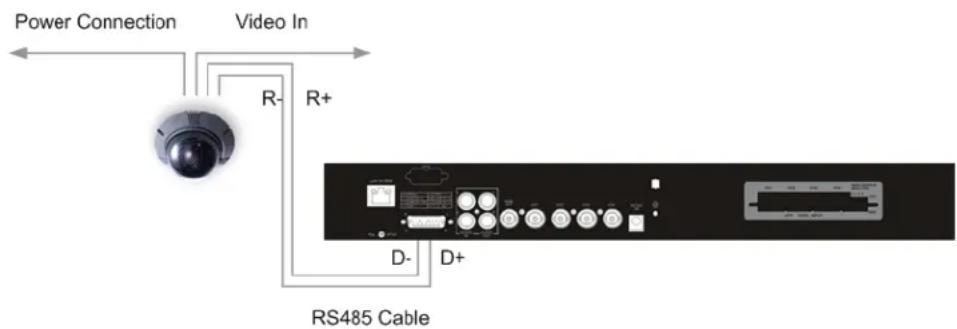
text_image
Power Connection Video In R- R+ D- D+ RS485 Cable4.6.2 Dome Protocol Setup
The Dome Protocol item lists the available dome protocols for communicating with dome cameras connected to the DVR-4TL series. From the Main menu, select
| Camera Setup | |
| 1. Camera Select | CH1 |
| 2. Dome Protocol | None |
| 3. Dome ID | 0 |
| 4. Camera Title | |
| 5. Covert | NO |
| 6. Termination | NO |
| 7. Brightness | 0 |
| 8. Contrast | 0 |
| 9. Saturation | 0 |
| 10. Hue | 0 |
To configure dome protocol, select a camera first and set the communications protocol associated with dome camera using the Direction keys and ENTER. The available protocol includes

NOTE: The settings become effective after saving the changes and exiting from the menu.
4.6.3 RS485 Setup
DVR-4TL series controls the domes via RS-485 communication protocol. The RS-485 parameters in DVR-4TL series must be set to the same parameters as the protocol for RS-422 setup of the dome.
Users are allowed to change the RS-485 settings of the DVR-4TL series. Select
| RS485 Setup | |
| 1 Unit ID | 224 |
| 2 Baud Rate | 9600 |
| 3 Bits | 8 |
| 4 Stop | 1 |
| 5 Parity | None |
The ID number must match the ID address set by the dome. The Unit ID is in the range of 1 to 255. The default ID is 224. Note that no two devices on the same bus should be given the same ID address, or a conflict may occur.
The default DVR-4TL series RS-485 settings are 9600 Baud, 8 Data Bits, 1 Stop Bit and No Parity.

NOTE: The settings become effective after saving the changes and exiting from the menu.
4.6.4 Dome Controlling Keys
The function keys used in Dome Control are described as follows.

text_image
Set/Go Preset Toggle hint Screen Iris Open Iris Close Focus Far Focus Near Zoom Out Zoom In disc 1 2 3 4 EASY FALL CIME ESC Enter/ Auto Pan/ Tilt Enter Dome Mode ESCSet / Go Preset
This key is used to enter the Dome Preset menu to set up certain position as a preset and go to the predetermined preset positions for viewing.
Toggle Hint Screen
This function is used to avoid viewing the dome parameter information while controlling dome camera. Press this key to hide the screen. Press it again to redisplay the screen.
Iris Open
Use to open the Iris on the dome camera.
Focus Near
Use to focus the dome camera near.
Zoom In
Use to zoom the dome camera in. This function is for user to choose the viewing area, more or less of it.
ESC
Use to leave dome control mode and return to live and full screen viewing mode.
Auto / Enter
- In OSD Menu mode, the key is used to make selection.
- In dome control mode, this key is used to activate automatic focus and iris function.
Iris Close
Use to close the Iris on the dome camera.
Focus Far
Use to focus the selected dome camera far.
Zoom Out
Use to zoom the dome camera out. This function is for user to choose the viewing area, more or less of it.
Pan / Tilt
Use to pan and tilt dome camera.
4.6.5 Setting Preset Points
The DVR-4TL series allows user to set preset positions; the amount of preset points depends on the dome manufacturer.
Follow the steps to set preset points.
- Press a Channel key to view the corresponding camera in full screen.
- Then press DOME to enter dome control mode.
- Use Direction keys to position the dome camera to desired position.
- Press 2 to view the dome control Hint Screen; press 2 again to toggle the Hint Screen.
| Hint Screen |
| DOME / ESC: Exit |
| MODE / PLAY: Iris Open / Close |
| SEQ / FREEZE: Focus Near / Far |
| MENU / SEARCH: Zoom In / Out |
| ENTER: Auto Focus / Iris |
| ◀▲▼▶: Pan / Tilt |
| CH1: Set / Go Preset |
| CH2: Hint Screen On / Off |
| Dome Control |
- Press 1 to access the Set/Go Preset function. The Dome Preset menu is displayed.
| Dome Preset | ||
| Index | Set Preset | Go Preset |
| 1 | NO | NO |
| 2 | NO | NO |
| 3 | NO | NO |
| 4 | NO | NO |
| 5 | NO | NO |
| 6 | NO | NO |
| 7 | NO | NO |
- Use UP / DOWN keys to select the desired preset number from the menu.
- Set the
of the selected preset number to , and press ENTER to save the position. Now the preset is set and ready to call.
4.6.6 Calling Preset Points
Follow the steps to call preset points.
- Press a Channel key to view the corresponding camera in full screen.
- Then press DOME to enter dome control mode.
- Press 2 to view the dome control Hint Screen; press 2 again to toggle the Hint Screen.
- Press 1 to access the Set/Go Preset function.
| Dome Preset | ||
| Index | Set Preset | Go Preset |
| 1 | NO | NO |
| 2 | NO | NO |
| 3 | NO | NO |
| 4 | NO | NO |
| 5 | NO | NO |
| 6 | NO | NO |
| 7 | NO | NO |
- Use UP / DOWN keys to select the desired preset number from the menu.
- Set the
of the selected preset number to , and press ENTER to call the preset point. - Now the selected dome camera rotates to the preset position automatically.
Appendix A: Technical Specifications
All specifications are subject to change without notice.
| Specifications 4ch Model | ||
| Video | ||
| Input | BNCx4, 1.0Vp-p, 75 ohm | |
| Video Standard | NTSC/PAL switch selectable | |
| Video Operation | Triplex (Live, Record, Playback, Remote, and Internet access) | |
| Outputs | Main Monitor | BNCx1, 1.0Vp-p, 75 ohm |
| VGA | 800x600, 1024x768, 1280x1024 pixels @ 60Hz | |
| Picture Refresh Rate | NTSC: 60PPS | |
| Digital Zoom | 2x2 | |
| Camera Installation | Plug & Play | |
| Audio | ||
| Input | RCAx1, Line-In | |
| Output | RCAx1, Line-Out | |
| Recording | ||
| Compression Method | MPEG-4 Advanced Simple Profile | |
| Recording Mode | Schedule, Alarm, Motion Detection | |
| Pre-alarm | Yes | |
| Resolution & Rate | NTSC: 30PPS@720x480 pixelsNTSC: 60PPS@720x240 pixels | |
| Recording Quality | Best Quality, Standard, ezRecord, Extended Record, DSL | |
| Image Size | 8K to 20K Byte/Picture | |
| Storage Mode | Linear/Circular | |
| Playback | ||
| Playback | Play, Stop, Pause, Rewind, Forward, Search | |
| Playback Speed Adjustment | Yes (1x, 2x, ...32x) | |
| Retrieve | Date/Time, Event | |
| Storage | ||
| Built-in HDD | 1 Front Panel Removable HDD | |
| Alarm | |
| Alarm Input | X4, D-Sub 15 pin |
| Alarm Relay Output | X1, D-Sub 15 pin |
| Alarm Detection | N.C./N.O., Programmable |
| Motion Detection | 16x12 |
| Video Loss Detection | Programmable |
| Auditory Alert | Built-in Buzzer |
| Communication | |
| Communication Protocol | RS-485 DSCP |
| Remote Control Software | specoRemote Lite |
| Network Connectivity | Ethernet RJ-45 connector, 10/100Mbps, supports DHCP |
| LAN Remote Control | IE Browser, Windows AP |
| Dome Control | IE Browser, Windows AP, Front Panel |
| Dome Control Protocol | DynaColor, Pelco P, Pelco D, AD422, Fastrax 2 |
| Remote Operation | Monitoring, Playback, Instant Recording, Dome Camera Control |
| On-Screen Display | |
| Search | Based on Time or Event |
| Play/Pause/REW/FF | Control Playback Direction & Speed |
| Password Control | 2 Level, Administrator/User |
| General | |
| Unit Dimension (WxHxD) | 440x50x340mm (17.3x3.45x13.58 inches) |
| Operation Temperature | 0°C - 40°C (32°F - 104°F) |
| Relative Humidity | 30% - 90% Non-condensing |
| Power Consumption & Input | External Adapter, AC 100 ~ 240V to DC12V |