NPort 6610-32-48V - Server Moxa - Free user manual and instructions
Find the device manual for free NPort 6610-32-48V Moxa in PDF.


| Product Type | Serial Device Server |
| Model | NPort 6610-32-48V |
| Brand | Moxa |
| Number of Serial Ports | 32 (RS-232/422/485) |
| Ethernet Ports | 2 x 10/100BaseT(X) with redundant ring support |
| Input Voltage | 48 VDC (dual redundant power inputs) |
| Power Consumption | 12 W (max) |
| Dimensions (W x H x D) | 440 x 44 x 354 mm (19-inch, 1U) |
| Weight | 3.5 kg |
| Operating Temperature | -10 to 60 °C |
| Storage Temperature | -40 to 85 °C |
| Relative Humidity | 5 to 95% (non-condensing) |
| Serial Port Protection | 15 kV ESD protection for each serial port |
| Management Functions | Web, Telnet, serial console, SNMP, Windows utility |
| Security Features | SSL/SSH encryption, IP filtering, MAC address binding |
| Mounting | 19-inch rackmount or wall mount with optional kit |
| Certifications | CE, FCC, UL, EN 50121-4 (railway) |
| MTBF | 250,000 hours |
| Warranty | 5 years |
| Maintenance | Clean with dry soft cloth; avoid liquids and abrasive cleaners |
| Safety Instructions | Use only supplied power adapter; disconnect power before cleaning; do not block ventilation |
| Spare Parts & Repairability | Contact Moxa support for spare parts or repairs; no user-serviceable parts inside |
Frequently Asked Questions - NPort 6610-32-48V Moxa
User questions about NPort 6610-32-48V Moxa
0 question about this device. Answer the ones you know or ask your own.
Ask a new question about this device
Download the instructions for your Server in PDF format for free! Find your manual NPort 6610-32-48V - Moxa and take your electronic device back in hand. On this page are published all the documents necessary for the use of your device. NPort 6610-32-48V by Moxa.
USER MANUAL NPort 6610-32-48V Moxa
NPort 6600 Series Quick Installation Guide
Version 12.1, January 2021
Technical Support Contact Information www.moxa.com/support
MOXA®
© 2021 Moxa Inc. All rights reserved.
P/N: 1802066500020

Overview
The NPort 6600 series of serial device servers includes 8-port, 16-port, and 32-port models for connecting larger numbers of serial devices to Ethernet. Some applications now also require better security when transmitting data through a network. The NPort 6600 series of device servers use DES, 3DES, and AES data encryption to provide secure network communication.
Package Checklist
Before Installing your NPort 6600 series secure device server, verify that the package contains the following items:
- NPort 6600 device server
• Power Cord (AC models only) - Two rack-mount ears
- Documentation
- Quick installation guide (printed)
- Warranty card
• CBL-RJ45M9-150: 8-pin RJ45 to DB9 male connection cable, 150 cm
Optional Accessories
• DK-35A: 35 mm DIN-Rail Mounting Kit
• DIN-Rail Power Supply
- NM-TX01/NM-TX01-T: Network module with one 10/100BaseTX Ethernet port (RJ45 connector; supports cascade redundancy)
- NM-FX01-S-SC/NM-FX01-S-SC-T: Network module with one 100BaseFX single mode fiber port (SC connector; supports cascade redundancy)
- NM-FX02-S-SC/NM-FX02-S-SC-T: Network module with two 100BaseFX single mode fiber ports (SC connectors; supports cascade redundancy)
- NM-FX01-M-SC/NM-FX01-M-SC-T: Network module with one 100BaseFX multiode fiber port (SC connector; supports cascade redundancy)
- NM-FX02-M-SC/NM-FX02-M-SC-T: Network module with two 100BaseFX multi-mode fiber ports (SC connectors; supports cascade redundancy)
NOTE: Please notify your sales representative if any of the above items is missing or damaged.
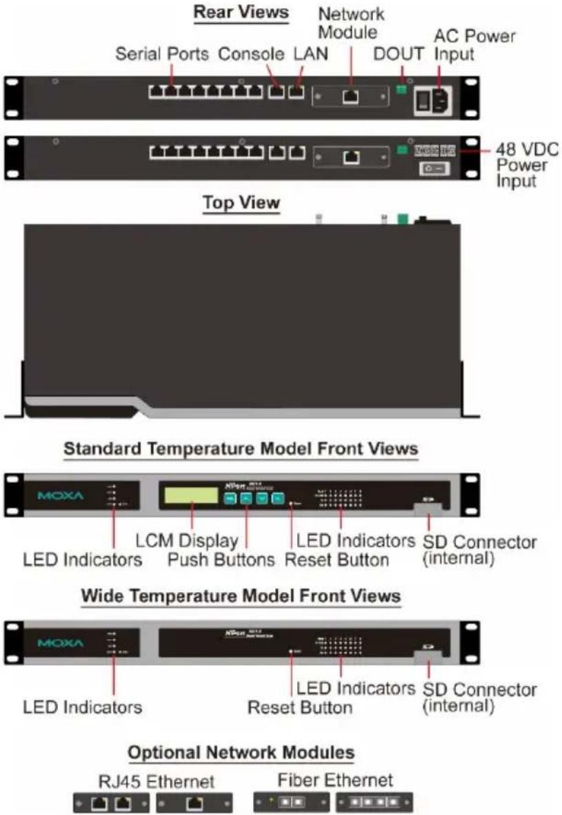
Hardware Introduction
Demonstrated 8 port model to be an example.
text_image
Rear Views Serial Ports Console LAN Network Module AC Power Input 48 VDC Power Input Top View Standard Temperature Model Front Views MOXA LCM Display LED Indicators SD Connector (internal) LED Indicators Push Buttons Reset Button LED Indicators Reset Button Wide Temperature Model Front Views MOXA LED Indicators SD Connector (internal) LED Indicators Reset Button Optional Network Modules RJ45 Ethernet Fiber EthernetReset Button
Press the Reset button continuously for 5 second to load factory defaults: Use a pointed object to press the reset button. Release the button after the Ready LED stops blinking.
RS-485 adjustable pull up/down resistor (150/1 KΩ)
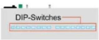
The NPort 6650 has 3 DIP Switches associated with each serial port for configuring the pull up/down resistors for RS-485 applications. The switches are located in a recess on the bottom of the NPort 6650. To access the switches, first remove the panel covering the recess.
text_image
DIP-Switches| SW | 1 | 2 | 3 |
| Pull Up | Pull Down | Terminator | |
| ON | 1 KΩ | 1 KΩ | 120 Ω |
| OFF | 150 KΩ | 150 KΩ | - |
NOTE For RS-232 applications, all DIP Switches for the port should be set to the OFF position.
Rack Mounting
Use four screws to attach the NPort 6610/6650 to a standard rack.

text_image
MOXA =0 =0 =0 0cm NPort MOSA 12 13 14 15 16 17 18 19 20 21 22 23 24 25 26 27 28 29 30 31 32 33 34 35 36 37 38 39 40 41 42 43 44 45 46 47 48 49 50 51 52 53 54 55 56 57 58 59 60 61 62 63 64 65 66 67 68 69 70 71 72 73 74 75 76 77 78 79 80 12:12:13:14:15:16:17:18:19:20:21:22:23:24:25:26:27:28:29:30:31:32:33:34:35:36:37:38:39:40:41:42:43:44:45:46:47:48:49:50:51:52:53:54:55:56:57:58:59:60:61:62:63:64:65:66:67:68:69:70:71:72:73:74:75:76:77:78:79:80LED Indicators
| Name | Color | Function | |
| PWR | Red | Power is being supplied to the power input. | |
| Ready | Red | Steady on: | Power is on and the NPort 6600 series is booting up. |
| Blinking: | IP conflict, DHCP or BOOTP server not responding, or relay output. Check relay output first. If still blinking, then there is an IP conflict, or the DHCP or BOOTP server did not respond properly. | ||
| Green | Steady on: | Power is on and the NPort 6600 series is functioning normally. | |
| Blinking: | The device server has been located by the Administrator's Locator function. | ||
| Off | Power is off, or power error condition exists. | ||
| Link | Orange | 10 Mbps Ethernet connection. | |
| Green | 100 Mbps Ethernet connection. | ||
| Off | Ethernet cable is disconnected, or has a short. | ||
| P1-P16 Tx | Green | Serial port is transmitting data. | |
| Off No data is being transmitted through the serial port | |||
| P1-P16 Rx | Orange | Serial port is receiving data.. | |
| Off | No data is being received through the serial port. | ||
| FX | Orange | Steady on: | Ethernet fiber connection, but port is idle. |
| Blinking: | Fiber port is transmitting or receiving data. | ||
| P1-P16 in-use LEDs | Green | Serial port is opened by server side software. | |
| Off | Serial port is not opened by server side software. | ||
| Alarm | Red | The relay Dout is open (exception) | |
| Off | The relay Dout is Shorted (normal) | ||
| Module | Green | Network module is plugged in and detected | |
| Off | No module present | ||
LCM Display Panel
The NPort 6600 display panel will show the model name, server name, and IP address when powered up
| N | P | 6 | 6 | 1 | 0 | _ | 6 | 6 | 1 | 0 | 2 | |||
| 1 | 9 | 2 | . | 1 | 6 | 8 | . | 1 | 2 | 7 | . | 2 | 5 | 4 |
Operating the LCM Panel
There are four push buttons on the NPort 6600's top panel for operating the server's LCM panel. The function of each button is described below:
| Button | Action |
| MENU | Activates the main menu, or returns to a lower level. |
| ^ | Scrolls up through a list of items shown on the LCM panel's second line. |
| ∨ | Scrolls down through a list of items shown on the LCM panel's second line. |
| SEL | Selects the option listed on the LCM panel's second line. |
Detailed LCM panel operating instructions can be found on the Document and Software CD in the "NPort 6600 Series User's Manual."
NOTE LCM display panel and push buttons only for standard temperature model.
Hardware Installation Procedure
STEP 1: Connect the NPort 6600 device server to a suitable power source. AC models: Connect the 100 to 240 VAC power cord to the NPort 6600's power input.
DC models: Connect the terminal block to a battery.
STEP 2: Connect the NPort 6600 series to a network. Use a standard straight-through Ethernet cable to connect to a hub or switch. Use a cross-over Ethernet cable when connecting to your computer's Ethernet port (e.g., when setting up or testing the NPort 6600 server).
STEP 3: Connect the NPort 6600's serial ports to your serial devices.
Software Installation Information
For the NPort's configuration, the default IP address of the NPort is 192.168.127.254. You may log in with the account name admin and password moxa to change any settings to meet your network topology (e.g., IP address) or serial device (e.g., serial parameters).
For software installation, download the relative utilities from Moxa's website:
https://www.moxa.com/support/support_home.aspx?isSearchShow=1
- Download the NPort Windows Driver Manager and install it as the driver to run with Real COM mode of the NPort Series.
- Execute NPort Windows Driver Manager; then map the virtual COM ports on your Windows platform.
- You may refer to Pin Assignment Async RS-232 port section to loop back pin 4 and pin 5 for the RS-232 interface to carry out a self test on the device.
- Use HyperTerminal or a similar program (you may download Moxa's program, called PComm Lite) to test whether the device is good or not.
Pin Assignments and Cable Wiring
Pin Assignments (NPort 6610/6650)
| Pin | RS-232 | RS-422, 4-wire RS -485 | 2-wire RS-485 |
| 1 | DSR | - | - |
| 2 | RTS | TxD+ | - |
| 3 | GND | GND | GND |
| 4 | TxD | TxD- | - |
| 5 | RxD | RxD+ | Data+ |
| 6 | DCD | RxD- | Data- |
| 7 | CTS | - | - |
| 8 | DTR | - | - |
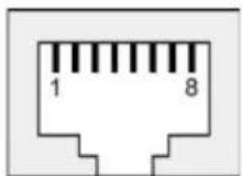
Pin Mapping for RS-232 Cables (NPort 6610/6650)
| NPort6610/6650 | Serial Device | ||||||
| RJ45 | DB9(M) | DB9(F) | DB25(M) | DB25(F) | |||
| DSR | 1 | ← | 6 | 4 | 6 | 20 | DTR |
| RTS | 2 | → | 7 | 8 | 4 | 5 | CTS |
| GND | 3 | — | 5 | 5 | 7 | 7 | GND |
| TxD | 4 | → | 3 | 2 | 2 | 3 | RxD |
| RxD | 5 | ← | 2 | 3 | 3 | 2 | TxD |
| DCD | 6 | ← | 1 | 1 | 8 | 8 | DCD |
| CTS | 7 | ← | 8 | 7 | 5 | 4 | RTS |
| DTR | 8 | → | 4 | 6 | 20 | 6 | DSR |
Pin Mapping for RS-422/4W-RS-485 Cables (NPort 6650)
| NPort 6650 | Serial Device | ||||||
| RJ45 | DB9(M) | DB9(F) | DB25(M) | DB25(F) | |||
| TxD+ | 2 | → | 7 | 8 | 4 | 5 | RxD+ |
| GND | 3 | — | 5 | 5 | 7 | 7 | GND |
| TxD- | 4 | → | 3 | 2 | 2 | 3 | RxD- |
| RxD+ | 5 | ← | 2 | 3 | 3 | 2 | TxD+ |
| RxD- | 6 | ← | 1 | 1 | 8 | 8 | TxD- |
Pin Mapping for 2W-RS-485 Cables (NPort 6650)
| NPort 6650 | Serial Device | ||||||
| RJ45 | DB9(M) | DB9(F) | DB25(M) | DB25(F) | |||
| GND | 3 | — | 5 | 5 | 7 | 7 | GND |
| Data+ | 5 | 2 | 3 | 3 | 2 | Data+ | |
| Data- | 6 | 1 | 1 | 8 | 8 | Data- | |
Japan Regulatory Compliance (VCCI)
The NPort 6000 Series complies with the requirements of VCCI Class A Information Technology Equipment (ITE).

WARNING
If this equipment is used in a domestic environment, radio disturbance may arise. When such problems occur, the user may be required to take corrective action.