Sarix Professional IMP531-1ERS - Security Camera Pelco - Free user manual and instructions
Find the device manual for free Sarix Professional IMP531-1ERS Pelco in PDF.


User questions about Sarix Professional IMP531-1ERS Pelco
0 question about this device. Answer the ones you know or ask your own.
Ask a new question about this device
Download the instructions for your Security Camera in PDF format for free! Find your manual Sarix Professional IMP531-1ERS - Pelco and take your electronic device back in hand. On this page are published all the documents necessary for the use of your device. Sarix Professional IMP531-1ERS by Pelco.
USER MANUAL Sarix Professional IMP531-1ERS Pelco
Sarix® Professional 3
IMP Series
Indoor | Environmental Vandal Dome
Installation Manual
natural_image
Technical line drawing of a mechanical sensor or security camera with no visible text or symbolsIMP231-1ES IMP231-1IS
IMP331-1ES IMP331-1IS
IMP531-1ES IMP531-1IS
IMP131-1ERS IMP131-1IRS
IMP231-1ERS IMP231-1IRS
IMP331-1ERS IMP331-1IRS
IMP531-1ERS IMP531-1IRS
C6627M-A-EN(07/19)
Contents
Important Notices .... 3
Regulatory Notices [FCC Class A]....3
Radio and Television Interference ....3
Legal Notice [Audio Notice]....3
Video Quality Caution ....3
Frame Rate Notice Regarding User Selected Options....3
Open Source Software....4
Korean Class A EMC 4
ESD Warning 4
Warranty 4
Network Topology Statement....4
Preface....5
- Product Overview....6
1.1 Dimensions....6
1.2 Model Instruction 7
1.3 Physical Characteristics....8
- Installation and Connection....10
2.1 Unpacking Everything....10
2.2 Optional Accessories....10
2.3 Installation 11
2.3.1 Checking Appearance 11
2.3.2 Disassembling the Camera....11
2.3.3 Mounting the Camera....12
2.3.4 Connecting the Cables 17
2.3.5 Positioning the Camera 18
2.3.6 Adjusting Focus....19
2.3.7 Completing the Camera Assembly 19
2.3.8 Lower Dome Defog....20
Pelco Troubleshooting Contact Information 21
Important Notices
REGULATORY NOTICES [FCC CLASS A]
This device complies with Part 15 of the FCC Rules. Operation is subject to the following two conditions: (1) this device may not cause harmful interference, and (2) this device must accept any interference received, including interference that may cause undesired operation.
RADIO AND TELEVISION INTERFERENCE
This equipment has been tested and found to comply with the limits of a Class A digital device, pursuant to Part 15 of the FCC rules. These limits are designed to provide reasonable protection against harmful interference when the equipment is operated in a commercial environment. This equipment generates, uses, and can radiate radio frequency energy and, if not installed and used in accordance with the instruction manual, may cause harmful interference to radio communications. Operation of this equipment in a residential area is likely to cause harmful interference in which case the user will be required to correct the interference at his own expense.
Changes and Modifications not expressly approved by the manufacturer or registrant of this equipment can void your authority to operate this equipment under Federal Communications Commission's rules.
NOTE: Improper use of audio/visual recording equipment may subject you to civil and criminal penalties. Applicable laws regarding the use of such capabilities vary between jurisdictions and may require, among other things, express written consent from the recorded subjects. You are solely responsible for insuring strict compliance with such laws and for strict adherence to any/all right of privacy and personality.
VIDEO QUALITY CAUTION
FRAME RATE NOTICE REGARDING USER SELECTED OPTIONS
Pelco systems are capable of providing high quality video for both live viewing and playback. However, the systems can be used in lower quality modes, which can degrade picture quality, to allow for a slower rate of data transfer and to reduce the amount of video data stored. The picture quality can be degraded by either lowering the resolution, reducing the picture rate, or both. A picture degraded by having a reduced resolution may result in an image that is less clear or even indiscernible. A picture degraded by reducing the picture rate has fewer frames per second, which can result in images that appear to jump or move more quickly than normal during playback. Lower frame rates may result in a key event not being recorded by the system.
Judgment as to the suitability of the products for users' purposes is solely the users' responsibility. Users shall determine the suitability of the products for their own intended application, picture rate and picture quality. In the event users intend to use the video for evidentiary purposes in a judicial proceeding or otherwise, users should consult with their attorney regarding any particular requirements for such use.
OPEN SOURCE SOFTWARE
This product includes certain open source or other software originated from third parties that is subject to the GNU General Public License (GPL), GNU Library/Lesser General Public License (LGPL) and different and/or additional copyright licenses, disclaimers, and notices.
The exact terms of GPL, LGPL, and some other licenses are provided to you with this product. Please refer to the exact terms of the GPL and LGPL at http://www.fsf.org (Free Software Foundation) or http://www.opensource.org (Open Source Initiative) regarding your rights under said license. You may obtain a complete corresponding machine-readable copy of the source code of such software under the GPL or LGPL by sending your request to digitalsupport@pelco.com; the subject line should read Source Code Request. You will then receive an email with a link for you to download the source code.
This offer is valid for a period of three (3) years from the date of the distribution of this product by Pelco.
KOREAN CLASS A EMC
WARNING: This product is sensitive to Electrostatic Discharge (ESD). To avoid ESD damage to this product, use ESD safe practices during installation. Before touching, adjusting or handling this product, correctly attach an ESD wrist strap to your wrist and appropriately discharge your body and tools. For more information about ESD control and safe handling practices of electronics, please refer to ANSI/ESD S20.20-1999 or contact the Electrostatic Discharge Association (www.esda.org).
WARRANTY
For information about Pelco's product warranty and thereto related information, refer to www.pelco.com/warranty.
NETWORK TOPOLOGY STATEMENT
IMPORTANT NOTE. PLEASE READ. The network implementation is shown as a general representation only and is not intended to show a detailed network topology. Your actual network will differ, requiring changes or perhaps additional network equipment to accommodate the system as illustrated. Please contact your local Pelco representative to discuss your specific requirements.
Preface
This installation manual is to be used as a reference for the installation of the camera unit including wire connection, camera installation, and camera adjustment.
This manual provides the following information.
• Product Overview: The main functions and system requirements of the unit.
• Installation and Connection: Instructions on unit installation and wire connections.
1. Product Overview
1.1 Dimensions
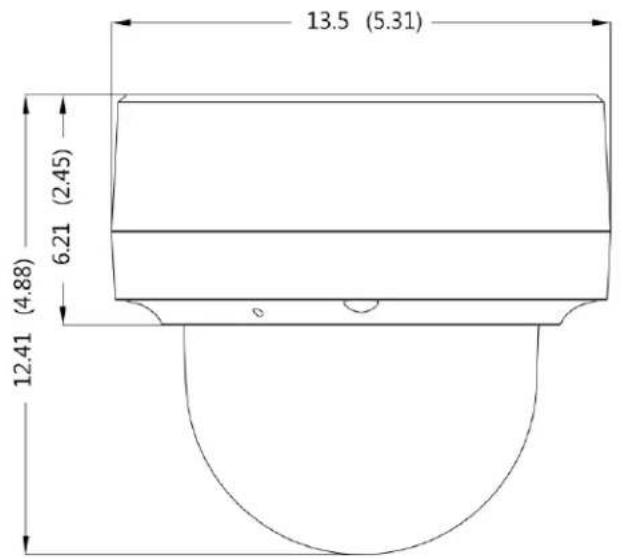
The dimensions of the Sarix Professional 3 Series Vandal Dome are depicted within the Figure 1-1 below.

NOTE: VALUES IN PARENTHESES ARE INCHES; ALL OTHERS ARE CENTIMETERS.
text_image
13.5 (5.31) 6.21 (2.45) 12.41 (4.88)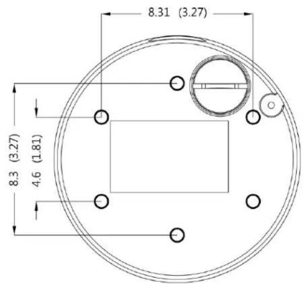
text_image
8.31 (3.27) 8.3 (3.27) 4.6 (1.81)INDOOR | ENVIRONMENTAL VANDAL DOME
FIGURE 1-1: PHYSICAL DIMENSIONS
IMP SERIES INDOOR DOME
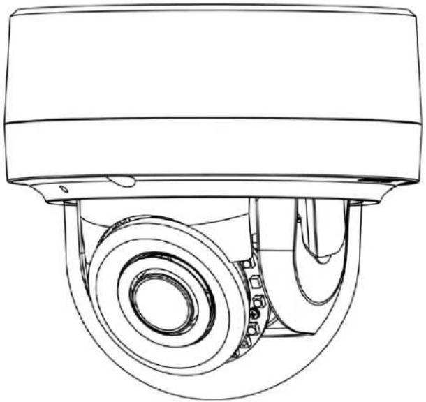
The physical appearance and installation methods for the models indicated within the list below are, by and large, the same. Therefore, in this manual the IMP531-1IRS model is an example to use as a reference to apply to all the varied models.
| Model | Description |
| IMP131-1IRS | 1MP Indoor Vandal Dome with IR and Vari-focal lens |
| IMP231-1IS | 2MP Indoor Vandal Dome with Vari-focal lens |
| IMP231-1IRS | 2MP Indoor Vandal Dome with IR and Vari-focal lens |
| IMP331-1IS | 3MP Indoor Vandal Dome with Vari-focal lens |
| IMP331-1IRS | 3MP Indoor Vandal Dome with IR and Vari-focal lens |
| IMP531-1IS | 5MP Indoor Vandal Dome with Vari-focal lens |
| IMP531-1IRS | 5MP Indoor Vandal Dome with IR and Vari-focal lens |
TABLE 1-1: MODEL LIST FOR INDOOR DOME
IMP SERIES ENVIRONMENTAL DOME
The physical appearance and installation methods for the models indicated within the list below are, by and large, the same. Therefore, in this manual the IMP531-1ERS is an example to use as a reference to apply to all the varied models.
| Model | Description |
| IMP131-1ERS | 1MP Environmental Vandal Dome with IR and Vari-focal lens |
| IMP231-1ES | 2MP Environmental Vandal Dome with Vari-focal lens |
| IMP231-1ERS | 2MP Environmental Vandal Dome with IR and Vari-focal lens |
| IMP331-1ES | 3MP Environmental Vandal Dome with Vari-focal lens |
| IMP331-1ERS | 3MP Environmental Vandal Dome with IR and Vari-focal lens |
| IMP531-1ES | 5MP Environmental Vandal Dome with Vari-focal lens |
| IMP531-1ERS | 5MP Environmental Vandal Dome with IR and Vari-focal lens |
TABLE 1-2: MODEL LIST FOR ENVIRONMENTAL DOME
1.3 Physical Characteristics
text_image
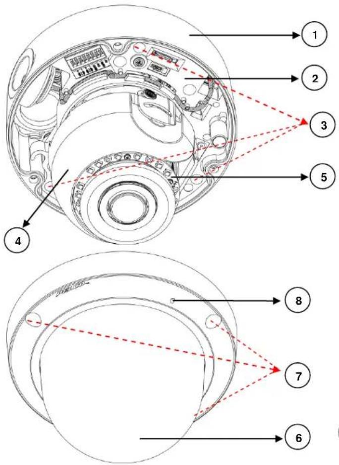
Technical diagram of a device's internal structure with numbered annotations pointing to different components.FIGURE 1-2: CAMERA CONNECTIONS AND FEATURES 1/3
text_image
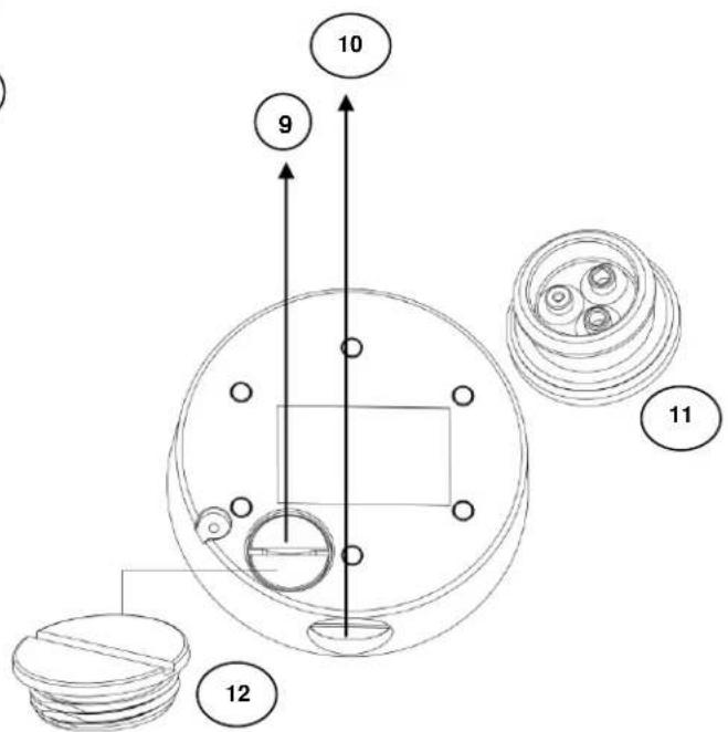
10 9 11 12FIGURE 1-3: CAMERA CONNECTIONS AND FEATURES 2/3
- Backbox: The bottom case of the camera.
- Camera Module: The physical main body of the camera.
- Screws of Backbox * 3: The screws for fixing camera module with backbox.
- Inner Liner: The inner adjustable liner to cover and beautify camera lens assembly.
- IR Board: The IR LED embedded board for illumination under low-light environment.
- Lower Dome: The top cover of the camera.
- Screws of Lower Dome * 3: The screws for fixing lower dome with backbox.
- Built-In Microphone Hole: Sound can be received via a built in Mic from this hole. (for IMPX31-1IRS series only)
- Bottom Conduit Hole: The bottom hole for cable entry.
- Side Conduit Hole: The side hole for cable entry.
- Conduit Hole Rubber Grommet: For water and dust ingress protection.
- Conduit Hole Plug Cover: For lock the unused conduit hole.
NOTE: Both rubber grommet and plug cover can be used in the bottom and side conduit hole.
text_image
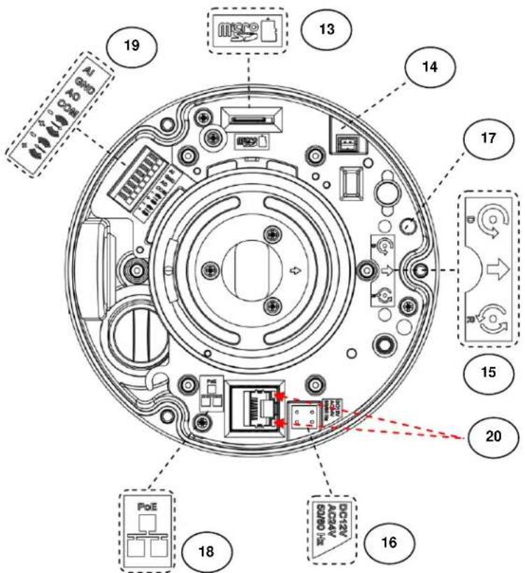
Diagram of a circular device interior with numbered components and labeled parts, including ports like PoE and 18, and a central connector.FIGURE 1-4: CAMERA CONNECTIONS AND FEATURES 3/3
- Micro-SD Card Slot: This slot is for inserting a micro SD card for extra file storage.
NOTE: An SDHC or SDXC card capable of a minimum write speed of 10 MB/sec is recommended for recording HD video. Pelco also recommends the SD card's operating temperature range be suitable for the environment it is intended to be used in.
-
Video Output: The port is used for analog video output. (for IMP531-1ERS only)
-
Default & Reset Button:
Default (D): Press the button for 6 seconds to restore the camera's settings back to the factory default.
- Reset (R): Press the button for below 1 second to reboot the camera.
-
Power Terminal: The port is used to connect with external either DC 12V or AC 24V power supply.
-
Booting Indicators: LED indicator for booting and firmware upgrade (Green/Red/Amber). The LED behavior is:
- Boot Up: LED solid Red. After 2 \~ 3 seconds, then:
- Red to flashing Green if boot up is normal.
- Remains solid Red if an error occurs.
LED turns off 3 minutes after a successful boot.
- Firmware Upgrade: The LED indicator flashing Amber when firmware upgrade is running.
-
RJ-45 Network Port: Connect the RJ-45 connector to this port with a PoE (Class 3) compatible network device that supplies power through the Ethernet cable.
-
Digital I/O Connectors:
- Alarm In: Via "GND" and "AI" ports, connect to external device that can trigger alarm input signals.
- Alarm Out: Via "COM" and "AO" ports, connect to external device to be triggered through alarm output signals.
- Audio In: Via “+” and “-” ports under ⚙️, connect to external device such as microphone that receives sound for camera.
- Audio Out: Via “+” and “-” ports under (1) , connect to device such as speaker to be triggered through alarm output signals.
20. LED Indicators:
- Green LED: With solid green, the LED indicates a live connection is established.
- Orange LED: With flashing orange, the LED indicates data is being transmitted / received between camera and switch.
2. Installation and Connection
2.1 Unpacking Everything
Check all items in the product box against the order form and the packing slip. In addition to this manual, the items below are included in the product box.
- Indoor or Environmental Dome Camera * 1
- Plastic Anchor * 4
● Pan Head Screw (TP4) * 4 - T20 Security Torx Bit * 1
- Mounting Template * 2
● Conduit Hole Rubber Grommet * 1 - Conduit Hole Plug Cover * 1
● Video Out BNC Cable * 1 (only for IMP531-1ERS)
● Supplemental Resources Sheet * 1 - Important Safety Instruction * 1
- ROHS Statement Slip * 1
Please contact your dealer if any items are missing.
2.2 Optional Accessories
- IMP3ICM-1E: Sarix Professional 3 Series Dome In-Ceiling Mount
- IMP3PM-1E: Sarix Professional 3 Series Dome Pendant Mount
- IMP3EBAP: Sarix 4S Electrical Box Adaptor Plate for Surface Mount
- IMP3PMB-1I: Sarix L-Type Bracket for Surface Mount
- WMVE-SW: Wall Mount Arm, 1-1/2" NPT for use with IMP3PM-1E
● PA101: Pole Mount for use with WMVE-SW
● IMP3LD-0E: Smoked Environmental Lower Dome - IMP3LD-0I: Smoked Indoor Lower Dome
- IMP3LD-1E: Clear Environmental Lower Dome
- IMP3LD-1I: Clear Indoor Lower Dome
2.3 Installation
Sarix® Professional 3 Series Dome can be installed by the following method.
- In-Ceiling Flush Mount
- Surface Mount
• Wall or Ceiling Surface Mount
- With L-Type Bracket IMP3PMB-1I
• With Adaptor Plate IMP3EBAP
- Pendant Mount (requires pendant mounting kit)
2.3.1 Checking Appearance
Although the protective materials used for the packaging has been tested to protect the unit from most events during transportation, check the unit and its accessories for any visible damage. Remove the protective film to check items in accordance with the list in 2.1 Unpacking Everything.
2.3.2 Disassembling the Camera
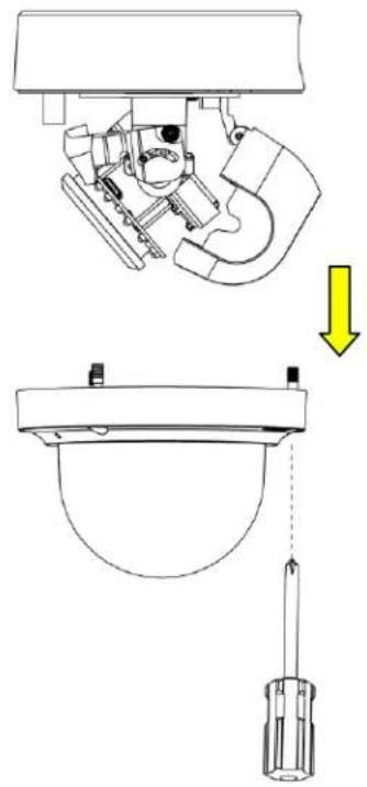
Please refer to the steps in the figure below for correct disassembling order.
- Loosen 3 lower dome screws with the T20 security torx bit (supplied).
- Gently pull lower dome downward to take it apart from the backbox.
- DO NOT remove the camera from the backbox during installation. The camera has been designed to allow for installation without removing camera module from back box.
natural_image
Technical diagram showing a mechanical assembly with a downward arrow indicating a process or transformation (no text or symbols present)FIGURE 2-1: DISASSEMBLING THE CAMERA
2.3.3 Mounting the Camera
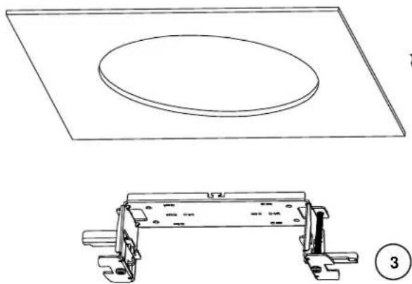
Method 1: In-Ceiling Flush Mount with IMP3ICM-1E
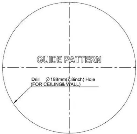
- Use the guide pattern to prepare a mounting area for In-Ceiling Flush Mount.
-
Attach the mounting template on a desired mounting surface (normally for in-ceiling).
-
Drill a round hole ( 198mm) based on the template on the surface to have the camera embedded within the hole later.
text_image
GUIDE PATTERN Drill Ø 198mm(7.8inch) Hole (FOR CEILING& WALL)FIGURE 2-2: MOUNTING TEMPLATE FOR FLUSH MOUNT
-
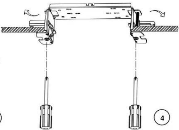
Embed the in-ceiling mount bracket into the hole.
-
Use a cross screw driver to turn the 2 bracket screws clockwise to extend the locking arms and tighten them securely within the in-ceiling area.
natural_image
Technical line drawing of a rectangular plate with an oval cutout and a mechanical bracket assembly (no text or symbols)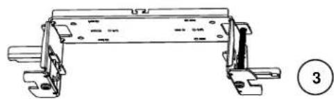
natural_image
Technical line drawing of a mechanical assembly with no visible text or symbolsFIGURE 2-3: IN-CEILING FLUSH MOUNT 1/4
text_image
Technical diagram showing mechanical assembly with labeled components and directional arrows indicating motion or movementFIGURE 2-4: IN-CEILING FLUSH MOUNT 2/4
-
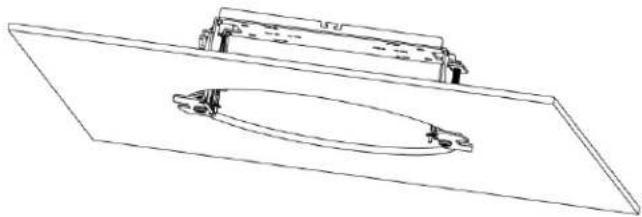
Based on your needs, use the bottom conduit hole or side conduit hole on the backbox for cable entry and feed the cables through the backbox.
-
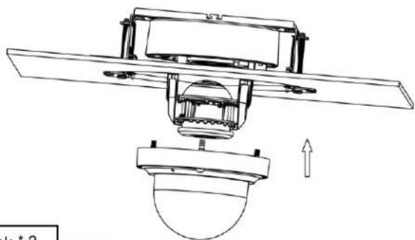
Fix the backbox onto the in-ceiling bracket by fastening the 4 screws (M4X12) followed by aligning the identifying red dots of backbox.
-
Follow 2.3.4 - 2.3.8 before proceeding.
-
Attach the 2 spring hooks of the protective cover to the in-ceiling bracket for mounting completion.
NOTE: For safety reasons, it is strongly recommended that you first ensure the mounting area is stable enough to withstand the in-ceiling bracket and locking arms clamping on it.
natural_image
Technical line drawing of a mechanical component with a circular opening and mounting bracket (no text or symbols)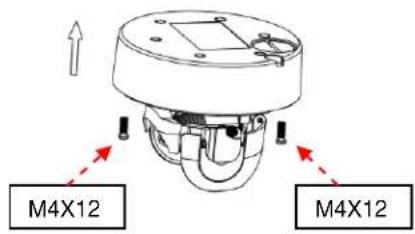
text_image
M4X12 M4X12FIGURE 2-5: IN-CEILING FLUSH MOUNT 3/4
natural_image
Technical line drawing of a mechanical assembly with no visible text or symbols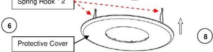
text_image
Spring Hook 2 Protective Cover 6 8FIGURE 2-6: IN-CEILING FLUSH MOUNT 4/4
Method 2: Wall Surface Mount
Wall or Ceiling Surface Mount
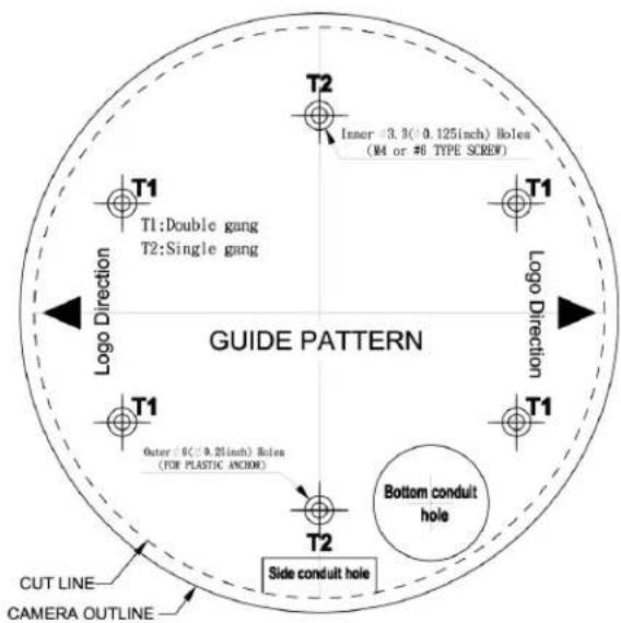
- Use the mounting template to prepare a mounting area for Surface Mount.
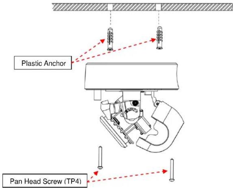
- Place the supplied mounting template on a mounting surface. Drill 6 mm (0.2") outer holes at the T1 or T2 template positions on the mounting surface. Then insert 2 or 4 supplied plastic anchors into the holes
- If you want to feed wiring from the hole on the rear of the backbox, create a circular opening corresponding to the "Bottom conduit hole" of mounting template on the mounting surface.
- If feeding wiring from the side of the backbox, you don't need to drill a hole on the mounting surface. The "Side conduit hole" indication on the mounting template is for user to identify while mounting.
NOTE: Please properly lock the conduit hole plug on the unused hole. For example, lock the side conduit hole with the plug while using the bottom conduit hole for cable entry and vice versa.
text_image
T1 T1:Double gang T2:Single gang T2 Inner 0.3(0.125inch) Bolen (M4 or #6 TYPE SCREW) T1 T1 Logo Direction T1 Outer 0(0.25inch) Bolen (FOR PLASTIC ANCHIE) T2 Side conduit hole Bottom conduit hole CUT LINE CAMERA OUTLINE GUIDE PATTERNFIGURE 2-7: MOUNTING TEMPLATE FOR SURFACE MOUNT
text_image
Plastic Anchor Pan Head Screw (TP4)FIGURE 2-8: WALL OR CEILING SURFACE MOUNT
- Based on your needs, use the bottom or side conduit hole on the backbox for cable entry and feed the cables through the backbox first. Then mount the backbox on a wall surface by securing 4 TP4 screws (supplied) into the inserted plastic anchors tightly.
NOTE:
a. Alternatively, the backbox can be fastened directly to a single gang or double gang electrical box (Fasteners not provided).
b. The mounting height above ground level shall be more than 3 meters for wall mount height.
With L-Type Bracket IMP3PMB-1I
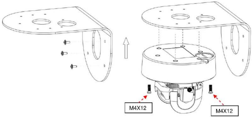
Refer to the figures below for detailed process for Surface Mount with IM3PMB-1I.
NOTE: IM3PMB-11 is NOT provided, and it is mentioned only as additional surface mount for your reference.
text_image
M4X12 M4X12FIGURE 2-9: L-TYPE BRACKET IMP3PMB-1I
FIGURE 2-10: SURFACE MOUNT WITH IMP3PMB-11
- Fasten the L-type bracket onto the desired wall surface with 4 screws.
- Pass all the cable through the L-type bracket.
- Fasten the backbox onto the L-type bracket with 4 screws (M4X12), while feeding the cables through the backbox.
With Adaptor Plate IMP3EBAP
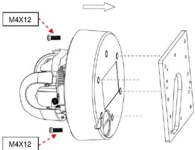
You can mount the camera to a surface with IMP3EBAP, a Sarix 4S electrical box adaptor plate. Refer to the figure below for detailed process for Surface Mount with IMP3EBAP.
NOTE: IMP3EBAP is NOT provided, and it is mentioned only as additional surface mount for your reference.
text_image
M4X12 M4X12FIGURE 2-11: SURFACE MOUNT WITH IMP3EBAP
- Fix the adaptor plate to the surface embedded with a 4S electrical box, single gang electrical box or double gang electrical box (Optional) with 2 or 4 screws.
- Pass all the cable through the adaptor plate and surface.
- Fasten the backbox onto the adaptor plate with 4 screws (M4X12), while feeding the cables through the backbox.
Method 3: Pendant Mount with IMP3PM-1E
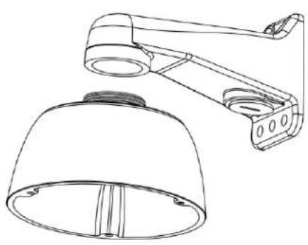
The Pendant Installation involves mounting IMP3PM-1E Sarix Environmental Pendant Mount for indoor or environmental vandal dome camera. Below are the recommended pendant brackets, which are NOT provided, for additional pendant mount applications for your reference.
NOTE: WMVE-SW is NOT provided, and it is mentioned only as an additional mount for your reference.
NOTE: Mounts and conduits must be sealed to prevent condensation in the camera.
CAUTION: Threads may have sharp edges. Handle with care.
natural_image
Technical line drawing of a wall-mounted security camera with a dome-shaped base (no text or symbols)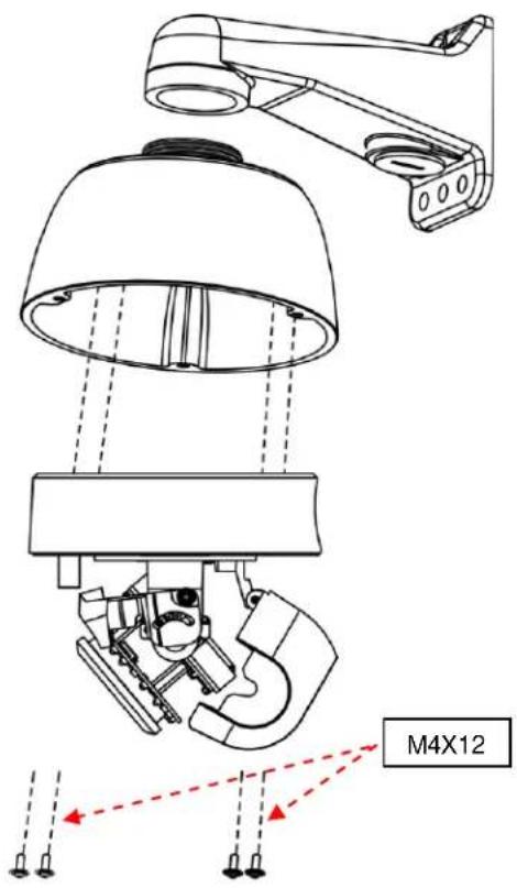
text_image
M4X12FIGURE 2-12: PENDANT MOUNT 1/2
FIGURE 2-13: PENDANT MOUNT 2/2
- Screw the pendant mount back box directly to a female 1-1/2" NPT threaded pipe/fitting or WMVE-SW. Wall mount in a clockwise direction.
- Feed cables through the pendant mount and through the provided grommet. Ensure the rubber grommet is pierced through any of the three locations to feed the cables through.
- Attach the backbox to the pendant mount back box by aligning the red dots for identification of both parts and securely fasten the 4 screws (M4X12), while feeding the cables through the backbox.
2.3.4 Connecting the Cables
The I/O interfaces will be seen on the front of the camera module. Make the appropriate cable connections.
● Power supply via one of the following 3 alternatives.
• AC 24V: Connect a power cable that supplies AC24V power source to the power terminal.
- DC 12V: Connect a power cable that supplies DC12V power source to the power terminal.
NOTE: The polarities should be matching when using DV 12V power source.
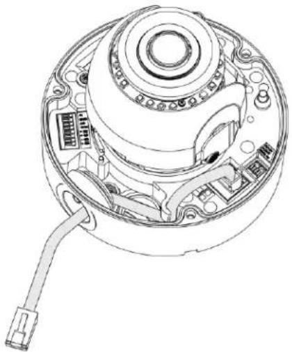
- PoE (Class 3): Connect an Ethernet cable terminated with a short-bodied RJ-45 connector to the PoE RJ-45 port for both power supply and network connectivity purposes simultaneously.
NOTE:
a. Lower dome will not close if you do not use a short-bodied RJ-45 connector.
b. If a Class I PoE adapter or switch is used to provide power, be sure that the power cord is firmly plugged into the socket and confirm the main earth connection.
c. This product is intended to be supplied by a UL Listed Power Adapter or DC power source marked "L.P.S" (or "Limited Power Source"), rated 24Vac, 1.1A or 12Vdc, 1.6A, Tma=50 degree C or 48Vdc, 350mA Gigabit Passive PoE injector, 802.3af/at PSE.
d. Interconnecting cables for PoE is intended to be supplied by a UL Listed type CL3P, CL3R or CL3X, marked "SUNLIGHT RESISTANT", "SUN. RES." or "SR." and "water resistant" or "W".
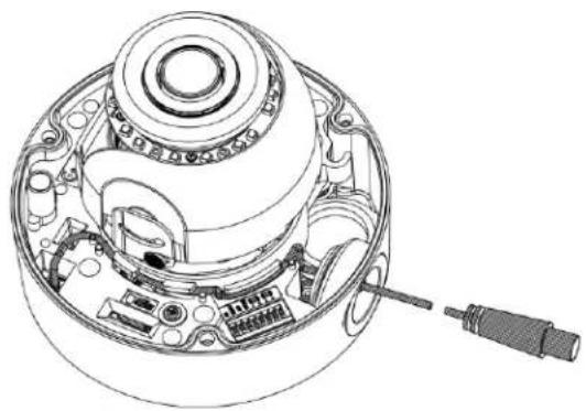
- Connect BNC cable for video output. BNC cable is used to connect to the video input terminal of a monitor, switcher, etc. (to be terminated with 75 ohm impedance)
NOTE: Video output function is supported by IMP531-1ERS only.
- Insert audio in/out cables and alarm in/out cables to the corresponding terminals of the camera if required.
NOTE: It is recommended to connect external microphones to ground (GND) on the digital I/O connector.
● Refer to Figure 1-4: Camera Connections and Features 3/3 for details on I/O interface.
natural_image
Technical line drawing of a mechanical device with internal components and wiring (no text or symbols)FIGURE 2-14: CONNECTING ETHERNET CABLE
natural_image
Technical line drawing of a mechanical device with internal components and a screwdriver (no text or symbols)FIGURE 2-15: CONNECTING BNC CABLE
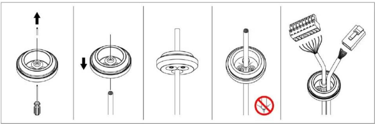
- If using the supplied rubber grommet (recommended), puncture a round hole(s) in the grommet that is smaller than the diameter of the cable that will be passed through the grommet. Feed an unterminated cable through the hole in the grommet. Terminate the cable with the appropriate connector.
text_image
Technical diagram showing five steps of a mechanical assembly with labeled components and a red prohibition symbol.FIGURE 2-16: USING RUBBER GROMMET
2.3.5 Positioning the Camera
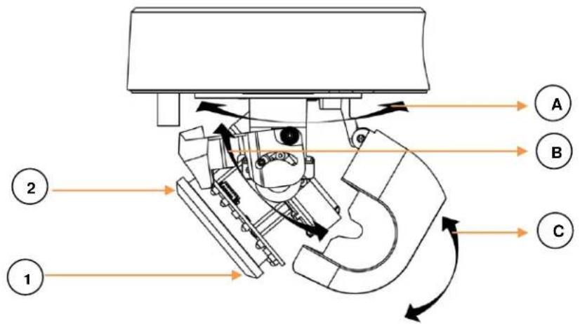
- Pan Adjustment (A): Rotate the lens camera assembly until you are satisfied with the field of view. Note that the side conduit hole of the backbox is the point where the camera lens shouldn't be rotated over.
- Horizontal Rotation (B): Rotate the lens camera assembly in the camera module, but do not turn assembly more than 355° as this may cause the internal cables to be twisted, disconnected, or broken. In addition, pay heed to the location upon which the light sensor (1) is situated since excessive rotation results in, in certain cases, obstruction to light sensor by the IR reflection shield (2). Check the Orientation section in Operations Manual, when 180° above rotation is necessary, for swift orientation adjustment.
- Tilt Adjustment (C): Lift to open the inner liner and tilt the camera lens to your desired angle. Restore the inner liner back to its default position after adjustment.
NOTE: Limitation for three axes position: Pan range: 0°\~370°, Rotate range: 0°\~355°, Tilt range: 15°\~90°.
text_image
Technical diagram of a mechanical assembly with labeled components and directional arrows indicating motion or flow.FIGURE 2-17: POSITIONING THE CAMERA
2.3.6 Adjusting Focus
- View the camera image using the browser (refer to the Operation Manual).
- Use the settings in the Web interface (refer to the Operation Manual) to adjust the zoom and focus of the lens to the desired field of view.
- Also, the focus can be adjusted by moving the zoom slider and using the Focus options in the live webpage.
NOTE: Focus adjustment is done exclusively with Web UI.
2.3.7 Completing the Camera Assembly
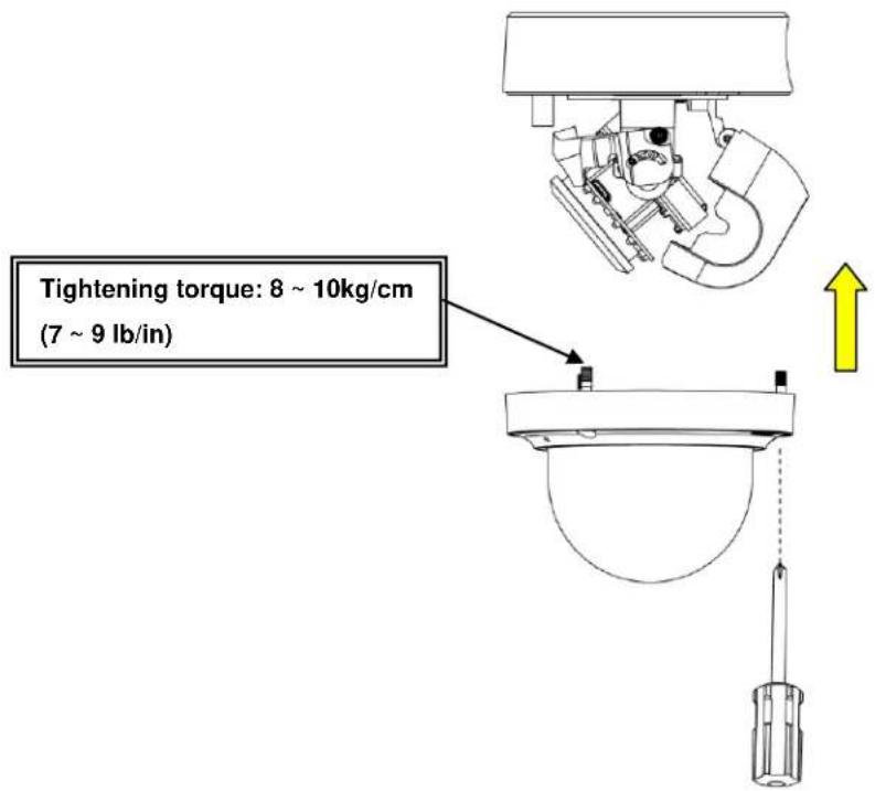
Assemble the lower dome with the backbox, both of which, have red dots for aligning identification, followed by fastening the 3 screws of the lower dome with the T20 security torx bit (supplied) to complete the installation.
NOTE: Suggested tightening torque: 8 \~ 10kg/cm (7 \~ 9 lb/in).
text_image
Tightening torque: 8 ~ 10kg/cm (7 ~ 9 lb/in)FIGURE 2-18: ASSEMBLING THE CAMERA
2.3.8 Lower Dome Defog
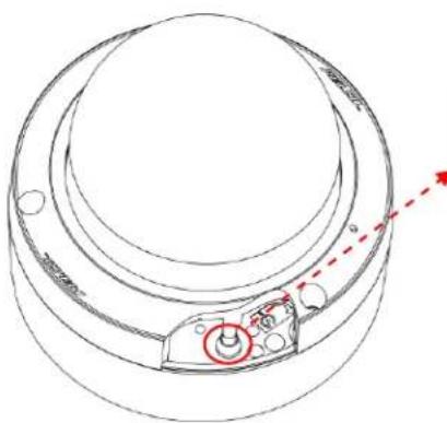
A Defog function, which heats up the camera to overcome certain extreme weather conditions (e.g., snow or frost) which may harm the operation of camera, is embedded within this vandal camera. However, to prevent installers from getting a burn injury, the defog heating function won't be activated when the lower dome is detached from the camera module (as shown in the following figure).
NOTE: Defog function is for IMPX31-1ES/1ERS only.
natural_image
Technical line drawing of a mechanical component with red dashed arrows indicating direction (no text or symbols)Heater is on: salient point is pressed against the button of camera module.
Heater is off: the lower dome is detached from the camera module.
FIGURE 2-19: LOWER DOME DEFOG
Pelco Troubleshooting Contact Information
If the instructions provided fail to solve your problem, contact Pelco Product Support at 1-800-289-9100 (USA and Canada) or
+1-559-292-1981 (international) for assistance. Be sure to have the serial number available when calling.
Do not try to repair the unit yourself. Leave maintenance and repairs to qualified technical personnel only.

This equipment contains electrical or electronic components that must be recycled properly to comply with Directive 2002/96/EC of the European Union -regarding the disposal of waste electrical and electronic equipment (WEEE). Contact your local dealer for procedures for recycling this equipment.
REVISION HISTORY
Manual # Date Comments
C6627M 07/19 Rev.01
PELCO™
Pelco
625 W. Alluvial Fresno, California 93711 United States
(800) 289-9100 USA & Canada Phone
(800) 289-9150 USA & Canada Fax
+1 (559) 292-1981 International Phone
+1 (559) 348-1120 International Fax
www.pelco.com
Pelco, the Pelco logo, and other trademarks associated with Pelco products referred to in this publication are trademarks of Pelco, Inc. or its affiliates. ONVIF and the ONVIF logos are trademarks of ONVIF Inc. All other product names and services are the property of their respective companies. Product specifications and availability are subject to change without notice.
© Copyright 2019, Pelco, Inc. All rights reserved.