Spectra Enhanced S7230L-FW1 - Security Camera Pelco - Free user manual and instructions
Find the device manual for free Spectra Enhanced S7230L-FW1 Pelco in PDF.


User questions about Spectra Enhanced S7230L-FW1 Pelco
0 question about this device. Answer the ones you know or ask your own.
Ask a new question about this device
Download the instructions for your Security Camera in PDF format for free! Find your manual Spectra Enhanced S7230L-FW1 - Pelco and take your electronic device back in hand. On this page are published all the documents necessary for the use of your device. Spectra Enhanced S7230L-FW1 by Pelco.
USER MANUAL Spectra Enhanced S7230L-FW1 Pelco
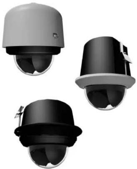
SpectraEnhanced Series7Domes
natural_image
Three identical black-and-white surveillance cameras with dome-shaped lenses, shown from different angles (no text or symbols visible)Dome(S7230L)Models
C6648M(12/19)
Contents
Contents....3
Important Notices 7
Legal Notice 7
Regulatory Notices 7
Warranty Statement 7
Video Quality Caution 7
Open Source Software Notice 7
Description....10
Getting Started 10
System Model Numbers 11
Component Model Numbers 11
Recommended Mounts 11
Dome Camera Models....12
Supplied Parts List: In-Ceiling system 12
User-Supplied Parts List: In-Ceiling System....12
Supplied Parts List: Pendant system 12
User-Supplied Parts List: Pendant 12
Product Overview....13
Installation Methods....13
Installation (Back Box) 14
Installing the Back Box (In-Ceiling)....14
Installing the Back Box (Pendant)....15
Installation (Dome Drive)....17
Installing the Dome Drive (In-Ceiling)....17
Installing the Dome Drive (Pendant)....18
Installation (Lower Dome) 20
Installing the Lower Dome (In-Ceiling/Indoor) 20
Installing the Lower Dome (In-Ceiling/Environmental) 20
Installing the Lower Dome (Environmental Pendant) 21
Ethernet Wiring Requirement for POE 802.3bt 23
Accessing the Camera 24
Supplemental Resources 24
Pelco Troubleshooting contact information 24
LEGALNOTICE
SOMEPELCOEQUIPMENTCONTAINS,ANDTHESOFTWAREENABLES,AUDIO/VISUALANDRECORDINGCAPABILITIES,THEIMPROPERUSEOF WHICHMAYSUBJECTYOUTOCIVILANDCRIMINALPENALTIES.APPLICABLELAWSREGARDINGTHEUSEOFSUCHCAPABILITIESVARY BETWEENJURISDICTIONSANDMAYREQUIRE,AMONGOTHERTHINGS,EXPRESSWRITTENCONSENTFROMRECORDEDSUBJECTS.YOU ARESOLELYRESPONSIBLEFORINSURINGSTRICTCOMPLIANCEWITHSUCHLAWSANDFORSTRICTADHERENCETOANY/ALLRIGHTSOF PRIVACYANDPERSONALTY.USEOFTHISEQUIPMENTAND/ORSOFTWAREFORILLEGALSURVEILLANCEORMONITORINGSHALLBEDEEMED UNAUTHORIZEDUSEINVIOLATIONOFTHEENDUSERSOFTWAREAGREEMENTANDRESULTINTHEIMMEDIATETERMINATIONOFYOUR LICENSERIGHTSTHEREUNDER.
REGULATORYNOTICES
This device complies with Part 15 of the FCC Rules. Operation is subject to the following two conditions: (1) this device may not cause harmful interference, and (2) this device must accept any interference received, including interference that may cause undesired operation.
RADIOANDTELEVISIONINTERFERENCE
This equipment has been tested and found to comply with the limits of a Class A digital device, pursuant to Part 15 of the FCC rules. These limits are designed to provide reasonable protection against harmful interference when the equipment is operated in a commercial environment. This equipment generates, uses, and can radiate radio frequency energy and, if not installed and used in accordance with the instruction manual, may cause harmful interference to radio communications. Operation of this equipment in a residential area is likely to cause harmful interference in which case the user will be required to correct the interference at this own expense.
Changes and Modifications not expressly approved by the manufacturer or registrant of this equipment can void your authority to operate this equipment under Federal Communications Commission's rules.
CANICES-3(A)/NMB-3(A)
KOREANCLASSAEMC
For information about Pelco's product warranty and thereto related information, refer to www.pelco.com/warranty.
VIDEOQUALITYCAUTION
FrameRateNoticeRegardingUser-SelectedOptions
Pelco systems are capable of providing high quality video for both live viewing and playback. However, the systems can be used in lower quality modes, which can degrade picture quality, to allow for a slower rate of data transfer and to reduce the amount of video data stored. The picture quality can be degraded by either lowering the resolution, reducing the picture rate, or both. A picture degraded by having a reduced resolution may result in an image that is less clear or even indiscernible. A picture degraded by reducing the picture rate has fewer frames per second, which can result in images that appear to jump or move more quickly than normal during playback. Lower frame rates may result in a key event not being recorded by the system.
Judgment as to the suitability of the products for users' purposes is solely the users' responsibility. Users shall determine the suitability of the products for their own intended application, picture rate and picture quality. In the event users intend to use the video for evidentiary purposes in a judicial proceeding or otherwise, users should consult with their attorney regarding any particular requirements for such use.
OPENSOURCESOFTWARENOTICE
This product includes certain open source or other software originated from third parties that is subject to the GNU General Public License (GPL), GNU Library/Lesser General Public License (LGPL) and different and/or additional copyright licenses, disclaimers, and notices.
The exact terms of GPL, LGPL, and some other licenses are provided to you with this product. Please refer to the exact terms of the GPL and LGPL at http://www.fsf.org (Free Software Foundation) or http://www.opensource.org (Open Source Initiative) regarding your rights under said license. You may obtain a complete corresponding machine-readable copy of the source code of such software under the GPL or LGPL by sending your request to digitalsupport@pelco.com; the subject line should read Source Code Request. You will then receive an email with a link for you to downloadthesourcecode.
This offer is valid for a period of three (3) years from the date of the distribution of this product by Pelco.
NOTE: This product is intended to be supplied by a Listed Power Adapter or DC power source marked "L.P.S." (or "Limited Power Source"), rated 48Vdc, 1.9A, 24Vac (50/60 Hz), 4.8A or POE BT, 1.3A, Tma = 60 degree C, and the altitude of operation = 2000m. If you need further assistance with purchasing the powersource, please contact to PELCO, INC for further information.
Description
The Spectra Enhanced Series 7 high speed IP PTZ dome cameras provide top tier image quality, performance, and intelligent embedded features for state-of-the-art surveillance solutions. There are several different form factors including in-ceiling and pendant domes with different configurations (e.g. indoor, environmental). All environmental models feature a robust design with aluminum construction and an IK10 rated housing and polycarbonate bubble. The environmental models feature worry-free use in harsh environments with IP66, IP67, and Type 4X ratings, andawiderangeofoperatingtemperatures.
The Spectra Enhanced Series 7 dome camera is easy to install, offers flexible mounting options, and uses a standard Web browser for easy remotesetupandadministration.
The Spectra Enhanced Series 7 dome camera easily connects to Pelco IP and hybrid systems such as VideoXpert and Digital Sentry version 7.3 (or later). The camera also conforms with ONVIF Profile S, Profile G, Profile Q, and Profile T for connection with third-party software. Pelco offers an ApplicationProgrammingInterface(API)andSoftwareDeveloper'sKit(SDK)forinterfacingwithPelco'sIPcameras.
This document describes the installation and initial setup procedures to begin operating the camera. For more information about operating your camera, refertotheoperationmanualspecifictotheproduct.
NOTE: For additional information about Spectra Enhanced Series 7 dome product documentation in English and other languages, go to www.pelco.comandnavigatetotheSpectraEnhancedSeries7website.
GETTINGSTARTED
• Before installing your device, thoroughly familiarize yourself with the information in the installation section of this manual.
• Pelco recommends connecting the device to a network that uses a Dynamic Host Configuration Protocol (DHCP) server to address devices.
- Donotuseanetworkhubwhenconfiguringthenetworksettingsforthedevice.
- Toensuresecureaccess, placethedevicebehindafirewallwhenitisconnectedtoanetwork.
SYSTEMMODELNUMBERS
| Type | BackBox Color | LowerDomeSystem Resolution | ModelNumberDescription |
| In-ceiling,IndoorBlack | Smoked2MP30XS7230L-FW0SpectraEnhancedDome | 1080p | |
| Clear2MP30XS7230L-FW1SpectraEnhancedDome | 1080p | ||
| In-ceiling,EnvironmentalBlack | Smoked2MP30XS7230L-YB0SpectraEnhancedDome | 1080p | |
| Clear2MP30XS7230L-YB1SpectraEnhancedDome | 1080p | ||
| Pendant,EnvironmentalWhite | Smoked2MP30XS7230L-EW0SpectraEnhancedDome | 1080p | |
| Clear2MP30XS7230L-EW1SpectraEnhancedDome | 1080p | ||
| Pendant,EnvironmentalBlack | Smoked2MP30XS7230L-EB0SpectraEnhancedDome | 1080p | |
| Clear2MP30XS7230L-EB1SpectraEnhancedDome | 1080p |
COMPONENTMODELNUMBERS
| Back Box | HighDefinition(HD)LowerDome* | DomeDrive | |||
| B7-F | In-ceiling Indoor | LD7F-0 | Indoor, White, Smoked, 1080p | D7230L | 30X |
| B7-F-Eln-ceilingEnvironmental | LD7F-1 | Indoor,White,Clear,1080p | |||
| B7-PW-E | Pendant Environmental, White | LD7PB-0 | Environmental, Black, Smoked, 1080p | ||
| B7-PB-EPendantEnvironmental,BlackLD7PB-1 | Environmental,Black,Clear,1080p | ||||
*Use the pendant lower domes with the environmental in-ceiling and environmental pendant back boxes.
RECOMMENDEDMOUNTS
| PendantDomes | |
| IWM-SWWallmount,whitefinish;canbeadaptedforcorner,parapet,orpoleapplication | |
| IWM24-SW Series | Wallmount,withintegral24VAC,100VAtransformer;whitefinish;canbeadaptedforcorner,parapet,or poleapplication |
| PP350/PP351 | Parapetwall/roofmount |
| SWM Series | Compact wall mount, white or black finish; can be adapted for corner or pole applications |
SUPPLIEDPARTSLIST:IN-CEILINGSYSTEM
QtyDescription
1Backboxwithmountinghardware
1Lowerdome(includestrimringandbubble)
1Domedrive
1Mountingtemplate
118-pinterminalblock
12-pinterminalblock
1Metalplugandnut
1 Safetybracket
1Rubbergrommet(Environmentalln-Ceilingmodelsonly)
1 Installationmanual
1 Important Safety Instructionsdocument
USER-SUPPLIEDPARTSLIST:IN-CEILINGSYSTEM
In addition to the standard tools and cables required for a video security installation, you will need to provide the following items:
QtyDescription
1 Safetychain
1Conduitfittingandnut
1Cat5e(orhigher)cable
SUPPLIEDPARTSLIST:PENDANTSYSTEM
QtyDescription
1Pendantbackbox
1Lowerdome(includestrimringandbubble)
1Domedrive
118-pinterminalblock
12-pinterminalblock
1Waterproofgland
1 Anti-seizelubricant
1Installationmanual
1 Important Safety Instructionsdocument
USER-SUPPLIEDPARTSLIST:PENDANT
In addition to the standard tools and cables required for a video security installation, you will need to provide the following items:
QtyDescription
1PendantMount
1Cat5e(orhigher)cable
text_image
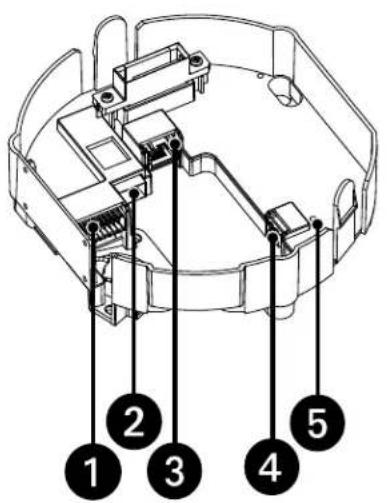
Technical diagram of a device with numbered components labeled 1 through 5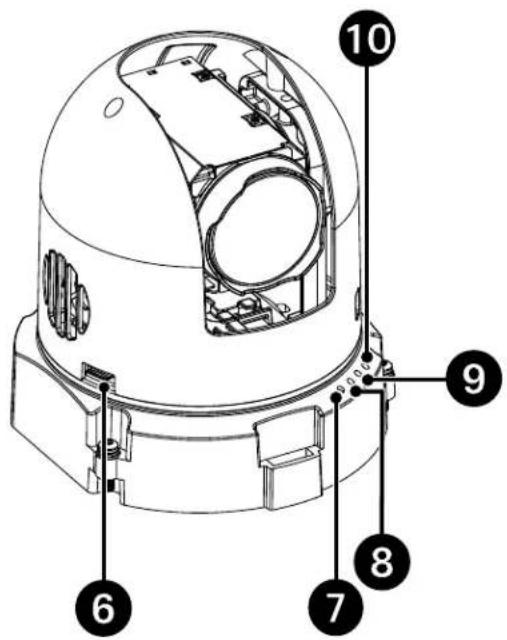
text_image
Technical diagram of a mechanical device with numbered components for identificationFigure1.SpectraEnhancedSeries7DomeCamera
| #Connection/FeatureDescription | |
| 1Alarm,Relay,andAudio In/Out | An18-pinconnectorwithfoulararms,tworelay,andaudioinandout. |
| 2SFPPort | ConnectstheSFPmodule.Theportwillauto-detecteither100Mbpsor1Gbpsspeeds.EnsurethesamespeedSFPis beingusedontheothersideofthelink. |
| 3 RJ-45 Network Port | Connects the camera to the IP network and supplies power to the camera through the network using Power overEthernet(802.3bt).802.3btmustbeusedtopowerallapplications. |
| 4PowerTerminal | The port is used to connect with either a 48 VDC or 24 VAC power supply. Use 16 to 20 AWG gage wire.NOTE: There isnopolarityforthepowerconnection. |
| 5PowerLEDThisLEDglowssolidgreenwhenthepowerison.TheLEDisoffwhenthereisnopower. | |
| 6MicroSDCardSlotSlotforremovableMicroSDCardforflashmemory. | |
| 7 Reset Button | Reboots the camera or restores the camera's factory default settings. This button is recessed. Using a small tool,suchasapaperclip,pressandreleasetheResetbuttonfor1secondtorebootthecamera.Pressandhold theResetbuttonfor10secondstorestorethecameratothefactorydefaultsettings. |
| 8 Status LED | Powers up solid amber. Blinks green when motors start to calibrate and during boot-up. Blinks amber during a firmwareupdate.Solidgreenduringnormaloperation(ifLEDsareONintheuserinterface). |
| 9 Ethernet Link/Activity LED | LED blinks green while the camera boots and link is active. After boot completed the LED is OFF. |
| 10SFP/ActivityLEDBlinksgreenwhilethecamerabootsandlinkisactive.AfterbootcompletedtheLEDisOFF. | |
INSTALLATIONMETHODS
YoucaninstalltheSpectraEnhancedSeriesdomesystemusingoneofthefollowingmethods:
• Installationinasuspendedceilingorafixedceiling.
• Installation using apendantmount(not supplied).
INSTALLINGTHEBACKBOX(IN-CEILING)
-
Locatethecenterpointofthemountinglocation.
-
Use the supplied mounting template to attach to the ceiling.
3.Cutoutaroundthemountingtemplate.
-
Attachaconduitfitting(notsupplied)andlocknut(notsupplied).
-
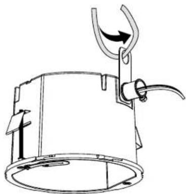
Install a safety chain/cable (not supplied) to the safety chain bracket. The safety chain/cable should be capable of supporting up to 7.3 kg (16 lb).
natural_image
Technical line drawing of a mechanical device with a curved hook and lever mechanism (no text or symbols)Figure2.SafetyChain
-
Pull the wiring into the back box through the conduit fitting. NOTE: For environmental in-ceiling models installed in air handling spaces, use the supplied metal plug and nut. All other installation environments may use either the supplied rubber grommet plug or metal plug with nut.
-
Installthebackbox:
a. Compressthespringclipsandpushthebackboxthroughthehole. b. Tightenthescrewsuntilyouhearaclickingnoise.
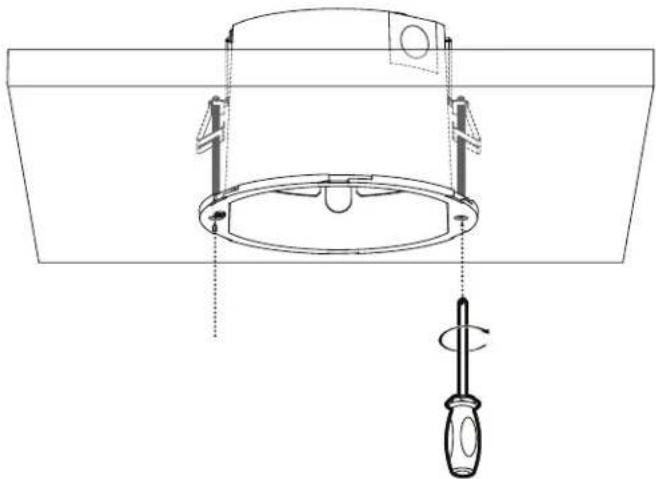
natural_image
Technical line drawing of a ceiling lamp fixture with screwdriver and mounting bracket (no text or symbols)Figure3. InstallingtheBackBox: In-CeilingModels
- Connect the power wiring. Referto the figure below and the Wiring topic form more information.
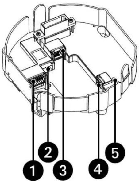
text_image
Technical diagram of a device casing with numbered components labeled 1 through 5Figure4.WiringConnections
| #Connection/FeatureDescription | |
| 1Alarm,Relay,andAudio In/Out | An18-pinconnectorwithonealarm,onerelay,andaudioinandout. |
| 2SFPPort | ConnectstheSFPmodule.Theportwillauto-detecteither100Mbpsor1Gbpsspeeds.EnsurethesamespeedSFPis beingusedontheothersideofthelink. |
| 3 RJ-45 Network Port | Connects the camera to the IP network and supplies power to the camera through the network using Power overEthernet(802.3bt).802.3btmustbeusedtopowerallapplications. |
| 4PowerTerminal | Theportisusedtoconnectwitheithera48VDCor24VACpowersupply.Use16to20AWGgagewire.NOTE:Thereisnopolarityforthepowerconnection. |
| 5PowerLEDThisLEDglowssolid | greenwhenthepowerison.TheLEDisoffwhenthereisnopower. |
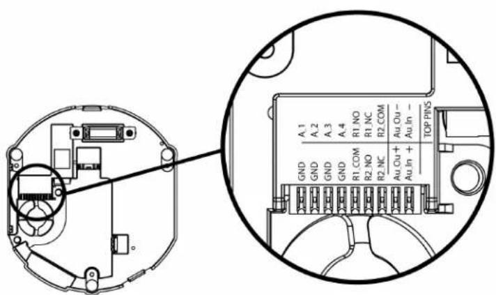
text_image
A.1 A.2 A.3 A.4 GND GND GND R1 NO R1 NC R2 COM Au Cu - Au In + TOP PINS R1 COM R2 NO R2 MC Au Cu + Au In + +Figure5. Alarm, Relays, and Audio Pins
- Install the pendant mount (not supplied). Referto the instruction supplied with themount.
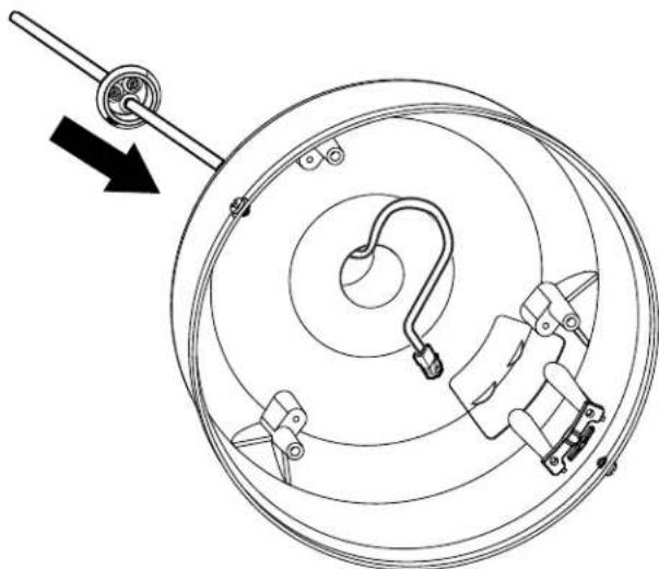
- Pull the wiring into the backbox and through the supplied waterproof gland.
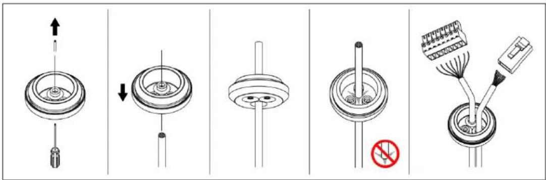
text_image
Technical diagram showing five different mechanical or electrical component assembly steps with directional arrows and a no-smoking symbol.Figure6.Grommet
natural_image
Technical diagram of a mechanical assembly with concentric circles and a lever, showing no text or symbols.Figure7.PullingtheWiringintotheBackBox
- Screwthebackboxontothependantmountandapplythreadcompound(supplied)tothethreadsonthebackbox.
NOTE: Thread compound must be applied on both standard and environmental pendants. Not doing so may prevent the units from being separated in the future.
- Connect the power wiring. Referto Figure 4 and the Wiring section form more information.
INSTALLINGTHEDOMEDRIVE(IN-CEILING)
-
Lineuptheedgesofthedomedrivewiththeinsideofthebackbox.
-
Push the dome drive into the clips until both sides click into place. The clips temporarily hold the dome drive in place.
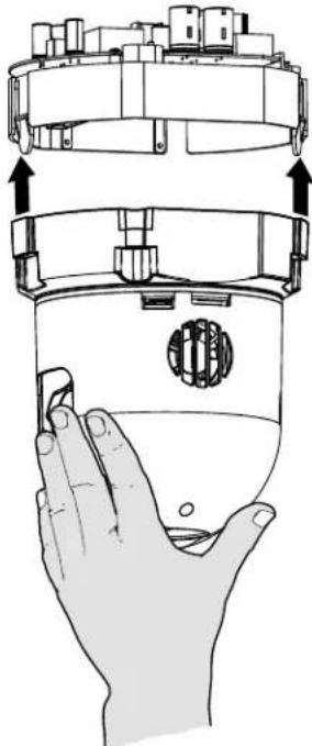
natural_image
Illustration of a hand holding a transparent container with a circular component, showing mechanical components above (no text or symbols)Figure8. InstallingtheDomeDrive
-
Placeonehandonorunderthedomeuntilthefastenersaresecure.
-
Screwin the threee captive fasteners until they are secure.
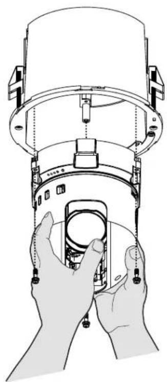
natural_image
Illustration of hands assembling or adjusting a cylindrical device with a circular component inside (no text or symbols visible)Figure9. Installing the Dome Drive: In-Ceiling Models
natural_image
Diagram of a mechanical device with a lever and clamping mechanism, no text or symbols presentFigure10. DomeDrivewithGrommetInstalledonBack
-
Lineuptheedgesofthedomedrivewiththeinsideofthebackbox.
-
Push the dome drive into the clips until both sides click into place. The clips temporarily hold the dome drive in place.
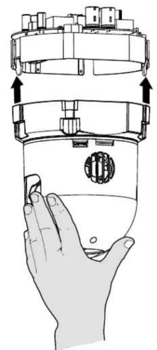
natural_image
Illustration of a hand holding a device with a circular component, showing internal components and directional arrows (no text or symbols)Figure11.InstallingtheDomeDrive
- Placeonehandonorunderthedomeuntilthefastenersaresecure.
- Screwin the threee captive fasteners until they are secure.
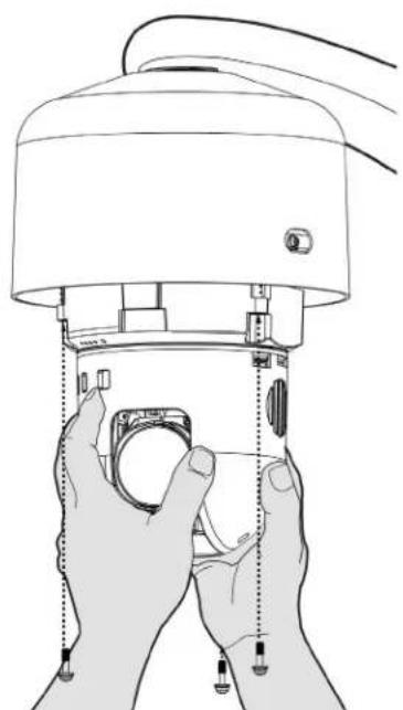
natural_image
Line drawing of hands assembling or adjusting a mechanical device with a circular component (no text or symbols)Figure12. Installing the Dome Drive: Pendant Models
INSTALLINGTHELOWERDOME(IN-CEILING/INDOOR)
- Attachthebackboxleashtothelowerdome.
- Turn counter clockwise until the dome is nestled into the gaps in the back box. Then turn a little clockwise to secure.
- Alignthedomearrowswiththearrowsonthebaseandthenusea15to20degreeclockwiseturntosecure.
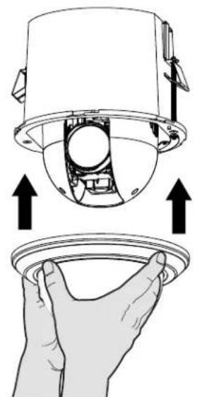
natural_image
Diagram showing a hand holding a device with arrows indicating upward motion (no text or symbols present)Figure13. Placing the Lower Dome: In-Ceiling Indoor Models
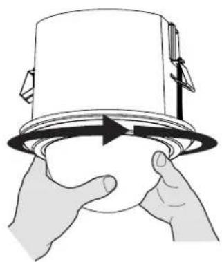
natural_image
Illustration of hands holding a cup with a circular arrow indicating rotation (no text or symbols)Figure14. Tightening the Lower Dome: In-Ceiling Indoor Models
- Applypowertothedome. Thedomesystemwillcompleteaconfigurationsequence.
INSTALLINGTHELOWERDOME(IN-CEILING/ENVIRONMENTAL)
- Attachthebackboxleashtothelowerdome.
- Alignthebackboxscrewswiththeslotsonthelowerdome.
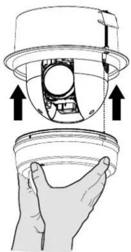
natural_image
Diagram showing a hand holding a camera lens and a sensor or camera module, with no visible text or symbols.Figure15.PlacingtheLowerDome:In-CeilingEnvironmentalModels
- Pushthelowerdomeontothebackbox.
- Tightenthescrewstosecurethelowerdometothebackbox.
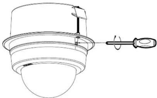
natural_image
Technical line drawing of a mechanical component with a rotating shaft and housing (no text or symbols)Figure16. Tightening the Lower Dome: In-Ceiling Environmental Models
- Applypowertothedome. Thedomesystemwillcompleteaconfigurationsequence.
INSTALLINGTHELOWERDOME(ENVIRONMENTALPENDANT)
- Attachthebackboxleashtothelowerdome.
- Alignthebackboxscrewswiththeslotsonthelowerdome.
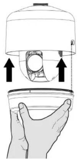
natural_image
Illustration of a hand holding a container with an upward arrow indicating motion or force (no text or symbols present)Figure17.PlacingtheLowerDome:PendantModels
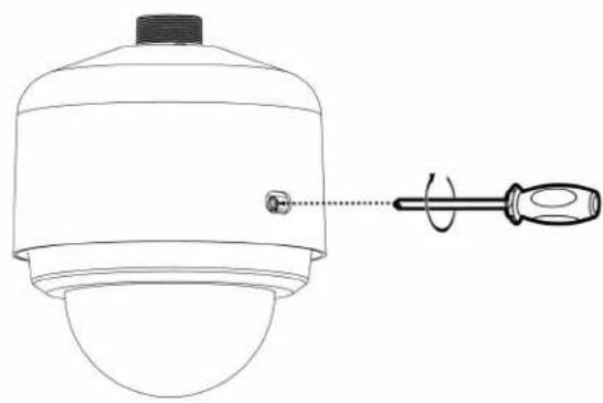
natural_image
Technical line drawing of a mechanical component with a screwdriver inserted, no text or symbols presentFigure18. Tightening the Lower Dome: Pendant Models
- Applypowertothedome. Thedomesystemwillcompleteaconfigurationsequence.
Connect a Cast5e cable or higher cable (not supplied) to the RJ-45 network connector. the 8-pin port includes video over Ethernet, and PoE 802.3bt for the camera. PoE 802.3bt injects power over the same cabling that carries the network data, eliminating the need for a separate power supply. This simplifiesthe installation and operation of the camera without affecting network performance.
Figure19.PinNumbering
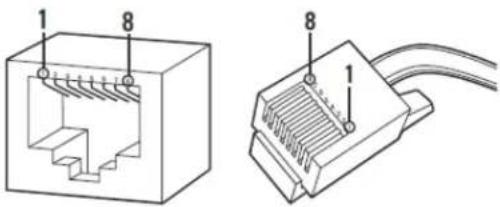
text_image
Technical diagram of a Ethernet connector showing internal structure and cable connection detailsFigure20.PinFunctions
| PairsPair1Pair2Pair3Pair4 | ||||
| Pins1and23and64and57and6 | ||||
| SignalAssignmentBI_DA+/BI_DA-BI_DB+/BI_D | B-BI_DC+/BI_DC-BI_DD+/BI_DD- | |||
| Valid4-pairPowerConfigurations | N | P | N | |
| N | P | P | ||
| P | N | N | ||
| P | N | P | ||
| Ndenotesapairconnectedtonegativepotential.Pdenotesapairconnectedtopositivepotential. | ||||
N
Anyone who access the camera can view live video. If you want to prevent users from viewing video without logging in, you must change the permissionsforpublicusers.
The recommended browsers for your camera are the latest version of Internet Explorer®, Microsoft™ Edge™, Google Chrome™ browser, or Mozilla® Firefox®. for supported browserversions, refertothespecificationsheet.
1.Openawebbrowser.
- Typethecamera'sIPaddress(192.168.0.20)orhostnameinyourbrowser'saddressbar,andthepressEnter.
NOTE: You can obtain your camera's IP address or access the camera using the Pelco Device Utility or VxToolbox software. If DHCP is enabled but a DHCP server is not on the network, the camera automatically assigns itself both an IPv4 link local address (169.254.x.x, where the lower two octets are random) and a 192.168.0.20 address. Additional cameras will assign themselves different IPv4 link local addresses and the next available 192.168.0xIP addresses in sequential order. For example, if three cameras are connected to a network without a DHCP server, the first camera to connect assigns itself the IP address 192.168.0.20, the second camera assigns itself 192.168.0.21, and the third camera assigns itself 192.168.0.22.
3.ClickLogin.
- If needed, type your username and password.
NOTE: For security purposes, it is recommended that you create a user account when you login to the camera for the first time.
- In its out-of-the-box configuration, the camera has no user name and password assigned. For security purposes, it is recommended that you set an administrative user name and password after initial configuration of the camera. Creation of an administrative user name changes the state of the camera to its “operational mode,” where credentials must be provided in order to change its configuration.
- There is no provision for recovering a forgotten administrator user name or password. The camera can be restored to its out-of-the-box, no-password configuration by powering down, depressing the Factory Defaults button, and holding the button down for at least four seconds whilepowerthecamerabackup.
- Ifausernameandpasswordexist,aLoginlinkappearsintheupperrightareaofyourwebbrowser.
5.ClickLogIn.
SUPPLEMENTALRESOURCES
All Spectra Enhanced Series 7 supplemental resources (e.g. firmware, documentation, VxToolbox, and Device Utility) are available in one location: www.pelco.com/spectra-enhanced-7
PELCOTROUBLESHOOTINGCONTACTINFORMATION
If the instructions provided fail to solve your problem, contact Pelco Product Support at 1-800-289-9100 (USA and Canada) or +1-559-292-1981 (international)forassistance.Besuretohavetheserialnumberavailablewhencalling.
Donottrytorepairtheunityyourself.Leavemaintenanceandrepairstoqualifiedtechnicalpersonnelonly.
REVISIONHISTORY
Manual#DateComments
C6648M12/19Originalversion.
Pelco, the Pelco logo, and other trademarks associated with Pelco products referred to in this publication are trademarks of Pelco, Inc. or its affiliates.
ONVIF and the ONVIF logo are trademarks of ONVIF Inc. All other product names and services are the property of their respective companies.
Productspecificationsandavailabilityaresubjecttochangewithoutnotice.
© Copyright 2019, Pelco, Inc.
All rights reserved.
PELCO™
Pelco, Inc. 625W. Alluvial Fresno, California 93711 United States
USA&CanadaTel(800)289-9100Fax(800)289-9150
InternationalTel+1(559)292-1981Fax+1(559)348-1120
www.pelco.com