VideoXpert Professional VXP-P2-72-J-D - Security Camera Pelco - Free user manual and instructions
Find the device manual for free VideoXpert Professional VXP-P2-72-J-D Pelco in PDF.


User questions about VideoXpert Professional VXP-P2-72-J-D Pelco
0 question about this device. Answer the ones you know or ask your own.
Ask a new question about this device
Download the instructions for your Security Camera in PDF format for free! Find your manual VideoXpert Professional VXP-P2-72-J-D - Pelco and take your electronic device back in hand. On this page are published all the documents necessary for the use of your device. VideoXpert Professional VXP-P2-72-J-D by Pelco.
USER MANUAL VideoXpert Professional VXP-P2-72-J-D Pelco
Publication date: 09/20
Table of Contents
Using VideoXpert Toolbox 8
Performing Initial VideoXpert Server™ Configuration Using VxToolbox™ 8
Logging Out 10
Changing the VxToolbox™ Password 11
Licensing Your System 12....
Viewing the License Summary.12.... 13 Adding and Renewing Licenses....
Manually Activating Licenses.... 13 Automatically Activating Licenses.... 14
Installing Entitlements After Restoring Your System.... 15
Managing the System.... 16
Adding a VX System™ 16
Editing the System Validation.... 16
Removing a System.... 17
Discovering Devices 18
Finding Devices (Quick Discovery).18..... Finding and Adding Devices (Quick Discovery and Add).... 18
Finding Devices (Advanced Discovery).... 18
Adding an RTSP Device.... 19
Recognizing Device Credentials.... 19
Adding Credentials for Devices that Require Authentication.... 20
Creating a Default User on Cameras That Have No User 20
Resetting the Password on a Storage Device.... 20
Licensing and Configuring a Camera for the Pelco Advanced Analytics Suite™ 21
Managing Devices on a System.... 25
Adding and Commissioning Devices 25
Adding Devices Without Commissioning.... 26
Commissioning Devices that were Added Previously.... 26
Decommissioning Devices 26
Replacing a Camera.... 26
Removing Devices.... 27
Adding Video Associations.... 27
Viewing Devices, Data Sources, Alarms & Relays, or Access Points 29
Finding and Filtering Existing Sources 30
Controlling the Columns Displayed in the Devices Window 30
Viewing the License Summary 30
Viewing and Configuring Device Information 30
Disabling and Enabling Data Sources 34
Configuring the Rules Engine.... 35
Managing Rules 35
Managing Triggers 36
Managing Schedules 38
Managing Responses.... 40
Configuring Recording 44
Configuring a Recorder 44
Viewing Cameras Assigned to a Recorder 45
Adding a Recording Group to a Recorder 45
Creating a Recording Schedule for a Recording Group 45.
Creating a Bump on Alarm Recording Schedule 47
Editing a Recording Group 47
Editing a Recording Schedule 48
Deleting a Recording Group 49
Deleting a Recording Schedule 49
Deleting a Recording Behavior (Trigger) 49
Managing Users and Roles 51
Understanding Internal and Restricted User Accounts 51
Creating a Role 51
Editing a Role....52
Duplicating a Role 53
Deleting a Role 53
Viewing Details of a Role 53
Adding Users 53
Editing Users 54
Searching for Users 54
Assigning Roles 55
Resetting Passwords 55
Setting the User Password Expiration Policy 55
Deleting Users....56
Configuring VideoXpert System™ Settings 57
Configuring General Settings for VideoXpert Professional™ Systems 57
Configuring Authentication 58
Configuring System Backups 63
Backing Up and Restoring the Database on VideoXpert Professional™ Systems 64
Configuring the SMTP Server 65
Controlling Memory Usage 66
Configuring Monitor Walls 67
Creating a Monitor Wall 67
Editing a Monitor Wall 68
Deleting a Monitor Wall 68
Using Send Video Permissions.... 69
Using Reports....70
Creating a Report Template 70
Editing a Report Template 71
Deleting a Report Template 71
Generating a Report Manually 72
Exporting a Generated Report 72
Deleting a Generated Report 72
Managing Events 73
Finding and Filtering Events 73
Viewing and Configuring Event Details 73
Viewing and Configuring Event Notifications 74
Using Maps™ 76
Preparing Your System for Maps 76.
Creating a New Map..76.
Viewing an Existing Map 77
Editing an Existing Map..77.
Deleting an Existing Map 77
Managing Permissions for Maps 77.
Using VideoXpert Portal and VideoXpert Storage Portal 78
Using VxPortal™ 78
Accessing VxPortal™ 79
Configuring a Browser to Enable Single Sign-On in VxPortal™ 79
Changing the System Password in VxPortal™ 80
Viewing Video Sources and Bookmarks in VxPortal™ 80
Managing Exports 80
Configuring the Server 81
Viewing Keyboard Shortcuts 82
Logging Out 82
Configuring Advanced Storage Using VideoXpert Storage Portal™ 82
Accessing the VideoXpert Storage Portal™ 82
Checking VideoXpert Storage™ Status 82
Generating and Downloading Storage Logs 82
Configuring the Server in VideoXpert Storage Portal™ 82
Managing Database Backups 83
Using Volume Groups and Volumes 83
Viewing Storage Assignments 87
Selecting All Data on a Tab 87
Printing Data from a Tab 87
Reading Aloud 87
Changing the Password 87
Logging Out 88
Using VideoXpert OpsCenter 89
Configuring VxOpsCenter™ 89
Running the Application for the First Time 89
Setting Up Your VideoXpert Workstation™ 90
Reconfiguring Your VideoXpert Workstation™ 92
Configuring VX System™ Connections 93
Configuring Shared Display™ Mode 98
Configuring VxOpsCenter™ Kiosk Mode (Optional) 101
Logging In 102
Understanding User Account Types 102
Setting Your Display Language 102
Changing Your Workstation Account Password 104
Using the VxOpsCenter™ Interface 105
Adding Quick Access Icons to Mission Control 106
Using Context Menus 106
Using Tooltips 107
Using Watched By 108
Setting User Preferences 108
Using Tabs and Workspaces 112
Using Tab View Options and Modes 112
Configuring Tab View Options 112
Changing Tab Modes 113
Creating a New Tab 113
Opening a Saved Tab 114
Updating an Existing Tab 114
Changing Tab Layouts 114
Editing the Metadata of an Existing Tab 114
Deleting a Saved Tab from the System.... 115
Creating a New Workspace 115
Opening a Saved Workspace 115
Updating a Saved Workspace 116
Editing the Metadata of an Existing Workspace 116
Deleting a Workspace from the System 116
Viewing a Monitor Wall 117
Working with Maps™ 118
Understanding Maps Permissions.... 118
Viewing a Map.... 118
Working In a Map.... 118
Setting User Preferences for Maps 119
Sending Views to Workstations™ or Shared Displays™ 120
Using View Launcher to Send Views to Workstations™ or Shared Displays™ 120
Using Quick Launch to Send Cells to Workstations™ or Shared Displays™ 121
Watching Video 122
Understanding Cell Borders 123
Responding to an Alarm in a Cell 123
Rotating the Camera 124
Viewing Analytics Overlays 124
Enabling and Disabling Audio 125
Expanding a Cell to Full-Screen 125
Watching Recorded Video With VideoXpert™ 126
Watching Recorded Video with Edge Storage™ 126
Using Pixel Search™ 126
Using Bookmarks 127
Synchronizing Video Playback 128
Creating a Live Sequence Mode 129
Creating an Alarm Sequence Mode 130
Editing Sequences 131
Pausing and Resuming Sequences 131
Setting up Snapshots 131
Taking Snapshots 131
Displaying Statistics 132
Measuring Latency 132
Viewing and Filtering Sources 133
Managing Tags 134
Playback Controls 136
Controlling Cameras (PTZ) 137
Using Quick Export 140
Using Investigation Mode 143
Entering Investigation Mode 143
Using Investigation to View Video Stored on a Camera's Local Storage 143
Using Auto-backfill Recording Gaps 144
Creating Clips 145
Creating a Playlist 145
Previewing and Editing Playlists.... 145
Exporting a Playlist 146
Encrypting Export Files 147
Using the Export Archive 148
Previewing Exports 148
Downloading Exports 148
Getting the Password for an Encrypted Export 149
Editing an Export Name 149
Deleting One or More Exports 149
Working with Plugins 151
Installing Plugins 151
Adding a Plugin to Your Workstation 151
Installing and Using the BriefCam Plugin™ 151
Using the Event Viewer™ Plugin 152
Using the Image Viewer™ Plugin 152
Using the Web Browser Plugin 153
Using the Access Control System Viewer Plugin™ (Optional) 153
Using the VideoXpert Plates™ ALPR Plugin 156
Closing a Plugin 161
Responding to Events 162
Using the Event Viewer 162
Using the Event Notifications Dialog Box 162
Logging Out 164
Closing the Application 165
Appendix A: Working With Permissions 166
Understanding Permission Resource Restrictions 166
Using Supervision and Reports Permissions 166
Using Device Management Permissions 167
Using User Management Permissions 167
Using Event Management Permissions 168
Using System Management Permissions 168
Using Surveillance Permissions 169
Using Investigation Permissions 169
Using VideoXpert Toolbox
Performing Initial VideoXpert Server™ Configuration Using VxToolbox™
VideoXpert Professional™ comes with a time-limited trial license. During this trial, you have access to all VideoXpert features, and you can ignore the Licensing tab within VideoXpert.
To use VideoXpert beyond the trial, you must apply a license to the server. Licensing requires either an Internet connection on the VideoXpert server itself, or access to a separate computer with Internet access.
- After installing VideoXpert, click Configure or run VxToolbox for the first time on your VideoXpert (VX) System™.
- For VideoXpert Professional systems, in the VideoXpert Basic System Setup dialog box, type values in the Company Name and Name Your System fields, and then click Save.
- Perform the steps in the section titled Configuring General Settings for VideoXpert Professional™ Systems.
- Perform the steps in the section titled Adding a VX System™.
- To set the VxToolbox password:
a. Click the menu icon (☐), and then click Set VxToolbox Password.
b. Type a value in the Password and Reset Password fields.
c. Click Save.
- To set the VxToolbox password and login requirements:
a. Set the password for the admin user on your system.
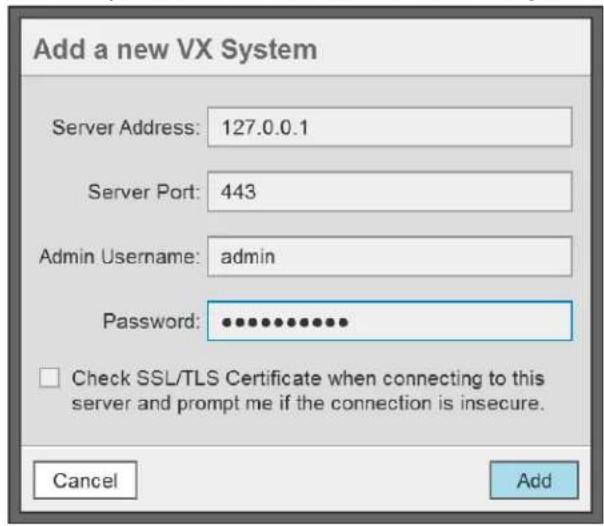
text_image
Add a new VX System Server Address: 127.0.0.1 Server Port: 443 Admin Username: admin Password: •••••••••••• □ Check SSL/TLS Certificate when connecting to this server and prompt me if the connection is insecure. Cancel Add
Note: The default user name admin. You must set a new password.
b. (Optional) Click to select the checkbox to ensure that the system checks the SSL/TLS Certificate when connecting to the server.
Enable this feature if your organization uses signed HTTPS certificates and the certificate has already been loaded using VxToolBox.
c. Click Add.
d. In the VxToolbox Password Confirmation Window, click Set Password (recommended) or No Thanks.
e. If you clicked Set Password, in the Set VxToolbox Password dialog box, enter a password in the Password and Retype Password fields, and then click Save.
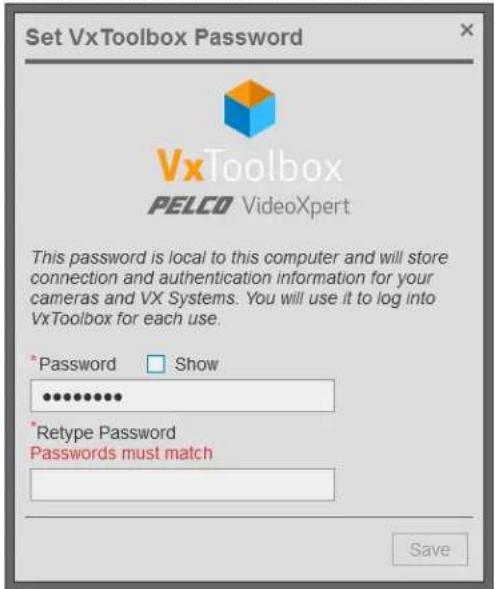
text_image
Set VxToolbox Password VxToolbox PELCO VideoXpert This password is local to this computer and will store connection and authentication information for your cameras and VX Systems. You will use it to log into VxToolbox for each use. * Password Show ••••••••• * Retype Password Passwords must match Savef. In the Configure VxToolbox dialog box, click OK.
g. If you enabled SSL/TLS Certificate checking, you might be required to interact with more dialog boxes. If so, follow the prompts.
h. In the Configuration Required dialog box, enter a Company Name. This is the name by which the Pelco licensing portal will recognize your VX server. The name cannot be changed later.
i. Click Save & Continue.
The VxToolbox application opens.
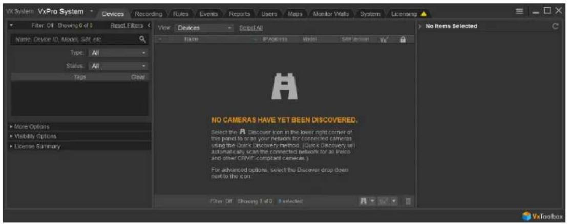
text_image
VX System VxPro System Devices Recording Rules Events Reports Users Maps Monitor Walls System Licensing Filter Off Showing 0 of 0 Reset Filters View Devices Select All Name: Device ID: Makers SUN site Type: All Status: All Tags Clear More Options Visibility Options License Summary NO CAMERAS HAVE YET BEEN DISCOVERED. Select the A Discover icon in the lower right corner of this panel to scan your network for connected cameras using the Quick Discovery method. (Quick Discovery will automatically scan the connected network for all Palco and other OHME-compliant cameras.) For advanced options, select the Discover drop down next to the icon. Filter Off Showing 0 of 0 selected No Items Selected VxToolboxLogging Out
- Click the menu icon( ), and then click Exit.
- In the Exit confirmation dialog box, click Exit.
Changing the VxToolbox™ Password
When starting VxToolbox, the application requests credentials. These credentials are local to the workstation and your VxToolbox installation; they do not log you in to any system or camera. Rather, your VxToolbox credentials protect your settings and the credentials for the individual cameras and systems you want to access from other users on the same workstation.
After logging in to VxToolbox, you can add systems with independent credentials, and pass credentials to cameras requiring them (closed authentication or third-party cameras).
Because your local VxToolbox environment may connect you to multiple systems and cameras, it is recommended that you protect your credentials and log out when you have finished using the application.
To change your VxToolbox password:
- Click the menu icon (☐), and then select Change VxToolbox Password.
- In the Account Settings dialog box, enter a new password in the New Password and Confirm New Password fields, and then click Save Changes.
Licensing Your System
VideoXpert is licensed for the system, for upgrades, and by channel—the video streams you view and record. It comes with one (1) license to start. A Lite license (VideoXpert Professional only) has four (4) channels. The demo license provides unlimited channels that are active for a period of 60 days. These are active only the first time you install the software, or if the software was pre-installed, the first time you start up the system. In order for the system to function beyond the evaluation period, add the appropriate quantity of licenses to the system.
You can license the system automatically or manually.
- Manual licensing allows you to license a system that does not have an Internet connection. See the section titled Manually Activating Licenses
- Automatic licensing requires your VideoXpert system to be connected to the Internet and have access to the Pelco licensing server. See the section titled Automatically Activating Licenses.
If one or more licenses associated with the VideoXpert system are nearing or past the expiration date and require renewal, a warning dialog box will open. The dialog box lists the affected license(s) and the expiration date.

Note: You can also view your current licenses at any time. See section titled Viewing the License Summary.
For assistance, contact Pelco Product Support at 1-800-289-9100 (USA and Canada) or+1-559-292-1981 (international).
Viewing the License Summary
Entitlements are associated with licenses. A license might be a consolidation of several entitlements. To view licenses:
- Open VxToolbox and click the Licensing tab.
- In the License Summary table (bottom panel), view the list of licenses. For each license:
- The license Name is listed. Unactivated Entitlements are listed as one license with the name Pending. The names in the License Summary table correspond to the names in the Entitlements table.
- The Total column lists how many licenses and channels (sources) are included.
- The In Use column identifies how many of the licenses and channels are in use.
- The Remaining column identifies how many of the licenses and channels are not currently in use.
- The Expiration Date column identifies when the licenses will expire.
If one or more licenses are nearing expiration, three warning icons appear in the Licensing Summary area of the Licensing page:
- On the right of the Licensing tab, itself
• In the left panel of the License Summary area, to the left of the license Name - When the license is selected, in the top of the Transaction History (right) panel of the License Summary area
Hover over any of these warning icons to display relevant information.
Click Details, if present, to display License Extension Details for [license name]:
- View the current SUP expiration information, the number of channels on the VX System, and information about extending the SUP.
- If the SUP is expiring soon, instruct the system to use existing information to build an estimated price quote. If the necessary system variables cannot be retrieved, a default message is displayed instead of a quote.
- Click OK to close the dialog box.
For assistance, contact Pelco Product Support at 1-800-289-9100 (USA and Canada) or +1-559-292-1981 (international).
Adding and Renewing Licenses
When you are notified that one or more licenses are expiring or have expired, when you see the warnings in the License Summary area of the Licensing page, purchase a Software Update Plan (SUP).
- SUPs are purchased in units of "channel-years".
• One channel-year represents the use of one (1) licensed channel for one (1) year. - Channel-years are usually purchased in such a way as to allow each channel on the system to be licensed for a period of several years.
For example: a system with 40 channels will need to purchase 80 channel-years to extend the SUP by two (2) years.
- Integration licenses are combined to provide the longest time before expiration.
For example: where appropriate, two one-year integration licenses will be recognized as a single license that expires in two (2) years.
- Adding channels to or removing channels from the system adjusts the expiration date of the
licenses to reflect how long it will take the connected channels to use the remaining channel-years. - If your licenses expired before you renew them, part of your SUP is used to backfill the period of
time when the previous SUP/licenses had lapsed.
When licenses expire, all associated features are disabled until new licenses are installed or until the existing licenses are renewed. If the SUP has expired, you cannot upgrade the system until the SUP is purchased or renewed.
For assistance, contact Pelco Product Support at 1-800-289-9100 (USA and Canada) or +1-559-292-1981 (international).
Manually Activating Licenses
For manual licensing, you must have your activation ID and a separate computer with access to the licensing server at http://licensing.pelco.com. During the manual licensing process, you will need to transfer your Licensing Request File to a computer with Internet access during the activation process. If you received multiple activation IDs for VideoXpert products, you must complete the process below for each individual activation ID.
As a part of this process, you will download an Entitlement Request File and a Entitlement File; both files are specific to the product for which they were requested. It is recommended that you rename both files to reflect the system for which they are intended to prevent confusion during the licensing process.
- Open VxToolbox and click the Licensing tab.
- At the lower right corner of the Entitlements table (top panel), click the Add License icon (+).
- Enter your activation ID in the Activation ID box.
-
If necessary, click to deselect the checkbox to Automatically activate online.
-
You will be prompted to save an activation request .bin file. Select a folder (optional) type in a file name, and then click Save.
An Entitlement Request File (named either what you typed in or the same name as the Activation ID) with a .bin extension is downloaded to your computer. -
Click Enter.
-
The Entitlement Pending status message appears at the top of the Entitlements table.
-
An entitlement named Pending will be listed in the table. At the far right of the Pending entitlement row will be two icons: Download a new request (.bin) file (☐) and Remove this activation ID☒().
-
On a system connected to the Internet, open a new browser window or tab and go to the Pelco licensing server at http://licensing.pelco.com.
-
Under Login, click to select logging in With User Name, With Entitlement Id, or With Activation Id. You can also register as a New User.
-
Enter your credentials, and then click Login to access the Pelco licensing server.
-
Click the Manage Devices tab, and then click Generate License. Upload the request bin file to the licensing web site. The Entitlement File, named response.bin, will be downloaded to your computer.
-
Click the Licensing tab to return to the Licensing page within VxToolbox.
-
Click Choose file under the Entitlements section.
-
Select your Entitlement File (response.bin), and then click Open.
-
Click Import License File.
When the process is complete, VxToolbox will display the installed license(s) in the Entitlements table.
Automatically Activating Licenses
If your system has an active Internet connection with access to http://licensing.pelco.com, you can automatically activate licenses for your system.
- Open VxToolbox and click the Licensing tab.
- At the lower right corner of the Entitlements table (top panel), click the Add License icon (+).
- Enter your activation ID in the Activation ID box.
-
If necessary, click to select the checkbox to Automatically activate online.
-
Click Enter.
The system logs in to the Pelco licensing server and performs several tasks. Do not navigate away from this page until you see the Add License dialog box.
- Click OK.
VxToolbox will display the installed license(s) in the Entitlements table.
Installing Entitlements After Restoring Your System
Pelco highly recommends that you back up your system and save the response file used to apply your initial entitlement.
- If restoring your system after uninstalling VideoXpert, you can re-apply your initial entitlement or license.
- If you re-image your system, you cannot apply your previous entitlement. If you have re-imaged your system, contact Pelco Product Support at 1-800-289-9100 (USA and Canada) or+1-559-292-1981 (international) for assistance.
Managing the System
VxToolbox provides a single interface from which to manage and configure both cameras and your VideoXpert Systems. From VxToolbox, you can manage any system that you can access by IP address or hostname.
Selecting a system (by name) from the VX System menu allows you to configure that system; the settings you see are relevant to the system, and any discovery operations you perform are issued directly from that system.
Use the VX System menu to switch between various VideoXpert systems.
Adding a VX System™
VxToolbox allows you to administer systems remotely. To add a system to VxToolbox, you must have network access to the system and your user account must be assigned the administrative role.
- Access the Add a new VX System dialog box by one of these methods:
- If the Add a new VX System dialog box opens automatically, and the VxToolbox Password Confirmation Window also opens automatically, click Set Password, enter the new password in the fields, and then click Save.
- Click the menu icon ( ) at the upper right corner of the window, click Manage VX System Connections, and then click the Add a new VX System icon (+).
- At the upper left corner of the window, use the VX System drop-down menu to select Add a VX system.
-
Enter an IP address in the Server Address field.
-
Enter a value in the Server Port field, or use the default port.
-
Enter the Admin Username and Password for the system you are adding.
-
If an SSL/TLS certificate has been uploaded and configured, click to select the checkbox for Check SSL/TLS Certificate... to validate the certificate.
-
Click Add.
-
If necessary, click the ✗ at the top left of the Manage VX System Connections window to close it.
Editing the System Validation
You can change whether the SSL/TLS certificate is validated when connecting to a system from VxToolbox. Editing a system only affects your settings within your local VxToolbox installation.
-
Click the menu icon (☐) at the upper right corner of the window, and then click Manage Vx System Connections.
-
Select the system you want to edit.
-
In the right panel of the Manage Vx System Connections window, view the system connection information.
-
Click the Edit VX System icon ( ) to edit system settings.
a. Enter the Admin Username.
b. Enter the Password.
c. Click to select or deselect the checkbox for Check SSL/TLS Certificate...
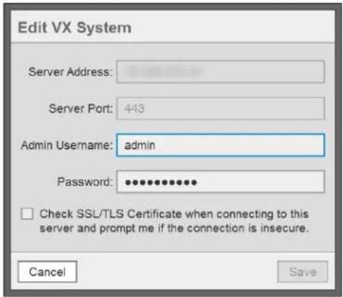
text_image
Edit VX System Server Address: Server Port: 443 Admin Username: admin Password: •••••••••••• □ Check SSL/TLS Certificate when connecting to this server and prompt me if the connection is insecure. Cancel Save- Click Save.
- In the Update dialog box, click OK.
- Click the ✗ at the top left of the Manage VX System Connections window to close it.
Removing a System
You can remove a system from VxToolbox. It can be re-added at any time.
- Click the menu icon (☐) at the upper right corner of the window, and then click Manage Vx System Connections.
- Select the system you want to remove.
- Click the Delete icon() to remove the system.
- In the Delete System dialog box, click OK to confirm the deletion.
- Click the ✗ at the top left of the Manage VX System Connections window to close it.
Discovering Devices
VxToolbox can search the local network or the network belonging to any particular VideoXpert system for devices, or you can add devices manually to the VxToolbox list. Through VxToolbox, you can manage device settings for all the devices on the network, without having to go to individual device interfaces.
VxToolbox can discover Pelco cameras or third-party cameras supporting ONVIF.

Note: You must be connected to a VideoXpert system to add devices to the system.
Finding Devices (Quick Discovery)
Use Quick Discovery to discover devices, but not add them. If you use Quick Discovery, you must add devices manually. Alternatively, use the Quick Discovery and Add option described in the section titled Finding and Adding Devices (Quick Discovery and Add).
To use Quick Discovery, click Devices, and then do one of the following:
- Click the Quick Discovery icon (A) to perform a quick search for devices.
- Click the Advanced Discovery Options icon (▼) to the right of the Quick Discovery icon, and then click Quick Discovery.
- Click the Advanced Discovery Options icon (▼) to the right of the Quick Discovery icon, and then click Advanced Discovery. In the Discover Network Devices dialog box, in the Discovery Method field, select Discover by IP or Hostname from the drop-down menu. Specify the Host address, and then click Discover.
Finding and Adding Devices (Quick Discovery and Add)
- Click Devices, and then click the Advanced Discovery Options icon (▼) to the right of the Quick Discovery icon.
- Click Quick Discovery and Add.
All Devices and Data Sources that are discovered by VxToolbox are added to the VX System to which you are connected.
- If the Recorder Assignment dialog box opens, assign the third-party devices to a recorder.
a. Select an option from the Select Recorder drop-down menu.
b. Click Add.
c. If the devices cannot be added to the VX System, the Operation Failure dialog box opens. Make a note of the information in the box, click OK, and then try to add the devices to a different recorder. If necessary, contact Pelco Customer Support.
Finding Devices (Advanced Discovery)
Using Advanced Discovery, you can search for devices by protocol type or you can add individual devices by IP address. You may want to add devices that do not support ONVIF or Pelco discovery methods using the IP address.
- Click Devices, and then click the Advanced Discovery Options icon (▼) to the right of the Quick Discovery icon.
-
Click Advanced Discovery.
-
To use Quick Discovery, but specify using either SSDP (Simple Service Discovery Protocol) or WS-Discovery (Web Services Dynamic Discovery):
a. From the Discovery Method drop-down menu, select Quick Discovery.
b. Click to select or deselect the checkbox for SSDP.
c. Click to select or deselect the checkbox for WS-Discovery.
d. (Optional) Click to select the checkbox for Add discovered devices to the VX system.
- If you want to discover devices by IP address or hostname:
a. From the Discovery Method drop-down menu, select Discover by IP or Hostname.
b. Enter a value in the Host field.
c. (Optional) Enter a value in the HTTP Port field.
d. (Optional) Type values in the Username and Password fields.
e. (Optional) Select a value from the Driver drop-down menu.
f. (Optional) Click Add Host Address, and repeat the previous three steps.
g. (Optional) Click to select the checkbox for Add discovered devices to the VX system.
- Click Discover.

Note: While this feature adds devices to the system, it does not commission them. To commission the devices, add them, then select them, right-click a device that is selected, and then click Commission.
Adding an RTSP Device
To add a device that uses RTSP:
- Click Devices, and then click the Advanced Discovery Options icon (▼) to the right of the Quick Discovery icon.
- Click Add RTSP Device.
- Type a value in the Device Name field.
- (Optional) Click to select the checkbox for Set Credentials, and then enter values in the Username and Password fields.
- Enter a value in the URI field.
- (Optional) Click Add Another URI to this Device, and then enter a value in the URI field.
- When you have added all URIs, click Create.
Recognizing Device Credentials
Some devices require credentials for you to access their video or change their settings. The Authentication Status column provides the status of each device.
Table 1: Icons in the Authentication Status column
| Icon | Description |
| Device requires authentication. | |
| Device does not require authentication. | |
| VxToolbox has authenticated to this device. | |
| This device is authenticated in VxToolbox, but not on the system with which it is assoClick the icon to attempt to authenticate the device with the system. | |
| This device is authenticated on a particular system with which it is associated, but not VxToolbox. You must first authenticate to view and/or edit the device. | |
| The user must be created on the camera before accessing the camera |
Adding Credentials for Devices that Require Authentication
To add credentials to a device:
- Click Devices.
- Select the device requiring credentials.
- Enter credentials in the appropriate fields, and then click Submit.
Creating a Default User on Cameras That Have No User
For security purposes, cameras require a user to be created on the camera before the VideoXpert system can access the camera.
- Add a camera using Quick Discovery or Advanced Discovery. See Finding Devices (Quick Discovery) or Finding Devices (Advanced Discovery).
- In the main panel of the Devices page, locate any cameras on the VideoXpert System that have a warning icon (⚠️) to the left of the camera Name and the locked camera icon (◀️) in the Authentication Status column.
- If necessary, refer to the camera instructions and add the user to the camera.
- Select the camera for which a user must be created.
- Enter credentials in the appropriate fields, and then click Submit.
- Add and commission the camera. See Adding and Commissioning Devices.
Resetting the Password on a Storage Device
You must reset a password on a storage device before you can use it.
- Add a storage device using Quick Discovery or Advanced Discovery. See Finding Devices (Quick Discovery) or Finding Devices (Advanced Discovery).
- In the list of devices, find a storage device with a locked server icon ( ) to the left of the device name and a warning icon (⚠️) in the Authentication Status column, and then click to select the device.
- In the right panel, enter the credentials to reset the password, and then click Reset Password. A password must be at least eight characters long.
You can now add and commission the storage device. See Adding and Commissioning Devices.
Licensing and Configuring a Camera for the Pelco Advanced Analytics Suite™
When you discover a camera that supports advanced analytics, you must commission the device before you can apply a license and use advanced analytics.
Licensing the Camera for the Pelco Advanced Analytics Suite™
To license the camera:
- Connect to a VX System.
- Discover and commission the device. See the sections titled Finding and Adding Devices (Quick Discovery and Add) and Commissioning Devices that were Added Previously
- Click the Devices tab.
- In the center panel of the Devices page, select the camera for which you want to see analytics.
- In the right panel, click to expand Analytics, and then under ADVANCED ANALYTICS, click Apply a license.
- If the No License Remaining dialog box opens, click OK. If the dialog box does not open, skip to step 12.
- Purchase a new license.
- Click the Licensing tab, and follow the instructions in the section titled Manually Activating Licenses or Automatically Activating Licenses for adding a license for the camera.
- Click the Devices tab.
- In the center panel of the Devices page, select the camera for which you want to see analytics.
- In the right panel, click to expand Analytics, and then under ADVANCED ANALYTICS, click Apply a license.
- In the Apply Analytics License dialog box, click Apply.
Configuring a Camera for the Pelco Advanced Analytics Suite™
To configure the camera:
- Click the Devices tab.
-
Click the Edit icon (☐) to the right of ADVANCED ANALYTICS in the right panel to open the Configure Advanced Analytics for [device name] dialog box.
-
(Optional) For a PTZ camera, in the left panel:
a. Select a PTZ preset from the drop-down menu.
b. (Optional) Set a Confidence Threshold, by either using the slider bar, or typing a value in the % field.
A confidence threshold filters out object detections that have a confidence percentage lower than the threshold value. This is useful for filtering out detections that are not people or vehicles, or to help better detect objects at further distances. To filter objects out you can increase the threshold. To increase the distance of detections you can decrease the threshold.
- In the Configure Advanced Analytics for [device name] dialog box, configure the zones or counters.
a. To create a New analytic rule, in the Analytic Rules (left) panel, click the add icon (+), and then select the type of zone or counter to add.

Note: If you are configuring a Counterflow zone, see the section understanding Counterflow zones
b. To configure a Person in Zone or a Vehicle In Zone area, in the center panel:
- To reshape, expand, and/or move the zone (polygon with a blue or orange border—blue for person, and orange for vehicle), click and drag it or its points.
- To create a new point on the box, click the left mouse button. Drag the point to the appropriate location.
- To delete a point on the box, click the right mouse button on the point, and then click Delete Point.
- If there is a detection issue (for example: the analytics do not detect a person in the zone), change the size, shape, and position of the zone until detection is working as expected.
c. To configure a Person Counterflow or a Vehicle Counterflow area, in the center panel:
- To reshape, expand, and/or move the zone (polygon with a blue or orange border—blue for person, and orange for vehicle), click and drag it or its points.
- To create a new point on the box, click the left mouse button. Drag the point to the appropriate location.
- To delete a point on the box, click the right mouse button on the point, and then click Delete Point.
- If there is a detection issue (for example: the analytics do not detect a person in the zone), change the size, shape, and position of the zone until detection is working as expected.
d. To configure a Person Counter or a Vehicle Counter, in the center panel:
- Drag the counter line (blue or orange line—blue for person, and orange for vehicle) from the upper left corner of the center panel to the appropriate location.
- To shorten, lengthen, and or/move the line, click and drag it or its end points.
- If there is a detection issue, change the size, angle, and position of the line until detection is working as expected.
e. To name or rename a zone, click to select the zone name in the right panel, and then enter a new string in the Zone Name field in the left panel.

Note: Do not use quotation marks in the zone name.
f. In the right panel, enable or disable the zone by clicking to select or deselect the checkbox for Zone is Enabled.
g. (Optional) For zones, but not for counters, in the right panel, click to select the checkbox for Override Default Severity, and then set a new severity value, either by moving the slider bar or typing a number in the field.
h. For counterflow zones, select the Counterflow Angle, either by typing in a number or by selecting it using the slider bar.
i. For counter lines:
- Click to select the appropriate type of line from the Counter Type drop-down menu. This applies only to the line currently selected.
- An Uni-Directional Line counts objects that cross the line in the configured direction. It has one or more white arrows on the line pointing in one direction.
- A Bi-Directional Line maintains two separate counts—one for each direction that an object crosses the line. For example they can be used for a building entrance to differentiate between the number of people entering and exiting a building. It has one or more white arrows pointing in one direction; each is paired with a black arrow on the line pointing to the opposite direction.
- An Omni-Directional Line counts when objects cross the line from any direction that is not parallel to the line. It has one or more white diamonds—two white arrows pointing in opposite directions from the line.
- (Optional) If you clicked Bi-Directional Line, you can either maintain the Direction Labels as they are, or you can type in new labels for each arrow type. This applies only to the line currently selected.
j. To save current settings before making more modifications or adding another zone, click Apply Changes.
k. To edit a zone or counter, click to select the zone or counter in the left panel; and then change any of the setting that are available in the right panel.
I. (Optional) To delete a zone, do one of the following:
- Click to select the zone name in the left panel, click the Delete selected analytic zones icon (☐), and then click OK in the Delete Zones confirmation dialog box.
- Right-click the zone border or the counter line, click Delete Analytic Rule, and then click OK in the Delete Analytic Rules dialog box.
m. Click Save & Close.

You can disconnect from a VX System and still configure the zones.
Understanding Counterflow zones
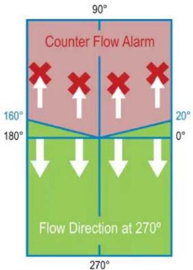
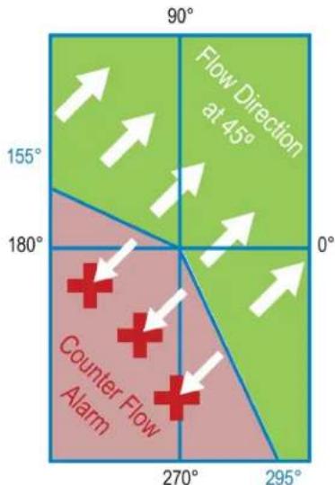
Counterflow alarms are triggered when the angle between an object's trajectory and the wrong direction is greater-than 110 degrees.
In Figure 1: Counterflow at 90 degrees, the Counterflow arrow is pointing at 90 degrees. Alarms trigger when the angle is between 20 and 160 degrees.
text_image
Counter Flow Alarm 160° 180° 20° 0° Flow Direction at 270° 90°Figure 1: Counterflow at 90 degrees
In Figure 2: Counterflow at 135 degrees, the Counterflow arrow pointing at 135 degrees. Alarms trigger when the angle is between 155 and 245 degrees.
text_image
90° Flow Direction at 45° 155° 0° 180° Counter Flow Alarm 270° 295°Figure 2: Counterflow at 135 degrees
Managing Devices on a System
You must add a device to VideoXpert to make it visible within the system and to manipulate device settings. VxToolbox enables you to add a device or change device settings.
You must commission a device to view its video or to use its video or resources within VideoXpert. VideoXpert typically commissions devices automatically when you add them to the system. In many cases, commissioning a device requires a license; the type of license required depends on the type of device you are commissioning.
Add or commission operations are available from the Devices tab for the selected system. Commissioning information is shown in the Added/Commissioned ( ) column; you can expose this column by selecting Added/Commissioned from Show Data Columns in the filtering panel.
Table 2: Icons in the Added/Commissioned column
| Icon | Status |
| NOT added to the system | |
| Added to the system, but not commissioned | |
| Added; commissioned |
Adding and Commissioning Devices
VxToolbox will only provide adding and commissioning options applicable to the camera(s) you have selected. Add and Commission operations are relevant to the system you have selected from the VX System menu.
- In the center panel of the Devices tab, select the devices you want to add and commission.
-
Perform one of the following steps:
-
Right-click the device, and then select Add and Commission to [VX System name].
- Click to select the device, and then click the Add, Commission, and Assign Cameras to a recorder icon V_x at the lower right of the center panel.
-
Click to select the device, click the Addition, Commission and Assignment options icon (▼), and then click Add and Commission to [VX System name].
-
If the Authentication Notice dialog box opens, follow the instructions in the dialog box.
- If the Recorder Assignment dialog box opens, select a recorder from the drop-down menu, and then click Add.
The icon for the device changes from NOT added to the system (☐) to Added to the system and commissioned Vx.
Adding Devices Without Commissioning
The Add operation is relevant to the system you have selected from the VX System menu.
- In the center panel of the Devices tab, select the devices you want to add.
- Perform one of the following steps:
- Right-click the devices, and then select Add to [VX System name].
- Click the Addition, Commission and Assignment options icon (▼), and then click Add to [VX System name].
- If the Recorder Assignment dialog box opens, select a recorder from the drop-down menu, and then click Add.
The icons for the devices change from NOT added to the system (S) to Added to the system, but not commissioned.
Commissioning Devices that were Added Previously
VxToolbox will only provide commissioning options applicable to the camera(s) you have selected, and which were already added. Commission operations are relevant to the system you have selected from the VX System menu.
- In the center panel of the Devices tab, select the devices you want to commission.
- Perform one of the following steps:
• Right-click the devices, and then select Commission.
- Click the Addition, Commission and Assignment options icon (▼), and then click Commission.
The icons for the devices change from Added to the system, but not commissioned ( V_x^* ) to Added to the system and commissioned ().
Decommissioning Devices
VxToolbox can decommission the camera(s) you have selected, on system you have selected from the VX System menu.
- In the center panel of the Devices tab, select the devices you want to decommission.
- Perform one of the following steps:
• Right-click the devices, and then select Decommission.
- Right-click the devices, click the Addition, Commission and Assignment options icon (▼), and then click Decommission.
The icons for the devices change from Added to the system and commissioned (vx) to Added to the system, but not commissioned ().
Replacing a Camera
If you are upgrading from an existing camera to a new one, or replacing a broken camera, VxToolbox enables you to select the existing and new cameras, and make the replacement. Replacing a camera allows you to transfer preconfigured settings (including camera name, tags, and recording schedules) from one camera to another.
- If you have not already done so, ensure that the existing camera is offline (for example: turn off the camera).
- If you have not already done so, add and commission the replacement camera. See the chapter titled Discovering Devices.
- Click the Devices tab.
- In the center panel of the Devices tab, select the camera that you will replace.
- Right-click the camera, and then click Replace Camera.
- In the Select Replacement Camera for dialog box, (optional) use the search field to help you locate the replacement camera, click to select the replacement camera, and then click Replace.
- Read the information in the Replace Camera confirmation dialog box, and then click OK.
Removing Devices
After a device is discovered, it will persist in the system's device registry until it is removed, even if the device no longer exists on the network.
Removing a device will prevent you from retrieving any associated recordings through VideoXpert Storage™. To preserve access to recordings on VideoXpert Storage devices, decommission the devices until video for the device has expired or you are sure you will no longer need to access recordings for the device, then remove the device.
From VxToolbox, you can remove the device(s) you have selected, on the system you selected from the VX System menu.
- Click the Devices tab.
- In the center panel of the Devices tab, select the devices you want to remove.
- Perform one of the following steps:
• Right-click the devices, and then click Remove. - Right-click the devices, and then click the Remove device(s) from VxToolbox and/or VX System icon) at the bottom right of the center panel.
-
Click the devices, click the Addition, Commission and Assignment options icon (▼), and then click Remove.
-
(Optional) In the Remove Device(s) confirmation dialog box opens, if the Also remove from VxToolbox? is present, click to select or deselect it.
-
In the Remove Device(s) confirmation dialog box, click OK. The devices are removed from the list. They can be discovered again at any time.
Adding Video Associations
You can associate an audio data source with a video data source on another device.
For example, if you have a microphone on a camera near a cash register, but you want that audio to be associated with a different camera that has a better view of that cash register, you can use Add Video
Associations to make this configuration.
- Click the Devices tab.
- In the center panel of the Devices page, select the device with audio data source that you want to associate with a different video data source.
- Right-click the device, and then click Add Video Associations.
In the Associate Data Sources with Audio "[camera name] - Audio" dialog box, the All Data Sources panel will list the name of the data sources already associated with the device.
-
(Optional) In the Associate Data Sources with Audio "[camera name] - Audio" dialog box, use the filter to narrow the list of available devices.
-
In the Associate Data Sources with Audio "[camera name] - Audio" dialog box, in the Associated to panel, click to select and deselect the checkboxes to indicate which of the available video data sources to associate with the audio data source.
-
Click Save.
Viewing Devices, Data Sources, Alarms & Relays, or Access Points
The audio and video sources produced by a device (for example, a camera) are referred to as data sources.
A device can have more than one data source. For example, a multi-channel encoder may have multiple cameras connected to it, each with its own data source; a camera may have a microphone, producing audio and video data sources.
A device can have one or more alarms and relays, depending on the device. For example: an encoder typically has one alarm and one relay per device channel; a camera might have only one alarm and one relay for the device. Alarms are configured and relays are enabled on the Devices page.
- To view all devices on the system, in the View field drop-down menu, at the top of the center panel, select Devices.
- If a device and its data sources are distinguishable, you can see the individual data sources, alarms, and relays. To see the data sources, alarms, and relays that are associated with a specific device:
a. In the View field drop-down menu, select Devices.
b. Click the expand icon ( ) to the left of the device.
Data sources, alarms (if any), and relays (if enabled), are listed directly below the device.
- To view all data sources on the system, in the View field drop-down menu, at the top of the center panel, select Data sources.
- To toggle the view to show only the devices and not the data sources, alarms, and relays, right click anywhere in the device list, and then click Collapse All.
- To view the list of alarms and relays on the system, in the View field drop-down menu, at the top of the center panel, select Alarms & Relays.
You can determine the status of an alarm or relay by the icons in the State column.
Table 3: Icons in the State column
| Icon | State |
| Alarm is active | |
| Alarm is inactive | |
| Relay is active | |
| Relay is inactive |
You can determine whether an alarm or relay is enabled or disabled by the icons in the Enabled column.
Table 4: Icons in the Enabled column
| Icon | Enabled |
| Yes | |
| No |
- To view the list of access points on the system, in the View field drop-down menu, at the top of the center panel, select Access Points. If there are no devices with access points, the window will display the message NO DEVICES HAVE YET BEEN DISCOVERED.
Finding and Filtering Existing Sources
Use filtering options to show the devices and data sources relevant to you within the system or environment you have selected. Filters appear in the left-most panel of the Devices tab and in some other tabs. Click the Devices tab. Then use the filter, as appropriate:
- Enter a value in the filter field to filter by criteria including the device name, ID, model, IP address, serial number, vendor, or software version.
- Click to expand, and then click to select and deselect checkboxes in, the Filter by Type area.
- Click to expand, and then click to select and deselect checkboxes in, the Filter by Status area.
- Click to expand, and then type in or select a tag in the Filter by Tags field. Tags are set in VxOpsCenter™. See the VxOpsCenter section of this manual for more information.
- Click the Clear the current filter settings icon (☑) to clear the filters.
Controlling the Columns Displayed in the Devices Window
- Click the Devices tab.
-
Include columns in or exclude them from the display by one of the following methods:
-
In the left panel, below the filter areas, click to expand the Show Data Columns area, and then click to select and deselect checkboxes in the area.
- Right-click the column header, and then click to select and deselect the column titles in the drop-down menu.
Viewing the License Summary
- Click the Devices tab.
- In the left panel, below Show Data Columns, click to expand License Summary. View the system license information.
Viewing and Configuring Device Information
If you have the proper credentials, from VxToolbox, you can view information for and configure some settings on a device that you have selected, on the system you selected from the VX System menu.
- Click the Devices tab.
- In the center panel of the Devices tab, select the device you want to configure. Information specific to the device is presented in the right panel. If the device has been authenticated in VxToolbox, you will see the current view from the device, and status information.
- (Optional) Click the Web View icon (图标) to the right of the device name to view the device control panel in a web browser, and make changes there.

Note: You must have permissions for the device in order to make any changes.
- If necessary, to authenticate the device, enter correct values in the Username and Password fields, and then click Submit.

Note: You must provide a valid username and password in order to update the device configuration using VxToolbox.
- (Optional) To view and update Device Information in VxToolbox:
a. Click to expand Device Information. All available device information is listed, and might include: name, hostname, IP address, port, MAC address, vendor, and model. Information varies based on the device type.
b. If present, click the Edit icon (✗) to the right of Device Information.
If the Edit icon (✗) is not present, you cannot update Device information. Continue to step 6.
c. In the Settings Editor dialog box, enter correct values into the fields. For example: Type values into the Name, Hostname, IP Address, and Port fields (if available); and click to select or deselect the checkbox for Apply name to Data Sources.
d. Click Save Changes.
- (Optional) To view and update the Video Configuration, if present:
a. Click to expand Video Configuration.
b. Continue clicking to expand the items listed under Video Configuration, and then the primary stream, secondary stream, tertiary stream or smart compression settings to view. Depending on the device:
- If there are primary, secondary, and tertiary streams, the stream information might include: device name, encoding, profile, GOP, resolution, maximum bitrate, frame rate, multicast address, and multicast port.
- The smart compression information includes: the compression level, and weather each stream has dynamic GOP enabled.
c. Click the Edit icon (☐) to the right of the primary, secondary, or tertiary stream or the smart compression listing.
d. If you are updating the primary, secondary, or tertiary stream, in the Settings Editor dialog box, enter correct values into the fields. For example: Type in or select from the drop-down menus a stream Name, Encoding, Profile, GOP, Resolution, Max Bitrate, Frame Rate, Multicast Address, and Multicast Port.
e. If you are updating the smart compression settings, in the Settings Editor dialog box:
- Click to select or deselect the checkbox for Smart Compression Enabled.
- Select the appropriate value from the drop-down menu in the Level field.
- Click to select or deselect the Primary Stream Dynamic GOP Enabled checkbox. If you selected this checkbox, enter a value in the Primary Stream Max GOP Length field—either by typing-in a number or selecting one using the up and down arrows.
- Click to select or deselect the Secondary Stream Dynamic GOP Enabled checkbox. If you selected this checkbox, enter a value in the Secondary Stream Max GOP Length field—either by typing-in a number or selecting one using the up and down arrows.
- Click to select or deselect the Tertiary Stream Dynamic GOP Enabled checkbox. If you selected this checkbox, enter a value in the Tertiary Stream Max GOP Length field—either by typing-in a number or selecting one using the up and down arrows
f. Click Save Changes.
- (Optional) To view and update basic Analytics (motion detection, etc.), if present:
a. Click to expand Analytics.
b. Continue clicking to expand individual items listed under Analytics.
c. If there is a setting to edit, click the Edit icon ( ) to the right of the information.
d. In the Edit [analytics name] Settings for [device name] dialog box:
- Select the appropriate radio buttons. If you chose On Camera, click Edit camera settings in browser, make the appropriate changes, exit the browser window, and then click Done.
-
If you chose On Server, use the slider bar to select a value for Contrast Sensitivity; use the icons under the device image to view information Live, Jump Back 30 Seconds (30), Jump to Specific Date/Time (), or Jump to Now ().
-
If you chose Off, the analytics will be disabled.
-
When you are finished in this dialog box, click Done.
-
(Optional) To view and update the Pelco Advanced Analytics Suite, if present on the camera:
a. Apply a license to the camera that uses the Pelco Advanced Analytics Suite. See the section titled: Licensing and Configuring a Camera for the Pelco Advanced Analytics Suite™.
b. In the right panel, click to expand Analytics, and then to the right of ADVANCED ANALYTICS, click the Edit icon ( ).
c. In the Configure Advanced Analytics for [device name] dialog box, configure the zones. See the instructions in the section titled Licensing and Configuring a Camera for the Pelco Advanced Analytics Suite™ to update the configuration.
- (Optional) To view and update Alarms, if present:
a. Click to expand Alarms.
b. Continue clicking to expand individual items listed under Alarms. All available alarm information is listed, and might include: state, name, description, ID, and type. Information varies based on the alarm type.
c. Click the Edit icon ( ) to the right of the alarm item to update.
d. In the Settings Editor dialog box, enter all appropriate values. For example: type values in the Name and Description fields, and then select a value from the drop-down menu in the Type field.
e. Click Save Changes.
- (Optional) To view and update Relays, if present:
a. Click to expand Relays.
b. Continue clicking to expand individual items listed under Relays. All available relay information is listed, and might include: status, state, name, description, and ID. Information varies based on the device type.
c. To activate or deactivate the relay, click Activate or Deactivate under STATE.
d. Click the Edit ic( ) to the right of the relay item to update.
e. In the Settings Editor dialog box, enter all appropriate values. For example: select a value from the drop-down menu in the Status field, and then type values in the Name and Description fields. You cannot update the ID from this dialog box.
f. Click Save Changes.
- (Optional) To view and update Recording and Retention, if present:
a. Click to expand Recording and Retention.
b. Continue clicking to expand individual items listed under Recording and Retention. All available recording and retention information is listed, and might include: full-framerate retention limit and the associated assigned recorders, and the standard retention limit and associated assigned recorders.
c. Click the Edit icon (✗) to the right of Recording and Retention.
d. In the Recording Retention Limits dialog box, click to select the radio button for the appropriate retention limit. If you select Manual Retention Limit, enter a value from the Delete unlocked recordings after [#] days field, either by typing-in a number or selecting one using the up and down arrows.
e. Click Save.
- (Optional) To view and update System information, if present:
a. Click to expand System.
b. Continue clicking to expand individual items listed under System. All available system information is displayed, and includes firmware version and time settings.
c. To update the firmware: click to expand FIRMWARE; click Update Firmware; in the Update Firmware dialog box, navigate to and double-click the firmware file.
d. To reboot the system: click to expand MAINTENANCE, click Reboot, and then click OK.
e. To backup or restore the system: click to expand BACKUP & RESTORE, and then click either Backup or Restore.
- (Optional) To view Tags, if present:
a. Click to expand Tags.
b. Continue clicking to expand individual items listed under Tags.
- (Optional) To create a User, if the option is present:
a. Click to expand User.
b. Type values in the Usename, New Password, and Re-type Password fields.
c. Click Save.
- (Optional) To view and update the device Driver, if present:
a. Click to expand Driver.
b. Click the Edit icon (☐) to the right of Driver.
c. In the Settings Editor dialog box, select a value from the drop-down menu in the System Driver field.
d. Click Save Changes.
Disabling and Enabling Data Sources
You can conserve license seats by disabling data sources that are not in use:
- Click the Devices tab.
- In the center panel of the Devices page, select the device with data sources that you want to disable.
- Perform one of the following steps:
- Right-click the devices, and then click Disable/Enable Data Sources.
-
Click the device, click the Addition, Commission and Assignment options icon (▼), and then click Disable/Enable Data Sources.
-
In the Disable/Enable Data Sources dialog box, click to deselect the data sources to disable.
-
Click Save Changes.
To enable the data sources, follow the steps above, but click to select the data sources to enable.
Configuring the Rules Engine
The Rules tab allows you to configure events generated by a source to trigger a response. Rules can have one or more triggers, zero or more schedules, and one or more responses. There can be multiple rules on the system.
Managing Rules
Use VxToolbox to create, duplicate, edit, or delete rules in the rules engine.
Creating a Rule
- Click the Rules tab.
- In the left panel, click the Create a new Rule icon (+). The Edit Mode (right) panel is activated.
- Enter a value in the Name of Rule field.
- Click to select the radio button for Active or Inactive.
- Add one or more triggers for the rule. See the section titled Adding a Trigger.
- (Optional) Add one or more schedules to the rule. See the section titled Adding a Schedule.
- Add one or more responses to the rule. See the section titled Adding a Response.
- When you have finished configuring triggers, schedules, and responses, click Save.
Duplicating a Rule
To use an existing rule as a starting point to create a new rule:
- Click the Rules tab.
- (Optional) In the left panel, enter a value in the Search Rules field to filter the rules.
- Click to select the rule to duplicate.
- Click the Duplicate the selected Rule icon (☐). The Edit Mode (right) panel is activated.
- Enter a value in the Name of Rule field.
- Click to select the radio button for Active or Inactive.
- (Optional) Add, duplicate, edit, or delete one or more triggers for the rule. See the sections titled Adding a Trigger, Duplicating a Trigger, Editing a Trigger, and Deleting a Trigger.
- (Optional) Add, create a copy of, edit, or delete one or more schedules for the rule. See the sections titled Adding a Schedule, Creating a Copy of a Schedule, Editing a Schedule, and Deleting a Schedule.
- (Optional) Add, duplicate, edit, or delete one or more responses for the rule. See the sections titled Adding a Response, Duplicating an Existing Response, Editing a Response, or Deleting a Response.
- When you have finished configuring triggers, schedules, and responses, click Save.
Editing an Existing Rule
- Click the Rules tab.
- (Optional) In the left panel, enter a value in the Search Rules field to filter the rules.
- Click to select the rule to edit.
- Click the Edit the selected Rule icon (☐). The Edit Mode (right) panel is activated.
-
Click to select the radio button for Active or Inactive.
-
(Optional) Add, duplicate, edit, or delete one or more triggers for the rule. See the sections titled See the sections titled Adding a Trigger, Duplicating a Trigger, Editing a Trigger, and Deleting a Trigger.
- (Optional) Add, create a copy of, edit, or delete one or more schedules for the rule. See the sections titled Adding a Schedule, Creating a Copy of a Schedule, Editing a Schedule, and Deleting a Schedule.
- (Optional) Add, duplicate, edit, or delete one or more responses for the rule. See the sections titled Adding a Response, Duplicating an Existing Response, Editing a Response, or Deleting a Response.
- When you have finished editing triggers, schedules, and responses, click Save.
Deleting a Rule
- Click the Rules tab.
- In the left panel (list of rules), click the rule to delete.
- Click the Delete the selected Rule icon ().
- In the confirmation dialog box, click Delete.
Managing Triggers
Add, duplicate, edit, or delete triggers from a rule to control the type of events that will trigger one or more responses.
Adding a Trigger
To add an entirely new trigger to a rule:
- Click the Rules tab.
- Click to select the rule to edit.
- Click the Edit the selected Rule icon (✗). The Edit Mode (right) panel is activated.
- In the Triggers panel, click the Add New Rule Triggericon (+).
- (Optional) In the Select an Event to trigger this Rule dialog box, narrow the list of events. To do so, select a category from the Show drop-down menu, or type a value in the Search field.
- In the Select an Event to trigger this Rule dialog box, click to select an event, and then click Save.
- In the Select Event Sources to limit this Trigger for Rule dialog box, click to select the appropriate radio button. The options vary depending on the trigger you have chosen. If you are prompted to do so, make any other necessary selections, and then click Save.
- When you have finished configuring the rule, click Save.
Duplicating a Trigger
To use an existing trigger as a starting point to create a new trigger:
- Click the Rules tab.
- Click to select the rule to edit.
- Click the Edit the selected Rule icon (☑). The Edit Mode (right) panel is activated.
- In the Triggers panel, click to select a trigger to duplicate.
-
Click the Duplicate Rule Trigger icon ().
-
(Optional) Edit the When this event settings, associated with the duplicate trigger:
a. In the When this event column, click the edit icon (✗) in the appropriate trigger.
b. (Optional) In the Select an Event to trigger this Rule dialog box, narrow the list of events. To do so, select a category from the Show drop-down menu, or type a value in the Search field.
c. Click to select the event.
d. Click Save.
- (Optional) Edit the is generated by settings, associated with the duplicate trigger:
a. In the is generated by column, click the edit icon (☐) in the appropriate trigger.
b. In the Select Event Sources to limit this Trigger for Rule dialog box, click to select the appropriate radio button. The options vary depending on the trigger you have chosen. If you are prompted to do so, make any other necessary selections, and then click Save.
- When you have finished configuring the rule, click Save.
Editing a Trigger
To edit an existing trigger:
- Click the Rules tab.
- Click to select the rule to edit.
-
Click the Edit the selected Rule icon (☐). The Edit Mode (right) panel is activated.
-
In the Triggers panel, click the trigger to edit.
-
(Optional) Edit the When this event settings:
a. In the When this event column, click the edit icon (☐) in the appropriate trigger.
b. (Optional) In the Select an Event to trigger this Rule dialog box, narrow the list of events. To do so, select a category from the Show drop-down menu, or type a value in the Search field.
c. Click to select the event.
d. Click Save.
- (Optional) Edit the is generated by settings:
a. In the is generated by column, click the edit icon (✗) in the appropriate trigger.
b. In the Select Event Sources to limit this Trigger for Rule dialog box, click to select the appropriate radio button. The options vary depending on the trigger you have chosen. If you are prompted to do so, make any other necessary selections, and then click Save.
- When you have finished configuring the rule, click Save.
Deleting a Trigger
If a trigger is no longer needed, delete it.
- Click the Rules tab.
- Click to select the rule to edit.
- Click the Edit the selected Rule icon (☐). The Edit Mode (right) panel is activated.
-
In the Edit Mode panel, click to select the trigger to delete.
-
Do one of the following:
-
Click the X at the right of the trigger entry.
-
Click the delete icon().
-
When you have finished configuring the rule, click Save.
Managing Schedules
You can set one or more schedules to limit the times during which an event triggers a response; or you can leave the Schedules panel unpopulated to allow the trigger/response combination at all times.
Adding a Schedule
To create an entirely new schedule:
- Click the Rules tab.
- Click to select the rule to edit.
- Click the Edit the selected Rule icon (✗). The Edit Mode (right) panel is activated.
- At the bottom of the Schedules panel, click the Edit Rule Schedules icon (√).
- Click to select the Add a new schedule icon ( ).
- In the Create Schedule dialog box, enter a value in the Display Name field.
- Click to select the radio button for the appropriate increments of time (for example: 30 Minutes).
- Click to select or deselect the checkbox for 24-Hour Time.
- Indicate the times and days that the recording/rule is active by clicking to select boxes corresponding to a days and times. You can also click and drag to select a contiguous range of times and days. Click to deselect any days and times that you do not want the recording/rule to be active.

Note: Schedules are shared between Recording Schedules and Rule Schedules. Any schedule that you create, modify, or delete in either location is reflected in both locations.
-
(Optional) Click the checkbox to select or deselect Within limited date range. If you select Within limited date range, enter dates in the Start on and End after fields, either by selecting the dates from the calendars or by typing in a date using the mm/dd/yy format. Deselect the checkbox to make the schedule unlimited by date.
-
Click Add.
-
In the Select Schedules for Rule dialog box, click to select the checkbox for the schedule to apply to the rule. If there is another schedule applied to the rule, you can deselect the checkbox to disable that schedule. If you select No Time Restriction, all other schedules are automatically deselected. Also, you cannot edit or copy the No Time Restriction schedule.
-
When you have finished configuring schedules, click Save Changes.
-
When you have finished configuring the rule, click Save.
-
(Optional) To quickly view the scheduled times, click to select the schedule, and then click the View selected Rule Schedule icon ( ). Click outside the calendar to close it.
Creating a Copy of a Schedule
To use an existing schedule as a starting point to create a new schedule:
- Click the Rules tab.
- Click to select the rule to edit.
-
Click the Edit the selected Rule icon (☑). The Edit Mode (right) panel is activated.
-
Click the Edit Rule Schedules icon ().
-
Click to select (highlight) the schedule to copy.
-
Click the Create a copy of the selected Schedule icon ().
-
In the Duplicate Schedule dialog box, enter a new value in the Display Name field. If you do not enter a new value, the schedule will be saved as [Original name] - Copy.
-
Click to select the radio button for the appropriate increments of time (for example: 30 Minutes).
-
Click to select or deselect the checkbox for 24-Hour Time.
-
Indicate the times and days that the recording/rule is active by clicking to select boxes corresponding to a days and times. You can also click and drag to select a contiguous range of times and days. Click to deselect any days and times that you do not want the recording/rule to be active.

Note: Schedules are shared between Recording Schedules and Rule Schedules. Any schedule that you create, modify, or delete in either location is reflected in both locations.
-
(Optional) Click the checkbox to select or deselect Within limited date range. If you select Within limited date range, enter dates in the Start on and End after fields, either by selecting the dates from the calendars or by typing in a date using the mm/dd/yy format. Deselect the checkbox to make the schedule unlimited by date.
-
Click Add.
-
In the Select Schedules for Rule dialog box, click to select the checkbox for the schedule to apply to the rule. If there is another schedule applied to the rule, you can deselect the checkbox to disable that schedule. If you select No Time Restriction, all other schedules are automatically deselected. Also, you cannot edit or copy the No Time Restriction schedule.
-
When you have finished configuring schedules, click Save Changes.
-
When you have finished configuring the rule, click Save.
-
(Optional) To quickly view the scheduled times, click to select the schedule, and then click the View selected Rule Schedule icon ( ). Click outside the calendar to close it.
Editing a Schedule
To edit an existing schedule:
- Click the Rules tab.
- Click to select the rule to edit.
-
Click the Edit the selected Rule icon (✗). The Edit Mode (right) panel is activated.
-
Click to select (highlight) the schedule to edit.
-
At the bottom of the Schedules panel, click the Edit Rule Schedules icon (√).
-
In the Select Schedules for Rule dialog box, click to select the checkbox for the schedule to apply to the rule. If there is another schedule applied to the rule, you can deselect the checkbox to disable
that schedule. If you select No Time Restriction, all other schedules are automatically deselected. Also, you cannot edit or copy the No Time Restriction schedule.
-
Click the Edit the selected Schedule icon ().
-
(Optional) In the Edit the Schedule dialog box, enter a new value in the Display Name field. If you do not enter a new value, the schedule will be saved with the original name.
-
Click to select the radio button for the appropriate increments of time (for example: 30 Minutes).
-
Click to select or deselect the checkbox for 24-Hour Time.
-
Indicate the times and days that the recording/rule is active by clicking to select boxes corresponding to a days and times. You can also click and drag to select a contiguous range of times and days. Click to deselect any days and times that you do not want the recording/rule to be active.
Note: Schedules are shared between Recording Schedules and Rule Schedules. Any schedule that you create, modify, or delete in either location is reflected in both locations.
-
(Optional) Click the checkbox to select or deselect Within limited date range. If you select Within limited date range, enter dates in the Start on and End after fields, either by selecting the dates from the calendars or by typing in a date using the mm/dd/yy format. Deselect the checkbox to make the schedule unlimited by date.
-
Click Save.
-
In the Select Schedules for Rule dialog box, click to select the checkbox for the schedule to apply to the rule. If there is another schedule applied to the rule, you can deselect the checkbox to disable that schedule. If you select No Time Restriction, all other schedules are automatically deselected. Also, you cannot edit or copy the No Time Restriction schedule.
-
When you have finished configuring schedules, click Save Changes.
-
When you have finished configuring the rule, click Save.
-
(Optional) To quickly view the scheduled times, click to select the schedule, and then click the View selected Rule Schedule icon ( ). Click outside the calendar to close it.
Deleting a Schedule
-
Click the Rules tab.
-
Click to select the rule to delete.
-
Click the Edit the selected Rule icon (☑). The Edit Mode (right) panel is activated.
-
Click the Edit the selected Schedule icon ().
-
In the Edit the Schedule dialog box, click to select the schedule to delete.
-
Click the Delete Schedule icon ().
-
In the Delete Schedule confirmation dialog box, click Delete Schedule.
-
When you have finished configuring schedules, click Save Changes.
-
When you have finished configuring the rule, click Save.
-
(Optional) To quickly view the scheduled times, click to select the schedule, and then click the View selected Rule Schedule Con ( ). Click outside the calendar to close it.
Managing Responses
Set one or more responses to the events in the rule.
Adding a Response
To add a new response for a trigger:
- Click the Rules tab.
- Click to select the rule to edit.
- Click the Edit the selected Rule icon (☐). The Edit Mode (right) panel is activated.
- If necessary, click to select the appropriate trigger, and then click to select the appropriate schedule for which to add the response.
- In the Responses panel, click the edit icon (☐) to the right of then this will happen. The Edit the Responses triggered by Rule dialog box opens.
- Click the Add a new Response icon ().
- Click to select an option from the Response Category drop-down menu.
- Select or enter the appropriate options requested in the dialog box. These will vary depending on the Response Category chosen earlier.
- (Optional) If you selected a response type that is not Custom Script, you can change it to a custom script. To do so, click Convert to Custom Script, and then click Convert in the confirmation dialog box. The name of the response is changed to Custom Script, and the code is displayed. In some cases, a response type Notification - VX Internal might not be converted to a Custom Script type.
- When you have finished configuring responses, click Save.
- When you have finished configuring the rule, click Save.
Duplicating an Existing Response
To use an existing response as a starting point to create a new response:
- Click the Rules tab.
- Click to select the rule to edit.
- Click the Edit the selected Rule icon (✗). The Edit Mode (right) panel is activated.
- In the Responses panel, click the edit icon (☑) to the right of then this will happen. The Edit the Responses triggered by Rule dialog box opens.
- Click to select the response to duplicate.
- Click the Duplicate the selected Response icon ().
- With the duplicate highlighted, select the appropriate options requested in the dialog box. These will vary depending on the Response Category of the response you duplicated.
- (Optional) If you selected a response type that is not Custom Script, you can change it to a custom script. To do so, click Convert to Custom Script, and then click Convert in the confirmation dialog box. The name of the response is changed to Custom Script, and the code is displayed. In some cases, a response type Notification - VX Internal might not be converted to a Custom Script type.
- When you have finished configuring responses, click Save.
- When you have finished configuring the rule, click Save.
Editing a Response
To edit an existing response:
- Click the Rules tab.
-
Click to select the rule to edit.
-
Click the Edit the selected Rule icon (☐). The Edit Mode (right) panel is activated.
- In the Responses panel, click the edit icon (☑) to the right of then this will happen. The Edit the Responses triggered by Rule dialog box opens.
- Click to select the response to edit.
- Select or enter the appropriate options requested in the dialog box. These will vary depending on the Response Category chosen earlier.
- (Optional) If you selected a response type that is not Custom Script, you can change it to a custom script. To do so, click Convert to Custom Script, and then click Convert in the confirmation dialog box. The name of the response is changed to Custom Script, and the code is displayed. In some cases, a response type Notification - VX Internal might not be converted to a Custom Script type.
- When you have finished configuring responses, click Save.
- When you have finished configuring the rule, click Save.
Deleting a Response
To delete a response:
- Click the Rules tab.
- Click to select the rule to edit.
- Click the Edit the selected Rule icon (✗). The Edit Mode (right) panel is activated.
- In the Responses panel, click the edit icon (☑) to the right of then this will happen. The Edit the Responses triggered by Rule dialog box opens.
- Click to select the response to delete.
- Click the Delete the selected Response icon ().
- In the confirmation dialog box, click Delete.
- When you have finished configuring responses, click Save.
- When you have finished configuring the rule, click Save.
Configuring an SMS Messaging Response
Administrators can configure a rule to send SMS notifications. To send SMS notifications, you must create a Twilio account for the system and then configure the notification in VxToolbox.
To configure the VideoXpert system to send SMS messages:
- Log in to VxToolbox.
- Click the System tab.
- Click SMS.
- Click to select the checkbox for Enable SMS messaging via Twilio.
- Click info, follow the instructions in the SMS Account Configuration dialog box to set up a Twilio account, and then click OK.
- Enter the values from the Twilio account in the Phone Number to Send From, Twilio Account SID, and Twilio Auth Token fields.
- Click Send Test Message. If there is an error, check the values entered in the fields, and then try to send the test message again.
- After the test message was successfully sent, click Save Settings.
To configure a rule to send an SMS message, follow the instructions in the sections titled Creating a Rule and Adding a Response. Use the response type Notification - External, select checkbox for Send SMS, and then add the appropriate information in each of the fields.
Configuring Recording
The Recording tab allows you to assign data sources (video and audio) to the recorder within the VX System you have selected.
You can assign devices to the recorder and create recording schedules through VxToolbox and VxStorage Portal; assigning data sources to a recorder without creating a schedule will prevent data sources from recording. You can perform advanced VxStorage configuration by connecting to the recorder using its IP address on port 9091.
Configuring a Recorder
- Click the Recording tab.
- At the top of the left panel, click Recorders.
-
Click to select the recorder to configure.
-
If available at the bottom of the left panel, click the Edit selected recorder's configuration icon (☑).
Not every recorder has configurable settings. Update recorder configuration settings, depending on which are available for the recorder type.
a. (Optional) To change the recorder name, enter a new value in the Name field.
b. (Optional) To preserve recorder space, click to select the checkbox for, and then enter a number in the Reduce framerate for video after [#] days field, either by typing-in a number or selecting one using the up and down arrows
When enabled, this option removes P-frames from all recordings older than the specified number of days, leaving only the I-frames. This cannot be set further back than the retention limit.
c. (Optional) If available, under Maximum Retention Limit, click to select the checkbox for, and then enter a number in the Discard video after [#] Days field, either by typing-in a number or selecting one using the up and down arrows.
d. If available, click to select the radio button for the Transmission Method field: Multicast or Unicast.
e. If available, in the Stream to Record area, in the left-most field, select Primary, Secondary, or Tertiary from the drop-down menu; in the right-most field, select None or one of the other streams that are available from the drop-down menu.
Specifically, if you selected Primary in the left-most field, Secondary and Tertiary will be available in the right-most field; if you selected Secondary, Primary and Tertiary will be available; if you selected Tertiary, Primary and Secondary will be available.
f. (Optional) If available, for cameras that have local recordings, click to select the checkbox for Auto-backfill recording gaps using on-camera storage.
When selected, if there is a gap in recording of a camera (an edge device), the recorder will query the camera for recordings, and automatically download video and audio (if present) to fill the gap.
If you select this checkbox, you must also:
- Type or select a number from the drop-down menu in the Download data from up to [#] cameras at a time field.
Downloading from more cameras uses more bandwidth, which will slow the data transmission rate.
- Select a time-interval from the drop-down menu in the Attempt to download every field.
If edge devices (cameras) and the recorder lose communication, the VX System will attempt to connect to the edge device again at the time-interval specified in this field. - Type or select a value in the Stop trying to download after [#] failed attempts field.
g. (Optional) If available, click to expand Advanced Options, and then select the Maximum
Bitrate from the drop-down menu.
h. Click Save.
Viewing Cameras Assigned to a Recorder
The recorder and cameras you see in the Recording tab are relevant to the VX System you have selected.
To view the cameras assigned to the recorder on a VxPro System:
- Click the Recording tab.
- At the top of the left panel, click Recorders.
- (Optional) Use filters to see specific categories of sources that are assigned to the recorder.
Adding a Recording Group to a Recorder
- Click the Recording tab.
- At the top of the left panel, click Schedules.
- In the What to Record (left) panel, click the Create new Recording Group icon (+), or click to select a recording group similar to the one you will create, and then click the Duplicate selected Recording Group icon().
- Enter a value in the Name of Recording Group field of the New Recording Group or Duplicate Recording Group dialog box.
- Click to select the radio button for All Resources or Selected Resources.
- If you selected Selected Resources, in the Add/Remove Cameras from Group table, click to select the checkboxes for the sources to include in the recording group; click to deselect the checkboxes for the sources to exclude from the recording group.
(Optional) Use the filter to find the sources you want to add to the group. You can also sort on the Name and # columns in the Add / Remove Cameras from Group table. - Click Save.
Creating a Recording Schedule for a Recording Group
- Click the Recording tab.
- At the top of the left panel, click Schedules.
- In the What to Record (left) panel, click to select the recording group for which create a recording schedule.
- In the When to Record (center) panel, click the Edit the Recording Schedules icon (☐) to open the Select Schedules for Recording Group dialog box.
-
In the Select Schedules for Recording Group dialog box, click to select and deselect the checkboxes to build the schedule you want to apply to the recording group.
-
(Optional) To create and select a schedule that is not in the list:
a. Click the Add a new Schedule icon (+); or click the Create a copy of the selected Schedule icon 📄 to start with a schedule that is close to what you want.
b. Enter a value in the Display Name field.
c. Click to select the radio button for the appropriate increments of time (for example: 30 Minutes).
d. Click to select or deselect the checkbox for 24-Hour Time. Deselecting the checkbox results in 12:00-11:59 AM and 12:00-11:59 PM recording timestamps.
e. Indicate the times and days that the recording/rule is active by clicking to select boxes corresponding to a days and times. You can also click and drag to select a contiguous range of times and days. Click to deselect any days and times that you do not want the recording/rule to be active.

Note: Schedules are shared between Recording Schedules and Rule Schedules. Any schedule that you create, modify, or delete in either location is reflected in both locations.
f. (Optional) Click the checkbox to select or deselect Within limited date range. If you select Within limited date range, enter dates in the Start on and End after fields, either by selecting the dates from the calendars or by typing in a date using the mm/dd/yy format. Deselect the checkbox to make the schedule unlimited by date.
g. Click Add.
h. In the Select Schedules for Recording Group dialog box, click to select the checkbox for the schedule you just created.
i. Click Save Changes.
- (Optional) You can quickly view a recording schedule by selecting the schedule and then clicking the View selected Recording Schedule icon (O) at the bottom left corner of the center panel. Click outside the calendar to close it.
- Click to select one of the Recording Schedules.
- In the Recording Behaviors (right) panel, click the Create a new Recording Behavior icon (+).
- Click to select the radio button for either Continuous Recording or Event-Triggered Recording (Full Frame Rate).
- If you selected Continuous Recording, click to select the radio button for either Full Frame Rate or Reduced Frame Rate.
- If you selected Event-Triggered Recording (Full Frame Rate):
a. Select a value in the Start recording field, either by typing-in a number or selecting one using the up and down arrows.
b. Click to select the event associated with the recording.
c. In the Stop recording table, enter a value in the seconds field, either by typing-in a number or selecting one using the up and down arrows, and then click to select the radio button for Event that triggers recording or Next opposite event.
- Click Add & Create Another or Add.
- If you clicked Add & Create Another, repeat steps 9-13.
- Repeat steps 7-14 for each recording schedule created.
Creating a Bump on Alarm Recording Schedule
A Bump on Alarm records continuous reduced frame rate (I-Frame only) video during normal situations, and records full frame rate video during an alarm or event. The video timeline for cameras set to record using a Bump on Alarm schedule shows a small green bar for continuous recording and a larger blue bar during event- or alarm-driven recording.
To configure a Bump on Alarm schedule:
- Click the Recording tab.
- At the top of the left panel, click Schedules.
- In the What to Record (left) panel, click to select the recording group for which create a recording schedule.
- In the When to Record (center) panel, click to highlight the schedule to which you will add the bump on alarm behavior.
- Create a schedule for an alarm- or event-triggered recording:
a. In the Recording Behaviors (right) panel, click the Create a new Recording Behavior icon (+). The Recording Mode and Trigger will already be set to Event-Triggered Recording (Full Frame Rate).
b. Select a value in the Start recording field, either by typing-in a number or selecting one using the up and down arrows.
c. Click to select the event associated with the recording.
d. (Optional) If present, click to select or deselect the checkbox for Record all cameras in the Recording Group.
e. In the Stop recording table, enter a value in the seconds field, either by typing-in a number or selecting one using the up and down arrows, and then click to select the radio button for Event that triggers recording or Next opposite event.
-
Click Add & Create Another or Add.
-
If you clicked Add & Create Another, repeat steps 5-6.
-
Repeat steps 3-7 for each recording schedule to create.
Editing a Recording Group
- Click the Recording tab.
- At the top of the left panel, click Schedules.
- In the What to Record (left) panel, click to select the recording group to edit.
- Click the Edit selected Recording Group icon (✗) to open the Edit Recording Group window.
a. (Optional) Enter a new value in the Name of Recording Group field.
b. Click to select the radio button for All Resources or Selected Resources.
c. If you selected Selected Resources, in the Add / Remove Cameras from Group table, click to select the checkboxes for the sources to include in the recording group; click to deselect the checkboxes for the sources to exclude from the recording group.
d. Click Save.
Editing a Recording Schedule
- Click the Recording tab.
- At the top of the left panel, click Schedules.
- In the What to Record (left) panel, click to select the recording group for which to configure the schedule.
- In the When to Record (center) panel, click to select the schedule to edit, and then click the Edit the Recording Schedules idf ( ).
- In the Select Schedules for Recording Group dialog box, click to select and deselect the checkboxes for schedules to associate with the recording group.
- Click Save Changes.
- If you removed a schedule, the Remove Schedule from Recording Group dialog box opens. Click Delete.
- (Optional) To create and select a schedule that is not in the list:
a. In the When to Record (center) panel, click the Edit the Recording Schedule icon (√).
b. Click the Add a new Schedule icon (+); or click the Create a copy of the selected Schedule icon (☐) to start with a schedule that is close to what you want.
c. Enter a value in the Display Name field.
d. Click to select the radio button for the appropriate increments of time (for example: 30 Minutes).
e. Click to select or deselect the checkbox for 24-Hour Time. Deselecting the checkbox results in 12:00-11:59 AM and 12:00-11:59 PM recording timestamps.
f. Indicate the times and days that the recording/rule is active by clicking to select boxes corresponding to a days and times. You can also click and drag to select a contiguous range of times and days. Click to deselect any days and times that you do not want the recording/rule to be active.

Note: Schedules are shared between Recording Schedules and Rule Schedules. Any schedule that you create, modify, or delete in either location is reflected in both locations.
g. (Optional) Click the checkbox to select or deselect Within limited date range. If you select Within limited date range, enter dates in the Start on and End after fields, either by selecting the dates from the calendars or by typing in a date using the mm/dd/yy format. Deselect the checkbox to make the schedule unlimited by date.
h. Click Add.
i. In the Select Schedules for Recording Group dialog box, click to select the checkbox for the schedule you just created.
j. Click Save Changes.
-
(Optional) To quickly view the scheduled times, click to select the schedule, and then click the View selected Rule Schedule ☐Con ( ). Click outside the calendar to close it.
-
In the Recording Behaviors (right) panel, click to select an existing trigger.
-
Click the Edit Selected Recording Behavior icon ().
-
In the Edit Recording Behavior for Recording Group [group name] dialog box, click to select the radio button for the Recording Mode and Triggers: Continuous Recording or Event-Triggered Recording (Full Frame Rate).
- If you selected Continuous Recording, click to select the radio button for either Full Frame Rate or Reduced Frame Rate.
-
If you selected Event-Triggered Recording (Full Frame Rate):
a. Select a value in the Start recording field, either by typing-in a number or selecting one using the up and down arrows.
b. Click to select the event associated with the recording.
c. (Optional) If present, click to select or deselect the checkbox for Record all cameras in the Recording Group.
d. In the Stop recording table, enter a value in the seconds field, either by typing-in a number or selecting one using the up and down arrows, and then click to select the radio button for Event that triggers recording or Next opposite event. -
Click Save & Create Another, or click Save.
Deleting a Recording Group
Deleting a Recording Group will also delete the associated Recording Schedules and Recording Behaviors.
- Click the Recording tab.
- At the top of the left panel, click Schedules.
- In the What to Record (left) panel, click to select the recording group to delete.
- Click the Delete selected Recording Group icon ().
- In the Delete [recording group name] dialog box, click OK.
Deleting a Recording Schedule
This will delete the selected Recording Schedule, and the associated Recording Behaviors.
- Click the Recording tab.
- At the top of the left panel, click Schedules.
- In the What to Record (left) panel, click to select the recording group for which to delete the schedule.
- In the When to Record (center) panel, click to select the schedule to delete.
- At the bottom of the When to Record (center) panel, click the Remove selected Recording Schedule icon 📄.
- In the Remove Schedule from Recording Group dialog box, click Delete.
Deleting a Recording Behavior (Trigger)
If you delete all Recording Behaviors for a Recording Schedule, the Recording Schedule is also deleted.
- Click the Recording tab.
- At the top of the left panel, click Schedules.
-
In the What to Record (left) panel, click to select the recording group for which to delete the trigger.
-
In the When to Record (center) panel, click to select the recording schedule for which to delete the trigger.
- In the Recording Behaviors (right) panel, click to select the Trigger to delete.
- At the bottom of the Recording Behaviors (right) panel, click the Delete selected Recording Behavior icon).
- In the Delete [behavior name] dialog box, click OK.
Managing Users and Roles
A role is a group of permissions defining abilities and responsibilities within a system. A user must be assigned at least one role to perform actions within the system.
If you are authenticating using LDAP, you are not required to manage users and roles, but you can in order to control settings that are not specified in LDAP.
Understanding Internal and Restricted User Accounts
VideoXpert contains some hard-coded user accounts that are integral to the system. You cannot edit, disable, or delete these accounts, nor can you change roles or permissions for these users. You can, however, change the password for these accounts in the case of the admin and aggregator accounts, it is recommended that you change the password from the default.
| User Description | |
| admin This is the | basic administrative user for VideoXpert. This user account possesses the “administrator” role, so is granted all available permissions within the system. |
| internal This role | is used internally within the system to perform server-side tasks. It is not visible in theUserspage, under theUserstab. |
| rule_engine This | role supports the rules engine. |
| snmp This role is | used to collect diagnostic information for the SNMP service that is available on the product. |
Creating a Role
There are four default roles within VideoXpert:
- Administrator has full rights to the system.
- Manager has all Supervisor rights and the ability to configure recorder and devices within the system, including tags, recorder assignment, etc. Managers can also assign roles to users. (This role is available on VxPro Systems only.)
- Supervisor has advanced access to live and recorded video including investigations, PTZ control, and plug-ins. Supervisors can use plug-ins, configure events, and access workspaces configured by other users. (This role is available on VxPro Systems only.)
- User has basic rights to view live and recorded video. (This role is available on VxPro Systems only.)
Custom roles can also be created and assigned. To create a custom role:
- Click the Users tab, and then click Roles & Permissions at the top left of the window.
- Click the Add a new role icon ( ).
- In the Create a new Role on the VX system dialog box, enter a value in the Role Name field.
- (Optional) Add one or more permissions individually for the role:
a. In the Enabled Permissions section of the window, click Add a Permissions Category.
b. Click to select a permissions category from the available categories.
c. Click to select the radio button to Allow ALL [Category] Permissions or Allow Selected [category] Permissions.
d. If you selected Allow Selected [Category] Permissions, click Add a Permission; click to select a permission from the drop-down list (including Select All [Category] Permissions); if a confirmation dialog box opens, click OK.
e. (Optional) To delete a permission from the category, click the Delete icon (☐) corresponding to the permission to delete.
f. (Optional) Click Add Another Permission, and repeat the process.
- (Optional) Add all available permissions to the role:

Note: This is available only if you have not already added all available permissions to the role.
a. In the Enabled Permissions section of the window, click Add a Permissions Category.
b. Click to select Add All Categories.
c. Click to expand one of the categories, and then click the radio button to Allow ALL [Category] Permissions or Allow Selected [Category] Permissions.
d. If you selected Allow Selected [Category] Permissions, click Add Another Permission; click to select the permission (including Select All [category] Permissions).
e. (Optional) In the permissions table that is displayed beneath Allow Selected [Category] Permissions click the Select Resource icon (✗) to change the resource restrictions for the permission. In the Manage Resource Restriction for window, select Match Parent Resources (if present); Allow All Resources; Allow Selected Resources, and then select the resources to allow; or Allow All Resources Except Selected, and then select the resources to disallow.
The table provides the list of permission, resources allowed for each permission, and the number of devices that are allowed.
f. (Optional) To delete a permission from the category, click the Delete icon (☐).
g. (Optional) Repeat steps c through f for each of the categories.
-
To delete a category from the Enabled Permissions area, click the Delete icon (☐) in the category title.
-
Click Save.
Editing a Role
Renaming a role does not affect the users to whom the role is assigned.
- Click the Users tab, and then click Roles & Permissions at the top left of the window.
- Click to select the role to edit.
- Click the Edit the selected Role icon ().
- In the Edit the Role dialog box, change the role name and/or permissions as needed.
- For detailed instructions, see the section titled Creating a Role.
- Click Save.
Duplicating a Role
By default, a duplicate role retains the permissions of the original role. You can edit the permissions.
- Click the Users tab, and then click Roles & Permissions at the top left of the window.
- Click to select the role to duplicate.
- Click the Create a copy of the selected Role icon ().
- Enter a name for the duplicated role and edit the permissions as needed.
- For detailed instructions, see the section titled Creating a Role.
- Click Save.
Deleting a Role
- Click the Users tab, and then click Roles & Permissions at the top left of the window.
- Click to select the role to delete.
- Click the Delete Role con ().
- In the confirmation dialog box, click Delete.
Viewing Details of a Role
To quickly view the permissions assigned to a specific role:
- Click the Users tab, and then click Roles & Permissions at the top left of the window.
- In the right panel, click to select the role to view.
- In the Permissions of Role: [Role] (right) panel, view the permissions for each category. The information in the Permission of Role: [Role] panel is the same information displayed in the permission tables when you created or edited a role.
- (Optional) To see the users who are assigned to the role, click the e- and icon ( ) to the left of the role to display the list of users. To view the user's information in the Users page, hover over the user's name, and then click the change view icon ( ) to the right of the name.
Adding Users
When adding users to the system, you give them a temporary password.
You can also provide additional user information, to make it easier to associate user names with personnel; Name fields appear anywhere the system provides a user name.
- Click the Users tab, and then click Users at the top left of the window.

text_image
VIX System: Fort Collins - VxPro Devices Recording Rules Events Reports Users Users Roles & Permissions- Click the Create a new User icon ().
- Enter a value in the Username field.
-
(Optional) Enter values in the First Name and Last Name fields.
-
If the Password field is enabled:
a. Enter a value in the Password and Confirm Password fields.
b. (Optional) To require a user to change the password the first time the user logs in, click to select the checkbox for Must change password on first login with new password.

Note: The password can only be set if the system or the specific user is using VideoXpert authentication. To change the authentication method from Authenticate using LDAP/AD to Authenticate using VideoXpert, see the section stating the User Password Expiration Policy
- Choose a Role for the user from the drop-down menu.
- (Optional) Click Add another role, and then choose a role for the user from the drop-down menu.
- (Optional) To delete a role, click the Remove this role from the selected user icon (☐). This option is only available if more than one role is assigned to the user.
-
(Optional) Enter a value in the User ID#, Email Address, Phone, and Notes fields.
-
(Optional) Click to expand Advanced Settings.
-
Click to select or deselect the checkbox for Allow this user to be used for Aggregation.
-
Click to select or deselect the checkbox for This user's password never expires. This overrides the global user setting for password expiration.
-
Click Add.
Editing Users
To edit a user:
- Click the Users tab, and then click Users at the top left of the window.
- Click the Edit the selected User icon ( ).
- (Optional) Enter new values in the First Name and Last Name fields.
- (Optional) Click to select the radio button for Active or Inactive.
- Update other settings as needed. For detailed instructions, see the section titled Adding Users.
- Click Save.
Searching for Users
- Click the Users tab, and then click Users at the top left of the window.
- Enter a value in the Search Users field.
The search applies to user name, first name, and last name values.
The search begins as soon as you enter the first character; results are further refined as you enter more characters.
- Add or delete characters to change the search results.
- (Optional) To clear the search field, either delete all characters or click the Clear icon (✗) at the right of the Search Users field.
Assigning Roles
VideoXpert contains pre-defined roles that you can assign to users. You cannot change these roles but you can create new roles (see Creating a Role); each user must be assigned a role to use VideoXpert. Any locking features or competing actions performed by users are prioritized by user level.
To assign roles to an existing user:
- Click the Users tab, and then click Users at the top left of the window.
- Click to select the user to whom you are assigning a role, and then click the Edit the selected User icon 📋.
- Click to select a Role from the drop-down menu.
- (Optional) To add another role to the user, click Add another role, and then select a Role from the drop-down menu.
- (Optional) If appropriate, edit additional user information from this dialog box. See sections titled Editing a Role and Resetting Passwords.
- Click Save.
Resetting Passwords
Users with appropriate permissions can either reset users' passwords or force users to change their passwords.
Resetting a user's password will allow you to grant the user a temporary password. You may want to reset a user's password if a user does not remember his or her password, or the user is locked out of the system because of failed login attempts or because of letting the password change timer lapse.
Users with appropriate permissions can also reset other users' passwords and force users to change their passwords.
- Click the Users tab, and then click Users at the top left of the window.
- Select the user whose password you want to reset, and then click the Edit the selected User icon 📋.
- Click Change Password
- Enter a new value in the New Password and Re-Enter New Password fields.
If you decide not to change the password, you must click Do Not Change Password in order to continue. - (Optional) If appropriate, edit additional user information from this dialog box. See sections titled Editing a Role and Assigning Roles.
- Click Save.
Setting the User Password Expiration Policy
For users who are not using Authenticate using LDAP/AD single sign-on (SSO), you can set passwords to expire at specific intervals, or to never expire.
To set the global (all users) expiration policy:
- Click the Users tab, and then click the Global User Settings icon (💡) above the left panel, to the right of the page tabs.
-
In the Global User Settings dialog box, click to select the radio button for Passwords never expire or Passwords expire every [#] days.
-
If you selected Passwords expire every [#] days, enter a value for the number of days, either by typing-in a number or selecting one using the up and down arrows.
- Click Done.
For users who are using Authenticate using LDAP/AD, the password expiration does not apply. You can change the authentication method for a user from LDAP/AD to VideoXpert Authentication, so that you can set a password expiration policy for a specific user.
- Click the Users tab, and then click Users at the top left of the window.
- Click to select the user whose authentication method you will change.
- Click the Edit icon ( ) at the bottom right of the left panel.
- If the User was configured for Authenticate using LDAP/AD when the User was created, you must now provide password information for the User.
a. Enter a value in the Password and Confirm Password fields.
b. Click to select or deselect the checkbox for Must change password on first login with new password.
c. Click to expand Advanced Settings.
d. Click to select or deselect the checkbox for The user's password never expires.
- Click Save.
Deleting Users
- Click the Users tab, and then click Users at the top left of the window.
- Click to select the user you want to remove.
- Click the Delete User con ().
- In the confirmation dialog box, click Delete.
Configuring VideoXpert System™ Settings
From VxToolbox, you can configure most settings on the VX System to which you are connected. Setting types include General Settings, Aggregation, LDAP, Backup, and SMTP settings. These are described in the following sections.
The VX System settings also includes SMS settings, described in the section titled Configuring an SMS Messaging Response.
Configuring General Settings for VideoXpert Professional™ Systems
- Click the System tab.
- Click General Settings.
- Enter a value in the VideoXpert System Name field.
- Complete the System Configuration:
a. Specify an RSTP Port, either by typing-in a number or selecting one using the up and down arrows.
b. Specify an HTTPS Port, either by typing-in a number or selecting one using the up and down arrows.
c. (Optional) Click to select or deselect the checkbox for Prefer Hostnames. When the feature is selected, the server will try to resolve the IP addresses into hostnames.
- (Optional) In the Exports area:
a. Click to select the checkbox for Force encryption on all exports.
b. (Optional) Click to select the checkbox for Use preset password for all encrypted exports.
c. If you will use a preset password, type a value in the field. Click the checkbox to select Show to see the password entered.
When forced encryption is selected, all exports to the standard locations are encrypted by default and automatically use the same password. This does not apply to exports to alternate locations.
- (Optional) In the Bookmarks area:
a. Under Automatically Delete Bookmarks, click to select the radio button for When corresponding recording is deleted, Never or After [###] days. If you select After [###] days, select the number of days, either by typing-in a number or selecting one using the up and down arrows.
b. Under Automatically Unlock Clips, click to select the radio button for Never or After [###] days. If you select After [###] days, select the number of days, either by typing-in a number or selecting one using the up and down arrows.

Note: Locked bookmarks will not be automatically deleted. Pelco recommends that you automatically unlock clips after a specified duration and delete bookmarks after the retention period.
- (Optional) In the HTTPS Certificate area:
a. Click Show current certificate details to view information including Issued to, Issued by, and Period of Validity. To close this field, click Hide current certification details.
b. (Optional) On VideoXpert Professional systems only, click Export current certificate to .pfx; enter the password in the Authenticate Certificate dialog box, Password field; click OK; in the
Select SSL/TLS Certificate window, browse to the appropriate folder, enter a name for the file, and then click Save.
c. On VideoXpert Professional systems only, click Install New Certificate, browse to and select the certificate, click Open; in the Install SSL/TLS Certificate dialog box, in the Password field, enter the password, and then click OK. Click OK again in the Install SSL/TLS Certificate confirmation dialog box.
-
(Optional) To cancel any changes you have made before saving the settings, click Revert at the bottom of the panel.
-
Click Save Settings.
Configuring Authentication
You can select the authentication method and parameters used.
- VideoXpert Authentication—see the section titled Enabling VideoXpert Authentication™
- LDAP authentication using simple bind authentication—see the section titled Configuring LDAP Authentication: Simple Bind.
- LDAP authentication using two-stage binding—see the section titled and Configuring LDAP Authentication: Two-Stage Bind Authentication.
- If you select LDAP authentication, you can also (optional) use synchronize users and roles from LDAP—see the section titled and Configuring LDAP Authentication: Synchronizing Users and Roles From LDAP.
- If you select LDAP authentication, you can also (optional) use Single Sign-On—see the section titled Configuring LDAP Authentication: Using Single Sign-On.
Enabling VideoXpert Authentication™
VideoXpert Authentication uses the internal VX system authentication instead of LDAP.
-
Click the System tab.
-
Click LDAP/AD
-
Click to select the radio button for VideoXpert Authentication.
-
Click Save Settings.
Configuring LDAP Authentication: Simple Bind
LDAP authentication using simple bind authentication requires only the LDAP server name, port, Base DN, and search attributes.
-
Click the System tab, and then click LDAP/AD.
-
Click to select the radio button for LDAP.
-
If necessary, click to deselect the radio buttons for Two-Stage Binding Authentication and the checkbox for Synchronize users and Roles From LDAP.
-
Enter the host name or IP address of the LDAP server in the LDAP Server box.
-
(Optional) Click the SSL/TLS box if your LDAP server requires SSL/TLS authentication.
-
(Optional) Edit the server Port if the LDAP server is not on the default port (389, or 636 if you selected SSL/TLS).
-
Type a distinguished name (DN) in the Base DN box.
-
Type an attribute key name in the Search Attributes box. When inputting multiple entries in a box, separate entries with commas only (no spaces).
-
Click Test Connection to verify that your LDAP connection and search settings are correct.
-
Click Save Settings.
Here is an example of a simple bind request.
- In the Base DN box, the administrator has entered "CN=Users, DC=example, DC=com".
- In the Search Attributes box, the administrator has entered "CN".
- The user has signed on using "Joe" as the login name and "Pword" as the password.
- VideoXpert sends to LDAP a bind request with the specified parameters.
This is different from what happens in a two-stage bind. See Configuring LDAP Authentication: Two-Stage Bind Authentication.
Configuring LDAP Authentication: Two-Stage Bind Authentication
Two-stage bind authentication uses the parameters of simple bind, but adds a superuser distinguished name and password.
- Click the System tab, and then click LDAP/AD.
- Click to select the radio button for LDAP.
- Click to select the radio button for Two-Stage
- Enter the host name or IP address of the LDAP server in the LDAP Serverbox.
- (Optional) Click the SSL/TLS box if your LDAP server requires SSL/TLS authentication.
- (Optional) Edit the server Port if the LDAP server is not on the default port (389, or 636 if you selected SSL/TLS).
- Type a distinguished name (DN) in the Base DN box.
- Type an attribute key name in the Search Attributes box. When inputting multiple entries in a box, separate entries with commas only (no spaces).
- Type a value in the Superuser DN field.
- Type a value in the Superuser DN Password field.
- Click Test Connection to verify that your LDAP connection and search settings are correct.
- Click Save Settings.
Here is an example of a two-stage bind request.
- In the Base DN box, the administrator has entered "CN=Users, DC=example, DC=com".
- In the Search Attributes box, the administrator has entered "sAMAccountName,CN".
- The user has signed on using "Joe" as the login name and "Pword" as the password.
- VideoXpert first searches for an LDAP entry that has either sAMAccountName or CN set to "Joe".
- After finding the entry, VideoXpert sends to LDAP a bind request with the DN set to the DN of the entry that it found during the search, and that has the password set to "Pword".
Configuring LDAP Authentication: Synchronizing Users and Roles From LDAP
Synchronizing Users and Roles From LDAP uses the parameters of two-stage binding, but adds a root VX DN and a VX system DN. These enable your system to use the LDAP server to synchronize User and Role assignments.
To synchronize users and roles from an LDAP server, you must first configure users and roles on that server. For example, if you are using an Active Directory LDAP server:
- Access the Active Directory Users and Computers window.
- Create a folder structure that is appropriate to the planned permissions structure (for example: to mirror the geographic locations of systems).
- Within that folder structure, create groups with names that match the names of roles in VideoXpert.
- Add users or other groups to these groups.
- Save the settings and close Active Directory.
To configure LDAP authentication in VxToolbox to synchronize users and roles from LDAP:
- Click the System tab, and then click LDAP/AD.
- Click to select the radio button for LDAP.
- Click to select the radio button for Two-Stage.
- Click to select the radio button for Synchronize Users and Roles From LDAP.
- Enter the host name or IP address of the LDAP server in the LDAP Server box.
- (Optional) Click the SSL/TLS box if your LDAP server requires SSL/TLS authentication.
- (Optional) Edit the server Port if the LDAP server is not on the default port (389, or 636 if you selected SSL/TLS).
- Type a distinguished name (DN) in the Base DN box.
-
Type an attribute key name in the Search Attributes box. When inputting multiple entries in a box, separate entries with commas only (no spaces).
-
Type a value in the Superuser DN field.
-
Type a value in the Superuser DN Password field.
-
(Optional) Type a value in the Root VideoXpert DN field.
-
If you are setting up only one VX System, you can leave this field blank.
-
If you are setting up multiple systems, this is the LDAP container under which all of the VX System information is stored for all of the systems. When determining which roles should be assigned to a user, the VX System will look for group entries within the VideoXpert System DN sub-container, and navigate up the LDAP tree until it reaches the Root VideoXpert DN container.
-
Type a value in the VideoXpert System DN field.
This is the LDAP container for the VideoXpert System. It can be nested inside sub-containers in any configuration. When determining which roles should be assigned to a user, the VX System will look for group entries within the VideoXpert System DN sub-container and navigate up the LDAP tree until it reaches the Root VideoXpert DN container.
-
Click Test Connection to verify that your LDAP connection and search settings are correct.
-
Click Save Settings.

Note: Permissions for each role must still be configured in the Roles and Permissions tab of VxToolbox.
Here is an example of configuring LDAP authentication in VxToolbox to synchronize users and roles from LDAP.
Here is an example of configuring LDAP authentication in VxToolbox to synchronize users and roles from LDAP.
The following users exist in your Active Directory system:
• Joe Jones (username=joe)
- Mary Smith (username=mary)—belongs to the AD group "Directors – West Region"
You have these four systems:
- Log Angeles
- San Francisco
- New York
- Boston
You want to ensure that:
- All Directors for the West Region can log in to systems in the West Region, with permission to view live and recorded video for all cameras
• Joe Jones can log in to the New York system ONLY, and add devices and users to that system
You create the following roles with the following permissions on their VX systems, using VxToolbox:
- Directors: "View Video Sources" and "View Recorded Video"
- SysAdmins: "Manage User Acocunts" and "Manage Cameras & Recorders"
You decide to store information about all of your VideoXpert systems under the following Root DN in AD:
• OU=VideoXpert,DC=example,DC=com
Under the root DN in AD, you create the following container entities:
- OU=New York,OU=East Region,OU=VideoXpert,DC=example,DC=com
- OU=Boston,OU=East Region,OU=VideoXpert,DC=example,DC=com
- OU=Los Angeles,OU=West Region,OU=VideoXpert,DC=example,DC=com
- OU=San Francisco,OU=West Region,OU=VideoXpert,DC=example,DC=com
Next, you create the following group entities:
- CN=Directors,OU=West Region,OU=VideoXpert,DC=example,DC=com
- You add the existing AD group "Directors – West Region" to this group.
- CN=SysAdmins, OU=New York,OU=East Region,OU=VideoXpert,DC=example,DC=com
- You add user "Joe Jones" to this group.
Finally, in VxToolbox, you:
- Enable "LDAP users and roles" on all 4 VX systems.
- Set the root DN to OU=VideoXpert,DC=example,DC=com on all 4 VX systems.
- Set the system DN to:
- OU=New York, etc. on the New York system
- OU=Boston, etc. on the Boston system
- OU=Los Angeles, etc. on the Los Angeles system
- OU=San Francisco, etc. on the San Francisco system
With this configuration:
- Mary Smith can log in to both the Log Angeles and San Francisco systems, using "mary" as her username and her AD password as the password. When Mary logs in:
- The VX system creates a user account with name "mary" in VX (if it doesn't already exist).
- The VX system adds user mary to the Directors role.
- Joe Jones can log in to the New York system only. When Joe logs in:
- The VX system creates a user account with name "joe" in VX (if it doesn't already exist).
- The VX system adds user joe to the SysAdmins role.
Configuring LDAP Authentication: Using Single Sign-On
Single Sign-On (SSO) allows users to log in to multiple systems using a single set of login credentials. SSO can be used with either Single-Stage or Two-Stage binding, and can be used with the Synchronize Users and Roles From LDAP option.

Note: If VxOpsCenter is running on the same server as the VxPro or Core system, SSO will not be available. This is due to MS Windows limitations.
To configure authentication to use SSO:
- Ensure that you have created a DNS entry for the cluster virtual IP address on the SSO domain. Include the Forward Lookup Zone and Reverse Lookup Zone entries. (Instructions for this operation are beyond the scope of this document.)
- Click the System tab, and then click LDAP/AD.
- Click to select the radio button for LDAP.
- Click to select the radio button for Two-Stage and the checkbox for Synchronize users and Roles From LDAP.
- Click to select the checkbox for Use Single Sign-On.
- Enter the host name or FQN of the LDAP server in the LDAP Serverbox.
- If the host name (IP address) is used, this points to a single Active Directory Domain Controller (DS). This creates a single point of failure; if the DC goes offline, authentication will break.
-
If the FQDN is used, any DC in the AD will respond to the authentication request. This provides fault tolerance for LDAP authentication.
-
(Optional) Edit the server Port if the LDAP server is not on the default port (636—SSL/TLS is required for SSO).
-
Type a distinguished name (DN) in the Base DN box.
-
Type an attribute key name in the Search Attributes box. When inputting multiple entries in a box, separate entries with commas only (no spaces).
-
Type a value in the Superuser DN field.
-
Type a value in the Superuser DN Password field.
-
(Optional) Type a value in the Root VideoXpert DN field.
-
If you are setting up only one VX System, you can leave this field blank.
- If you are setting up multiple systems, this is the LDAP container under which all of the VX System information is stored for all of the systems. When determining which roles should be assigned to a user, the VX System will look for group entries within the VideoXpert System DN
sub-container, and navigate up the LDAP tree until it reaches the Root VideoXpert DN container.
- Type a value in the VideoXpert System DN field.
This is the LDAP container for the VideoXpert System. It can be nested inside sub-containers in any configuration. When determining which roles should be assigned to a user, the VX System will look for group entries within the VideoXpert System DN sub-container and navigate up the LDAP tree until it reaches the Root VideoXpert DN container.
- Type a value in the Active Directory Domain field.
This step does not test the SSO login; that was tested in an earlier step.
-
Click Test Connection to verify that your LDAP connection and search settings are correct.
-
Click Save Settings.

Note: Permissions for each role must still be configured in the Roles and Permissions tab of VxToolbox.

Note: If SSO is supported, VxPortal™ defaults to using it.

Note: If the VxPro or Core server is not part of the AD, or if you are using a core cluster, a service account will be created in your AD for the server. If the service account is not created, the value entered in the LDAP Server box (step 6) will be ignored.
For further assistance, contact Pelco Customer Support.
Configuring System Backups
Pelco recommends that you back up your system after initial setup, when you have configured a significant number of users and devices, and after significant changes to your system configuration.
A system backup contains the system database, including the previous 30 days' events. Backups do not capture exported video or any settings that you might have changed outside of VxToolbox (for example: changes made directly to configuration scripts). The speed of each backup depends on the size of the VideoXpert database, network bandwidth, and other variables.
To configure system backups:
-
Click System, and then click Backup.
-
In the Location area:
a. Enter a value in the Specify a Path field.
b. (Optional) Enter values in the Username and Password fields.
c. Click Test Connection.
• If the Test Successful! dialog box opens, click OK.
- If the Test Failed dialog box opens, click OK, correct the information in the Location fields, and then click Test Connection again.
-
Enter a value in the Retain (# of Backups) field, either by typing-in a number or selecting one using the up and down arrows.
-
(Optional) To trigger backups automatically:

Note: Ensure that you have correctly configured the backup location before you attempt to schedule backups.
a. Click to select the checkbox for Backup Automatically.
b. Enter a value in the Time of Day field, either by typing-in the time or selecting it using the clock icon Ⓐ.
c. Enter a value in the Expiration (Days) field, either by typing-in a number or selecting one using the up and down arrows.
- (Optional) To cancel the changes and return to the previously saved settings, click Revert.
- Click Save Settings.
- (Optional) After you have correctly configured backups, you can make a backup immediately. To do so, click Backup Now.
a. At the top of the window, a caution triangle and "Backup is currently in progress..." message is displayed. When the backup is complete, a green checkmark and Most recent backup at [date and time] SUCCESSFUL is displayed. If the backup fails, an error message is displayed.
b. To delete the backup, click the trash bin icon ( ) to the right of the backup message.
Backing Up and Restoring the Database on VideoXpert Professional™ Systems
VideoXpert Storage takes database recovery points daily, and stores these points for eight days. You can also initiate a manual backup, an example of which is shown as Item 9 in the screen capture below. If your database enters an error state, you can restore to one of the available points from the VideoXpert Portal Database page.
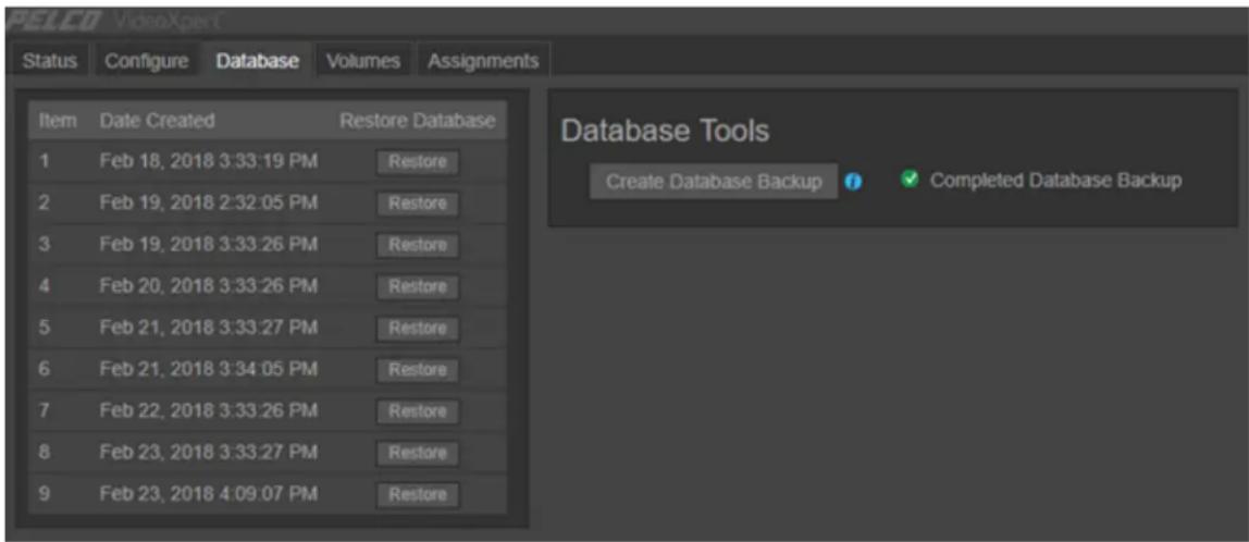
text_image
PELEO VideoXpert Status Configure Database Volumes Assignments Item Date Created Restore Database 1 Feb 18, 2018 3:33:19 PM Restore 2 Feb 19, 2018 2:32:05 PM Restore 3 Feb 19, 2018 3:33:26 PM Restore 4 Feb 20, 2018 3:33:26 PM Restore 5 Feb 21, 2018 3:33:27 PM Restore 6 Feb 21, 2018 3:34:05 PM Restore 7 Feb 22, 2018 3:33:26 PM Restore 8 Feb 23, 2018 3:33:27 PM Restore 9 Feb 23, 2018 4:09:07 PM Restore Database Tools Create Database Backup ✓ Completed Database BackupManually Backing Up the Database on VideoXpert Professional™ Systems
- Launch VideoXpert Storage Portal.
a. Login to VxPortal.
b. Click admin in the upper-right of the window to access the pull-down menu.
c. Click Configure Server.
d. Enter the Username and Password, and then click Log In. The default Username and Password are both "admin".
-
Click the Database tab.
-
In the Database Tools area, click Create Database Backup.
- In the Backup Database confirmation dialog box, click Backup.
When the backup is complete, Completed Database Backup will be displayed in the Database Tools area of the window.
Restoring the Database on VideoXpert Professional™ Systems
Restoring the database restores camera associations (provided the camera still exists within the VideoXpert environment) and storage settings. Restoring the database will not affect video directly; you will not lose video when restoring to an earlier time. However, if you have added cameras to the recorder after a backup was taken, and restore to that backup, you will lose access to video for any cameras the database restore process removes from the database.

Note: The NTP server address is not recovered during backup or restore. The NTP address must be reset manually after the backup or restore is complete.
- Launch VideoXpert Storage Portal.
a. Login to VxPortal.
b. Click admin in the upper-right of the window to access the pull-down menu.
c. Click Configure Server.
d. Enter the Username and Password, and then click Log In. The default Username and Password are both "admin".
- Click the Database tab.
- In the table, locate the backup to be restored, and then click the corresponding Restore button.
- In the Backup from [identifier] confirmation dialog box, click Restore.

Note: Restoring can take several minutes, and there is no way to cancel a restoration that is in progress.
- After you are automatically logged out, log back in.
When the restore operation is complete, Completed Restore for Backup [#] is displayed in the Database Tools area of the window.
Configuring the SMTP Server
You can configure the SMTP server to send email from the host to an email address. To do so:
- In VxToolbox, click System, and then click SMTP.
- If the Mail From field is not already populated with the correct value, enter a valid email address in the field.
- Enter a value in the SMTP Host field.
- Enter a number in the SMTP Port field.
- (Optional) Click to select the checkbox for Enable SMTPS.
- (Optional) Click to select the checkbox for Enforce validation of the server's certificate.
- Enter a value in the Username field.
-
Enter a value in the Password field.
-
Click Send Test Email, enter an email address in the Send Test Email dialog box, in the Send to Email field, and then click Send Email.
-
If the Send Test Email dialog box returns "Test email sent successfully!", click OK.
-
If the Send Test Email dialog box returns "Test email failed...", click Try Again, either correct the email address, and then click Send Email; or click Cancel, correct any errors in the SMTP configuration, and then try to send a test email again.
-
(Optional) To cancel the changes and return to the previously saved settings, click Revert.
-
Click Save Settings.
Controlling Memory Usage
VxToolbox memory usage defaults to 1 GB. To expand the amount of memory available to 4 GB:
- Create a file titled "user_runtime.txt".
- In the file, type "-Xms4g".
- Save the file to C:\ProgramData\Pelco\VxToolbox.
- Restart the VxToolbox service so that the change will take effect.
Configuring Monitor Walls
You can use existing monitors to configure several monitor walls.
Creating a Monitor Wall
- Click the Monitor Walls tab.
- At the bottom of the left panel, click the Add a new Monitor Wall icon (+).
- In the Add a Monitor Wall field at the upper left corner of the monitor wall window, enter a name for the monitor wall.
- In the Drag Monitors to assign (right) panel, click and drag a monitor to the location you would like it to appear on the monitor wall. Repeat this step for each monitor that you want to add
- To refresh the list of monitors, in the upper right corner of the Drag Monitors to assign (right) panel, click the Refresh icon ( ).
- To filter the list of monitors, in the Drag Monitors to assign (right) panel, enter a value in the Search Monitors field.
- (Optional) To delete a monitor from the monitor wall, in the left panel, click the Delete icon (☐) in the monitor to delete.
- (Optional) Scale the monitors:
• To resize the monitors individually, click on a monitor and drag a corner to resize it.
- To zoom in and out on all monitors by the same percentage, in the preview window, drag the selector bar to the appropriate magnification level. The images below show the monitor wall preview at 100% magnification and at 300% magnification. Notice that the monitors are no longer included in the frame.
text_image
100% ×100% Magnification
text_image
300%300% Magnification
- (Optional) If necessary, move the monitors into the monitor wall frame:
- Use the scroll bars at the bottom and right edges of the monitor wall window to bring the monitors into view.
- In the preview window, drag the monitor wall frame so that the appropriate monitors are in the frame. The image below shows the monitors at 300% magnification, but they are now included in the monitor wall frame.
text_image
300% ×- (Optional) Rearrange the monitors in any configuration by dragging them to the desired locations on the monitor wall. The image below shows the monitor wall with overlapping monitors and without overlapping monitors.
text_image
250% ×With Overlapping Monitors
text_image
250%Without Overlapping Monitors
- When you are satisfied with the look of the monitor wall, click Save.
Editing a Monitor Wall
- Click the Monitor Walls tab.
- In the left panel, click to select the monitor wall to edit.
- At the bottom of the left panel, click the Edit the selected Monitor Wall icon ( ).
- Update the monitor wall as needed, using the steps in the section titled Creating a Monitor Wall.
- When you are satisfied with the look of the monitor wall, click Save.
Deleting a Monitor Wall
- Click the Monitor Walls tab.
-
In the left panel, click to select the monitor wall to delete.
-
At the bottom of the left panel, click the Delete the selected Monitor Wall icon (☐).
-
In the confirmation dialog box, click Delete.
Using Send Video Permissions
The Send Video permission enables a user to send video to a remote monitor wall based on the user's role and permissions.

Note: You can only send video to a monitor that has a number assigned to it. See the Configuring Monitors section of this manual.
Using the instructions in the section titled Creating a Role, in the In the Edit Role window:
- If Surveillance is not in the Enabled Permission area, click Add a Permissions Category, and then click Surveillance.
- Click to expand Surveillance.
- Click to select the checkbox for Allow Select Surveillance Permissions.
- If the Send Video permission is not listed, click Add a Permission, and then click Send Video.
- If necessary, in the Allow Resources column of the Send Video permission row, click the Select Resource icon().
-
In the Manage Resource Restriction for window, use the drop-down menu to click one of the following:
-
Allow All Resources
- Allow Selected Resources
-
Allow All Resource Except Selected
-
If you chose Allow Selected Resources or Allow All Resources Except Selected, in the list of resources in the right panel, click to select and deselect the checkboxes for the appropriate resource names.
- Click OK.
- Continue using the instructions for creating a role.
Using Reports
From the Reports page, you can create and generate reports, and export them from the system. Reports are exported in CSV format.
Report Templates preloaded to VxToolbox include:
- Default Camera Report
- Default Device Report
- Default Event Report
• Default Recording Gap Report - Default Role Report
- Default Camera Role Access Report
- Default Storage Report
- Default User Report
- Default User Action Report
- Default System Status Report
You can edit an existing report template, or create a new one and edit the template details to include only the information needed.
Generating reports containing a large number of events might take some time. You can navigate away from the Reports page while the system generates your report. If your report parameters are too large, the request might time-out and the system might ask you to narrow your search.
Creating a Report Template
You can generate reports either manually or automatically from any of the templates in the Report Templates panel. To create a new template.
- Click the Reports tab.
- In the Report Templates list in the left panel, create a new report template using one of the following methods:
- To make a copy of an existing template from the Report Templates panel, select the template in the Report Templates panel, and then click the Create a copy of the selected Report Template icon (☐). A new template (named the same as the original template - Copy) is added to the list.
- To make a copy of an existing template from the Template Details for [template name] panel, select the template, and then click the Save as New Template button at the lower left of the Template Details for [template name] window (upper left panel). In the Save New Template dialog box, enter a value in the Template Name field, and then click Save.
-
To start with a blank template, click the Create a new Report Template icon (+). A New Unsaved Template is added to the list.
-
Click to select the new report template.
-
If the Report Type drop-down menu is available, select from the report type.
The report type can only be selected if you started with a blank template; if you copied an existing template, the copy is assigned the same report type as the original.
- If the Include [report type] (rows) field is displayed:
a. Click to select All or Selected from the drop-down menu.
b. If you clicked Selected, click the Select report filter sources icon (☑) under the drop-down menu; in the Select [report type] window, click to select and deselect the appropriate options, and then click OK.
- In the Include Info (columns) field, click to select and deselect the checkboxes for information to include in the report template.
As you select and deselect this information, you can preview the report in the Column Preview for [report template name] panel in the (vertical) center of the window.
- If the Time Range field is displayed, select an option from the drop-down menu. If you select Custom, set start and end dates and times in the Date & Time fields, either by typing-in values (mm/dd/yy and hh:mm AM or PM formats) or by using the selectors available by clicking the date icon 📄 or the time icd().
- (Optional) To generate a report for this template automatically:
a. Click to select the checkbox for Automatically Generate this Report.
b. From the drop-down menu below the option, select the day of the week on which the report will be generated.
c. Type or click to select a time in the at field.
d. (Optional) Click to select the checkbox for Automatically Export to .csv. If you select this, enter a Network Storage Location, Username, and Password. The user name and password are optional.
-
Depending on how you created the template and what you want to do, click Save, Save template changes, or Save as new template.
-
If the Save New Template dialog box is displayed, type a new name in the Template Name field, and then click Save.
Editing a Report Template
If appropriate, you can edit an existing template.
- Click the Reports tab.
- In the Report Templates list in the left panel, click to select the template to edit.
-
In the Template Details for [template name] (right) panel, make any changes needed to the template, except for the Report Type. The Report Type cannot be edited.
-
To save this over the existing template, click Save template changes.
If you do not want to overwrite the existing template, you can click Revert to cancel the changes, or click Save as new template to save the settings as a new template.
Deleting a Report Template
If appropriate, delete a template.
- Click the Reports tab.
- In the Report Templates list in the left panel, click to select the template to delete.
- Click the Delete Template con ().
- In the confirmation dialog box, click OK.
Generating a Report Manually
Even if a report is generated automatically, you can generate the report manually, as needed.

Note: You can run camera and device reports for locally discovered devices (VX System is None).
- Click the Reports tab.
- In the Report Templates list in the left panel, click to select the report to generate.
- In the Column Preview for [report template name] panel (vertical center of the window), at the right of the panel:
a. Type a value in the Name your report field, or keep the default report name.
b. Click Generate Report.
The report is listed in the Generated Reports table at the bottom of the window.
Exporting a Generated Report
To export a report from the Generated Reports table:
- Click the Reports tab.
- In the Generated Reports table at the bottom of the window, click to select the report to export.
- Click Export to .csv.
- Browse to a file location and, if appropriate, type a new value in the File name field.
- Click Save.
Deleting a Generated Report
To delete a report from the Generated Reports table:
- Click the Reports tab.
- In the Generated Reports table at the bottom of the window, click to select the report to delete.
- Click the Remove report file icon ().
- In the confirmation dialog box, click OK.
Managing Events
From the Events tab, you can configure event details and notifications to ensure that the right users are notified when the system records a particular action or alarm.
Finding and Filtering Events
Use filtering options to show the events relevant to you. Filters appear in the left-most panel of the Events tab and in some other tabs.
- Click the Events tab.
-
Click the expand the Filter panel, and then do one or more of the following.
-
Enter values in the Situation Filter field to filter by name, ID, model, IP address, serial number, vendor, or software version.
- Select an event Category from the pull-down menu
- Select an option from the Requires Acknowledgment pull-down menu.
- Select an option from the Pop-Up Banner pull-down menu.
- Select an option from the Audio Alert pull-down menu.
- Enter a range in the Severity fields, either by typing-in a number or selecting one using the up and down arrows
- Select the Users from the pull-down menu.
- Select the event Roles from the pull-down menu.
- Click the Clear the current filter settings icon (✗) to clear the filters.
The events matching the filter criteria are listed in the main panel.
Viewing and Configuring Event Details
- Click the Events tab.
- In the center panel, click to select the event you want to view or modify. You can use the filter, as described in the section titled Finding and Filtering Events.
- Event details are shown in the right column. If necessary, click to expand Event Details.
- To edit the event details settings, access the Event Details for dialog box by one of these methods:
- In the right panel, click the edit icon (√) to the right of Event Details.
- Right-click the event name, and then click Edit Event Details.
-
In the Event Details for dialog box, change event settings as necessary.
-
Click to select or deselect the checkbox for Enable logging and notification to determine whether VideoXpert will report the event. If you select Enable logging and notification, VideoXpert will report the event.
- Click to select or deselect the Use Custom Display Name.
- If you selected Use Custom Display Name, enter a name in the corresponding field. The Custom Display Name is how VideoXpert will represent the event.
-
(Optional) If you selected Enable logging and notification, change the Severity, if necessary, either by moving the slider bar or typing a number in the field. The severity might help users determine whether or not they need to act on an event.
-
Click Save.
Viewing and Configuring Event Notifications
- Click the Events tab.
- In the center panel, click to select the event you want to view or modify. You can use the filter, as described in the section titled Finding and Filtering Events.
- Event notification settings are shown in the right column. If necessary, click to expand Notification Settings, and view the notification information.
- To edit the event notification settings, access the Notification Settings dialog box by one of these methods:
- In the right panel, click the edit icon (✗) to the right of Notification Settings.
- Right-click the event name, and then click Edit Notification Settings.
- Click to select the checkbox for the appropriate Notification Behavior.

Note: You can select more than Notification BehaviorIf you do, all settings in the Notification Detailsection of the dialog box will be configurable as described below.
- If you selected Generate a Pop-Up Banner, configure these notification settings:
a. In the Roles and Users to Notify section of the dialog box, and then:
- Click in the Roles field, and then click to select one or more roles.
- Click in the Users field, and then click to select one or more users.
b. Scroll to the Notification Details section of the dialog box.
c. Click to select or deselect the checkbox for Auto-Acknowledge After. If you select this option, also set a time interval, either by typing-in a number or selecting one using the up and down arrows in the first field, and then selecting the units (for example: Minutes) from the drop-down menu.
- If you selected Require Acknowledgment, configure these notification settings:
a. In the Roles and Users to Notify section of the dialog box, and then:
- Click in the Roles field, and then click to select one or more roles.
- Click in the Users field, and then click to select one or more users.
b. Scroll to the Notification Details section of the dialog box.
c. Click to select or deselect the checkbox for Do Not Hide Cell Alerts. Events associated with individual video sources provide alerts within VxOpsCenter cells; these alerts hide after three seconds. Select this option to prevent the alert from hiding.
d. Click to select or deselect the checkbox for Auto-Acknowledge After. If you select this option, also set a time interval, either by typing-in a number or selecting one using the up and down arrows in the first field, and then selecting the units (for example: Minutes) from the drop-down menu.
e. (Optional) Click to select the checkbox for Allow Snooze (And Set Snooze Time), and then click the checkboxes to select and deselect the available intervals.
- If you selected Generate an Audio Alert, configure these notification settings:
a. In the Roles and Users to Notify section of the dialog box, and then:
- Click in the Roles field, and then click to select one or more roles.
- Click in the Users field, and then click to select one or more users.
b. Scroll to the Notification Details section of the dialog box.
c. Select the radio button for either Standard Chime or Custom Sound. If you select Custom Sound, browse to the Audio File, and then click Open.
d. Type or select a value for the Play Sound [#] times field.
e. Type or select a value in the Delay Sound Playback For [#] seconds between iterations field.
- (Optional) To create a custom event:
a. Click to select the checkbox for Generate a Custom Event.
b. Type a value in the Event Type Name field.
c. Set the Severity level, either by moving the slider bar or typing a number in the field.
d. Click to select or deselect the checkbox for Log this Event in the Event Log.
-
When you have finished configuring responses, click Save.
-
When you have finished configuring the rule, click Save.
Using Maps™
The Maps tab in VxToolbox is used to import and use AutoCAD 2013 DWG files and raster maps (jpeg or png), and to use ESRI Street) maps, allowing customers to use their pre-existing building maps with Maps in VideoXpert.
- In VxToolbox, ensure that your system is set up for Maps. You can then create a new map, view or edit an existing map, manage permissions for maps, and remove an existing map.
- In VxOpsCenter, the operator can launch Maps, select a map file, add cameras to a map, manage available maps, set user preferences for mapping, and view an existing map. Refer to the VideoXpert OpsCenter section of this manual.
Preparing Your System for Maps
Maps requires the following prerequisites to function properly:
- Ensure that Visual C++ Redistributable for Visual Studio 2015 is installed. It can be found at https://www.microsoft.com/en-us/download/details.aspx?id=48145. This is installed by the VxToolbox or VxOpsCenter installer. If this was not installed, reinstall VxToolbox or VxOpsCenter.
• Install VideoXpert v 3.5 or later, and the latest version of VxToolbox.
• AutoCAD files must use the 2013 format.
Creating a New Map
- If you have not already done so, start VxToolbox, and then click the Maps tab.
-
In the left panel, click the Add a Map icon (+), and then click to select one of the following:
-
For an outdoor map, select Add a World Map (ESRI Street Map).
• To use a jpeg or png file, select Add a Raster Map (jpeg or png). -
For an indoor map, select Add a DWG Map.
-
If you selected Add a World Map (ESRI Street Map):
a. Type a value in the Name field.
b. Click Save.
- If you selected Add a Raster Map (jpeg or png):
a. Type a value in the Name field.
b. Click Browse, navigate to and select the file, and then click Open.
c. Click Save.
- If you selected Add a DWG Map:
a. In the Add a DWG Map dialog box, type a value into the Name field.
b. Under Select a map file, click Browse, select all files (including all xref dwg files), and then click Open.
c. Click Save.
Viewing an Existing Map
- If you have not already done so, start VxToolbox, and then click the Maps tab.
Ensure that the user logging in is assigned the “administrator” role or has all of the maps permissions assigned.
- From the list of maps in the left panel, click the map to preview.
The selected map is displayed in the right panel.
Editing an Existing Map
-
If you have not already done so, start VxToolbox, and then click the Maps tab.
-
In the left panel) click to select the map to edit.
-
Click the Edit map n ().
-
(Optional) To change the name of the map, type a new value in the name field to the right of Edit Map.
-
(Optional) To add cameras to the map, click the Cameras tab in the left panel, and from there, drag the camera name to the appropriate location on the current map.
-
(Optional) To add a link from the current map to another map, click the Maps tab in the left panel, and from there, drag a map name to the appropriate location on the current map.
-
(Optional) To add doors, alarms, and other devices, click the Other tab in the left panel, and from there, drag an item to the appropriate location on the map.
-
(Optional) To move a camera, linked map, or other item on the map, click the item to be moved, and drag it to the appropriate location.
-
To rotate a camera, right-click it, and then select a value in the Set Rotation window, either by using the slider bar or by typing a value in the field. Click anywhere in the map to close the window.
-
To remove a camera, drawing, or device from the map, right click it, and then click Remove From Map.
-
At the lower right of VxToolbox, click Save.
Deleting an Existing Map
-
If you have not already done so, start VxToolbox, and then click the Maps tab.
-
In the left panel, click to select the map to delete.
-
At the lower right corner of the left panel, click the Delete map icon (☐).
-
In the confirmation dialog box, click Delete.
Managing Permissions for Maps
After you have created maps, use VxToolbox to assign map permissions to different roles.
-
If you have not already done so, start VxToolbox, and then click the Maps tab.
-
Refer to the section titled Managing Users and Roles for instructions to add, edit, and assign roles.
Using VideoXpert Portal and VideoXpert Storage Portal
Using VxPortal™
VxPortal™ is a Web interface that enables you and other users to view live and recorded video from your VxPro system without using VxOpsCenter client.
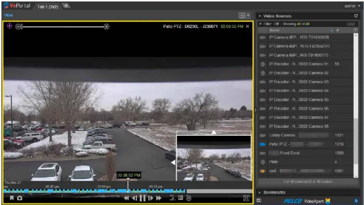
text_image
VxPortal Tab 1 (2x2) View Pato PTZ - D6230L - J230071 03:09:02 PM Thu Nov 21 02:45 pm 03:00 pm 03:15 pm 03.08.52 PM Video Sources Filter Off Showing 49 of 49 Color Name IP Camera-IRP_1ER-T91600828 IP Camera-IMP_1ER-T42304270 IP Camera-IMP_IRS-T91600773 IP Encoder - N_0032 Camera 01 55 IP Encoder - N_0032 Camera 02 IP Encoder - N_0032 Camera 03 IP Encoder - N_0032 Camera 04 IP Encoder - N_0032 Camera 05 IP Encoder - N_0032 Camera 06 IP Encoder - N_0032 Camera 07 IP Encoder - N_0032 Camera 08 Lobby Camera 1021 Patio PTZ - 1016 Front Desk 1000 Plate 4 roof 4001 1 of 49 selected (0 of 49 headers) Bookmarks PELCO VideoXpertVideoXpert Portal requires:
- Current version of Google Chrome, Mozilla Firefox, or Microsoft Edge
VxPortal operates as a simplified version of VxOpsCenter™.
• To view cameras:
- Double-click or drag a camera into the cell you want to view it in.
- Select multiple cameras and drag them to a tab to view each of the selected cameras in a separate cell. If you select more cameras than there are cells in the tab, another tab will open to display the additional cameras.
- Roll over a cell to engage playback controls.
• Hover over the timeline to see a thumbnail of recorded video corresponding to the time.
- Change layouts, use filters, create bookmarks, and perform other operations as you would in VxOpsCenter. See the VxOpsCenter section of this document. If you change the layout of the desktop, the layout is saved and will be loaded again the next time you access VxPortal.
Accessing VxPortal™
-
Launch VxPortal by one of the following methods:
-
Click the VxPortal icon on the desktop.
- Open a web browser and go to the IP address of VxPortal (for example: https://[ip address of VxPro]); if you are using Single Sign-ON (SSO), go to the domain name that you used during system configuration.

Caution: If you are using SSO, you must access VxPortal using the same domain name as was added in the configuration steps. If you do not, SSO will not be enabled.

Note: If the server(s) on which the VideoXpert system is installed are configured for FIPS mode, VxPortal might not work in Chrome and Firefox browsers. Use Microsoft® Edge.
- Enter your Username and Password, and then click Log In.
Configuring a Browser to Enable Single Sign-On in VxPortal™
Single Sign-On (SSO) allows users to log in to multiple systems using a single set of login credentials. SSO can be used with either Single-Stage or Two-Stage binding, and can be used with the Synchronize Users and Roles From LDAP authentication options.
SSO is selected and configured in VxToolbox™. To use SSO in VxPortal, if you are using Mozilla Firefox or Microsoft Edge as the browser, configure the browser as described in the sections below.

Caution: If you are using SSO, you must access VxPortal using the same domain name as was added in the configuration steps. If you do not, SSO will not be enabled.
Configuring Mozilla Firefox to Enable Single Sign-On in VxPortal™
If you are using Mozilla Firefox to access VxPortal, and you need to enable Single Sign-On (SSO), configure the browser as follows:
- Launch Firefox.
- Type about: config into the Search or Enter Address field, and then press Enter or click the right-arrow at the right of the field.
- If a warning appears, click I accept the risk!.
- In the window that lists preference information, type "negotiate" in the search field.
- Double-click network.negotiate-auth.trusted-uris.
- In the Enter string value dialog box, enter the Fully Qualified Domain Name (for example: "my-VxPro-system.com"), and then click OK.
- Close the browser or navigate to another page.
Configuring Microsoft Edge to Enable Single Sign-On in VxPortal™
If you are using Microsoft Edge to access VxPortal, and you need to enable Single Sign-On (SSO), configure the browser as follows:
- In the Windows Explorer search field, type "Internet Options", and then click to open Internet Options.
-
In the Internet Properties window, click the Security tab, click Local Intranet, and then click Custom level.
-
Under User Authentication, click to select the radio button for Automatic logon only in Intranet zone, and then click OK.
- Click Sites.
- In the Local intranet dialog box, click to deselect the checkbox for Automatically detect intranet network, click to select the remaining checkboxes, and then click Advanced.
- In the next Local intranet dialog box, in the Add this website to the zone field, enter the Fully Qualified Domain Name (for example: "my-VxPro-system.com"), and then click Add.
- Verify that the Fully Qualified Domain Name is listed in the Websites field, and then click Close.
- Click OK.
- Click Apply, and then click OK.
Changing the System Password in VxPortal™
For security purposes, you should change the default password for your system. To change it using VxPortal:
- Click admin in the upper-right of the window to access the pull-down menu.
- Click Change Password.
- In the Change Password dialog box, enter the requested information in the fields, and then click Change Password.
Viewing Video Sources and Bookmarks in VxPortal™
VxPortal behaves much like VxOpsCenter in that you can:
- Create and configure tabs.
- Open video sources in cells and interact with them.
- Create, edit, and delete bookmarks, and open them in cells.
• View the Event Counter. - Move Mission Control to the right or left panel.
See the VxOpsCenter section of this manual.
When you are viewing a video source or bookmark in VxPortal, you can select a maximum video quality for all cells in the tab.
- At the upper left corner of the tab, above the cells, click View.
- Hover over Max Video Quality.
- Click to select the appropriate option from the drop-down menu.

Note: If you select highest Available Quality video quality matches the highest quality of the video source. For example: if your video source supports H264, that is the quality displayed by VxPortal.
- Click anywhere in VxPortal.
Managing Exports
- Click admin in the upper-right of the window to access the pull-down menu.
-
Click Manage Exports.
-
In the Export Archive window, view the list of exports in the table.
-
(Optional) Click on any column title (except Action), to sort by the values in that column.
-
(Optional) Click to expand Filter, and then do one of the following: enter a file name or creator; select From and To start and end dates and times; and/or select a Status to view a subset of all exports. Click Clear All to clear the filter fields.
-
(Optional) To download a record from the Export Archive, click Download in the Action column for the archive row, and then click Open.
- (Optional) To edit the export name, click the pencil icon (√) in the Action column for the archive row; in the Edit Export Name dialog box, type a value in the New Name field, and then click Save.
-
(Optional) To delete an export, click the trashcan icon (☐) in the Action column for the archive row; in the confirmation dialog box, click to select or deselect the checkbox to Delete Permanently, and then click Yes.
-
If you did not select Delete Permanently, the archive is removed from the current list, and is added to the Export Trash Bin.
-
If you did select Delete Permanently, the archive is deleted, but not added to the Export Trash Bin.
-
If you want to view deleted exports, click the down arrow to the right of Export Archive, and then select View Trash Bin.
-
To move an export from the Export Trash Bin to the Export Archive window, click the export Restore button.
- To delete one item in the Export Trash Bin, click the export Delete button. In the confirmation dialog box, the checkbox for Delete Permanently is already selected. Click Yes.
- To delete all items in the Export Trash Bin, click the down arrow to the right of Export Trash Bin, and then click Empty Trash Bin. In the confirmation dialog box, the checkbox for Delete Permanently is already selected. Click Yes.
-
To return to the Export Archive window, click the down arrow to the right of Export Trash Bin, and then click Close Trash Bin.
-
If you want to delete failed exports, click the down arrow to the right of Export Archive, and then click Delete All Failed Exports. In the confirmation dialog box, click to select or deselect the checkbox for Delete Permanently, and then click Yes.
-
To exit the window, click Xe in the upper-right corner of the window or click outside the window.
Configuring the Server
To configure the VideoXpert Server ^TM :
- Click admin in the upper-right of the window to access the pull-down menu.
- Click Configure Server.
This launches VideoXpert Storage Portal.
- Log in to the server, and see the section titled Configuring Advanced Storage Using VideoXpert Storage Portal™ of this manual for instructions on using the interface.
Viewing Keyboard Shortcuts
To view a list of keyboard shortcuts for VxPortal:
- Click admin in the upper-right of the window to access the pull-down menu.
- Click Keyboard Shortcuts.
- To exit the window, click the X in the upper-right corner of the window, or click outside the window.
Logging Out
To properly exit VxPortal:
- Click admin in the upper-right of the window to access the pull-down menu.
- Click Log Out.
Configuring Advanced Storage Using VideoXpert Storage Portal™
VideoXpert Storage Portal provides advanced settings and status that can help you fine-tune and monitor your VideoXpert Storage devices.
Accessing the VideoXpert Storage Portal™
- Login to VxPortal.
- Click admin in the upper-right of the window to access the pull-down menu.
- Click Configure Server.
- Enter the Username and Password, and then click Log In. The default Username and Password are both "admin".
- If you are prompted to do so, reset the password.
Checking VideoXpert Storage™ Status
The Status page provides basic status information about your storage/recorder to help you determine whether you are under-utilizing or over-burdening the recorder.
- In VideoXpert Storage Portal, click the Status tab.
- View the available information.
Generating and Downloading Storage Logs
Storage logs can provide insight to an anomaly with the recorder or one of the sources recording to it. When requesting support from Pelco, a Pelco technician might request logs from the recorder. To generate and download Storage logs:
- In VideoXpert Storage Portal, click the Status tab.
- Click Generate Log Archive.
- In the Generate Logs dialog box, click Generate.
- When the log has been successfully generated, click Download Log Archive (to the left of the Generate Log Archive button).
- Save the zip file to an appropriate location.
Configuring the Server in VideoXpert Storage Portal™
Use the Configure page to assign an NTP address to the recorder. You should assign the recorder to the same NTP server as the rest of your VideoXpert network to ensure time is properly synchronized.
From this page, you can also change the transmission method and retention period for the recorder.
- In VideoXpert Storage Portal, click the Configure tab.
- Enter an appropriate number of days in the Maximum Retention Period field.
- In the Transmission Method field, click to select the radio button for Multicast or Unicast.
- Click Save.
Managing Database Backups
You can backup your storage database and restore the backups. You can also recover recording that were written to disk, even if the database was lost:
- In VideoXpert Storage Portal, click the Database tab.
- (Optional) To restore the database from an existing backup, in the Database Backups panel:
a. Identify the backup to restore, and then click Restore to the right of the backup.
b. Click Restore in the Backup from [backup name] dialog box.
The Recovering recordings massage is displayed to the right of the Recover Recordings button, and then the Recovery successful message is displayed. Depending on the amount of video being recovered, this process can take up to a few hours.
- (Optional) To create a new backup:
a. In the Database Tools panel, click Create Database Backup.
b. In the confirmation dialog box, click Backup.
When the backup has been created, the Completed Database Backup message is displayed to the right of the Create Database Backup button.
- (Optional) To recover video recordings:
a. In the Database Tools panel, click Recover Recordings.
b. In the Recover Recordings dialog box, select the Recover from Volume from the drop-down menu, specify a Date/Time Range to Recover in the Start and End fields, and then click Recover.
When the recovery is complete, the Recovery successful message is displayed. Depending on the amount of video being recovered, this process can take up to a few hours.
Using Volume Groups and Volumes
You can organize your device video storage by creating and managing Volumes and Volume Groups.
- A volume is a logical directory in which you want to store video.
- A volume group is a group of volumes to which cameras are assigned and distributed. You can use volume groups to:
- Separate types of storage (like internal vs. external)
- Set different retention parameters for different sets of drives.
- Write video to more than one volume. When all volumes are full, the system will overwrite volume containing the oldest stored video.
- The system ships with a volume group called Default Volume Group. You can rename or delete this volume group.
- An archive volume group is a volume group to which the recorder will move the oldest video from the other volume groups, instead of deleting the oldest video. See the section titled Using External NAS Storage (Archive Volume Group) for more information about the archive volume group.
Using External NAS Storage (Archive Volume Group)
By connecting an external volume (network storage/NAS), you can extend your retention time for VideoXpert Storage recorder. When your VideoXpert Storage recorder achieves its maximum capacity and would normally begin to delete the oldest video, it will send video to the NAS instead. Video will still adhere to retention parameters, even when moved to external storage. The experience in accessing video is the same, whether a recording is served from a the VideoXpert Storage recorder or an external server.

Note: VideoXpert supports SMB1 NAS servers when using anonymous access. For systems that require a username/password for NAS access, you must use SMB2 or higher.
The external storage server must reside on the VideoXpert network. You can select whether to require login credentials. If the server requires and is provided login credentials, NAS Authentication is enabled.
As video transfers from a VideoXpert Storage recorder to an external storage server, bandwidth of your incoming cameras is equal to the bandwidth out to external storage. When using external storage, you should plan storage distribution to ensure bandwidth availability for incoming cameras, storage overflow, and user impact in viewing recorded video.

Note: While each VideoXpert Storage recorder can only have a single archive group, multiple VideoXpert Storage recorder can use the same NAS server. In this case, each VideoXpert Storage recorder must point to a different path/folder on the NAS server; pointing multiple VideoXpert Storage recorder to the same archive group network path will cause video to expire earlier than expected and without warning. You can individually select whether each path uses NAS Authentication.
Creating a New Volume Group
- In VideoXpert Storage Portal, click the Volumes tab.
-
At the bottom right of the Volume Groups panel, click the plus sign icon (+).
-
In the Create New Volume Group dialog box:
a. Enter a value in the Name field.
b. Click to select or deselect the checkbox for Designate this Volume Group as the Archive Volume Group.
c. Click OK.
- If you selected this volume group to be the archive volume group, and there is already a designated archive volume group, the Attention dialog box will inform you of this, and instruct you to remove the current archive volume group. To proceed:
a. Click OK
b. Identify the current archive volume group by the Archive Volume Group icon (💡) to the left of the volume group name.
c. Select the volume group that is the current archive volume group, click the pencil icon ( ), deselect the checkbox, and then click Save.
d. Add the new volume group, and select the checkbox to set it as the Archive Volume Group.
e. Click Save.
Editing a Volume Group
- In VideoXpert Storage Portal, click the Volumes tab.
- Click to select the volume group to edit.
- At the bottom right of the Volume Groups panel, click the pencil icon (☐).
- In the Edit Volume Group dialog box:
a. (Optional) Enter a value in the Name field.
b. (Optional) Click to select or deselect the checkbox for Designate this Volume Group as the Archive Volume Group.
c. Click Save.
- If you selected this volume group to be the archive volume group, and there is already a designated archive volume group, the Attention dialog box will inform you of this, and instruct you to remove the current archive volume group. To proceed:
a. Click OK
b. Identify the current archive volume group by the Archive Volume Group icon (💡) to the left of the volume group name.
c. Select the volume group that is the current archive volume group, click the pencil icon (), deselect the checkbox, and then click Save.
d. Add the new volume group, and select the checkbox to set it as the Archive Volume Group.
e. Click Save.
Deleting a Volume Group
- In VideoXpert Storage Portal, click the Volumes tab.
- Click to select the volume group to be deleted.
- At the bottom right of the Volume Groups panel, click the trashcan icon (☐). The trashcan icon turns red when you hover over it.
- In the Delete Volume Group dialog box, click OK.
- If you deleted the archive volume group, edit another volume group and select the checkbox to set it as the Archive Volume Group.
- If there is no designated archive volume group, the system will not archive video.
Creating a New Volume
- In VideoXpert Storage Portal, click the Volumes tab.
- In the Volume Groups panel, click to select a Volume Group to which the new Volume will be assigned.
- At the bottom right of the Volumes (center) panel, click the plus sign icon (+).
- In the Create New Volume Group dialog box:
a. Enter a value in the Path field.
b. Click to select or deselect the checkbox for Requires credentials. If you select this checkbox, enter values in the Username, Password, and Domain fields.
c. Enter a value in the Buffer Size field.
d. Click to select or deselect the checkbox for Reserve bandwidth for this volume.
e. Click OK.
Editing a Volume
- In VideoXpert Storage Portal, click the Volumes tab.
- In the Volumes (center) panel, click to select the volume to edit.
- At the bottom right of the Volumes panel, click the pencil icon (☐).
- In the Edit Volume Path dialog box:
a. (Optional) Type a new string in the Path field.
b. (Optional) Click to select or deselect the checkbox for Requires credentials. If you select this checkbox, enter values in the Username, Password, and Domain fields.
c. (Optional) Enter or select a value in the Buffer Size field.
d. Click to select or deselect the checkbox for Reserve bandwidth for this volume.
- Click Save.
Deleting a Volume
- In VideoXpert Storage Portal, click the Volumes tab.
- In the Volumes (center) panel, click to select the volume to be deleted.
- At the bottom right of the Volumes panel, click the trashcan icon (☐). The trashcan icon turns red when you hover over it.
- In the Delete Volume dialog box, click OK.
Associating Devices With a Volume
If you have more than one non-archive volume group, you can associated devices (cameras) with specific volume groups. This enables you to control data streams between the system and the volume groups.
- In VideoXpert Storage Portal, click the Volumes tab.
- In the Volume Groups (left) panel, click to select the volume group with which you will associate devices.
- In the Associated Devices (right) panel, click the pencil icon (√).
- In the Edit Devices in Volume Group "[group name]" dialog box:
a. Click to select or deselect the checkboxes for the devices to associate with the volume group, or click the checkbox to the left of Name to select or deselect all devices. Selected devices are shown immediately in the Associated Devices (left) panel.
b. Click the icon in the upper right corner of Edit Devices in Volume Group "[group name]" dialog box to close it.
- (Optional) Use the filter to show a subset of the devices in a volume group:
a. In the Volume Groups (left) panel, click to select the volume group.
b. In the Associated Devices (right) panel, in the Filter field, type in a value (for example "IP").
c. Click the x on at the right of the filter field to clear the filter.
Viewing Storage Assignments
You can check the status of individual streams and whether or not they are recording from the VideoXpert Storage Portal Assignments page.
- In VideoXpert Storage Portal, click the Assignments tab.
- In the Recorders (left) panel, click to select a recorder.
- Scroll through the device list to see the Name, ID, IP address, and Status of each device.
- Hover over a device name or ID to see the full text.
Selecting All Data on a Tab
- In VideoXpert Storage Portal, click to select the tab that contains information you want to copy.
- Right-click anywhere on the page.
- Click Select all.
- Open the application into which you will paste the information, and then paste the information.
- Click in VideoXpert Storage Portal to deselect the information.
Printing Data from a Tab
- In VideoXpert Storage Portal, click to select the tab that contains information you want to print.
- Right-click anywhere on the page.
- Click Print.
- Make the appropriate selections in the dialog box, and then click Print.
Reading Aloud
VideoXpert Storage Portal can read aloud the contents of any page, from a word of your choice to the end of the page.
- In VideoXpert Storage Portal, click to select the tab that contains information you want to hear.
- Right-click on a word or in a panel on the page from which you would like VideoXpert Storage Portal to start reading.
- Click Read aloud.
- The text is read from the page, and the corresponding text is highlighted.
- To read a specific word, double-click the word.
- Double-click anywhere in the page to end reading aloud.
Changing the Password
If a password expiration policy is in place (for example: your password expires every 90 days), you will see a warning dialog box when your password must be changed.

Note: Password expiration is not used with Single Sign-On (SSO). If your system is configured to use SSO, or if the expiration policy is set to Passwords never expire, then you will never see the warning dialog box.
- In the warning dialog box, click Change Password.
- In the Change Password dialog box, enter the current password and new password in the appropriate fields.
- Click Save.
You can also change your password at any time.
- In VideoXpert Storage Portal, in the upper right corner of the window, click Change Password.
- Enter the current password and new password in the appropriate fields.
- Click Change Password.
- In the Success dialog box, click OK.
- Login to VideoXpert Storage Portal using the new password.
Logging Out
To log out of VideoXpert Storage Portal, in the upper right corner of the window, click Logout.
Using VideoXpert OpsCenter
Configuring VxOpsCenter™
You must configure VxOpsCenter before use.
Running the Application for the First Time
When you run the application for the first time, you will create your user account, configure basic VxOpsCenter and video behaviors, and, most importantly, point VxOpsCenter to the VideoXpert System (s) ^™ you will use. Some steps in initial setup are optional; you only need to access these options if your workstation and network differ from default settings. The general work flow is as follows:
- If VxToolbox ^TM is open, close it.

Note: Do not run VxToolbox and VxOpsCenter at the same time. Doing so might cause memory-related issues.
- Run VxOpsCenter.

Note: If you are using single sign-on (SSO) and are accessing the VideoXpert system through a browser, use the Fully Qualified Domain Name (FQN) instead of the IP address.
- Create your Workstation Configuration account.
- This account is local to the workstation and preserves your configuration and your VideoXpert system credentials from other users who might access your workstation.
- Your workstation configuration account credentials may be the same as your VideoXpert user credentials, though you may want to use different credentials for your workstation configuration account to maximize security.
-
Configure your workstation, including your monitor layout. See the section titled Setting Up Your VideoXpert Workstation™.
-
Configure System Server Connections. See the section titled Configuring VX System™ Connections.
-
Indicate whether or not to allow multi-system access. See the section titled Enabling or Disabling Multi-System Access™ (Simultaneous Server Connections).
-
Login to VideoXpert with your standard credentials (not the Workstation Configuration credentials) to begin using VideoXpert.
Setting Up Your VideoXpert Workstation™
VideoXpert Workstation™ settings determine the basic behavior of the system. These instructions apply to the initial configuration only. You can re-configure the workstation at any time using the instructions in the section titled Reconfiguring Your VideoXpert Workstation™.
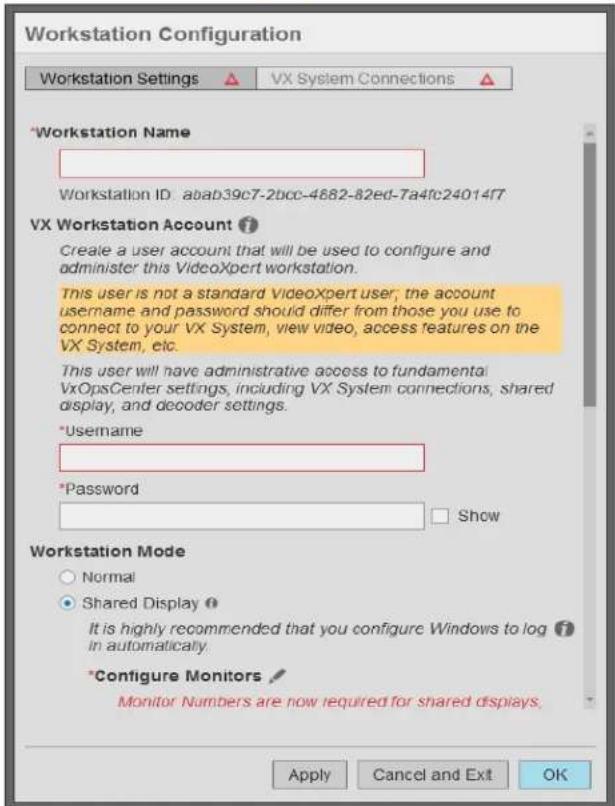
text_image
Workstation Configuration Workstation Settings ▲ VX System Connections ▲ *Workstation Name Workstation ID: abab39c7-2bcc-4882-82ed-7a4fc24014f7 VX Workstation Account ? Create a user account that will be used to configure and administer this VideoXpert workstation. This user is not a standard VideoXpert user; the account username and password should differ from those you use to connect to your VX System, view video, access features on the VX System, etc. This user will have administrative access to fundamental VxOpsCenter settings, including VX System connections, shared display, and decoder settings. *Username *Password □ Show Workstation Mode ○ Normal ● Shared Display ? It is highly recommended that you configure Windows to log in automatically. *Configure Monitors ? Monitor Numbers are now required for shared displays. Apply Cancel and Exit OK
Note: This screen will look different after initial configuration. If you do not see the red triangles on the Workstation Settings and VX System Connections buttons, see the instructions in the section titled Reconfiguring Your VideoXpert Workstation™.
- Enter a Workstation Name. This is the name by which VideoXpert Core™ will recognize the workstation and the name by which other users will recognize the workstation when sending video, responding to workstation-related events, etc.
- Enter values in the Username and Password fields under Vx Workstation Account.
- Under, Workstation Mode, select Normal or Shared Display mode. Shared Display mode provides monitor-wall functionality for one or more monitors. See the section titled Configuring Shared Display™ Mode for more information about Shared Display mode.
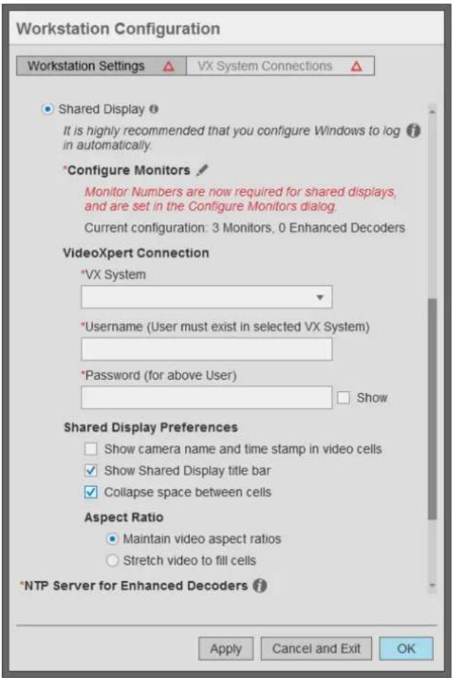
text_image
Workstation Configuration Workstation Settings ▲ VX System Connections ▲ Shared Display ? It is highly recommended that you configure Windows to log in automatically. *Configure Monitors # Monitor Numbers are now required for shared displays, and are set in the Configure Monitors dialog. Current configuration: 3 Monitors, 0 Enhanced Decoders VideoXpert Connection *VX System *Username (User must exist in selected VX System) *Password (for above User) □ Show Shared Display Preferences □ Show camera name and time stamp in video cells ✓ Show Shared Display title bar ✓ Collapse space between cells Aspect Ratio ● Maintain video aspect ratios ○ Stretch video to fill cells *NTP Server for Enhanced Decoders ? Apply Cancel and Exit OK- If you are going to control a monitor remotely, assign a number to the monitor. To do so:
a. Click the Configure Monitors icon (√) to the right of Configure Monitors to open the Configure Monitors window for the workstation.
b. Follow the instructions for assigning a number to each monitor to control. For example: assign a number to any monitor that will be included on a shared display.
- (Optional) click the checkbox to select or deselect Enable hardware acceleration. Hardware acceleration is enabled by default and should only be disabled if your workstation uses an unsupported graphics chipset, or if you need to troubleshoot graphics issues that may result from your graphics drivers and chipset.

Note: Hardware acceleration of H.265 is supported on the Shared Displays™ VX-A3-SDD and newer, and Enhanced Decoders VX-A3-DEC and newer.
-
Click Apply to save your workstation configuration settings.
-
Click VX System Connections and follow the instructions in the section titled Configuring VX System™ Connections.
Reconfiguring Your VideoXpert Workstation™
Workstation settings determine the basic behavior of the system. These instructions help you reconfigure the system. If this is the initial setup, see Setting Up Your VideoXpert Workstation™.
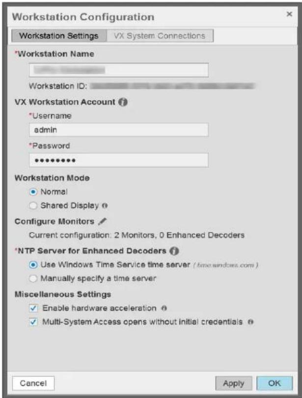
text_image
Workstation Configuration Workstation Settings VX System Connections *Workstation Name Workstation ID: VX Workstation Account ? *Username admin *Password ***** Workstation Mode Normal Shared Display Configure Monitors Current configuration: 2 Monitors, 0 Enhanced Decoders *NTP Server for Enhanced Decoders ? Use Windows Time Service time server ( time.windows.com ) Manually specify a time server Miscellaneous Settings Enable hardware acceleration Multi-System Access opens without Initial credentials Cancel Apply OK- In the VxOpsCenter Login window, from the Connect to System drop-down menu, select None - Configure Workstation; enter values in the Username and Password fields; and then click Log In.
- Launch the Workstation Configuration dialog box: In Mission Control, click the User Menu icon (▼), and then select Configure Workstation.
- (Optional) Enter a new string in the Workstation Name field. This is the name by which VideoXpert Core will recognize the workstation and the name by which other users will recognize the workstation when sending video, responding to workstation-related events, etc.
- (Optional) Enter new values in the Username and Password fields under Vx Workstation Account.
- (Optional) Under Workstation Mode, select Normal or Shared Display mode. Shared Display mode provides monitor-wall functionality for one or more monitors. See the section titled Configuring Shared Display™ Mode for more information about Shared Display mode.
- (Optional) click the checkbox to select or deselect Enable hardware acceleration. Hardware acceleration is enabled by default and should only be disabled if your workstation uses an unsupported graphics chipset, or if you need to troubleshoot graphics issues that may result from your graphics drivers and chipset.

Note: Hardware acceleration of H.265 is supported on the Shared Displays VX-A3-SDD and newer, and Enhanced Decoders VX-A3-DEC and newer.
- (Optional) Click the checkbox to select or deselect Multi-System Access opens without initial credentials (MSA). In MSA mode, VxOpsCenter will open with no VX Systems connected. Credentials will be required when you connect to a VX system.
- Click Apply.
- To change the VX System Connections, click VX System Connections, and then see the section titled Configuring VX System™ Connections.
- When you are done with the reconfiguration, click OK.
Configuring VX System™ Connections
The list of VX System Connections determines the VideoXpert environments to which your VxOpsCenter can connect. When users log in with their VideoXpert system credentials, VxOpsCenter will connect them to relevant VideoXpert environments. If a server is not in the list of system server connections, users will not be able to connect to it using VxOpsCenter.
Only the Workstation Configuration account can define system server connections. When you add systems using the Workstation Configuration account, and you are working in MSA mode, you can elect to provide credentials. If you add credentials for systems, then your Workstation Configuration account will also immediately connect you with your systems. If you do not provide credentials, then you must manually enter credentials for each system after you log in as the workstation configuration user. If you are using Single Server Access mode (non-MSA mode), you must always provide the credentials when logging in.
When setting up a connection to a server, you can determine streaming performance to the system. By default, system connections use the best possible streaming options, but you may need to disable settings or adjust your connection speed to account for the network between the workstation and the system to which you will connect. See the section titled Understanding System Streaming Performance Settings.
Working With Systems

Note: The Systems section is only present in Mission Control when you are using multi-system access (MSA) mode.
The Systems section of Mission Control shows the list of systems you are authorized to access.
- In Mission Control, click to expand Systems.
The Systems panel lists the systems that are available and whether sources, maps, and plugins from the systems are being included in the Content list (selected or deselected checkbox). It also enables you to filter the systems, view the systems list in a standalone window, and edit the systems.
- To use the System List Filter:
a. Click Filter to expand the filter panel.
b. Type a value in the Filter by field.
c. To clear the filter, do one of the following:
- Click the clear filter icon ( ) at the right of the Filter by field.
-
Click Clear at the upper right of the Systems panel.
-
To see more details about each system, click the Open as standalone window icon (☐) to the right of Systems.
Settings in the standalone window are reflected in the System panel.
- To change the systems for which you are showing content (sources, maps, and plugins) in the Systems panel or standalone window:
a. In the System list, click to select and deselect the checkbox for each system.
b. If the Enter User Credentials for the System dialog box opens, enter values in the Username and Password fields for the appropriate system, and then click OK.
c. If you see a Time Synchronization Error, acknowledge it by clicking OK.
- To change the columns displayed in the System List:
a. In the standalone window, if necessary, click to expand Show Columns in the left panel.
b. Click to select and deselect the checkboxes for the columns to include and exclude.
-
In the standalone window, click the up or down arrow in the column heading to sort the systems by in ascending or descending order.
-
To edit the system list:
a. Click the Edit icon() at the lower right of the Systems panel or standalone window.
b. In the Authenticate for Administrative Access dialog box, enter values in the Username and Password fields for the appropriate system, and then click Authenticate.
- To add a system:
a. Click the Add System Connection icon (+) at the lower right of the window.
b. Use the Configure System Connection window as described in Adding Servers to VxOpsCenter™
c. Click Save.
- In the standalone window, to export a System List.
a. Click the menu icon() at the lower left of the standalone window.
b. Click Export System List.
c. In the Export System List dialog box, enter a value in the System List File Name field.
d. In the To Location field, click Browse, and then browse to the location to which the file will be saved.
e. Click Save.
- In the standalone window, to import a System List:
a. Click the menu icon( ) at the lower left of the standalone window.
b. Click Import System List.
c. Click Browse, and then select the appropriate file.
d. Review the information in the Import System List window, and do one of the following:
- Click to select the radio button for Replace List.
-
Click to select the radio button for Merge Lists, and then click to select the checkboxes for each system that you want to replace with the imported information.
e. Click Import. -
To delete a system from the System List:
a. Click to select the system to delete.
b. Click the trash bin icon ( ) at the lower right corner of the window.
c. In the confirmation dialog box, click OK.
- To close the standalone window, click the close window × con ( ) at the upper left corner of the window.
Enabling or Disabling Multi-System Access™ (Simultaneous Server Connections)
Multi-system access (MSA) ^™ allows you to access multiple VideoXpert systems simultaneously using your VideoXpert system credentials. This can be enabled when you log in; however, you can also enable it during system configuration.

Note: The multi-system access option is available if you have more than one server connection added to VxOpsCenter.
To enable multi-system access:
- If you have not already done so, access the Configure Workstation window:
a. Log into VxOpsCenter with the Workstation Configuration account.
b. In Mission Control, click the User Menu icon (▼), and then select Configure Workstation.
- In the Workstation Configuration window, click VX System Connections.
- (Optional) To use a shared system list:
a. Click to select the checkbox for Use and manage a shared Systems List.
b. Click Browse, browse to a file to enter in the System List Location field, and then click Open.
c. If required, enter values in the Username and Password fields.
d. Click Load Systems.
- To add a server (if you are not using a shared system list):
a. Click the Add System Connection icon (+) at the lower right of the Workstation Configuration window.
b. (Optional) Enter information about the server in the Notes field. The notes are only available to the Workstation Configuration account.
c. Provide the IP of the server, or the FQN of the server if you are using single sign-on (SSO), in the Server Address field, and adjust the HTTPS Port value if different from the default.
d. (Optional) Adjust System Streaming Performance settings. See the section titled Understanding System Streaming Performance Settings.
e. (Optional) Click to select or deselect the checkbox for Validate SSL/TLS Certificate...
f. (Optional) If there are custom fields, enter a value in each field.
g. (Optional) To add custom fields (columns) to the System List by which you can sort, in the Configure System Connections window, below Custom Fields, click Add Another Custom Field (Column), enter a value in the Enter a new header name field (for example: City), enter an appropriate value for the system (for example: Denver) in the field below the new header name, and then click Save. The column and the value are shown in the System List.
h. (Optional) Type values in the Username and Password fields.
i. Click Test Connection to verify that you have provided the correct server address; testing the connection will require you to provide credentials to the server.
j. Click Save.
5. Click OK.
When multi-system access is enabled, the Systems section is available within VxOpsCenter. You can select or deselect systems to show or hide sources belonging to your various systems.
Adding Servers to VxOpsCenter™
- If you have not already done so, access the Configure Workstation window:
a. Log into VxOpsCenter with the Workstation Configuration account.
b. In Mission Control, click the User Menu icon (▼), and then select Configure Workstation.
-
In the Workstation Configuration window, click VX System Connections.
-
To import an existing system list:
a. Click to select the checkbox for Use and manage a shared Systems List.
b. Click Browse, browse to a file to enter in the System List Location field, and then click Open.
c. If required, enter values in the Username and Password fields.
d. Click Load Systems.
- To export the current system list:
a. At the lower left of the Workstation Configuration window, do one of the following, depending on which icon is present:
- If you are not using a shared system list, click the menu icon ( ), and then click Export System List.
- If you are using a shared system list, click the export system list icon ( ).
b. In the Export System List dialog box, enter a value in the System List File Name field, click Browse, browse to the location to which you will save the file, click OK, and then click Save.
- To add a server (if you are not using a shared system list):
a. Click the Add System Connection icon (+) at the lower right of the Workstation Configuration window.
b. (Optional) Enter information about the server in the Notes field. The notes are only available to the Workstation Configuration account.
c. Provide the IP of the server, or the FQN of the server if you are using single sign-on (SSO), in the Server Address field, and adjust the HTTPS Port value if different from the default.
d. (Optional) Adjust System Streaming Performance settings. See the section titled Understanding System Streaming Performance Settings.
e. (Optional) Click to select or deselect the checkbox for Validate SSL/TLS Certificate...
f. (Optional) If there are custom fields, enter a value in each field.
g. (Optional) To add custom fields (columns) to the System List by which you can sort, in the Configure System Connections window, below Custom Fields, click Add Another
Custom Field (Column), enter a value in the Enter a new header name field (for example: City), enter an appropriate value for the system (for example: Denver) in the field below the new header name, and then click Save. The column and the value are shown in the System List.
h. (Optional) Type values in the Username and Password fields.
i. Click Test Connection to verify that you have provided the correct server address; testing the connection will require you to provide credentials to the server.
j. Click Save.
-
When you have added all appropriate connections, click OK.
-
If the Log Out Required dialog box opens, click OK. You will be logged out. The configuration changes are applied when you log back in.
Editing a System Connection
- If you have not already done so, access the Configure Workstation window:
a. Log into VxOpsCenter with the Workstation Configuration account.
b. In Mission Control, click the User Menu icon (▼), and then select Configure Workstation.
-
In the Workstation Configuration window, click VX System Connections.
-
Click to select the system connection to be edited.
-
Click the Edit System Connection icon (✗) at the lower right of the Workstation Configuration dialog box.
-
In the Configure System Connection dialog box, make all necessary updates, and then click Save.
-
In the Workstation Configuration dialog box, click OK to save the settings.
-
If the Log Out Required dialog box opens, click OK. You will be logged out. The configuration changes are applied when you log back in.
Deleting a System Connection
- If you have not already done so, access the Configure Workstation window:
a. Log into VxOpsCenter with the Workstation Configuration account.
b. In Mission Control, click the User Menu icon (▼), and then select Configure Workstation.
-
In the Workstation Configuration window, click VX System Connections.
-
Click to select the system connection to be deleted.
-
Click the Delete System Connection icon (☐) at the lower right of the window to delete the connection to the server.
-
In the Delete System Server Connection dialog box, click OK to confirm the deletion.
-
In the Workstation Configuration window, click OK to save the settings.
-
If the Log Out Required dialog box opens, click OK. You will be logged out. The configuration changes are applied when you log back in.
Understanding System Streaming Performance Settings
System streaming performance settings determine the quality of streams you receive or, in some cases, whether you receive a stream at all from a particular system. These settings affect frame rate and latency of video, typically for the better with each subsequent setting. However, these options may not be available for your network. VxOpsCenter uses the deepest selected option that is provided by the server.
If you deselect all Streaming Performance options, you will engage JPEG Pull streaming. JPEG Pull streaming is always available and works on virtually all network types (anywhere a TCP connection is available). It works even on slow connections, in part because of its lower quality (low frame rate and high latency).
To set the System Streaming Performance, log in with the Workstation Configuration account and add or edit a system.
- Allow RTSP/RTP is recommended for most system configurations. Select this to enable RTSP streaming over TCP (or Unicast or Multicast UDP, depending on subsequent settings). This option provides a higher quality stream than JPEG Pull on all but the slowest networks.
- Allow UDP is recommended for most LAN configurations. This setting enables Unicast streaming over UDP. Streaming over UDP is more efficient and has lower latency than streaming over TCP. However, UDP traffic is blocked by some WAN networks, and by fewer LAN networks. If you encounter streaming problems, try deselecting it.
-
Allow Multicast is recommended for most enterprise-level networks whose switches allow multicast traffic. This setting enables Multicast streaming over UDP. Multicast UDP streaming is even more efficient than unicast UDP streaming. However, multicast traffic is blocked by most WAN networks, and by some LAN networks.
• Maximum Buffer Size limits the size of the buffer allocated to streaming. -
This setting is only applicable to live UDP streams while not in PTZ control mode.
- Larger values minimize packet loss and provide the smoothest possible frame-rate on the display; larger values also result in longer end-to-end latency, and require more memory per stream.
- The default Variable buffer size setting allows VxOpsCenter to automatically find the lowest buffering level that yields high-quality presentation on a per-stream basis.
- The Fixed buffer size setting is for customers who want tighter control over per-stream memory usage and/or end-to-end latency of live streams.
- Connection Speed determines the type and resolution of video available to you; at slower connection speeds, you will receive video transcoded into lower resolutions. When streaming JPEGs, your connection speed determines the compression of JPEG images (the lower the speed, the greater the compression).
- 512k restricts you to JPEG streaming.
- 1 Mbps restricts video to CIF resolution (352 x 240) or smaller.
- 5 Mbps restricts video to D1 resolution (720 x 480) or smaller.
- 10 Mbps restricts video to secondary streams when available.
- Connection speeds greater than 10 Mbps can access full resolution video. Options are 50 Mbps, 100 Mbps, 1 Gbps, and 10 Gbps.
Configuring Shared Display™ Mode
A Shared Display is a workstation that provides monitor wall functionality within VideoXpert. In this mode, local controls are disabled; you will not control the application locally. Rather, you and other users will send tabs and video to the shared display and control the shared display remotely.
Your workstation must have one or more, locally-connected monitor(s) to support Shared Display mode. Putting the VxOpsCenter in Shared Display mode causes the VxOpsCenter application to start and log-in automatically when Windows starts. Because the workstation is intended to start without user interaction, it is recommended that you configure Windows to start and log-in automatically for shared displays.
The user account you provide when setting up Shared Display mode must have the Setup Edge Devices and Manage Display Devices permissions. The account should also have rights to view and control any cameras you send to the monitors; the shared display cannot display cameras it does not have permission to access, even if the user sending something to the shared display has permission to view those cameras.

Note: Shared display is not available if multi-system access is enabled.
To configure an VxOpsCenter for Shared Display mode:
- If you have not already done so, access the Configure Workstation window:
a. Log into VxOpsCenter with the Workstation Configuration account.
b. In Mission Control, click the User Menu icon (▼), and then select Configure Workstation.
-
Click the Workstation Settings tab.
-
At the top of the window, click to select the checkbox for Shared Display.
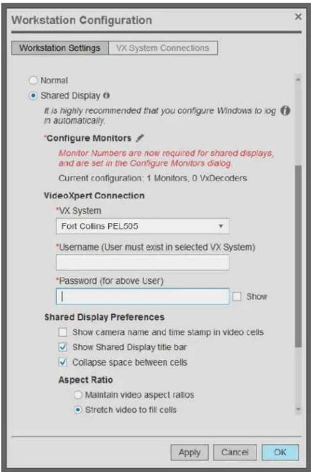
text_image
Workstation Configuration Workstation Settings VX System Connections Normal Shared Display It is highly recommended that you configure Windows to log in automatically. *Configure Monitors Monitor Numbers are now required for shared displays, and are set in the Configure Monitors dialog. Current configuration: 1 Monitors, 0 VxDecoders VideoXpert Connection *VX System Fort Collins PEL505 *Username (User must exist in selected VX System) *Password (for above User) | Show Shared Display Preferences Show camera name and time stamp in video cells Show Shared Display title bar Collapse space between cells Aspect Ratio Maintain video aspect ratios Stretch video to fill cells Apply Cancel OK- Click the Configure Monitors icon (√), and then configure the monitors.
a. Click to select the monitor.
b. Click to select the radio button for Direct.

text_image
Configure Monitors 2 3 1 Connection Type • Direct (monitor is connected directly to the computer) • Decoder (monitor is connected to an Enhanced Decoder) IP: Connect VX System Monitor Number ? 32 ✓ Auto-accept all shared video streams and views ✓ All monitors successfully connected. Cancel DoneFigure 3: Connecting Monitors
c. If you are going to allow remote control of a selected monitor, assign a number to the monitor. To do so: enter a number in the VxSystem Monitor Number field, and then click to select or deselect the checkbox for Auto-accept all shared video streams and views. When Auto-accept all shared video streams and views is selected, the monitor will automatically accept video streams and views that have been sent by another workstation or shared display; when it is not selected, a user must manually accept shared video streams and views on the monitor.

Note: You must assign a unique number to a monitor (workstation or shared display) if you will send video to it remotely. However, Pelco recommends that poly do so under these circumstances. When you set a monitor number, every change made to that window will be sent to the server. This is an unnecessary load if you are not using the monitor as part of a monitor wall.
The example above shows the assigned monitor number (32) in the lower right corner of the monitor.
-
Provide a number for the monitor. The number will allow you to set rules to send video to your shared display, or to send video to the shared display by number.
-
(Optional) Enter or select a VX System to create a VideoXpert Connection. Selecting this option opens a dialog to configure system server connections.
-
Provide the user name and password of an account with credentials to view video; the account provided must have access to cameras and functions you want to use through the shared monitor, and must have the Manage Display Devices permission enabled (via VxToolbox in >Users>Users>Device Management>Manage Display Devices).
-
(Optional) Click the checkbox to select or deselect Show camera name and time stamp in video cells. Whether the user sharing video has names and timestamps enabled, the shared display uses this preference to determine whether or not to display overlays.
-
(Optional) Click the checkbox to select or deselect Show Shared Display title bar.
-
(Optional) Click the checkbox to select or deselect Collapse space between cells.
-
In the Aspect Ratio area, click to select the radio button to either Maintain video aspect ratios or Stretch video to fill cells.
- (Optional) click the checkbox to select or deselect Enable hardware acceleration. Hardware acceleration is enabled by default and should only be disabled if your workstation uses an unsupported graphics chipset, or if you need to troubleshoot graphics issues that may result from your graphics drivers and chipset.

Note: Hardware acceleration of H.265 is supported on the Shared Displays VX-A3-SDD and newer, and Enhanced Decoders VX-A3-DEC and newer.
- (Optional) Click the checkbox to select or deselect Multi-System Access opens without initial credentials (MSA). In MSA mode, VxOpsCenter will open with no VX Systems connected. Credentials will be required when you connect to a VX system.
- Click Apply.
- Click OK.
Configuring VxOpsCenter™ Kiosk Mode (Optional)
You can run VxOpsCenter in kiosk mode, so that only VxOpsCenter Client will be run without access to any other Windows applications.
- The launcher and script are not included in the default installer of VxOpsCenter.
- To run in kiosk mode, install VxOpsCenter on a machine with Windows 10 operating system using VxOpsCenter 2.5 or later.

Caution: If not done properly, this process might result in a loss of critical data. In addition, the process has several complex steps that, if not done properly, might result in unforeseen results. Before beginning this process, ensure that all important data is backed up. If you are uncertain of this process or are unfamiliar with the requirements, contact Product Support Services for assistance.
To install and configure VxOpsCenter to run in kiosk mode:
- Install VxOpsCenter v 2.5 or later on a Windows 10 PC.
- Refer to the white paper Configure VxOpsCenter Kiosk mode.
- From the white paper, download OpsCenterLauncher.zip and kiosk_mode_script_v2.ps1.
- Unzip OpsCenterLauncher.zip and copy the files to the VxOpsCenter directory at c:\Program Files\Pelco\VideoXpert\VxOpsCenter.

Note: The path must be the same as the path specified in kiosk_mode_script_v2.ps1.

Note: If the OpcCenter Client kiosk mode is updated to a newer version, copy the contents of OpsCenterLauncher.zip to the folder again.
- Create a local standard user account called "Operator".

Note: The account must be the same as the account specified in kiosk_mode_script_v2.ps1.
- Run kiosk_mode_script_v2.ps1 as the Windows Administrator.
Logging In
Open the VxOpsCenter application.
- (Optional) If VxOpsCenter is configured to connect to a single system at a time, select the system you want to access. See the section titled Understanding User Account Types.
-
(Optional) If VxOpsCenter is configured for multi-system access, select Multi-System Access Mode from the drop-down list in the Connect to System field.
-
The first time you login to the system using Multi-System Access Mode, you will be asked to select a system for authentication.
- When you log in subsequently using Multi-System Access Mode, you will be connected to the systems to which you've connected before.
-
If Mutli-System Access opens without initial credentials is enabled in VxToolbox, you can log in using Multi-System Access Mode without using any credentials, but you will not be connected to a VX system. When you connect to a VX system, credentials are required.
-
Enter your credentials.
-
Click Log In.

Note: If one or more licenses associated with the VideoXpert system are nearing or past the expiration date and require renewal, a warning dialog box will open. The dialog box lists the affected license(s) and the expiration date. Make a note of this, and then click Remind Me Later to close the box. Optionally, click Dismiss Selected (if present), to stop the warning from appearing. Notify your system administrator of the pending expiration.
Understanding User Account Types
VxOpsCenter supports two types of users:
- The Workstation Configuration account provides access to VxOpsCenter settings and allows you to configure connections to VX systems. The configuration account should be reserved for administrators, especially if multiple users will share the same workstation.
- Logging in as a standard VX system user provides access to standard VX features - viewing video, controlling cameras, etc.

Note: If multi-system access is enabled, only Workstation Configuration accounts are supported.
If your user account is both the Workstation Configuration account and a VX system user, VxOpsCenter will log you into applicable VX systems and allow access to workstation configuration settings.
When you log in as a standard VX system user, the system will only populate sources and options you have permissions to see (determined by the roles assigned to your user account). If a system or camera does not appear when you log in, then the system or camera might be offline, or you might lack the appropriate permissions.
Setting Your Display Language
The localization presented by the VxOpsCenter client is based on the Region and Language settings within Windows.

Note: You must have the appropriate Windows language pack to expose display languages in the VxOpsCenter Client.
To set or change your VxOpsCenter display language:
- Close the VxOpsCenter software if it is already running.
- Click Start (if necessary), and then search for and click to open Language settings.

Note: These steps might be different, based on the operating system you are using.
- Click to select a language from the Windows display language drop-down menu.
- If the appropriate language is not present, click Add a windows display language in Microsoft Store. Follow the prompts to add the appropriate language, and if appropriate, click to select the checkbox for Set as my Windows display language.
- Close the Settings window.
- Run the VxOpsCenter Client.
Changing Your Workstation Account Password
If a password expiration policy is in place (for example: your password expires every 90 days), you will see a warning dialog box when your password must be changed.

Note: Password expiration is not used with Single Sign-On (SSO). If your system is configured to use SSO, or if the expiration policy is set to Passwords never expire, then you will never see the warning dialog box.
- In the warning dialog box, click Change Password.
- In the Change Password dialog box, enter values in the Current Password, New Password, and Retype New Password fields.
- Click Save.
If you are resetting the password, and are not doing so from the password expiration warning dialog box:
- In Mission Control, click the User Menu icon (▼), and then select Configure Workstation.
- If necessary, enter an administrative Username and Password, and then click Authenticate.
- Click Workstation Settings.
- In the VX Workstation Account area, in the Password field, enter a new password.
- Click Apply.
- Click OK.
Using the VxOpsCenter™ Interface
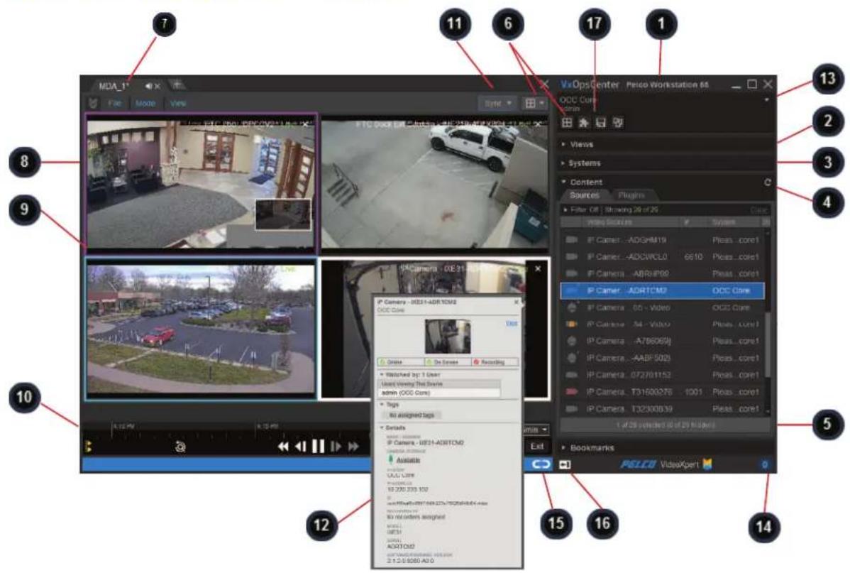
text_image
Screenshot of a video editing software interface with numbered annotations pointing to various camera and system settings.| 1 | Mission Control contains settings, and all the items with which you may populate workspaces. |
| 2 | The Views panel provides access to New Tabs, Saved Tabs, and Workspaces. Your workspace consists of tabs and monitors populated with cameras or plugins. You may have one active workspace at a time containing some number of tabs (typically one tab per monitor, but that is not a limitation); each tab contains some number of video streams or plugins. |
| 3 | The Systems panel enables you to add or edit system connections. It also provides access to the Systems List window, which enables you to filter and sort the systems to which you are connected. This panel is available only when running in multi-system access (MSA) mode. |
| 4 | The Content panel provides access to the Sources tab, which shows all the video sources that the current user can access. Use the filters in the panel to sort the list in real time. The Maps tab provides access to Maps that are available on the system. The Plugins tab contains content and overlay plugins. Some plugins consume a cell, like the Image Viewer plugin. Overlay plugins operate in the same cell as video, providing additional information about the video in question. |
| 5 | The Bookmarks panel shows clips of video that you or other users have bookmarked. Use the filters in the panel to sort the list in real time. |
| 6 | The Select Grid Layout controls or the New Tabs panel determine the number of cells in a tab. |
| 7 A | Tab is a window of the VxOpsCenter containing cells. |
| 8 | A Cell displays a single camera or plugin within VideoXpert. Cell highlights and borders indicate whether a cell is selected, playing-back video, or is in PTZ mode. |
| 9 | Playback Controls and the timeline in a selected cell applies to that cell only. |
| 10 | Playback Controls and the timeline at the bottom of the tab applies to all synchronized cells within the tab. |
| 11 | Synchronous Play enables you to select cells for which playback is synchronized. |
| 12 | Tooltips show additional information about your video sources. Hover over entries in the Sources and Bookmarks panels to reveal tooltips. |
| 13 | The User Menu contains preferences and controls specific to the current user. Through this menu, you can open application Preferences, the Export Archive, the View Launcher, and other user options. |
| 14 | The Event Counter shows how many active events that require response from you or someone with similar permissions. |
| 15 | The Undock Mission Control icon 📋 undocks Mission Control from its current location. When it is undocked, the Dock Mission Control icon 📋 docks it to any tab in the workspace. |
| 16 | The Move Mission Control to the Left 📋 icon is visible when Mission Control is in the default position (right panel), and moves it to the left panel. The Move Mission Control to the Right icon 📋 is visible when Mission Control is in the left panel, and moves it to the right panel. |
| 17 | Quick access to frequently used tools are provided in Mission Control, just above the Views panel. Click the corresponding symbol to get to New Tabs 📋, Plugins 📋, Saved Tabs 📋, and Workspaces 📋). |
Adding Quick Access Icons to Mission Control
Quick access to frequently used tools are provided in Mission Control, just above the Views panel. They can be added and removed. To add or remove the quick access icons:
- In Mission Control, right-click in the space above Views.
- Click to select (to add) or deselect (to remove) a tools icon.
- Repeat these steps to add or remove another tools icon.
Using Context Menus
Right-click entries in the source list or cameras in your active workspace to reveal additional options available to your user and the devices you want to use. VxOpsCenter provides users with only the options available to you at any given time; availability may be limited by factors including your user permissions, the types of cameras you use, and whether or not PTZ mode is engaged. Options include the following.
- Send To enables you to choose a view to send (a saved tab, saved investigation, or workspace), a destination for the view, and whether to force acceptance of the sent view. See the section titled Sending Views to Workstations™ or Shared Displays™.
-
Quick Export lets you export a recording of the Previous 5 minutes, the Previous Minute, or a Custom start and end date and time, from either the item in the Sources panel for from a cell timeline. From the timeline, you can also export a recording of the Next minute and the Next 5 minutes. See the section titled Using Quick Export.
-
Edit Source enables you to assign the selected source a new name or number.
- Manage Tags shows you what tags are assigned to the selected camera(s), system, and folders; and lets you filter which tags to show. See the section titled Managing Tags.
- Open Camera Configuration in Browser opens the camera Web UI, and enables you to login and make changes to the camera configuration. Refer to the camera operations manual.
- Open in VxToolbox opens VxToolbox to the corresponding system, and highlights the source in the Devices (center) panel. Refer to the VxToolbox section of this manual.
- Rotate lets you select the default rotation, 180 degrees, or plus or minus 90 degrees. See the section titled Rotating the Camera.
- Analytic Overlays, Simple & Enhanced lets you toggle Simple Motion Detection and Analytic Drawing Data on and off to display or hide analytics overlays on some Pelco cameras. See the section titled Viewing Analytics Overlays.
- Analytic Overlays, Advanced lets you toggle Object Bounding Boxes, Object Detection Zones, and Counting Lines on and off to display or hide these analytics on some Pelco cameras. If you toggle Counting Lines on, you can also toggle Display Counts on and off. See the section titled Viewing Analytics Overlays.
• Diagnostics lets you toggle:
- Statistics to display or hide camera statistics including such things as bitrates, mode, source, and call-up time. See the section titled Displaying Statistics.
- Measure Latency to determine the end-to-end latency of the source. See the section titled Measuring Latency.
- Relays to activate or deactivate a relay on the device.
- Home Preset returns the camera to the home position. See the section titled Executing PTZ Presets and Patterns.
- Presets lets you select an existing preset position, edit an existing preset position, and create a new preset position. See the section titled Executing PTZ Presets and Patterns.
- Pattern enables you to run an existing pattern. Patterns must be created on the camera. Refer to the camera operations manual.
- Refresh Presets and Patterns retrieves the list of presets and patterns from the camera. It does not overwrite or delete any patterns created from VxOpsCenter.
- Send Preset Number will send a preset to a specified cell in a specified monitor; and can display the data source, jump to a specified time, and trigger a preset. See the section titled Sending Views to Workstations™ or Shared Displays™
- Search Recordings for Motion (Pixel Search™) is available in VideoXpert Professional only, and allows you to quickly find search for motion in a camera recording. See the section titled Using Pixel Search™.
Using Tooltips
Hover over any bookmark in a cell or in the Bookmarks panel to reveal additional information about the bookmark. This information might include:
• The name of the bookmark
• The name of the device
• The date and time at the middle of the bookmark recording time
• An image from the recorded bookmark
Hover over the device symbol on any source in the Sources panel to reveal additional information about the source, including:
• The name of the source
• The current image of the source (if enabled)
- Whether or not the camera is Online, On Screen, and Recording, and whether PTZ is locked (if the camera has PTZ)
• Watched by information
- Tags associated with the source (if any)
- Technical Details such as: whether or not there is camera storage, the IP address, the camera ID, the target location for recording (if any), the camera model, the camera serial number, and the camera software version
Click on View, if present, to display the source in a cell.
Using Watched By
If you have the "Multiview" permission, you will see a Watched by field in tooltips throughout the VxOpsCenter interface. The Watched by field shows users watching live video from a particular video source; the Watched by field does not show users playing back video recorded from a video source.
If the users listed in the Watched by field are viewing video from a different site than you, the tooltip will also attempt to indicate the site from which other users are watching video. If users are watching video from an aggregated site, the tooltip will state the site name in parenthesis. If you are watching video from an aggregated site, and the users listed in the Watched by field are accessing VideoXpert from the Aggregation (parent) site, then the tooltip will simply list parent site.
Setting User Preferences
When logged in to VideoXpert, you can set some basic preferences for behaviors within the VxOpsCenter application. To access the Preferences window:
- In Mission Control, click the User Menu icon ( ).
- Click Preferences.
The Preferences window opens.
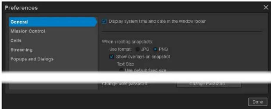
text_image
Preferences General Mission Control Cells Streaming Popups and Dialogs Display system time and date in the window footer When creating snapshots: Use format: JPG PNG Show overlays on snapshot Text Size Use default fixed size Change user password Change Password... DoneUpdating General Settings
- In Mission Control, click the User Menu icon ( ).
- Click Preferences.
-
In the Preferences window, click General.
-
(Optional) Click to select the checkbox to enable Display system time and date in the window footer.
- (Optional) In the When creating snapshots area:
a. Click to select the radio button for JPG or PNG.
b. Click to select or deselect the checkbox for Show overlays on snapshot. If you select this option, also configure the following settings:
- Under Text Size, click to select the radio button for either Use default fixed size or Scale text as a percentage of snapshot height. If you select scaling the text, enter a percentage in the field, either by typing-in a number or selecting one using the up and down arrows.
- Select a Position from the drop-down menu.
- Use the slider bar or type in a value to select the Opacity of Text Background.
- In the Text color area, click to select the radio button for Use default colors or Use white for both camera name and timestamp.
-
Click to select or deselect the checkbox for Auto-save snapshots. If you select this option, enter the folder location to which the snapshots will be saved either by typing in the path or using the Browse button.
-
(Optional) Click Reset Tips and Warnings, and then click OK in the Reset Warnings confirmation window.
- (Optional) Click Change Password, complete all fields in the Change Password for [user] dialog box, and then click Change Password.
- Click Done to exit the Preferences window.
Updating Mission Control Settings
- In Mission Control, click the User Menu icon ( ).
- Click Preferences.
- In the Preferences window, click Mission Control.
- (Optional) Click to select and deselect radio buttons in the When double-clicking a source... area, to control how a source is opened.
- (Optional) Click the checkbox to select or deselect Allow docking Mission Control via drag-and-drop.
- (Optional) Click the checkbox to select or deselect Highlight source of the selected cell in the source list. If you select this option, you can also select Automatically scroll source list to reveal highlighted source.
- (Optional) Click the checkbox to select or deselect Show video thumbnails on hover in the source list.
- Click Done to exit the Preferences window.
Updating Cells Settings
- In Mission Control, click the User Menu icon ( ).
- Click Preferences.
- In the Preferences window, click Cells.
-
In the Display camera info in video cells as section, click to select the radio button for Camera Name, Camera Number, Camera Name / Camera Number, or Camera Number / Camera Name.
-
(Optional) Click to select or deselect the checkbox for Always show camera info in cell. If you select this option, you can also select Show overlay behind persistent camera info in cell.
- (Optional) Click to select or deselect the checkbox for Display "Live" rather than timestamp in cell when showing live video.
- (Optional) Click to select or deselect the checkbox for Automatically enter PTZ mode upon loading source in cell.
- (Optional) Click to select or deselect the checkbox for Display in-cell feedback for playback controls.
- (Optional) Click to select or deselect the checkbox for Collapse space (gutters) between cells.
- (Optional) Click to select or deselect the checkbox for Display timestamp above timeline playhead.
- In the When placing multiple cameras area, click to select the radio button for Replace video content and create new tabs as needed or Only fill empty cells and create new tabs as needed.
- (Optional) Click to select or deselect the checkbox for Automatically play audio when available.
- If you selected it, click to select the radio button for From selected cell only or From all visible cells.
- If you deselected it, the From selected cell only or From all visible cells radio buttons are not available.
- (Optional) In the Advanced Analytics area, click to select or deselect the checkbox for Always show zones in alarm state. This option will always show zones that are in an alarmed state, for all video cells that are streaming configured Advanced Analytic cameras.
For example: when this preference is checked, any detection-zone that is occupied will show up as an overlay in an alarmed state and will disappear when the zone is no longer occupied. If a user selects the Show Object Bounding Boxes and/or the Show Object Detection Zones context-menu items in a video cell, those selections take precedence over this setting, and will show all overlays for the user-selected options in that cell. If these cell-based options are deselected, this will return the cell to the configured user preference. - (Optional) In the Video aspect ratio area, click to select the radio button for Maintain video aspect ratios or Stretch video to fill cells.
- (Optional) For PTZ cameras, in the Immersive/Panoramic Video area:
a. Click to select or deselect the checkbox for Show immersive PTZ reference on panoramic image.
b. If there are Optera® cameras on your system, the Start Optera streams as option is displayed. Click to select the radio button for Immersive only, Panoramic only, or Panomersive. This sets the default streaming state.
- Click Done to exit the Preferences window.
Updating Streaming Settings
- In Mission Control, click the User Menu icon ( ).
- Click Preferences.
- In the Preferences window, click Streaming.
-
Click to select or deselect the checkbox for Decrease video buffer for live streams when in PTZ mode.
-
In the When playing back over a low-bandwidth connection area, click to select the radio button for Decrease frame-rate to match the network capability or Play at full frame-rate, but stop playback to buffer as needed.
- Click Done to exit the Preferences window.
Updating Popups and Dialogs Settings
- In Mission Control, click the User Menu icon ( ).
- Click Preferences.
- In the Preferences window, click Popups and Dialogs.
- Click to select or deselect the checkbox for Sort alerts by severity level instead of timestamp.
- Click Done to exit the Preferences window.
Using Tabs and Workspaces
A workspace is comprised of tabs; each tab consists of a layout populated with sources and plugins. You can save your entire workspace or individual tabs for easy access later. Users with appropriate permissions can even make their workspaces or tabs arrangements available to other users. The server automatically saves your workspace when you log out, and recalls it when you log in again.
Using Tab View Options and Modes
For each tab, use the Mode and View menus to control the display.
Configuring Tab View Options
To update view options for a tab, select the tab (in the image above, the tab is named LinkedPTZ), click View, and then select one or more of the following options:
- (Optional) Select whether to display the tab in Full Screen mode—the tab controls and outer borders vanish, maximizing the size of video and cells.
- (Optional) Set the Max Video Quality within the tab. Unless the tab is in collaborative mode, video quality settings affect video locally; they will not determine the behavior of a tab displayed on another user's workspace or a shared display.
- Highest Available Quality sets the tab to behave normally; it will display the camera's primary stream when possible, as dictated by cell size and system resources.
- Secondary Stream forces the tab to display a maximum video quality of secondary for all cameras.
- Tertiary Stream forces the tab to display a maximum video quality of tertiary for all cameras. (The cameras can display tertiary or the highest available video quality below tertiary.)
- D1 (720 x 480) displays video at 720 x 480 resolution.
- SIF (352 x 240) displays video at 352 x 240 resolution.
- JPEG Stream sets the tab to have all streams transcoded into JPEG frames. The rate of the JPEG stream is dependent on network bandwidth and Media Gateway availability; this setting can be stressful on your Media Gateway.
- Thumbnails sets the tab to images that refresh roughly every 30 seconds, rather than video. This mode uses few resources and significantly reduces the impact of the tab on your workstation. Use this mode for large areas in which a low frame rate is still enough to capture activity within the scene.
If necessary, the system will downgrade one or more video streams that are displayed in the cells. When this happens, the orange downgraded stream icon (☐) is displayed to the right of View in the tab task bar. Click the icon to allow the system to attempt to restore the initial video quality to each cell.
- (Optional) Click to select either Stretch video to fill cells or Maintain video aspect ratios, whichever is not currently selected.
- (Optional) Click to select either Collapse space between cells or Show space between cells, whichever is not currently selected.
Changing Tab Modes
Tab modes determine the features available to you within a tab. Changing tab modes without saving the current tab will cause you to lose your settings. Modes are exclusive; for example: a tab cannot support a sequencing mode and also the collaborative mode. Putting the tab in either mode will remove the abilities granted by the previous mode. To change the mode, click Mode, and then click to select one of these options:
- Normal mode sets the tab to behave normally.
-
Collaborative mode allows you and other users to view and affect changes in the tab simultaneously; use this mode to collaborate with other users.
-
Collaborative tabs do not support plugins and are not available when multi-server access is enabled.
- Collaborative tabs are always public tabs; you cannot restrict the users who have access to the collaborative tab.
- Tabs marked with the Collaborative Tab icon (图标) are collaborative, and allow multiple users to view and affect changes in the tab simultaneously. User commands against the collaborative tab are performed on a first-come, first-served basis. Users should account for latency and the total number of collaborative users when affecting the tab to coordinate efforts.
- Live Sequence mode allows you to add more cameras to a tab than the layout would traditionally support, and to rotate cameras through the tab at a particular interval. See the section titled Creating a Live Sequence Mode.
- Alarm Sequence mode allows you to designate cameras that you want to watch only when a meaningful event occurs. See the section titled Creating an Alarm Sequence Mode.
Creating a New Tab
Creating a tab allows you to recall the complete tab, including all cameras, viewing states (live or recorded video), and plugins. Save tabs that you or other users will recall frequently.
-
Select a layout for a new tab by one of the following methods.
-
At the top of the workspace, to the right of all open tabs, click the New Tab icon (⊕), and select a layout.
- In Mission Control, in the quick access icons area, click the New Tabs icon (☐), and then click to select a layout.
-
In Mission Control, in the Views panel, click New Tabs, and then click to select a layout.
-
Populate the tab with sources or plugins. Use the filter function, if necessary, in Mission Control to find cameras to add to your workspace:
a. Click Filter to expand the view.
b. Type a value in the Filter by field.
c. Double-click a source or drag it to an empty cell.

Note: You can also drag cells to rearrange your workspace.
-
While viewing the tab to be saved, click File at the upper left corner of the window, and then click Save As.
-
Enter the following information:
a. A Name for the tab.
b. (Optional) Select a keyboard Shortcut.
c. (Optional) To make the tab available to all users in the VideoXpert environment, click to select the checkbox for Save as public tab.
d. (Optional) To make the tab globally available, and allow multiple users to view and simultaneously manipulate the contents of the tab, click Save as collaborative tab.
- Click Save.
Opening a Saved Tab
To open a saved tab:
- In Mission Control, click to expand the Views area.
- Click Saved Tabs.
- Double-click the tab you want to open, or drag a tab into the monitor in which you want it to open.
Updating an Existing Tab
You can make changes to an existing tab and then save the changes.
- In the tab you wish to update, make all necessary changes.
- Click File at the upper left corner of the window, and then click Save.
Changing Tab Layouts
The grid icon in any tab shows your current layout. Click it to select a new layout option. If you select a layout with fewer cells than your current layout, the client will retain camera-cell assignments and repopulate cells accordingly if you return to the original layout or a layout with more cells than the original.
- Select the tab to be changed.
- Click the Select Grid Layout menu next to the grid icon (☐) in the top right of the tab task bar.
- Select the new layout for the tab.
- (Optional) Click File, and then click Save to update the existing tab layout.
- (Optional) To create a new tab layout, click File, click Save As, update information in the Save Tab As dialog box, and then click Save.
Editing the Metadata of an Existing Tab
To edit the name, hotkey, or description for tabs:
- In Mission Control, under Views, click Saved Tabs.
- Do one of the following to open the Edit Tab dialog box:
-
Click to select the tab to edit, and then click the Edit Tab icon (√).
• Right-click the tab to edit, and then click Edit Tab. -
In the Edit Tab dialog box, edit the values as appropriate.
-
When complete, click Save.
Deleting a Saved Tab from the System
- In Mission Control, under Views, click Saved Tabs.
- Do one of the following:
- Click to select the tab, and then click the Delete Tab icon (☐).
• Right-click the tab, and then click Delete Tab.
- In the Delete Tab dialog box, click OK.
Creating a New Workspace
Creating a workspace allows you to recall the complete workspace, including all cameras, viewing states (live or recorded video), and plugins. Save workspaces that you or other users will recall frequently.
- In Mission Control, click Views, and then click Workspaces.
- Double-click the workspace that is similar to the one you are creating.
- To delete tabs from the workspace, click the X at the right of each tab that you do not want (to close the tab). Leave at least one tab open.
- Make appropriate changes to each remaining tab, if necessary.
- Add more tabs, as appropriate, using one of the following methods:
• To add a new tab, see the section titled Creating a New Tab.
- To add an existing tab: in Mission Control, under Views, click Saved Tabs, and then double-click the tab name.
- Make any other changes to the workspace. For example: undock, dock, or move Mission Control; change the mode; or change the view.
- Save the new workspace:
a. If necessary, click the Workspaces tab again.
b. Click the Save Workspace As +con ().
c. Enter a value in the Name field.
d. (Optional) Select a value in the Shortcut field from the drop-down menu.
e. (Optional) To make the workspace available to all users in the VideoXpert environment, click to select the checkbox for Save as public workspace.
f. Click Save.
Opening a Saved Workspace
Opening a saved workspace will close your current workspace; you can save your current workspace before you open a new one. If you set a shortcut for a saved item, you can also recall it using keyboard shortcuts. To open a saved workspace:
- In Mission Control, click Views, and then click Workspaces.
- Double-click the workspace to open.
- If the Recall a saved workspace dialog box opens, click to select Keep Open Windows or Close Your Open Windows.
Updating a Saved Workspace
- In Mission Control, click Views, and then click Workspaces.
- Open the workspace to update.
- To delete tabs from the workspace, click the X at the right of each tab that you do not want (to close the tab).
- Make appropriate changes to each remaining tab, if necessary.
- Add more tabs, as appropriate, using one of the following methods:
• To add a new tab, see the section titled Creating a New Tab.
- To add an existing tab: in Mission Control, under Views, click Saved Tabs, and then double-click the tab name.
- Make any other changes to the workspace. For example: undock, dock, or move Mission Control; change the mode; or change the view.
- If this is not a global workspace, or if you have permission to edit/update the workspace, save the updated workspace:
a. If necessary, click the Workspaces tab.
b. Click the Save Workspace Icon ().
c. In the Save Workspace confirmation dialog box, click Save.
Editing the Metadata of an Existing Workspace
You can edit the name or shortcut of a workspace, or change whether it is saved as a global workspace at any time.
- In Mission Control, click Views, and then click Workspaces.
- Click to select the workspace to edit, and then click the Edit Workspaces icon (√), or right-click the name of the workspace and then click Edit Workspace.
- In the Edit Workspace dialog box, make any needed changes, and then click Save.
Deleting a Workspace from the System
- In Mission Control, click Views, and then click Workspaces.
- Do one of the following:
- Click to select the workspace, and then click the Delete Workspace icon (☐).
- Right-click the workspace, and then click Delete Workspace.
- In the Delete Workspace dialog box, click OK.
Viewing a Monitor Wall
Monitor walls are specific groups of monitors that are frequently viewed or used together, and have been configured in VxToolbox as a tab so that users can easily access them.
The monitor wall is used to send cameras or streams to workstations or shared displays. The user opens the monitor wall and makes changes to the monitors in the wall. The changes are sent to the monitors instantaneously.
To access and use a monitor wall:
- Open a workspace to which you would like to add a monitor wall.
-
Open a the monitor wall tab by one of the following methods:
-
In Mission Control, click the New Tabs quick access button (☑), and then double-click or click and drag the monitor wall tab icon ( ).
- In Mission Control, click to expand the Views area, click New Tabs, and then double-click or click and drag the monitor wall tab on ( ).
-
At the tab bar at the top of the window, click the New Tab icon ( + ), in the Open New Tab area click the monitor wall tab icon ( ).
-
At the upper left corner of the monitor wall tab, select a pre-configured monitor wall from the drop-down menu.
- For each monitor in the wall, you can:
- Drag sources into a monitor cell.
Only monitors for which you have permission can receive camera streams.
- Change the tab grid layout by selecting an option from the Select Grid Layout drop-down menu or by dragging and dropping them from the New Tabs panel to the monitor.
- Click on the source name to display the tooltip for the source.
- Remotely control a cell in live and playback modes, using a standard keyboard, a KBD500 keyboard, and/or a 3D spacemouse.
-
When you are controlling a cell:
-
The numeric keypad on either keyboard (standard or KDB5000) brings up the call-up dialog. In a monitor wall, the call-up dialog is at the lower center of your monitor instead of in the cell you are controlling.
- More than one user (VxOpsCenter) can control cells in the monitor wall at one time. The cells outlined in green are being controlled by another user. The cell outlined in white is being controlled by you.
You cannot select cells on a monitor for which you do not have permissions.
- To refresh the tab, click the Refresh icon (C) at the upper right of the tab.
Working with Maps™
Maps ^™ provides an interface to arrange cameras according to their physical locations on a map, making it easier to find the right camera and view to suit your needs.

Note: Maps supports world drawings, DWG, JPEG (raster), and PNG (raster) images.
Before you use Maps, configure Maps in VxToolbox. Refer to the VxToolbox section of this manual.
Understanding Maps Permissions
Maps uses the View Maps permission within the VX system. Camera permissions are applied to maps as well. If a user lacks permissions to a particular camera, it will not appear on the map or in the list of cameras the user can add to a map.
Viewing a Map
To view a map:
- In Mission Control, click Content, and then click Maps.
- (Optional) Filter the maps that are displayed. To do so, enter a value in the Filter search box. To reset the filter, click the clear filter icon ( ) or Clear.
- Select the map by one of the following methods:
- Click and drag a map from the Maps panel to a cell.
• Double-click the map in the Maps panel.
Working In a Map
To use the map:
- View a map as described in the section titled Viewing a Map
- (Optional) Move the field of view of the map. To do so, click on the map and drag it until the appropriate view is displayed.
- (Optional) Use the scroll wheel on your mouse to zoom in and out.
- (Optional) Hover over a camera to view the camera name and a thumbnail. If the hover option is not working, it has been disabled. Enable it in the Preferences panel. See the section titled Setting User Preferences for Maps.
- (Optional) Hover over a map to view the map name.
- (Optional) Click on a camera in the map to view data for the camera. This opens a panel on the right of the cell. Data includes: the camera name, status, Watched by information, Tags, and Details (IP address, ID, recording data, model and serial numbers, and software/firmware version).
-
(Optional) Notice the status of the icons on the map.
-
An plain icon (gate, door, alarm, etc.) is online, with no events in progress.
-
An icon that has additional or different symbols—for example: it has a red X through it or a question mark over it; or it has been replaced by another symbol (alarm symbol, open door or gate, etc.)—indicates special status. View device data for details.
-
(Optional) Open a camera from the map. Double-click a camera icon to open it in a new cell.
-
(Optional) Press Ctrl and then double-click on a linked map icon () to open the map in a new cell.
-
(Optional) Click a linked map icon ( ) to open the map in the current cell.
-
(Optional) If you have more than one map available, you can select a different map to view in the current Map cell. In the Map field at the upper left of the cell, select a map from the drop-down list.
Setting User Preferences for Maps
At any time, you can change the user preferences for Maps.
-
View a map as described in the section titled Viewing a Map
-
At the upper right of the Maps cell, click the gear icon ( ).
-
(Optional) Under Automatic Map Display:
a. Click to select or deselect the checkbox for Center on Alarm.
b. If you selected Center on Alarm, click to select or deselect Switch map on alarm.
c. If you selected Switch Map on Alarm, click to select the checkbox for either Ask every time or Automatically switch.
d. Change the Map zoom level by clicking and dragging the slider bar (if present).

Note: You cannot change map zoom level world maps.
- (Optional) Under Appearance of this map:
a. Click to select or deselect Show camera numbers.
b. If you selected Show camera numbers, select a Camera number color from the drop-down menu.
c. Adjust the Map Background Color by selecting a color from the drop-down menu.
d. Change the Scale of Icons by clicking and dragging the slider bar.
e. (Optional) Click Restore Defaults to return to the default settings for the map.
-
Click to select or deselect the checkbox for Show video thumbnail on hover. On the VxProfessional systems, the thumbnail is always shown on hover.
-
Click outside the Preferences panel to close it.
Sending Views to Workstations™ or Shared Displays™
You can send cameras or tabs to other workstations or shared displays (destinations) in your VideoXpert network using View Launcher or Quick Launch.
Using View Launcher to Send Views to Workstations™ or Shared Displays™
To use the View Launcher to send cameras or tabs to other workstations or shared displays in your VideoXpert network:
-
Open the View Launcher using one of the following methods:
-
In Mission Control, click the User Menu icon (▼), and then select View Launcher.
- Click the source in the active cell, click File, and then click Send To.
• Right-click the source in the active cell, and then select Send To. - Right-click the device icon in of the appropriate source in the Sources list, and then select Send To.
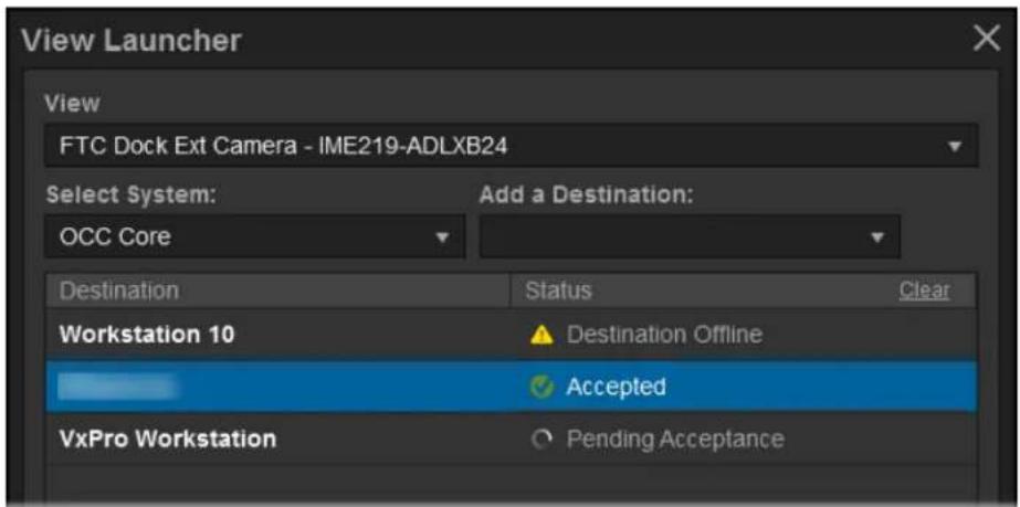
text_image
View Launcher View FTC Dock Ext Camera - IME219-ADLXB24 Select System: OCC Core Add a Destination: Destination Status Clear Workstation 10 ▲ Destination Offline ✓ Accepted VxPro Workstation ○ Pending Acceptance
text_image
Force acceptance Launch- Use the drop-down menu to select the View that you want to send if it is not already selected. If present, you can also select Saved Tabs, Saved Investigations, or Workspaces.
- If present, use the drop-down menu under Select System to select the system on which resides the destination for the view you want to send.
- Use the drop-down menu under Add a Destination to select destination for the view you want to send; destinations marked by are shared displays. You can select multiple destinations. When you have added all appropriate destinations, click outside the drop-down menu.
- (Optional) To clear a single destination from the list, click the x at the right of the destination row.
-
(Optional) To clear the destination list, click Clear.
-
(Optional) Select Force Acceptance to automatically launch the view in the active window of the destination.
The destination user might have to manually accept the view you send, the destination might be set to accept the view automatically, or you can force the destination to accept the view.
-
Click Launch.
-
The disposition of the sent view is listed in the Status column.
-
Click the close window ic( ) to exit the View Launcher.
Using Quick Launch to Send Cells to Workstations™ or Shared Displays™

Note: The Quick Launch dialog box has other functionality, which is explained in the tasks associated with those functions.
To use the quick launch feature, your shared displays must be assigned numbers. See the section titled Configuring Shared Display™ Mode
-
(Optional) If you are sending the currently streaming camera (you will click to select the cell to be sent), put the camera in the mode you would like to send. That is, you can leave the camera in live mode, select playback mode, and select a specific time in the recording to begin playback. When the cell is sent, the destination will appear as you set it now.
-
To access Quick Launch, (optional) click the cell to be sent, and then press the Insert key.
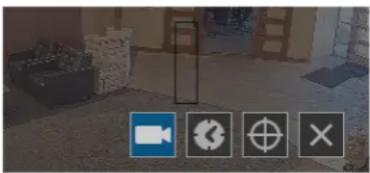
natural_image
Exterior view of a building interior with four icons: video camera, gear, crosshair, and X (no text or symbols)-
In the black box at the center of the dialog box:
-
Enter the target monitor number and then m to indicate the destination.
- (Optional) Enter the target cell number and then c. If you want the stream to appear in the 1st cell of the destination, you do not have to specify the cell number.
- If you want to specify a source other than a currently streaming camera in which you have clicked before opening Quick Launch, enter the camera number. If you specify the camera number, the destination will receive the cell in live mode.
Entering 6m3c222 would send camera 222 to cell 3 of monitor 6; entering 6m would send the currently selected camera to cell 1 of monitor 6.
-
Click the Call Up Camera icon ( ) or press the Enter key.
-
To close the Quick Launch dialog box, click the Cancel icon (✗).
Watching Video
The Sources section of Mission Control shows the list of video and audio sources you are authorized to access.
If a particular source is online but does not appear in your source list, try refreshing the list. Sources that come online after you log in or perform a search will not appear until you refresh the list. If the source still does not appear, request access to the source from your administrator.
When watching live video, cells 1/4 the size of the tab or larger will use the primary stream from a video source. Cells smaller than 1/4 the size the tab will use the secondary or tertiary video stream. In a 2x2 layout, for example, all cells will use the primary stream. In a 1+12 tab, the largest cell will use the primary stream and the other twelve will use the secondary or tertiary stream.
All-frame reverse playback enables frames to be displayed at up to eight times the normal speed. This will make the playback smoother.
When playing forward or reverse at high speeds (greater than +/-8X), only iFrames will be shown. At lower speeds, all frames will be shown whenever possible, but for reverse playback, some additional limitations apply:
- For systems that use enhanced decoders, this is available for up to four streams per monitor.
- For systems with multiple monitors on a single host, this is available for up to four streams total on the host PC.
- Reverse playback may be noticeably choppy for cameras configured with dynamic-GOP-length (a smart-compression feature) or for cameras with fixed-length, but unusually long GOPs. All cameras should work well with fixed-length GOPs up 15, or up to 30 for cameras with resolution less than 4K.
To watch live or recorded video, in Mission Control:
- (Optional) If VxOpsCenter is configured for multi-system access, you can shorten the list of sources available in the Content panel, and then limit the systems with which you are working:
a. In Mission Control, click Systems.
b. Click Filter to expand the filter panel.
c. If there is an active filter, clear it.
d. Click to select and deselect the systems to access.
The items in Sources page of the Content panel are updated immediately.
See the section titled Working With Systems.
- Click Content, and then click Sources.
- Find the source you want to watch. To use the Filter to search for sources:
a. Click Filter to expand the filter panel.
b. Type a value in the Filter by field or select a saved filter from the Advanced Filter Options dropdown menu.
c. (Optional) Click to expand Advanced Filter Options, and then refine the filter using the Tags, Online, Recording, On Screen, and Storage filters.
d. (Optional) To save a filter, under Advanced Filter Options, in the Saved Filter Sets drop-down menu, click Save Filter.
-
Add the camera to your workspace.
-
Drag a camera to the cell in which you want it to appear.
- Double-click a camera to add it to the next available cell in the current tab.

Note: If you add a PTZ camera that is offline, the cell displays PTZ controls are currently unavailable error message. Click OK to acknowledge the message. The cell will display source is offline the source comes back online.
Understanding Cell Borders
The color of the inner and outer border of a cell indicates the status of the cell.
- A white outer border indicated that the cell is active (selected); a black outer border indicates that the cell is not active.
- A white inner border indicates that the cell is in live mode.
- A yellow border indicates that the cell is in playback mode.
- A purple border indicates that the cell is in Digital PTZ mode.
- A blue border indicates that the cell is in PTZ mode.
- A flashing red border indicates that there is a notification for the device. To close the flashing red border, respond to the event notification.
- In monitor walls only, a green border indicates that the cell is being controlled by another instance of VxOpsCenter.
Responding to an Alarm in a Cell
If your workspace has been configured do to so, it will display a red alarm symbol for each active alarm at the left margin of a cell for a camera you are viewing. The inner cell border will flash red.
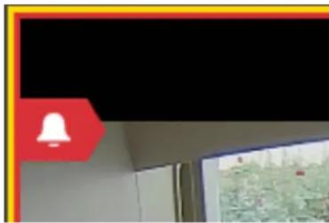
natural_image
Interior view of a room with a red bell icon and a computer monitor displaying a map (no visible text or symbols)Hover over the alarm symbol to see the alarm type.
To respond to the alarm:
- The event notifications pop-up window will display. If it does not, click the event counter at the bottom right corner of the VxOpsCenter window. When there are one or more active alarms, the event counter is red.
- Click on Event Log in the Event Notification window.
- Use the Event Notification dialog box or the Event Viewer cell to manage the alarm(s). To do so, see the section titled Using the Event Notifications Dialog Box.
Rotating the Camera
You can rotate the view of PTZ cameras. To do so:
- Right-click in the cell in which the camera is streaming, and then click Rotate.
-
Click to select one of the following options:
-
Maintain the Default Rotation
- Rotate 90^
- Rotate 180^
- Rotate -90°
Viewing Analytics Overlays
Pelco's Sarix cameras provide for an overlay of analytics on live and recorded video that can be displayed in VxOpsCenter. The types of analytics overlays are Simple & Enhanced and Advanced.
Simple & Enhanced overlays are as follows.
- Simple Motion Detection shows a red-tinted shape overlaying the video where motion is present.
• Analytic Drawing Data shows lines, boxes, and text to track areas of motion within the scene.
Advanced overlays are as follows.
- Object Bounding Boxes outlines and follows persons detected in the configured Person Detection Zones or vehicles detected in the configured Vehicle Detection Zones. Bounding boxes are shown for any object (person/vehicle) that is detected in the camera's view.
- Object Detection Zones shows the configured Person Detection Zones and Vehicle Detections Zones, and Counterflow zones (person or vehicle).
- Person In Zone bounding boxes are outlined in blue; when occupied, the corners of the bounding boxes will be red, as will the zone border. An event will be named Person in Zone " [name of zone]".
- Vehicle In Zone bounding boxes are outlined in orange; when occupied, the corners of the bounding boxes will be red, as will the zone border. An event will be named Vehicle in Zone " [name of zone]".
- A Person Counterflow or Vehicle Counterflow zone has green and red arrows in the center of the zone to show correct and wrong directions. The zones for person detection are outlined in blue; the zones for vehicle detection are outlined in orange. When one or more people or vehicles are moving in the wrong direction, the bounding boxes for each person or vehicle change to red and will show the full rectangular border. An event will be named Person Counterflow in "[name of zone]" or Vehicle Counterflow in "[name of zone]".
- Enabled Person Counter lines are blue; enabled Vehicle Counter lines are yellow. A counter can be uni-directional, bi-directional, or omni-directional, such that any person or vehicle crossing the line in the selected direction(s) will be detected. The direction is indicated by arrows along the line. You can hide or display the line count--how many people or vehicles have crossed the lone in the appropriate direction(s).
- A cell containing a detection zone in which an appropriate object is detected will have a yellow border around the cell.
- Object detection events are shown in VxPortal, but the overlays are not.

Note: For PTZ cameras, these are in presets that contain analytic configurations.

Note: Overlays are not available in exported recordings.
Overlays are configured at the camera level. Configuration parameters include the type of overlays that are enabled, the shape of each overlay in the overlay type, and sensitivity to motion. Refer to the operations manual for the camera to configure simple-motion data analytics and analytics drawing data. Refer to the current version of the VxToolbox™ Operations Manual or the VxToolbox section of this operations manual to configure Advanced overlays.
Analytics overlays can be enabled on a per-cell basis. That is, you can have more than one cell streaming video for the same camera, and set each cell to display (or not display) different analytics.
To view an analytics overlay in a cell:
- Open the camera in a cell.
-
Right-click the cell, click Analytic Overlays, click Enhanced, and then click to select Object Bounding Boxes, Object Detection Zones, and/or Counting Lines. If you select Counting Lines, you can also click to select Display Counts.
A check mark is displayed to the left of the option you select, indicating that the overlay is enabled. -
If appropriate, repeat the previous step and select another overlay.
-
(Optional) To disable an analytics overlay, perform the steps above, but click to deselect the overlay (s) that you do not want to display.

Note: Overlays will still be recorded even when they are disabled, so you can view them in playback mode.
Enabling and Disabling Audio
Video sources marked with a small blue or gray dot ( ) are associated with an audio source. In any cell containing or associated with an audio source, click the Mute/Unmute icon ( ) to enable or disable audio within a cell; you can control volume through Windows' standard audio controls.
To change the audio preferences on one or more cells:
- In Mission Control, click the User Menu icon ( ).
- Click Preferences.
- In the Preferences dialog box, click Cells.
- Click to select or deselect the checkbox for Automatically play audio when available.
- Click to select From selected cell only or From all visible cells.
- Click Done.
Expanding a Cell to Full-Screen
In the source cell, double-click the cell or click the View Video in Full-Screen icon (☒) to expand a cell to the full-screen. Click the same icon (now labeled Exit Full Screen), double-click the cell, or press the Esc key to exit full-screen mode.
Watching Recorded Video With VideoXpert™
Users with sufficient permissions can access recorded video from any video source in a workspace. Placing the pointer on a cell containing a source with recorded video will reveal playback controls.
- Place your cursor over the cell containing the source with recordings that you want to watch.
-
Navigate to the date and time in the recording that you want to view using one of the following methods:
-
Click the Jump to Specific Date/Time icon (☐), specify or select the date and time, and then click Go.
- Click in the cell with the recording to playback, enter a value in military time (for example: for 9:45PM, enter 2145). As you do this, the Quick Launch dialog box opens. When the time is displayed in the black box at the center of the Quick Launch dialog box, click the Jump to Time icon 📄.
- Click at the appropriate spot in the timeline to quickly navigate to a different time in the recording. Green areas on the timeline represent recorded video.
- Drag the timeline into position to navigate to a different time in the recording. Green areas on the timeline represent recorded video.
- Use the playback controls to direct video playback.
- Click the Jump Back 30 Seconds icon (30) to jump back 30 seconds from the currently selected spot in the timeline.
- Click the Jump to Now Icon ( ) to jump to live video.

Note: If a user changes a camera from http to https settings or the opposite, there might be a recording gap of between five seconds and five minutes.
Watching Recorded Video with Edge Storage™
If your camera or video source is recording video locally (using a micro SD card or in concert with ONVIF Profile G), the timeline will display the camera storage icon ( ); the device tooltip will also alert you to multiple recording locations.
Click on the camera timeline to display the camera storage icon ( ), and then click the icon to open an investigation tab showing the camera's various recording locations as separate timelines.
You cannot view video while it is stored on the camera; you must push video from the camera to a VideoXpert Storage recorder, to view video stored on a camera. See the section titled Using Investigation to View Video Stored on a Camera's Local Storage.
Using Pixel Search™
Pixel Search ^™ enables you to quickly access motion detection events on a specific camera for a selected range of time in a recording.
- For the specific camera (one at a time) that has the events you want to view, ensure that you have set the Motion Detection analytic, Detect Motion setting to On Server in VxToolbox. See the current version of the VxToolbox™ Operations Manual for instructions.
- Display the camera in a cell in VxOpsCenter; expand the cell, if appropriate.
-
Right-click the cell, and select Search Recordings for Motion (Pixel Search).
-
In the dialog box, click to select the checkbox for Don't show again (if appropriate), and then click OK.
-
In the grid that now overlays the camera view in the cell, select one or more zones (squares) in the grid, using one of these methods:
-
Click to select a single zone.
- Click and drag to select multiple adjoining zones in a rectangular pattern.
- Hold down the Shift key on your keyboard, and click to select each zone. These do not need to be adjoining zones.
- Hold down the Shift key on your keyboard, click individual zones, and click and drag to also select groups of adjoining zones.
- To clear the selected zones, click the Clear Selected Zones icon (☐) at the upper left of the cell.
-
To search in the zones that you did not choose, instead of the zones you chose, click the Invert Selected Zones icon ( ) at the upper left of the cell.
-
To select a different date and time range than what is currently selected, click edit icon ( ) at the upper right corner of the cell, to the right of the date range; in the Set Time Range window, select a start date, start time, end date, and end time; and then click Set.
- The length of time included in the default time range is based on the current time bar selection. For example, if 1hr is selected in the time bar drop-down menu at the bottom of the workspace, then one hour will be the default time included in the search range. To change the length of time included, in the default time range, click the drop-down menu for the current time bar selection, and then click the appropriate time range.
- (Optional) To exit the Pixel Search, click the Cancel icon (×) at the upper left of the cell.
-
In the upper right of the cell, click Search.
-
The first event (chronologically) plays immediately.
- Clips with motion events detected are indicated by blue bars in the timeline in the playback controls area.
- The blue pixel search bars are half-height; motion is full-height.
- To jump to the next event, click the Alt key, and then click the Next Clip icon ( ) in the playback controls area.
-
To jump to any event, select an event from the Jump to Event drop-down menu at the top of the window, or click the blue bar associated with the event in the playback controls area.
-
When finished, click Done in the top right corner of the window.
Using Bookmarks
When watching recorded video, you can create a private or public bookmark to note a moment in video to reference later. Bookmarks appear in a section in Mission Control. Public bookmarks are global resources; all users can see the public bookmarks you create. Within Mission Control, bookmarks behave like cameras; you can add a bookmark to a tab or workspace to recall the portion of video captured by the bookmark.
Creating Bookmarks
To create a bookmark:
- While watching a recorded video, click the Create Bookmark icon (☐).
- Provide a Title for the bookmark. The title can be searched within Mission Control.
- (Optional) Enter information in the Notes field.
-
(Optional) Apply a lock to segments of video/audio recordings, called clips, to prevent them from being deleted unless they are purposely unlocked. To do so:
a. Click to select the checkbox for Lock Video.
b. Use the date and time selectors to set the start and end parameters for the lock. -
Click Save.
Finding and Recalling Bookmarks
Bookmarks behave like any other camera or video source. Adding a bookmark to a workspace adds the camera to the workspace in playback mode, paused at the date and time specified by the bookmark.
- Click Bookmarks in Mission Control to expand bookmark resources.
- (Optional) Use the filters to search for a bookmark. The list of results only displays the source, date, and time for the bookmark in question, but you can also search by the plain-text note attached to the bookmark. Hover the cursor over a bookmark to get more information about it.
- Add the bookmark to a tab or workspace.
- To see the lock on the timeline, scroll to a time within the lock, and notice the white bar at the top of the timeline, with arrows pointing down to indicate the start and stop times.
Editing, Unlocking, and Deleting Bookmarks
To edit the plain text for the bookmark or to lock or unlock the bookmark, select the bookmark in Mission Control and click the Edit Bookmark icon ( ), you cannot change the date, time, or camera.
To delete a bookmark, select it in Mission Control, click the Delete Bookmark icon (☐), and then click Delete.
Synchronizing Video Playback
You can synchronize playback across multiple cells within a tab to provide different perspectives for a single recording event.
- Click Sync in the tab containing the cells to synchronize.
- Select the cells you want to synchronize, and then click Sync, or select Sync All to select all cells in the tab.
- If necessary, click the Play icon (▶) to playback video. Cells will remain synchronized until you click Sync again or click Unsync All, even if you jump to live video and re-engage playback.
- When using sync playback on any of your current monitors, click the Activate Synchronous Play for This Cell icon (B) in the bottom left corner of the tab to add a tab to the sync group. The icon turns yellow when the cell is added to a sync group. The controls in any monitor belonging to the sync group will affect playback for all cells and tabs in the group.
- Click the Add to Multi-Tab Sync Group icon (E) to add cells in a tab to the global sync group.
- To add individual cells in a monitor to the global sync group, click Sync to open the Select Cells for Synchronized Playback box, select the cells to add to the group, and then click Sync.
• To remove a cell from the group, click the Deactivate Synchronous Play for this Cell icon (E).
The icon returns to white when it is removed from a sync group.
Creating a Live Sequence Mode
A video sequence, indicated by the sequence symbol ( ), is a series of cameras set to rotate through a tab at a user-defined period of time. When you configure a sequence, you can determine which cameras appear in the sequence; how often the cameras rotate; and whether or not to rotate an entire set of cameras, or just one at a time. A sequence may be helpful when you have more locations to track than you have monitors or attention.
To create a sequence:
- In any tab, click Mode and select Live Sequence.
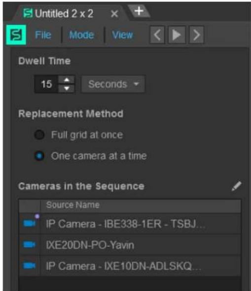
text_image
Untitled 2 x 2 File Mode View Dwell Time 15 Seconds Replacement Method Full grid at once One camera at a time Cameras in the Sequence Source Name IP Camera - IBE338-1ER - TSBJ... IXE20DN-PO-Yavin IP Camera - IXE10DN-ADLSKQ...- Set the Dwell Time period. This is the length of time that the tab will dwell on cameras before advancing to the next camera(s) in the sequence.
- In the Replacement Method area, click to select the radio button for Full grid at once, or One camera at a time. This determines how many cameras you want to replace at the end of each dwell period. When replacing a single camera at a time, the cameras rotate through the grid, left-to-right, top-to bottom. (The next camera in the sequence moves into the top-left cell; the camera formerly in the top-left cell moves to the right, and so on. The bottom-right cell is bumped off the grid, until it re-enters the sequence.)
- To add cameras to the Live Sequence:
a. To the right of Cameras in the Sequence, click the edit icon (✗) to enter the Edit Mode.
b. Either double-click cameras, or drag cameras into the Cameras in the Sequence box.
-
To delete cameras from the Live Sequence, click the x to the right of the name of the camera to delete in the Cameras in the Sequence box.
-
Click Save.
-
Click the Resume Sequence con ().
Creating an Alarm Sequence Mode
Alarm Sequence mode, indicated by the alarm symbol ( ), allows you to designate cameras that you want to watch only when meaningful events occur, so that you never miss activity relevant to your surveillance operations.
By default, the sequence will any camera-associated events that have been configured to provide a notification for your user account and role. You can refine the sequence to a subset of system cameras and a subset of camera-associated events that you want to watch.
To create an alarm sequence:
- In any tab, click Mode and then click Alarm Sequence.
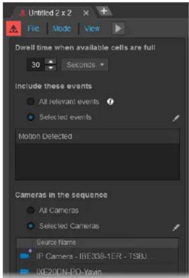
text_image
Untriled 2 x 2 File Mode View Dwell time when available cells are full 30 Seconds Include these events All relevant events Selected events Motion Detected Cameras in the sequence All Cameras Selected Cameras Source Name IP Camera - IBE338-1ER - TSBU... IXE20DN-PO-Yavin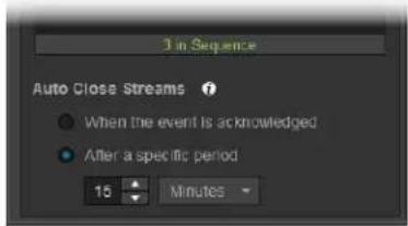
text_image
3 in Sequence Auto Close Streams ? ● When the event is acknowledged ● After a specific period 15 Minutes-
If the Tab Mode Change Confirmation dialog box opens, click OK.
-
Type in a value or select a value using the up and down arrows for Dwell time when available cells are full. This indicates how quickly video rotates through the sequence when you have more current events than available cells in the sequence.
-
(Optional) In the Include these events area, click to select the radio button for Selected Events if you only want to use a subset of events in your sequence, click the Edit icon (☑), click to select or deselect checkboxes for the Event Types to include, and then click Save; otherwise, leave the All relevant events radio button selected.
-
(Optional) In the Cameras in the Sequence area, click to select the radio button for Selected Cameras if you want the sequence to follow a specific subset of cameras, drag cameras into the sequence (the order does not matter for alarm sequences), and then click Save; otherwise, leave the All Cameras radio button selected.
-
(Optional) In the Auto Close Stream area, click to select the radio button for After a specific period, and then enter or select the time period; otherwise, leave the When the event is acknowledged radio button checked.
-
Click the Resume Sequence icon ().
Editing Sequences
Click the Edit icon (✗) to edit the cameras, events, and other settings belonging to a sequence.
You do not need to pause the sequence to edit the cameras in the sequence.
Pausing and Resuming Sequences
Click the Pause Sequence icon (11) to stop cameras from rotating in or out of the sequence. The cameras in the tab will continue to play until you click the Resume Sequence icon (▶).
Setting up Snapshots
You can automatically save snapshots in a folder of your choosing.
- In Mission Control, click the User Menu icon ( ).
- Click Preferences.
- Click General.
- In the When creating snapshots area:
a. Click to select the radio button for JPG or PNG.
b. Click to select or deselect the checkbox for Show overlays on snapshot. If you select this option, also configure the following settings:
- Under Text Size, click to select the radio button for either Use default fixed size or Scale text as a percentage of snapshot height. If you select scaling the text, enter a percentage in the field, either by typing-in a number or selecting one using the up and down arrows.
- Select a Position from the drop-down menu.
- Use the slider bar or type in a value to select the Opacity of Text Background.
- In the Text color area, click to select the radio button for Use default colors or Use white for both camera name and timestamp.
-
Click to select or deselect the checkbox for Auto-save snapshots. If you select this option, enter the folder location to which the snapshots will be saved either by typing in the path or using the Browse button.
-
Click Done to exit the Preferences window.
Taking Snapshots
- Click the Take Snapshot icon (☐) to take a snapshot of the current frame.
-
If you have not set up a location for saved snapshots, provide a location and file name for the snapshot, and then click Save.
-
If you have set up a location for saved snapshots using the instructions in the section titled Setting up Snapshots, the snapshot will be saved to that location without further interaction.
Displaying Statistics
To display camera statistics over live video in the pane, right-click the cell for which you want to see statistics, click Diagnostics, and then click Statistics. Perform this step again to hide the information.
Most statistics presented are self-explanatory; but a few statistics require some explanation:
- Call-up Time is a measure of how long it took between launching a stream and displaying the first frame.
- Pipeline Latency is the amount of buffering used by the client. This directly adds to the end-to-end latency between the camera and the display.
For example: If you have a camera with a 3-second GOP that does not force out iFrames upon new client connections, it might take 3 seconds to call up the first frame, but you could still have very low end-to-end latency thereafter.
Pipeline Latency is independent of Call-up Time.
- Displayed Frame Rate is the average number of frames displayed over a small time period. If frames are dropped by the client, the value could be lower than the camera's configured frame-rate. Because of those differences and because actual frame-rates are rarely whole numbers, the rate is displayed to the second decimal point.
For example: the NTSC standard is 29.7fps, not the 30fps typically shown in a camera configuration UI. If the measured frame-rate is reporting higher than expected, it might be due to a short averaging window. That is, it could be slower or faster at different points in time, but still at the expected average rate over a longer time period.
- Display Jitter is a measure of "jittery" (unsmooth) is the frame presentation. Ideally, frames are displayed smoothly (no jitter) at the exact frame interval of the camera.
For example: Frames from a 30fps source should be displayed at 1/30 second intervals, but if the display is jittery, you will see a noticeable pattern of slow/fast, long/short intervals even though the average frame-rate is still 30.
On many systems, client-side buffering is customer-configurable. Customers can hand-tune the buffering by starting with the smallest value and increasing until visible jitter is minimized.
VideoXpert performs this configuration automatically; streams typically start with a small Pipeline
Latency value, and then the value will increase during the first few seconds of playback to reduce jitter. Entering PTZ input mode forces the latency back to the minimum value, so that PTZ control latency is minimized, potentially at the expense of presentation smoothness.
Measuring Latency

Note: This feature is available to Admin users only. It is used to measure the performance (latency)
of your system using a camera on the system. You must have access to the camera and a monitor to which you can point the camera.
To measure end-to-end latency of the system using any camera:
- Right-click the cell for the camera to view.
- Click Diagnostics, click to select Measure Latency, and then click in the cell.
-
(Optional) Open the same camera in another cell, but do not dislay the Measure Latency view. This helps you better aim the camera at the barcode.
-
Point the camera at the barcode on the VxOpsCenter screen.
When the camera is able to read the barcode, the Scanning Success progress bar (green) begins to fill in.
- Slightly adjust the camera position as needed to get the progress bar to 100%, and then read the Average end-to-end latency measurement above the bar.
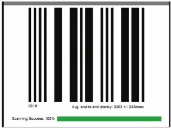
text_image
0618 Avg. end-to-end latency: 0363 +/- 033msec Scanning Success: 100%- To exit the Measure Latency feature:
a. Right-click the cell, click Diagnostics, and then click to deselect Measure Latency.
b. Click the play icon( ) in the cell.
^1 US patent pending, docket number CLO-0186-US-NP/1005700.785US1.
Viewing and Filtering Sources
In Mission Control, click to expand Content, and then click the Sources tab to see a list of all video and audio sources that you are authorized to access.
- Click to expand the Filter area, and use it to shorten the list of sources.
- Enter a Source Name, Model, Number or IP address in the Filter by field.
- In the Advanced Filter Options field, select a filter from the Save and Recall Source List Filter Sets pull-down menu.
- Click to expand Advanced Filter Options to reveal additional options; you can find cameras by Tags, whether they are Online, whether they are Recording, whether they are On Screen, and whether they are equipped with Storage.
When you use two or more tags, the filter will find only those sources that have all of the tags assigned to them.
- To find a filter, click to expand Advanced Filter Options, click Saved Filter Sets, and then click the appropriate filter.
- To save a filter, click to expand Advanced Filter Options, populate the filter, click Saved Filter Sets, and then click Save Filter.
- To toggle between the Folder View and the Video Sources view, click the Show Folder View icon (☐) or the Show List View icon (☐), whichever is visible. These are located at the far right of the window, below the Filter.
See the section titled Managing Tags to create and manage folders.
Managing Tags
The Manage Tags window enables you to see information about a selected camera or cameras, create tags in the system, and organize cameras in a folder structure. Folders behave like tags in that you can use them to filter and search.
To access the Manage Tags window, do one of the following:
- In Mission Control, click the User Menu icon (▼), and then select Manage Tags.
- Right-click a video source, either in a cell or in the Sources list, and then select Manage Tags.
Viewing Tags in the Selected Camera(s) Panel
The Selected Camera(s) panel in the Manage Tags window displays folder tag information. It also allows you to create new tags.
- In Mission Control, in the Content area, in Sources list, select the sources for which to manage tags.
- Access the Manage Tags window.
- Click the Selected Camera(s) tab.
-
Click to select or deselect the checkboxes in the Show field, for My tags, Global tags, and Personal Tags. Not all of these will be present for all cameras.
-
Global tags are signified by the Global icon (☑). These tags are available to all users within the system. All users can filter sources, exports, and bookmarks according to the listed tags.
- Personal tags created by you are indicated by the My Tag icon ( ). These tags are only available to you and administrator-level users. You can use your personal tags to assign and sort resources in a way that best reflects how you use VideoXpert.
-
Folder tags are indicated by the Folder Tag icon ().
-
In the Show tags applicable to selected camera(s), select Any or All.
-
Any shows tags that are assigned to any of the selected cameras.
-
All shows only those tags that are assigned to all of the selected cameras.
-
(Optional) To clear the tag(s) from the selected camera(s), do one of the following:
-
Remove a single tag by clicking the x at the right of the tag itself.
-
Remove all tags by clicking Remove All, and then click Clear in the confirmation dialog box.
-
Click Done to exit the window.
Creating and Assigning Tags in the Selected Camera(s) Panel
You create tags while assigning them. It is important to have a strategy for tags and camera organization before you begin creating and assigning tags.
- Click to select one or more cameras for which to create and apply a tag.
- Access the Manage Tags window.
-
Click within the tag field and type the name of the tag you want to assign; if the tag exists, you can select it and it will autofill.
-
If the tag does not exist, do one of the following:
-
Click Create this tag (personal) to create a tag that is private to your user account.
-
Click Create this tag (global) to create a tag that other users can see and use.
-
Click Done to exit the window.
Deleting Tags in the System Panel
Through OpsCenter, users with sufficient rights can delete global tags.
- Access the Manage Tags window.
- Select the System tab.
- (Optional) Click to select the checkboxes in the Show field to enable or disable My tags, Global tags, or Personal tags.
In addition to the tags included in the Selected Camera(s) panel, you will also see Personal tags which are indicated by the personal tag icon ( ).These tags are only visible to the creator and to administrator-level users. For this reason, there might not be any Personal Tags.
-
Do one of the following:
-
Select the tag you want to delete, and then click the Delete icon (☐).
-
Right-click the tag you want to delete, and then click Delete.
-
In the confirmation dialog box, click Delete.
-
Click Done to exit the window.
Creating Folders in the Folders Panel
A folder is a tag that enables you to group other tags to view in a directory-like structure; you can filter and search using a folder, as you would any other tag.
- Access the Manage Tags window.
- Access the Create New Folder dialog box by doing one of the following:
- Click the Folders tab, right-click in the Folder View area, and then click Add.
- Click the Folders tab, and then in the Folder View area, click the Add New folder icon (+).
- In the Create New Folder dialog box, enter a folder name in the Name field.
- In the Create as field, click to select either the Top-level folder or Child of radio box. If you select Child of, use the drop-down menu to select the appropriate parent folder.
- Click OK.
- In the Drag Cameras To and From Folders area:
a. (Optional) Use the filter to find the appropriate camera(s).
b. Click and drag the camera(s) to the new folder.
A camera can be assigned to only one folder at a time.
-
To remove a camera from the folder, do one of the following:
-
Click and drag it to the Drag Cameras To and From Folders area.
- Click to select the camera, click the Delete icon (☐), and then click OK.
• Right-click the camera, click Delete, and then click OK.
- To assign a camera to a different folder, click and drag it to the appropriate folder in the Folder View area.
- Click Done to exit the window.
Renaming a Folder in the Folders Panel
- Access the Manage Tags window.
- Click the Folders tab.
-
To rename a folder, do one of the following:
-
Right-click the existing folder, click Edit. In the Edit Folder dialog box, enter a new value in the Name field, and then click Save.
-
Click to select the existing folder, click the Edit icon (✗). In the Edit Folder dialog box, enter a new value in the Name field, and then click Save.
-
Click Done to exit the window.
Deleting a Folder in the Folders Panel
- Access the Manage Tags window.
- Click the Folders tab.
-
To delete a folder, do one of the following:
-
Right-click the existing folder, click Delete, and then, in the Delete Folder? dialog box, click OK.
-
Click to select the existing folder, click the Delete icon (☐), and then, in the Delete Folder? dialog box, click OK.
-
Click Done to exit the window.
Playback Controls
Playback controls appear when you hover over a cell containing recorded video.
Table 5: Playback controls (from left to right)
| Icon | Description |
| Click (when white) to activate or (when yellow) to deactivate synchronous play for a cell; select in all cells that you want to synchronize within a tab. | |
| Add a bookmark. | |
| Take a snapshot of the current frame. | |
| Enter investigation mode for all selected cells. | |
| Mute or unmute audio on a source. If there is no audio for the source, the icon is not shown. |
| Icon | Description |
| Rewind video. Click again to increase speeds from 2x, 4x, 8x, 16x, 32x, 64 128x. | |
| Play video at normal speed. | |
| Fast-forward video. Click again to increase speeds from 2x, 4x, 8x, 16x, 32 128x. | |
| Rewind video 30 seconds and initiate playback. | |
| Select the date and time of video you want to watch. | |
| Forward video to live playback. | |
| View video in full-screen or exit the full-screen and return to the tab view. |
Controlling Cameras (PTZ)
Engaging PTZ control changes the color of the border around the cell containing the source (camera) you want to control: blue indicates native PTZ control, and purple indicates digital PTZ mode.
• PTZ mode functions when PTZ cameras are operating in live mode.
• Digital PTZ engages when you:
- Engage PTZ controls for cameras.
- Attempt to place PTZ cameras in playback mode; return to live video to engage native mode for supported cameras.
- Press Alt+Enter to force digital PTZ mode.
In Digital PTZ mode, all PTZ controls affect their digital equivalents. Pan or tilt commands to a camera in digital PTZ mode cause the camera to digitally zoom in the requested direction (as opposed to physically moving the camera's field of view). Zoom commands will digitally zoom the camera from the center of the field of view. Digital PTZ enhancements may affect video quality.
Table 6: PTZ mode icons
| Icon | Description |
| If present, activates Linked PTZ. (PelcoCamera Link) | |
| If present, deactivates Linked PTZ. (PelcoCamera Link) | |
| Locks or unlocks PTZ controls for other users. If present, this icon is located in the cell | |
| The Zoom In icon is located in the cell heading. | |
| The Zoom Out icon is located in the cell heading. | |
| If present, the Cell Layout Menu Options icon is located in the cell heading, to the right of the Zoom In and Zoom Out icons. When you click the icon, you can then click to select Panoramic, Immersive, or Panomersive views.If present the system connection icon is located in the cell heading, to the left of the IP address and/or date and time. When present, the icon indicates that your connection to the system is configured to allow only MJPEG video. | |
| In the cell video, this icon engages the click-to-center mode.Click to center video.Double-click to center video and zoom in. |
- Select the cell you want to control.
-
Engage PTZ controls by one of the following methods:
-
In the upper left corner of the cell, click the Activate Digital PTZ Mode icon (✗ or 📋) or the Activate PTZ Mode icon ( ), whichever is present.
- Press Alt+Enter to force digital PTZ mode, or enter PTZ mode when standard PTZ controls are unavailable.
The cell border will turn blue or purple depending on the PTZ mode supported by the source.
-
Control the camera by one of the following methods. Use the joystick or mouse to affect broad motions, and the keyboard to perform more precise movements.
-
Move the joystick up and down to tilt the camera; press the up and down arrows to nudge the camera vertically.
- Move the joystick left and right or press to pan the camera; press the left and right arrows to nudge the camera laterally.
- Twist the joystick right to zoom in and left to zoom out; press + or Page Up to zoom in and - or Page Down to zoom out. When zooming the camera in, video may jump briefly when the camera switches from physical to digital zoom; to prevent this behavior, disable the camera's digital zoom feature.
-
Use the mouse to pan and zoom. Click on the region to which you want to pan, and double-click to zoom in to the region.
-
To exit PTZ mode, click the Deactivate Digital PTZ Mode icon (or) or the Deactivate PTZ Mode icon ( ), whichever is present.
Using Click-to-Center PTZ
When PTZ mode is enabled, you can click within the cell to center a camera's field of on any point on which you click, within the cell. Click-to-center functionality is not supported for all cameras.
When PTZ mode is enabled within a cell:
- Click in the cell to center the camera's field of view on the location that you clicked.
- Double-click to center video and zoom in on the location that you clicked.
- Hold Alt and double-click, to zoom out.
Using PTZ Zoom to Box
When PTZ mode is enabled, you can draw a box to which the camera will recenter and will zoom in so that the box fills the entire cell that contains the camera stream. Zoom to Box functionality is not supported for all cameras.
When PTZ mode is enabled within a cell:
- Click the Zoom to Box icon (☐) to the right of the PTZ and lock icons.
This icon is only available if the camera supports Zoom to Box.
- In the cell, draw a box to indicate the area to which you will zoom.
To exit the Zoom to Box view, click the Zoom to Box icon again.
Executing PTZ Presets and Patterns
A PTZ preset is a defined PTZ position; you can send the camera to the defined position by calling the preset. A PTZ pattern (or a preset tour) is a series of presets; you can configure most patterns to dwell at each preset for a specific period of time.
If a pattern or preset exists on the camera, to execute it:
- Click the cell in which the camera video is being displayed.
- (Optional) Execute a preset using one of the following methods:
- Right-click the cell displaying the camera, select Presets, and then select the preset you want to execute.
- Click the cell displaying the camera, begin entering the preset number. As you do this, the Quick Launch dialog box opens. When the preset number is displayed in the black box at the center of the Quick Launch dialog box, click the Trigger Preset icon (⊕).
- (Optional) To execute a pattern, right-click, select Pattern, and then select the pattern you want to execute.
- To exit a preset or a pattern:
- To stop a preset or a pattern, click the Deactivate Digital PTZ Mode icon (or) or the Deactivate PTZ Mode icon ( ), whichever is present.
- To stop a pattern only, right-click the cell, select Pattern and then select Stop Pattern.
Creating Presets
VideoXpert does not store presets. Any presets or patterns you create through VxOpsCenter are created and stored camera-side. When you create a preset through VideoXpert, you will assign the preset a numerical value; the preset will appear in the camera or encoder interface as "Preset
If you want to assign a non-numerical, friendly name to a preset, you must change the name of the preset from within the camera interface.

Note: For Pelco NET5500 and NET5400 series encoders, you can edit presets, but you cannot create new ones.
- In the upper left corner of the cell, click the Activate Digital PTZ Mode icon (✗ or ☐) or the Activate PTZ Mode icon ( ), whichever is present.
- Move the camera to the position you want to mark as a preset.
-
Right click, select Preset, and then click Add Preset.
-
Enter or select a number for the preset. The maximum number for the preset is determined by the camera or encoder on which you are creating a preset. Some cameras have reserved values that you cannot use to set a new preset.
- Click OK.
Editing Presets
Some presets are pre-defined by the camera or encoder; you cannot edit these presets.

Note: For Pelco NET5500 and NET5400 series encoders, you can edit presets, but you cannot create or delete presets.
- In the upper left corner of the cell, click the Activate Digital PTZ Mode icon (✗ or 📋) or the Activate PTZ Mode icon ( ), whichever is present.
- Position the camera to the location that you will make the preset.
- Right-click in the cell, click Presets, and then hover over the preset you want to change.
- Click the Reposition the preset to the current PTZ spacial coordinates icon (√).
- Click OK.
Deleting Presets
Some presets are pre-defined by the camera or encoder; you cannot delete these presets.

Note: For Pelco NET5500 and NET5400 series encoders, you can edit presets, but you cannot create or delete presets.
- In the upper left corner of the cell, click the Activate Digital PTZ Mode icon (✗ or ☐) or the Activate PTZ Mode icon ( ), whichever is present.
- Right click in the cell, click Presets, and hover over the preset you want to delete.
- Click the Delete icon ().
- Click Delete.
Using Quick Export
Use Quick Export to export a recording of one or more sources using predefined or custom dates and times.
To use Quick Export from the Sources panel:
- Right-click the source, and then click Quick Export.
- Click to select Previous 5 minutes, Previous Minute, or Custom.
-
If you selected Custom, in the Custom Quick Export dialog box, enter clip start and end dates and times either by typing them in or selecting them from the calendar and/or clock in each field. As you change the dates and times, the export size estimate below the start and end times fields is updated. After you have entered the correct dates and times, click OK.
-
In the Export Playlist As dialog box:
a. (Optional) Enter a new string in the Export Name field.
b. View the export size estimate and verify that you have enough space on the location to which you are exporting the clip.
- The maximum clip size estimate is 11 GB; the size of the clip itself is not limited to 11 GB.
- Playlists with multiple clips will be the estimated sum of the clips.
- The export size estimate does not include VxPlayer. If you are downloading VxPlayer, add the size of the player to the estimate.
c. (Optional) Click to select the checkbox for Export to alternate location. If you select this option:
- Type a valid network path in the Export Location field.
- If necessary, type in a Username and Password in the appropriate fields.
- If appropriate and available, click Copy VxPlayer to This Location.
d. (Optional) If the Encrypt this export is not already selected, and it is appropriate to do so, click to select the checkbox and then type a value in the Password and Confirm Password fields.

Note: If forced export encryption is enabled (in VxToolbox), this option will be selected and grayed-out. All exports are encrypted, unless you export to an alternate location.
e. Click Start Export.
- In the Export Playlist As dialog box, click View Exports to locate the export in the Export Archive, or click Close.
To use Quick Export from a timeline:
- Right-click timeline for a cell or for synchronized cells, and then click Quick Export.
- Click to select Previous 5 minutes, Previous minute, Next minute, Next 5 minutes, or Custom.
- If you selected Custom, in the Custom Quick Export dialog box, enter clip start and end dates and times either by typing them in or selecting them from the calendar and/or clock in each field. As you change the dates and times, the export size estimate below the start and end times fields is updated. After you have entered the correct dates and times, click OK.
- In the Export Playlist As dialog box:
a. (Optional) Enter a new string in the Export Name field.
b. View the export size estimate and verify that you have enough space on the location to which you are exporting the clip.
- The maximum clip size estimate is 11 GB; the size of the clip itself is not limited to 11 GB.
- Playlists with multiple clips will be the estimated sum of the clips.
- The export size estimate does not include VxPlayer. If you are downloading VxPlayer, add the size of the player to the estimate.
c. (Optional) Click to select the checkbox for Export to alternate location. If you select this option:
- Type a valid network path in the Export Location field.
- If necessary, type in a Username and Password in the appropriate fields.
- If appropriate and available, click Copy VxPlayer to This Location.
d. (Optional) If the Encrypt this export is not already selected, and it is appropriate to do so, click to select the checkbox and then type a value in the Password and Confirm Password fields.

Note: If forced export encryption is enabled (in VxToolbox), this option will be selected and grayed-out. All exports are encrypted, unless you export to an alternate location.
e. Click Start Export.
- In the Export Playlist As dialog box, click View Exports to locate the export in the Export Archive, or click Close.
Using Investigation Mode
Investigation mode provides a more detailed interface for synchronized playback and video search in a single window, making it easier to investigate a scene. From investigation mode, users can also trim and export video clips from the system's network video recorder for evidentiary safe keeping.
As you add cameras to the investigation window, the cameras appear in a detailed timeline at the bottom of the tab populated with recording information for each camera. You can use the timeline to navigate the composite recording.
In the timeline:
- A green bar above the recording indicates continuous recording.
- A blue bar above the recording indicates a motion detection recording.
- A red bar above the recording indicates an alarm or analytics recording.
- A thin purple bar under the video recording bar indicates audio recording.
Entering Investigation Mode
Investigation mode provides robust, synchronized playback controls with any number of cells, allowing users to fully investigate an incident across multiple cameras simultaneously. Investigation mode always opens in a new tab.
- Synchronize the cells you want to investigate. To investigate a single cell, do not synchronize any cells; if there cells are already synchronized, then apply Sync to only the cell that you want to investigate.
- Click in a cell in the Sync group, and then click the Investigate icon (☐).
- (Optional) Add cameras to the layout. As you add cameras, they will appear in the cells of the investigation tab, and in the camera list at the bottom of the workspace. A timeline is included in the playback controls area, indicating the availability of recorded video for all cameras.
Using Investigation to View Video Stored on a Camera's Local Storage
If your camera or video source is recording video locally (using an SD card or in concert with ONVIF Profile G), the timeline will display the ; the device tooltip will also alert you to multiple recording locations. You cannot view video while it is stored on the camera; you must first push video from the camera to a VideoXpert Storage recorder in order to view a camera's local recordings.

Note: Refer to documentation for your camera to enable and setup local recording. The process to enable and use local recordings may differ by camera model.
Click to open an investigation tab showing the camera's various recording locations as separate timelines. On VideoXpert Professional systems, the timelines are labeled as follows:
- Default Recorder: Video recorded by your VideoXpert Storage recorder. These are the recordings you would normally see when you playback video.
- Downloaded from Camera: Video pushed from the camera to the recorder does not overwrite video already stored on the recorder; the video recorded on the camera and the video recorded on the VXS recorder coexist. This timeline shows video that has been pushed from the camera to the recorder. You can only view these recordings when in the multi-recording investigation tab.
- Camera Storage: Displays thumbnails representing video stored on the camera. You must use the timeline to create and push video clips to default storage to view it.
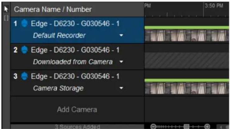
text_image
Camera Name / Number 1 Edge - D6230 - G030546 - 1 Default Recorder 2 Edge - D6230 - G030546 - 1 Downloaded from Camera 3 Edge - D6230 - G030546 - 1 Camera Storage Add Camera 3.Sources AddedPushing Video From the Camera to Storage
This process assumes your camera is recording video locally.
- Click to enter an investigation with timelines representing VideoXpert Storage, the camera's local storage, and video pushed from the camera to the recorder.
- Within the Camera Storage timeline, click and drag along the section of the Camera Storage timeline to indicate the clip or section of video that you want to view.
- Click on the clip to expose the down arrow symbol (▼), and then select Add to Default Recorder.
- Click OK.
You can now play video that was moved from the camera to storage; it will appear in the Downloaded from Camera timeline.
Playing Back Video After Moving it to Storage
Video that has been copied from the camera to Storage will appear in the second timeline, title Downloaded from Camera. Select the section of video you want to play from here and play back. Video is synchronized between your default recorder and the Downloaded from Camera timeline.
Using Auto-backfill Recording Gaps
For cameras on your VideoXpert system that have Edge Storage, Auto-backfill Recording Gaps functionality detects when a gap in recording occurs, queries the camera for recordings, and automatically downloads video and audio (if present) to fill the gap.

Note: This feature must be enabled in order to work. It is enabled and disabled in VxToolbox.
When the recording server has been down, either due to a hardware/software fault or for maintenance, there can be a gap in the recording. When the recording server is online again, the VideoXpert system queries the SD card on the camera for missing video. Recordings are retrieved automatically for the down period.
To use this feature:
-
Click on the camera timeline to display the camera storage icon ( ), and then click the icon to open an investigation tab showing separate timelines for the camera:
-
Default Recorder—on VxStorage only
- Downloaded from Camera—on the camera (Edge Recording)
-
Camera Storage—on the camera's SD card
-
If necessary, add cameras of interest to the investigation.
When you add a camera to an investigation by dragging and dropping from the Source panel in Mission Control, the All Recordings option is selected by default.
- For the appropriate timeline listed in the Camera Name / Number list, click the down arrow icon (▼) to access the drop-down menu, and then click All Recordings.
Creating Clips
Operators can create clips of recorded information, trim video clips, save them to a playlist for safekeeping, or delete them.
The trim tool enables users to select a portion of a recording and save it to a within an investigation as a clip. Clip selections persist in the timeline, even if you choose not to add the clip to the playlist. Once you've selected a clip, you can resize or delete the selection using the time-box controls on the timeline.
- When in Investigation Mode, click on the timeline where you want to select a clip.
- Drag to select the start and end time of the clip you want to add to a playlist.
- To add a clip to a playlist, click on the clip you want to select to expose the down arrow symbol ( ), and then select Add to Playlist.
- To delete a clip, click on the clip to expose the down arrow symbol (▼), and select Delete.
- When you delete the clip, it will be removed from any playlists that you have not exported.
- If you have changed a clip, but would like to undo the change, click on the clip to expose the down arrow symbol ☐), and then select Revert Changes.
Creating a Playlist
A playlist is a series of recorded clips. Operators can trim video clips and save them to a playlist for safekeeping. Playlists are saved locally. You can reference your playlist later, but if you absolutely want to be sure that you don't lose the clips or video in your investigation playlist, you should export the playlist to your Core server.
- When in Investigation Mode, click the selection arrow ( ) above the clip symbol.
- On the timeline, click on the clip to expose the down arrow symbol (▼), and select Add to Playlist. Repeat as necessary.
- Refer to the following sections to preview, edit, or export the playlist.
Previewing and Editing Playlists
- You can preview your playlist at anytime to ensure that it adequately captures your investigation. If it does not, you can reorganize the clips in the playlist or re-trim clips to refine the action captured by each clip.
-
Click and drag clips in the playlist to reorder them.
-
Click the playlist tools icon (💡), and then click Preview Playlist to playback your playlist. Clips are stitched together in the order that they appear in the playlist.
-
Re-trim a clip by either of the following methods:
-
In the playlist, right-click a clip, select Re-trim clip, and then adjust the start and/or end times of the clip. Click Apply when complete to save your changes back to the clip and playlist.
- In the playlist, click to select a clip, click the playlist tools icon (💡), click Re-trim clip, and then adjust the start and/or end times of the clip. Click Apply when complete to save your changes back to the clip and playlist.
- In the timeline, click and drag the start time and/or end time of the clip, click the down arrow symbol (☐), and then select Apply To Playlist. This updates the listing that is already in the playlist.
- Delete a clip from the playlist and from the timeline by one of the following methods:
- In the playlist, click to select one or more clips, right-click one of the selected clips, and then click Delete selected clips.
- In the playlist, click to select one or more clips, click the playlist icon (), and then click Delete selected clips.
- In the timeline, click on a clip to expose the down arrow symbol (▼), and then select Delete.
Exporting a Playlist
Exporting a playlist allows you to save a collection of video clips, so that you can easily find and download your investigation later. Exporting video from network storage to your Core allows you to store video independently of your VideoXpert recorder for quick access later. The system exports unencrypted files in the MKV format, and encrypted files in ZIP format.
If you do not have permission to export video for the video sources in your investigation video, or the recordings saved to your playlist are no longer available from network storage, you will not be able to export a full playlist. You can still export a playlist with missing clips.
If you are logged in as an administrator or have been granted the necessary permissions, you can export a playlist to an alternate location, such as a USB thumb drive or network share. You can view the export in the Export Archive window, but you cannot download the export from the Export Archive window.
You must have created a playlist and be in the investigation mode to export a playlist.
- At the upper right corner of the playlist (left) panel, click the Export Playlist icon (→).
- In the Export Playlist As dialog box, enter a value in the Export Name field.
-
(Optional) Click to select the checkbox for Export to alternate location. If you select this option:
-
Type a valid network path in the Export Location field.
- If necessary, type in a Username and Password in the appropriate fields.
-
If appropriate and the available, click Copy VxPlayer to This Location.
-
(Optional) If the Encrypt this export is not already selected, and it is appropriate to do so, click to select the checkbox and then type a value in the Password and Confirm Password fields.

Note: If forced export encryption is enabled (in VxToolbox), this option will be selected and grayed-out. All exports are encrypted, unless you export to an alternate location.
-
Click Start Export.
-
(Optional) Click View Exports to view the status of your export and view the Export Archive window.
- (Optional) When your export is complete, you can download it locally:
a. In the Export Playlist As dialog box, click View Exports.
b. In the entry for the export, click Download.
c. Navigate to the folder in which you want to save the export; enter a new value in the File name field, or accept the default; and then click Save.
d. (Optional) After the file is saved, click Show File to open the file location, and then open the file.
- At any time, you can view, edit, download, and delete exports from the Export Archive. See the section titled Using the Export Archive.
Encrypting Export Files
When you export a playlist, the VxOpsCenter gives you the option to encrypt the file. Encrypting the file ensures that no one can tamper with your exported video. To decrypt and playback an export, you must have the password used when generating the export and the VideoXport Player; you cannot playback encrypted exports with another video player.
Encrypted exports appear as ZIP archives containing the playlist file, video clips (MKV) and a signature file. When you attempt to open an encrypted export, it will prompt you for the password. The password will allow the player to decrypt the export. The player will then use the signature file and public key (within the signature) to validate the export and verify that it has not been tampered with. It will then playback the file.
If you lose or forget the password to an export, your administrator can recover it for you by returning to the export archive and selecting the export for which you need a password.

Note: If forced export encryption is enabled (in VxToolbox), all exports will be encrypted unless they are exported to an alternate location.
Using the Export Archive
From the Export Archive window, you can download, edit the name of, or delete exports. to access the window:
- If you are still in the Export Playlist As dialog box, click View Exports.
- In Mission Control, click the User Menu icon (▼), and then select Show Export Archive.
Previewing Exports
You can preview exports without downloading them from the Export Archive, which appears automatically when you export a playlist. You can also access the Export Archive at any time. See the section titled Using the Export Archive.
Unencrypted exports use the MKV format. Encrypted exports are ZIP files; if the export file has been encrypted, you must use the VideoXpert Player to decrypt and playback the file.
To preview the export
- Access the Export Archive.
- (Optional) Use the filters or sort the list of available exports by camera tag or other data associated with the export (camera name, ID, exporting user, etc).
- To preview the archive:
a. In the right column (untitled), to the right of Download, click the Export Archive Menu icon (▼).
b. Click Stream Export.
The export opens in a new window. Exports that are not still in storage might take a few minutes to access.
Downloading Exports
You can download exports from the Export Archive, which appears automatically when you export a playlist. You can also access the Export Archive at any time. See the section titled Using the Export Archive.

Note: If you are using VxOpsCenter on a VxPro server, you do not need to download exports; you can browse to the exports directory on your data drive to access exports.
Unencrypted exports use the MKV format. Encrypted exports are ZIP files; if the export file has been encrypted, you must use the VideoXpert Player to decrypt and playback the file.
- Access the Export Archive.
- (Optional) Use the filters or sort the list of available exports by camera tag or other data associated with the export (camera name, ID, exporting user, etc).
- To download the archive without VideoXpert Player:
a. Click Download for the archive row.
b. Browse to a location and type a value in the File name field.
c. Click Save.
d. (Optional) When the archive has been downloaded, click Show File to open the browser to the file location.
- To download the archive and the VideoXpert Player executable:
a. In the right column (untitled), to the right of Download, click the Export Archive Menu icon (▼).
b. Click Download with VideoXpert Player.
c. Browse to a location and type a value in the File name field.
d. Click Save.
e. (Optional) When the archive has been downloaded, click Show File to open the browser to the file location.
Getting the Password for an Encrypted Export
- To access the Export Archive, click the User Menu icon (▼) in mission control, and then select Show Export Archive.
- (Optional) Use the filters to sort the list of available exports by camera tag or other data associated with the export (camera name, ID, exporting user, etc).
- In the right column (untitled), to the right of Download, click the Export Archive Menu icon (▼)
- Click Get Password.
- In the Test Export dialog box, click Copy to Clipboard. The dialog box closes, and you can paste the password to another location.
Editing an Export Name
- To access the Export Archive, click the User Menu icon (▼) in mission control, and then select Show Export Archive.
- (Optional) Use the filters to sort the list of available exports by camera tag or other data associated with the export (camera name, ID, exporting user, etc).
- Click the pencil ico( ) in the left column for the archive row.
- In the Edit Export Name dialog box, type a value in the New Name field.
- Click Save.
Deleting One or More Exports
Deleting an export from the Export Archive sends it to the Trash Bin; you must delete an export from the Trash Bin to permanently remove it from the system. This two-step process prevents users from inadvertently removing exported files from the system.
- To access the Export Archive, click the User Menu icon (▼) in mission control and select Show Export Archive.
- In the Export Archive window, view the list of exports in the table.
• (Optional) Sort by any column title.
- (Optional) Click to expand Filter, type a value in the search field; and/or click in the Camera Tags field, and then click to select the tags. Click Clear in the Camera Tags field to clear the tags, or click Clear Filters at the upper right of the Export Archive window to clear both of the filter fields.
-
(Optional) To delete an export, click the trashcan icon ( ) in the left column for the archive row; in the confirmation dialog box, click to select or deselect the checkbox to Delete Permanently; and then click Yes.
-
If you did not select Delete Permanently, the archive is removed from the current list, and is added to the Export Trash Bin.
-
If you did select Delete Permanently, the archive is deleted, but not added to the Export Trash Bin.
-
(Optional) To delete multiple exports:
a. Click to select the exports to delete (use the Ctrl or Shift keys).
b. Click the trashcan symbol() in one of the selected rows.
c. Click to select or deselect the checkbox to Delete Permanently, and then click Yes.
- If you did not select Delete Permanently, the archive is removed from the current list, and is added to the Export Trash Bin.
- If you did select Delete Permanently, the archive is deleted, but not added to the Export Trash Bin.
-
If you want to view deleted exports, click the down arrow to the right of Export Archive, and then select View Trash Bin.
-
To move an export from the Export Trash Bin to the Export Archive window, click the export Restore button.
- To delete multiple exports from the trash bin, click to select the exports (use Ctrl or Shift), click the Export Archive Menu icon (▼), click Delete Selected Exports, and then click Delete Permanently in the confirmation dialog box.
-
To return to the Export Archive window, click the X symbol in the upper right corner of the Export Trash Bin window.
-
If you want to delete failed exports, click the down arrow to the right of Export Archive, and then click Delete All Failed Exports. In the confirmation dialog box, click to select or deselect the checkbox for Delete Permanently, and then click Yes.
If there are no failed exports, the option will not be present.
- To exit the window, click the X in the upper-right corner of the window, or click outside the window.
Working with Plugins
Plugins are components that enhance the capabilities of VxOpsCenter Client. VxOpsCenter Client supports two types of plugins:
- Overlay plugins provide information supplemental to video and audio sources, and are meant to be used in conjunction with a source; both a source and overlay plugin will populate the same cell.
- Content plugins consume a cell by themselves; adding a content plugin to a cell that is already populated will replace whatever was in the cell.
Installing Plugins
Close the VxOpsCenter application before installing plugins.
To install a plugin, run the plugin installer, typically an MSI file.
Plugins install under C:\ProgramData\Pelco\OpsCenter\Plugins. VxOpsCenter searches this directory recursively on start-up to populate the plugins available to it.

Note: The Access Control System Viewer plugin is not automatically available. Obtain the installer from PartnerFirst.pelco.com, and see the installation instructions in the current version of the VideoXpert™ Installation Manual.
Adding a Plugin to Your Workstation
To add a plugin to your workspace:
- (Optional) Select the cell in which you want to add a plugin.
- Access the available plugins by one of the following methods:
- In Mission Control, click to expand Content, and then click Plugins.
-
In Mission Control, click the Plugins icon ( ).
-
If necessary, click to expand Content Plugins or Overlay Plugins.
-
If the plugin you need is not present in the Plugins panel, install it. See the section titled Installing Plugins.
-
Double-click the plugin to add it to the selected cell (if you selected a cell), or drag the plugin to a different cell. Double clicking a plugin will open the plugin in a manner that is consistent with video sources, as defined by the When double-clicking a source setting, available under Preferences.
-
If a dialog box opens, respond to any prompts.
Installing and Using the BriefCam Plugin™
The BriefCam Plugin ^™ converts unstructured video into structured data that is searchable, actionable, and quantifiable. It performs object tracking and assigns metadata. It enables you to quickly review only video that is relevant, based on the metadata.
To use the BriefCam Plugin:
- Install BriefCam Plugin. To do so, launch the plugin installation wizard, and follow the prompts in the BriefCam Plugin By Pelco Setup window.
- Launch and log in to VxOpsCenter.
-
Click to expand the Content area, click Plugins, and then click BriefCam Plugin by Pelco.
-
In the BriefCam Settings dialog box, enter the appropriate values in the Web Host, Username, and Password fields, and then click Save.
The BriefCam Insights window opens. See the instructions for BriefCam Insights created and maintained by BriefCam.
Using the Event Viewer™ Plugin
The Event Viewer™ plugin allows you to view all events, and filter and sort the events. To use Event Viewer:
- Click Event Log or open the Event Viewer plugin to open the Event Viewer in a cell of the workspace.
-
(Optional) In the Filter (left) panel of the cell, make one or more of the following selections:
-
Click in the Event Source area of the panel, and then click the source from the drop-down menu. Add event sources to the filter, as needed. To remove a source from the list, click the remove icon (✗) to the immediate right of the source name; to remove all sources from the list, click the Clear the current filter settings icon (✗) to the left of Event Source.
- Enter or select a From date, From time, To date, and To time.
- In the Show events with status area, click to select or deselect checkboxes for Needs Attention, In Progress, Acknowledged, and/or No Action Needed.
- (Optional) Enter or select a Range for the Severity of events to display.
- (Optional) Select a User from the drop-down menu. To show only those actions related to the selected user, click to select the checkbox for Only show user related actions.
-
(Optional) In the Type area, select an event category from the drop-down menu, and then select the event type from the drop-down menu below -AND-.
• (Optional) To clear the filter, click Clear. -
(Optional) Click to select the Pause Events checkbox to stop the list from updating. To allow the list to update, click to deselect the checkbox.
- (Optional) To sort, select the criterion from the drop-down menu to the right of Sort by, and then select Ascending or Descending order from the drop-down menu.
- (Optional) If you selected the Needs Attention in the Show events with status field, click Acknowledge Selected at the upper right corner of the Event Viewer to acknowledge all of the events that need attention.
- (Optional) To copy details of an event to paste into another application, right-click the event, click Copy Details, and then click Copy all to clipboard. Navigate to the target application and paste the content.
Using the Image Viewer™ Plugin
The Image Viewer™ Content plugin allows you to display a directory of images within a cell of the Ops Center Client. The images rotate at a designated interval, or you can manually tab through the images. You can use the Image Viewer to scroll through important snapshots from your VxOpsCenter, or to display a series of important images (persons of interest, etc) in the same workspace that you use for video.

Note: The Image Viewer path is stored on the Core, and will follow your account across workstations; if you set a path local to a particular workstation, you will not be able to view your images on another workstation.
- Open the Image Viewer plugin.
- (Optional) Select an existing picture directory containing the images you want to view; this directory can be local or a network location. To do so:
a. Click the menu icon (☐) and then click Select picture directory.
b. Navigate to the folder.
c. Click OK.
- (Optional) If there is no directory, or if you want to save images to a new directory, create one. To do so:
a. Click the menu icon (☐) and then click Select picture directory.
b. Browse to an appropriate location, and then click Make New Folder.
c. Type in a name for the folder, and then click OK.
-
(Optional) To select the speed at which to scroll through the images, click the menu icon (), click Cycle images every..., and then click one of the options.
-
(Optional) Click the menu icon (☐), and then click to select or deselect Show Date/Time.
- (Optional) Click the menu icon (☐), and then click to select or deselect Show Title.
- (Optional) Click the menu icon (☐), and then click to select or deselect Fade between images.
- (Optional) Control scrolling through the images by using the back icon (), the pause icon (), and the forward icon ▶ ) at the lower right of the Image Viewer plugin.
Using the Web Browser Plugin
The Chromium web browser plugin provides a means to access web resources from within VxOpsCenter.
To add the plugin to your workspace:
- Click to expand the Content area, click Plugins, and then drag the Web Browser plugin into a cell.
- You can also double-click Web Browser to open a new single-cell tab containing the plugin.
- Type a value into the search field (a keyword by which to search or a known URL).
- (Optional) To select the whole URL, triple-click in the cell.
Using the Access Control System Viewer Plugin™ (Optional)

Note: This plugin is not automatically available. Obtain the installer from PartnerFirst.pelco.com, and see the installation instructions in the current version of the VideoXpert™ Installation Manual.
The Access Control System Viewer Plugin™ enables the communication and data exchange from various Access Control Systems to the VideoXpert System. A server component, called an Access Control Server, communicates directly to the Access Control System and relays information to the Access Control System Viewer while relaying events between the Access Control System and VideoXpert. While the ACS Server handles events, it also provides other information to the Access Control System Viewer, such as user images that the Access Control System Viewer may display in association with events injected by the ACS Server.
An Access Control Server will provide value without the use of the Access Control System Viewer. Events may be passed to/from the ACS and VX and these events may be viewed with the Event Viewer OCC Plugin or the Admin Portal Events Tab, however, user images, door controls and enhanced Event filters are provided through the Access Control System Viewer Plugin.
Launching the Access Control System Viewer Plugin
- Double-click the plugin or drag and drop it into a cell.
- If an Info dialog box opens, make note of the information, and then click OK to close the box.
Filtering the Events in the Access Control System Viewer
- Click the Filter tab.
- Use the following filter settings to control which events are displayed in the Viewer.
- (Optional) Enter start and end dates and times:
- Select or type in a date and time in the End Time fields--the time before which you want to see filter results.
- Select or type in either the number of Minutes Before to include in the filtered time range OR select or type in a date and time in the Start Time fields.
-
To select a different End Time, click Clear End.
-
In the Show events with status area, click to select or deselect checkboxes for Needs Attention, In-Progress, Acknowledged, and/or Logged.
- (Optional) Select a Property Display Filter from the drop-down menu. This selects what is displayed for an event when it is expanded (center panel). Selecting None displays all properties, selecting Remove IDs displays all properties except those IDs that are unnecessary for the users to see, and Minimal displays only minimal details about the event.
- (Optional) Enter or select a Range for the Severity of events to display.
- (Optional) Select a user from the VMS Users drop-down menu. To show only those actions related to the selected user, click to select the checkbox for Only show user related actions.
- (Optional) In the Events area, select an event category from the drop-down menu, and then select the event type from the drop-down menu below -AND-.
- (Optional) To clear the filter, click Reset Filter.
Configuring Access Control
From the Access Control tab, you can configure communication to an Access Control Server and display information that is not available elsewhere in VideoXpert.
Adding, Editing, and Deleting Access Control Servers
- Click the Access Control tab.
-
If you do not see the Access Control Server list, click the gear icon ⚙️).
-
To add an access control server:
a. Click the Add access control system+ icon ( ).
b. Type a descriptive string in the Server Name field.
c. Type in the IP Address of the server to add.
d. Enter or select the Port number of the server to add.
e. (Optional) Click to select the checkbox for Auto Select Events. When selected, the most recently added event in the event window is automatically selected and expanded.
f. Click Save.
g. (Optional) Repeat this procedure to add another server.
- To edit an existing access control server:
a. Click the Edit access control system icon ( ).
b. (Optional) Type a new descriptive string in the Server Name field.
c. Type in the IP Address of the server to add.
d. Enter or select the Port number of the server to add.
e. (Optional) Click to select the checkbox for Auto Select Events. When selected, the most recently added event in the event window is automatically selected and expanded.
f. Click Save.
-
To delete an access control server, click the Delete access control system icon (☐), and then click Yes.
-
When you have finished configuring the servers, click Close.
Filtering on Access Points
An access point can be anything that the Access Control Server reports as an access point, whether it is a door, gate, or other entryway. All Access Points are listed along with the current known state of the each. The Lock/Unlock button shows the current state and allows the user to toggle Lock/Unlock the door by dragging the button – left for lock, right for unlock. The unlock state appears with a green background.
- Click the Access Control tab.
- Click to expand Access Points.
- Select one or more Access Points from the Access Point list.
- Click to select the checkbox for Add Access Points to Filter.
- In the Event Window, click to select an event that has an access point.
- Only events with that access point ID will be included in the Event Window.
- The associated access point(s) are added to the Access Points list in the Access Control panel.
Filtering on Access Control Users
The Access Control Users section contains a list of known users of the Access Control System. A user may be selected at any time to display their associated image (if available).
- Click the Access Control tab.
- Click to expand Access Control Users.
- From the drop-down menu, click to select an access control user.
- (Optional) Click to select the checkbox for one of the following:
- Add Access Control User to Filter will display only those events that are associated with the selected Access Control User.
- Update User on Event Selection will cause the selected Access Control user to change when an event is selected that has a user associated with it. To choose an event, double-click the event in the Event Window. If you did not deselect the checkbox for Auto Select Events when you configured an Access Control Server, the event will be chosen automatically.
Using the Access Control System Viewer Event Window
The Event Window is the list of events that meet the criteria of the filter and Access Control configuration.
- Click the Access Control tab.
-
Use the following options to find the information you need:
-
(Optional) Click to select or deselect the checkbox to Pause events. Deselect this checkbox to automatically display events as they are received by the VideoXpert System.
- (Optional) In the Sort by field, select Time or Severity from the drop-down menu, and then select Descending or Ascending order from the drop-down menu.
- Click an event to expand it.
- To copy details of an event to the clipboard: click Copy Details, and then click Copy all to clipboard. You can then paste the information into another application.
- View video associated with the event by dragging the view icon ( ) to a cell.
Using the VideoXpert Plates™ ALPR Plugin
The VideoXpert Plates™ ALPR Plugin is a software-based Automatic License Plate Recognition system for video streams. It provides detection and capturing of vehicle license plates, and then compares the captured plates against lists of license plates to provide identification of suspect vehicles, VIPs, parking lot access, authorized vehicles, or unauthorized vehicles; or to identify unknown vehicles.
The plugin is distributed as a compiled binary, and is dependent on the following being present and running:
• Pelco VideoXpert software
• VideoXpert Plates ALPR and VideoXpert Plates Manager applications
To properly install the components of the VideoXpert Plates APLR plugin, follow the instructions in the current version of each of these documents, available on Pelco.com:
• VideoXpert Plates™ Software Installation Manual
• VideoXpert Plates™ Quick Start Guide
• VideoXpert Plates™ ALPR User Manual
• VideoXpert Plates™ Manager User Manual
Understanding VideoXpert Plates ALPR Plugin Architecture
The flow of information between the software components involved in using VideoXpert Plates is shown in the diagram below.
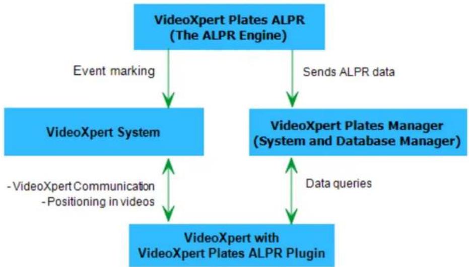
flowchart
graph TD
    A["VideoXpert Plates ALPR (The ALPR Engine)"] -->|Event marking| B["VideoXpert System"]
    A -->|Sends ALPR data| C["VideoXpert Plates Manager (System and Database Manager)"]
    B <-->|-VideoXpert Communication -Positioning in videos| D["VideoXpert with VideoXpert Plates ALPR Plugin"]
    C <-->|Data queries| D
- VideoXpert Plates ALPR recognizes license plates, and then sends information to the VideoXpert Plates Manager. The event (plate capture) is also sent to and marked in the VideoXpert System.
- VideoXpert Plates Manager returns data to VideoXpert Plates ALPR Plugin, based on the search criteria. This accesses the requested VideoXpert video fragment at the timestamp associated with the license plate capture.
- Meta-data is stored and retrieved via the VideoXpert Plates Manager System.
Launching the VideoXpert Plates ALPR Plugin
To begin using the plugin:
- In VxOpsCenter, open VideoXpert Plates Plugin.
- When you first run the plugin:
a. Enter a valid string in the VideoXpert Plates Manager URL field.
- The URL must refer to the location where the VideoXpert Plates Manager service is installed.
- The format will be similar to "http://ipaddress:portnumber/VideoXpertPlates".
b. Enter a valid string in the ApiKey field:
- This is the key used to validate communication with the VideoXpert Plates Manager service.
- Obtain the key in the VideoXpert Plates Manager user interface. Access the Settings menu, and then access the Users window. In the API Key field, copy the key. Paste it into the ApiKey field in the VideoXpert Plates ALPR Plugin. For more information, see the current version of the VideoXpert Plates™ Manager User Manual.
3. Click Login.
A new window opens, showing that VideoXpert Plates Plugin is running.

text_image
Untitled 1 x 1 File Movie View Type: Scan3 Camera Plate From: 14 February 2019 00:00:00 To: Generated an alarm Did not generate an alarm Both Authorized Not authorized Both Search Page 1 Views Content Sciences Plugins Filter Off | Showing it off is search by name View Content Plugins Event Viewer Image Viewer Mapping Web Browser Volatile Overlay Plugins VideoXpert Plates Plugin Bookmarks PELOD VideoXpertIf you see the error message "Error connecting to VideoXpert Plates Manager", it means that communication between the two programs is corrupt. To fix the problem:
-
If you are prompted to enter new credentials, enter the API key as instructed above.
• If you did not receive the prompt, or entering the key did not work: -
Return to VideoXpert Plates Manager.
- Access the Settings menu, and then access the Users window.
- Use the slider Rest API Key, and copy the new key.
- Return to the plugin, stop it, and then restart it by closing the plugin window.
- When prompted, paste the new key into the ApiKey field, and then click Login. A new window opens, showing that VideoXpert Plates Plugin is running.
Searching Plates
After launching the VideoXpert Plates ALPR Plugin, you can search for plates. To do so:
- At the upper left of the plugin window, click the Search tab.
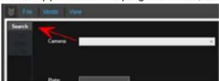
text_image
Search CameraThe Search panel will open. It contains search criteria fields, the Search button, and the plate list area.
- In the Search panel, enter the following search criteria:
a. Use the drop-down menu in the Cameras field so select a specific camera or to click All cameras.
- If you have a dual-camera (Infrared and color environmental camera), and would like to view an image of the plate in color, select the color camera.
- Cameras are available in this field if they have been linked between VideoXpert Plates and VideoXpert, and if they are also active in VideoXpert Plates.
b. Type a partial or complete plate number in the Plate field.
You can use the "?" as a wildcard for a single character, or the "*" as a wildcard for multiple characters. For example: type "?J*" to get a list of all plates in the correct time range that have a "J" as the second character.
c. In the From and To fields, specify a date and time for the search period, either by using the up and down arrows or the calendar.
d. Click to select the appropriate radio button for the Alarm flag. Select Generated an alarm to show only plates that generated an alarm, Did not generate an alarm to show only plates that did not generate an alarm, or Both to show all plates that meet the rest of the search criteria.
e. Click to select the appropriate radio button for the Authorized flag. Select Authorized to show only plates that are allowed in a specific zone, Not authorized to show only plates that are not allowed in a specific zone, or Both to show all plates that meet the rest of the search criteria.
-
Click Search.
-
View the list of plates that match the search criteria in the plate list area. The following information is shown:
-
A list of the plate capture records—Each capture in the list includes the date and time of the capture, the plate number, an image of the plate, and the authorization flag.
- The current page and total number of pages (50 results per page)
- Navigation buttons to move through the pages
-
The total number of records that match the search criteria—If no records matched, you will see the message No records found.
-
(Optional) To display a larger image of the vehicle and plate and to access the video clip associated with the plate read, click the capture in the plate list.
-
Access the video clip by moving the cursor to an appropriate time in the green video timeline beneath the capture image, and then click Play.
- To increase the length of the video that is displayed before the point of capture, see the section titled Configuring User Preferences.
Managing the Black and White Lists
The VideoXpert Plates ALPR plugin includes a List Manager for White and Black lists.
- A Black List is a list of license plates (vehicles) that can cause an alarm to be triggered if the plate is seen. For example, if a company has a list of ex-staff, the security manager might want to receive an email or see an alarm on his screen when any of these vehicles are seen by a camera.
- A White List is a list of license plates that are permitted to enter an area or zone. The system might be set up so that when one of these plates is seen at a camera, a relay device is triggered to open barrier to let them enter the site.
These lists must be initially created in the VideoXpert Plates Manager program. They will then automatically appear here. However, once they have been created, they can be edited from this menu. The user can also add plates to a list, with notes and From and To dates and times during which the lists will be active—when they are allowed in, or when they will trigger an alarm.
To use the Black and White Lists:
- In the upper left corner of the plugin window, click the Lists tab.
- In the List field, click to select a list from the drop-down menu.
- (Optional) Type a partial or complete plate number in the Plate field.
You can use the "?" as a wildcard for a single character, or the "*" as a wildcard for multiple characters. For example: type "?J*" to get a list of all plates in the correct time range that have a "J" as the second character.
- Click Search.
- View the list of plates that match the search criteria in the plate list area. If matches are found, the following information is shown:
• A list of the plate capture records
• The current page and total number of pages (50 results per page)
- Navigation buttons to move through the pages
- The total number of records that match the search criteria—If no records matched, you will see the message No records found.
- (Optional) Click a record to display and/or edit the vehicle details, or to delete the item.
• If you edit the details, click Save changes.
• To delete the item, click Delete item.
- (Optional) To add a vehicle to the list:
a. Click New Item.
b. Enter information into the following fields:
- List name
- Plate number
• Description - Comments
• Active from
• Active to
c. Click Add item.
For more advanced list options, such as importing preexisting lists from .csv files, see the current version of the VideoXpert Plates™ Manager Operations Manual.
Viewing Reads
To veiw plate captures as soon as they are read, click the Reads tab in the upper left corner of the plugin window. The following information is displayed in the panel:
• Capture details, including:
- Time and date
- Camera ID
- Plate number with a plate patch image
- Status (authorized or not)
- List of recently captured plates, with the most recent at the top of the list Click on a plate from the list to display the vehicle image on the right of the screen.
Configuring User Preferences
Each user can configure and save preferences for what to display when a capture is selected/viewed. These preferences are associated with the current user, and will be saved for for the user's next session. To configure preferences:
- In the upper left corner of the plugin window, click the Config tab.
- (Optional) If you will view license plate captures as video, in the Video prebuffer (sec) field, type in a number of seconds that will be included in video before the point of plate capture.
For example: Enter a value of 3 to start the video three seconds before the plate was captured. The default value of zero (0) starts the video at the moment that the plate was captured. - (Optional) If you will view license plate captures as still images, click to select the checkbox for Enable image mode.
Logging Out
To log out of VideoXpert Plates Plugin:
- In the upper left corner of the plugin window, click the Config tab.
- Click Logout.
Closing a Plugin
If you close a plugin without saving your changes, you will lose the changes.
Close a plugin by one of the following methods:
- Click the Ⓧ) icon in the upper right corner of the plugin.
- Click the Close Plugins icon (✗) to the immediate left of the Dock/Undock Mission Control icon at the bottom of the window, and then click the close icon ( ) associated with the plugin you are closing.
Responding to Events
Events in VxOpsCenter are reported in several locations of the UI, depending on how each alarm is configured. Notification methods include:
- The cell that displays the camera for which there is an event will have a flashing red inner border and a red alarm bar at the upper left of the cell.
- In the Content area, in the Sources list, the source item will display with a red background.
• The Event Notifications window enables you to research, snooze, and acknowledge current events. - The Event Viewer lists all events, and allows you to filter and sort the full list of events to include only those that you want to view.
- Recorded alarm events that are triggered by the Rules Engine will show up in the timeline. The color indicates the type of alarm.
Using the Event Viewer
The Event Viewer lists events on the system. To use Event Viewer, see the section titled Using the Event Viewer™ Plugin.
Using the Event Notifications Dialog Box

Note: This section only applies to events that are configured with notifications.
When an event occurs that is pertinent to your user account and has a notification configured, an event notification dialog box will pop-up on your monitor and present ways in which you can respond to the event. Event notifications requiring acknowledgment persist until you or other users with the same role acknowledge them. Other notifications persist based on the configuration of the alarm. See the current version of the VxToolbox section of this manual.
The events icon in the lower-right corner of your workspaces also shows the number of active events that require your attention.
-
Access an event notification by one of the following methods:
-
Click the notification ico(4) at the lower right of the window, and then click to select the notification. Click again to close the list of notifications.
- Click Event Log to open the event(s) in the Event Viewer window.
-
If there is more than one notification, click the Expand icon (☐) in the bottom left corner of the event notification window that pops-up on your screen, and then click to select the notification on which to act. Click the icon again, now labeled Collapse, to close the window. The event notification includes the type of event, the severity of the event, the device (for example, the specific camera) on which the event occurred, and the date and time of the event.
-
(Optional) If the alarm is set with snooze enabled, click Snooze to temporarily remove the visual notifications, but have them reappear at the preconfigured interval.
-
(Optional) Click In-Progress to indicate that you are either investigating the event or are in the process of correcting an event condition.
-
Click Acknowledge to indicate that the event is no longer relevant; or that the event condition has been accounted for or corrected. Acknowledging an event clears the event notification.
-
To copy details of an event to the clipboard: click Copy Details, and then click Copy all to clipboard. You can then paste the information into another application.
-
(Optional) If you accessed an event from the event notification pop-up window, you can click Acknowledge Selected, and then click OK in the confirmation dialog box, to clear the selected event from the event notification window.
Logging Out
When you log out, the application saves your desktop configuration, including video stream and plugins.
- In Mission Control, click the User Menu icon ( ).
- Click Log Out.
- In the Log Out confirmation dialog box, click Log Out.
Closing the Application
It is important to close the application gracefully. Attempting to close the application through the start bar or by other means will leave the application processes open, continuing to consume resources.
All plugin processes must be closed before the application itself can close. When you attempt to exit the application, the application will first save and close all plugin applications before it can close. Depending on the number of plugins populating your workspace, this may take a few moments; do not attempt to forcefully close the application while it is shutting down, or you may lose unsaved workspace information or leave plugins and application processes open.
- In Mission Control, click the User Menu icon ( ).
- Click Exit VxOpsCenter.
- In the Exit VxOpsCenter dialog box, click Exit.
Appendix A: Working With Permissions
Permissions define the actions a user can perform within the system. Where necessary, permissions are defined in a parent-child hierarchy; to assign a child permission, you must first define the parent permission.
Some features are not mapped to an obvious permission; in some cases, a feature might require compounding permissions. For example, users may have the "Place Cameras on Map" permission. However, users must also possess the "View Video Sources" permission for cameras they want to place in order to view video thumbnails and verify that they are placing cameras in the right locations on the map. Pay attention to compound or complex cases listed below to ensure that your users have the permissions they require to perform their surveillance roles within VideoXpert.
Understanding Permission Resource Restrictions
Permissions grant access to resources. Some permissions allow all-or-nothing access, using the Allow All Resources setting; some permissions allow you to select the resources to which a user has access using the Allow Selected Resources or Allow All Resources Except Selected settings. Some permissions can Match Parent Resources.
- If available and selected, Match Parent Resources assigns the same resource to the selected permission as is assigned to its parent.
- Allow All Resources indicates that all resources are accessible by the permission. If the permission does not support restrictions, but is an “on/off” permission, it is the only resource option. For example, selecting Allow All Resources for the View Video Sources permission grants a user access to view live video from all video sources within VideoXpert. If that same user was restricted to Allow Selected Resources for the Use PTZ Mode permission, then the user would be able to view video from all cameras but could only initiate PTZ controls for the cameras to which he or she had access.
- Allow Selected Resources indicates that the user can access all selected resources covered by that permission.
- Allow All Resources Except Selected indicates that the user can access all resources covered by that permission except those that are selected.
Using Supervision and Reports Permissions
Supervision and Report permissions provide access to supervisors checking user activities auditing the system. These permissions are not hierarchical.
| Permission Description | |
| Multiview Enables a supervisor | to see users that are viewing a camera in real time. |
| Define PTZ Presets Allows for | the creating of PTZ presets and pattens for cameras. |
| View Private & Public Views | View all private and public shared views/workspaces. |
| Manage Private & Public Views | Allows full access (create, update, and delete) to all private and public shared views/workspaces. |
| Audit User Activity | Allows users to export User Actions reports. |
Using Device Management Permissions
These permissions grant users the ability to edit devices on the devices page, or tags at the system level.
| Permission Description | |
| Manage System Tags Provides the ability to create, edit, delete, and assign System/Public tags. This permission does not apply to personal tags created or assigned through VxOpsCenter; personal tags only appear to the creating user and only the creating user can assign, modify, or delete his or her own personal tags. | |
| Manage Device Licenses Provides the ability to view, add, and update VX device licenses. | |
| Manage I/O Provides full access to add, remove, and update alarm and relay devices. | |
| Manage Cameras & Recorders Provides full access to add, remove, and update camera and devices. | |
| Manage Display Devices Provides full access to add, remove, and update monitor devices. |
Using User Management Permissions
These permissions grant users the ability to manage user account settings.
| Permission Description | |
| Manage User Accounts Grants | the ability to create, update, or delete user accounts. |
| Assign Roles to Users | Grants the ability to assign roles to users. |
| Reset User Passwords | Grants the ability to change the password for the user accoun |
| Manage Roles | Grants the ability to create, delete, and assign permissions to |
Using Event Management Permissions
Event management permissions enable users to view, act on, and configure event notifications. There is no hierarchy for these permissions, but in most cases, a user that can configure events should have access to the event log and be able to handle events.
| Permission Description | |
| View Event History | Allows users to view the event history.Note: This permission does not include user audit events. The "Audit User Activity" permission is needed to view those events. |
| Handle Events | Allows a user to act on event notifications, marking them as "in progress" or acknowledging them.Note: This permission does not guarantee that a user will receive events, only that the users with this permission can act on event notifications the receive. Event notifications are defined within each event; the ability to modify events is granted by the "Configure Events" permission. |
| Configure Events Provides the | ability to configure events. |
Using System Management Permissions
System Management permissions should be reserved for administrators. Users with these permissions can modify system configuration settings; these changes should be carefully planned by administrators to ensure that they do not interfere with video recording or interrupt surveillance operations.
| Permission Description | |
| Manage System Licenses Provides the ability to view, add, and update VideoXpert system licenses. | |
| Set System Locale Options Allows configuration of the VideoXpert System time. | |
| Configure Recording Allows configuration of recording, including recording schedules, camera assignments, and retention periods; this permission does not affect access to the VXS Recorder interface. | |
| View System Health Allows the user to view VideoXpert system diagnostic information, including hardware and network status, temperatures, loads, and recording gaps. | |
| Manage System Servers Provides the ability to edit settings. | |
| Manage Member Systems | Provides the ability to add, edit, and remove aggregated VideoXpert systems. |
Using Surveillance Permissions
Surveillance permissions are common permissions required by operators in your VideoXpert environment. These permissions grant access to view live or recorded video and to control cameras.
| Permission Description | |
| View Video Sources Enables | users to access live video or audio. Audio sources are tied to video sources; granting access to a video source automatically grants access to associated audio sources. |
| Use PTZ Mode | Provides the ability to pan, tilt, and zoom a camera. This permission includes a priority; priority determines who can control a camera in the event of competing users. If two or more users attempt to control a camera, the user with the highest priority will take command and lower priority users will be locked out. |
| Lock PTZ Mode | Provides the ability to lock a camera into a particular PTZ position. PTZ locks may be overridden by users with higher priority than the user who set the lock. |
| Send Video Allows a user to | send video to a remote monitor, rather than all monitors, to monitor walls, and to shared displays. |
| Access Alarms Allows a user | to view system alarm devices. |
| Access Relays Allows a user | to view and activate system relay devices. |
Using Investigation Permissions
Investigation permissions grant access to recorded video and the ability to export video from the system. Typical setups will want to assign the same access level to "view recorded video" permissions as to "view video sources".
| Permission Description | |
| View Recorded Video Enables | users to access live video or audio. Audio sources are presently tied to video sources; granting access to a video source automatically grants access to associated audio sources. |
| Create Exports Allows a user to create exports. | |
| Manage My Exports | Allows a user to edit or delete entries in the “Manage Exports” window. |
| Download My Exports | Allows users to download exports that they have created. |
| Stream My Exports | Allows users to stream exports that they have created. |
| Create Exports in Alternate Locations | Enables users to save exports to locations other than the default. |
| View All Exports | Allows a user to view all users' exports. |
| Manage All Exports | Allows a user to edit or delete all users' exports. |
| Download All Exports | Allows a user to download all users' exports. |
| Stream All Exports | Allows a user to stream all users' exports. |
| Create System Bookmarks | Allows a user to create system bookmarks |
| Lock System Bookmarks | Allows a user to lock system bookmarks. |

a Motorola Solutions Company

Pelco, Inc.
625 W. Alluvial Ave., Fresno, California 93711 United States
(800) 289-9100 Tel
(800) 289-9150 Fax
+1 (559) 292-1981 International Tel
+1 (559) 348-1120 International Fax
www.pelco.com
Pelco, the Pelco logo, and other trademarks associated with Pelco products referred to in this publication are trademarks of Pelco, Inc. or its affiliates. ONVIF and the ONVIF logo are trademarks of ONVIF Inc. All other product names and services are the property of their respective companies. Product specifications and availability are subject to change without notice.
© Copyright 2020, Pelco, Inc. All rights reserved.