Sarix Enhanced IXE33 - Security Camera Pelco - Free user manual and instructions
Find the device manual for free Sarix Enhanced IXE33 Pelco in PDF.


| Product Type | Security Camera (Box IP Camera) |
| Model | Sarix Enhanced IXE33 |
| Resolution | 3 MP |
| Lens Mount | iCS (Intelligent CS-mount) - only iCS lenses compatible |
| Power Supply | 12 VDC, 2A or 24 VAC, 1.5A; PoE (IEEE 802.3af) compliant |
| Network Interface | RJ-45 1000BASE-TX, PoE |
| Storage | Micro SD/SDHC/SDXC slot (up to 256 GB, min write speed 10 MB/s) |
| Alarm/Audio | Alarm input/output, audio input/output via multi-conductor cable |
| Video Compression | H.264 (via Sarix Enhanced Series firmware) |
| Supported Protocols | IPv4, DHCP, HTTP, Web browser access |
| Web Browser Compatibility | Latest Microsoft Edge, Google Chrome, Mozilla Firefox |
| System Integration | Compatible with VideoXpert, VX Toolbox, Endura 2.0+, Digital Sentry 7.3+ |
| Status LED | Solid red (error), flashing green (booting), flashing orange (firmware update), solid amber (cold start) |
| Reset / Defaults | Reset button (reboot); Defaults button (hold 4 sec for factory reset) |
| Operating Temperature | Not specified, typical for indoor/environmental enclosures |
| Dimensions (Body) | Not specified |
| Weight | Not specified |
| Safety / ESD | ESD sensitive; use ESD wrist strap during installation; FCC Class A |
| Maintenance & Cleaning | Use clean compressed air for lens; do not touch imager; avoid dust |
| Warranty | Refer to www.pelco.com/warranty |
| Spare Parts / Repairability | No user-serviceable parts; contact Pelco support for repair |
Frequently Asked Questions - Sarix Enhanced IXE33 Pelco
User questions about Sarix Enhanced IXE33 Pelco
0 question about this device. Answer the ones you know or ask your own.
Ask a new question about this device
Download the instructions for your Security Camera in PDF format for free! Find your manual Sarix Enhanced IXE33 - Pelco and take your electronic device back in hand. On this page are published all the documents necessary for the use of your device. Sarix Enhanced IXE33 by Pelco.
USER MANUAL Sarix Enhanced IXE33 Pelco
Sarix® Enhanced Series III
natural_image
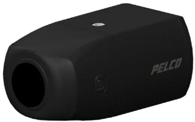
Black Pelco device with hexagonal body and circular opening, no visible text or symbols on bodyBox (IXE) Camera Models
C6659M (3/20)
Contents
Contents....3
Important Notices 5
Regulatory Notices (FCC Class A)....5
Radio and Television Interference 5
Legal Notice (Audio Notice) 5
Video Quality Caution 5
Open Source Software Notice 5
Power Source 6
ESD Warning....6
Warranty Statement 6
Supplemental Resources 6
Firmware Version 6
Description....8
System Model Numbers 8
Recommended Mounts 8
Recommended Lenses 8
Recommended Enclosures 8
Box Camera Models 9
Supplied Parts List 9
User-Supplied Parts List 9
Product Label 9
Getting Started....9
Product Overview....10
Installation....11
Connecting the Cables 12
Ethernet Wiring Requirement for PoE 13
Power Wiring 13
Alarm/Relay/Audio Port 14
Accessing the Camera 14
Pelco Troubleshooting Contact Information 15
REGULATORY NOTICES (FCC CLASS A)
This device complies with Part 15 of the FCC Rules. Operation is subject to the following two conditions: (1) this device may not cause harmful interference, and (2) this device must accept any interference received, including interference that may cause undesired operation.
RADIO AND TELEVISION INTERFERENCE
This equipment has been tested and found to comply with the limits of a Class A digital device, pursuant to Part 15 of the FCC rules. These limits are designed to provide reasonable protection against harmful interference when the equipment is operated in a commercial environment. This equipment generates, uses, and can radiate radio frequency energy and, if not installed and used in accordance with the instruction manual, may cause harmful interference to radio communications. Operation of this equipment in a residential area is likely to cause harmful interference in which case the user will be required to correct the interference at his own expense.
Changes and Modifications not expressly approved by the manufacturer or registrant of this equipment can void your authority to operate this equipment under Federal Communications Commission's rules.
This Class A digital apparatus complies with Canadian ICES-003.
NOTE: Improper use of audio/visual recording equipment may subject you to civil and criminal penalties. Applicable laws regarding the use of such capabilities vary between jurisdictions and may require, among other things, express written consent from the recorded subjects. You are solely responsible for insuring strict compliance with such laws and for strict adherence to any/all right of privacy and personality.
VIDEO QUALITY CAUTION
Frame Rate Notice Regarding User-Selected Options
Pelco systems are capable of providing high quality video for both live viewing and playback. However, the systems can be used in lower quality modes, which can degrade picture quality, to allow for a slower rate of data transfer and to reduce the amount of video data stored. The picture quality can be degraded by either lowering the resolution, reducing the picture rate, or both. A picture degraded by having a reduced resolution may result in an image that is less clear or even indiscernible. A picture degraded by reducing the picture rate has fewer frames per second, which can result in images that appear to jump or move more quickly than normal during playback. Lower frame rates may result in a key event not being recorded by the system.
Judgment as to the suitability of the products for users' purposes is solely the users' responsibility. Users shall determine the suitability of the products for their own intended application, picture rate and picture quality. In the event users intend to use the video for evidentiary purposes in a judicial proceeding or otherwise, users should consult with their attorney regarding any particular requirements for such use.
OPEN SOURCE SOFTWARE NOTICE
This product includes certain open source or other software originated from third parties that is subject to the GNU General Public License (GPL), GNU Library/Lesser General Public License (LGPL) and different and/or additional copyright licenses, disclaimers, and notices.
The exact terms of GPL, LGPL, and some other licenses are provided to you with this product. Please refer to the exact terms of the GPL and LGPL at http://www.fsf.org (Free Software Foundation) or http://www.opensource.org (Open Source Initiative) regarding your rights under said license. You may obtain a complete corresponding machine-readable copy of the source code of such software under the GPL or LGPL by sending your request to digitalsupport@pelco.com; the subject line should read Source Code Request. You will then receive an email with a link for you to download the source code.
This offer is valid for a period of three (3) years from the date of the distribution of this product by Pelco.
POWER SOURCE
This product is intended to be supplied by a Listed Power Adapter or DC power source marked Class 2 or L.P.S. (or "Limited Power Source"), rated 12Vdc, 2A, or 24Vac (50/60 Hz), 1.5A. When used with Power over Ethernet (PoE), the Power Sourcing Equipment (PSE) shall comply with IEEE802.3af and Limited Power Source (LPS) according to clause 2.5 of IEC/EN/UL 60950-1 or annex Q of IEC/EN/UL62368-1.
KOREAN CLASS A EMC
WARNING: This product is sensitive to Electrostatic Discharge (ESD). To avoid ESD damage to this product, use ESD safe practices during installation. Before touching, adjusting or handling this product, correctly attach an ESD wrist strap to your wrist and appropriately discharge your body and tools. For more information about ESD control and safe handling practices of electronics, please refer to ANSI/ESD S20.20-1999 or contact the Electrostatic Discharge. Association (www.esda.org).
WARRANTY STATEMENT
For information about Pelco's product warranty and thereto related information, refer to www.pelco.com/warranty.
SUPPLEMENTAL RESOURCES
All resources are available in one location: https://www.pelco.com/fixed-ip-sarix-enhanced-series From this location, select the asset(s) you want to download.
Name Description
Sarix Enhanced Series Firmware Download the latest firmware for your Sarix Enhanced Series camera system. Sarix Enhanced Series Documentation Download the latest specification sheets as well as installation and operations manuals for the Sarix Enhanced Series.
VxToolbox Download the latest firmware for camera management utility. This software helps you discover the camera and update firmware.
FIRMWARE VERSION
Before installing the camera, visit the online Pelco supplemental resources to check for firmware updates.
Description
The Sarix Enhanced III Series Box cameras are compatible with a choice of standard iCS (Intelligent CS-mount) megapixel lenses for wide angle or long range surveillance needs.
The Sarix Enhanced III Series Box camera offers flexible mounting options, and uses a standard Web browser for easy remote setup and administration. The Sarix Enhanced III Series Box camera easily connects to Pelco IP and hybrid systems such as VideoXpert, VX Toolbox, Endura version 2.0 (or later), and Digital Sentry version 7.3 (or later).
This document describes the installation and initial setup procedures to begin operating the camera. For more information about operating your camera, refer to the operation manual specific to the product.
SYSTEM MODEL NUMBERS
| Resolution Model Number Description | ||
| 2 MP IXE23 | 2 MP Sarix Enhanced Box IP Camera | |
| 3 MP IXE33 | 3 MP Sarix Enhanced Box IP Camera | |
| 5 MP IXE53 | 5 MP Sarix Enhanced Box IP Camera | |
| 8 MP IXE83 | 4 K Sarix Enhanced Box IP Camera | |
RECOMMENDED MOUNTS
| Mounts Description | |
| C11-UM Gang box mount | |
| CM1750 Pedestal mount | |
| TB1751 T-rail mount | |
RECOMMENDED LENSES
| Lens Description | |
| MI2.8-8.5P* MP iCS lens | 2.8-8.5 mm |
| MI3.9-10P MP iCS lens 3 | 9-10 mm |
| MI9-50P MP iCS lens 9-50 | mm |
*Compatible with IXE23 and IXE33 only.
RECOMMENDED ENCLOSURES
| Enclosure Description | |
| EH20 Series Indoor and environmental enclosures | |
| EHS8000 Series Indoor and environmental enclosures |
BOX CAMERA MODELS
SUPPLIED PARTS LIST
Qty Description
1 Camera
1 Installation manual
1 Important Safety Instructions document
1 China RoHS document
USER-SUPPLIED PARTS LIST
In addition to the standard tools and cables required for a video security installation, you will need to provide the following items:
Qty Description
1 iCS megapixel lens
1 Up to 256 GB Micro SDHC or SDXC card capable of a minimum write speed of 10 MB/sec is recommended for recording HD video (optional)
1 RJ-45 connector to terminate cable
1 Cat5e (or higher) cable
1 Mounting hardware (refer to Optional Accessories section)
1 24-28 AWG 4, 8, or 10 multi conductor cable for alarms and/or audio and/or power (optional)
1 16-20 AWG 2 conductor cable for power (optional)
PRODUCT LABEL
The product label lists the model number, serial number, and Media Access Control (MAC) address. This information might be required for setup. A product label is located on the bottom of the camera and on the side of the product box.
GETTING STARTED
Before installing your device, thoroughly familiarize yourself with the information in the installation section of this manual.
NOTES:
- Pelco recommends connecting the device to a network that uses a Dynamic Host Configuration Protocol (DHCP) server to address devices.
- Do not use a network hub when configuring the network settings for the device.
- To ensure secure access, place the device behind a firewall when it is connected to a network.
text_image
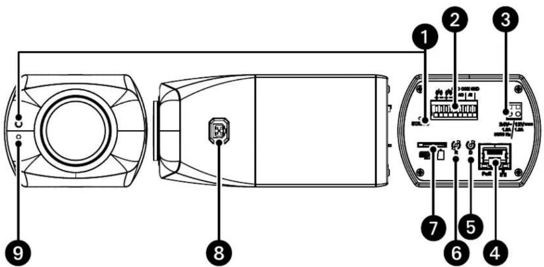
Diagram of a device rear panel with labeled components and internal wiring, showing connections between ports and connectors.Figure 1. Sarix Enhanced III IXE Series Box
1. Status LED Indicators:
a. Solid red for more than 5 seconds indicates there is a booting error. Flashing green indicates booting is normal.
b. Flashing orange indicates a firmware update is in progress.
c. LED will turn off after a successful boot up.
d. Solid amber indicates the camera is in a cold start state (warming up before fully booting).
- Alarm/Relay/Audio Port: Connects to alarms, relays, and audio in/out.
- Power Connector: A two-pin connector for 12 VDC or 24 VAC.
- RJ-45 Network Port: Connects the camera to the IP network. Also supplies power to the camera (POE), through the same connector. (NOTE: To purchase a power supply, please contact Pelco for further information.)
a. Green LED: With solid green, the LED indicates a live connection is established.
b. Orange LED: With flashing orange, the LED indicates data is being transmitted/received between camera and switch.
- Defaults Button: Press and hold the button for 4 seconds to restore the camera to factory default settings.
- Reset Button: Cycles power to the camera and initiates a reset. Press and release the reset button once to reboot the camera.
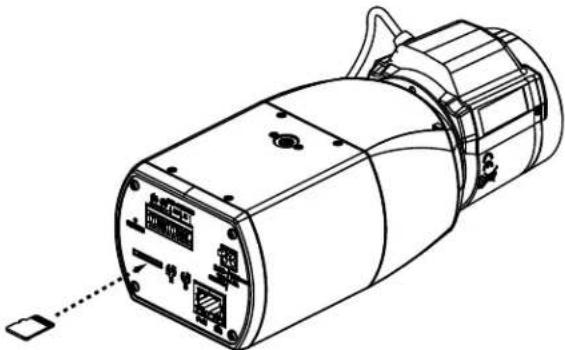
- Micro SD Slot: Install the SD card into the card slot to store videos and snapshots. Do not remove the micro SD card when the camera is powered on.
- iCS Lens Connector: Insert the 5-pin connector from the iCS lens into this connector.
- Microphone: Microphone for capturing sound.
NOTE: Pelco megapixel (MP) iCS lenses have been designed and tested to deliver optimal image quality for the IXE Series box camera. This camera only accepts iCS lenses. Using a non-iCS lens may damage the camera. Please contact Pelco for more information.
- Install the iCS lens.
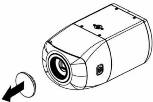
a. Remove the outer cover from the lens mount.
natural_image
Line drawing of a cylindrical device with a circular button and directional arrow (no text or symbols)Figure 2. Remove the Cover from the Lens Mount
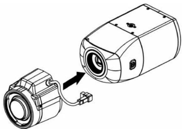
b. Tighten the iCS lens onto the lens mount. Be careful to prevent dust from entering the space between the iCS lens and the imager. If necessary, use clean, compressed air to remove any foreign matter (refer to the instructions shipped with the iCS lens). Make sure the lens does not touch the camera imager when installed.
natural_image
Technical line drawing of a camera module with an attached cable, showing no text or symbolsFigure 3. Tighten the iCS Lens Onto the Lens Mount
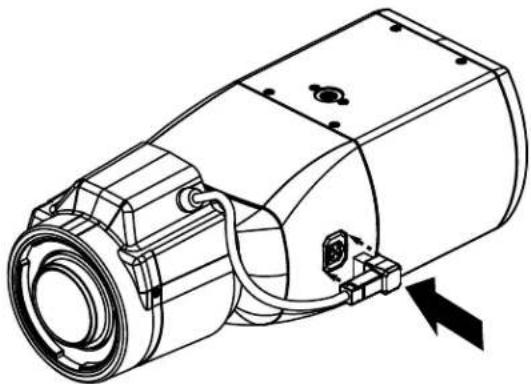
c. Connect the iCS lens cable to the 5-pin connector located on the side of the camera.
natural_image
Technical line drawing of a mechanical device with no visible text or symbolsFigure 4. Connect the iCS Lens Cable to the Connector
d. (Optional) Insert a Micro SD Card into the slot. NOTE: Do not remove the microSD card when the camera is powered on.
natural_image
Technical line drawing of a cylindrical device with internal components and a dotted connection line (no text or symbols)Figure 5. Insert a Micro SD Card
-
Install the camera on the mount in the desired location (refer to the installation/operations manual for the recommended mount). The camera can be attached to the mount from either the top or bottom threaded 1/4-20 threaded mounting hole, depending on the type of camera mount used in your installation.
-
Connect the cables to the camera. Refer to the Connecting the Cables section for wiring instructions and the Product Overview for connector port locations.
-
Apply power to the camera. The camera will complete a configuration sequence. The Status LED Indicators located on the front and back can be used to identify the stage the camera is at in it's configuration.
-
Refer to Accessing the Camera section to view the camera image.
-
the camera field of view is set by adjusting zoom and focus via the Web UI. Refer to the operations manual.
CONNECTING THE CABLES
The I/O interfaces appear on the back of the camera module (Refer to Figure 1). Make the appropriate connections.
ETHERNET WIRING REQUIREMENT FOR POE
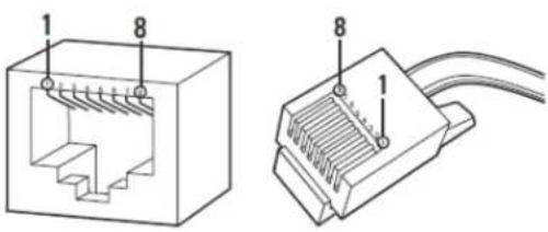
Connect a Cat5e cable or higher cable (not supplied) to the RJ-45 network connector. The 8-pin port includes video over Ethernet, and PoE for the camera. PoE injects power over the same cabling that carries the network data, eliminating the need for a separate power supply. This simplifies the installation and operation of the camera without affecting network performance.
Figure 6. Pin Numbering
text_image
Technical diagram of a Ethernet connector showing internal structure and cable connection detailsFigure 7. Pin Functions
| 1000BASE-TX | ||||||
| Pin Function | ||||||
| 1 | B | I | - | D | A | + |
| 2 | B | I | - | D | A | - |
| 3 | B | I | - | D | B | + |
| 4 | B | I | - | D | C | + |
| 5 | B | I | - | D | C | - |
| 6 | B | I | - | D | B | - |
| 7 | B | I | - | D | D | + |
| 8 | B | I | - | D | D | - |
POWER WIRING
To wire the connector, use a small slotted screw driver to depress the connector tabs and then insert cables into the power connector. Attach the cables as shown in Figure 1 (e.g. Pin 1 is 12 VDC or 24 VAC 1; Pin 2 is GND or 24 VAC 2).
NOTE: 12 VDC or 24 VAC may be used instead of PoE or in addition to PoE for power failover in case PoE/network is temporarily lost.
ALARM/RELAY/AUDIO PORT
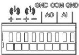
| Designation Function | ||
| Alarm Input | AI Alarm In + | |
| GND Ground | ||
| Alarm Output | GND Ground | |
| AO Alarm Out + | ||
| COM Common | ||
| Audio In | (x336) | Audio In + |
| Audio In - | ||
| Audio Out | (w870) | Audio Out + |
| Audio Out - | ||
Figure 8. Relay and Alarm Connections
text_image
GND COM GND + - + - AO AIFigure 9. Box Pinout Detail
ACCESSING THE CAMERA
Anyone who access the camera can view live video. If you want to prevent users from viewing video without logging in, you must change the permissions for public users.
The recommended browsers for your camera are the latest version of Microsoft™ Edge™, Google Chrome™ browser, or Mozilla® Firefox®. for supported browser versions, refer to the specification sheet.
- Open a web browser.
- Type the camera's IP address (192.168.0.20) or host name in your browser's address bar, and the press Enter.
NOTE: You can obtain your camera's IP address or access the camera using the VxToolbox software. If DHCP is enabled but a DHCP server is not on the network, the camera automatically assigns itself both an IPv4 link local address (169.254.x.x, where the lower two octets are random) and a 192.168.0.20 address. Additional cameras will assign themselves different IPv4 link local addresses and the next available 192.168.0xIP addresses in sequential order. For example, if three cameras are connected to a network without a DHCP server, the first camera to connect assigns itself the IP address 192.168.0.20, the second camera assigns itself 192.168.0.21, and the third camera assigns itself 192.168.0.22.
- Click Login.
- If needed, type your user name and password.
NOTE: For security purposes, it is recommended that you create a user account when you login to the camera for the first time.
- In its out-of-the-box configuration, the camera has no user name and password assigned. For security purposes, it is recommended that you set an administrative user name and password after initial configuration of the camera. Creation of an administrative user name changes the state of the camera to its “operational mode,” where credentials must be provided in order to change its configuration.
- There is no provision for recovering a forgotten administrator user name or password. The camera can be restored to its out-of-the-box, no-password configuration by depressing the Defaults button with an object such as a paper clip, and holding the button down for at least four seconds.
- If a user name and password exist, a Login link appears in the upper right area of your web browser.
5. Click Log In.
PELCO TROUBLESHOOTING CONTACT INFORMATION
If the instructions provided fail to solve your problem, contact Pelco Product Support at 1-800-289-9100 (USA and Canada) or +1-559-292-1981 (international) for assistance. Be sure to have the serial number available when calling.
Do not try to repair the unit yourself. Leave maintenance and repairs to qualified technical personnel only.
PELCO™
Pelco, Inc. 625 W. Alluvial Fresno, California 93711 United States
USA & Canada Tel (800) 289-9100 Fax (800) 289-9150
International Tel +1 (559) 292-1981 Fax +1 (559) 348-1120
www.pelco.com