PT-MA-HDBT42 - Switch PureTools - Free user manual and instructions
Find the device manual for free PT-MA-HDBT42 PureTools in PDF.


User questions about PT-MA-HDBT42 PureTools
0 question about this device. Answer the ones you know or ask your own.
Ask a new question about this device
Download the instructions for your Switch in PDF format for free! Find your manual PT-MA-HDBT42 - PureTools and take your electronic device back in hand. On this page are published all the documents necessary for the use of your device. PT-MA-HDBT42 by PureTools.
USER MANUAL PT-MA-HDBT42 PureTools
text_image
4x2 PowerFactor PowerFactor Auto Auto Auto Auto Auto Auto Auto Auto Auto Auto Auto Auto Auto Auto Auto Auto Auto Auto Auto Auto Auto Auto Auto Auto Auto Auto Auto Auto Auto Auto Auto Auto Auto Auto Auto Auto Auto Auto Auto Auto Auto Auto Auto Auto Auto Auto Auto Auto Auto Auto 0.5V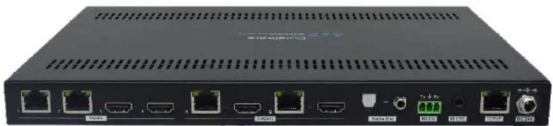
natural_image
Front view of a black network switch device with multiple ports and connectors (no visible text or labels)User Manual
4x2 HDBT Matrix Switcher
Model PT-MA-HDBT42
Designed in Germany
Preface
Read this user manual carefully before using this product. Pictures shown in this manual are for reference only. Different model layouts and specifications are subject to the physical product.
This manual is for operation instructions only, not for any maintenance usage.
In the constant effort to improve our product, we reserve the right to make changes in functions or parameters without prior notice or obligation.
Trademarks
Product model and logo are trademarks. Any other trademarks mentioned in this manual are acknowledged as the properties of the trademark owner. No part of this publication may be copied or reproduced without the prior written consent.
FCC Statement
This equipment generates, uses and can radiate radio frequency energy and, if not installed and used in accordance with the instructions, may cause harmful interference to radio communications. It has been tested and found to comply with the limits for a Class B digital device, pursuant to part 15 of the FCC Rules. These limits are designed to provide reasonable protection against harmful interference in a commercial installation.
Operation of this equipment in a residential area is likely to cause interference, in which case the user at their own expense will be required to take whatever measures may be necessary to correct the interference.
Any changes or modifications not expressly approved by the manufacture would void the user's authority to operate the equipment.
REACH | 1907/2006/EU
ROHS | 2011/65/EU
PureLink hereby declares that this product PureTools PT-MA-HDBT42 complies with Directives 1907/2006/EU und 2011/65/EU.
EMC / LVD (Electro Magnetic Compatibility / Low Voltage Directive)
PureLink GmbH hereby declares that this product PureTools PT-MA-HDBT42 complies with Directives 2014/30/EU and 2014/35/EU. The full text of the EU Declaration of Conformity is available at the following Internet address:
http://www.purelink.de/ce/4251364721476_CE.pdf

SAFETY PRECAUTIONS
To ensure the best from the product, please read all instructions carefully before using the device. Save this manual for further reference.
- Unpack the equipment carefully and save the original box and packing material for possible future shipment
- Follow basic safety precautions to reduce the risk of fire, electrical shock and injury to persons.
- Do not dismantle the housing or modify the module. It may result in electrical shock or burn.
- Using supplies or parts not meeting the products' specifications may cause damage, deterioration or malfunction.
• Refer all servicing to qualified service personnel.
- To prevent fire or shock hazard, do not expose the unit to rain, moisture or install this product near water.
- Do not put any heavy items on the extension cable in case of protrusion.
- Do not remove the housing of the device as opening or removing the housing may expose you to dangerous voltage or other hazards.
- Install the device in a place with sufficient ventilation to avoid damage caused by overheat.
- Keep the module away from liquids.
- Spillage into the housing may result in fire, electrical shock, or equipment damage. If an object or liquid falls or spills on to the housing, unplug the module immediately.
- Do not twist or pull by force ends of the optical cable. It can cause malfunction.
- Do not use liquid or aerosol cleaners to clean this unit. Always unplug the power to the device before cleaning.
- Unplug the power cord when left unused for a long period of time.
- Information on disposal for scrapped devices: do not burn or mix with general household waste, please treat them as normal electrical wastes.
Table of Contents
- Product Introduction .... 1
1.1 Features .... 1
1.2 Package List .... 2
-
Specification....3
-
Panel Description....5
3.1 Front Panel....5
3.2 Rear Panel....6
-
System Connection....7
-
Button Control....8
5.1 Manual Switching 8
5.2 Auto Switching....8
-
IR Remote Control....9
-
GUI Control 10
7.1 Video Tab.... 11
7.2 Audio Tab.... 12
7.3 Configuration Tab....13
7.3.1 PoC Setting.... 13
7.3.2 EDID Setting....14
7.4 CEC Tab 15
7.5 Tag Tab 18
7.6 RS232 Tab 19
7.7 Network Tab....21
7.8 Security Tab 22
7.9 GUI Upgrade....23
- RS232 Control....24
8.1 RS232 Control Connection.... 24
User Manual PT-MA-HDBT42
PureTools
8.1.1 Control the Matrix Switcher 24
8.1.2 RS232 Pass-through Between Matrix Switcher and Transmitter ..... 25
8.1.3 RS232 Pass-through Between Matrix Switcher and Receiver 26
8.1.4 RS232 Pass-through Between Transmitter and Receiver 27
8.2 RS232 Control Software 28
8.3 RS232 Communication Commands.... 34
8.3.1 System Setting 34
8.3.2 Signal Switching.... 37
8.3.3 Audio Setting 39
8.3.4 HDCP and EDID Setting 40
8.3.5 Third-party Device Control....42
9. Firmware Upgrade.... 46
10. Troubleshooting and Maintenance....47
11. After-Sales Service 49
1. Product Introduction
The PT-MA-HDBT42 is a four-input by two-output matrix switcher with two HDBaseT inputs, two HDMI inputs and two HDBaseT + HDMI outputs. The switcher transmits 4K video to distances up to 131 feet (40 meters) and 1080p video to distances up to 230 feet (70 meters) over a single CATx cable. The HDBaseT inputs and outputs support 48V Power over Cable (PoC) feature, allowing the compatible transmitters and receivers to draw their power from the matrix over the CATx cable.
The matrix supports downscaling so a 4K video input can automatically be down scaled to a 1080p output when connecting a display that only supports resolution up to 1080p. Moreover, the matrix switcher features comprehensive EDID management and advanced HDCP handing to ensure maximum functionality with a wide range of video sources. The switcher offers IR, RS232 and TCP/IP control options.
1.1 Features
- 4x2 matrix switcher with HDBaseT inputs and outputs.
- Fully compliant with the HDMI V2.0 and HDCP 2.2.
• Supports video resolution up to 4K@60Hz 4:4:4, HDR10, Dolby Vision.
• Supports auto-switching. - Features two mirrored HDMI outputs for two HDBaseT outputs, and all outputs support 4K to 1080p down-scaling.
- HDBaseT inputs and outputs support 48V PoC, allowing the transmitters and receivers to draw their power from the matrix switcher over CATx cables.
- Visually lossless video de-compression and compression for HDMI signals transmission up to 40m at 4K and 70m at 1080p on HDBaseT inputs and outputs.
- Supports Stereo + SPDIF audio outputs for audio de-embedding.
- Controllable via front panel buttons, RS232, IR and TCP/IP (built-in GUI).
1.2 Package List
• 1x PT-MA-HDBT42 4x2 matrix switcher
• 2x Mounting Ears with 4 Screws
- 1x IR Receiver
- 1x IR Remote
- 4x Plastic Cushions
• 1x Power Adaptor (24V DC 5A)
- 1x User Manual
Note: Please contact your distributor immediately if any damage or defect in the components is found.
- Specification
| Video Input | |
| Input | (2) HDBaseT, (2) HDMI |
| Input Connector | (2) RJ45, (2) Type-A female HDMI |
| HDMI Input Resolution | Up to 4K@60Hz 4:4:4, HDR10, Dolby Vision |
| HDBaseT Input Resolution | Up to 4K@60Hz 4:2:0 |
| Video Output | |
| Output | (2) HDBaseT, (2) HDMI |
| Output Connector | (2) RJ45, (2) Type-A female HDMI |
| HDMI Output Resolution | Up to 4K@60Hz 4:4:4, HDR10, Dolby VisionSupports 4K to 1080p down-scaling. |
| HDBaseT Output Resolution | Up to 4K@60Hz 4:2:0.Supports 4K to 1080p down-scaling. |
| HDMI Audio Signal | LPCM 7.1 audio, Dolby Atmos®, Dolby® TrueHD, Dolby Digital® Plus, DTS:XTM, and DTS-HD® Master AudioTM pass-through. |
| Audio Output | |
| Output | (1) Stereo analog audio, (1) SPDIF audio |
| Output Connector | (1) 3.5mm jack, (1) Toslink connector |
| Analog L+R Audio Format | PCM 2CH |
| Digital SPDIF Audio Format | PCM, Dolby Digital, DTS, DTS-HD |
| Max Output Level | Stereo: 2.0Vrms ± 0.5dB. 2V = 16dB headroom above -10dBV(316mV) nominal consumer line level signal.SPDIF: ±0.05dBFS |
| Frequency Response | 20Hz to 20kHz, ±1dB |
| THD+N | < 0.05%, 20Hz to 20kHz bandwidth, 1kHz sine at 0dBFS level (or max level) |
| SNR | Stereo: >80dB, 20Hz to 20kHz bandwidthSPDIF: >90dB, 20Hz to 20kHz bandwidth |
| Audio Output | |
| Crosstalk Isolation | Stereo: < -80dB, 10kHz sine at 0dBFS level (or max level before clipping)SPDIF: < -70dB, 10KHz sine at 0dBFS level (or max level before clipping). |
| L-R Level Deviation | Stereo: < 0.05dB, 1kHz sine at 0dBFS level (or max level before clipping) |
| Output Load Capability | Stereo: 1KΩ and higher (Supports 10x paralleled 10KΩ loads). |
| Noise Level | Stereo: -80dB.SPDIF: -90dB |
| Control Part | |
| Control port | (1) FW, (1) RS232, (1) IR EYE, (1) TCP/IP |
| Control Connector | (1) Micro-USB, (1) 3-pin terminal block, (1) 3.5mm jack, (1) RJ45 |
| General | |
| HDMI Version | 2.0 |
| HDCP Version | 2.2 |
| Transmission Mode | HDBaseT |
| Transmission Distance | 1080p ≤ 230 feet (70 meters),4K@60Hz ≤ 131 feet (40 meters) |
| Bandwidth | 18Gbps |
| Operation Temperature | -5 to +55°C (+23° to +131°F) |
| Storage Temperature | -25 to +70°C (-13° to +158°F) |
| Relative Humidity | 10% to 90%, Non-condensing |
| External Power Supply | Input: 100 to 240V AC, 50/60Hz; Output: 24V DC 5A |
| Power Consumption | 45W (Max) |
| Dimension (W*H*D) | 300mm x 25mm x 220mm |
| Net Weight | 1.6kg |
3. Panel Description
3.1 Front Panel

text_image
Out A Auto3s 1 2 3Auto Select Out B Auto3s 1 2 3Auto4 Select Audio Out De-embedded BA SelectA G4 FW 1 2 3 4 5① Power LED: Illuminates solid red when the device is powered on.
② Out A:
• Auto LED: Illuminates green in auto switching mode.
- 1-4: Four input LEDs, one of which illuminates green to indicate which source is selected for output A.
- Select/Auto/3s: Press the button repeatedly to cycle through the four video inputs. Press and hold the button for 3 seconds to enter or exit auto switching mode.
③ Out B:
• Auto LED: Illuminates green in auto switching mode.
- 1-4: Four input LEDs, one of which illuminates green to indicate which source is selected for output B.
- Select/Auto/3s: Press the button repeatedly to cycle through the four video inputs. Press and hold the button for 3 seconds to enter or exit auto switching mode.
④ Audio Out:
- A/B LED: Two audio source LEDs, one of which illuminates green to indicate which audio source is selected for stereo and SPDIF audio outputs.
- Select: Press the button repeatedly to cycle through the two audio sources for audio de-embedding.
⑤ FW: Micro-USB port for firmware upgrade.
3.2 Rear Panel

text_image
Inputs 1 2 3 4 A B Outputs 3 4 Tx/RX RS232 PAudio C YE DC 24V① Inputs:
• 1\~2: Connects to compatible HDBaseT transmitters.
- 3\~4: Connects to HDMI source devices.
② Outputs:
- HDBaseT Outputs: Connects to compatible HDBaseT receivers.
• HDMI Outputs: Connects to HDMI display devices.
③ Audio Out: Connects to audio player for audio de-embedding from HDBT output A or B.
④ RS232: Connects to a control device (e.g. PC) or a third-party device for RS232 control. Please refer to 8. RS232 Control for more details.
⑤ IR EYE: Connects to IR receiver to control the switcher by the IR remote. Please refer to 6. IR Remote Control for more details.
⑥ TCP/IP: Connects to the control device (e.g. PC) to control the switcher by Web GUI. Please refer to 7. GUI Control for more details.
⑦ DC 24V: DC connector for the power adapter connection.
4. System Connection
- Make sure all components and accessories included before installation.
- System should be installed in a clean environment with proper temperature and humidity.
- All of the power switches, plugs, sockets, and power cords should be insulated and safe.
- All devices should be connected before power on.
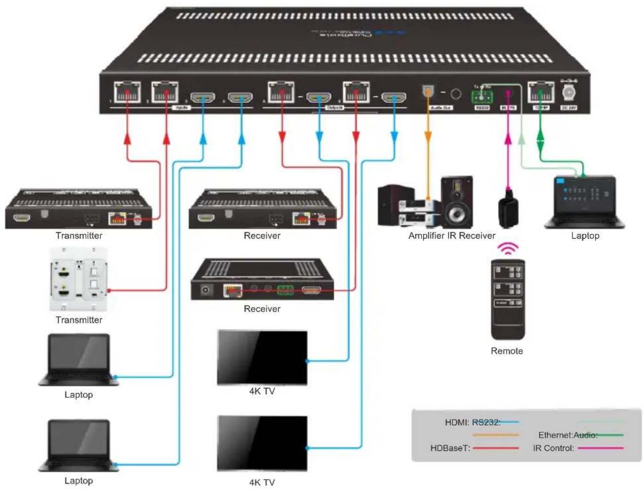
flowchart
graph TD
    A["Server"] -->|Data Bus| B["Transmitter"]
    A -->|Data Bus| C["Receiver"]
    A -->|Data Bus| D["Amplifier IR Receiver"]
    A -->|Data Bus| E["Laptop"]
    A -->|Data Bus| F["Laptop"]
    A -->|Data Bus| G["4K TV"]
    A -->|Data Bus| H["4K TV"]
    A -->|Data Bus| I["Remote"]
    style A fill:#f9f,stroke:#333
    style B fill:#ccf,stroke:#333
    style C fill:#ccf,stroke:#333
    style D fill:#cfc,stroke:#333
    style E fill:#fcc,stroke:#333
    style F fill:#fcc,stroke:#333
    style G fill:#cff,stroke:#333
    style H fill:#ffc,stroke:#333
    style I fill:#ffc,stroke:#333
    style_J["4K TV"] --> K["Transmitter"]
    J --> L["Laptop"]
    J --> M["Receiver"]
    J --> N["Laptop"]
    J --> O["Receiver"]
    J --> P["Amplifier IR Receiver"]
    J --> Q["Laptop"]
    J --> R["Remote"]
    style A fill:#ccc,stroke:#333
    style B fill:#ccc,stroke:#333
    style C fill:#ccc,stroke:#333
    style D fill:#ccc,stroke:#333
    style E fill:#ccc,stroke:#333
    style F fill:#ccc,stroke:#333
    style G fill:#ccc,stroke:#333
    style H fill:#ccc,stroke:#333
    style I fill:#ccc,stroke:#333
    style J fill:#ccc,stroke:#333
    style K fill:#ccc,stroke:#333
    style L fill:#ccc,stroke:#333
    style M fill:#ccc,stroke:#333
    style N fill:#ccc,stroke:#333
    style O fill:#ccc,stroke:#333
    style P fill:#ccc,stroke:#333
    style Q fill:#ccc,stroke:#333
    style R fill:#ccc,stroke:#333
5. Button Control
5.1 Manual Switching
When the switcher is in manual switching mode, the Auto button LED goes out. Please follow the below steps to switch input source to output channel.
1) Press Select button at Out A block to select input source for HDBaseT + HDMI output A, and the corresponding source LED turns green.
2) Press Select button at Out B block to select input source for HDBaseT + HDMI output B, and the corresponding source LED turns green.
5.2 Auto Switching
Press and hold Select button at least 3 seconds at Out A block to enable auto switching mode for output A, and then the Auto LED will turn green.
Press and hold Select button at least 3 seconds at Out B block to enable auto switching mode for output B, and then the Auto LED will turn green.
When in auto switching mode, the switcher will switch according to the following rules:
- The switcher will switch to the first available active input starting at input 1 to 4.
- New input: The switcher will automatically select the new input once detecting a new input.
- Reboot: If power is restored to the switcher, it will automatically reconnect the input before powered off.
- Source removed: When an active source is removed, the switcher will switch to the first available active input starting at HDMI input 1.
- Detection method: TMDS or 5V (The default is 5V and it can be selected by RS232 commands).
- The current input source can be switched by Select button on front panel, IR remote and RS232 commands, and the switcher doesn't exit the auto switching mode.
Note: In auto switching mode, press and hold the Select button at least 3 seconds to enable manual switching mode, but the input source will not be switched.
6. IR Remote Control
Connect IR receiver to the IR EYE port, the switcher can be controlled by the following IR remote.
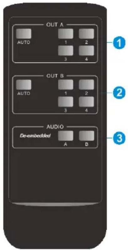
text_image
OUT A AUTO 1 2 3 4 OUT B AUTO 1 2 3 4 AUDIO De-embedded A B① 1-4: Press 1-4 button to select corresponding input source for output A.
AUTO: Press the button to enable auto switching mode for output A.
② 1-4: Press 1-4 button to select corresponding input source for output B.
AUTO: Press the button to enable auto switching mode for output B.
③ De-embedded: Press A or B button to select output A or output B de-embedded audio source for SPDIF + Stereo audio output.
7. GUI Control
The matrix can be controlled via TCP/IP. The default IP settings are:
IP Address: 192.168.0.178
Subnet Mask: 255.255.255.0
Gateway: 192.168.0.1
Type 192.168.0.178 in the internet browser, it will enter the below log-in webpage:
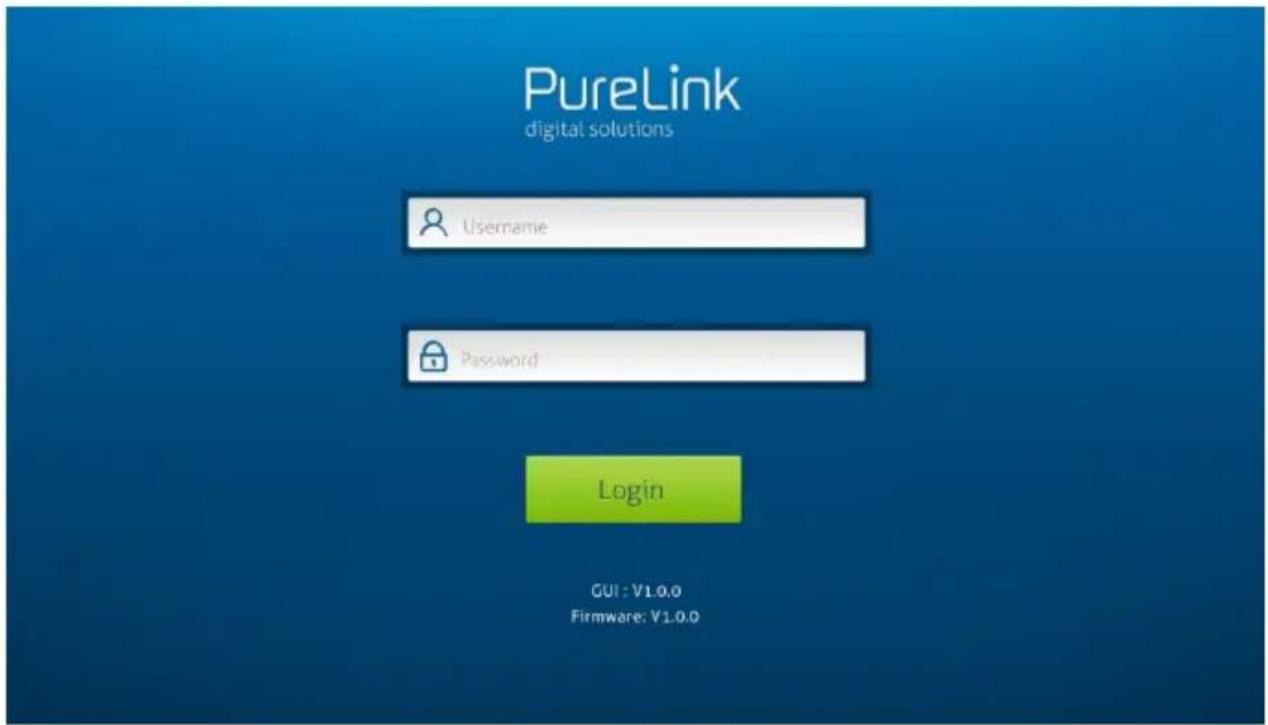
text_image
PureLink digital solutions Username Password Login GUI : V1.0.0 Firmware: V1.0.0There are three selectable usernames:
| Username | Password | Access Tab |
| admin | admin | All tabs |
| user1 | user1 | Video, Audio and Configuration tabs |
| user2 | user2 | Video tab. |
The username and password can be changed via Security tab.
Here we login as "admin" as an example to introduce each GUI tab.
7.1 Video Tab
text_image
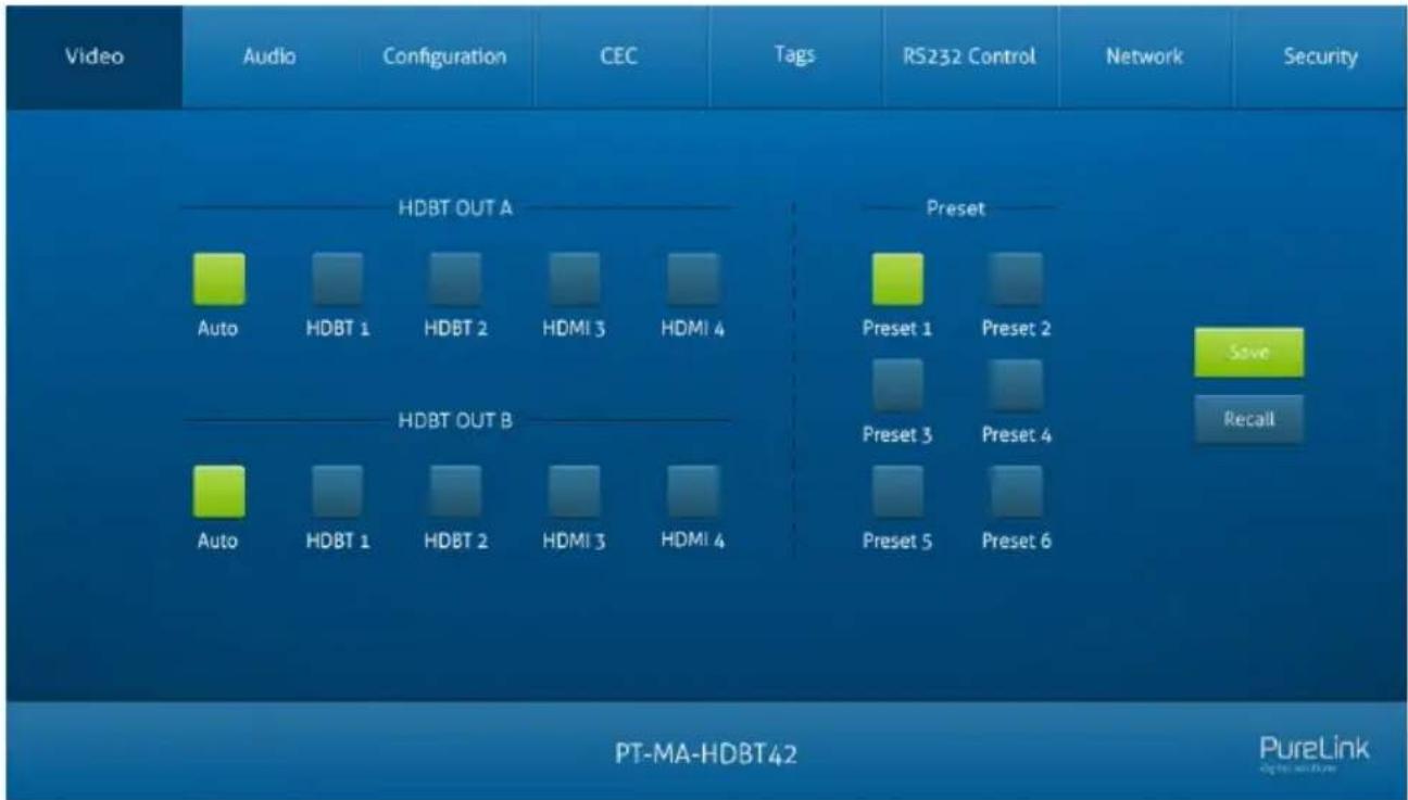
Video Audio Configuration CEC Tags RS232 Control Network Security HDBT OUT A Auto HDBT 1 HDBT 2 HDMI 3 HDMI 4 HDBT OUT B Auto HDBT 1 HDBT 2 HDMI 3 HDMI 4 Preset Preset 1 Preset 2 Preset 3 Preset 4 Preset 5 Preset 6 Save Recall PT-MA-HDBT42 PureLink- HDBT OUT A: Select input source 1\~4 for output A. Click Auto to enable auto switching mode for output A.
- HDBT OUT B: Select input source 1\~4 for output B. Click Auto to enable auto switching mode for output B.
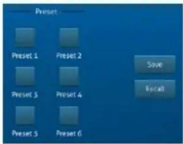
Use the 6 numbered buttons under preset area to save and load layout presets.
- To save a given layout, first click one of the numbered buttons, then click the Save button.
- To load a previously saved layout, first click one of the numbered buttons, then click the Recall button.
text_image
Preset Preset 1 Preset 2 Preset 3 Preset 4 Preset 5 Preset 6 Save Recall7.2 Audio Tab

text_image
Video Audio Configuration CEC Tags RS232 Control Network Security HDBT OUT A De-embedded HDBT OUT B De-embedded PT-MA-HDBT42 PureLink- Select HDBT OUT A de-embedded audio, HDBT OUT B de-embedded audio for SPDIF + Stereo audio outputs.
7.3 Configuration Tab
7.3.1 PoC Setting

text_image
Video Audio Configuration CEC Tags RS232 Control Network Security PoC EDID On Off HDBT IN 1 HDBT IN 2 HDBT OUT A HDBT OUT B Confirm PT-MA-HDBT42 PureLink digital resources- Turn on/off PoC for HDBT input 1\~2 and HDBT output A\~B.
7.3.2 EDID Setting
text_image
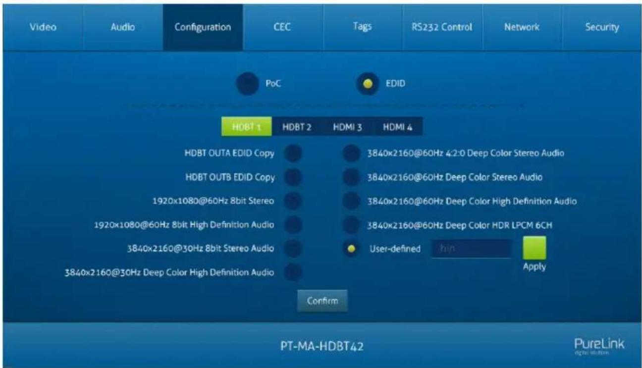
Video Audio Configuration CEC Tags RS232 Control Network Security PoC EDID HDBT 1 HDBT 2 HDMI 3 HDMI 4 HDBT OUTA EDID Copy 3840x2160@60Hz 4:2:0 Deep Color Stereo Audio HDBT OUTB EDID Copy 3840x2160@60Hz Deep Color Stereo Audio 1920x1080@60Hz 8bit Stereo 3840x2160@60Hz Deep Color High Definition Audio 1920x1080@60Hz 8bit High Definition Audio 3840x2160@60Hz Deep Color HDR LPCM 6CH 3840x2160@30Hz 8bit Stereo Audio User-defined Apply 3840x2160@30Hz Deep Color High Definition Audio Confirm PT-MA-HDBT42 PureLink dark.shin.com- Select a compatible built-in EDID for the selected input source, and then click Confirm to save setting.
- Upload user-defined EDID by the below steps:
1) Prepare the EDID file (.bin) on the control PC.
2) Select the User-defined.
3) Click the box, and then select the EDID file (.bin) according to the tooltip.
4) Click Apply to upload the user-defined EDID.
5) If invoke the user-defined EDID, select it and then click Confirm.
7.4 CEC Tab
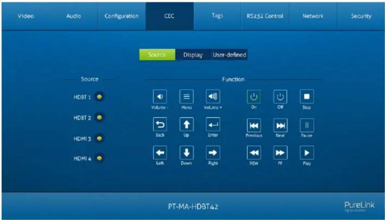
If the input source devices, output devices support CEC, they can be controlled via the following CEC interface.
1) Source Device Control
text_image
Video Audio Configuration CEC Tags RS232 Control Network Security Source Display User-defined Source HDBT 1 HDBT 2 HDMI 3 HDMI 4 Function Volume - Menu Volume On Off Stop Back Up Enter Previous Next Pause Left Down Right REW FF Play PT-MA-HDBT42 PureLink- Select one or several input source devices to be controlled, and then press function buttons.
2) Display Device Control
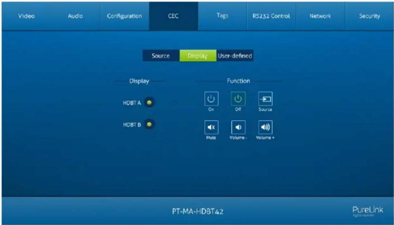
text_image
Video Audio Configuration CEC Tags RS232 Control Network Security Source Display User-defined Display Function HDBT A On Off Source HDBT B Mute Volume - Volume * PT-MA-HDBT42 PureLink digital-inners- Select one or several output devices to be controlled, and then press function buttons.
Note: The CEC standard is mainly formulated by TV manufacturers, and is mainly compatible with its TVs and Blu-ray Players, and may not be compatible with the source devices of other manufacturers, such as various set top boxes, Apple TV, etc.
3) User-defined Control
The switcher also provides user-defined CEC functions, the CEC command can be edited and saved in the Trigger box.
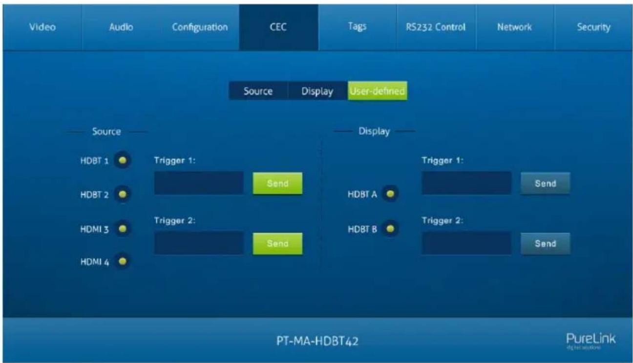
flowchart
graph TD
    A["Video"] --> B["Audio"]
    B --> C["Configuration"]
    C --> D["CEC"]
    D --> E["Tags"]
    E --> F["RS232 Control"]
    F --> G["Network"]
    G --> H["Security"]

    I["Source"] --> J["HDBT 1"]
    I --> K["HDBT 2"]
    I --> L["HDMI 3"]
    I --> M["HDMI 4"]

    N["Display"] --> O["Trigger 1:"]
    N --> P["Trigger 2:"]
    N --> Q["Send"]

    R["User-defined"] --> S["User-defined"]

    T["PT-MA-HDBT42"] --> U["PureLink"]
- Select the input source, and then type CEC command in the Trigger 1 or Trigger 2 box to control the selected source.
- Select the output display, and then type CEC command in the Trigger 1 or Trigger 2 box to control the selected display.
7.5 Tag Tab
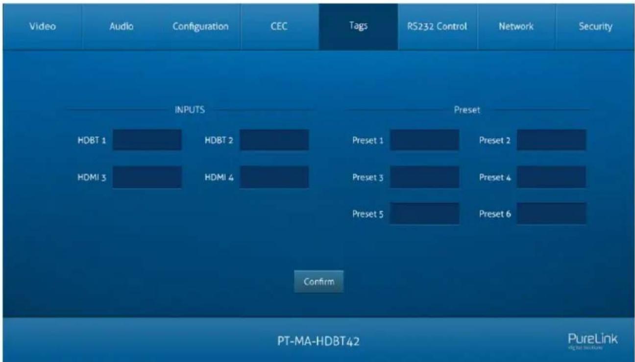
text_image
Video Audio Configuration CEC Tags RS232 Control Network Security INPUTS HDBT 1 HDBT 2 HDMI 3 HDMI 4 Preset Preset 1 Preset 2 Preset 3 Preset 4 Preset 5 Preset 6 Confirm PT-MA-HDBT42 PureLink digital security• INPUTS: Modify the label of input sources.
- Preset: Modify the label of presets.
7.6 RS232 Tab
1) RS232 Mode
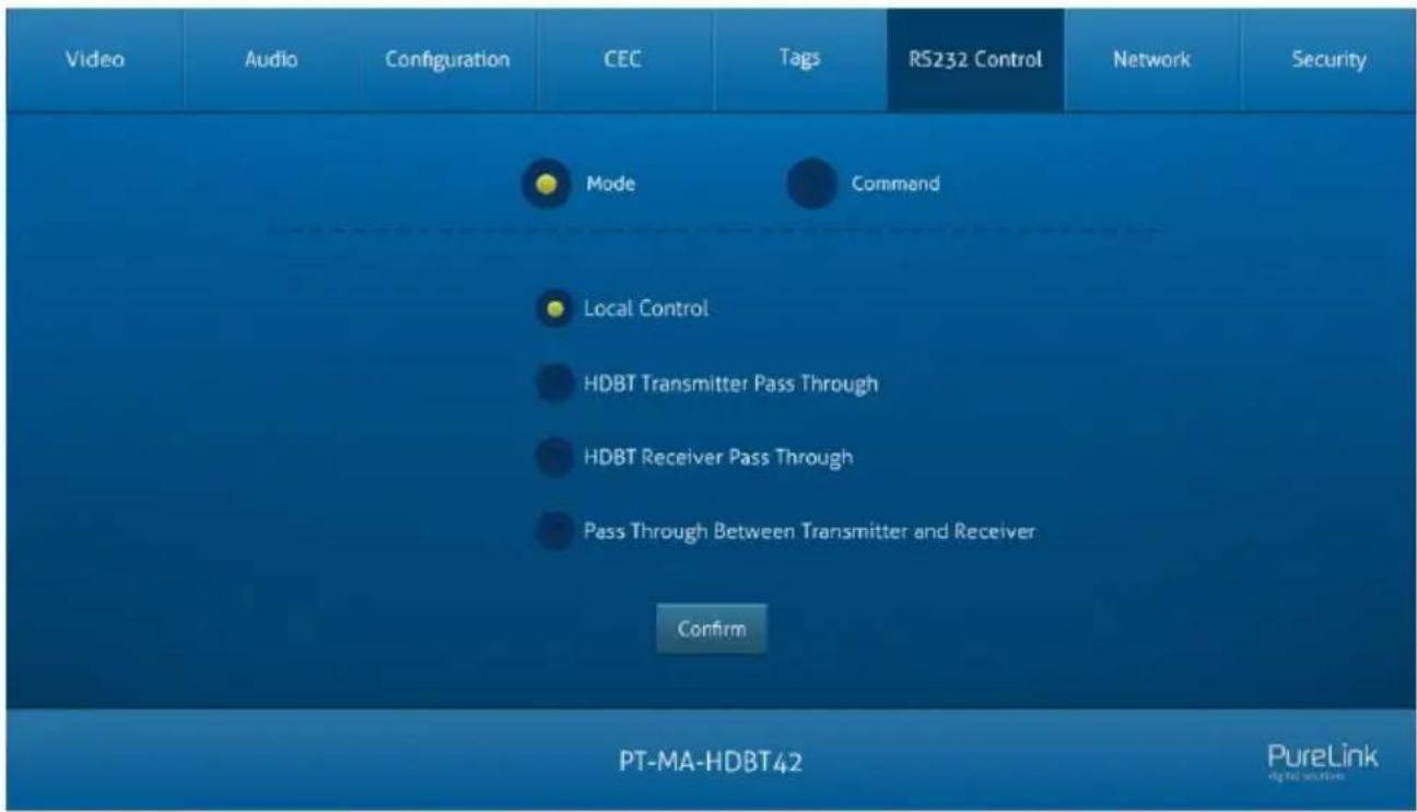
text_image
Video Audio Configuration CEC Tags RS232 Control Network Security Mode Command Local Control HDBT Transmitter Pass Through HDBT Receiver Pass Through Pass Through Between Transmitter and Receiver Confirm PT-MA-HDBT42 PureLink digital solutionSelect the RS232 mode in this tab.
- Local Control: The RS232 port of the switcher is used to connect control device (e.g. PC) to control the switcher.
- HDBT Transmitter Pass Through: Establish RS232 pass-through communication between the switcher and the HDBaseT transmitter.
- HDBT Receiver Pass Through: Establish RS232 pass-through communication between the switcher and the HDBaseT receiver.
- Pass Through Between Transmitter and Receiver: Establish RS232 pass-through communication between the HDBaseT transmitter and HDBaseT receiver.
2) RS232 Mode
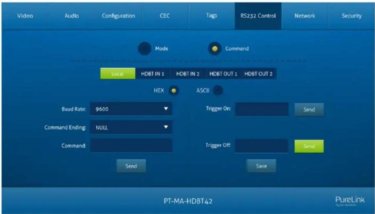
text_image
Video Audio Configuration CEC Tags RS232 Control Network Security Mode Command Local HDBT IN 1 HDBT IN 2 HDBT OUT 1 HDBT OUT 2 HEX ASCII Baud Rate: 9600 Trigger On: Send Command Ending: NULL Command: Trigger Off: Send Send Send Send PT-MA-HDBT42 PureLink digital solutions- Select command sending port.
√ Local: Send RS232 commands to control the local third-party which is connected to the RS232 port of the switcher.
√ HDBT In 1: Send RS232 commands to control the far-end third-party which is connected to the RS232 port of HDBaseT transmitter. The transmitter is connected to the HDBT input 1 port.
√ HDBT In 2: Send RS232 commands to control the far-end third-party which is connected to the RS232 port of HDBaseT transmitter. The transmitter is connected to the HDBT input 2 port.
√ HDBT Out 1: Send RS232 commands to control the far-end third-party (e.g. projector) which is connected to the RS232 port of HDBaseT receiver. The receiver is connected to the HDBT output 1 port.
√ HDBT Out 2: Send RS232 commands to control the far-end third-party (e.g. projector) which is connected to the RS232 port of HDBaseT receiver. The receiver is connected to the HDBT output 2 port.
- Set command format to HEX or ASCII.
• Baud Rate: Supports 2400, 4800, 9600, 19200, 38400, 57600 or 115200.
- Command Ending: NULL, CR, LF or CR+LF can be chosen.
- Command: Type command in this textbox, and then click Send to control the third-party device.
- Trigger On: Type Power On command in this box to turn on the third-party device.
- Trigger Off: Type Power Off command in this box to turn off the third-party device.
7.7 Network Tab
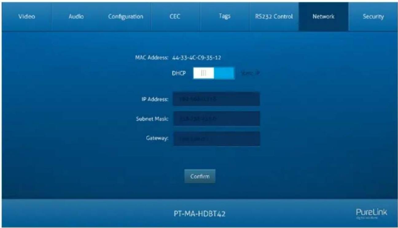
text_image
Video Audio Configuration CEC Tags RS232 Control Network Security MAC Address: 44-33-4C-C9-35-12 DHCP State IP IP Address: 102-108-1175 Subnet Mask: 128-132-139.0 Gateway: 1=1=0.07 Confirm PT-MA-HDBT42 PureLink digital security- Static IP or Dynamic Host Configuration Protocol (DHCP).
- Modify the static IP Address, Subnet Mask, and Gateway.
7.8 Security Tab
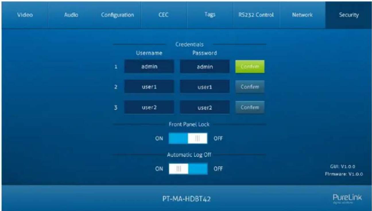
text_image
Video Audio Configuration CEC Tags RS232 Control Network Security Credentials Username Password 1 admin admin Confirm 2 user1 user1 Confirm 3 user2 user2 Confirm Front Panel Lock ON OFF Automatic Log Off ON OFF GUI: V1.0.0 Firmware: V1.0.0 PT-MA-HDBT42 PureLink- Modify username and password.
- Lock or unlock the front panel buttons.
- Enable or disable automatic log-off mode.
7.9 GUI Upgrade
Please visit at http://192.168.0.178:100 for GUI online upgrade.
Type the username and password (the same as the GUI log-in setting, modified password will be available only after rebooting) to login the configuration interface. After that, click Administration in the source menu to get to Upload Firmware as shown below:
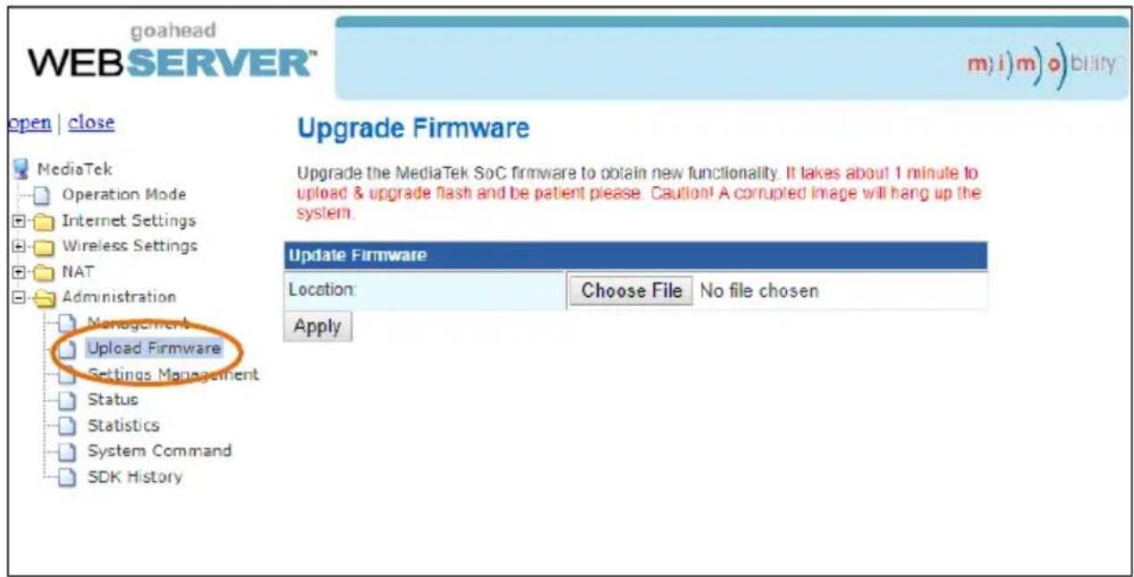
text_image
goahead WEBSERVER™ m) i) m) o) bility open | close Upgrade Firmware Upgrade the MediaTek SoC firmware to obtain new functionality. It takes about 1 minute to upload & upgrade flash and be patient please. Caution! A corrupted image will hang up the system. Update Firmware Location: Choose File No file chosen Apply MediaTek Operation Mode Internet Settings Wireless Settings NAT Administration Management Upload Firmware Settings Management Status Statistics System Command SDK HistorySelect the desired update file and press Apply, it will start upgrading then.
8. RS232 Control
8.1 RS232 Control Connection
8.1.1 Control the Matrix Switcher
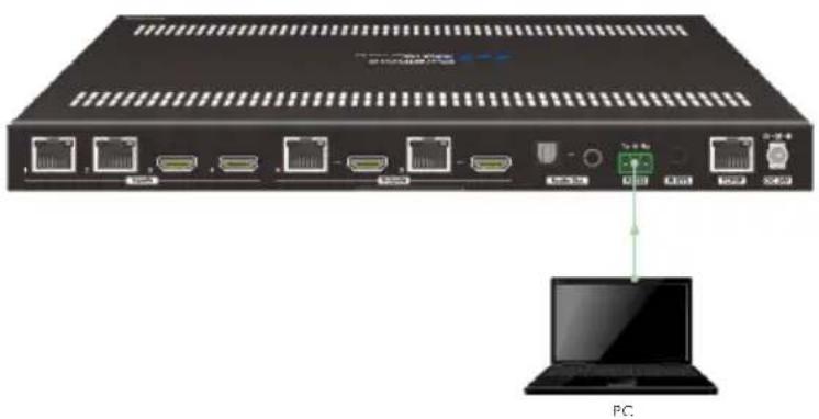
1) To control the matrix switcher from a local PC, the 3-pin to DB9 RS232 cable is used to connect between the matrix and PC. The connection diagram is shown as below:
natural_image
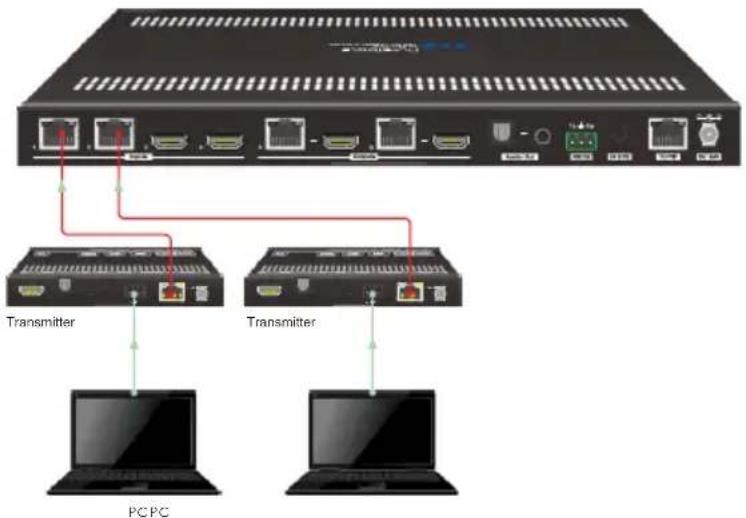
Front view of a network switch device with ports and an external laptop (no visible text or symbols)2) To control the matrix switcher from remote transmitter location, please connect one or two PCs to the RS232 ports of HDBaseT transmitters with the 3-pin to DB9 RS232 cables. The matrix switcher can be controlled by any one of PCs, the connection diagram is shown as below:
text_image
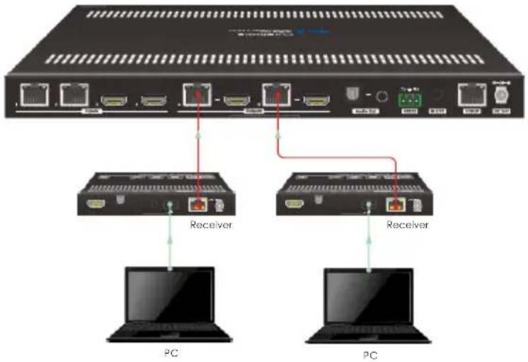
Transmitter Transmitter PCPC3) To control the matrix switcher from remote receiver location, please connect one or two PCs to the RS232 ports of HDBaseT receivers with the 3-pin to DB9 RS232 cables. The matrix switcher can be controlled by any one of PCs, the connection diagram is shown as below:
text_image
Receiver Receiver PC PC8.1.2 RS232 Pass-through Between Matrix Switcher and Transmitter
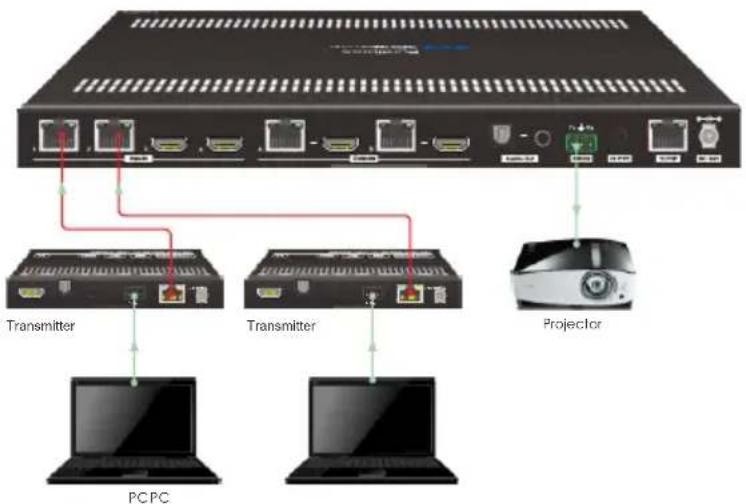
1) To control local third-party device from transmitter location, first determine which HDBaseT transmitter is connected to. Next, connect a PC to the RS232 port of HDBaseT transmitter, then connect a third-party device (e.g. projector) to the RS232 port of matrix switcher, the connection diagram is shown as below:
text_image
Transmitter Transmitter Projector PCPC2) To control remote third-party device from matrix switcher location, first determine which HDBaseT transmitter is connected to. Next, connect a third-party device (e.g. projector) to the RS232 port of HDBaseT transmitter, then connect a PC to the RS232 port of matrix switcher, the connection diagram is shown as below:
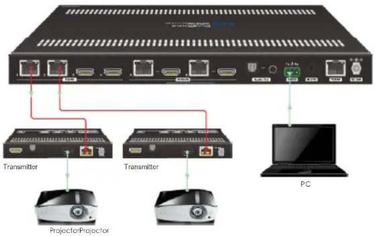
text_image
Transmitter Transmitter ProjectorProjector PC8.1.3 RS232 Pass-through Between Matrix Switcher and Receiver
1) To control local third-party device from remote receiver location, first determine which HDBaseT receiver is connected to. Next, connect a PC to the RS232 port of HDBaseT receiver, then connect a third-party device (e.g. projector) to the RS232 port of matrix switcher, the connection diagram is shown as below:
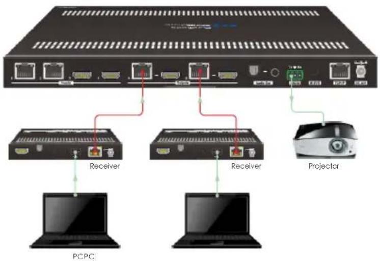
text_image
Receiver Receiver Projector PCPC2) To control remote third-party device from local matrix switcher location, first determine which HDBaseT receiver is connected to. Next, connect a PC to the RS232 port of matrix switcher, then connect a third-party device (e.g. projector) to the RS232 port of HDBaseT receiver, the connection diagram is shown as below:
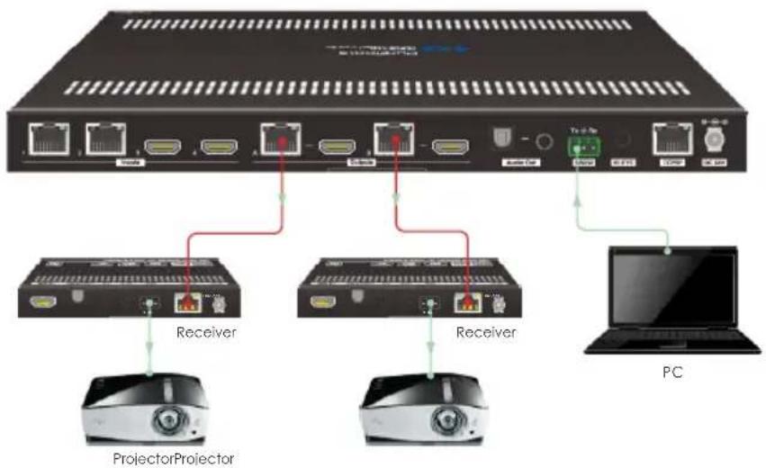
text_image
PC Receiver Receiver ProjectorProjector8.1.4 RS232 Pass-through Between Transmitter and Receiver
1) To control third-party device from transmitter location, first determine which HDBaseT receiver is connected to. Next, connect a third-party device (e.g. projector) to the RS232 port of HDBaseT receiver, then connect a PC to the RS232 port of HDBaseT transmitter, the connection diagram is shown as below:
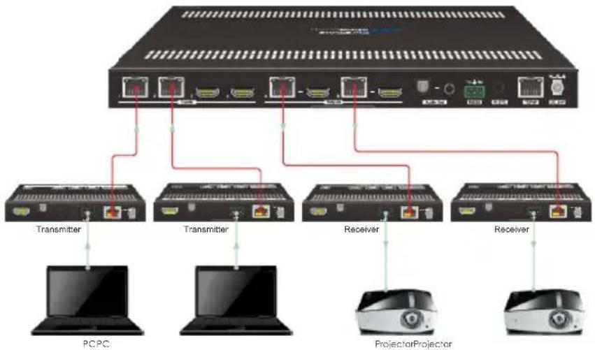
flowchart
graph TD
    A["Switch"] --> B["Transmitter"]
    A --> C["Transmitter"]
    A --> D["Receiver"]
    A --> E["Receiver"]
    B --> F["PCPC"]
    C --> G["ProjectorProjector"]
    D --> H["ProjectorProjector"]
    E --> I["ProjectorProjector"]
2) To control third-party device from receiver location, first determine which HDBaseT transmitter is connected to. Next, connect a third-party device (e.g. projector) to the RS232 port of HDBaseT transmitter, then connect a PC to the RS232 port of HDBaseT receiver, the connection diagram is shown as below:
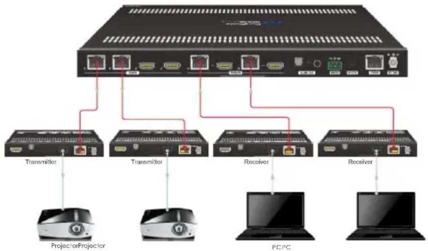
flowchart
graph TD
    A["Server"] --> B["Transmitter"]
    A --> C["Transmitter"]
    A --> D["Receiver"]
    A --> E["Receiver"]
    B --> F["Projector/Projector"]
    C --> G["Projector/Projector"]
    D --> H["PCPC"]
    E --> I["PCPC"]
8.2 RS232 Control Software
Connect the RS232 port to control device (e.g. PC) with RS232 cable. The switcher can be controlled by sending RS232 commands.
Here take the software docklight as an example.
- Installation
Please download the latest Software Version from the link below:
https://docklight.de/download/Docklight.zip
Then follow the installation wizard for installation on Windows 7 and 10.
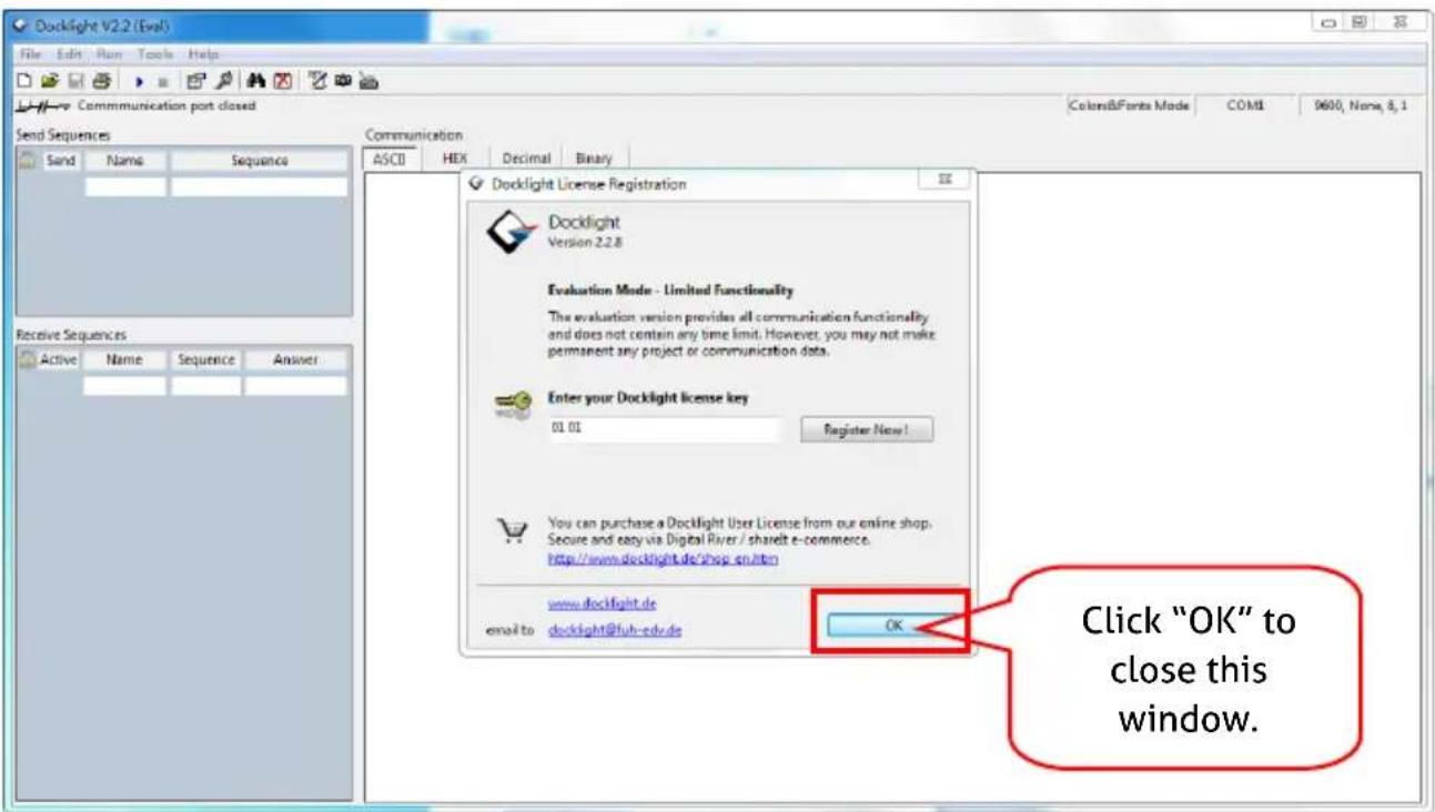
After the installation, Docklight can be run for the first time and should look like the below screen shot:
Registration is not necessary unless you wish to save settings on exit, so unless you wish to register click on "OK" to close the window.
text_image
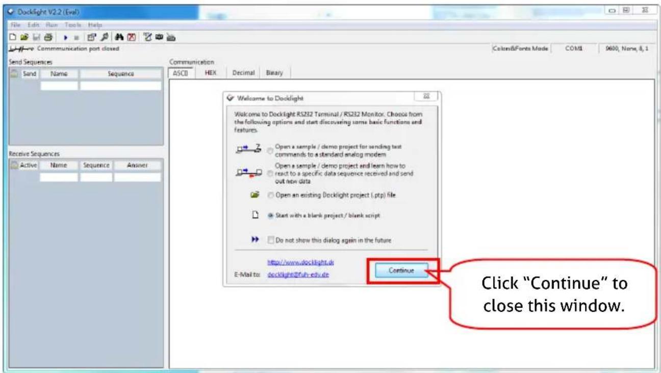
Docklight V2.2 (Eval) File Edit Run Tools Help Communication port closed Send Sequences Send Name Sequences Receive Sequences Active Name Sequence Answer Docklight License Registration Docklight Version 2.2.8 Evaluation Mode - Limited Functionality The evaluation version provides all communication functionality and does not contain any time limit. However, you may not make permanent any project or communication data. Enter your Docklight license key 01.01 Register Now! You can purchase a Docklight User License from our online shop. Secure and easy via Digital River / shareIt e-commerce. http://www.docklight.de/shop_en.html www.docklight.de email to docklight@fuh-edv.de OK Click "OK" to close this window.The next pop-up window can also be closed with "Continue". An empty project is enough to send and receive commands easily (The default setting is always "Start with a blank project / blank script")
text_image
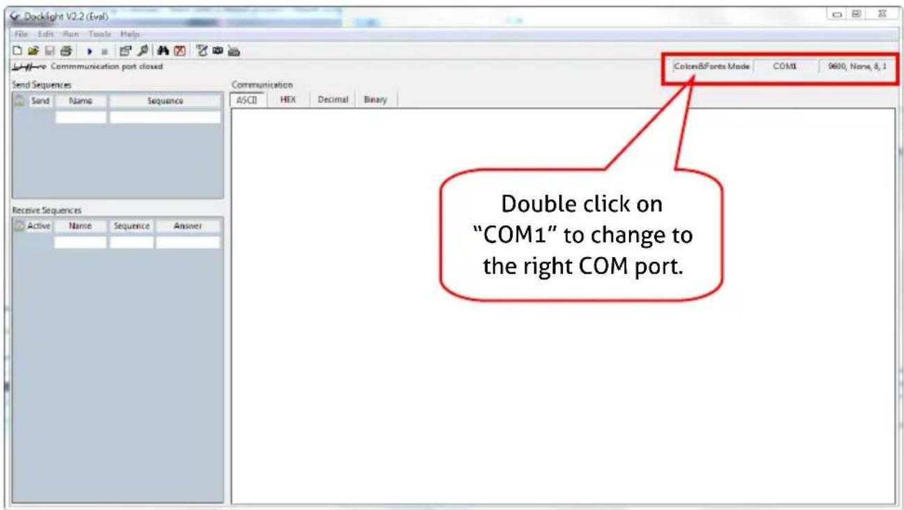
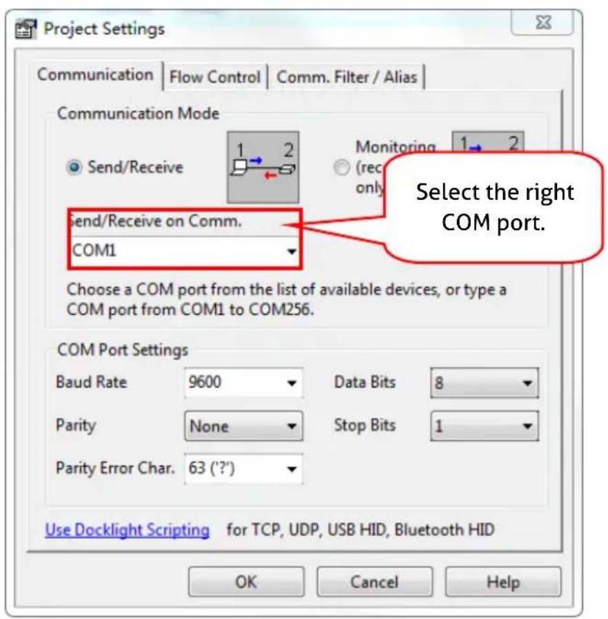
Docklight V2.2 (Eval) File Edit Run Tools Help Communication port closed Send Sequences Send Name Sequence Exchange Sequences Active Name Sequence Answer Welcome to Docklight Welcome to Docklight RS232 Terminal / RS232 Monitor. Choose from the following options and start discovering some basic functions and features. Open a sample / demo project for sending test commands to a standard analog modem Open a sample / demo project and learn how to react to a specific data sequence received and send out new data Open an existing Docklight project (.ptp) file Start with a blank project / blank script Do not show this dialog again in the future http://www.docklight.dk E-Mail to: docklight@2fuh.edu.de Continue Click "Continue" to close this window.Now you are in the main view, where commands are sent and feedback is received. The next step is to select the correct COM port of the PC. To do this, double-click on "COM1" in the corresponding setup window.
text_image
Docklight V2.2 (Eval) File Edit Run Tools Help Communication port closed Send Sequences Sand Name Sequence Communication ASCII HEX Decimal Binary Double click on "COM1" to change to the right COM port. Send Sequences Active Name Sequence AnswerIn the following window, select the drop-down menu labeled "Send / Receive on Comm Channel", select the appropriate COM port and then click on "OK" at the bottom right corner.
All other settings can be left at default for most applications, but refer to device RS232 settings to be sure.
text_image
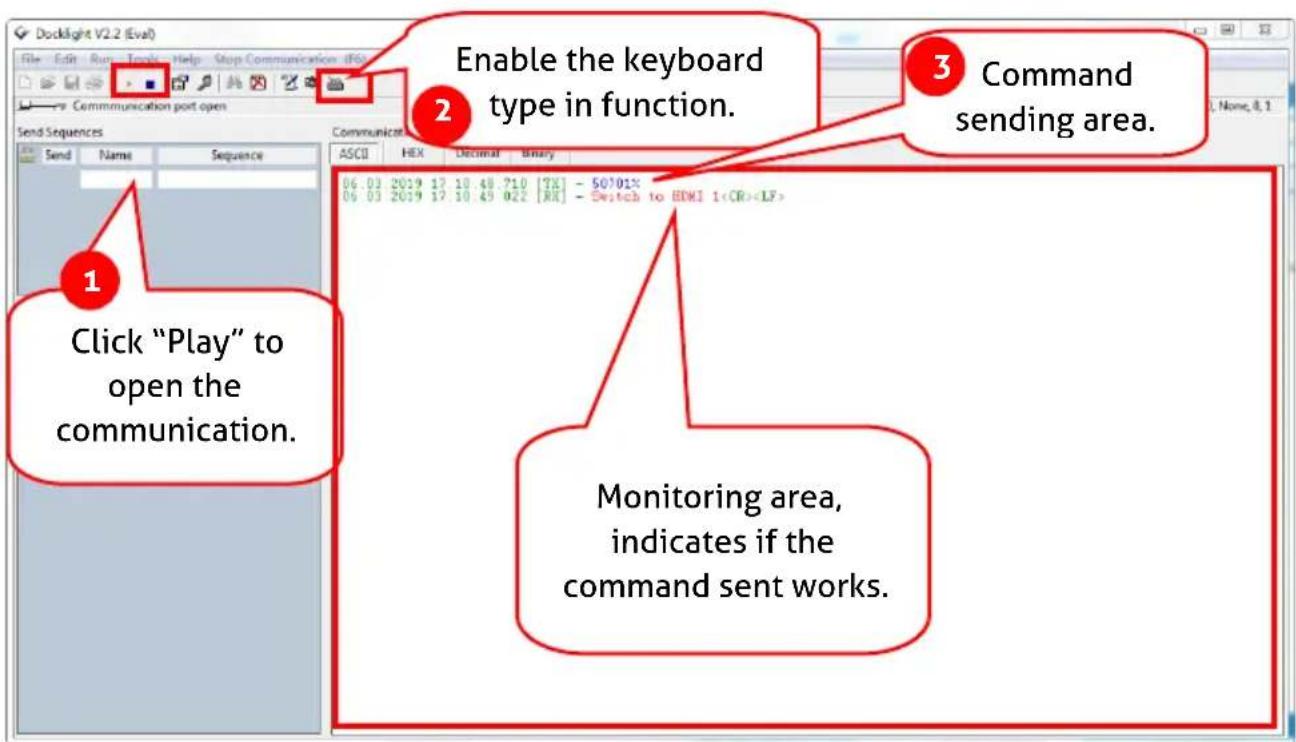
Project Settings Communication | Flow Control | Comm. Filter / Alias | Communication Mode Send/Receive 1 2 Monitoring 1 2 Rec only Send/Receive on Comm. COM1 Choose a COM port from the list of available devices, or type a COM port from COM1 to COM256. COM Port Settings Baud Rate 9600 Data Bits 8 Parity None Stop Bits 1 Parity Error Char. 63 (?') Use Docklight Scripting for TCP, UDP, USB HID, Bluetooth HID OK Cancel HelpIn order to be able to send commands, open communication with the device by clicking on "Play". (1)
Then the keyboard function must be activated, so that commands can be written in the "communication window". (2)
Finally enter the command, for example "50701%". This is then confirmed by pressing "Enter" to send. Any response from the connected device will appear in red. (3)
text_image
Enable the keyboard type in function. Command sending area. Click "Play" to open the communication. Monitoring area, indicates if the command sent works.8.3 RS232 Communication Commands
Communication protocol: RS232 Communication Protocol
Baud rate: 9600
Data bit: 8
Stop bit: 1
Parity bit: none
Note:
- In the commands, "[and "] are symbols for easy reading and do not need to be typed in actual operation.
- Please remember to end the commands with the ending symbols "." or ";";
- Type the command carefully, it is case-sensitive.
- The command ending is "
"
8.3.1 System Setting
| Command | Description | Command Example and Feedback |
| >SetPowerOn [param1] | Enter/ exit standby mode. [param1] = En, DisEn - Power on.Dis - Standy mode. | >SetPowerOn En>SetPowerOn Dis |
| >GetFirmwareVersion | Get the firmware version. | |
| >SetFactoryReset | Reset to factory default. | |
| >SetReboot | Device reboot. | |
| >GetStatus | Get system working status. | ... |
| >SetRS232Baudrate [param1] | Set the serial baud rate of matrix switcher to [param1]. [param1] = 1~71- 115200 2 - 57600 3 - 384004 - 19200 5 - 9600 6 - 48007 - 2400 | >SetRS232Baudrate 3 |
| >GetRS232Baudrate | Get the baud rate of switcher. | |
| >SetKeyboardLock [param1] | Lock/unlock front panel buttons. [param1] = En, DisEn - LockDis - Unlock | >SetKeyboardLock En>SetKeyboardLock Dis |
| >GetKeyboardLock | Get the front panel locking status. | |
| >SetSignalDet [param1] | Set the input signal detection method.[param1] = 5V, TMDS. | >SetSignalDet TMDS>SetSignalDet 5V |
| >GetSignalDet | Get the input signal detection method. | |
| >Set5VSource [param1] | In auto switching mode, set the detection method of HDBT inputs to detect the signal of transmitter to ensure different transmitters can be used.[param1] = HW, FW.HW - Hardware detection.FW - Firmware detection. | >Set5VSource HW>Set5VSource FW |
| >Get5VSource | Get the detection method of HDBT inputs to detect the signal of transmitter to ensure different transmitters can be used. | |
| >UpDownScaler [param1] [param2] | Set the down-scaling function of output [param1].[param1] = OutA, OutB.[param1] = Null, all outputs.[param2] = En, Dis.En - Enable down-scaling function.Dis - Disable down-scaling function. | >UpDownScaler En>UpDownScaler Dis |
| >GetDownScaler [param1] | Get the down-scaling function setting status of output [param1].[param1] = OutA, OutB.[param1] = Null, all outputs. | >GetDownScaler |
| >SetDhcp [param1] | Enable/disable DHCP (Dynamic Host Configuration Protocol).[param1] = En, Dis.En - Enable DHCP.Dis - Disable DHCP. | >SetDhcp En>SetDhcp Dis |
| >GetDhcp | Get DHCP status. | |
| >SetIpAddr [param1].[param2].[param3].[param4] | Set GUI IP.[param1] = 0 ~ 255.[param2] = 0 ~ 255.[param3] = 0 ~ 255.[param4] = 0 ~ 255. | >SetIpAddr 192.168.0.178 |
| >GetIpAddr | Get GUI IP. | |
| >SetSubnetMask [param1].[param2].[param3].[param4] | Set the subnet mask address of the GUI.[param1] = 0 ~ 255.[param2] = 0 ~ 255.[param3] = 0 ~ 255.[param4] = 0 ~ 255. | >SetSubnetMask 255.255.255.0 |
| >GetSubnetMask | Get the subnet mask address of the GUI. | |
| >SetGateWay [param1].[param2].[param3].[param4] | Set the gateway address of the GUI.[param1] = 0 ~ 255.[param2] = 0 ~ 255.[param3] = 0 ~ 255.[param4] = 0 ~ 255. | >SetGateWay 192.168.0.1 |
| >GetGateWay | Get the gateway address of the GUI. | |
| >SetPoCOut [param1][param2] | Turn on/off PoC.[param1] = IN1, IN2, OutA, OutB, Null.IN1 - HDBT input 1.IN2 - HDBT input 2.OutA - HDBT output A.OutB - HDBT output B.Null - all HDBT inputs and outputs.[param2] = En, DisEn - Turn on PoC.Dis - Turn off PoC. | >SetPoCOut Dis>SetPoCOut En>SetPoCOut IN1 Dis>SetPoCOut IN1 En>SetPoCOut IN2 Dis>SetPoCOut IN2 En>SetPoCOut OutA Dis>SetPoCOut OutA En>SetPoCOut OutB Dis>SetPoCOut OutB En |
| >GetPoCOut [param1] | Get PoC setting status.[param1] = IN1, IN2, OutA, OutB, Null.IN1 - HDBT input 1.IN2 - HDBT input 2.OutA - HDBT output A.OutB - HDBT output B.Null - all HDBT inputs and outputs. | >GetPoCOut>GetPoCOut IN1>GetPoCOut IN2>GetPoCOut OutA>GetPoCOut OutB |
8.3.2 Signal Switching
| Command | Description | Command Example and Response |
| >SetAV [param1][param2] | Switch video input [param2] to video output [param1].[param1] = OutA, OutB.[param1] = Null, all outputs.[param2] = H1, H2, H3, H4H1 - HDBT input 1.H2 - HDBT input 2.H3 - HDMI input 3.H4 - HDMI input 4. | >SetAV H1>SetAV OutA H1>SetAV OutB H1 |
| >GetAV [param1] | Get input source for output [param1].[param1] = OutA, OutB.[param1] = Null, all outputs. | >GetAV>GetAV OutA>GetAV OutB |
| >SetAutoSwitch [param1] [param2] | Enable/disable auto switching mode for output[param1].[param1] = OutA, OutB.[param1] = Null, all outputs.[param2] = En, DisEn - EnableDis - Disable | >SetAutoSwitch En>SetAutoSwitch Dis>SetAutoSwitch OutA En>SetAutoSwitch OutA Dis>SetAutoSwitch OutB En>SetAutoSwitch OutB Dis |
| >GetAutoSwitch [param1] | Get the auto switching mode setting of output[param1].[param1] = OutA, OutB.[param1] = Null, all outputs. | >GetAutoSwitch>GetAutoSwitch OutA>GetAutoSwitch OutB |
| >SaveScreenMode [param1] | Store the current switching status to present [param1]. [param1] = 1~6. | >SaveScreenMode 1 |
| >RecallScreenMode [param1] | Recall present [param1]. [param1] = 1~6. | >RecallScreenMode 2 |
| >ClearScreenMode [param1] | Clear present [param1]. [param1] = 1~6. | >ClearScreenMode 2 |
8.3.3 Audio Setting
| Command | Description | Command Example and Response |
| >SetAudioSrc [param1] | Set the audio source of SPDIF + Stereo audio outputs. [param1] = OutA, OutB OutA - Audio de-embedding from output A. OutB - Audio de-embedding from output B. | >SetAudioSrc OutA >SetAudioSrc OutB |
| >SetSpdif [param1] | Mute/unmute the SPDIF audio output. [param1] = Mute, Unmute | >SetSpdif Mute >SetSpdif Unmute |
| >Setlis [param1] | Mute/unmute the Stereo (I2S) audio output. [param1] = Mute, Unmute | >Setlis Mute >Setlis Unmute |
| >GetAudioSta | Get audio output status. |
8.3.4 HDCP and EDID Setting
| Command | Description | Command Example and Response |
| >SetHdcpOutput [param1] [param2] | Set the HDCP mode of output. [param1] = OutA, OutB. [param1] = Null, all outputs. [param2] = Active, Passive, Off. • Active - HDCP 1.4 • Passive - Follows the HDCP of input signal, supports up to HDCP 2.2. • Off - No HDCP content. | >SetHdcpOutput Active >SetHdcpOutput Passive >SetHdcpOutput Off |
| >GetHdcpOutput | Get HDCP setting status of output. | |
| >SetUpdateEdid [param1] | Upload a user-defined EDID. The EDID can be saved for invoking at any time. When the command applied, system prompts to upload the EDID file (.bin). Operation will be cancelled in 10 seconds. [param1] = 1, 2. 1 - Upload user-defined EDID 1. 2 - Upload user-defined EDID 2. | >SetUpdateEdid 1 |
| >SetEdidMode [param1] [param2] | Set the EDID of input. [param1] = H1, H2, H3, H4, NullH1 - HDBT input 1.H2 - HDBT input 2.H3 - HDMI input 3.H4 - HDMI input 4.Null - All inputs. [param2] = 1~121 - HDBT OUTA EDID Copy2 - HDBT OUTB EDID Copy3 - 1920x1080@60Hz 8bit Stereo4 - 1920x1080 8bit High Definition Audio5 - 3840x2160@30Hz 8bit Stereo Audio6 - 3840x2160@30Hz Deep Color High Definition Audio7 - 3840x2160@60Hz 4:2:0 Deep Color Stereo Audio8 - 3840x2160@60Hz Deep Color Stereo Audio9 - 3840x2160@60Hz Deep Color High Definition Audio10 - 3840x2160@60Hz Deep Color HDR LPCM 6CH11 - user-defined EDID 112 - user-defined EDID 2 | >SetEdidMode 8>SetEdidMode H1 8>SetEdidMode H2 8>SetEdidMode H3 8>SetEdidMode H4 8 |
| >GetEdidMode [param1] | Get the EDID of input. [param1] = H1, H2, H3, H4, NullH1 - HDBT input 1.H2 - HDBT input 2.H3 - HDMI input 3.H4 - HDMI input 4.Null - All inputs. | >GetEdidMode>GetEdidMode H1>GetEdidMode H2>GetEdidMode H3>GetEdidMode H4 |
8.3.5 Third-party Device Control
| Command | Description | Command Example |
| >SetSrcCecControl [param1] [param2] | Send CEC command to control source device. [param1] = H1, H2, H3, H4, NullH1 - HDBT input 1.H2 - HDBT input 2.H3 - HDMI input 3.H4 - HDMI input 4.Null - All inputs. [param2] = 1~181 - Volume- 2 - Menu3 - Volume+ 4 - Back5 - Up 6 - Enter7 - Left 8 - Down9 - Right 10 - On11 - Off 12 - Stop13 - Previous 14 - Next15 - Pause 16 - REW17 - FF 18 - Play | >SetSrcCecControl H1 1>SetSrcCecControl H2 1>SetSrcCecControl H3 1>SetSrcCecControl H4 1 |
| >SetDisCecControl [param1] [param2] | Send CEC command to control display device. [param1] = OutA, OutB. [param1] = Null, all outputs. [param2] = 1~61 - On 2 - Off3 - Source 4 - Mute5 - Volume- 6 - Volume+ | >SetDisCecControl OutA 1>SetDisCecControl OutB 1 |
| >SetUserCecControl [param1] [param2] | Customize CEC command to control source or display device. [param1] = 1~61 - HDBT input 1.2 - HDBT input 2.3 - HDMI input 3.4 - HDMI input 4.5 - HDBT output A.6 - HDBT output B. [param2] = XX:XX......(HEX) | >SetUserCecControl 5 40:36 |
| >SetRS232Mode [param1] | Set the RS232 mode.[param1] = 1~41 - Local Control.2 - HDBT Transmitter Pass Through3 - HDBT Receiver Pass Through4 - Pass Through Between Transmitter and Receiver.Note:The RS232 mode can be set by GUI RS232 tab. | >SetRS232Mode 1>SetRS232Mode 2>SetRS232Mode 3>SetRS232Mode 4 |
| >GetRS232Mode | Get the RS232 control mode. | |
| >SetOn_[param1][param2]:[param3] | When the switcher is powered on, it automatically sends the saved RS232 command to control the far-end third-party devices.[param1] = A, H.A - ASCII command format.H - HEX command format.[param2] = 1~7 (Baud rate)1 - 115200 2 - 57600 3 - 384004 - 19200 5 - 9600 6 - 48007 - 2400[param3] = ASCII string or HEX string. (e.g. The string is used to turn on display device)Note:The command does not need command ending “”. | >SetOn_A_1:abc123 |
| >SetOff_[param1][param2]:[param4] | When the switcher is powered off, it automatically sends the saved RS232 command to control the far-end third-party devices.[param1] = A, H.A - ASCII command format.H - HEX command format.[param2] = 1~7 (Baud rate)1 - 115200 2 - 57600 3 - 384004 - 19200 5 - 9600 6 - 4 8007 - 2400 | >SetOff_A_1_2:abc123 |
| SetOff_Ascii (Baud)115200 (Repeat)2 abc123 | ||
| [param3] = 1, 21 - Send the RS232 string once.2 - Send the RS232 string two times.[param4] = ASCII string or HEX string. (e.g.The string is used to turn off display device)Note:The command does not need command ending “”. | ||
| >SetOffRptDly [param1] | When the above Off RS232 command is set to be repeated 2 times, the interval between the two commands can be set by this command. [param1] = 300-10000 (ms) | >SetOffRptDly 300 |
| >GetOffRptDly | Get the sending interval between two Off RS232 commands. | |
| >Send_A_[param1]_[param2]:[param3] | Send ASCII command to the desired RS232 port.[param1] = 1~51 - Local2 - HDBT input 13 - HDBT input 24 - HDBT output A.5 - HDBT output B.[param2] = 1~7 (Baud rate)1 - 115200 2 - 57600 3 - 384004 - 19200 5 - 9600 6 - 48007 - 2400[param3] = ASCII string.Note:The command does not need command ending “”. | >Send_A_1_1:abc123 |
| ... | ||
| >Send_H_[param1]_[param2]:[param3] | Send HEX command to the desired RS232 port.[param1] = 1~51 - Local2 - HDBT input 13 - HDBT input 24 - HDBT output A.5 - HDBT output B. | >Send_H_1_1:31 32 33 |
| ... | ||
| [param2] = 1-7 (Baud rate)1 - 115200 2 - 57600 3 - 384004 - 19200 5 - 9600 6 - 48007 - 2400[param3] = HEX stringNote:The command does not need command ending "". | ||
| >SetDisplayOn [param1] [param2] | Turn on/off the display devices by simultaneously sending CEC command and the saved RS232 command.[param1] = OutA, OutB.[param1] = Null, all outputs.[param2] = En, DisEn - Turn on display devices.Dis - Turn off display devices. | >SetDisplayOn En>SetDisplayOn Dis>SetDisplayOn OutA En>SetDisplayOn OutA Dis>SetDisplayOn OutB En>SetDisplayOn OutB Dis |
9. Firmware Upgrade
Please follow the steps below to upgrade the firmware by the FW port on the front panel:
1) Prepare the latest upgrade file (.bin) and rename it as "FW_MERG.bin".
2) Connect the switcher to the PC with USB to Micro USB cable, and then power on the switcher. The PC will automatically detect a U-disk named of "BOOTDISK".
3) Double-click the U-disk, a file named of "READY.TXT" would be shown.
4) Directly copy the latest upgrade file (.bin) to the "BOOTDISK" U-disk.
5) Reopen the U-disk to check the filename "READY.TXT" whether automatically becomes "SUCCESS.TXT", if yes, the firmware was updated successfully, otherwise, the firmware updating is fail, the name of upgrade file (.bin) should be confirmed again, and then follow the above steps to update again.
6) Remove the USB to Micro USB cable after firmware upgrade, and reboot the switcher.
- Troubleshooting and Maintenance
| Problems | Potential Causes | Solutions |
| Color losing or no video signal output | The connecting cables may not be connected correctly or it may be broken. | Check whether the cables are connected correctly and in working condition. |
| Fail or loose connection. | Make sure the connection is good | |
| No output image when switching | No signal at the input / output end. | Check with oscilloscope or multimeter if there is any signal at the input/ output end. |
| Fail or loose connection. | Make sure the connection is good. | |
| Input source is with HDCP while the HDCP compliance is switched off. | Send command /%[Y]/[X]:1. or change HDCP compliance status in GUI. | |
| The display doesn’t support the input resolution. | Switch for another input source or enable the display to learn the EDID data of the input. | |
| Cannot control the device via front panel buttons | Front panel buttons are locked. | Send command /%Unlock; or select unlock in GUI interface to unlock. |
| Cannot control the device via IR remote | The battery has run off. | Change for new battery. |
| The IR remote is broken. | Send it to authorized dealer for repairing. | |
| Beyond the effective range of the IR signal or not pointing at the IR receiver. | Adjust the distance and angle and point right at the IR receiver. | |
| The IR receiver connected to IR IN port is not with carrier. | Change for an IR receiver with carrier. | |
| Power Indicator remains off when powered on | Fail or loose power connection. | Check whether the cables are connected correctly. |
| EDID management does not work normally | The HDMI cable is broken at the output end. | Change for another HDMI cable which is in good working condition. |
| There is a blank screen on the display when switching | The display does not support the resolution of the video source. | Switch again. |
| Manage the EDID data manually to make the resolution of the video source automatically compliant with the output resolution. | ||
| Cannot control the device by control device (e.g. a PC) through RS232 port | Wrong connection. | Check to ensure the connection between the control device and the unit |
| Wrong RS232 communication parameters. | Type in correct RS232 communication parameters: Baud rate:9600; Data bit: 8; Stop bit: 1; Parity bit: none | |
| Broken RS232 port. | Send it to authorized dealer for checking. |
Note: If your problem persists after following the above troubleshooting steps, seek further help from authorized dealer or our technical support.
11. After-Sales Service
If problems occur while operating the product, please use the troubleshooting and maintenance information in this manual to deal with these problems. Any transport costs are borne by the user during the warranty period.
1) Product Limited Warranty: The product will be free from defects in materials and workmanship for two years (purchase invoice date shall prevail).
A proof of purchase is the evidence that the unit is within the warranty period. A bill of sale or receipted invoice must be presented to obtain warranty service.
2) What the warranty does not cover (servicing available for a fee):
- Warranty has expired
- The factory applied serial number has been altered or removed from the product.
- Damage, deterioration or malfunction caused by:
• Normal wear and tear.
- Use of accessories, supplies or parts, not meeting our specifications.
- No bill of delivery or invoice as proof of warranty.
- The product model displayed on the warranty card does not match the product model for repairing or it has been altered.
- Damage caused by force majeure.
• Servicing, not authorized by distributor.
- Any other cause not related to a product defect.
- Delivery, installation or labor charges for product installation and/or product setup.
3) Technical Support: For any questions or problem troubleshooting inquiries, contact your distributor or reseller. Please provide the respective product name and version, a detailed description of the failure situation as well as how the failure occurred.
Asking for Assistance
Technical Support:
Phone: +49 5971 800299 -0
Fax: +49 5971 800299 -99
Technical Support Hours:
8:30 AM to 5:00 PM Monday thru Thursday
8:30 AM to 4:00 PM Friday
Write to:
PureLink GmbH