OM2200 - Server Opengear - Free user manual and instructions
Find the device manual for free OM2200 Opengear in PDF.


User questions about OM2200 Opengear
0 question about this device. Answer the ones you know or ask your own.
Ask a new question about this device
Download the instructions for your Server in PDF format for free! Find your manual OM2200 - Opengear and take your electronic device back in hand. On this page are published all the documents necessary for the use of your device. OM2200 by Opengear.
USER MANUAL OM2200 Opengear
natural_image
Abstract logo design with three overlapping curved shapes in black, gray, and red (no text or symbols)opengear
Operations Manager
User Guide
21.Q1 March 2021
natural_image
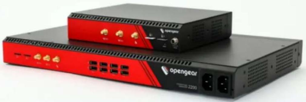
Two opengear networking devices, one black and one red, with ports and ventilation grilles (no visible text or symbols on the devices themselves)Contents
Copyright © 6
Safety & FCC Statement 7
About This User Guide...9
Installation And Connection 10
Power Connection 11
Dual AC Supply 13
Device Status LEDs 15
Connecting to the Network 17
Serial Connection 18
Cellular Connectivity 19
Reset and Erase 20
Initial System Configuration 21
Default Settings.... 22
Management Console Connection via CLI 24
Change the Root Password 25
Disable a Root User 27
MONITOR Menu 31
System Log 32
LLDP CDP Neighbors 33
Triggered Playbooks 34
ACCESS Menu 35
Local Terminal.... 36
Access Serial Ports 37
CONFIGURE Menu 40
Serial Ports 41
Local Management Consoles..45
Lighthouse Enrollment 47
Playbooks 49
PDUs .52
SNMP Alerts 54
SNMP Alerts System - Temperature, Authentication, Configuration 55
SNMP Alerts Power 58
SNMP Alerts Networking (Connection Status) 60
Network Connections 62
Network Interfaces 63
Dual SIM 64
Dual SIM Automatic Failover 70
Network Aggregates - Bonds and Bridges 76
Spanning Tree Protocol 82
IPsec Tunnels 85
Network Resilience 89
OOB Failover 90
IP Passthrough 91
User Management 92
Groups 93
Local Users 96
Remote Authentication 101
RemoteLocal for AAA Server 107
Local Password Policy 110
Services 115
HTTPS Certificate 116
Network Discovery Protocols 118
Routing 119
SSH 120
Unauthenticated SSH to Console Ports.122....
Syslog 128
Remote Syslog.130
Session Settings 135
Firewall .136
Firewall Management 137....
Interzone Polices 144
Services - Firewall 147
Date & Time.... 149
Time Zone 150
Manual Settings 151
Automatic Settings 152
System 153
Administration 155
Factory Reset 156
Reboot 157
System Upgrade 158
SNMP 159
SNMP Service 160
SNMP Alert Managers 161
Multiple SNMP Alert Managers.... 163
Advanced Options 166
Communicating With The Cellular Modem.... 167
OGCLI Guide....169
Docker 184
Cron 185
Initial Provisioning via USB Key 187
EULA and GPL...189.
UI Button Definitions...190
Copyright ©
Opengear Inc. 2020. All Rights Reserved.
Information in this document is subject to change without notice and does not represent a commitment on the part of Opengear. Opengear provides this document "as is," without warranty of any kind, expressed or implied, including, but not limited to, the implied warranties of fitness or merchantability for a particular purpose.
Opengear may make improvements and/or changes in this manual or in the product (s) and/or the program(s) described in this manual at any time. This product could include technical inaccuracies or typographical errors. Changes are periodically made to the information herein; these changes may be incorporated in new editions of the publication.
Safety & FCC Statement
Safety Statement
Please take care to follow the safety precautions below when installing and operating the OPERATIONS MANAGER:
- Do not remove the metal covers. There are no operator serviceable components inside. Opening or removing the cover may expose you to dangerous voltage which may cause fire or electric shock. Refer all service to Opengear qualified personnel.
- To avoid electric shock the power cord protective grounding conductor must be connected through to ground.
• Always pull on the plug, not the cable, when disconnecting the power cord from the socket.
Do not connect or disconnect the appliance during an electrical storm. Also use a surge suppressor or UPS to protect the equipment from transients.
FCC Warning Statement
This device complies with Part 15 of the FCC rules. Operation of this device is subject to the following conditions: (1) This device may not cause harmful interference, and (2) this device must accept any interference that may cause undesired operation.
!
Proper back-up systems and necessary safety devices should be utilized to protect against injury, death or property damage due to system failure. Such protection is the responsibility of the user.
SAFETY & FCC STATEMENT 7
This device is not approved for use as a life-support or medical system.
Any changes or modifications made to this device without the explicit approval or consent of Opengear will void Opengear of any liability or responsibility of injury or loss caused by any malfunction.
This equipment is for indoor use and all the communication wiring are limited to inside of the building.
About This User Guide
This user guide covers the Opengear Operation Manager products, including the OM2200 family of rack-mountable appliances (available with combinations of up to 48 serial ports and 24 Ethernet ports) and the OM1200 family of small form-factor appliances (available with combinations up to 8 serial and 8 Ethernet ports).
This manual is up to date for the 20.Q4 November 2020 firmware release. When using a minor release there may or may not be a specific version of the user guide for that release. The current Operations Manager user guide can always be found here.
Installation And Connection
This section describes how to install the appliance hardware and connect it to controlled devices.
Power Connection
OM2200 and some newer OM1200 have dual power inlets with auto failover built in. These power supplies each accept AC input voltage between 100 and 240 VAC with a frequency of 50 or 60Hz . The OM2224-24E-10G-L draws a maximum of 48W, while non-24E are less than 30W.
Two IEC AC power sockets are located on the power side of the metal case, and these IEC power inlets use conventional IEC AC power cords.
Note: Country specific IEC power cords are not included with OM2200s. OM1200s are shipped with a 12VDC to universal AC (multi-country clips) wall adapter.
See also "Dual AC Supply" on page 13 and "SNMP Alerts Power" on page 58.
| Operations Manager Platform (OM1200) Environmental And Power | |
| Power Draw < 25 Watts | |
| Operating conditions Temperature | 0~50C, Rel Humidity 5~90% |
| Cooling Passive | |
| Environmental Sensors Smart | Controller with multi-zone temperature sensors. |
| Auto-shutdown/re-boot on severe thermal events | |
| Power Draw Sensors Active | multi-zone power draw monitoring |
INSTALLATION AND CONNECTION 11
| Operations Manager Platform (OM2200) Environmental And Power | |
| Power Supply Dual AC or dual DC | |
| Power Draw 48 Watts for -24E, others <30W | |
| Operating conditions Temperature 0~50C, Rel Humidity 5~90% | |
| Cooling Passive | |
| Environmental Sensors Smart Controller with multi-zone temperature sensors | |
| Power Draw Sensors Active multi-zone power draw monitoring |
Dual AC Supply
Dual AC Supply can provide power redundancy for devices, especially those that may operate in harsher environments. A secondary power supply provides redundancy for the device if one PSU is unplugged or in the event of a failure.
LED Power Status Indicator
The power LED indicator requires no configuration and will display the dual power status on any Operations Manager device with a dual power supply.
| On a device with single PSU (power supply unit), a dual PSU device has power connected to two PSUs, the LED power status indicator should be green all times. | |
| OM 1200 | OM 2200 |
| If a dual PSU device has power connected on the PSU (power supply unit), the LED power status indicator is colored orange indicating that the unit has no redundancy in the event of a power failure. | |
| OM 1200 | OM 2200 |
| INSTALLATION AND CONNECTION 13 |
SNMP Alerts for Power-related Events
The System Voltage Range SNMP alert is triggered when there is a change in power status such as a system reboot or when the voltage on either power supply leaves or enters the configured range of the System Voltage alert.
SNMP Alert Configuration
The System Voltage Range SNMP alert is configured in the Configure > SNMP Alerts page, see "SNMP Alerts Power" on page 58.
Device Status LEDs
The LED states shown below are determined through infod status and config-server data. The config server holds a configurable threshold value for the Cell LED Amber / Green light, and modem enabled / disabled information.
| Status LEDs | |||||
| LED Condition | |||||
| LED Off | Amber Flashing | Amber Solid | Green Flashing | Green Solid | |
| Power Device is off. On a dual | power supply system: Only one PSU is connected. | On a single power supply system: power is connected. On a dual power supply system: Redundant power is connected. | |||
| Heartbeat Device has halted. | Device is booting. | Normal operation. | Device is halted. | ||
| Network □ □ □ | No active net-work con- nection | Device is fail-over starting. | Device is in failover. | Normal net-work con- nection is stopping or nor-mal network is up and failover is stopping. | Network is connected. |
| INSTALLATION AND CONNECTION | 15 |
| Status LEDs (continued). | |||||
| LED Condition | |||||
| LED Off | Amber Flashing | Amber Solid | Green Flashing | Green Solid | |
Cellular Interface | Cellular is not in use. | Cell is starting and signal is below threshold. The LED signal threshold config is set to 50%. | Cell is connected and signal is below threshold. The LED signal threshold config is set to 50%. | Cell is starting and signal is above, or equal to the threshold. | Cell is connected and signal is above, or equal to the threshold. |
IOIO Any serial | activ- | ity is received, on either console/usb console or device serial ports. | |||
Cloud / Internet | Not implemented. | ||||
Note: The amber LED signal threshold config is set to 50%. of normal signal strength.
For information on the setting of network and power alert thresholds, see:
"SNMP Alerts Networking (Connection Status)" on page 60
"SNMP Alerts Power" on page 58
INSTALLATION AND CONNECTION 16
Connecting to the Network
All Operations Manager products have two network connections labeled NET1 and NET2. In the OM2200, there are options for copper wiring (on a standard RJ-45 connector) and fiber (through a standard SFP module).
The network connections on the OM2200 are located on the serial port side of the unit. Connect the provided shielded CAT5 cable to the NET1 to a computer or into your network for initial configuration. By default NET1 and NET2 are enabled.
You can use either 10/100/1000BaseT over Cat5 or fiber-optical transceiver (1Gbps) in the SFP slot for NET1 or NET2 on OM2200 (non-10G) and OM1208-8E.
Serial Connection
The serial connections feature RS-232 with software selectable pin outs (Cisco straight -X2 or Cisco reversed -X1). Connect serial devices with the appropriate STP cables.
Cellular Connectivity
The Operations Manager products offer an optional global cellular LTE interface (models with -L suffix). The cellular interface is certified for global deployments with most carriers and provides a CAT12 LTE interface supporting most frequencies in use. To activate the cellular interface, you should contact your local cellular carrier and activate a data plan associated to the SIM installed.
For -L models, attach the 4G cellular antennas to the unit's SMA antenna sockets on the power face (or to the extension RF cables) before powering on. Insert the 2FF SIM card on the power face with the contact facing up. Use the left SIM socket first.
Installing A New SIM Card
Before installing a new SIM card, the OM device must first be powered down. This can be done by switching off the power supply and waiting until the device has shut-down. Install the new SIM card into its slot, then restart the device
Note: The device will not recognize the new SIM card unless a shut-down and restart is performed. The new SIM card will be read during start-up.
Reset and Erase
CONFIGURE > System > Reboot
The OPERATIONS MANAGER reboots with all settings (e.g. the assigned network IP address) preserved.
To reboot the unit:
Select CONFIGURE > System > Reboot.
To erase the unit:
Push the Erase button on the port-side panel twice with a bent paper clip while the unit is powered on.
This resets the appliance to its factory default settings. Any modified configuration information is erased. You will be prompted to log in and must enter the default administration username and administration password (Username: root Password: default). You will be required to change this password during the first log in.
Initial System Configuration
This section provides step-by-step instructions for the initial configuration of your OPERATIONS MANAGER.
By default, all interfaces are enabled. The unit can be managed via WebGUI or by command line interface (CLI).
- "Default Settings" on the next page
- "Management Console Connection via CLI" on page 24
- "Change the Root Password" on page 25
- "Disable a Root User" on page 27
• "Change Network Settings" on page 27 - For Configure Serial Ports (see "Serial Ports" on page 41)
Default Settings
The OPERATIONS MANAGER comes configured with a default static IP Address of 192.168.0.1 Subnet Mask 255.255.255.0.
The OM offers a WebGUI via web browser that supports HTML5.
- Type https://192.168.0.1 in the address bar. HTTPS is enabled by default.
- Enter the default username and password
Username: root
Password: default
- After the first successful log-in you will be required to change the root password.
- After log-in, the WebGUI is available. Check system details
- After log-in the WebGUI is available. Check system details in the top right-hand side of the WebGUI.
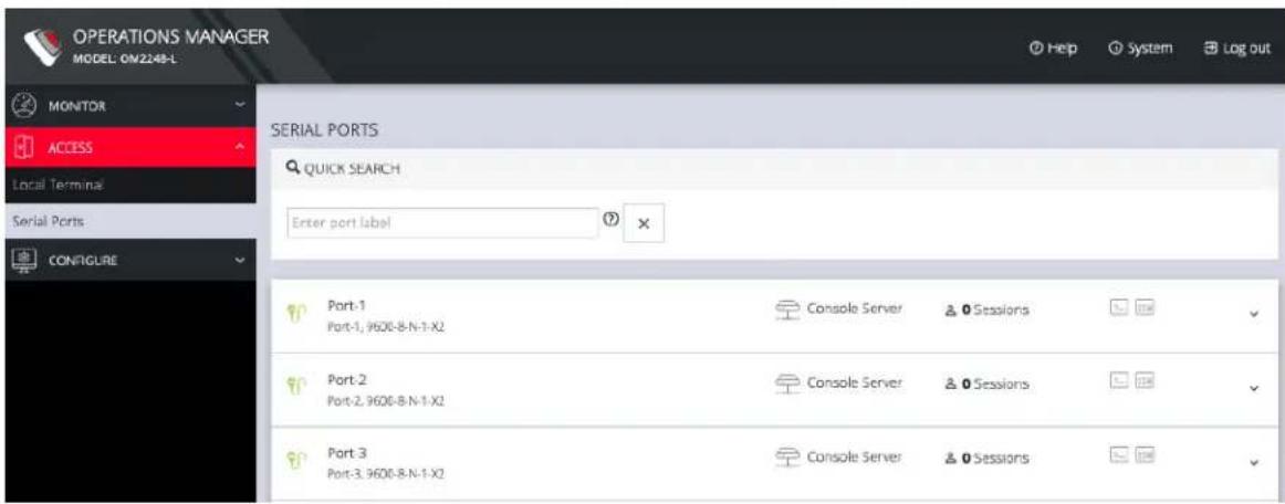
- In the Navigation Bar on the left side, navigate to the ACCESS > Serial Ports page. The Serial Ports page displays a list of all the serial devices, including the links to a Web Terminal or SSH connection for each.
text_image
OPERATIONS MANAGER MODEL: OM2248-L MONITOR ACCESS Local Terminals Serial Ports CONFIGURE SERIAL PORTS QUICK SEARCH Enter port label Port-1 Port-1, 9600-B-N-1-X2 Console Server ▲ Sessions Port-2 Port-2, 9600-B-N-1-X2 Console Server ▲ Sessions Port-3 Port-3, 9600-B-N-1-X2 Console Server ▲ SessionsThe WebUI can switch between Light or Dark mode by adjusting the toggle on the bottom left.

Light mode changes the user interface to display mostly light colors. This is the default UI setting. Dark mode changes the user interface to display mostly dark colors, reducing the light emitted by device screens.
The WebUI has three menu options on the upper right: Help, System, and Log out.
The Help menu contains a link to generate a Technical Support Report that can be used by Opengear Support for troubleshooting. It also contains a link to the latest Operations Manager User Manual.
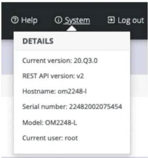
The System menu presents the Current version, REST API version, Hostname, Serial Number, Model, and Current user.
text_image
DETAILS Current version: 20.Q3.0 REST API version: v2 Hostname: om2248-l Serial number: 22482002075454 Model: OM2248-L Current user: rootManagement Console Connection via CLI
The Command Line Interface (CLI) is accessible using your preferred application to establish an SSH session. Open a CLI terminal on your desktop, then:
- Input the default IP Address of 192.168.0.1. SSH port 22 is enabled by default.
- When prompted, enter the log in and password in the CLI.
- After a successful log in, you'll see a command line prompt.
Accessing the WebGUI CLI Terminal
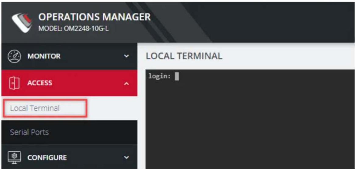
An alternative CLI terminal is provided within the WebGUI. To access this terminal, in the left-hand side Navigation Bar, navigate to the ACCESS > Local Terminal page. You will be required to submit your log-in credentials.
text_image
OPERATIONS MANAGER MODEL: OM2248-10G-L MONITOR ACCESS Local Terminal Serial Ports CONFIGURE LOCAL TERMINAL login:Change the Root Password
CONFIGURE > User Management > Local Users > Edit User
For security reasons, only the root user can initially log into the appliance. Upon initial log in the default password must be changed.
Tip: Other Users' passwords may be changed using the same procedure by selecting the User's account name under the Username heading.
To change the password at any time:
- Navigate to CONFIGURE > User Management > Local Users
- Click the Root user's Edit User icon below the Actions heading.
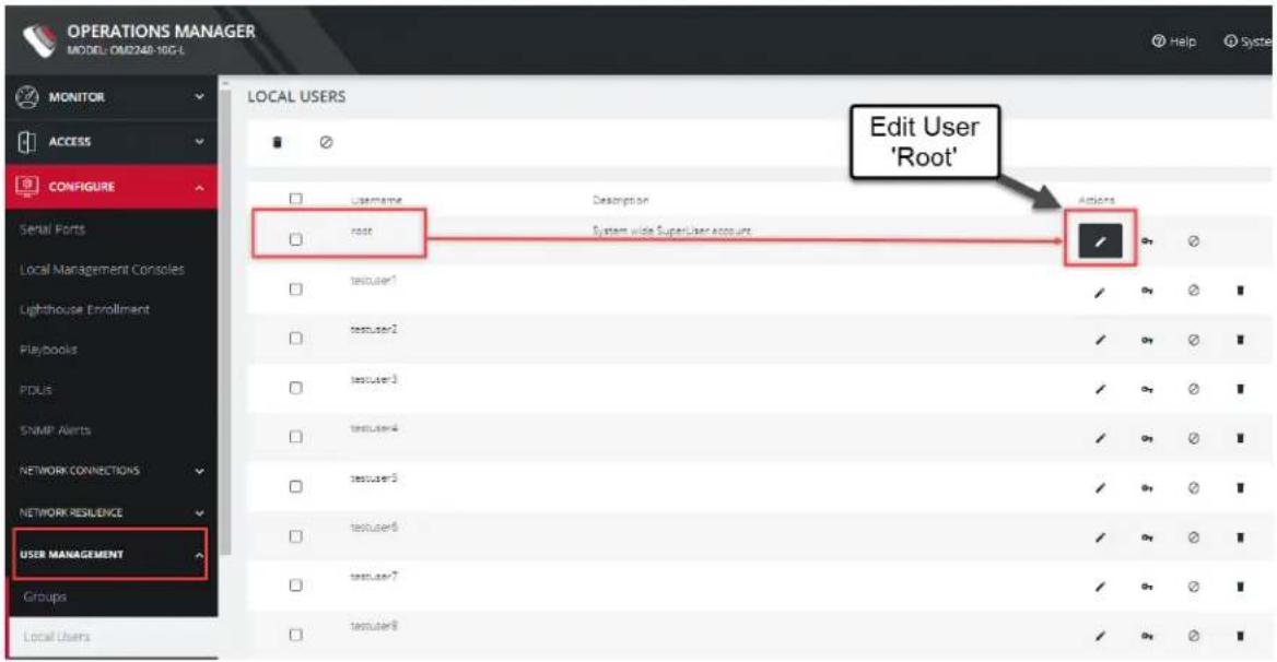
text_image
OPERATIONS MANAGER MODEL: OR2248-10G-L MONITOR ACCESS CONFIGURE LOCAL USERS Edit User 'Root' Serial Ports Local Management Consoles Lighthouse Enrollment Playbooks PDUS SNMP Alerts NETWORK CONNECTIONS NETWORK RESILIENCE USER MANAGEMENT Groups Local Users- In the Edit User page, if required, enter an optional description in the Description field. Enter a new password in the Password field and re-enter the password in the Confirm Password field.
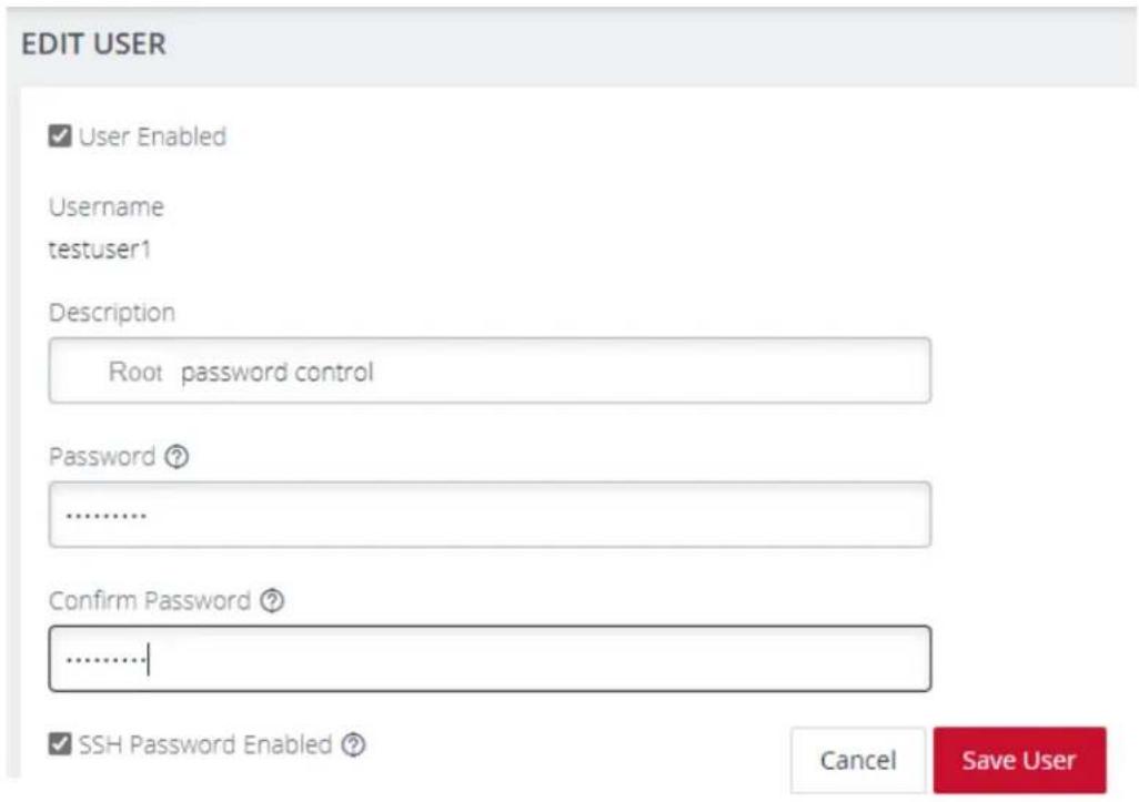
text_image
EDIT USER ✓ User Enabled Username testuser1 Description Root password control Password ? .......... Confirm Password ? .......... ✓ SSH Password Enabled ? Cancel Save User- Click Save User. A green banner confirms the password change has been saved.
Disable a Root User
CONFIGURE > User management > Local Users
To disable a root user:
Note: Before proceeding, make sure that another user exists that has the Administrator role or is in a group with the Administrator role. For information on creating, editing, and deleting users, see "Local Users" on page 96
- Navigate to CONFIGURE > User management > Local Users
- Click the Disable User button in the Actions section next to the root user.
- Click Yes in the Confirmation dialog.
To enable root user, log in with another user that has the Administrator role and click the Enable User button in the Actions section next to the root user.
Change Network Settings
CONFIGURE > Network Connections > Network Interfaces
The interface supports both IPv4 and IPv6 networks. The IP address of the unit can be setup for Static or DHCP. The following settings can be configured for network ports:
- IPv4, IPv6
• Static and/or DHCP - Enabling or disabling network interfaces
- Ethernet Media types
To add a new connection:
- Click CONFIGURE > Network Connections > Network Interfaces
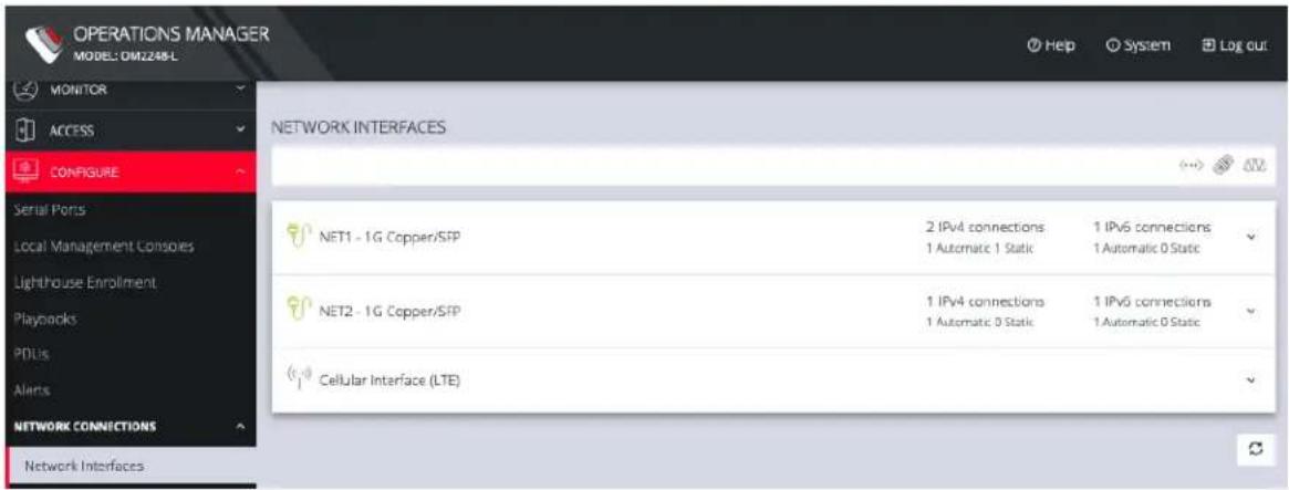
text_image
OPERATIONS MANAGER MODEL: DM2248-L MONITOR ACCESS CONFIGURE NETWORK INTERFACES NET1 - 1G Copper/SFP 2 IPv4 connections 1 Automatic 1 Static 1 IPv6 connections 1 Automatic 0 Static NET2 - 1G Copper/SFP 1 IPv4 connections 1 Automatic 0 Static 1 IPv6 connections 1 Automatic 0 Static Cellular Interface (LTE)- Click the expand arrow to the right of the desired interface to view its details.
- Click the plus icon to open the New Connection page.

text_image
OPERATIONS MANAGER MODEL:OM2284 MONITOR ACCESS CONFIGURE Serial Ports Local Management Consistency Lighthouse Enrollment Playbooks POUs AMTS NETWORK CONNECTIONS Network Interfaces IPsec Funnels NETWORK RESLENCE USER MANAGEMENT Groups Local Users Remote Authentication SERVICES FIREWALL DATE & TIME SYSTEM SNMP NEW CONNECTION CONNECTION DETAILS Interface NET1 - 1G Copper/SFP The interface for connection Connection Type IPv4 Static The type of connection to create IPv4 STATIC IPv4 Address The IPv4 address to set for this connection IPv4 Network Mask The network mask for this connection Gateway The address of the local network gateway Primary DNS Server The address of the primary DNS server Secondary DNS Server The address of the secondary DNS server Cancel Apply- Select the Interface and Connection Type for your new connection.
- The form on the bottom part of the page will change based on the Connection Type you choose. Enter the necessary information and click Apply.
To disable or delete interfaces, use the controls on the expanded section on the CONFIGURE > Network Connections > Network Interfaces page.
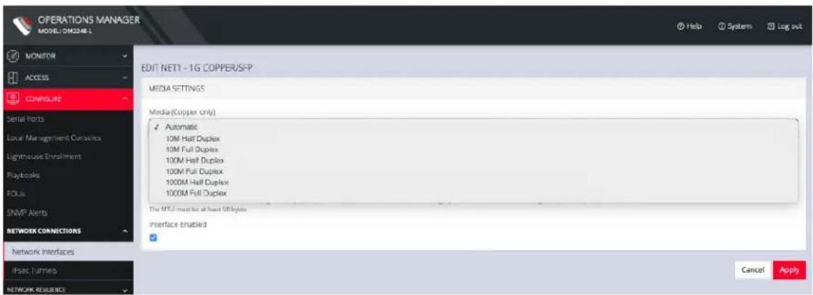
Note: If you experience packet loss or poor network performance with the default auto-negotiation setting, try changing the Ethernet Media settings on the OPERATIONS MANAGER and the device it is connected to. In most cases, select 100 megabits, full duplex. Make sure both sides are set identically.
To change the Ethernet Media Type:
- Click CONFIGURE > Network Connections > Network Interfaces
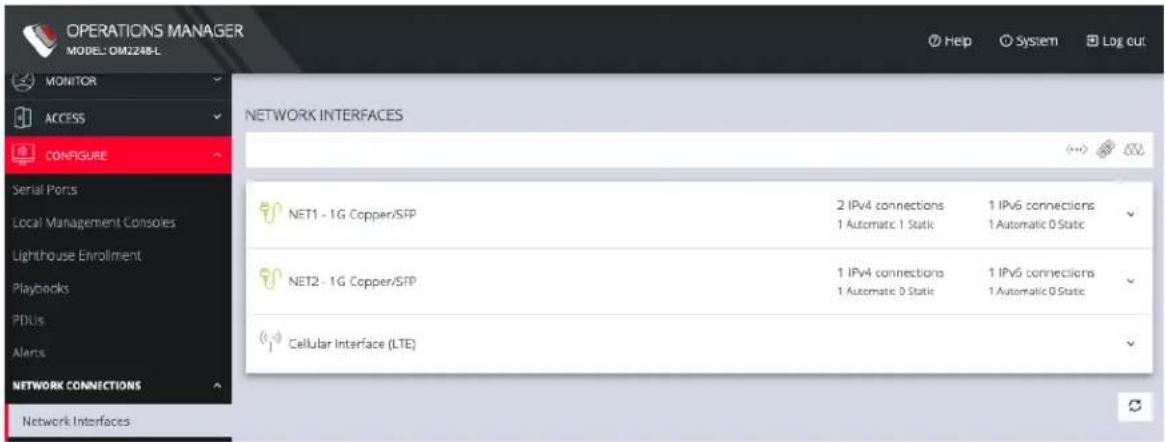
text_image
OPERATIONS MANAGER MODEL: DM2248-L MONITOR ACCESS CONFIGURE NETWORK INTERFACES NET1 - 1G Copper/SFP 2 IPv4 connections 1 Automatic 1 Static 1 IPv6 connections 1 Automatic 0 Static NET2 - 1G Copper/SFP 1 IPv4 connections 1 Automatic 0 Static 1 IPv6 connections 1 Automatic 0 Static Cellular Interface (LTE)- Click the expand arrow to the right of the interface you wish to modify.
3. Click Enabled Automatic.
text_image
OPERATIONS MANAGER MODEL: DM2248 L EDIT NET1 - 1G COPPER/SFP MEDIA SETTINGS Media (Copper only) Automatic 10M Half Duplex 10M Full Duplex 100M Half Duplex 100M Full Duplex 1000M Half Duplex 1000M Full Duplex The MTU must be at least 50 bytes. Interface enabled Network Interfaces IPSEC Turmets NETWORK RESOURCES Cancel Apply- Change the Media Setting as needed and click Apply.
The MONITOR Menu is a relatively short section comprising only three topics.
- System Log
• Details of the system activity log, access and communications events with the server and with attached serial, network and power devices.
• LLDP/CDP Neighbors
- Details of the LLDP/CDP Neighbors that are displayed when enabled for a connection.
• Triggered Playbooks
• Monitoring current Playbooks, and applying filters to view any Playbooks that have been triggered.
System Log
MONITOR > System Log
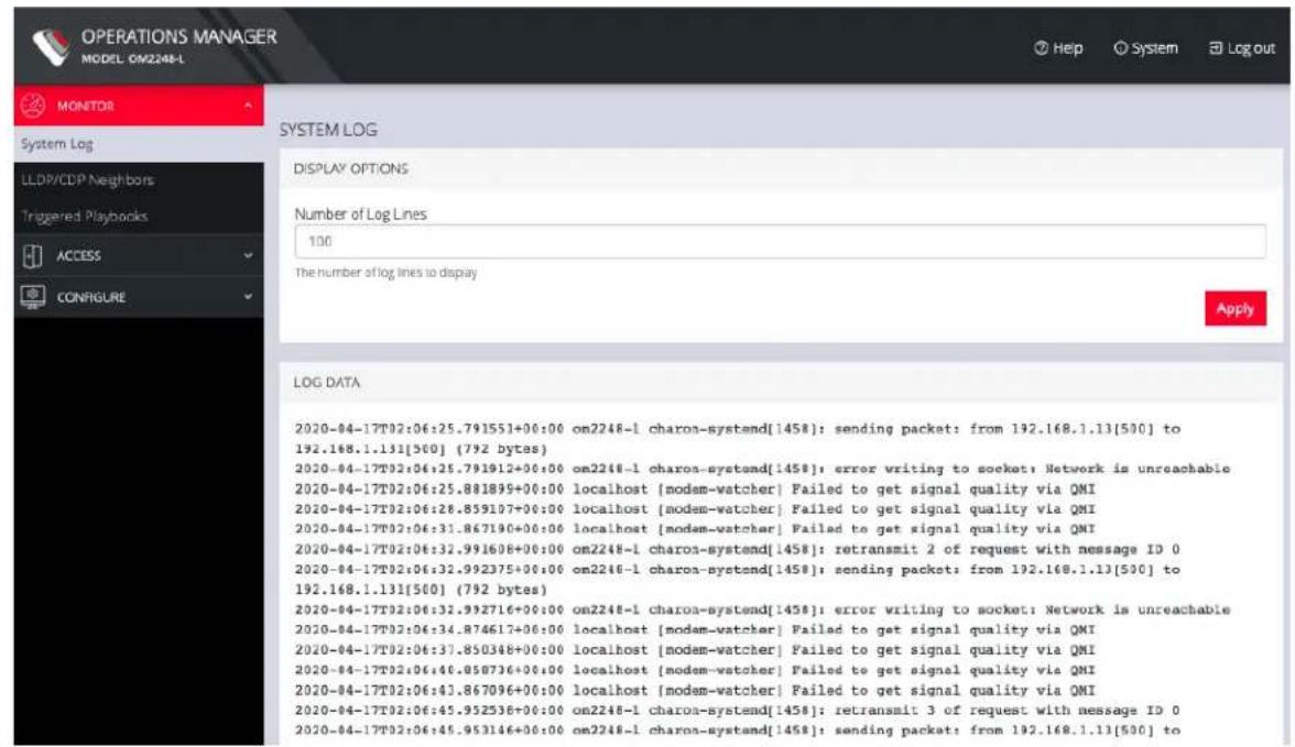
The OPERATIONS MANAGER maintains a log of system activity, access and communications events with the server and with attached serial, network and power devices.
To view the System Log, click MONITOR > System Log.
text_image
OPERATIONS MANAGER MODEL OM2248-L MONITOR System Log LLDP/CDP Neighbors Triggered Playbooks ACCESS CONFIGURE SYSTEM LOG DISPLAY OPTIONS Number of Log Lines 100 The number of log lines to display Apply LOG DATA 2020-04-17T02:06:25.791551+00:00 on2248-1 charo-systemd[1458]: sending packet: from 192.168.1.13[500] to 192.168.1.131[500] (792 bytes) 2020-04-17T02:06:25.791912+00:00 on2248-1 charo-systemd[1458]: error writing to socket: Network is unreachable 2020-04-17T02:06:25.881899+00:00 localhost [modem-watcher] Failed to get signal quality via QMI 2020-04-17T02:06:28.859107+00:00 localhost [modem-watcher] Failed to get signal quality via QMI 2020-04-17T02:06:31.867190+00:00 localhost [modem-watcher] Failed to get signal quality via QMI 2020-04-17T02:06:32.991608+00:00 on2248-1 charo-systemd[1458]: retransmit 2 of request with message ID 0 2020-04-17T02:06:32.992375+00:00 on2248-1 charo-systemd[1458]: sending packet: from 192.168.1.13[500] to 192.168.1.131[500] (792 bytes) 2020-04-17T02:06:32.992716+00:00 on2248-1 charo-systemd[1458]: error writing to socket: Network is unreachable 2020-04-17T02:06:34.874617+00:00 localhost [modem-watcher] Failed to get signal quality via QMI 2020-04-17T02:06:37.850348+00:00 localhost [modem-watcher] Failed to get signal quality via QMI 2020-04-17T02:06:46.858736+00:00 localhost [modem-watcher] Failed to get signal quality via QMI 2020-04-17T02:06:43.867096+00:00 localhost [modem-watcher] Failed to get signal quality via QMI 2020-04-17T02:06:45.952536+00:00 on2248-1 charo-systemd[1458]: retransmit 3 of request with message ID 0 2020-04-17T02:06:45.953146+00:00 on2248-1 charo-systemd[1458]: sending packet: from 192.168.1.13[500] toThe System Log page lets you change the Number of Log Lines displayed on the screen. The newest items appear on the bottom of the list. Click the Refresh button on the bottom right to see the latest entries.
MONITOR MENU 32
LLDP CDP Neighbors
MONITOR > LLDP/CDP Neighbors
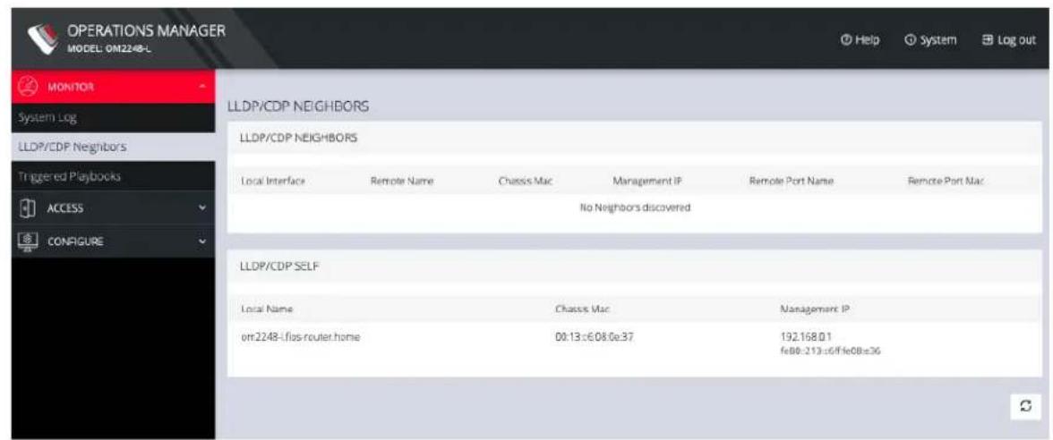
The OPERATIONS MANAGER displays LLDP/CDP Neighbors when enabled for a connection. See CONFIGURE > SERVICES > Network Discovery Protocols to enable/disable.
text_image
OPERATIONS MANAGER MODEL: 0M2248-L MONITOR System Log LLDP/CDP Neighbors Triggered Playbooks ACCESS CONFIGURE LLDP/CDP NEIGHBORS LLDP/CDP NEIGHBORS Local Interface Remote Name Chassis Mac Management IP Remote Port Name Remote Port Mac No Neighbors discovered LLDP/CDP SELF Local Name Chassis Mac Management IP on:2248-Ifos-router.home 00:13:e608:e37 192.168.01 fe80-213:e6/ffe08:e36Triggered Playbooks
MONITOR > Triggered Playbooks
For information on creating Playbooks, see Playbooks.
To monitor current Playbooks, click on Monitor > Playbooks. Choose the time period if desired, and filter by Name of Playlist to view any that have been triggered.
ACCESS Menu
The ACCESS menu lets you access the OPERATIONS MANAGER via a built-in Web Terminal. It also provides SSH and Web Terminal access to specific ports.
Local Terminal
ACCESS > Local Terminal
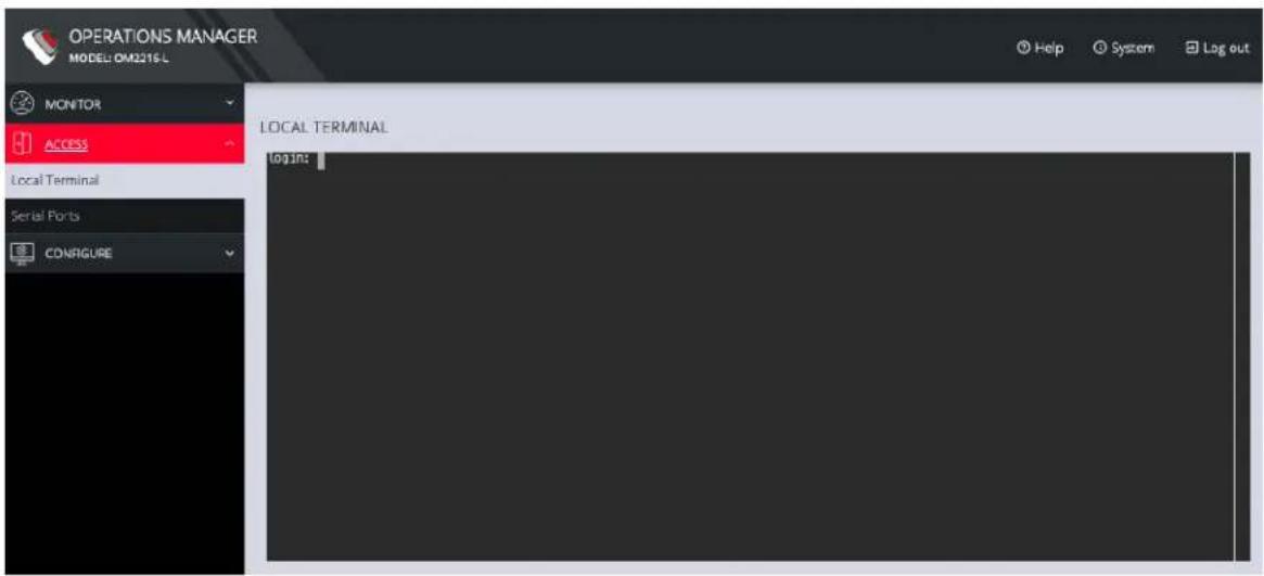
The OPERATIONS MANAGER includes a web-based terminal. To access this bash shell instance:
- Select ACCESS > Local Terminal.
text_image
OPERATIONS MANAGER MODEL: DM2216-L MONITOR ACCESS LOCAL TERMINAL LOG IN: Serial Ports CONFIGURE LOCAL TERMINAL Log out Help System Log out- At the log in prompt, enter a username and press Return.
- At the password prompt, enter a password and press Return.
- A bash shell prompt appears.
This shell supports most standard bash commands and also supports copy-and-paste to and from the terminal.
To close a terminal session, close the tab, or type exit in the Web Terminal window. The session will timeout after 60 seconds.
Access Serial Ports
ACCESS > Serial Ports
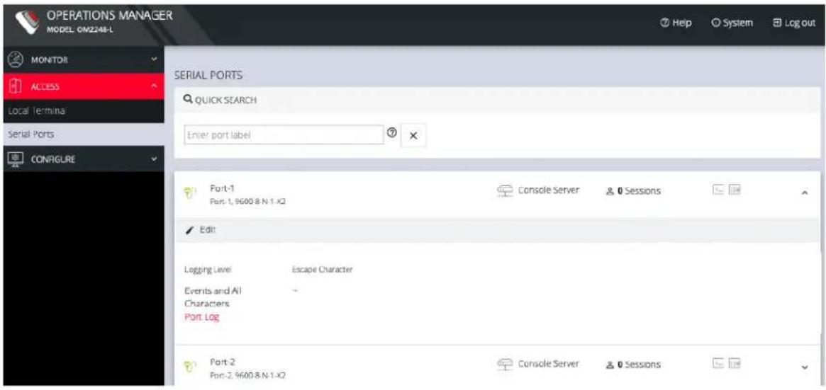
The ACCESS > Serial Ports page allows you to quickly locate and access specific ports via Web Terminal or SSH. Click the expand arrow to the right of the port to see these options.

text_image
OPERATIONS MANAGER MODEL OM2248-L MONITOR ACCESS Local Terminal Serial Ports CONAGLRE SERIAL PORTS QUICK SEARCH Enter port label Port-1 Port-1, 9600-8-N-1-X2 Console Server 0 Sessions Edit Logging Level Escape Character Events and All Characters Port Log Port-2 Port-2, 9600-8-N-1-X2 Console Server 0 SessionsQuick Search
To find a specific port by its port label, use the Quick Search form on the top of the ACCESS > Serial Ports page. Ports are given default numbered labels. You can set the port label for a given serial port under CONFIGURE > Serial Ports. Click the edit button under Actions to open the EDIT SERIAL PORT page.
Access Using Web Terminal or SSH
To access the console port via the Web Terminal or SSH:
ACCESS MENU 37

opengear
- Locate the particular port on the ACCESS > Serial Ports page and click the expand arrow.
-
Click the Web Terminal or SSH link for the particular port.
-
Choosing Web Terminal opens a new browser tab with the terminal.
- Choosing SSH opens an application you have previously associated with SSH connections from your browser.
Note: Serial port logging is disabled by default. Control the logging level for each serial port by changing Logging Settings in Configure > Serial Ports > Edit page.
LOGGING SETTINGS
Logging Level
√ Logging Disabled Events Only Events and Received Characters Events and All Characters
The log will appear via the Port Log link on the Serial Ports expanded page.
text_image
OPERATIONS MANAGER MODEL: CM2248-L MONITOR ACCESS Local Terminal Serial Ports CONFIGURE SERIAL PORTS QUICK SEARCH Enter port label Port-1 Port-1, 9600.8 N-1-X2 Console Server Sessions Edit Logging Level Escape Character Events and All Characters Port Log Port-2 Port-2, 9600.8 N-1-X2 Console Server SessionsCONFIGURE Menu
This section provides step-by-step instructions for the menu items under the CONFIGURE menu.
Serial Ports
CONFIGURE > Serial Ports
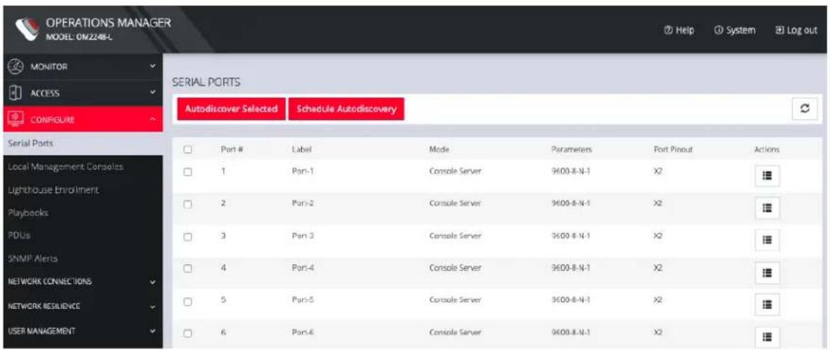
Click CONFIGURE > Serial Ports. A list of serial ports appears.
text_image
OPERATIONS MANAGER MODEL: OM2248-L MONITOR ACCESS CONFIGURE SERIAL PORTS Autodiscover Selected Schedule Autodiscovery Serial Ports Local Management Consoles Lighthouse Enrollment Playbooks PDUs SNMP Alerts NETWORK CONNECTIONS NETWORK RESILIENCE USER MANAGEMENT Port # Label Mode Parameters Port Pinout Actions 1 Port-1 Console Server 9600-8-N-1 X2 2 Port-2 Console Server 9600-8-N-1 X2 3 Port-3 Console Server 9600-8-N-1 X2 4 Port-4 Console Server 9600-8-N-1 X2 5 Port-5 Console Server 9600-8-N-1 X2 6 Port-6 Console Server 9600-8-N-1 X2This page lets you select serial ports and Autodiscover Selected ports.
You can Schedule Autodiscover by clicking the button. This opens a page that allows you to select the ports and specify a time and period for port detection to occur.
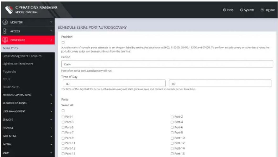
text_image
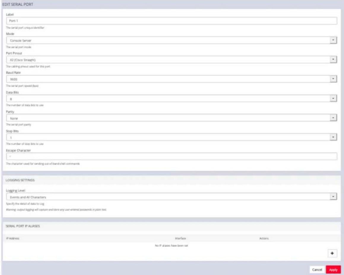
OPERATIONS MANAGER MODEL CM2248-L MONITOR ACCESS CONFIGURE Serial Ports Local Management Consoles Lighthouse Enrollment Playbooks PDUs SNMP Alerts NETWORK CONNECTIONS NETWORK RESILIENCE USER MANAGEMENT SERVICES FIREWALL DATE & TIME SYSTEM SNMP SCHEDULE SERIAL PORT AUTODISCOVERY Enabled Autodicovery of console ports attempts to set the port label by setting the baud rate to 9600, 115260, 38400, 15230 and 57600. To perform autodiscovery or other baud rates the port, discovery script can be manually run from the terminal. Period Daily How often serial port autodiscovery will run. Time of Day 00 00 The time of the day that the serial port autodiscovery will start given as hour and minute in console server local time. Ports Select All Port-1 Port-2 Port-3 Port-4 Port-5 Port-6 Port-7 Port-8 Port-9 Port-10 Port-11 Port-12 Port-13 Port-14 Port-15 Port-16From the Configure > Serial Ports page, click the Edit Serial Port button under Actions next to the Serial Port you wish to configure. The Edit Serial Port page opens.
text_image
EDIT SERIAL PORT Label Port-1 The serial port unique identifier Mode Console Server The serial port mode Port Pinout X2 (Cisco Straight) The cabling pinout used for this port Baud Rate 9600 The serial port speed (bits) Data Bits 8 The number of data bits to use Parity None The serial port party Stop Bits 1 The number of stop bits to use Escape Character The character used for sending out-of-band shell comments LOGGING SETTINGS Logging Level Events and All Characters Specify the detail of data to Log Warning output logging will capture and store any user-entered passwords in plain text. SERIAL PORT IP ALIASES IP Address Interface Actions No IP aliases have been set Cancel ApplyThe Edit Serial Port page lets you configure the serial port's:
- Label: This can be used to locate this port using the Quick Search form on the ACCESS > Serial Ports page.
• Mode: Disabled or Console Server
• Pin out: X1 Cisco Rolled or X2 Cisco Straight
• Baud Rate: 50 to 230,400 bps
• Data Bits: 5, 6, 7, 8 - Parity: None, Odd, Even, Mark, Space
- Stop Bits: 1, 1.5, 2
CONFIGURE MENU 43

opengear
- Logging Levels
- Serial Port Aliases
Local Management Consoles
CONFIGURE > Local Management Consoles
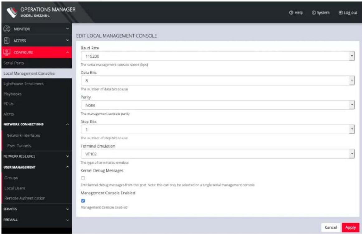
You can edit settings or disable the local RJ45 serial console (Cisco straight -X2 pinout) and the USB serial console (needs user supplied micro-USB to USB-A cable).
To edit the settings of a local management console:
- Click CONFIGURE > Local Management Consoles.
- Click on the Edit Management Console Port button under Actions next to the console you wish to disable.
text_image
OPERATIONS MANAGER MODEL: OM2248-L MONITOR ACCESS CONFIGURE Serial Ports Local Management Consoles Lighthouse Enrollment Playbooks PDUs Alerts NETWORK CONNECTIONS Network Interfaces IPsec Tunnets NETWORK RESILIENCE USER MANAGEMENT Groups Local Users Remote Authentication SERVICES FIREWALL EDIT LOCAL MANAGEMENT CONSOLE Baud Rate 115200 The serial management console speed (bps) Data Bits 8 The number of data bits to use Parity None The management console parity Stop Bits 1 The number of step bits to use Terminal Emulation VT102 The type of terminal to emulate Kernel Debug Messages ☐ Emit kernel debug messages from this port. Note: this can only be selected on a single serial management console Management Console Enabled ✓ Management Console Enabled Cancel ApplyCONFIGURE MENU 45
-
The Edit Local Management Console page lets you control:
-
Baud Rate
- Data Bits
- Parity
- Stop Bits
• Terminal Emulation - Enable or disable Kernel Debug Messages
- Enable or disable the selected Management Console
Note: Enabling Kernel Debug Messages can only be applied to a single serial management console.
To disable a local management console, click CONFIGURE > Local Management Consoles. Click on the Disable Management Console Port button under Actions next to the console you wish to disable.
Lighthouse Enrollment
CONFIGURE > Lighthouse Enrollment
Opengear appliances can be enrolled into a Lighthouse instance, providing centralized access to console ports, NetOps Automation, and central configuration of Opengear devices.
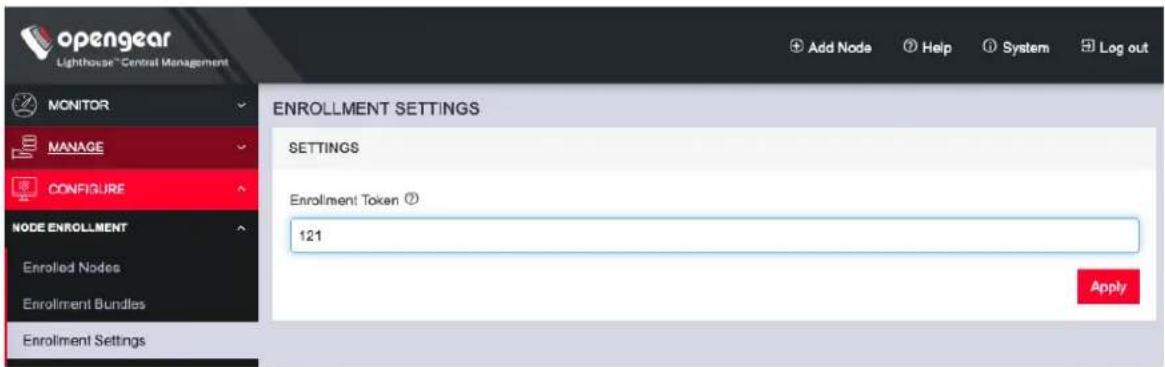
To enroll your OPERATIONS MANAGER to a Lighthouse instance, you must have Lighthouse installed and have an enrollment token set in Lighthouse.
To set an enrollment token in Lighthouse, click on CONFIGURE >
NODE ENROLLMENT > Enrollment Settings page, and enter an Enrollment Token.
text_image
opengear Lighthouse "Central Management MONITOR MANAGE CONFIGURE NODE ENROLLMENT Enrolled Nodes Enrolment Bundles Enrolment Settings ENROLLMENT SETTINGS SETTINGS Enrolment Token ? 121 ApplyTo enroll your OPERATIONS MANAGER in this Lighthouse instance:
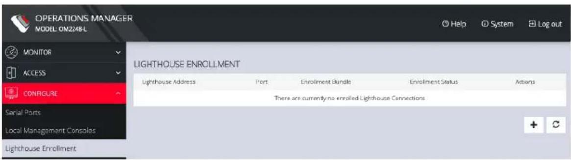
- Click CONFIGURE > Lighthouse Enrollment.
text_image
OPERATIONS MANAGER MODEL: ON2248-L MONITOR ACCESS CONFIGURE Serial Ports Local Management Consoles Lighthouse Enrollment LIGHHOUSE ENROLLMENT Lighthouse Address Port Enrolment Bundle Enrolment Status Actions There are currently no enrolled Lighthouse ConnectionsCONFIGURE MENU 47
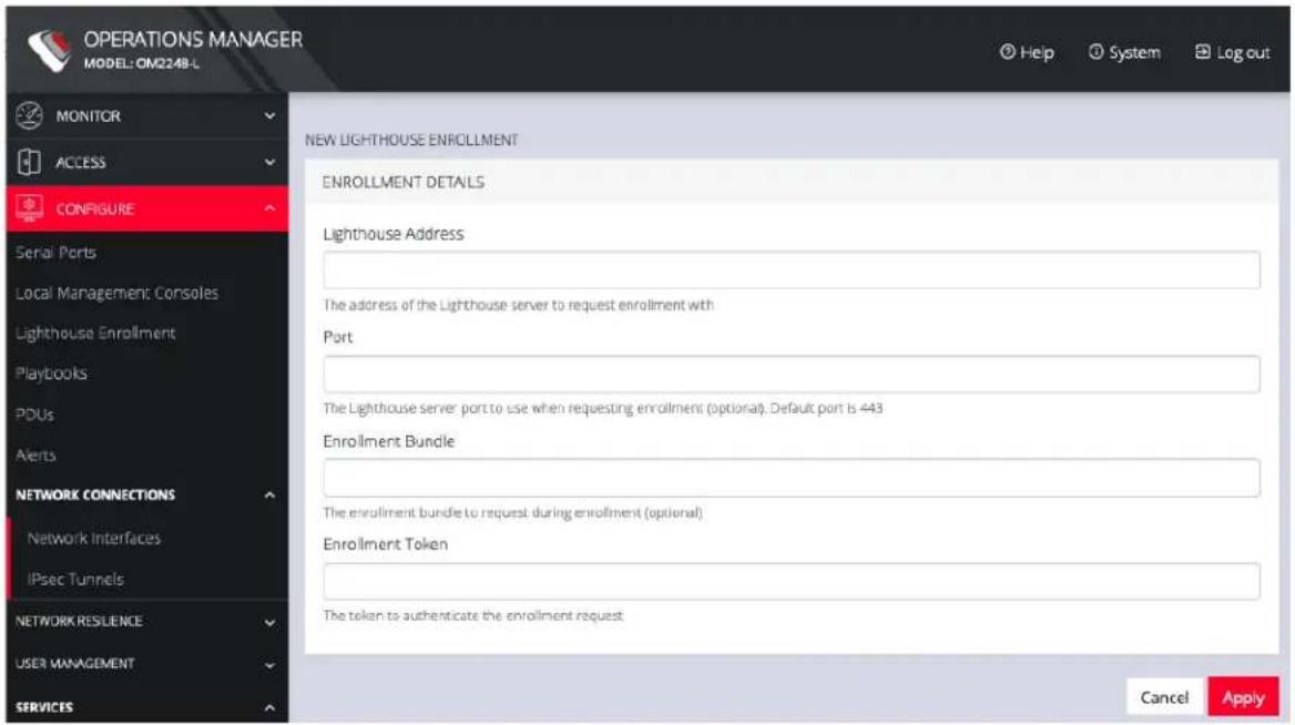
- Click on the Add Lighthouse Enrollment button on the bottom right. The New Lighthouse Enrollment page opens.
text_image
OPERATIONS MANAGER MODEL:OM2248-L MONITOR ACCESS CONFIGURE Serial Ports Local Management Consoles Lighthouse Enrollment Playbooks PDUs Alerts NETWORK CONNECTIONS Network Interfaces IPsec Tunnels NETWORK RESILENCE USER MANAGEMENT SERVICES NEW LIGHTHOUSE ENROLLMENT ENROLLMENT DETAILS Lighthouse Address The address of the Lighthouse server to request enrollment with Port The Lighthouse server port to use when requesting enrollment (optional). Default port is 443 Enrollment Bundle The enrollment bundle to request during enrollment (optional) Enrollment Token The token to authenticate the enrollment request Cancel Apply- Enter the IP address or fully qualified domain name of the Lighthouse instance and the Enrollment Token you created in Lighthouse. Optionally enter a Port and an Enrollment Bundle (see the Lighthouse User Guide for more information).
- Click Apply.
Note: Enrollment can also be done directly via Lighthouse using the Add Node function. See the Lighthouse User Guide for more instructions on enrolling Opengear devices into Lighthouse.
Playbooks
CONFIGURE > Playbooks
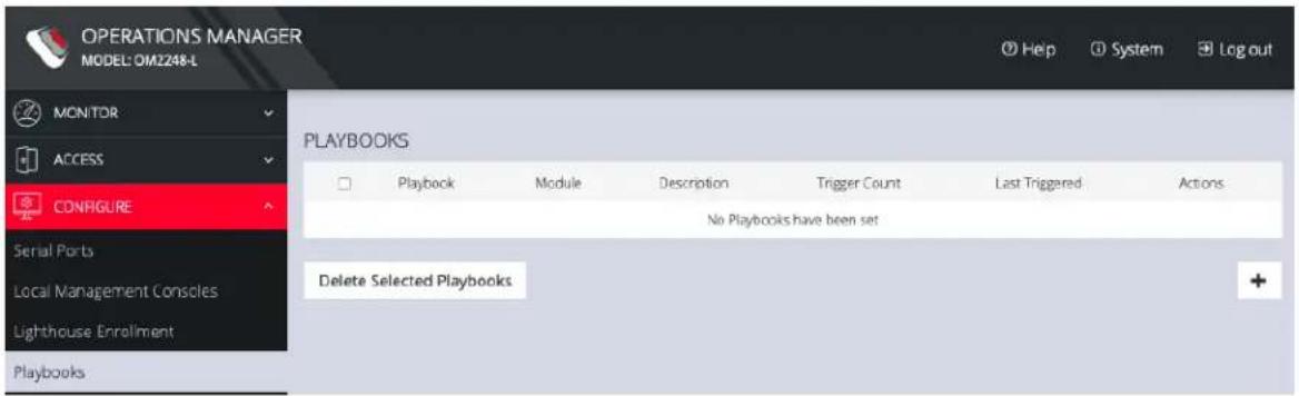
Playbooks are configurable systems that periodically check if a Trigger condition has been met. They can be configured to perform a one or more specified Reaction. To create a new Playbook, select Configure > Playbooks.
text_image
OPERATIONS MANAGER MODEL: OM2248-L MONITOR ACCESS CONFIGURE Serial Ports Local Management Consoles Lighthouse Enrollment Playbooks PLAYBOOKS Playbook Module Description Trigger Count Last Triggered Actions No Playbooks have been set Delete Selected PlaybooksClick the Plus button to create a new Playbook.
text_image
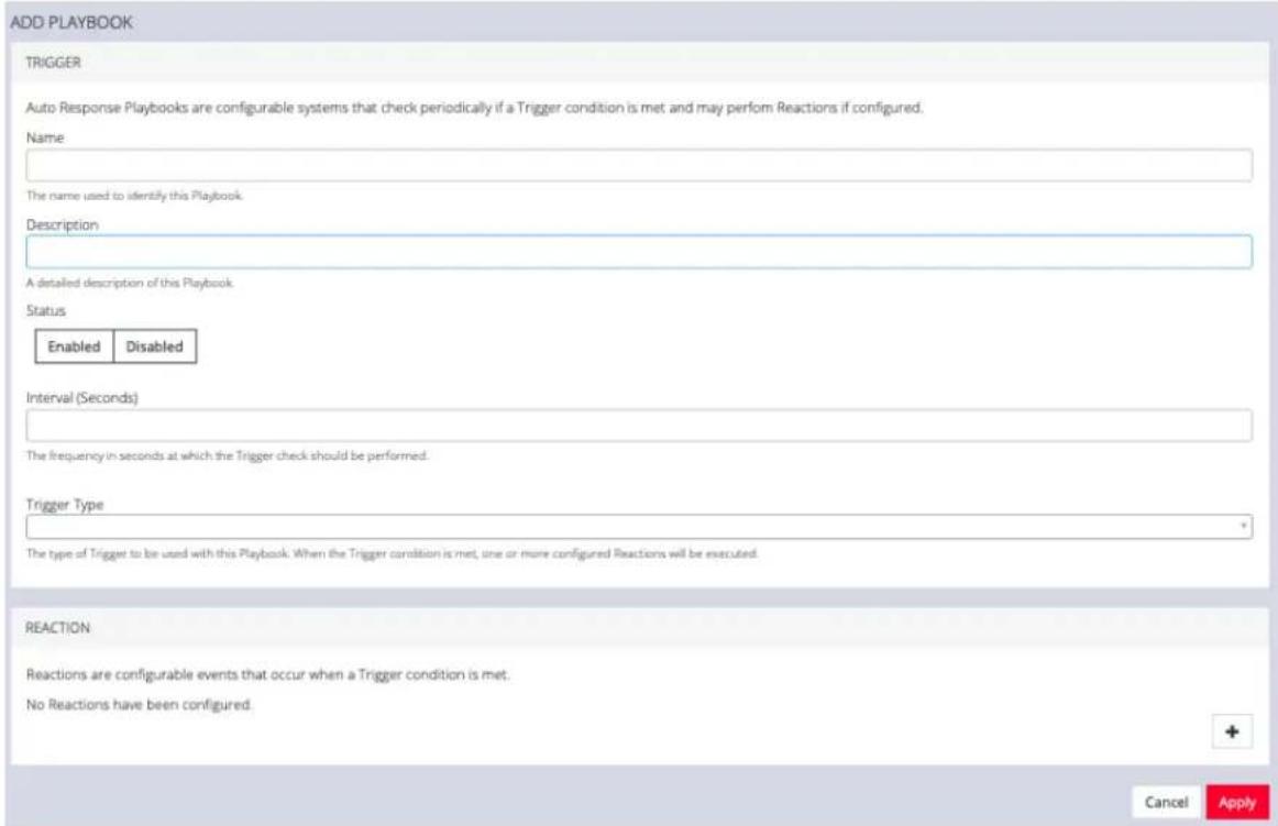
ADD PLAYBOOK TRIGGER Auto Response Playbooks are configurable systems that check periodically if a Trigger condition is met and may perform Reactions if configured. Name The name used to identify this Playbook. Description A detailed description of this Playbook. Status Enabled Disabled Interval (Seconds) The frequency in seconds at which the Trigger check should be performed. Trigger Type The type of Trigger to be used with this Playbook. When the Trigger condition is met, one or more configured Reactions will be executed. REACTION Reactions are configurable events that occur when a Trigger condition is met. No Reactions have been configured. Cancel Apply- Enter a Name for the Playbook.
- Add a Description.
- Select Enabled to activate the Playbook after you have created it.
- Enter an Interval in seconds to control the frequency that the Trigger will be checked.
- Choose the type of Trigger to use from the Trigger Type drop down.
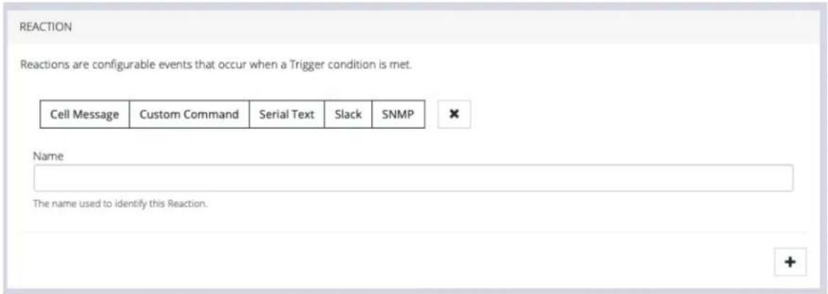
- In the Reaction section, click the Plus and click on specific Reactions for this Playbook.
text_image
REACTION Reactions are configurable events that occur when a Trigger condition is met. Cell Message Custom Command Serial Text Slack SNMP Name The name used to identify this Reaction.Clicking on each Reaction opens a custom screen to provide necessary information. When you are finished, click Apply.
After you have created Playbooks, you can Edit or Delete them from the Configure > Playbooks page.
To monitor current Playbooks, click on Monitor > Playbooks. Choose the time period if desired and filter by Name of Playlist to view any that have been triggered.
PDUs
CONFIGURE > PDUs
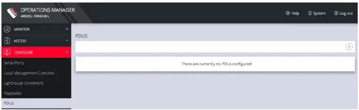
One or more Power Distribution Units (PDUs), both Local and Remote can be monitored. To add information for a PDU, select Configure > PDUs.
text_image
OPERATIONS MANAGER MODEL: OM2248 L MONITOR ACCESS CONFIGURE Serial Ports Local Management Consoles Lighthouse Enrollment Playbooks PDUs PDUS There are currently no PDUs configuredClick the Plus button to configure a new PDU.
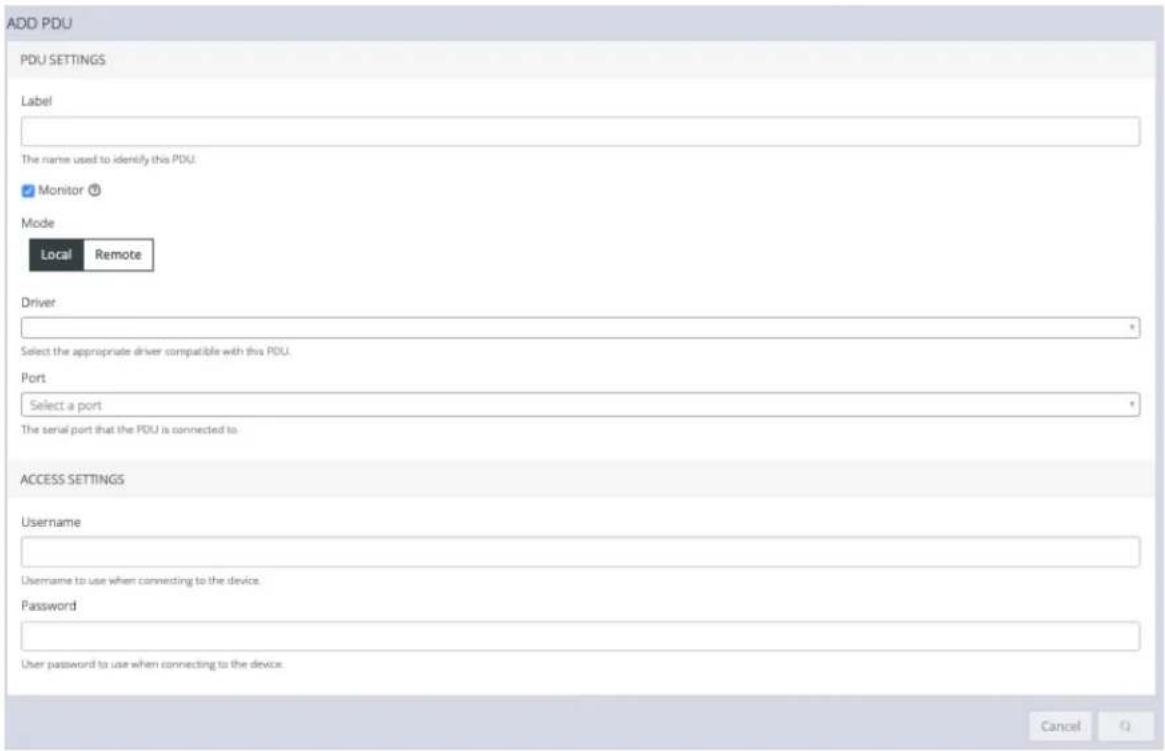
text_image
ADD PDU PDU SETTINGS Label The name used to identify this PDU. Monitor Mode Local Remote Driver Select the appropriate driver compatible with this PDU. Port Select a port The serial port that the PDU is connected to. ACCESS SETTINGS Username Username to use when connecting to the device. Password User password to use when connecting to the device. CancelCONFIGURE MENU 52

opengear
- Enter a Label for this PDU.
- Select the Monitor checkbox.
- Choose Local or Remote.
- Select the appropriate Driver from the drop-down list.
- Select the Port.
- Add a Description.
-
When you are finished, click Apply.
-
Under Access Settings, enter a Username and Password to use when connecting to the device.
After you have created PDUs, you can Edit or Delete them from the Configure > PDUs page.
SNMP Alerts
CONFIGURE > SNMP Alerts > System/Power/Networking
Tip: For more detailed information about configuring SNMP Alerts see the individual topic pages that follow.
On the CONFIGURE > SNMP Alerts page; SNMP Alert Managers can be added or deleted under SNMP > SNMP Alert Managers, for the following:
- System: Covers notification for the following causes.
- Authentication: Notifies when a user attempts to log in via SSH, REST API, Web UI, or the device's serial ports. An alert is sent regardless of whether the log in has succeeded or failed.
- Configuration: For changes that occur to the system configuration.
-
System Temperature: When temperature SNMP alerts are enabled, network operators are immediately notified should the system begin operating outside user-defined tolerances.
-
Power: When voltage SNMP alerts are enabled, network operators are immediately notified should the PSU begin operating outside design tolerances. See "SNMP Alerts Power" on page 58 for further information.
- Networking (Cell Signal Strength): Be notified when cell signal strength leaves or re-enters the selected range, or when the network link state changes. A slider adjusts the upper and lower signal strength.
Tip: Manage the SNMP settings on the CONFIGURE > SNMP > SNMP Alert Managers page.
SNMP Alerts System - Temperature, Authentication, Configuration
Temperature
CONFIGURE > SNMP Alerts > System > System Temperature
It is essential to ensure that the system is operating within its design temperature as premature aging of the component can occur if the device is excessively hot during operation. This can lead to component failure and ultimately result in RMA.
When temperature SNMP alerts are enabled (Alerting), network operators are immediately notified (subject to network connectivity and latency) should the PSU begin operating outside user-defined temperature tolerances.
System generated SNMP Alerts send SNMP traps to a remote SNMP manager which alerts the user of temperature events.
Tip: The OM device can send network, power and system events to the remote SNMP manager.
Configure SNMP System Temperature Alerts
Configure > SNMP Alerts > System > System Temperature
The System Temperature Range alert reports the system temperature (measured at System Temperature 1 and System Temperature 2 sensors) and sends an alert when the system temperature leaves or enters the user-configured temperature range.

opengear
- Navigate to Configure > SNMP Alerts > System > System Temperature.
- Click on the Alerting button to activate the function, this also activates the user-defined range sliders.
Note: The Not Alerting button de-activates the function and temperature alerts will be stopped until activated again.
- Click+Drag the temperature range limiters to the required upper and lower limits.
- Click Apply. The Details Saved banner confirms your settings.
SYSTEM TEMPERATURE
A temperature notification will be sent when any of the temperature sensors leaves or re-enters the specified range.
Alerting
Not Alerting
Temperature Range
50
99
Degrees Celsius
\~ 122 - 210 Degrees Fahrenheit
Apply
In this image, if any temperature sensor reports the system temperature (measured at System Temperature 1 and System Temperature 2 sensors) to be less than 50 degrees C or greater than 99 degrees C, an SNMP alert will be triggered.
Tip: The temperature display is automatically converted to Fahrenheit.
CONFIGURE MENU 56
Authentication
CONFIGURE > SNMP Alerts > System > Authentication
Notifies when a user attempts to log in via SSH, REST API, or the device's serial ports. An alert is sent regardless of whether the log in has succeeded or failed.
- Navigate to Configure > SNMP Alerts > System > Authentication.
- Click on the Alerting button to activate the function.
- Click Apply. The Details Saved banner confirms your settings.
AUTHENTICATION
Authentication alerts
Alerting
Not Alerting
Configuration
CONFIGURE > SNMP Alerts > System > Configuration
Notifies of changes that occur to the system configuration.
- Navigate to Configure > SNMP Alerts > System > Configuration.
- Click on the Alerting button to activate the function.
- Click Apply. The Details Saved banner confirms your settings.
Configuration change alerts
Alerting
Not Alerting
CONFIGURE MENU 57
SNMP Alerts Power
Configure > SNMP Alerts > Power > Voltage
The PSU is one of the most critical part of the OM device so it is essential to ensure that the PSU is operating within its design tolerances.
When voltage SNMP alerts are enabled, network operators are immediately notified of PSU failures (subject to network connectivity and latency). Should the PSU begin operating outside design tolerances, PSU-related SNMP Alerts will trigger an alert for the following conditions:
• Output DC voltage of both PSUs
If the voltage drops too low, it risks the device going into brown-out state. If it gets too high, it can damage components.
System generated SNMP Alerts send SNMP traps to a remote SNMP manager which alerts the user of system events. The OM device can send network, power and system events to the remote SNMP manager.
Tip: The OM device can send network, power and system events to the remote SNMP manager.
Configure Power Alerts
Configure > SNMP Alerts > Power > Voltage
The alert related to this functionality is the System Voltage Range alert which sends an alert when the system reboots or the voltage on either power supply leaves or enters the user-configured voltage range.

opengear
- Navigate to Configure > SNMP Alerts > Power > Voltage.
- Click on the Alerting button to activate the function, this also activates the user-defined range sliders.
Note: The Not Alerting button de-activates the function and power alerts will be stopped until activated again
- Click+Drag the voltage range limiters to the required upper and lower limits.
- Click Apply. The Details Saved banner confirms your settings.
SNMP ALERTS
SYSTEM
POWER
NETWORKING
VOLTAGE
A notification is sent when any of the supply bus voltages leaves or re-enters the range
Alerting
Not Alerting
or when the console server reboots
Voltage Range
11.00
13.00

Apply
In the above image, if any power supply fails, is disconnected or some other power anomaly occurs which causes the voltage to drop below 11V or above 13V, an SNMP alert will be triggered.
Warning: The recommended safety settings are 11.4 \~ 12.6 volts.
When an event occurs that causes the voltage range on any power supply to re-enter the configured voltage range, it will cause an SNMP alert to be triggered.
CONFIGURE MENU 59
SNMP Alerts Networking (Connection Status)
Configure > SNMP Alerts > Networking > Network Connection Status
The alert related to this functionality is the Network Connection Status which sends an alert when cell signal strength leaves or re-enters a user-defined range, or, when the network link state changes. A slider adjusts the upper and lower signal strength limits.
Configure Signal Strength Alerts
Configure > SNMP Alerts > Networking > Network Connection Status
To set the Network Connection Status signal strength boundaries:
- Navigate to Configure > SNMP Alerts > Network Connection Status > Signal Strength page.
- Click on the Alerting button to activate the function, this also activates the user-defined range sliders.
- Click+Drag the signal strength range limiters to the required upper and lower limits.
Note: The Not Alerting button de-activates the function and signal strength alerts will be stopped until activated again.
- Click Apply. The Details Saved banner confirms your settings.
NETWORK CONNECTION STATUS
Be notified when cell signal strength leaves or re-enters the range, or when the network link state changes.

line
| Signal Strength | Value | | --------------- | ----- | | 33 | 33 | | 66 | 66 |In the above image, if any anomaly occurs that causes the signal strength to drop below 33 or above 66, an SNMP alert will be triggered.
When an event occurs that causes the signal strength to re-enter the user-defined range, an SNMP alert will be triggered.
Network Connections
CONFIGURE > NETWORK CONNECTIONS
The Network Connections menu contains the Network Interfaces and IPsec Tunnels settings.
Network Interfaces
CONFIGURE > NETWORK CONNECTIONS > Network Interfaces
The interface supports both IPv4 and IPv6 networks. The IP address of the unit can be setup for Static or DHCP. The following settings can be configured for network ports:
- IPv4, IPv6
• Static and/or DHCP - Enabling or disabling network interfaces
- Ethernet Media types
For detailed information about Network Interface configuration and adding a new connection, see "Change Network Settings" on page 27.
Dual SIM
CONFIGURE > NETWORK CONNECTIONS> Network Interfaces > Cellular Interface (LTE)
Operations Manager has been available for some time with support for two SIM cards/slots, whereby, it is possible designate which SIM slot is the Active SIM that is normally used by the device for OOB communications (in Automatic failover mode this SIM is termed the Primary SIM). The secondary SIM is used as a failover SIM. This feature increases the reliability of the OOB solution by providing redundant Out-Of-Band access over a cellular connection.
Note: The terminology changes when SIM Failover policy is switched from Manual to Automatic. In Manual failover mode the active SIM is designated ACTIVE, whereas in Automatic failover mode the active SIM is designated PRIMARY.
With the Dual SIM feature activated, in the event of a failure of OOB communications through the Active SIM, it is possible to manually de-select the failed SIM and activate the secondary SIM by making it the Active SIM. This changeover allows OOB communications to resume through the newly designated Active SIM.
Display SIM Status and Signal Strength
Note: For information about configuring the Signal Strength Thresholds see: "SNMP Alerts" on page 54
-
Navigate to Configure > Network Connections > Network Interfaces.
-
Click on the Cellular Interface (LTE) row.

Cellular Interface (LTE)
Enabled
Disabled
No SIM

3.
The information bar expands, and the page shows the current status of the active and inactive SIM cards.
Note: If the unit does not have a cell modem (-L) then the cellular interface will not be visible.
- The active SIM indicates the color of the signal strength based upon the selected thresholds in Configure → SNMP Alerts under the Networking Signal Strength Alert.
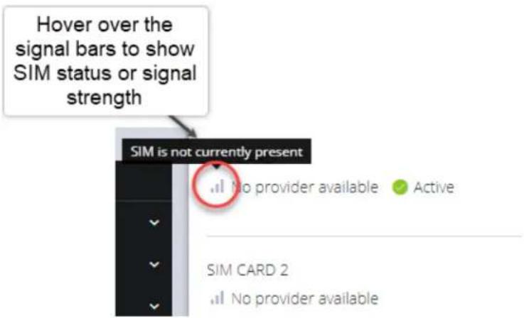
text_image
Hover over the signal bars to show SIM status or signal strength SIM is not currently present No provider available ● Active SIM CARD 2 No provider availableThe signal bar color (not the number of bars) indicates signal strength:
- Green if signal is above the higher threshold.
- Orange if signal is between lower and higher threshold.
• Red if signal is below the lower threshold, - Grey for 0 or not active,
CONFIGURE MENU 65
- Click the Refresh button to display the current signal strength of the active SIM.
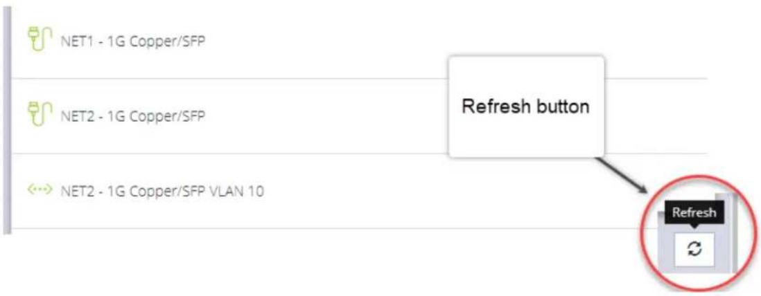
flowchart
graph TD
    A["NET1 - 1G Copper/SFP"] --> B["Refresh button"]
    C["NET2 - 1G Copper/SFP"] --> B
    D["NET2 - 1G Copper/SFP VLAN 10"] --> B
    B --> E["Refresh"]
Note: When the Refresh button is clicked the signal strength is only updated for the active SIM. If you would like to know what the other SIM Signal Strength is, you need to activate it, let the modem come back online, which may take 3 minutes or more.
Installing A New SIM Card
Before installing a new SIM card, the OM device must first be powered down. This can be done by switching off the power supply and waiting until the device has shut-down. Install the new SIM card into its slot, then restart the device
Note: The device will not recognize the new SIM card unless a shut-down and restart is performed. The new SIM card will be read during start-up.
Select The Active SIM (Manual Failover Mode)
Switching the active SIM must be done manually. To switch the Active SIM:
- Navigate to CONFIGURE > NETWORK CONNECTIONS > Network Interfaces > Cellular Interface (LTE.
- Click the Settings cog, this will display the MANAGE CELLULAR INTERFACE (LTE) page and the current status of both SIM slots, including the current carrier name.

Cellular Interface (LTE)
Enabled
Disabled
No SIM

- On the right, select the Make Active button of the new, active SIM and apply the change by selecting Confirm.
- A pop-up alert states that this operation will take a few minutes to complete. Click Yes to confirm the change.
SWITCH ACTIVE SIM
×
Switching the active SIM will take a few minutes to complete while the modem is being provisioned. Do you wish to proceed with this operation?
No
Yes
Note: During the change-over the current IP address is hidden and then returned when the modem re-connects.
- If you require, you can monitor the interface during the changeover via the CLI with the command:.
watch ip address show dev wwan0
CONFIGURE MENU 67

opengear
You can also set the SIM settings by expanding the menu for each SIM to set the APN.
If no SIM is inserted you can still select a SIM slot. If you insert a SIM it will not force it to become the active SIM.
Select The Primary SIM (Automatic Failover Mode)
Switching the primary SIM must be done manually. To switch the Primary SIM:
- Navigate to CONFIGURE > NETWORK CONNECTIONS > Network Interfaces > Cellular Interface (LTE.
- Click the Editicon, this will display the MANAGE CELLULAR INTERFACE (LTE) page and the current status of both SIM slots.
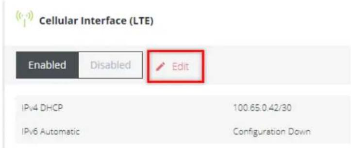
text_image
Cellular Interface (LTE) Enabled Disabled Edit IPv4 DHCP 100.65.0.42/30 IPv6 Automatic Configuration Down-
Ensure the cellular interface is enabled by clicking the Enabled button.
-
Under Cellular SIM Failover click the Automatic button, this will display the Primary selection buttons.
CELLULAR SIM FAILOVER ?
▲ Cellular SIM Failover may take a few minutes due to the need to switch firmware.
Primary - SIM CARD 1
Verizon Wireless
ICCID: 89148000005844013102
SIM Settings
Secondary - SIM CARD 2
AT&T Wireless Inc.
ICCID: 89010303300021797361
SIM Settings
Make Primary
- Click the Primary button of the SIM selected to be the primary SIM.
- Click the Confirm button at the bottom of the page. A green banner will appear to confirm that the new settings have been saved.
Dual SIM Automatic Failover
CONFIGURE > NETWORK CONNECTIONS> Network Interfaces > Cellular Interface (LTE)
Devices that carry two SIM cards can be configured so that either SIM card slot may be activated. In Automatic failover mode, either of the two SIM cards may be designated as the Primary SIM. (see "Dual SIM" on page 64).
Dual SIM Automatic Failover works seamlessly with the existing failover solution to provide another layer of redundancy. This feature allows the software to detect a failure in OOB communications via the Primary SIM and will automatically failover to the Secondary SIM without the need for manual operator intervention.
Options within the configuration also allow you to configure the failback settings from Secondary SIM, back to the previous Primary SIM when OOB communications have been restored. See "Cellular Interface Policy Settings" on page 74.
Note: The terminology changes when SIM Failover policy is switched from Manual to Automatic. In Manual mode the active SIM is designated ACTIVE, whereas in Automatic failover mode the active SIM is designated PRIMARY.
See the image on the following page for a depiction of Primary and Secondary SIM card slots.

opengear
Either of the SIM card slots can be designated as the Primary SIM. In the following image, SIM card 1 has been designated as the Primary SIM and is currently the active SIM, while SIM card 2 is designated as the Secondary SIM which, (in the scenario below), is only activated in the event of an automatic failover such as occurs during an OOB communications failure on the Primary SIM.
CELLULAR SIM FAILOVER ?
Automatic
Manual
▲ Cellular SIM Fallover may take a few minutes due to the need to switch firmware.
Primary - SIM CARD 1
Verizon Wireless
ICCID: 89148000005844013102
SIM Settings
Secondary - SIM CARD 2
AT&T Wireless Inc.
ICCID: 89010303300021797361
SIM Settings
Make Primary
CONFIGURE MENU 71
Failover Modes
Features of Automatic Failover include:
- Select either Manual or Automatic SIM failover.
-
Specify SIM failback policy (applicable when the Ethernet connection and primary SIM are both down):
-
Upon disconnect - See the table "Cellular Interface Policy Settings" on page 74 for an explanation of the policy.
• After a Delay (specified in minutes) - The device switches back to primary after a pre-defined time has elapsed.
. Never - The device never switches back to the Primary.
- SIM failover settings allow you to configure the parameters that affect cellular data usage, for example, quicker failover (consumes more data) vs less frequent tests (consumes less data). The configuration preferences include
- Ping test for failover from Primary to Secondary and failback from Secondary to Primary.
- Failover settings are per SIM slot and consist of a failover and failback ping test.
• Automatic Failover functions in both dormant and non-dormant mode.
Activate or Configure Automatic Failover
CONFIGURE > NETWORK CONNECTIONS> Network Interfaces > Cellular Interface (LTE) > Manage Cellular Interface (LTE)
- Navigate to the Cellular Interface page at: CONFIGURE > NETWORK CONNECTIONS> Network Interfaces > Cellular Interface (LTE).
- Click the Edit link next to the Cellular Interface Enabled/Disabled switch.

Cellular Interface (LTE)
Enabled
Disabled

Edit
IPv4 DHCP
100.65.0.42/30
IPv6 Automatic
Configuration Down
- In the Manage Cellular Interface page, select the Automatic failover option.
- Ensure the correct SIM card is selected as the Primary SIM (see 'Set Primary SIM' in "Dual SIM" on page 64).
- Complete the Cellular Interface options in accordance with the table below.
- Click Confirm to activate the failover policy settings, a green banner will confirm the settings are enabled.
Cellular Interface Policy Settings
| MANAGE CELLULAR INTERFACE (LTE) Properties | |
| Field Definition | |
| CELLULAR SIM FAILOVER - Manual/Automatic. | Automatically switch between the Primary SIM Card and the secondary SIM Card on disconnection. |
| Primary SIM Failover | |
| Failover Probe Address. Network address to probe in order to determine if connection is active.Note: The probe address accepts IPv4, IPv6 addresses and hostnames. | |
| Test interval (seconds). The number of seconds between connectivity probe tests. | |
| Pings per test. The maximum number of times a single ping packet is sent per probe before considering the probe failed. | |
| Consecutive test failures before failover. | The number of times a probe must fail before the connection is considered failed. |
| Failback Policy | |
| Never / Delayed / On Disconnect. | Select the policy to be used to determine Failback recovery from the Secondary SIM Card back to the Primary SIM Card. |
| Never No Failback recovery | is attempted. |
| Delayed Attempted failback | after n minutes. The number of minutes after failover to the secondary SIM Card that the connection should failback to the Primary SIM Card. |
CONFIGURE MENU 74
| On Disconnect Secondary SIM Failback |
| Failback Probe Addressie. The Network address to probe in order to determine if the connection is active. |
| Test IntervalThe number of seconds between connectivity probe tests (this not the same thing as Attempt Failback). |
| Pings per TestThe maximum number of times a single ping packet is sent per probe before considering the probe failed. |
| Consecutive Test Failures (before failover)The number of times a probe must fail before t connection is considered failed. |
Network Aggregates - Bonds and Bridges
CONFIGURE > NETWORK CONNECTIONS > Network Interfaces > Select the target interface
The Network Aggregates feature allows you to create or edit bridges that contain any type of interface or other config options which are included in a bridge or bond after it is created, without having to delete the bridge or bond and start over. Such changes can be made remotely without organizing a site visit.. The supported configuration options for bonds and bridges are discussed in the Bridge and Bond Definitions tables later in this topic.
This also includes other settings on bonds, such as the mode or poll interval.
Note: Editing the primary interface will not update its connections.
Operations Manager models with an integrated switch (OM1204-4E, OM1208-8E and OM2224-24E) have a bridge configured by default that includes all of the switch ports, which can be edited or deleted as required.
Definitions of the bridge details as in the Bridge Form Definitions table below.
Create A New Bridge
Note: Whether creating a new bridge or editing an existing bridge the page is very similar.
To create a new bridge:
-
Navigate to the Configure > Network Connections > Network Interfaces page on the Web UI.
-
Click on the New Bridge button that is located at the top-right of the window.
CONFIGURE MENU 76
- Select which interface will serve as the primary interface for the new bridge.
Note: When the primary interface is selected, its MAC address is displayed in the MAC address field. This MAC address is inherited by the new bridge interface.
-
Complete the new bridge details form as in the Bridge Form Definitions definitions table below.
-
Click the Create button to finalize the creation of the new bridge.
Edit an Existing Bridge
To edit an existing bridge:
-
Navigate to the Configure > Network Connections > Network Interfaces page on the Web UI.
-
Click on the bridge that you would like to edit, the bridge details are expanded.
-
Click on the bridge Edit button that is located next to the Enable / Disable toggle buttons.
-
Select which interface will serve as the primary interface for the new bridge.
-
Change the bridge details as required in accordance with the Bridge Form Definitions table below.
-
Click the Update button to finalize the edit process. Updating the bridge will temporarily interrupt network activity on this interface.
Edit Bridge Form Definitions
| New Bridge Field | Definition |
| Description The editable | Description field allows you to add a description of the interface. If the description field is not completed the field will default to a computed value to describe the interface. |
| Enable Spanning Tree Protocol? | Spanning Tree Protocol allows Operation Manager devices to:Discover and eliminate any unexpected networks loops so that there is no broadcast radiation and the network stays healthy and reliableBe able to function with redundant links (intentional network loops) to increase the networks reliability and fault tolerance |
| Network Interface Selection | Click the check box of each network interface you want to include in the bridge. |
| Primary Interface | Select the interface that is to be used for selecting the MAC address of the aggregate. The new bond inherits the MAC address of the primary interface. On creation, any Network Connections which exist on the Primary Interface will be attached to the Bond/Bridge after it is initially created. When a Bond/Bridge is deleted, any Network Connections which exist on the aggregate interface are handed over to the Primary Interface. |
| Inherited Connections | When the Primary Interface is selected, the connections inherited by the new bridge are listed here. |
| Edit | Click to edit the details of an existing interface. |
| CONFIGURE MENU 78 |
Create A New Bond
Note: Whether creating a new bond or editing an existing bond the page is very similar.
To create a new bond:
- Navigate to the Configure > Network Connections > Network Interfaces page on the Web UI.
- Click on the New Bond button that is located at the top-right of the window.
- Select which interface will serve as the primary interface for the new bond.
Note: When the primary interface is selected, its MAC address is displayed in the MAC address field. This MAC address is inherited by the new bond interface.
- Complete the new bond details form as in the Bond Form Definitions definitions table below.
- Click the Create button to finalize the creation of the new bond. Network connections from non-primary interfaces will be deleted when the new bond is created.
Edit an Existing Bond
To edit an existing bond:
- Navigate to the Configure > Network Connections > Network Interfaces page on the Web UI.
- Click on the bond that you would like to edit, the bond details are expanded.
- Click on the bond Edit button that is located next to the Enable / Disable toggle buttons.
CONFIGURE MENU 79
-
Change the bond details as required in accordance with the Edit Bond Form Definitions table below.
-
Click the Update button to finalize the edit process. Updating the bond will temporarily interrupt network activity on this interface.
Edit Bond Form Definitions
| New Bond Field Definition | |
| Description The editable | Description field allows you to add a description of the interface. If the description field is not completed the field will default to a computed value to describe the interface. |
| Mode | The mode determines the way in which traffic sent out via the bonded interface is dispersed over the real interfaces. Available modes are: |
| Round Robin Balancing - Packets are sequentially transmitted/received through each interfaces one by one. | |
| Active Backup If the active secondary interface is changed during a failover, the bond interface's MAC address is then changed to match the new active secondary's MAC address. | |
| XOR Balancing Balances traffic by splitting up outgoing packets between the Ethernet interfaces, using the same one for each specific destination when possible. | |
| Broadcast - All network transmissions are sent on all secondary interfaces. This mode provides fault tolerance. | |
| 802.3ad (Dynamic Link Aggregation) Aggregated NICs act as one NIC, but also provides failover in the case that a NIC fails. Dynamic Link Aggregation requires a switch that supports IEEE 802.3ad. | |
CONFIGURE MENU 80
| Transmit Load BalancingOutgoing traffic is distributed depending on the current load on each secondary interface. Incoming traffic is received by the current secondary interface. If the receiving secondary fails, another secondary takes over the MAC address of the failed secondary. | |
| Adaptive Load Balancingincludes transmit load balancing (tlb) and receive load balancing (rlb) for IPv4 traffic and does not require any special switch support. | |
| Poll Interval The poll interval specifies the MII link monitoring frequency in milliseconds. This determines how often the link state of each secondary is inspected for link failures. A value of zero disables MII link monitoring. | |
| Network Interface Selection | Click the check box of each network interface you want to include in the bridge. |
| Primary Interface | Select the interface that is to be used for selecting the MAC address of the aggregate. The new bond inherits the MAC address of the primary interface. On creation, any Network Connections which exist on the Primary Interface will be attached to the Bond/Bridge after it is initially created. When a Bond/Bridge is deleted, any Network Connections which exist on the aggregate interface are handed over to the Primary Interface. |
| Active Connections | When the Primary Interface is created, the connections inherited by the new bond are listed here. When edited, Active Connections on the aggregate will not be updated if the primary interface is changed. |
| Edit | Click to edit the details of an existing interface. Updating a bridge will temporarily interrupt network activity on the interface when you click the update button. |
| CONFIGURE MENU 81 |
Spanning Tree Protocol
CONFIGURE > NETWORK CONNECTIONS > Network Interfaces > Select the target interface
Spanning Tree Protocol (STP) allows Operation Manager devices to discover and eliminate loops in network bridge links, preventing broadcast radiation and allowing redundancy.
When STP is implemented on switches to monitor the network topology, every link between switches, and in particular redundant links, are cataloged. The spanning-tree algorithm blocks forwarding on redundant links by setting up one preferred link between switches in the LAN. This preferred link is used for all Ethernet frames unless it fails, in which case a non-preferred redundant link is enabled.
Note: STP Limitations
If multiple bridges are created on the same switch they should not be used on the same network segment as they have the same MAC addresses, therefore STP will likely not work correctly as they will have the same bridge id. Rapid Spanning Tree Protocol (RSTP), Multiple Spanning Tree Protocol (MSTP) and other proprietary protocols are not supported.
The bridge settings relating to STP cannot be changed from the default values shown below:
group_address
forward_delay (default is 15)
hello_time (default is 2)
max_age (default is 20)
priority (default is 32768 (0x8000))
Enable STP in a Bridge
To enable STP you can use the UI or CLI. The procedures are:
Bridge With STP Enabled - UI
CONFIGURE > NETWORK CONNECTIONS > Network Interfaces > Select the target interface > New Bridge page
- In the Network Interfaces page, click the Create New Bridge button.
- Click to select the Enable Spanning Tree Protocol option.
NEW BRIDGE
Description
New Bridge
√ Enable Spanning Tree Protocol ☑
Bridge With STP Enabled - OGCLI
admin@om2248:~# ogcli get physif system_net_physifs-5
bridge_setting.id="system_net_physifs-5"
bridge_setting.stp_enabled=true
description="Bridge"
device="br0"
enabled=true
id="system_net_physifs-5"
media="bridge"
name="init_br0"
slaves[0]="net2.3"
CONFIGURE MENU 83
Bridge With STP Disabled - OGCLI
admin@om2248:~# ogcli update physif system_net_physifs-5
bridge_setting.stp_enabled=false
bridge_setting.id="system_net_physifs-5"
bridge_setting.stp_enabled=false
description="Bridge"
device="br0"
enabled=true
id="system_net_physifs-5"
media="bridge"
name="init_br0"
slaves[0]="net2.3"
IPsec Tunnels
CONFIGURE > NETWORK CONNECTIONS > IPsec Tunnels
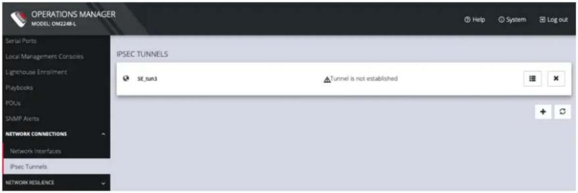
On the IPsec Tunnels page, you can create, edit, and delete IPsec tunnels.
text_image
OPERATIONS MANAGER MODEL: OM2248-L Serial Ports Local Management Consoles Lighthouse Enrollment Playbooks POUs SNMP Alerts NETWORK CONNECTIONS Network Interfaces IPsec Tunnels NETWORK RESILIENCE IPSEC TUNNELS SE_tun3 Tunnel is not establishedTo create an IPsec tunnel:
- Click CONFIGURE > NETWORK CONNECTIONS > IPsec Tunnels.
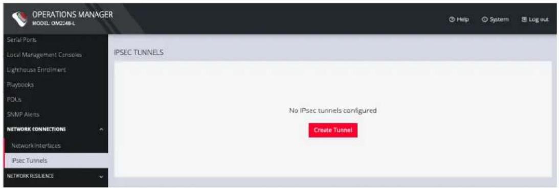
text_image
OPERATIONS MANAGER MODEL: OM2248 L Serial Ports Local Management Conspies Lighthouse Enrollment Playbooks POUs SNMP Alerts NETWORK CONNECTIONS Network Interfaces IPsec Tunnels NETWORK RESILIENCE IPSEC TUNNELS No IPsec tunnels configured Create Tunnel- Click CREATE TUNNEL. This opens the EDIT IPSEC TUNNEL page.
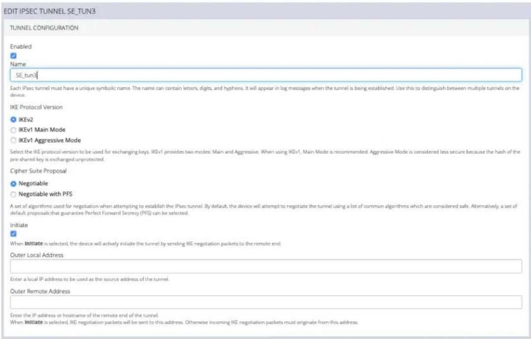
text_image
EDIT IPSEC TUNNEL SE_TUN3 TUNNEL CONFIGURATION Enabled # Name SE_TUN3 Each iPSec tunnel must have a unique symbolic name. The name can contain letters, digits, and hyphens. It will appear in log messages when the tunnel is being established. Use this to distinguish between multiple tunnels on the device. IKE Protocol Version ● IKEv2 ○ IKEv1 Main Mode ○ IKEv1 Aggressive Mode Select the IKE protocol version to be used for exchanging keys. IKEv1 provides two modes: Main and Aggressive. When using IKEv1, Main Mode is recommended. Aggressive Mode is considered less secure because the hash of the pre-shared key is exchanged unprotected. Cipher Suite Proposal ● Negotiable ○ Negotiable with PFS A set of algorithms used for negotiation when attempting to establish the iPSec tunnel. By default, the device will attempt to negotiate the tunnel using a list of common algorithms which are considered safe. Alternatively, a set of default proposals that guarantee Perfect Forward Secrecy (PFS) can be selected. Initiate # When Initiate is selected, the device will actively initiate the tunnel by sending IKE negotiation packets to the remote end. Outer Local Address Enter a local IP address to be used as the source address of the tunnel. Outer Remote Address Enter the IP address or hostname of the remote end of the tunnel. When Initiate is selected, IKE negotiation packets will be sent to this address. Otherwise incoming IKE negotiation packets must originate from this address.-
In the top section of the page, TUNNEL CONFIGURATION, click the Enabled check box and give your new tunnel a name.
-
Select an IKE Protocol Version to use for exchanging keys. IKEv1 provides two modes: Main and Aggressive. When using IKEv1, Main Mode is recommended. Aggressive Mode is considered less secure because the hash of the pre-shared key is exchanged unprotected.
-
Select a Cipher Suite Proposal. This is a set of algorithms used for negotiation when attempting to establish the IPsec tunnel. By default, the device will attempt to negotiate the tunnel using a list of common algorithms which are considered safe. Alternatively, a set of default proposals that guarantee Perfect Forward Secrecy (PFS) can be selected.
-
Click the Initiate checkbox to actively initiate the tunnel by sending IKE negotiation packets to the remote end.

opengear
- Enter an Outer Local Address, a local IP address to use as the source address of the tunnel
- Enter an Outer Remote Address, the IP address or hostname of the remote end of the tunnel.
- Scroll down to the Traffic Selectors section of the page.
TRAFFIC SELECTORS
The traffic selectors specify which IP traffic will be sent through this tunnel. Each traffic selector is a comma-separated list of subnets in CIDR notation or IP addresses. For example: 192.168.0.1 matches a single IP address, or 10.1.0.0/16, 10.2.0.0/16 matches two subnets.
Typically the remote traffic selector configured on this device must match the local traffic selector configured on the other end of the tunnel, and vice versa.
Local Subnet
Specify local traffic to be tunneled.
When no subnets are specified, only traffic originating from this device will be tunneled.
Remote Subnet
Specify addresses or subnets which are behind the remote end of this tunnel.
When no subnets are specified, only traffic originating from the outer remote address will be accepted.
- Enter a Local Subnet and Remote Subnet.
- Scroll down to the third section, AUTHENTICATION.
AUTHENTICATION
PSK Shared Secret
For the pre-shared key authentication mode, both ends of the tunnel must use the same key.
Local ID
Specify the identity of this end of the tunnel, to be presented during IKE negotiation. Fill this in if the remote end requires it for authentication.
To construct ID_USER_FQDN type identities, use user@example.com
To construct ID_FQDN type identities, use @host.example.com
If this is left blank, the outer local IP address of the tunnel is used as the identity.
Remote ID
Specify the expected identity of the remote end of the tunnel. The tunnel will only be established if the remote end's identity matches this value. This field accepts the same syntax as the Local ID.
If this is left blank, any remote identity will be accepted.
Cancel
Save
- Enter a PSK Shared Secret.
- Enter a Local ID and Remote ID.
- Click Save. The new tunnel is now listed on the CONFIGURE > NETWORK CONNECTIONS > IPsec Tunnels page.
Network Resilience
CONFIGURE > NETWORK RESILIENCE >
Under the NETWORK RESILIENCE menu, you can manage Out-of-Band (OOB) and IP Passthrough settings.
OOB Failover
CONFIGURE > NETWORK RESILIENCE > OOB Failover
To manage Out-of-Band failover, click CONFIGURE
NETWORK RESILIENCE > OOB Failover:
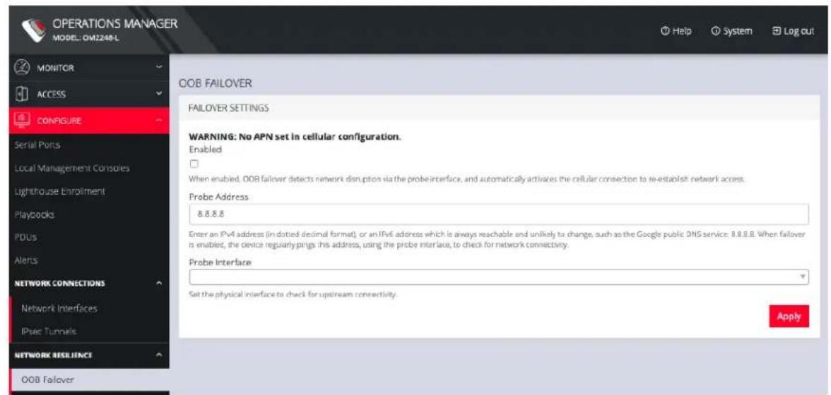
text_image
OPERATIONS MANAGER MODEL: OM2248-L MONITOR ACCESS CONFIGURE Serial Ports Local Management Consoles Lighthouse Enrollment PlayDocks PDUs Alerts NETWORK CONNECTIONS Network Interfaces IPv6 Tunnels NETWORK RESILIENCE OOB Failover OOB FAILOVER FAILOVER SETTINGS WARNING: No APN set in cellular configuration. Enabled When enabled, OOB failover detects network disruption via the probe interface, and automatically activates the cellular connection to re-establish network access. Probe Address 8.8.8.8 Enter an IPv4 address (in dotted decimal format) or an IPv6 address which is always reachable and unlikely to change, such as the Google public DNS service: 8.8.8.8. When failover is enabled, the device regularly pings this address, using the probe interface, to check for network connectivity. Probe Interface Set the physical interface to check for upstream connectivity. ApplyIP Passthrough
CONFIGURE > NETWORK RESILIENCE > IP Passthrough
To manage IP Passthrough settings clickCONFIGURE
NETWORK RESILIENCE > OOB Failover:
IP PASSTHROUGH
SETTINGS
□ Enable ⑦
Interface
○ NET1 - 1G Copper/SFP
○ NET2 - 1G Copper/SFP
The device will offer a DHCP lease for the cellular IP address on this interface.
Downstream MAC Address
00:00:00:00:00:00
The DHCP lease will only be offered to this MAC address. DHCP requests from other MAC addresses will be ignored. Enter the MAC address of the downstream device.
SERVICE INTERCEPTS
When IP Passthrough is enabled above, access to this device directly via the cellular interface will no longer work. You can configure specific ports below which will be redirected to this device instead of the downstream device.
HTTPS Intercept Port
A
Enter a port to be redirected to this device's HTTPS service. You can use this port to access the Operations Manager web interface. If you leave this field blank, the HTTPS service intercept will be disabled.
SSH Intercept Port
A
Enter a port to be redirected to this device's SSH service. You can use this port to access the Operations Manager command line interface. If you leave this field blank, the SSH service intercept will be disabled.
©
Apply
CONFIGURE MENU 91
User Management
CONFIGURE > USER MANAGEMENT
Under the User Management menu, you can create, edit, and delete groups and users, as well as assign users to groups. You can also set up remote user authentication.
Groups
CONFIGURE > USER MANAGEMENT > Groups
To create a new group:
- Select CONFIGURE > USER MANAGEMENT > Groups.
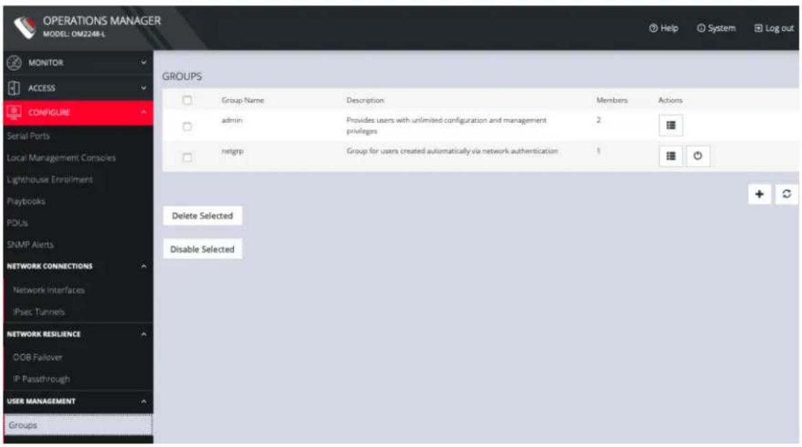
text_image
OPERATIONS MANAGER MODEL: OM2248-L MONITOR ACCESS CONFIGURE Serial Ports Local Management Consoles Lighthouse Enrollment Playbooks POUs SNMP Alerts NETWORK CONNECTIONS Network Interfaces iSpec Tunnels NETWORK RESILIENCE OOB Fialover IP Pansthrough USER MANAGEMENT Groups GROUPS Group Name Description Members Actions admin Provides users with unlimited configuration and management privileges 2 netgrp Group for users created automatically via network authentication 1 Delete Selected Disable Selected- Click the Plus button. The NEW GROUP page opens.
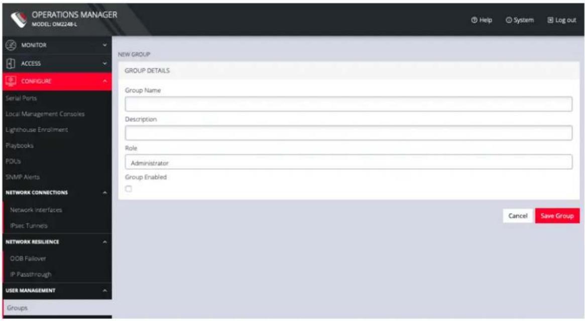
text_image
OPERATIONS MANAGER MODEL: 0M2248-L MONITOR ACCESS CONFIGURE Serial Ports Local Management Consoles Lighthouse Enrollment Playbooks POUs SNMP Alerts NETWORK CONNECTIONS Network Interfaces iPsec Tunnels NETWORK RESILIENCE O/OB Fallover IP Passsthrough USER MANAGEMENT Groups NEW GROUP GROUP DETAILS Group Name Description Role Administrator Group Enabled Cancel Save Group- Enter a Group Name, Description, and select a Role for the group.
- Choosing the Console User role allows you to select specific ports this group will be able to access.
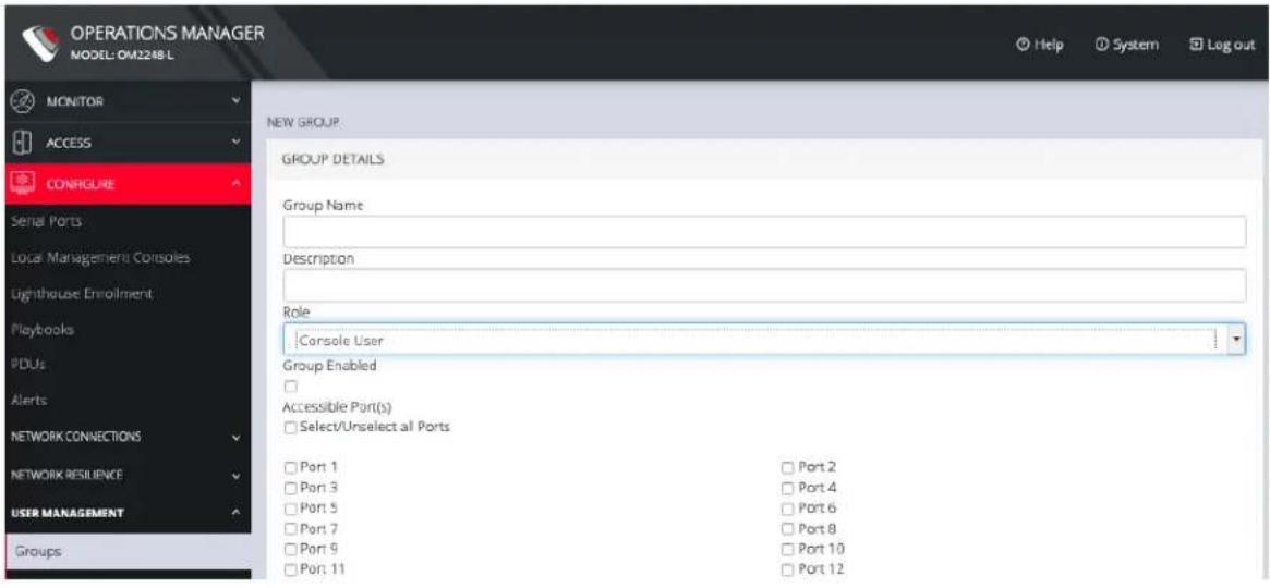
text_image
OPERATIONS MANAGER MODEL: OM2248 L MONITOR ACCESS CONREGURE Serial Ports Local Management Consoles Lighthouse Enrollment Playbooks PDUs Alerts NETWORK CONNECTIONS NETWORK RESILIENCE USER MANAGEMENT Groups NEW GROUP: GROUP DETAILS Group Name Description Role Console User Group Enabled □ Accessible Port(s) □ Select/Unselect all Ports □ Port 1 □ Port 2 □ Port 3 □ Port 4 □ Port 5 □ Port 6 □ Port 7 □ Port 8 □ Port 9 □ Port 10 □ Port 11 □ Port 12CONFIGURE MENU 94

opengear
-
Click the Group Enabled checkbox to enable the group. After creation, groups can also be enabled or disabled from the CONFIGURE > USER MANAGEMENT > Groups page.
-
Click Save Group.
Note: Group Name is case sensitive. It can contain numbers and some alphanumeric characters. When using remote authentication, characters from a user's remote groups that are not allowed are converted to underscores during authentication. Local groups can be created that take that into account, allowing the authentication to continue.
If the Role selected is Administrator, members of the group have full access to and control of all managed devices, full system configuration privileges, and full access to the command line shell.
To modify an existing group:
-
Select CONFIGURE > USER MANAGEMENT > Groups.
-
Click Edit in the Actions section of the group to be modified and make desired changes.
-
Click Save Group.
The CONFIGURE > User Management > Groups page also allows administrators to delete a group. Users who were members of the deleted group lose any access and administrative rights inherited from the group.
Note: The netgrp group is inherited as the primary group for all remote AAA users who are not defined locally. By default, netgrp has the Administrator role and is disabled. It must be enabled to take effect for remote AAA users.
CONFIGURE MENU 95
Local Users
CONFIGURE > USER MANAGEMENT > Local Users
To create a new user:
- Navigate to the CONFIGURE > USER MANAGEMENT > Local Users tab.
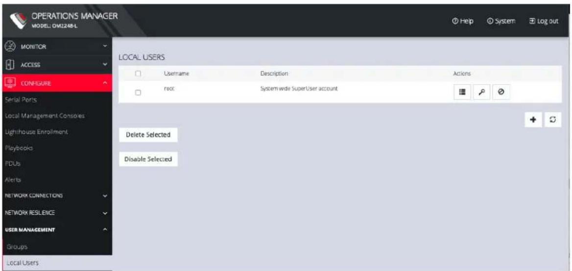
text_image
OPERATIONS MANAGER MODEL: DM2248-L MONITOR ACCESS CONFIGURE Serial Ports Local Management Consoles Lighthouse Enrollment Playbooks PCUs Alerts NETWORK CONNECTIONS NETWORK RESILENCE USER MANAGEMENT Groups Local Users LOCAL USERS Username Description Actions root System wide SuperUser account Delete Selected Disable Selected- Click the + button. The New User dialog appears.
CONFIGURE MENU 96
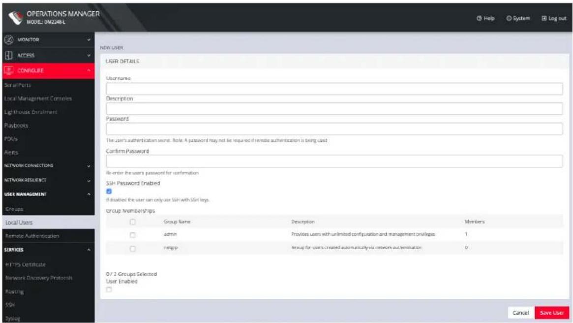
text_image
OPERATIONS MANAGER MODEL: ON2248-L MONITOR ACCESS CONFIGURE Serial Ports Local Management Consoles Lighthouse Enrolment Playbooks POUs Alerts NETWORK CONNECTIONS NETWORK RESUENCE USER MANAGEMENT Groups Local Users Remote Authentication SERVICES HTTPS Certificate Network Discovery Protocols Routing SSH Typing NEW USER USER DETAILS Username Description Password The user's authentication secret. Note: A password may not be required if remote authentication is being used Confirm Password Re-enter the user's password for confirmation SSH Password Enabled If disabled the user can only use SSH with SSH keys. Group Memberships Group Name Description Members admin Provides users with unlimited configuration and management obligations 1 Integp Group for users created automatically via network authentication 0 0 / 2 Groups Selected User Enabled Cancel Save User- Enter a Username, Description, and Password.
- Re-enter the Password in the Confirm Password field.
- Select the Enabled checkbox.
- Click Apply.
To create a new user without password which causes them to fall back to remote authentication:
- Select CONFIGURE > User Management > Remote Authentication
- Select a Scheme.
- Enter Settings and click Apply.
- Select CONFIGURE > USER MANAGEMENT > Local Users
- Click the + button. The New User dialog loads.
- Enter a Username, Description.
- Select the Remote PasswordOnly checkbox.
CONFIGURE MENU 97

opengear
- Select the Enabled checkbox.
- Click Apply.
To modify an existing user:
-
Select CONFIGURE > USER MANAGEMENT > Local Users
-
Click the Edit User button in the Actions section next to the user to be modified and make desired changes.
-
Click Save User.
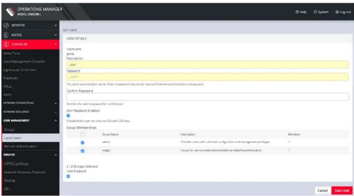
text_image
OPERATIONS MANAGER MODEL:OM2248-L MONITOR ACCESS CONCRETE Serial Parts Local Management Consoles Lighthouse Enpliment Playbooks FOUs Alerts NETWORK CONNECTIONS NETWORK RESLENCE USER MANAGEMENT Groups Local Users Remote Authentication SERVICES HTTPS Certificate Network Discovery Provoirs Routing 25-1 EDIT USER USER DETAILS Username ymb Description host Password Other The User's authentication secret. Note: A password may not be required if remote authentication is being used. Confirm Password Re-enter the user's password for confirmation SSH Password Enabled If disabled the user can only use SSH with SSH keys. Group Memberships Group Name Description Members admin Provides users with unlimited configuration and management privileges 3 mgrp Group for users created automatically via network authentication 1 2 / 2 Groups Selected User Enabled Cancel Save UserThe Edit Users dialog allows the user's Description to be changed, Group Memberships modified, and the user's Password to be reset. The username cannot be changed. To disable a user, uncheck the Enabled checkbox.
Disabled users cannot log in to the OPERATIONS MANAGER using either the Web-based interface or via shell-based logins.
To manage SSH authorized keys for a user:
CONFIGURE MENU 98

opengear
- Select CONFIGURE > USER MANAGEMENT > Local Users
- Click the Manage SSH Authorized Keys button in the Actions section next to the user.
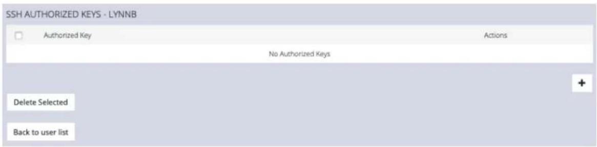
text_image
SSH AUTHORIZED KEYS - LYNNB Authorized Key Actions No Authorized Keys Delete Selected Back to user list- Click the Plus button to add a new key. This opens the NEW AUTHORIZED KEY page for this user.
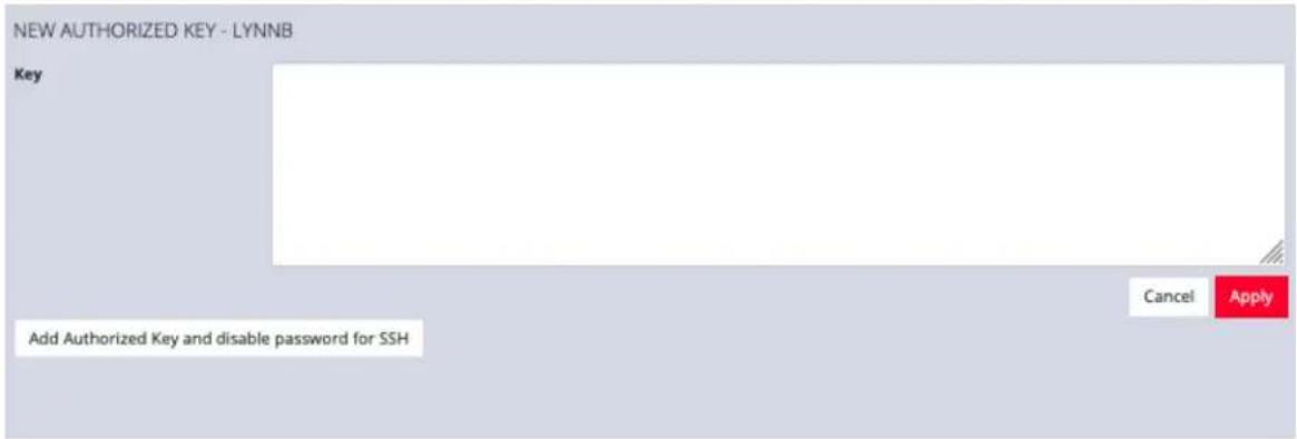
text_image
NEW AUTHORIZED KEY - LYNNB Key Add Authorized Key and disable password for SSH Cancel Apply- Enter the key and click Apply. You can also click on Add Authorized Key and disable password for SSH for this user from this page.
- To delete a key, click CONFIGURE > USER MANAGEMENT > Local Users and click the Authorized Key button for the user.
CONFIGURE MENU 99
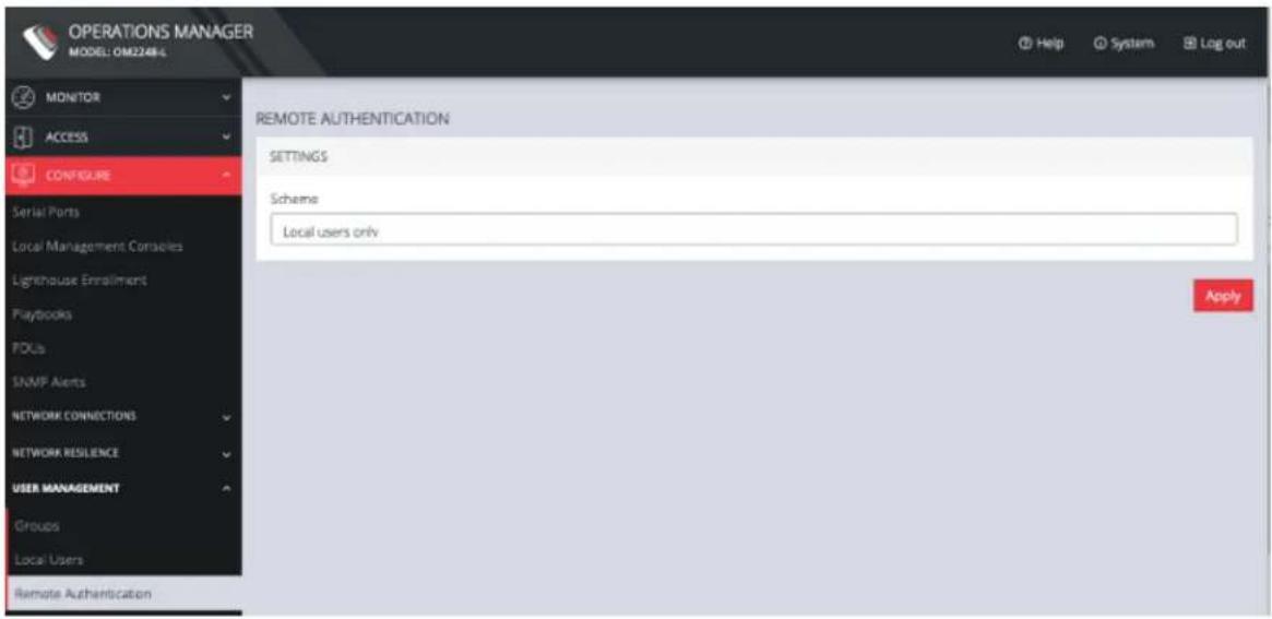
text_image
OPERATIONS MANAGER MODEL: OM2248-4 MONITOR ACCESS CONFIGURE Serial Ports Local Management Consoles Lighthouse Enrollment Playbooks FDUs SNMP Alerts NETWORK CONNECTIONS NETWORK RESILIENCE USER MANAGEMENT Groups Local Users Remote Authentication REMOTE AUTHENTICATION SETTINGS Scheme Local users only Apply- Click the Delete button next to the key you wish to remove.
To delete a user:
- Select CONFIGURE > USER MANAGEMENT > Local Users
- Click the Delete User button in the Actions section next to the user to be deleted.
- Click Yes in the Confirmation dialog.
Remote Authentication
CONFIGURE > USER MANAGEMENT > Remote Authentication
The OPERATIONS MANAGER supports three AAA systems:
• LDAP (Active Directory and OpenLDAP)
• RADIUS
- TACACS+
To begin, select CONFIGURE > USER MANAGEMENT > Remote Authentication.
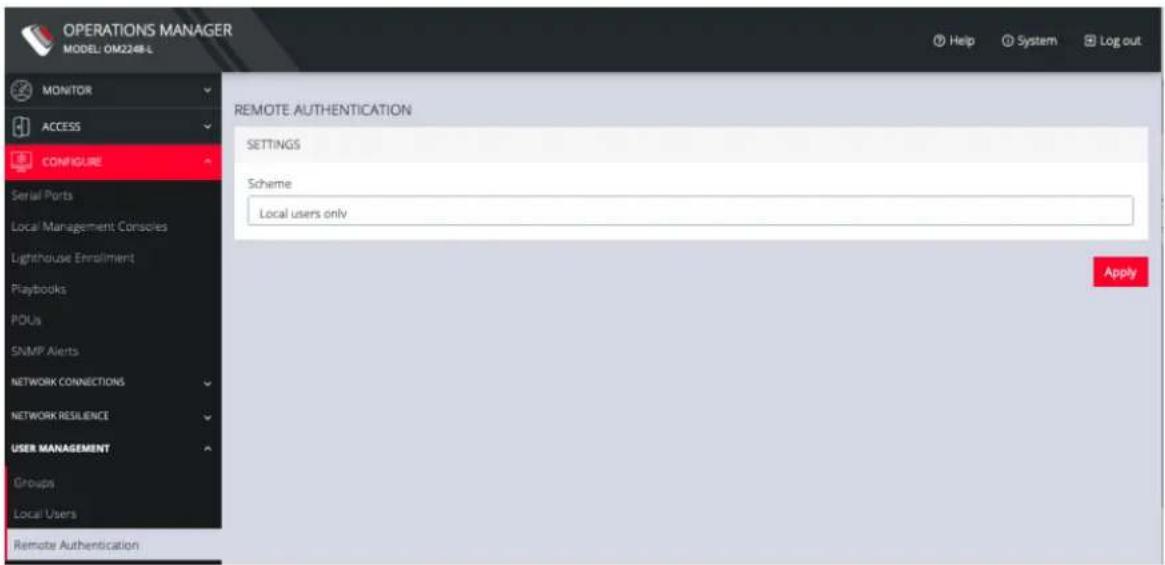
text_image
OPERATIONS MANAGER MODEL: OM2248-L MONITOR ACCESS CONFIGURE Serial Ports Local Management Consoles Lighthouse Enrollment Playbooks POUs SNMP Alerts NETWORK CONNECTIONS NETWORK RESILIENCE USER MANAGEMENT Groups Local Users Remote Authentication REMOTE AUTHENTICATION SETTINGS Scheme Local users only ApplyTo configure LDAP authentication (for example):
- Under CONFIGURE > User Management > Remote Authentication, select LDAP from the Mode drop-down menu.
CONFIGURE MENU 101
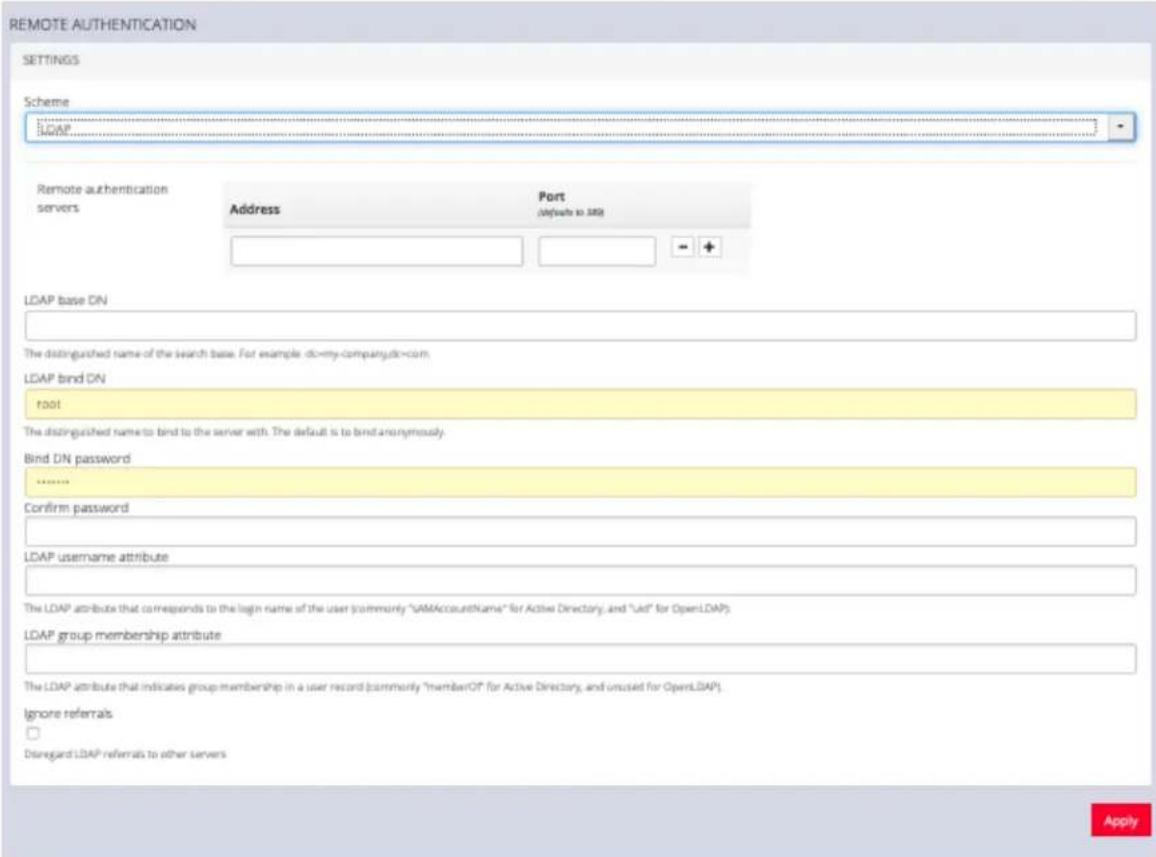
text_image
REMOTE AUTHENTICATION SETTINGS Scheme LDAP Remote authentication servers Address Port (Default to SIM) LDAP base ON The distinguished name of the search base. For example: dc=my-company.dc=com. LDAP bind ON root The distinguished name to bind to the server with. The default is to bind anonymously. Bind DN password ****** Confirm password LDAP username attribute The LDAP attribute that corresponds to the login name of the user (commonly "SAMAccountName" for Active Directory, and "Lid" for OpenLDAP). LDAP group membership attribute The LDAP attribute that indicates group membership in a user record (commonly "memberOf" for Active Directory, and unused for OpenLDAP). Ignore referrals Disregard LDAP referrals to other servers Apply- Add the Address and optionally the Port of the LDAP server to query.
- Add the Base DN that corresponds to the LDAP system being queried.
For example, if a user's distinguished name is cn=John Doe,d-c=Users,dc=ACME,dc=com, the Base DN is dc=ACME,dc=com
- Add the Bind DN. This is the distinguished name of a user with privileges on the LDAP system to perform the lookups required for retrieving the username of the users, and a list of the groups they are members of.
- Add the password for the binding user.
CONFIGURE MENU 102

opengear
- Add the Username Attribute. This depends on the underlying LDAP system. Use sAMAccountName for Active Directory systems, and uid for OpenLDAP based systems.
- Add the Group Membership Attribute. This is only needed for Active Directory and is generally memberOf.
- If desired, check Ignore referrals option. When checked, LDAP will not follow referrals to other remote authentication servers when logging users in. If multiple remote authentication servers exist on the network, checking this option may improve log in times.
Note: Multiple servers can be added. The LDAP subsystem queries them in a round-robin fashion.
To configure RADIUS:
- Under CONFIGURE > User Management > Remote Authentication, select RADIUS from the Scheme drop-down menu.
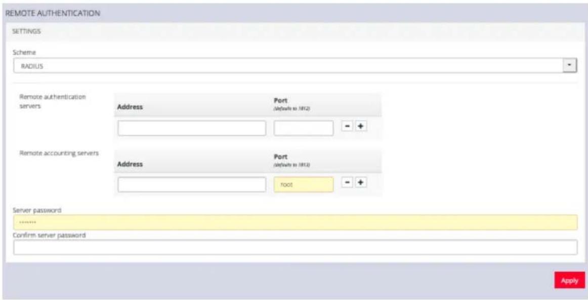
text_image
REMOTE AUTHENTICATION SETTINGS Scheme RADIUS Remote authentication servers Address Port (defaults to MRL2) - + Remote accounting servers Address Port (defaults to MRL2) root + Server password MRL2 Confirm server password ApplyCONFIGURE MENU 103

opengear
-
Add the Address and optionally the Port of the RADIUS authentication server to query.
-
Add the Address and optionally the Port of the RADIUS accounting server to send accounting information to.
-
Add and confirm the Server password, also known as the RADIUS Secret.
Note: Multiple servers can be added. The RADIUS subsystem queries them in a round-robin fashion.
To provide group membership, RADIUS needs to be configured to provide a list of group names via the Framed-Filter-Id attribute. The following configuration snippet shows how this can be configured for FreeRADIUS:
operator1 Auth-Type := System
Framed-Filter-ID = ":group_name=west_coast_admin,east_coast_user:"
Note: The Framed-Filter-ID attribute must be delimited by the colon character.
To configure TACACS+:
- Under CONFIGURE > USER MANAGEMENT > Remote Authentication, select TACACS+ from the Scheme drop-down menu.
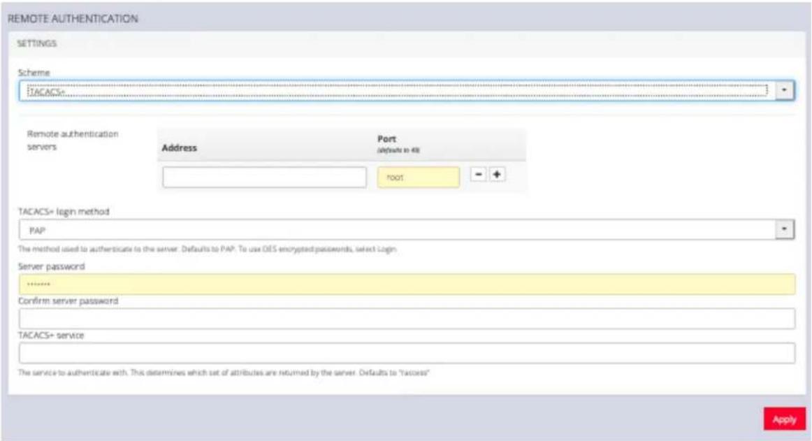
text_image
REMOTE AUTHENTICATION SETTINGS Scheme TACACS+ Remote authentication servers Address Port (Defaults to 48) FOOT TACACS+ login method PAP The method used to authenticate to the server. Defaults to PAP. To use OES encrypted passwords, select Login Server password ...... Confirm server password TACACS+ service The service to authenticate with. This determines which set of attributes are returned by the server. Defaults to "access" Apply- Add the Address and optionally the Port of the TACACS+ authentication server to query.
- Select the Login Method. PAP is the default method. However, if the server uses DES-encrypted passwords, select Login.
- Add and confirm the Server password, also known as the TACACS+ Secret.
- Add the Service. This determines the set of attributes sent back by the TACACS+ server
Note: Multiple servers can be added. The TACACS+ subsystem queries them in a round-robin fashion.
user = operator1 {
    service = raccess {
    groupname = west_coast_admin, east_cost_user
    }
}
CONFIGURE MENU 105
To do this with Cisco ACS, see Setting up permissions with Cisco ACS 5 and TACACS+ on the Opengear Help Desk.
RemoteLocal for AAA Server
CONFIGURE > USER MANAGEMENT > Remote Authentication
CONFIGURE > USER MANAGEMENT > Local Users
RemoteLocal authentication allows users to be authenticated locally if they don't exist on the AAA server so that users can still access any consoles that are required to be accessed.
A RemoteLocal alert banner ensures all users are made aware that if the RemoteLocal policy is selected their local users will not be accessible.
If a RemoteDownLocal policy is selected and the AAA server is contactable, then local authentication won't be used.
⚠️ You are using a remote authentication server with a RemoteDownLocal policy. Ensure that users also exist on that server in order to sign in.
Note: This feature is backwards compatible with previous versions of software (the rest api version is unchanged).
Change Authentication Policy
Changing the Authentication policy is simple.

opengear
- Navigate to CONFIGURE > USER MANAGEMENT > Remote Authentication.
- Ensure the required protocol mode is selected (TACACS+, RADIUS, LDAP).
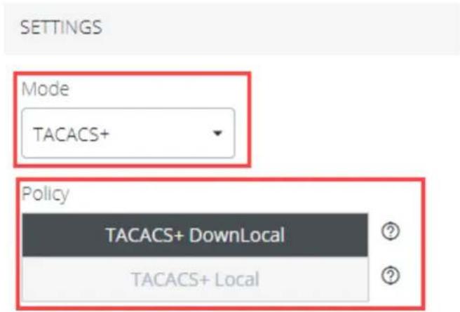
text_image
SETTINGS Mode TACACS+ Policy TACACS+ DownLocal TACACS+ Local- Select the authentication policy you require (DownLocal or Local).
- Click Apply. The policy change is confirmed by a green confirmation banner.

text_image
Details saved successfullyAuthentication Scenarios
The following example shows RADIUS protocol mode, but the behavior is the same for other protocols such as TACACS+ or LDAP.
- User does not exist:
- When using RemoteLocal authentication for all types of remote servers, if remote authentication fails because the user does not exist on the remote AAA server, the OM device will attempt to authenticate the user using a local account as per a regular local log in.
| CONFIGURE MENU 108 |
- Remote Server Down / Unreachable:
- If the remote AAA server is unreachable or down, the OM device tries to authenticate the user using a local account as per a regular local log in.
- Remote server is up, but incorrect credentials:
- The user is denied access. Warnings indicate that RemoteLocal is enabled.
Local Password Policy
CONFIGURE > USER MANAGEMENT > Local Password Policy
A Password Complexity policy allows network administrators to implement and enforce a password policy that meets the customers' security standards for local users (including root). This functionality enables administrators to mandate the setting of complex passwords thus making it difficult for malicious agents to succeed in password attacks.
Enabling this feature will:
• Enforce the use of complex passwords so as to improve security.
- Schedule expiry of passwords to enforce regular password updates.
Note: Password policy such as complexity and expiry can only be configured by an administrator. Password requirements are applied to all accounts.
Tip: Password policy may be enabled and configured via the web-ui, rest-api and ogcli. The password policy also applies to underlying CLI tools.
Set Password Complexity Requirements
CONFIGURE > USER MANAGEMENT > Local Password Policy
Note: Some password complexity rules are required, other rules are optional. Optional rules can be selected by clicking on the relevant check box.
See also "Password Policy Implementation Rules" on page 113
To set the password complexity requirements:
- Navigate to CONFIGURE > USER MANAGEMENT > Local Password Policy.
-
Click the Enforced button to implement the password complexity policy (the policy is not activated until the Apply button is clicked).
-
Enter the information required to form the password complexity rules to comply with your company policy:
• Password cannot be a palindrome (required)
• Minimum length (required)
- Must contain an upper case letter (optional)
- Must contain a numeric character (optional)
- Must contain a special character (non-alphanumeric eg. e.g. #,\$,%)
• Disallow user names in passwords (optional)
See "Password Policy Implementation Rules" on page 113
- Click the Apply button to activate the password complexity policy.
Set Password Expiration Interval
CONFIGURE > USER MANAGEMENT > Local Password Policy
See also "Password Policy Implementation Rules" on the next page
Password Expiration schedules the expiry of passwords to enforce regular password updates. When this feature is applied and a password becomes expired, an expired password prompt is displayed at log-in.
Note: The Password Expiration policy affects local passwords only and does not apply to remote authentication modes.
To set the password expiration interval:
- Navigate to CONFIGURE > USER MANAGEMENT > Local Password Policy.
- Click the Enabled button to implement the password expiration policy (the policy is not activated until the Apply button is clicked).
- Input a number to represent the desired number of days between mandatory password updates. The default time is 90 days and the minimum is 1 day.
- Click the Apply button to activate the password interval policy.
Password Policy Implementation Rules
| Rule Policy | |
| Expiry Rules The expiry time is measured in number of whole days. When the expiry period is reached users are required to update their password on their next login. The default expiry period is 90 days and the minimum is one (1) day. | |
| Complexity Rules | The password cannot be a palindrome (this requirement cannot be disabled except by disabling password complexity entirely). (A palindrome is a word or other sequence of characters that reads the same backward as forward, such as am or racecar). |
| The minimum length (enforced) must be at least 8 characters (this requirement cannot be disabled except by disabling password complexity entirely). | |
| The password should contain at least one upper case alpha-betic character (enabled or disabled separately). | |
CONFIGURE MENU 113
| The password must contain at least one numeric character (enabled/disabled separately). | |
| The password should contain at least one special character #,$,%) (enabled/disabled separately). | |
| The password cannot contain your user-name. | |
| Complexity requirements will apply when a user next tries to update their password. | |
| An administrator can force the expiry of a users password by running the ogCLI command passwd --expire {username} to force a user to change their password. | |
| The operationsogadduser, ogpasswd and ogsshaddsshkey have been removed. You should instead use ogCLI for these operations. |
| CONFIGURE MENU 114 |
Services
CONFIGURE > SERVICES
The CONFIGURE > SERVICES menu lets you manage services that work with the OPERATIONS MANAGER.
HTTPS Certificate
CONFIGURE > SERVICES > HTTPS Certificate
The OPERATIONS MANAGER ships with a private SSL Certificate that encrypts communications between it and the browser.
To examine this certificate or generate a new Certificate Signing Request, select CONFIGURE > SERVICES > HTTPS Certificate. The details of the Current SSL Certificate appear.
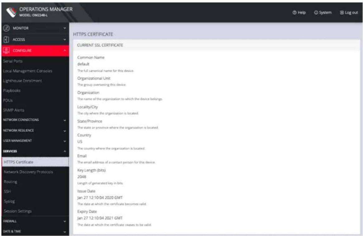
text_image
OPERATIONS MANAGER MODEL: OM2248-L MONITOR ACCESS CONFIGURE Serial Ports Local Management Consoles Lighthouse Enrollment Playbooks POUs SNMP Alerts NETWORK CONNECTIONS NETWORK RESILIENCE USER MANAGEMENT SERVICES HTTPS Certificate Network Discovery Protocols Routing SSH Syslog Session Settings FIREWALL DATE & TIME HTTPS CERTIFICATE CURRENT SSL CERTIFICATE Common Name default The full canonical name for this device. Organizational Unit The group overshending this device. Organization The name of the organization to which the device belongs. Locality/City The city where the organization is located. State/Province The state or province where the organization is located. Country US The country where the organization is located. Email The email address of a contact person for this device. Key Length (bits) 2048 Length of generated key in bits. Issue Date Jan 27 12:10:04 2020 GMT The date at which the certificate becomes valid. Expiry Date Jan 27 12:10:04 2021 GMT The date at which the certificate ceases to be valid.Below this listing is a Certificate Signing Request form, which can be used to generate a new SSL certificate.
CONFIGURE MENU 116
CERTIFICATE SIGNING REQUEST
Common Name
The full canonical name for this device
Organizational Unit
The group answering this device
Organization
The name of the organization to which the device belongs
Locality/City
The city where the organization is located
State/Province
The state or province where the organization is located
Country
United Arab Emirates
The country where is the organization is located
root
The email address of a contact person for this device
Key Length (bits)
21548
Length of generated keep-in bits
Challenge Password
*****
An optional (dependent on CA) password
Confirm Password
Confirmation of the challenge password
Private Key File
Browse... No file selected
A private key to use after generating the CSR (optional)
Apply
Network Discovery Protocols
CONFIGURE > SERVICES > Network Discovery Protocols
The OPERATIONS MANAGER displays LLDP/CDP Neighbors when enabled for a connection. See CONFIGURE > SERVICES > Network Discovery Protocols to enable/disable.
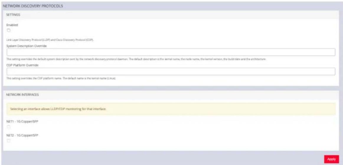
text_image
NETWORK DISCOVERY PROTOCOLS SETTINGS Enabled Link Layer Discovery Protocol (LLDP) and Data Discovery Protocol (CDP). System Description: Override This setting overrides the default system description sent by the network discovery protocol daemon. The default description is the kernel name, the mode name, the kernel version, the build date and the architecture. CDIP Platform: Override This setting overrides the CDP platform name. The default name is the kernel name (.linux) NETWORK INTERFACES Selecting an interface allows LLDP/CDIP monitoring for that interface. NET1 - 1G Copper/SFP NET2 - 1G Copper/SFP ApplyThe CONFIGURE > SERVICES > Network Discovery Protocols > LLDP/CDP NEIGHBORS page allows you to enable this service by clicking the Enable checkbox. You can set a System Description that overrides the default system description sent by the network discovery protocol daemon. The default description is the kernel name, the node name, the kernel version, the build date and the architecture. You can also enter a value in the CDP Platform Override to override the CDP platform name. The default name is the kernel name (Linux). Select one or more checkboxes in the NETWORK INTERFACES section of the page and click Apply.
CONFIGURE MENU 118
Routing
CONFIGURE > SERVICES > Routing
You can enable routing protocols on this page. Select CONFIGURE > SERVICES > Routing page.
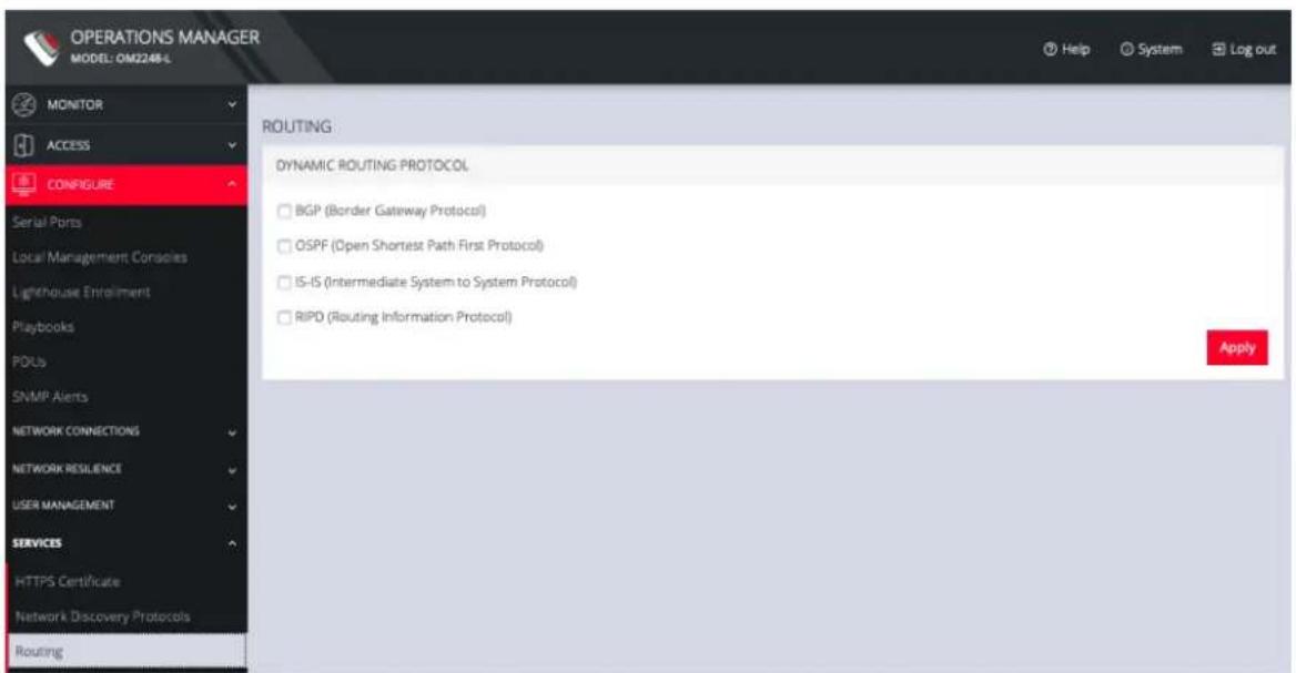
text_image
OPERATIONS MANAGER MODEL: OM2248-L MONITOR ACCESS CONFIGURE Serial Ports Local Management Consoles Lighthouse Enrollment Playbooks PDUs SNMP Alerts NETWORK CONNECTIONS NETWORK RESILIENCE USER MANAGEMENT SERVICES HTTPS Certificate Network Discovery Protocols Routing ROUTING: DYNAMIC ROUTING PROTOCOL BGP (Border Gateway Protocol) OSPF (Open Shortest Path First Protocol) IS-IS (Intermediate System to System Protocol) RIPD (Routing Information Protocol) ApplySelect any of the following and click the Apply button:
• BGP (Border Gateway Protocol)
- OSPF (Open Shortest Path First Protocol)
• IS-IS (Intermediate System to System Protocol)
• RIPD (Routing Information Protocol)
SSH
CONFIGURE > SERVICES > SSH
To modify the port used for connecting to serial consoles via SSH, click CONFIGURE > SERVICES > SSH.
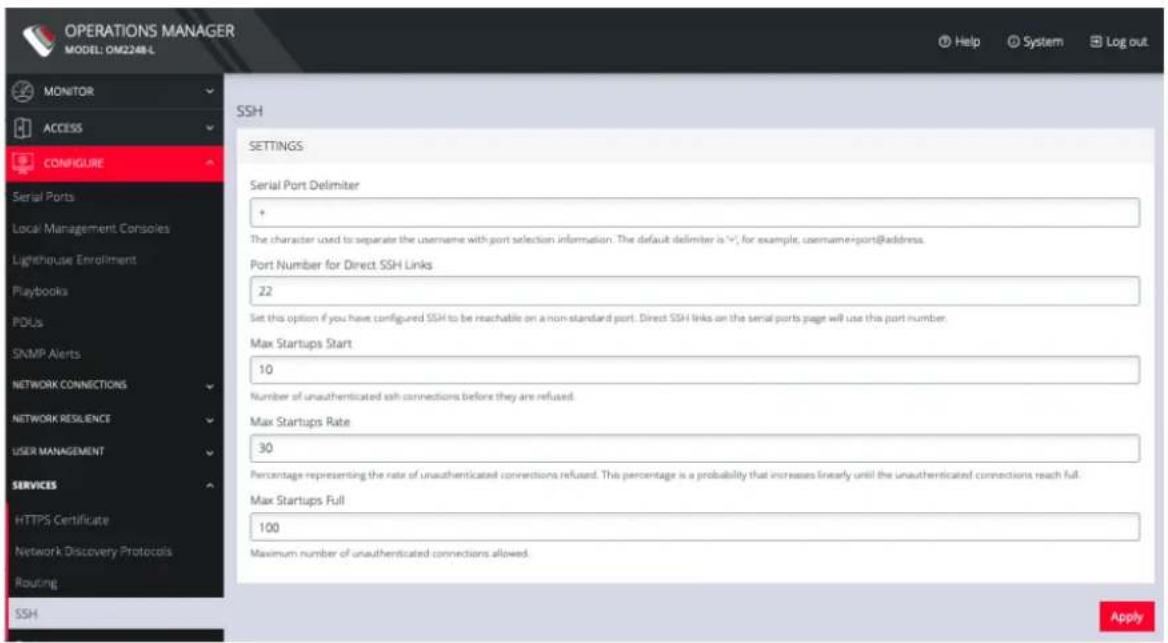
text_image
OPERATIONS MANAGER MODEL: DM2248-L MONITOR ACCESS CONFIGURE SSH SETTINGS Serial Port Delimiter + The character used to separate the username with port selection information. The default delimiter is 1/2, for example, username=port@address. Port Number for Direct SSH Links 22 Set this option if you have configured SSH to be reachable on a non-standard port. Direct SSH links on the serial ports page will use this port number. Max Startups Start 10 Number of unauthenticated ssh connections before they are refused. Max Startups Rate 30 Percentage representing the rate of unauthenticated connections refused. This percentage is a probability that increases linearly until the unauthenticated connections reach full. Max Startups Full 100 Maximum number of unauthenticated connections allowed. SNMP Alerts NETWORK CONNECTIONS NETWORK RESILIENCE USER MANAGEMENT SERVICES HTTPS Certificate Network Discovery Protocols Routing SSH ApplyThis page also lets you set the delimiting character used to separate the username with port selection information. The default delimiter is a plus sign (+). For example, username+port@address.
You can change more values on this page.
- Max Startups Start, the number of unauthenticated connections before they are refused.
- Max Startups Rate is a percentage that represents the rate of unauthenticated connections refused. This percentage is a probability that
CONFIGURE MENU 120

opengear
increases linearly until the unauthenticated connections reach full.
- Max Startups Full is the number of unauthenticated connections allowed.
Unauthenticated SSH to Console Ports
Configure > Services > SSH
The Unauthenticated SSH Access feature provides the option to access console ports (using TCP high ports) by establishing per-port SSH connection between a console and serial ports at a remote device. This allows a single step log-in and avoids the necessity for two log-ins to reach a remote end device within secure, closed networks.
Usually, you would need to authenticate on the Opengear appliance, followed by any log in to a device you are connecting to via the serial port.
When unauthenticated access is enabled SSH is available to all serial ports on the device without requiring a password.
Note: Unauthenticated access can be used with or without IP aliases for serial ports.
Caution: For security, Unauthenticated SSH should only be used when operating within a trusted, closed network, for example within a lab. There is a security risk in allowing any kind of unauthenticated access to serial ports and any terminals connected to them.
Enable Unauthenticated SSH
Authenticated or Unauthenticated access is determined via a global configuration option. Unauthenticated access to individual ports is achieved by command such as ssh -p 300X user@
Enable SSH
Note: This feature may be enabled using the default settings without the need for configuration.
- Open the SSH form, Configure > Services > SSH > SSH (form).
- Complete the SSH form (if this is the first time Unauthenticated SSH has been used), a description of the input data is provided at Properties and Settings in this topic.
- When required, enable the Unauthenticated SSH feature by clicking the Enabled button.
Note: Unauthenticated access to all serial ports will be available through SSH on TCP port 3000+ or Serial Port IP aliases.
Enable/Disable
Enabling or disabling this feature is done in the user interface.
To enable the feature click on the Enabled button then click the Apply button. The feature is enabled immediately and a pop-up will confirm that the feature is enabled.
Note: Clicking the Apply button saves any changes you have made to the SSH form. A Details Saved banner confirms that the changes have been saved.
To disable the feature click on the Disabled button then click the Apply button.
There is no confirmation pop-up when the feature is disabled.
Connecting Directly to Serial Ports
For ports that have been configured with the SSH access service, you can connect directly to a port and start a session, bypassing the chooser, by using one of the four conventions described in the following:
| Convention Example | |
| Use a network client to connect to the service network Base Port + serial port number. | # SSH to serial port 1 by TCP portssh -p 3001 -l operator 70.33.235.190In this example, the SSH base port is TCP port 3000, so SSH to TCP port 3001 directly connects you to serial port 1 |
| SSH to the Opengear device, log in adding :portXX to your username (e.g. root:port01 or operator:port01) | # SSH to serial port labelled Routerssh -l operator:Router 70.33.235.190 |
| SSH to the Opengear device, log in adding the :port-label to your username (e.g. root:Router or operator:Router) | # SSH to serial port 1 by port namessh -l operator:port01 70.33.235.190 |
| Configure per-port IP aliases | |
CONFIGURE MENU 124
Note: For additional reading on connecting to serial ports see:
https://opengear.zendesk.com/hc/en-us/articles/216373543-Communicating-with-serial-port-connected-devices
Note: Serial ports in the Local Console and Disabled ports modes are not available for SSH connection.
Feature Persist
If the device has an active console session after closing pmshell, connecting to the device again will resume the session and you are not prompted for the device password.
Properties and Settings
| Property Definition/Range | |
| Serial Port Delimiter | A character that separates the User name and port selection information. The default value is the + character.Default is '+', maximum length is 1.The prohibited characters are '\, ' '', '', '', &=' and '#'.Source: schemarequired ssh_delimiter: string (default = "+"; minimum = 1; maximum = 1; validator = ("ssh_url_ |
CONFIGURE MENU 125
| delimiter”),Source: validatorif (strlen(v) != 1) valid = 0;else if (v[0] == "\") valid = 0;else if (v[0] == ""') valid = 0;else if (v[0] == ''') valid = 0;else if (v[0] == ''') valid = 0; // breaks sshd_configelse if (v[0] == '=') valid = 0; // breaks sshd_configelse if (v[0] == '#') valid = 0; // breaks sshd_configelse if (!isprint(v[0])) valid = 0;else {valid = 1;} | |
| Port Number for Direct SSH Links | This port number will be used for direct SSH links on the serial ports page. Set this option if you have configured SSH to be reachable on a non-standard port. |
| Max Startups Start | The number of connections pending authentication before new connections begin to be refused.Required start: int (minimum = 1; default = 10) |
CONFIGURE MENU 126
| Max Startups Full | The number of connections pending authentication before all new connections are refused. Required full: int (minimum = 1; default = 100) |
| Max Startups Rate | This is the percentage rate at which new connections are refused once the Max Startups value is reached. The rate is increased to 100% at Ma Startup Full. Required rate: int (minimum = 1; maximum = 10 default = 30), The rate at which connections are refused randomly begins at max startup rate and increases linearly until the number of connections pending authentication reach max startups full, in which case 100% of new connections are refused. |
| Unauthenticated Access to Serial Ports | This is the feature Enable/Disable button. |
CONFIGURE MENU 127
Syslog
CONFIGURE > SERVICES > Syslog
Administrative users can specify multiple external servers to export the syslog to via TCP or UDP.
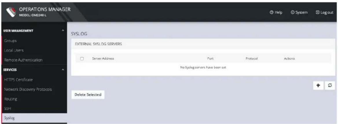
text_image
OPERATIONS MANAGER MODEL: CM2248-L USER MANAGEMENT Groups Local Users Remote Authentication SERVICES HTTPS Certificate Network Discovery Protocols Routing SSH Syslog SYSLOG EXTERNAL SYSLOG SERVERS Server Address Port Protocol Actions No Syslog servers have been set Delete SelectedThis page lists any previously added external syslog servers. To add a new one,
- Navigate to CONFIGURE > SERVICES > Syslog.
- Click the Plus button. The External Syslog Servers form appears.
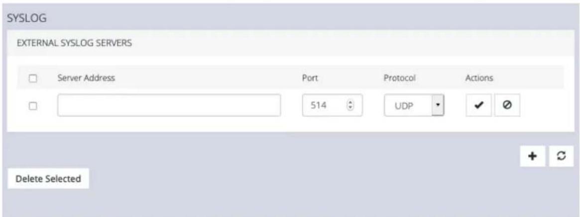
text_image
SYSLOG EXTERNAL SYSLOG SERVERS Server Address Port Protocol Actions 514 UDP Delete SelectedCONFIGURE MENU 128

opengear
-
Enter the Server Address.
-
Enter the Protocol, either UDP or TCP.
-
Enter the correct Port. If no port is entered, UDP defaults to port 514 and TCP defaults to 601.
-
Click Apply.
To edit an existing syslog server, click the Edit button under Actions. Delete a server by clicking the Delete button or the checkbox next to multiple servers and the Delete Selected button.
Remote Syslog
Configure > Services > Syslog
Configure > Services > Syslog > Create Syslog Server
Configure > Services > Syslog > Edit Syslog Server
Configure > Services > Syslog > Global Serial Port Settings
Configure > Serial Ports > Edit Serial Port
The Remote Syslog facility provides the flexibility to specify a Remote Syslog server so that you can redirect console serial port logs to the Remote Syslog server so as to provide a central (and regional) repository where you can view the port-related activity. When remote logs are being received, local logs continue to be recorded.
Devices in a network can produce thousands of log entries; due to the number of logs occurring each hour, users demand the ability to configure the facility and severity for console port logs. The Remote Syslog collector can be configured so as to categorize and prioritize the logs appropriately thus allowing you to easily identify issues as they arise.
The Remote Syslog server provides the flexibility to:
- Analyze logs centrally.
• Monitor for suspicious activities.
• Collect and view analytics (for example, Splunk).
Requirements
IP address of syslog server
Syslog server port number
CONFIGURE MENU 130
Set Logging Levels For Remote Syslog Server
Local Log Level limits the Syslog information being logged. Any log entry with a value equal or greater than the level specified in the config is sent to the remote server.
Ensure Port Logging is Set to the Required Level
- Navigate to the Serial Ports page and enable port logs through the serial port (Con-
figure > Serial Ports) - For the serial port number you have selected, click the Edit Serial Ports button in the Actions column.
- Navigate to Logging Settings and select the required logging level.
- Click the Apply button. The change will be applied within a few seconds.
Set Global Serial Port Settings
Navigate to: Configure > Services > Syslog > Global Serial Port Settings
- In the Global Serial Ports tab
i. Select the required Facility.
ii. Select the required Severity.
Note: See the tables below for definitions of Facility and Severity.
- Click the Update button and wait for the update confirmation banner:
The Syslog will log only those entries of the nominated event type.
Edit or Delete an Existing Syslog Server
Configure > Services > Syslog > Edit Syslog Server
CONFIGURE MENU 131

opengear
-
In the Configure > Services > Syslog tab click on the IP address of the target server. The Edit Syslog Server tab is opened for editing.
-
You can delete a server by clicking the Delete button at the top right of the Edit tab page.
Syslog Terminology
Syslog logging terminology used in setting Facility and Severity of the Syslog.
Create Syslog Server Tab - Field Definitions
Page location: Configure > Services > Syslog > Create Syslog Server
| Field Definition | |
| Description Unique, familiar text description or name given to this syslog server that users will recognize. | |
| Server Address The | IP address of the remote syslog server you are using for logging. |
| Protocol Click to select the required protocol for data transmission to the syslog server. | |
| Port The Remote Syslog Server IP address. | |
| Minimum Log Severity Level | Log entries with a value equal or greater than the level specified are sent to the remote server. |
| Send Serial Port Logs | Click to enable serial port logging. |
| Create Button | Click to initiate the remote syslog, wait for confirmation banner. |
| CONFIGURE MENU | 132 |
Syslog Facility Definitions
| Facility Definition | |
| Kern Kernel messages | |
| User User-level messages | |
| Mail Mail system | |
| Daemon System daemons | |
| Auth Security/authentication messages | |
| Syslog Messages generated internally by syslogd | |
| Ipr Line printer subsystem | |
| News Network news subsystem | |
| uucp UUCP subsystem | |
| Cron Clock daemon | |
| Authpriv | Security/authentication messages |
| ftp | FTP daemon |
| Local | Locally used facilities |
| CONFIGURE MENU | 133 |
Syslog Severity Definitions
| Severity Definition | |
| 0- Emergency System | is unusable. |
| 1 - Alert Action must | be taken immediately. |
| 2 - Critical Critical conditions. | |
| 3 - Error Error conditions. | |
| 4 - Warning Warning | conditions. |
| 5 - Notice Normal but | significant conditions. |
| 6 - Info Informational | messages |
| 7- Debug Debug-level | messages |
Session Settings
SETTINGS > SERVICES > Session Settings
To modify Web and CLI session settings navigate to the SETTINGS > Services > Session Settings page.
• Web Session Timeout: This value can be set from 1 to 1440 minutes.
- CLI Session Timeout: This value can be set from 1 to 1440 minutes or set it to 0 to disable the timeout. Changes take effect the next time a user logs in via the CLI.
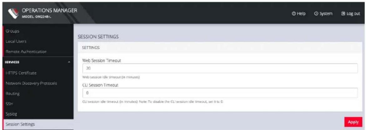
text_image
OPERATIONS MANAGER MODEL: 0M2248-L Groups Local Users Remote Authentication SERVICES HTTPS Certificate Network Discovery Protocols Routing SSH Syslog Session Settings SESSION SETTINGS SETTINGS Web Session Timeout 20 Web session idle timeout (in minutes) CLI Session Timeout 0 CLI session idle timeout (in minutes). Note: To disable the CLI session idle timeout, set it to 0. ApplyCONFIGURE MENU 135
Firewall
CONFIGURE > FIREWALL
The CONFIGURE > FIREWALL menu lets you configure Firewall Management, Interzone Policies, and Services.
Firewall Management
CONFIGURE > FIREWALL > Management
To change firewall management settings navigate to CONFIGURE > FIREWALL > Management.
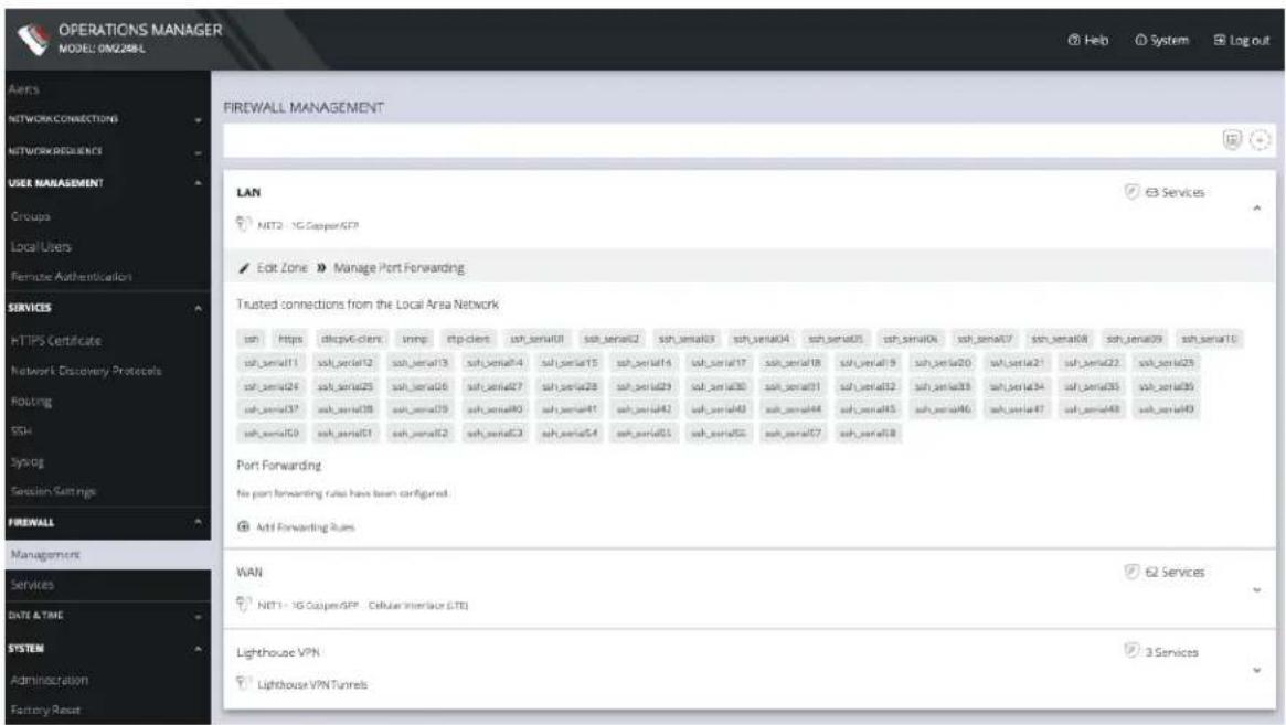
text_image
OPERATIONS MANAGER MODEL: DM2288L Aero NETWORK CONNECTIONS NETWORK RECIENCE USER MANAGEMENT Groups Local Users Remote Authentication SERVICES HTTPS Certificate Network Discovery Protocols Routing SSH Syslog Session Settings FIREWALL Management Services DATE & TIME SYSTEM Administration Factory Reset FIREWALL MANAGEMENT LAN NIT2 - 1G CopperSFP Edit Zone > Manage Port Forwarding Trusted connedions from the Local Area Network ssh https dikpv6-clers urlmp ftp-clers ssh_serial01 ssh_serial02 ssh_serial03 ssh_serial04 ssh_serial05 ssh_serial06 ssh_serial07 ssh_serial11 ssh_serial12 ssh_serial13 ssh_serial14 ssh_serial15 ssh_serial16 ssh_serial17 ssh_serial18 ssh_serial19 ssh_serial20 ssh_serial21 ssh_serial22 ssh_serial23 ssh_serial24 ssh_serial25 ssh_serial26 ssh_serial27 ssh_serial28 ssh_serial29 ssh_serial30 ssh_serial31 ssh_serial32 ssh_serial33 ssh_serial34 ssh_serial35 ssh_serial36 ssh_serial37 ssh_serial38 ssh_serial39 ssh_serial40 ssh_serial41 ssh_serial42 ssh_serial43 ssh_serial44 ssh_serial45 ssh_serial46 ssh_serial47 ssh_serial48 ssh_serial49 ssh_serial50 ssh_serial51 ssh_serial52 ssh_serial53 ssh_serial54 ssh_serial55 ssh_serial56 ssh_serial57 ssh_serial58 Port Forwarding: No port forwarding rules have been configured. Add Forwarding Rules WAN NET1 - 1G CopperSFP - Cellular Interface (LTD) Lighthouse VPN Lighthouse VPN Tunnels 62 Services 3 ServicesYou can expand each zone by clicking the Expand arrow on the right. Once expanded, you can click Edit Zone to change settings for a particular zone.
CONFIGURE MENU 137
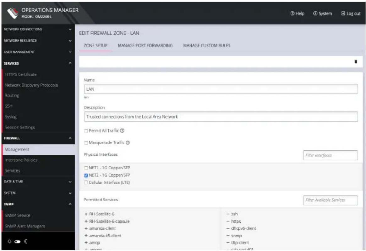
text_image
OPERATIONS MANAGER MODEL: ON2248-L NETWORK CONNECTIONS NETWORK RESILIENCE USER MANAGEMENT SERVICES HTTPS Certificate Network Discovery Protocols Routing SSH Syslog Session Settings FIREWALL Management Interzone Policies Services DATE & TIME SYSTEM SNMP SNMP Service SNMP Alert Managers EDIT FIREWALL ZONE - LAN ZONE SETUP MANAGE PORT FORWARDING MANAGE CUSTOM RULES Name LAN lan Description Trusted connections from the Local Area Network Permit All Traffic Mosquerade Traffic Physical Interfaces Filter Interfaces NET1 - 1G Copper/SFP NET2 - 1G Copper/SFP Cellular Interface (LTE) Permitted Services Filter Available Services + RH-Satellite-6 - ssh + RH-Satellite-6-capsule - https + amanda-client - dhcpv6-client + amanda-kS-client - snmp + amqp - ttp-client + amqo5 - ssh serial01The Edit Zone page has three tabs. The ZONE SETUP page allows you to:
- Modify the Name of the zone
- Add a Description for this zone
- Permit all Traffic
• Masquerade Traffic - Select Physical Interfaces
- Manage Permitted Services by clicking on Plus or Minus next to each
Note: You can use the Filter Interfaces and Filter Available Services text boxes to navigate through the lists.
CONFIGURE MENU 138
The MANAGE PORT FORWARDING tab allows you to add, edit, and delete forwarding rules for the particular zone you are editing.
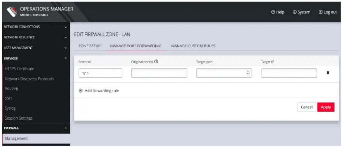
text_image
OPERATIONS MANAGER MODEL: OM2248-L NETWORK CONNECTIONS NETWORK RESILIENCE USER MANAGEMENT SERVICES HTTPS Certificate Network Discovery Protocols Routing SSH Syslog Session Settings FIREWALL Management EDIT FIREWALL ZONE - LAN ZONE SETUP MANAGE PORT FORWARDING MANAGE CUSTOM RULES Protocol Original port(s) Target port Target IP TCP Add forwarding rule Cancel ApplyThe third tab, MANAGE CUSTOM RULES, allows you to add, edit, and delete custom firewall rules for the zone you are editing. These custom rules continue to exist after reboots, upgrades, and power cycles.
These rules are prioritized by the order they are added.

text_image
OPERATIONS MANAGER MODEL: OW2248-L NETWORK CONNECTIONS NETWORK RESILIENCE USER MANAGEMENT SERVICES HTTPS Certificate Network Discovery Protocols Routing SSH Syslog Session Settings FIREWALL Management Interzone Policies EDIT FIREWALL ZONE - LAN ZONE SETUP MANAGE PORT FORWARDING MANAGE CUSTOM RULES All rules will be wrapped as follows: firewall-cmd --permanent --zone=lan --add-rich-rule=RULE CONTENT Description Rule Content ? Add custom rule Cancel ApplyTo add a new custom rule:
| CONFIGURE MENU 139 |
- Click Add custom rule.
- Enter a Description for this rule.
- Enter Rule Content, custom rule content formatted with firewall-cmd syntax.
- Click Apply.
All rules will be wrapped as follows:
firewall-cmd --permanent --zone=lan --add-rich-rule=RULE CONTENT
Additional menu options under CONFIGURE > FIREWALL are Rules, Services, and Zones.
The mainFIREWALL MANAGEMENT page also contains quick links to Add Firewall Service (shield icon on upper right), Add Firewall Zone (plus icon on upper right), and Edit Zones pages (pencil icon in expanded view) for the currently selected zone.
Manage Firewall Rules
Click CONFIGURE > FIREWALL > Services. This opens the SERVICES page with a list of all firewall rules.
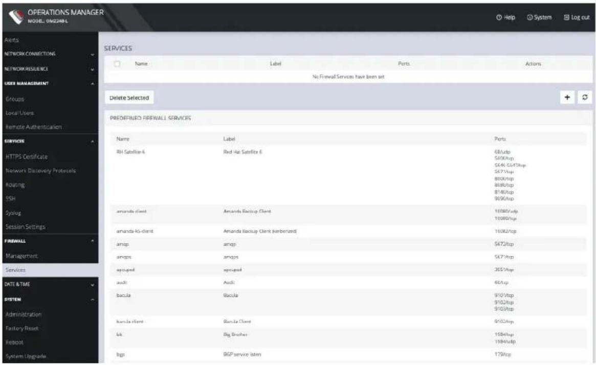
text_image
OPERATIONS MANAGER MODEL: ONZARML Help System Log out Assets NETWORK CONNECTIONS NETWORK RESILENCI USER MANAGEMENT Groups Local Users Remote Authentication SERVICES HTTPS Certificate Network Discovery Protocols Routing SSH Syslog Session Settings FIREWALL Management Services DATE & TIME SYSTEM Administration Factory Reset Reboot System Upgrade SERVICES Name Label Ports Actions No Finwall Services have been set Delete Selected PREDDEFINED FIREWALL SERVICES Name Label Ports RH Satellite 4 Red Hat Satellite 6 68/udp 5600/ftp 5640 GS47/ftp 5671/ftp 8000/ftp 8080/ftp 8140/ftp 9090/ftp amanda client Amanda Backup Client 10880/udp 10880/ftp amanda-k client Amanda Backup Client (kerberized) 10882/ftp amgs amgs 5672/ftp amgs amgs 5673/ftp apoged apoged 3657/ftp audi Audi 66/ftp bacula Bacula 9101/ftp 9102/ftp 9103/ftp bacla client Bacla Client 9102/ftp Lk Big Brother 1584/ftp 1584/ftp bgp BGP service istm 1794/ftpServices can be added, deleted, or edited from this page. Scroll to the bottom of the page to access the Plus button to add a new service.
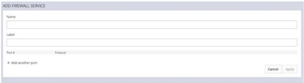
text_image
ADD FIREWALL SERVICE Name Label Port # Protocol + Add another port: Cancel ApplyEnter a Service description and a Zone for the new rule.
Manage Firewall Zones
Click CONFIGURE > FIREWALL > MANAGEMENT.
This opens the ZONES page with a list of all firewall zones.
CONFIGURE MENU 141
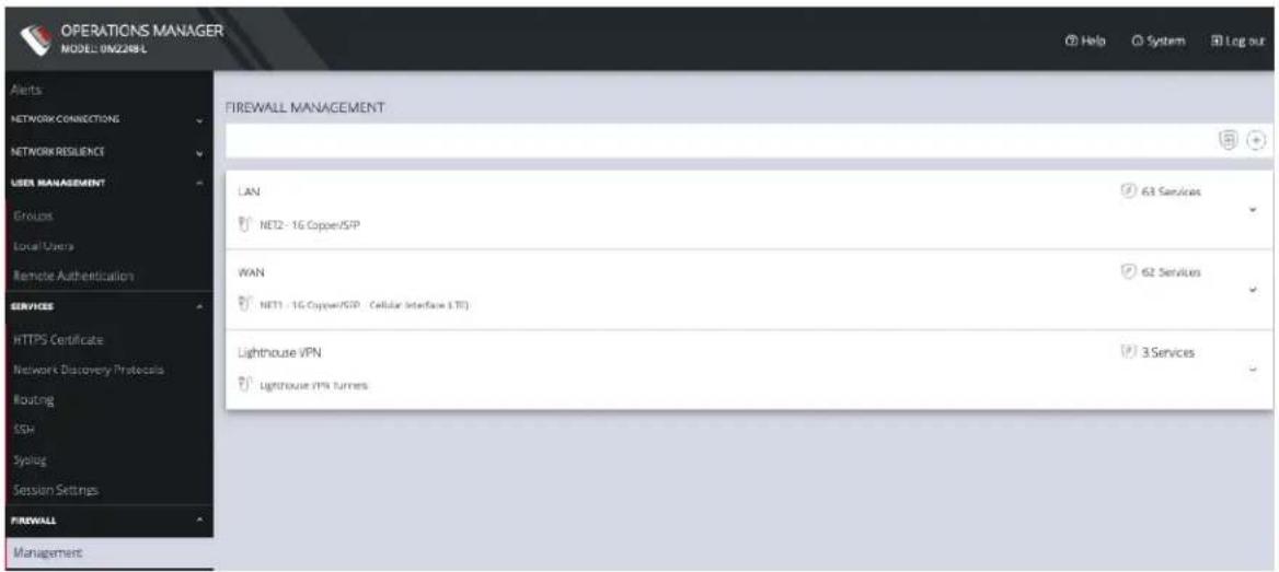
text_image
OPERATIONS MANAGER MODEL: 0M2286L Alerts NETWORK CONNECTIONS NETWORK RESILIENCE USER MANAGEMENT Enrolux Local Users Remote Authentication SERVICES HTTPS Certificate Network Discovery Protocols Routing SSH Synclog Session Settings FIREWALL Management FIREWALL MANAGEMENT LAN NET2 - 1G Copper/SFP WAN NET1 - 1G Copper/SFP ( Cellular Interface LTD ) Lighthouse VPN lighthouse VPN turns 63 Services 62 Services 3 ServicesZones can be added, deleted, or edited from this page. Click the PLUS symbol on the top right of the page to add a new zone.
ADD FIREWALL ZONE
Name
Label
Description
Permit All Traffic

When this option is enabled, all traffic is permitted in this zone. Any rules configured for this zone will have no effect.
Masquerade Traffic

When this option is enabled, traffic through this zone is masqueraded. If you wish to enable masquerading, it should be enabled on the zone bound to the external interface.
Adding an interface to this zone will remove that interface from the zone it is currently in. This may prevent access to the console server until appropriate rules are made for this zone.
Physical Interfaces
□ NET1 - 1G Copper/SFP
□ NET2 - 1G Copper/SFP
□ Cellular Interface (LTE)
Traffic entering on the selected interfaces is in this zone
Cancel
Apply
The NEW FIREWALL ZONE page allows you to:
- Name the zone
- Add a Description for this zone
- Permit all Traffic
• Masquerade Traffic - Select Physical Interfaces
CONFIGURE MENU 143
Interzone Polices
CONFIGURE > FIREWALL > Interzone Policies > Create Interzone Policy
In the Operations Manager, Interzone firewall policy is implemented through Firewalld; this is a zone-based firewall which allows you to define zones and create rules to manage the traffic between the zones.
The firewalld feature provides a dynamically managed firewall with support for network/firewall “zones” to assign a level of trust to a network and its associated connections, interfaces or sources.
The feature allows you to define policies to configure forwarding between zones and can be configured to allow directional forwarding from one or more ingress zones to one or more egress zones.
Rules and filtering may be applied at the zone level. When you add a zone, you select which services are part of that zone. Interzone policy allows these rules and filtering to be applied so as to control the type of traffic allowed to be forwarded.
The default policy, ie. when no zones are added, is that no traffic is forwarded.
Create an Interzone Policy
CONFIGURE > FIREWALL > Interzone Policies > New Interzone Policy
-
Navigate to the Interzone Policies page: CONFIGURE > FIREWALL > Interzone Policies.
-
Click the Add Firewall Policy button, the New Interzone Policy page opens for editing.
-
In the Name field, enter a name that clearly identifies this policy instance to other users.
CONFIGURE MENU 144

opengear
- In the Description field provide a detailed description of this interzone policy (optional).
- Click to check the boxes for each Ingress and Egress zone that is to be included in this policy. You can configure traffic in both directions by selecting both zones in the Ingress and Egress as in indicated by the red arrows in the image below:
Two Directional Traffic Interzone Policy:
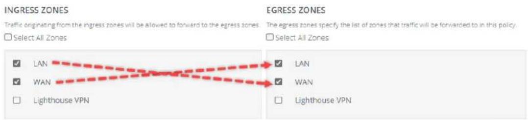
text_image
INGRESS ZONES Traffic originating from the ingress zones will be allowed to forward to the egress zones. Select All Zones EGRESS ZONES The egress zones specify the list of zones that traffic will be forwarded to in this policy. Select All Zones ✓ LAN ✓ WAN ☐ Lighthouse VPN ✓ LAN ✓ WAN ☐ Lighthouse VPNCancel
Apply
Note: Additional zones may be added to the zones list at: CONFIGURE > FIREWALL > Management > New Firewall Zone. Zone customized rules may be edited at CONFIGURE > FIREWALL > Management > Firewall Management.
- Click the Apply button to implement the policy, a green banner will inform you that the policy details are saved successfully. The interzone policy is now in force.
Edit or Delete an Interzone Policy
CONFIGURE > FIREWALL > Interzone Policies > Edit Interzone Policy
- Navigate to the Interzone Policies page: CONFIGURE > FIREWALL > Interzone Policies.
CONFIGURE MENU 145

opengear
- Click the name of the policy you wish to edit (editable policies are identified by red text). The Edit Interzone Policy page opens for editing.
- Edit the policy details to be changed.
- If necessary, change the the Description field to provide a detailed description of the edited interzone policy.
- To delete a policy, click on the Bin widget in the top-right corner of the Edit page.
text_image
Help System Delete Interzone Policy6.
- Click the Apply button to implement the edited policy, a green banner will inform you that the policy details are saved successfully. The edited interzone policy is now in force.
Customized Zone Rules
Customized zone rules may be applied to any zone at CONFIGURE > FIREWALL > Management > Firewall Management: "Firewall Management" on page 137.
Services - Firewall
CONFIGURE > FIREWALL > Services
Managing Firewall Services
Click CONFIGURE > FIREWALL > Services. This opens the SERVICES page with a long list of predefined firewall services.
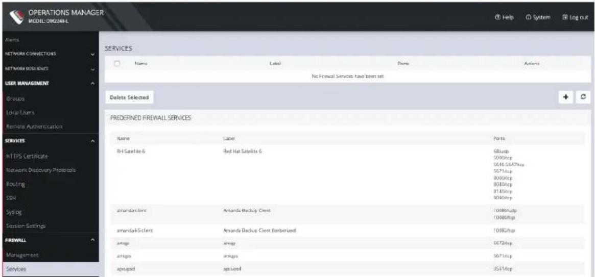
text_image
OPERATIONS MANAGER MODEL:OMZA#HL Alerts NETWORK CONNECTIONS NETWORK RESOURCES USER MANAGEMENT Groups Local Users Remote Authentication SERVICES HTTPS Certificate Network Discovery Protocols Routing SSH Sialog Session Settings: FIREWALL Management Services SERVICES Name Label Ports Actions No Prewall Services have been set Delete Selected PREDEFINED FIREWALL SERVICES Name Label Ports RH Satellite 6 Red Hat Satellite 6 6824p SD003cp SE46-S6479cp SD713cp 8003cp 8080cp 81403cp SD003cp amanda clients Amanda Backup Client 109803cp 109803hp amanda client Amanda Backup Client (berberized) 108673cp amiga amiga 56726p amiga amiga 30716cp apouaged apoured 35316cpServices can be added, deleted, or edited from this page.
Note: Predefined services cannot be edited.
Click the Plus button to add a new service.
CONFIGURE MENU 147
ADD FIREWALL SERVICE
Name
Label
Port #
Protocol
+ Add another port
Cancel Apply
Enter a Name, Label, Port #, and Protocol. Select a Protocol (TCP or UDP) from the Plus button menu. Add more Ports and Protocols as desired and click Apply.
Date & Time
CONFIGURE > DATE & TIME
The Date & Time section of the navigation bar provides a means to
- Set the time zone
• Manually set the correct time and date
• Automatically set the date and time
Time Zone
CONFIGURE > DATE & TIME > Time Zone
To set the time zone:
- Click CONFIGURE > DATE & TIME > Time Zone.
- Select the OPERATIONS MANAGER's time-zone from the Time Zone drop-down list.
- Click Apply.
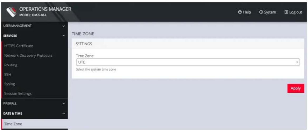
text_image
OPERATIONS MANAGER MODEL: OM2248-L USER MANAGEMENT SERVICES HTTPS Certificate Network Discovery Protocols Routing SSH Syslog Session Settings FIREWALL DATE & TIME Time Zone TIME ZONE SETTINGS Time Zone UTC Select the system time zone ApplyCONFIGURE MENU 150
Manual Settings
CONFIGURE > DATE & TIME > Manual Settings
To manually set the correct time and date:
- Click CONFIGURE > DATE & TIME > Manual Settings.
- Enter the current Date and Time.
- Click Apply.
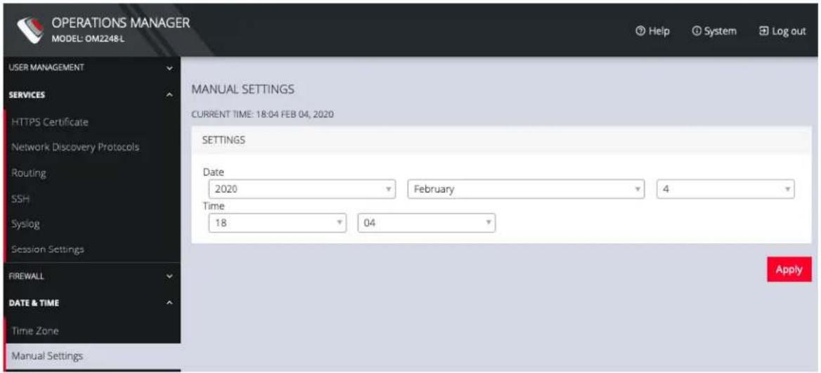
text_image
OPERATIONS MANAGER MODEL: OM2248-L USER MANAGEMENT SERVICES HTTPS Certificate Network Discovery Protocols Routing SSH Syslog Session Settings FIREWALL DATE & TIME Time Zone Manual Settings MANUAL SETTINGS CURRENT TIME: 18:04 FEB 04, 2020 SETTINGS Date 2020 February 4 Time 18 04 ApplyAutomatic Settings
CONFIGURE > DATE & TIME > Automatic Settings
Automatic Setting of the date and time:
- Click CONFIGURE > DATE & TIME > Automatic Settings.
- Click the Enabled checkbox.
- Enter a working NTP Server address in the NTP Server Address field.
- Click Apply.
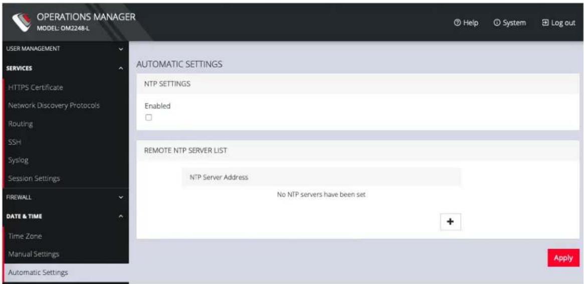
text_image
OPERATIONS MANAGER MODEL: OM2248-L USER MANAGEMENT SERVICES HTTPS Certificate Network Discovery Protocols Routing SSH Syslog Session Settings FIREWALL DATE & TIME Time Zone Manual Settings Automatic Settings AUTOMATIC SETTINGS NTP SETTINGS Enabled REMOTE NTP SERVER LIST NTP Server Address No NTP servers have been set ApplyCONFIGURE MENU 152
System
CONFIGURE > SYSTEM
The CONFIGURE > SYSTEM menu lets you change the OPERATIONS
MANAGER hostname, perform system upgrades, and reset the system.
You can perform a system upgrade when new firmware is released. After specifying the location of the firmware and beginning the process, the system will unavailable for several minutes and then reboot. Unlike a factory reset, users, and other configuration data is maintained.
To perform a system upgrade:
- Navigate to CONFIGURE > System > System Upgrade.
- Select the Upgrade Method, either Fetch image from HTTP/HTTPS Server or Upload Image.
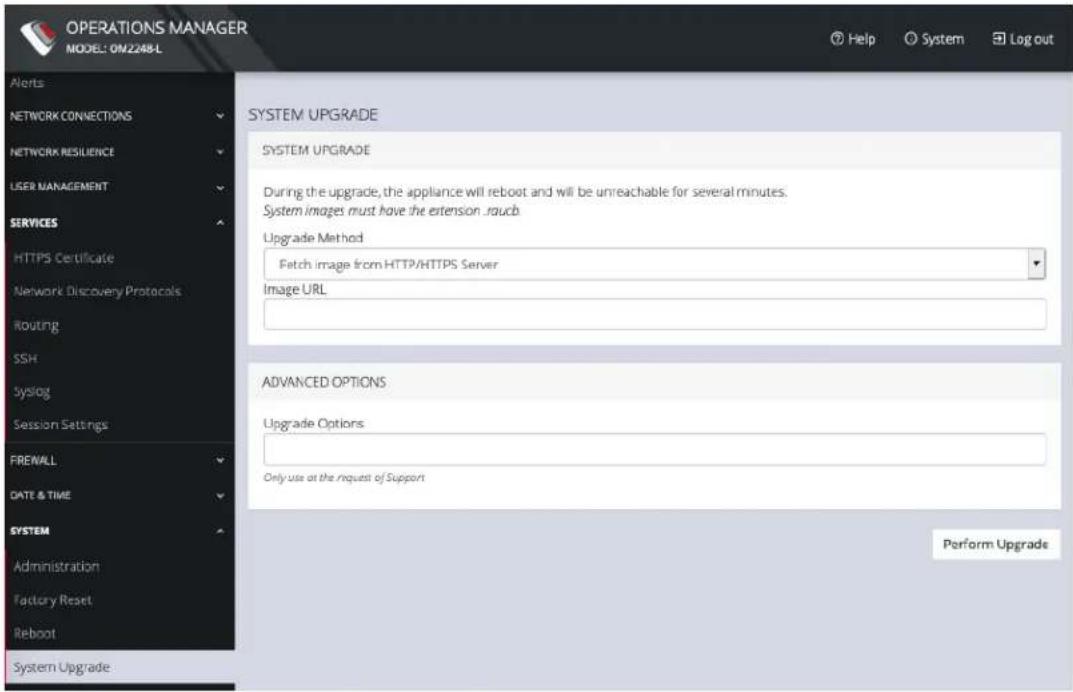
text_image
OPERATIONS MANAGER MODEL: OM2248-L Alerts NETWORK CONNECTIONS NETWORK RESILIENCE USER MANAGEMENT SERVICES HTTPS Certificate Network Discovery Protocols Routing SSH syslog Session Settings FREWALL DATE & TIME SYSTEM Administration Factory Reset Reboot System Upgrade SYSTEM UPGRADE SYSTEM UPGRADE During the upgrade, the appliance will reboot and will be unreachable for several minutes. System images must have the extension .raucb. Upgrade Method Fetch image from HTTP/HTTPS Server Image URL ADVANCED OPTIONS Upgrade Options Only use at the request of Support Perform UpgradeCONFIGURE MENU 153

opengear
If upgrading via Fetch image from HTTP/HTTPS Server:
- Enter the URL for the system image in the Image URL text-entry field.
- Click Perform Upgrade.
Or if upgrading via Upload Image:
- Click the Choose file button.
- Navigate to the directory containing the file.
- Select the file and press Return.
- Click Perform Upgrade.
Note: The Advanced Options section should only be used if a system upgrade is being performed as part of an Opengear Support call.
Once the upgrade has started, the System Upgrade page displays feedback as to the state of the process.
Administration
CONFIGURE > SYSTEM > Administration
To set the hostname, add a contact email, or set a location for the OPERATIONS MANAGER:
- Click CONFIGURE > SYSTEM > Administration.
- Edit the Hostname field.
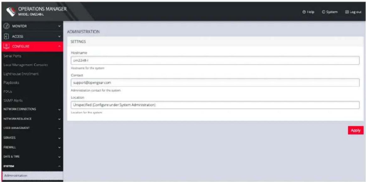
text_image
OPERATIONS MANAGER MODEL: OM2248L MONITOR ACCESS CONFIGURE Serial Ports Local Management Con<|vision_start|> Lighthouse Enroliments Playbooks POUs SNMP Alerts NETWORK CONNECTIONS NETWORK RESILIENCE USER MANAGEMENT SERVICES FIREWALL DATE & TIME SYSTEM Administration ADMINISTRATION SETTINGS Hostname om2248-1 Hostname for the system Contact support@opengaar.com Administration contact for the system Location Unspecified (Configure under System Administration) Location for the system Apply- Click Apply.
CONFIGURE MENU 155
Factory Reset
CONFIGURE > SYSTEM > Factory Reset
You can perform a factory reset, where logs and docker containers are preserved and everything else is reset to the factory default.
To return the OPERATIONS MANAGER to its factory settings:
- Select CONFIGURE > SYSTEM > Factory Reset.
- Read the Factory Reset warning notice.
Warning: This will delete all configuration data from the system and reset all options to the factory defaults. Any custom data or scripts on the device will be lost. Please check the box below to confirm you wish to proceed.
- If you still wish to proceed with the reset, Select the Proceed with the factory reset checkbox.
- Click Reset.
Warning: This operation performs the same operation as the hard factory erase button. This resets the appliance to its factory default settings. Any modified configuration information is erased. You will be prompted to log in and must enter the default administration username and administration password (Username: root Password: default). You will be required to change this password during the first log in.
Reboot
CONFIGURE > SYSTEM > Reboot
To reboot the OPERATIONS MANAGER:
Select CONFIGURE > SYSTEM > Reboot.
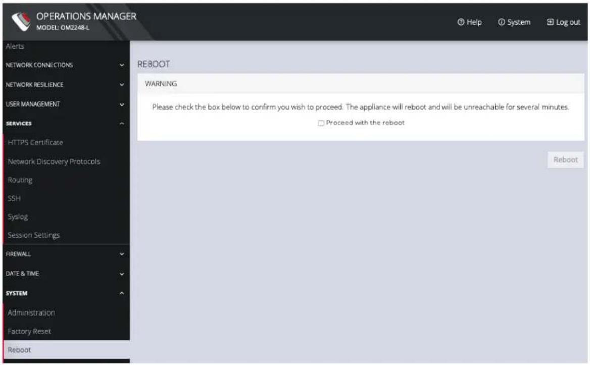
text_image
OPERATIONS MANAGER MODEL: OM2248-L Alerts NETWORK CONNECTIONS NETWORK RESILIENCE USER MANAGEMENT SERVICES HTTPS Certificate Network Discovery Protocols Routing SSH Syslog Session Settings FIREWALL DATE & TIME SYSTEM Administration Factory Reset Reboot REBOOT WARNING Please check the box below to confirm you wish to proceed. The appliance will reboot and will be unreachable for several minutes. □ Proceed with the reboot RebootSelectProceed with the reboot and click Reboot.
CONFIGURE MENU 157
System Upgrade
CONFIGURE > SYSTEM > System Upgrade
You can perform a system upgrade when new firmware is released. After specifying the location of the firmware and beginning the process, the system will unavailable for several minutes and then reboot. Unlike a factory reset, users, and other configuration data is maintained.
To perform a system upgrade:
- Navigate to the CONFIGURE > System > System Upgrade page.
- Select the Upgrade Method, either Fetch image from HTTP/HTTPS Server or Upload Image.
SNMP
CONFIGURE > SNMP
The CONFIGURE > SNMP menu has two options, SNMP Service and SNMP Alert Managers.
SNMP Service
CONFIGURE > SNMP > SNMP Service
Navigate to the CONFIGURE > SNMP > SNMP Service to open the SNMP Service page.
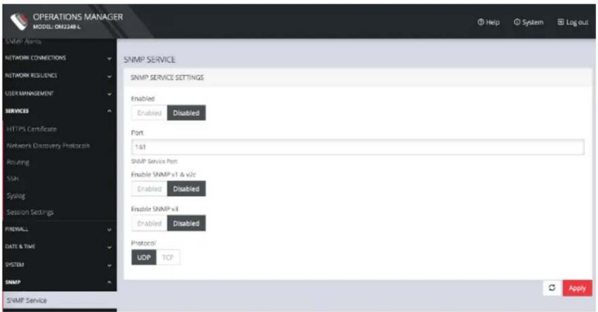
text_image
OPERATIONS MANAGER MODEL: OM2248-L SNMP Alerts NETWORK CONNECTIONS NETWORK RESUENCE USER MANAGEMENT SERVICES HTTPS Certificate Network Discovery Protocols Routing SSH Syslog Session Settings PREFALL DATE & TIME SYSTEM SNMP SNMP Service SNMP SERVICE SETTINGS Enabled Enabled Disabled Port 161 SNMP Service Port Enable SNMP v1 & v2c Enabled Disabled Enable SNMP v3 Enabled Disabled Protocol UDP TCP ApplyThis page allows you to specify which SNMP services to enable. When you click on ENABLED for SNMP V1 & V2 or SNMP V3, a detail form appears where you can add service specific settings.
You can also specify the SNMP Service Port and choose between UDP or TCP for the Protocol.
SNMP Alert Managers
CONFIGURE > SNMP > SNMP Alert Managers
Navigate to CONFIGURE > SNMP > SNMP Alert Managers to open the SNMP Alert Managers page.
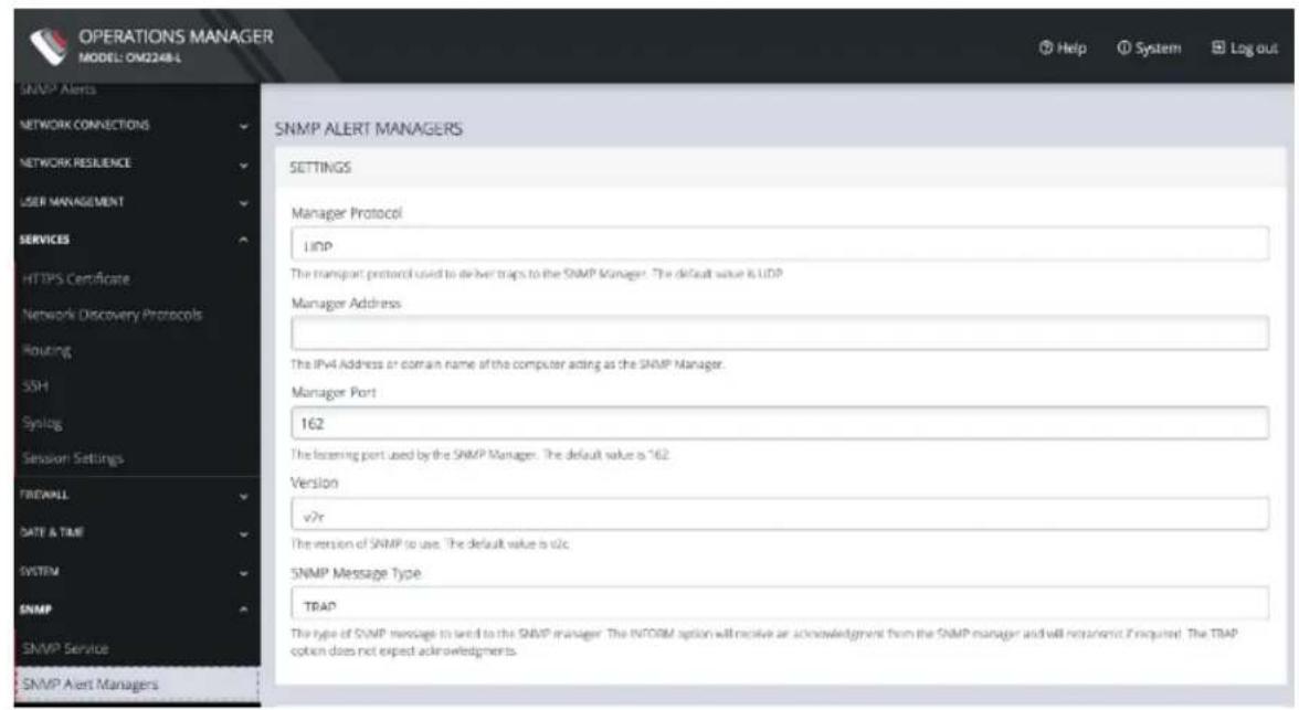
text_image
OPERATIONS MANAGER MODEL: OM2248-L SNMP Alerts NETWORK CONNECTIONS NETWORK RESILIENCE USER MANAGEMENT SERVICES HTTPS Certificate Network Discovery Protocols Routing SSH Synclog Session Settings FIREBALL DATE & TIME SYSTEM SNMP SNMP Service SNMP Alert Managers SNMP ALERT MANAGERS SETTINGS Manager Protocol UDP The transport protocol used to deliver traps to the SNMP Manager. The default value is UDP Manager Address: The IPv4 Address or domain name of the computer acting as the SNMP Manager. Manager Port 162 The licensing port used by the SNMP Manager. The default value is 162 Version v?r The version of SNMP to use. The default value is vlc. SNMP Message Type TRAP The type of SNMP message to lend to the SNMP manager. The INFORM option will receive an acknowledgment from the SNMP manager and will not want it required. The TRAP option does not expect acknowledgments.On this page, you can set the following:
- Manager Protocol: The transport protocol used to deliver traps to the SNMP Manager. The default value is UDP.
- Manager Address: The IPv4 Address or domain name of the computer acting as the SNMP Manager.
- Manager Port: The listening port used by the SNMP Manager. The default value is 162.
- Version: The version of SNMP to use. The default is v2c.
CONFIGURE MENU 161

opengear
- SNMP Message Type: The type of SNMP message to send to the SNMP manager. The INFORM option will receive an acknowledgment from the SNMP manager and will retransmit if required. The TRAP option does not expect acknowledgments.
For SNMP V1 & V2C, you can specify a Community. This is a group name authorized to send traps by the SNMP manager configuration for SNMP versions 1 and 2c. This must match the information that is setup in the SNMP Manager. Examples of commonly used values are log, execute, net and public.
Multiple SNMP Alert Managers
CONFIGURE > SNMP > SNMP Alert Managers > Add New SNMP Alert Manager
The Multiple SNMP Alert Managers feature provides the option to configure more than one SNMP manager. Multiple SNMP Alert Managers can receive trap and inform events that can be used to trigger remedial action; events can be sent to multiple SNMP Alert Managers. The AR functionality sends traps to all configured SNMP Alert Managers for a reaction of type SNMP. Whether you input an IPv6 address or a domain name, the correct protocol needs to be selected.
Create or Delete a New SNMP Manager
To create a new SNMP manager:
- Navigate to Configure > SNMP > SNMP Alert Managers.
- Click the Add New SNMP Manager button (a plus character in the top-right of the window)
- Complete the new SNMP Alert Manager Form as per the Definitions table below.
- Click the Submit button. A banner appears confirming that the new SNMP Manager has been successfully created.
- The new manager appears in the list of SNMP Alert Managers.
- To delete an SNMP manager, click on the IP address of the item to open the Edit SNMP Manager page for that SNMP Manager.
- Click on the Delete SNMP Manager widget in the top-right of the page.
Note: If you would like to use an IPv6 Address, then you need to select either UDP6 or TCP6 from the list of protocols. Whether you input an IPv6 address or a domain name, the correct protocol needs to be selected.
Note: For SNMP V3 TRAPS, an Engine ID will be provided by default if none is specified. This is generated by the snmpd service and can be found in the SNMPD RUNTIME CONF /var/lib/net-snmp/snmpd.conf. Traps will be sent for Alerts added in Configure > SNMP Alerts. Traps will also be sent to all the configured SNMP Alert Managers for a Playbook SNMP Reaction.
New SNMP Alert Manager Page Definitions
| New SNMP Alert Manager Field Definition | |
| Description | The editable Description field allows you to add a description of the SNMP Alert Manager. |
| Server Address The IPv4/IPv6 address or domain name of the computer acting as the SNMP Alert Manager. | |
| Port The listening port used by the SNMP Alert Manager. The default value is 162. | |
| Protocol | The transport protocol used to deliver traps or informs (for SNMP v3). |
| UDP - Speeds up transmissions by enabling the transfer of data before an agreement is provided by the receiving party. | |
| TCP - A commonly used protocol used to transmit data from other higher-level protocols that require all transmitted data to arrive. | |
| UDP6 - Similar to UDP but uses IPv6. | |
| TCP6 - Similar to TCP but uses IPv6. | |
CONFIGURE MENU 164
| Version | The version of SNMP protocol to use. The default value is v2c. For further reading on SNMP versions we suggest:https://en.wikipedia.org/wiki/Simple_Network_Management_Protocol#Protocol_versions |
| SNMP V1 & V2C Community | A group name authorized to send traps by SNMP alert manager configuration for SNMP versions 1 and 2c. This will need to match what is setup in the SNMP alert manager. Examples of commonly used values are log, execute, net and public. |
| Cancel Submit | Click theSubmitbutton to finalize the New SNMP Manger process. |
| Click the bin widgetDeletean SNMP Manager (in the Edit SNMP Manager page). |
| CONFIGURE MENU 165 |
Advanced Options
The OPERATIONS MANAGER supports a number of command line interface (CLI) options and REST API.
address : Primary Lighthouse address to enroll with
api\_port : Optional port to use for the primary address when requesting enrollment
external\_endpoints : List of additional "address:port" endpoints to fall back to when enrolling
password : LH global or bundle enrollment password
bundle : Name of LH enrollment bundle
Communicating With The Cellular Modem
Interfacing with the cellular modem is currently only available via CLI.
Usage:
mmcli [OPTION?] - Control and monitor the ModemManager
Options:
| -h, --help Show help options | |
| --help-all Show all help options | |
| --help-manager Show manager options | |
| --help-common Show common options | |
| --help-modem Show modem options | |
| --help-3gpp Show 3GPP related options | |
| --help-cdma Show CDMA related options | |
| --help-simple | Show Simple options |
| --help-location | Show Location options |
| --help-messaging | Show Messaging options |
| --help-voice | Show Voice options |
| ADVANCED OPTIONS | 167 |
| --help-time Show Time options |
| --help-firmware Show Firmware options |
| --help-signal Show Signal options |
| --help-oma Show OMA options |
| --help-sim Show SIM options |
| --help-bearer Show bearer options |
| --help-sms Show SMS options |
| --help-call Show call options |
Application Options:
-v, --verbose Run action with verbose logs
-V, --version Print version
-a, --async Use asynchronous methods
--timeout=[SECONDS] Timeout for the operation
OGCLI Guide
The Operations Manager employs an API-first approach, so all configuration tasks are brokered via its RESTful API. The web UI and ogcli tool are convenient clients of this API. The ogcli allows you to inspect and modify the configuration tree from the command line.
Commands For Exploring ogcli Usage
Note: Double-quotes around strings should be protected from the shell.
For single quotes use the dedicated quotes key, do not use the shared Tilde key, for example:
'password="mypass"' and NOT `password="mypass"'
The ogcli features tab completion to assist when typing commands. Additionally, extensive help is available by running commands that you can try out, for example:
# ogcli #######
ogcli --help = show this help message then exit
ogcli --usage = show usage examples then exit
ogcli --notation = show the simple notation reference then exit
ogcli --list-endpoints = list all the endpoints
ogcli help <endpoint> = show help information for this endpoint
-d = increase debugging (up to 2 times)
####### ogcli (continued) #####-j = use JSON instead of simple notation (for coloured, structured print output).
-u USERNAME, --username USERNAME = authenticate as a different user
-p PASSWORD, --password PASSWORD = authenticate with the supplied password
ogcli Sub Commands
####### sub-command operations #######
get (g) fetch a list or item
replace (r) replace a list or item
update (u) update an item
merge (m) merge a provided list with existing config
create (c) create an item
delete (d) delete a list or item
help (h) help for an endpoint
export (e) export the existing configuration
import (i) import the existing configuration
Commonly Used ogcli Commands
####### Replace MOTD displayed at log in #######
ogcli replace banner 'banner="DESIRED MESSAGE HERE"'
####### Retrieve items #######
ogcli get user <username> > record
# Replace items #######
Modify items:
ogcli update user <username> < partial_record

For fields where the value is a string:
ogcli update user <username> 'field="value'"
For fields where the value is not a string, e.g. to enable/disable a user:
ogcli update user <username> field=value
# Create items #######
Ogcli create user <username>
# Delete items #######
ogcli delete user <username>
Merge items in a list #######
ogcli merge syslog_servers < list of records
# Export all config #######
ogcli export [/path/to/file]
# Import config #######
ogcli import [/path/to/file]
ogcli import < [/path/to/file]
ogcli takes records from stdin so a variety of options are available when passing records.
Create user #######
ogcli create user << 'END'
description="superuser"
enabled=true
groups[0]="admin"
no_password=true
username="root"
END

echo 'username="root"
description="superuser"
no_password=false
password="mysecretpass"' | ogcli create user
ogcli takes records from stdin so a variety of options are available. ogcli also takes records from any additional command line arguments.
Configuration Task Examples in ogcli
These examples contain a variety of notations and usage patterns to help illustrate the flexibility of ogcli. The examples can be copied and pasted into the CLI.
####### Change root password #######
sudo ogcli update user root 'password="oursecret"'
####### Create admin user #######
sudo ogcli create user <<'END'
username="adal"
description="Ada Lovelace"
enabled=true
no_password=false
groups[0]="groups-1"
password="oursecret"
END
<h6 id="manually-set-date-and-time">Manually set date and time #######</h6>
sudo ogcli update system/timezone 'timezone-
e="America/New_York"'
sudo ogcli update system/time 'time="15:30 Mar 27,
2020"'
####### Enable NTP #######
sudo ogcli update services/ntp << 'END'
enabled=true
servers[0].value="0.au.pool.ntp.org"
END
###### Set system hostname #######
sudo ogcli update hostname 'hostname="oob01"'
Create user group with limited access to console ports #####
sudo ogcli create group <<'END'
description="Console Operators"
groupname="operators"
role="ConsoleUser"
mode="scoped"
ports[0]="ports-10"
ports[1]="ports-11"
ports[2]="ports-12"
END
# View and configure network settings #######
sudo ogcli get connss
sudo ogcli get conn system_net_conns-1

sudo ogcli update conn system_net_conns-1 'ipv4_static_settings.address="192.168.0.3'"
sudo ogcli create conn <<'END'
description="2nd IPv4 Static Address Example"
mode="static"
ipv4_static_settings.address="192.168.33.33"
ipv4_static_settings.netmask="255.255.255.0"
ipv4_static_settings.gateway="192.168.33.254"
physif="net1"
END
Set up serial console ports #######
sudo ogcli get ports
sudo ogcli get ports | grep label
sudo ogcli get port ports-1

sudo ogcli update port "serial/by-opengear-id/port05"
<<'END'
mode="consoleServer"
label="Router"
pinout="X2"
baudrate="9600"
databits="8"
parity="none"
stopbits="1"
escape_char="~"
ip_alias[0].ipaddress="192.168.33.35/24"
ip_alias[0].interface="net1"
logging_level="eventsOnly"
END
Enable cellular modem #######
sudo ogcli get physifs
sudo ogcli update physif wwan0 << 'END'
enabled=true
physif.cellular_setting.apn="broadband"
physif.cellular_setting.iptype="IPv4v6"
END
Here is the full list of available endpoints that can be used with the ogcli sub-commands:
| ENDPOINT OPERATIONS ARGS | ||
| alerts/authentication get/replace | ||
| alerts/config_change get/replace | ||
| alerts/networking get/replace | ||
| alerts/system get/replace | ||
| auth get/replace | ||
| auto_response/beacons get/merge/delete | ||
| auto_response/beacon create/get/replace/delete id | ||
| auto_response/reactions | get/merge/delete | |
| auto_response/reaction | create/get/replace/delete id | |
| auto_response/status | get | |
| auto_response/status/beacon-modules | get | |
| ADVANCED OPTIONS | 178 |
| auto_response/status/beacons get id | ||
| cellfw/info get | ||
| conns get/merge | ||
| conn create/get/replace/delete id | ||
| export get | ||
| failover/settings get/replace | ||
| failover/status get | ||
| firewall/policies get/merge | ||
| firewall/policy create/get/replace/delete id | ||
| firewall/predefined_services get | ||
| firewall/rules get/merge/delete | ||
| firewall/rule | create/get/replace/delete id | |
| firewall/services | get/merge | |
| firewall/service | create/get/replace/delete id | |
| firewall/zones | get/merge |
| ADVANCED OPTIONS | 179 |
| firewall/zone create/get/replace/delete id | ||
| groups get/merge/replace | ||
| group create/get/replace/delete id | ||
| ip_passthrough get/replace | ||
| ip_passthrough/status get | ||
| ipsec_tunnels get/merge | ||
| ipsec_tunnel create/get/replace/delete id | ||
| lighthouse_enrollments get | ||
| lighthouse_enrollment create/get/delete id | ||
| logs/portlog get id | ||
| managementports | get/merge | |
| managementport | get/replace | id |
| monitor/lldp/chassis | get | |
| monitor/lldp/neighbor | get | |
| pdus | get/merge |
| ADVANCED OPTIONS | 180 |
| pdu create/get/replace/delete id | ||
| physifs get/merge | ||
| physif create/get/replace/delete id | ||
| ports get/merge | ||
| port get/replace id | ||
| port_power replace id | ||
| port_sessions get/delete | ||
| port_session get/delete idpid | ||
| ports/auto_discover/schedule get/replace | ||
| ports/fields | get | |
| search/ports | get | |
| services/https | get/replace | |
| services/lldp | get/replace | |
| services/ntp | get/replace | |
| services/routing | get/replace |
| ADVANCED OPTIONS | 181 |
| services/snmp_manager get/replace | ||
| services/snmpd get/replace | ||
| services/ssh get/replace | ||
| services/syslog_servers get/merge | ||
| services/syslog_server create/get/replace/delete syslog_ | server_id | |
| ssh/authorized_keys get/merge | ||
| ssh/authorized_key create/delete user-idkey- | id | |
| static_routes get/merge/replace/delete | ||
| static_route create/get/replace/delete id | ||
| system/admin_info get/replace | ||
| system/banner get/replace | ||
| system/cell_reliability_test | get/replace | |
| system/cli_session_timeout | get/replace | |
| system/firmware_upgrade_status | get |
| ADVANCED OPTIONS | 182 |
| system/hostname get/replace | ||
| system/model_name get | ||
| system/serial_number get | ||
| system/ssh_port get/replace | ||
| system/system_authorized_keys get/merge | ||
| system/system_authorized_key create/delete key-id | ||
| system/time get/replace | ||
| system/timezone get/replace | ||
| system/version get | ||
| system/webui_session_timeout get/replace | ||
| users get/merge/replace | ||
| user create/get/replace/delete user-id |
| ADVANCED OPTIONS | 183 |
Docker
Docker is a tool designed to make it easier to create, deploy, and run applications by distributing them in containers. Developers can use containers to package up an application with all of the parts it needs, like libraries and dependencies, and then ship it out as one package. Docker is running by default on the OPERATIONS MANAGER. You can access commands by typing docker in the Local Terminal or SSH.
For more information on Docker, enter docker --help.
Cron
Cron service can be used for scheduled cron jobs runs. Daemon can be managed via the /etc/init.d/crond interface, and cron tables managed via crontab. Crontab supports:
Usage:
crontab [options] file
crontab [options]
crontab -n [hostname]
Options:
-u
-e edit user's crontab
-1 list user's crontab
-r delete user's crontab
-i prompt before deleting
-n
-c get host in cluster to run users' crontabs
-x
To perform start/stop/restart on crond service:
/etc/init.d/crond start

opengear
Cron doesn't need to be restarted when crontab file is modified, it examines the modification time on all crontabs and reload those which have changed.
To verify the current crond status:
/etc/init.d/crond status
To check current cron jobs running with the following command to list all crontabs:
crontab -1
To edit or create a custom crontab file:
crontab -e
This opens a personal cron configuration file. Each line can be defined as one command to run. The following format is used:
minute hour day-of-month month day-of-week command
For example, append the following entry to run a script every day at 3 am:
0 3 * * * /etc/config/backup.sh
Save and close the file.
Initial Provisioning via USB Key
Also known as "ZTP over USB", this feature allows provisioning an unconfigured (factory erased) unit from a USB storage device like a thumb drive.
The USB device must contain a filesystem recognized by the OM (currently FAT32 or ext4) with a file named manifest.og in the root directory. This file specifies which provisioning steps will be done. An article with a partial description of the file format is here:
https://opengear.zendesk.com/hc/en-us/articles/115002786366-Automated-enrollment-using-USB
The USB device can be inserted any time (before or after power is applied to the unit) and as long as the unit is unconfigured, the ZTP over USB process will be triggered. Here “unconfigured” has the same meaning as for ZTP: no changes made to the ogconfig data store.
Note: Setting the root password on first log in counts as a config change.
The following manifest.og keys are implemented. This provides image installation, Lighthouse enrollment, and arbitrary script execution:
# manifest.og contains
# image : Firmware image file name on the USB device's filesystem that will be flashed after boot once the image is validated
# script : Configuration script to run
# address : Primary Lighthouse address to enroll with
# api_port : Optional port to use for the primary address when requesting enrollment
ADVANCED OPTIONS 187

opengear
# external_endpoints : List of additional "address:port" endpoints to fall back to when enrolling
# password : LH global or bundle enrollment password
# bundle : Name of LH enrollment bundle
EULA and GPL
The current Opengear End-User License Agreement and the GPL can be found at http://opengear.com/eula.
UI Button Definitions
The table below provides a definition of the button icons used in the UI.
| Button Icon Definition | |
 | Edit button |
 | Add item (eg. SNMP Manager) |
 | VLAN interface or create VLAN interface. |
 | |
 | Bonded interfaces or create new bond |
 | |
 | Bridged interfaces or create new bridge |
 | |
 | Standard network interface |
 | Cellular interface |
 | Interface with bridge |
 | Interface with bond |
 | Bin widget.Delete selected object. |
UI BUTTON DEFINITIONS 190