Action-508A - Pregnant DAS Audio - Free user manual and instructions
Find the device manual for free Action-508A DAS Audio in PDF.


User questions about Action-508A DAS Audio
0 question about this device. Answer the ones you know or ask your own.
Ask a new question about this device
Download the instructions for your Pregnant in PDF format for free! Find your manual Action-508A - DAS Audio and take your electronic device back in hand. On this page are published all the documents necessary for the use of your device. Action-508A by DAS Audio.
USER MANUAL Action-508A DAS Audio
SAFETY PRECAUTIONS 3
WARRANTY 4
DECLARATION OF CONFORMITY 5
INTRODUCTION 6 - 7
CONFIGURATIONS 8 - 11
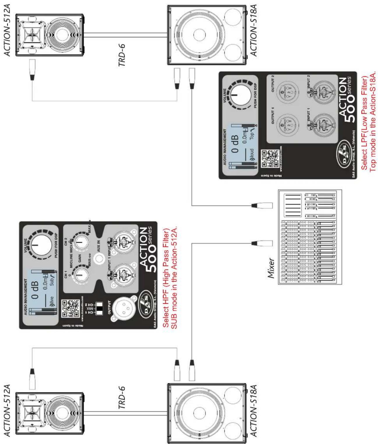
2× ACTION-508A + 1× ACTION-S18A
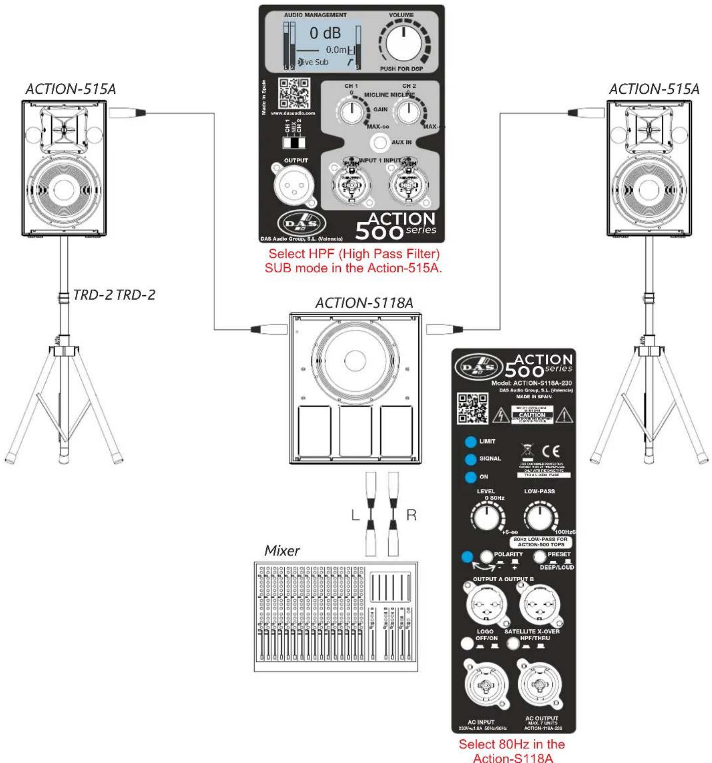
2x ACTION-512A + 2x ACTION-S18A
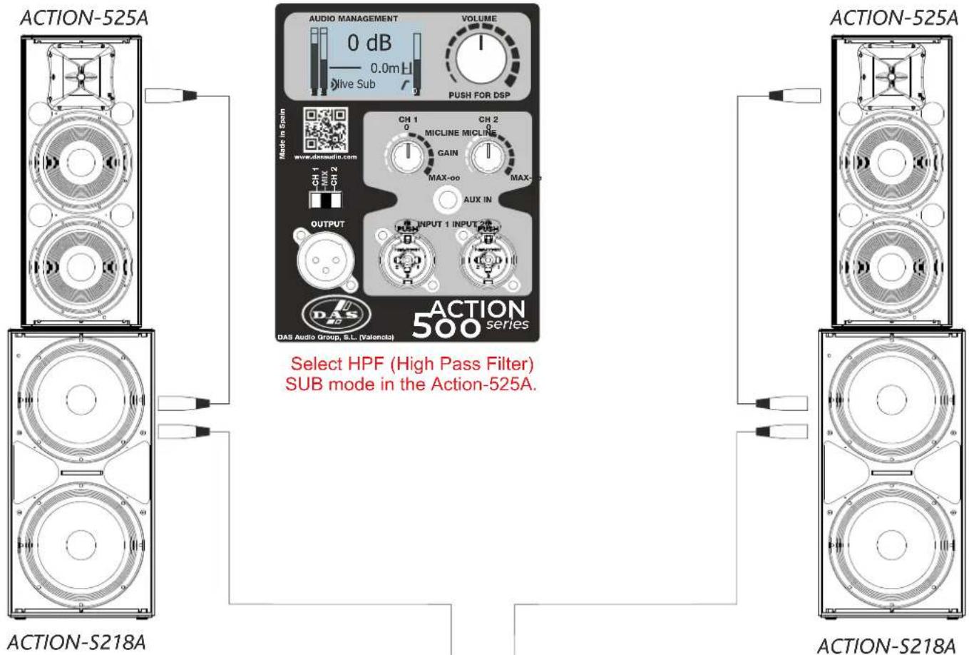
2x ACTION-515A + 1x ACTION-S118A
2x ACTION-525A + 2x ACTION-S218A
LINE DRAWINGS 12 - 13
SPECIFICATIONS 13
AMPLIFIER 14 - 16
Description
ON / OFF
Overload indicators
Equalisation
Overheating
Low mains voltage
Current consumption
Troubleshooting
DISPLAY 17 - 21
Adjusting the levels
Main Menu
System presets
HPF (High Pass Filter)
Delay
Options
RIGGING SYSTEM 22 - 24
ANNEX 25
Line connections: unbalanced and balanced
The exclamation point inside an equilateral triangle is intended to alert the users to the presence of important operating and maintenance (servicing) instructions in the literature accompanying the product. Heed all warnings. Follow all instructions. Keep these instructions.
WARNING: This is a class A product. In a domestic environment this product may cause radio interferences in which case the user may be required to take adequate measures.
Use this product only in E1, E2, E3 or E4 environments according to EN55103-2.
Do not remove mains connector ground, it is dangerous and illegal. Class I device. The product must be connected to a mains socket outlet with protective earth connection. Only use this equipment with an appropriate mains cord for your country.
The lightning and arrowhead symbol warns about the presence of uninsulated dangerous voltage. To reduce the risk of electric shock, do not remove the cover.
Do not install near any heat sources such as radiators, heat registers, stoves or other apparatus that produce heat. The circulation of air through the heatsink must not be blocked.
Do not expose this device to rain or moisture. Do not use this apparatus near water (for example, swimming pools and fountains). Do not place any objects containing liquids, such as bottles or glasses, on the top of the unit. Do not splash liquids on the unit. IP-20 equipment.
This symbol on the product indicates that this product should not be treated as household waste. Instead it shall be handed over to the applicable collection point for the recycling of electrical and electronic equipment.
Working temperature ranges from 15^ C to 45^ C with a relative humidity of 95%, with ±10% of the rated main voltage value indicated on the rear label (according to IEC 60065). If the fuse needs to be replaced, please pay attention to correct type and ratings.
The outer wiring connected to the device requires installation by an instructed person or the use of a flexible cable already prepared.
If the apparatus is connected permanently, the electrical system of the building must incorporate a multipolar switch with a separation of contact of at least 3mm in each pole.
To disconnect the device, you should use the mains plug. Unplug this apparatus during lightning storms, earthquakes or when unused for long periods of time.
Do not place loudspeakers in proximity to devices sensitive to magnetic fields such as television monitors or data storage magnetic material.
For enclosures with tripod socket, the maximum safety height from floor to bottom of enclosure when mounting on a TRD-2 tripod, with legs spread 55cm from the central pole, is:
ACTION-508A ---->125 cm
ACTION-512A ---->115 cm
ACTION-515A ---->105 cm
The appliance should be flown only from the rigging points and by qualified personnel. Do not suspend the box from the handles.
No user serviceable parts inside. Refer all servicing to qualified service personnel. Servicing is required when the apparatus has been damaged in any way, such as power-supply cord or plug is damaged, liquid has been spilled or objects have fallen into the apparatus, the apparatus has been exposed to rain or moisture, does not operate normally or has been dropped.
Clean only with a dry cloth. Do not use any solvent based cleaners.
Reselling of the product is only possible if the user manual is available. Any changes made to the product have to be documented in writing and passed on to the buyer in the event of resale.
GARANTÍA
All our products are warranted against any manufacturing defect for a period of 2 years from date of purchase.
The warranty excludes damage from incorrect use of the product.
All warranty repairs must be exclusively undertaken by the factory or any of its authorised service centers.
To claim a warranty repair, do not open or intend to repair the product.
Return the damaged unit, at shippers risk and freight prepaid, to the nearest service center with a copy of the purchase invoice.

DAS Audio Group, S.L.
Abide by essential objectives relating Directives:
• de Baja Tensión (Low Voltage Directive) 2014/35/UE
• de Compatibilidad Electromagnética (EMC) 2014/30/UE
• RoHS 2011/65/UE
• RAEE (WEEE) 2012/19/UE
In accordance with Harmonized European Norms:
- EN 60065:2014.- Audio, video and similar electronic apparatus. Safety requirements.
- EN 55032:2012.- Electromagnetic compatibility of multimedia equipment. Emission requirements.
- EN 55103-2:2009.- Electromagnetic compatibility. Product family standard for audio, video, audio-visual and entertainment lighting control apparatus for professional use. Part 2:Immunity.
- EN 50581:2012.- Technical documentation for the assessment of electrical and electronic products with respect to the restriction of hazardous substances.
INTRODUCTION
The action 500 series inherits the exceptional sound quality and rugged build that have made DAS professional systems an internacional sound reinforcement standard. Designed from “real-world” experience, they offer users outstanding performance, absolute reliability, and unparalleled convenience. Whether it is in a high-profile venue or on the stage of a major event, the action 500 series will provide the power and definition needed to make your performance a success.
Settings
natural_image
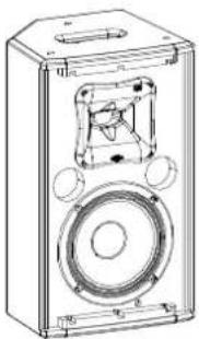
Technical line drawing of a speaker or audio device with no visible text or symbolsACTION-508A
- Compact multi-purpose system with monitor position
- 8" bass loudspeaker, 8GV (1,5" VCD).
- Compressor driver with titanium diaphragm, M-34 (1,4" VCD).
- Reduces size and weight
- Pole mount socket
The ACTION-508A offers a multi-angle enclosure which allows it to be used in stage monitor applications as well as a compact P.A. system. The 720 W peak power of the Class D amplifier provides extended bandwidth, improved dynamic range and exceptionally low distortion-features hard to find on other systems in this market segment. The 8GV loudspeaker provides accurate low frequency reproduction. High frequencies are handled by the M-34 compression driver with 1" exit and titanium diaphragm offering excellent performance.
natural_image
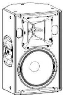
Technical line drawing of a rectangular electronic device with a speaker and circular base (no text or symbols)ACTION-512A
-Two-way powered system.
-12" bass loudspeaker, 12MI4 (2,5" VCD).
-Compressor driver with titanium diaphragm, M-34 (1,4" VCD).
-Asimetric encolusure design for stage monitor use.
-Built-in rigging points (eyebolt based).
-Stand mountable.
The ACTION-512A is a powered loudspeaker (2 channel Class D amplifier), that utilizes a 12" low frequency transducer and a 1" exit compression driver. The multi-angle cabinet is constructed of Birch plywood protected by an environmentally friendly black paint finish. Two bar handles and a steel grille are provided. A 35mm tripod socket with angle double (0° and -10°) allows for stand mounting.
natural_image
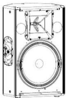
Technical line drawing of a speaker or audio device with a circular head and front panel (no text or symbols)ACTION-515A
-Two-way powered system
-15" bass loudspeaker, 15MI4 (2,5" VCD)
-Compression driver with titanium diaphragm, M-34 (1,4" VCD)
-Asymmetric enclosure design for stage monitor use
-Built-in rigging points (eyebolt bassed)
-Stand mountable
ACTION-515A is a powered loudspeaker (2 channel Class D amplifier), uses a 15" low frequency transducer and a 1" exit compression driver with titanium diaphragm. The cabinet is constructed from Birch plywood and finished with an environmentally friendly black paint finish. Two bar handles are provided and a steel grille protects components. A 35mm tripod socket with angle double (0° and -10°) allows for stand mounting. Rigging points provide a safe and simple solution for suspending the ACTION-515A
natural_image
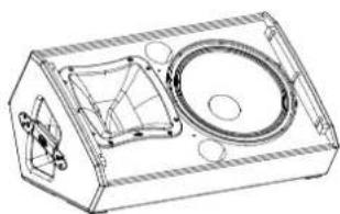
Technical line drawing of a mechanical housing or enclosure with internal components (no text or symbols)ACTION-M512A
-Dedicated powered stage monitor.
-12" bass loudspeaker, 12MI4 (2,5" VCD).
-Compression driver with titanium diaphragm, M-34 (1,4" VCD).
-Low profile enclosure design for minimum visual impact.
-Black paint finish.
-Stand mountable.
The ACTION-M512A is a dedicated powered stage monitor (2channel Class D amplifier). The enclosure ir constructed from Birch plywood and is protected with a black paint finish. Two side located handles facilitate handling and a steel grille protects the components. A pole mount socket adds versatility to the ACTION-M512A.
natural_image
Technical line drawing of a multi-tiered speaker or audio unit with dual speakers and control panel (no text or symbols)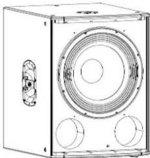
natural_image
Technical line drawing of a rectangular electronic device with three circular ports and a central speaker grille (no text or symbols)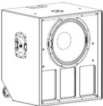
natural_image
Technical line drawing of a mechanical device with a circular vent and side compartments (no text or symbols)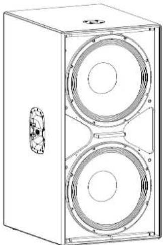
natural_image
Technical line drawing of a two-tiered speaker enclosure with no text or symbolsACTION-525A
- 2-way powered system
- 2 x 15" bass loudspeaker, 15MI (2,5" VCD)
- Compression driver with titanium diaphragm, M-44 (1,75" VCD)
- Two steel-reinforced handles
The ACTION-525A is a powered loudspeaker (2 channel Class D amplifier), that utilizes two 15" bass loudspeakers for extra low frequency punch and higher SPL. High frequencies are handled by a 1" compression driver with titanium diaphragm. The trapezoidal cabinet is constructed using Birch plywood and protected with a hard-wearing black paint finish. Two bar handles and a steel grille sealed against corrosion using a polyamide powder coat finish are provided. Rigging points provide a safe and simple way to fly the ACTION-525A cabinets.
ACTION-S18A
- Bass-reflex powered subwoofer system
- 18" low frequency transducer, 18FW4 (3" VCD)
- Precise and powerful bass reproduction
- Top located pole mount socket
The ACTION-S18A bass powered system (Class D amplifier) incorporates a 18" low frequency transducer with a 3" voice coil mounted as a direct radiator into a bass-reflex cabinet. The loudspeaker is protected by a perforated steel grille, sealed against corrosion using a powder coat finish. The ACTION-S18A is designed for use in biamped systems. A top located pole-mount socket permits mounting full-range systems above the ACTION-S18A and two bar handles makes moving easy.
ACTION-S118A
- Powered horn-bass subwoofer system
- Class D 3200W amplifier
- 1x 18" long excursion woofer, 18LX (4" VCD)
- Deep/Loud EQ selector
- Filtered output defeat switch
- Variable 80-125 Hz high-pass filter
- Gain control and polarity switch
- Top located pole mount socket
The ACTION-S118A horn bass powered system (Class D amplifier) incorporates a 18" long excursion woofer with a 4" voice coil mounted as a direct radiator with load cabinet. The loudspeaker is protected by a perforated steel grille, sealed against corrosion using a powder coat finish. The ACTION-S118A is designed for use in biamped systems. A top located pole-mount socket permits mounting full-range systems above the ACTION-S118A and two bar handles makes moving easy.
ACTION-S218A
- High output bass-reflex powered subwoofer system
- Twin 18" loudspeakers, 18FW4 (3" VCD)
- Durable black paint finish
- Side located bar handles
This bass-reflex powered subwoofer system uses dual 18" bass loudspeakers equipped with 3" voice coils. The exceptional power handling capacity and efficiency provide high sound pressure levels of powerful bass. Two hand locations facilitate handling. The cabinet is designed to be stacked in the vertical position in order to reduce the units "on-stage" footprint.
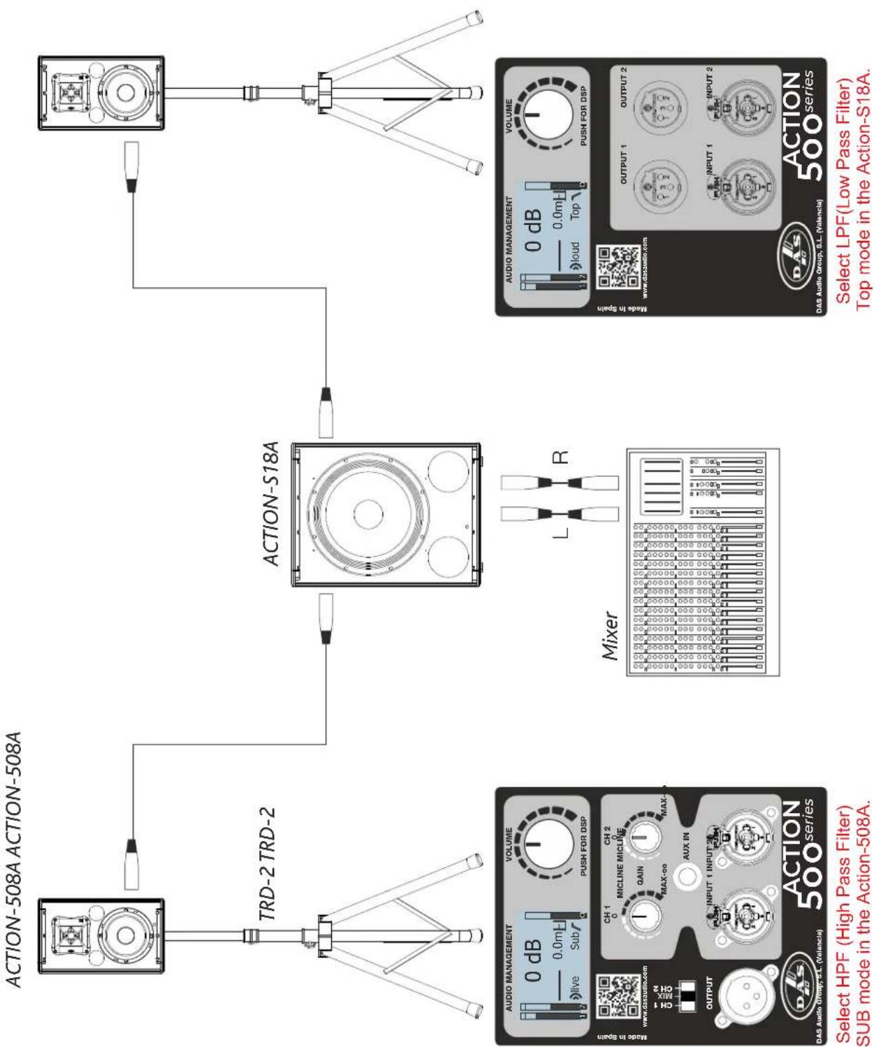
flowchart
graph TD
    A["TRD-2 TRD-2"] --> B["ACTION-S18A"]
    B --> C["Select HPF (High Pass Filter) SUB mode in the Action-508A."]
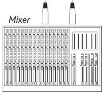
    B --> D["Mixer"]
    D --> E["Select LPF (Low Pass Filter) Top mode in the Action-S18A."]
flowchart
graph TD
    A["TRD-6"] --> B["ACTION-512A"]
    B --> C["MODE in Spain"]
    C --> D["Select HPF (High Pass Filter) SUB mode in the Action-512A."]
    D --> E["Mixer"]
    E --> F["Select LPF (Low Pass Filter) Top mode in the Action-S18A."]
    F --> G["TRD-6"]
    G --> H["MODE in Spain"]
    H --> I["Select HPF (High Pass Filter) SUB mode in the Action-512A."]
    I --> J["MODE in Spain"]
    J --> K["Mixer"]
    K --> L["Select LPF (Low Pass Filter) Top mode in the Action-S18A."]
flowchart
graph TD
    A["TRD-2 TRD-2"] --> B["ACTION-515A"]
    B --> C["MODE in Spain"]
    C --> D["DATA Audio Group, S.L. (Valencia)"]
    D --> E["Select HPF (High Pass Filter) SUB mode in the Action-515A."]
    E --> F["ACTION-S118A"]
    F --> G["Mixer"]
    G --> H["Select 80Hz in the Action-S118A"]
    H --> I["DATA Audio Group, S.L. (Valencia)"]
    I --> J["OUTPUT A OUTPUT B"]
    J --> K["LOGO OFF/ON"]
    K --> L["AC INPUT 230V=1.8A 50Hz/90Hz"]
    L --> M["AC OUTPUT MAX: 80Hz/1MHz"]
    M --> N["LEVEL 0.80Hz"]
    N --> O["LOW-PASS 15-00"]
    O --> P["80Hz LOW-PASS FOR ACTION-500 TOPS"]
    P --> Q["Polarity"]
    Q --> R["Preset DEEP/LOUD"]
    R --> S["CAPTURE CAPTURE"]
    S --> T["CAUTION CAPTURE"]
    T --> U["DAIS 500 series Model: ACTION-S118A-230"]
text_image
ACTION-525A AUDIO MANAGEMENT 0 dB 0.0m Live Sub VOLUME PUSH FOR DSP Mode in Spain www.dasaudio.com CH 1 0 CH 2 MICLINE MICLINE GAIN MAX-oo MAX-0 AUX IN OUTPUT INPUT 1 INPUT 2 DAS DAS Audio Group, S.L. (Valencia) ACTION-500 series ACTION-525A Select HPF (High Pass Filter) SUB mode in the Action-525A. ACTION-S218A ACTION-S218A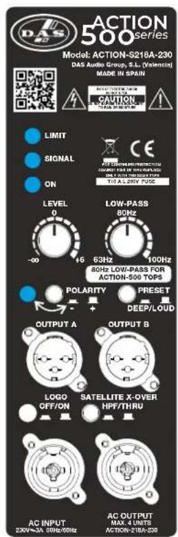
text_image
ACTION 500 series Model: ACTION-S218A-230 DAS Audio Group, S.L. (Valencia) MADE IN SPAIN LIMIT SIGNAL ON LEVEL 0 -00 6 46 63Hz 400Hz 80Hz LOW-PASS FOR ACTION-500 TOPS Polarity + PRESET DEEP/LOUD OUTPUT A OUTPUT B LOGO OFF/ON SATELLITE X-OVER HPF/THRU AC INPUT 230V~3A 30Hz/6Hz AC OUTPUT MAX. 4 UNITS ACTION-218A-230Select 80Hz mode in the Action-S218A
text_image
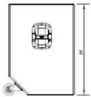
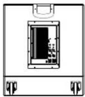
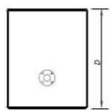
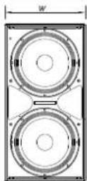
MixerALL DIMENSIONS IN MILLIMETERS
text_image
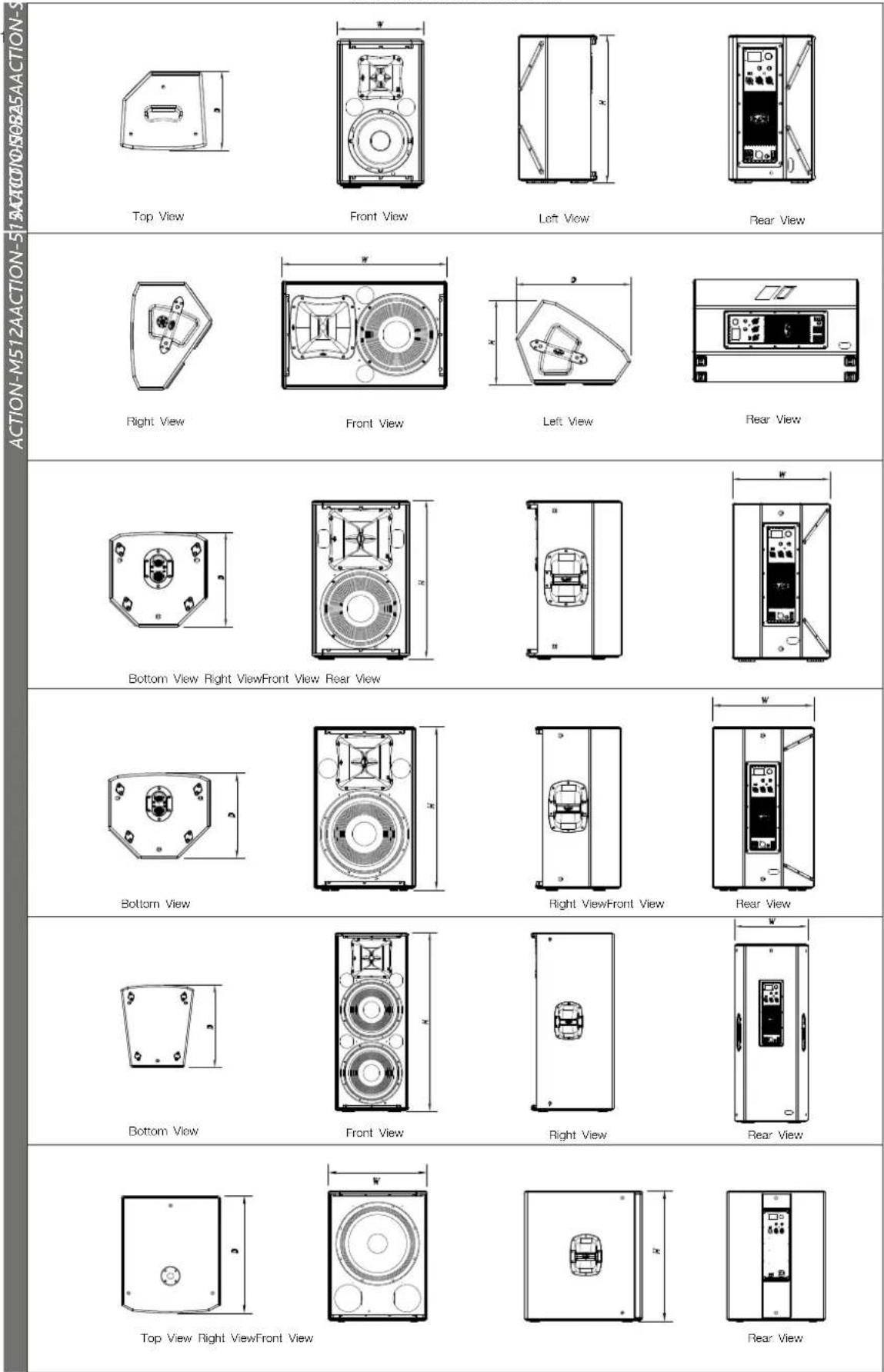
ACTION-M512ACTION-512ACTION-512ACTION-512ACTION-512ACTION-512ACTION-512ACTION-512ACTION-512ACTION-512ACTION-512ACTION-512ACTION-512ACTION-512ACTION-512ACTION-512ACTION-512ACTION-512B0704088888888888888888888888888888888888888888888888888888888888888888888888888888888888888 Top View Front View Left View Rear View Right View Front View Left View Rear View Bottom View Right View Front View Rear View Bottom View Right View Front View Rear View Bottom View Front View Right View Rear View Top View Right View Front View Rear ViewALL DIMENSIONS IN MILLIMETRES
Top View
natural_image
Technical diagram of a circular component with three rectangular sections and dimension label 'W' (no text or symbols beyond the label)Front View
Left View
Rear View
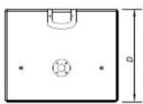
Top View
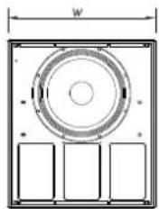
Front View
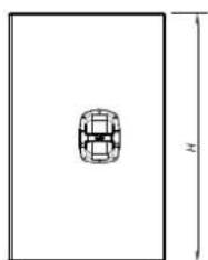
natural_image
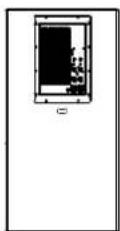
Simple line drawing of a rectangular box with a small circular object on the top and a dimension label 'N' on the side (no text or symbols on the object itself)Left View
Rear View
SPECIFICATIONS
| Model | ACTION-508A | ACTION-MS12A | ACTION-512A | ACTION-515A |
| Power Amplifier | 720 W peak360 W continuous(Class D Bi-amplified)Balanced Differential LineLine: 20 kOhmsMic: 20 kOhmsLine: 1.95V (+8dBu)Mic: 20mV (-32dBu)65 Hz - 20 kHz90° x 60° (Rotatable)122 dBLF: 1 x 80V / 80VHF: 1 x M-34 / GM-M34Birch PlywoodBlack PaintINPUT: Female XLR-JackAUX INPUT: 3.5mm Mini JackLOOP THRU: Male XLRAC INPUT: PowerCon | 1000 W peak500 W continuous(Class D Bi-amplified)Balanced Differential LineLine: 20 kOhmsMic: 20 kOhmsLine: 1.95V (+8dBu)Mic: 20mV (-32dBu)60 Hz - 20 kHz80° x 50° (Rotatable)130 dBLF: 12M14 / GM-12M14HF: M-34 / GM-M34Birch PlywoodBlack PaintINPUT: Female XLRAUX INPUT: 3.5mm Mini JackLOOP THRU: Male XLRAC INPUT: PowerConAC OUTPUT: PowerCon | 1000 W peak500 W continuous(Class D Bi-amplified)Balanced Differential LineLine: 20 kOhmsMic: 20 kOhmsLine: 1.95V (+8dBu)Mic: 20 mV (-32dBu)50 Hz - 20 kHz90° x 60° (Rotatable)131 dBLF: 12M14 / GM-12M14HF: M-34 / GM-M34Birch PlywoodBlack PaintINPUT: Female XLRAUX INPUT: 3.5mm Mini JackLOOP THRU: Male XLRAC INPUT: PowerCon | 1000 W peak500 W continuous(Class D Bi-amplified)Balanced Differential LineLine: 20 kOhmsMic: 20 kOhmsLine: 1.95V (+8dBu)Mic: 20mV (-32dBu)45 Hz - 20 kHz90° x 60° (Rotatable)131 dBLF: 15M14 / GM-15M14HF: M-34 / GM-M34Birch PlywoodBlack PaintINPUT: Female XLRAUX INPUT: 3.5mm Mini JackLOOP THRU: Male XLRAC INPUT: PowerCon |
| Frequency Range (-10 dB)HF Horn Coverage Angles (-6 dB)Maximum Peak SPL at 1mTransducers/ Replacement PartsEnclosure MaterialColor/FinishConnectors | 115V, 1.6A, 50 Hz / 60 Hz230 V, 0.8A, 50 Hz / 60 Hz47.5 x 28.0 x 25.5 cm18.7 x 11 x 10 in9.9 kg (21.8 lb)AXU-ACT8TRD-2TRD-6TRD-7 | |||
| AC Power RequirementsDimensions (H x W x D)WeightAccessories | 115V, 1.6A, 50 Hz / 60 Hz230 V, 0.8A, 50 Hz / 60 Hz47.5 x 28.0 x 25.5 cm18.7 x 11 x 10 in9.9 kg (21.8 lb)AXU-ACT8TRD-2TRD-6TRD-7 | 115V, 2.2A, 50 Hz / 60 Hz230V, 1.1A, 50 Hz / 60 Hz42 x 64.5 x 31.8 cm16.5 x 25.4 x 12.5 in19 kg (41.8 lb)TRD-2TRD-6TRD-7 | 115V, 2.2A, 50 Hz / 60 Hz230V, 1.1A, 50 Hz / 60 Hz61.8 x 38.0 x 37.8 cm24.3 x 15.0 x 14.9 in21 kg (48.2 lb)ANL-2AXU-ACT12TRD-2TRD-6TRD-7 | 115V, 2.2A, 50 Hz / 60 Hz230V, 1.1A, 50 Hz / 60 Hz71.8 x 44.4 x 37.5 cm28.3 x 17.5 x 14.8 in24 kg (52.8 lb)ANL-2TRD-2TRD-6TRD-7 |
| Model | ACTION-525A | ACTION-518A | ACTION-5118A | ACTION-218A |
| Power Amplifier | 1000 W peak500 W continuous(Class D Bi-amplified)Balanced Differential LineLine: 20 kOhmsMic: 20 kOhmsLine: 1.95V (+8dBu)Mic: 20mV (-32dBu)45 Hz - 20 kHz | 1500 W peak750 W continuous(Class D)Balanced Differential LineLine: 20 kOhmsLine: 1.95V (+8dBu)35 Hz - 125 Hz(variable LPF)134 dBLF: 18FW4 / GM-18FW4 | 3200 W peak1600 W continuous(Class D)Balanced Differential LineLine: 20 kOhmsLine: 1.95V (+8dBu)35 Hz - 125 Hz(variable LPF)137 dBLF: 1x 18LX / GM-18LX | 3200 W peak1600 W continuous(Class D)Balanced Differential LineLine: 20 kOhmsLine: 1.95V (+8dBu)35 Hz - 125 Hz(variable LPF)140 dBLF: 2x 18FW4 / GM-18FW4 |
| Input TypeInput ImpedanceSensitivity | 90° x 60° (Rotatable)134 dBLF: 2x 15MI / GM-15MIHF: M-44 / GM-M44Birch PlywoodBlack PaintINPUT: Female XLRAUX INPUT: 3.5mm Mini JackLOOP THRU: Male XLRAC INPUT: PowerCon | |||
| Frequency Range (-10 dB)HF Horn Coverage Angles (-6 dB)Maximum Peak SPL at 1mTransducers/ Replacement PartsEnclosure MaterialColor/FinishConnectors | 90° x 60° (Rotatable)134 dBLF: 2x 15MI / GM-15MIHF: M-44 / GM-M44Birch PlywoodBlack PaintINPUT: Female XLRAUX INPUT: 3.5mm Mini JackLOOP THRU: Male XLRAC INPUT: PowerCon | |||
| AC Power RequirementsDimensions (H x W x D)WeightAccessories | 115V, 2.2A, 50 Hz / 60 Hz230V, 1.1A, 50 Hz / 60 Hz108.7 x 50.2 x 50.2 cm42.8 x 19.8 x 19.8 in41 kg (50.2 lb)ANL-2 | 115V, 2.8A, 50 Hz / 60 Hz230V, 1.4A, 50 Hz / 60 Hz71.8 x 54.0 x 67.0 cm28.3 x 21.3 x 26.4 in40.5 kg (89.1 lb)TRD-6TRD-7 | 115V, 3.6A, 50 Hz / 60 Hz230V, 1.8A, 50 Hz / 60 Hz79.1 x 69.0 x 56.6 cm31.1 x 27.2 x 22.3 in55 kg (121 lb)TRD-6TRD-7 | 115V, 6A, 50 Hz / 60 Hz230V, 3A, 50 Hz / 60 Hz108.7 x 54.0 x 67.0 cm42.0 x 21.3 x 26.4 in63 kg (138.5 lb)TRD-6TRD-7 |
DAS Audio Group, S.L., continuously strives to enhance its products through investigation and development. All specifications are subject to change without prior notice.
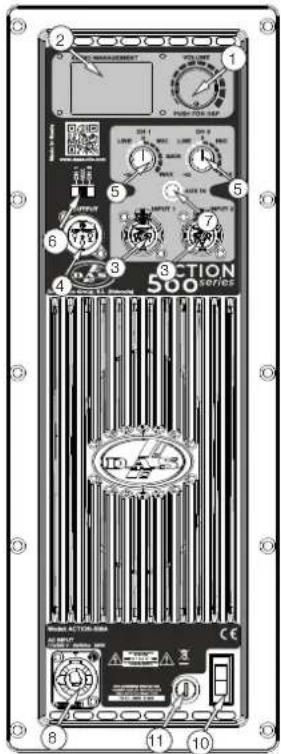
text_image
2 1 3 5 6 7 8 9 10 SECTION 500 SERIESAmplifier :
ACTION-508A
ACTION-512A
ACTION-515A
ACTION-525A
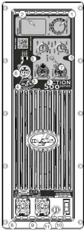
text_image
1 2 3 4 5 6 7 8 9 10 SECTION 500 SERIESAmplifier :
ACTION-M512A
Description
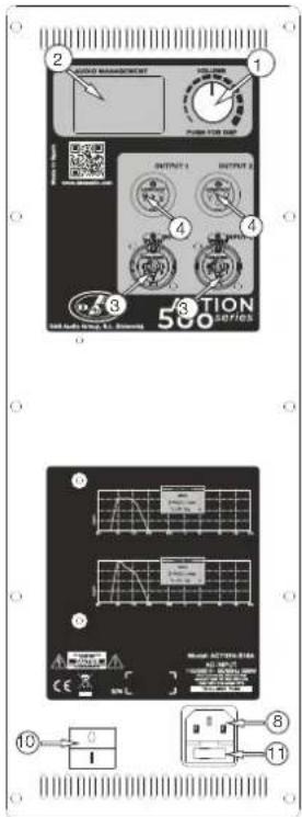
1) MASTER VOLUMEN AND DSP CONTROL:
Use the encoder to select the desired output volume and push/hold it to access to the different DSP and cabinet settings.
2) MAIN SCREEN:
In the main screen all selected parameters and settings are shown. Besides this, there are two input level indicators on the left, one output level indicator on the right and the center area is reserved to display messages as Input Clip or Limit.
3) INPUT CONNECTORS:
1/4" Jack+XLR combined socket-type input signal connectors. This is a balanced connector just like the LOOP THRU connector with the following pin assignments:
or S = GND (ground).
2 or T = (+) Non inverted input.
3 or R =(-) Inverted input.
4) OUTPUT CONNECTORS:
XLR-type output signal connector for connecting several units together and sending them all the same signal. Except in ACTION-S18A, the user can select the output signal with a switch.
5) INPUT GAIN CONTROL:
For channels 1, 2 and AUX IN, gain control, line and microphone.
text_image
2 3 4 5 6 7 8 9 10 11 OUTPUT 1 OUTPUT 2 OUTPUT 3 OUTPUT 4 OUTPUT 5 500 500 Cable Audio Group, L. S. Instruments Cable Audio Group, L. S. Instruments Cable Audio Group, L. S. Instruments Cable Audio Group, L. S. Instruments Cable Audio Group, L. S. Instruments Cable Audio Group, L. S. Instruments Cable Audio Group, L. S. Instruments Cable Audio Group, L. S. Instruments Cable Audio Group, L. S. Instruments Cable Audio Group, L. S. InstrumentsAmplifier :
ACTION-S18A
It allows the user to select which input channel signal to be sent to other cabinets. In ACTION-508A, ACTION-M512A, ACTION-512A, ACTION-515A and ACTION-525A: User can select Ch1, Ch2 or both (Mix). In ACTION-S118A and ACTION-S218A: User can select the same input signal or filtered signal (HPF) with a cut-off frequency of 100 Hz.
7) AUX IN:
3.5 mm audio jack input for connecting external audio media devices, such as MP3 players. The input source is controlled with Gain control 1.
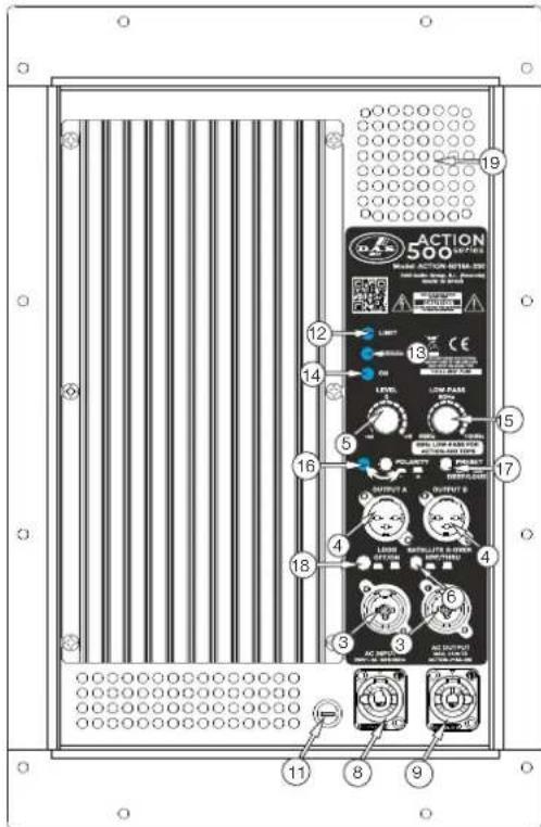
8) AC INPUT :
Standard IEC-60320 (only ACTION-S18A) or PowerCon NAC3FCA mains connector (inserted, rotated and locked for ON). Only use this equipment with an appropriate mains cord.
9) AC OUTPUT (only ACTION-M512A, ACTION-S118A and ACTION-S218A):
PowerCon NAC3FCB connector for AC loop thru to other units (see unit's label). Only
use this equipment with an appropriate mains cord.
10) POWER :
Mains power ON/OFF switch.
11) FUSE :
Fuse holder. Only use the recommended fuse type and size.
12) LIMIT (only ACTION-S118A and ACTION-S218A):
Red LED indicates amplifier saturation. Amplifier limiter indicator lights.
13) SIGNAL (only ACTION-S118A and ACTION-S218A):
Green LED indicates signal presence.
14) ON (only ACTION-S118A and ACTION-S218A):
Green LED indicates that the unit is ON.
15) LOW-PASS CROSSOVER (only ACTION-S118A and ACTION-S218A):
Button for adjusting the upper cut-off frequency for the subwoofer unit (see label). We recommend a cut-off frequency of 80 Hz.
16) POLARITY (only ACTION-S118A and ACTION-S218A):
Switch for inverting the phase of the unit. The LED indicates the inverted phase.
17) PRESET DEEP/LOUD (only ACTION-S118A and ACTION-S218A):
Button for switching between two types of frequency response, DEEP or LOUD.
18) LOGO OFF/ON (only ACTION-S118A and ACTION-S218A):
Press the button to illuminate the logo.
19) Fan (only ACTION-S118A and ACTION-S218A).
text_image
ACTION 500 MINI-ACTION-INTER-390 MINI-ACTION-INTER-390 MINI-ACTION-INTER-390 MINI-ACTION-INTER-390 MINI-ACTION-INTER-390 MINI-ACTION-INTER-390 MINI-ACTION-INTER-390 MINI-ACTION-INTER-390 MINI-ACTION-INTER-390 MINI-ACTION-INTER-39 MINI-ACTION-INTER-39 MINI-ACTION-INTER-39 MINI-ACTION-INTER-39 MINI-ACTION-INTER-39 MINI-ACTION-INTER-39 MINI-ACTION-INTER-39 MINI-ACTION-INTER-39 MINI-ACTION-INTER-39 MINI-ACTION-INTER-39 MINI-ACTION-INTER-38 MINI-ACTION-INTER-38 MINI-ACTION-INTER-38 MINI-ACTION-INTER-38 MINI-ACTION-INTER-38 MINI-ACTION-INTER-38 MINI-ACTION-INTER-38 MINI-ACTION-INTER-38 MINI-ACTION-INTER-38 MINI-ACTION-INTER-37 MINI-ACTION-INTER-37 MINI-ACTION-INTER-37 MINI-ACTION-INTER-37 MINI-ACTION-INTER-37 MINI-ACTION-INTER-37 MINI-ACTION-INTER-36 MINI-ACTION-INTER-36 MINI-ACTION-INTER-36 MINI-ACTION-INTER-36 MINI-ACTION-INTER-36 MINI-ACTION-INTER-35 MINI-ACTION-INTER-35 MINI-ACTION-INTER-35 MINI-ACTION-INTER-35 MINI-ACTION-INTER-34 MINI-ACTION-INTER-34 MINI-ACTION-INTER-34 MINI-ACTION-INTER-34 MINI-ACTION-INTER-33 MINI-ACTION-INTER-33 MINI-ACTION-INTER-33 MINI-ACTION-INTER-32 MINI-ACTION-INTER-32 MINI-ACTION-INTER-32 MINI-ACTION-INTER-31 MINI-ACTION-INTER-31 MINI-ACTION-INTER-31 MINI-ACTION-INTER-30 MINI-ACTION-INTER-29 MINI-ACTION-INTER-29 MINI-ACTION-INTER-28 MINI-ACTION-INTER-28 MINI-ACTION-INTER-27 MINI-ACTION-INTER-27 MINI-ACTION-INTER-26 MINI-ACTION-INTER-26 MINI-ACTION-INTER-25 MINI-ACTION-INTER-25 MINI-ACTION-INTER-24 MINI-ACTION-INTER-24 MINI-ACTION-INTER-23 MINI-ACTION-INTER-22 MINI-ACTION-INTER-21 MINI-ACTION-INTER-20 MINI-ACTION-INTER-19 MINI-ACTION-INTER-18 MINI-ACTION-INTER-17 MINI-ACTION-INTER-16 MINI-ACTION-INTER-15 MINI-ACTION-INTER-14 MINI-ACTION-INTER-13 MINI-ACTION-INTER-12 MINI-ACTION-INTER-11 MINI-ACTION-INTER-10 MINI-ACTION-INTER - 9.0000000000000000000000000000000000000000000000000000000000000000000000000000000000000000000000000000Amplifier : ACTION-S118A ACTION-S218A
ON/OFF
A sound system should be switched on sequentially. Switch on the self-powered units last in your sound system (switch on the subwoofer before the mid-high system). Switch on the sound sources such as CD players or turntables, then the mixer, then the processors, and finally the self-powered unit. If you have several units, it is recommended that you switch them on sequentially one at a time.
Follow the inverse order when switching off, turning self-powered units off before any other element in the sound system.
Disconnect the device by removing the mains connector from the mains socket. The mains connector and mains socket must always be freely accessible and never covered or blocked in any way. The mains cable can be detached from the device by disconnecting the standard IEC-60320 connector (only ACTION-S18A). Always disconnect the device by removing the mains connector from the mains socket before detaching the mains cable at the standard IEC-60320 connector (only ACTION-S18A).
The rest of models use a power cable equipped with a Neutrik PowerCon NC3FCA connector. Power can be daisy chained via the NC3FCB output connector (see details on product label).
IMPORTANT: Do not disconnect the unit while in use.
Ensure that the device is disconnected from the mains by observing that the ON LED is turned off. Please note that the ON LED can stay on for several seconds after the mains power has been disconnected.
Overload indicator
This device has an indicator (LIMIT LED) that lights when the signal is excessive.
The indicator should not be lit continuously. This distorts the signal (quickly fatiguing your ears) and may damage the speakers. Therefore, it is recommended that you never work with this LED on; at most it should blink only occasionally.
Equalisation
The unit does not need extreme settings of equalisation to produce quality sound. Avoid high levels of gain on the equalisers. Gain values above +3 dB on a console's EQ are not recommended.
Overheating
This equipment does not normally overheat during normal conditions of use. When overheating occurs, the unit protects itself. You should then find out why and if necessary contact an authorised dealer for technical assistance.
Normally it is enough just to let the unit cool down after you have corrected the problem so that the system functions properly again.
ACTION-S118A and ACTION-S218A amplifiers are equipped with fan and heatsink to maintain the correct operating temperature.
Keep grilles clean and dust-free.
Do not block or obstruct in any way the air entrance or exit while the equipment is in use.
Air circulates from the bottom to the top of the amplifier.
Low mains voltage
If mains voltage falls below the shutdown voltage for the unit, it will stop playing. When acceptable levels are regained, the unit will switch back on automatically.
Therefore the current consumed by a 115V version is double the 230V version to achieve the same acoustic power level.
| Pink NoiseMains 230 Vrms | 1/3 Power |
| ACTION-508A | 0.8A |
| ACTION-512A | 1.1A |
| ACTION-M512A | 1.1A |
| ACTION-515A | 1.1A |
| ACTION-525A | 1.1A |
| ACTION-S18A | 1.4A |
| ACTION-S118A | 1.8A |
| ACTION-S218A | 3A |
Troubleshooting
| PROBLEM | CAUSE | SOLUTION |
| No sound from the unit. The SIGNAL LED does not light up. | 1 - The signal source is sending no signal.2 - Defective cable.3 - The amplifier has overheated. | 1 - Check that the mixer or sound source is sending signal to the UNIT.2 - Check that the cable from the sound source to the UNIT is connected correctly. Replace the cable if defective.3 - Allow the unit to cool down for some minutes and it will function again. Check the main output level of the mixer or channel gains since the unit will have been functioning with excessive levels. |
| Full power cannot be obtained. The LIMIT LED never lights up. | The signal source does not have a hot enough output. | If using a mixer, use the balanced ou tpu t i f a va il ab le . U se professional mixer with a hotter output. |
| Sound is distorted. The LIMIT LED is not on, or only lights up occasionally. | The mixer or signal source is distorting. | Turn mixer channel gains down. Check that none of your signal sources are distorting. |
| Sound is distorted and very low and LIMIT LED lights up. | The system is overloaded and has reached maximum power. | Turn down the mixer's output. |
| Hum or buzz when a mixer is connected to the unit. | 1.- The console probably has un- balanced outputs. You may be using an incorrect un-balanced to balanced cable.2.- The mixer and the powered speaker are not plugged into the same mains outlet.3.- The audio signal cable is too long or too close to an AC cable | 1.- Read the appendix of this manual to make a correct un- balanced to balanced cable.2.- Connect the mixer and the unit to the same mains outlet.3.- Use a cable that is as short as possible and/or move the audio signal cable away from mains cables. |
| Hum or buzz when using lightir controls in the same building. | 1.- The audio signal cable is too long or too close to the lighting cable.2.- On a sound system with three- phase AC, the lighting equipment and the UNIT are connected to the same phase. | 1.- Move the audio signal cable away from lighting cables. Try to find out at what point the noise is leaking into the system.2.- Connect the sound system to a different phase than the lights. You may need the help of an electrician. |
| The ON LED does not light up when the mains connector is connected and the unit is switched to ON. | 1.- Bad or loose AC connection to the UNIT or the mains outlet.2 - Faulty AC cable.3 - Blown Fuse.4 - The mains voltage is out range. | 1.- Check your connections.2.- Check the cables, connectors and AC power with a suitable mains tester.3.- Replace the blown fuse for another of the same type and size.4.- If the multimeter determines that the mains voltage is out the range, you may need the assistance of an electrician to find an appropriate solution. |
DISPLAY (except ACTION-S18A, ACTION-S118A & ACTION-S218A)
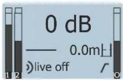
By default the state of the screen is the following:
text_image
0 dB —— 0.0mH live off /Once the input source (s) have been connected to the amplifier's cabinet, the user has to adjust the levels.
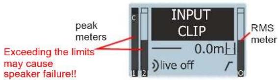
For the two input channels (1 and 2), two independent gain controls are available. Be careful when setting the input volume and do not exceed the maximum level shown on the meters: (input clip shown on channel one)
text_image
INPUT CLIP peak meters 0.0m RMS meter Exceeding the limits may cause speaker failure!! live offAfter having set the input volume values under the maximum level, user has to adjust output volume with the master control. The level is shown in the right meter of the screen. As with the inputs be careful not exceeding the limit: (LIMIT shown)
Notes:
The only models in this series that do not have a display are: ACTION-S118A and ACTION-S218A.
In the model ACTION-M512A the preset activated by default is "Monitor" while in the other models it is "Live". While your preset is "Monitor" the display will turn off completely during use.
If in the "LOGO" menu we have chosen the "Limit" option, the anagram will flash when the limiter is activated. If we have chosen "On" it will remain lit, while if the option chosen is "Off" it will remain off.
PRESETS:
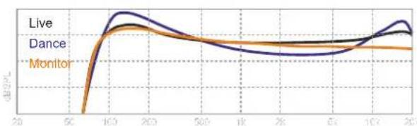
Three factory settings (live, dance, monitor) depending on the type of music/use that has been configured inside the unit:
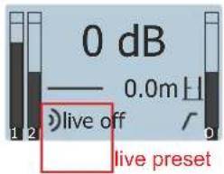
text_image
0 dB —— 0.0m H live off live presetWith the encoder go to Preset Sub-menu and press the knob to access to the different options:
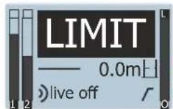
Exceeding the limits may cause speaker failure!!
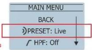
text_image
MAIN MENU BACK PRESET: Live HPF: Off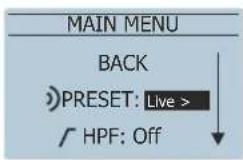
After these two volume adjustments the screen will show something like this (when having the input sources ON):
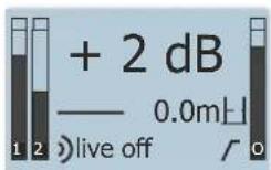
It is highly recommendable working with output volume below 0dB. If maximum level is required user should increase the output level (higher than 0dB)
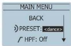
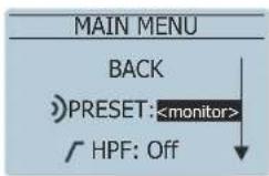
MAIN MENU:
As stated previously by pushing the encoder the user can access to the following options in the MENU:

Differences between Presets
line
| Time | Live | Dance | Monitor | |------|------|-------|---------| | 20 | - | - | - | | 50 | - | - | - | | 100 | 1.0 | 0.9 | 0.8 | | 200 | 0.8 | 0.7 | 0.6 | | 500 | 0.6 | 0.5 | 0.4 | | 1K | 0.5 | 0.4 | 0.3 | | 2K | 0.4 | 0.3 | 0.2 | | 5K | 0.3 | 0.2 | 0.1 | | 10K | 0.2 | 0.1 | 0.05 | | 20K | 0.1 | 0.05 | 0.02 |Note: to enter and select and option always push the encoder. For going back in the menu, the user has to select Back on the screen and press the encoder or just pushing the encoder.
After 30 seconds without using the unit it will go back to the main screen automatically.
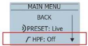
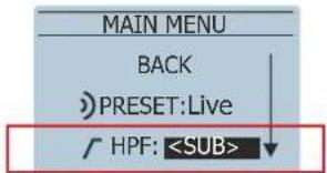
HPF (High Pass Filter):
Two options are available for the cabinets. Go to the HPF Sub-menu and press the encoder. Options appear:
text_image
MAIN MENU BACK PRESET: Live HPF: Off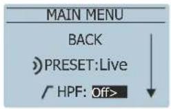
text_image
MAIN MENU BACK PRESET:Live HPF:when combining with subwoofer: ACTION-S18A, ACTION-S118A or ACTION-S218A
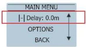
DELAY:
The user can set up a delay in the cabinets by using the delay Sub-menu; from 0 to 9.9m in 0.1m steps. Delay units can be selected between meters or feet:
text_image
MAIN MENU | - | Delay: 0.0m OPTIONS BACK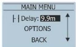
OPTIONS:
In this sub-menu the user can configure all the non-audio related options. Remember that in order to access each parameter it is necessary to push the encoder:
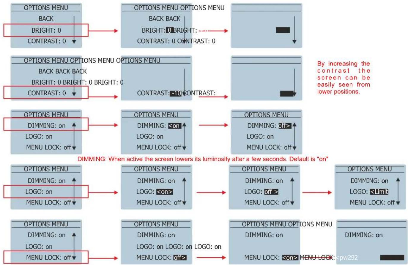
flowchart
graph TD
    A["OPTIONS MENU"] --> B["BACK"]
    B --> C["BRIGHT: 0"]
    C --> D["CONTRAST: 0"]
    D --> E["OPTIONS MENU OPTIONS MENU"]
    E --> F["BACK BACK"]
    F --> G["BRIGHT: 0 BRIGHT: 0"]
    G --> H["CONTRAST: 0 CONTRAST: 0"]
    H --> I["By increasing the contrast the screen can be easily seen from lower positions."]
    J["OPTIONS MENU OPTIONS MENU OPTIONS MENU"] --> K["BACK BACK BACK"]
    K --> L["BRIGHT: 0 BRIGHT: 0 BRIGHT: 0"]
    L --> M["CONTRAST: -10 CONTRAST:"]
    M --> N["OPTIONS MENU"]
    N --> O["DIMMING: on"]
    O --> P["LOGO: on"]
    P --> Q["MENU LOCK: off"]
    Q --> R["OPTIONS MENU DIMMING: <on"]
    R --> S["LOGO: on"]
    S --> T["MENU LOCK: off"]
    T --> U["OPTIONS MENU DIMMING: off>"]
    U --> V["LOGO: on"]
    V --> W["MENU LOCK: off"]
    W --> X["OPTIONS MENU DIMMING: on"]
    X --> Y["LOGO: <Limit"]
    Y --> Z["MENU LOCK: off"]
    Z --> AA["OPTIONS MENU DIMMING: on"]
    AA --> AB["LOGO: <pw292"]
    AB --> AC["MENU LOCK: <on>"]
    AC --> AD["OPTIONS MENU OPTIONS MENU"]
    AD --> AE["DIMMING: on"]
A. User can LOCK the Display and Master Volume Control by enabling this option MENU LOCK: ON
B. User can LOCK the Display and Master Volume Control WITH PASSWORD by enabling this option MENU LOCK: pw292
In case A to unlock just press the encoder:
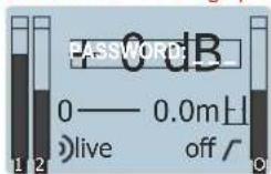
In case B to unlock PUSH encoder and enter the 3 digit password (292):
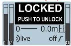
text_image
LOCKED PUSH TO UNLOCK 0—— 0.0m上 live off /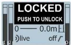

flowchart
graph LR
    A["OPTIONS MENU"] --> B["DLY UNITS: m"]
    A --> C["RESET DEVICE"]
    B <--> D["OPTIONS MENU OPTIONS MENU"]
    D --> E["DLY UNITS: m"]
    D --> F["RESET DEVICE RESET DEVICE"]
    E <--> G["STAND-BY: off"]
    F <--> H["STAND-BY: off>"]
    G <--> I["STAND-BY: <5min>"]
STAND-BY: When no signal is detected the amplifier shuts down. Time can be selected

flowchart
graph LR
    A["OPTIONS MENU OPTIONS MENU OPTIONS MENU"] --> B["STAND-BY: off STAND-BY: off STAND-BY: off"]
    B --> C["DLY UNITS: m"]
    C --> D["RESET DEVICE RESET DEVICE RESET DEVICE"]
    D --> E["DLY UNITS: m>"]
    E --> F["DLY UNITS: <ft"]

text_image
OPTIONS MENU RESET DEVICE RESET DEVICE Are you sure? INFORMATION NO YES BACK This option resets the device to the following values: Preset: live HPF: off Delay: 0m Stand-By: off Dimming: OnDISPLAY (only ACTION-S18A)
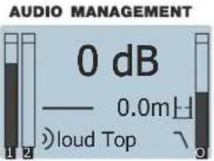
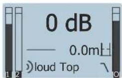
By default the state of the screen is the following:
text_image
AUDIO MANAGEMENT 0 dB —— 0.0mH ● loud Top ▼Once the input source has been connected to the amplifier's cabinet, the user has to check the gain structure of the system.
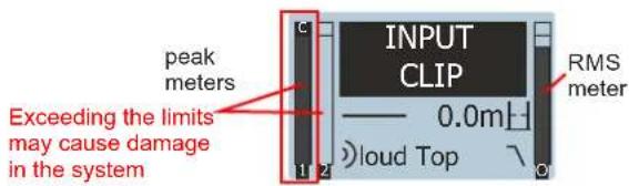
Adjust level output from your processor and/or mixing console in order to prevent INPUT CLIP (left signal meter):
text_image
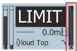
peak meters INPUT CLIP 0.0mH loud Top RMS meter Exceeding the limits may cause damage in the systemAfter having set the input volume values under the maximum level, user has to adjust output volume with the master control. The level is shown in the right meter of the screen. As with the inputs be careful not exceeding the limit: (LIMIT shown)
text_image
LIMIT —— 0.0ml ● loud TopExceeding the limits may cause damage in the system
After these two volume adjustments the screen will show something like this (when having the input sources ON):
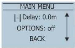
MAIN MENU:
As stated previously by pushing the encoder the user can access to the following options in the MENU:

By scrolling down the encoder more options appear:
PRESETS:
Two factory settings (loud and deep) depending on the type of music/use has been configured by default:
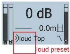
text_image
0 dB —— 0.0mH loud Top loud presetWith the encoder go to Preset Sub-menu and press the knob to access the different options:
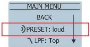
text_image
MAIN MENU BACK PRESET: loud LPF: Top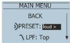
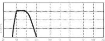
line
| X-Axis | Y-Axis | |---|---| | 20 | 0 | | 70 | 100 | | 100 | 95 | | 200 | 0 | | 300 | 0 | | 400 | 0 | | 500 | 0 | | 600 | 0 | | 700 | 0 | | 800 | 0 | | 900 | 0 | | 1000 | 0 | | 1100 | 0 | | 1200 | 0 | | 1300 | 0 | | 1400 | 0 | | 1500 | 0 | | 1600 | 0 | | 1700 | 0 | | 1800 | 0 | | 1900 | 0 | | 2000 | 0 | | 2100 | 0 | | 2200 | 0 | | 2300 | 0 | | 2400 | 0 | | 2500 | 0 | | 2600 | 0 | | 2700 | 0 | | 2800 | 0 | | 2900 | 0 | | 3000 | 0 | | 3100 | 0 | | 3200 | 0 | | 3300 | 0 | | 3400 | 0 | | 3500 | 0 | | 3600 | 0 | | 3700 | 0 | | 3800 | 0 | | 3900 | 0 | | 4000 | 0 | | 4100 | 0 | | 4200 | 0 | | 4300 | 0 | | 4400 | 0 | | 4500 | 0 | | 4600 | 0 | | 4700 | 0 | | 4800 | 0 | | 4900 | 0 | | 5000 | 1 | | 5100 | 2 | | 5200 | 3 | | 5300 | 4 | | 5400 | 5 | | 5500 | 6 | | 5600 | 7 | | 5700 | 8 | | 5800 | 9 | | 5900 | 10 | | 6000 | 11 | | 6100 | 12 | | 6200 | 13 | | 6300 | 14 | | 6400 | 15 | | 6500 | 16 | | 6600 | 17 | | 6700 | 18 | | 6800 | 19 | | 6900 | 20 | | 7000 | 21 | | 7100 | 22 | | 7200 | 23 | | 7300 | 24 | | 7400 | 25 | | 7500 | 26 | | 7600 | 27 | | 7700 | 28 | | 7800 | 29 | | 7900 | 30 | | 8000 | 31 | | 8100 | 32 | | 8200 | 33 | | 8300 | 34 | | 8400 | 35 | | 8500 | 36 | | 8600 | 37 | | 8700 | 38 | | 8800 | 39 | | 8900 | 41 | | 9123 | -11 (approx) | | ... (approx) | ... (approx) | The chart is a line graph with a legend. The x-axis represents the index of the variable 'X' and the y-axis represents the corresponding 'Y' value. There is no label for the data series. The chart is labeled 'Y'.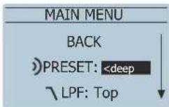
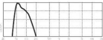
line
| X-Axis | Y-Axis | |---|---| | 20 | 0 | | 40 | 1 | | 60 | 2 | | 80 | 1.5 | | 100 | 1 | | 120 | 0.5 | | 140 | 0 | | 160 | 0 | | 180 | 0 | | 200 | 0 | The chart displays a single data series with no explicit title or axis labels. The values are estimated based on the y-axis label 'Y'.LPF (Low Pass Filter):
There are 3 different options:
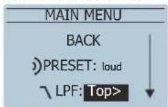
Combination with ACTION-508A, ACTION-M512A, ACTION-512A, ACTION-515A and ACTION-525A
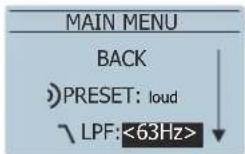
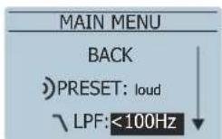
Note: to enter and select and option always push the encoder. For going back in the menu, the user has to select Back on the screen and press the encoder or just pushing the encoder.
After 30 seconds without using the unit it will go back to the main screen automatically.
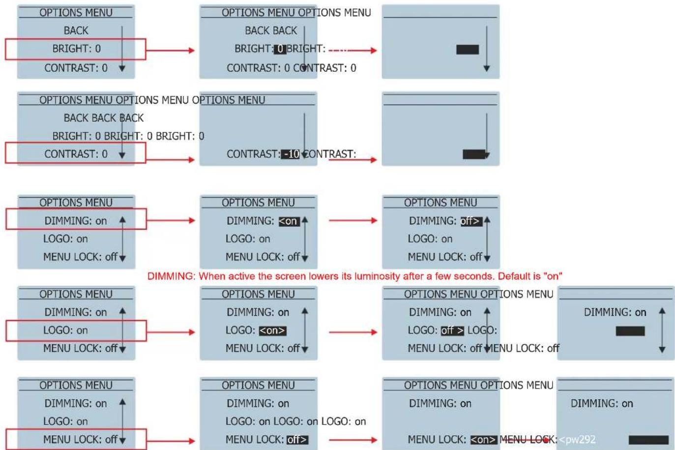
OPTIONS:
In this sub-menu the user can configure all the non-audio related options. Remember that in order to access each parameter it is necessary to push the encoder:
flowchart
graph TD
    A["OPTIONS MENU"] --> B["BACK"]
    B --> C["BRIGHT: 0"]
    C --> D["CONTRAST: 0"]
    D --> E["OPTIONS MENU OPTIONS MENU"]
    E --> F["BACK BACK"]
    F --> G["BRIGHT: 0"]
    G --> H["CONTRAST: 0"]
    H --> I["OPTIONS MENU OPTIONS MENU OPTIONS MENU"]
    I --> J["BACK BACK BACK"]
    J --> K["BRIGHT: 0"]
    K --> L["CONTRAST: 0"]
    L --> M["OPTIONS MENU OPTIONS MENU OPTIONS MENU"]
    M --> N["CONTRAST: -10"]
    N --> O["OPTIONS MENU OPTIONS MENU OPTIONS MENU"]
    O --> P["DIMMING: on"]
    P --> Q["LOGO: on"]
    Q --> R["MENU LOCK: off"]
    R --> S["OPTIONS MENU OPTIONS MENU OPTIONS MENU"]
    S --> T["DIMMING: <on"]
    T --> U["LOGO: on"]
    U --> V["MENU LOCK: off"]
    V --> W["OPTIONS MENU OPTIONS MENU OPTIONS MENU"]
    W --> X["DIMMING: on"]
    X --> Y["LOGO: on"]
    Y --> Z["MENU LOCK: off"]
    Z --> AA["OPTIONS MENU OPTIONS MENU OPTIONS MENU"]
    AA --> AB["DIMMING: on"]
    AB --> AC["LOGO: on"]
    AC --> AD["MENU LOCK: off"]
    AD --> AE["OPTIONS MENU OPTIONS MENU OPTIONS MENU"]
    AE --> AF["DIMMING: on"]
    AF --> AG["LOGO: on"]
    AG --> AH["MENU LOCK: off"]
    AH --> AI["OPTIONS MENU OPTIONS MENU OPTIONS MENU"]
    AI --> AJ["DIMMING: on"]
    AJ --> AK["LOGO: on"]
    AK --> AL["MENU LOCK: off"]
    AL --> AM["OPTIONS MENU OPTIONS MENU OPTIONS MENU"]
    AM --> AN["DIMMING: on"]
    AN --> AO["LOGO: on"]
    AO --> AP["MENU LOCK: off"]
    AP --> AQ["OPTIONS MENU OPTIONS MENU OPTIONS MENU"]
    AQ --> AR["DIMMING: on"]
    AR --> AS["LOGO: on"]
    AS --> AT["MENU LOCK: off"]
    AT --> AU["OPTIONS MENU OPTIONS MENU OPTIONS MENU"]
A. User can LOCK the Display and Master Volume Control by enabling this option MENU LOCK: ON
B. User can LOCK the Display and Master Volume Control WITH PASSWORD by enabling this option MENU LOCK: pw292
In case A to unlock just press the encoder: In case B to unlock PUSH encoder and enter the 3 digit password (292):
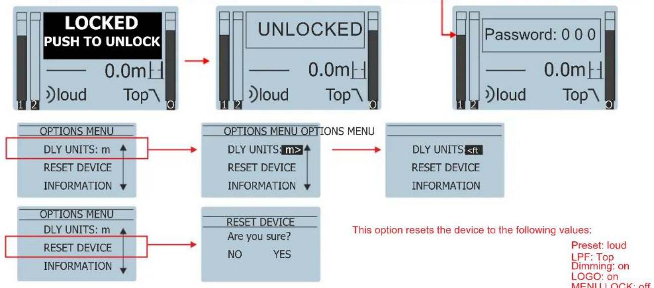
flowchart
graph TD
    A["LOCKED PUSH TO UNLOCK\n0.0m\nloud Top\n0"] --> B["UNLOCKED\n0.0m\nloud Top\n0"]
    B --> C["Password: 0 0 0\n0.0m\nloud Top\n0"]
    C --> D["OPTIONS MENU\nDLY UNITS: m\nRESET DEVICE\nINFORMATION"]
    D --> E["OPTIONS MENU OPTIONS MENU\nDLY UNITS: m>\nRESET DEVICE\nINFORMATION"]
    E --> F["DLY UNITS <ft\nRESET DEVICE\nINFORMATION"]
    F --> G["OPTIONS MENU\nDLY UNITS: m\nRESET DEVICE\nINFORMATION"]
    G --> H["RESET DEVICE\nAre you sure?\nNO YES"]
    H --> I["This option resets the device to the following values:\nPreset: loud\nLPF: Top\nDimming: on\nLOGO: on\nMENU LOCK: off"]
RIGGING
Warnings
This manual contains needed information for flying DAS Audio line array systems, description of the elements and safety precautions. To perform any operations related to flying the system, read the present document first, and act on the warnings and advice given. The goal is to allow the user to become familiar with the mechanical elements required to fly the acoustic system, as well as the safety measures to be taken during set-up and teardown.
Only experienced installers with adequate knowledge of the equipment and local safety regulations should fly speaker boxes. It is the user's responsibility to ensure that the systems to be flown (including flying accessories) comply with state and local regulations.
The working load limits in this manual are the results of tests by independent laboratories. It is the user's responsibility to stay within safe limits. It is the user's responsibility to follow and comply with safety factors, resistance values, periodical supervisions and warnings given in this manual. Product improvement by means of research and development is on going at DAS. Specifications are subject to change without notice.
It is common practice to apply 5:1 safety factors for enclosures and static elements. For slings and elements exposed to material fatigue due to friction and load variation the following ratios must be met; 5:1 for steel cable slings, 4:1 for steel chain slings and 7:1 polyester slings. Thus, an element with a breaking load limit of 1000 kg may be statically loaded with 200 kg (5:1 safety factor) and dynamically loaded with 142 kg (7:1 safety factor).
When flying a system, the working load must be lower than the resistance of each individual flying point in the enclosure, as well as each box. Hanging hardware should be regularly inspected and suspect units replaced if in doubt. This is important to avoid injury and absolutely no risks should be taken in this respect. It is highly recommended that you implement an inspection and maintenance program on flying elements, including reports to be filled out by the personnel that will carry out the inspections. Local regulations may exist that, in case of accident, may require you to present evidence of inspection reports and corrective actions after defects were found.
Absolutely no risks should be taken with regards to public safety. When flying enclosures from ceiling support structures, extreme care should be taken to assure the load bearing capabilities of the structures so that the installation is absolutely safe. Do not fly enclosures from unsafe structures. Consult a certified professional if needed. All flying accessories that are not supplied by DAS Audio are the user's responsibility. Use at your own risk.
Introduction
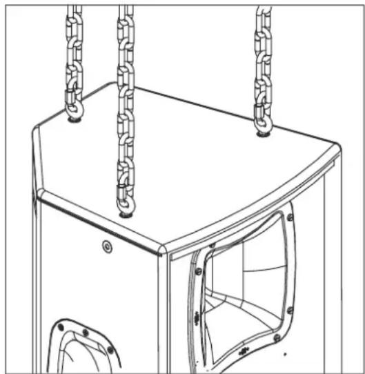
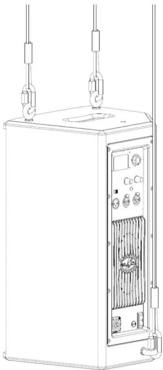
Flyable action 500 series models feature 6 internal steel angles, with 2 mounting threads each, so that 12 flying points are available (2 on each side, 3 on the top panel and 3 on the bottom panel and 2 on the rear panel). Eyebolt flying points are factory sealed with M10 screws, which are replaced with eyebolts on the flying points as required. Flying with eyebolts is very economical and safe, and is specially recommended for fixed installations where the boxes are permanently fixed.
The illustration shows the internal metal hardware of an enclosure with eyebolt flying.
natural_image
Technical line drawing of a mechanical device with hanging chains and a central opening (no text or symbols)Flying with eyebolts
The Allen-head screws must be removed and replaced by M10 eyebolts on one side of the enclosure. Each rigging point has 200 kg (440 lb) working load limit. Then choose the slings or chains of required load resistance and length, bearing in mind that the length difference between the front and back slings or chains will determine the vertical orientation. Alternatively, the back bottom eyebolt points can be used to provide vertical orientation.
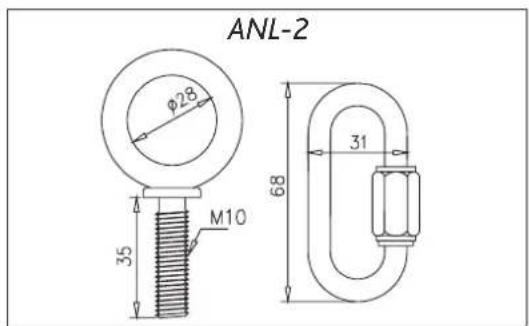
The ANL-2 set is an optional set of four eyebolts and four carabiners. (Dimensions are in millimetres).
text_image
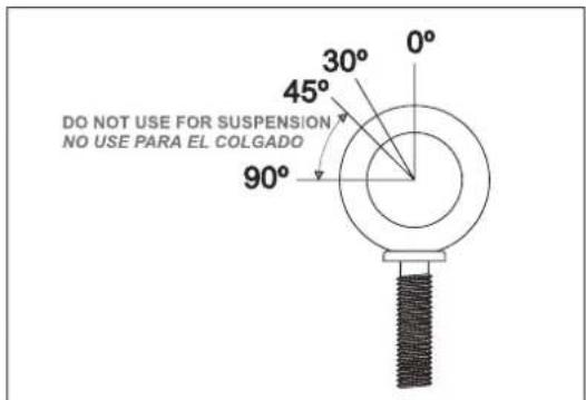
DO NOT USE FOR SUSPENSION NO USE PARA EL COLGADOThe following illustrations show different views on eyebolt flying for a single box. The length of the back cables or chains determines the vertical angle of the box.
text_image
ANL-2 φ28 35 M10 68 31Each ANL-2 eyebolt has a rated working load of 200 kg. (440 lb). Each ANL-2 carabiner has a working load of 330 kg (726 lb). If using other hardware, make sure it is rated to handle the required load.
When using eyebolts it is important to bear in mind that the rated working load is only true for a load applied in the plane of the eye, and is significantly reduced for other angles. The drawing illustrates the concept. The table shows the variation of the working load as a function of the load angle. In the case of the ANL-2 eyebolt, this means that the 200 kg working load becomes 60 kg at 45 degrees. Do not use eyebolt flying if the load angle is higher than 45 degrees.
| 0 Degrees | 30 Degrees 45 | Degrees | More than 45 Degrees | |
| % Working load | 100% | 65% | 30% | 25% |
natural_image
Line drawing of a portable industrial control unit with hanging cables and internal components (no text or symbols)RIGGING (cont'd)
Instructions for AXU (only ACTION-508 and ACTION-512 enclosures)
Introduction
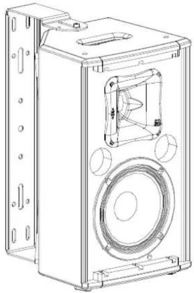
The AXU-ACT8 are designed for ACTION-508 and ACTION-508A enclosures.
The AXU-ACT12 are designed for ACTION-512 and ACTION-512A enclosures.
Safety Precautions
Wall plugs provided are to be used in brick walls only. For other wall materials, source the suitable wall plug before use.
DAS Audio is not responsible for use other than the recommended or whether it be the result of insufficient strength of the support structure. Use only the screws and wall plugs supplied on surfaces that will provide sufficient support. Do not use on surfaces such as plaster, and gypsum. It is highly recommended and in most parts of the world mandatory, that a safety cable be used to secure the enclosure to the structure.
To ensure optimum safety, the installation should be checked thoroughly at regular intervals replacing all deteriorated elements.
Loosen the screws before reorienting the speaker. Never force the rigging elements.
Contact a licensed rigger if there is any doubt.
natural_image
Technical line drawing of a speaker enclosure with mounting brackets and central speaker (no text or symbols)Mounting instructions
You can consult the AXU-ACT8 mounting instructions for ACTION-508A enclosures on the web: www.dasaudio.com
You can consult the AXU-ACT12 mounting instructions for ACTION-512A enclosures on the web: www.dasaudio.com
TRD-6 / TRD-7 accessories
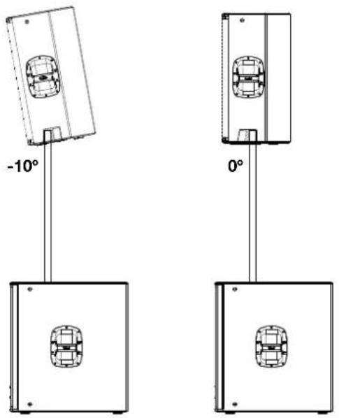
The models ACTION-512A and ACTION-515A dispose the 35mm tripod socket with angle double (0° and -10°) for stand mounting.
natural_image
Diagram showing two car-mounted sensors with 10° and 0° angles, no text or symbols presentANNEX: Line connections: unbalanced and balanced
There are two basic ways to transport an audio signal with microphone or line level:
Unbalanced line: Utilising a two conductor cable, it transports the signal as the voltage between them. Electromagnetic interference can get added to the signal as undesired noise. Connectors that carry unbalanced signals have two pins, such as RCA (Phono) and 14 " (6.35mm, often referred to as jack) mono. 3 pin connector such as XLR (Cannon) may also carry unbalanced signals if one of the pins is unused.
Balanced line: Utilising a three conductor cable, one of them acts as a shield against electromagnetic noise and is the ground conductor. The other two have the same voltage with respect to the ground conductor but with opposite signs. The noise that cannot be rejected by the shield affects both signal conductors in the same way. At the device's input the two signals get summed with opposite sign, so that noise is cancelled out while the programme signal doubles in level. Most professional audio devices use balanced inputs and outputs. Connectors that can carry balanced signal have three pins, such as XLR (Cannon) and 14 " (6.35mm) stereo.
The graphs that follow show the recommended connection with different types of connectors to balanced processor or amplifier inputs. The connectors on the left-hand side come from a signal source, and the ones on the right hand side go to the inputs of the processor or amplifier. Note that on the unbalanced connectors on the left-hand side, two terminals are joined inside the connector. If hum occurs with balanced to balanced connections, try disconnecting the sleeve (ground) on the input connector. Note that the illustrations show what should be connected to what, but that pin locations on an actual XLR connector are different. Also, pin 2 hot is assumed on XLR connectors.

text_image
Balanced XLR (Cannon) to Balanced XLR
text_image
Unbalanced XLR (Cannon) to Balanced XLR
text_image
T R S T R S R S Balanced 1/4" (Jack) to Balanced XLR (Cannon) 2 1 3
text_image
Unbalanced 1/4" Jack to Balanced XLR (Cannon)
text_image
T S T S RCA (Phono) to Balanced XLR (Cannon) 2 1 3
text_image
T R S T R S R S Balanced 1/4" (Jack) to Balanced 1/4" (Jack) S R T
text_image
Unbalanced 1/4" (Jack) to Balanced 1/4" (Jack)
text_image
T S T S RCA (Phono) to Balanced 1/4" (Jack) S R T
text_image
D.A.S.www.dasaudio.com