
F3F - Laptop ASUS - Free user manual and instructions
Find the device manual for free F3F ASUS in PDF.


User questions about F3F ASUS
0 question about this device. Answer the ones you know or ask your own.
Ask a new question about this device
Download the instructions for your Laptop in PDF format for free! Find your manual F3F - ASUS and take your electronic device back in hand. On this page are published all the documents necessary for the use of your device. F3F by ASUS.
USER MANUAL F3F ASUS
Notebook PC Hardware User's Manual
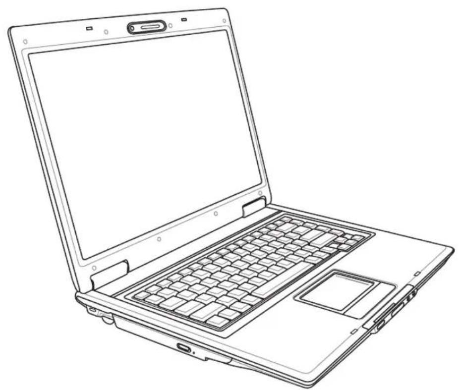
natural_image
Line drawing of a laptop computer with visible keyboard, drive pad, and open screen (no text or symbols)Contents
1. Introducing the Notebook PC ....5
About This User's Manual 6
Notes For This Manual 6
Preparing your Notebook PC....9
2. Knowing the Parts 11
Top Side....12
Bottom Side....14
Front Side....16
Left Side 17
Right Side....18
Rear Side....20
3. Getting Started ....21
Power System 22
Using AC Power 22
Using Battery Power 23
Battery Care....23
Powering ON the Notebook PC 24
The Power-On Self Test (POST) 24
Checking Battery Power 25
Charging the Battery Pack 25
Restarting or Rebooting 26
Powering OFF 26
Special Keyboard Functions 27
Colored Hot Keys 27
Microsoft Windows Keys 29
Keyboard as a Numeric Keypad 29
Keyboard as Cursors 29
Switches and Status Indicators 30
Switches....30
Status Indicators 32
CD Player Control Buttons & Indicator (on selected models) 33
4. Using the Notebook PC ....35
Operating System....36
Support Software 36
Automatic Touchpad Disabling (on selected models) 36
Pointing Device....37
Using the Touchpad 37
Touchpad Usage Illustrations 38
Caring for the Touchpad 39
Storage Devices 40
ExpressCard 40
Optical Drive 41
Flash Memory Card Reader ....43
Hard Disk Drive 43
Connections....44
Modem Connection 44
Network Connection ....45
Wireless LAN Connection (on selected models) 46
Bluetooth Wireless Connection (on selected models) 47
Trusted Platform Module (TPM) (on selected models) 48
Power Management Modes.... 49
Full Power Mode & Maximum Performance 49
ACPI....49
Suspend Mode 49
Power Savings 49
Power State Summary 50
Thermal Power Control 50
Stand by and Hibernate 51
Appendix 53
Optional Accessories 54
Glossary 58
Declarations and Safety Statements 62
Notebook PC Information 74
Contents
1. Introducing the Notebook PC
About This User's Manual
Notes For This Manual
Safety Precautions
Preparing your Notebook PC
1
Introducing the Notebook PC
About This User's Manual
You are reading the Notebook PC User's Manual. This User's Manual provides information on the various components in the Notebook PC and how to use them. The following are major sections of this User's Manuals:

1. Introducing the Notebook PC
Introduces you to the Notebook PC and this User's Manual.
2. Knowing the Parts
Gives you information on the Notebook PC's components.
3. Getting Started
Gives you information on getting started with the Notebook PC.
4. Using the Notebook PC
Gives you information on using the Notebook PC's components.
5. Appendix
Introduces you to optional accessories and gives additional information.
Notes For This Manual
A few notes and warnings in bold are used throughout this guide that you should be aware of in order to complete certain tasks safely and completely. These notes have different degrees of importance as described below:

WARNING! Important information that must be followed for safe operation.

TIP: Tips and useful information for completing tasks.

IMPORTANT! Vital information that must be followed to prevent damage to data, components, or persons.

NOTE: Tips and information for special situations.

Text enclosed in <> or [] represents a key on the keyboard; do not actually type the <> or [] and the enclosed letters.
Safety Precautions
The following safety precautions will increase the life of the Notebook PC. Follow all precautions and instructions. Except as described in this manual, refer all servicing to qualified personnel. Do not use damaged power cords, accessories, or other peripherals. Do not use strong solvents such as thinners, benzene, or other chemicals on or near the surface.

IMPORTANT! Disconnect the AC power and remove the battery pack(s) before cleaning. Wipe the Notebook PC using a clean cellulose sponge or chamois cloth dampened with a solution of nonabrasive detergent and a few drops of warm water and remove any extra moisture with a dry cloth.

DO NOT place on uneven or unstable work surfaces. Seek servicing if the casing has been damaged.

DO NOT place or drop objects on top and do not shove any foreign objects into the Notebook PC.
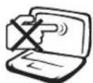
DO NOT press or touch the display panel. Do not place together with small items that may scratch or enter the Notebook PC.
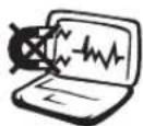
DO NOT expose to strong magnetic or electrical fields.
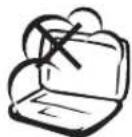
DO NOT expose to dirty or dusty environments. DO NOT operate during a gas leak.
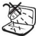
DO NOT expose to or use near liquids, rain, or moisture. DO NOT use the modem during an electrical storm.
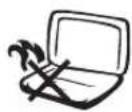
DO NOT leave the Notebook PC on your lap or any part of the body in order to prevent discomfort or injury from heat exposure.
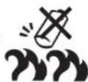
Battery safety warning: DO NOT throw the battery in fire. DO NOT short circuit the contacts. DO NOT disassemble the battery.
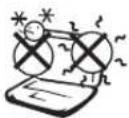
SAFE TEMP: This Notebook PC should only be used in environments with ambient temperatures between 5°C (41°F) and 35°C (95°F)
INPUT RATING: Refer to the rating label on the bottom of the Notebook PC and be sure that your power adapter complies with the rating.
DO NOT throw the Notebook PC in municipal waste. Check local regulations for disposal of electronic products.
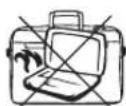
DO NOT carry or cover a Notebook PC that is powered ON with any materials that will reduce air circulation such as a carrying bag.

Transportation Precautions
To prepare the Notebook PC for transport, you should turn it OFF and disconnect all external peripherals to prevent damage to the connectors. The hard disk drive's head retracts when the power is turned OFF to prevent scratching of the hard disk surface during transport. Therefore, you should not transport the Notebook PC while the power is still ON. Close the display panel and check that it is latched securely in the closed position to protect the keyboard and display panel.
Cover Your Notebook PC
You can purchase an optional carrying case to protect it from dirt, water, shock, and scratches.

CAUTION: The Notebook PC's surface is easily dulled if not properly cared for. Be careful not to rub or scrape the Notebook PC surfaces when transporting your Notebook PC.

Charge Your Batteries
If you intend to use battery power, be sure to fully charge your battery pack and any optional battery packs before going on long trips. Remember that the power adapter charges the battery pack as long as it is plugged into the computer and an AC power source. Be aware that it takes much longer to charge the battery pack when the Notebook PC is in use.

Airplane Precautions
Contact your airline if you want to use the Notebook PC on the airplane. Most airlines will have restrictions for using electronic devices. Most airlines will allow electronic use only between and not during takeoffs and landings.

CAUTION! There are three main types of airport security devices: X-ray machines (used on items placed on conveyor belts), magnetic detectors (used on people walking through security checks), and magnetic wands (hand-held devices used on people or individual items). You can send your Notebook PC and diskettes through airport X-ray machines. However, it is recommended that you do not send your Notebook PC or diskettes through airport magnetic detectors or expose them to magnetic wands.
Preparing your Notebook PC
These are only quick instructions for using your Notebook PC. Read the later pages for detailed information on using your Notebook PC.
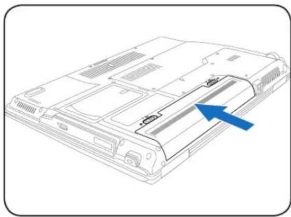
1. Install the battery pack
natural_image
Line drawing of a computer chassis with a blue arrow pointing to a component (no text or symbols present)2. Connect the AC Power Adapter
text_image
Diagram of a device cable assembly with labeled components and directional arrows indicating connection points3. Open the Display Panel 4. Turn ON the Notebook PC
natural_image
Line drawing of hands installing a laptop keyboard with blue arrows indicating press direction (no text or symbols)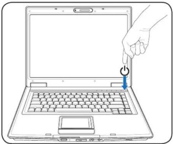
natural_image
Line drawing of a hand pressing a button on a laptop keyboard, with no text or symbols present.
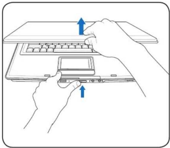
IMPORTANT! When opening, do not force the display panel down to the table or else the hinges may break! Never lift the Notebook PC by the display panel!
Press the power button and release.
(In Windows XP, this button can also be used to safely turn OFF the Notebook PC.)
1
Introducing the Notebook PC
2. Knowing the Parts
Basic sides of the Notebook PC
Top Side
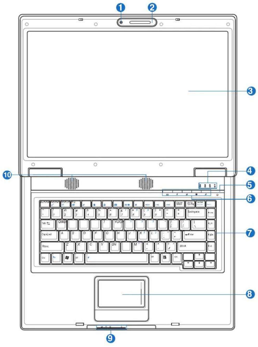
Refer to the diagram below to identify the components on this side of the Notebook PC.
text_image
Laptop keyboard diagram with numbered annotations pointing to key components such as QWEP, Open, and Start.
NOTE: The keyboard will be different for each territory.
1 Camera (on selected models)
The built-in camera allows picture taking or video recording. Can be used with video conferencing and other interactive applications.
2 Microphone (Built-in)
The built-in mono microphone can be used for video conferencing, voice narrations, or simple audio recordings.

3 □ Display Panel
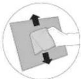
The display panel functions the same as a desktop monitor. The Notebook PC uses an active matrix TFT LCD, which provides excellent viewing like that of desktop monitors. Unlike desktop monitors, the LCD panel does not produce any radiation or flickering, so it is easier on the eyes. Use a soft cloth without chemical liquids (use plain water if necessary) to clean the display panel.
4 Status Indicators (top)
Status indicator details are described in section 3.
5 Power Switch
The power switch allows powering ON and OFF the Notebook PC and recovering from STD. Use the switch once to turn ON and once to turn OFF the Notebook PC. In Windows XP, this button can also be used to safely turn OFF the Notebook PC. The power switch only works when the display panel is opened.
6 Instant Keys
Instant keys allow you to launch frequently used applications with one push of a button. Details are described in section 3.
7 Keyboard
The keyboard provides full-sized keys with comfortable travel (depth at which the keys can be depressed) and palm rest for both hands. Two Windows function keys are provided to help ease navigation in the Windows operating system.
8 Touchpad and Buttons
The touchpad with its buttons is a pointing device that provides the same functions as a desktop mouse. A software-controlled scrolling function is available after setting up the included touchpad utility to allow easy Windows or web navigation.
9 Status Indicators (front)
Status indicator details are described in section 3.
10 Audio Speakers
The built-in stereo speaker system allows you to hear audio without additional attachments. The multimedia sound system features an integrated digital audio controller that produces rich, vibrant sound (results improved with external stereo headphones or speakers). Audio features are software controlled.

2
Knowing the Parts
Bottom Side
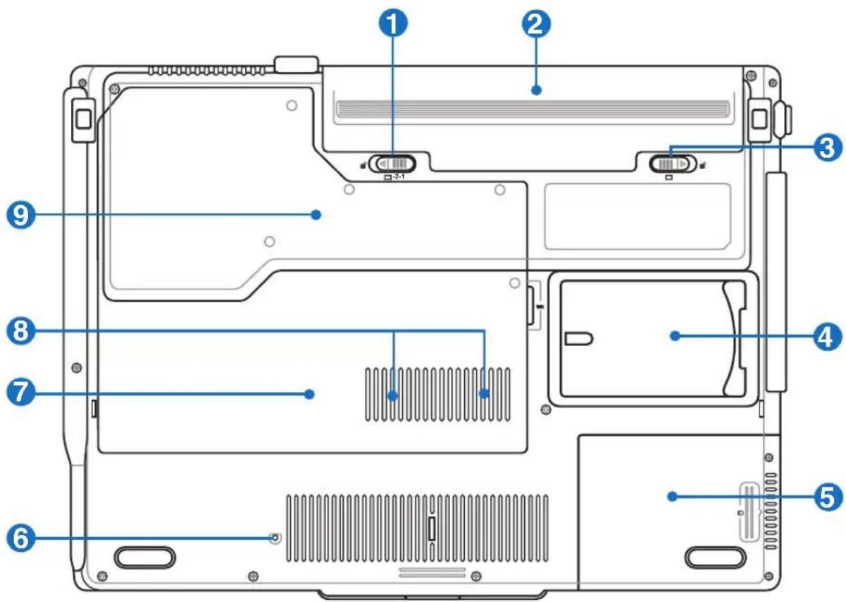
Refer to the diagram below to identify the components on this side of the Notebook PC.

NOTE: The bottom side may vary in appearance depending on model.
text_image
Labeled diagram of a computer chassis showing internal components and connectors
WARNING! The bottom of the Notebook PC can get very hot. Be careful when handling the Notebook PC while it is in operation or recently been in operation. High temperatures are normal during charging or operation. Do not use on soft surfaces such as beds or sofas which may block the vents. DO NOT PUT THE NOTEBOOK PC ON YOUR LAP OR OTHER PARTS OF THE BODY TO AVOID INJURY FROM THE HEAT.
Battery Lock - Spring
The spring battery lock is used to keep the battery pack secured. When the battery pack is inserted, it will automatically lock. To remove the battery pack, this spring lock must be held in the unlocked position.
Battery Pack
The battery pack is automatically charged when connected to an AC power source and maintains power to the Notebook PC when AC power is not connected. This allows use when moving temporarily between locations. Battery time varies by usage and by the specifications for this Notebook PC. The battery pack cannot be disassembled and must be purchased as a single unit.
Battery Lock - Manual
The manual battery lock is used to keep the battery pack secured. Move the manual lock to the unlocked position to insert or remove the battery pack. Move the manual lock to the locked position after inserting the battery pack.
4 Name Card Holder
The Notebook PC has a name card holder glued to the bottom of the Notebook PC to hold identification information on the user in case the Notebook PC is found by others.
5 Hard Disk Drive Compartment
The hard disk drive is secured in a compartment. Hard disk drive upgrades are to be done by authorized service centers or dealers only.
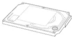
6 ▶ Shutdown Button (Emergency)
In case your operating system cannot properly turn OFF or restart, the shutdown button can be pressed with a straightened paper clip to shutdown the Notebook PC.
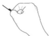
7 PCI Wireless LAN (WLAN) Compartment
The WLAN compartment allows the installation of a wireless networking card in order to wirelessly connect to network access points or other wireless networking devices.
8 Memory (RAM) Compartment
The memory compartment provides expansion capabilities for additional memory. Additional memory will increase application performance by decreasing hard disk access. The BIOS automatically detects the amount of memory in the system and configures CMOS accordingly during the POST (Power-On-Self-Test) process. There is no hardware or software (including BIOS) setup required after the memory is installed. Visit an authorized service center or retailer for information on memory upgrades for your Notebook PC. Only purchase expansion modules from authorized retailers of this Notebook PC to ensure maximum compatibility and reliability.
9 Central Processor Unit (CPU) Compartment
Some Notebook PC models feature a socketed-processor design to allow upgrading to faster processors in the future. Some models feature a ULV design for compactness and may not be upgraded. Visit an authorized service center or retailer for information on upgrades.

WARNING! End-user removal of the CPU or hard disk drive will void the warranty.
2
Knowing the Parts
Front Side
Refer to the diagram below to identify the components on this side of the Notebook PC.

text_image
PUSH OK1 Wireless Switch
Enables or disables the built-in wireless LAN and Bluetooth (selected models). When enabled, the wireless status indicator will light. Windows software settings are necessary before use.
2 □ Display Panel Button
Press the display panel button to open the display panel.

WARNING! When opening, do not force the display panel down to the table or else the hinges may break! Never lift the Notebook PC by the display panel!
3 Microphone Input Jack
The mono microphone jack (1/8 inch) can be used to connect an external microphone or output signals from audio devices. Using this jack automatically disables the built-in microphone. Use this feature for video conferencing, voice narrations, or simple audio recordings.

4 SPDIF Output Jack
This jack provides connection to SPDIF (Sony/Philips Digital Interface) compliant devices for digital audio output. Use this feature to turn the Notebook PC into a hi-fi home entertainment system.

Headphone Output Jack
The stereo headphone jack (1/8 inch) is used to connect the Notebook PC's audio out signal to amplified speakers or headphones. Using this jack automatically disables the built-in speakers.
5 Flash Memory Slot
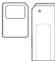
Normally a PCMCIA or USB memory card reader must be purchased separately in order to use memory cards from devices such as digital cameras, MP3 players, mobile phones, and PDAs. This Notebook PC has a built-in memory card reader that can read many flash memory cards as specified later in this manual. The built-in memory card reader is not only convenient, but also faster than most other forms of memory card readers because it utilizes the high-bandwidth PCI bus.
Left Side
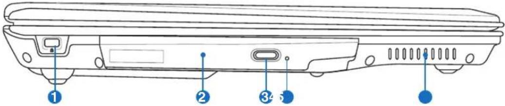
Refer to the diagram below to identify the components on this side of the Notebook PC.
text_image
Technical diagram of a device rear panel with numbered component labels1 Kensington® Lock Port
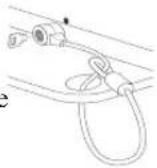
The Kensington® lock port allows the Notebook PC to be secured using Kensington incompatible Notebook PC security products. These security products usually include a metal cable and lock that prevent the Notebook PC to be removed from a fixed object. Some security products may also include a motion detector to sound an alarm when moved.
2 Optical Drive
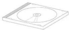
The Notebook PC comes in various models with different optical drives. The Notebook PC's optical drive may support compact discs (CD) and/or digital video discs (DVD) and may have recordable (R) or re-writable (RW) capabilities. See the marketing specifications for details on each model.
3 Optical Drive Electronic Eject
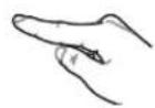
The optical drive eject has an electronic eject button for opening the tray. You can also eject the optical drive tray through any software player or by right clicking the optical drive in Windows™ “My Computer.”
4 ● Optical Drive Emergency Eject (location varies by model)
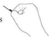
The emergency eject is used to eject the optical drive tray in case the electronic eject does not work. Do not use the emergency eject in place of the electronic eject.
5 Air Vents
The air vents allow cool air to enter and warm air to exit the Notebook PC.

IMPORTANT! Make sure that paper, books, clothing, cables, or other objects do not block any of the air vents or else overheating of the Notebook PC may occur.
2
Knowing the Parts
Right Side
Refer to the diagram below to identify the components on this side of the Notebook PC.
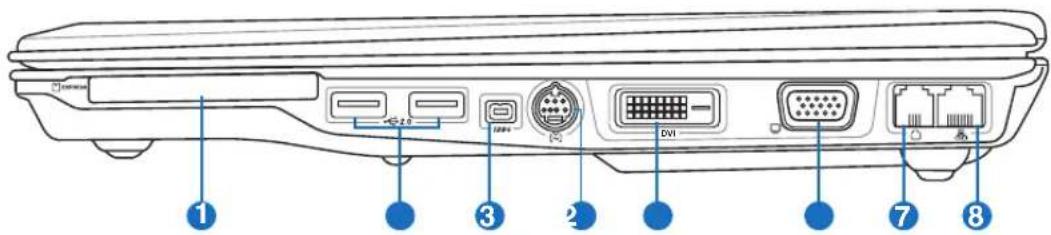
text_image
Diagram of a device rear panel with labeled ports and connectors, including DVI, I/O ports, and network ports.1 ExpressCard Slot
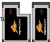
One 26pin Express card slot is available to support one ExpressCard/34mm or one ExpressCard/54mm expansion card. This new interface is faster by using a serial bus supporting USB 2.0 and PCI Express instead of the slower parallel bus used in the PC card slot. (Not compatible with previous PCMCIA cards.)
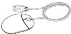
② USB Port (2.0/1.1)
The USB (Universal Serial Bus) port is compatible with USB 2.0 or USB 1.1 devices such as keyboards, pointing devices, cameras, hard disk drives, printers, and scanners connected in a series up to 12Mbits/sec
(USB 1.1) and 480Mbits/sec (USB 2.0). USB allows many devices to run simultaneously on a single computer, with some peripherals acting as additional plug-in sites or hubs. USB supports hot-swapping of devices so that most peripherals can be connected or disconnected without restarting the computer.
3 1394 IEEE1394 Port
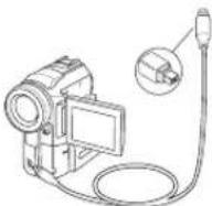
IEEE1394 is a high speed serial bus like SCSI but has simple connections and hot-plugging capabilities like USB. The interface IEEE1394 has a bandwidth of 100-400 Mbits/sec and can handle up to 63 units on the same bus. IEEE1394 is also used in high-end digital equipment and should be marked "DV" for Digital Video port.
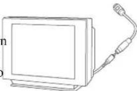
4 TV-Out Port
The TV-Out port is an S-Video connector that allows routing the Notebook PC's display to a television or video projection device. You can choose between simultaneously or single display. Use an S-Video cable (not provided) for high quality displays or use the provided RCA to S-Video adapter for standard video devices. This port supports both NTSC and PAL formats.
natural_image
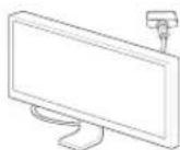
Line drawing of a flat-screen monitor connected to a cable (no text or symbols)5 DVI-D Display (DVI-D) Output (on selected models)
The Digital Video Interface port is designed to maximize video graphics output to flat panel LCD monitors or other DVI-compliant device.
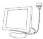
6 □ Display (Monitor) Output
The 15-pin D-sub monitor port supports a standard VGA-compatible device such as a monitor or projector to allow viewing on a larger external display.
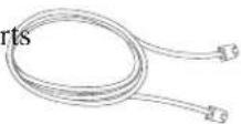
7 Modem Port
The RJ-11 modem port with two pins is smaller than the RJ-45 LAN port and supports a standard telephone cable. The internal modem supports up to 56K V.90 transfers. The built-in connector allows convenient use without additional adapters.

IMPORTANT! The built-in modem does not support the voltage used in digital phone systems. Do not connect the modem port to a digital phone system or else damage will occur to the Notebook PC.
8 LAN Port
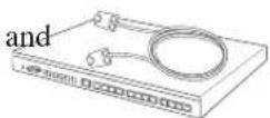
The RJ-45 LAN port with eight pins is larger than the RJ-11 modem port and supports a standard Ethernet cable for connection to a local network. The built-in connector allows convenient use without additional adapters.
2
Knowing the Parts
Rear Side
Refer to the diagram below to identify the components on this side of the Notebook PC.

natural_image
Diagram of a computer monitor rear panel with labeled ports and connectors (no text or symbols beyond labels)1 DCIN Power (DC) Input
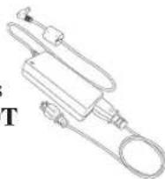
The supplied power adapter converts AC power to DC power for use with this jack. Power supplied through this jack supplies power to the Notebook PC and charges the internal battery pack. To prevent damage to the Notebook PC and battery pack, always use the supplied power adapter. CAUTION: MAY BECOME WARM TO HOT WHEN IN USE. BE SURE NOT TO COVER THE ADAPTER AND KEEP IT AWAY FROM YOUR BODY.
2 Air Vents
The air vents allow cool air to enter and warm air to exit the Notebook PC.

IMPORTANT! Make sure that paper, books, clothing, cables, or other objects do not block any of the air vents or else overheating of the Notebook PC may occur.
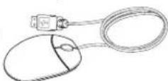
USB Port (2.0/1.1)
The USB (Universal Serial Bus) port is compatible with USB 2.0 or USB 1.1 devices such as keyboards, pointing devices, cameras, hard disk drives, printers, and scanners connected in a series up to 12Mbits/sec
(USB 1.1) and 480Mbits/sec (USB 2.0). USB allows many devices to run simultaneously on a single computer, with some peripherals acting as additional plug-in sites or hubs. USB supports hot-swapping of devices so that most peripherals can be connected or disconnected without restarting the computer.
4 Battery Pack
The battery pack is automatically charged when connected to an AC power source and maintains power to the Notebook PC when AC power is not connected. This allows use when moving temporarily between locations. Battery time varies by usage and by the specifications for this Notebook PC. The battery pack cannot be disassembled and must be purchased as a single unit.
3. Getting Started
Using AC Power
Using Battery Power
Powering ON the Notebook PC
Checking Battery Power
Restarting or Rebooting
Powering OFF the Notebook PC
Special Keyboard Functions
Switches and Status Indicators
Power System

Using AC Power
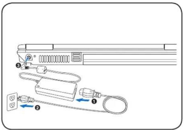
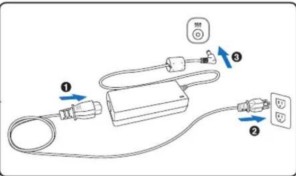
The Notebook PC power is comprised of two parts, the power adapter and the battery power system. The power adapter converts AC power from a wall outlet to the DC power required by the Notebook PC. Your Notebook PC comes with a universal AC-DC adapter. That means that you may connect the power cord to any 100V-120V as well as 220V-240V outlets without setting switches or using power converters. Different countries may require that an adapter be used to connect the provided US-standard AC power cord to a different standard Most hotels will provide universal outlets to support different power cords as well as voltages. It is always best to ask an experienced traveler about AC outlet voltages when bringing power adapters to another country.
text_image
Diagram of a connected electrical device with labeled components and directional arrows indicating connections.
TIP: You can buy travel kits for the Notebook PC that includes power and modem adapters for almost every country.
With the AC power cord connected to the AC-DC converter, connect the AC power cord to an AC outlet (preferably with surge-protection) and then connect the DC plug to the Notebook PC. Connecting the AC-DC adapter to the AC outlet first allows you to test the AC outlet's power and the AC-DC converter itself for compatibility problems before connecting the DC power to the Notebook PC. The green power LED on the adapter lights up if the power is within accepted ranges.

IMPORTANT! Damage may occur if you use a different adapter to power the Notebook PC or use the Notebook PC's adapter to power other electrical devices. If there is smoke, burning scent, or extreme heat coming from the AC-DC adapter, seek servicing. Seek servicing if you suspect a faulty AC-DC adapter. You may damage both your battery pack(s) and the Notebook PC with a faulty AC-DC adapter.

NOTE: This Notebook PC may come with either a two or three-prong plug depending on territory. If a three-prong plug is provided, you must use a grounded AC outlet or use a properly grounded adapter to ensure safe operation of the Notebook PC.

WARNING! THE POWER ADAPTER MAY BECOME WARM TO HOT WHEN IN USE. BE SURE NOT TO COVER THE ADAPTER AND KEEP IT AWAY FROM YOUR BODY.
Using Battery Power
The Notebook PC is designed to work with a removable battery pack. The battery pack consists of a set of battery cells housed together. A fully charged pack will provide several hours of battery life, which can be further extended by using power management features through the BIOS setup. Additional battery packs are optional and can be purchased separately through a Notebook PC retailer.
Installing and Removing the Battery Pack
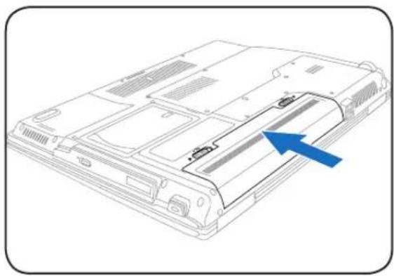
Your Notebook PC may or may not have its battery pack installed. If your Notebook PC does not have its battery pack installed, use the following procedures to install the battery pack.

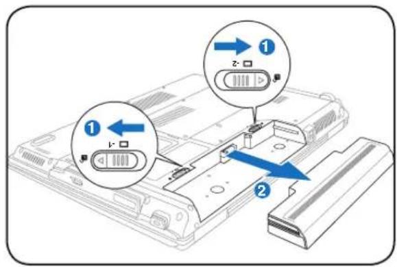
IMPORTANT! Never attempt to remove the battery pack while the Notebook PC is turned ON, as this may result in the loss of working data.
To install the battery pack:
natural_image
Line drawing of a computer chassis with a blue arrow pointing to a component (no text or symbols present)To remove the battery pack:
text_image
Diagram showing two labeled components of a device with directional arrows and component labels in Chinese
IMPORTANT! Only use battery packs and power adapters supplied with this Notebook PC or specifically approved by the manufacturer or retailer for use with this model or else damage may occur to the Notebook PC.
Battery Care
The Notebook PC's battery pack, like all rechargeable batteries, has a limit on the number times it can be recharged. The battery pack's useful life will depend on your environment temperature, humidity, and how your Notebook PC is used. It is ideal that the battery be used in a temperature range between 5^ and 35^ (41°F and 95°F). You must also take into account that the Notebook PC's internal temperature is higher than the outside temperature. Any temperatures above or below this range will shorten the life of the battery. But in any case, the battery pack's usage time will eventually decrease and a new battery pack must be purchased from an authorized dealer for this Notebook PC. Because batteries also have a shelf life, it is not recommended to buy extras for storing.

WARNING! For safety reasons, DO NOT throw the battery in fire, DO NOT short circuit the contacts, and DO NOT disassemble the battery. If there is any abnormal operation or damage to the battery pack caused by impact, turn OFF the Notebook PC and contact an authorized service center.

Powering ON the Notebook PC
The Notebook PC's power-ON message appears on the screen when you turn it ON. If necessary, you may adjust the brightness by using the hot keys. If you need to run the BIOS Setup to set or modify the system configuration, press [F2] upon bootup to enter the BIOS Setup. If you press [Tab] during the splash screen, standard boot information such as the BIOS version can be seen. Press [ESC] and you will be presented with a boot menu with selections to boot from your available drives.

NOTE: Before bootup, the display panel flashes when the power is turned ON. This is part of the Notebook PC's test routine and is not a problem with the display.

IMPORTANT! To protect the hard disk drive, always wait at least 5 seconds after turning OFF your Notebook PC before turning it back ON.

WARNING! DO NOT carry or cover a Notebook PC that is powered ON with any materials that will reduce air circulation such as a carrying bag.
The Power-On Self Test (POST)
When you turn ON the Notebook PC, it will first run through a series of software-controlled diagnostic tests called the Power-On Self Test (POST). The software that controls the POST is installed as a permanent part of the Notebook PC's architecture. The POST includes a record of the Notebook PC's hardware configuration, which is used to make a diagnostic check of the system. This record is created by using the BIOS Setup program. If the POST discovers a difference between the record and the existing hardware, it will display a message on the screen prompting you to correct the conflict by running BIOS Setup. In most cases the record should be correct when you receive the Notebook PC. When the test is finished, you may get a message reporting “No operating system found” if the hard disk was not preloaded with an operating system. This indicates that the hard disk is correctly detected and ready for the installation of a new operating system.
The S.M.A.R.T. (Self Monitoring and Reporting Technology) checks the hard disk drive during POST and gives a warning message if the hard disk drive requires servicing. If any critical hard disk drive warning is given during bootup, backup your data immediately and run Windows disk checking program. To run Window's disk checking program: (1) right-click any hard disk drive icon in "My Computer", (2) choose Properties, (3) click the Tools tab, (4) click Check Now, (5) select a hard disk drive, (6) select Thorough to also check for physical damages, and (7) click Start. Third party disk utilities such as Symantec's Norton Disk Doctor can also perform the same functions but with greater ease and more features.

IMPORTANT! If warnings are still given during bootup after running a software disk checking utility, you should take your Notebook PC in for servicing. Continued use may result in data loss.
Checking Battery Power
The battery system implements the Smart Battery standard under the Windows environment, which allows the battery to accurately report the amount of charge left in the battery. A fully-charged batter pack provides the Notebook PC a few hours of working power. But the actual figure varies depending on how you use the power saving features, your general work habits, the CPU, system memory size, and the size of the display panel.
To check the remaining battery power, move your cursor over the power icon. The power icon is a "battery" when not using AC power and a "plug" when using AC power. Double click on the icon for more information and settings.
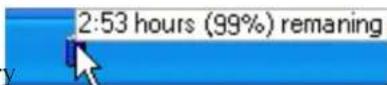
Move your mouse over the battery icon for remaining power information.
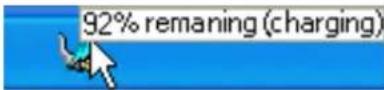
When the AC power is connected, charging status will be shown.

NOTE: You will be warned when battery power is low. If you continue to ignore the low battery warnings, the Notebook PC eventually enters suspend mode (Windows default uses STR).

Note: Screen captures shown here are examples only and may not reflect what you see in your system.
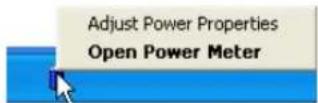
Right-click the battery icon for sub-menus.
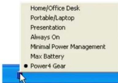
text_image
Home/Office Desk Portable/Laptop Presentation Always On Minimal Power Management Max Battery ● Power4 GearLeft-click the battery icon for power management settings.

WARNING! Suspend-to-RAM (STR) does not last long when the battery power is depleted. Suspend-to-Disk (STD) is not the same as power OFF. STD requires a small amount of power and will fail if no power is available due to complete battery depletion or no power supply (e.g. removing both the power adapter and battery pack).
Charging the Battery Pack
Before you use your Notebook PC on the road, you will have to charge the battery pack. The battery pack begins to charge as soon as the Notebook PC is connected to external power using the power adapter. Fully charge the battery pack before using it for the first time. A new battery pack must completely charge before the Notebook PC is disconnected from external power. It takes a few hours to fully charge the battery when the Notebook PC is turned OFF and may take twice the time when the Notebook PC is turned ON. The battery charge light turns OFF when the battery pack is charged.

NOTE: The battery stops charging if the temperature is too high or the battery voltage is too high. BIOS provides a smart battery refreshing function. If the battery calibration process fails, stop charging and contact an authorized service center.

WARNING! Do not leave the battery pack discharged. The battery pack will discharge over time. If not using a battery pack, it must continued to be charged every three months to extend recovery capacity or else it may fail to charge in the future.
3
Getting Started
start
Restarting or Rebooting
After making changes to your operating system, you may be prompted to restart the system. Some installation processes will provide a dialog box to allow restart. To restart the system manually, click Windows Start button and select Shut Down and then choose Restart.
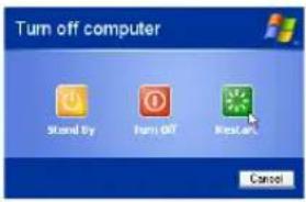
text_image
Turn off computer Stand by Turn Off Restart Cancel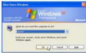
text_image
Shut Down Windows Copyright: 100.00 Microsoft Windows What do you and the computer to set? Select Ask your server, shuts down Windows, and starts Windows agents. OK Cancel Help(Screens are different depending on security settings.)
Powering OFF
In Windows XP, power OFF the Notebook PC by clicking Windows Start button and select Shut Down and then choose Turn off (or Shut down). For operating systems without proper power management (DOS, Windows NT), you must close all applications
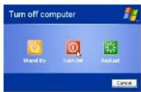
text_image
Turn off computer Stand by Turn Off Restart Cancel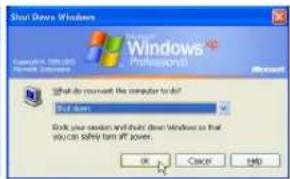
text_image
Short Drive Windows Microsoft Windows Professional What do you want the computer to do? Bud down You can access and/or buy short Windows so that you can safely turn IP power. OK Cancel Helpand exit operating systems and then power OFF by holding the power switch for 2 seconds (as opposed to 1 second to power ON). Holding the power switch for 2 seconds is necessary in order to prevent accidental power-OFFs.

IMPORTANT! To protect the hard drive, wait at least 5 seconds after turning OFF your Notebook PC before turning it back ON.
Emergency Shutdown
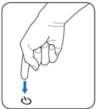
In case your operating system cannot properly turn OFF or restart, there are two additional ways to shutdown your Notebook PC:
(1) Hold the power button over 4 seconds, or (2) Press the shutdown button.
natural_image
Illustration of a hand pointing to a button with a blue arrow indicating downward motion (no text or symbols)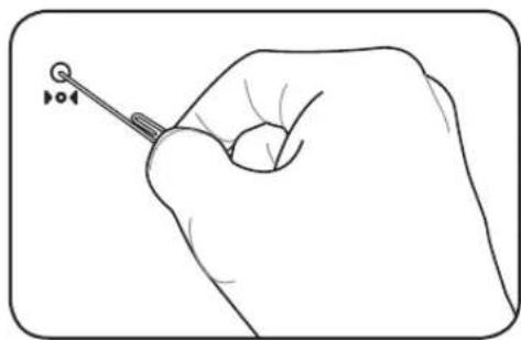
natural_image
Line drawing of a hand holding a small tool with a circular head and pointer (no text or symbols)
TIP: Use a straightened paper clip to press the shutdown button.

IMPORTANT! Do not use emergency shutdown while data is being written; doing so can result in loss or destruction of your data.
Special Keyboard Functions
Colored Hot Keys
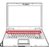
The following defines the colored hot keys on the Notebook PC's keyboard. The colored commands can only be accessed by first pressing and holding the function key while pressing a key with a colored command.

NOTE: The Hot Key locations on the function keys may vary depending on model but the functions should remain the same. Follow the icons instead of the function keys.


“Zz” Icon (F1): Places the Notebook PC in suspend mode (either Save-to-RAM or Save-to-Disk depending on sleep button setting in power management setup).


Radio Tower (F2): Wireless Models Only: Toggles the internal wireless LAN or Bluetooth (on selected models) ON or OFF with an on-screen-display. When enabled, the corresponding wireless indicator will light. Windows software settings are necessary to use the wireless LAN or Bluetooth.


Envelope Icon (F3): Pressing this button will launch your Email application while Windows is running.


“e” Icon (F4): Pressing this button will launch your Internet browser application while Windows is running.


Filled Sun Icon (F5):
Decreases the display brightness


Open Sun Icon (F6):
Increases the display brightness


LCD Icon (F7): Toggles the display panel ON and OFF. This also stretches your screen area (on certain models) to fill the entire display when using low resolution modes.


LCD/Monitor Icons (F8): Toggles between the Notebook PC's LCD display and an external monitor in this series: Notebook PC LCD -> External Monitor -> Both. (This function does not work in 256 Colors, select High Color in Display Property Settings.) IMPORTANT: Connect an external monitor before booting up the Notebook PC.


Crossed-out Touchpad (F9): Toggles the built-in touchpad LOCKED (disabled) and UN-LOCKED (enabled). Locking the touchpad will prevent you from accidentally moving the cursor while typing and is best used with an external pointing device such as a mouse. Note: An indicator between the touchpad buttons will light when the touchpad is UNLOCKED (enabled) and not light when the touchpad is LOCKED (disabled).


Speaker Icons (F10):
Toggles the speakers ON and OFF (only in Windows OS)
Colored Hot Keys (Cont.)


Speaker Down Icon (F11):
Decreases the speaker volume (only in Windows OS)


Speaker Up Icon (F12):
Increases the speaker volume (only in Windows OS)


Num Lk (Ins): Toggles the numeric keypad (number lock) ON and OFF. Allows you to use a larger portion of the keyboard for number entering.


Scr Lk (Del): Toggles the "Scroll Lock" ON and OFF. Allows you to use a larger portion of the keyboard for cell navigation.


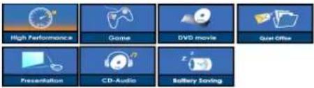
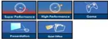
Power4 Gear+ (Fn+Space Bar): The Power4 Gear+ button toggles power savings between various power saving modes. The power saving modes control many aspects of the Notebook PC to maximize performance versus battery time.
When you are using an AC power adapter, Power4 Gear+ will switch between modes in the AC power mode segment. When you remove the AC adapter, Power4 Gear+ will switch between modes in the battery (DC) mode segment. When you remove or apply the AC adapter, Power4 Gear+ will automatically shift you up or down into the proper mode segment (AC or DC).
| Battery Mode AC Mode | |
 |  |


Fn+C: Toggles "Splendid Video Intelligent Technology" function ON and OFF. This allows switching between different display color enhancement modes in order to improve contrast, brightness, skin tone, and color saturation for red, green, and blue independently. You can see the current mode through the on-screen display (OSD).

text_image
OSD Icons Normal Gamma Correction Vivid Mode Theater Mode Soft Mode My ProfileMicrosoft Windows Keys
There are two special Windows keys on the keyboard as described below.

The key with the Windows Logo activates the Start menu located at the bottom left of the Windows desktop.

The other key, that looks like a Windows menu with a small cursor, activates the properties menu and is equivalent to pressing the right mouse button on a Windows object.
Keyboard as a Numeric Keypad
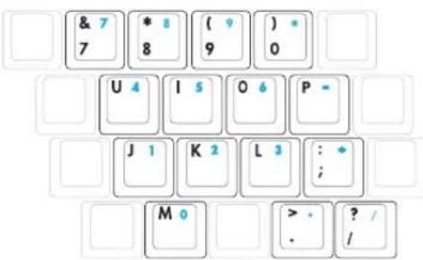
The numeric keypad is embedded in the keyboard and consists of 15 keys that make number intensive input more convenient. These dual-purpose keys are labeled in orange on the key caps. Numeric assignments are located at the upper right hand corner of each key as shown in the figure. When the numeric keypad is engaged by pressing [Fn][Ins/Num LK], the number lock LED lights up. If an external keyboard is connected, pressing the [Ins/Num LK] on the external keyboard enables/disables the NumLock on both keyboards simultaneously. To disable the numeric keypad while keeping the keypad on an external keyboard activated, press the [Fn][Ins/Num LK] keys on the Notebook PC.
text_image
& 7 7 * 8 8 ( 9 ) 9 ) * 0 U 4 I 5 O 6 P - J 1 K 2 L 3 : ; M 0 > . . ? / /Keyboard as Cursors
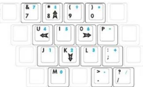
The keyboard can be used as cursors while Number Lock is ON or OFF in order to increase navigation ease while entering numeric data in spreadsheets or similar applications.
With Number Lock OFF, press [Fn] and one of the cursor keys shown below. For example [Fn][8] for up, [Fn][K] for down, [Fn][U] for left, and [Fn][O] for right.
With Number Lock ON, use [Shift] and one of the cursor keys shown below. For example [Shift][8] for up, [Shift][K] for down, [Shift][U] for left, and [Shift][O] for right.
text_image
& 7 7 * 8 8 ( ? 9 ) 0 U 4 ← I 5 O 6 → P - J 1 K 2 ↓ L 3 : + ; M 0 > . . ? / /
NOTE: The arrow symbols are illustrated here for your reference. They are not labeled on the keyboard as shown here.
Switches and Status Indicators
Switches
text_image
Diagram showing a laptop and a toolbar with icons for zoom, edit, lock, set, and rotate functions.InstantON Key
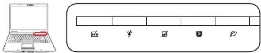
Pressing this key will launch a multimedia player application in Windows. If the Notebook PC is OFF, it will first be turned ON.
Power4 Gear+ Key
The Power4 Gear+ button toggles power savings between various power saving modes. The power saving modes control many aspects of the Notebook PC to maximize performance versus battery time.
When you are using an AC power adapter, Power4 Gear+ will switch between modes in the AC power mode segment. When you remove the AC adapter, Power4 Gear+ will switch between modes in the battery (DC) mode segment. When you remove or apply the AC adapter, Power4 Gear+ will automatically shift you up or down into the proper mode segment (AC or DC).
| Battery Mode AC Mode | |||||||
 |  |  |  |  |  |  | |
 |  |  |  |  |  | ||
Pad-Lock Key
Pressing this button will lock your touchpad when using an external mouse. Locking the touchpad will prevent you from accidentally moving the cursor while typing. To enable the touchpad, simply press this button again.
Splendid Key (on selected models)
Toggles "Splendid" function ON and OFF. This allows switching between different display color enhancement modes in order to improve contrast, brightness, skin tone, and color saturation for red, green, and blue independently. You can see the current mode through the on-screen display (OSD).
| OSD Icons |  |  |  |  |  |  |
Switches (Cont.)
Internet Launch Key
Pressing this button will launch your Internet browser application while Windows is running.
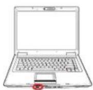
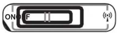
text_image
ON FWireless Switch
Wireless Models Only: Toggles the internal wireless LAN or Bluetooth (on selected models) ON or OFF with an on-screen-display. When enabled, the corresponding wireless indicator will light. Windows software settings are necessary to use the wireless LAN or Bluetooth.
Status Indicators
Above keyboard
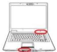
text_image
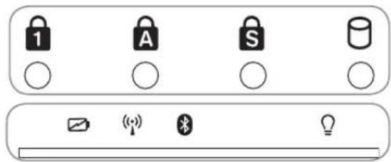
1 A S Battery
Number Lock Indicator
Indicates that number lock [Num Lk] is activated when lighted. Number lock allows some of the keyboard letters to act as numbers for easier numeric data input.

Capital Lock Indicator
Indicates that capital lock [Caps Lock] is activated when lighted. Capital lock allows some of the keyboard letters to type using capitalized letters (e.g. A, B, C). When the capital lock light is OFF, the typed letters will be in the lower case form (e.g. a,b,c).

Scroll Lock Indicator
Indicates that scroll lock [Scr Lk] is activated when lit. Scroll lock allows some of the keyboard letters to act as direction keys in order to allow easier navigation when only a part of the keyboard is required, such as for playing games.

Drive Activity Indicator
Indicates that the Notebook PC is accessing one or more storage device(s) such as the hard disk. The light flashes proportional to the access time.

Battery Charge Indicator
The battery charge indicator is an LED that shows the status of the battery's power as follows:
ON: The Notebook PC's battery is charging when AC power is connected.
OFF: The Notebook PC's battery is charged or completely drained.
Blinking: Battery power is less than 10% and the AC power is not connected.

Wireless Indicator
This is only applicable on models with built-in wireless LAN and/or built-in Bluetooth. When the built-in wireless LAN and/or built-in Bluetooth is enabled, this indicator will light. (Windows software settings are necessary.)

Bluetooth Indicator
This is only applicable on models with internal Bluetooth (BT). This indicator will light to show that the Notebook PC's built-in BT function is activated.

Power Indicator
The power indicator lights when the Notebook PC is turned ON and blinks slowly when the Notebook PC is in the Suspend-to-RAM (Standby) mode. This indicator is OFF when the Notebook PC is turned OFF or in the Suspend-to-Disk (Hibernation) mode.
CD Player Control Buttons & Indicator (on selected models)
There are several CD control buttons integrated externally on the Notebook PC for convenient CD playing. The buttons activate and control your operating system's audio player when the Notebook PC is ON. When your Notebook PC is OFF, the CD control buttons activate a CD player function that allows you to listen to audio CDs even while the Notebook PC is not turned ON. The following defines the meaning of each CD control button and indicator on the front of the Notebook PC.
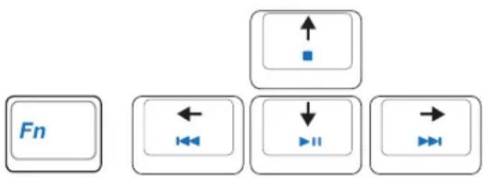
flowchart
graph TD
    A["Fn"] --> B["←"]
    B --> C["↓"]
    C --> D["→"]
Use the [Fn] key in combination with the arrow keys for CD control functions.
CD Play/Pause
During CD stop, begins CD play.
During CD play, pauses CD play.
CD Stop
During CD stop: Ejects the CD tray.
During CD play: Stops CD play.
CD Skip to Previous Track (Rewind) & Audio Volume Down
During CD play, this button has two functions:
Track: The first push will restart the current track. Second push will skip to the previous track.
Audio: Hold down to decrease audio volume.
CD Skip to Next Track (Fast Forward) & Audio Volume Up
During CD play, this button has two functions:
Track: Push once to skip to the next track during CD playing.
Audio: Hold down to increase audio volume.
Audio Volume Controls
Fn + Speaker Icons (F10): Toggles the audio volume ON and OFF
Fn + Down Speaker Icon (F11): Decreases the audio volume
Fn + Up Speaker Icon (F12): Increases the audio volume
3
Getting Started
4. Using the Notebook PC
Operating System
Pointing Device
Storage Devices
ExpressCard Slot
Optical Drive
Hard Disk Drive
Connections
Modem Connection
Network Connection
Wireless LAN Connection
Bluetooth Wireless Connection
Power Management Modes
os Operating System
This Notebook PC may offer (depending on territory) its customers the choice of a pre-installed operating system such as Microsoft Windows XP. The choices and languages will depend on the territory. The levels of hardware and software support may vary depending on the installed operating system. The stability and compatibility of other operating systems cannot be guaranteed.

Support Software
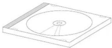
This Notebook PC comes with a support CD that provides BIOS, drivers and applications to enable hardware features, extend functionality, help manage your Notebook PC, or add functionality not provided by the native operating system. If updates or replacement of the support CD is necessary, contact your dealer for web sites to download individual software drivers and utilities.
natural_image
Isometric line drawing of a CD or DVD disc with a central hole and surrounding rectangular base (no text or symbols)The support CD contains all drivers, utilities and software for all popular operating systems including those that have been pre-installed. The support CD does not include the operating system itself. The support CD is necessary even if your Notebook PC came pre-configured in order to provide additional software not included as part of the factory pre-install.
A recovery CD is optional and includes an image of the original operating system installed on the hard drive at the factory. The recovery CD provides a comprehensive recovery solution that quickly restores the Notebook PC's operating system to its original working state provided that your hard disk drive is in good working order. Contact your retailer if you require such a solution.

Note: Some of the Notebook PC's components and features may not work until the device drivers and utilities are installed.

Automatic Touchpad Disabling (on selected models)
Notebook PC models with newer chipsets will automatically disable the Notebook PC's touchpad when an external USB mouse is attached. To turn OFF this feature, deselect the option in Windows Control Panel - Mouse Properties - Device Settings.
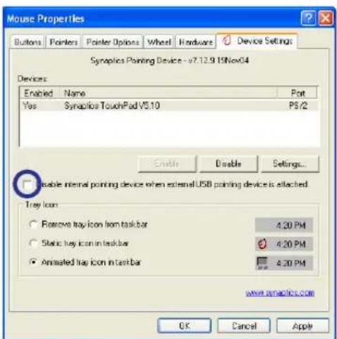
text_image
Mouse Properties Buttons Pointers Pointer Options Wheel Hardware Device Settings Synaptics Pointing Device - v7.12.9.15Nov04 Devices: Enabled Name Port Yes Synaptics TouchPad V5.10 PS/2 Enable Disable Settings... Disable internal pointing device when external USB pointing device is attached. Tray Icon Remove tray icon item taskbar 4.20 PM Static tray icon in taskbar 4.20 PM Animated tray icon in taskbar 4.20 PM www.synaptics.com OK Cancel Apply
Pointing Device
The Notebook PC's integrated touchpad pointing device is fully compatible with all two/three-button and scrolling knob PS/2 mice. The touchpad is pressure sensitive and contains no moving parts; therefore, mechanical failures can be avoided. A device driver is still required for working with some application software.

IMPORTANT! Do not use any objects in place of your finger to operate the touchpad or else damage may occur to the touchpad's surface.
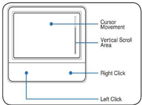
text_image
Cursor Movement Vertical Scroll Area Right Click Left ClickUsing the Touchpad
Light pressure with the tip of your finger is all that is required to operate the touchpad. Because the touchpad is electrostatic sensitive, objects cannot be used in place of your fingers. The touchpad's primary function is to move the cursor around or select items displayed on the screen with the use of your fingertip instead of a standard desktop mouse. The following illustrations demonstrate proper use of the touchpad.
Moving The Cursor
Place your finger in the center of the touchpad and slide in a direction to move the cursor.
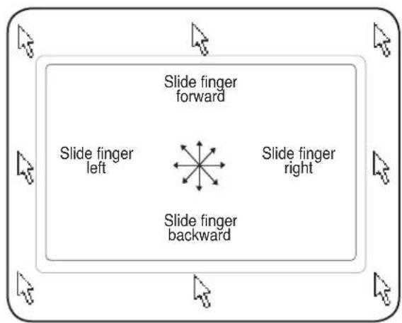
flowchart
graph TD
    A["Slide finger left"] --> B["Slide finger backward"]
    C["Slide finger right"] --> D["Slide finger forward"]
    style A fill:#f9f,stroke:#333
    style B fill:#ccf,stroke:#333
    style C fill:#cfc,stroke:#333
    style D fill:#fcc,stroke:#333
Scrolling (on selected models)
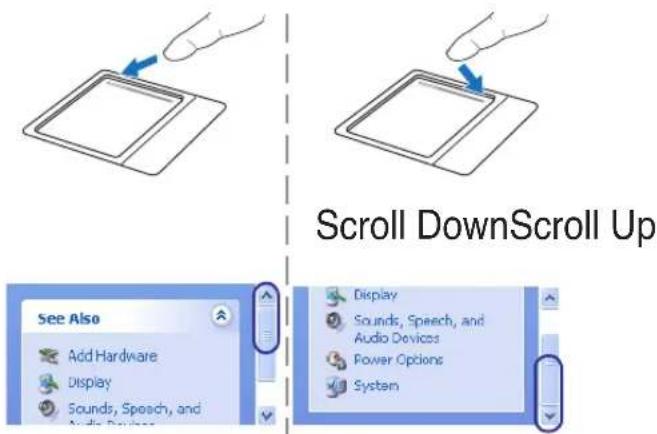
Slide your finger up or down on the right side to scroll a window up or down.
text_image
Scroll DownScroll Up See Also Add Hardware Display Sounds, Speech, and Audio Devices Display Sounds, Speech, and Audio Devices Power Options SystemTouchpad Usage Illustrations
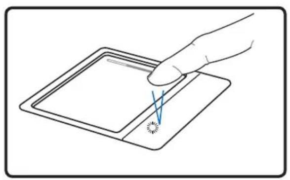
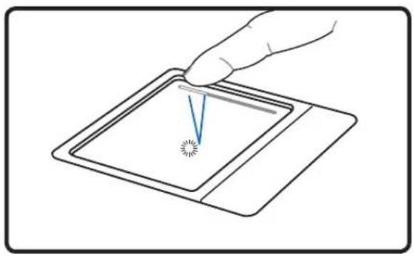
Clicking/Tapping - With the cursor over an item, press the left button or use your fingertip to touch the touchpad lightly, keeping your finger on the touchpad until the item is selected. The selected item will change color. The following 2 examples produce the same results.
natural_image
Illustration of a hand holding a tablet with a pointer and a small starburst mark on the screen (no text or symbols)Clicking Tapping
natural_image
Illustration of a hand holding a tablet with a V-shaped pointer and starburst pattern (no text or symbols)(press the left cursor button and release) (lightly but rapidly strike the touchpad)
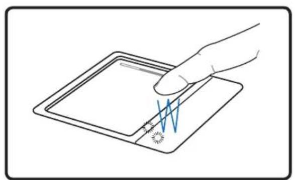
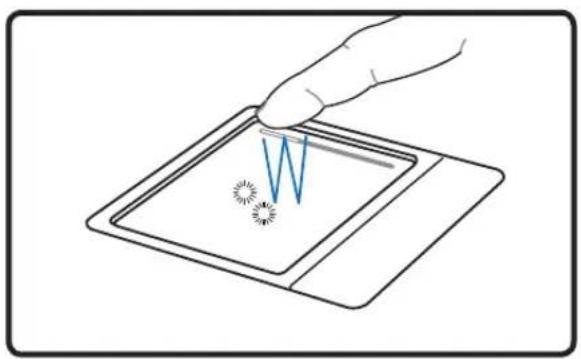
Double-clicking/Double-tapping - This is a common skill for launching a program directly from the corresponding icon you select. Move the cursor over the icon you wish to execute, press the left button or tap the pad twice in rapid succession, and the system launches the corresponding program. If the interval between the clicks or taps is too long, the operation will not be executed. You can set the double-click speed using the Windows Control Panel "Mouse." The following 2 examples produce the same results.
natural_image
Illustration of a hand inserting a W-shaped spring into a rectangular device (no text or symbols)Double-Clicking
natural_image
Illustration of a hand holding a tablet with a compass needle pointing to it, no text or symbols present.Double-Tapping
(press the left button twice and release) (lightly but rapidly strike the touchpad twice)
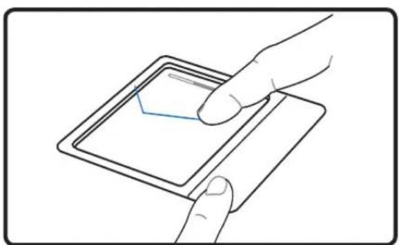
Dragging - Dragging means to pick up an item and place it anywhere on the screen you wish. You can move the cursor over the item you select, and while keeping the left button depressed, moving the cursor to the desired location, then release the button. Or, you can simply double-tap on the item and hold while dragging the item with your fingertip. The following illustrations produce the same results.
natural_image
Line drawing of a hand inserting a card into a tablet device (no text or symbols)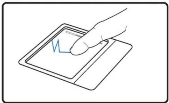
natural_image
Line drawing of a hand pressing a digital tablet with a blue waveform (no text or symbols)Dragging-Clicking Dragging-Tapping
(hold left button and slide finger on touchpad)
(lightly strike the touchpad twice, sliding finger on touchpad during second strike)

NOTE: A software-controlled scrolling function is available after setting up the included touchpad utility to allow easy Windows or web navigation. Basic functions can be adjusted at the Windows control panel to allow comfortable clicking and tapping.
Caring for the Touchpad
The touchpad is pressure sensitive. If not properly cared for, it can be easily damaged. Take note of the following precautions.
- Make sure the touchpad does not come into contact with dirt, liquids or grease.
- Do not touch the touchpad if your fingers are dirty or wet.
- Do not rest heavy objects on the touchpad or the touchpad buttons.
- Do not scratch the touchpad with your finger nails or any hard objects.

NOTE: The touchpad responds to movement not to force. There is no need to tap the surface too hard. Tapping too hard does not increase the responsiveness of the touchpad. The touchpad responds best to light pressure.
Storage Devices
Storage devices allow the Notebook PC to read or write documents, pictures, and other files to various data storage devices. This Notebook PC has the following storage devices:
- ExpressCard
- Optical drive
- Flash memory reader
- Hard disk drive

ExpressCard
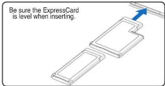
One 26pin Express card slot is available to support one ExpressCard/34mm or on ExpressCard/54mm expansion card. This new interface is faster by using a serial bus supporting USB 2.0 and PCI Express instead of the slower parallel bus used in the PC card slot. (Not compatible with previous PCMCIA cards.)

Inserting an ExpressCard
text_image
Be sure the ExpressCard is level when inserting.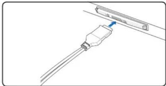
natural_image
Diagram of a cable connector with a blue arrow pointing to the cable (no text or symbols present)-
If there is an ExpressCard socket protector, remove it using the "Removing an ExpressCard" instructions below.
-
Carefully connect any cables or adapters needed by the ExpressCard. Usually connectors can only be inserted in one orientation. Look for a sticker, icon, or marking on one side of the connector representing the top side.
-
Insert the ExpressCard with the connector side first and label side up. Standard ExpressCards will be flush with the Notebook PC when fully inserted.
Removing an ExpressCard
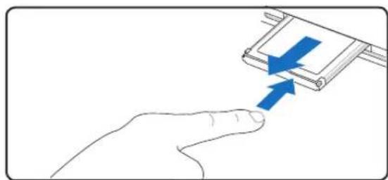
The ExpressCard slot does not have an eject button. Press the ExpressCard inwards and release to eject the ExpressCard. Carefully pull the ejected ExpressCard out of the socket.
natural_image
Hand pressing a button on a mechanical component with blue arrows indicating motion (no text or symbols)Optical Drive Inserting an optical disc
natural_image
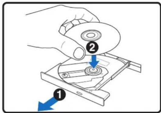
Line drawing of a hand holding a tool with a blue arrow pointing to a small component (no text or symbols)- While the Notebook PC's power is ON, press 2. the drive's eject button and the tray will eject out partially.
text_image
Diagram showing a hand holding a CD drive with labeled parts and directional arrows indicating assembly or disassembly.Gently pull on the drive's front panel and slide the tray completely out. Be careful not to touch the CD drive lens and other mechanisms. Make sure there are no obstructions that may get jammed under the drive's tray.
natural_image
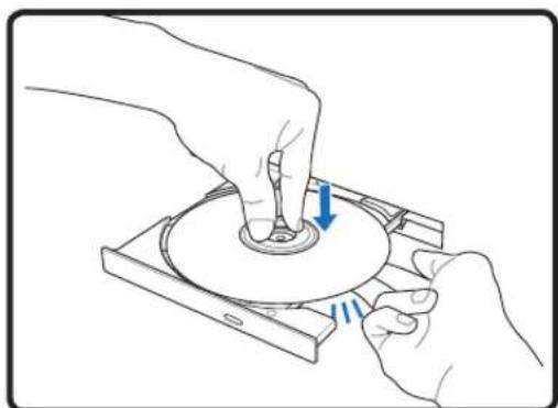
Illustration of hands operating a CD or DVD disc with a blue arrow indicating rotation (no text or symbols present)- Hold the disc by the edge and face the disc's printed side up. Push down on both sides of the disc's center until the disc snaps onto the hub. The hub should be higher than the disc when correctly mounted.
natural_image
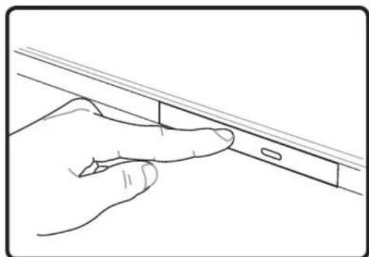
Line drawing of a hand holding a tool near a vertical panel (no text or symbols)- Slowly push the drive's tray back in. The drive will begin reading the table of contents (TOC) on the disc. When the drive stops, the disc is ready to be used.
NOTE: It is normal to hear as well as feel the CD spinning with great intensity in the CD drive while data is read.
Optical Drive (Cont.)
Removing an optical disc
text_image
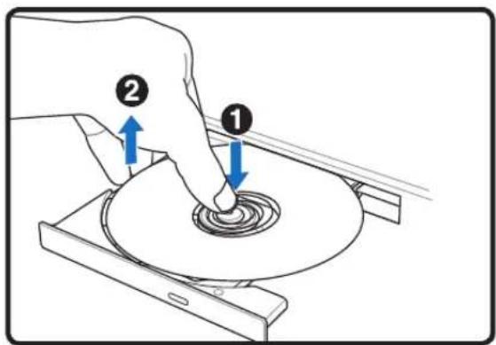
Diagram showing a hand using a tool to press a disc, labeled with arrows indicating process steps 1 and 2.Eject the tray and gently pry the edge of the disc upwards at an angle to remove the disc from the hub.
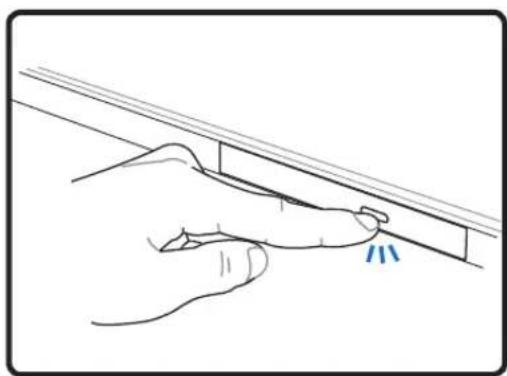
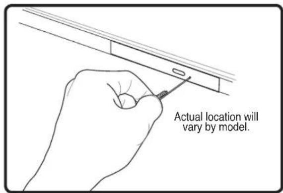
Emergency eject
text_image
Actual location will vary by model.The emergency eject is located in a hole on the optical drive and is used to eject the optical drive tray in case the electronic eject does not work. Do not use the emergency eject in place of the electronic eject. Note: Make sure not to stab the activity indicator located in the same area.
Using the Optical Drive
Optical discs and equipment must be handled with care because of the precise mechanics involved. Keep in mind the important safety instructions from your CD suppliers. Unlike desktop optical drives, the Notebook PC uses a hub to hold the CD in place regardless of the angle. When inserting a CD, it is important that the CD be pressed onto the center hub or else the optical drive tray will scratch the CD.

WARNING! If the CD disc is not properly locked onto the center hub, the CD can be damaged when the tray is closed. Always watch the CD closely while closing the tray slowly to prevent damage.
A CD drive letter should be present regardless of the presence of a CD disc in the drive. After the CD is properly inserted, data can be accessed just like with hard disk drives; except that nothing can be written to or changed on the CD. Using the proper software, a CD-RW drive or DVD+CD-RW drive can allow CD-RW discs to be used like a hard drive with writing, deleting, and editing capabilities.
Vibration is normal for all high-speed optical drives due to unbalanced CDs or CD print. To decrease vibration, use the Notebook PC on an even surface and do not place labels on the CD.
Listening to Audio CD
The optical drives can play audio CDs, but only the DVD-ROM drive can play DVD audio. Insert the audio CD and Windows ^™ automatically opens an audio player and begins playing. Depending on the DVD audio disc and installed software, it may require that you open a DVD player to listen to DVD audio. You can adjust the volume using hotkeys or Windows ^™ speaker icon on the taskbar.

Flash Memory Card Reader
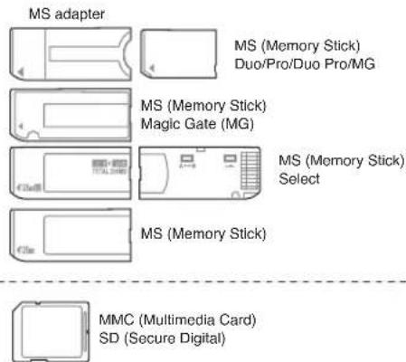
Normally a PCMCIA memory card reader must be purchased separately in order to use memory cards from devices such as digital cameras, MP3 players, mobile phones, and PDAs. This Notebook PC has a single built-in memory card reader that can read the following flash memory cards: Secure Digital (SD), Multi-Media Card (MMC), Memory Stick (MS), Memory Stick Select (MS Select), Memory Stick Duo (with MS adapter), Memory Stick Pro, and Memory Stick Pro Duo (with MS Pro adapter). Memory Sticks may be standard or with MagicGate technology. The built-in memory card reader is not only convenient, but also faster than most other forms of memory card readers because it utilizes the high-bandwidth PCI bus.
Supported Memory Types
text_image
MS adapter MS (Memory Stick) Duo/Pro/Duo Pro/MG MS (Memory Stick) Magic Gate (MG) MS (Memory Stick) Select MS (Memory Stick) MMC (Multimedia Card) SD (Secure Digital)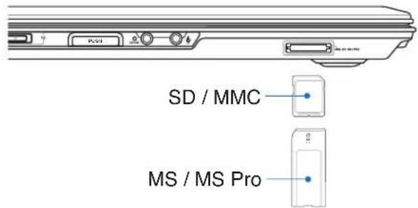
text_image
SD / MMC MS / MS Pro
IMPORTANT! Never remove cards while or immediately after reading, copying, formatting, or deleting data on the card or else data loss may occur.

Hard Disk Drive
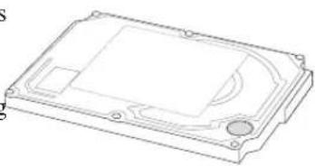
Hard disk drives have higher capacities and operate at much faster speeds than floppy disk drives and optical drives. The Notebook PC comes with a replaceable 2.5" (6.35cm) wide and approximately .374" (.95cm) high hard disk drive. Current hard drives support S.M.A.R.T. (Self Monitoring and Reporting Technology) to detect hard disk errors or failures before they happen. When replacing or upgrading the hard drive, always visit an authorized service center or retailer for this Notebook PC.
natural_image
Technical line drawing of a rectangular electronic device casing with mounting holes and internal compartments (no text or symbols)
IMPORTANT! Poor handling of the Notebook PC may damage the hard disk drive. Handle the Notebook PC gently and keep it away from static electricity and strong vibrations or impact. The hard disk drive is the most delicate component and will likely be the first or only component that is damaged if the Notebook PC is dropped.
4
Using the Notebook PC
Connections

NOTE: The built-in modem and network cannot be installed later as an upgrade. After purchase, modem and/or network can be installed as a PC card (PCMCIA).

Modem Connection
The telephone wire used to connect the Notebook PC's internal modem should have either two or four wires (only two wires (telephone line #1) is used by the modem) and should have an RJ-11 connector on both ends. Connect one end to the modem port and the other end to an analog telephone wall socket (the ones found in residential buildings). Once the driver is setup, the modem is ready to use.
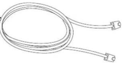
natural_image
Line drawing of a coiled cable with two connectors (no text or symbols)
NOTE: When you are connected to an online service, do not place the Notebook PC in suspend (or sleep mode) or else you will disconnect the modem connection.
Example of the Notebook PC connected to a telephone jack for use with the built-in modem:
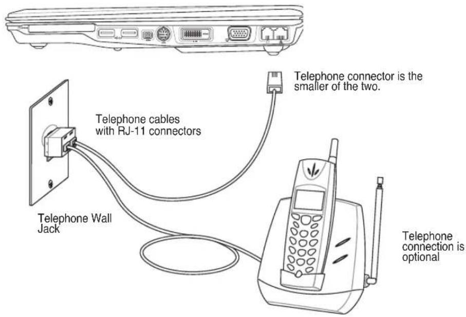
text_image
Telephone wall Jack Telephone cables with RJ-11 connectors Telephone connector is the smaller of the two. Telephone connection is optional
CAUTION: For electrical safety concerns, only use telephone cables rated 26AWG or higher. (see Glossary for more information)

Network Connection
Connect a network cable, with RJ-45 connectors on each end, to the modem/network port on the Notebook PC and the other end to a hub or switch. For 100 BASE-TX / 1000 BASE-T speeds, your network cable must be category 5 or better (not category 3) with twisted-pair wiring. If you plan on running the interface at 100/1000Mbps, it must be connected to a 100 BASE-TX / 1000 BASE-T hub (not a BASE-T4 hub). For 10Base-T, use category 3, 4, or 5 twisted-pair wiring. 10/100 Mbps Full-Duplex is supported on this Notebook PC but requires connection to a network switching hub with “duplex” enabled. The software default is to use the fastest setting so no user-intervention is required.

1000BASE-T (or Gigabit) is only supported on selected models.
Twisted-Pair Cable
The cable used to connect the Ethernet card to a host (generally a Hub or Switch) is called a straight-through Twisted Pair Ethernet (TPE). The end connectors are called RJ-45 connectors, which are not compatible with RJ-11 telephone connectors. If connecting two computers together without a hub in between, a crossover LAN cable is required (Fast-Ethernet model). (Gigabit models support auto-crossover so a crossover LAN cable is optional.)
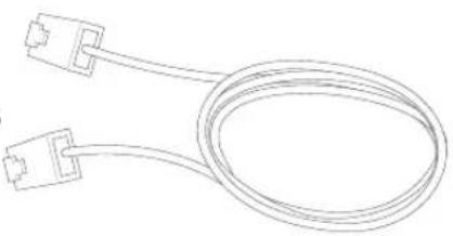
natural_image
Line drawing of a flexible cable with two connectors (no text or symbols)Example of the Notebook PC connected to a Network Hub or Switch for use with the built-in Ethernet controller.
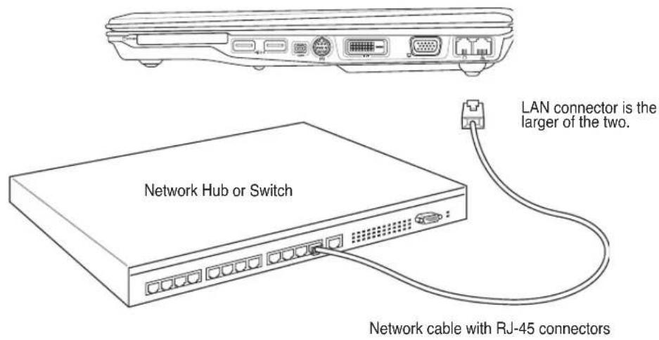
text_image
Network Hub or Switch LAN connector is the larger of the two. Network cable with RJ-45 connectors
WARNING! Only use analog telephone outlets. The built-in modem does not support the voltage used in digital phone systems. Do not connect the RJ-11 to digital phone systems found in many commercial buildings or else damage will occur!
(☐) Wireless LAN Connection (on selected models)
The optional built-in wireless LAN is a compact easy-to-use wireless Ethernet adapter. Implementing the IEEE 802.11 standard for wireless LAN (WLAN), the optional built-in wireless LAN is capable of fast data transmission rates using Direct Sequence Spread Spectrum (DSSS) and Orthogonal Frequency Division Multiplexing (OFDM) technologies on 2.4GHz/5GHz frequencies. The optional built-in wireless LAN is backward compatible with the earlier IEEE 802.11 standards allowing seamless interfacing of wireless LAN standards.
The optional built-in wireless LAN is a client adapter that supports Infrastructure and Ad-hoc modes giving you flexibility on your existing or future wireless network configurations for distances up to 40 meters between the client and the access point.
To provide efficient security to your wireless communication, the optional built-in wireless LAN comes with a 64-bit/128-bit Wired Equivalent Privacy (WEP) encryption and Wi-Fi Protected Access (WPA) features.
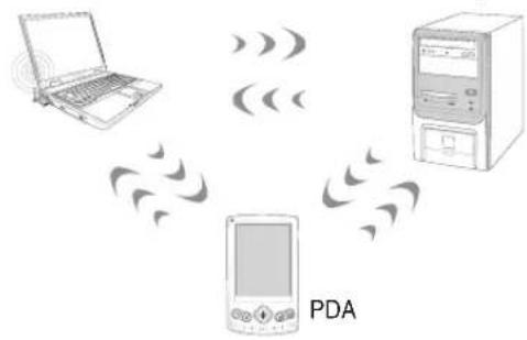
Ad-hoc mode
The Ad-hoc mode allows the Notebook PC to connect to another wireless device. No access point (AP) is required in this wireless environment.
(All devices must install optional 802.11 wireless LAN adapters.)
These are examples of the Notebook PC connected to a Wireless Network.
Notebook PC
text_image
PDADesktop PC
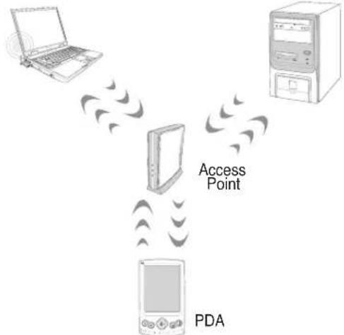
Infrastructure mode
The Infrastructure mode allows the Notebook PC and other wireless devices to join a wireless network created by an Access Point (AP) (sold separately) that provides a central link for wireless clients to communicate with each other or with a wired network.
(All devices must install optional 802.11 wireless LAN adapters.)
Notebook PC
flowchart
graph TD
    A["Laptop"] --> B["Access Point"]
    C["Server"] --> B
    D["PDA"] --> B
    B --> E["Return to Laptop"]
    style B fill:#f9f,stroke:#333
Desktop PC
Bluetooth Wireless Connection (on selected models)
Notebook PCs with Bluetooth technology eliminates the need for cables for connecting Bluetooth-enabled devices. Examples of Bluetooth-enabled devices may be Notebook PCs, Desktop PCs, mobile phones, and PDAs.
Note: If your Notebook PC did not come with built-in Bluetooth, you need to connect a USB or ExpressCard Bluetooth module in order to use Bluetooth.
Bluetooth-enabled mobile phones
You can wireless connect to your mobile phone. Depending on your mobile phone's capabilities, you can transfer phone book data, photos, sound files, etc. or use it as a modem to connect to the Internet. You may also use it for SMS messaging.
Bluetooth-enabled computers or PDAs
You can wireless connect to another computer or PDA and exchange files, share peripherals, or share Internet or network connections. You may also make use of Bluetooth-enabled wireless keyboard or mouse.
Pairing with Bluetooth-enabled devices
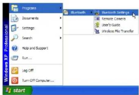
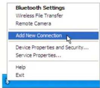
You first need to pair your Notebook PC with a Bluetooth-enabled device before you can connect to it. Make sure the Bluetooth-enabled device is turned ON and ready to accept a pair. Launch Bluetooth Settings from Windows Start | Programs | Bluetooth or select Add New Connection from the Bluetooth taskbar icon if available.

Bluetooth Information Exchanger
text_image
Programs Documents Settings Search Help and Support Run... Log Off Turn Off Computer... Bluetooth Settings Remote Camera User's Guide Wireless File Transfer startBluetooth Settings from Windows Start I Programs I Bluetooth
text_image
Bluetooth Settings Wireless File Transfer Remote Camera Add New Connection Device Properties and Security... Service Properties... Help ExitAdd New Connection from the Bluetooth taskbar icon
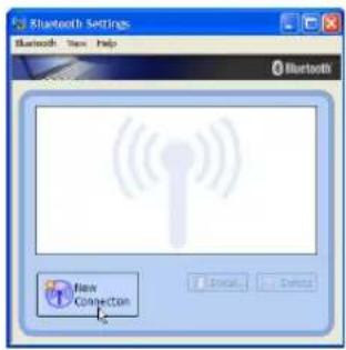
text_image
Bluetooth Settings Bluetooth: New Help Bluetooth Flow CONNECTION OK Cancel NextClick New Connection from Bluetooth Settings.
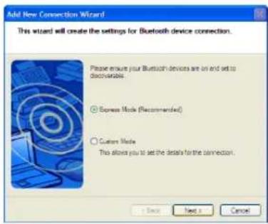
text_image
Add New Connection Wizard This wizard will create the settings for Bluetooth device connection. Please ensure your Bluetooth devices are on and set to discoverable. ◎ Bower Mode (Recommended) ○ Custom Mode This allows you to set the details for the connection. → Back Next > CancelFollow the wizard to add Bluetooth devices.
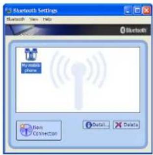
text_image
Bluetooth Settings Bluetooth View Help My wireless phone New CONNECTION Detail DeleteAfter complete, you should see your device in the window.

Trusted Platform Module (TPM) (on selected models)
The TPM, or Trusted Platform Module, is a security hardware device on the system board that will hold computer-generated keys for encryption. It is a hardware-based solution that an help avoid attacks by hackers looking to capture passwords and encryption keys to sensitive data. The TPM provides the ability to the PC or notebook to run applications more secure and to make transactions and communication more trustworthy.
The security features provided by the TPM are internally supported by the following cryptographic capabilities of each TPM: hashing, random number generation, asymmetric key generation, and asymmetric encryption/decryption. Each individual TPM on each individual computer system has a unique signature initialized during the silicon manufacturing process that further enhances its trust/security effectiveness. Each individual TPM must have an Owner before it is useful as a security device.
TPM Applications
TPM is useful for any customer that is interested in providing an addition layer of security to the computer system. The TPM, when bundled with an optional security software package, can provide overall system security, file protection capabilities and protect against email/privacy concerns. TPM helps provide security that can be stronger than that contained in the system BIOS, operating system, or any non-TPM application.

Note: The TPM is disabled by default. Use BIOS setup to enable it.

Important: Use your TPM application's "Restore" or "Migration" function to backup your TPM security data.
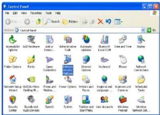
text_image
Control Panel File Edit View Favorites Tools Help Search Folders Address Control Panel Accessibility Options Add Hardware Add or Remove... Administrative Tools Automatic Updates Bluetooth Local COM Date and Time Display Folder Options Fonts Case Controllers EFSOOS Security Platforms Internet Options Keyboard Places Network Connections Network Setup Wizard MASCIA New Desktop PC Phone and Modem Power Options Printers and Faces Regional and Language Scanners and Camera S Scheduled Tasks Security Center Sounds and Audio Devices Speech System Taskbox and StartMenu User Accounts Windows Firewall Wireless Network Job...You can launch the Security Platform application from Windows "Control Panel".
text_image
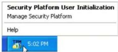
Security Platform User Initialization Manage Security Platform Help 5:02 PMWhen the Security Platform is running, this icon will show in the Windows taskbar. You can choose to initialize or manage here.
text_image
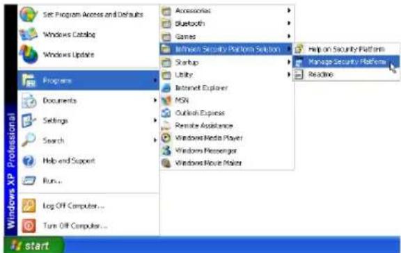
Set Program Access and Defaults Windows Catalog Windows Update Programs Documents Settings Search Help and Support Run... Log OFF Computer... Turn Off Computer... Accessories Bluetooth Games Influx Security Platform Solution Startup Utility Internet Explorer MSN Outlook Express Remote Assistance Windows Media Player Windows Messenger Windows Mouse Maker Help on Security Platform Manage Security Platform Ready startYou can launch the Security Platform application from Windows "Start" menu.
text_image
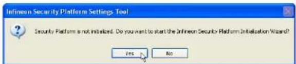
Infineon Security Platform Settings Tool Security Platform is not initialized. Do you want to start the Infineon Security Platform Implementation Wizard? Yes NoWhen you launch the Security Platform application for the first time, answer Yes and follow the instructions to configure it.
Power Management Modes
The Notebook PC has a number of automatic or adjustable power saving features that you can use to maximize battery life and lower Total Cost of Ownership (TCO). You can control some of these features through the Power menu in the BIOS Setup. ACPI power management settings are made through the operating system. The power management features are designed to save as much electricity as possible by putting components into a low power consumption mode as often as possible but also allow full operation on demand. These low power modes are referred to as “Stand by” (or Suspend-to-RAM) and “Hibernation” mode or Suspend-to-Disk (STD). The Standby mode is a simple function provided by the operating system. When the Notebook PC is in either one of the power saving modes, the status will be shown by the following: “Stand by”: Power LED Blinks and “Hibernation”: Power LED OFF.
Full Power Mode & Maximum Performance
The Notebook PC operates in Full Power mode when the power management function is disabled by configuring Windows power management and SpeedStep. When the Notebook PC is operating in Full Power Mode, the Power LED remains ON. If you are conscious of both system performance and power consumption, select “Maximum Performance” instead of disabling all power management features.
ACPI
Advanced Configuration and Power Management (ACPI) was developed by Intel, Microsoft, and Toshiba especially for Windows and later to control power management and Plug and Play features. ACPI is the new standard in power management for Notebook PCs.
NOTE: APM was used in older operating systems like Windows NT4 and Windows 98. Because newer operating systems like Windows XP, Windows 2000, and Windows ME utilize ACPI, APM is no longer fully supported on this Notebook PC.
Suspend Mode
In “Stand by” (STR) and “Hibernation” (STD), the CPU clock is stopped and most of the Notebook PC devices are put in their lowest active state. The suspend mode is the lowest power state of the Notebook PC. The Notebook PC enters suspend mode when the system remains idle for a specified amount of time or manually using the [Fn][F1] keys. The Power LED blinks when the Notebook PC is in STR mode. In STD mode, the Notebook PC will appear to be powered OFF. Recover from STR by pressing any keyboard button (except Fn). Recover from STD by using the power switch (just like powering ON the Notebook PC).
Power Savings
In addition to reducing the CPU clock, this mode puts devices including the LCD backlight in their lower active state. The Notebook PC enters “Stand by” mode (low priority) when the system remains idle for a specified amount of time. The time-out can be set through Windows power management (higher priority). To resume system operation, press any key.

Power State Summary
| STATE ENTRY EVENT | ENT EXIT EVENT | |
| “Stand by” | • “Stand by” through Windows Start button• Timer as set though “Power Management” in Windows Control Panel (higher priority) | • Any device• Battery low |
| STR (“Stand by”) (Suspend-to-RAM) | • Hotkey (see “Colored Hotkeys” under “Special Keyboard Functions” in the previous section) | • Signal from modem port• Power button or any key |
| STD (“Hibernate”) (Suspend-to-Disk) | • Hotkey (see “Colored Hotkeys” under “Special Keyboard Functions” in the previous section) | • Power button |
| Soft OFF | • Power button (can be defined as STR or STD)• “Shut down” through Windows Start button | • Power button |

Thermal Power Control
There are three power control methods for controlling the Notebook PC's thermal state. These power control cannot be configured by the user and should be known in case the Notebook PC should enter these states. The following temperatures represent the chassis temperature (not CPU).
- The fan turns ON for active cooling when the temperature reaches the safe upper limit.
- The CPU decreases speed for passive cooling when the temperature exceeds the safe upper limit.
- The system shut down for critical cooling when temperature exceeds the maximum safe upper limit.
Stand by and Hibernate
Power management settings can be found in the Windows control panel. The following shows the power options properties in Windows. You can define “Stand By” or “Shut down” for closing the display panel, pressing the power button, or activating sleep mode. “Stand by” and “Hibernate” saves power when your Notebook PC is not in use by turning OFF certain components. When you resume your work, your last status (such as a document scrolled down half way or email typed half way) will reappear as if you never left. “Shut down” will close all applications and ask if you want to save your work if any are not saved.
“Stand by” is the same as Suspend-to-RAM (STR). This function stores your current data and status in RAM while many components are turned OFF. Because RAM is volatile, it requires power to keep (refresh) the data. To operate: select “Start” | “Shut down”, and “Stand by”.

Shut Down...

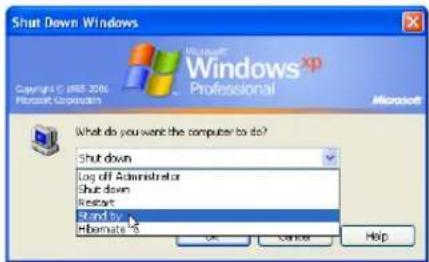
text_image
Shut Down Windows Copyright © 2006 Microsoft Corporation Microsoft® Windows XP Professional Microsoft What do you want the computer to do? Shut down Log off Administrator Shut down Restart Stand by: Hemate's OK Cancel Help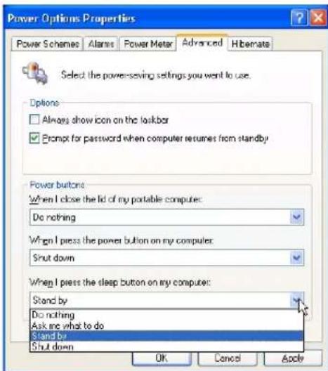
text_image
Power Options Properties Power Schemes Alarms Power Meter Advanced Hibernate Select the power-saving settings you want to use. Options □ Always show icon on the taskbar ✓ Prompt for password when computer resumes from standby Power buttons When I close the lid of my portable computer: Do nothing When I press the power button on my computer: Shut down When I press the sleep button on my computer: Stand by Do nothing Ask me what to do Stand by Shut down OK Cancel Apply“Hibernate” is the same as Suspend-to-Disk (STD) and stores your current data and status on the hard disk drive. By doing this, RAM does not have to be periodically refreshed and power consumption is greatly reduced but not completely eliminated because certain wake-up components like LAN needs to remain powered. “Hibernate” saves more power compared to “Stand by”. To operate: Enable hibernation in “Power Options” and select “Start” | “Shut down”, and “Hibernate”.

Shut Down...

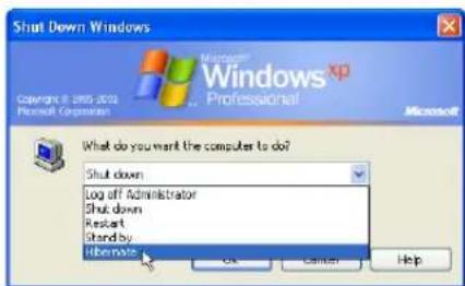
text_image
Shut Down Windows Microsoft Windows XP Professional Copyright © 2005-2010 Microsoft Corporation Microsoft What do you want the computer to do? Shut down Log off Administrator Shut down Restart Standby: Hibernate OK Cancel Help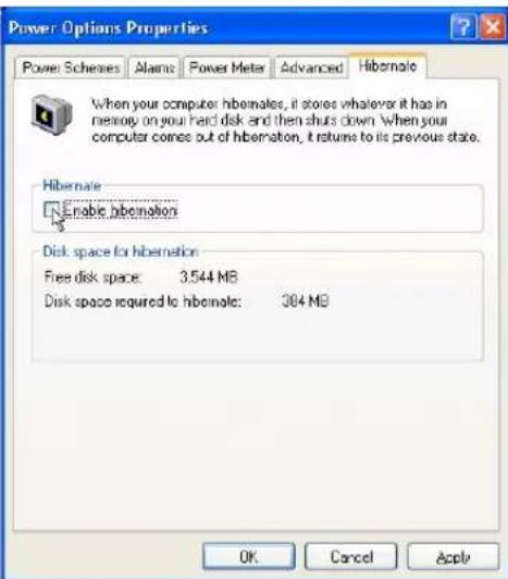
text_image
Power Options Properties Power Schemes Alarms Power Meter Advanced Hibernate When your computer hibernates, it stores whatever it has in memory on your hard disk and then shuts down. When your computer comes out of hibernation, it returns to its previous state. Hibernate Enable hibernation Disk space for hibernation Free disk space: 3.544 MB Disk space required to hibernate: 384 MB OK Cancel Apply4
Using the Notebook PC
Appendix
Optional Accessories
Optional Connections
Glossary
Declarations and Safety Statements
Notebook PC Information
Optional Accessories
These items, if desired, come as optional items to complement your Notebook PC.

USB Hub (Optional) 2.0
Attaching an optional USB hub will increase your USB ports and allow you to quickly connect or disconnect many USB peripherals through a single cable.
natural_image
3D rendering of a rectangular electronic device with multiple ports and mounting holes (no text or symbols visible)
USB Keyboard and Mouse

Attaching an external USB keyboard will allow data entry to be more comfortable. Attaching an external USB mouse will allow Windows navigation to be more comfortable. Both the external USB keyboard and mouse will work simultaneously with the Notebook PC's built-in keyboard and touchpad.
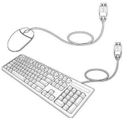
natural_image
Line drawing of a computer keyboard connected to a mouse via cable (no text or symbols)
USB Flash Memory Disk

A USB flash memory disk is an optional item that can replace the 1.44MB floppy disk and provide storage up to several hundred megabytes, higher transfer speeds, and greater durability. When used in current operating systems, no drivers are necessary.
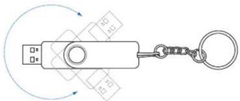
natural_image
Diagram of a keychain with USB port and circular connector, no text or symbols present
USB Floppy Disk Drive
An optional USB-interface floppy disk drive can accept a standard 1.44MB (or 720KB) 3.5-inch floppy diskette.
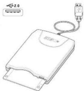
natural_image
Line drawing of a USB flash drive with connector and cable (no text or symbols)
WARNING! To prevent system failures, use (Safely Remove Hardware) on the taskbar before disconnecting the USB floppy disk drive. Eject the floppy disk before transporting the Notebook PC to prevent damage from shock.
Optional Connections
These items, if desired, may be purchased from third-parties.
Printer Connection

One or more USB printers can be simultaneously used on any USB port or USB hub.
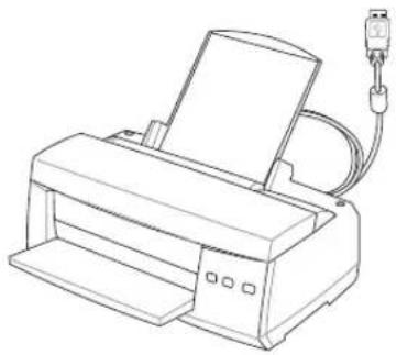
natural_image
Line drawing of a printer with paper feed and cable (no text or symbols)Bluetooth mouse (optional)
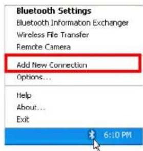
text_image
Bluetooth Settings Bluetooth Information Exchanger Wireless File Transfer Remote Camera Add New Connection Options... Help About... Exit 6:10 PM- A Bluetooth icon should be located on your Windows taskbar. Right click the taskbar Bluetooth icon and ch oo se Ad d New Connection.
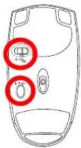
text_image
Diagram of a car door with red circular annotations highlighting specific parts, including '###' and '###'.-
Turn ON the switch on the bottom of the mouse.
-
Push the "RESET" button on the bottom of the mouse.
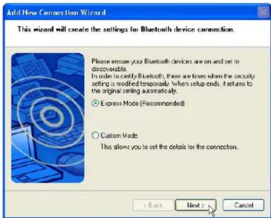
text_image
Add New Connection Wizard This wizard will create the settings for Bluetooth device connection. Please ensure your Bluetooth devices are on and set to discoverable. In order to certify Bluetooth, there are times when the security setting is modified temporarily. When setup ends, it returns to the original setting automatically. ○ Express Mode (Recommended) ○ Custom Mode This allows you to set the details for the connection. < Back Next > Cancel- Select "Express Mode" and click Next.
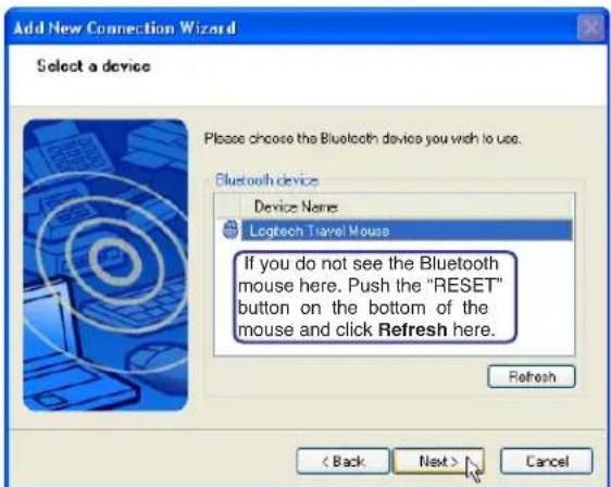
text_image
Add New Connection Wizard Select a device Please choose the Bluetooth device you wish to use. Bluetooth device Device Name Logitech Travel Mouse If you do not see the Bluetooth mouse here. Push the "RESET" button on the bottom of the mouse and click Refresh here. Refresh < Back Next > Cancel- A list of available Bluetooth devices will appear. Select "Logitech Travel Mouse" and click Next.
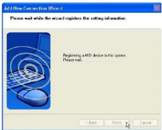
text_image
Add New Connection Wizard Please wait while the wizard registers the setting information. Registering a HiD device to this system. Please wait. < Back Finish Cancel- The software will register the Bluetooth mouse. Click Finish when complete.
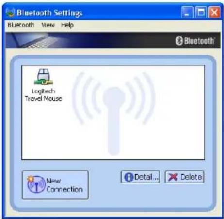
text_image
Bluetooth Settings Bluetooth View Help Logitech Travel Mouse New Connection Detail... Delete- A mouse icon with a pair of green and yellow hands will show in this window.

Note: "RESET" may be necessary after changing batteries. Repeat steps if necessary.
Troubleshooting
Question: How do I check if my Bluetooth is ready?
In "Device Manager", check if "Bluetooth Personal Area Network" is available as shown here.
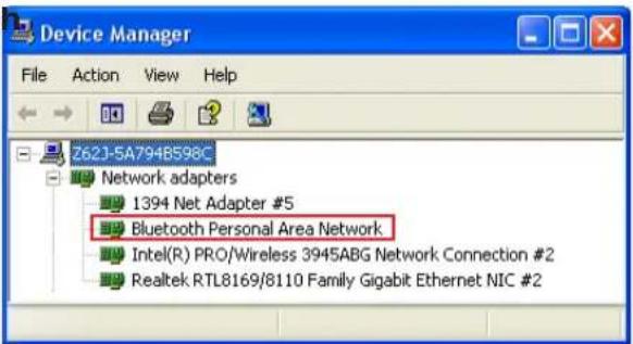
text_image
Device Manager File Action View Help Z621-5A7948598C Network adapters 1394 Net Adapter #5 Bluetooth Personal Area Network Intel(R) PRO/Wireless 3945ABG Network Connection #2 Realtek RTL8169/8110 Family Gigabit Ethernet NIC #2Question: I cannot see my Bluetooth mouse in the list. What do I do?
Click Refresh in the software and "RESET" on the mouse. Repeat if necessary.
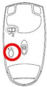
text_image
Diagram of a mobile phone rear panel with labeled buttons and a red circle highlighting the button.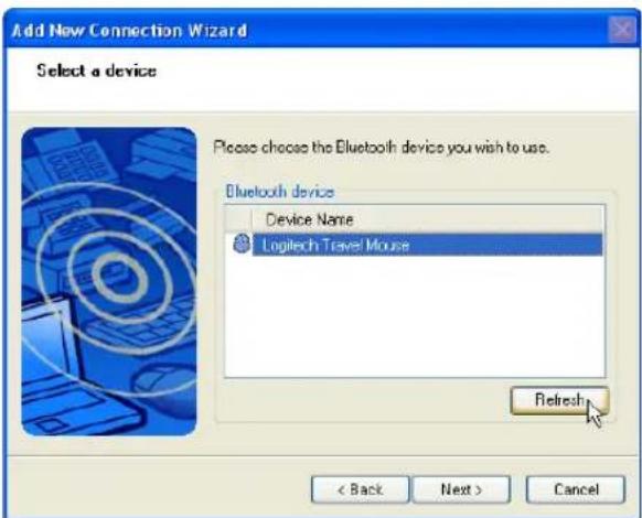
text_image
Add New Connection Wizard Select a device Please choose the Bluetooth device you wish to use. Bluetooth device Device Name Logitech Travel Mouse Refresh < Back Next > CancelQuestion: I already registered the Bluetooth mouse before. Why is it not working now? How do I connect to it?
Double-click on the Bluetooth Icon.
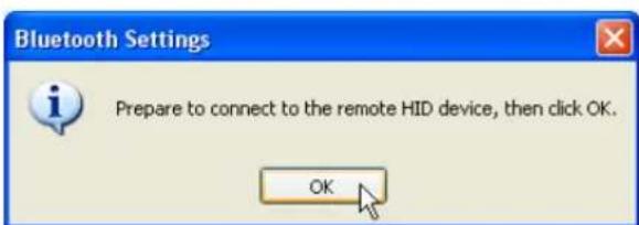
text_image
Bluetooth Settings Prepare to connect to the remote HID device, then click OK. OKA prompt will appear for confirmation. Click OK.
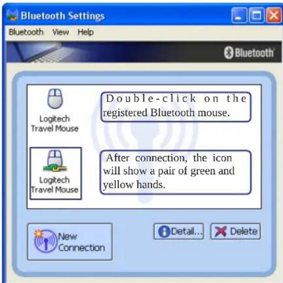
text_image
Bluetooth Settings Bluetooth View Help Logitech Travel Mouse Double-click on the registered Bluetooth mouse. Logitech Travel Mouse After connection, the icon will show a pair of green and yellow hands. New Connection Detail... DeleteGlossary
ACPI (Advanced Configuration and Power Management Interface)
Modern standard for reducing power usage in computers.
APM (Advanced Power Management)
Modern standard for reducing power usage in computers.
AWG (American Wire Gauge)

NOTE: This table is for general reference only and should not be used as a source of the American Wire Gauge standard as this table may not be current or complete.
| Gauge Diam Area R I@3A/mm2AWG (mm) (mm2) (ohm/km) (mA) | Gauge Diam Area R I@3A/mm2AWG (mm) (mm2) (ohm/km) (mA) |
| 33 0.18 0.026 676 75 | 24 0.50 0.20 87.5 588 |
| 0.19 0.028 605 85 | 0.55 0.24 72.3 715 |
| 32 0.20 0.031 547 93 | 0.60 0.28 60.7 850 |
| 30 0.25 0.049 351 147 | 22 0.65 0.33 51.7 1.0 A |
| 29 0.30 0.071 243 212 | 0.70 0.39 44.6 1.16 A |
| 27 0.35 0.096 178 288 | 0.75 0.44 38.9 1.32 A |
| 26 0.40 0.13 137 378 | 20 0.80 0.50 34.1 1.51 A |
| 25 0.45 0.16 108 477 | 0.85 0.57 30.2 1.70 A |
BIOS (Basic Input/Output System)
BIOS is a set of routines that affect how the computer transfers data between computer components, such as memory, disks, and the display adapter. The BIOS instructions are built into the computer's read-only memory. BIOS parameters can be configured by the user through the BIOS Setup program. The BIOS can be updated using the provided utility to copy a new BIOS file into the EEPROM.
Bit (Binary Digit)
Represents the smallest unit of data used by the computer. A bit can have one of two values: 0 or 1.
Boot
Boot means to start the computer operating system by loading it into system memory. When the manual instructs you to “boot” your system (or computer), it means to turn ON your computer. “Reboot” means to restart your computer. When using Windows 95 or later, selecting “Restart” from “Start | Shut Down...” will reboot your computer.
Bluetooth (on selected models)
Bluetooth is a short-range wireless technology that lets you connect computers, mobile phones, and handheld devices to each other and to the Internet. Bluetooth technology eliminates the need for the cables that connect devices together. Bluetooth-enabled devices connect wirelessly within a 10 m range.
Byte (Binary Term)
One byte is a group of eight contiguous bits. A byte is used to represent a single alphanumeric character, punctuation mark, or other symbol.
Clock Throttling
Chipset function which allows the processor's clock to be stopped and started at a known duty cycle. Clock throttling is used for power savings, thermal management, and reducing processing speed.
CPU (Central Processing Unit)
The CPU, sometimes called “Processor,” actually functions as the “brain” of the computer. It interprets and executes program commands and processes data stored in memory.
Device Driver
A device driver is a special set of instructions that allows the computer's operating system to communicate with devices such as VGA, audio, Ethernet, printer, or modem.
DVD
DVD is essentially a bigger, faster CD that can hold video as well as audio and computer data. With these capacities and access rates, DVD discs can provide you with dramatically-enhanced high-color, full-motion videos, better graphics, sharper pictures, and digital audio for a theater-like experience. DVD aims to encompass home entertainment, computers, and business information with a single digital format, eventually replacing audio CD, videotape, laserdisc, CD-ROM, and video game cartridges.
ExpressCard
ExpressCard slot is 26 pins and support one ExpressCard/34mm or one ExpressCard/54mm expansion card. This new interface is faster by using a serial bus supporting USB 2.0 and PCI Express instead of the slower parallel bus used in the PC card slot. (Not compatible with previous PCMCIA cards.)
Hardware
Hardware is a general term referring to the physical components of a computer system, including peripherals such as printers, modems, and pointing devices.
IDE (Integrated Drive Electronics)
IDE devices integrate the drive control circuitry directly on the drive itself, eliminating the need for a separate adapter card (in the case for SCSI devices). UltraDMA/66 or 100 IDE devices can achieve up to 33MB/Sec transfer.
IEEE1394 (1394)
Also known as iLINK (Sony) or FireWire (Apple). 1394 is a high speed serial bus like SCSI but has simple connections and hot-plugging capabilities like USB. The popular 1394a interface has a bandwidth of 400Mbits/sec and can handle up to 63 units on the same bus. The newer 1394b interface can support twice the speed and will appear in future models when peripherals support higher speeds. It is very likely that 1394, together with USB, will replace Parallel, IDE, SCSI, and EIDE ports. 1394 is also used in high-end digital equipment and should be marked “DV” for Digital Video port.
Infrared Port (IrDA) (on selected models)
The infrared (IrDA) communication port allows convenient wireless data communication with infrared-equipped devices or computers up to 4Mbits/sec. This allows easy wireless synchronization with PDAs or mobile phones and even wireless printing to printers. Small offices can use IrDA technology to share a printer between several closely placed Notebook PCs and even send files to each other without a network.
Kensington ^® Locks
Kensington ^® locks (or compatible) allow the Notebook PC to be secured usually using a metal cable and lock that prevent the Notebook PC to be removed from a fixed object. Some security products may also include a motion detector to sound an alarm when moved.
Laser Classifications
As lasers became more numerous and more widely used, the need to warn users of laser hazards became apparent. To meet this need, laser classifications were established. Current classification levels vary from optically safe, requiring no controls (Class 1) to very hazardous, requiring strict controls (Class 4).
CLASS 1: A Class 1 laser or laser system emits levels of optical energy that are eye-safe and consequently require no controls. An example of this class of laser system is the checkout scanning device found in most grocery stores or lasers used in optical drives.
CLASS 2 & CLASS 3A: Class 2 and Class 3A lasers emit visible, continuous-wave (CW) optical radiation levels slightly above the maximum permissible exposure (MPE) level. Although these lasers can cause eye damage, their brightness usually causes observers to look away or blink before eye damage occurs. These lasers have strict administrative controls requiring placement of signs warning personnel not to stare directly into the beam. Class 3A lasers must not be viewed with optically-aided devices.
CLASS 3B: Class 3B lasers, and Class 3A lasers with outputs of 2.5mW, are hazardous to personnel who are within the beam path and look at the beam source directly or by specular reflection. These lasers cannot produce hazardous diffuse reflections. Personnel working with these lasers should wear appropriate protective eyewear during any operation of the laser. Class 3B lasers have both administrative and physical controls to protect personnel. Physical controls include limited access work areas. Administrative controls include special warning signs posted outside the entrances to the laser work spaces and lights outside the entrances that warn personnel when the lasers are in use.
CLASS 4: Class 4 lasers are high-power lasers that will cause damage to unprotected eyes and skin through intra-beam viewing and specular or diffuse reflections. Consequently, no personnel should be in a room where a Class 4 laser is operating without proper eye protection.
PCI Bus (Peripheral Component Interconnect Local Bus)
PCI bus is a specification that defines a 32-bit data bus interface. PCI is a standard widely used by expansion card manufacturers.
POST (Power On Self Test)
When you turn on the computer, it will first run through the POST, a series of software-controlled diagnostic tests. The POST checks system memory, the motherboard circuitry, the display, the keyboard, the diskette drive, and other I/O devices.
RAM (Random Access Memory)
RAM (usually just called memory) is the place in a computer where the operating system, application programs, and data in current use are temporarily kept so that they can be quickly reached by the computer's processor instead of having to read from and write to slower storage such as the hard disk or optical disc.
Suspend Mode
In Save-to-RAM (STR) and Save-to-Disk (STD), the CPU clock is stopped and most of the Notebook PC devices are put in their lowest active state. The Notebook PC enters Suspend when the system remains idle for a specified amount of time or manually using the function keys. The time-out setting of both Hard Disk and Video can be set by the BIOS Setup. The Power LED blinks when the Notebook PC is in STR mode. In STD mode, the Notebook PC will appear to be powered OFF.
System Disk
A system disk contains the core file of an operating system and is used to boot up the operating system.
TPM (Trusted Platform Module) (on selected models)
The TPM is a security hardware device on the system board that will hold computer-generated keys for encryption. It is a hardware-based solution that can help avoid attacks by hackers looking to capture passwords and encryption keys to sensitive data. The TPM provides the ability to the PC or Notebook PC to run applications more secure and to make transactions and communication more trustworthy.
Twisted-Pair Cable
The cable used to connect the Ethernet card to a host (generally a Hub or Switch) is called a straight-through Twisted Pair Ethernet (TPE). The end connectors are called RJ-45 connectors, which are not compatible with RJ-11 telephone connectors. If connecting two computers together without a hub in between, a crossover twisted-pair is required.
UltraDMA/66 or 100
UltraDMA/66 or 100 are new specifications to improve IDE transfer rates. Unlike traditional PIO mode, which only uses the rising edge of IDE command signal to transfer data, UltraDMA/66 or 100 uses both rising edge and falling edge.
USB (Universal Serial Bus)
A new 4-pin serial peripheral bus that allows plug and play computer peripherals such as keyboard, mouse, joystick, scanner, printer and modem/ISDN to be automatically configured when they are attached physically without having to install drivers or reboot. With USB, the traditional complex cables from back panel of your PC can be eliminated.
Declarations and Safety Statements

DVD-ROM Drive Information
The Notebook PC comes with an optional DVD-ROM drive or a CD-ROM drive. In order to view DVD titles, you must install your own DVD viewer software. Optional DVD viewer software may be purchased with this Notebook PC. The DVD-ROM drive allows the use of both CD and DVD discs.
Regional Playback Information
Playback of DVD movie titles involves decoding MPEG2 video, digital AC3 audio and decryption of CSS protected content. CSS (sometimes called copy guard) is the name given to the content protection scheme adopted by the motion picture industry to satisfy a need to protect against unlawful content duplication.
Although the design rules imposed on CSS licensors are many, one rule that is most relevant is playback restrictions on regionalized content. In order to facilitate geographically staggered movie releases, DVD video titles are released for specific geographic regions as defined in “Region Definitions” below. Copyright laws require that all DVD movies be limited to a particular region (usually coded to the region at which it is sold). While DVD movie content may be released for multiple regions, CSS design rules require that any system capable of playing CSS encrypted content must only be capable of playing one region.

NOTE: The region setting may be changed up to five times using the viewer software, then it can only play DVD movies for the last region setting. Changing the region code after that will require factory resetting which is not covered by warranty. If resetting is desired, shipping and resetting costs will be at the expense of the user.
Region Definitions
Region 1
Canada, US, US Territories
Region 2
Czech, Egypt, Finland, France, Germany, Gulf States, Hungary, Iceland, Iran, Iraq, Ireland, Italy, Japan, Netherlands, Norway, Poland, Portugal, Saudi Arabia, Scotland, South Africa, Spain, Sweden, Switzerland, Syria, Turkey, UK, Greece, Former Yugoslav Republics, Slovakia
Region 3
Burma, Indonesia, South Korea, Malaysia, Philippines, Singapore, Taiwan, Thailand, Vietnam
Region 4
Australia, Caribbean (Except US Territories), Central America, New Zealand, Pacific Islands, South America
Region 5
CIS, India, Pakistan, Rest of Africa, Russia, North Korea
Region 6
China
Internal Modem Compliancy
The Notebook PC with internal modem model complies with JATE (Japan), FCC (US, Canada, Korea, Taiwan), and CTR21. The internal modem has been approved in accordance with Council Decision 98/482/EC for pan-European single terminal connection to the public switched telephone network (PSTN). However due to differences between the individual PSTNs provided in different countries, the approval does not, of itself, give an unconditional assurance of successful operation on every PSTN network termination point. In the event of problems you should contact your equipment supplier in the first instance.
Overview
On 4th August 1998 the European Council Decision regarding the CTR 21 has been published in the Official Journal of the EC. The CTR 21 applies to all non voice terminal equipment with DTMF-dialling which is intended to be connected to the analogue PSTN (Public Switched Telephone Network).
CTR 21 (Common Technical Regulation) for the attachment requirements for connection to the analogue public switched telephone networks of terminal equipment (excluding terminal equipment supporting the voice telephony justified case service) in which network addressing, if provided, is by means of dual tone multifrequency signalling.
Network Compatibility Declaration
Statement to be made by the manufacturer to the Notified Body and the vendor: “This declaration will indicate the networks with which the equipment is designed to work and any notified networks with which the equipment may have inter-working difficulties”
Network Compatibility Declaration
Statement to be made by the manufacturer to the user: “This declaration will indicate the networks with which the equipment is designed to work and any notified networks with which the equipment may have inter-working difficulties. The manufacturer shall also associate a statement to make it clear where network compatibility is dependent on physical and software switch settings. It will also advise the user to contact the vendor if it is desired to use the equipment on another network.”
Up to now the Notified Body of CETECOM issued several pan-European approvals using CTR 21. The results are Europe's first modems which do not require regulatory approvals in each individual European country.
Non-Voice Equipment
Answering machines and loud-speaking telephones can be eligible as well as modems, fax machines, auto-dialers and alarm systems. Equipment in which the end-to-end quality of speech is controlled by regulations (e.g. handset telephones and in some countries also cordless telephones) is excluded.
Internal Modem Compliancy (Cont.)
This table shows the countries currently under the CTR21 standard.
Country Applied More Testing
| Austria ^1 | Yes | No |
| Belgium | Yes | No |
| Czech Republic | No | Not Applicable |
| Denmark ^1 | Yes | Yes |
| Finland | Yes | No |
| France | Yes | No |
| Germany | Yes | No |
| Greece | Yes | No |
| Hungary | No | Not Applicable |
| Iceland | Yes | No |
| Ireland | Yes | No |
| Italy | Still Pending | Still Pending |
| Israel | No | No |
| Lichtenstein | Yes | No |
| Luxemburg | Yes | No |
| The Netherlands ^1 | Yes | Yes |
| Norway | Yes | No |
| Poland | No | Not Applicable |
| Portugal | No | Not Applicable |
| Spain | No | Not Applicable |
| Sweden | Yes | No |
| Switzerland | Yes | No |
| United Kingdom | Yes | No |
This information was copied from CETECOM and is supplied without liability. For updates to this table, you may visit http://www.cetecom.de/technologies/ctr_21.html
^1 National requirements will apply only if the equipment may use pulse dialling (manufacturers may state in the user guide that the equipment is only intended to support DTMF signalling, which would make any additional testing superfluous).
In The Netherlands additional testing is required for series connection and caller ID facilities.

Federal Communications Commission Statement
This device complies with FCC Rules Part 15. Operation is subject to the following two conditions:
• This device may not cause harmful interference, and
- This device must accept any interference received, including interference that may cause undesired operation.
This equipment has been tested and found to comply with the limits for a class B digital device, pursuant to Part 15 of the Federal Communications Commission (FCC) rules. These limits are designed to provide reasonable protection against harmful interference in a residential installation. This equipment generates, uses, and can radiate radio frequency energy and, if not installed and used in accordance with the instructions, may cause harmful interference to radio communications. However, there is no guarantee that interference will not occur in a particular installation. If this equipment does cause harmful interference to radio or television reception, which can be determined by turning the equipment off and on, the user is encouraged to try to correct the interference by one or more of the following measures:
- Reorient or relocate the receiving antenna.
- Increase the separation between the equipment and receiver.
- Connect the equipment into an outlet on a circuit different from that to which the receiver is connected.
- Consult the dealer or an experienced radio/TV technician for help.

WARNING! The use of a shielded-type power cord is required in order to meet FCC emission limits and to prevent interference to the nearby radio and television reception. It is essential that only the supplied power cord be used. Use only shielded cables to connect I/O devices to this equipment. You are cautioned that changes or modifications not expressly approved by the party responsible for compliance could void your authority to operate the equipment.
(Reprinted from the Code of Federal Regulations #47, part 15.193, 1993. Washington DC: Office of the Federal Register, National Archives and Records Administration, U.S. Government Printing Office.)

FCC Radio Frequency Interference Requirements
This device is restricted to INDOOR USE due to its operation in the 5.15 to 5.25GHz frequency range. FCC requires this product to be used indoors for the frequency range 5.15 to 5.25GHz to reduce the potential for harmful interference to co-channel of the Mobile Satellite Systems.
High power radars are allocated as primary user of the 5.25 to 5.35GHz and 5.65 to 5.85GHz bands. These radar stations can cause interference with and / or damage this device.

IMPORTANT: This device and its antenna(s) must not be co-located or operating in conjunction with any other antenna or transmitter.
FCC Radio Frequency (RF) Exposure Caution Statement
This equipment complies with FCC RF exposure limits set forth for an uncontrolled environment. To maintain compliance with FCC RF exposure compliance requirements, please follow operation instructions in the user's manual. This equipment is for operation within 5.15 GHz and 5.25GHz frequency ranges and is restricted to indoor environments only.

FCC Caution: Any changes or modifications not expressly approved by the party responsible for compliance could void the user's authority to operate this equipment. "ASUS declares that this device is limited to Channels 1 through 11 in the 2.4GHz frequency by specified firmware controlled in the USA."
Declaration of Conformity (R&TTE directive 1999/5/EC)
The following items were completed and are considered relevant and sufficient:
• Essential requirements as in [Article 3]
- Protection requirements for health and safety as in [Article 3.1a]
- Testing for electric safety according to [EN 60950]
- Protection requirements for electromagnetic compatibility in [Article 3.1b]
- Testing for electromagnetic compatibility in [EN 301 489-1] & [EN 301]
- Testing according to [489-17]
• Effective use of the radio spectrum as in [Article 3.2]
• Radio test suites according to [EN 300 328-2]
CE Mark Warning
This is a Class B product, in a domestic environment, this product may cause radio interference, in which case the user may be required to take adequate measures.
IC Radiation Exposure Statement for Canada
This equipment complies with IC radiation exposure limits set forth for an uncontrolled environment. To maintain compliance with IC RF exposure compliance requirements, please avoid direct contact to the transmitting antenna during transmitting. End users must follow the specific operating instructions for satisfying RF exposure compliance.
Operation is subject to the following two conditions:
• This device may not cause interference and
- This device must accept any interference, including interference that may cause undesired operation of the device.
To prevent radio interference to the licensed service (i.e. co-channel Mobile Satellite systems) this device is intended to be operated indoors and away from windows to provide maximum shielding. Equipment (or its transmit antenna) that is installed outdoors is subject to licensing.
Because high power radars are allocated as primary users (meaning they have priority) in 5250-5350 MHz, these radars could cause interference and/or damage to license exempt LAN devices.
Wireless Operation Channel for Different Domains
N. America 2.412-2.462 GHz Ch01 through CH11
Japan 2.412-2.484 GHz Ch01 through Ch14
Europe ETSI 2.412-2.472 GHz Ch01 through Ch13
France Restricted Wireless Frequency Bands
Some areas of France have a restricted frequency band. The worst case maximum authorized power indoors are:
- 10mW for the entire 2.4 GHz band (2400 MHz–2483.5 MHz)
• 100mW for frequencies between 2446.5 MHz and 2483.5 MHz

NOTE: Channels 10 through 13 inclusive operate in the band 2446.6 MHz to 2483.5 MHz.
There are few possibilities for outdoor use: On private property or on the private property of public persons, use is subject to a preliminary authorization procedure by the Ministry of Defense, with maximum authorized power of 100mW in the 2446.5–2483.5 MHz band. Use outdoors on public property is not permitted.
In the departments listed below, for the entire 2.4 GHz band:
• Maximum authorized power indoors is 100mW
• Maximum authorized power outdoors is 10mW
Departments in which the use of the 2400–2483.5 MHz band is permitted with an EIRP of less than 100mW indoors and less than 10mW outdoors:
01 Ain Orientales 02 Aisne 03 Allier 05 Hautes Alpes
08 Ardennes 09 Ariège 11 Aude 12 Aveyron
16 Charente 24 Dordogne 25 Doubs 26 Drôme
This requirement is likely to change over time, allowing you to use your wireless LAN card in more areas within France. Please check with ART for the latest information (www.art-telecom.fr)
NOTE: Your WLAN Card transmits less than 100mW, but more than 10mW.


UL Safety Notices
Required for UL 1459 covering telecommunications (telephone) equipment intended to be electrically connected to a telecommunication network that has an operating voltage to ground that does not exceed 200V peak, 300V peak-to-peak, and 105V rms, and installed or used in accordance with the National Electrical Code (NFPA 70).
When using the Notebook PC modem, basic safety precautions should always be followed to reduce the risk of fire, electric shock, and injury to persons, including the following:
- Do not use the Notebook PC near water, for example, near a bath tub, wash bowl, kitchen sink or laundry tub, in a wet basement or near a swimming pool.
- Do not use the Notebook PC during an electrical storm. There may be a remote risk of electric shock from lightning.
- Do not use the Notebook PC in the vicinity of a gas leak.
Required for UL 1642 covering primary (nonrechargeable) and secondary (rechargeable) lithium batteries for use as power sources in products. These batteries contain metallic lithium, or a lithium alloy, or a lithium ion, and may consist of a single electrochemical cell or two or more cells connected in series, parallel, or both, that convert chemical energy into electrical energy by an irreversible or reversible chemical reaction.
- Do not dispose the Notebook PC battery pack in a fire, as they may explode. Check with local codes for possible special disposal instructions to reduce the risk of injury to persons due to fire or explosion.
- Do not use power adapters or batteries from other devices to reduce the risk of injury to persons due to fire or explosion. Use only UL certified power adapters or batteries supplied by the manufacturer or authorized retailers.

Power Safety Requirement
Products with electrical current ratings up to 6A and weighing more than 3Kg must use approved power cords greater than or equal to: H05VV-F, 3G, 0.75mm ^2 or H05VV-F, 2G, 0.75mm ^2 .

Nordic Lithium Cautions (for lithium-ion batteries)
CAUTION! Danger of explosion if battery is incorrectly replaced. Replace only with the same or equivalent type recommended by the manufacturer. Dispose of used batteries according to the manufacturer's instructions. (English)
Optical Drive Safety Information
Laser Safety Information
Internal or external optical drives sold with this Notebook PC contains a CLASS 1 LASER PRODUCT. Laser classifications can be found in the glossary at the end of this user's manual.

WARNING: Making adjustments or performing procedures other than those specified in the user's manual may result in hazardous laser exposure. Do not attempt to disassemble the optical drive. For your safety, have the optical drive serviced only by an authorized service provider.
Service warning label

CAUTION: INVISIBLE LASER RADIATION WHEN OPEN. DO NOT STARE INTO BEAM OR VIEW DIRECTLY WITH OPTICAL INSTRUMENTS.
CDRH Regulations
The Center for Devices and Radiological Health (CDRH) of the U.S. Food and Drug Administration implemented regulations for laser products on August 2, 1976. These regulations apply to laser products manufactured from August 1, 1976. Compliance is mandatory for products marketed in the United States.

WARNING: Use of controls or adjustments or performance of procedures other than those specified herein or in the laser product installation guide may result in hazardous radiation exposure.
Macrovision Corporation Product Notice
This product incorporates copyright protection technology that is protected by method claims of certain U.S.A. patents and other intellectual property rights owned by Macrovision Corporation and other rights owners. Use of this copyright protection technology must be authorized by Macrovision Corporation, and is intended for home and other limited viewing uses only unless otherwise authorized by Macrovision Corporation. Reverse engineering or disassembly is prohibited.
CTR 21 Approval (for Notebook PC with built-in Modem)
| Danish | •Udstyret er i henhold til Rådets beslutning 98/482/EF EU-godkendt til at blive opkoblet på de offentlige telefonnet som enkeltforbundet terminal. På grund af forskelle mellem de offentlige telefonnet i de forskellige lande giver godkendelsen dog ikke i sig selv ubetinget garanti for, at udstyret kan fungere korrekt på samtlige nettermineringspunkter på de offentlige telefonnet.I tilfælde af problemer bør De i første omgang henvende Dem til leverandøren af udstyret. |
| Dutch | „Dit apparaat is goedgekeurd volgens Beschikking 98/482/EG van de Raad voor de pan-Europese aansluiting van enkelvoudige eindapparatuur op het openbare geschakelde telefoonnetwork (PSTN). Gezien de verschillen tussen de individuele PSTN's in de verschillende landen, biedt deze goed- keuring op zichzelf geen onvoorwaardelijke garantie voor een succesvolle werking op elk PSTN-netwerkaansluitpunt.Neem bij problemen in eerste instantie contact op met de leverancier van het apparaat.“ |
| English | ‘The equipment has been approved in accordance with Council Decision 98/482/EC for pan-European single terminal connection to the public switched telephone network (PSTN). However, due to differences between the individual PSTNs provided in different countries, the approval does not, of itself, give an unconditional assurance of successful operation on every PSTN network termination point.In the event of problems, you should contact your equipment supplier in the first instance.’ |
| Finnish | “Tämä laite on hyväksytty neuvoston päätöksen 98/482/EY mukaisesti liettettäväksi yksittäisenä laitteena yleiscen kytkentäiseen puhelinverkkoon (PSTN) EU:n jäsenvaltioissa. Eri maiden yleisten kytkentäisten puhelinverkkojen välillä on kuitenkin eroja, joten hyväksytä ei sellaisenaan takaa häiriötöntä toimintaa kaikkien yleisten kytkentäisten puhelinverkkojen liityntäpisteissä.Ongelmien ilmetessä ottakaa viipymättä yhteyttä laitrcen toimitajaan.” |
| French | •Cet équipement a reçu l'agrément, conformément à la décision 98/482/CE du Conseil, concernant la connexion paneuropéenne de terminal unique aux réseaux téléphoniques publics commutés (RTPC). Toutefois, comme il existe des différences d'un pays à l'autre entre les RTPC, l'agrément en soi ne constitue pas une garantie absolue de fonctionnement optimal à chaque point de terminaison du réseau RTPC.En cas de problème, vous devez contacter en premier lieu votre fournisseur. |
| German | „Dieses Gerät wurde gemäß der Entscheidung 98/482/EG des Rates europaweit zur Anschaltung als einzelne Endeinrichtung an das öffentliche Fernsprechnetz zugelassen. Aufgrund der zwischen den öffentlichen Fernsprechnetzen verschiedener Staaten bestehenden Unterschiede stellt diese Zulassung an sich jedoch keine unbedingte Gewähr für einen erfolgreichen Betrieb des Geräts an jedem Netzabschlußpunkt dar.Falls beim Betrieb Probleme auftreten, sollten Sie sich zunächst an ihren Fachhändler wenden.“ |
| Greek | “O εξοπλισμός έχει εγκριδεί για πανευροπαϊκή στώδεση μεμοναρμου τερματικού με το δημόσιο τηλερανικό δικτοο μετογωγής (PSTN), στώφωνα με την απόφαση 98/482/EK του Συβουλίου σστόσο, επειδή υπάρχουν διαφορές μεταξύ τον επεμμέρους PSTN πον παρέχονται σε διαφορες χώρες, η έγεκριση δεν παρέχει αφ' επευτής ανευπώλακτη εξασφάλιση επιτυχούς λειτουργίας σι κάδε στημείο απόληζης του δικτύου PSTN.Eáν ανακώψουν προβλήματα, θα πρέται κατ' αρχές να απευθόνεστε στων προμηθευτή του εξοπλισμού σας» |
| Italian | •La presente apparecchiatura terminale è stata approvata in conformità della decisione 98/482/CE del Consiglio per la connessione paneuropea come terminale singolo ad una rete analogica PSTN. A causa delle differenze tra le reti dei differenti paesi, l'approvazione non garantisce però di per sé il funzionamento corretto in tutti i punti di terminazione di rete PSTN.In caso di problemi contattare in primo luogo il fornitore del prodotto. |
| Portuguese | •Este equipamento foi aprovado para ligação pan-europeia de um único terminal à rede telefónica pública comutada (RTPC) nos termos da Decisão 98/482/CE. No entanto, devido às diferenças existentes entre as RTPC dos diversos países, a aprovação não garante incondicionalmente, por si só, um funcionamento correcto em todos os pontos terminais da rede da RTPC.Em caso de problemas, deve entrar-se em contacto, em primeiro lugar, com o fornecedor do equipamento. |
| Spanish | •Este equipo ha sido homologado de conformidad con la Decisión 98/482/CE del Consejo para la conexión paneuropea de un terminal simple a la red telefónica pública comutada (RTPC). No obstante, a la vista de las diferencias que existen entre las RTPC que se ofrecen en diferentes países, la homologación no constituye por si sola una garantía incondicional de funcionamiento satisfactorio en todos los puntos de terminación de la red de una RTPC.En caso de surgir algún problema, procede ponerse en contacto en primer lugar con el proveedor del equipo. |
| Swedish | “Utrustningen har godkänts i enlighet med rådets beslut 98/482/EG för alleuropeisk anslutning som enskild terminal till det allmänt tillgängliga kopplade telenätet (PSTN). På grund av de skällnader som finns mellan telenätet i olika länder utgör godkännandet emellertid inte i sig självt en absolut garanti för att utrustningen kommer att fungera tillfredställande vid varje telenätsanslutningspunkt.Om problem uppstår bör ni i första hand kontakta leverantören av utrustningen.” |
Notebook PC Information
This page is provided for recording information concerning your Notebook PC for future reference or for technical support. Keep this User's Manual in a secured location if passwords are filled out.
Owner's Name: ____ Owner's Telephone: ____
Manufacturer: ____ Model: ____ Serial Number: ____
Display Size: ____ Resolution: ____ Memory Size: ____
Retailer: ____ Location: ____ Purchase Date: ____
Hard Drive Manufacturer: ____ Capacity: ____
Optical Drive Manufacturer: ____ Type: ____
BIOS Version: Date:
Accessories:
Accessories:
Software
Operating System: ____ Version: ____ Serial Number: ____
Software: ____ Version: ____ Serial Number: ____
Software: ____ Version: ____ Serial Number: ____
Security
Supervisor Name: ____ Supervisor Password: ____
User Name: ____ User Password: ____
Network
User Name: ____ Password: ____ Domain: ____
User Name: ____ Password: ____ Domain: ____
Copyright Information
No part of this manual, including the products and software described in it, may be reproduced, transmitted, transcribed, stored in a retrieval system, or translated into any language in any form or by any means, except documentation kept by the purchaser for backup purposes, without the express written permission of ASUSTeK COMPUTER INC. (“ASUS”).
ASUS PROVIDES THIS MANUAL “AS IS” WITHOUT WARRANTY OF ANY KIND, EITHER EXPRESS OR IMPLIED, INCLUDING BUT NOT LIMITED TO THE IMPLIED WARRANTIES OR CONDITIONS OF MERCHANTABILITY OR FITNESS FOR A PARTICULAR PURPOSE. IN NO EVENT SHALL ASUS, ITS DIRECTORS, OFFICERS, EMPLOYEES OR AGENTS BE LIABLE FOR ANY INDIRECT, SPECIAL, INCIDENTAL, OR CONSEQUENTIAL DAMAGES (INCLUDING DAMAGES FOR LOSS OF PROFITS, LOSS OF BUSINESS, LOSS OF USE OR DATA, INTERRUPTION OF BUSINESS AND THE LIKE), EVEN IF ASUS HAS BEEN ADVISED OF THE POSSIBILITY OF SUCH DAMAGES ARISING FROM ANY DEFECT OR ERROR IN THIS MANUAL OR PRODUCT.
Products and corporate names appearing in this manual may or may not be registered trademarks or copyrights of their respective companies, and are used only for identification or explanation and to the owners' benefit, without intent to infringe.
SPECIFICATIONS AND INFORMATION CONTAINED IN THIS MANUAL ARE FURNISHED FOR INFORMATIONAL USE ONLY, AND ARE SUBJECT TO CHANGE AT ANY TIME WITHOUT NOTICE, AND SHOULD NOT BE CONSTRUED AS A COMMITMENT BY ASUS. ASUS ASSUMES NO RESPONSIBILITY OR LIABILITY FOR ANY ERRORS OR INACCURACIES THAT MAY APPEAR IN THIS MANUAL, INCLUDING THE PRODUCTS AND SOFTWARE DESCRIBED IN IT.
Copyright © 2006 ASUSTeK COMPUTER INC. All Rights Reserved.
Limitation of Liability
Circumstances may arise where because of a default on ASUS' part or other liability, you are entitled to recover damages from ASUS. In each such instance, regardless of the basis on which you are entitled to claim damages from ASUS, ASUS is liable for no more than damages for bodily injury (including death) and damage to real property and tangible personal property; or any other actual and direct damages resulted from omission or failure of performing legal duties under this Warranty Statement, up to the listed contract price of each product.
ASUS will only be responsible for or indemnify you for loss, damages or claims based in contract, tort or infringement under this Warranty Statement.
This limit also applies to ASUS' suppliers and its reseller. It is the maximum for which ASUS, its suppliers, and your reseller are collectively responsible.
UNDER NO CIRCUMSTANCES IS ASUS LIABLE FOR ANY OF THE FOLLOWING: (1) THIRD-PARTY CLAIMS AGAINST YOU FOR DAMAGES; (2) LOSS OF, OR DAMAGE TO, YOUR RECORDS OR DATA; OR (3) SPECIAL, INCIDENTAL, OR INDIRECT DAMAGES OR FOR ANY ECONOMIC CONSEQUENTIAL DAMAGES (INCLUDING LOST PROFITS OR SAVINGS), EVEN IF ASUS, ITS SUPPLIERS OR YOUR RESELLER IS INFORMED OF THEIR POSSIBILITY.
Service and Support
Visit our multi-language web site at http://support.asus.com