Grand Prix 150 - Scooter Royal Alloy - Free user manual and instructions
Find the device manual for free Grand Prix 150 Royal Alloy in PDF.


User questions about Grand Prix 150 Royal Alloy
0 question about this device. Answer the ones you know or ask your own.
Ask a new question about this device
Download the instructions for your Scooter in PDF format for free! Find your manual Grand Prix 150 - Royal Alloy and take your electronic device back in hand. On this page are published all the documents necessary for the use of your device. Grand Prix 150 by Royal Alloy.
USER MANUAL Grand Prix 150 Royal Alloy
Thank you for choosing your Royal Alloy Grand Tourer 150/Grand Prix 150/Grand Tourer 150 Special scooter. Royal Alloy products embody high technology with reliability and have been designed utilizing RA Engineering Co., Ltd.'s many years of experience in manufacturing motorcycles and scooters for travel, commute, leisure, and sporting activities.
This manual explains the use, operation, basic inspection, and maintenance for your scooter. If you have any further questions about the operation and maintenance, please contact your dealer.
The scooter is designed to fully meet the exhaust emissions standards prevailing on the date of manufacture. To maintain the compliance to the exhaust emissions standards, please carry out the maintenance schedule and instructions in this manual in cooperation with your dealer.
GENUINE MOTOR OIL is the official lubricant of the Genuine Scooter Company. Be aware that the use of lubricants not approved by Genuine for use in your vehicle can lead to damage to your scooter and may void any warranty.
The following important information will appear in this manual:

Caution
Refers to procedures that must be followed. Otherwise, your personal safety and the safety of others may be compromised.

Note
Refers to procedures that must be followed to avoid damaging the scooter.

Warning
Refers to procedures that must be followed to avoid injury to you or other persons or the scooter
| ⚠️ Note |
| ✧ This manual should be regarded as part of the scooter and should be always with the scooter, including when it is resold. |
| ⚠️ Note |
| ✧ This manual contains the latest product information at the time when it is printed. However, it is possible that the manual may have slight variations from your scooter. If you have any questions, please contact your dealer. |

WARNING:
California Proposition 65
Operating, servicing and maintaining a passenger vehicle or off-highway motor vehicle can expose you to chemicals including engine exhaust, carbon monoxide, phthalates, and lead, which are known to the State of California to cause cancer and birth defects or other reproductive harm. To minimize exposure, avoid breathing exhaust, do not idle the engine except as necessary, service your vehicle in a well-ventilated area and wear gloves or wash your hands frequently when servicing your vehicle. For more information go to www.P65Warnings.ca.gov/passenger-vehicle.
WARRANTY INFORMATION
Your vehicle is covered by a Manufacturer's Limited Warranty and an EPA Emissions Related Components Warranty. If you purchased your vehicle in the state of California, you are also covered by a California Emission Control System Warranty. Detailed warranty information can be found in your warranty booklet provided separately from this manual.
Tampering with Noise Control System Prohibited
Federal law prohibits the following acts or causing thereof:
(1) The removal or rendering inoperative by any person other than for purposes of maintenance, repair, or replacement, of any device or element of design incorporated into any new vehicle for the purpose of noise control prior to its sale or delivery to the ultimate purchaser or while it is in use, or (2) the use of the vehicle after such device or element of design has been removed or rendered inoperative by any person.
Among those acts presumed to constitute tampering are the acts listed below:
- Removing the exhaust catalyst(s)
- Removing the exhaust muffler(s)
- Removing, replacing, or otherwise altering the length and/or shape of the exhaust system.
Precautions for Safe Riding
Please obey all local traffic regulations and consider safety prior to and while riding. It is advised to control your speed to stay within safe limits.
Practice before Riding
Before riding the scooter in traffic, it is advised to practice your riding in a spacious and traffic-free place in order to develop adequate skills to ride safely and become familiar with the scooter's controls. Practice is essential to safety. Please observe any special training and/or government test required before using your scooter on public thoroughfares.
Knowing Your Safety Speed Limit
Safety speed limits vary in accordance with the roads and conditions, riding skill, and weather. Awareness of speed limits is helpful in avoiding traffic accidents.
Be Careful on Rainy Days
It is dangerous to ride on damp or wet roads. Therefore, high speed should be avoided, and special care should be taken when turning. Bear this in mind, the braking distance on rainy days can be twice as much as on dry days.
Correct Wearing of Safety Helmet
The following items are indispensable:
✨ Make safety checks before every journey.
✧ Regular, thorough inspection.
✧ Regular, thorough servicing.
✨ Following the Maintenance Schedule.
Safety Clothing Recommendation
Wear a safety helmet whenever you ride and be sure to fasten the strap securely.
Caution High Temperature
Bright-coloured and well-fitted clothing are recommended. Fitted with EC protection.
Indispensable Maintenance and inspection
The high temperature of the muffler may cause burns. Please park your scooter to prevent the accidental chance of persons coming into contact with the muffler.
No Modifications Allowable
Modification to the unit is prohibited as it may compromise safety of riding.
Content
Scooter Components....8
Serial Numbers ...... 10
Control Functions ......11
Instrument Panel Indicators ....11
Ignition switch....13
Handlebar Switches....14
Beam Switch....14
Turning Signal Lamp Switch....14
Horn Button 14
Starter Button....15
Throttle Grip 15
Brake Lever 15
Engine Stop....15
Kick Starter Lever....16
Main Stand....16
Main Stand Side Stand....16
Seat Lock (1) (2) 17
Fuel Tank Cap....18
Front Luggage Box 19
Fuel and Oil Recommendations 20
Breaking-in of New Scooter....21
Inspection Before Riding 23
Battery Connection 23
Braking Effect and Brake Free Play Inspection....24
Front Brake and Anti-Dive Linkage Inspection....24
Tyre Inspection ....24
Fuel Inspection....24
Engine Oil Inspection....25
Transmission Oil Inspection 26
Ignition Unit and Lights Inspection 26
Rear View Mirrors Inspection....27
Reflectors and the License Plate Inspection....27
Riding Tips....28
Start Engine 28
Prepare to Drive 29
Inspection and Maintenance....31
First Maintenance....31
Maintenance Schedule 32
Body Frame Nuts and Bolts 33
Battery....34
Spark Plug....34
Fuel Hose 35
Air Filter....35
Carburetor 37
Engine Idle Speed Adjustment....37
Throttle Cable Adjustment....37
Hydraulic Brake Fluid....38
Tyres....38
Fuse 39
Troubleshooting....40
Storage Procedures....42
Specifications 44
Reporting Safety Defects......45
Scooter Components
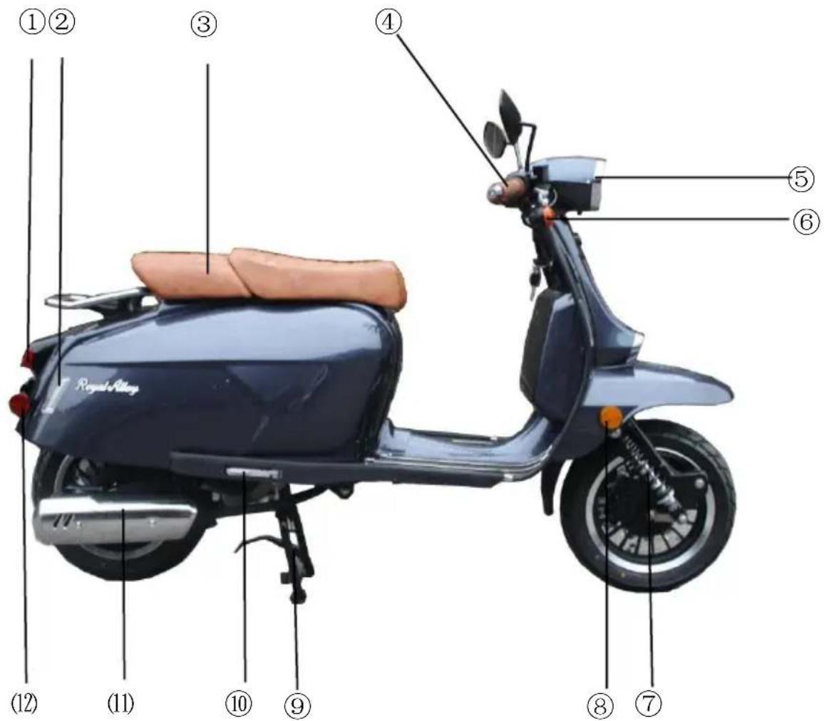
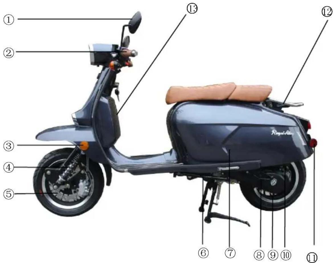
Familiarize yourself with the following parts carefully before using the scooter.
Right Side View:
| 1 Rear light / brake light | 2 Rear turning lamps | 3 Seat |
| 4 Acceleration grip & right switch | 5 Head lamp | 6 Front turning lamps |
| 7 Front right shock absorber | 8 Front right-side | 9 Main stand |
| 10 Rear footrest | 11 Exhaust / Muffler | 12 Rear right side reflector |
text_image
①② ③ ④ ⑤ ⑥ (12) (11) ⑩ ⑨ ⑧ ⑦Left Side View:
| 1 Rear-view mirrors | 2 Left grip switch | 3 Front left side reflector |
| 4 Front left shock absorber | 5 Front disc brake | 6 Side stand |
| 7 Air filter | 8 Kick starter lever | 9 Rear disc brake |
| 10 Rear shock absorber | 11 Rear left side reflector | 12 Rear rack |
| 13 Glove box |
text_image
① ② ③ ④ ⑤ ⑥ ⑦ ⑧ ⑨ ⑩ ⑪ ⑫ ⑬ Royal Rides| Warning |
| Rear rack has a maximum payload of 5 kgs |
Serial Numbers
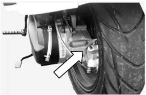
Engine Number
The engine number is stamped on the rear of the crankcase assembly.

Note

Use your engine number for convenience in purchasing correct spare parts from your dealer.
Chassis Number
The chassis number is stamped on the right-side frame rail.
natural_image
Close-up of a motorcycle's wheel and tire assembly with visible mechanical components (no text or symbols)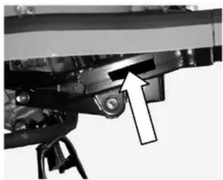
natural_image
Mechanical assembly diagram showing a bracket with a white arrow pointing to a component (no text or symbols present)Engine number Chassis number
Please write down your scooter's serial numbers below for future reference.
| Chassis Serial No.: |
| Engine Serial No.: |
Control Functions
Instrument Panel Indicators
text_image
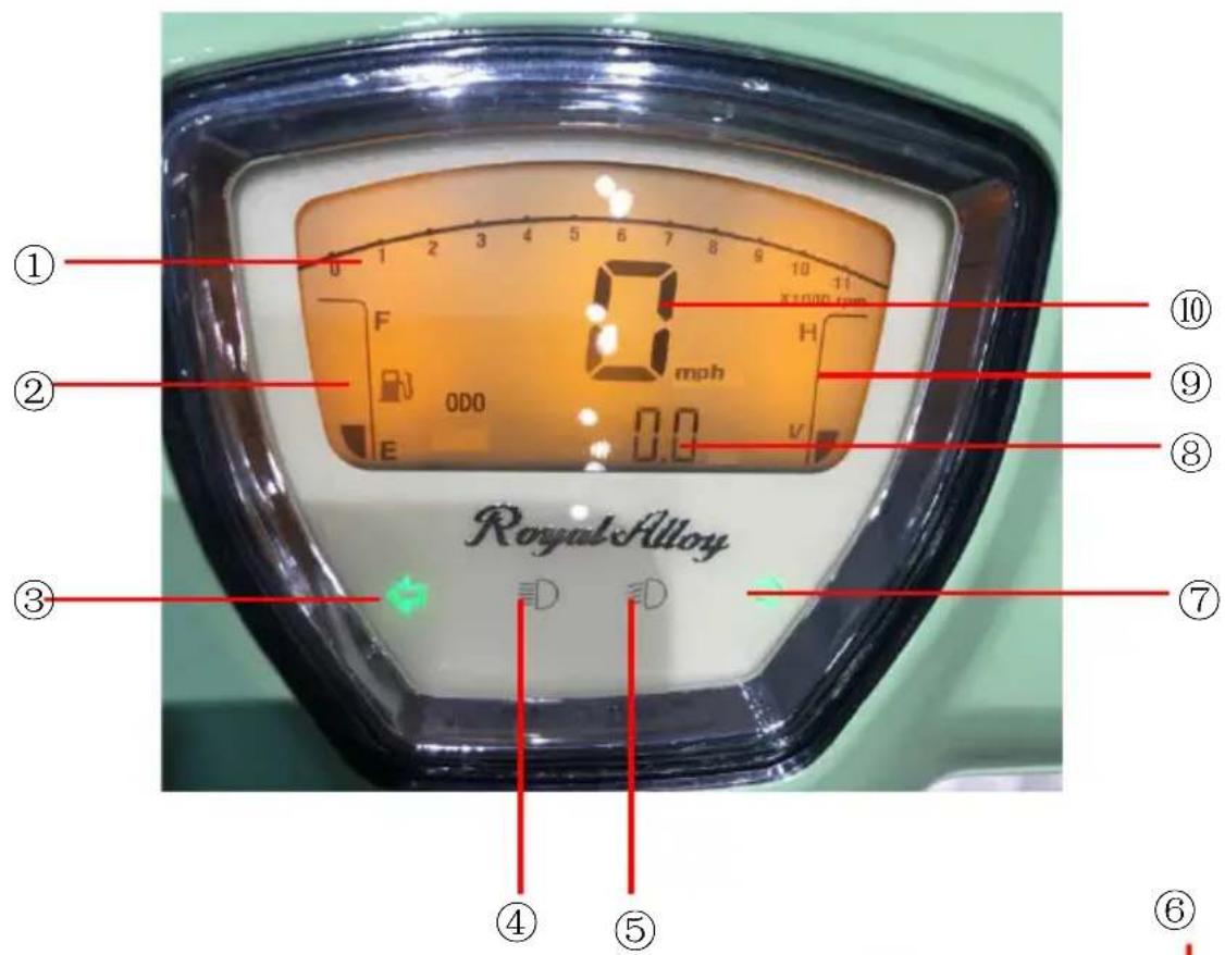
① ② ③ ④ ⑤ ⑥ ⑦ ⑧ ⑨ ⑩ 0 mph 0.0 E F 0DO Royal Alloy1) ① Tachometer
2) ② Fuel Gauge
3) ③⑦ Left /Right Turn Signal Indicator
4) ④⑤ High/Low Beam Indicator
5) ⑥ Trip Odometer Function Button
6) ⑧ Odometer (mile)
7) ⑨ Battery Voltage Indicator
8) ⑩ Speedometer (mph)
natural_image
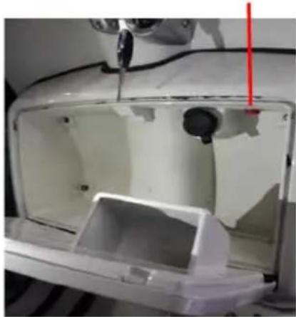
Interior view of a white plastic appliance with internal components and a red vertical line marker (no text or symbols visible)① Tachometer
The indicator will show the engine RPM.
② Fuel Gauge
This will show the fuel volume remaining in the fuel tank. When the pointer points to “F”, the fuel tank is full. When the pointer moves low toward “E”, the fuel level is low and refilling is necessary.
③ ⑦ Left and Right Turn Signal
When the turn signal switch is set to left, the Left Direction Indicator will flash. When the turn signal switch is set to right, the Right Direction Indicator will flash. Press the button toward the bar to stop indicator.
④ ⑤ High/Low Beam Indicator
⑥ Trip Odometer Function Button
Changing Display between TRIP METER & ODOMETER:
- Turn the ignition key to the on position.
- Press the “MODE” button and release.
- Clear the trip counter history – When the display reads TRIP METER, press the “MODE” button and hold for 5 seconds, then release when zero is displayed.
Changing between MPH & Km:
- When the display reads ODOMETER, press the “MODE” button and hold for 5 seconds then release.
⑧ Odometer
The odometer registers the total distance the scooter has been ridden.
⑨ Battery Voltage Indicator
Indicates the battery voltage. When the level shows “H”, the battery is fully charged. When the level drops toward the bottom, the battery charge is low, recharge replacement is necessary.
⑩ Speedometer
Indicates the speed at which you are riding in MPH.
Ignition Switch
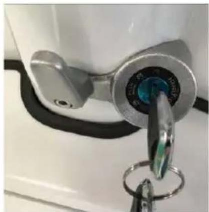
Rotate the key to turn power ON or OFF.
| ON | Starts EngineScooter fully operationalCannot remove key until turned off |
| OFF | Turns Engine OffKey can be inserted or removed |
| LOCK | Steering bars can be locked to one directionKey can be inserted or pulled out |
When scooter is left unattended, you can choose to lock the steering handlebars to prevent theft.
-
Turn the handlebars left.
-
Insert key into OFF position. Press the key in and turn it counterclockwise to LOCK position.
-
Pull out key.
-
Swing handlebars to check if they are locked.
-
To unlock the handlebars, move the key from LOCK position, and turn clockwise (without pressing) to OFF position.
natural_image
Close-up of a metallic key inserted into a lock, with no visible text or symbols| ⚠️ | Note |
| ✨ | If you are having difficulty locking the scooter, turn handlebars slightly to the right and try again. |
Handlebar Switches
text_image
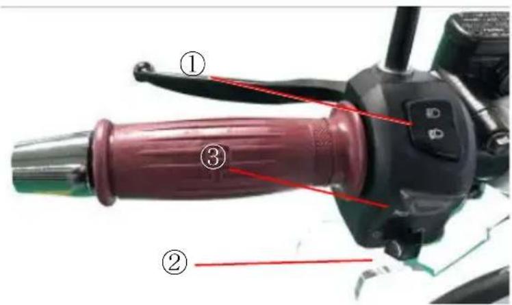
Labeled diagram of a motorcycle handle and grip with numbered parts, likely for assembly or maintenance instructions.① Beam Switch
Use this to change headlamp beam. When switch is turned to:
| HIGH | High beam is on. |
| LOW | Low beam is on. |
② Turning Signal Lamp Switch
Use this to turn left/right signal lamps on or off to notifying other drivers that you are turning left of right.
Switch is turned to:
| Right | Right signal lamps flash. |
| Left | Left signal lamps flash. |
| Center | No signal lamps are on. |
③ Horn Button
Press this button to sound horn.
text_image
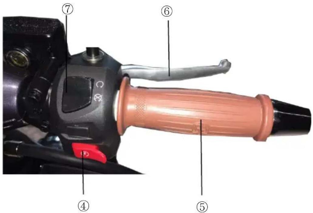
Labeled diagram of a camera control lever with numbered parts for identification④ Starter Button
Use this to start engine. To start ignition key to ON, squeeze the rear brake lever and press button (#7 on image below).
⑤ Throttle Grip
This is used to control engine speed. Rotate throttle toward yourself (counterclockwise) to increase engine speed. Rotate throttle away from yourself (clockwise) to decrease engine speed.
⑥ Brake Lever
By operating brake levers, you can control the speed of the scooter. You can decrease your speed or come to a full stop when the lever is fully depressed. Brake is applied by squeezing brake lever gently towards the grip. Rear brake light will illuminate when lever is squeezed.
⑦ Engine Stop
Press this button to turn off engine in the event of an emergency. Use the ignition switch to stop the engine in all other circumstances.

text_image
Labeled diagram of a bicycle suspension system with numbered components⑧ Kick Starter Lever
This scooter is equipped with a kick starter located on the left side of the engine. To start the engine, place scooter on the main stand and depress the kick starter lever forcefully.
⑨ Main Stand
To use the main stand, depress it by foot until the stand is touching the floor and lift the rear of the scooter backwards until the stand is securely in place with the rear wheel off the ground. Use the rear rack to assist in lifting the scooter upwards and backwards.
Always ensure that the scooter is on level ground or pointing uphill on hard standing before putting the scooter on the main stand.
Never put the scooter on the stand if the machine is pointing downhill or the floor is uneven or on soft or loose ground.
⑩ Main Stand Side Stand
To use the side stand, depress the end of the stand until it rotates towards the front of the scooter and stops.
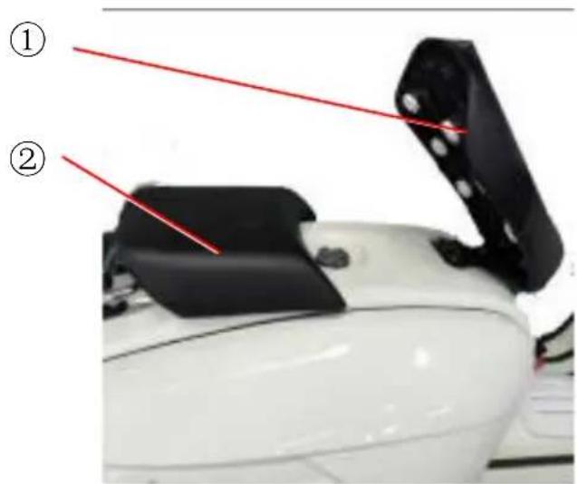
Seat Lock (1)
text_image
Labeled diagram of a white electronic device showing two components with red annotations pointing to them.To open the seat as follows:
Carefully lift the rear of the front seat with your hands, the seat will lift open.
To close the seat as follows:
Carefully push down the rear of the seat, the seat is secured to the center section ② by the sucker ①, the seat will be locked.
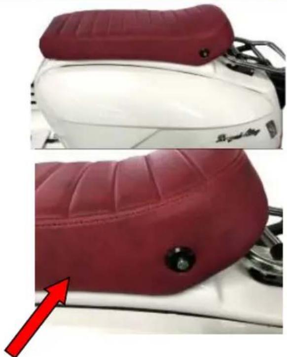
Seat Lock (2)
natural_image
Close-up of a red and white motorcycle seat with a black button, showing surface texture and a red arrow pointing to the side (no text or symbols)To open and close the seat as follows:
-
The seat release button is located on the left-hand side and to the rear of the seat, push the button in and the seat will open.
-
To close the seat gently lower the seat down onto the locking pin.
Fuel Tank Cap
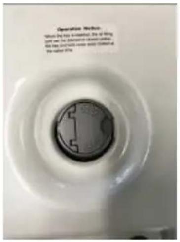
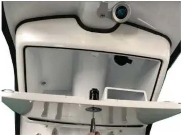
To access the fuel cap, open the seat. To open the fuel cap, insert the ignition key into the cap and turn the fuel cap tab clockwise. Please note: Don't use the key to rotate the cap since this can cause the key to break. The key and the lock cover should be rotated at the same time. Close the fuel cap use the same way.
There is an Operation Notice decal nearby the fuel cap.
Operational Notice
With the key inserted and the lock cover in the upright position, rotate both the key and the lock cover simultaneously to open and close the fuel cap.
text_image
Operation Method When the press is connected, the of being lack was to be disordered closed under. the press and hold side (body) contained the rated 50%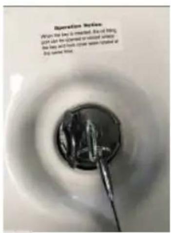
text_image
Operation Version When the lapel is melted, the oil being light can be opened or sealed within the laps and marks the lapel's section expanded at stop current laps.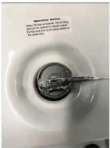
text_image
Description. Service. When the body is attached, that of lifting plumb can't be fastened or reduced without the face and neck, such as thick horizontal lines, so far. Use: 100%Front Luggage Box
natural_image
Interior view of a white appliance with a camera and mechanical components, no visible text or symbols
Caution
Do not keep breakables in luggage box.
Do not keep valuable items in luggage box.
Do not place fuel and/or oil in luggage box.
Only store water-proof items in luggage box
Fuel and Oil Requirements
Fuel
Use unleaded fuel with an octane rating of 87 or higher. Check fuel level prior to each ride.
Engine Oil
Genuine Motor Oil is the oil brand recommended by Royal Alloy. Your scooter operates under intense conditions, including higher engine speed, hotter temperatures, and higher compression ratios than other vehicle types. These conditions subject the oil to significant operational stress and require a lubricant specifically designed for scooters.
Only use JASO MB 15W-40 engine oil in your engine.
JASO MB oils are very low friction oils formulated for use in engines that do not have wet clutch systems. Other oil types may severely damage your engine and void any warranty.
All JASO rated oils will display the JASO oil classification on the bottle within an outlined border.

text_image
M001GEN001 MBMany oils claim to “meet or exceed” JASO ratings but are not officially certified. If an oil does not have a 10-character oil code and the JASO MB rating prominently displayed on the label, then the oil is not certified by JALOS and should not be used in your scooter.
CHECK YOUR ENGINE OIL LEVEL BEFORE EACH RIDE
Transmission Oil
Genuine Motor Oil is the brand recommended for use in your Royal Alloy Scooter.
Use good quality GL-4 85W-140 gear oil. Check gear oil regularly and change oil according to maintenance schedule.
Breaking-in of New Scooter
The first 500 miles are the most important in the life of your scooter. Proper breaking-in operation during this period will help ensure maximum life and performance from your new scooter. The parts are manufactured with high quality materials, and machined parts are finished to close tolerances. Breaking-in allows the machined surfaces to lap each other and mate smoothly. Freeing up of internal parts is achieved after approximately 60 running hours, and during this breaking-in period the engine will loosen up and performance will improve.
Maximum Throttle Operation Recommendation
This table shows the maximum recommended throttle operation during the break-in period.
| Initial 500 miles | Less than 1/2 throttle |
| Initial 1000 miles | Less than 3/4 throttle |
Vary the engine Speed
Engine speed should be varied and should not be held at a constant speed. This allows the parts to be “loaded” with pressure, and then unloaded, allowing the parts to cool. This aids the mating process of the parts. It is essential that some stress be placed on the engine components during breaking-in to ensure this mating process. Do not, apply extensive load on engine.
Avoiding Constant Low Speed
It is not beneficial when breaking in the engine to operate it at a constant low speed. Allow engine to accelerate freely within the recommended maximum limits. Do not, however, use full throttle for the first 1000 miles.
Allow Engine Oil to Circulate Before Riding
Allow sufficient idling time after warm or cold engine start up before applying load or revving up engine. This allows time for lubricating oil to reach all critical engine components.
First Service
The first service is the most important service your scooter will receive. During breaking-in, all engine components will have bedded in, and all other parts will have seated in. All adjustments should be restored, all fasteners should be tightened, and the old oil should be replaced.
Timely first service will ensure optimum service life and performance from the engine.
| Caution | |
| ✧ First service should be performed as outlined in the inspection and maintenance section of this manual. |
Inspection Before Riding
Before riding your scooter, be sure to check the following items. Never underestimate the importance of these inspections. Perform all checks before riding the machine, each time.
Battery Connection
| Warning | |
| ✧ Before checking the following items, ensure battery voltage is adequate and battery is connected firmly. |
| ITEM | INSPECTION |
| Steering | SmoothnessNo restriction of movementNo play or excessive movement |
| Brakes | Correct brake lever free playNo obstruction in braking |
| Tyres | Correct pressureAdequate tread depthNo cracks or cuts |
| Fuel | Enough fuel for the planned distance of the journey. |
| Lights | Operate all lights – headlamp, tail lamp, brake lamp, turning lamps |
| Indicators | Oil indicator (if fitted) and turning indicators |
| Horn | Correct function and operation |
| Engine oil | Sufficient oil levels. |
| Throttle | Correct play in throttle cableSmooth operation and positive return of throttle grip to closed position when released |
Braking Effect and Brake Free Play Inspection
Activate each brake lever until resistance is felt, measuring the distance the lever end has moved. Distance should be 10-20mm.
Front Brake and Anti-Dive Linkage Inspection
Verify anti-dive link bar has free movement by twisting from side to side. If any excessive play is found in the up and downward movement, remove and inspect/replace as required.
Tyre Inspection
1. Tyre Pressure
Check level of wear on the tyre, and determine the tyre pressure using the pressure gauge. If pressure does not match pressures shown in table below, adjust to the correct level.
Correct tyre Pressure
| Front Wheel | 29 psi |
| Rear Wheel | 32 psi |
| ⚠️ Note |
| ✧ Always carry a tyre pressure gauge with you in your glove box. |
- Cracks, Damage, Foreign Objects and Abnormal Wear
Check surface of tyre for:
☆Obvious damages
✨Nails, stones, glass, etc.
✨Abnormal wear
Fuel Inspection
Ensure fuel level is sufficient to reach your destination. Turn ignition switch to the “ON” position to see fuel level. If fuel gauge indicates low fuel level, fuel should be refilled as soon as possible.
Engine Oil Inspection

Warning

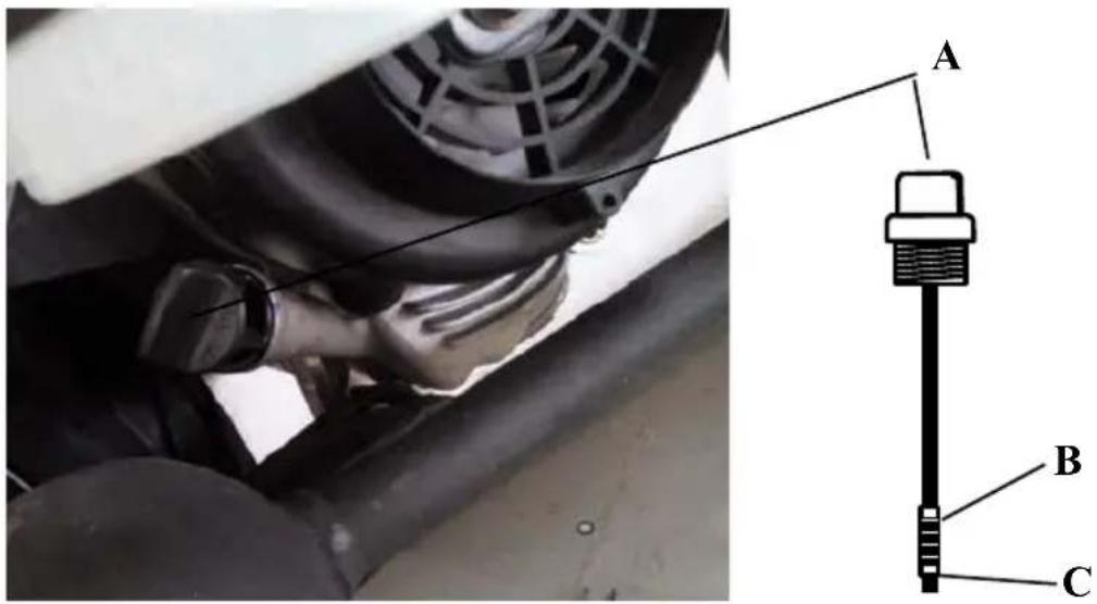
Always ensure the oil level is maintained near upper level, Mark "B." Never allow oil level to exceed the upper mark or fall below the lower Mark "C", as this can cause severe engine damage.
text_image
Technical diagram showing a mechanical component with labeled parts A, B, and C, likely illustrating a mounting or mounting assembly.Steps for Engine Oil Inspection
- Place vehicle in upright and level position.
- Start engine, allow to idle for a few minutes, then stop engine.
- Wait at least five minutes to let oil inside engine to run back down into crankcase.
- Loosen refilling oil cap/dipstick and remove.
- Clean dipstick of oil residue, and insert oil filler cap.
• DO NOT screw in cap to avoid inaccurate measurement and engine damage.
- Remove dipstick again to check oil level. Must be between the reference Marks “B” and “C.”
-
If necessary, fill oil with JASO MB 15W-40 oil to the reference Mark “B” level. Oil level should not exceed “B” mark.
-
Tighten dipstick securely.
Transmission Oil Inspection
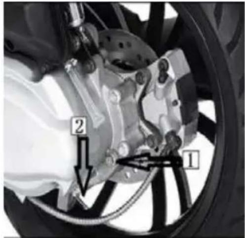
text_image
Technical diagram of a car brake system with labeled components 1 and 2, showing mechanical assembly and valve mechanism.-
Warm up engine to normal operational temperature, then turn off engine; wait approximately 5 minutes.
-
Place scooter on the parking center-stand.
-
Remove oil filler screw, and check oil level. Level should be just below the oil-filler opening.
-
If necessary, replenish transmission oil with GL-4 85W-140 via oil-filler opening.
-
When changing transmission oil, open drain plug until all transmission oil flows out. Then, tighten plug, and add new oil via oil-filler opening.
-
Tighten oil filler screw.
Ignition Unit and Lights Inspection
-
Start engine, and turn on headlamp switch, and ensure headlight and rear light are on.
-
Use front and rear brake separately, checking to ensure brake light is working.
-
Use turning signal lamp switch, and check if turn signal lights are properly functioning.
Rear View Mirrors Inspection
- Ensure rear and side views can be seen clearly from mirrors when seated in the riding position.
- Ensure rear mirror is clean and free of damage. Check tightness on handlebar mounting.
Reflectors and License Plate Inspection
- Ensure license plate and reflectors are clean and undamaged.
- Ensure that license plate is fixed securely, and registration number is clearly visible.
Riding Tips
Start Engine

Caution

Before starting, you must:
- Check quantity of fuel and engine oil.
- Place scooter onto center stand.
- Do not use kick starter lever if bike is not on main stand.
- Apply brake/s
Insert ignition key into ignition switch and turn to ON position.
When engine is cold:
- Squeeze rear or front brake lever, and keep throttle closed.
- Push starter button or depress kick starter lever.
- As engine fires, apply a small amount of throttle, and let engine warm up after being started.
When the engine is warm:
- Squeeze the rear or front brake lever.
- Open throttle 1/8-1/4.
- Push starter button or depress the kick starter lever.

Caution
✿ Release starter button soon after engine is started to avoid damage to starter motor and gear wheels.
If engine des not start after several attempts, turn throttle grip by 1/8-1/4, and try again. Grip should be released soon after engine is started. If this fails, and in order to protect the battery from discharging totally, try restarting using the kick-starter. Also, check for any problems with the starting system.
Preparing to Drive
- Release main stand.
- Mount scooter.
While holding handlebars with both hands and applying brakes, mount scooter from left side and sit on seat. Support yourself with your left foot.
| Caution |
| Do not turn throttle grip before you are ready to ride. |
- Check surroundings for safety. Keep brake lever squeezed until you are ready to begin driving.
- Use turning indicator to enter traffic.
| Caution |
| Special attention should be paid to the traffic approaching you from behind. |
- Begin driving.
Release rear brake lever, and gradually rotate throttle grip, letting scooter gradually accelerate.
| Caution |
| ◇ Excessive rotation of grip can lead to the danger of sudden acceleration. |
- Adjust Speed
The speed of your scooter can be adjusted by turning the throttle grip. Rotate grip towards yourself to speed up (counterclockwise). Gradual rotation is recommended. Rotate grip back clockwise to slow down.
- Apply Brakes
Combined application of both brakes is recommended for maximum stopping power and even brake wear.
8. Slowing Down and Braking
Quickly release throttle grip or rotate backwards (clockwise) to decelerate scooter. Squeeze both brake levers simultaneously to bring scooter to a stop. It is advisable to reduce the speed by gradual application of the brakes. Combined application of both brakes is recommended for maximum stopping power and even brake wear.
| Caution | |
| ✧ Using only the front or rear brake individually may cause a side slide. Harsh braking and sharp turning are two of the major causes of loss of traction and crashes. |
Special care should be taken in rainy and wintery conditions.
Damp or wet road surfaces may reduce level of grip and cause skidding. Sharp turning during acceleration should be avoided, and an appropriate distance should be kept from the vehicles ahead. Please be mindful that the braking distance can double in rainy an icy condition.
Skidding may occur on wet roads, therefore concentrate, and be ready to apply the brakes cautiously at any time. Check brakes after washing scooter or riding through water.
After washing the scooter or riding through standing water, braking effect may be reduced. If this occurs, observe slow riding and gentle braking to allow time for the brakes to restore to normal function.
| Caution |
| ✧ To prevent scooter from falling off main stand, never park scooter facing down on a slope, or park it on a loose or soft surface. |
Lock the handlebar
When parking scooter, lock handlebar to prevent theft.
Inspection and Maintenance
The maintenance schedule indicates the intervals between periodic services in miles and months. At the end of each interval, scooter must be inspected, lubricated and/or serviced. If scooter is used under heavy load conditions, such as continuous full throttle operation or used in dusty environments, certain services should be performed more often to ensure reliability of machine. See Maintenance Section for further explanation. Additionally, see dealer for further guidelines. Steering components, suspension and wheel components are key items and require diligent and competent servicing. For maximum safety, inspecting and servicing by an authorized and/or qualified dealer is recommended.
First Maintenance
The first maintenance is the most important. During running in, all engine parts will have been matched to each other, bedding in will have occurred with other parts. All parts should be readjusted, fasteners tightened, and contaminated engine oil and filters replaced.
To ensure the engine a long service life and best performance, carry out the first maintenance no later than due date.
| Caution |
| It is recommended to use original replacement parts for all maintenance. All items marked with an asterisk on Maintenance Schedule (p.29) should be serviced by an authorized Royal Alloy dealer. |
Maintenance Schedule
Routine maintenance should be carried out per maintenance schedule below. Items marked with an asterisk (*) are recommended to be performed only by your Royal Alloy dealer. Maintenance should be based on distance or months, whichever comes first.
NOTE: I=Inspect; clean, adjust, lubricate or replace if necessary
C=Clean;
R=Replace;
T=Tighten
| Intervals Distance | 300km186miles | 1,500km932miles | 3,000km1,864miles | 6,000km3,728miles | 9,000km5,592miles | 12,000km7,456miles | 15,000km9,320miles | |
| whichever comes first | Time (Months) | 1 | 3 | 6 | 9 | 12 | 15 | 12 |
| Engine Oil* | R | R | R | R | R | R | R | |
| Coarse Oil Filter | C | C | C | C | C | C | C | |
| Air Cleaner | I | I | I | I | I | I | ||
| Air Filter | I | I | R | I | I | I | ||
| Gear Oil* | I | I | I | R | I | R | I | |
| Disk Brakes | I | I | I | R | I | I | ||
| Clutch Shoes* | I | I | I | I | I | |||
| Tyres | I | I | I | I | ||||
| Wheel | I | I | I | I | I | I | ||
| Front Fork | I | I | I | I | I | I | ||
| Steering Bearings * | I | I | I | |||||
| Rear Absorber | A | A | A | |||||
| Main / Side Stand | I | I | I | I | I | |||
| All Fasteners | I | I | L | I | L | I | L | |
| Battery | I | I | I | I | I | I | ||
| Valve Gap* | I | I | A | I | I | |||
| Spark Plug* | I | I | C | I | R | I | ||
| V-Belt, Rollers | I | R | I | R | I | |||
| Fuel Filter* | I | I | I | I | R | I | ||
| Fuel Lines* | I | I | I | |||||
| Engine Idle Speed* | I | I | I | I | I | I | I | |
| These are scheduled maintenance items. Perform a pre-ride inspection before each ride. | ||||||||
Body Frame Nuts and Bolts
Tighten the bolts and nuts to specified torque after initial 1000km (3 month) and every 4000km (20 month) thereafter.
Specified torque
| No. | Item | N·m | kg·m | Reference |
| 1 | Front axle nut | 53 | 5.3 | / |
| 2 | Handlebar mounting bolt | 49 | 4.9 | / |
| 3 | Steering stem lock nut | 30 | 3.0 | / |
| 4 | Handlebar locating bolt | 25 | 2.5 | / |
| 5 | Front fork mounting bolt | 45 | 4.5 | / |
| 6 | Master cylinder mounting bolt | 10 | 1.0 | / |
| 7 | Brake hose union bolt | 23 | 2.3 | / |
| 8 | Brake caliper mounting bolt | 26 | 2.6 | / |
| 9 | Bleeding valve | 7.5 | 0.75 | / |
| 10 | Front panel bolt | 23 | 2.3 | / |
| 11 | Rear axle nut | 120 | 12.0 | / |
| 12 | Rear shock bolt | 29 | 2.9 | / |
| 13 | Rear brake lever nut | 11 | 1.1 | / |
| 14 | Engine bracket mounting bolt/nut | 98 | 9.8 | / |
| 15 | Engine mounting bolt/nut | 80 | 8.0 | / |
Battery
text_image
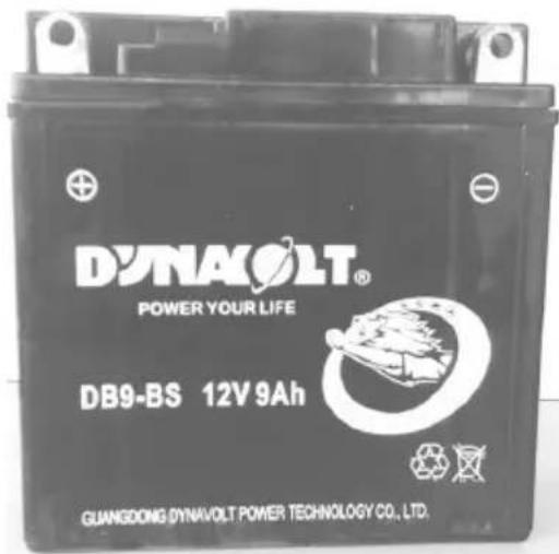
DYNACOLT® POWER YOUR LIFE DB9-BS 12V 9Ah GUANGDONG DYNAVOLT POWER TECHNOLOGY CO., LTD.Battery is located inside removable cover on body section beneath front of seat. This battery is sealed type and requires no fluid level nor gravity maintenance.
Spark Plug
text_image
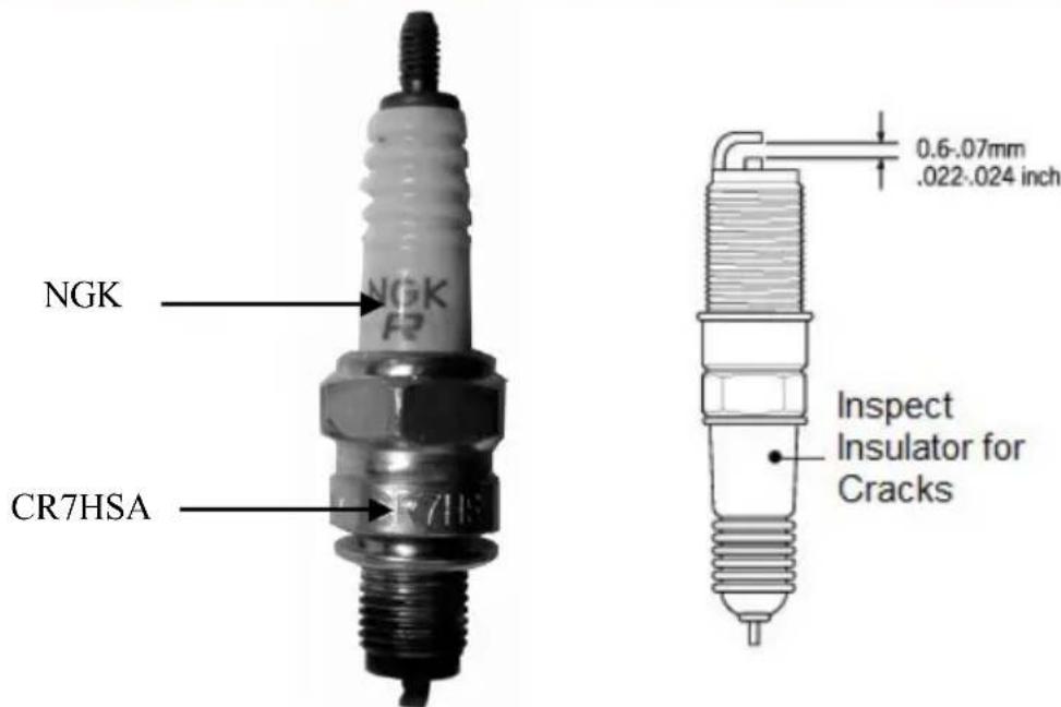
NGK CR7HSA 0.6-0.07mm .022-0.024 inch Inspect Insulator for CracksUse small brass brush or cleaner to remove carbon deposits at first 500 miles or every 3000 miles going forward. Adjust spark plug gap with a thickness gauge to 0.6-0.7mm. Spark plug should be replaced every 6000 miles.
When removing carbon deposits, indicate colour of spark plug porcelain tip. Colour can indicate whether the standard spark plug is suitable for usage, assuming all other parts are running correctly. If standard spark plug is dark black, this may be indicative of short distance trips where engine does not reach full running temperature. A normal operating spark plug should be light brown or tan in colour. If spark plug tip colour is white, this may be due to overheating or lean fuel mixture condition. In this case, scooter should be inspected by authorized dealer and/or qualified service mechanic as soon as possible.

Caution
Do not over-tighten spark plug or cross thread. In order to avoid damage to cylinder head, do not allow the contamination to enter engine through spark plug hole.
The standard spark plug for this scooter has been carefully selected to meet the vast majority of all operation ranges. If spark plug colour indicates a standard spark plug is not applicable for your specific scooter usage, consult an authorized dealer before selecting an alternate plug or heat range. Selection of improper spark plug can lead to severe engine damage.
Fuel Hose
Replace fuel hoses every four years.
Air Filter
The air filter element used in the Royal Alloy Grand Tourer 150 scooter is a polyurethane foam element. If filter element is clogged with dust, intake resistance will increase with a resultant decrease in power output and increase in fuel consumption due to the richer mixture. Check and if necessary.
Remove air filter element according to the following procedures:
- Remove screws.
- Remove two fixing slippers by sliding them rearward.
- Remove air filter cover.
- Remove filter element.
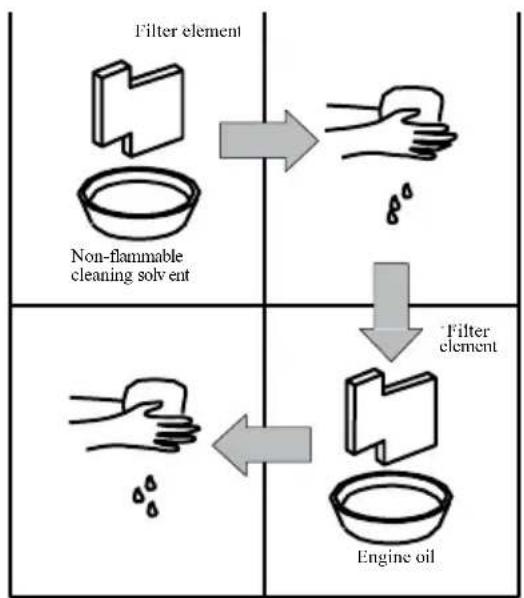
Wash air filter element as follows:
-
Fill a container of a suitable size with non-flammable water soluble cleaning solvent. Immerse filter element in the solvent and wash it clean.
-
Squeeze the solvent off the washed filter element by pressing it between the palms of both hands. Do not twist or wring filter element as this may lead to tearing.
-
Rinse in warm free running water and allow to dry by using compressed air or warm air dryer.
-
Immerse filter element in clean engine oil, squeeze excess oil from filter element, leaving it slightly wet with oil.
-
Reinstall cleaned air filter element in reverse order of removal. Be sure that filter element is securely in position and is sealing properly.
flowchart
graph TD
    A["Filter element\nNon-flammable cleaning solvent"] --> B["-->"]
    B --> C["Filter element\nEngine oil"]
    C --> D["-->"]

Caution
Before and during the cleaning operation, carefully examine air filter element for any tears in the material. A torn filter element must be replaced with a new one.
If driving under dusty conditions, the filter element must be cleaned more frequently.
✿ Never operate engine without filter element. This can lead to irreparable wear.
Always ensure filter element is always in excellent operational condition. The life of the engine depends largely on this single component.
Carburetor
Factory set carburetion is the basis of the performance expected of your engine. The carburetor is factory set for the best carburetion. Do not attempt to alter its setting. There are two items of adjustment possible under normal running: 1. Engine idle speed and 2. Throttle cable slack. Adjust carburetor idle speed end throttle cable slack periodically.
Engine Idle Speed Adjustment
- Start up the engine and let it warm up.
- After engine warms up, turn the throttle stop screw in or out so that engine runs at 1600 ± 200 rpm.
If you have a tachometer, you can do this adjustment by referring to the procedures described above. Engine idle speed should be adjusted only after engine warms up.
Throttle Cable Adjustment
- Loosen lock nut.
- Adjust cable slack by turning adjuster in or out to a slack of 0.5\~1.0mm.
- After adjusting slack, tighten lock nut.
Hydraulic Brake Fluid
For front and rear disk brake model
Grade: DOT4.1
Note:
- Only DOT4.1 glycol-based hydraulic brake fluid is equipped in this vehicle. Do not mix with silicon-based or oil-based brake fluid. This will damage the hydraulic brake system.
- Do not use residual fluid from a previously opened container. Brake fluid can easily absorb unwanted moisture from the atmosphere.
- Do not over-fill or spill brake fluid onto painted surface.
Tyres
Check tyre inflation pressure and tyre tread condition. For maximum safety and good tyre life, the tyre pressures should be inspected on a regular basis particularly before long journeys or with passengers.
Tyre Pressure
Insufficient air pressure in the tyres not only increases tyre wear but also seriously affects the stability of the scooter. Under-inflated tyres make smooth cornering difficult and over-inflated tyres decrease the amount of tyre in contact with the ground, which can lead to skids and loss of control. Be sure that the tyre pressure is always within the specified limits. Tyre pressure should only be adjusted when the tyres are cold.
Cold Inflation Tyre Pressure
| Front Wheel | 29 psi |
| Rear Wheel | 32 psi |

Caution
✿ Tyre inflation pressures and general tyre conditions are extremely important to the proper performance and safety of the scooter. Check your tyres frequently for both wear and correct inflation pressures
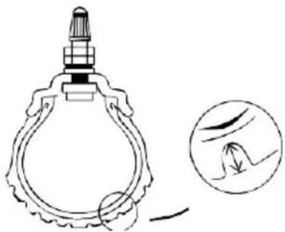
Tyre Tread Condition
natural_image
Line drawing of a decorative lamp with a circular base and handle, accompanied by an inset showing a hand dipping into the nose (no text or symbols)Operating scooter with excessively worn tyres will decrease riding stability and can lead to loss of control. It is recommended that a tyre be replaced when remaining depth of tyre tread is 1.6mm or less.
| Caution | |
| ✧ Standard tyres on scooter are 110/70/12 front and 120/70/12 rear.Use of a larger tyre may result in clearance issues. |
Fuse
The fuse is located next to the battery. If there is any electrical system failure, first check the fuse. In case the fuse blows, there is a 10A spare fuse.
| Caution | |
| ✧ | Always replace blown fuse with correct amperage fuse. Never use substitutes, e.g. aluminum foil or wire, to replace a blown fuse. If spare fuse blows shortly after installation, there may be a major electrical problem. Consult dealer or a qualified service mechanic immediately. |
Troubleshooting
If engine refuses to start, perform following inspections to determine the cause:
- Is there enough fuel in fuel tank?
- Is there fuel reaching carburetor from fuel tank?
- Loosen the carburetor drain plug and drain the fuel in the carburetor. Refit the drain plug.
- Depress kick-starter lever several times.
- Loosen drain plug and check to ensure there is fuel is in the carburetor.
- If it has been determined that fuel is reaching carburetor, ignition system should be checked next. Remove spark plug and re-attach it to spark plug head.
| Caution |
| Do not allow fuel to spill. Do not allow any fuel to come into contact with hot engine, exhaust, or ignition system. Extinguish any smoking materials from any other fire or heat source. |
- While holding spark plug firmly against engine, crank engine with ignition switch in ON position. If ignition system is operating properly, a blue spark should jump across spark plug gap. If no spark occurs, consult dealer for repairs.
| Caution | |
| ✧ | Do not hold spark plug close to open spark plug hole inside cylinder head, as gasoline vapor inside cylinder could be ignited, which can possibly start a fire. |
| ✧ | To reduce chance of electrical shock, hold outer steel shell of spark plug against an unpainted metal portion of engine. Due to possibility of electrical shock, anyone with a heart condition or pacemaker should delegate this task to an authorized dealer or mechanic. |
Engine Stalling
- Check fuel supply in fuel tank.
- Check ignition system for intermittent spark.
- Check engine idle speed.

Caution

Consult authorized dealer before attempting to repair any possible problems, especially if machine is within warranty. Tampering with machine yourself while under warranty may affect warranty consideration.
Storage Procedures
If scooter is to be left unused for extended period (e.g. winter storage) the machine needs special servicing requiring appropriate materials, equipment and skill, for this reason, we recommend that you trust this maintenance work to the dealer. If you need to service machine for storage yourself, follow the general guidelines below.
Scooter
Place the scooter on main stand and thoroughly clean entire scooter.
Fuel
- Drain fuel tank.
- Drain carburetor or run engine for several minutes until remaining fuel has been consumed.
Battery
- Remove battery from scooter.
- Clean outside of battery with mild detergent and remove any corrosion from terminals and wiring harness connections.
- Store battery above freezing temperature and connect a suitable battery trickle charger/conditioner.
Tyres
Inflate tyres to normal specifications. See page 35
External
- Spray all vinyl and rubber parts with rubber preservative.
- Spray unpainted surfaces with rust preventative (e.g. WD40). Coat painted surfaces with quality brand car wax.
Returning to Service Procedure
- Clean entire scooter.
- Fuel with standard unleaded fuel.
- Remove spark plug. Turn engine a few times by depressing kick-starter lever. Ensure ignition is in OFF position. Reinstall spark plug.
- Reinstall fully charged battery.
- Adjust pressure of tyres as described in Tyre section. Page 23 Lubricate all places as instructed in this manual.
- Conduct the inspection before riding, as listed in this manual.
Specifications
| Model | GT150 |
| Overall size(mm) Wheel | 1845×670×11151390 |
| Net weight (Kg)Max loading weight(kg)Fuel tank capability (L) | 13028010.5 |
| Engine modelEngine idle speedEngine typeBore × stroke (mm)Total displacement (ml)Compression rationMax net power, rate (kW/r/min)Max net torque, rate (Nm/r/min)Start modeEngine oil(950ml)Lubrication typeTransmission oil 170mlFuel type | 1P57QMJ1600 ± 200 rpm1 cylinder, horizontal,57.4 × 57.8149.610.5:18.0/800010.0/ 6000ElectricJASO MB 15W-40Pressure/splashAPI GL-4 85W-140Octane rating of 87 or higher |
| Tyre typeFront tyre sizeRear tyre sizeInflation PressureFrontRearFront brakeRear brakeSpark plugHead lampTurning lampTail lamp/ Brake lampInstrument indicatorBattery capacityFuseHornMax noise | 110/70-12120/70-1229 PSI32 PSIDisc brakeDisc brakeNGK CR7HSA12V 35/35W12V LED12V LED12V 3W12V 9Ah10A12V 1.5A, 90-100dB(A)≤7m ≤80dB(A) |
Reporting Safety Defects
If you believe that your vehicle has a defect which could cause a crash or could cause injury or death, you should immediately inform the National Highway Traffic Safety Administration (NHTSA) in addition to notifying Royal Alloy and Chicago Scooter Company.
If NHTSA receives similar complaints, it may open an investigation, and if it finds that a safety defect exists in a group of vehicles, it may order a recall and remedy campaign. However, NHTSA cannot become involved in individual problems between you, your dealer, or Royal Alloy.
To contact NHTSA, you may either call the Vehicle Safety Hotline toll-free at 1-888-327-4236 / Hearing Impaired (TTY): 1-800-424-9153; go to http://www.safercar.gov; download the SaferCar mobile application; or write to Administrator, NHTSA, 1200 New Jersey Avenue, SE, Washington, DC 20590. You can also obtain other information about motor vehicle safety from http://www.safercar.gov
This owner's manual should always remain in your vehicle for reference. This manual should be considered as a permanent part of your vehicle. The information contained within this manual is the latest available at the time of publication. Royal Alloy reserves the right to make changes to products and publications at any time without notice. There may be information in this manual that differs slightly from your vehicle as improvement and changes occur regularly.
MEMO:
NO COPIES!
Operation Manual

RA Engineering Co., Ltd