
IB-PL200D - Network card / adapter Icy Box - Free user manual and instructions
Find the device manual for free IB-PL200D Icy Box in PDF.


| Product Type | Powerline Ethernet Bridge (adapter) |
| Brand | Icy Box |
| Model | IB-PL200D |
| Color | White |
| Transfer Speed | Up to 200 Mbit/s |
| Maximum Distance | Up to 300 meters over AC wiring |
| Number of Adapters in Package | 2 |
| Maximum Adapters in Network Group | 6 |
| LAN Standards | 10BASE-T, 100BASE-T |
| Encryption | AES 128-bit |
| Power Consumption (Standby) | < 1 Watt |
| Power Consumption (Full Load) | 3.8 - 4.3 Watt (220-240 V) |
| Operating Temperature | 0°C to 40°C |
| Storage Temperature | -20°C to 60°C |
| Relative Humidity (Operating) | 10% to 85% (non-condensing) |
| LED Indicators | Power, Ethernet Link/Activity, PLC Link/Activity |
| Buttons | GROUP, RESET |
| Ethernet Port | RJ45 (10/100 Mbps) |
| AC Pass-through | No |
| Operating System | OS independent |
| Safety | Do not install with vent holes facing down; unplug before cleaning; keep away from water and heat; use only qualified technician for service. |
| Cleaning | Use a dry cloth; do not use liquid cleaners. |
| Dimensions (each adapter) | Approx. 60 x 40 x 30 mm |
| Weight (each adapter) | Approx. 100 g |
Frequently Asked Questions - IB-PL200D Icy Box
User questions about IB-PL200D Icy Box
0 question about this device. Answer the ones you know or ask your own.
Ask a new question about this device
Download the instructions for your Network card / adapter in PDF format for free! Find your manual IB-PL200D - Icy Box and take your electronic device back in hand. On this page are published all the documents necessary for the use of your device. IB-PL200D by Icy Box.
USER MANUAL IB-PL200D Icy Box
natural_image
White ICYBOX powertrain electric bridge side heater with ventilation slots and a small plug (no text or symbols visible on device body)INHALTSVERZEICHNIS
ALLGEMEINE HINWEISE....3
VERPACKUNGSINHALT 4
PRODUKTINSTALLATION....7
natural_image
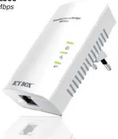
White ICYBOX device with green indicator lights and ports, no visible text or symbols on the device itself.IB-PL500
500 Mbps
natural_image
White ICYBOX device with ventilation slots and ports, no visible text or symbols on the device itself.natural_image
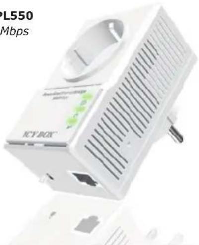
White ICYBOX device with ventilation slots and ports, no visible text or symbols on the device itself.IB-PL550
500 Mbps
natural_image
White electronic device labeled 'ICV-BOX' with ventilation grille and ports (no readable text or symbols beyond branding)VERPACKUNGSINHALT
© Copyright 2012 by RaidSonic Technology GmbH
IMPORTANT SAFETY INSTRUCTIONS....15
PRODUCT OVERVIEW 16-17
PRODUCT INSTALLATION....18
Create private PLC network 18
Remove a device from a logical network Group 19
STANDBY MODE....19
AC outlets connection 19
Connection via power strip....19
Electrical interference 19
SPECIAL CARE FOR BUSINESS INSTALLATION 20
TECHNICAL DATA 21
ORDERING INFORMATION
This user manual describes PLC Powerline to Ethernet Bridge and Powerline to Ethernet Bridge with AC pass-through devices. PLC stands for Powerline Communication.
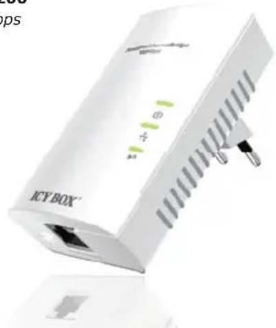
The Powerline to Ethernet Bridge device converts the Ethernet packets from its Ethernet port to the Powerline Communication packets (PLC packets), which then run on home electrical power lines, and is converted back to Ethernet packets by PLC devices at other end of the electrical power lines.
The Powerline Ethernet Bridge with AC pass-through device is a Powerline Ethernet Bridge with extra AC socket. This device includes filter circuit to ensure powerline communication quality and distances by filtering out some band of the electric noises generated by other electrical devices which plugs on the pass-through socket.
Powerline Ethernet Bridge
IB-PL200
200 Mbps
natural_image
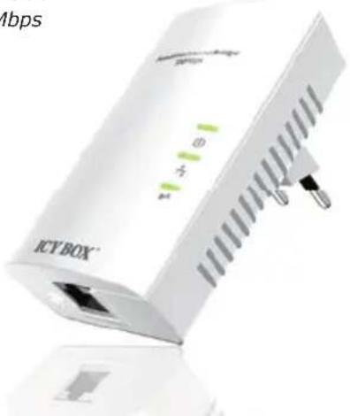
White ICYBOX device with ports and indicator lights (no readable text or symbols)IB-PL500
500 Mbps
natural_image
White ICY BOX 3.01 microcontroller with ventilation slots and ports (no visible text or symbols on device body)Powerline Ethernet Bridge with AC pass-through
IB-PL250
200 Mbps
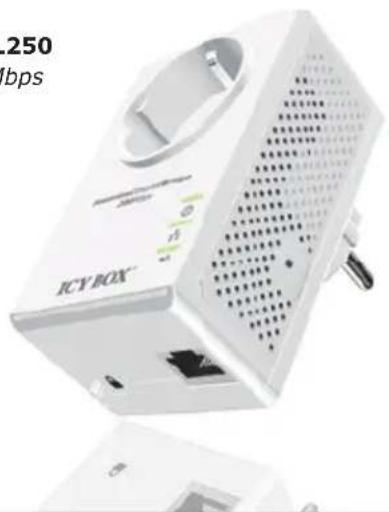
natural_image
Exterior view of a white ICY-BOX device with ventilation slots and ports (no readable text or symbols)IB-PL550
500 Mbps
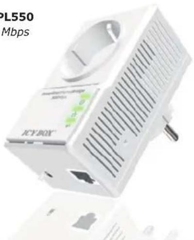
PACKAGE CONTENT
| Powerline Ethernet Bridge | |||
| Model Transfer speed Colour Package content | |||
| IB-PL200 | Up to 200 Mbit/s | White | 1x Powerline adapter, 1x Network cable, 1x Quick installation guide |
| IB-PL500 | Up to 500 Mbit/s | White | 1x Powerline adapter, 1x Network cable, 1x Quick installation guide |
| Powerline Ethernet Bridge with AC pass-through | |||
| Model Transfer speed Colour Package content | |||
| IB-PL250 | Up to 200 Mbit/s | White | 1x Powerline adapter, 1x Network cable, 1x Quick installation guide |
| IB-PL550 | Up to 500 Mbit/s | White | 1x Powerline adapter, 1x Network cable, 1x Quick installation guide |
IMPORTANT SAFETY INSTRUCTIONS
This product is intended for connection to the AC power line. For installation instructions, refer to the Installation section. The following precautions should be taken when using this product.
- Please read all instructions before installing and operating this product.
- Please keep all instructions for later reference.
- Please follow all warnings and instructions marked on the product.
- For safety reason, when device is being powered on, this product should NOT be installed in any electric socket which makes the surface with venting holes on the product to face downward (facing the floor).
- Unplug the Powerline device from the wall outlet before cleaning. Use a dry cloth for cleaning. DO NOT use liquid cleaners or aerosol cleaners.
• DO NOT operates this product near water.
• This product should never be placed near or over a radiator, or heat register.
- This product relies on the building's electrical installation for short-circuit (over current) protection.
- DO NOT allow anything to rest on the product interconnect plug. DO NOT locates this product where people may walk on the cords.
- Because this product sends data over the power line, it is recommended that you plug directly into a power outlet. Do not plug the device into a UPS or power strip with surge protection. The product has its own power filter for protection against surges.
- Only a qualified technician should service this product. Opening or removing covers may result in exposure to dangerous voltage points or other risks.
PRODUCT OVERVIEW
IB-PL200 / IB-PL500
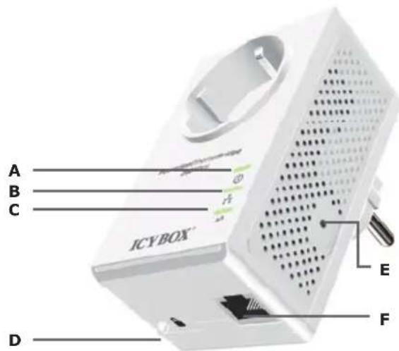
IB-PL250
IB-PL550
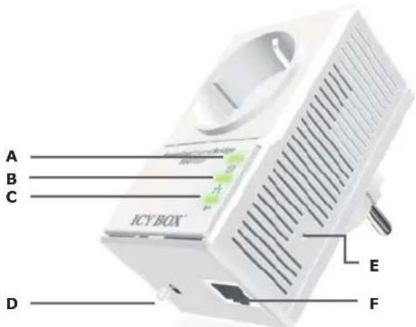
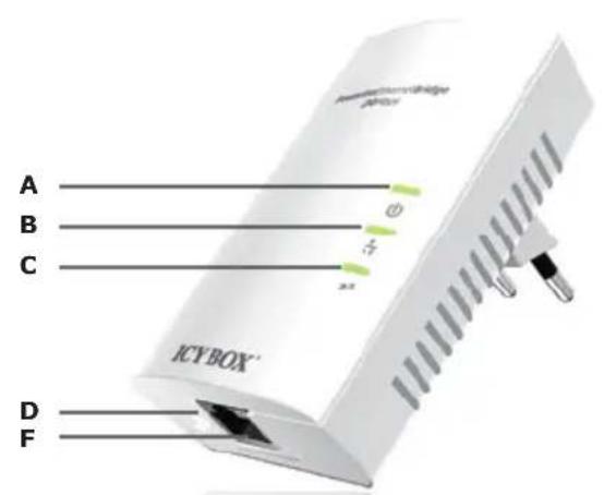
| A | Power LED | B | Ethernet Link/Activity LED | C | PLC Link/ Activity LED |
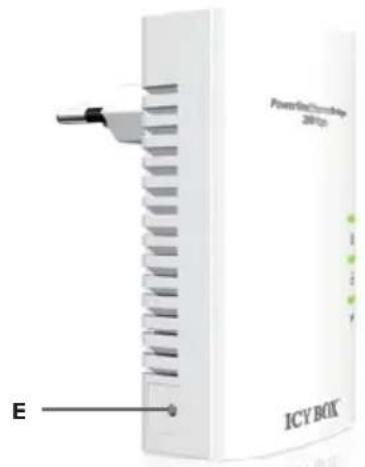
| D | GROUP Button | E | RESET Button | F | Ethernet connection |
Powerline Adapter
| Item name Description | ||
| A POWER LED | ON: Power on.BLINKING:1. (blink at slower rate) means Standby mode, or2. During Group pairing procedure. In this procedure, the device joining or being joined into same logical network will continue 2 minutes' blinking, until the procedure succeeds or is canceled). To enter or cancel Group pairing procedure, just press the GROUP button 2-3 sec.OFF: Power off. | |
| B | Ethernet Link/Activity LED | ON: Ethernet Link Detected.BLINKING: Ethernet traffic detected.OFF: No Ethernet Link detected. |
| C PLC Link/Activity LED | ON: Powerline Link detected but no powerline traffic.BLINKING:1. Fast blinking (0.06 s ON/ 0.06 s OFF):Powerline data rate higher than 60 Mbit/s.2. Normal blinking (0.2 s ON/ 0.2 s OFF):Powerline data rate between10Mbps to 60 Mbit/s.3. Slow blinking (1 s ON1/ 1 s OFF):Powerline data rate slower than 10 Mbit/s.OFF: Powerline Link not detected (either other devices in same network is too far to communicate or it is alone in its logical network). | |
| D GROUP Button | Press 10 seconds: clear the current and randomly generate a new network group name.Press 2 to 3 seconds: this will enter Group pairing procedure. In this procedure, the device starts joining into a logical network of other device or announcing its network group name for other devices to join. This maximum two-minute procedure automatically ends when it succeeds or is manually stopped. Press this button 2 to 3 seconds will manually stop the procedure. | |
| E RESET Button | Press the button when the device is powered on (not standby) to recover all Factory default settings (including PLC network group name).Every new PLC devices' factory default PLC network group name is HomePlugAV. During trouble shooting powerline network communication and network group assignment, doing this to every PLC devices will make each device return to default network group, thus ensure their mutual communicability. | |
| F Ethernet connection RJ45 interface | ||
PRODUCT INSTALLATION
This Powerline device is virtually an Ethernet cable replacement and an Ethernet hub replacement. Two of these Powerline Ethernet Bridge devices replace an Ethernet cable, for connecting any PC to another PC, PC to a DSL/cable router, or a wireless AP to a DSL device. Many of this devices can be connected together to form a mesh communication. For example, three computers can connect to a DSL/cable router for accessing internet via four of these Powerline devices, each computer connects to one powerline device and the DSL/cable router to a fourth Powerline device. The following are some installations examples.

Warnings: Do not plug in series
Create private PLC network
Each Powerline device has predefined attributes such as DAK (device password) and Powerline network name. Multiple Powerline devices with same network names can communicate to one another, thus belonging to a same PLC network group. Devices with different network name won't communicate. Max number of devices in a PLC network group is defined in the SPECIFICATIONS section of this manual.
Any Homeplug-AV-compliant new PLC device, including this device, has its factory default network name of HomePlugAV, and can communicate with other brands of Homeplug-AV-compliant new devices. Pushing the GROUP button of the device will change its network name. This way, users can create a private or multiple PLC network groups in one minute without complicated PC software involved, thus protect their data been transmitted over the powerline. Pressing the RESET button of a power-active device will reset the network name back to its factory default.
By pushing GROUP button for more than 10 seconds, a random network name (different from HomePlugAV) for the device will be generated. This device can then ask other devices to join its PLC network to form private network group. Any other devices which want to join this device's PLC network group need to follow steps below.
To make Powerline device B join device A's logical network, do the following three steps:
(NOTE: it is more convenient to bring devices, which are to be configured into same logical network group, side by side during this procedure. After network group is set, the devices can be deployed anywhere at home)
Step 1. Firstly clear the logical network group of device B by pressing its GROUP button more than 10 seconds until all LED lights simultaneously turns off and on once. At this moment, its network group name has been changed to a random name and ready to be assigned another network name. At this moment, this device also can be used as a seed device so other PLC devices can join it to form a private network group. Any device, which wants to join this device's network group, needs also go through this step (Step 1).
The following steps join device B to device A 's logical network:
Step 2. Press GROUP Button of device A for 2 to 3 sec (make sure POWER LED starts blinking). This makes device A to enter a maximum two-minute Group pairing procedure, and start broadcasting its network name and wait for another device to join its network group. This procedure can be manually stopped by pressing GROUP button 2 to 3 sec.
Step 3. In less than two minutes after the above step, press GROUP Button of device B for 2 to 3 sec (after push, make sure POWER LED starts blinking) to ender Group pairing procedure. After 8 \~ 10 sec, if device B is successfully joined to Device A's network group, the LED stop blinking and the Group pairing procedure completes. At this moment, device B will connect well to device A and can start to transmit data between the two devices.
This way, Powerline device B joins same logical network as device A. Users can join device C to device A's logical network with same procedure. Thus device C joins well into device A's logical network group, and device B is also in device A's logical network. Thus device A, B, and C are in the same logical network group. Users can assign as many Powerline devices into this logical same network group as possible with the maximum number described in the SPECIFICATION section.
Remove a device from a logical network Group
For example, device A and device B are in the same logical network group, if uses want to remove device A from this logical network group, just follow the procedure in Step 1 by pressing GROUP button of device A for 10 seconds. This makes device A not able to communicate with device B. If users want to remove a device from a logical network group containing 3 or more devices, just operate the GROUP button of this device as in Step 1.
STANDBY MODE
Standby mode enables the PLC device to save power consumption. The device automatically enters standby if no Ethernet cable is connected, or the PC connecting this device enter standby, hibernation, or powered-off over two minutes. During standby, only POWER LED blinks at slower rate. To exit standby, insert the Ethernet cable to the device or resume PC back to running.
Note: Some computers support Wake on LAN function and may make this our PLC device not can't enter the standby mode.
Enhance PLC performance during installation
This Powerline device sends data to and from each other over the existing electrical wiring in your home, and may be affected by electrical noises or the length of the wiring at your house. Keep the following in mind when placing this Powerline device at home.
AC outlets connection
Avoid connecting this device to an uninterruptible power supply (UPS) or backup power supply device. For best results, we recommend connecting the adaptors directly to a wall outlet. Avoid connecting high power-consumption appliances to the same wall outlet. Plug these power consuming devices onto a noise filtering power strip to prevent these device interfere with this Powerline device.
Connection via power strip
If you must connect this device to a power strip, please keep the following recommendation in mind:
• Make sure the power strip does not have a noise filter or a surge protector, as these features may impair communication signaling of the Powerline device sent over the electric wiring, and its throughput or distance will be degraded.
- Use a power strip with an AC cord that is as short as possible.
- Do not connect the adaptor to a power strip that receives power from another power strip.
Electrical interference
Certain electrical devices emit electrical noise. If this noise is spread over to the electrical wiring in your home, it may interfere with the performance, speed, and reliability of this device. For best results, we recommend connecting an electrical noise filter to noise emitting appliances.
The following appliances are more likely to produce noise:
- Battery chargers (including cell phone chargers)
- Hair dryers
- Power drills
- Halogen light
- Vacuum cleaner
Additionally, this product may interfere with the following appliance:
- Lights or lamps which have a touch-sensitive on/off feature
SPECIAL CARE FOR BUSINESS INSTALLATION
We DO NOT recommend these Powerline devices for business environments due to several uncertainties which degrade Powerline performance or block its operation. This device has NO GUARANTEE to operate in a business environment such as offices or factories. However many businesses will find it an inexpensive solution to implement networking with no costly changes to wiring infrastructure.
The distance between two Powerline devices is limited by the noise in the electrical wiring in that business environment. Interference may be intermittent, for example highest at one time of day, or one day of the week. Normally, a business environment covers a wider area than the recommended home application. Electric wiring in a business environment may be very possible to involve more than one power meter system, which sometimes cause communication difficulties of Powerline devices.
Technical data
| Model IB-PL200 IB-PL200D IB-PL250 IB-PL250D | |||
| Article No. 50200 55200 50250 55250 | |||
| EAN code 4250078186052 4250078186090 4250078186069 4250078186106 | |||
| Brand ICY BOX | |||
| Article text Adapter for data transmission via home-electric circuit | |||
| Colour White | |||
| Adapter quantity 1 2 1 2 | |||
| Power outlet with noise filter No Yes | |||
| LEDs | Power, PLC Link, Ethernet Link | ||
| Temperatur | Operating: 0-40°C; Storage: -20-60°C | ||
| Relative Humidity | Operating: 10-85% Non-Condensing, Storage: 5-90% Non-Condensing | ||
| Distance | AC Wire: up to 300 meters | ||
| Max. adapter in a network group | 6 | ||
| LAN Standards | 10BASE-T, 100BASE-T | ||
| AES 128 Bit encryption | Yes | ||
| Power consumption in standby mode | < 1 Watt | ||
| Power consumption full load | 3,8-4,3 Watt (220-240 V) | ||
| Transfer speed | Up to 200 Mbit/s *1 | ||
| Operating system | OS independent | ||
Technical data
| Model IB-PL500 IB-PL500D IB-PL550 IB-PL550D | |||
| Article No. 50500 55500 50550 55550 | |||
| EAN code 4250078186076 4250078186113 4250078186083 4250078186120 | |||
| Brand ICY BOX | |||
| Article text Adapter for data transmission via home-electric circuit | |||
| Colour White | |||
| Adapter quantity 1 2 1 2 | |||
| Power outlet with noise filter No Yes | |||
| LEDs | Power, PLC Link, Ethernet Link | ||
| Temperatur | Operating: 0-40°C; Storage: -20-60°C | ||
| Relative Humidity | Operating: 10-85% Non-Condensing, Storage: 5-90% Non-Condensing | ||
| Distance | AC Wire: up to 300 meters | ||
| Max. adapter in a network group | 64 | ||
| LAN Standards | 10BASE-T, 100BASE-T, 1000BASE-T | ||
| AES 128 Bit encryption | Yes | ||
| Power consumption in standby mode | < 1 Watt | ||
| Power consumption full load | 3,8-4,3 Watt (220-240 V) | ||
| Transfer speed | Up to 500 Mbit/s *1 | ||
| Operating system | OS independent | ||
*1 The indicated transfer rate is a maximum value. The achievable data transfer rate can be lower and is amongst others dependent on the structural environment of the building.
ICY BOX®
© Copyright 2012 by RaidSonic Technology GmbH. All Rights Reserved
The information contained in this manual is believed to be accurate and reliable. RaidSonic Technology GmbH assumes no responsibility for any errors contained in this manual. RaidSonic Technology GmbH reserves the right to make changes in the specifications and/or design of the above mentioned product without prior notice. The diagrams contained in this manual may also not fully represent the product that you are using and are there for illustration purposes only. RaidSonic Technology GmbH assumes no responsibility for any differences between the product mentioned in this manual and the product you may have.

- INHALTSVERZEICHNIS
- VERPACKUNGSINHALT
- © Copyright 2012 by RaidSonic Technology GmbH
- ORDERING INFORMATION
- Powerline Ethernet Bridge
- Powerline Ethernet Bridge with AC pass-through
- PACKAGE CONTENT
- IMPORTANT SAFETY INSTRUCTIONS
- PRODUCT OVERVIEW
- Powerline Adapter
- PRODUCT INSTALLATION
- Create private PLC network
- To make Powerline device B join device A's logical network, do the following three steps:
- The following steps join device B to device A 's logical network:
- Remove a device from a logical network Group
- STANDBY MODE
- Enhance PLC performance during installation
- AC outlets connection
- Connection via power strip
- Electrical interference
- The following appliances are more likely to produce noise:
- Additionally, this product may interfere with the following appliance:
- SPECIAL CARE FOR BUSINESS INSTALLATION
- ICY BOX®
Brand : Icy Box
Model : IB-PL200D
Category : Network card / adapter