X-50 - Phone XBlue Networks - Free user manual and instructions
Find the device manual for free X-50 XBlue Networks in PDF.


User questions about X-50 XBlue Networks
0 question about this device. Answer the ones you know or ask your own.
Ask a new question about this device
Download the instructions for your Phone in PDF format for free! Find your manual X-50 - XBlue Networks and take your electronic device back in hand. On this page are published all the documents necessary for the use of your device. X-50 by XBlue Networks.
USER MANUAL X-50 XBlue Networks
natural_image
Four black office phones with coiled cables and a digital display, arranged on a purple background (no visible text or symbols on devices)VoIP Telephone System for Small Business
Installation Manual
1 Notices....9
Revision Table 9
Hearing Aid Compatibility....9
UL/CSA Safety Compliance....9
Documentation Disclosure....9
FCC Statement 10
CE Declaration of Conformity....10
Environment 10
Copyright Notice....10
Trademarks....11
2 Product Configuration....16
LAN vs. WAN....16
Things to know about the product 20
3 System Feature Description Table 29
Access Control - Browser 31
Account Code....31
Agent (UCD) Logon/Logoff 31
Alarm 31
Alternate Attendant 31
Announcement Only Mailbox 31
Answer Position 32
Automated Attendant (Receptionist) (AA) 32
Automatic Daylight Savings (NTP) 32
Automatic Hold 32
Automatic Line Select (Hot Line)....33
Automatic Provisioning....33
Automatic Route Select (ARS) 33
Backlit Display....33
Basic Calling....33
Busy Call Back....33
Busy Lamp Field (BLF) 33
Call Abandon....33
Call Forward....34
Call Operator....34
Call Park 34
Call Pickup Group 35
Call Restriction 35
Call Routing 35
Call Waiting 35
Caller ID 35
Class of Service 35
Conference 36
Day & Night Service Mode....36
Daylight Savings....36
Default Setting 36
Direct Inward Dial (DID) 36
Direct Inward System Access (DISA) 36
Direct Telephone Line Access....36
Distinctive Ringing 37
Domain Name Server (DNS) 37
Emergency Call....37
Extension Password 37
E-mail Delivery of Voicemail Messages....37
FAX/Modem Detection....37
Flash 37
Flexible Numbering Plan....38
X-50 to X-50 38
Hot Dial Keypad....38
Last Number Redial....38
Least Cost Routing....38
Line Group 39
Live Call Record....39
Meet Me Page 39
Message Waiting Indication (MWI) 39
Music on Hold....39
Mutual Mailboxes (Group Mailbox) 39
Navigation Keys....39
Night Service....40
Numbering Plan....40
Off Hook Preference....40
Outside Calls 40
One Touch Record 40
Paging 40
Pause Insertion 41
Phantom Mailbox (Extension) 41
Phonebook....41
Power Failure Transfer....41
Programmable Buttons....41
Redial 41
Registration Server 42
Remote Management 42
Service Mode....42
SIP Trunk 42
Soft Interactive Keys....42
Speed Dial 42
Station Lock 42
Station Message Detailed Recording (SMDR) 43
System Speed Dial....43
System Time and Date....43
Time and Date in Display 43
Toll Restriction....43
Transfer 43
Traveling Class of Service 43
Trunk Group 43
Unified Call Distribution (UDC) or Hunt Group....44
UCD Reroute 44
Virtual Extension (Phantom) 44
Voice Mail 44
Wizard Setup 45
4 Telephone Feature Description Table....47
Agent Log On/Off - UCD Group 53
Alphanumeric Backlit Display 53
Automatic Hold 54
Busy Callback....54
Call Forward - Forking....55
Call Forward....55
Call Hold 59
Call Log 59
Call Park 60
Call Pickup 60
Call Waiting....60
Call Blocking 61
Conference - 3 Way....61
Class of Service - Traveling....62
Distinctive Ringing....62
Do Not Disturb (DND) 63
Extension Feature Reset 63
Feature (Flexible) Button Programming....64
Feature Button Reset 66
Hold Reminder 66
LCD & Interactive Buttons....66
Multi-Line Appearance 67
Mute 67
On-Hook Dialing....68
Paging....68
Paging Allow/Deny 68
Phonebook....69
Phone Lock/Unlock....71
Plug and Play....71
Reminder Tone....71
Service Mode 72
Telephone Line Flash 72
Transfer 73
Volume Control 73
Web Management 73
5 Installation Planning ....75
Basics 75
Where to begin....76
Installing the X-50 VoIP Telephone System 80
Before Programming the X-50 80
6 Getting Started....81
Setup Wizard....81
Setup Wizard Tabs 82
WAN Port Settings 83
7 Advanced Programming ....101
Device Information 103
Advanced Setup - WAN 110
Advanced - WAN....110
Advanced - NAT....116
Security 123
Quality of Service (QoS) 132
Routing....136
Dynamic DNS 139
Universal Plug and Play (UPnP)....142
File Server....143
Printer Server 144
8 Wireless Programming 145
Basic 146
Additional Networks....148
Security 150
Wireless Bridge....156
Advanced....158
Station Info....161
Power Saving 162
XBLUE Wireless Universal Adapter....163
9 Voice 165
Phone Extension....166
SIP Authentication....167
Extension Line Keys 169
Trunk....171
SIP Trunks 173
Direct Inward Dial....176
Trunk Groups 177
Answer Position 179
Call Routing Rules....181
Call Restriction Rules....183
System 186
Numbering Plan....187
Service Mode....192
Transmission 193
Internet Gateway Group - Voice Network 196
Station Message Detail Recording (SMDR)....198
SMDR Configuration....199
SMDR View 200
UCD Call Log....201
Voicemail 202
Auto Attendant 203
Single Digit Dialing Table....204
Voicemail 206
House Keeping....207
Phone Extension....208
Virtual Extension 210
Update MOH File 211
Holiday Settings 212
Advanced....213
STUN....214
Registered Phones 215
10 Management 217
Settings 218
Settings 219
Update 220
Restore Default 221
System Log....222
TR-069 224
Time Settings....226
Access Control....230
Passwords....231
PTC Configuration....232
Update Software 233
Reboot 234
11 System Diagnostics....235
12 Getting to Know your Voice Mailbox 237
Setting up your Voice Mailbox....238
Using your Voice Mailbox 238
Remote Message Pickup....239
Voicemail Administration 241
13 Glossary....243
Index 253
Notes:
1 Notices and Conventions
Notices
Revision Table
| Revision Date | Version | Supersedes | Description |
| September 2011 Version 1.0 | Initial Release | ||
Reproduction, publication, or duplication of this manual, or any part thereof, in any manner, mechanically, electronically, or photographically, is strictly prohibited. © Copyright 2010 by XBLUE Networks, LLC. All rights reserved.
Hearing Aid Compatibility
The X2020 telephone endpoints are hearing aid compatible, as defined in section 68.316 of Part 68 FCC Rules and Regulations.
UL/CSA Safety Compliance
The X-50 system has met all safety requires, and found to be in compliance with the Underwriters Laboratories (UL) 60950-1
Documentation Disclosure
The information contained in this document is subject to change without notice and should not be construed as a commitment by XBLUE Networks, LLC. The information contained herein is supplied without representation or warranty of any kind. XBLUE Networks, reserves the right, without notice, to make changes to the equipment, equipment design, and documentation as advances in engineering and manufacturing methods warrant, and assumes no responsibility and shall have no liability of any kind arising from the supply or use of this document or the material contained herein.
Warning: This documented information is designed to assist in the installation of the new XBLUE products. XBLUE networks has done its best to give adequate warnings and cautions to advise both technical and non-technical individuals, but it is very important to use common sense when installing all electrical equipment.
- The use of this system may result in local, long distance, Internet access or data transfer charges, which are the sole responsibility of the user/owner of the equipment.
- Wireless access has been added for convenience, however, XBLUE does not warrant or guarantee, written or implied, that the wireless will work in every location. It is the responsibility of the owner to enable security to stop unwanted access to the network.
FCC Statement
This equipment generates, uses and can radiate radio frequency energy, and if not installed and used properly, that is, in strict accordance with the instruction manual, may cause interference to radio and television reception. This equipment has been tested and found to comply with the limits for a Class B computing device in Subject J of Part 15 of FCC rules, which are designed to provide reasonable protection against such interference when operated. However, there is not guarantee or warranty, written or implied, that interference will not occur in a particular installation. If this equipment causes or receives interference or fails to operate correctly, due to radio frequency interference (RFI) or electromagnetic interference (EMI), it will be fixed at the owners expense.
FCC Information
Provide the following information to the Telephone Company prior to connection the system to the network.
TABLE 1.1 FCC Information Table
| Item Specification | |
| FCC Registration D6XIG6600 | |
| Ringer Equivalence 0.5B | |
| Networks Address Signalling E | |
| Service Order Code 9.0Y | |
| Facility Interface Code 02LS2 | |
| Required Network Interface RJ11 & RJ14 & RJ45 | |
CE Declaration of Conformity
This equipment complies with the requirements relating to electromagnetic compatibility, EN55022 class B for ITE and EN 50082-1. This meets the essential protection requirements of the European Council Directive 89/336/EEC on the approximation of the laws of the Member States relating to electromagnetic compatibility.
Environment
All electronic equipment must be disposed of at an approved electronic recycling center.
Copyright Notice
All right reserved. No part of this publication may be reproduced, transmitted, transcribed, stored in retrieval system, photographically or translated into any language or computer language, in any form or by any means, electronic, mechanical, magnetic, optical, chemical, manual or otherwise, without the prior written premission of XLBUE Networks, LLC.

text_image
COMMUNICATIONS COMMERCIAL USA RESEARCH FC CE CER EQUINE RUNAT ISO-9001Trademarks
Windows Operating Systems 98/NT/2000/ME/XP/7 ^TM are registered trademarks of Microsoft Corporation. All other company, brand and product names, like Netscape Navigator ^TM and Safari ^TM are trademarks or registered trademarks of their respective owners.
X-50 ^TM is a registered trademark of XBLUE Networks, LLC.

WARNING
- To avoid damage to yourself or the equipment read the installation instructions carefully before installing or powering up the system.
- Opening the X-50 system may cause damage to the installer or the equipment as well as void the manufactures warranty.
- Do not install any equipment in direct sunlight or expose it to excessive heat or fire.
- Do not install any equipment where it can get wet by rain or other moisture or water.
- Do not install any equipment in an area where it can be subjected to high or low impact.
- When cleaning the equipment (system and phone) use a fine damp cloth. Never use solvents such as trichloroethylene or acetone, which will perminately damage finish of any plastic surfaces. Never use a spray cleaner as it may infiltrate the equipment and cause serious damage.
- The equipment is designed to work in temperatures ranging from 32 to 100 degrees, with a relative humidity of less than 80 percent.
- Do not install any equipment within 10 feet from a device that emits radio frequency equipment, such as TV's, radios or other audio or video equipment. Other equipment to avoid is microwaves or high pulse lighting such as photography equipment or other equipment that that may radiate electromagnetic fields.
- Do not connect the LAN or WAN port to anything other than a ethernet network. Voltage from a telephone line may cause serious damage, which is not covered by the warranty.
- Be sure that there is no power intruptions when performing a system upgrade. If the power fails during an upgrade, the system may need to be returned to have the software reloaded, at the owners expense.
- Do not work on or install the system during a lightning storm. If possible, it is a good idea to unplug all connections to the system during a lightning storm. Lightning damage is not covered by the manufacturer's warranty.
- It is a good idea install the equipment where it is out of reach of children.
- Only plug the system into a standard 120 Volts AC ± 10%.
Part Numbers
Below is a list of component part numbers:
TABLE 1.2 Componet Part Numbers
| SKU/Part Number Description | |
| 47-9001 X-50 Telephone System Gateway | |
| 47-9002 X-2020 SIP Telephone Endpoint | |
| 47-9003 24 Button Sidecar, Electronic Dialing Module (EDM) | |
| 47-9004 8 Port 10/100 Ethernet Switch | |
| 47-9005 XBLUE Neteworks X-50 Universal Wireless Adapter | |
| 47-9006 6+ Foot Ethernet Cable | |
2 l n t r o d u c t i o n
The X-50 IP Small Business System is a full featured Session Initiated Protocol (SIP) Voice over Internet Protocol (VoIP) Telephone System and Gateway, with an integrated auto attendant and voice mail system, which comes equipped with six FXO ports to accommodate six standard PSTN telephone lines, one FXS port, to accommodate one single line (analog) telephone or FAX machine and will support up to 24 SIP telephone endpoints. In addition, the X-50 includes all of the standard gateway features, such as Firewall, Local Area Network (LAN) and Wide Area Network (WAN) Ports, plus an integrated SIP server and 802.11N Wireless Access just to name a few.
X-50 Callouts - Learning the X-50 system
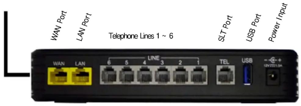
text_image
WAN Port LAN Port Telephone Lines 1 ~ 6 SLT Port USB Port Power Input WAN LAN 6 5 4 LINE 3 2 1 TEL USB UN TELMWPS Wireless Security Button
natural_image
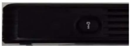
Close-up of a black electronic device with a key button (no visible text or symbols)The X-50 is extremely versatile in the way that it can be installed. It will work as a standalone small business telephone system with no connection to an existing Network or Internet...
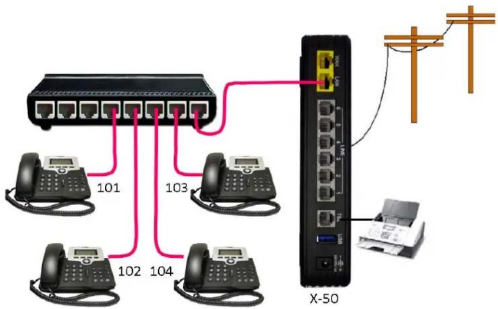
flowchart
graph TD
    A["Switch"] -->|101| B["Client Phone 101"]
    A -->|102| C["Client Phone 102"]
    A -->|103| D["Client Phone 103"]
    A -->|104| E["Client Phone 104"]
    A --> F["X-50"]
    F --> G["Printer"]
    style A fill:#f9f,stroke:#333
    style B fill:#ccf,stroke:#333
    style C fill:#ccf,stroke:#333
    style D fill:#ccf,stroke:#333
    style E fill:#ccf,stroke:#333
    style F fill:#cfc,stroke:#333
    style G fill:#fcc,stroke:#333
Connected to the Internet for email delivery and SIP Trunks ...
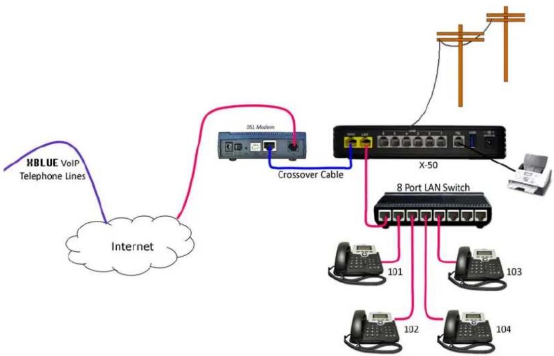
flowchart
graph TD
    A["HBLUE VoIP Telephone Lines"] --> B["Internet"]
    B --> C["Crossover Cable"]
    C --> D["X-50"]
    D --> E["8 Port LAN Switch"]
    E --> F["101"]
    E --> G["102"]
    E --> H["103"]
    E --> I["104"]
    D --> J["Telephone"]
    D --> K["Phone"]
or with a static IP Address connect remote workers or create a voice (campus) network...
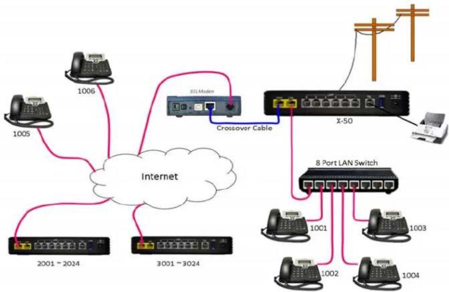
flowchart
graph TD
    A["1005"] --> B["Internet"]
    C["1006"] --> B
    D["2001~2024"] --> B
    E["3001~3024"] --> B
    B --> F["Crossover Cable"]
    F --> G["X-50"]
    G --> H["8 Port LAN Switch"]
    H --> I["1001"]
    H --> J["1002"]
    H --> K["1003"]
    H --> L["1004"]
    G --> M["Computer"]
    style B fill:#f9f,stroke:#333
    style H fill:#ccf,stroke:#333
And it can be connected together with nine additional X-50 systems creating a ten location voice communications network, also known as a "Campus Environment", each having up to 24 LAN or WAN SIP telephones endpoints.
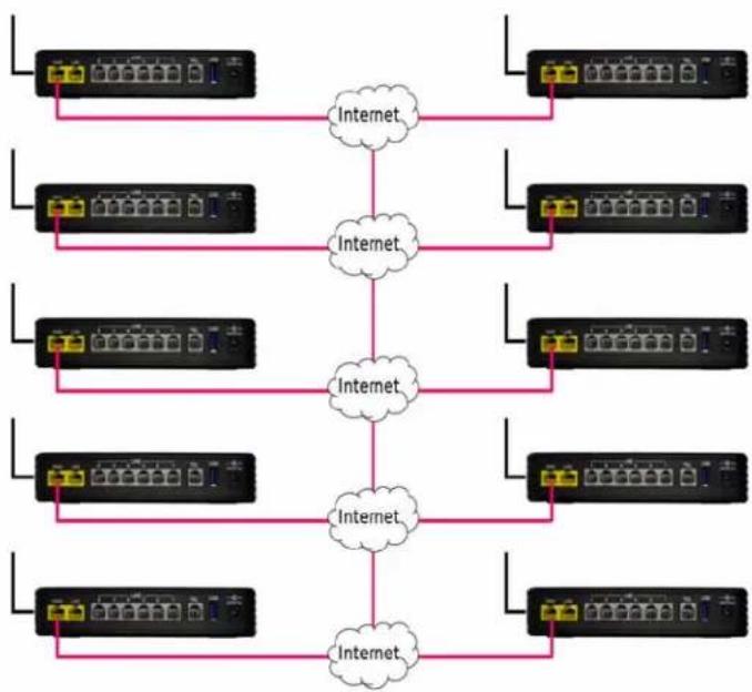
With a little networking knowledge, this system should be is easy to install and program.
Product Configuration
The X-50 IP small business system is a fully functional VoIP Telephone System, Auto (Receptionist) Attendant and Voice Mail as well as a full featured Internet Gateway (IGW). A Gateway is used to join two disparate networks such as a Local Area Network (LAN) and a Wide Area Network (WAN).
LAN vs. WAN
In reality a “Network” is nothing more than the “network of wires”, which is used to join computing devices. However, it has become common place to refer to the Local Area Network (LAN) as “the Network”, which includes computers, computer devices and peripheral equipment such as network printers. The Local Area Network is also referred to as “the Intranet” meaning the “Internal Network”. This manual may use these terms interchangeably.
The LAN port on the X-50 is used when installing endpoints, such as the X2020 telephone or other computer devices within the same Subnet, which is generally a small geographical area like a single building. The WAN port is used when connecting endpoints that are not within the same Subnet, which is generally a larger geographical area or remote location such as a home office.
LAN
A Local Area Network (LAN) or Intranet is created when two or more computing devices are connected together to share information or access to another device. A network switch, or multiple network switches, can be used when connecting more than two devices. The LAN port of a X-50 VoIP Telephone System is used to communicate with all of the connected devices and to connect these devices to other networks such as the PSTN or other WAN Devices.
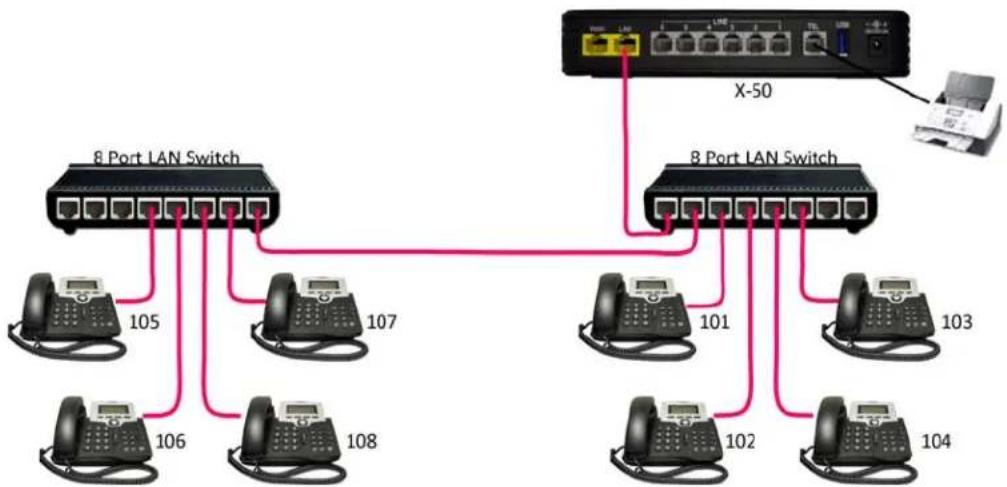
flowchart
graph TD
    A["8 Port LAN Switch"] -->|105| B["Phone 106"]
    A -->|106| C["Phone 107"]
    A -->|107| D["Phone 108"]
    A -->|101| E["Phone 102"]
    A -->|101| F["Phone 103"]
    A -->|102| G["Phone 104"]
    A -->|X-50| H["X-50"]
The X-50 routes calls over a standard Intranet using a TCP/IP backbone, and does not require or rely on the Internet.
Therefore, it is possible to use the X-50 as a standalone telephone system without connecting it to the Internet.
WAN
The WAN port is used when connecting a Gateway to the Internet Service Provider's (ISP) DSL/Cable modem. Once connected the Gateway allows remote devices to communicate with local devices connected to the LAN. Connecting the X-50 VoIP Telephone System to the ISP using a DHCP address allows SIP Trunks to authentication and other features such as email delivery of voicemail messages. This does not require a "Fixed" or Static Class A or B IP Address, just access to the Internet.
E-mail Delivery
When using SIP Trunks or e-mail delivery of a voice mail messages and not using remote worker or creating a voice network, the WAN port of the X-50 VoIP Telephone System is connected to a LAN port on the existing LAN. It can use a DHCP address or given an internal static IP Address.
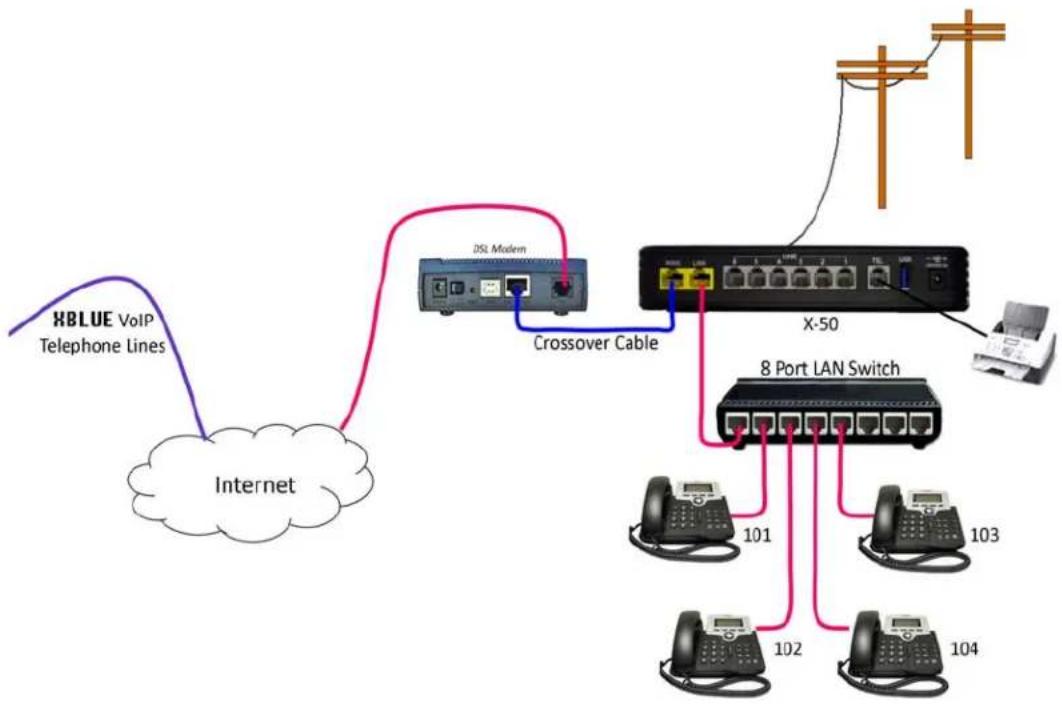
flowchart
graph TD
    A["HBLUE VoIP Telephone Lines"] --> B["Internet"]
    B --> C["DSL Modem"]
    C --> D["Crossover Cable"]
    D --> E["X-50"]
    E --> F["8 Port LAN Switch"]
    F --> G["101"]
    F --> H["102"]
    F --> I["103"]
    F --> J["104"]

What does that say?
The WAN port can be programmed so that it connects to the Local Area Network (LAN), allowing it to "function" as both a WAN and LAN port. This allows the administrator to use Network Address Translation (NAT) to redirect outside Class A or B IP Addresses to an internal locations.
Remote Telephones
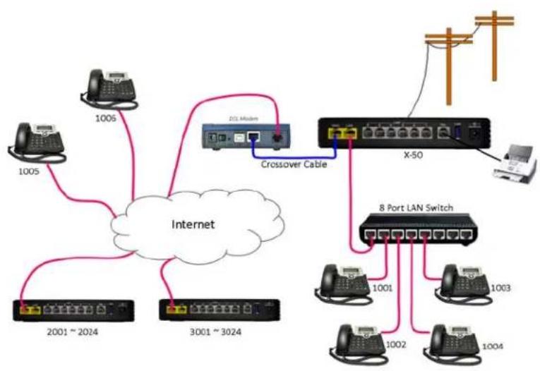
When connecting remote workers to the X-50 VoIP Telephone System it must have a fixed or static class A or B IP Address. When creating a voice network (Campus Environment) the "Master" X-50 VoIP Telephone System also must have a fixed or static class A or B IP Address. All other systems on the voice network can use Dynamic IP addresses. This may require the ISP's Gateway to be programmed as a Bridge or a concurrent bridge.
flowchart
graph TD
    A["1005"] --> B["Internet"]
    C["1005"] --> B
    D["1001 ~ 2024"] --> B
    E["3001 ~ 3024"] --> B
    F["DSL Midnet"] --> G["Crossover Cable"]
    G --> H["X-50"]
    H --> I["8 Port LAN Switch"]
    I --> J["1001"]
    I --> K["1002"]
    I --> L["1003"]
    I --> M["1004"]
    N["Telephone"] --> H
    O["Power Supply"] --> H
Remote telephones are directed to the static IP Address of the WAN port, which will have a Class A or Class B IP Address. Once registered, the WAN port of the X-50 keeps the telephone endpoints active by sending "keep alive" packets to each of the remote telephone endpoints.
The Remote telephone should set the Session Timer to 20 seconds.

What does that say?
The Internet Service Provider (ISP) will program their DSL/Cable modem to be a bridge or a concurrent bridge allowing the X-50 VoIP Telephone System to join the network parallel to the ISP's DSL/Cable modem. If needed, this also allows the X-50 VoIP Telephone System to become the main router on the Local Area Network (LAN).
When connecting remote workers to a X-50 system, it must have a static IP Address. When creating a voice network or "Campus Environment", only one of the X-50 systems must have a static IP Address.
Any H-50 with a static Class A or B IP Address will support remote workers, even if they are a node on a voice network.
Creating a Voice Network
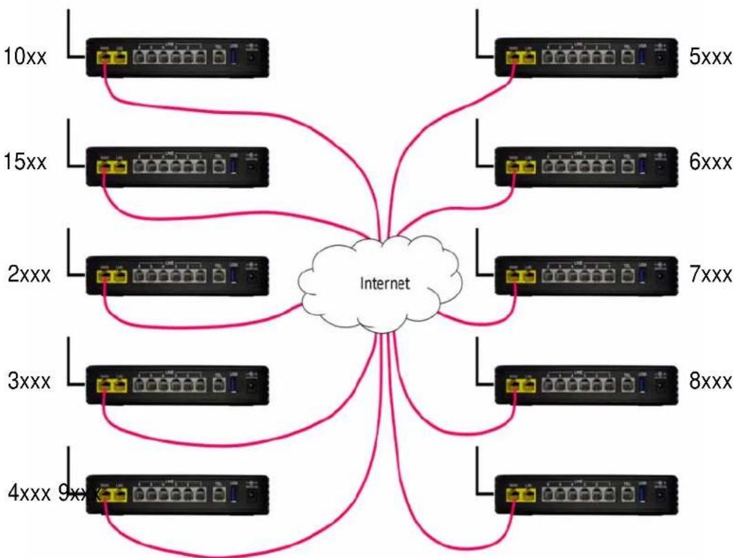
Using the Internet and the WAN port, it is possible to connect multiple X-50 systems together creating one large voice network “Campus Environment”, with 3 or 4 digit dialing between each location. To keep it cost effective, only one X-50 VoIP Telephone System requires a static Class A or B IP Address the rest can use DHCP Addresses. However, each location must have access to the Internet with enough bandwidth to support the number of calls to be processed. Creating this type of voice network requires a little preplanning to ensure that there enought bandwidth and no numbering conflicts.
Generally, it is a good idea to have a specific numbering sequence for each location. This can be as easy as routing specific groups of numbers, such as 100 to 149 for the “Master System”, 150 to 199 for the second location, 200 to 299 for the third location, etc., or when using 4 digit dialing the numbering plan may resemble 1000 to 1499 for the Master System, 1500 to 1999 for the second location, 2000 to 2999 for the third location, etc. Another option is to use a “leading Digit”, where the Master System is 1 + the extension number (1101, 1102, 1103, etc.), the second system is 2 + the extension number (2101, 2102, 2103, etc.), the third system is 3 + the extension number (3101, 3102, 3103, 3014, etc.).
flowchart
graph TD
    A["10xx"] --> B["Internet"]
    C["15xx"] --> B
    D["2xxx"] --> B
    E["3xxx"] --> B
    F["4xxx 9xx"] --> B
    G["5xxx"] --> B
    H["6xxx"] --> B
    I["7xxx"] --> B
    J["8xxx"] --> B
    B --> K["Internet"]
    style B fill:#f9f,stroke:#333
    style K fill:#ccf,stroke:#333
Things to know about the product
TABLE 2.1 Maximum Configuration
| PSTN SIP Trunk SIP Extensions | Single Line Analog Extension | ||
| 6 CO Lines 8 SIP Trunks | 24 SIP Extensions 1 | ||
| 14 Total Telephone Lines | 25 Total Extensions (24 SIP and 1 Analog) | ||
TABLE 2.2 Physical System Capacities
| Capacity Interface Port Description | |||
| 1 LAN RJ45 Local Area Network 10 | base-T/100 base-TX | ||
| 1 WAN RJ45 Wide Area Network (for remote workers or offices) | |||
| 10 base-t/100 base-TX/1000 base-T Gigabit Ethernet port | |||
| 1 FXS | RJ11 Connected a Single Line (Analog) Telephone or FAX | ||
| 6 FXO | RJ11 | Allowing 6 simultaneously Telephone Calls | |
| 1 USB | USB | USB Interface to create a network or centralized printer | |
| 1 Wireless | 802.x | LAN - 802.11a, 802.11b, 802.11g and 802.11n | |
| 24 | SIP | RJ45 SIP telephone endpoint devices | |
TABLE 2.3 System Software Capacities
| Capacity | Interface | Port | Description |
| 8 SIP Trunks | Interface with up to 8 SIP Trunks | ||
| 4 | AA & VM | Interfaces with Auto Attendant and Voice Mail with 32 hours of storage | |
| 24 | LAN/WAN | RJ45 Telephone Endpoints - Non Blocking | |
| 9 WAN RJ45 Additional Office to Office - Voice Network (total 10) | |||
| 14 | Concurrent Telephone Line Calls (PSTN and SIP Trunks) | ||
| 40 | Call Routing Tables | ||
| 25 | Voice mailboxes associated with a telephone endpoint | ||
| 40 | Virtual Mailbox Extension without telephone endpoint | ||
| 10 | Single Digit Dialing Menus with Menu Tree Routing | ||
| 10 | Day - Outgoing System Greeting (OGM) | ||
| 10 | Lunch (Noon) - Outgoing System Greeting (OGM) | ||
| 10 | Night - - Outgoing System Greeting (OGM) | ||
| 10 | Holiday - Outgoing System Greeting (OGM) | ||
| 10 | Temporary - Outgoing System Message (OGM) | ||
LED's on the X-50 System

text_image
POWER WIRELESS TEL 1 2 3 LINE 4 5 6 LAN WAN blueTABLE 2.4 LED Function
| LED Name LED Status Description | |||
| Power Blue On Power is On | |||
| Off Power is Off | |||
| Flashing | X-50is rebooting | ||
| Wireless Blue On Wireless LAN initialization | successful | ||
| Off Wireless LAN not operational | |||
| “TEL” Port SLT Telephone | Blue On Single | Line Telephone | is Busy |
| Off Single Line | Telephone is Idle | ||
| Line (1 - 6) Blue On PSTN Line is Busy | |||
| Off PSTN Line | s Idle | ||
| LAN | Blue On LAN is | Connected | |
| Off LAN is not | Connected | ||
| Blinking | Active LAN Traffic | ||
| WAN | Blue On WAN | Connected | |
| Off WAN is not | Connected | ||
| Blinking | Active WAN Traffic | ||
| Red | ON | Ping the Default Gateway fail or DHCP fail | |
Introduction
Notes:
2 System Specifications
TABLE 2.1 System Specification
| Feature | |
| Main Processor 400 MHz Dual Core MI | PS Processor Broadcom BCM6369 |
| Processor SDRAM External 64 MB | |
| Processor Flash ROM External 16 MB | |
| Supplementary Processor 1x DSP Mindspeed M82351 | |
| System Flash (Voice Mail) 512 MB | |
| Giga WAN PHY Chip Broadcom BCM5481 | |
| Standards IEEE 802.11 a/b/g/n, IEEE 802.3 | |
| Ports 1 - WAN, 1 - LAN, 1 FXS and 6 FXO | |
| Buttons Reset, WIFI On/Off and WPS | |
| Ports RJ-45 and RJ-11 | |
| LED's Power, Wireless, Telephone, Lines (6), LAN and WAN | |
| EMI/EMC | FCC Part 15 Class B |
TABLE 2.2 Environmental
| Operating Conditions | Specification |
| Operating Temperature | 32° F to 95 ° F |
| Storage Temperature | 32° F to 95 ° F |
| Operating Humidity | 10% to 80% - Non Condensing |
| Storage Temperature | 10% to 80% - Non Condensing |
| System Power | 12 Volts - 1.5A |
TABLE 2.3 IP PBX Configuration
| Quantity Interface Connector Description | ||||||
| 6 FXO RJ11 Allowing 6 simultaneously sessions | ||||||
| 1 FXS RJ11 For analog (single line) telephone | ||||||
| 1 | U | S | B | U | S | B |
| 1 LAN RJ45 10/100 Local Area Network | ||||||
| 1 WAN RJ45 100/1000 Wide Area Network (for remote workers or offices) | ||||||
TABLE 2.4 WiFi
| Connector | Speed | Port | Description |
| Wireless | 802.11 b, g and n | LAN Port | A Local Area Network allows network devices to share and access files through a wireless connection using 802.1x protocol. Generally, a LAN uses one DHCP Server, it is “small” in size (geographically) like a home or office, and it does not require any external ISP to transmit data between endpoints. |
| Antenna | 5dbi single pole | ||
TABLE 2.5 Default LAN and WAN Ports
| IP Address | Description | |
| LAN | 192.168.10.1 | Do not use IP Address 192.168.1.254 - it is reserved for the X-50's DSP. Using this port will result in erratic operation. |
| WAN | DHCP | The WAN port is set to DHCP and will connect to an existing network and can be set to DHCP, Static or PPPoE. |
TABLE 2.6 Physical Connectors
| Connector | Speed | Port | Description |
| RJ45 | 10/100/1000 BaseT | WAN Port | A Wide Area Network (WAN) allows devices to share and access files through a series of wires known as a “Network”. A WAN is used with multiple locations, and has no physical boundaries. It is actually possible to have a WAN that spans the globe. |
| RJ45 | 10/100 BaseT | LAN Port | A Local Area Network (LAN) allows network devices to share and access files through a series of wires known as a “Network”. Generally, a LAN uses one DHCP Server, it is “small” in size (geographically) like a home or office, and it does not require any external ISP to transmission data between endpoints. |
TABLE 2.7 X-50 System Capacities
| Capacity Interface Port Description | |||
| 6 FXO RJ11 Allowing 6 PSTN lines and simultaneously sessions | |||
| 1 FXS RJ11 Connected a Single Line (Analog) Telephone | |||
| 1 USB USB Connect a printer to be shared by devices on the LAN | |||
| 1 Wireless LAN LAN - 802.11b, 802.11g and 802.11n | |||
| 1 LAN RJ45 10/100 Local Area Network | |||
| 1 WAN RJ45 100/1000 Wide Area Network (for remote workers or offices) | |||
| 8 SIP Trunks Interface with up to 8 SIP Trunks | |||
| 4 | AA & VM | Interfaces with Auto Attendant and Voice Mail allowing it to process up to 4 simultaneous calls, which is shared with all telephone lines and endpoints | |
| 24 | LAN/WAN RJ45 Telephone Endpoints - Non Blocking | ||
| 10 | WAN RJ45 Office to Office - Voice Network (Campus Environment) | ||
| 14 | Concurrent Calls (Telephone Lines and SIP Trunks) | ||
| 40 | Call Routing Tables | ||
| 25 | Telephone Endpoint voice mailboxes with Personal OutGoing Message (OGM) | ||
| 40 | Virtual Voice mailboxes with personal OutGoing Message (OGM) | ||
| 10 | Single Digit Dialing Menus with Menu Tree Routing | ||
| 10 | Day time OutGoing Message (OGM) | ||
| 10 | Lunch (Noon) - OutGoing Message (OGM) | ||
| 10 | Night time OutGoing Message (OGM) | ||
| 10 | Holiday OutGoing Message (OGM) | ||
| 10 | Temporary Outing Message (OGM) | ||
TABLE 2.8 VoIP & Signalling Protocols
| Signaling | Documented Protocol | Description |
| G.168 | ITU-T G.168 | Echo Canceller was designed and used to address and standardize the performance of echo cancellers in the PSTN. |
| G.711 | ITU-T G.711 | Highest Bandwidth/Lowest Compression - best voice quality. A voice encoder that compresses 64K bit stream to an 8K per second sampling rate, with a typical algorithmic delay of 0.125ms. G.711 is used when transmitting Music, FAX'es and DTMF tones because it is very reliable. |
| G.723.1 | ITU-T G.723.1 | Intermediate Bandwidth/Intermediate Compression - minimal reduction in voice quality. A voice encoder that compresses voice in 30ms frames, with a look-ahead of 7.5ms, with a typical algorithmic delay of 37.5ms. G.729a uses very low bandwidth because it samples at 8kHz/16-bit (240 Samples for 30ms frames). |
| G.729.a/b | ITU-T G.729a | Lowest Bandwidth/Highest Compression and least complex protocol, with a hybrid speech reproduction quality by use of an Algebraic Code Excited Linear Predication (ACELP) that reproduces a voice encoder that compresses voice in 10ms frames, with a look ahead of 5ms per frame, and atypical algorithmic delay of 15ms, per frame. It operates at 8k bits, and can be used with 6.4kbits and 11.8k bits, with a marginal reduction in voice quality. |
TABLE 2.8 VoIP & Signalling Protocols
| Signaling | Documented Protocol | Description |
| In/out Band | RFC 2833 | In/Out Band is used to define the method of transporting DTMF tones to use on RTP connections. In-Band are tones that are “heard” by the distant party, and Out of Band tones are used for signaling. |
| MD5 RFC 3261 | Message-Digest Algorithm 5 - is a | widely used Cryptographic hash function (security) that uses 128 bit hash value. |
| QoS RFC 2990 | Quality of Service assigns different | priorities to different data packets. Voice, for example, will receive a much higher priority than non-voice traffic, so it receives the highest priority. Therefore, QoS is used to prioritize specific packets, such as voice, within a packet-switched network. However, it does not guarantee voice quality. |
| T.38 ITU-T T.38 | T.38 is the standard for transporting FAX transmissions, between G3 Fax devices, over an IP Network. | |
| RTP RFC 1889, 3 | 550 Real-time Transport Protocol | provides end-to-end network transport functions suitable for applications transmitting real-time data, such as audio, video, or simulation data, over multicast or unicast network servers. RTP is a standardize protocol for delivering audio and video over the Internet. |
| SDP RFC 2327 | Session Description Protocol is purely a protocol that negotiates between two endpoints to allow them to agree on a media type and format. It is intended for describing multimedia sessions, and to on a wide range of networks and networking environments. | |
| SIP V2 RFC 3261 | Session Initiated Protocol is an | applications layer control (signaling) protocol that is outlined in the “Internet Official Protocol Standards” document number RFC 3261. |
| ToS RFC 791, 10 | 60, 1122, 1123, 1195, 1247, 1248, 1349, 2474, 3168 | The Type of Service octet is part of the Internet Protocol header that specifies the priority of the attached datagram (message). |
| DTMF RFC 4733 | Dual Tone Multi-Frequency Tones - also known as touch tones® - Defined protocol for transmission of DTMF tones transmitted over a packet switching network. | |
| AF Class RFC 259 | 7 One part of QoS, is Assured Forwarding Classes. This allows the administrator to divide the IP Packets into one of 12 different Classes. In the event that the network becomes congested, the packets with the highest Drop rate will be dropped. | |
| EC | RFC 3246 Expedited Forwarding | has the characteristics of low delay, low loss, and low jitter, making it suitable for Voice, Video and other real-time services. |
TABLE 2.9 Internet Protocol
| Protocol Documentation Description | ||
| IP Address RFC 950 | Defines the standards used to divide Class A, B and C using Subnets. | |
| ARP | RFC 826, 3315 | Address Resolution Protocol - allows devices to find a “host” device using the network layer (MAC Address). |
| RARP RFC 903 | Reverse Address Resolution Protocol - allows devices to find a “host” device using the network layer (MAC Address). | |
| CHAP RFC 1994 | Challenge-Handshake Authentication Protocol - Negotiating protocol used with PPPoE. Also see MSCHAP and PAP | |
| MSCHAP | RFC 2433, 2759 | Microsoft’s version of CHAP that allows mutual authentication between peers, by piggybacking challenge and response packets on a successful packet. |
| PAP RFC 1334 | Simple method for the peer to establish its identity using a 2-way un-encrypted handshake. Passwords are sent in ASCII format with no encryption. Also see CHAP, and MSCHAP. | |
| DHCP Client | RFC 2131 - 2132 Dynamic Host | Configuration Protocol is used by client devices, to obtain the correct settings, when joining a network. |
| DHCP Server | RFC 2132 Dynamic Host Configuration Protocol is used by server devices, to obtain or assign the correct settings, when joining a network. | |
| DNS | RFC 1912 | A Domain Name System is the “Phone Book” for the Internet. It translates “Human Relatable” names such as www.xbluenetworks.com into the numeric IP Address. The DNS can be a local or remote server, and it is a essential part of today’s Internet. |
| HTTP | RFC 2616 | Hypertext Transfer Protocol - is one of the communications protocols used to transfer information over a packet-switched network, such as an Intranet or the Internet. Typically, HTTP (at default using port 80) initiates or receives a request/response from a client to/from a server. |
| ICMP | RFC 792 | Internet Control Message Protocol is one of the core protocols within Internet Protocol (IP). This protocol is a reactionary protocol only responding to error messages that are received. |
| IP | RFC 791 | Internet Protocol allows devices to communicate over a package-switched network. This protocol provides an unreliable network, and makes no guarantees about sending or receiving a data package; it is a “best Effort” protocol. Therefore, other protocols such as “TCP” were created to make data transfer more reliable. |
| NAT | RFC 3022 | Network Address Translation allows multiple hosts, on one private network, to access the Internet using one public IP Address. |
| NAPT | RFC 2663 | Network Address Port Translation increases the efficiency of NAT by translating the “transport identifier”, allowing a private host to multiplex into the transport identifiers to appear as a single Public IP Address. |
| PPPoE | RFC 2516 | Point to Point over Ethernet allows users to “Virtually” create a direct connection between two devices over an Ethernet network. |
| SNTP | RFC 1305 | Simple Network Time Protocol allows devices packet-switched networks to synchronize their time from a specific location. |
| NPT | RFC 867, 868 | Network Time Protocol ensures that the time is synchronized all along the Packet Switching Network. |
| TCP | RFC 793 | Transmission Control Protocol provides the reliability that Internet Protocol (IP) does not, making it suitable for applications such as File Transfer and E-mail. |
TABLE 2.9 Internet Protocol
| Protocol Documentation Description | ||
| Telnet RFC 2946 | TELNET is a reliable connection | oriented transport protocol, which is Client/Server based. At default TELNET uses Port 23. |
| TFTP RFC 2349 | Trivial File Transfer Protocol is a | very basic and simple protocol which is loosely based on the FTP protocol. |
| UDP FRC 768 Using User Datagram Protocol network | Working computers can send short messages known as datagrams. Although the delivery of a UDP packet is faster it is not as reliable as TCP packets. | |
| RIP v1, v2 | RFC 1058, 2453 | Routing Information Protocol used in Local and Wide Area Networks to limit the number of hops allowed in a path from source to destination. Maximum number is 15 hops. |
| CLIP Calling Line | Identification Presentation | |
System Feature Description Table
TABLE 3.1 VoIP Module Features
| Feature Page Feature Page | |||
| Access Control | page 31 | Least Cost Routing (Call Routing) | page 38 |
| Account Codes (Traveling COS) | page 31 | Line Group Assignment | page 39 |
| Alarm (Station) | page 31 | Live Call Record | page 39 |
| Alternate Attendant | page 31 | Meet Me Page | page 39 |
| Announcement Mailbox | page 31 | Message Waiting Indication | page 39 |
| Answer Position | page 32 | Music on Hold | page 39 |
| Automated Attendant (Receptionist) | page 32 | Mutual Mailboxes (Group Mailbox) | page 39 |
| Automatic Daylight Savings (Internet) | page 32 | Navigation Keys (Buttons) | page 39 |
| Automatic Hold | page 32 | Night Service (Automatic day/night) | page 40 |
| Automatic Line Select | page 33 | Numbering Plan | page 38 |
| Automatic Provisioning (PnP) | page 33 | Off Hook Preference | page 40 |
| Automatic Route Select (Call Routing) | page 33 | Outgoing Call | page 40 |
| Backlit Display | page 33 | One Touch Record | page 40 |
| Basic Calling | page 33 | Paging (All Call and Zone) | page 40 |
| Busy Call Back | page 33 | Pause | page 41 |
| Busy Lamp Field (Busy Extension) | page 33 | Phantom Mailbox (Extension) | page 41 |
| Call Abandon | page 33 | Phonebook (Personal) | page 41 |
| Call Forwarding (6 types) | page 34 | Phonebook (Public) | page 41 |
| Call Operator | page 34 | Power Fail Transfer | page 41 |
| Call Park | page 34 | Programmable Buttons (Telephone & Sidecar) | page 41 |
| Call Pickup - Group | page 35 | Redial | page 41 |
| Call Restriction | page 35 | Registration Server | page 42 |
| Call Routing | page 35 | Remote (Administration) Management | page 42 |
| Call Waiting | page 35 | Service Mode | page 42 |
| Caller ID | page 35 | SIP IP Trunk (Maximum 8) | page 42 |
| Class of Service | page 35 | Soft (Interactive) Keys | page 42 |
| Conference | page 36 | Speed Dial | page 42 |
| Day & Night Service Mode | page 36 | Station Lock | page 42 |
| Daylight Savings Time | page 36 | Station Message Detailed Recording | page 43 |
TABLE 3.1 VoIP Module Features
| Feature | Page | Feature | Page |
| Default Setting | page 36 | System Speed Dial | page 42 |
| Direct Inward Dial | page 36 | System Time & Date | page 43 |
| Direct Inward System Access | page 36 | Time and Date in Display | page 43 |
| Distinctive Ringing | page 37 | Toll Restriction | page 43 |
| DNS Client | page 37 | Transfer | page 43 |
| Emergency Call | page 37 | ||
| Extension Password | page 37 | Traveling Class of Service | page 43 |
| E-mail Delivery of Voicemail Messages | page 37 | Trunk Group | page 43 |
| FAX Detection | page 37 | Uniform Distribution/Hung Group (UCD) | page 44 |
| Flexible Numbering Plan | page 38 | UCD - Agent Login/Logout Call Reroute | page 44 |
| X-50 to X-50 | page 38 | Virtual Mailbox (Extension) | page 44 |
| Hot Dial Keypad | page 38 | Voice Mail | page 44 |
| Last Number Redial | page 38 | Wizard Setup | page 45 |

Access Control - Browser
For security, the X-50 is password protected with a programmable port, making it more secure. There are three different password levels, User, Administrator, and Support.
TABLE 3.2 Password levels
| User Name Password Description | ||
| admin2583 000000 | Unrestricted access to all programming parameters | |
| user user View config | guration settings and statistics | |
| support support Run | Diagnostics with technical support engineer on the phone | |
Only one Administrator can log into the X-50 at one time. Additional attempts to enter the administration area will be denied until the original administrator has exited and three minutes have elapses.
Account Code
Also known as “Traveling Class of Service” - This allows authorized users to make calls on restricted extensions. The systems recognizes the user when they enter a code and their password, and brings their less restrictive class of service to the new location. The user’s Class of Service remains active for 60 seconds after the call is disconnected and then it returns to the original Class of Service.
Agent (UCD) Logon/Logoff
Agents (extensions) may dial a code, which temporarily takes them out of all UCD groups. Once the agent logs off, they will not receive any additional incoming UCD calls. This can be very helpful when an agent is out of the office or out to lunch. When the agent returns, they dial a code to log into all UCD groups. Once logged in, they start receiving UCD calls.
Alarm
Each X2020 connected to the X-50 VoIP Telephone System can set up to three telephone alarms, which can be programmed to play once or set to always. The user can select between 11 (0\~10) different ring tones. After the alarm is reached, it can repeat up to 10 times at an interval of once every 1 to 5 minutes.
Alternate Attendant
A second extension may be programmed as the Alternate Attendant. The alternate answering position serves as a back up position to the primary attendant. Telephone line ringing will forward to the alternate answering position after the preprogrammed ring alternate position time.
Announcement Only Mailbox
Any physical or virtual voice mailbox can be programmed to be an announcement only mailbox. An announcement only mailbox may be used to make common announcements such as business hours, directions, mass schedules for Church, etc. These mailboxes can be accessed from the Automated Attendant or the Attendant can transfer a call directly to the announcement. After the announcement plays the call is disconnected.
Answer Position
Each of the six analog (PSTN) and eight SIP trunk lines can be programmed to ring at the Operator, Auto Attendant, Extension or UCD hunt group for both day and night. When set to operator - callers will ring the extension that is programmed as the operator in the system. When set to auto attendant - callers will ring one of the four auto attendant ports and be answered with the appropriate day, lunch, night, holiday or temporary outgoing message. When set to Extension - callers will ring the entered extension. When set to Universal Call Distribution (UCD) Group - all members of the group (up to 25 members can be entered into each group) will ring.
Automated Attendant (Receptionist) (AA)
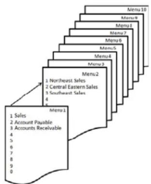
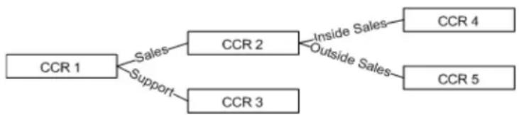
The system comes standard with an integrated four port Automated Attendant (Receptionist) which can perform up to four simultaneous tasks. All telephone lines, extensions and virtual mailboxes share these four ports. When the Answer Position, for a telephone line, is set to "Automated Attendant" the call is immediately answered and is played a customizable prompt. In addition, there are 10 single digit dialing menus that can be used to route callers. Each menu has the ability to play five; day, lunch, night, holiday and temporary outgoing messages (OGM) based on the time of day or day of week. The X-50 VoIP Telephone System also supports single digital dialing and menu trees.
flowchart
graph TD
    A["Menu1"] --> B["1 Northeast Sales"]
    A --> C["2 Central Eastern Sales"]
    A --> D["3 Southeast Sales"]
    A --> E["4"]
    A --> F["5"]
    A --> G["6"]
    A --> H["7"]
    A --> I["8"]
    A --> J["9"]
    A --> K["0"]
    style A fill:#f9f,stroke:#333
    style B fill:#ccf,stroke:#333
    style C fill:#ccf,stroke:#333
    style D fill:#ccf,stroke:#333
    style E fill:#ccf,stroke:#333
    style F fill:#ccf,stroke:#333
    style G fill:#ccf,stroke:#333
    style H fill:#ccf,stroke:#333
    style I fill:#ccf,stroke:#333
    style J fill:#ccf,stroke:#333
    style K fill:#ccf,stroke:#333
    style L fill:#ccf,stroke:#333
    style M fill:#ccf,stroke:#333
    style N fill:#ccf,stroke:#333
    style O fill:#ccf,stroke:#333
    style P fill:#ccf,stroke:#333
    style Q fill:#ccf,stroke:#333
    style R fill:#ccf,stroke:#333
    style S fill:#ccf,stroke:#333
    style T fill:#ccf,stroke:#333
    style U fill:#ccf,stroke:#333
    style V fill:#ccf,stroke:#333
    style W fill:#ccf,stroke:#333
    style X fill:#ccf,stroke:#333
    style Y fill:#ccf,stroke:#333
    style Z fill:#ccf,stroke:#333
flowchart
graph TD
    A["CCR 1"] -->|Sales| B["CCR 2"]
    A -->|Support| C["CCR 3"]
    B -->|Inside Sales| D["CCR 4"]
    B -->|Outside Sales| E["CCR 5"]
Automatic Daylight Savings (NTP)
When the X-50 VoIP Telephone System is connected to the Internet it will automatically synchronize the date and time using Network Time Protocol (NTP). Therefore, when time changes for daylight savings, the system will automatically change.
Automatic Hold
Automatic hold allows extension users to press a preprogrammed extension button (DSS) to announce a call without pressing hold first. The telephone line call is automatically placed on hold. This allows busy extension users, such as the attendant, to answer multiple calls very quickly.
Automatic Line Select (Hot Line)
Users may select how their idle extension functions when lifting the handset or pressing the speaker button. An extension can be set to access a specific outside line, a line group, or intercom (ICM) automatically when going off hook or pressing the speaker button. In addition, Users can program a timer from 0 to 8 second, delay before the off hook action is taken.
Automatic Provisioning
The system comes standard with WAN Management Protocol (TR-069) which allows the system to use Auto-Configuration Server (ACS) to preform auto-configuration, provision, collection, and diagnostics.
Automatic Route Select (ARS)
See Call Routing
Backlit Display
The X2020 SIP Telephone endpoint has a 6 line, 128 x 64 backlit display, which can be programmed go into sleep mode, or stay lit.
Basic Calling
There are two different types of calling; Intercom which are calls within the system and telephone line to an external location. When a dialed number is within the system numbering plan, it is considered an intercom call. If the number is not within the system numbering plan, but matches an entry in the routing tables the call will be routed over the appropriate telephone line or line group. Related Features: Numbering Plan and Call Routing.
Busy Call Back
Busy Call Back allows the user to dial a code when they call a busy extension to queue up for a call. When the called extension hangs up, the calling extension will ring, when calling extension lifts the handset, the called extension will being ringing.
Busy Lamp Field (BLF)
Busy Lamp Field also known as Direct Station Select (DSS) is a visual indication, usually a LED on a preprogrammed button, that shows when an extension or telephone is busy. The associated LED will be lit solid indicating that the extension or telephone line is busy.
Call Abandon
Call Abandon is a timed signal which is sent from the telephone company to the system to indicate that a telephone line had disconnected. This is especially helpful when callers disconnect the call while they are on hold. The system receives a timed disconnect signal, which matches the preprogrammed Call Abandon Time, from the telephone line provider and forces the telephone line on-hook.
Call Forward
At default, all extensions are forwarded to voicemail. However, they can also use several other types of call forwarding; Busy, Direct, Do Not Disturb, Follow me, Call forking, and Remote (External). These can be programmed using the web interface or by dialing the call forward code.
Busy Call Forward
Busy Call Forward, forwards all incoming calls to the forwarded destination only when the extension is busy. Extensions that are busy forwarded will not ring when a second call is presented to them. However, an alert tone is heard indicating that a new call is being routed to the forwarded destination.
Direct (Always) Call Forward
Direct Call Forward, forwards all incoming calls to the forwarded destination as soon as it is presented to the extension. An alert tone is heard indicating that a new call is being routed to the forwarded destination.
Do not Disturb Call Forward
DND call forward, forwards all incoming calls to the forwarded destination only when the extension is in DND. If the extension is put into DND and it is not DND forwarding, callers will get a busy signal.
Follow me Forward
The Follow Me Forward, feature allows internal extension users to re-forward their extensions to a new location. This is especially helpful when waiting for an important telephone call but must go to another destination, such as an impromptu meeting. An alert tone is heard indicating that a new call is being routed to the forwarded destination.
Call Forking Forwarding
Call Forking is used to ring two destinations at the same time. This feature will work for two extension number, without a SIP Trunk, but with a SIP Trunk, it can ring an extension and one or two external numbers.
Remote (External) Call Forward
Remote (External) Call Forward, allows extension users to forward their incoming calls to a remote destination such as a cellular or home telephone number. The extension user can change their forwarded destination from their extension.
Call Operator
The system supports both a primary and secondary operator which can be accessed from any SIP telephone endpoint or the analog port by dialing "0". Any extension, SIP telephone endpoint or FXS (analog port) can be assigned as the primary and secondary operator. The Operators are defined in the Numbering Plan.
Call Park
Park often called orbit, is a way of placing a call on hold where anyone within the system can access that call by dialing a park pickup code. The Park location is usually the same as the extension number.
Call Pickup Group
Any extension SIP telephone endpoint can dial star “*” to pick up a telephone line that is ringing at a different extension. If multiple telephone lines are ringing the oldest ringing line will be accessed.
Call Restriction
When making a telephone line call all digits dialed will be compared to the telephone's Class of Service and restriction table. The Call Restriction table allows the administrator to enter a range of digits (From - To), Trunk Access, Class of Service (COS). The X-50 VoIP Telephone System has eight classes of service zero (0) which has no restrictions and seven which is the most restrictive. The Call Restriction Table is made up of two tables an allow table and a deny table. Each entry into either table is associated with a Class of Server. The combination of these entries make up the allow or deny table. There are 40 call restriction tables and they work in the following way:
- If there are no entries in either the allow or deny tables, all calls are allowed. If there are entries in either table the calls are evaluated in the following order:
- Deny Table - If the dialed digits match an entry in the deny table the call is denied. If the dialed digits do not match an entry in the deny table, the call is sent to the allow table.
- Allow Table - If the digits match an entry in the allow table, the call is allowed. If the digits do not match an entry in the allow table, the call is denied.
Call Routing
When making a call all digits dialed will be compared to the rules entered in the Call Routing Table. The Call Routing Table is built using up to 40 different routing rules. Each call routing condition (rule) directs the dialed digits to a specific route and is made up of eight parameters, which include the "From" and "To" dialed digits, "Minimum" and "Maximum" number of digits to evaluate, number of digits to "Delete" or "Insert" before dialing the numbers over the "Destination" route (line group).
The call routing table is used to route calls over a voice network, which allows the administrator to route calls the most inexpensive way. For example, in a voice network with locations in Boston, Chicago, and San Francisco calls with a 617 area code, can be routed to the Boston location, thus avoiding toll charges.
Call Waiting
The Call Waiting Flash supports the CO line flash, which allows extension users to pick up a call after receiving a call waiting indication from the telephone line provider.
Caller ID
The system is equipped to received caller ID (requires a subscription) from the telephone line provider and will at default passed the information to a ringing telephone (SIP or Analog) extension.
Class of Service
Each extension in the system is assigned one day and one night class of service of service, which determines the extension's dialing privileges. There are eight different Classes of Service which are defined in the Call Restriction Table. A Class of Service (COS) of seven has the most restriction whereas a COS of zero (0) has no restrictions.
Conference
The systems can conference, join together, multiple Telephone (PSTN or SIP) Lines or extensions, or a combination of both, to the maximum of three connections so that multiple parties can speak together simultaneously.
Day & Night Service Mode
The system can run in either day or night mode and can be programmed to automatically switch between day and night mode.
Daylight Savings
The system supports manual or automatic synchronization of daylight savings. When set to automatic the system will automatically change from standard to daylight savings time. When set to manual, the administrator will have to enter the update manually.
Default Setting
Using the “Restore Default” feature found in “Management” the administrator can reset the system back to factory default. This will also reset some of the SIP Telephone endpoint parameters such as Line Keys, Call Forward Settings, Auto Answer, Phone Lock and Call waiting. However, it does not reset any system prompts that have been rerecorded.
Direct Inward Dial (DID)
Using the SIP Trunks, the system can support up to 50 Direct Inward Dial (DID) numbers. These numbers share with the connected (up to eight) SIP trunk positions. The system has a special DID Ring Table which allows the administrator to direct the incoming DID numbers to a specific extension, Auto Attendant, UCD group or voice mailbox. In addition, some DID can also be programming as Direct Outing Dialing (DOD) which can be programmed to send the DID number as its caller ID.
Direct Inward System Access (DISA)
DISA allows an incoming caller to enter a code into the auto attendant to gain access to system resources. At default this feature is disabled. Enabling this feature could cause unwanted long distance charges, which are the sole responsibility of the owner of the system.
Direct Telephone Line Access
Each extension can program any programmable button to be a direct access to a PSTN or SIP Trunk telephone line.
Distinctive Ringing
Telephone Line
Each telephone line (PSTN or SIP Trunk) can be programmed to ring with one of eleven different ring tones.
Extension
Each SIP Telephone endpoint can be programmed to ring with one of eleven different ring tones.
Domain Name Server (DNS)
A Domain Name Server is the "Phone Book" for the Internet. It translates "Human Relatable" names such as www.google.com from the numeric IP Address 64.233.187.99. The DNS can be a local or remote server, and it is a essential part of the Internet.
Emergency Call
The system, regardless of Class of Service, Call Routing, Call Restriction or Phone Lock programming, will not block any of the five emergency numbers that are programmed into the Emergency Call Table. At default, 911 is programmed into the table.
Note:
Numbers in the Emergency Call table cannot conflict with any numbers in the numbering plan. For example, when using 3 digit extension numbers do not use “911” as one of the extensions.
Extension Password
All extensions in the system are assigned a password that is used to access voice mail and when using the phone lock/unlock feature.
E-mail Delivery of Voicemail Messages
The voice mail has the ability to send a new voice mail message to a users E-mail address. The systems uses Simple Mail Transport Protocol (SMTP) to send the voice mail message as a standard WAV file, which can be reviewed by most smart phones or multimedia Personal Computers.
FAX/Modem Detection
The X-50 supports both FAX (T.38) and Modem detection and auto-fallback to G711, from an analog telephone line to the Single Line Port.
Flash
The Flash key (or hook switch) on an analog telephone (Single Line Telephone) connected to the system can be used to activate features such as placing a call on hold, picking up the held call, or when transferring a call to another destination.
Flexible Numbering Plan
The X-50 is preprogrammed with a default numbering plan which may be changed to suit customers' needs. When changing the numbering plan it is important to remember that the numbers entered cannot conflict with the numbers entered in the Emergency Call Table.
TABLE 3.3 Default Numbering Plan
| Description Default Numbers Configure | ||
| Start extension number 101 | ||
| End extension number 125 | ||
| FXS Phone Extension 125 | ||
| Operator speed-dial number 0 Day/Night Alternate Day/Night | ||
| AA/Voicemail Service Number 450 | ||
| Start Virtual Extension Number 830 | ||
| Start PSTN Line number 701 | ||
| Start IP Trunk Line Number 711 | ||
| Start Trunk Group Number 80 | ||
| All Paging number | 400 | |
| All Paging Range | LAN/WAN/Both | |
| Paging Group Start Number | 401 | (1) 401, (2) 402, (3) 403 |
| UCD Group Start Number | 430 | (1) 430, (2) 431, (3) 432, (4) 433 |
| System Speed Dial | 600 | 600 through 699 |
| Start Call Park Number | 731 | |
X-50 to X-50
Each X-50 VoIP Telephone System can be one of ten systems that creates a voice network. Once connected, extensions will be able to dial directly to extensions on the network. For example, if an extension (111) in Boston wanted to call an extension (211) in San Francisco they would dial 211. In the call routing table 211 will be directed to the San Francisco Gateway and the call will be connected. Similarly, telephone line calls can be routed to remote gateways for cost effective call processing.
Hot Dial Keypad
The H2020 telephone endpoints support hot dial keypad dialing, which allows a user to dial a telephone number without lifting the handset or pressing the speaker button.
Last Number Redial
Last Number Redial also known as Redial is used to press one button for quick access to the last thirty numbers dialed from that extension.
Least Cost Routing
See Call Routing
Line Group
Each telephone line in the X-50 is assigned to one of four line or trunk groups, which are used to group similar trunks together. For example, all PSTN lines in group 1 and SIP trunks in group 2, etc.
Live Call Record
Also known as One Touch Record feature, which allows extension users to record the current conversation. Live Call Record is extremely helpful for remembering telephone numbers or addresses when a pen and paper are not readily available. The recording is placed in the user's personal mailbox so that they may listen at a more convenient time. This feature works with local (LAN) and remote (WAN) authenticated X2020 telephones.
This feature may violate privacy laws if used in a manner that is inconsistent with requirements of these laws. Manufacturer assumes no responsibility with regard to the use of this feature. It is provided for the virtue of ethical use only. The User is responsible for using this feature appropriately considering all applicable laws.
Meet Me Page
Meet me page allows an extension user to dial a code from any extension within the system and be connected to the person that just completed a page. Once the call is established the paging port is released, and the two parties will converse privately.
Message Waiting Indication (MWI)
Whenever a new voice mail message is left of for a SIP telephone endpoint the light bar above the LCD Display will flash rapidly and the display will update to indicate that there is a message.
Music on Hold
The system has a prerecorded music on hold file that plays whenever a telephone line or SIP trunks is placed on hold.
Mutual Mailboxes (Group Mailbox)
A Mutual Mailbox is a special mailbox that can appear on multiple telephone extensions. This allows a group of extension users to share access to the same mailbox. When a new message is left in the mailbox, all extensions with the special mailbox button will light, indicating that there is a new voicemail message.
Navigation Keys
The X2020 come equipped with "cell phone like" navigation keys, which are used to scroll through features, lists and programming parameters. They allow the user to go up, down, left, right, and the center key is used to select, say OK, or confirm the parameter entry.
Night Service
The X-50 VoIP Telephone System can operate in two modes; day service and night service. Night service can be used to change the extension Class of Service as well as the system ring scheme and Auto Attendant message. Each extension is assigned a day and a night class of service, which can be used to specify day and night dialing privileges. Thus, controlling the amount of unauthorized calls placed at night.
Numbering Plan
See Flexible Numbering Plan
Off Hook Preference
Similar to Automatic Line Select and Hot Line, The analog (SLT) telephone and X2020 extension users have the ability to select how their telephone will react when they lift the handset or press the speaker button. For example, the telephone can access a specific telephone line, line group, dial a specific or group of extensions, and even dial an outside telephone number.
Outside Calls
Once authenticated, an X2020 telephone can dial a telephone number without going off hook, pressing the speaker button, or accessing a telephone line. In addition, the user can press the softkey under "Backsp" to delete a number if it is dialed incorrectly. Once the "Dial Time-out" timer expires, or the user presses the center navigation button (Check Button" the call is sent to the X-50 for processing. The user can also press a preprogrammed telephone line button and dial the number directly.
One Touch Record
Also Known as Live Call Record - Extensions have the ability record the current conversation. One Touch record is extremely helpful for remembering telephone numbers or addresses when a pen and paper are not readily available. The recording is placed in the user's personal mailbox so that they may listen at a more convenient time. This feature works with local (LAN) and remote (WAN) authenticated X2020 telephones.
This feature may violate privacy laws if used in a manner that is inconsistent with requirements of these laws. Manufacturer assumes no responsibility with regard to the use of this feature. It is provided for the virtue of ethical use only. The User is responsible for using this feature appropriately considering all applicable laws.
Paging
All Call Page
When doing an all call page, all LAN and WAN H2020 telephones (within the same subnet) that are idle will receive the page announcement.
Zone Page
Each extension can be placed into one or more paging zones. This allows specific areas to make a page announcement without interrupting everyone on the system. When the page zone is dialed, all LAN and WAN H2020 telephones (within the same subnet) that are idle will receive the page announcement.
Pause Insertion
Pause is a momentary delay in dialing when placing an outgoing PSTN or SIP Trunk Line from a stored number such as a speed bin. In addition, the X-50 system will automatically enter a momentary pause when an international number is dialed. To insert a Pause when programming a speed dial bin, use either a "P" or "p".
Phantom Mailbox (Extension)
The X-50 VoIP Telephone System has 40 special phantom or virtual mailbox extensions. They are used for personnel that do not require a physical telephone but need to be visible within the system. They can also be used as group mailboxes allowing multiple people to share the same mailbox.
Phonebook
There are two types of phonebook, Personal and Public. The Personal Phonebook is for the private use of the user that enters the number and the Public Phonebook can be accessed by all authenticated X2020 telephones.
Private
Each extension has a phonebook for their exclusive use. The phonebook holds 200 numbers that are stored alphabetically by the name and can be grouped by Family, Friends, Colleague, and VIP. In addition, if incoming Caller ID matches one of these entries, they can be assigned to use a distinctive ringing tone.
Public
The Public Phonebook is a list that the administrator creates and maintains in a centralized location allowing all authenticated X2020 telephones to link to the list. Each user has the ability to import the list and have access to the numbers.
Power Failure Transfer
In the event of a power failure, the first PSTN line will be automatically connected to the FXS port labeled "TEL" in the system.
Programmable Buttons
Each X2020 telephone has the ability to program the four button labeled 1, 2 3 and 4. At default, they are the first four PSTN telephone lines and the optional Sidecar has twenty-four (24) buttons which at default are extensions 101 through 125. Any of the buttons on the phone or the sidecar can be programmed to be feature, telephone line, speed bin, etc.
Redial
Redial also known as Last Number Redial is used to press one button for quick access to the last thirty numbers dialed from that extension.
Registration Server
The X-50 VoIP Telephone System acts like a registrar server for both SIP telephone endpoints and SIP trunks, which eliminates any possibility of a numbering conflict.
Remote Management
The X-50 VoIP Telephone System combines both Proxy and Registrar servers in its application. For a Registrar server, it acts as the front end to the location service for a domain, reading and writing mappings based on the contents of the Register requests. The location service is then typically constructed by a proxy server.
Service Mode
There are three service modes; Day, Night and Time. When the system is in day mode, the day greeting will play and the day class of service will be referenced when an extensions dials a number. Night mode, the night greeting will play and the night class of service will be referenced when an extension dials a number. If the system is set to Time mode, it will automatically switch between day and night modes and the associated classes of service, day and night.
SIP Trunk
The system can support up to 8 SIP uplink servers, known as SIP Trunks. These trunks, once authenticated, are treated as any other trunk (telephone line) in the system. In addition, to the normal programming such as Answer Position, Call Routing, Call Restriction, and Trunk Groups, the X-50 also supports provisioning for Direct Inward Dial (DID) numbers over SIP trunks. SIP Trunks are also required when using the Call Forward feature Forking.
Soft Interactive Keys
There are four buttons under the X2020 telephone display that change their function, to assist the user, as they use the telephone. For example, when the phone is idle, the left soft key shows "Menu", which changes when the speaker button is pressed to "NUM" and the third key shows "SPD".
Speed Dial
The X2020 telephone has a special location with quick access for frequently dialed numbers. Unlike the Phonebook, these numbers are stored by location number 0\~9 and can be accessed by pressing the down navigation key from an idle telephone.
Station Lock
Using an extension's password, users can lock their telephones. This helps reduce unauthorized users from using an extension that may have an unrestricted toll restriction. The use of station lock, may cause that extension to be restricted from calling 911!
Station Message Detailed Recording (SMDR)
This feature is used to monitor and report on incoming and/or outgoing telephone line (PSTN or SIP Trunk) calls and displays it chronologically by extension number. The SMDR information stores telephone line used, extension number, time and date, and the length of each call.
System Speed Dial
See Phonebook Public
System Time and Date
When connected to the Internet the system uses Network Time Protocol (NTP) to synchronize the time and date. In addition, the date and time can be set manually.
Time and Date in Display
The first line on the LCD of an idle X2020 telephone shows the date and time. The Time format can be changed from the default, "USA Time 12 Hour" to "USA Time 24 Hour" or "European 12 and 24 Hour" format. When using the European format, the date will also change, after 1 minute, from MM/DD/YY to DD/MM/YY format.
Toll Restriction
The Call Restriction Table is used to define up to eight different classes of service which is used by both SIP telephone endpoints and SIP trunks. The Call Restriction Table is built “created” by using up to 40 different allow tables. Each table uses a “from” digit and a “to” digit to define the approved digits. If a number is dialed that is not between the “from” and the “to” digits, the call is denied and will not be placed.
Transfer
Calls that are answered by a SIP telephone endpoint may be transferred to another destination, such as a different extension, voicemail or an extension on another system within the voice network.
Traveling Class of Service
Also known as “Account Codes” - This allows authorized users to make calls on restricted extensions. The systems recognizes the user when they enter a code and their password, and brings their less restrictive class of service to the new location. The user’s Class of Service remains active for 60 seconds after the call is disconnected and then it returns to the original Class of Service.
Trunk Group
All trunks are automatically placed into one of four trunk groups, which are used to group trunks (PSTN or SIP) with "like" programming such a local and long distance.
Unified Call Distribution (UDC) or Hunt Group
The system has four Uniformed Call Distribution (UCD) Groups (Hunt Groups), each can support up to 25 extensions. Each UCD can be programmed as an all ring, linear or distributive ring group and if unanswered calls can be rerouted to another destination such as a different menu and greeting, or directly to a voice mailbox.
- All Ring - Rings all extensions simultaneously
- Linear - The call is placed into queue and the system attempts to ring the first programmed member, if that member is busy, the next programmed extension is tired. If that one is busy, the third programmed member is tried and so on.
- Distributive - The call is placed into queue and the system finds the agent that is on-hook and idle the longest, and rings that member first.
UCD Agent Logon and Logoff
Agents (extensions) may dial a code, which temporarily takes them out of all UCD groups. Once the agent logs off, they will not receive any additional incoming UCD calls. This can be very helpful when an agent is out of the office or out to lunch. When the agent returns, they dial a code to log into all UCD groups. Once logged in, they start receiving UCD calls.
UCD Reroute
All UCD groups have the ability to reroute unanswered calls to a Menu, Voicemail, Phone or Virtual Extension. In addition, a voice mailbox can be set to be an announcement only so that it plays a message to the caller and then disconnects the call.
Virtual Extension (Phantom)
The X-50 VoIP Telephone System has 40 special virtual mailbox or phantom extensions. They are used for personnel that do not require a physical telephone but need to be visible within the system. They can also be used as group mailboxes allowing multiple people to share the same mailbox.
Voice Mail
The system has an integrated Auto Attendant and voice mail system with 32 hours of message storage. Each authenticated extension, plus any virtual extension, has access to a password protected voice mailbox. For extensions that should or would not use a voice mailbox, it can be disabled. In addition, the administrator can program each voice mailbox to have e-mail delivery of a voice mail message. After a message is successfully sent, the mailbox can be programmed to save the message as new, save it as old or delete the message completely.
Wizard Setup
The X-50 system, at factory default, starts with a step by step setup wizard. From the wizard screen, the administrator can load an existing configuration or select to use the step by step questions and answers. There are eight programming parameters that make up the setup wizard.
- WAN Settings
• LAN Settings - Wireless Basic
- Internet or manual time setting
- Numbering plan
- IP Trunk
- Trunk DID Table (SIP Trunks required)
- Call Routing Table
Feature Description
Notes:
4 Telephone Feature Description Table
Telephone Feature Description Table
Although the X-50 system uses standard SIP protocol it also has some special features that only work with the X2020 SIP Telephone Endpoints. Several of these features can be programmed or changed using either the Telephone or System Graphical User Interface (GUI)
- If the feature is programmed using the System GUI - the column labeled GUI will have an "S"
- If the feature is programmed using the Telephone GUI - the column labeled GUI will have a "T"
- If the feature cannot be programmed using the GUI - the column labeled GUI will have a "N"
| Feature | Programming Sequence | Page | GUI |
| Agent Log on/off - UCD Group Log On *91 | Log Off ** 91 | page 53 N | |
| Alphanumeric Display Phone Specific page | 53 N | ||
| Automatic Hold X2020 only page 54 S | |||
| Busy Callback Call ext + 6 | Cancel * 66 | page 54 N | |
| Call Forking (Requires SIP Trunk) *26 + t | + Ext | page 55 T | |
| t=0=ICM1=Outside2=BothExt = Extension Number | |||
| Cancel ** 26 | |||
| Call Forward - Direct *21+t+D | t=0=ICM1=Outside2=BothD=EXT or Voicemail or UCDCancel ** 21 | page 55 T | |
| Call Forward - Busy *22 + t + D | t=0=ICM1=Outside2=BothD=EXT or VVA or UCDCancel ** 22 | page 55 T | |
| Call Forward - No Answer *23 + t + D | t=0=ICM1=Outside2=BothD=EXT or Voicemail or UCDCancel ** 23 | page 55 T | |
| Call Forward - DND *24 + t + D | t=0=ICM1=Outside2=BothD=EXT or Voicemail or UCDCancel ** 24 | page 55 T | |
| Call Forward - Follow Me - From the new extension.... | *25 + t + Ext + * + pswdt=0=ICM1=Outside2=BothExt=The Extension NumberpswdThe voicemail passwordDefault is 0000Cancel ** 25 + Ext + * + pswd | page 55 N |

| Feature | Programming Sequence | Page | GUI |
| Call Forward Remote *21 + t + * + pswd | + * + O*22 + t + * + pswd + * + O*23 + t + * + pswd + * + O + * + T*24 + t + * + pswd + * + O*25 + t + * + pswd + * + Ot=0=ICM1=Outside2=Bothpswd = VM PasswordO=Outside numberT=Time to waitCancel**2xx= 1~5 | page 55 T | |
| Call Hold Hold Button page 59 N | |||
| Call Log X2020 only page 59 T | |||
| Call Park/Call Park Answer Defined by Numbering Plan (The default is 731, 732, 733 and 734) | page 60 T | ||
| Call Pickup *53 + Extension page 60 T | |||
| Call Waiting *98 | Cancel **98 | page 60 T | |
| Call Block page 61 T | |||
| Class of Service - Traveling * 55 + ext + pswdext=extensionpswd=extension password | page 62 N | ||
| Conference (3 way) Press Hold while on a callPress the down navigation keyMake second callPress the Conference button | page 61 N | ||
| Distinctive Ringing Use Ring Type (Admin Menu or Web) page 62 T | |||
| Do Not Disturb (DND) * 4Cancel ** 4 | page 63 T | ||
| Extension Feature Reset * 69 + Extension or Administrator Pass-word | page 63 T | ||
| Feature Button Programming * 70 + BN + FTBN=Telephone - 01~04Sidecar 05~28)FT=Feature Type:00=Null01=Extension (Virtual) Number02=Trunk Number (PSTN or SIP Trunk)03=Call Park Dial Code04=Feature Key (Feature Access Code)05=Others (such as outside number)06=Do Not Disturb)07=Live Record08=Virutal Mailbox | page 64 T | ||
| Extension Feature Reset * 69 + ad-pswd | ad-pswd=admin password | page 63 T | |

| Feature | Programming Sequence | Page | GUI |
| Feature Button Reset *68 + pswd | pswd=extension password | page 66 S | |
| LCD interactive X2020 only page 66 N | |||
| Multi-Line Appearance See Feature Button | Programming page 67 T | ||
| Mute Mute Button page 67 N | |||
| On Hook dialing X2020 only page 68 N | |||
| Page Answer (Meet Me Page) - X2020 only | Press “Answer” button under LCD page 68 N | ||
| Page Allow/Deny *99 Page denied | **99 Page Allowed | page 68 N | |
| Phonebook GUI Only page 69 T | |||
| Phone Lock/Unlock | *97 + pswd**97 + pswdpswd=extension password | page 71 N | |
| Plug & Play (PnP) | X2020 only | page 71 | N |
| Reminder Tone (Stutter Dial Tone) | Whenever a feature is enabled | page 71 | N |
| Service Mode (attendant only) | *790 - Toggle between each modeGo directly to a Mode*791 - Day Mode*792 - Night Mode*793 - Time Mode | page 72 N | |
| Telephone Line Flash | page 72 | N | |
| Transfer Recall | page 73 | N | |
| Volume Control | page 73 | T | |
| Web management | page 73 Y |
Some features require two buttons, one to activate and one to cancel a feature.
Agent Log On/Off - UCD Group
• *91 - Agent log On
• **91 - Agent Log Out
Description:
Any extension programmed into a UCD group is considered an “Agent”. At times, an extension may want to stop their extension from ringing so they can simply “Log Out” of the UCD Group.
Operation:
From an Idle X2020 Telephone Dial **91 to log out of a UCD group, dial *91 to log back into the UCD group.
Notes:
- Only extension programmed as a member of one or more UCD Groups can use this feature.
- When an agent logs out, they log out of all UCD groups.
- When an agent logs in, they log out of all groups
- There is no visual indication (lamp or LCD) when an agent is logged off.
Alphanumeric Backlit Display
Description
The XBLUE X2020 telephone comes standard with a backlit graphic LCD display that supports 64 alphanumeric characters.
Operation:
N/A
Notes:
N/A
Automatic Hold
Description:
This feature helps simplify the call handling process by allowing the user to answer a call and then press a preprogrammed extension button without pressing the hold button first. The answered call will automatically be placed on hold. To pickup the held call the user will press the hold button or another extension can press the preprogrammed telephone line button.
Operation:
This is an automatic feature in the X2020 telephone.
Notes:
- This will work when the user is on a Telephone Line or Intercom call
- Automatic Hold can be disabled by the administrator in the X-50 system. It is found in the "Programmable Line Key" parameter in the "Voice" --> "Phone Section".
Busy Callback
Description:
The X2020 supports busy callback to an extension. This allows the user to dial 6 when they call an extension and gets a busy signal. Once Busy Callback is activated, the called extension will ring calling parties extension when it becomes idle. The calling extension can also cancel the Callback by dialing *66.
Operation:
A confirmation tone is heard once the busy callback feature is enabled.
The User may dial *66 to cancel a busy callback.
Notes:
- Busy callback will not work if the called extension has busy call forward enabled.
Call Forward - Forking
Description:
This feature will allow a transferred telephone line or intercom call to ring at two simultaneous destinations, such as an extension (LAN/WAN) or a cellular telephone. When one party answers the call the other ring telephone will stop ringing.

text_image
ClueThis feautre requires SIP Trunks - It will not work with PSTN Lines.
Operation:
To activate:
• *26 + t + Extension Number
• * + 26 + t + * + (pswd) + * + Outside Number
• t= 0 for intercom
• 1 for outside line
• 2 for both intercom and outside line
To cancel
• **26
Notes:
- This feature will not work when the extension is programmed as the attendant or alternate attendant.
- This feature will not work for a call that rings to a UCD group.
- Telephone line calls must be transferred to activate this feature.
- This feature will only work with one or more SIP Trunks.
Call Forward
Description:
There are fout different types of call forwarding; Always (Direct), Busy, No Answer, and DND each call can be forwarded to an internal extension, Voicemail, UCD or to an external telephone number such as a cellular telephone. This allows the user to customize how calls to their extension will forwarded. In addition, intercom and telephone line calls can be programmed to go to the same or different locations.
Operation:
There are two programming procedures. One for internal and one for external. These can also be programmed using a standard Internet Web Browser.
Call Forward - Internal
Internal Procedure - * + CFW + t + DDD
- CFW =
- 21 = Always (Direct) Forward
- 22 = Busy Call Forward
- 23 = No Answer Call Forward
- * + CFW + t + DDD + T
- 24 = Do Not Disturb (DND)
- t =
- 0 for intercom
- 1 for outside line
- 2 for both intercom and outside line
- DDD =
- Extension - Real or Virtual
- Auto Attendant
- UCD Group
- T = Wait Time (0 - 60 seconds)
Examples:
21 2 450 - Direct Forward to VM, 22 2 124 - Busy call forward to extension 124
To Cancel the Forwarding any Forwarding Dial - ** + CFW
Cancel Example
** 21 - Cancel Direct Call Forward
Call Forward - Follow Me
Follow Me Forward allows the user to use a different telephone extension and still receive their calls. Go to the new location and enter the following information. Don't forget to dial the “*” before the password or the entry will not work.
Follow Me Forward - * 25 + t + EXT + * + pswd
• t =
• 0 for intercom
• 1 for outside line
• 2 for both intercom and outside line
- EXT = The Extension Number
- pswd =
• The extension password (Default 0000)
To Disable enter ** + 25 + Extension Number + * + Password
Call Forward - External
External Procedure - * + CFW + t + * + pswd + * + Outside Number
- CFW =
• 21 = Always (Direct) Forward
• 22 = Busy Call Forward
• 23 = No Answer Call Forward
• *23 + CFW + t+ * pswd + * + Outside Number + T
• 24 = Do Not Disturb (DND)
• t =
• 0 for intercom
• 1 for outside line
• 2 for both intercom and outside line
-
pswd =
• Extension Password (Default 0000) -
Outside Number =
• Any 7 or 10 digit number such as a home or cellular telephone -
T = (No Answer time delay
• Waiting Time (0 - 60 seconds)
To Cancel the Forwarding any External Forwarding Dial - ** + CFW
Notes:
- Follow me forward is an intercom function only.
- Direct call forward overrides all other forwarding, followed by DND and then busy/no answer forwarding.
Call Hold
Description:
Both intercom and telephone line calls (PSTN or SIP Trunk) can be placed on hold. Once on hold the held party will receive Music on Hold (MOH).
Operation:
While on a call the user presses the hold button

Use the flash key on an analog (Single Line) telephone to place a call on hold.
Notes:
- When using an analog (Single Line) telephone without a "Flash" key may cause erratic operation.
- Music on Hold is a file that is stored in the X-50 System and not in the telephone. If using the X2020 telephone on a different gateway, Music on Hold may not work the same way.
Call Log
Description:
The X2020 stores a list of missed, received and dialed calls, which the user may use to make or return calls.
Operation:
Press the "Menu" softkey and then press the check button √, Call Log will be highlighted. Press the Check button, and scroll down ▼ to select the desired call log. Select the desired number and press the check button twice to recall or callback the selected number.
Notes:
- The call log numbers will reference the extension's class of service, call restriction and call routing rules before the call is placed.
- The systems local area code must be programmed into the Call Routing Tables in the X-50 system.
Call Park
Description:
Call Park often referred to as “putting a call into orbit” allows extensions to place a call into a special holding area that can be retrieved by any other extension in the system by dialing the park answer call.
Operation:
While on a telephone line call, the extension pressed a preprogrammed call park button to park the call. Any other extension in the system can dial the park code or press their preprogrammed call park button to retrieve the call.
Notes:
- Only extensions with a programmed Call Park button is allowed to park a call.
- Any extension that dials the park code while a call is in the park location, is able to retrieve a call.
- A Call placed into a park location will recieve Music on Hold.
Call Pickup
Description:
This feature allows the user to pickup a call that is ringing at another extension.
Operation:
While a call is ringing at another extension, press the preprogrammed Call Pickup call or dial the call pickup code, *53 + extension number.
Notes:
- Call pickup does not work with analog telephones
Call Waiting
Description:
The X2020 SIP telephone can be programmed to receive special alert ring whenever a second call rings at the user's extension. If the user would would not line to received the special ringing - just disable Call Waiting. If disabled, calls to the Intercom calls to the user's extension will receive a busy tone or follow the "Busy Forward" if programmed.
Operation:
To enable call waiting - allows a second call to ring at the user's extension - dial * 98
To disable call waiting - does not allow a second call to ring at their extension - dial **98
Notes:
- This feature is only available for the X2020 SIP telephone.
Call Blocking
Description:
The X2020 has the ability to block up to 10 different telephone numbers.
Operation:
Using a calls' inbound caller ID the X2020 telephone allows the user to block up to 10 different telephone numbers, each can contain up to 31 digits. When using Caller Blocking Settings, it is important to use as many digits of the number to be blocked as possible. This will avoid inadvertently blocking large groups of numbers. For example, if the user only enters "913", then all calls with the area code 913 (Kansas) will be blocked.
- Enable Call Block: - Click on the Check Box to enable all 10 of the call Blocking Entries.
- Caller Blocking Entry x: (x = 0 - 9: - The user will enter the telephone numbers that they would like to block. Remember, to minimize errors the user should use as much of the telephone number as they can.
This parameter can be programmed using a standard Internet Web Browser.
Notes:
- This feature is only available for the X2020.
Conference - 3 Way
Description:
The conference feature allows the user to connect two additional callers in a single conversation. There are two types of conference, supervised and unsupervised. A supervised conference is when the initiator (the person creating the conference) remains in the conference. An unsupervised conference is when the initiator (the person creating the conference) disconnects from the conference.
Operation:
Use the following steps to create a conference
• While on a call press the hold
- Press the down navigation ▼ key. This will open a second communications path, allowing the user to place a second internal or external call.
• Dial the desired telephone number
• After the second call is answered and when the user is ready to establish the conference, press the
conference button, and all three parties will be joined in a single conversation.

Notes:
- This feature is accessed through the menu on the LCD Display.
- When using PSTN lines, the dB (Volume) level may be lower when in a conference.
Class of Service - Traveling
Description:
This feature allows the user to roam from one extension to another and retaining their dialing privileges, regardless of the telephone's programmed Class of Service.
Operation:
When making a call from a telephone with a more restrictive class of service, enter * 55 + the user's extension number + the user's voicemail password (Default is 0000) and then the user may place their call. This extension retains the new Class of Service for one minute after the call has been disconnected.
Notes:
Distinctive Ringing
Description:
At default all of the X2020 extensions ring in the same way. However, each user may select from eleven (11) different ring tones making it easier to determine when their telephone is ringing. In addition, each telephone line (PSTN or SIP trunk) can be programmed with a distinctive Ring tone making it easier to determine which line is ringing.
Operation:
This can be programmed using the telephone menu or using a standard Internet Web Browser.
Notes:
- In the event that both a telephone line and a telephone is set to have a distinctive ring, the telephone line ring assignment takes precedence.
- Priority of distinctive ringing:
- Caller ID Ring type is referenced first
- Telephone line ringing is referenced second
- Telephone extension is referenced third
Do Not Disturb (DND)
Description:
When Do Not Disturb (DND) is active all calls to the telephone is blocked. When DND call forward is set, calls will forward to the DND destination such as voice mail. If not, the call will receive a busy signal.
Operation:
From an idle extension dial * 4 to enable DND
From an idle extension dial **4 to disable DND
Notes:
- DND forwarding overrides all other forwarding, when DND is enabled, except Direct Call Forward
- This feature can be disabled by the system administrator
- When DND is enabled, the user will receive stutter dial tone when they go off hook.
- When DND is enabled a special ICON ✗ will be displayed showing that the extension is in DND.
- Other extensions will not recieve an indication that an extension is in DND until they call the extension
Extension Feature Reset
Description:
This feature is a quick way to deactivate several features that have been changed from factory default.
Operation:
From the extension dial *69 + the extensions voicemail password or the administrator password
The following will be set back to factory default:
- Call Waiting
- Paging Accept
- All programmed buttons are returned to default
• Phone Lock is disabled - All programmed call forwarding is removed
- DND is disabled
- The extension (Agent) is logged into all programmed groups
• Auto Answer is disabled - All programmed Distribution List are deleted
Notes:
- This is good when troubleshooting extension anomalies
Feature (Flexible) Button Programming
Description:
The four buttons on the H2020 and any of the buttons on the Sidecar (DSS Console) can be reprogrammed to accommodate a telephone PSTN or SIP Trunk Line, a feature or another extension. At default, the four buttons on the telephone are set to the first four PSTN telephone lines (701, 702, 703, and 704) and all of the buttons on the Sidecar are set to extensions 101\~124.
Operation:
These features can be programmed using these codes or using a standard Internet Web Browser.
- Dial *70 + BN + FT
- BN = the button to be programmed; 01 - 04 on the telephone and 05 through 28 on the DSS Console, going vertically down the left side, and then the right.
- FT = the numeric value for the next 6 feature types:
- 00=Blank button
• 01=Extension; can be a physical LAN telephone - 02= Trunk; can be either a PSTN or SIP Trunk or Trunk Group
• 03=Call Park; enter the call park dial code - 04=Feature Key; enter the feature code such as *91 Agent log on
- 05= Others; such as a WAN extension, a speed dial number or a specific outside telephone number
- 06= Do Not Disturb; No need to enter *4 (Administrator can disable this feature)
• 07=Live Record
• 08=Virtual Mailbox (Virtual (Phantom) Extension - Group Mailbox)
Notes:
- Most features can be programmed on a button
- Some features require one button to enable and another to disable the feature
Examples:
Enter the following code to create a page button on button 4 - on the telephone:
TABLE 4.1 Dialing Codes
| BN Program | BN Number | Others | Page Code |
| *70 04 05 400 |
Enter the following code to create a Call Park button on button 1 - on the telephone:
TABLE 4.2 Dialing Codes
| BN Program | BN Number | Call Park | Park Location Code |
| *70 01 | 03 | 731 |
Enter the following code to create a SIP IP Trunk button (SIP Trunk 1 = 711) on button 17 - on the Sidecar - Upper Right - first button:
TABLE 4.3 Dialing Codes
| BN Program | BN Number | Trunk | Page Code |
| *70 13 02 711 |
Enter the following code to create an Agent Log Off button on button 15 and an Agent Log On button on button 16 - on the Sidecar - Last two on the Lower Left buttons:
TABLE 4.4 Dialing Codes
| BN Program | BN Number | Feature | Log on/off Code | Feature |
| *70 15 04 **91 | Log Off | |||
| *70 16 04 *91 | Log On | |||
Enter the following code to create a Do Not Disturb button on button 28 - on the sidecar - Lower Right - last button:
TABLE 4.5 Dialing Codes
| BN Program | BN Number | DND | No Code needed |
| *70 | 28 | 06 |
Enter the following code to create a DND Call Forwrad button on button 4 - on the telephone - the forward destination is voicemail (450):
TABLE 4.6 Dialing Codes
| BN Program | BN Number | Others | DND Forward Code | Type - Both | Destination Voicemail |
| *70 | 04 | 04 | *24 | 2 | 450 |
Enter the following code to create a DND Call Forward button on button 4 - on the telephone - to an Outside Number such as a cellular telephone:
TABLE 4.7 Dialing Codes
| BN Program | BN Number | Others | DND Forward Code | Type - Both | Outside Indicator | VM Password | Confirm Password | Outside Number |
| *70 | 04 | 04 | *24 | 2 | * | 0000 | * | 5992583 |
The Operator (The extension that rings when 0 is dialed) can create a button to manually switch from Day to Night mode. Enter the following code to create a Service Mode button on button 5 of the Operator's Sidecar This will be the top button, on the left side:
TABLE 4.8 Dialing Codes
| BN Program | BN Number | Feature Buttons | Feature Code |
| *70 | 05 | 04 * 790 |
Feature Button Reset
Description:
The feature is used to bring the programmed buttons back to factory default. If the X2020 is connected to the X-50 system the telephone will reference the X-50 for the current default button settings.
Operation:
Dial *68 + the extension (mailbox) password to default the programmable feature button
Notes:
Hold Reminder
Description:
Each time the programmable “Hold Reminder” timer is exceeded, a reminder tone will be heard at the extension that placed the call on hold.
Operation:
Each extension can enable or disable the Hold Reminder as well as adjust the length of the timer.
Notes:
- These features can be programmed using the telephone or using a standard Internet Web Browser.
LCD & Interactive Buttons
Description:
The X2020 has four interactive "Soft Buttons" that changes as the phone is being used. These soft buttons will assist the user with the operation and programming of their telephone.
Operation:
Notes:
Multi-Line Appearance
Description:
At default, all of the H2020 telephones are programmed with the first four PSTN lines (701, 702,703 and 704). All telephone lines can also be programmed on the Sidecar.
The button, once programmed, uses the LED to indicate the current state of the telephone line. For example, when the line is busy, the light will be lit solid.
TABLE 4.9 Telephone Line status
| LED Description | |
| Dark Idle | |
| Fast Flash Ringing | |
| Slow Flash Line is on hold | |
| Wink Flash Call is recalling | |
| Lit Solid Line is Busy | |
Operation:
When making an outside call, the user may press one of the programmed telephone line button and then dial the desired telephone number or just dial the telephone number and let the X-50 system automatically route the call.
Notes:
Mute
Description:
Each X2020 has a mute button that is used to temporarily disable the telephone's microphone.
Operation:
Press the Mute button to disable the telephone's microphone, which will light Red. Press the Mute button again to disable Mute and continue the conversation. When Mute is disabled, the LED will not be lit.
Notes:
- The Mute button may not mute a headset
On-Hook Dialing
Description:
On hook dialing, also known as Hot Keypad, allows the user to dial a number without lifting the handset or pressing the speaker button.
Operation:
Simply dial an extension or outside telephone number without lifting the handset or pressing the speaker button.
The user may, lift the handset, press the check button or wait 5 seconds (programmable) for the system to evaluate the dialed number and then process it according to any routing rules.
Notes:
Paging
Description:
There are two types of paging; All Call Paging and Group Paging. All Call Page, allows an extension to dial a single code and broadcast a message to all idle X2020 telephone within the same subnet. There are three Group Paging groups, each can have up to 24 extensions. When the group number is dialed all idle extensions within the group and Subnet, will receive a broadcast message.
Operation:
Both All Call Page and Group Paging can be set to either LAN, WAN and both. When the All Call or Group Page code or button is pressed, all idle X2020 telephones will receive the page. X2020 telephones users can press the soft button under the word "Answer" to connect directly to the extension performing the page.
Notes:
- With the paging parameter the "WAN" refers to any phone connected to the WAN port, but within the same subnet
Paging Allow/Deny
Description:
This feature allows the user to enter a code to allow or deny paging at their extension.
Operation:
To enable paging deny (thus block paging) dial * 99
To disable paging deny (thus allowing paging) dial **99
Notes:
Phonebook
Description:
Each extension has a personal and public phonebook that contains the contact name, phone number, ringing tone, and group.
Operation:
Each telephone has a Private and Public Phonebook. The Private Phonebook is for the user's personal use, and the Public Phonebook is synchronize with a CSV file, which can be located in a centralized location. Currently, the Phonebook feature does not support Microsoft Excel's CSV files.
Private:
The Private Phonebook is for the user's personal use, and can be enter individually or they may use a CSV File to upload them all at once.
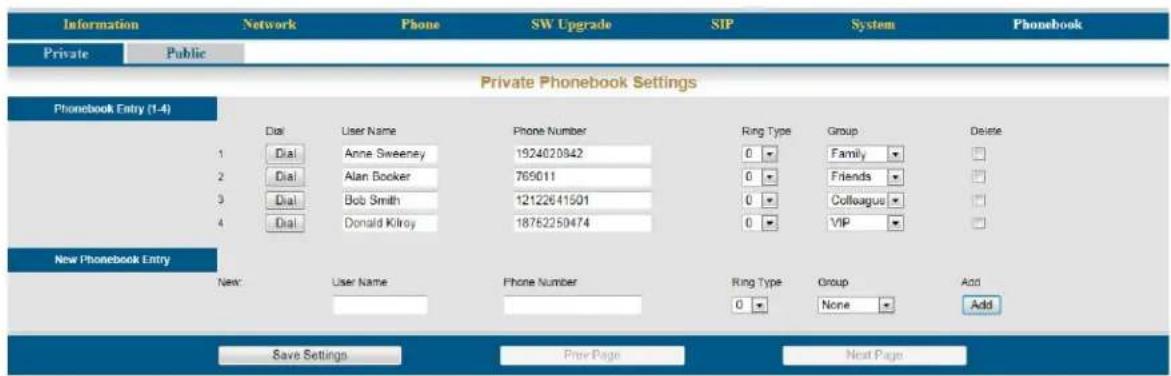
text_image
Information Network Phone SW Upgrade SIP System Phonebook Private Public Private Phonebook Settings Phonebook Entry (1-4) Dial User Name Phone Number Ring Type Group Delete 1 Dial Anne Sweeney 1924020942 0 Family □ 2 Dial Alan Booker 769011 0 Friends □ 3 Dial Bob Smith 12122641501 0 Colloagus □ 4 Dial Donald Kilroy 18762250474 0 VIP □ New Phonebook Entry New: User Name Phone Number Ring Type Group Add Save Settings Free Page Next PageEnter the four parameters and then press the "Add" button, to add new entries.
- User Name: - Enter the user name that will be associated with this entry.
- Phone Number: - Enter the phone number (up to 64) digits.
- Ring Type: - There are eleven different ring tones that can be used to differentiate the entered telephone number when it calls into the system.
- Select the Group that will be associated with the entered telephone number. Select between Family, Friends, Colleague, VIP or None.
It is a good idea to create a back up of the configuration file once all of the numbers are entered. The user can create a back up by clicking on the "SW Upgrade" tab and then click on the "Backup" button. Be sure to locate the file where it is easy to locate should it be needed.
Click on the "Backup Button" and save it in a location that is easy to locate when needed.

text_image
Software Upgrade HTTP Upgrade Software File: Browse... Configuration File: Browse... Private Phonebook File: Browse... Public Phonebook File: Browse... Update Update Update Update Backup Backup Create a backupPublic
The Public phonebook gets linked to a CSV file in a centralled location, allowing an administrator to update all phones connected to the system with a single file. There are several ways to create a CSV file. One way is to use the backup created from the personal phonebook. Another way to create the file is using Windows Notepad. Once created save it with a name such as "Publicphonebook.csv, and place it in a location that is easily found.
The format of this file is very important:
Name, Number, Ring, Group,
Anne Sweeney,1924020842,0,family,
Alan Booker,769011,0,Friends,
Bob Smith, 12122641501, 0, Colleague,
Donald Kilroy, 18752250474, 0, VIP,
One the file is ready to be uploaded, click on the "SW Upgrade" tab.

text_image
Software Upgrade HTTP Upgrade Software File: Browse... Configuration File: Browse... Private Phonebook File: Browse... Public Phonebook File: Browse... Update Update Update Update Backup Backup- Locate the "Public Phonebook File:" and click on the Browse... button
- Locate the saved file
- Click on the Update button
- Click on "OK" to complete the upload or "Cancel" to stop the upload.
- Click on the Phonebook tab, and then the Public Page tab. If the file format is correct, the informaiotn will be visible. If the numbers are not visible recheck the file format.
Notes:
Phone Lock/Unlock
Description:
The phone Lock/Unlock feature allows the user to lock their extension to prevent someone from making unauthorized calls from their extension. The phone lock/unlock feature does not block intercom or emergency calls, it only blocks telephone line (PSTN or SIP Trunk) calls.
Operation:
- To lock the phone dial *97 + extension (mailbox) password
- To unlock the phone dial **97 + extension (mailbox) password
Notes:
- Locked extensions can only make intercom or emergency calls
Plug and Play
Description:
When connecting an X2020 to the X-50 system over the LAN it will automatically authenticate and be assigned an extension number and activate the mailbox. An extension connecting over the WAN port will also automatically authenticate, be assigned an extension number, and activate the mailbox but requires some basic programming.
Operation:
Connect the X2020 telephone to the LAN port, no other programming is required. When Connecting over the WAN port, there are four parameters that need to be programmed; the SIP Proxy Server, Outbound Proxy Server, Registrar Server, Registrar Outbound Server. This programming can be done using the telephone menu or using a standard Internet Web Browser.
Notes:
- Although WAN extensions will automatically receive an extension number it is a good idea to enter their extensions manually to make them more perminate. It has been found that after a power outage, for example, the extension numbers may change.
Reminder Tone
Description:
When the extension goes off hook, speaker or handset, stutter dial tone will be heard when DND, MWI or Call Forward is enabled.
Operation:
This is an automatic feature
Notes:
Service Mode
Description:
The Operator has the ability to change the mode of the system from day mode to night mode or timed mode. When the system is set to day mode, the Auto Attendant will only play the day greeting and extensions will use the day Class of Service for dialing privileges. When the system is in night mode, the Auto Attendant will only play the night greeting and extensions will use the night Class of Service for dialing privileges. When the system is in timed mode the system will automatically switch between day, lunch and night modes using the service mode settings in the X-50 system.
Operation:
Only the attendant has the ability to swap between the service modes:
• Dial: *790 - displays the current mode
- Dial: *791 - changes the system into Day mode
- Dial: *792 - changes the system into Night mode
- Dial: *793 - changes the system into time mode to automatically change between modes.
Notes:
- This feature only works with the attendant extension
Telephone Line Flash
Description:
The flash command is used to activate a telephone line feature, such as call waiting or three way calling.
Operation:
While on a telephone line call, X2020 telephone users may press the software button under the word "Flash".
Notes:
- When using an analog (Single Line) telephone without a "Flash" key may cause erratic operation.
- Use *790 when programming a button to toggle between day and night modes.
Transfer
Description:
Calls can be transferred from an extension to another destination, such as another extension, voice mail, or an outside number. In addition, transfers can be blind, without announcing the call, supervised, listening for call supervision, or screened where the transferring extension can announce the call.
Operation:
- While on a telephone line call press the transfer button
- Press the preprogrammed DSS button or dial the desired destination
- Hang up to release the call, or remain on the line to announce the call
Notes:
- If the receiving extension is forwarded, the transferred call will follow the forwarding
- If the receiving extension is not forwarded, and goes unanswered, it will recall at the extension that transferred the call
Volume Control
Description:
The X2020 system is equipped to adjust the volume levels of the following settings:
• Ringing (extension and telephone line)
- Handset
- speaker
- Headset
Operation:
Press the volume up to increase or down to decrease the volume of the currently used feature. For example, while the telephone is ringing use the volume button to increase or decrease the ringing volume.
Notes:
Web Management
Description:
The X2020 can be programmed using the LCD menu or using a standard Internet Web Browser, such as Windows Internet Explorer.
Operation:
Enter the IP Address in the browser address bar to access the Web interface page for programming.
Notes:
Telephone Feature Description Table
Notes:
5 / n s t a l l a t i o n
Installation Planning
This chapter will show how to prepare and install the X-50 system and basic networking setup and protocol.
Basics
- Never perform any wiring in a wet location, while standing in water or during a lightning storm.
- The H-50 should be installed in a well lit location with proper ventilation, having an optimum temperature range from 40° to 95° F and a relative humidity range of 20 to 80 percent.
- The X-50 should not be installed where it will be exposed to direct sunlight or heat.
- Do not install the X-50 close to or in a strong magnetic field, such as those generated by heavy motors, televisions, copy machines or some kitchen appliances. Ideally, the X-50 should be installed in an electrically noise-free environment to avoid interference.
- Be careful when connecting any type of antenna or power through a cable that will be connected directly or indirectly to the X-50.
Note:
The manufacturer Warranty does not cover damage caused by abuse, electrical or telephone line power surges or lightning damage.
Where to begin
The X-50 can be mounted in one of three different ways, virticall, horizontally, or wall mounted. See "Wall Mount Template" for wall mounting in structions
Vertically

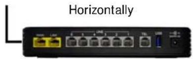
text_image
HorizontallyFor best results;
- If using PSTN telephone lines the X-50 should be installed near where they enter the building, which is called the "RJ21X".
- The X-50 should be installed in a server room or anywhere that is a computer might be placed. It should be placed on a clean hard service or mounted on a wall.
- The X-50 should be connected to all devices using Category 5, Category 5E or Category 6 cables.
- The X-50 should be in a location that is easily accessible by anyone who may need to perform maintenance on the unit.
- The "TEL" port (analog telephone port) on the X-50 may be connected directly to a standard corded, cordless telephone or FAX machine.
- The X-50 should be placed on a line condition Uninterrupted Power Supply (UPS) system which will provide line conditioning and battery back up during a power outage. To minimize the number of UPS systems needed, power all telephone endpoints using Power of the Ethernet (PoE).
Logical
- Will this system be a standalone system or part of a voice network?
This will help determine the numbering plan and the LAN/WAN requirements. If the X-50 is going to be a standalone system, the default numbering plan should be fine. However, if the system is going to be connected to a voice network, the numbering plan may need to be modified to allow direct dialing to specific locations. See "Numbering Plan" on page 91. In addition, a standalone system may not need to be connected to the Internet, so there is no need to set up the "WAN" port, and the system's location is a lot more flexible.
- Will this system be the "Master" system in a Voice Network?
If this system is part of a voice network, will it be the master system? If so, it will require a "Static IP Address". If not, it can use a DHCP Address, because it will be programmed to synchronize with the master system.
- Will this system have any remote workers?
A remote worker is someone who uses the telephone system's resources but does not reside in the same building or physical area. Connecting remote workers requires a static Class A or B IP Address and the ISP's DSL/Cable modem should be programmed as a bridge or concurrent bridge.
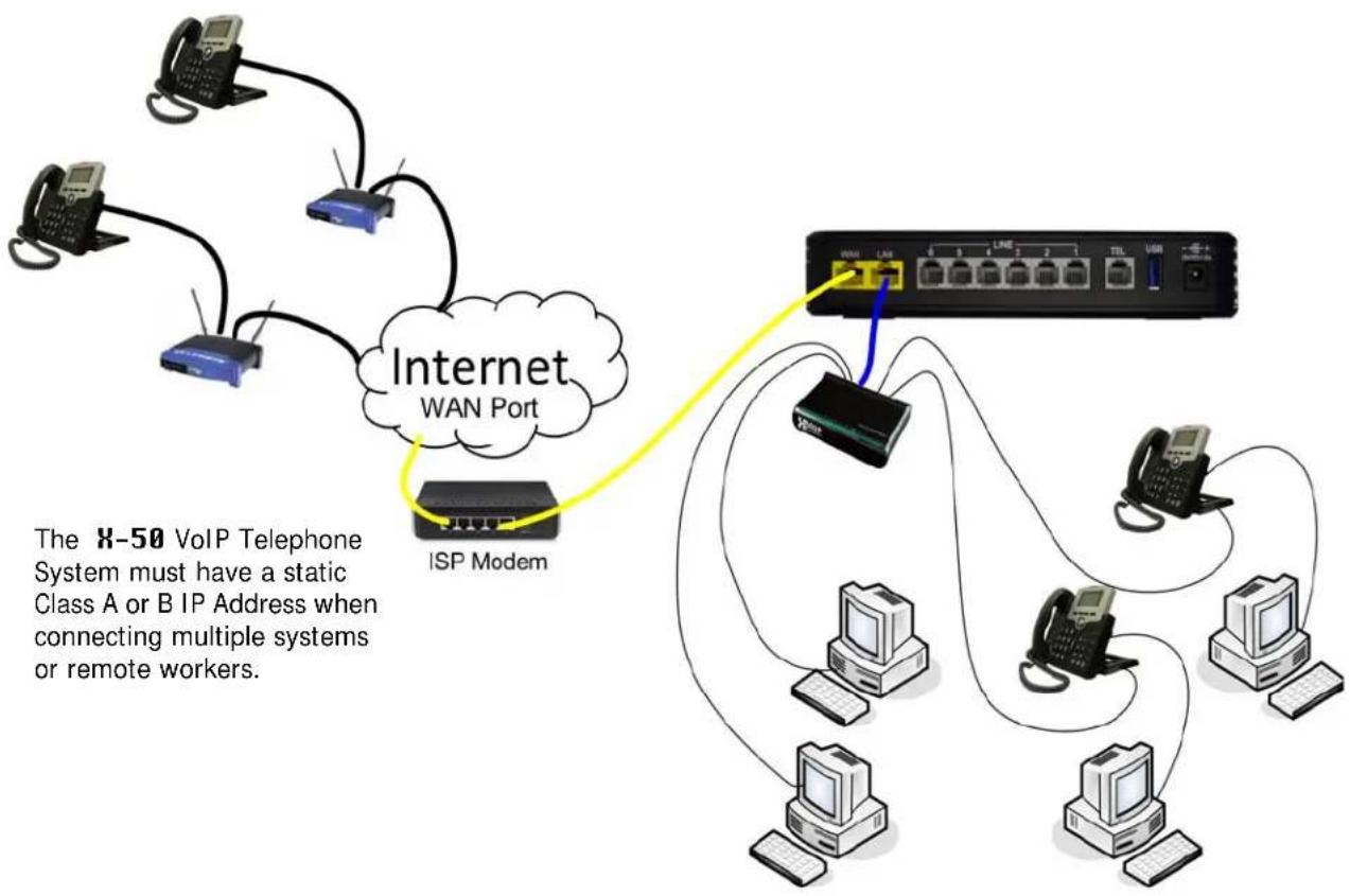
flowchart
graph TD
    A["Windows"] --> B["Internet WAN Port"]
    C["USB"] --> B
    D["PC"] --> B
    E["Windows"] --> B
    F["USB"] --> B
    G["PC"] --> H["ISP Modem"]
    I["Windows"] --> H
    J["USB"] --> H
    K["PC"] --> H
    L["Windows"] --> H
    M["USB"] --> H
    N["PC"] --> H
    O["Windows"] --> H
    P["USB"] --> H
    Q["PC"] --> H
    R["Windows"] --> H
    S["USB"] --> H
    T["PC"] --> H
    U["Windows"] --> H
    V["USB"] --> H
    W["PC"] --> H
    X["Windows"] --> H
    Y["USB"] --> H
    Z["PC"] --> H
    AA["Windows"] --> H
    AB["USB"] --> H
    AC["PC"] --> H
    AD["Windows"] --> H
    AE["USB"] --> H
    AF["PC"] --> H
    AG["Windows"] --> H
    AH["USB"] --> H
    AI["PC"] --> H
    AJ["Windows"] --> H
    AK["USB"] --> H
    AL["PC"] --> H
    AM["Windows"] --> H
    AN["USB"] --> H
    AO["PC"] --> H
    AP["Windows"] --> H
    AQ["USB"] --> H
    AR["PC"] --> H
    AS["Windows"] --> H
    AT["USB"] --> H
    AU["PC"] --> H
    AV["Windows"] --> H
    AW["USB"] --> H
    AX["PC"] --> H
    AY["Windows"] --> X["Internet WAN Port"]
    AZ["ISP Modem"] --> X
    BA["X-50 VoIP Telephone System must have a static Class A or B IP Address when connecting multiple systems or remote workers."]
- Will the system be connected to PSTN Lines?
This may determine where the system will be located. If PSTN lines are being used it is a good idea to locate the X-50 VoIP Telephone System close to where they enter the building.
- Will the system join an existing network or will it be on its own network?
If joining an existing network, Connect the WAN port of the X-50 to the current network. It will then act as both a WAN and a LAN. Also, if there is more than one wireless device make sure that they are not all using the same channel.
Joining an existing Local Area Network
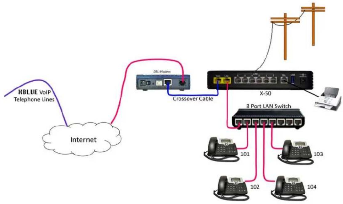
flowchart
graph TD
    A["Internet"] -->|XBLUE VoIP Telephone Lines| B["DSL Moders"]
    B -->|Crossover Cable| C["X-50"]
    C --> D["8 Port LAN Switch"]
    D --> E["101"]
    D --> F["102"]
    D --> G["103"]
    D --> H["104"]
    C --> I["Computer"]
    style A fill:#f9f,stroke:#333
    style B fill:#ccf,stroke:#333
    style C fill:#cfc,stroke:#333
    style D fill:#fcc,stroke:#333
    style E fill:#cff,stroke:#333
    style F fill:#ffc,stroke:#333
    style G fill:#cfc,stroke:#333
    style H fill:#fcc,stroke:#333
If the system is going to be a standalone system, with isolated cables for VoIP, there is no need to connect it to the Internet, except for remote programming.
A standalone Voice network.
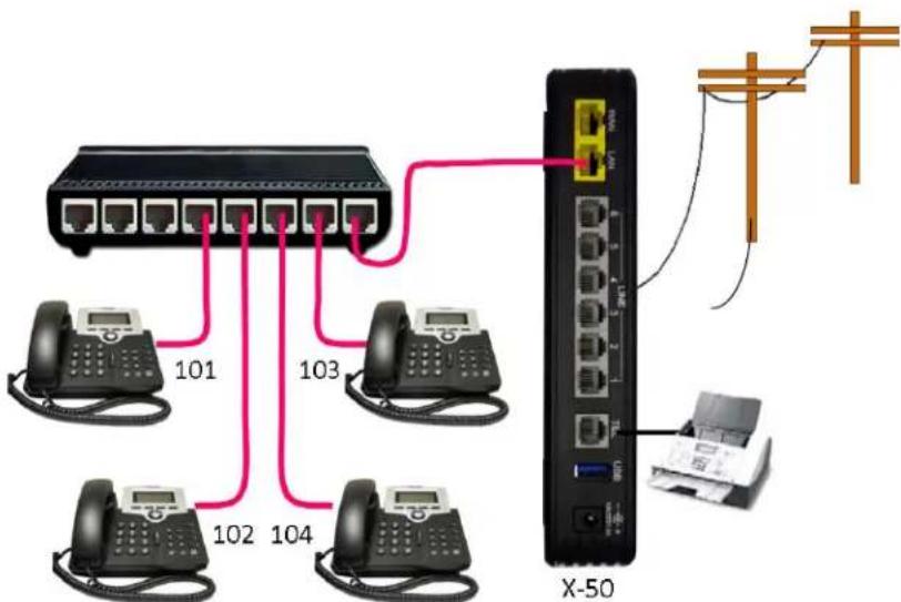
text_image
101 103 102 104 X-50Physical
- Locate where the PSTN telephone and DSL/Cable lines enter the building.
The X-50 has six FXO ports, which supports standar Public Switched Telephone Network (PSTN) telephone lines. In addition, it has both a LAN and a WAN port, which may be connected to an existing network as well as a Wireless LAN. Therefore, the X-50 will need to be located in an area that will allow it to be connected to both the PSTN telephone lines and any existing network switch, router or gateway.
When using PSTN lines, it is a good idea to install the X-50 close to where the telephone lines enter the office or building. However, if only "SIP Trunks" are going to be used, which is not recommended because of power outages and emergencies, the system can be located near where the Internet Service Provider's (ISP) DSL/Cable modem enters the building.
- Verify that all cables, between data devices, are Category 5, 5E or 6.
All devices connected to the X-50 must use a Category 5, 5E or 6 high speed Ethernet cable. This will ensure the best data transfer rates. Failure to use the correct cable will cause spotty results in voice communication.
- Cables between the FXS Port, labeled "TEL" (Analog Telepone Port) or PSTN telephone lines can be Category 3, 5, 5E or 6. It is acceptable to use Category 3 cabling when connecting the FXO (Telephone Lines) and the FXS (Single Line Telephone).
Installing the X-50 VoIP Telephone System
- Remove all of the components from the box.
- Wall Mount - locate the supplied wall template and secure it to the wall. Drill starter holes and place the supplied anchors into the holes. Position the supplied screws into the anchors and secure them. It will be necessary to back the screws out about 1/4 of an inch to securely hold the system on the wall.
- Table or shelf Mount - There are two ways to mount the system on a table or shelf, vertical and horizontal, neither has an advantage over the other.
Vertical Installation - the system comes with a special weighted base stand designed to secure the X-50 VoIP Telephone System in a vertical position.
Horizontal Installation - the system also comes equipped with "Rubber" feet at the bottom of the unit so that it can be placed on a table or shelf with a low profile. The Antenna, for the Wireless LAN, will bend at 90 degrees so that it can be tilted upward.
The X-50 is designed to operate either vertically or horizontally.
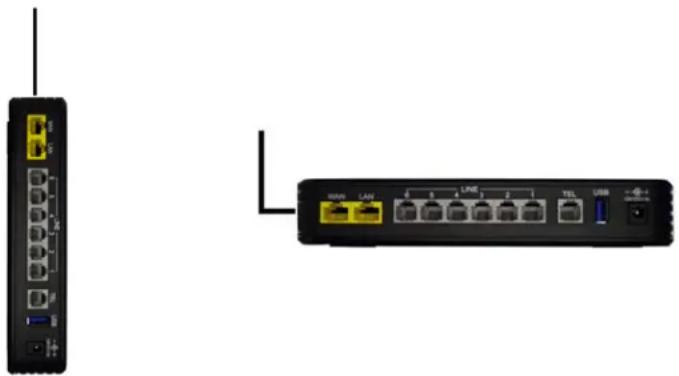
natural_image
Two network devices: a black wireless router with ports and a black wireless router with ports and cables, shown without any text or labels.Before Programming the X-50
Because the X-50 is a complete Gateway and Router, including a DHCP server it is a good idea to do some basic programming before connecting it to an existing network. Connect a PC to the X-50 LAN Port, using the supplied Patch Cable and then power up the X-50 system. If the user's PC is set to DHCP, it will connect to the X-50 and the two devices will become a network. The Gateway's default IP Address is 192.168.10.1.
6 Programming Wizard
Getting Started
The X-50 is a fully functioning Voice over Internet Protocol (VoIP) Gateway and router, which is programmed using a standard Internet browser such as Microsoft's Internet Explorer®. Any computer with a Network Interface Card (NIC), connected to a TCP/IP network, can be used to program the X-50 VoIP Telephone System.
Setup Wizard
Once the administrator logs in and authenticates the first time, the programming wizard will walk the administrator through the programming process. The next time the administrator logs into the X-50, after the programming wizard is completed, the administrator will be sent to the main programming landing page which shows the current status of the X-50 VoIP Telephone System.
There are two ways to begin programming the X-50 system; manually or restore from a backup.
If restoring a backup, Click the next button and then locate the backup file and click on the Update Settings button. The update will take about 2 minutes.
The system will reboot after uploading the configuraiton file.
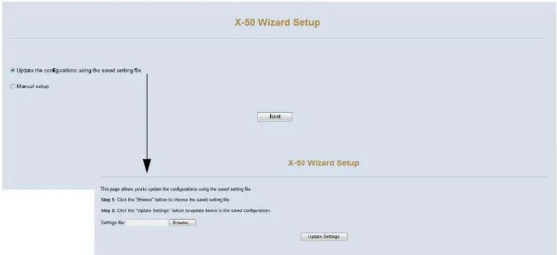
text_image
X-50 Wizard Setup Update the configurations using the saved setting file. Manual setup Next X-50 Wizard Setup This page allows you to update the configurations using the saved setting file. Step 1: Click the "Browse" button to choose the saved setting file. Step 2: Click the "Update Settings" button to update device to the saved configurations. Settings file: Browse... Update SettingsThe Setup Wizard guides the administrator through the required setup parameters to make the X-50 operational. The Setup Wizard must be completed at least once, before gaining access to the "Advanced Setup" programming area. If any of the parameters are unknown, just press "Next" and continue. All of these parameters can be adjusted later using the "Advanced Setup" area.

text_image
X-50 Wizard Setup WAN Settings LAN Settings Wireless Basic Internet Time Numbering Plan IP Trunk Trunk DID Call Routing TableSetup Wizard Tabs
- WAN Settings (See "WAN Port Settings" on page 83.)
• LAN Settings (See "LAN Port Settings" on page 87.) - Wireless Basic (See "Wireless Basics" on page 89.)
- Internet Time (See "Internet Time" on page 90.)
• Numbering Plan (See "Numbering Plan" on page 91.) - IP Trunks (if needed) (See "SIP Trunks" on page 94.)
• DID Trunks (Requires IP TRunk) (See "SIP Trunks" on page 94.) - Call Routing Table (See "Call Routing Table" on page 97.)

Before beginning the installation process it is a good idea to gather as much networking information as possible. This includes IP Addresses for the LAN, WAN, Default Gateway, Subnet, etc. It is also a good idea to make a note of all MAC Addresses for all wireless devices as well as system or voice network numbing plan, SIP trunk information and how dialed numbers will be routed.
WAN Port Settings
The WAN Settings Tab is automatically selected and the default page in the Setup Wizard. Unlike a LAN port, the WAN port can be used to redirect class A or B IP Addresses from an external location, such as the Internet, to a specific internal Port. This process is called Network Address Translation or NAT.
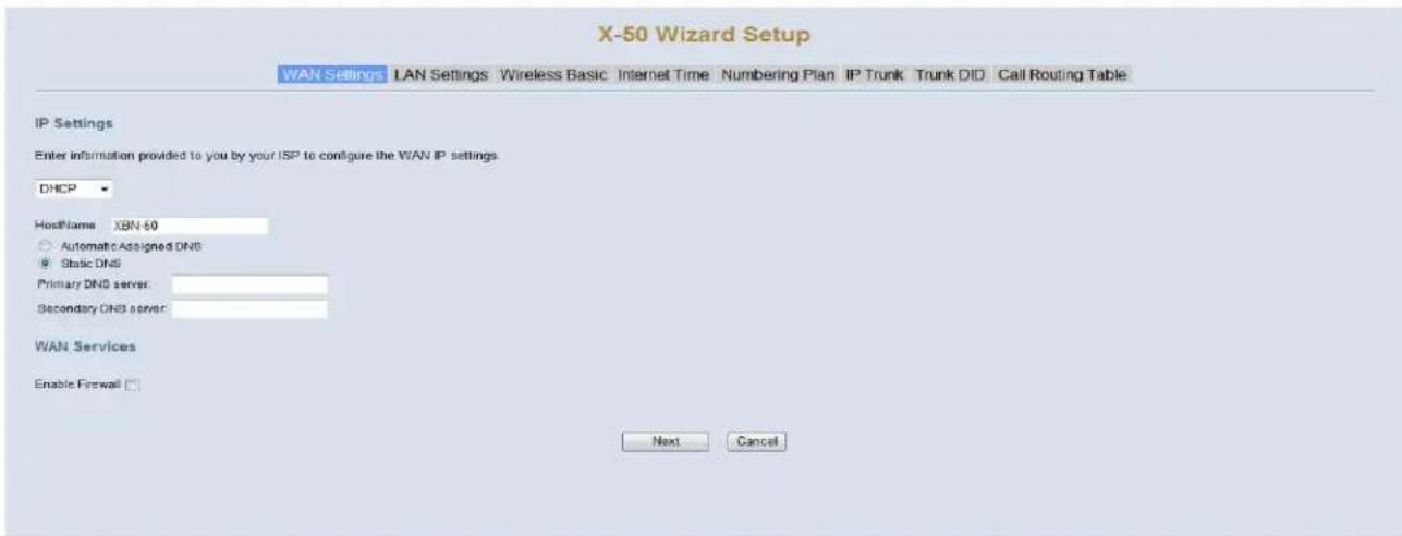
text_image
X-50 Wizard Setup WAN Settings LAN Settings Wireless Basic Internet Time Numbering Plan IP Trunk Trunk DID Call Routing Table IP Settings Enter information provided to you by your ISP to configure the WAN IP settings DHCP HostName XBN-60 Automatic Assigned DNS Static DNS Primary DNS server: Secondary DNS server: WAN Services Enable Firewall Next CancelIP Settings (Default)
- At default, the "WAN Port Settings" are set to Automatic Configuration - DHCP. Dynamic Host Configuration Protocol (DHCP) allows the WAN port of the system to automatically receive an IP and Subnet Mask Addresses from the Internet Service Provider (ISP).
- The system can use either dynamic (automatically assigned) or Static DNS settings. Unless required by the ISP it is probably easier to leave this set to automatic.
WAN Services
- Enable Firewall - Although nothing is 100% safe against malicious network attacks, keeping the firewall enabled, should minimize the effectiveness of these attacks.
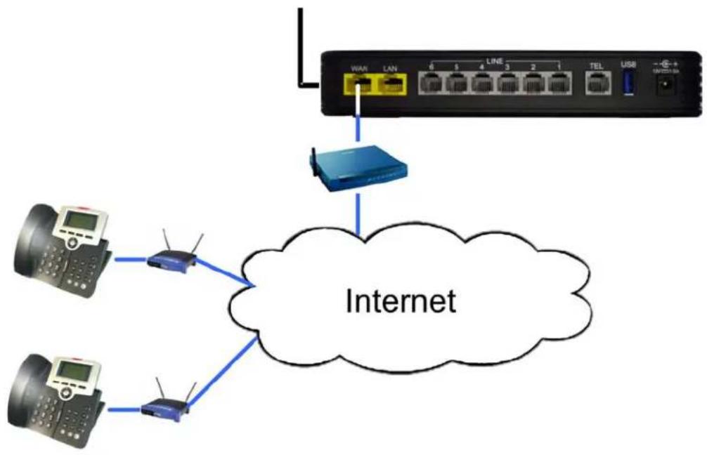
flowchart
graph TD
    A["Client 1"] --> B["Router"]
    C["Client 2"] --> B
    D["Client 3"] --> B
    E["Client 4"] --> B
    F["Client 5"] --> B
    G["Client 6"] --> B
    H["Client 7"] --> B
    I["Client 8"] --> B
    J["Client 9"] --> B
    K["Client 10"] --> B
    L["Client 11"] --> B
    M["Client 12"] --> B
    N["Client 13"] --> B
    O["Client 14"] --> B
    P["Client 15"] --> B
    Q["Client 16"] --> B
    R["Client 17"] --> B
    S["Client 18"] --> B
    T["Client 19"] --> B
    U["Client 20"] --> B
    V["Client 21"] --> B
    W["Client 22"] --> B
    X["Client 23"] --> B
    Y["Client 24"] --> B
    Z["Client 25"] --> B
    AA["Client 26"] --> B
    AB["Client 27"] --> B
    AC["Client 28"] --> B
    AD["Client 29"] --> B
    AE["Client 30"] --> B
    AF["Client 31"] --> B
    AG["Client 32"] --> B
    AH["Client 33"] --> B
    AI["Client 34"] --> B
    AJ["Client 35"] --> B
    AK["Client 36"] --> B
    AL["Client 37"] --> B
    AM["Client 38"] --> B
    AN["Client 39"] --> B
    AO["Client 40"] --> B
    AP["Client 41"] --> B
    AQ["Client 42"] --> B
    AR["Client 43"] --> B
    AS["Client 44"] --> B
    AT["Client 45"] --> B
    AU["Client 46"] --> B
    AV["Client 47"] --> B
    AW["Client 48"] --> B
    AX["Client 49"] --> B
    AY["Wi-Fi LAN 6-4 Line 3-1 TEL USB"]
    AZ["Internet"]
IP Settings (Static IP Address)
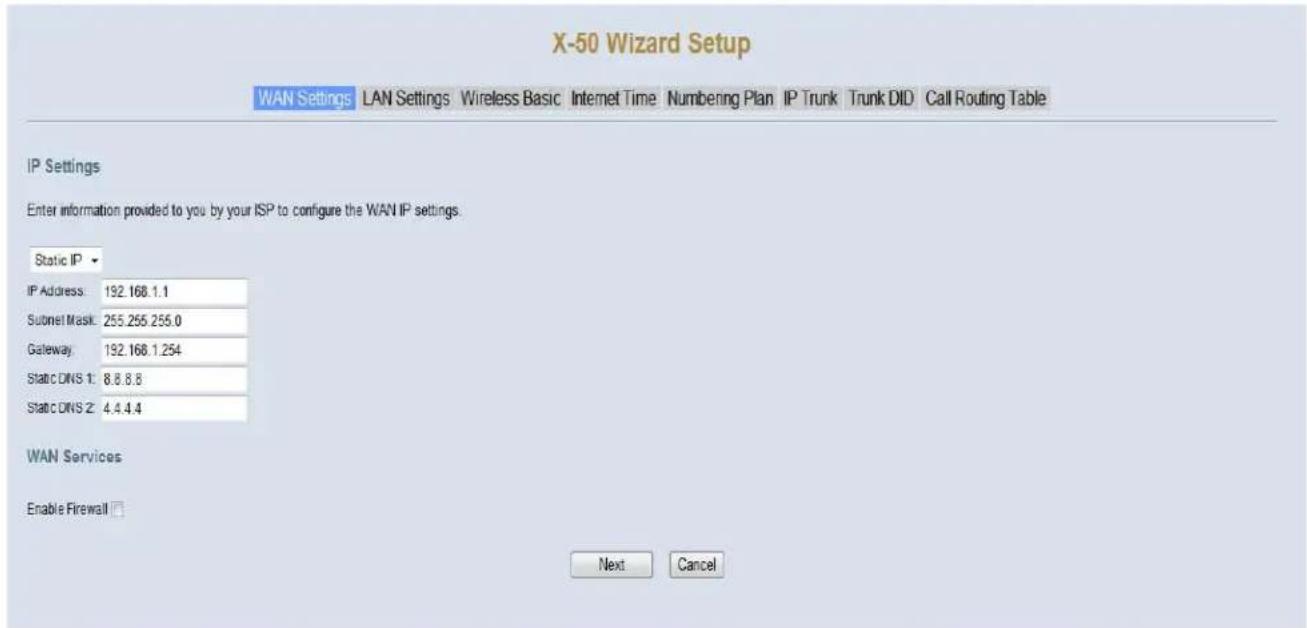
text_image
X-50 Wizard Setup WAN Settings LAN Settings Wireless Basic Internet Time Numbering Plan IP Trunk Trunk DID Call Routing Table IP Settings Enter information provided to you by your ISP to configure the WAN IP settings. Static IP IP Address: 192.168.1.1 Subnet Mask: 255.255.255.0 Gateway: 192.168.1.254 Static DNS 1: 8.8.8.8 Static DNS 2: 4.4.4.4 WAN Services Enable Firewall Next CancelDepending on the installation it may be possible to configure the WAN port to use a “Static IP Address”, which can be used by some ISP’s but generally is used when the system is not part of a voice network or supporting remote workers. For example, when using e-mail delivery or NAT for remote to programming. This parameter makes it easier for network administrators to enter a specific IP Address, which they often reserve for printers, servers, routers, and gateways.
- Internet IP Address - Enter the IP address that will be used to identify the X-50 system.
- Subnet Mask - when using "Static IP Address" the Subnet Mask will have to be entered by the administrator. If there is a single Subnet, the entry will be 255.255.255.0.
- Gateway - The Default Gateway refers to the Gateway device that connects the Intranet (LAN) to the Internet. Basically, it is the window to the Internet.
- Static DNS 1 & 2 - The Domain Name System (DNS) the Internet's phone book, and is used to translate IP Addresses to something that is easy to remember such as "xbluenetworks.com". Some Internet Service Providers (ISP) require Static DNS when using static IP Addresses.
WAN Services
- Enable Firewall - Although nothing is 100% safe against malicious network attacks, keeping the firewall enabled should minimize the effectiveness of these attacks.
Point-to-Point Protocol over Ethernet (PPPOE)
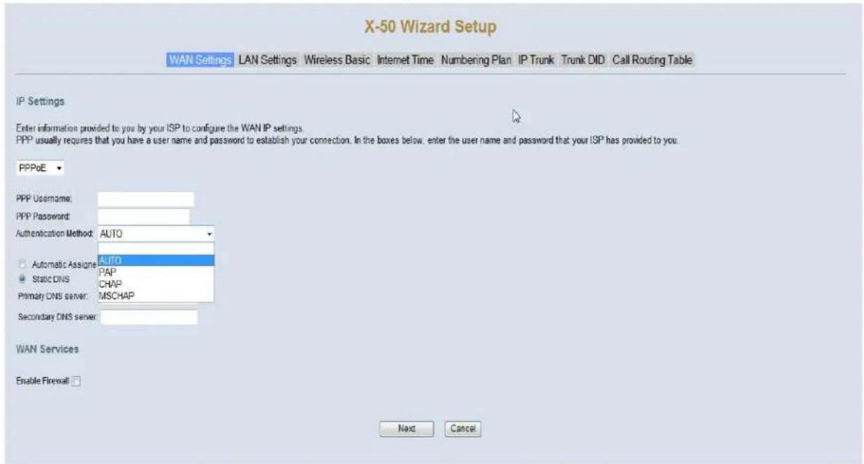
text_image
X-50 Wizard Setup WAN Settings LAN Settings Wireless Basic Internet Time Numbering Plan IP Trunk Trunk DID Call Routing Table IP Settings Enter information provided to you by your ISP to configure the WAN IP settings. PPP usually requires that you have a user name and password to establish your connection. In the boxes below, enter the user name and password that your ISP has provided to you. PPPoE PPP Username: PPP Password: Authentication Method: AUTO Automatic Assigne AUTO Static DNS PAP Primary DNS server: MSCHAP Secondary DNS server: WAN Services Enable Firewall Next CancelThe WAN Port of the X-50 can also be set to PPPoE. In this case, the Internet Service Provider (ISP) will supply the administrator with a User Name and Password (most likely it will be case sensitive), which is required when connecting the WAN port to the Internet. The ISP's modem/gateway must be set as a bridge, allowing the X-50 system to authenticate directly with the ISP.
• Automatic (Auto) - This will automatically negotiate the correct authentication protocol.
- Password Authentication Protocol (PAP) - This will send the authentication un-encrypted.
- Challenge Handshake Authentication (CHAP) - This is more secure than the aforementioned PAP, and sends the authentication encrypted.
- Microsoft's version of CHAP that allows mutual authentication between peers, by piggybacking challenge and response packets on a successful packet.
- Static DNS 1 & 2 - The Domain Name System (DNS) the Internet's phone book, and is used to translate IP Addresses to something that is easy to remember such as "xbluenetworks.com". Some Internet Service Providers (ISP) require Static DNS when using static IP Addresses.
WAN Services
- Enable Firewall - Although nothing is 100% safe against malicious network attacks, keeping the firewall enabled, should minimize the effectiveness of these attacks.
LAN Port Settings
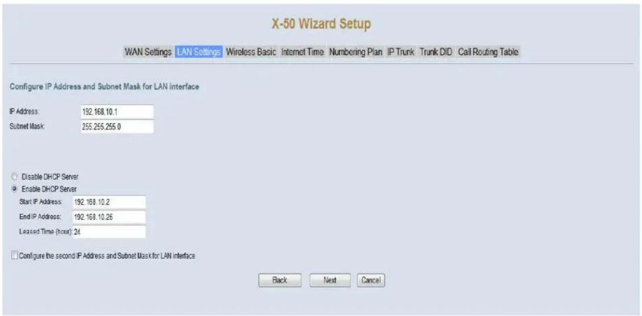
text_image
X-50 Wizard Setup WAN Settings LAN Settings Wireless Basic Internet Time Numbering Plan IP Trunk Trunk DID Call Routing Table Configure IP Address and Subnet Mask for LAN interface IP Address: 192.168.10.1 Subnet Mask: 255.255.255.0 Disable DHCP Server Enable DHCP Server Start IP Address: 192.168.10.2 End IP Address: 192.168.10.25 Leased Time (hour): 24 Configure the second IP Address and Subnet Mask for LAN interface Back Next CancelOnce the WAN port settings are complete, press next to get to the Local Area Network (LAN) Port Settings page. At default the LAN IP Address is set to 192.168.10.1 and Dynamic Host Configuration Protocol (DHCP) server is enabled.

text_image
ClueThe X-50 system is a gateway, which joins two or more different types of networks together, such as WAN, LAN and PSTN. If the X-50 system is connected to the ISP through a bridge to allow for connecting to external devices. The LAN Address will be set to 192.168.10.1 and it is set to be the network's DHCP Server.
However, if the X-50 is only using email delivery and remote
programming then the WAN port can be set to join as a node or client on the existing Local Area Network.
When connecting the WAN port of the X-50 to an existing LAN, the LAN port of the X-50 must be given a different IP address such as (192.168.100.1). The LAN of the X-50 is then considered "Down Stream" from the existing LAN.
When establishing any network numbering plan, do not use the IP address x.x.x.254 because this address is reserved for the system's DSP and will cause erratic operation.
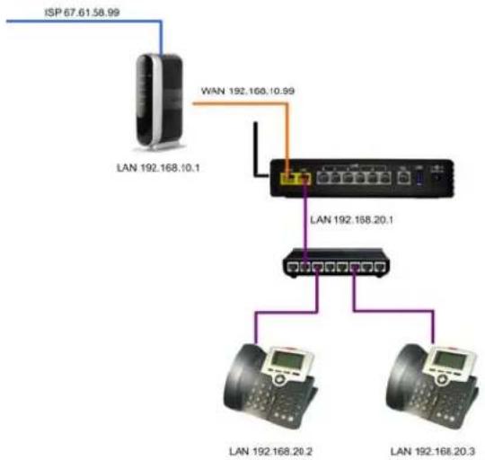
flowchart
graph TD
    A["ISP 67.61.58.99"] --> B["LAN 192.168.10.1"]
    C["WAN 192.168.10.99"] --> D["LAN 192.168.20.1"]
    B --> E["LAN 192.168.20.2"]
    D --> F["LAN 192.168.20.3"]
Configure IP Address and Subnet Mask for LAN Interface
- LAN IP Address - at default the LAN IP Address is set to 192.168.10.1, but can be customized to accommodate any valid IP Address. In addition, the LAN IP Address is considered the default gateway for any of the SIP telephone endpoints connected within the LAN. When establishing any network numbering plan, do not use the IP address x.x.x.254 because this address is reservered for the system's DSP and will cause erratic operation.
- Subnet Mask - when using the "Static IP Address" setting, the Subnet Mask will have to be Manually entered. If there is a single Subnet, the entry will be 255.255.255.0.
- Universal Plug and Play (UPnP) - When enabled, the X-50 will recognize any device that is connected to the LAN port and begins broadcast UPnP protocol.
- Dynamic Host Configuration Protocol (DHCP) Server - When enabled the X-50 can be used to automatically assign client devices an IP Address. In addition, the administrator can grant a specific range of valid IP Addresses. At default the DHCP is enabled and will allow from 192.168.10.2 to 192.168.10.25 but can be expanded to 192.168.10.253. When disabled, every device connected to the network will have to be manually configured with an IP Address, which is good for security but creates a lot of extra work for the administrator. When establishing any network numbering plan, do not use the IP address x.x.x.254 because this address is reserved for the system's DSP and will cause erratic operation.
- Leased Time - The amount of time that each dynamically assigned IP Address will be assigned to any one device before it is renewed. If the device is still connected and active the device will probably continue with the same IP Address. However, if the device has been removed and inactive for more than the lease time, it may be assigned a different IP Address the next time it is connected.
Wireless Basics
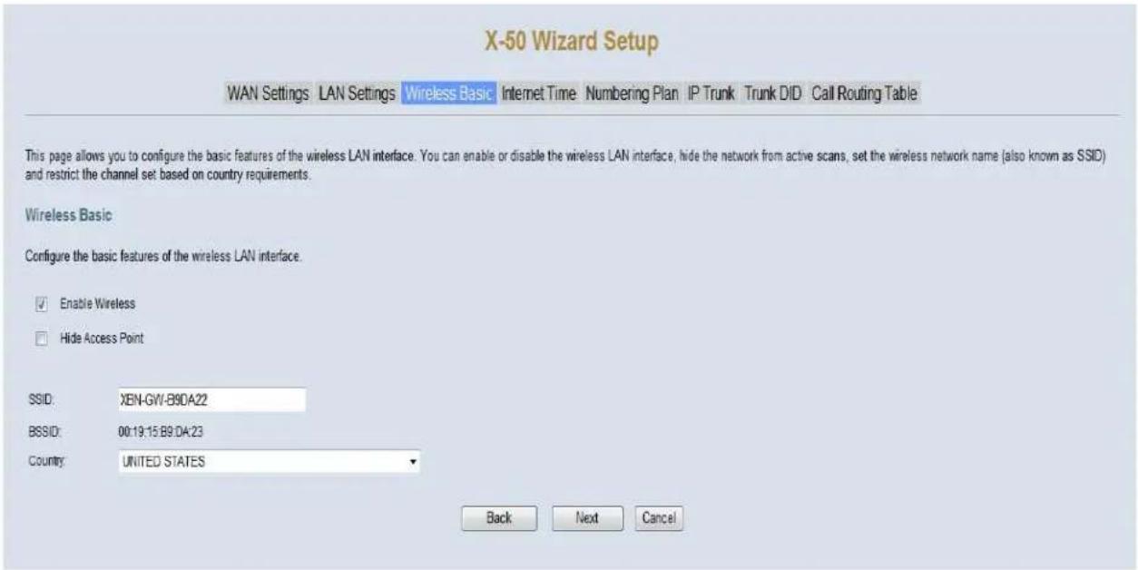
text_image
X-50 Wizard Setup WAN Settings LAN Settings Wireless Basic Internet Time Numbering Plan IP Trunk Trunk DID Call Routing Table This page allows you to configure the basic features of the wireless LAN interface. You can enable or disable the wireless LAN interface, hide the network from active scans, set the wireless network name (also known as SSID) and restrict the channel set based on country requirements. Wireless Basic Configure the basic features of the wireless LAN interface. Enable Wireless Hide Access Point SSID: XEN-GW-B9DA22 BSSID: 00:19:15 B9:04:23 Country: UNITED STATES Back Next CancelThe X-50 is equipped with a wireless router, which allows wireless devices to connect using 802.11b, 802.11g and 802.11n protocol speeds.
- Enable Wireless - The wireless router is enabled at default, and can be disabled by un-checking this parameter.
- Hide Access Point - Check this parameter to "hide" the X-50 wireless signal. This stops the SSID from being broadcast, making it harder for unauthorized endpoints to access the Wireless Access Point (WAP). When SSID is disabled, the user must enter the specific IP Address of the X-50 to connected wirelessly.
- SSID - Service Set Identifier - This is the name that will be broadcast to make it easier for authorized endpoints to connect to the X-50 wirelessly.
- BSSID - Basic Service Set Identifier - uniquely identifies each Basic Service Set (BSS), which is the building block for all 802.11(x) devices. The BSSID is a locally administered MAC Address of the Wireless Access Point (WAP).
- The Country parameter determines the frequencies and restricts based on country requirements.
Internet Time
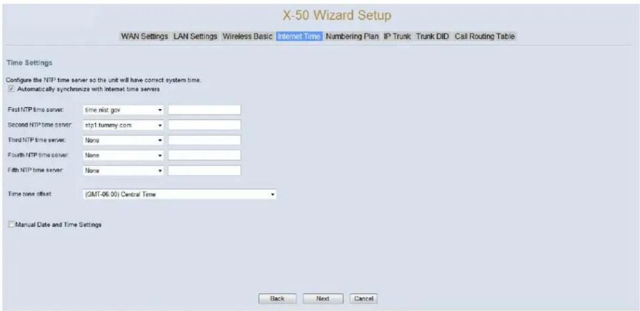
text_image
X-50 Wizard Setup WAN Settings LAN Settings Wireless Basic Internet Time Numbering Plan IP Trunk Trunk DID Call Routing Table Time Settings Configure the NTP time server so the unit will have correct system time: ✓ Automatically synchronize with Internet time servers First NTP time server: time.nist.gov Second NTP time server: ntp1.tummy.com Third NTP time server: None Fourth NTP time server: None Fifth NTP time server: None Time zone offset (GMT-06.00) Central Time Manual Date and Time Settings Back Next CancelThe X-50 can be set to synchronize its date and time with specific sites found on the internet. This is referred to as "Network Time Protocol (NTP)".
- The H-50 allows for up to five different time server locations to be used to synchronize the time. Therefore, if one or more servers fail, the time will not be lost. It is a good idea to select at least one primary and one secondary time server, however, only the primary is required. Use the drop down menu, to select the desired timer server.
- Time Zone Offset - This is the amount of time added or deducted from Greenwich Mean Time (GMT)
If the system is not connected to the Internet, click on "Manual Date and Time Settings" to enter the time manually. Do not reset the system after the date and time is set manually, it may cause the system time to adjust erratically.
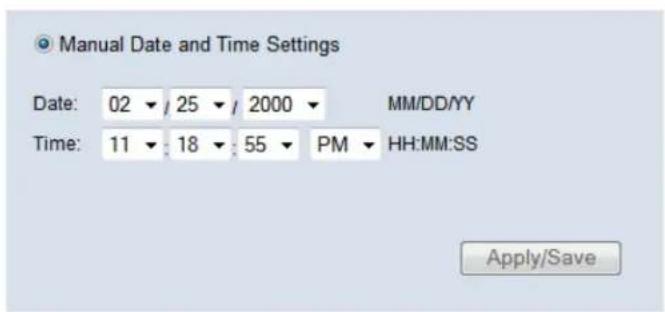
text_image
Manual Date and Time Settings Date: 02 / 25 / 2000 MM/DD/YY Time: 11 / 18 : 55 PM HH:MM:SS Apply/SaveNumbering Plan
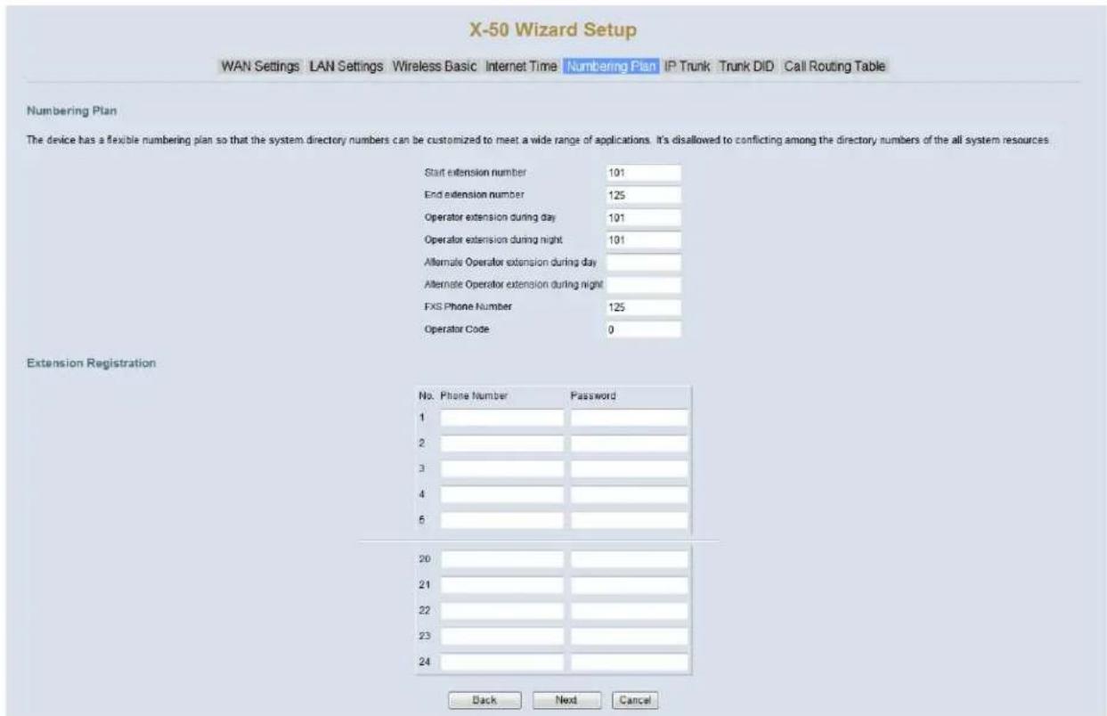
text_image
X-50 Wizard Setup WAN Settings LAN Settings Wireless Basic Internet Time Numbering Plan IP Trunk Trunk DID Call Routing Table Numbering Plan The device has a flexible numbering plan so that the system directory numbers can be customized to meet a wide range of applications. It's disallowed to conflicting among the directory numbers of the all system resources Start extension number 101 End extension number 125 Operator extension during day 101 Operator extension during night 101 Alternate Operator extension during day Alternate Operator extension during night FXS Phone Number 125 Operator Code 0 Extension Registration No. Phone Number Password 1 2 3 4 6 20 21 22 23 24 Back Next CancelThe numbering plan establishes the “dial plan” that will be used for the X-50 system. It defines the start extension number (101) and the ending extension number (125), as well as the day and night operator extension or extensions. In addition, the X-50 includes one FXS (Single Line - analog - Telephone) which has a default number of 125 and the number to be dialed to ring the operator (0); all of which can be customized.
The SIP Authentication area is where the extension telephone numbers and passwords are established. These numbers are used by the SIP telephone endpoints to authenticate to the X-50 system. It is important to keep in mind if this system is going to be part of a larger voice network, the whole network must have one unified numbering plan. For example, a system in Boston may have extensions numbered 1001 - 1025, in Chicago 1501 - 1525, Las Vegas 2001 - 2025 and in San Francisco 3001 - 3025, etc. This will allow an extension to dial 4 digits (3 digits number plans will also work) and speak to someone at a different location. For example, someone in Boston dials 2021 and speaks to an extension user in Las Vegas without using a telephone line. Tables “Suggested 4-Digit Numbing Plan” on page 92 and “Suggested 3-Digit Numbing Plan” on page 93 show some suggestions extension numbering plans.
Note:
When entering a new numbering plan do not use 311, 411 and 911 as extension numbers.
TABLE 6.1 Suggested 4-Digit Numbing Plan
| Single System Voice Network Numbering Plan | |||||||||||
| A | I | p | n | e | P | $ | W | D | 1 | 2 | 3 |
| Primary | |||||||||||
| 101 10110 | 1 1001 1501 | 2001 3001 4 | 001 5001 6 | 001 7001 8 | 001 9001 | ||||||
| 102 10210 | 2 1002 1502 | 2002 3002 4 | 002 5002 6 | 002 7002 8 | 002 9002 | ||||||
| 103 10310 | 3 1003 1503 | 2003 3003 4 | 003 5003 6 | 003 7003 8 | 003 9003 | ||||||
| 104 10410 | 4 1004 1504 | 2004 3004 4 | 004 5004 6 | 004 7004 8 | 004 9004 | ||||||
| 105 10510 | 5 1005 1505 | 2005 3005 4 | 005 5005 6 | 005 7005 8 | 005 9005 | ||||||
| 106 10610 | 6 1006 1506 | 2006 3006 4 | 006 5006 6 | 006 7006 8 | 006 9006 | ||||||
| 107 10710 | 7 1007 1507 | 2007 3007 4 | 007 5007 6 | 007 7007 8 | 007 9007 | ||||||
| 108 10810 | 8 1008 1508 | 2008 3008 4 | 008 5008 6 | 008 7008 8 | 008 9008 | ||||||
| 109 10910 | 9 1009 1509 | 2009 3009 4 | 009 5009 6 | 009 7009 8 | 009 9009 | ||||||
| 110 11011 | 10 1010 1510 | 2010 3010 4 | 010 5010 6 | 010 7010 8 | 010 9010 | ||||||
| 111 11111 | 11 1011 1511 | 2011 3011 4 | 011 5011 6 | 011 7011 8 | 011 9011 | ||||||
| 112 11211 | 12 1012 1512 | 2012 3012 4 | 012 5012 6 | 012 7012 8 | 012 9012 | ||||||
| 113 11311 | 13 1013 1513 | 2013 3013 4 | 013 5013 6 | 013 7013 8 | 013 9013 | ||||||
| 114 11411 | 14 1014 1514 | 2014 3014 4 | 014 5014 6 | 014 7014 8 | 014 9014 | ||||||
| 115 11511 | 15 1015 1515 | 2015 3015 4 | 015 5015 6 | 015 7015 8 | 015 9015 | ||||||
| 116 11611 | 16 1016 1516 | 2016 3016 4 | 016 5016 6 | 016 7016 8 | 016 9016 | ||||||
| 117 11711 | 17 1017 1517 | 2017 3017 4 | 017 5017 6 | 017 7017 8 | 017 9017 | ||||||
| 118 11811 | 18 1018 1518 | 2018 3018 4 | 018 5018 6 | 018 7018 8 | 018 9018 | ||||||
| 119 11911 | 19 1019 1519 | 2019 3019 4 | 019 5019 6 | 019 7019 8 | 019 9019 | ||||||
| 120 12012 | 20 1020 1520 | 2020 3020 4 | 020 5020 6 | 020 7020 8 | 020 9020 | ||||||
| 121 12112 | 21 1021 1521 | 2021 3021 4 | 021 5021 6 | 021 7021 8 | 021 9021 | ||||||
| 122 12212 | 22 1022 1522 | 2022 3022 4 | 022 5022 6 | 022 7022 8 | 022 9022 | ||||||
| 123 12312 | 23 1023 1523 | 2023 3023 4 | 023 5023 6 | 023 7023 8 | 023 9023 | ||||||
| 124 12412 | 24 1024 1524 | 2024 3024 4 | 024 5024 6 | 024 7024 8 | 024 9024 | ||||||
| 125 12512 | 25 1025 1525 | 2025 3025 4 | 025 5025 6 | 025 7025 8 | 025 9025 | ||||||
TABLE 6.2 Suggested 3-Digit Numbing Plan
| Single System Voice Network Numbering Plan | |||||||||||
| A | I | o | n | e | P | S | W | D | 1 | 2 | 3 |
| Primary | |||||||||||
| 101 10110 | 1 101 151 2 | 01 301 401 5 | 01 601 701 | 801 901 | |||||||
| 102 10210 | 2 102 152 2 | 02 302 402 5 | 02 602 702 | 802 902 | |||||||
| 103 10310 | 3 103 153 2 | 03 303 403 5 | 03 603 703 | 803 903 | |||||||
| 104 10410 | 4 104 154 2 | 04 304 404 5 | 04 604 704 | 804 904 | |||||||
| 105 10510 | 5 105 155 2 | 05 305 405 5 | 05 605 705 | 805 905 | |||||||
| 106 10610 | 6 106 156 2 | 06 306 406 5 | 06 606 706 | 806 906 | |||||||
| 107 10710 | 7 107 157 2 | 07 307 407 5 | 07 607 707 | 807 907 | |||||||
| 108 10810 | 8 108 158 2 | 08 308 408 5 | 08 608 708 | 808 908 | |||||||
| 109 10910 | 9 109 159 2 | 09 309 409 5 | 09 609 709 | 809 909 | |||||||
| 110 11011 | 10 110 160 2 | 10 310 410 5 | 10 610 710 | 810 910 | |||||||
| 111 11111 | 11 111 161 2 | 11 312 412 5 | 11 611 711 | 811 912 | |||||||
| 112 11211 | 12 112 162 2 | 12 313 413 5 | 12 612 712 | 812 913 | |||||||
| 113 11311 | 13 113 163 2 | 13 314 414 5 | 13 613 713 | 813 914 | |||||||
| 114 11411 | 14 114 164 2 | 14 315 415 5 | 14 614 714 | 814 915 | |||||||
| 115 11511 | 15 115 165 2 | 15 316 416 5 | 15 615 715 | 815 916 | |||||||
| 116 11611 | 16 116 166 2 | 16 317 417 5 | 16 616 716 | 816 917 | |||||||
| 117 11711 | 17 117 167 2 | 17 318 418 5 | 17 617 717 | 817 918 | |||||||
| 118 11811 | 18 118 168 2 | 18 319 419 5 | 18 618 718 | 818 919 | |||||||
| 119 11911 | 19 119 169 2 | 19 320 420 5 | 19 619 719 | 819 920 | |||||||
| 120 12012 | 20 120 170 2 | 20 321 421 5 | 20 620 720 | 820 921 | |||||||
| 121 12112 | 21 121 171 2 | 21 322 422 5 | 21 621 721 | 821 922 | |||||||
| 122 12212 | 22 122 172 2 | 22 323 423 5 | 22 622 722 | 822 923 | |||||||
| 123 12312 | 23 123 173 2 | 23 324 424 5 | 23 623 723 | 823 924 | |||||||
| 124 12412 | 24 124 174 2 | 24 325 425 5 | 24 624 724 | 824 925 | |||||||
| 125 12512 | 25 125 175 2 | 25 326 426 5 | 25 625 725 | 825 965 | |||||||
- Day and Night Operator - at default the Single Line (Analog) Telephone, extension 125, is programmed to be the day and night operator.
- Operator speed dial is the number that will be dialed to ring the operator. Generally this is set to zero (0).
- Phone Number & passwords to authenticate each SIP telephone endpoint. Although, remote workers will automatically authenticate it is a good idea to manually enter the extension number and password of all remote workers. Because the WAN port authenticates first, remote workers may change their extension number when the system is reset.
SIP Trunks
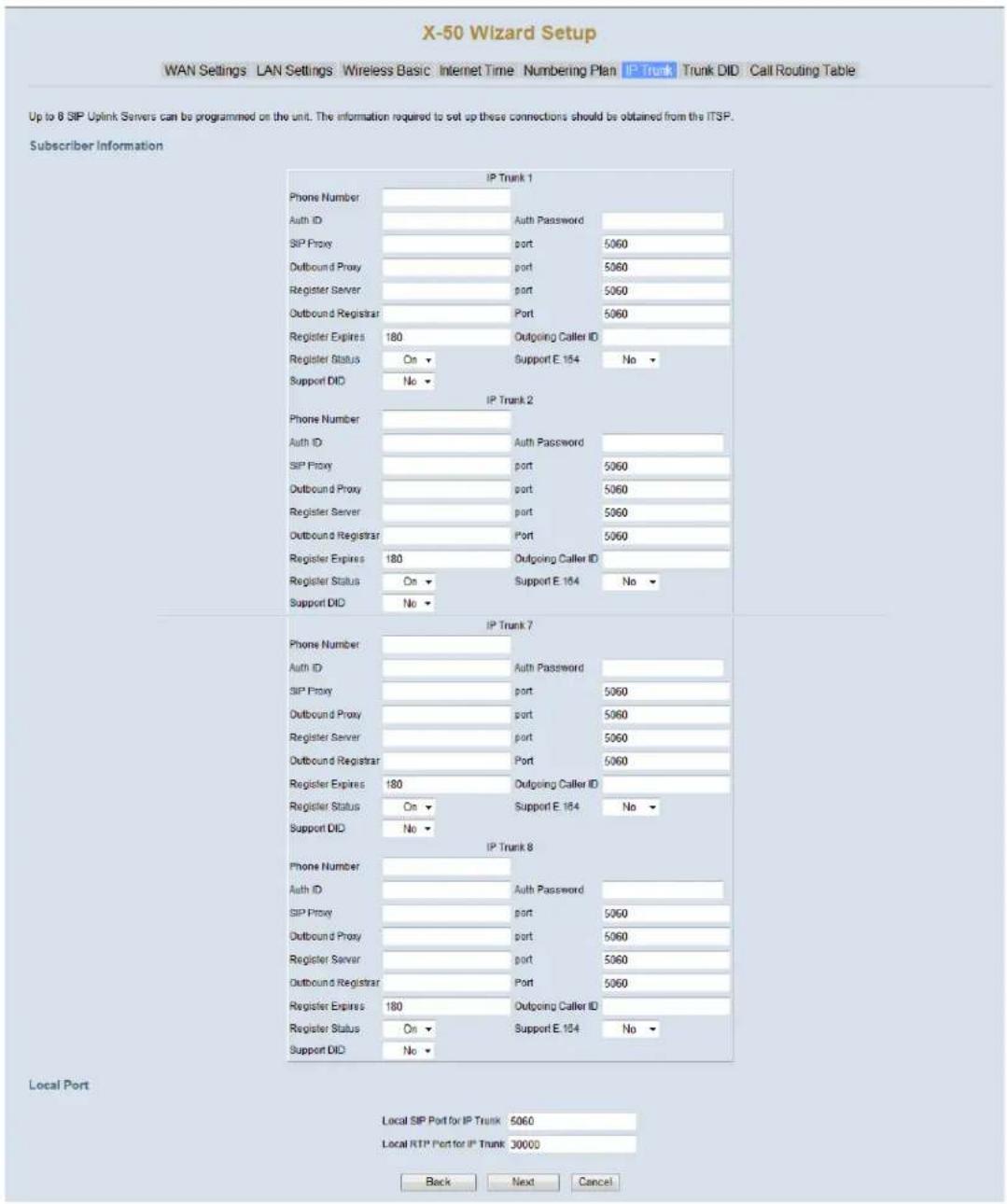
text_image
X-50 Wizard Setup WAN Settings LAN Settings Wireless Basic Internet Time Numbering Plan IP Trunk Trunk DID Call Routing Table Up to 8 SIP Uplink Servers can be programmed on the unit. The information required to set up these connections should be obtained from the ITSP. Subscriber Information IP Trunk 1 Phone Number Auth ID Auth Password SIP Proxy port 5060 Outbound Proxy port 5060 Register Server port 5060 Outbound Registrar Port 5060 Register Expires 180 Outgoing Caller ID Register Status On Support E 184 No Support DID No IP Trunk 2 Phone Number Auth ID Auth Password SIP Proxy port 5060 Outbound Proxy port 5060 Register Server port 5060 Outbound Registrar Port 5060 Register Expires 180 Outgoing Caller ID Register Status On Support E 184 No Support DID No IP Trunk 7 Phone Number Auth ID Auth Password SIP Proxy port 5060 Outbound Proxy port 5060 Register Server port 5060 Outbound Registrar Port 5060 Register Expires 180 Outgoing Caller ID Register Status On Support E 184 No Support DID No IP Trunk 8 Phone Number Auth ID Auth Password SIP Proxy port 5060 Outbound Proxy port 5060 Register Server port 5060 Outbound Registrar Port 5060 Register Expires 180 Outgoing Caller ID Register Status On Support E 184 No Support DID No Local Port Local SIP Port for IP Trunk 5060 Local RTP Port for IP Trunk 30000 Back Next CancelThe X-50 comes equipped to support eight SIP IP Trunks and fifty Direct Inward Dial (DID) numbers. SIP Trunks are not physically connected, they authenticate over the Internet. Thus, the voice quality of these line are directly related to the ISP speed. There are several SIP IP Trunk providers on the market and the integration should be standardized. However, this may not always be the case, and although we do our best to integrate all SIP Trunks, there is no guarantee, written or implied, that every SIP IP Trunk provider will work with the X-50.
The settings will be provided by the SIP IP Trunk Provider; please contact the provider if any adjustments are needed to integrate their SIP Trunk.
- Phone number - The assigned phone number which will be provided by the SIP IP Trunk provider.
- User Name - The SIP IP Trunk provider will provide the user name. Depending on the provider, the user name may be an account number, telephone number or reference number.
- Auth ID - Authentication ID - The SIP IP Trunk provider will provide the Authentication ID. Depending on the provider, the Auth ID may be an account number, telephone number or reference number.
- Auth Password - Authentication Password - The SIP IP Trunk provider will provide the Authentication Password. Depending on the provider, the Auth Password may be an account number, telephone number or reference number.

text_image
ClueA Proxy Server is a "Go Between" that makes request on behalf of other clients. Its primary roll is to route packets the fastest way possible and enforce routing policies, even if it has to rewrite specific parts of the request before forwarding the packet.
A Register Server sends a Registrar Server requests so that it will place vital information in a location for the Domain Server. Some SIP IP Trunk providers require that a Registrar Server be reference in order to keep the connection working correctly.
An Outbound Proxy is often used as a central location for security verification before connecting two devices. This is commonly used as an additional layer of security.
- SIP Proxy - The SIP IP Trunk Provider will provide the SIP Proxy. The SIP Proxy can be either a class A or B IP Address, or must likely will be a specific Uniform (Universal) Resource Locator (URL) Address.
- Port - 5060 is one of the "Well Known Ports" that is used for the transmission of both TCP or UDP SIP Packets. Some providers may require this to be changed, but most will not.
- Outbound Proxy - The SIP IP Trunk Provider will provide the Outbound Proxy. The Outbound Proxy's Address can be either a class A or B IP Address, or must likely will be a specific Uniform (Universal) Resource Locator (URL) Address.
- Port - 5060 is one of the “Well Known Ports” that is used for the transmission of both TCP or UDP SIP Packets. Some providers may require this to be changed, but most will not.
- Register Server - The SIP IP Trunk Provider will provide the Registrar Server. The Registrar Server's address can be either a class A or B IP Address, or must likely will be a specific Uniform (Universal) Resource Locator (URL) Address.
- Port - 5060 is one of the “Well Known Ports” that is used for the transmission of both TCP or UDP SIP Packets. Some providers may require this to be changed, but most will not.
- SIP Domain - The SIP IP Trunk Provider will provide the SIP Domain. The SIP Domain can be either a class A or B IP Address, or must likely will be a specific Uniform (Universal) Resource Locator (URL) Address.
- Register Expires - If "Register Status" is set to "On" this timer will be referenced and it is how often the X-50 will send a signal to the Registrar Server in order to keep the information current. If there is no reply within the programmed time, at default 60 seconds, the connection is terminated.
- Register Status - When Set to "On" the Register Expires will be referenced, otherwise it will not be referenced. The SIP IP Trunk provider will provide the proper settings for this parameter.
- Support E.164 - This protocol was defined by ITU-T, to standardize international telecommunications numbering plan, used over the Public Switched Telephone Network (PSTN). For proper dialing formats, some SIP IP Trunk Providers may require this to be enabled. At default, it is disabled.
Direct Inward Dial (DID)
X-50 Wizard Setup
WAN Settings LAN Settings Wireless Basic Internet Time Numbering Plan IP Trunk Trunk DID Call Routing Table
DID Table
| No. | DID Number | Destination | Outgoing Call ID | Display Name | Trunk |
| 1 | Group 2 ▼ | ||||
| 2 | Group 2 ▼ | ||||
| 3 | Group 2 ▼ | ||||
| 4 | Group 2 ▼ | ||||
| 5 | Group 2 ▼ | ||||
| 6 | Group 2 ▼ | ||||
| 7 | Group 2 ▼ | ||||
| 8 | Group 2 ▼ | ||||
| 9 | Group 2 ▼ | ||||
| 45 | Group 2 ▼ | ||||
| 46 | Group 2 ▼ | ||||
| 47 | Group 2 ▼ | ||||
| 48 | Group 2 ▼ | ||||
| 49 | Group 2 ▼ | ||||
| 50 | Group 2 ▼ |

- DID Number - Enter the DID numbers that will be received from the SIP Trunks.
- Destination - Enter the destination of the receiving DID number, valid entries are a physical, virtual extension or a UCD group.
- Outgoing Caller ID - Enter the telephone number that the SIP Trunk will send when the entered DID extension makes an outgoing call.
- Display Name - Enter the name that the SIP Trunk will send when the entered DID extension makes an outgoing call.
Call Routing Table
X-50 Wizard Setup
WAN Settings LAN Settings Wireless Basic Internet Time Numbering Plan IP Trunk Trunk DID Call Routing Table
Call Routing Table Configuration
The Call Routing Table automatically routes outgoing calls using the most appropriate route. The appropriate route is determined based on the number dialed. If necessary, the unit can automatically modify the dialod number by deleting and/or inserting digits.
| No. | From | To | Min | Max | Del | Insert | Destination |
| 1 | 0 | # | 1 | 99 | 0 | Group 1 ▼ | |
| 2 | 1 | 99 | 0 | PSTN Line 1 ▼ | |||
| 3 | 1 | 99 | 0 | PSTN Line 1 ▼ | |||
| 4 | 1 | 99 | 0 | PSTN Line 1 ▼ | |||
| 5 | 1 | 99 | 0 | PSTN Line 1 ▼ | |||
| 6 | 1 | 99 | 0 | PSTN Line 1 ▼ | |||
| 7 | 1 | 99 | 0 | PSTN Line 1 ▼ | |||
| 8 | 1 | 99 | 0 | PSTN Line 1 ▼ | |||
| 9 | 1 | 99 | 0 | PSTN Line 1 ▼ | |||
| 10 | 1 | 99 | 0 | PSTN Line 1 ▼ | |||
| 35 | 1 | 99 | 0 | PSTN Line 1 ▼ | |||
| 36 | 1 | 99 | 0 | PSTN Line 1 ▼ | |||
| 37 | 1 | 99 | 0 | PSTN Line 1 ▼ | |||
| 38 | 1 | 99 | 0 | PSTN Line 1 ▼ | |||
| 39 | 1 | 99 | 0 | PSTN Line 1 ▼ | |||
| 40 | 1 | 99 | 0 | PSTN Line 1 ▼ |

Once programmed, the Call Routing Table will automatically route calls through the proper telephone line or group of lines (line group). Each entry may contain up to ten digits and has a "From" (start evaluation) and a "To" (end evaluation) digit or set of digits. In addition, dialed numbers can be automatically modified to ensure that they are sent through the most cost effective route. For example, if the main number of another system on the voice network is dialed, that number can be deleted, and a new number can be inserted. The Call Routing Tables are also used to direct three or four digit dialing between X-50 VoIP Telephone Systems.

text_image
ClueFor proper operation of Call Log - Dialed, Missed, and Received Calls, the home area code, and automatic long distance insert, must be programmed into the Call Routing Table.
Enter the home area code, where the system is located, such as 913 in the "From" and "To", then the maximum and minimum digits dialed will be 10, in both, then enter 3 digits to be deleted by the system before the number is dialed. Do not enter any digits into the "Delete" parameter if all 10 digits should be dialed. Therefore, when a number in the entered area code is dialed, the area code if there is an entry in the delete parameter, in the example, 913, will be delete. The remaining 7 digits will be dialed.
The second entry will automatically enter a 1 for all other 10 digit numbers. Enter "From 2", "To 9", Min=10, Max=10, Insert=1, and "Group" default is 1. When any number that begins with 2 through 9, except 913, will receive a 1, when it is sent to the telephone line.
Kansas
| No. | From | To | Min | Max | Del | Insert | Destination | IGW Group | Remove | Edit | Change Order |
| 1 | 913 | 913 | 10 | 10 | 3 | Group 1 | Edit | Up Down | |||
| 2 | 2 | 9 | 10 | 10 | 0 | 1 | Group 1 | Edit | Up Down | ||
| 3 | 0 | # | 1 | 99 | 0 | Group 1 | Edit | Up Down |
In Scottsdale Arizona, for example, any 10 digit number that is dialed with 480 as the first three digits, 480 will be deleted. Any 10 digit number that has 602 and 623 as an area code, all 10 digits will be dialed. All other 10 digit numbers regardless of area code will receive a 1 before sending the call to the telephone line.
Scottsdale, AZ
| No. | From | To | Min | Max | Del | Insert | Destination | IGW Group | Remove | Edit | Change Order |
| 1 | 480 | 480 | 10 | 10 | 3 | Group 1 | Edit | Up Down | |||
| 2 | 602 | 602 | 10 | 10 | 0 | Group 1 | Edit | Up Down | |||
| 3 | 623 | 623 | 10 | 10 | 0 | Group 1 | Edit | Up Down | |||
| 4 | 2 | 9 | 10 | 10 | 0 | 1 | Group 1 | Edit | Up Down | ||
| 5 | 0 | # | 1 | 99 | 0 | Group 1 | Edit | Up Down |
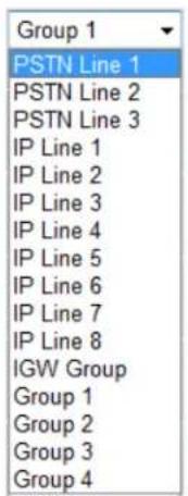
text_image
Group 1 PSTN Line 1 PSTN Line 2 PSTN Line 3 IP Line 1 IP Line 2 IP Line 3 IP Line 4 IP Line 5 IP Line 6 IP Line 7 IP Line 8 IGW Group Group 1 Group 2 Group 3 Group 4Calls can automatically be routed to a specific telephone (PSTN) or Group of lines, a specific SIP IP Trunk or group of SIP IP Trunks or to another X-50.
Using the routing table eliminates the need for users to remember, what can be, complex dialing plans.
- The "From" entry, works in conjunction with the "To" entry, and where the digit evaluation begins. This entry can contain up to ten digits. When a dialed number falls within the "From" and the "To" entries the call will be routed through the programmed destination.

text_image
ClueThe "To" entry must be a greater number than the "From" entry, or the rule will be invalid.
- The "To" entry, works in conjunction with the "From" entry, and where the digit evaluation ends. This entry can contain up to ten digits. When a dialed number falls within the "From" and the "To" entries the call will be routed through the programmed destination.
- The "Min" entry, works in conjunction with the "Max" entry, and determines the minimum number of digits required to be considered for evaluation.
- The "Max" entry, works in conjunction with the "Min" entry, and determines the maximum number of digits that will be evaluated. Any digits that exceeds this number will not be evaluated.
- The "del" (delete digits) column is the number of digits that will be deleted when the dialed digits match the "From" and the "To" entry.
- The maximum number of digits that can be inserted, from the insert column is ten.
- Calls can be routed to a specific telephone line, 1 through 6, a SIP IP Line, 1 through 8, between other X-50 systems using the IGW group, or a group can be created using either telephone lines or SIP IP Trunk Lines, or a combination of both.
Programming Wizard
Complete the Setup Wizard by selecting the "Save & Reboot" to save the changes or "Exit & Reboot" to discard the changes. Select the "Back" button to modify any parameters that may need to be changed before completing the wizard.

text_image
Back Save & Reboot Exit & Reboot Done Internet | Protected Mode: Off 100%7 Advanced Programming
Advanced Programming
Using an Internet browser enter the X-50 VoIP Telephone System's IP Address. The default LAN IP Address is set to 192.168.10.1.
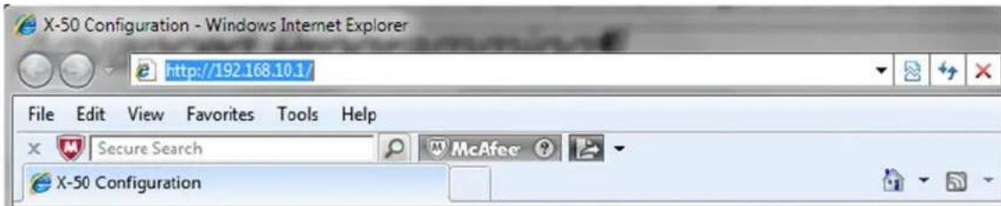
text_image
X-50 Configuration - Windows Internet Explorer http://192.168.10.1/ File Edit View Favorites Tools Help Secure Search McAfee X-50 ConfigurationThis will bring up the Login window
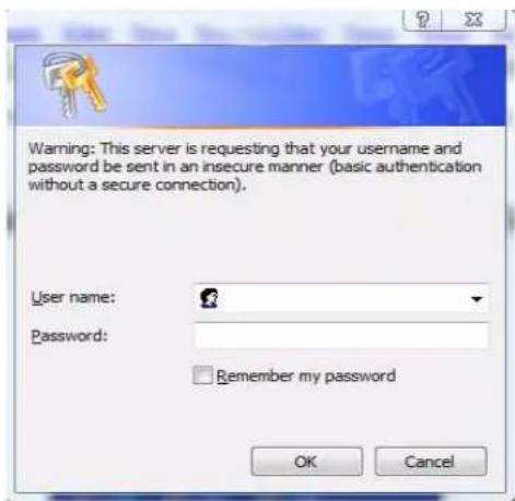
text_image
Warning: This server is requesting that your username and password be sent in an insecure manner (basic authentication without a secure connection). User name: Password: Remember my password OK CancelThe default login is: admin2583
The default Password is: 000000
There are eight major sections that make up the programming parameters of the X-50 VoIP Telephone System. Two sections, "Device Info", which shows current network status of the gateway and "Diagnostics", which shows WAN/LAN, Wireless, Pinging the Default Gateway and the DNS station as well as the current status of the FXO - Telephone Lines, SIP IP Trunks, the Auto Attendant Ports, and the FXS - Single Line Telephone.
• Device Info
- Advanced Setup
- Wireless
• +Voice
- Management
• Diagnostics
- Logout
Device Information
- Device Info
- Summary
- Statistics
- LAN
- WAN
- Route
- ARP
- DHCP
Device Information Introduction
The parameters contained within the Device Information section is for reference only, showing statistical information, about the hardware and software, of the X-50 VoIP Telephone System.

text_image
ClueThe "Device Info" page is a quick way to determine the current status of the X-50, and a great troubleshooting tool. However, these pages are only for reference, nothing can be changed or programmed.
This page shows the software versions and the hardwares' physical addresses as well as the LAN and WAN port IP Addresses and the Date & time.
Device Information

X-50 Configuration
text_image
Device Info - Summary - Statistics - LAN - WAN - Route - ARP - DHCP Advanced Setup Wireless Voice Management Diagnostics LogoutDevice Info
| Software Version: | V0.8.4 |
| Bootloader (CFE) Version: | 1.0.37-10.2.11 |
| Wireless Driver Version: | 5.10.120.0.cpe4.402.9 |
| Serial Number: | TECOM_IG6600_016 |
| MAC Address: | 00:10:15:B0:DA:22 |
| System Up Time: | 0 days, 8 hours, 43 minutes |
LAN Info
| LAN IP Address: | 192.168.10.1 |
| Subnet mask | 255.255.255.0 |
| WLAN SSID (Primary): | XBN-GW-B9DA22 |
WAN Info
| WAN IP Address: | 192.168.1.244 |
| Default Gateway: | 192.168.1.254 |
| Primary DNS Server: | 68.94.156.1 |
| Secondary DNS Server: | 68.94.157.1 |
| Type: | Static |
| IGMP Status: | Disabled |
| Firewall Status: | Disabled |
| Connection Status: | Connected |
Date / Time
| Tuesday, 30 November 2010, 21:46:47 |
The current settings for the LAN and WAN ports are found in the Statistics folder. These Pages show how many packets have been received and transmitted. This information is invaluable when troubleshooting.
LAN

X-50 Configuration
Device Info
Summary
Statistics
-LAN
WAN
- Route
ARE
OHCP
Advanced Setup
Wireless
Voice
Management
Diagnostics
Logout
Statistics -- LAN
| Interface | Received | Transmitted | ||||||
| Bytes | Packets | Errors | Drops | Bytes | Packets | Errors | Drops | |
| LAN | 1369632 | 4199 | 0 | 0 | 4148095 | 7726 | 0 | 0 |
| WLAN | 10884 | 55 | 0 | 0 | 3016021 | 3877 | 32 | 0 |
Reset Statistics
WAN port statistics.
WAN
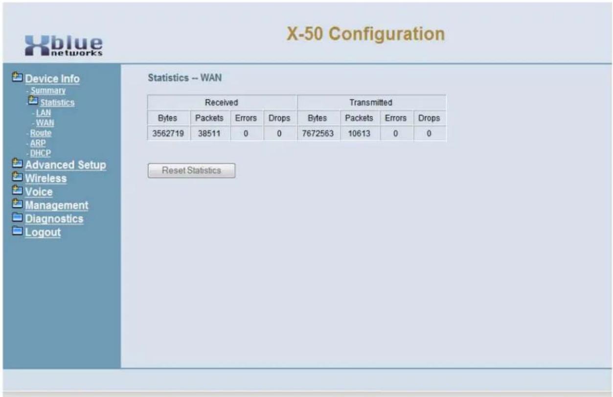
text_image
X-50 Configuration Device Info - Summary Statistics -LAN -WAN - Route - ARP -DHCP Advanced Setup Wireless Voice Management Diagnostics Logout Statistics -- WAN Received Transmitted Bytes Packets Errors Drops Bytes Packets Errors Drops 3562719 38511 0 0 7672563 10613 0 0 Reset StatisticsThe Route table shows the destination, Gateway and Subnet Mask IP Addresses as well as the Flag, metric and Interface.

X-50 Configuration
text_image
Device Info - Summary Statistics -LAN -WAN -Route -ARP -DHCP Advanced Setup Wireless Voice Management Diagnostics LogoutDevice Info -- Route
Flags: U - up, ! - reject, G - gateway, H - host, R - reinstate D - dynamic (redirect), M - modified (redirect).
| Destination | Gateway | Subnet Mask | Flags | Metric | Interface |
| 192.168.1.0 | 0.0.0.0 | 255.255.255.0 | U | 0 | WAN |
| 192.168.1.0 | 192.168.1.254 | 255.255.255.0 | UG | 1 | WAN |
| 192.168.10.0 | 0.0.0.0 | 255.255.255.0 | U | 0 | LAN |
| 0.0.0.0 | 192.168.1.254 | 0.0.0.0 | UG | 0 | WAN |
| Flags Meaning | |||
| U | Up | ||
| ! Rejected | |||
| G | G | a | t |
| H | H | o | s |
| R Reinstate | |||
| D | D | y | n |
| M Modified (Redirect) | |||
e w a y
t
a m i c
- Interface - Type of connection - LAN or WAN
The Address Resolution Protocol (ARP) table is where the X-50 catalogs the IP address of a device with its physical Hardware (MAC) address. In addition, this page shows which device (LAN or WAN) is using the specific IP Address.
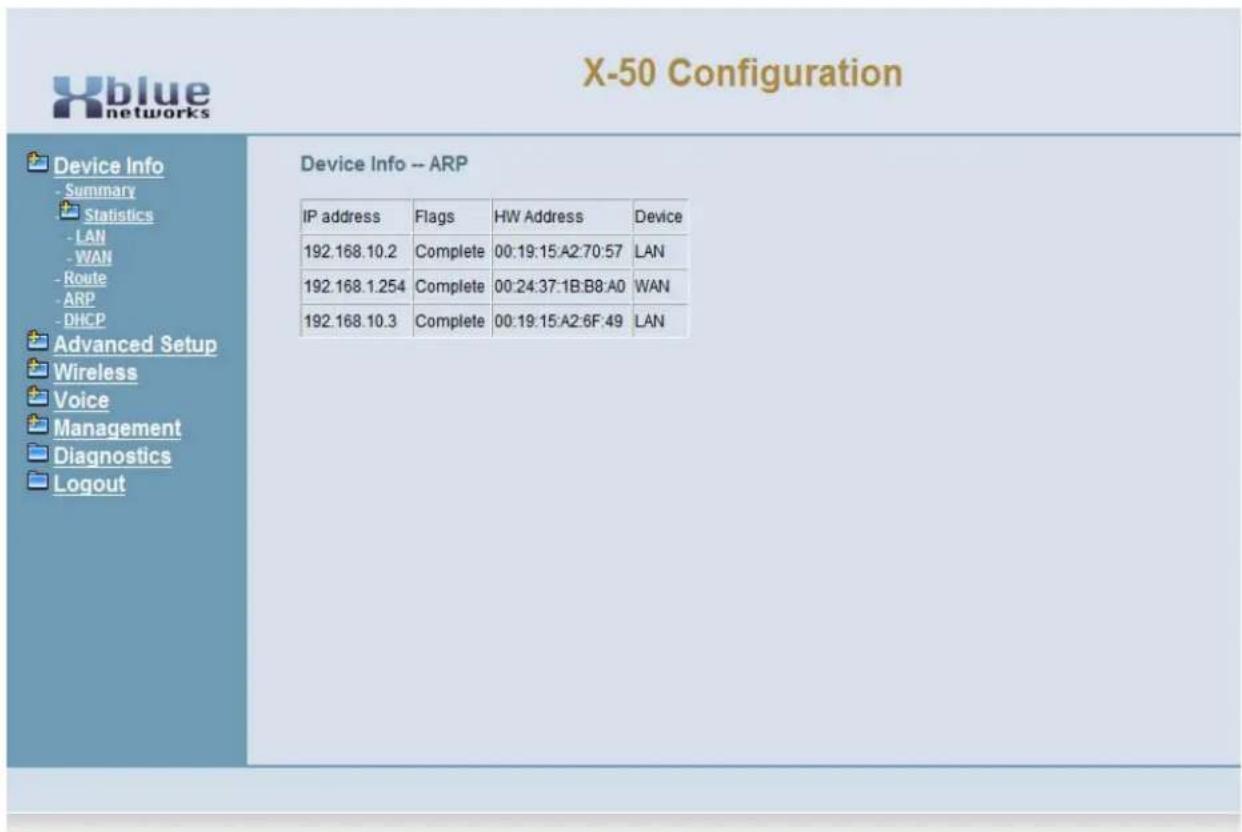
text_image
X-50 Configuration Device Info -- ARP IP address Flags WH Address Device 192.168.10.2 Complete 00:19:15:A2:70:57 LAN 192.168.1.254 Complete 00:24:37:1B:B8:A0 WAN 192.168.10.3 Complete 00:19:15:A2:6F:49 LAN- IP Address - Shows the IP Address of the device connected to the X-50 system.
- Flags - Identifies when the device is connecting and once it is connected.
- HW Address - Shows the MAC Address of the device connecting to the X-50 system.
• Device - Shows if the device is connected using a LAN or a WAN port.
The Dynamic Host Configuration Protocol (DHCP) table shows how many devices are connected to the X-50 VoIP Telephone System. In addition, it shows the MAC Address, IP Address, and the remaining length of the lease.
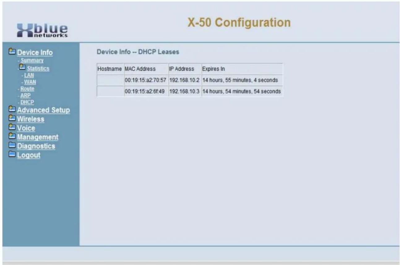
text_image
X-50 Configuration Device Info -- DHCP Leases Hostname MAC Address IP Address Expires In 00:19:15:a2:70:57 192.168.10.2 14 hours, 55 minutes, 4 seconds 00:19:15:a2:6f:49 192.168.10.3 14 hours, 54 minutes, 54 seconds- Host Name - The "name" of the device connected to the network.
• MAC Address - The physical address of the device connected to the network. - IP Address - The IP address of the device connected to the network.
- Expires In - The length of time left on the current device's lease.
Advanced Setup - WAN
- Device Info
- Advanced
- WAN
- LAN
- NAT
- Parental Control
• - Quality of Service - Routing
- Dynamic DNS
Advanced - WAN
Wide Area Network
At default, the WAN Port is set to Automatic Configuration - DHCP. Dynamic Host Control Protocol (DHCP) allows the WAN Port of the X-50 to automatically receive an IP and Subnet Mask Address as well as locate and join the network's default gateway or router. However, this may have been changed during the Setup Wizard. At default, the WAN port can be set to Automatic Configuration - DHCP, but it could be set to Static IP or PPPoE.
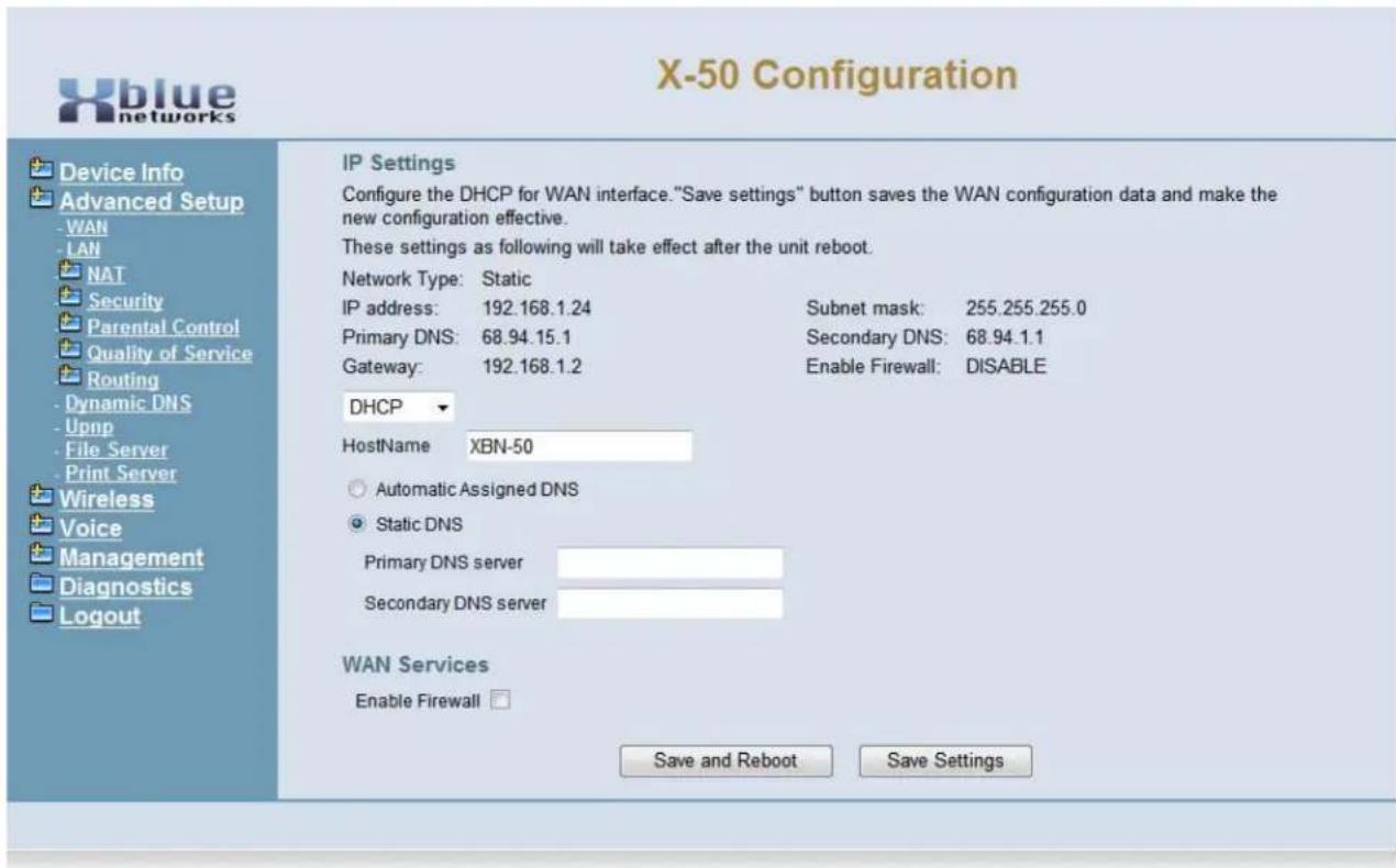
text_image
X-50 Configuration Device Info Advanced Setup -WAN -LAN NAT Security Parental Control Quality of Service Routing -Dynamic DNS -Upnp -File Server -Print Server Wireless Voice Management Diagnostics Logout IP Settings Configure the DHCP for WAN interface. "Save settings" button saves the WAN configuration data and make the new configuration effective. These settings as following will take effect after the unit reboot. Network Type: Static IP address: 192.168.1.24 Subnet mask: 255.255.255.0 Primary DNS: 68.94.15.1 Secondary DNS: 68.94.1.1 Gateway: 192.168.1.2 Enable Firewall: DISABLE DHCP HostName XBN-50 Automatic Assigned DNS Static DNS Primary DNS server Secondary DNS server WAN Services Enable Firewall Save and Reboot Save SettingsIP Settings (Default)
- At default, the "WAN Port Settings" are set to Automatic Configuration - Dynamic Host Control Protocol (DHCP), which allows the WAN port of the system to automatically receive an IP and Subnet Mask Address as well as locate and join the network's default gateway or router.
- The Host Name will be broadcast on the network and used by Dynamic Name Service (DNS).
- The system can use either dynamic (automatically assigned) or Static DNS settings. Unless required by the ISP, it is probably easier to leave this set to automatic.
WAN Services
- Enable Firewall - Although nothing is 100% safe against malicious network attacks, keeping the firewall enabled, will minimize the effectiveness of these attacks.
IP Settings (Static IP Address)

text_image
X-50 Configuration Device Info Advanced Setup WAN LAN NAT Security Parental Control Quality of Service Routing Dynamic DNS Upnp File Server Print Server Wireless Voice Management Diagnostics Logout IP Settings Configure the IP Address and Subnet Mask for WAN interface. "Save settings" button saves the WAN configuration data and make the new configuration effective. These settings as following will take effect after the unit reboot. Network Type: Static IP address: 192.168.1.24 Subnet mask: 255.255.255.0 Primary DNS: 68.94.15.1 Secondary DNS: 68.94.1.1 Gateway: 192.168.1.2 Enable Firewall: DISABLE Static IP ▼ IP Address: 192.168.1.24 Subnet Mask: 255.255.255.0 Gateway: 192.168.1.2 Static DNS 1: 68.94.15.1 Static DNS 2: 68.94.1.1 WAN Services Enable Firewall □ Save and Reboot Save SettingsThe WAN IP settings can be set to "Static IP Address", which allows the administrator to enter a specific IP Address for the X-50. Network administrators often reserve specific IP Addresses for servers, routers, and gateways. In addition, when using a static IP address, it is easier to connect to the X-50 for programming, especially when programming through Network Address Translation (NAT).
- Internet IP Address - enter the IP address that will be used to identify the X-50.
- Subnet Mask - when using the "Static IP Address" setting, the Subnet Mask will have to be manually entered. If there is a single Subnet, the entry will be 255.255.255.0. For more information about Subnet Masks refer to "Subnet Maks" on page 249
- Gateway - The default gateway refers to the Gateway device that connects the Intranet, to the Internet. Basically, it is the window to the Internet.
- Static DNS 1 & 2 - The Static DNS address maybe required by the Internet Service Provider (ISP). If not, the default gateway address can be used.
WAN Services
- Enable Firewall - Although nothing is 100% safe against malicious network attacks, keeping the firewall enabled, will minimize the effectiveness of these attacks.
Point-to-Point Protocol over Ethernet (PPPOE)
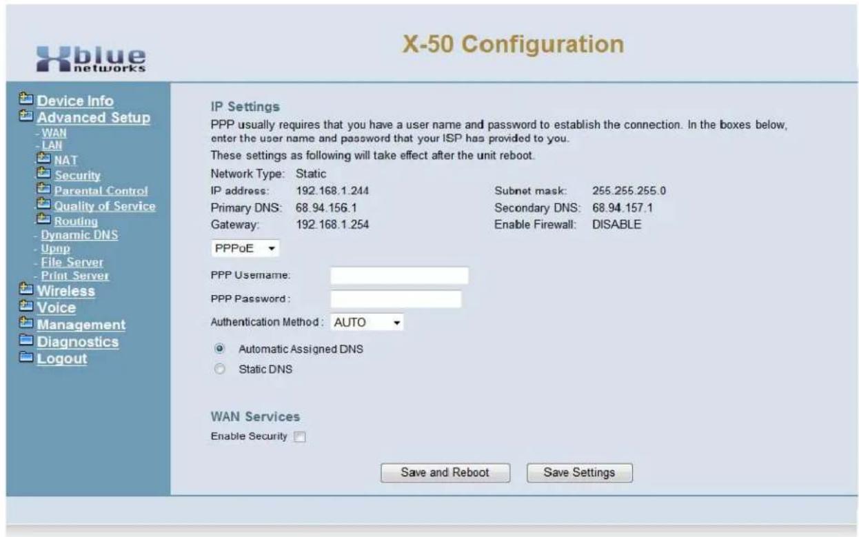
text_image
X-50 Configuration Device Info Advanced Setup - WAN - LAN NAT Security Parental Control Quality of Service Routing - Dynamic DNS - Upnp - File Server - Print Server Wireless Voice Management Diagnostics Logout IP Settings PPP usually requires that you have a user name and password to establish the connection. In the boxes below, enter the user name and password that your ISP has provided to you. These settings as following will take effect after the unit reboot. Network Type: Static IP address: 192.168.1.244 Subnet mask: 255.255.255.0 Primary DNS: 68.94.156.1 Secondary DNS: 68.94.157.1 Gateway: 192.168.1.254 Enable Firewall: DISABLE PPPoE PPP Username: PPP Password: Authentication Method: AUTO Automatic Assigned DNS Static DNS WAN Services Enable Security Save and Reboot Save SettingsThe WAN Port of the X-50 can also be set to PPPoE. In this case, the Internet Service Provider (ISP) will supply the administrator with a specific User Name and Password (most likely it will be case sensitive), which is required when connect the WAN port to the Internet.
• Automatic (Auto) - This will automatically negotiate the correct authentication protocol.
- Password Authentication Protocol (PAP) - This will send the authentication un-encrypted.
- Challenge Handshake Authentication (CHAP) - This is more secure than the aforementioned PAP, and sends the authentication encrypted.
- Microsoft's version of CHAP that allows mutual authentication between peers, by piggybacking challenge and response packets on a successful packet.
- Static DNS 1 & 2 - The Static DNS address maybe required by the Internet Service Provider (ISP). If not, the default gateway address can be used.
WAN Services
- Enable Firewall - Although nothing is 100% safe against malicious network attacks, keeping the firewall enabled, will minimize the effectiveness of these attacks.
Local Area Network (LAN)
When the X-50 comes on line the Local Area Network (LAN) IP Address will be set to "192.168.10.1" and the Subnet Mask will be set to "255.255.255.0". However, this may have been changed during the Setup Wizard.
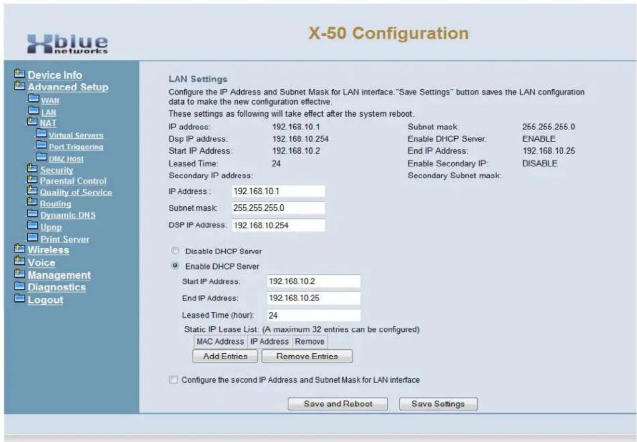
text_image
X-50 Configuration Device Info Advanced Setup WAN LAN NAT Virtual Servers Port Triggering DMZ Host Security Parental Control Quality of Service Routing Dynamic: DNS Upnp Print Server Wireless Voice Management Diagnostics Logout LAN Settings Configure the IP Address and Subnet Mask for LAN interface. "Save Settings" button saves the LAN configuration data to make the new configuration effective. These settings as following will take effect after the system reboot. IP address: 192.168.10.1 Dstp IP address: 192.168.10.254 Start IP Address: 192.168.10.2 Leased Time: 24 Secondary IP address: IP Address: 192.168.10.1 Subnet mask: 255.255.255.0 DSP IP Address: 192.168.10.254 Disable DHCP Server Enable DHCP Server Start IP Address: 192.168.10.2 End IP Address: 192.168.10.25 Leased Time (hour): 24 Static IP Lease List: (A maximum 32 entries can be configured) MAC Address | IP Address | Remove Add Entries | Remove Entries Configure the second IP Address and Subnet Mask for LAN interface Save and Reboot | Save Settings
text_image
ClueThe X-50 system is a gateway, which joins two or more different types of networks together, such as WAN, LAN and PSTN. If the X-50 system is connected to the ISP through a bridge to allow for connecting to external devices. The LAN Address will be set to 192.168.10.1 and it is set to be the network's DHCP Server.
However, if the X-50 is only using email delivery and remote pro-
gramming then the WAN port can be set to join as a node or client on the existing Local Area Network.
When connecting the WAN port of the X-50 to an existing LAN, the LAN port of the X-50 must be given a different IP address such as (192.168.100.1). The LAN of the X-50 is then considered "Down Stream" from the existing LAN.
When establishing any network numbering plan, do not use the IP address x.x.x.254 because this address is reserved for the system's DSP and will cause erratic operation.
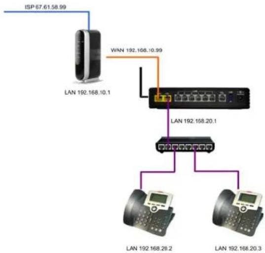
flowchart
graph TD
    A["ISP 67.61.58.99"] --> B["LAN 192.168.10.1"]
    C["WAN 192.168.10.99"] --> D["LAN 192.168.20.1"]
    D --> E["LAN 192.168.20.2"]
    D --> F["LAN 192.168.20.3"]
- LAN IP Address - at default the LAN IP Address is set to 192.168.10.1, but can be customized to accommodate any valid IP Address. In addition, it is considered the default gateway for any of the IP Telephone endpoints connected to the LAN ports.
- Subnet Mask - when using the "Static IP Address" setting, the Subnet Mask will have to be Manually entered. If there is a single Subnet, the entry will be 255.255.255.0. For more information about Subnet Masks refer to "Subnet Maks" on page 249
- DSP IP Address - The telephone system uses Digital Signal Processing to process standard telephony tones, which requires its own IP Address. Once assigned, no other device on the network can have the same IP Address, or the system will work erratically. The default IP Address is 192.168.10.254
- Universal Plug and Play (UPnP) - When enabled, the X-50 will recognize any device that is connected to the LAN port and begins broadcast UPnP protocol.
- Dynamic Host Configuration Protocol (DHCP) - When enabled the X-50 can be used to automatically assign client devices an IP Address. In addition, the administrator can grant a specific range of valid IP Addresses. At default the DHCP is enabled and will allow from 192.168.10.2 to 192.168.10.25. When disabled, every device connected to the network will have to be manually configured with an IP Address, which is good for security but creates a lot of extra work for the administrator.
- Leased Time - The amount of time that each dynamically assigned IP Address will be assigned to any one device before it is renewed. If the device is still connected and active, the device will probably continue with the same IP Address, otherwise it may be reassigned to another device.
Advanced - NAT
Network Address Translation (NAT)
- Device Info
- Advanced
- WAN
- LAN
- NAT
• Virtual Servers Setup - Port Triggering
• DMZ - Parental Control
• - Quality of Service - Routing
- Dynamic DNS
NAT reconciles the internal class "C" IP Addresses with the published Class "A" or "B" Static IP Addresses. It is this protocol that makes it possible to share one published Internet address with multiple internal LAN devices. NAT settings should be used carefully, because it may open the network up to malicious network attacks.

text_image
ClueRemote devices use NAT to gain access to internal devices. This protocol gives remote computers, like one at a home with an
IP Address of 192.168.10.20, access to a device in the office with an I address of
72.77.21.99. This gives remote locations the ability access and program a specific device, such as the X-50, from a remote location.
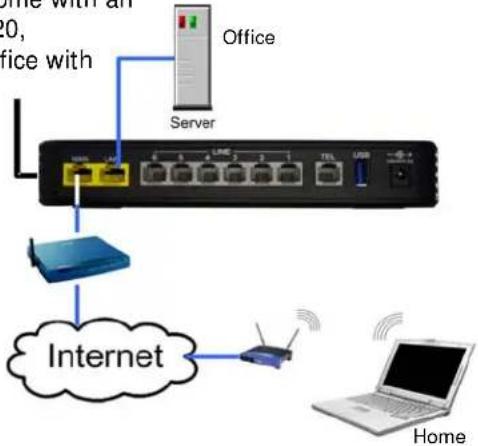
text_image
Home with an 20, office with Office Server Internet Home HomeVirtual Servers Setup
The Virtual Server parameter directs incoming TCP, UDP or both TCP/UDP, traffic from the WAN side of the connection, to a specific IP address on the LAN side. This is one way of directing incoming IP address data directly to a specific LAN device. This parameter is useful for remote access for Peer to Peer communication and games. The entered server's IP address is normally the computer or device on the LAN network that is running a specific application or game. When the WAN IP Address is presented to the X-50 system, the information is compared to this table and when a match is found, it will be redirected to entered internal IP address
Select Virtual Server Setup, and then select "Add" to add servers or "Remove" to remove servers from the current list.
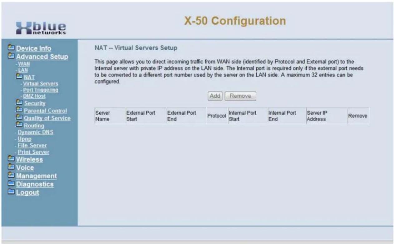
text_image
X-50 Configuration Device Info Advanced Setup -WAN -LAN NAT -Virtual Servers -Port Triggering -DMZ Host Security Parental Control Quality of Service Routing -Dynamic DNS -Upnp -File Server -Print Server Wireless Voice Management Diagnostics Logout NAT -- Virtual Servers Setup This page allows you to direct incoming traffic from WAN side (identified by Protocol and External port) to the Internal server with private IP address on the LAN side. The Internal port is required only if the external port needs to be converted to a different port number used by the server on the LAN side. A maximum 32 entries can be configured. Add Remove Server External Port External Port Protocol Internal Port Internal Port Server IP Name Start End End Start End End Address RemoveA maximum of 32 entries can be configured.

text_image
X-50 Configuration Device Info Advanced Setup WAN LAN NAT Virtual Servers Port Triggering DMZ Host Security Parental Control Quality of Service Routing Dynamic DNS Upnp File Server Print Server Wireless Voice Management Diagnostics Logout NAT -- Virtual Servers Setup Select the service name, and enter the server IP address and click "Apply/Save" to forward IP packets for this service to the specified server. NOTE: The "Internal Port End" cannot be modified directly. Normally, it is set to the same value as "External Port End".However, if you modify "Internal Port Start", then "Internal Port End" will be set to the same value as "Internal Port Start". Remaining number of entries that can be configured:32 Use Interface ipoe_eth2/eth2 Service Name: Select a Service: Windows 2000 Terminal Server Custom Service: Server IP Address: 192 168 10 191 Apply/Save External Port Start External Port End Protocol Internal Port Start Internal Port End 3389 3389 TCP 3389 3389 3389 3389 UDP 3389 3389 TCP TCP TCP TCP TCP TCP TCP TCP TCP TCP TCP TCP TCP TCP TCP TCP TCP TCP TCP TCP TCP TCP TCP TCP TCP TCP TCP TCP TCP TCP TCP TCP TCP TCP TCP TCP TCP TCP TCP TCP TCP TCP TCP TCP TCP TCP TCP TCP TCP TCP TPC TCP TCP TCP TCP TCP- Use Interface -
- Service Name - The administrator may create their own or use one of the of the preprogrammed commonly used services.
- Custom Service - If used, this required field allows the administrator to enter a name to be used for the custom service.
- Server IP Address - Enter the IP address of the "Server" or device that will receive the incoming TCP/UDP traffic.
- External Port Start - Enter the start port of the service to be directed to the entered Server IP Address.
- External Port End - Enter the end port of the service to be directed to the entered Server IP Address. This may be the same as the start port number.
- Protocol - Select the protocol to be used TCP, UDP or Both.
- Internal Port Start - This port should match the external Port Start entry
- Internal Port End - This Port should match the External Port End entry
NAT - Port Triggering
Port Triggering, unlike Virtual Servers which redirects a specific IP Address to a specific location, Port Triggering opens a port in the firewall allowing any IP Address, with the correct port in the address header, access into the system.
When an incoming port falls between the port start and the port end settings, and the protocol matches the associated protocol, the entered port start and port end will be opened, and directed to the open protocol. The trigger port end, cannot exceed 400 ports more than the trigger port start.
Select Port Triggering Setup and then select "Add" to add ports or "Remove" to remove ports from the current list.
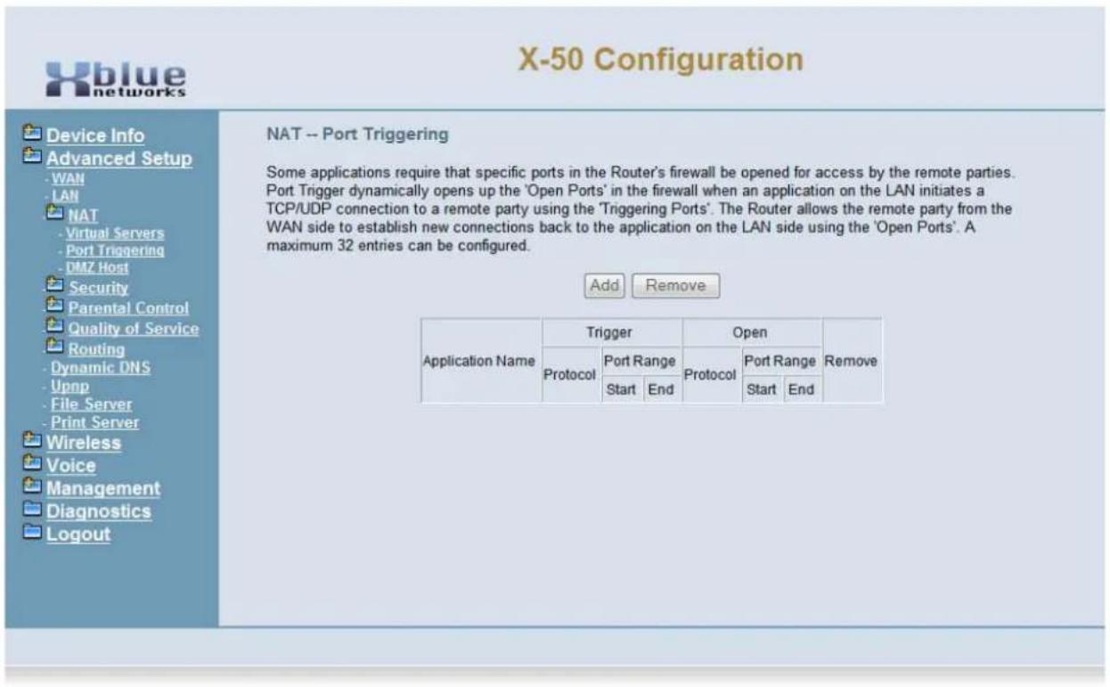
text_image
X-50 Configuration Device Info Advanced Setup WAN LAN NAT Virtual Servers Port Triggering DMZ Host Security Parental Control Quality of Service Routing Dynamic DNS Upnp File Server Print Server Wireless Voice Management Diagnostics Logout NAT -- Port Triggering Some applications require that specific ports in the Router's firewall be opened for access by the remote parties. Port Trigger dynamically opens up the 'Open Ports' in the firewall when an application on the LAN initiates a TCP/UDP connection to a remote party using the 'Triggering Ports'. The Router allows the remote party from the WAN side to establish new connections back to the application on the LAN side using the 'Open Ports'. A maximum 32 entries can be configured. Add Remove Application Name Trigger Open Remove Protocol Port Range Protocol Port Range Remove Start End Start EndNAT Port Triggering
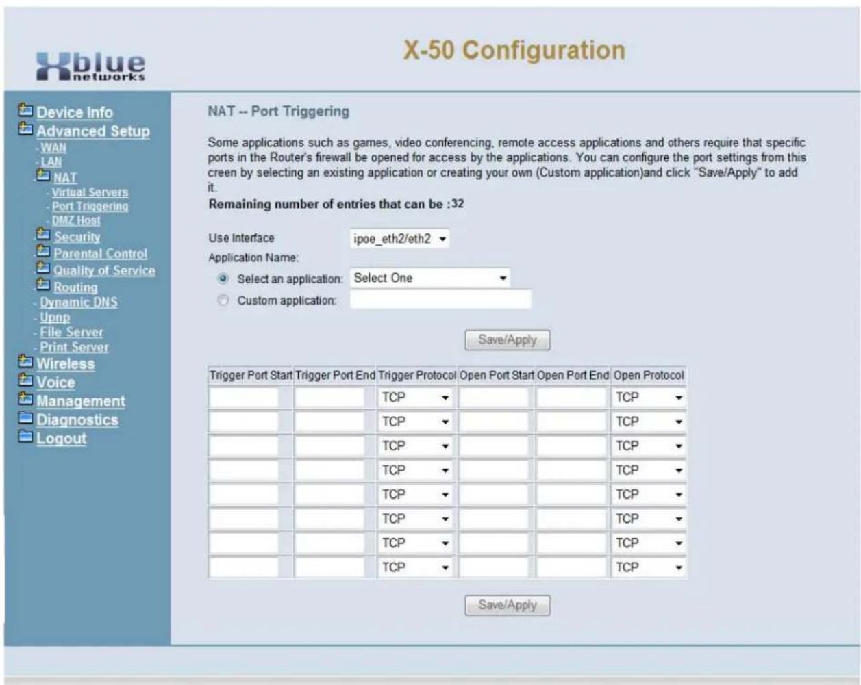
text_image
X-50 Configuration Device Info Advanced Setup -WAN -LAN NAT -Virtual Servers - Port Triggering - DMZ Host Security Parental Control Quality of Service Routing -Dynamic DNS -Upnp - File Server - Print Server Wireless Voice Management Diagnostics Logout NAT -- Port Triggering Some applications such as games, video conferencing, remote access applications and others require that specific ports in the Router's firewall be opened for access by the applications. You can configure the port settings from this creen by selecting an existing application or creating your own (Custom application)and click "Save/Apply" to add it. Remaining number of entries that can be :32 Use Interface ipoe_eth2/eth2 ▼ Application Name: ○ Select an application: Select One ▼ ○ Custom application: Save/Apply Trigger Port Start Trigger Port End Trigger Protocol Open Port Start Open Port End Open Protocol TCP ▼ TCP ▼ TCP ▼ TCP ▼ TCP ▼ TCP ▼ TCP ▼ TCP ▼ TCP ▼ TCP ▼ TCP ▼ TCP ▼ TCP ▼ TCP ▼ Save/Apply- Use Interface -
- Select an application - The user may create their own or use one of the of the preprogrammed commonly used services.
- Custom application - If used, this required field allows the administrator to enter a name to be used for the custom application.
- Port Trigger Start - Enter the start port number that will be passed through the firewall.
- Port Trigger End - Enter the end port number, no more than 40 ports greater than the start port, that will be passed through the firewall.
- Trigger Protocol - Select the protocol to be used TCP, UDP or Both.
- Open Port Start - Enter the internal start port that will be opened in the firewall.
- Open Port End - Enter the internal end port that will be opened in the firewall.
- Open Protocol - Select the protocol, TCP, UDP or Both, that will be opened
DeMilitarized Zone (DMZ)
The DMZ is a special location within a network, which was designed to add an extra layer of security. Basically, information from the WAN (outside) is sent to a server with a firewall which evaluates the information if the information is valid it is then sent to another server with another firewall for further evaluation. Although these two servers are physically within a LAN, they are actually programmed to exist in front of the LAN to ensure no unwanted packets are transmitted into the LAN.
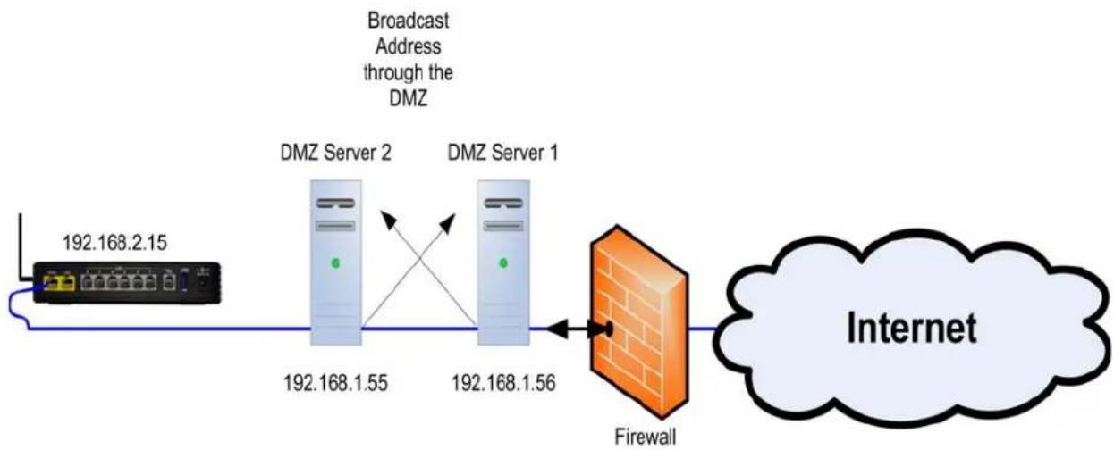
flowchart
graph LR
    A["192.168.2.15"] --> B["DMZ Server 2"]
    B --> C["192.168.1.55"]
    C --> D["DMZ Server 1"]
    D --> E["192.168.1.56"]
    E --> F["Firewall"]
    F --> G["Internet"]
    H["Broadcast Address through the DMZ"] --> B
    H --> D
However, the most common use for the "DMZ" is to systemically place a server or gateway directly onto the Internet without requiring a class "A" or "B" address.
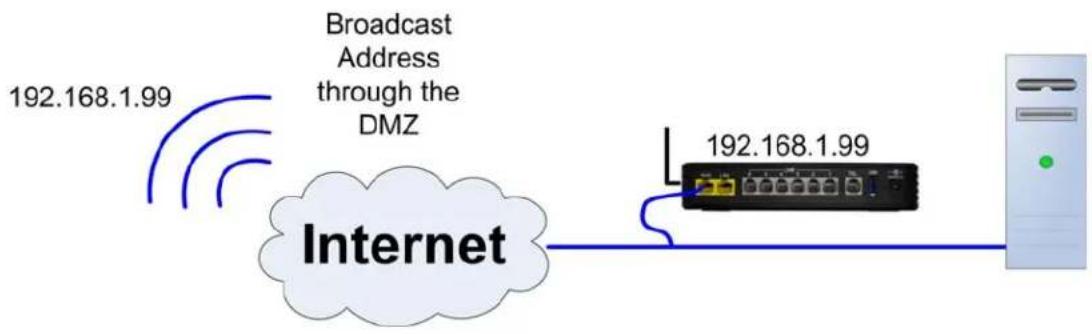
flowchart
graph LR
    A["Internet"] -->|192.168.1.99| B["Broadcast Address through the DMZ"]
    B --> C["IP Address"]
    C --> D["Server"]

text_image
CluePlacing a server or gateway may open the network to malicious network attacks.
Enter the IP Address of the device to be placed into the "DMZ".
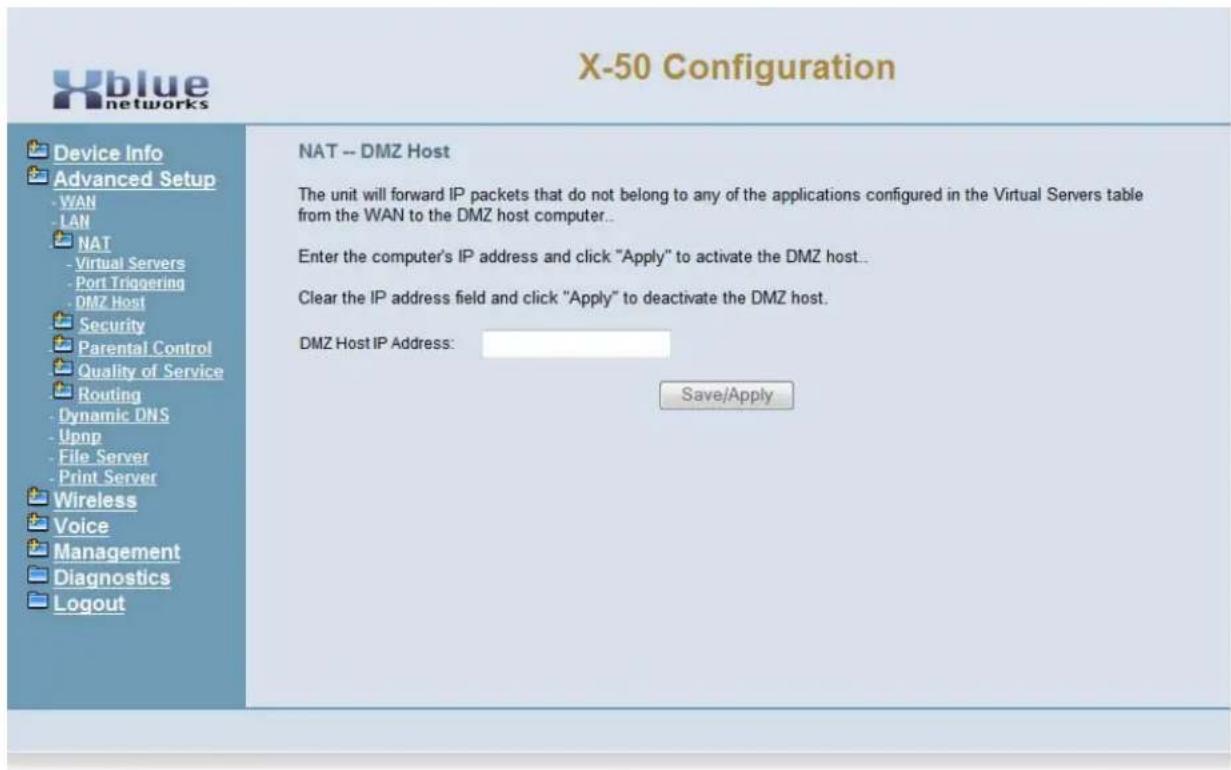
text_image
X-50 Configuration Device Info Advanced Setup WAN LAN NAT Virtual Servers Port Triggering DMZ Host Security Parental Control Quality of Service Routing Dynamic DNS Upnp File Server Print Server Wireless Voice Management Diagnostics Logout NAT -- DMZ Host The unit will forward IP packets that do not belong to any of the applications configured in the Virtual Servers table from the WAN to the DMZ host computer.. Enter the computer's IP address and click "Apply" to activate the DMZ host.. Clear the IP address field and click "Apply" to deactivate the DMZ host. DMZ Host IP Address: Save/ApplySecurity
Security, not to be confused with “Wireless Security” (for wireless security see page 150), is used to block incoming and outgoing IP Addresses as well as a “Parental Control” settings.
- Device Info
- Advanced
- WAN
- LAN
- NAT
- Security
- Outgoing IP Filtering
- Incoming IP Filtering
- Parental Control
• - Quality of Service - Routing
- Dynamic DNS
Incoming and outgoing Filters are used to direct specific packets to the programmed location based on a set of parameters. This type of filtering is commonly used with games to facilitate the movement of IP packets.
Outgoing Filtering
Select Outgoing IP Filtering Setup, and then select "Add" to add IP Address or "Remove" to remove IP Addresses from the current list.
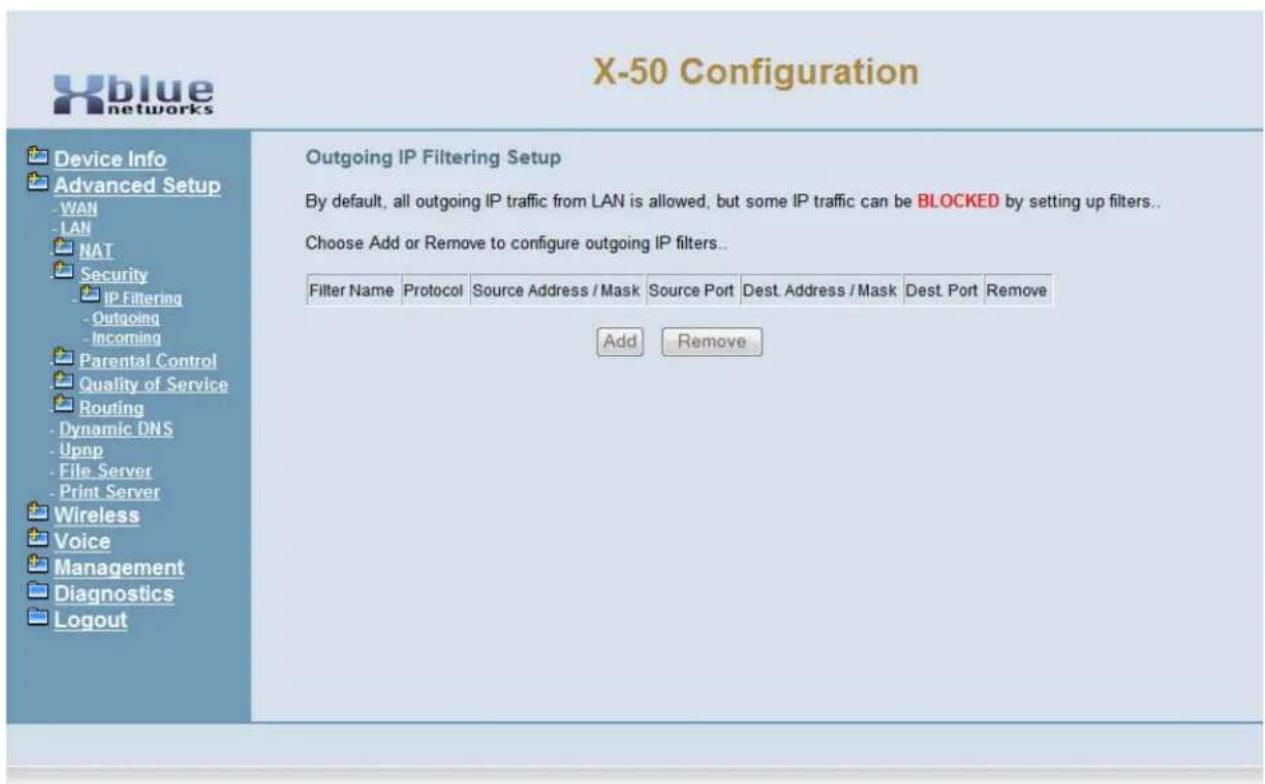
text_image
X-50 Configuration Device Info Advanced Setup -WAN -LAN NAT Security IP Filtering -Outgoing -Incoming Parental Control Quality of Service Routing -Dynamic DNS -Upnp -File Server -Print Server Wireless Voice Management Diagnostics Logout Outgoing IP Filtering Setup By default, all outgoing IP traffic from LAN is allowed, but some IP traffic can be BLOCKED by setting up filters.. Choose Add or Remove to configure outgoing IP filters.. Filter Name Protocol Source Address / Mask Source Port Dest Address / Mask Dest Port Remove Add Remove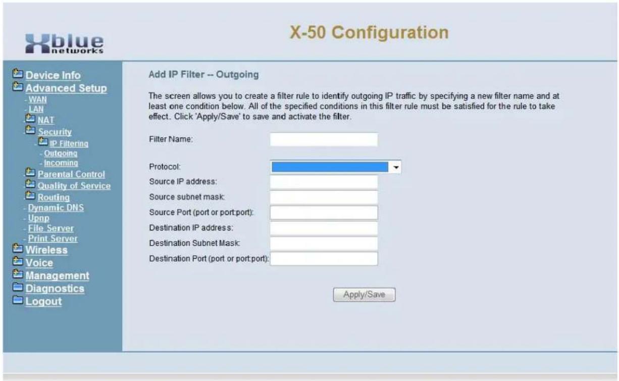
text_image
X-50 Configuration Device Info Advanced Setup WAN LAN NAT Security IP Filtering Outgoing Incoming Parental Control Quality of Service Routing Dynamic DNS Upnp File Server Print Server Wireless Voice Management Diagnostics Logout Add IP Filter -- Outgoing The screen allows you to create a filter rule to identify outgoing IP traffic by specifying a new filter name and at least one condition below. All of the specified conditions in this filter rule must be satisfied for the rule to take effect. Click 'Apply/Save' to save and activate the filter. Filter Name: Protocol: Source IP address: Source subnet mask: Source Port (port or port: port): Destination IP address: Destination Subnet Mask: Destination Port (port or port: port): Apply/SaveThe outgoing IP Filter is a set of parameters used to create a rule, which will block specific IP Addresses. All of the parameters must be true or the packet will continue unchanged.
- Filter Name - Each outgoing filter should have a unique name.
• Source Protocol - TCP, UDP, TCP/UDP or ICMP - Source IP Address - the originating IP Address of packet to be evaluated
- Source Subnet Mask - the originating Subnet Mask of the packet to be evaluated.
- Source Port - the originating port of the packet to be evaluated
- Destination IP Address - the destination IP Address of the packet to be evaluated.
- Destination Subnet Mask - the destination Subnet Mask of the Packet to be evaluated
- Destination Port - the destination port of the packet to be evaluated
Each of these parameters are check, if one of the parameters does not match, the packet is released, otherwise the next parameter will be checked. The action will only take place if all of the parameters are found to be true.
Incoming Filtering
Select Incoming IP Filtering Setup, and then select "Add" to add IP Address or "Remove" to remove IP Addresses from the current list.
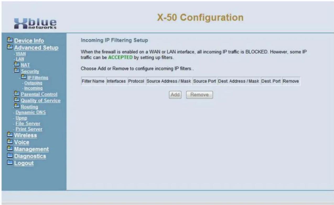
text_image
X-50 Configuration Device Info Advanced Setup - WAN - LAN NAT Security IP Filtering - Outgoing - Incoming Parental Control Quality of Service Routing - Dynamic DNS - Upnp - File Server - Print Server Wireless Voice Management Diagnostics Logout Incoming IP Filtering Setup When the firewall is enabled on a WAN or LAN interface, all incoming IP traffic is BLOCKED. However, some IP traffic can be ACCEPTED by setting up filters. Choose Add or Remove to configure incoming IP filters.. Filter Name Interfaces Protocol Source Address / Mask Source Port Dest. Address / Mask Dest. Port Remove Add Remove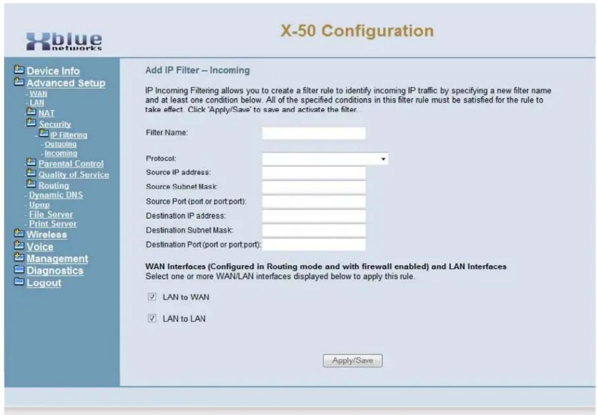
text_image
X-50 Configuration Add IP Filter -- Incoming IP Incoming Filtering allows you to create a filter rule to identify incoming IP traffic by specifying a new filter name and at least one condition below. All of the specified conditions in this filter rule must be satisfied for the rule to take effect. Click 'Apply/Save' to save and activate the filter... Filter Name: Protocol: Source IP address: Source Subnet Mask: Source Port (port or port: port): Destination IP address: Destination Subnet Mask: Destination Port (port or port: port): WAN Interfaces (Configured in Routing mode and with firewall enabled) and LAN Interfaces Select one or more WAN/LAN interfaces displayed below to apply this rule. ✓ LAN to WAN ✓ LAN to LAN Apply/SaveThe incoming IP Filter is a set of parameters used to create a rule, which will allow specific IP Addresses when the Firewall is enabled. All of the parameters must be true or the packet will be blocked.
- Filter Name - Each incoming filter should have a unique name.
• Source Protocol - TCP, UDP, TCP/UDP or ICMP - Source IP Address - the originating IP Address of packet to be evaluated
- Source Subnet Mask - the originating Subnet Mask of the packet to be evaluated.
- Source Port - the originating port of the packet to be evaluated
- Destination IP Address - the destination IP Address of the packet to be evaluated.
- Destination Subnet Mask - the destination Subnet Mask of the Packet to be evaluated
- Destination Port - the destination port of the packet to be evaluated
Each of these parameters are check, if one of the parameters does not match, the packet is released, otherwise the next parameter will be checked. The action will only take place if all of the parameters are found to be true.
Parental Control
Also, known as Administration Control, this feature allows the administrator to identify specific devices to allow or deny access to the Internet. There are two areas of Parental Control, Time Restrictions, which limits the time of day and day of week that a device can access the Internet, and the other allows or denies specific Uniformed Resource Locator (URL) Addresses.
Access Time Restriction
Access Time Restriction
Select Parental Control, and then select "Add" to enter a Time Restriction rule for one a specific client device on the network.
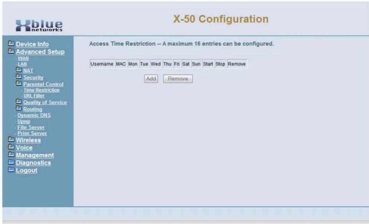
text_image
X-50 Configuration Device Info Advanced Setup - WAN - LAN NAT Security Parental Control - Time Restriction - URL Filter Quality of Service Routing - Dynamic DNS - Upnp - File Server - Print Server Wireless Voice Management Diagnostics Logout Access Time Restriction -- A maximum 16 entries can be configured. Username MAC Mon Tue Wed Thu Fri Sat Sun Start Stop Remove Add Remove
Before beginning to do any restriction programming it is a good idea to gather some information, such as the MAC Addresses of each device to be programmed and all URL's to be allowed or blocked.
Time Restriction
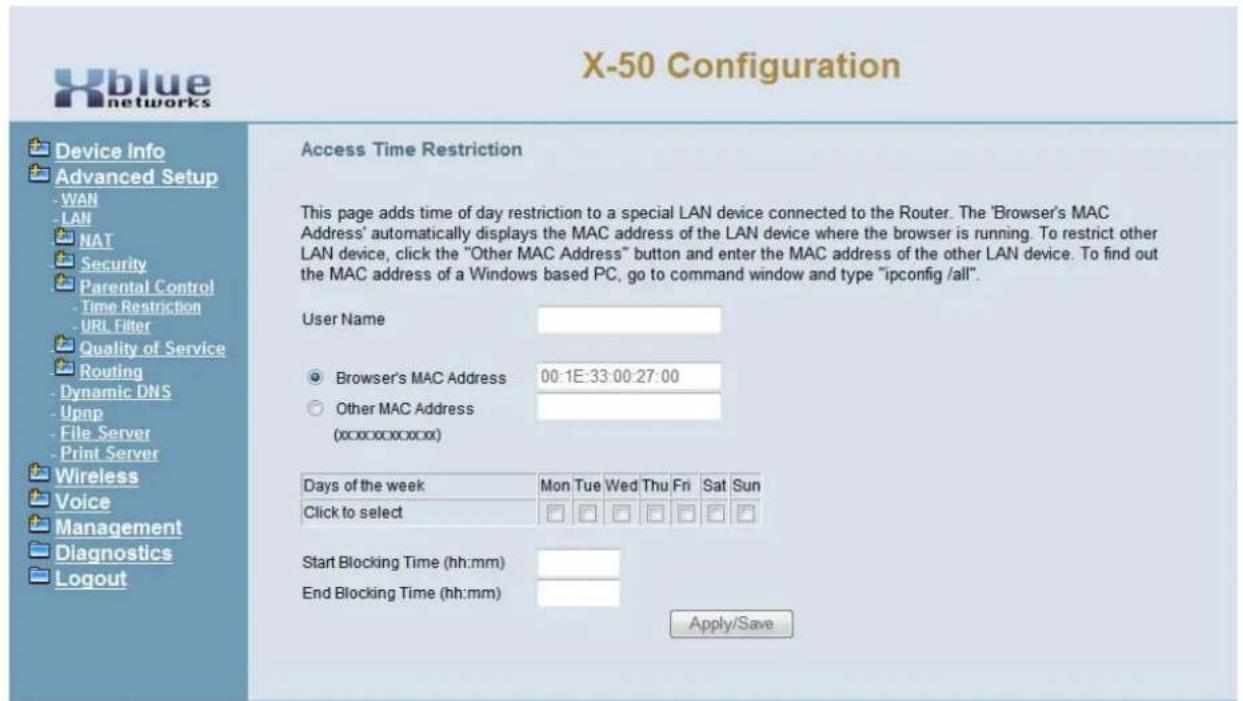
text_image
X-50 Configuration Device Info Advanced Setup -WAN -LAN NAT Security Parental Control -Time Restriction -URL Filter Quality of Service Routing -Dynamic DNS -Upnp -File Server -Print Server Wireless Voice Management Diagnostics Logout Access Time Restriction This page adds time of day restriction to a special LAN device connected to the Router. The 'Browser's MAC Address' automatically displays the MAC address of the LAN device where the browser is running. To restrict other LAN device, click the "Other MAC Address" button and enter the MAC address of the other LAN device. To find out the MAC address of a Windows based PC, go to command window and type "ipconfig /all". User Name Browser's MAC Address 00:1E:33:00:27:00 Other MAC Address (xxxxxxxxxxx) Days of the week Mon Tue Wed Thu Fri Sat Sun Click to select Start Blocking Time (hh:mm) End Blocking Time (hh:mm) Apply/Save- User Name - Enter the user's name or enter a unique name that will identify this control schedule.
- Browser's MAC Address - Enter the physical address of the device that will be using this control schedule.
- Click on "Other MAC Address to enter the MAC Address of the user to be restricted. If programming from that client, just click on "Browser's MAC Address" and it will automatically be entered into the Text Box.
- Days of the Week - Select the days of the week that device will not be able to access the Internet. Not selecting a day, will essentially block the device for that 24 hour period.
- Start and End blocking time - Enter the time to start and end blocking the entered device. The Device will not have access to the Internet during the entered time.
- There can be a maximum of 16 Parental Controls established for each X-50 System.
URL Filter
The URL filter allows the administrator to "exclude" or "include" specific Universal Resource Locator addresses. Unlike the "Time Restriction" entries, which affects only one member, the "URL Filter" affects all devices on the network. This allows the administrator to enter the name of a Website, such as AOL Instant Messaging, rather than the actual IP Address "xxx.xxx.xxx.xxx".
Select Parental Control, URL Filtering and then select "Add" to enter a URL Filtering rule. Select whether to "Exclude" or "Include" entered URL Address
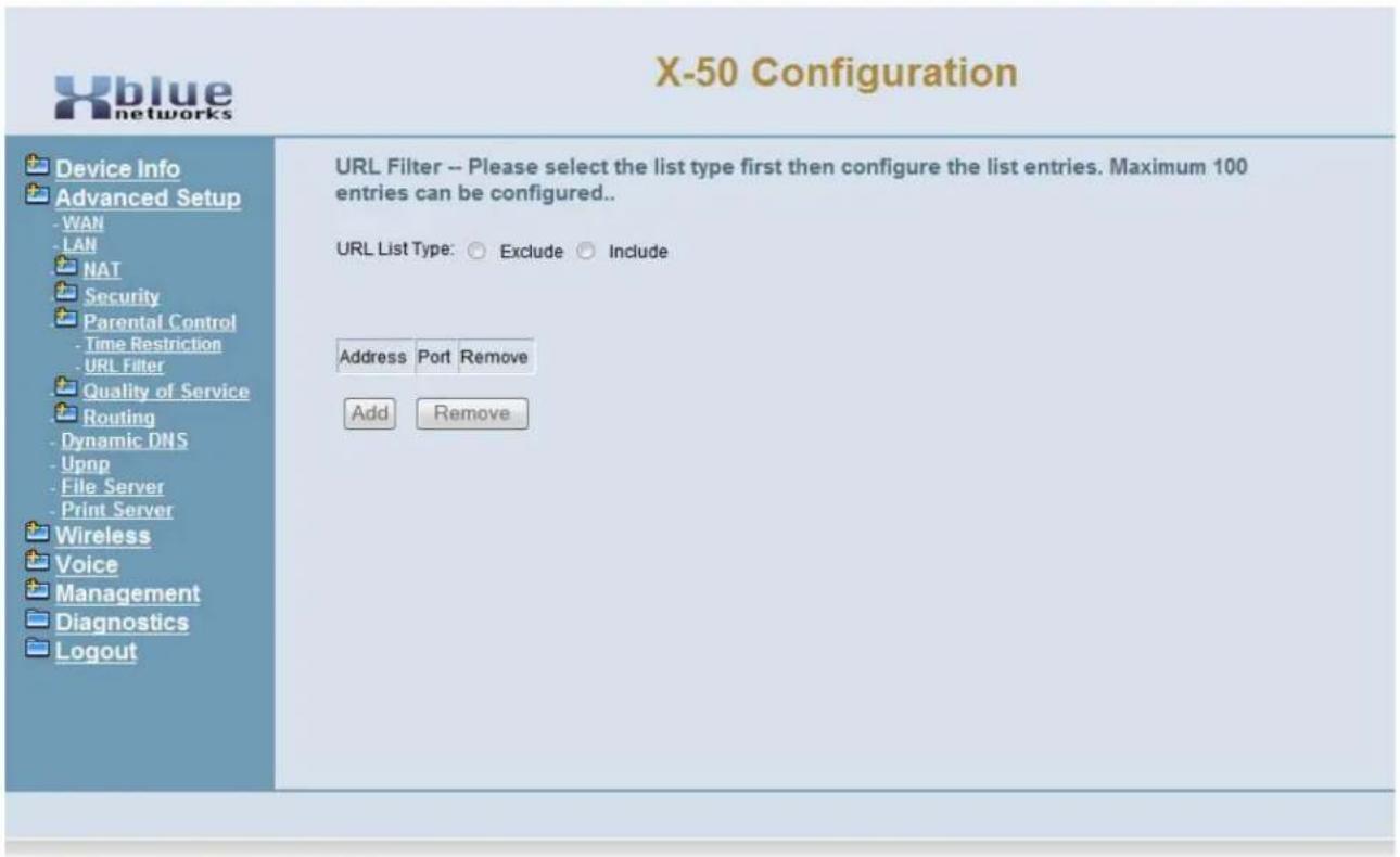
text_image
X-50 Configuration Device Info Advanced Setup - WAN - LAN NAT Security Parental Control - Time Restriction - URL Filter Quality of Service Routing - Dynamic DNS - Upnp - File Server - Print Server Wireless Voice Management Diagnostics Logout URL Filter -- Please select the list type first then configure the list entries. Maximum 100 entries can be configured.. URL List Type: ○ Exclude ○ Include Address Port Remove Add Remove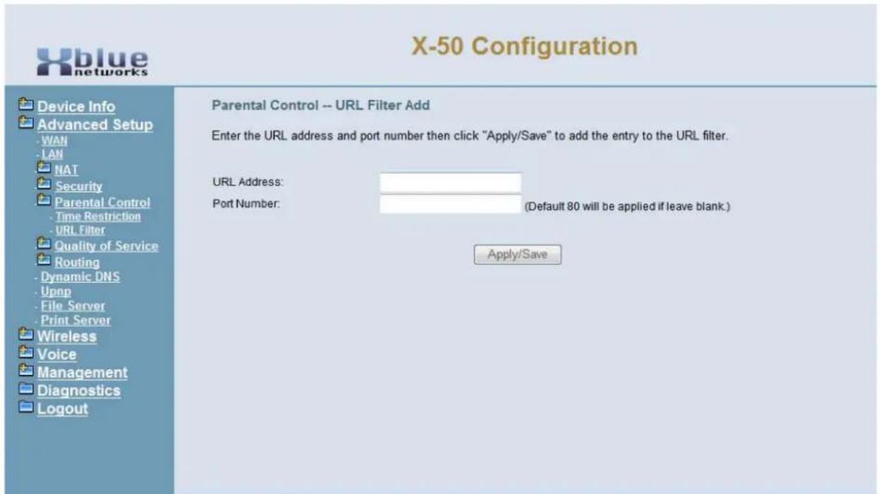
text_image
X-50 Configuration Device Info Advanced Setup -WAN -LAN NAT Security Parental Control -Time Restriction -URL Filter Quality of Service Routing -Dynamic DNS -Upnp -File Server -Print Server Wireless Voice Management Diagnostics Logout Parental Control -- URL Filter Add Enter the URL address and port number then click "Apply/Save" to add the entry to the URL filter. URL Address: Port Number: (Default 80 will be applied if leave blank.) Apply/Save- Enter the URL address to be Included or Excluded
- Enter the Port Number, if different from Port 80, to be Included or Excluded by this entry. The port may be one of the "Well Known Ports" or a specific port such as "AOL Instant Messaging Port 531".
Quality of Service (QoS)
- Device Info
- Advanced
- WAN
- LAN
- NAT
- Security
• - Quality of Service - DSCP Marking
- Bandwidth Control
- Routing
- Dynamic DNS
Quality of Service is a generic term used to represent the ability to prioritize, and if needed change the header for, specific IP packets. QoS is often used to improve voice quality and data transfer rates. However, using QoS does not guarantee voice quality, the only way to guarantee voice quality is to have a data network connection that is large enough to handle both the data and voice traffic. Moreover, the X-50 does not guarantee voice quality. Voice quality is a function of the network, network devices, data integrity and sufficient bandwidth to handle the networks' traffic. Therefore, XBLUE will do its best to help with voice quality but there is no guarantee, written or implied, that the quality of the voice network will be satisfactory, without changing network devices or upgrading available bandwidth.
DSCP (Differentiated Services Code Point)
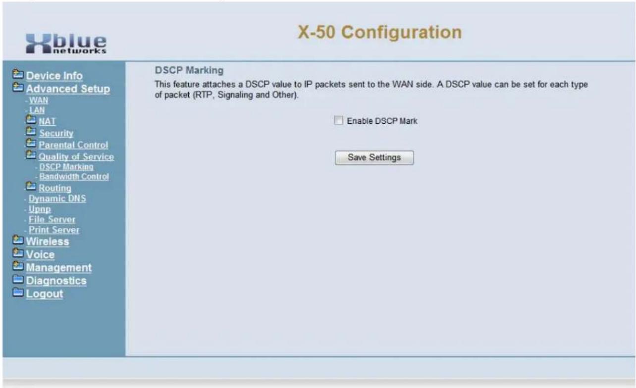
text_image
X-50 Configuration Device Info Advanced Setup - WAN - LAN NAT Security Parental Control Quality of Service - DSCP Marking - Bandwidth Control Routing - Dynamic DNS - Upnp - File Server - Print Server Wireless Voice Management Diagnostics Logout DSCP Marking This feature attaches a DSCP value to IP packets sent to the WAN side. A DSCP value can be set for each type of packet (RTP, Signaling and Other). Enable DSCP Mark Save SettingsOnce enabled, press "Apply/Save" and the following window will open:
Click on "Add" create a new QoS rule.
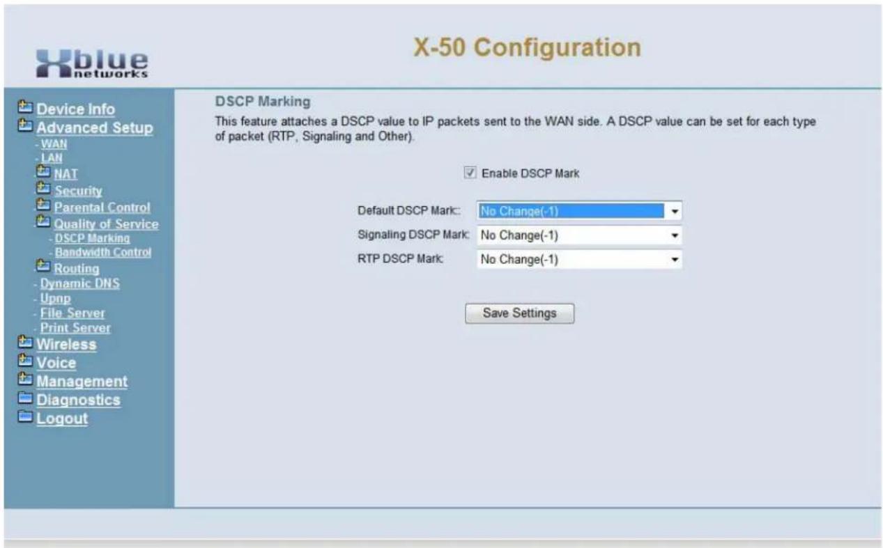
text_image
X-50 Configuration Device Info Advanced Setup - WAN - LAN NAT Security Parental Control Quality of Service - DSCP Marking - Bandwidth Control Routing - Dynamic DNS - Upnp - File Server - Print Server Wireless Voice Management Diagnostics Logout DSCP Marking This feature attaches a DSCP value to IP packets sent to the WAN side. A DSCP value can be set for each type of packet (RTP, Signaling and Other). Enable DSCP Mark Default DSCP Mark: No Change(-1) Signaling DSCP Mark: No Change(-1) RTP DSCP Mark: No Change(-1) Save SettingsDefault DSCP Mark
DSCP - Differentiated Services Code Point - is a 6-bit field in the IP header, used for QoS Classification. If it is set to "No Change" or "Best Effort" then no QoS will take place.
- Default DSCP Mark - Using the drop down menu, select the protocol that will be identified for QOS processing.
- Signaling DSCP Mark - Using the drop down menu, select how the protocol will be modified for processing.
- RTP DSCP Mark - Using the drop down menu, select what order the packets will be processed.
- CS - Class Selector - Prior to the use of Assured Forwarding Classes, Class Selector was used. Class Selector, is not very flexible because it uses the Precedence field in the Type of Service to prioritize packets.
- Expedited Forwarding has the characteristics of low delay, low loss, and low jitter, making it suitable for Voice, Video and other real-time services. To avoid larger delays, it is important not to use Expedited Forwarding for more than 1/3 of the network traffic.
Bandwidth Control
Bandwidth Control is used to ensure that the highest priority IP packets are given priority over all other IP Packets. At default, the system automatically assigns voice packets the highest priority.
Select enable or disable of the Bandwidth Control, and then select "Save".
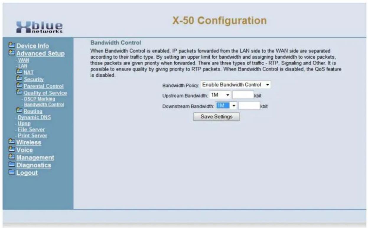
text_image
X-50 Configuration Bandwidth Control When Bandwidth Control is enabled, IP packets forwarded from the LAN side to the WAN side are separated according to their traffic type. By setting an upper limit for bandwidth and assigning bandwidth to voice packets, those packets are given priority when forwarded. There are three types of traffic - RTP, Signaling and Other. It is possible to ensure quality by giving priority to RTP packets. When Bandwidth Control is disabled, the QoS feature is disabled. Bandwidth Policy: Enable Bandwidth Control Upstream Bandwidth: 1M kbit Downstream Bandwidth: 1M kbit Save Settings Device Info Advanced Setup -WAN -LAN NAT Security Parental Control Quality of Service -DSCP Marking -Bandwidth Control Routing -Dynamic DNS -Upnp -File Server -Print Server Wireless Voice Management Diagnostics Logout• Bandwidth Control
• Enabled - Bandwidth control will prioritize IP Packets
- Disabled - IP Packets will not be analyzed or prioritized
- Upstream Bandwidth - This feature is used to determine the size of the upstream information
- Downstream Bandwidth - This feature is used to determine the size of the downstream information
Routing
- Device Info
- Advanced
- LAN
- WAN
- NAT
- Security
• - Quality of Service - Routing
- Static Route
- RIP
- Dynamic DNS
Static Routing
Static routing is used to establish IP Packet routing without requiring the devices to communicate with each other. This is considered a "no fault" network, because there is no way for the network to recover in the event of a failure.
Select Static Route, and then select "Add" to the static routing address, select "save" to active the route.
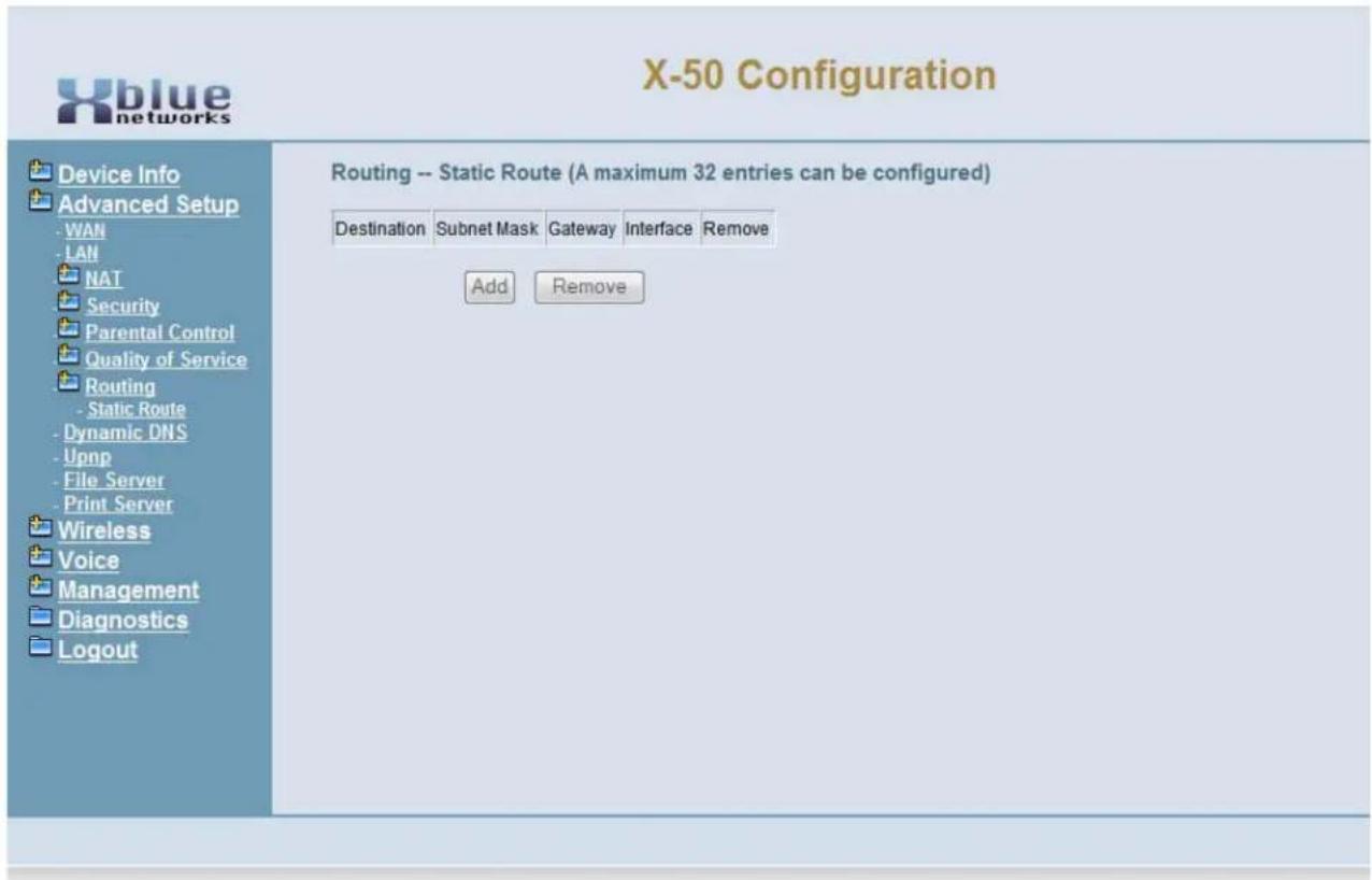
text_image
X-50 Configuration Device Info Advanced Setup WAN LAN NAT Security Parental Control Quality of Service Routing Static Route Dynamic DNS Upnp File Server Print Server Wireless Voice Management Diagnostics Logout Routing -- Static Route (A maximum 32 entries can be configured) Destination Subnet Mask Gateway Interface Remove Add Remove- Enter the Destination Network Address
- Enter the Subnet Mask of the Destination Network Address
- Enter the Gateway IP Address
- Select if the routing will be sent through the WAN/eth0 or the LAN/br0
Select Static Route, and then select "Add" to the static routing address, select "save" to active the route.
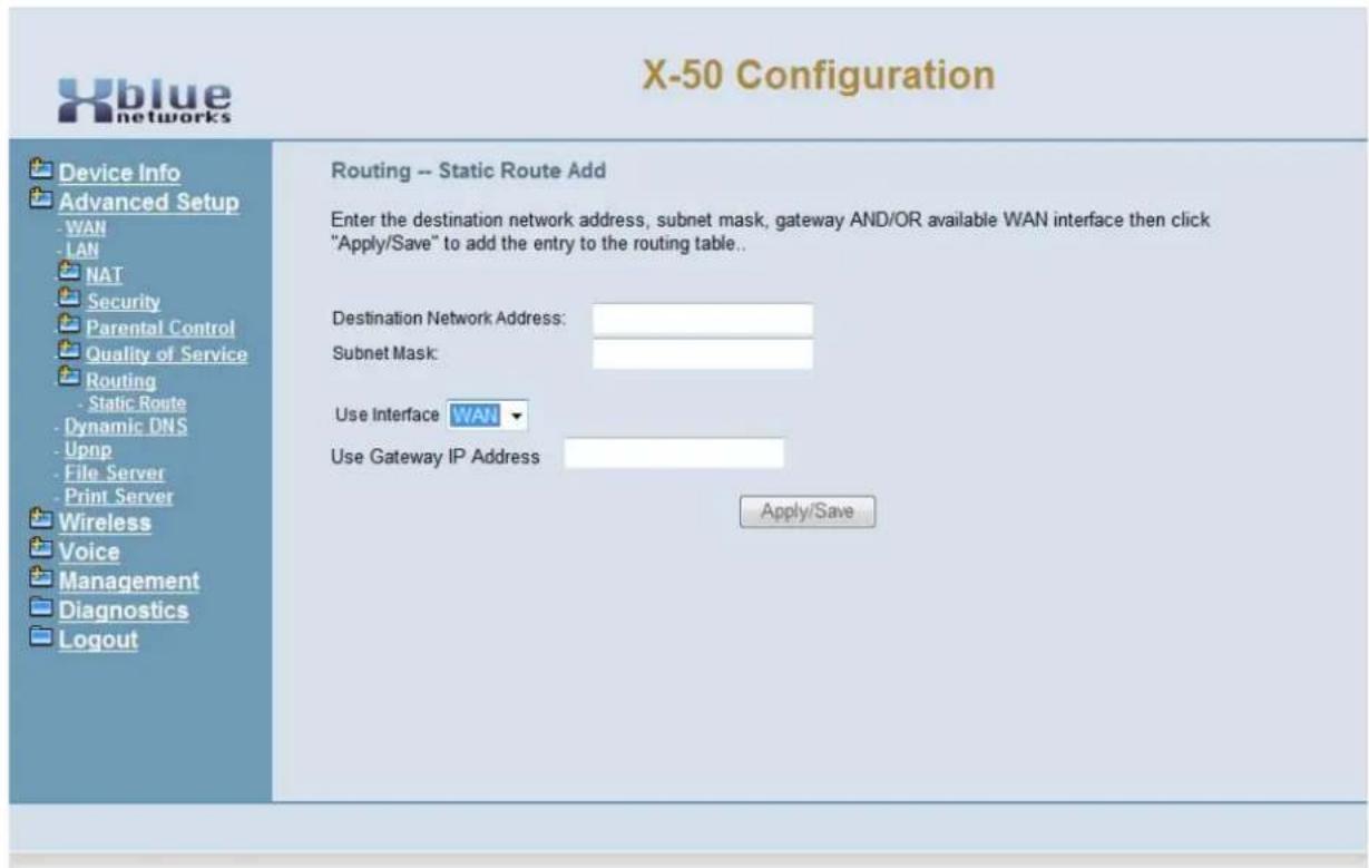
text_image
X-50 Configuration Device Info Advanced Setup -WAN -LAN NAT Security Parental Control Quality of Service Routing - Static Route - Dynamic DNS -Upnp - File Server - Print Server Wireless Voice Management Diagnostics Logout Routing -- Static Route Add Enter the destination network address, subnet mask, gateway AND/OR available WAN interface then click "Apply/Save" to add the entry to the routing table.. Destination Network Address: Subnet Mask: Use Interface WAN Use Gateway IP Address Apply/Save- Destination Network Address - Enter the Destination Network IP Address
- Subnet Mask - Enter the Destination Network Subnet Mask
- Use Interface - Select between WAN and LAN
- Use Gateway/IP Address - Enter the Gateway IP Address
Dynamic DNS
- Device Info
- Advanced
- WAN
- LAN
- NAT
- Security
• - Quality of Service - Routing
- Dynamic DNS
Unlike Standard Domain Name System (DNS), Dynamic DNS (DDNS) does not require a static Class "A" or "B" IP address. However, Dynamic DNS requires the device (server, gateway, router etc.) to run a special software application that continuously identifies the individual unit to the remote DNS Server, allowing the IP address to change without disrupting service.
The X-50 has two Dynamic DNS software applications pre-loaded; DynDNS.org and TZO.
Select Dynamic DNS, and then select "Add" to enable Dynamic DNS. Press "Save" to retain the changes.
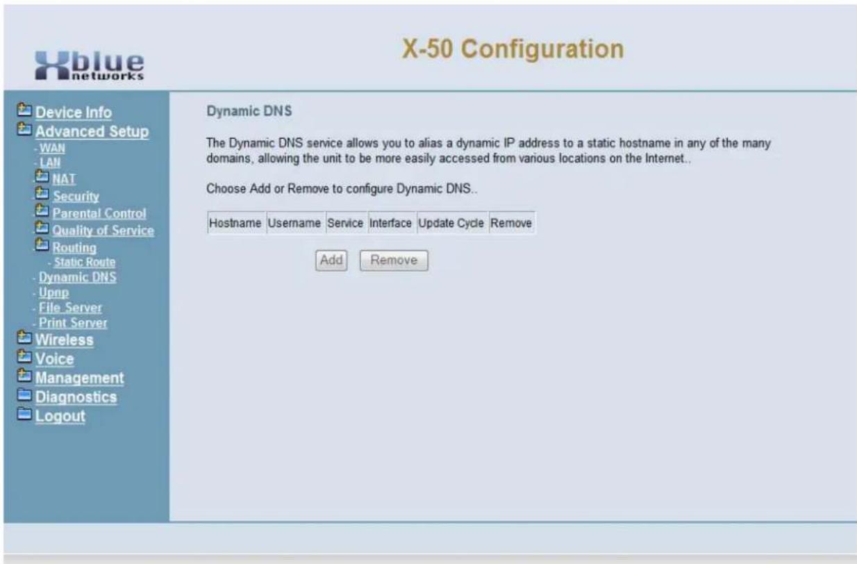
text_image
X-50 Configuration Device Info Advanced Setup - WAN - LAN NAT Security Parental Control Quality of Service Routing - Static Route - Dynamic DNS - Upnp - File Server - Print Server Wireless Voice Management Diagnostics Logout Dynamic DNS The Dynamic DNS service allows you to alias a dynamic IP address to a static hostname in any of the many domains, allowing the unit to be more easily accessed from various locations on the Internet.. Choose Add or Remove to configure Dynamic DNS.. Hostname Username Service Interface Update Cycle Remove Add RemoveSelect Dynamic DNS, and then select "Add" to enable Dynamic DNS. Press "Save" to retain the changes.
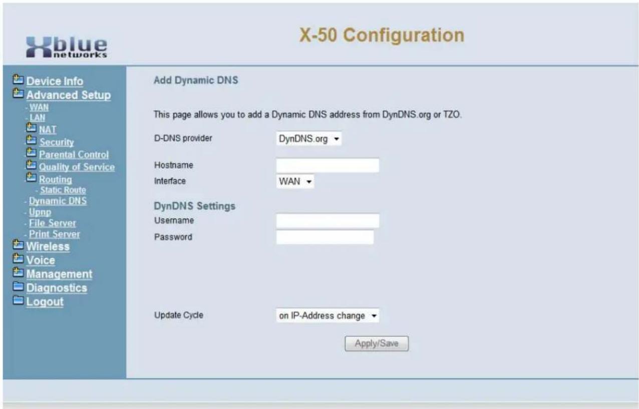
text_image
X-50 Configuration Device Info Advanced Setup - WAN - LAN NAT Security Parental Control Quality of Service Routing - Static Route - Dynamic DNS - Upnp - File Server - Print Server Wireless Voice Management Diagnostics Logout Add Dynamic DNS This page allows you to add a Dynamic DNS address from DynDNS.org or TZO. D-DNS provider DynDNS.org ▼ Hostname Interface WAN ▼ DynDNS Settings Username Password Update Cycle on IP-Address change ▼ Apply/Save- Select the DDNS Provider (DynDNS.org or TSO)
- Enter the name that will be associated to the Dynamic IP Address
- Select Between "WAN/eth0" and "LAN/bro0"
- DynDNS Settings - Enter the User Name and Password associated with the DNS account.
Universal Plug and Play (UPnP)
Universal Plug and Play is a set of protocols created specifically to allow devices on a peer to peer network, generally using either TCP port 5000 or UDP port 1900, to connect seamlessly and simplify their implementation.
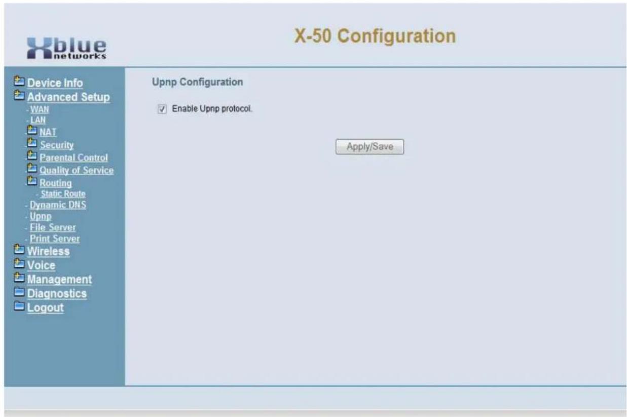
text_image
X-50 Configuration Device Info Advanced Setup - WAN - LAN NAT Security Parental Control Quality of Service Routing - Static Route - Dynamic DNS - Upnp - File Server - Print Server Wireless Voice Management Diagnostics Logout Upnp Configuration Enable Upnp protocol. Apply/SaveFile Server
This future feature will allow the administrator share the contents of an external hard drive by connecting one to the USB port on the X-50 system.

text_image
X-50 Configuration Device Info Advanced Setup -WAN -LAN NAT Security Parental Control Quality of Service Routing -Dynamic DNS -Upnp -File Server -Print Server Wireless Voice Management Diagnostics Logout File Server - Configuration File Server provides file sharing service for various Microsoft Windows clients and can integrate with a Windows Server domain. Your USB mass storage can be accessed by Windows/Linux Network Neighborhood Select the desired values and click "Apply/Save" to configure the Mass Storage options ✓ Enable/Disable Mass Storage se. Service Name: XBLUE.GatewayX50 Workgroup: Workgroup Read only access: ✓ Enable/Disable account management. User Name: user Password: ••••• Apply/Save• Service Name - Enter the name that will be used when on the network to identify the storage area
• Workgroup - Enter the workgroup name. At default, the entered name is workgroup
- Read only access - When checked, anyone connected to the device will only be able to read the information.
- User Name - Enter the name that will be used to authenticate a user and give them access to the device.
- Password - Enter then password that will be used to authenticate a user and give them access to the device.
To locate the workgroup:
- On a computer connected to the network, go to "Start" and locate "Control Panel"
- In Control Panel click on the "System" icon
- Click on the "Computer Name" tab (Windows 7 users will click on "Advanced System Settings") and then locate the "Computer Name" tab.
- The workgroup name can be found in the middle of the "Computer Name" tab, next to "Workgroup:".
Note:
The File Server cannot be connected if Printer Server is connected.
Printer Server
The X-50 system can work as a print server, which allows other members of the workgroup to share the printer connected to the USB port.
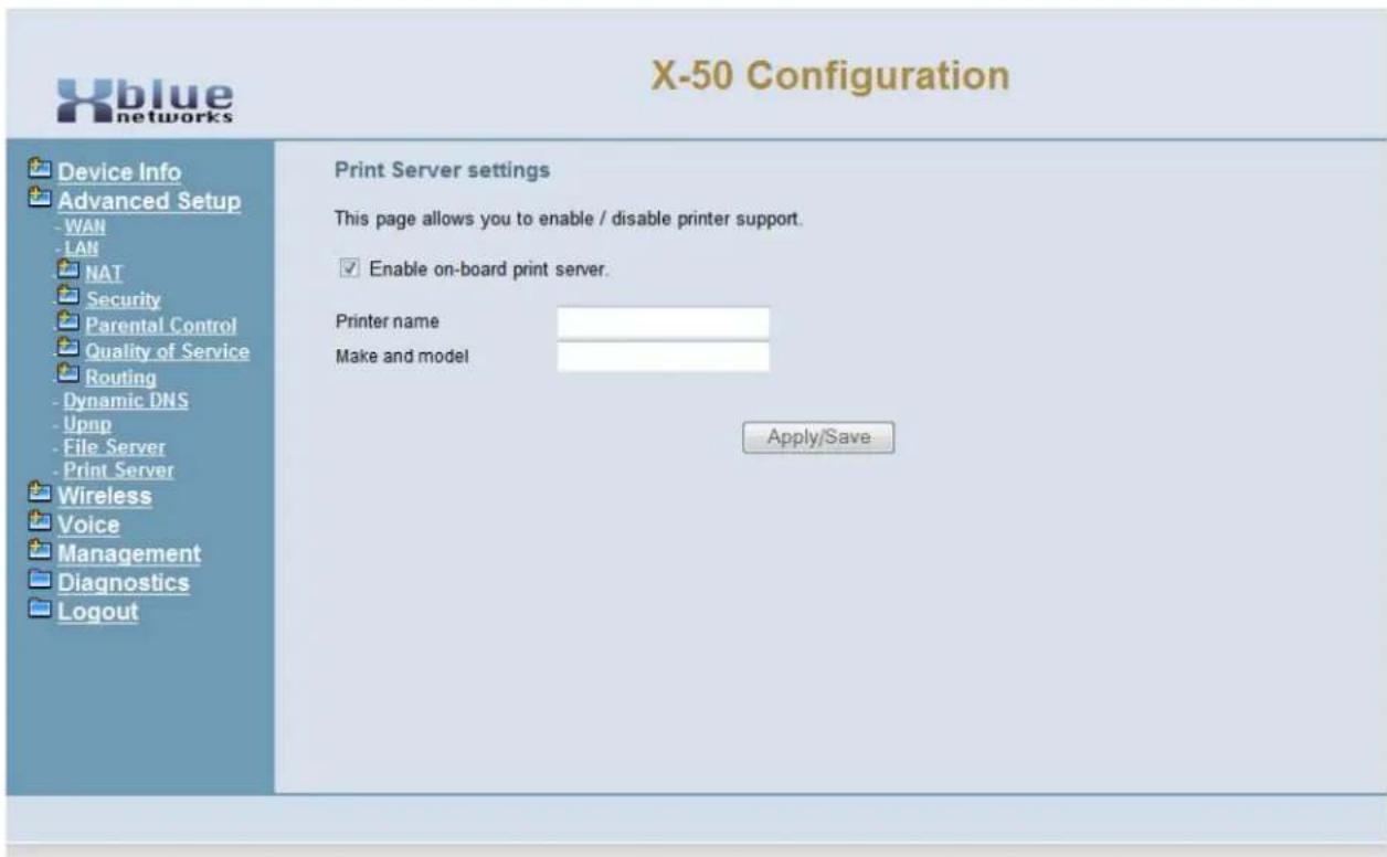
text_image
X-50 Configuration Device Info Advanced Setup - WAN - LAN NAT Security Parental Control Quality of Service Routing - Dynamic DNS - Upnp - File Server - Print Server Wireless Voice Management Diagnostics Logout Print Server settings This page allows you to enable / disable printer support. Enable on-board print server. Printer name Make and model Apply/Save- Enter the name of the printer, such as CanonPrinter, that will be shared in the workgroup
- Enter the make and model number. i.e. Canon iR1024
Use the following steps to add the printer to clients on the network:
- On a computer connected to the network, Click on "Start" and "Printer" (Windows7 - go to "Devices and Printers")
- Click on "Add a Printer"
- Click on "Add a network printer" and then press "Next"
- Click on "Connect to a printer on the Internet or on a home or office network."
- In the URL text window, enter "http://" plus the IP Address, "/printers/" plus the entered "printer name". For example, "http://192.168.10.1/printers/CanonPrinter" and then press next.
- Select the printer manufacturer and then select the specific printer.
- Click on Finish
8 Wireless Programming
Wireless Programming
Integrated in the X-50 is an 802.11a, 802.11b, 802.11g and 802.11n wireless gateway. This gateway can be used by standard computing devices as well as 802.11 communications devices.
At default the wireless interface is enabled, but unsecured. It is very important that security is enabled prior to going on line and although nothing is 100% safe against malicious network attacks, enabling security will minimize the effectiveness of any attacks. In addition, wireless security will stop unintended client devices from joining the network.
- Device Info
- Advanced Setup
- Wireless
- Basic
- Security
- MAC Filter
- Wireless Bridge
- Advanced
-
Station Info
-
Voice
- Management
• Diagnostics - Logout
During the Setup Wizard, some of the default wireless settings may have been changed. Therefore, this manual will show what the defaults are without any changes from the Setup Wizard.
Basic
- Device Info
- Advanced
-
Wireless
-
Basic
- Primary
- Additional
- Security
- MAC Filter
- Wireless Bridge
- Advanced
- Station Info
- Power Saving
Being able to connect to a wireless gateway can be easy and convenient. And Wireless connections are now reaching speeds comparable to a wired connections. However, wireless gateways are easy to locate and join, with or without the administrator's permission, so please enable Wireless Security as soon as possible.
Primary Wireless Network Programming Paramerters
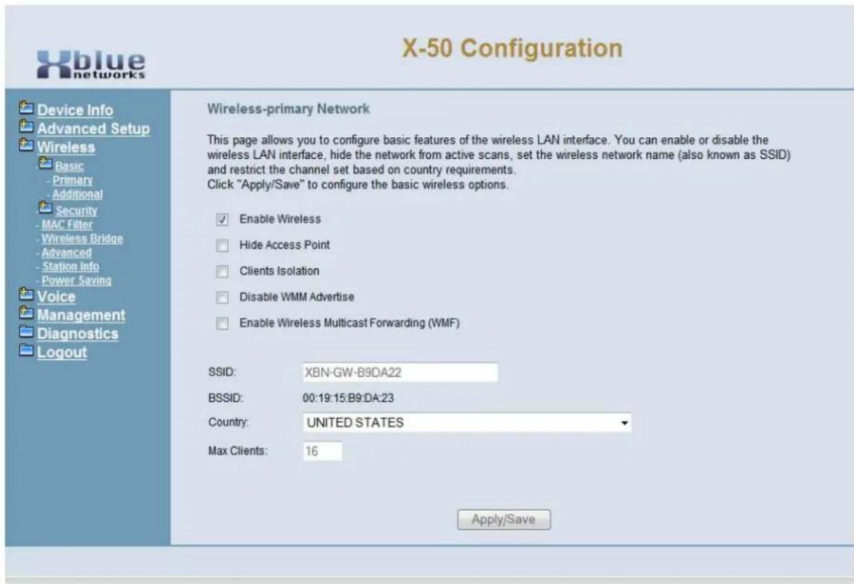
text_image
X-50 Configuration Device Info Advanced Setup Wireless Basic - Primary - Additional Security - MAC Filter - Wireless Bridge - Advanced - Station Info - Power Saving Voice Management Diagnostics Logout Wireless-primary Network This page allows you to configure basic features of the wireless LAN interface. You can enable or disable the wireless LAN interface, hide the network from active scans, set the wireless network name (also known as SSID) and restrict the channel set based on country requirements. Click "Apply/Save" to configure the basic wireless options. ✓ Enable Wireless ☐ Hide Access Point ☐ Clients Isolation ☐ Disable WMM Advertise ☐ Enable Wireless Multicast Forwarding (WMF) SSID: XBN-GW-B9DA22 BSSID: 00:19:15:B9:DA:23 Country: UNITED STATES Max Clients: 16 Apply/Save- Enable Wireless - At default the checkbox indicates that wireless is enabled - when enabled the wireless name (SSID) will be broadcast and visible to anyone that is looking for wireless gateways.
- Hide Access Point - It is possible to enable the wireless but not broadcast the name (SSID). Select the Checkbox to enable "Hide Access Point", i.e. make it invisible or undetectable.
- Clients Isolation - Prevents wireless clients from seeing one another even though they are on the same network. Select the Checkbox to enable "clients isolation", thus isolating the clients from each other.
- Disable WMM Advertise - Wi-Fi Multimedia is used as Quality of Service, controlling the throughput of audio, vidio and voice applications. At default, this is disabled.
- Enable Wireless Multicast Forwarding (WMF) - is a delivery protocol for information to a group of destinations. Although most applications use unicast (broadcasting to a single location), WMF is typically used in oneway streaming media. At default, this is disabled.
-
SSID - Service Set IDentifier is the name that identifies a particular wireless gateway or router. This name is broadcast and easily found by another wireless devices. For security, it is a good idea to change the default SSID name. It is a good idea to use a name that makes sense to the administrator, but not so specific as to give away where the device is located.
-
Do's and Don't's when naming SSID
- Do not use the company name, address, phone number
- Do not use a personal name
- Do not use a birth date or other personal information
- Do not use an antagonistic name such as "BigDog" or "NetworkGenius"
- Do not make the name tantalizing, such as "SEXY-BOX" or "SECRET"
- Do select a name that contains both letters and numbers
- Do select a name that is easy to recognize but not memorize
-
Do consider changing the SSID every few months
-
BSSID - Basic Service Set Identifier is set to the Media Access Control (MAC) address of the X-50 gateway. This is a fixed parameter that cannot be modified.
- Country - Select the country that the X-50 system will be installed. Based on the country select, the X-50 will automatically set the wireless channel.
- Max Clients - Enter the maximum number (valid entries are 1 - 128) of client computers that will be supported by the wireless access point.
- Enable Wireless Guest Network - The Wireless Guess Network allows clients to join the wireless access point (X-50 VoIP Telephone System) without getting access to the network or other network clients. This is similar to a "Hot Spot". Double Click on the Checkbox to enable the "Guest Network"
- Guest SSID - At default the Guest SSID is set to "Guest" but should be changed as indicated in the SSID.
Additional Networks
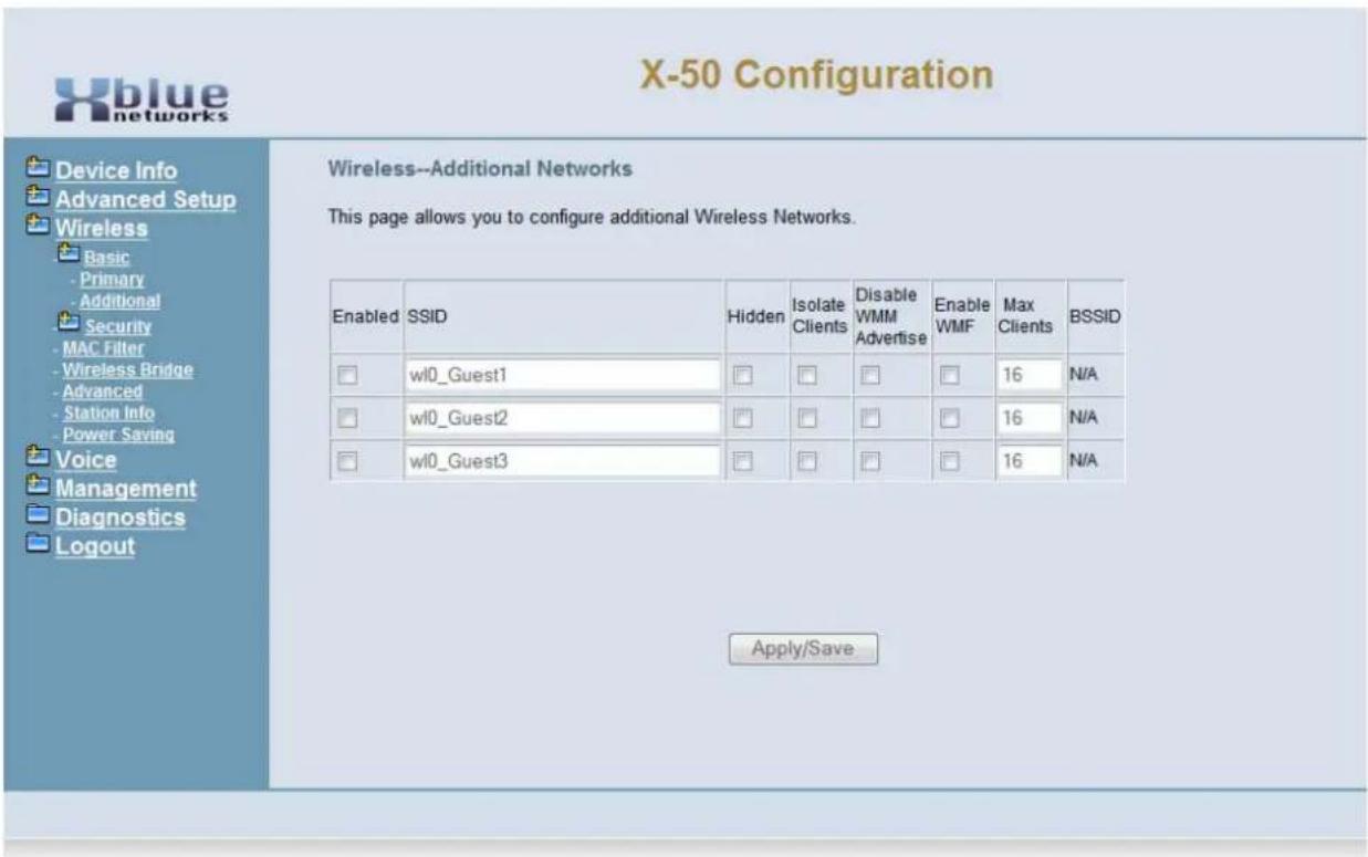
text_image
X-50 Configuration Device Info Advanced Setup Wireless Basic Primary Additional Security MAC Filter Wireless Bridge Advanced Station Info Power Saving Voice Management Diagnostics Logout Wireless--Additional Networks This page allows you to configure additional Wireless Networks. Enabled SSID Hidden Isolate Clients Disable WMM Advertise Enable WMF Max Clients BSSID □ wI0_Guest1 □ □ □ □ 16 N/A □ wI0_Guest2 □ □ □ □ 16 N/A □ wI0_Guest3 □ □ □ □ 16 N/A Apply/Save- Enable Wireless - At default the checkbox indicates that wireless is enabled - when enabled the wireless name (SSID) will be broadcast and visible to anyone that is looking for wireless gateways.
-
SSID - Service Set Identifier is the name that identifies a particular wireless gateway or router. This name is broadcast and easily found by another wireless devices. For security, it is a good idea to change the default SSID name. It is a good idea to use a name that makes sense to the administrator, but not so specific as to give away where the device is located.
-
Do's and Don't's when naming SSID
- Do not use the company name, address, phone number
- Do not use a personal name
- Do not use a birth date or other personal information
- Do not use an antagonistic name such as "BigDog" or "NetworkGenius"
- Do not make the name tantalizing, such as "SEXY-BOX" or "SECRET"
- Do select a name that contains both letters and numbers
- Do select a name that is easy to recognize but not memorize
- Do consider changing the SSID every few months
- Hidden - Hide Access Point - It is possible to enable the wireless but not broadcast the name (SSID). Select the Checkbox to enable "Hide Access Point", i.e. make it invisible or undetectable.
- Isolation Clients - Prevents wireless clients from seeing one another even though they are on the same network. Select the Checkbox to enable “clients isolation”, thus isolating the clients from each other.
- Disable WMM Advertise - Wi-Fi Multimedia is used as Quality of Service, controlling the throughput of audio, vidio and voice applications. At default, this is disabled.
- Enable Wireless Multicast Forwarding (WMF) - is a delivery protocol for information to a group of destinations. Although most applications use unicast (broadcasting to a single location), WMF is typically used in oneway streaming media. At default, this is disabled.
- Maximum Clients - Enter the number of clients that can access the selected wireless access point. a Maximum of 16 clients can be authenticated at one time.
- BSSID - Basic Service Set Identifier is set to the Media Access Control (MAC) address of the X-50 gateway. This is a fixed parameter that cannot be modified.
Security
- Device Info
- Advanced
-
Wireless
-
Basic
- Security
- MAC Filter
- Wireless Bridge
- Advanced
- Station Info
A wireless access point can be very convenient but also very dangerous because it opens the network to unauthorized user access. It cannot be stressed enough how important it is that every wireless access point must have some type of security enabled, even if the system is not broadcasting its SSID.
At default, the X-50 does not have any wireless security enabled.
Note:
If the location is not using the wireless interface, be sure to disable it!

text_image
ClueIt is never a good idea to install a wireless device such as a router or gateway without some sort of encryption and or security. Failure to properly secure a device on a network may result in unauthorized entry into the wireless network. However, even the best encryption does not guarantee unauthorized access, but some encryption is better than no encryption.
The goal of any security is to deny access to unwanted intruders. The X-50 has several different security protocols. Once the security protocol is selected it is very easy to connected authorized clients.
What does that say?

natural_image
Yellow emoji face with confused expression and question marks, no text or symbols presentLike any lock and key system, the key must match the lock in order to gain access. Wireless security is no different. The selected encryption protocol will not allow wireless devices to join the network unless it has the correct key.
Keys are generated several different ways, one simple but effective way is using a shared key which takes a phrase, such as "ItIsWindyInChicago" and put it through a complex mathematical algorithm, which may vary in length from 64 to 128 bits and generates a key that may resemble "Ea1e3683Cd". Any device that broadcasts that key to the X-50 will be granted access otherwise access is denied.
For more advanced network administrators the X-50 comes with 9 different types of security protocols, and it has Wi-Fi Protected Setup (WPS), which is an easy and fast way to establish wireless security.
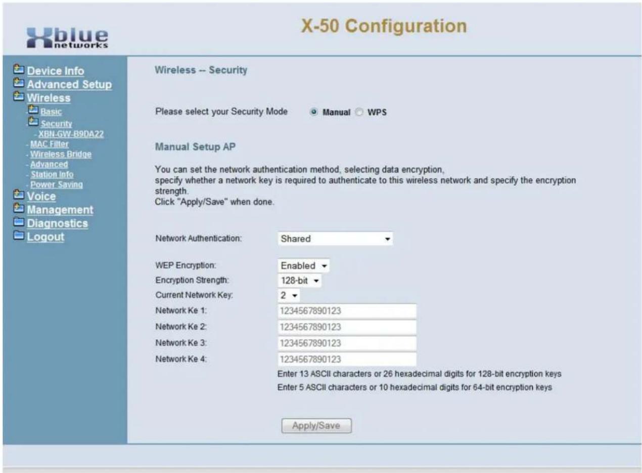
text_image
X-50 Configuration Device Info Advanced Setup Wireless Basic Security -XBN-GW-B9DA22 -MAC Filter -Wireless Bridge -Advanced -Station Info -Power Saving Voice Management Diagnostics Logout Wireless -- Security Please select your Security Mode Manual WPS Manual Setup AP You can set the network authentication method, selecting data encryption, specify whether a network key is required to authenticate to this wireless network and specify the encryption strength. Click "Apply/Save" when done. Network Authentication: Shared WEP Encryption: Enabled Encryption Strength: 128-bit Current Network Key: 2 Network Ke 1: 1234567890123 Network Ke 2: 1234567890123 Network Ke 3: 1234567890123 Network Ke 4: 1234567890123 Enter 13 ASCII characters or 26 hexadecimal digits for 128-bit encryption keys Enter 5 ASCII characters or 10 hexadecimal digits for 64-bit encryption keys Apply/SaveNetwork Authentication - Using the drop down menu select which security protocol will be used
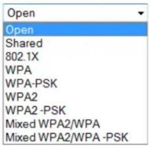
text_image
Open Open Shared 802.1X WPA WPA-PSK WPA2 WPA2 -PSK Mixed WPA2/WPA Mixed WPA2/WPA -PSKAt default, Network Authentication is set to "Open" and WEP encryption is disabled, which allows anyone to join the network. Change WEP Encryption to enabled, and 4 network keys are displayed and become operational.
Open and Shared both use Wired Equivalent Privacy (WEP) encryption which allows the administrator to select between 4 different newtork keys. 802.1x and WPA require the administrator to set valid RADIUS parameters. WPA-PSK requires the administrator to create a valid WPA pre-shared Key. Use the following protocols to establish wireless security.
- Open – no encryption – not recommended without WEP enabled.
- Shared – each device on the wireless network must use the same WEP “Shared” authentication key. This should be considered rudimentary security.
- 802.1x – is a Port based authentication based on Extensible Authentication Protocol, which generally requires a client application, which authenticates to a specified server (RADIUS) before being allowed to connect to the wireless access point.
- WEP – Wired Equivalent Privacy – One of the original wireless encryption protocols, which was thought to be secure. Today, with a minor investment, it can be cracked pretty quickly. This should be considered basic security.
- WPA – Wi-Fi Protected Access – an “intermediate measure” security protocol created by the Wi-Fi Alliance, which uses Tempoal is found to be more secure than WEP.
- TKIP – Temporal Key Integrity Protocol – Was added to WPA and is backwards compatible with older WEP devices, but can be infiltrated with re-injection and spoofing.
- PSK – Pre-Shared Key (RFC 4785) – can be convenient when managing a closed network for easier authentication.
- WPA2 – The second version of WPA, which is more secure, but does not always work with older wireless installations.
- AES – Advanced Encryption Standard – Block Cipher encryption which was adopted by the US Government, and now used world wide for security.
- RADIUS – (RFC 2865) Remote Authentication Dial in User Service – is a client/server protocol using centralized authentication, which requires a network server for all endpoints that connect to the network. This is done in the application layer, using UDP packets.
- RADI US Port – The “Well Known Ports” for sending UDP packets are 1812 and 1645 depending on the network installation and the server.
Select WPS to quickly establish wireless security.
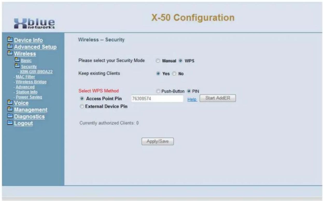
text_image
X-50 Configuration Device Info Advanced Setup Wireless Basic Security -XBN-GW-B9DA22 -MAC Filter -Wireless Bridge -Advanced -Station Info -Power Saving Voice Management Diagnostics Logout Wireless -- Security Please select your Security Mode Manual WPS Keep existing Clients Yes No Select WPS Method Push-Button PIN Access Point Pin 76308574 Help Start AddER External Device Pin Currently authorized Clients: 0 Apply/Save- Keep existing Clients - If there are any authorized clients connected to the wireless access point, they may be automatically granted access, by selecting "Yes". Select "No" to disconnect all current wireless devices.
- Access Point PIN - Personal Identification Number - The X-50 system generates a PIN to be used to authenticate clients on the network.
- External Device PIN - The administrator enters a PIN to be used to authenticate clients on the network.
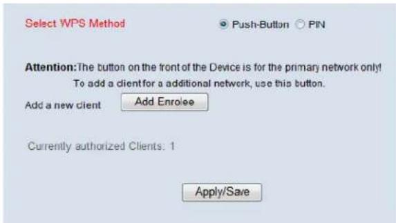
text_image
Select WPS Method Push-Button PIN Attention: The button on the front of the Device is for the primary network only! To add a client for a additional network, use this button. Add a new client Add Enrolee Currently authorized Clients: 1 Apply/Save- Push Button - Select Push button to add clients by pressing "Add Enrolee".
One method of wireless security is "MAC Filtering". This requires the administrator to enter the Media Access Control (MAC) address of each client that has permission to join the wireless access point. If the MAC address is not entered, the client cannot join the network.
MAC Filtering
Select "Wireless MAC Filtering", and then select "Add" to add a MAC address or "Remove" to remove servers from the current list. Click on disable, allow, or deny and then click on add an entry.
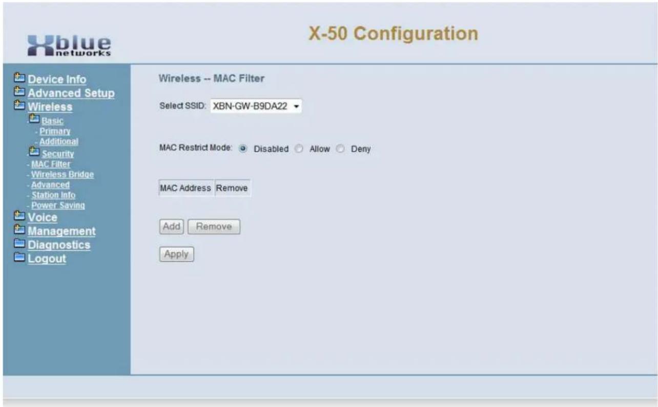
text_image
X-50 Configuration Device Info Advanced Setup Wireless Basic - Primary - Additional Security - MAC Filter - Wireless Bridge - Advanced - Station Info - Power Saving Voice Management Diagnostics Logout Wireless -- MAC Filter Select SSID: XBN-GW-B9DA22 MAC Restrict Mode: Disabled Allow Deny MAC Address Remove Add Remove ApplySelect "Wireless MAC Filtering", and then select "Add" to add a MAC address or "Remove" to remove servers from the current list.
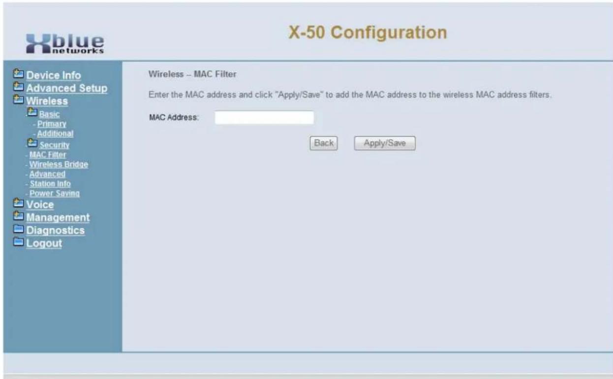
text_image
X-50 Configuration Device Info Advanced Setup Wireless Basic - Primary - Additional Security - MAC Filter - Wireless Bridge - Advanced - Station Info - Power Saving Voice Management Diagnostics Logout Wireless -- MAC Filter Enter the MAC address and click "Apply/Save" to add the MAC address to the wireless MAC address filters. MAC Address: Back Apply/Save
Locating a device's MAC Address:
Usually, the MAC Address can be found on a label, which is affixed to the outside of the device, and labeled "MAC Address" However, some times it is called something different such as physical, hardware or device address, but in all cases the MAC Address is 6 Octets, which is 12 numbers or characters, and should be written as xx:xx:xx:xx:xx:xx. In all cases, a label with the MAC Address must be on the Printed Circuit Board of the device connecting to the network.
A computer's MAC Address is easily found by going to the Command Prompt, "Start --> Accessories --> Run" type CMD, and press enter.
Type [ipconfig /all] and press enter. The MAC Address will probably be written as xx-xx-xx-xx-xx-xx.
- Enter the MAC Address for each client device and press save.
Wireless Bridge
The X-50 can be set as an Access Point or a Wireless Bridge. A wireless access point allows other devices to access the wireless network. Whereas a Wireless Bridge, wirelessly bridges two sections of a network and also allows wired access to both sides of the connection.
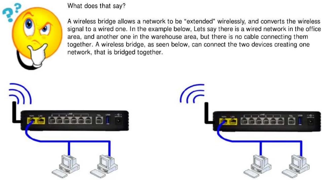
What does that say?
A wireless bridge allows a network to be “extended” wirelessly, and converts the wireless signal to a wired one. In the example below, Lets say there is a wired network in the office area, and another one in the warehouse area, but there is no cable connecting them together. A wireless bridge, as seen below, can connect the two devices creating one network, that is bridged together.
A wireless access point also extension a network, but client computers can only be connected wirelessly.
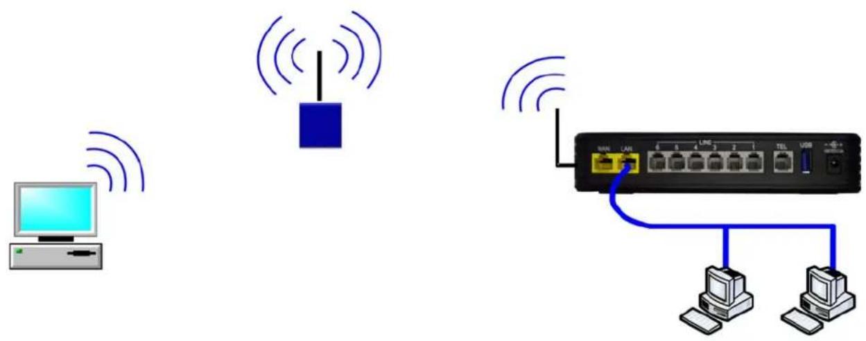
text_image
Diagram showing wireless network connection between a computer, a switch, and a network device with labeled ports and cables.Select between "Wireless Access Point" and "Wireless Bridge", and then select "Enable" and enter the SSID and MAC Address or Enable (Scan) and have the X-50 locate the Wireless Device.
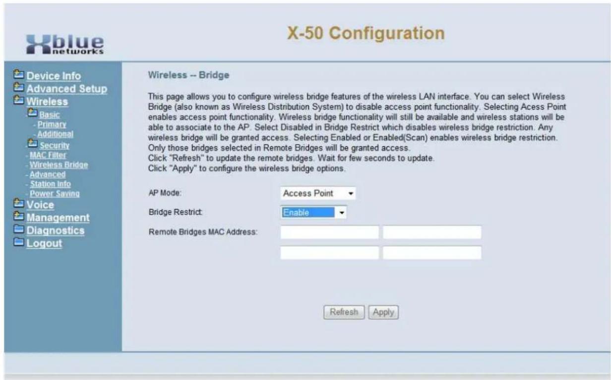
text_image
X-50 Configuration Device Info Advanced Setup Wireless Basic - Primary - Additional Security - MAC Filter - Wireless Bridge - Advanced - Station Info - Power Saving Voice Management Diagnostics Logout Wireless -- Bridge This page allows you to configure wireless bridge features of the wireless LAN interface. You can select Wireless Bridge (also known as Wireless Distribution System) to disable access point functionality. Selecting Acess Point enables access point functionality. Wireless bridge functionality will still be available and wireless stations will be able to associate to the AP. Select Disabled in Bridge Restrict which disables wireless bridge restriction. Any wireless bridge will be granted access. Selecting Enabled or Enabled(Scan) enables wireless bridge restriction. Only those bridges selected in Remote Bridges will be granted access. Click "Refresh" to update the remote bridges. Wait for few seconds to update. Click "Apply" to configure the wireless bridge options. AP Mode: Access Point Bridge Restrict: Enable Remote Bridges MAC Address: Refresh Apply• If disabled, then no action is needed
- Select between Wireless Access Point and Wireless Bridge
- Select enabled and enter the SSID and MAC Address or select Enabled (Scan) to have the X-50 locate the correct wireless device.
Advanced
- Device Info
- Advanced
-
Wireless
-
Basic
- Security
- MAC Filter
- Wireless Bridge
- Advanced
- Station Info
• Power Saving
Several of the advanced wireless parameters are programmed in this area.
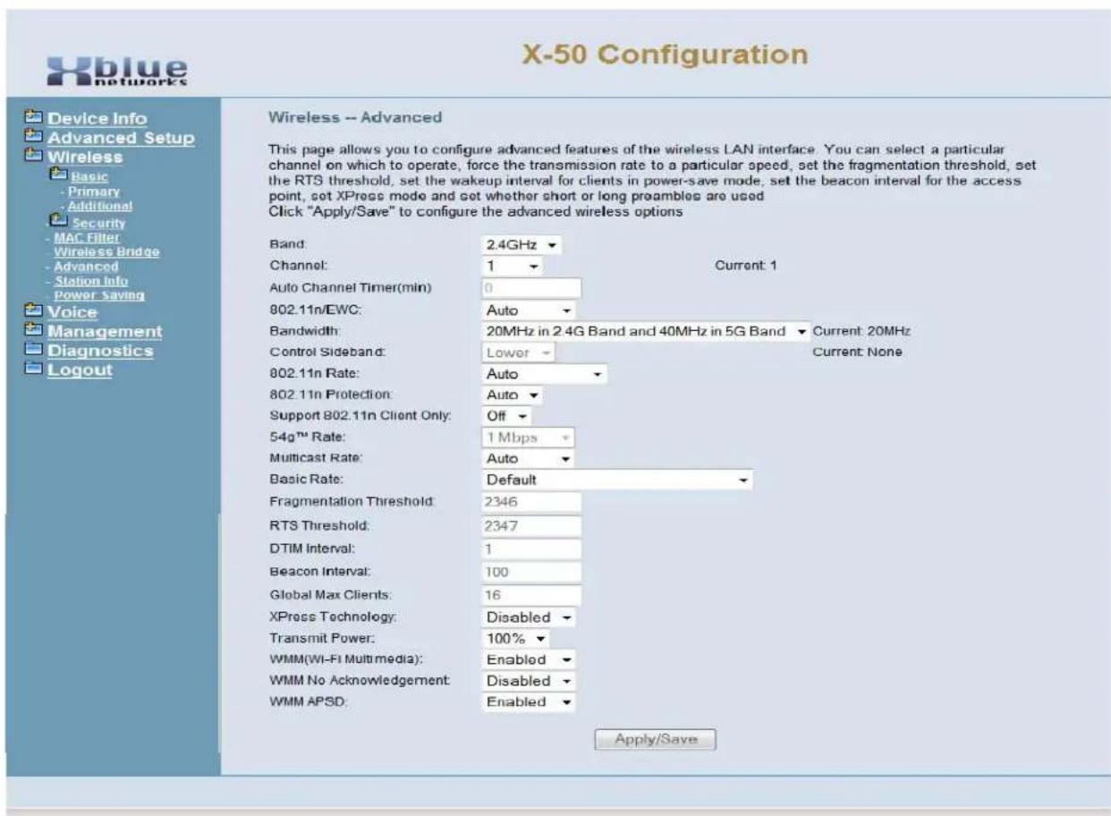
text_image
X-50 Configuration Device Info Advanced Setup Wireless Basic - Primary - Additional Security - MAC Filter - Wireless Bridge - Advanced - Station Info - Power Saving Voice Management Diagnostics Logout Wireless -- Advanced This page allows you to configure advanced features of the wireless LAN interface. You can select a particular channel on which to operate, force the transmission rate to a particular speed, set the fragmentation threshold, set the RTS threshold, set the wakeup interval for clients in power-save mode, set the beacon interval for the access point, set XPress mode and set whether short or long preambles are used Click "Apply/Save" to configure the advanced wireless options Band: 2.4GHz Channel: 1 Current: 1 Auto Channel Timer(min) 0 802.11n/EWC: Auto Bandwidth: 20MHz in 2.4G Band and 40MHz in 5G Band Current: 20MHz Control Sideband: Lower Current: None 802.11n Rate: Auto 802.11n Protection: Auto Support 802.11n Client Only: Off 54g™ Rate: 1 Mbps Multicast Rate: Auto Basic Rate: Default Fragmentation Threshold: 2346 RTS Threshold: 2347 DTIM Interval: 1 Beacon Interval: 100 Global Max Clients: 16 XPress Technology: Disabled Transmit Power: 100% WMM(WI-FI Multimedia): Enabled WMM No Acknowledgement: Disabled WMM APSD: Enabled Apply/Save- Band - 2.4 GHz
- Broadcast band based of the country selection
• Channel default 6 based on the country selection
- Channel is adjustable from "Auto" and 1 - 11
• Automatic Channel Timer (min) - Number of minutes between spectrum scans.
- When "Channel" is set to Auto, the X-50 searches for the best channel in the specified timeframe.
- 802.11n/EWC - This setting automatically uses 802.11n support or disables it.
- Auto or Disable
- Bandwidth - The administrator can select to use both 20 and 40MHz or restrict it to 20MHz in 2.4G band and 40MHz in 5G band.
• 20MHz or 40MHz or 20MHz in 2.4G Band and 40MHz in 5G band
- Control Sideband - If 40MHz is selected - The administrator must select between upper and lower sidband.
- Upper or Lower
- 802.11n Rate - Select a specific data rate or select auto to allow the system to determine the best rate. This is only applicable when 802.11n/EWC is set to auto.
- Auto, use 54g Rate, 6.5, 13, 19.5, 26, 39, 52, 58.5, 65, 78, 104, 117, and 130 Mbps.
- 802.11n protection - used to improve 802.11n performance in a mixed 802.11b and 802.11g protocols. Turn this feature off to maximize throughput, but disables all other protocols.
- Auto or Off
- 802.11n Support Client Only - Select "Off" to allow other wireless devices 801.11b and 802.11g to connect to the system. Select "On" to allow only 802.11n clients to connect to the system.
- Off or On
- 54g ^® Rate - Select the data transfer rate speed from 1 to 54Mbps. Auto, will allow the system to determine the best transfer rate.
• Auto, 1 Mbps through 54 Mbps.
• Multicast Rate - Transmit rate
• Auto (1, 2, 5.5, 11, 12, 18, 24, 36, 54 Mbps)
- Basic Rate - transmit rate - Select the basic rate that a client must support
- Default (All, 1, 2, 5.5, 6, 11, 12, 24 Mbps)
• Fragmentation Threshold 2346
- The X-50 allows the administrator to set the maximum frame size the wireless device can send without fragmenting the frame. This setting is rarely changed. The default setting is the maximum frame size of 2346, which means that it will not fragment any frames that it sends to wireless clients. This setting is best for most environments.
• RTS Threshold 2347
- RTS/CTS frames packet size threshold once exceeded RTS/CTS is sent.
- DTIM Interval - Delivery Traffic Indication Message - Informs the clients about the presence of buffered multicast/broadcast data on the access point.
- The default value is 1 and it can be set from 1 to 255 ms.
- Beacon Interval - Beacon Frames are transmitted to periodically announce the presence of a wireless LAN.
- The default value is 100 and it can be set from 1 to 65535.
- Global Max Clients - This is the maximum number of wireless clients for all established wireless networks.
- XPress® Technology
- Enable this feature to improve wireless performance.
• Transmit Power 100% (20%, 40%, 60%, 80%)
Wireless Programming
- WMM (Wi-Fi Multimedia) - This feature improves the experience for audio, video and voice applications over the Wi-Fi network.
- WMM No Acknowledgement - When disabled, this feature sends wireless confirmaiton packets, however, when disabled it will not send the packets causing less wireless transmission.
- WMM APSD - (Automatic Power Save Delivery) allows SIP telephone endpoints to work in low power consumption mode.
Station Info
- Device Info
- Advanced
-
Wireless
-
Basic
- Security
- MAC Filter
- Wireless Bridge
- Advanced
- Station Info
Station info is a reference only window that shows the authenticated wireless stations and their status. Use this window to ensure that unauthorized wireless devices are not connected to the wireless network.
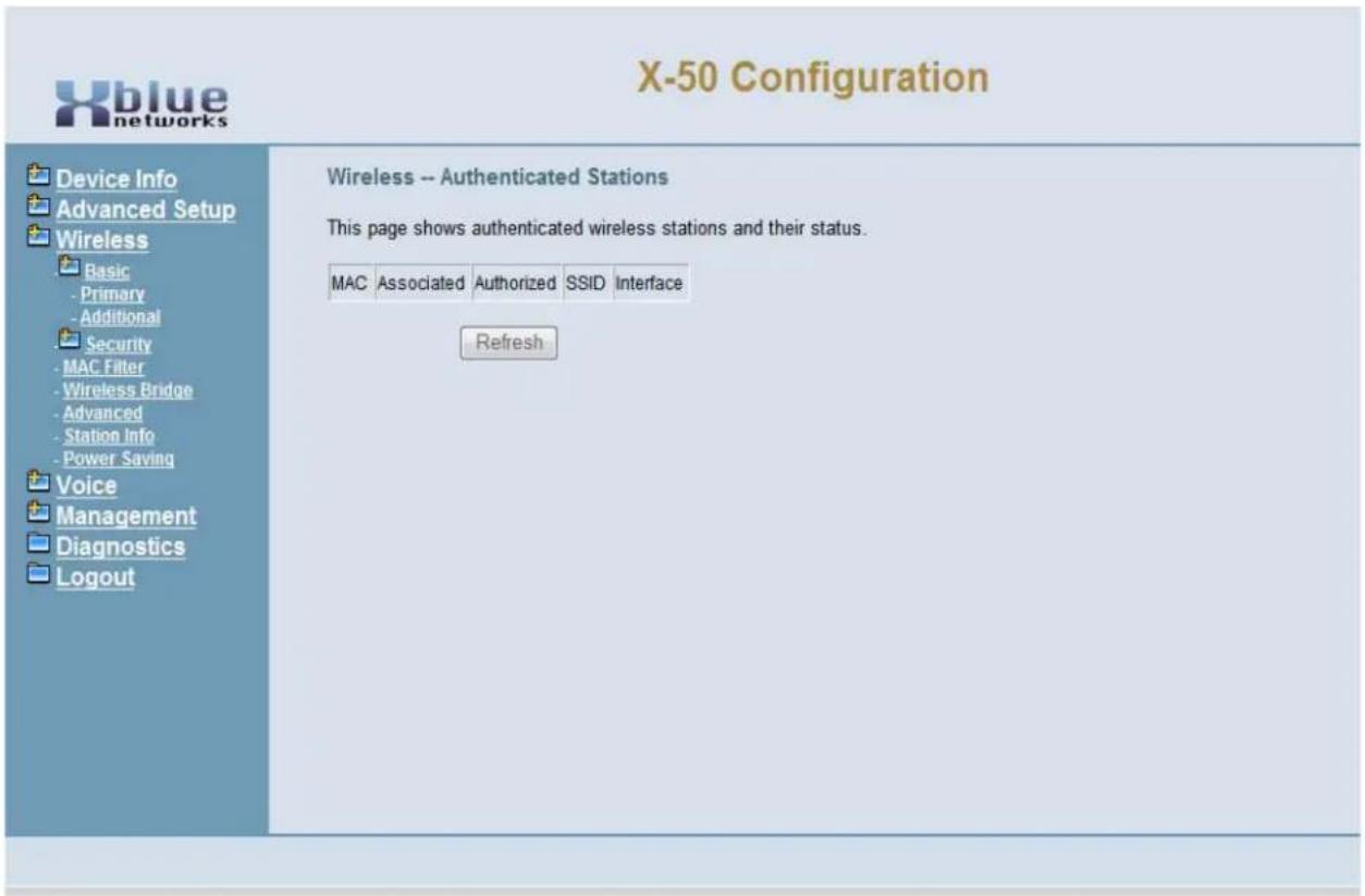
text_image
X-50 Configuration Device Info Advanced Setup Wireless Basic - Primary - Additional Security - MAC Filter - Wireless Bridge - Advanced - Station Info - Power Saving Voice Management Diagnostics Logout Wireless -- Authenticated Stations This page shows authenticated wireless stations and their status. MAC Associated Authorized SSID Interface RefreshIf Unauthorized wireless devices are seen, when reviewing this page, it is a good idea to change the security and reboot the X-50 VoIP Telephone System which will remove the unauthorized devices.
Power Saving
Wireless Power Saving gives the administrator the ability to turn off the WLAN interface at a specific the preprogrammed time. The time must be entered in 24 hour format, where 07:00 is used for 7:00 am and 17:30 is used for 5:30 pm.
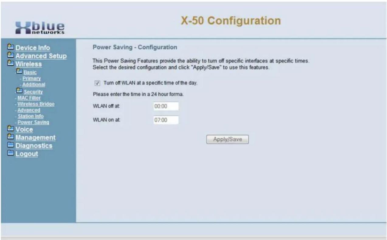
text_image
X-50 Configuration Device Info Advanced Setup Wireless Basic - Primary - Additional Security - MAC Filter - Wireless Bridge - Advanced - Station Info - Power Saving Voice Management Diagnostics Logout Power Saving - Configuration This Power Saving Features provide the ability to turn off specific interfaces at specific times. Select the desired configuration and click "Apply/Save" to use this features. ✓ Turn off WLAN at a specific time of the day. Please enter the time in a 24 hour forma. WLAN off at: 00:00 WLAN on at: 07:00 Apply/SaveXBLUE Wireless Universal Adapter
Because there is not always an Ethernet port where you want to put a telephone, XBLUE suggests an XBLUE Wireless Universal Adapter. Just program the wireless adapter to connect to the X-50, and then connect the adapter to the network port of the X2020. The phone will authenticate to the X-50 just like a wired telephone.
Getting Started
- Make sure that the wireless on the X-50 is on line and operational.
- Connect the Ethernet cable from the Wireless adapter to the X2020 telephone's network connection.
- The integrated wireless adapter will automatically locate the X-50, and authenticate, and download the security password.
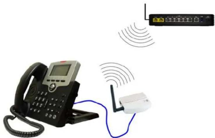
natural_image
Illustration of a classic office telephone with wireless signal and network connections (no text or symbols)Note:
The quality of your wireless connection may affect the quality of the voice connection. There is no guarantee, written or implied, that the XBLUE Wireless adapter will work 100 percent of the time.
Wireless Programming
Notes:
9 Voice
Voice
Use “Voice” area of programming when establishing the system numbering plan, dial codes, service mode, answering position, call routing and restrictions and other telephone system parameters.
- Device Info
- Advanced Setup
- Wireless
- Voice
• + Phone
- + Trunk
• + System
• + Voicemail
- STUN
- Registered Phone
- Management
- Diagnostics
- Logout
Phone Extension
- Device Info
- Advanced Setup
- Wireless
- Voice
• + Phone
- Phone Extension
- Extension Linekey
- + Trunk
• + System
• + Voicemail
- Registered Phone
- STUN
- Management
- Diagnostics
- Logout
During the Setup Wizard, some of the default Voice settings may have been changed. Therefore, this manual will show what the defaults are without any changes from the Initial Setup Wizard.
The system is equipped to support up to 24 SIP telephone extensions and 1 FXS (Single Line or Analog Extension). Depending on the configuration and programming, the SIP Extensions can all be in the same location or spread out throughout the globe.
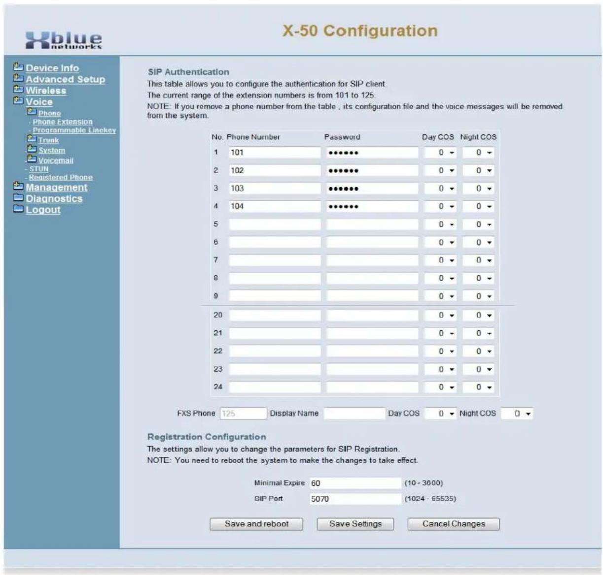
text_image
X-50 Configuration Device Info Advanced Setup Wireless Voice Phone - Phone Extension - Programmable Linekey Trunk System Voicemail - STUN - Registered Phone Management Diagnostics Logout SIP Authentication This table allows you to configure the authentication for SIP client. The current range of the extension numbers is from 101 to 125. NOTE: If you remove a phone number from the table , its configuration file and the voice messages will be removed from the system. No. Phone Number Password Day COS Night COS 1 101 ••••••• 0 ▼ 0 ▼ 2 102 ••••••• 0 ▼ 0 ▼ 3 103 ••••••• 0 ▼ 0 ▼ 4 104 ••••••• 0 ▼ 0 ▼ 5 6 7 8 9 20 21 22 23 24 FXS Phone 125 Display Name Day COS 0 ▼ Night COS 0 ▼ Registration Configuration The settings allow you to change the parameters for SIP Registration. NOTE: You need to reboot the system to make the changes to take effect. Minimal Expire 60 (10 - 3000) SIP Port 5070 (1024 - 65535) Save and reboot Save Settings Cancel ChangesSIP Authentication
The information entered in this window becomes the authentication and extension number, and the password for each SIP extension. In addition, each extension is assigned a day and a night class of service, which controls the extension's dialing privileges. The Extension Number entered here must be within the numbering range as it is defined in the Numbering Plan See page 187.
- Phone Number - Enter the phone number, generally 3 or 4 digits in length, that will be used by a SIP extension to authenticate on the X-50 VoIP Telephone System. This number will also become the extension number for the entered extension. The extension number must be between the extension start and the extension end numbers as defined in the numbering plan page 187.
- Password - Enter a password (up to 24 characters) that will be used to authenticate each SIP extension.
- Day Class of Service - Each extension is assigned a day class of service from 0 through 7 as defined in Call Restriction Table Configuration page found under the Trunk section of the Voice programming parameter.
- Night Class of Service - Each extension is assigned a night class of service from 0 through 7 as defined in Call Restriction Table Configuration page found under the Trunk section of the Voice programming parameter.
- FXS Phone -
- FXS phone is the extension number of the Single Line Telephone Port in the X-50 VoIP Telephone System. Although the extension number cannot be changed here, the extension's name and the day and night classes of service are defined here.
- FXS Display Name - Enter the name to be displayed when this extension calls another extension within the system or voice network.
- FXS Class of Service - Select the Day and Night Class of Service for this extension
- Registration Configuration - Allows the administrator the ability to change some specific SIP registration parameters.
- Minimal Expire - This is the minimal amount of time that an extension will remain registered before trying to reregister.
- SIP Port - This allows the administrator the ability to redefine the port that SIP extensions will use to communicate.
Extension Line Keys

text_image
X-50 Configuration Device Info Advanced Setup Wireless Voice Phone Phone Extension Programmable Linekey Trunk System Voicemail STUN Registered Phone Management Diagnostics Logout Extension Line Keys This page allows you to configure the default settings for extension's line keys. LineKey 1 Type Trunk Value 700 LineKey 2 Type Trunk Value 701 LineKey 3 Type Trunk Value 702 LineKey 4 Type Trunk Value 703 LineKey 5 Type Extension Value 101 LineKey 6 Type Extension Value 102 LineKey 7 Type Extension Value 103 LineKey 23 Type Extension Value 119 LineKey 24 Type Extension Value 120 LineKey 25 Type Extension Value 121 LineKey 26 Type Extension Value 122 LineKey 27 Type Extension Value 123 LineKey 28 Type Extension Value 124 Auto Hold Disable Extension List 101 Configure 102 Configure 103 Configure 104 Configure 105 Configure Save Settings Cancel ChangesThe default programmable line keys on each H2020 telephone can be defined here. Once the SIP telephone extension has been authenticated the default buttons will automatically be assigned to match these entries. However, each extension has the ability to redefine their line keys after they are operational.
Each Programmable Line Key can be a LAN or WAN SIP telephone - showing when it is off-hook or idle - a PSTN or SIP Trunk line - showing when it is busy or idle, Call Park - placing calls onto system (orbit) hold, a Feature key as defined in the Telephone Feature Code Section, a one touch Do Not Disturb (DND) button, a live record button - allowing users to record live conversations on the fly, or it could be programmed as "Others", which allows the administrator to program a virtual extension, UCD group, etc.
Features that can be assigned to a button
None
Extension
Trunk
Call Park
Feature Key
Do Not Disturb
Live Record
Others
- Extension - Enter an extension number that is authenticated on the system to see when it is busy or idle.
- Trunk - Enter the trunk (PSTN or SIP Trunk Line) to see when it is busy or idle.
- Call Park - This will allow the user to press one botton and place calls into Park Orbit.
- Feature Key - Select feature key and enter the feature code to activate a feature shown in the "Telephone Feature".
- Do not Disturb (DND) Select DND to allow the user to place their extension to press one button to place their extension into DND
- Live Record - Select Live Record to allow the user to record a live conversation with the press of a single button.
- Others - Select Others to enter other dial codes such as a UCD group, Page group, etc.
Trunk
- Device Info
- Advanced Setup
- Wireless
- Voice
• + Phone
- + Trunk
- IP Trunk
- Trunk Group
- Answering Position
- Call Routing
- Call Restriction
• - Emergency Numbers
• + System
• + Voicemail
- Registered Phone
- STUN
- Management
- Diagnostics
- Logout
A trunk also known as a Telephone or Central Office (CO) Line, provides access to the Public Switch Telephone Network (PSTN). The X-50 offers two different types of Trunks; POTS and SIP. There are six (6) POTS (Plain Old Telephone Service) Trunks, which are analog lines that are usually connected to a traditional telephone line provider, such as a home telephone line.
There are also eight (8) SIP Trunks, which are telephone lines that are routed over the IP backbone, allowing remote access to the providers Land Telephone (Central Office) Lines. Using SIP trunks will require more bandwidth but may provide features that standard analog lines cannot provide, such as Direct Inward Dial (DID).

What does that say?
Plain Old Telephone Lines are Analog Telephone Trunks (POTS) - Each of these telephone Lines or trunk connects directly from the telephone line provider to the X-50 system.
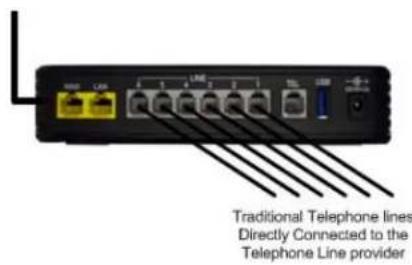
text_image
Traditional Telephone lines Directly Connected to the Telephone Line providerUnlike analog trunks, SIP trunks do not physically connect to the X-50 VoIP Telephone System. Each SIP trunk is assigned a special authentication ID and Password, that systemically connects them from the SIP Telephone Line provider to the X-50 VoIP Telephone System using the broadband (Internet) Connection. Once programmed, the X-50 system and the SIP trunks remain "connected" and are accessed just like an analog trunk.
Because SIP Trunks are accessed through the broadband (Internet) connection it is important that there is enough bandwidth. Contact the ISP to ensure that the bandwidth is a is sufficient to handle the SIP Trunk Requirements. It is suggested that a minimum of 7meg up and 1 meg down, known as 7 x 1, should be enough.
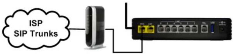
text_image
ISP SIP TrunksSIP Trunks
The X-50 comes equipped to support eight SIP IP Trunks and fifty Direct Inward Dial (DID) numbers. SIP Trunks are not physically connected, they authenticate over the Internet. Thus, the voice quality of these line are directly related to the ISP speed. There are several SIP IP Trunk providers on the market and the integration should be standardized. However, this may not always be the case, and although we do our best to integrate all SIP Trunks, there is no guarantee, written or implied, that every SIP IP Trunk provider will work with the X-50.
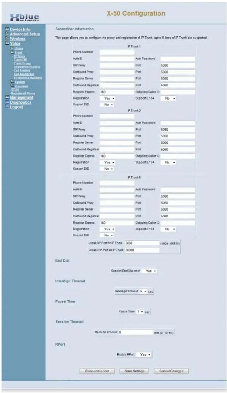
text_image
X-50 Configuration Subscriber Information This page allows you to configure the proxy and registration of IP Trunk, up to 8 lines of IP Trunk are supported. P Trunk 1 Phone Number Auth ID SIP Proxy Outbound Proxy Register Server Outbound Registrar Register Expires 180 Registration Yes ▼ Support E 164 No ▼ Support CIO No ▼ P Trunk 2 Phone Number Auth ID SIP Proxy Outbound Proxy Register Server Outbound Registrar Register Expires 180 Registration Yes ▼ Support E 164 No ▼ Support CIO No ▼ P Trunk 3 Phone Number Auth ID SIP Proxy Outbound Proxy Register Server Outbound Registrar Register Expires 180 Registration Yes ▼ Support E 164 No ▼ Support CIO No ▼ Local SIP Port for IP Trunk: 5060 (1024-65535) Local TCP Port for IP Trunk: 30000 End Dial Support End Dial on # Yes ▼ Interdigit Timeout Interdigit Timeout b sec Pause Time Pause Time t sec Session Timeout Session Timeout: 0 max (0, 10-60) RPort Enable RPort Yes ▼ Save and reboot Save Settings Cancel ChargesThe settings will be provided by the SIP IP Trunk Provider; please contact them to check on any adjustments that may be needed.
- Phone number - The assigned phone number which will be provided by the SIP IP Trunk provider. Generally, this will resemble a standard telephone number, but in some cases there may be a series of numbers plus the actual telephone number.
- Auth ID - Authentication ID - The SIP IP Trunk provider will provide the Authentication ID. Depending on the provider, the Auth ID may be an account number, telephone number or reference number.
- Auth Password - Authentication Password - The SIP IP Trunk provider will provide the Authentication Password. Depending on the provider, the Auth Password may be an account number, telephone number or reference number.

text_image
ClueA Proxy Server is a “go-between” that makes requests on behalf of other clients. Its primary roll is to route packets the fastest way possible and enforce routing policies, even if it has to rewrite specific parts of the request before forwarding the packet.
A Register Server sends a Registrar Server requests so that it will place vital information in a location for the Domain Server. Some SIP IP Trunk providers require that a Registrar Server be reference in order to keep the connection working correctly.
An Outbound Proxy is often used as a central location for security verification before connecting two devices. This is commonly used as an additional layer of security.
- SIP Proxy - The SIP IP Trunk Provider will provide the SIP Proxy. The SIP Proxy can be either a class A or B IP Address, or must likely will be a specific Uniform (Universal) Resource Locator (URL) Address.
- SIP Proxy Port - 5060 is one of the “Well Known Ports” that is used for the transmission of both TCP or UDP SIP Packets. Some providers may require this to be changed, but most will not.
- Outbound Proxy - The SIP IP Trunk Provider will provide the Outbound Proxy. The Outbound Proxy's Address can be either a class A or B IP Address, or must likely will be a specific Uniform (Universal) Resource Locator (URL) Address.
- Outbound Proxy Port - 5060 is one of the “Well Known Ports” that is used for the transmission of both TCP or UDP SIP Packets. Some providers may require this to be changed, but most will not.
- Register Server - The SIP IP Trunk Provider will provide the Registrar Server. The Registrar Server's address can be either a class A or B IP Address, or must likely will be a specific Uniform (Universal) Resource Locator (URL) Address.
- Register Proxy Port - 5060 is one of the "Well Known Ports" that is used for the transmission of both TCP or UDP SIP Packets. Some providers may require this to be changed, but most will not.
- Register Expires - If "Register Status" is set to "On" this timer will be referenced and it is how often the X-50 will send a signal to the Registrar Server in order to keep the information current. If there is no reply within the programmed time, at default 60 seconds, the connection is terminated.
- Outgoing Caller ID - This is the caller ID that will be sent when making an outbound call on the programmed SIP trunk.
-
Registration - If set to no, the IP trunk will not send register to the register proxy.
-
Register Status - When Set to "On" the Register Expires will be referenced, otherwise it will not be referenced. The SIP IP Trunk provider will provide the proper settings for this parameter.
- Support E.164 - This protocol was defined by ITU-T, to standardize international telecommunications numbering plan, used over the Public Switched Telephone Network (PSTN). For proper dialing formats, some SIP IP Trunk Providers may require this to be enabled. At default, it is disabled.
- Support Direct Inward Dial (DID) - When set to "Yes" the IP Trunk can be used in DID operation. See Direct Inward Dial on page 176
Local Port
- Local SIP Port for IP Trunk - Enter the port supplied by the SIP trunk provider.
- Local RTP Port for IP Trunk - Enter the Real-Time Protocol supplied by the SIP trunk provider.
- Support End Dial on # - When set to "Yes" the call will be sent out immediately after pressing the # key.
- Interdigit Timeout - At the expiration of this timer the call will be sent, even if the user is not done dialing.
- Pause Time - This is the amount of time that will be placed into a dialed number when a "P" is entered into the number.
- Session Timeout - This is the amount of communications time for the IP trunk. An entry of Zero means that there is no restriction.
- RPort - When enabled, the client is behind Network Address Translation (NAT), the Rport will allow SIP proxy to append the public IP address the NAT port, and transer the SIP message to the correct location.
Direct Inward Dial
One feature that some SIP Trunk providers offer is the ability to use Direct Inward Dial (DID) numbers. DID numbers are published direct telephone numbers that rings to a specific user's extension, bypassing the attendant and auto attendant. DID's were once saved for large companies who could buy hundreds of sequential telephone numbers, which were assigned to specific employees. SIP Trunk providers allow smaller companies to purchase a limited set of these numbers, such as ten DID's, 2200 to 2210. However, not all SIP trunk providers offer the DID feature so it is important to check before signing any contacts. SIP Trunks with DID assignments are not affected by the Answer Position (See page 179) assignments.
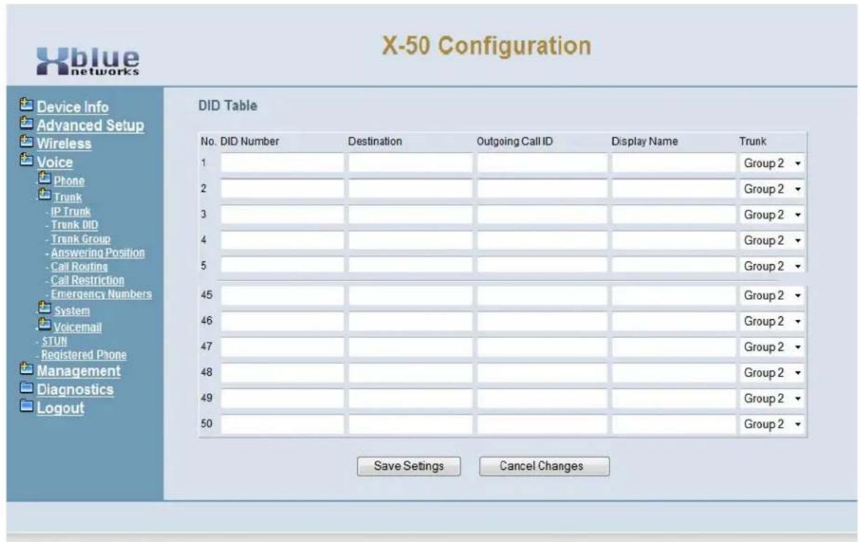
text_image
X-50 Configuration Device Info Advanced Setup Wireless Voice Phone Trunk IP Trunk Trunk DID Trenk Group Answering Position Call Routing Call Restriction Emergency Numbers System Voicemail STUN Registered Phone Management Diagnostics Logout DID Table No. DID Number Destination Outgoing Call ID Display Name Trunk 1 Group 2 2 Group 2 3 Group 2 4 Group 2 5 Group 2 45 Group 2 46 Group 2 47 Group 2 48 Group 2 49 Group 2 50 Group 2 Save Settings Cancel ChangesThe function of this table is to enter the incoming 10 digit telephone number and assign it to a specific telephone extension.
- DID Number - This is the published, direct telephone number that will be dialed to reach the user.
- Destination - also known as the Extension Number - This is the extension number that will ring when the DID number is received into the system.
- Outgoing Call ID - This is the telephone that will be sent by the SIP provider when making a call from the programmed destination.
- Display Name - This is the name that will be displayed when the DID Trunk rings the Extension.
- Trunk - Group - Use the dropdown menu when assigning a DID Trunk to a Trunk Group. The SIP Trunk must be marked as "DID Yes".
Trunk Groups
The X-50 VoIP Telephone System has four (4) Trunk Groups, each that support one or more trunks. Trunk Groups are used to group trunks that are used in similar ways, such as local and long distance trunks. At default, all of the "PSTN" Trunks are in group 1, and SIP Trunks are in group 2.
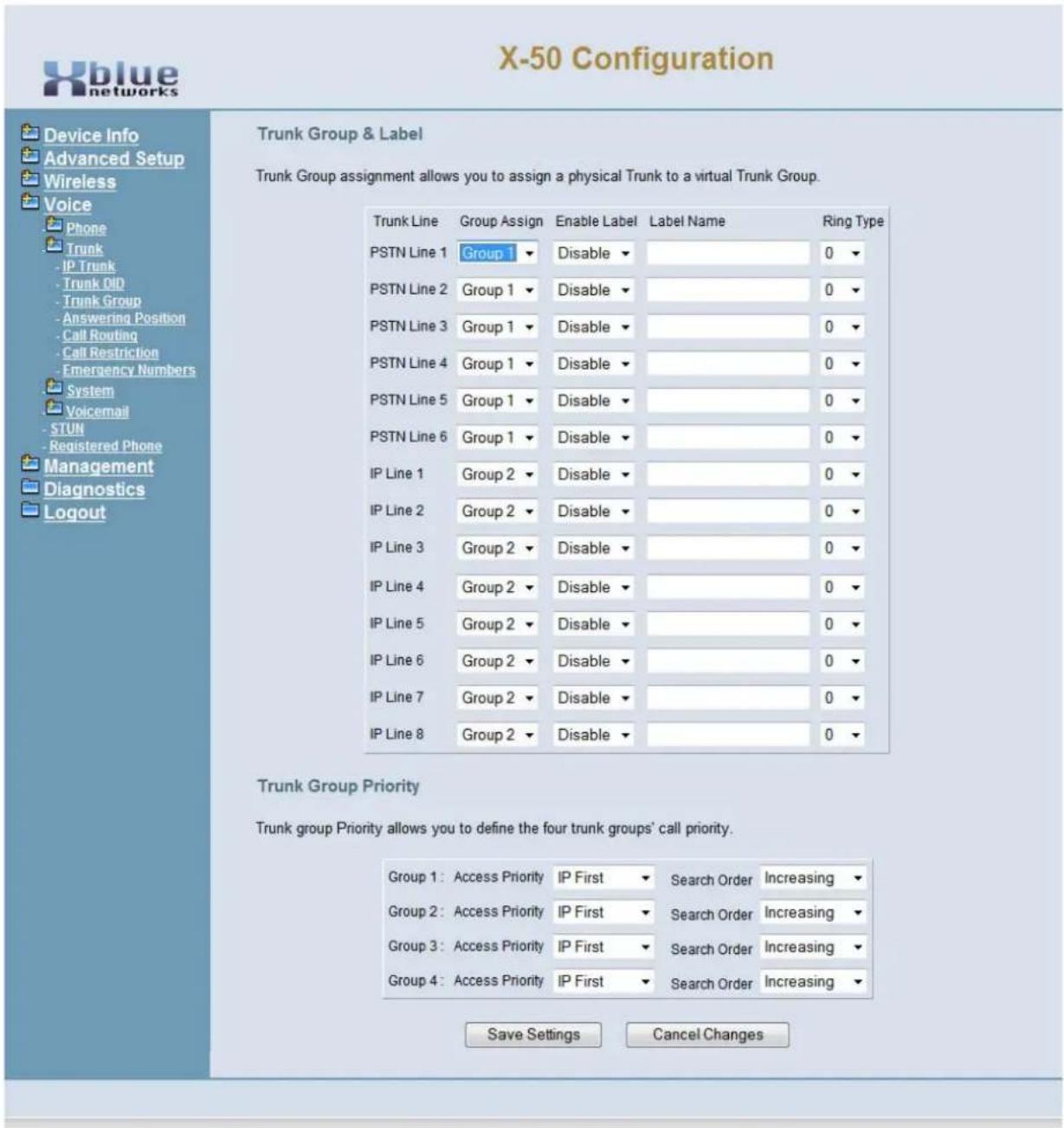
text_image
X-50 Configuration Trunk Group & Label Trunk Group assignment allows you to assign a physical Trunk to a virtual Trunk Group. Trunk Line Group Assign Enable Label Label Name Ring Type PSTN Line 1 Group 1 Disable 0 PSTN Line 2 Group 1 Disable 0 PSTN Line 3 Group 1 Disable 0 PSTN Line 4 Group 1 Disable 0 PSTN Line 5 Group 1 Disable 0 PSTN Line 6 Group 1 Disable 0 IP Line 1 Group 2 Disable 0 IP Line 2 Group 2 Disable 0 IP Line 3 Group 2 Disable 0 IP Line 4 Group 2 Disable 0 IP Line 5 Group 2 Disable 0 IP Line 6 Group 2 Disable 0 IP Line 7 Group 2 Disable 0 IP Line 8 Group 2 Disable 0 Trunk Group Priority Trunk group priority allows you to define the four trunk groups' call priority. Group 1: Access Priority IP First Search Order Increasing Group 2: Access Priority IP First Search Order Increasing Group 3: Access Priority IP First Search Order Increasing Group 4: Access Priority IP First Search Order Increasing Save Settings Cancel ChangesVoice
- Group Assign - Each trunk is a member of one of the four (4) trunk groups, which are grouped in terms of dialing or calling privilege, such as Local and long distance lines.
- Enable Label - Each trunk can be assigned a "Label Name", which is either displayed (Enabled) or not displayed (disabled). At default, all Label Name is disabled.
- Label Name - Each trunk within the group can be labeled, if enabled, when accessed.
- Ring Type - Each group can select one of 10 different ring types.
text_image
0 1 2 3 4 5 6 7 8 9 10Trunk Group Priority
This features allows the administrator to select the order that trunks will be access when making an outbound call.
- Access Priority - Select which type of trunk to be access first when making a call - IP Trunk first or PSTN first
- Search Order - Select which order, highest to lowest (decreasing) or lowest to highest (Increasing) the trunks will be accessed.
Answer Position
Answer position, also know as ring assignment, is where each trunk (PSTN and SIP) are programmed to ring during the Day and Night. The answer position can be set to an Extension, Auto Attendant, Operator or UCD Group. At default, all trunks are set to ring UCD group 430 (see Numbering Plan page 187) during the day, which rings all authenticated extensions and Auto Attendant at night.
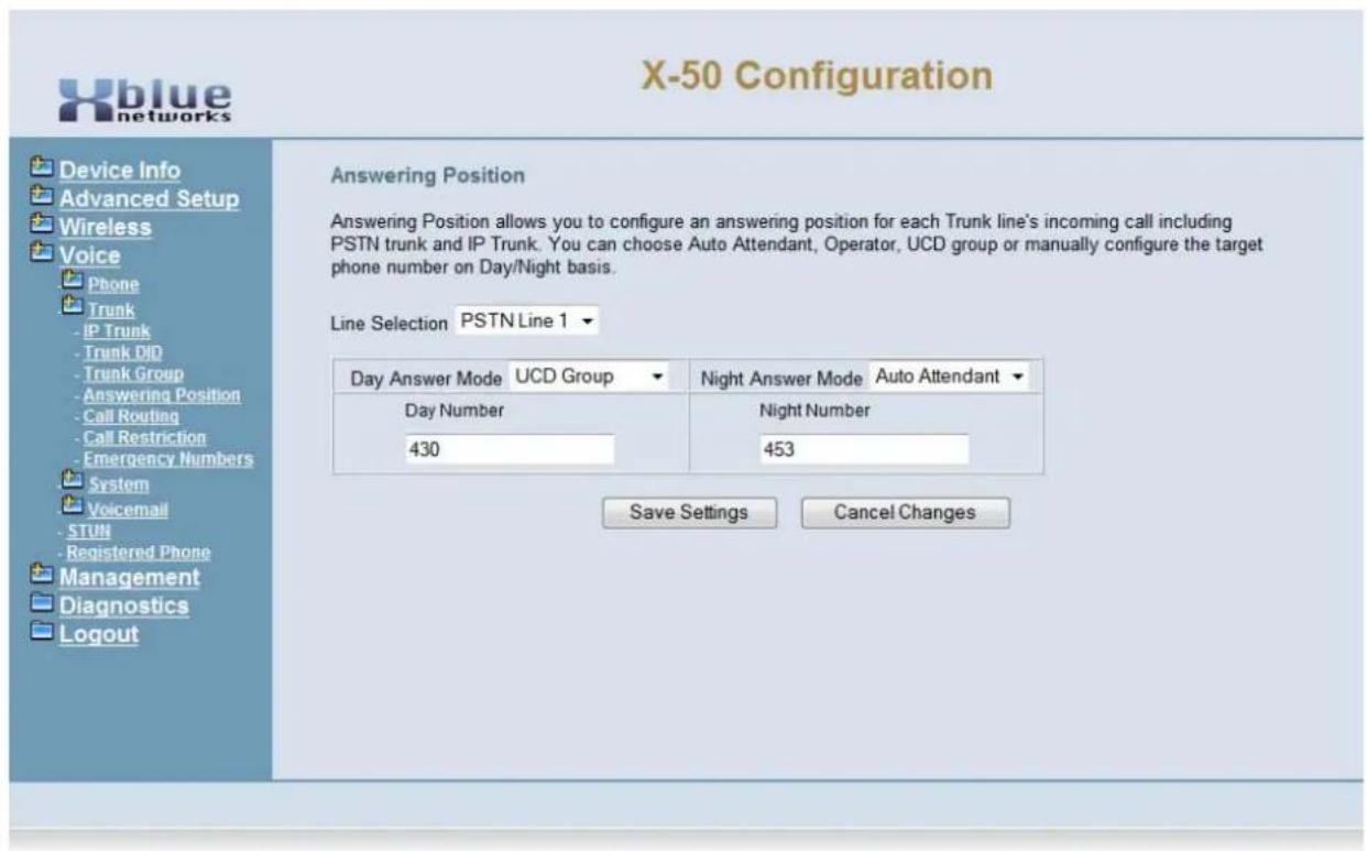
text_image
X-50 Configuration Device Info Advanced Setup Wireless Voice Phone Trunk IP Trunk Trunk DJD Trunk Group Answering Position Call Routing Call Restriction Emergency Numbers System Voicemail STUN Registered Phone Management Diagnostics Logout Answering Position Answering Position allows you to configure an answering position for each Trunk line's incoming call including PSTN trunk and IP Trunk. You can choose Auto Attendant, Operator, UCD group or manually configure the target phone number on Day/Night basis. Line Selection PSTN Line 1 Day Answer Mode UCD Group Night Answer Mode Auto Attendant Day Number Night Number 430 453 Save Settings Cancel Changes• Line Selection - Select the trunk to be modified
- Select between the four (4) answering positions for day and for night
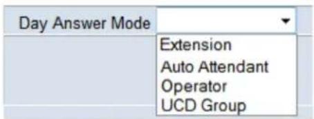
text_image
Day Answer Mode Extension Auto Attendant Operator UCD Group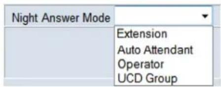
text_image
Night Answer Mode Extension Auto Attendant Operator UCD Group- Extension - The extension setting can have one of the 25 extension (24 SIP and 1 SLT) set to ring when a call is placed into the system.
-
Auto Attendant - The X-50 can be programmed to answer with an automated (receptionist) attendant, which can answer calls and allow them to dial their desired location. Each call is answered by a day or night outgoing message (OGM), which will play depending on the time of day and day of week.
-
- Operator - In system programming, one extension can be programmed as the system operator. This is the extension that will ring when another extension dials zero "0".
- UCD Group - Similar to hunt group, the UCD group can be programmed to ring all extensions at one time (All Ring), hunt for the extension that is onhook and idle the longest (Distributed), or hunt for the first extension that is idle within the group (Linear). When set to Linear, a no answer time, if enabled, will determine when to hunt to the next extension. See System - Numbering Plan (see page 187) to set up UCD Groups.
Call Routing Rules
Call Routing is used to automatically direct dialed numbers through a specific trunk, trunk group, or through another X-50 system. The rule will only be followed if all aspects of the rule are "true", otherwise it is ignored. Enter the information that will make up the rule and press "Add".
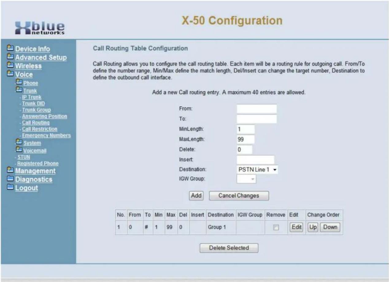
text_image
X-50 Configuration Device Info Advanced Setup Wireless Voice Phone Trunk - IP Trunk - Trunk DID - Trunk Group - Answering Position - Call Routing - Call Restriction - Emergency Numbers System Voicemail - STUN - Registered Phone Management Diagnostics Logout Call Routing Table Configuration Call Routing allows you to configure the call routing table. Each item will be a routing rule for outgoing call. From/To define the number range, Min/Max define the match length, Del/Insert can change the target number, Destination to define the outbound call interface. Add a new Call routing entry. A maximum 40 entries are allowed. From: To: MinLength: 1 MaxLength: 99 Delete: 0 Insert: Destination: PSTN Line 1 IGW Group: Add Cancel Changes No. From To Min Max Del Insert Destination IGW Group Remove Edit Change Order 1 0 # 1 99 0 Group 1 Edit Up Down Delete Selected- From - This is the lowest digit or digits that will be affected by this Call routing rule.
- To - This is the highest digit or digits that will be affected by this call routing rule.
- MinLength - the minimum number of digits to be used by this call routing rule.
- MAXLengh - The maximum number of digits to be used by this routing rule.
- Delete - This is the number of digits that will be deleted when the rule is found to be true. For example, when rerouting a dialed number that was dialed for long distance to a local line, the first four (4) digits 1 + XXX should be deleted, so the number will be set to four (4).
- Insert - Enter the digits that should prefix, be dialed before the actual dialed digits. For example, in some cases, it is cheaper to pay long distance prices, rather than local long distance, so the call can be redirected over the long distance telephone lines by adding 1 + XXX.
- Destination - Select the line that will be used when the rule is found to be true. IGW is used when the system is part of an overall voice network.
- IGW Group - The IGW Group is activated when the destination is set to IGW Group. Use the drop down menu to select the system where callers should be sent when the entered digits are dialed.

text_image
ClueFor proper operation of Call Log - Dialed, Missed, and Received Calls, the home area code, and automatic long distance insert, must be programmed into the Call Routing Table.
Enter the home area code, where the system is located, such as 913 in the "From" and "To", then the maximum and minimum digits dialed will be 10, in both, then enter 3 digits to be deleted by the system before the number is dialed. Do not enter any digits into the "Delete" parameter if all 10 digits should be dialed. Therefore, when a number in the entered area code is dialed, the area code if there is an entry in the delete parameter, in the example, 913, will be delete. The remaining 7 digits will be dialed.
The second entry will automatically enter a 1 for all other 10 digit numbers. Enter "From 2", "To 9", Min=10, Max=10, Insert=1, and "Group" default is 1. When any number that begins with 2 through 9, except 913, will receive a 1, when it is sent to the telephone line.
Kansas
| No. | From | To | Min | Max | Del | Insert | Destination | IGW Group | Remove | Edit | Change Order |
| 1 | 913 | 913 | 10 | 10 | 3 | Group 1 | Edit | Up Down | |||
| 2 | 2 | 9 | 10 | 10 | 0 | 1 | Group 1 | Edit | Up Down | ||
| 3 | 0 | # | 1 | 99 | 0 | Group 1 | Edit | Up Down |
In Scottsdale Arizona, for example, any 10 digit number that is dialed with 480 as the first three digits, 480 will be deleted. Any 10 digit number that has 602 and 623 as an area code, all 10 digits will be dialed. All other 10 digit numbers regardless of area code will receive a 1 before sending the call to the telephone line.
Scottsdale, AZ
| No. | From | To | Min | Max | Del | Insert | Destination | IGW Group | Remove | Edit | Change Order |
| 1 | 480 | 480 | 10 | 10 | 3 | Group 1 | Edit | Up Down | |||
| 2 | 602 | 602 | 10 | 10 | 0 | Group 1 | Edit | Up Down | |||
| 3 | 623 | 623 | 10 | 10 | 0 | Group 1 | Edit | Up Down | |||
| 4 | 2 | 9 | 10 | 10 | 0 | 1 | Group 1 | Edit | Up Down | ||
| 5 | 0 | # | 1 | 99 | 0 | Group 1 | Edit | Up Down |
Call Restriction Rules
The call restriction table allows the administrator to enter up to 13 digits that when dialed can be allowed or denied. The X-50 system allows the administrator to select which tables' rules will be referenced first the allow or the deny table.
If the priority is set to "Denied" the system will use the following rule:
- If the dialed number matches an entry in the deny table, the call is denied. Otherwise, the call is sent to the allow table.
- If the dialed number matches an entry in the allow table, the call is allowed. Otherwise, the call is denied.
If the priority is set to "Allow" the system will use the following rule:
- If the dialed number matches an entry in the allow table, the call is allowed. Otherwise, the call is sent to the deny table.
- If the dialed number matches an entry in the deny table, the call is denied, otherwise the call is allowed.
If there are entries in only the allow table, calls will be processed using the following rule:
- Calls in the allow table will be allowed - all other calls will be denied.
If there are entries in only the deny table, calls will be processed using the following rule:
- Calls in the deny table will be denied - all other calls will be allowed.
Use the restriction rules to establish dialing privileges for the 7 classes of service.
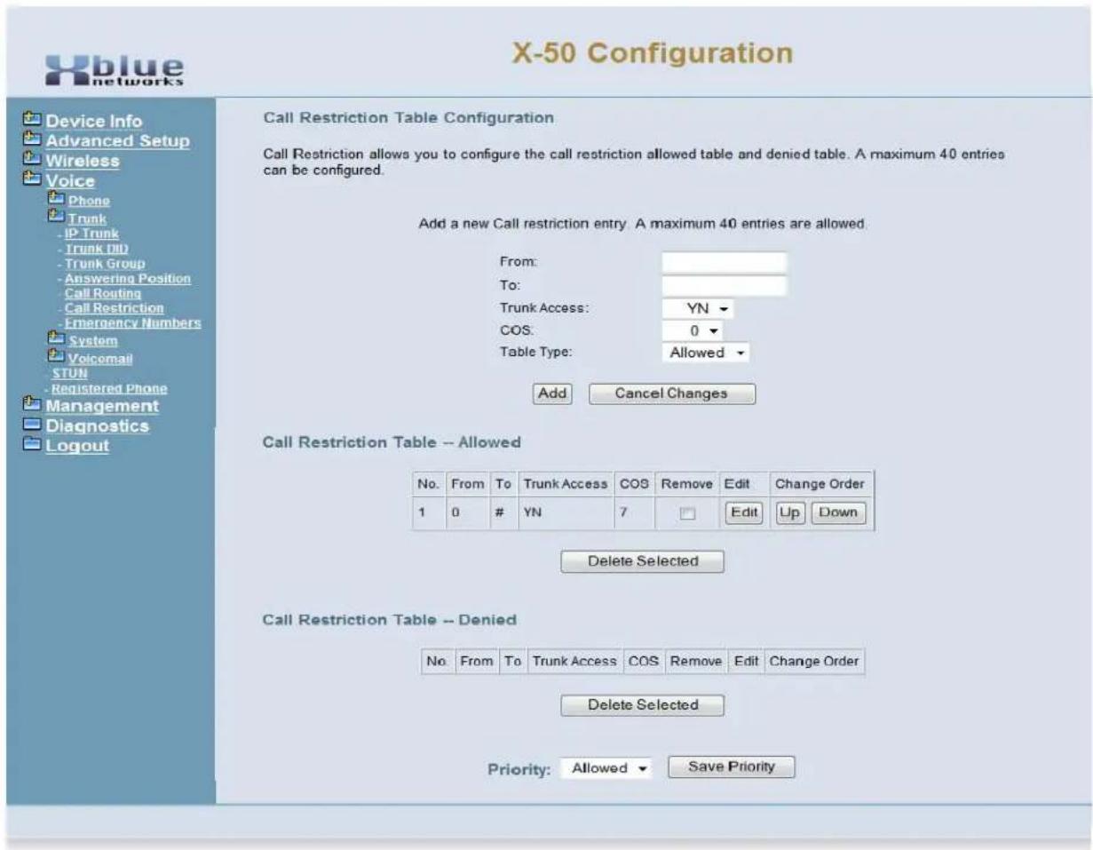
text_image
X-50 Configuration Device Info Advanced Setup Wireless Voice Phone Trunk - IP Trunk - Trunk DID - Trunk Group - Answering Position Call Routing - Call Restriction - Emergency Numbers System Volcomail STUN - Registered Phone Management Diagnostics Logout Call Restriction Table - Allowed Call Restriction Table - Denied Add a new Call restriction entry. A maximum 40 entries are allowed. From: To: Trunk Access: YN ▼ COS: 0 ▼ Table Type: Allowed ▼ Add Cancel Changes No. From To Trunk Access COS Remove Edit Change Order 1 0 # YN 7 Edit Up Down Delete Selected No. From To Trunk Access COS Remove Edit Change Order Delete Selected Priority: Allowed ▼ Save Priority- From - Enter up to 13 digits that will be used as the beginning of the evaluation number.
- To - Enter up to 13 digits that will be used as the ending of the evaluation number.
- Trunk Access (Yes/No) - This allows or deny's the call to have access to a Trunk, when the digits are dialed.
- COS - Class of Service - Select the Class of Service that will be applied to a call that matches the entry.
Routing Emergency Numbers

X-50 Configuration

Phone Trunk
- IP Trunk
- Trunk DID
-Trunk Group
-Answering Position
- Call Routing
- Call Restriction
Emergency Numbers
System Voicemail STUN
Registered Phone
Emergency Numbers
This page allows you configure five emergency call numbers and lines with which emergency calls are sent out.
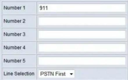
text_image
Number 1 911 Number 2 Number 3 Number 4 Number 5 Line Selection PSTN First ▼Save Settings
Cancel Changes
- Each system can evaluate up to five different numbers. If a match is found, the call will be sent through the "Line Selection" parameter.
- Using the drop down menu, select which way the call should be directed when a match is found. Calls can be directed through the first PSTN line, First SIP Trunk or through an idle PSTN lines.
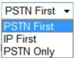
text_image
PSTN First PSTN First IP First PSTN OnlySystem
- Device Info
- Advanced Setup
- Wireless
-
Voice
-
- Phone
-
- Trunk
-
- System
- Numbering Plan
- Service Mode
- Transmission
- IGW Group
- SMDR
- UCD Call Log
• + Voicemail
- Registered Phone
- Management
- Diagnostics
- Logout
During the Setup Wizard, some of the default Numbering settings may have been changed. Therefore, this manual will show what the defaults are without any changes from the Setup Wizard.
Numbering Plan

X-50 Configuration
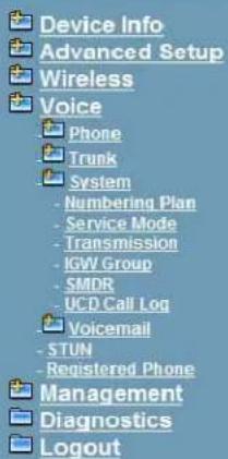
text_image
Device Info Advanced Setup Wireless Voice Phone Trunk System - Numbering Plan - Service Mode - Transmission - IGW Group - SMDR - UCD Call Log Voicemail - STUN - Registered Phone Management Diagnostics LogoutNumbering Plan Numbering Plan allows you to configure the extension number range. You can define the special extension number or service number. These settings will take effect after the system reboot.
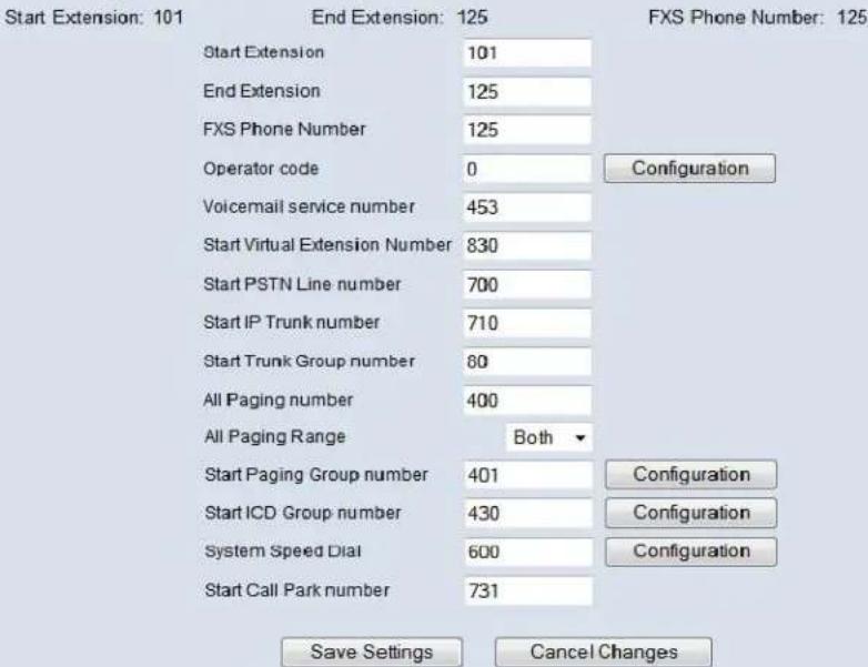
text_image
Start Extension: 101 End Extension: 125 FXS Phone Number: 125 Start Extension 101 End Extension 125 FXS Phone Number 125 Operator code 0 Configuration Voicemail service number 453 Start Virtual Extension Number 830 Start PSTN Line number 700 Start IP Trunk number 710 Start Trunk Group number 60 All Paging number 400 All Paging Range Both ▼ Start Paging Group number 401 Configuration Start ICD Group number 430 Configuration System Speed Dial 600 Configuration Start Call Park number 731 Save Settings Cancel Changes- Start Extension - Enter the beginning extension number for the system.
- End Extension - Enter the ending extension number for the system. If the number does not fall between the start and end number, it is considered an invalid extension.
- FXS Phone Number - Enter the analog or single line number that will be dialed to ring the single telephone number. The number must be within the start and end extension numbers.
- Operator speed-dial number, at default is set to Zero (0) and can be directed to any extension within the numbering plan. At default the extension is set to 101 for both day and night, but can be changed by pressing the configuraiton button.
The operator extension can be set to any number within the numbering plan.

text_image
X-50 Configuration Device Info Advanced Setup Wireless Voice Phone Trunk System - Numbering Plan - Service Mode - Transmission - IGW Group - SMDR - UCD Call Log Voicemail - STUN - Registered Phone Management Diagnostics Logout Operator Configuration This page allows you to configure the operator-related settings Operator day 101 Operator night 101 Alternate Operator day Alternate Operator night Reroute Time 0 (0, 15~180) Back Save Settings Cancel Changes- The day and a night operator can be the same or different extension numbers. The entered extension number will be accessed when an extension dials zero (0).
- A day and a night alternate operator can also be assigned. They can be the same or different numbers. The Alternate operator will automatically begin ringing if the call goes unanswered by the operator extension.
- Reroute Time - is the amount of time that a call will ring at the operator extension before ringing the alternate extension. When set to unlimited, the call will not forward. The timer can be set from 15 to 180 seconds. If the alternate attendant does not answer the call, and this timer is greater than zero (0) the call will go to the operator mailbox.
Press "Save Settings" to save the programming and "Back" to return to the main Numbering Plan Programming page.
- Voicemail Service Number - Is the pilot number that will be dialed to ring one of the four voice mail ports.
- Start PSTN Line Number - The X-50 has 6 PSTN lines, numbered 701, 701,702, 703, 704 and 705.
- Start IP Trunk Number - The X-50 has 8 SIP Trunks, number 711, 712, 713, 714, 715, 716, 717 and 718.
- There are 4 trunk group numbers, 80, 81, 82 and 83, each can have one or more trunks, with a combination of PSTN and/or SIP Trunks.
- All Paging Group - Dial this code to page all extensions in the system.
- Range - LAN, WAN and/or Both (All extensions must be in the same subnet)
- Start Paging Group Number - The X-50 has three paging groups, each with the ability to have up to 24 LAN, WAN or both extension types.
Enter up to 24 extensions in a group.
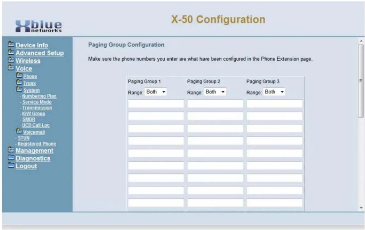
text_image
X-50 Configuration Device Info Advanced Setup Wireless Voice Phone Trunk System - Numbering Plan - Service Mode - Transmission - IGW Group - SMDR - UCD Call Log Voicemail - STUN - Registered Phone Management Diagnostics Logout Paging Group Configuration Make sure the phone numbers you enter are what have been configured in the Phone Extension page. Paging Group 1 Paging Group 2 Paging Group 3 Range: Both Range: Both Range: Both Paging Group 1 Paging Group 2 Paging Group 3 Range: Both Range: Both Range: Both 视为 视为 视为 视为 视为 视为 视为 视为 视为 视为 视为 视为 视为 视为 视为 视为 视为 视为 视为 视为 视为 视为 视为 视为 视为 视为 视为 视为 视为 视为 视为 视为 视为 视为 视为 视为 视为 视为 视为 视为 视为 视为 视为 视为 视为 视为 视为 视为 视为 视为 verse 视为 视为 视为 视为 视为 视为 视为 视为 视为 视为 视为 视为 视为 视为 视为 视为 视为 视为 视为 视为 视为 视为 视为 视为 视为 视为 视为 视为 视为 视为 视为 视为 视为 视为 视为 视为 视为 视为 视为 视为 视为 视为 视为 视为 视为 视为 视为 视为 视为 视为 verse- Using the drop down menu, select LAN/WAN or Both (all extensions must be in the same subnet).
- Enter the up to 24 SIP telephone extension numbers -
Press "Save Settings" to save the programming and "Back" to return to the main Numbering Plan Programming page.
• UCD Group - Uniform Call Distribution Group also known as a Hunt or UCD group.
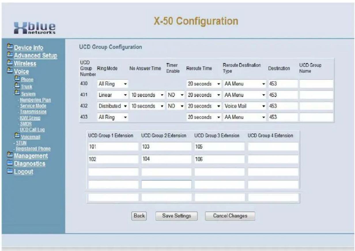
text_image
X-50 Configuration Device Info Advanced Setup Wireless Voice Phone Trunk System - Numbering Plan - Service Mode - Transmission - IGW Group - SMDR - UCD Call Log Voicemail - STUN - Registered Phone Management Diagnostics Logout UCD Group Configuration UCD Group 1 Extension UCD Group 2 Extension UCD Group 3 Extension UCD Group 4 Extension 101 103 105 102 104 106 Back Save Settings Cancel Changes- The X-50 has 4 UCD groups, each can be programmed as an All Ring (rings all extensions within the group), Linear (if a busy extension is found it will hunt to another group, but will not continue to hunt if the extension rings), or Distributed (rings the extension that is on-hook and idle the longest.
- No Answer Time - The no answer time becomes active when a group is defined as Linear or Distributive. The timer is adjustable between 10 and 120 seconds. This timer is not active when set to "All Ring".
- Timer Enable - The No Answer Timer (when set to either Linear or Distributive) the timer can be enabled or disabled.
- Reroute Time - At the expiration of the Reroute Time the call will be routed to the reroute destination. The timer is adjustable from 10 to 120 seconds.
- Reroute Destination - Calls can be rerouted to the main auto attendant, or to Voicemail.
• UCD Group Name - Each UCD group can be labeled with a different name.
- Speed Dial - The X-50 has 100 system speed bins which can be accessed by all extensions within the system. Each programmed Speed Dial can be set to reference the extensions' class of service before dialing the number.
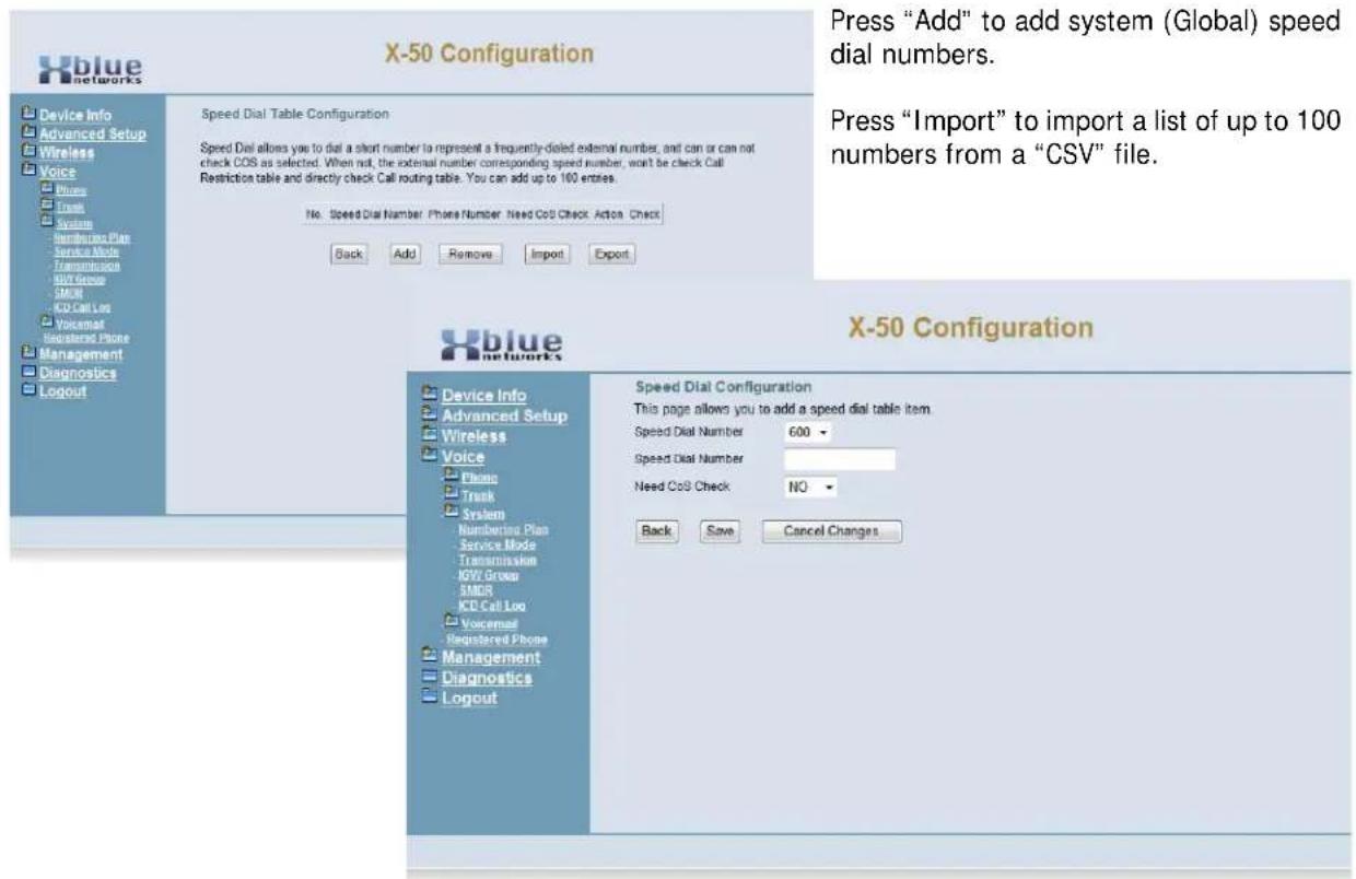
text_image
X-50 Configuration Speed Dial Table Configuration Speed Dial allows you to dial a short number to represent a frequently-dialed external number, and can or can not check COS as selected. When not, the external number corresponding speed number, won't be check Call Restriction table and directly check Call routing table. You can add up to 100 entries. No. Speed Dial Number Phone Number Need Cos Check Action Check Back Add Remove Import Export X-50 Configuration Device Info Advanced Setup Wireless Voice Phone Trunk System Numbering Plan Service Mode Transmission IGW Group SMDR KCD Call Log Voicemail Registered Phone Management Diagnostics Logout Speed Dial Configuration This page allows you to add a speed dial table item. Speed Dial Number 600 Speed Dial Number Need Cos Check NO Back Save Cancel ChangesPress "Save Settings" to save the programming and "Back" to return to the main Numbering Plan Programming page.
- Start Call Park Number - The X-50 system allows calls to be placed into a park or orbit location in the system allowing all extensions to have access to the call.
Service Mode
There are three service modes; Day (the system remains in day mode), Night (the system remains in night mode), or timed (the system automatically changes between day and night modes) based on the Service Mode Configuration. Enter the time in eight digit twenty-four hour format.
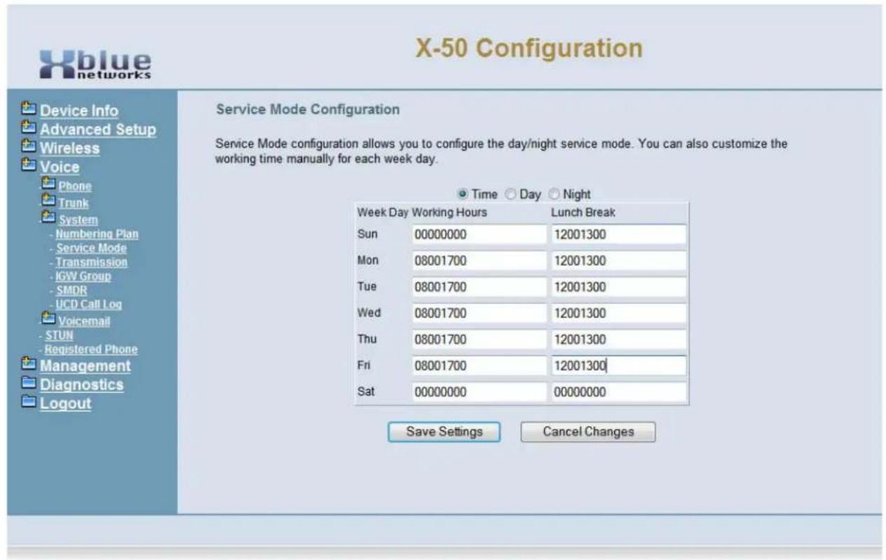
text_image
X-50 Configuration Device Info Advanced Setup Wireless Voice Phone Trunk System - Numbering Plan - Service Mode - Transmission - IGW Group - SMDR - UCD Call Log Voicemail - STUN - Registered Phone Management Diagnostics Logout Service Mode Configuration Service Mode configuration allows you to configure the day/night service mode. You can also customize the working time manually for each week day. Time Day Night Week Day Working Hours Lunch Break Sun 00000000 12001300 Mon 08001700 12001300 Tue 08001700 12001300 Wed 08001700 12001300 Thu 08001700 12001300 Fri 08001700 12001300 Sat 00000000 00000000 Save Settings Cancel Changes- Define each day with a "Start" and an "End" time. A start time of 00:00 and an end time of 00:00 results in no change of status.
• The system can be placed into Day Mode
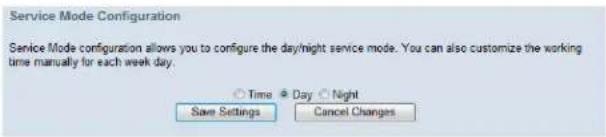
text_image
Service Mode Configuration Service Mode configuration allows you to configure the day/night service mode. You can also customize the working time manually for each week day. ○ Time ○ Day ○ Night Save Settings Cancel Changes• The system can be placed into Night Mode
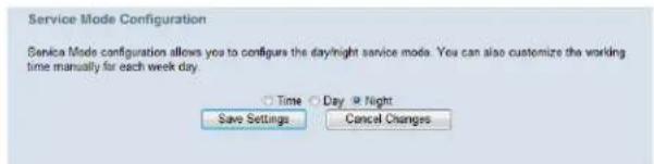
text_image
Service Mode Configuration Service Mode configuration allows you to configure the day/night service mode. You can also customize the working time manually for each week day. ○ Time ○ Day ● Night Save Settings Cancel ChangesTransmission
The transmission area of programming is used to set the country that the unit will be installed and the signalling protocol that will be used. At default, the X-50 is set to North America.
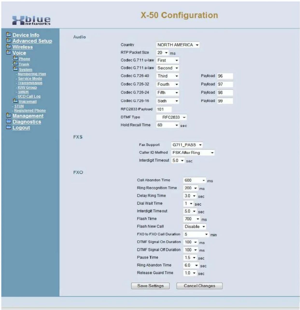
text_image
X-50 Configuration Device Info Advanced Setup Wireless Voice Phone Trunk System - Numbering Plan - Service Mode - Transmission - IGW Group - SMUR - UCD Call Log Voicemail - STUN - Registered Phone Management Diagnostics Logout Audio Country NORTH AMERICA RTP Packet Size 20 ms Codec G.711 u-law First Codec G.711 a-law Second Codec G.726-40 Third Payload 96 Codec G.726-32 Fourth Payload 97 Codec G.726-24 Fifth Payload 98 Codec G.726-16 Sixth Payload 99 RFC2833 Payload 101 DTMF Type RFC2833 Hold Recall Time 60 sec FXS Fax Support G711_PASS Caller ID Method FSK After Ring Interdigit Timeout 5.0 sec FXO Call Abandon Time 600 ms Ring Recognition Time 200 ms Delay Ring Time 3.0 sec Dial Wait Time 1 sec Interdigit Timeout 5.0 sec Flash Time 700 ms Flash New Call Disable FXO to FXO Call Duration 5 min DTMF Signal On Duration 100 ms DTMF Signal Off Duration 100 ms Pause Time 1.5 sec Ring Abandon Time 6.0 sec Release Guard Time 1.0 sec Save Settings Cancel ChangesAudio
- Country - North America, UK, Japan, Sweden, Germany, France, Belgium, Finland, Italy, Netherlands, China, Spain
- RTP Packet Size - (Real-time Transport Protocol) defines a standardized packet format for delivering audio and video over IP networks. The default is set to 20, and is adjustable from 10 to 60 milliseconds.
- Codec settings - Set the order that each Codec will be used. When the system gets busier, it will automatically increase the compression, to decrease the traffic (voice over IP packets), to ensure that all of the calls can be completed with the best possible voice quality.
Codec Priority Payload Compression
| G.711 u-law First Low | ||
| G.711 a-law Second Low | ||
| G.726-40 Third 96 Low - Medium | ||
| G.726-32 Forth 97 Medium | ||
| G.726-24 Fifth | 98 Medium High | |
| G.726-16 Sixth | 99 High | |
| RFC 2833 | G.729 audio data compression 10 ms duration | |
- DTMF Type - Select between transmitting DTMF tone or SIP-INFO method. Generally, this will be set to DTMF Type.
- Hold Recall Time - The recall feature pertains to calls that are parked, on hold, or calls that have been transferred to another extension. Calls which go unanswered after the preprogrammed time are "Recalled" to the extension which initiated the park, hold or transfer. This timer is used to ensure that calls do not go unattended. At default, the timer is set to 60 seconds, and can be adjusted to 30, 60, 90, 120, 150, 180, 210, 240, 270, 300.
FXS (Single Line Telephone)
- FAX Support - (also known as Fax Detection) can be set to either G711_Pass (passes the signal directly through the system) or T38 allows fax transmission, in real time, over an IP Network.
- Caller ID Method - Caller ID, in the US, is a FSK signal that is passed between the first and second ring. However, the X-50 has the ability to compensate for other types of Caller ID Protocol - FSK before ring, FSK after ring, DTMF before ring, DTMF after ring.
- Interdigit Timeout - At default the X-50 is set to 5 seconds, and adjustable from 2 to 9 seconds.
FXO (Telephone (Trunk) Line)
- Call Abandon Time - This is the timer that the system uses to verify the At default the call abandon timer is set to 600 ms, and is adjustable from - Disabled, and 100 to 1000 ms. Changing this may cause erratic operation.
- Ring Recognition Time - This timer determines the minimum ring signal detection time for all analog telephone lines. Changing this may cause erratic operation.
- Delay Ring Time - This timer determines the amount of time that the system will wait before the system begins audibly ringing. Changing this may cause erratic operation.
- Dial Wait Time - This parameter is to compensate for older telephone line providers, which are slow to process the first digit dialed. Changing this parameter may cause erratic operation.
- Interdigit Timeout - This timer is the amount of time that will be allowed to pass between digits dialed.
- Flash Time - This timer determines the flash timing that will be sent to the telephone line provider when the user presses the hook-switch.
- Flash New Call - Enable/Disable - This allows the administrator to grant or deny system users the ability to flash the telephone line to “renew” dial tone and allow the caller to start dialing. Disabling this feature will disable call waiting.
- FXO to FXO Call Duration - This time establishes the amount of time two telephone lines can be conferred together before the call is disconnected. The default is 5 minutes, and is adjustable from 1 to 15 minutes plus unlimited. Note: It is not advised or recommended to set this timer to “unlimited”.
- DTMF Signal on Duration - This is the amount of time that the DTMF tone will audibly play.
- DTMF Signal off Duration - The is the amount of time that will pass between between audible tones.
- Pause Time - The pause timer, which appears as a "P" is the amount of time that will pass between dialing functions.
- Ring Abandon Time - This timer gives the system the ability to match a telephone line provides' disconnect timer.
- Release Guard Time - This timer is a noise sensitivity adjustment timer used to eliminate false disconnects. At default it is set to 1.0 and can be set from 1.0, 1.5, 2.0, 2.5, 3.0. Increase this timer to ignore noise on the telephone lines to avoid erroneous disconnects.
Internet Gateway Group - Voice Network
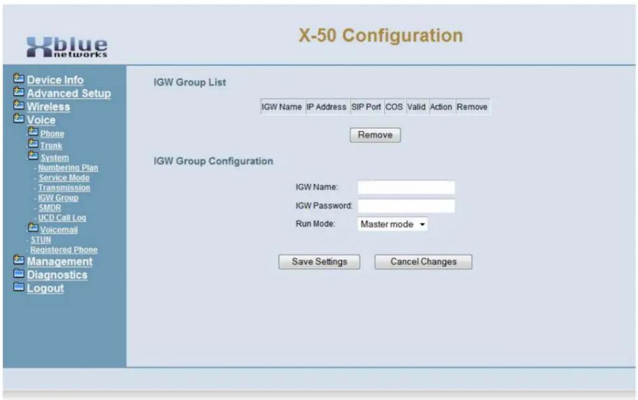
text_image
X-50 Configuration Device Info Advanced Setup Wireless Voice Phone Trunk System - Numbering Plan - Service Mode - Transmission - IGW Group - SMDR - UCD Call Log Voicemail - STUN - Registered Phone Management Diagnostics Logout IGW Group List IGW Name IP Address SIP Port COS Valid Action Remove Remove IGW Group Configuration IGW Name: IGW Password: Run Mode: Master mode ▼ Save Settings Cancel ChangesThis parameter is used when connecting multiple systems creating to create a voice Network or Campus Environment. The X-50 can be part of a 10 system voice network. One system is a "Master System" and requires a static IP Address the remaining 9 are "Slave" systems do not require static IP addresses.
- Gateway Name - Enter the name of the gateway.
- Enter the Gateway Password
- Select if the system will be a master or slave system.
Voice Network
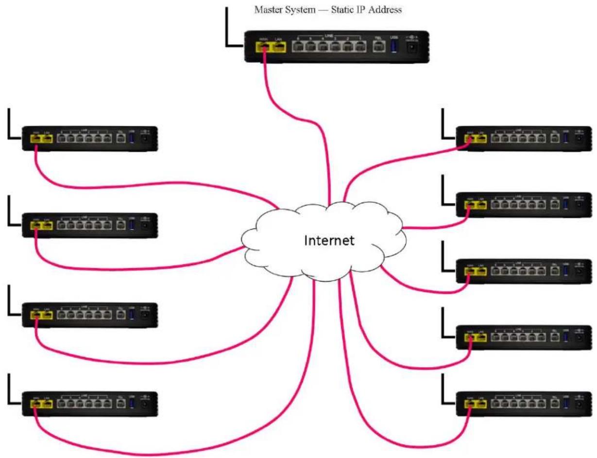
flowchart
graph TD
    A["Internet"] --> B["Master System — Static IP Address"]
    A --> C["1"]
    A --> D["2"]
    A --> E["3"]
    A --> F["4"]
    A --> G["5"]
    A --> H["6"]
    A --> I["7"]
    A --> J["8"]
    A --> K["9"]
    A --> L["10"]
    A --> M["11"]
    A --> N["12"]
    A --> O["13"]
    A --> P["14"]
    A --> Q["15"]
    A --> R["16"]
    A --> S["17"]
    A --> T["18"]
    A --> U["19"]
    A --> V["20"]
Station Message Detail Recording (SMDR)
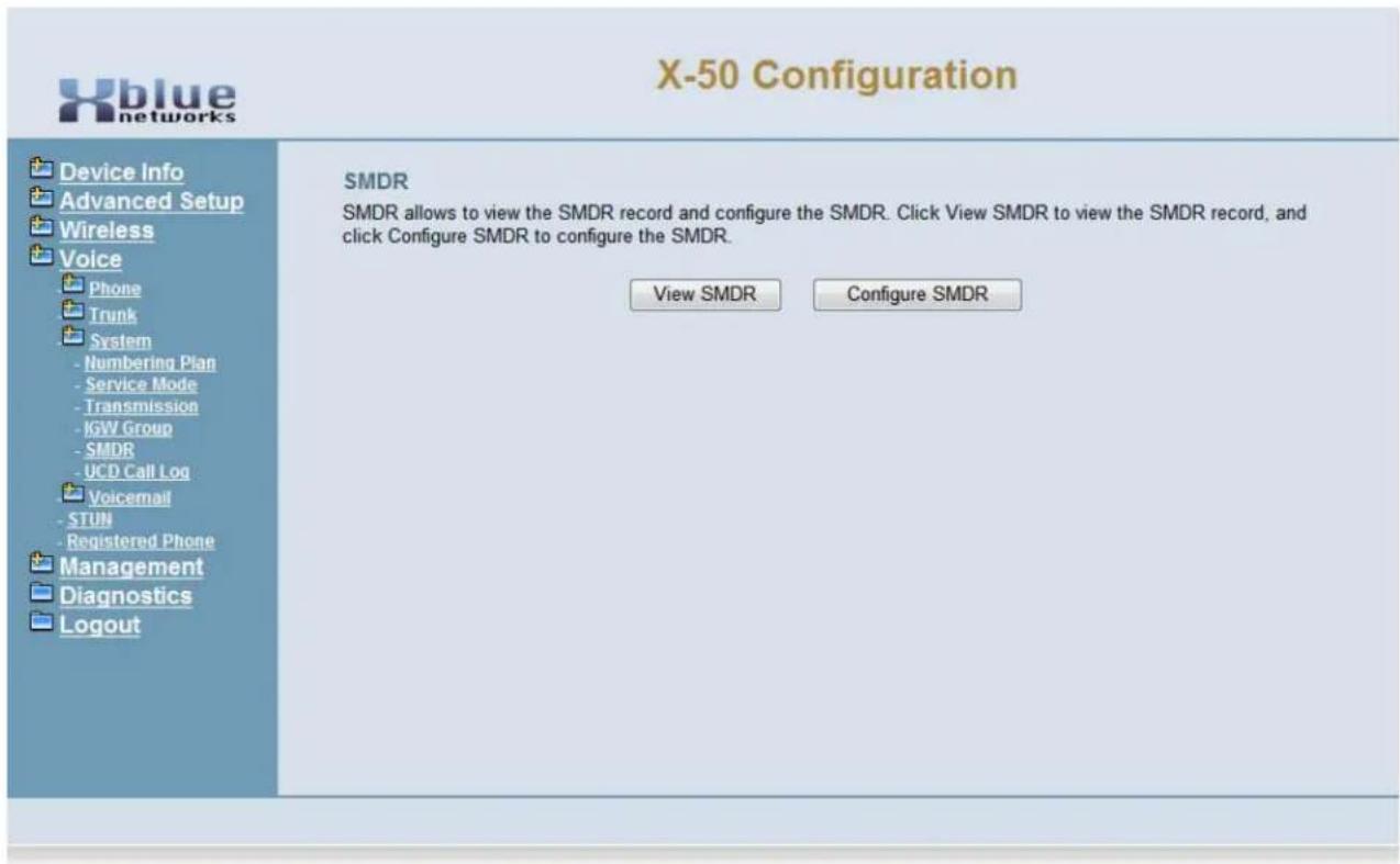
text_image
X-50 Configuration Device Info Advanced Setup Wireless Voice Phone Trunk System - Numbering Plan - Service Mode - Transmission - IGW Group - SMDR - UCD Call Log Voicemail - STUN - Registered Phone Management Diagnostics Logout SMDR SMDR allows to view the SMDR record and configure the SMDR. Click View SMDR to view the SMDR record, and click Configure SMDR to configure the SMDR. View SMDR Configure SMDRThe X-50 system has the ability to record call statics for incoming, outgoing, or both types of calls. Select View to review the list or configure, to configure how SMDR will be recorded in the system.
SMDR Configuration
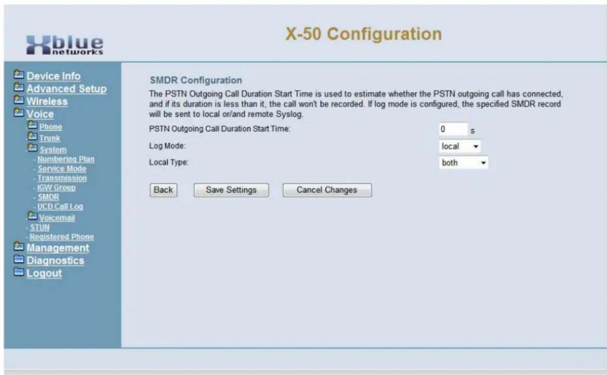
text_image
X-50 Configuration Device Info Advanced Setup Wireless Voice Phone Trunk System - Numbering Plan - Service Mode - Transmission - IGW Group - SMDR - UCD Call Log Voicemail - STUN - Registered Phone Management Diagnostics Logout SMDR Configuration The PSTN Outgoing Call Duration Start Time is used to estimate whether the PSTN outgoing call has connected, and if its duration is less than it, the call won't be recorded. If log mode is configured, the specified SMDR record will be sent to local or/and remote Syslog. PSTN Outgoing Call Duration Start Time: 0 s Log Mode: local Local Type: both Back Save Settings Cancel Changes- Start Time - A New SMDR record will be created after a call has been active for the entered time.
- Log Mode - Select between, local, remote, both to create a new SMDR record or enter None to disable SMDR.
SMDR View
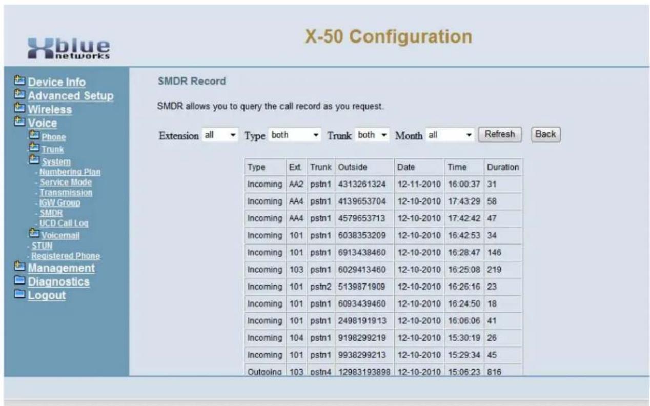
text_image
X-50 Configuration SMDR Record SMDR allows you to query the call record as you request. Extension all ▼ Type both ▼ Trunk both ▼ Month all ▼ Refresh Back Type Ext Trunk Outside Date Time Duration Incoming AA2 pstn1 4313261324 12-11-2010 16:00:37 31 Incoming AA4 pstn1 4139653704 12-10-2010 17:43:29 58 Incoming AA4 pstn1 4579653713 12-10-2010 17:42:42 47 Incoming 101 pstn1 6038353209 12-10-2010 16:42:53 34 Incoming 101 pstn1 6913438460 12-10-2010 16:28:47 146 Incoming 103 pstn1 6029413460 12-10-2010 16:25:08 219 Incoming 101 pstn2 5139871909 12-10-2010 16:26:16 23 Incoming 101 pstn1 6093439460 12-10-2010 16:24:50 18 Incoming 101 pstn1 2498191913 12-10-2010 16:06:06 41 Incoming 104 pstn1 9198299219 12-10-2010 15:30:19 26 Incoming 101 pstn1 9938299213 12-10-2010 15:29:34 45 Outgoing 103 pstn4 12983193898 12-10-2010 15:06:23 816- Extension - Select to report on all extensions or none of them.
- Type - Select to report on an Incoming or Outgoing call or Both.
- Trunk - Select to report on Just SIP Trunks, PSTN telephone lines or both
• Month - Report on all months (View only)
UCD Call Log
Uniform Call Distribution Group Report
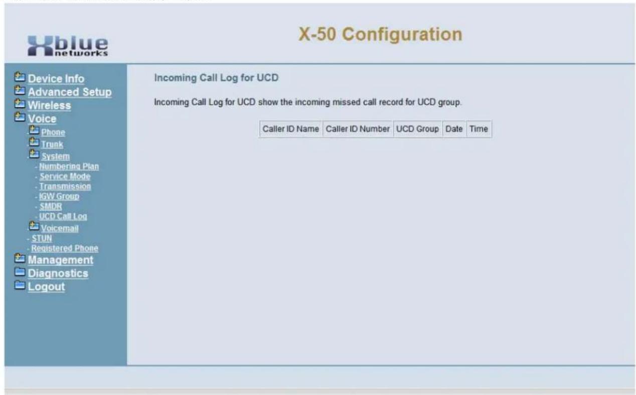
text_image
X-50 Configuration Device Info Advanced Setup Wireless Voice Phone Trunk System - Numbering Plan - Service Mode - Transmission - IGW Group - SMDR - UCD Call Log Voicemail - STUN - Registered Phone Management Diagnostics Logout Incoming Call Log for UCD Incoming Call Log for UCD show the incoming missed call record for UCD group. Caller ID Name Caller ID Number UCD Group Date TimeThe UCD Group, often called Unified Call Distribution or UCD, allows callers to ring into a group of "Agents", which can be internal or external (Remote Worker). This log shows any calls that were unanswered.
Voicemail
- Device Info
- Advanced Setup
- Wireless
- Voice
• + Phone -
- Trunk
• + System
• + Voicemail
- Trunk
- General
- Extension
- Holiday
- Advanced
-
Registered Phone
-
Management
- Diagnostics
- Logout
The X-50 system comes complete with an integrated Auto Attendant (Automated or Virtual Receptionist) and Voicemail system. The system can be programmed to answer with the Automated Attendant, bypassing the traditional attendant, allowing callers to dial digits and route their call to the appropriate destination. Each extension in the system can be assigned a mailbox so that they may receive private messages. In addition, the system can be programmed to E-mail a standard "WAV" file of the voicemail message.
Auto Attendant
Voicemail General Settings
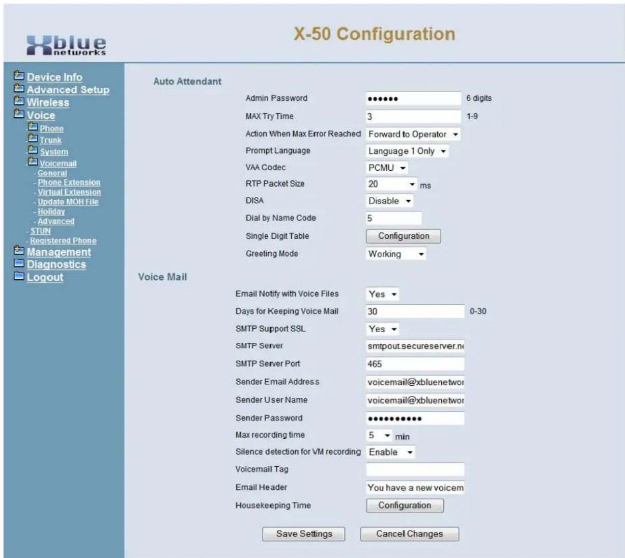
text_image
X-50 Configuration Device Info Advanced Setup Wireless Voice Phone Trunk System Voicemail - General - Phone Extension - Virtual Extension - Update MOH File - Holiday - Advanced - STUN - Registered Phone Management Diagnostics Logout Auto Attendant Admin Password 6 digits MAX Try Time 3 1-9 Action When Max Error Reached Forward to Operator Prompt Language Language 1 Only VAA Codec PCMU RTP Packet Size 20 ms DISA Disable Dial by Name Code 5 Single Digit Table Configuration Greeting Mode Working Voice Mail Email Notify with Voice Files Yes Days for Keeping Voice Mail 30 0-30 SMTP Support SSL Yes SMTP Server smtpout.secureserver.net SMTP Server Port 465 Sender Email Address voicemail@xbluenetwork Sender User Name voicemail@xbluenetwork Sender Password 0000000000000000000000000000000000000000000000000000000000000000000000000000000000000000000000000 Max recording time 5 min Silence detection for VM recording Enable Voicemail Tag Email Header You have a new voicem Housekeeping Time Configuration Save Settings Cancel Changes- Admin Password - At default, the X-50 systems' password is 000000. Highlight the password and then enter a new 6 digit (000000 - 999999) password. This password will also be used when accessing the administrator mailbox to record system outgoing message (OGM).
- MAX Try Time - Enter the number of times between 1 and 9 that a caller can enter wrong information before being sent to the Action When Max Error Reached.
- Action When MAX Error Reached - There are two destinations; forward to operator or disconnect.
-
Prompt Language - The system is equipped with two languages, english and Chinese.
-
VVA Code - The default is set to PCMU, the United States uses the PCMU codec, other countries use PCMA codec.
- RTP Packet Size - At default this is set to 20 ms, and is adjustable from "Dynamic, 10 - 60", but should remain set to 20 unless otherwise instructed.
- DISA - Direct Inward System Access - this feature, when enabled, allows inbound callers to enter a code and gain access to system features such as outbound calling. Note: Enabling this feature may result in unexpected long distance charges, which are the sole responsibility of the owner/user of the equipment.
- Dial by Name Code - Enter the code that will be used by callers, when dialing a persons name, once they are answered by the automated attendant. Once this code is selected, it will automatically reserve the entered number on all 10 menus.
Single Digit Dialing Table
The X-50 system is equipped with ten (10) Single Digit Dial Menus that allows the administrator to program menu trees which are a series of choices that a caller can dial to process their call more efficiently. For example, a main greeting may instruct the caller to dial 1 for sales, which accesses menu 2. Then the caller is instructed to dial 1 for Northeast Sales, 2 for Central Eastern Sales, Southeast Sales, etc.
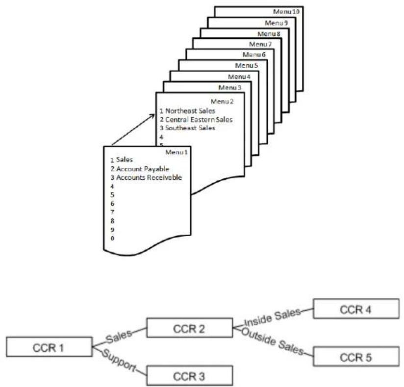
flowchart
graph TD
    A["Menu 1"] --> B["1 Northeast Sales"]
    A --> C["2 Central Eastern Sales"]
    A --> D["3 Southeast Sales"]
    A --> E["4"]
    A --> F["5"]
    G["Menu 2"] --> H["1 Northeast Sales"]
    G --> I["2 Central Eastern Sales"]
    G --> J["3 Southeast Sales"]
    G --> K["4"]
    G --> L["5"]
    M["Menu 3"] --> N["1 Northeast Sales"]
    M --> O["2 Central Eastern Sales"]
    M --> P["3 Southeast Sales"]
    M --> Q["4"]
    M --> R["5"]
    S["Menu 4"] --> T["1 Northeast Sales"]
    S --> U["2 Central Eastern Sales"]
    S --> V["3 Southeast Sales"]
    S --> W["4"]
    S --> X["5"]
    Y["Menu 5"] --> Z["1 Northeast Sales"]
    Y --> AA["2 Central Eastern Sales"]
    Y --> AB["3 Southeast Sales"]
    Y --> AC["4"]
    Y --> AD["5"]
    AE["Menu 6"] --> AF["1 Northeast Sales"]
    AE --> AG["2 Central Eastern Sales"]
    AE --> AH["3 Southeast Sales"]
    AE --> AI["4"]
    AE --> AJ["5"]
    AK["Menu 7"] --> AL["1 Northeast Sales"]
    AK --> AM["2 Central Eastern Sales"]
    AK --> AN["3 Southeast Sales"]
    AK --> AO["4"]
    AK --> AP["5"]
    AQ["Menu 8"] --> AR["1 Northeast Sales"]
    AQ --> AS["2 Central Eastern Sales"]
    AQ --> AT["3 Southeast Sales"]
    AQ --> AU["4"]
    AQ --> AV["5"]
    AW["Menu 9"] --> AX["1 Northeast Sales"]
    AW --> AY["2 Central Eastern Sales"]
    AW --> AZ["3 Southeast Sales"]
    AW --> BA["4"]
    AW --> BB["5"]
    BC["Menu 10"] --> BD["1 Northeast Sales"]
    BC --> BE["2 Central Eastern Sales"]
    BC --> BF["3 Southeast Sales"]
    BC --> BG["4"]
    BC --> BH["5"]
Click on the Single Digit Dialing table button to prgram the digits that callers will be instructed to dial.
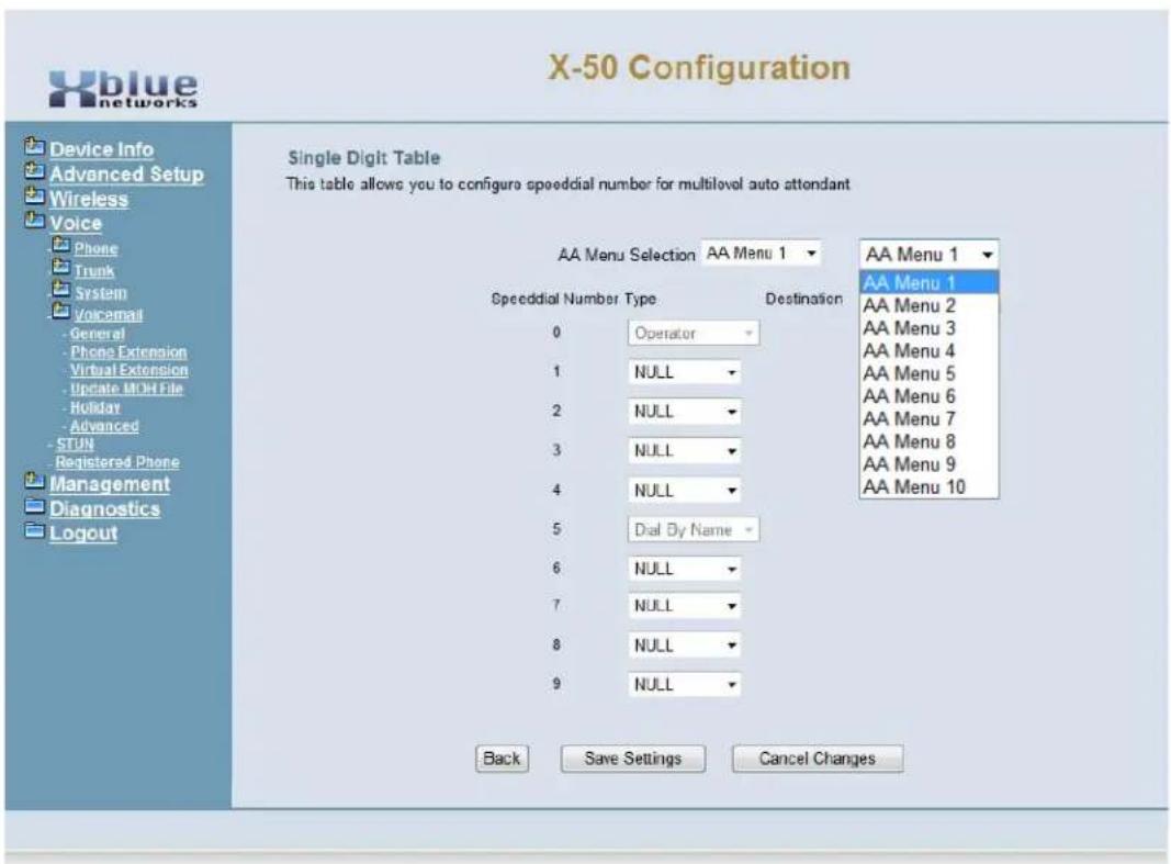
text_image
X-50 Configuration Device Info Advanced Setup Wireless Voice Phone Trunk System Voicemail General Phone Extension Virtual Extension Update MOH File Holiday Advanced STUN Registered Phone Management Diagnostics Logout Single Digit Table This table allows you to configure speeddial number for multilovel auto attendant AA Menu Selection AA Menu 1 ▼ Speeddial Number Type Destination 0 Operator 1 NULL 2 NULL 3 NULL 4 NULL 5 Dial By Name 6 NULL 7 NULL 8 NULL 9 NULL Back Save Settings Cancel Changes AA Menu 1 AA Menu 2 AA Menu 3 AA Menu 4 AA Menu 5 AA Menu 6 AA Menu 7 AA Menu 8 AA Menu 9 AA Menu 10- Using the dropdown box select the AA Menu to be programmed.
- Using the dropdown box select the destination for each number.
- Null - No action will be taken and the call will be prompted "You have pressed an invalid Digit".
- UCD - Enter the UCD number, which at default is 430, 431, 432 or 433 that will ring when the digit is pressed.
- Extension - Enter the extension number that will ring when the digit is pressed.
• AA Menu - Enter the voicemail dial code, which at default is 450, plus the Menu number 0 - 9.
TABLE 9.1 Enter 45 + N
| 45 + N | Menu Number | 45 + N | Menu Number | |
| 0 Menu 1 5 | Menu 6 | |||
| 1 Menu 2 6 | Menu 7 | |||
| 2 Menu 3 7 | Menu 8 | |||
| 3 Menu 4 8 | Menu 9 | |||
| 4 Menu 5 9 | Menu 10 | |||
Press the "Back" button to return to the "General" voicemail programming menu
- Greeting Mode - The system can be manually placed into Temporary or Holiday mode, or remain in working mode to allow the clock to automatically switch between Day, Night and Holiday modes.
Voicemail
- E-mail Notify with Voice Files - Also known as “E-mail Delivery” or “Unified Messaging”. When a new voicemail message is left in an extension with e-mail delivery set to “Yes” a standard “WAV” file will be created and e-mailed to the entered e-mail address. This requires access to the network and an e-mail server or e-mail address.
- Days for keeping Voice Mail - This is the maximum number of days that any voice mail message will be kept on the system. At default it is set to 30 so, on the 31st day, messages from the first day will be automatically deleted.
- SMTP Support SSL - When set to "Yes" the voice mail will be required to authenticate with the e-mail server before it can send an e-mail message.
- SMTP Server - Enter the STMP server that will be accessed when sending a e-mail of a new voice message.

text_image
ClueIf the SMTP server is unknown, locate a computer on the network and open their e-mail client. If using Outlook or Outlook express go to "Tools" and select "Account Settings". Click on the e-mail the address and locate "Outgoing e-mail Server" and make a note of the address.
Also, to locate the SMTP Server Port - click on "More Settings" and then click on the "Advacned" Tab, and locate the "Outgoing SMTP" Port and make a note of the port. This will be needed the next step.
- SMTP Server Port - Enter the SMTP port that will be used when accessing the SMTP server. Some common ports are 25, 80, 465 and 995.
- Sender E-mail Address - Enter the e-mail address that will be used when sending a new voice mail message. If possible, a new e-mail address, which resembles "voicemail@yourcompany.com" can be created making the sender's voice mailbox consistent.
- Sender User Name - This is the name that is used to authenticate the sender before being able to send an e-mail using the entered SMTP server. This entry may resemble the sender e-mail address.
- Sender Password - This is the password that is used to authenticate the sender before being able to send an e-mail using the entered SMTP server.
- Max Recording Time - This is the maximum recording time for a voice mail message. Once this timer is reached the caller will be disconnected and the message will be sent. At default this timer is set to 1 minutes and is adjustable from 1 to 30 minutes.
- Silence Detection for VM recording - This allows the system to monitor new voice mail messaged for silence. Once the silence time is reached, the voicemail will prompt the caller to enter a DTMF Digit to continue. If no DTMF tone is entered, the call will be disconnected.
• Voicemail Taq - The tag is what is shown when an E-mail arrives at its destination. - E-mail Header - The header is the information that is shown on the "Subject" line of the E-mail.
House Keeping
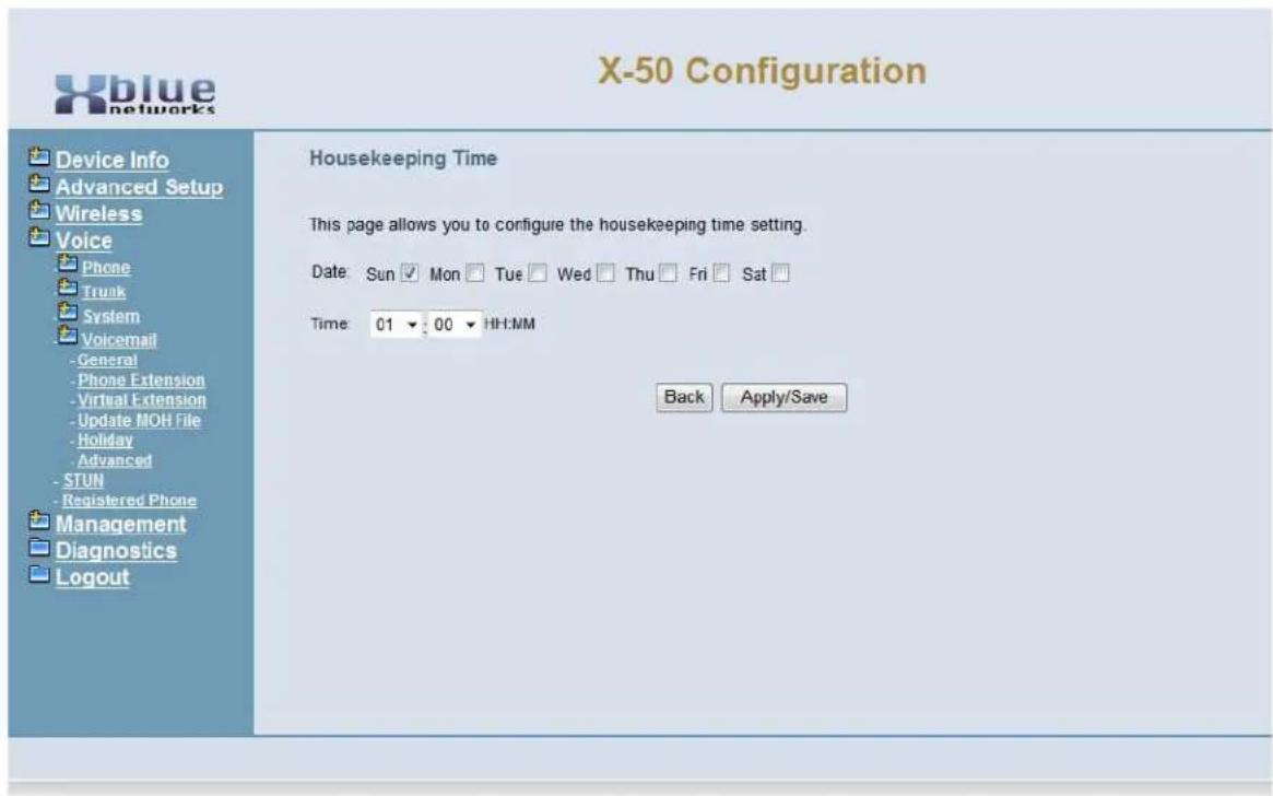
text_image
X-50 Configuration Device Info Advanced Setup Wireless Voice Phone Trunk System Voicemail -General Phone Extension Virtual Extension Update MOH File Holiday Advanced STUN Registered Phone Management Diagnostics Logout Housekeeping Time This page allows you to configure the housekeeping time setting. Date: Sun Mon Tue Wed Thu Fri Sat Time: 01 00 HH:MM Back Apply/Save- Select the time of day and day of week that the system should do maintenance, deleting old messages and doublechecking message waiting indication, etc.
Phone Extension
Each SIP telephone connected to the system has a corresponding voice mailbox, which can be customized. Click on the "Configuration" button to configure the voice mailbox.
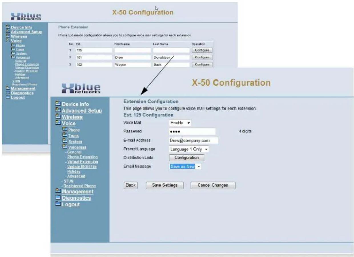
text_image
X-50 Configuration Device Info Advanced Setup Wireless Voice Phone Tools Trunk System Voicemail General Phone Extension Virtual Extension Update MOH File Holiday Advanced STUN Registered Phone Management Diagnostics Logout Phone Extension Phone Extension configuration allows you to configure voice mail settings for each extension. No. Est First Name Last Name Operation 1 125 Configura 2 101 Drew Donaldson Configura 3 102 Wayne Buck Configura X-50 Configuration Device Info Advanced Setup Wireless Voice Phone Tools Trunk System Voicemail General Phone Extension Virtual Extension Update MOH File Holiday Advanced STUN Registered Phone Management Diagnostics Logout Extension Configuration This page allows you to configure voice mail settings for each extension. Ext. 125 Configuration Voice Mail Enable Password ••••• 4 digits E-mail Address Drew@company.com Prompt Language Language 1 Only Distribution Lists Configuration Email Message Save as New Back Save Settings Cancel Changes- Voicemail - Enable/Disable - Disable the voice mailbox for any extension that should not have a voice mailbox.
- Password (4 Digit) - At default the voice mailbox password is set to 0000, and can be change to any 4 digit (0000 - 9999) number.
- E-mail Address - Enter the E-mail address for the user of this extension. SMTP Settings in "General Settings" must be programmed, or this will not work.
- Prompt Language - Select the language prompts to be used with this user.
Distribution Lists
Each extension has the ability to create three private distribution list, each with up to 10 members. This will allow the extension user to send a single voicemail message to multiple extension users at one time.
Distribution Lists
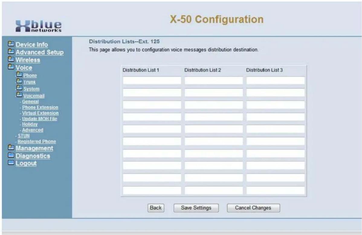
text_image
X-50 Configuration Device Info Advanced Setup Wireless Voice Phone Trunk System Voicemail - General - Phone Extension - Virtual Extension - Update MOH File - Holiday - Advanced - STUN - Registered Phone Management Diagnostics Logout Distribution Lists--Ext. 125 This page allows you to configuration voice messages distribution destination. Distribution List 1 Distribution List 2 Distribution List 3 Back Save Settings Cancel Changes- Enter the desired extension number into one or more distribution lists.
Virtual Extension
The X-50 system can have up to 50 virtual or phantom extensions, which are users that do not have a physical telephone, but want to have a mailbox on the system. Once a virtual number is assigned it can be used as an answer position, DID Routing position, and the callers will be sent directly to the mailbox. In addition, each virtual number can be programmed to receive an e-mail each time a new message is received.

text_image
X-50 Configuration Virtual Extension Virtual Extension configuration allows you to configure voice mail settings for each virtual extension. No Ext First Name Last Name Operation 1 831 Ronny Gordon Configure Device Info Advanced Setup Wireless Voice Phone Trunk System Vocemail General Phone Extension Virtual Extension Update MOH File Holiday Advanced STUN Registered Phone Management Diagnostics Logout X-50 Configuration Device Info Advanced Setup Wireless Voice Phone Trunk System Vocemail General Phone Extension Virtual Extension Update MOH File Holiday Advanced STUN Registered Phone Management Diagnostics Logout Extension Configuration This page allows you to configure voice mail settings for each extension. Ext. 830 Configuration Voice Mail Enable Password ••••• 4 digits E-mail Address rgordon@yourcompnay.cc Prompt Language Language 1 Only Distribution Lists Configuration Email Message Delete Leaving Messages Enable Back Save Settings Cancel Changes- Enter the virtual extension number - must be within the numbering plan - and press save.
- Once the virutal extension is saved, the "Configure" button will be come visible.
- Click on "Configure" to program voice mail message enable, password, e-mail delivery, language, Distribution list, email message, and leaving messages.
Update MOH File
Click on Browse to select a different Music on Hold file to play to callers on hold.
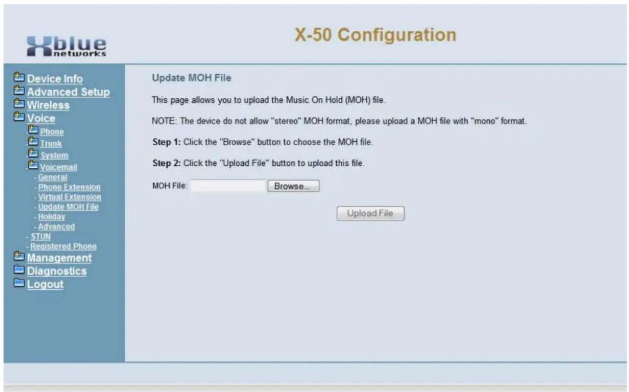
text_image
X-50 Configuration Device Info Advanced Setup Wireless Voice Phone Trunk System Voicemail - General - Phone Extension - Virtual Extension - Update MOH File - Holiday - Advanced - STUN - Registered Phone Management Diagnostics Logout Update MOH File This page allows you to upload the Music On Hold (MOH) file. NOTE: The device do not allow "stereo" MOH format, please upload a MOH file with "mono" format. Step 1: Click the "Browse" button to choose the MOH file. Step 2: Click the "Upload File" button to upload this file. MOH File: Browse... Upload FileHoliday Settings
This allows the administrator to preprogram up to 20 different dates to play a special holiday greeting. The holiday greeting will only play when the date matches the entry, after that date, the appropriate Day or Night greeting will begin playing automatically.
Holiday Settings Schedule
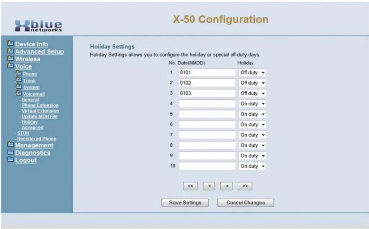
text_image
X-50 Configuration Device Info Advanced Setup Wireless Voice Phone Trunk System Voicemail - General - Phone Extension - Virtual Extension - Update MOH File - Holiday - Advanced - STUN - Registered Phone Management Diagnostics Logout Holiday Settings Holiday Settings allows you to configure the holiday or special off-duty days. No. Date(MMDD) Holiday 1 0101 Off duty ▼ 2 0102 Off duty ▼ 3 0103 Off duty ▼ 4 On duty ▼ 5 On duty ▼ 6 On duty ▼ 7 On duty ▼ 8 On duty ▼ 9 On duty ▼ 10 On duty ▼ << < > >> Save Settings Cancel Changes- Enter the month (MM) and day (DD) for each holiday. Enter each day that is considered a holiday separately. If the holiday lasts for two or more days enter each day individually. For example, if January 1, 2 and 3 were all holidays, each day will be entered individually.
- On/Off duty - Select on duty if the system should process the entered date or off duty to ignore the entry.
Advanced
Opens the X-50 FTP site to view the voicemail files

text_image
X-50 Configuration Device Info Advanced Setup Wireless Voice Phone Trunk System Voicemail - General - Phone Extension - Virtual Extension - Update MOH File - Holiday - Advanced - STUN - Registered Phone Management Diagnostics Logout Voice Mail advance setting allows you to browse, upload or download voice files through ftp server. Browse Voicemail FileClick on "Browse Voicemail File" to view the files.

WARNING - Any changes made in this page may result in erratic operation. DO NOT make changes unless instructed to do so by a qualified technical support representative.
STUN
Use STUN (Session Traversal Utilities for NAT) to support remote phones that are installed behind NAT or a firewall.
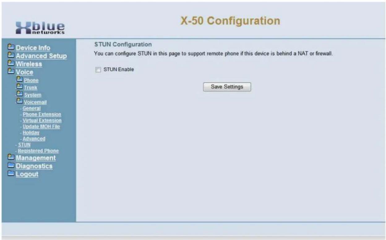
text_image
X-50 Configuration Device Info Advanced Setup Wireless Voice Phone Trunk System Voicemail - General - Phone Extension - Virtual Extension - Update MOH File - Holiday - Advanced - STUN - Registered Phone Management Diagnostics Logout STUN Configuration You can configure STUN in this page to support remote phone if this device is behind a NAT or firewall. □ STUN Enable Save SettingsRegistered Phones
Select registered phones to see which phones are currently connected to the system.
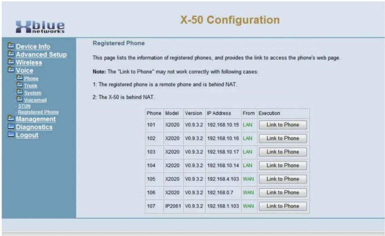
text_image
X-50 Configuration Device Info Advanced Setup Wireless Voice Phone Trunk System Voicemail -STUN -Registered Phone Management Diagnostics Logout Registered Phone This page lists the information of registered phones, and provides the link to access the phone's web page. Note: The "Link to Phone" may not work correctly with following cases: 1: The registered phone is a remote phone and is behind NAT. 2: The X-50 is behind NAT. Phone Model Version IP Address From Execution 101 X2020 V0.9.3.2 192.168.10.15 LAN Link to Phone 102 X2020 V0.9.3.2 192.168.10.16 LAN Link to Phone 103 X2020 V0.9.3.2 192.168.10.17 LAN Link to Phone 104 X2020 V0.9.3.2 192.168.10.14 LAN Link to Phone 105 X2020 V0.9.3.2 192.168.4.103 WAN Link to Phone 106 X2020 V0.9.3.2 192.168.0.7 WAN Link to Phone 107 IP2061 V0.9.3.2 192.168.1.103 WAN Link to Phone- Click on "Link to Phone" to make any adjustments to an individual telephone.
Note:
The "Link to Phone" feature was designed for connection within the same subnet and may not work when connecting through a firewall or NAT or WAN port.
Voice
Notes:
10 Management
Management
The Management Section of the system allows the administrator to perform special management functions.
- Device Info
- Advanced Setup
- Wireless
- Mobile Network
- Voice
-
Management
-
- Settings
- System Log
- TR-069 Client
• + Time Settings -
- Access Control
- PTC
- Update Software
- Reboot
- Diagnostics
- Logout
Settings
- Device Info
- Advanced Setup
- Wireless
- Mobile Network
- Voice
- Management
-
- Settings
- Backup
- Update
- Restore Default
- System Log
- TR-069 Client
• + Time Settings -
- Access Control
- PTC
- Update Software
- Reboot
- Diagnostics
- Logout
Settings
The settings area allows the administrator to create a backup, update the system, and restore the system to factory default.
Backup
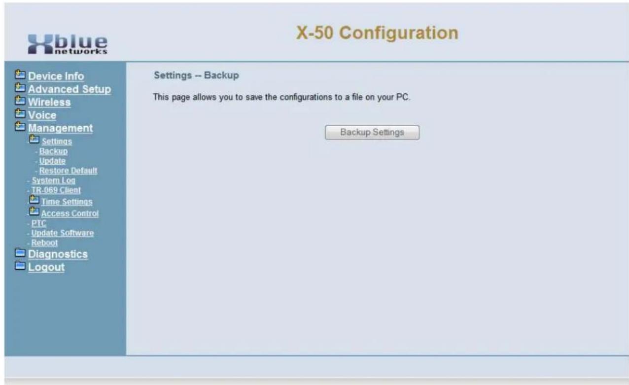
text_image
X-50 Configuration Device Info Advanced Setup Wireless Voice Management Settings -- Backup This page allows you to save the configurations to a file on your PC. Backup Settings - Backup - Update - Restore Default - System Log - TR-069 Client Time Settings Access Control - PTC - Update Software - Reboot Diagnostics LogoutClick on the "Backup Settings" button to create a back up of the system.
Update

text_image
X-50 Configuration Device Info Advanced Setup Wireless Voice Management Settings - Backup - Update - Restore Default - System Log - TR-069 Client Time Settings Access Control - PTC - Update Software - Reboot Diagnostics Logout Tools -- Update Settings This page allows you to update the configurations using the saved setting file. Step 1: Click the "Browse" button to choose the saved setting file. Step 2: Click the "Update Settings" button to update device to the saved configurations. Settings file: Browse... Update SettingsUse Update to restore a previously back up.
- Click on the Browse button and select the file to be used
- Click on Update Settings
Note:
The system will reboot, which will take about 2 minutes after the backup is restored.
Restore Default
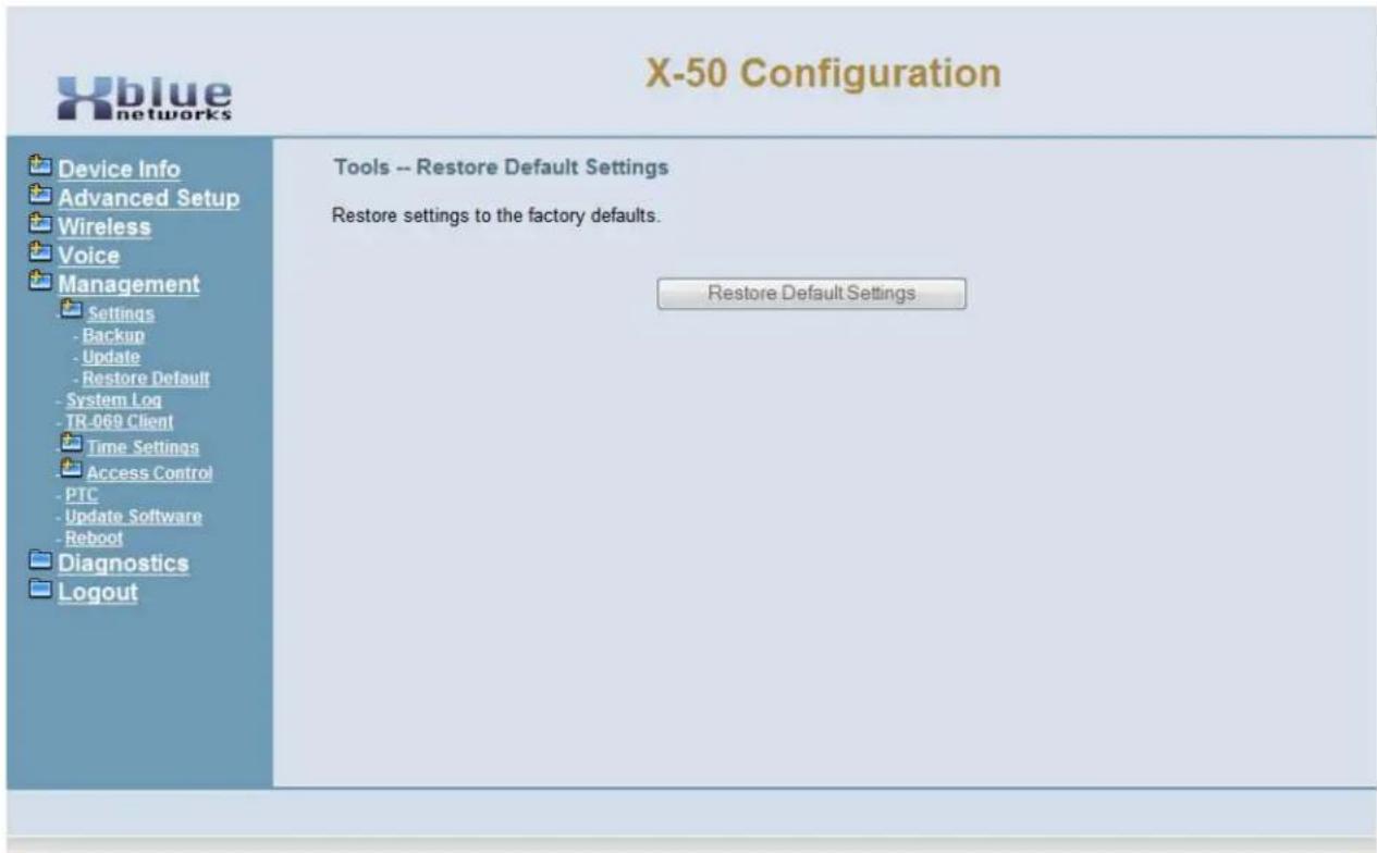
text_image
X-50 Configuration Device Info Advanced Setup Wireless Voice Management Settings - Backup - Update - Restore Default - System Log - TR-069 Client Time Settings Access Control - PTC - Update Software - Reboot Diagnostics Logout Tools -- Restore Default Settings Restore settings to the factory defaults. Restore Default SettingsUse the "Restore Default Settings" to return the system back to factory default. All programmed parameters will be restored to the factory default settings and "Initial Startup Wizard" will be activated.
System Log
The system log is used to verify and diagnose network settings and errors. There are several different levels of system logs, from informational to critical.

text_image
X-50 Configuration Device Info Advanced Setup Wireless Voice Management Settings Exchange Tools Database Default System Log X-50 Configur System Log The System Log doing allows you to use the System Log and configure the System Log options. Click "View System Log" to view the Syst. Click "Configure System Log" to configure the System Log options. View System Log Configure System Log X-50 Configuration Device Info Advanced Setup Wireless Voice Management Settings System Log TL-062 Client Time Settings Access Control PTC Update Software Reboot Diagnostics Logout System Log - Configuration If the log mode is enabled, the system will begin to log all the selected events. For the Log Level, all events above or equal to the selected level will be logged. For the Display Level, all logged events above or equal to the selected level will be displayed. If the selected mode is 'Remote' or 'Both,' events will be sent to the specified IP address and UDP port of the remote syslog server. If the selected mode is 'Local' or 'Both,' events will be recorded in the local memory. Select the desired values and click 'Apply/Save' to configure the system log options. Log: Disable Enable Log Level: Debugging Display Level: Informational Mode: Local Back Apply/SaveSelect "Configure System" log to select the level of logging required.
- Enable or Disable the Log
- Log Level - Select between Emergency, Alert, Critical, Error, Warning, Notice, Informational or Debugging. Each selection in the list, in descending order, adds more information to the log. Select the level of information that is needed.
text_image
Emergency Emergency Alert Critical Error Warning Notice Informational Debugging- Display Warning - Select between Emergency, Alert, Critical, Error, Warning, Notice, Informational or Debugging. Each selection in the list, in descending order, adds more information to the log. Select the level of information that is needed.
text_image
Emergency Emergency Alert Critical Error Warning Notice Informational Debugging- Mode - Local or Remote - Local mode is used to debug the system that the administrator is currently logged into. Remote mode is used to debug any system within the voice network.
TR-069
TR-069 is the protocol for Wide Area Networks (WAN) Management which defines the auto configuration of a server.
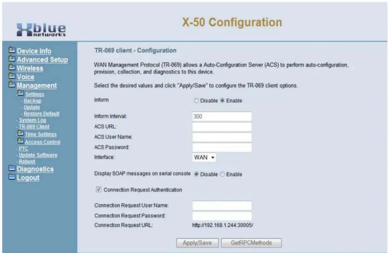
text_image
X-50 Configuration Device Info Advanced Setup Wireless Voice Management Settings - Backup - Update - Restore Default - System Log - TR-069 Client Time Settings Access Control - PTC - Update Software - Reboot Diagnostics Logout TR-069 client - Configuration WAN Management Protocol (TR-069) allows a Auto-Configuration Server (ACS) to perform auto-configuration, provision, collection, and diagnostics to this device. Select the desired values and click "Apply/Save" to configure the TR-069 client options. Inform Disable Enable Inform Interval: 300 ACS URL: ACS User Name: ACS Password: Interface: WAN ▼ Display SOAP messages on serial console Disable Enable ✓ Connection Request Authentication Connection Request User Name: Connection Request Password: Connection Request URL: http://192.168.1.244:30005/ Apply/Save GetRPCMethods- Device Info
- Advanced Setup
- Wireless
- Mobile Network
- Voice
- Management
-
- Settings
- Backup
- Update
- Restore Default
- System Log
- TR-069 Client
• + Time Settings
- Internet Time
- Daylight Saving time
-
- Access Control
- PTC
- Update Software
- Reboot
- Diagnostics
- Logout
These settings may have been changed during the Setup Wizard
Time Settings
The X-50 system has the ability to synchronize the date and time with up to five different time servers, and it can be set to use automatic daylight savings time rules.
Internet Time
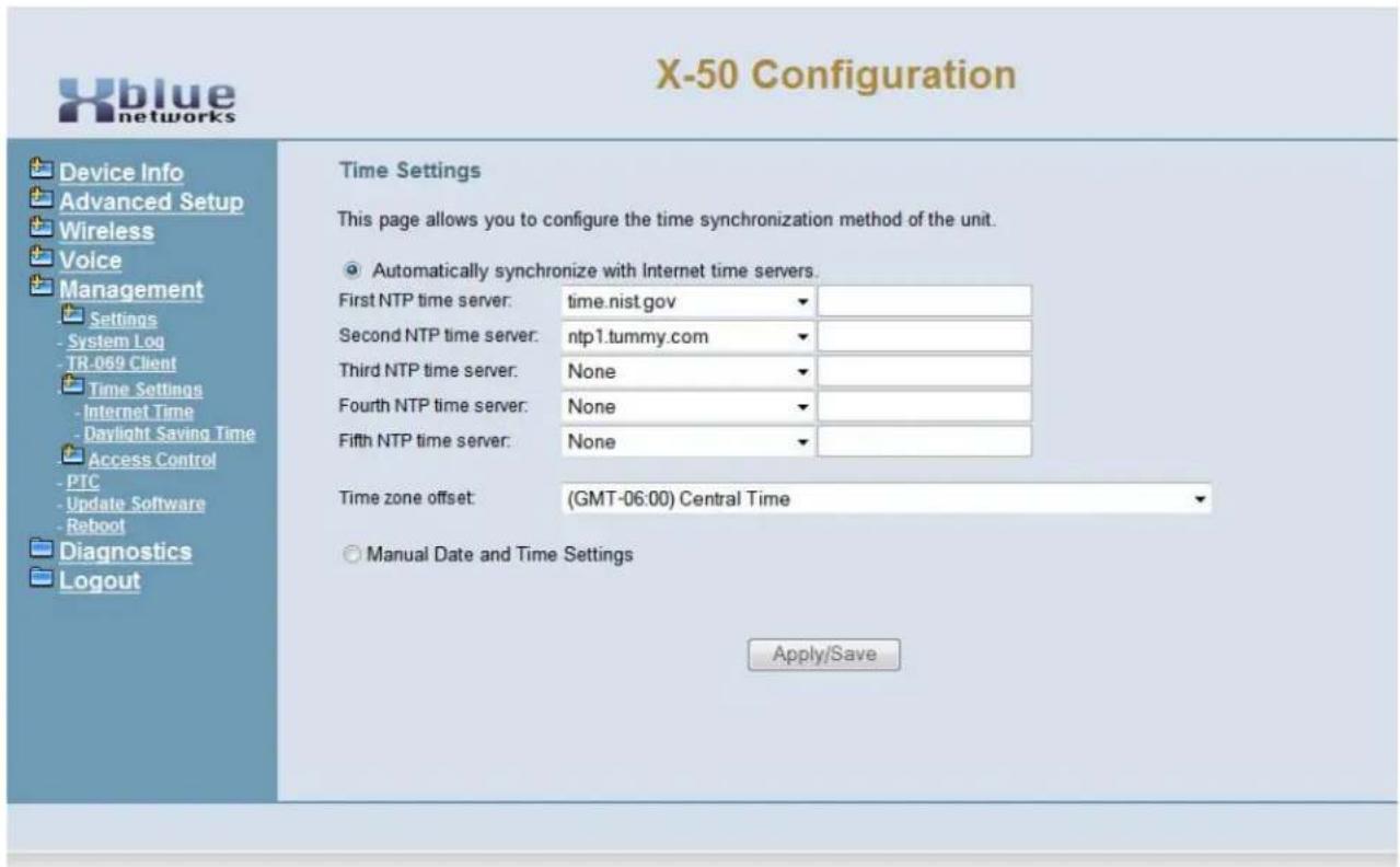
text_image
X-50 Configuration Device Info Advanced Setup Wireless Voice Management Settings System Log TR-069 Client Time Settings Internet Time Daylight Saving Time Access Control PTC Update Software Reboot Diagnostics Logout Time Settings This page allows you to configure the time synchronization method of the unit. Automatically synchronize with Internet time servers. First NTP time server: time.nist.gov Second NTP time server: ntp1.tummy.com Third NTP time server: None Fourth NTP time server: None Fifth NTP time server: None Time zone offset: (GMT-06:00) Central Time Manual Date and Time Settings Apply/Save- First (second, thrid, forth, fifth) NTP time serve. Only if the current server is unavailable will the next one be referenced.
- Time Zone Offset - Select the Time Zone where the system is installed.
Select Manual Date and Time Settings when not connected to a Network.
Manual Date and Time Settings
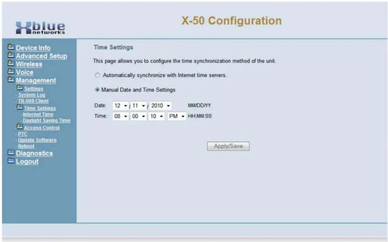
text_image
X-50 Configuration Device Info Advanced Setup Wireless Voice Management Settings - System Log - TR-069 Client Time Settings - Internet Time - Daylight Saving Time Access Control - PTC - Update Software - Reboot Diagnostics Logout Time Settings This page allows you to configure the time synchronization method of the unit. Automatically synchronize with Internet time servers. Manual Date and Time Settings Date: 12 / 11 / 2010 MM/DD/YY Time: 08 : 00 : 10 PM HH:MM:SS Apply/SaveDaylight Saving Time
The X-50 system can be set to use automatic daylight savings or it can be set to manual.
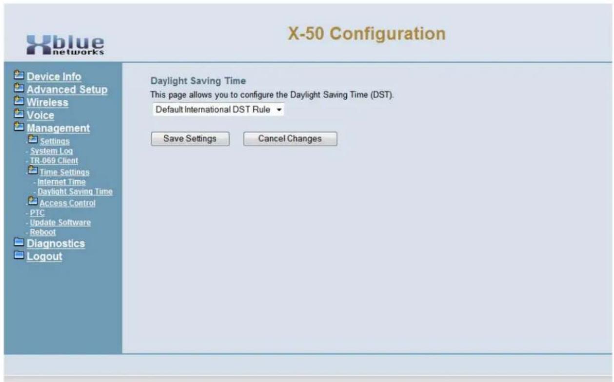
text_image
X-50 Configuration Daylight Saving Time This page allows you to configure the Daylight Saving Time (DST). Default International DST Rule Save Settings Cancel Changes Device Info Advanced Setup Wireless Voice Management Settings System Log TR-069 Client Time Settings Internet Time Daylight Saving Time Access Control PTC Update Software Reboot Diagnostics Logout- Device Info
- Advanced Setup
- Wireless
- Mobile Network
- Voice
-
Management
-
- Settings
- System Log
- TR-069 Client
• + Time Settings -
- Access Control
- PTC
- Update Software
- Reboot
- Diagnostics
- Logout
Access Control
Access control is used to control access to the gateway.
Web Port
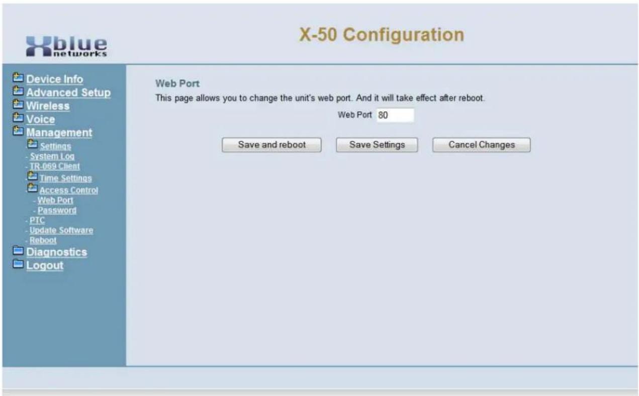
text_image
X-50 Configuration Device Info Advanced Setup Wireless Voice Management Settings - System Log - TR-059 Client Time Settings Access Control - Web Port - Password - PTC - Update Software - Reboot Diagnostics Logout Web Port This page allows you to change the unit's web port. And it will take effect after reboot. Web Port 80 Save and reboot Save Settings Cancel Changes- Select the port to be used when accessing the Web Port. At default it is set to port 80.
Note:
Changing this port may affect the operation of the system
Passwords
The X-50 has three different levels of passwords, Admin, Support and User.
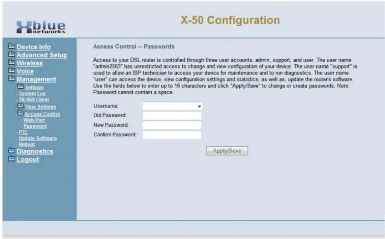
text_image
X-50 Configuration Device Info Advanced Setup Wireless Voice Management Settings - System Log - TR-069 Client Time Settings Access Control - Web Port - Password - PTC - Update Software - Reboot Diagnostics Logout Access Control -- Passwords Access to your DSL router is controlled through three user accounts: admin, support, and user. The user name "admin2583" has unrestricted access to change and view configuration of your device. The user name "support" is used to allow an ISP technician to access your device for maintenance and to run diagnostics. The user name "user" can access the device, view configuration settings and statistics, as well as, update the router's software. Use the fields below to enter up to 16 characters and click "Apply/Save" to change or create passwords. Note: Password cannot contain a space. Username: Old Password: New Password: Confirm Password: Apply/SaveTABLE 10.1 Passwords
| User Name Password Interface Access | ||
| admin2583 000000 LAN/WAN Full - Admin Programming | ||
| user user WAN Only Limited - System Admin | ||
| support support WAN Only Full - Technical Support | ||
PTC Configuration
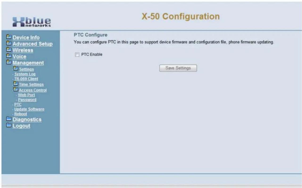
text_image
X-50 Configuration Device Info Advanced Setup Wireless Voice Management Settings System Log TR-069 Client Time Settings Access Control Web Port Password PTC Update Software Reboot Diagnostics Logout PTC Configure You can configure PTC in this page to support device firmware and configuration file, phone firmware updating. PTC Enable Save SettingsUpdate Software
Select update software to update the software on the X-50 VoIP Telephone System.
Note:
For best results the upgrade file must be stored on a local PC Hard drive. The upgrade procedure should only be done through the LAN port, Do no attempt this through the WAN port.
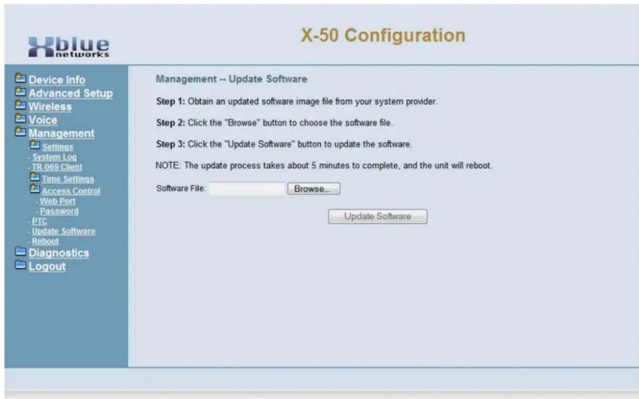
text_image
X-50 Configuration Device Info Advanced Setup Wireless Voice Management Settings - System Log - TR-069 Client Time Settings Access Control - Web Port - Password - PTC - Update Software - Reboot Diagnostics Logout Management -- Update Software Step 1: Obtain an updated software image file from your system provider. Step 2: Click the "Browse" button to choose the software file. Step 3: Click the "Update Software" button to update the software. NOTE: The update process takes about 5 minutes to complete, and the unit will reboot. Software File: Browse... Update SoftwareReboot
Use the Reboot page to reboot the gateway. Once the gateway begins, it will take about 2 minutes to complete the reboot process. If the software was upgraded, the reboot may take longer.
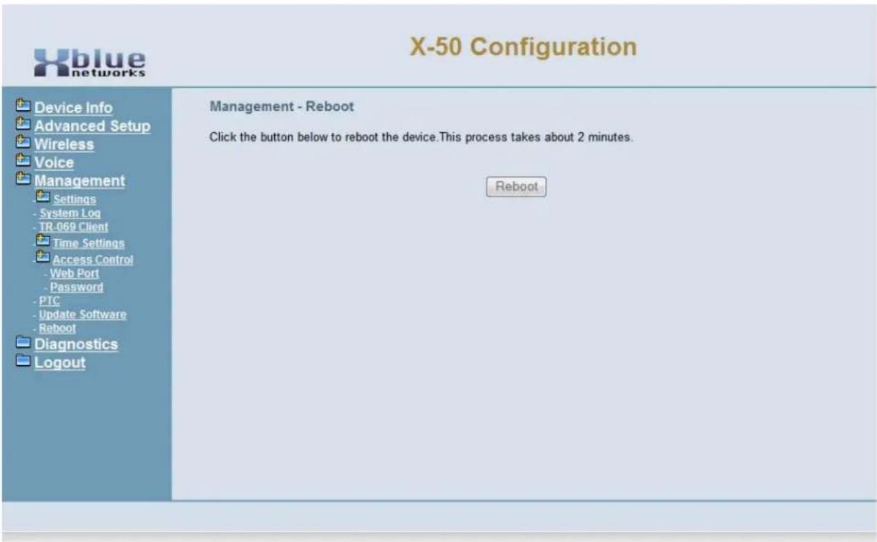
text_image
X-50 Configuration Device Info Advanced Setup Wireless Voice Management Settings System Log TR-069 Client Time Settings Access Control Web Port Password PTC Update Software Reboot Diagnostics Logout Management - Reboot Click the button below to reboot the device. This process takes about 2 minutes. Reboot11 Diagnostics
System Diagnostics
The Diagnostics page gives a snapshot of what is going on in the system, which is divided into four sections; "Test your network Connection", "Test the status of the PSTN Line", "Test the status of IP Trunk Line", "Test the status of Auto Attendant (AA) Line" and "Test the status of the FXS".
- Device Info
- Advanced Setup
- Wireless
- Mobile Network
- Voice
- Diagnostics
- Logout
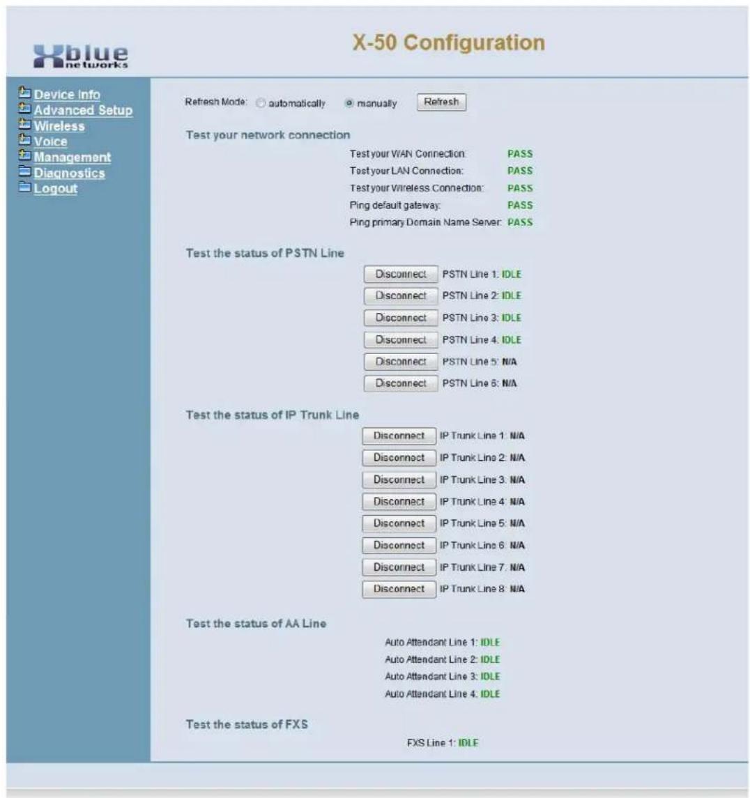
text_image
X-50 Configuration Refresh Mode: ○ automatically ● manually Refresh Test your network connection Test your WAN Connection: PASS Test your LAN Connection: PASS Test your Wireless Connection: PASS Ping default gateway: PASS Ping primary Domain Name Server: PASS Test the status of PSTN Line Disconnect PSTN Line 1: IDLE Disconnect PSTN Line 2: IDLE Disconnect PSTN Line 3: IDLE Disconnect PSTN Line 4: IDLE Disconnect PSTN Line 5: N/A Disconnect PSTN Line 6: N/A Test the status of IP Trunk Line Disconnect IP Trunk Line 1: N/A Disconnect IP Trunk Line 2: N/A Disconnect IP Trunk Line 3: N/A Disconnect IP Trunk Line 4: N/A Disconnect IP Trunk Line 5: N/A Disconnect IP Trunk Line 6: N/A Disconnect IP Trunk Line 7: N/A Disconnect IP Trunk Line 8: N/A Test the status of AA Line Auto Attendant Line 1: IDLE Auto Attendant Line 2: IDLE Auto Attendant Line 3: IDLE Auto Attendant Line 4: IDLE Test the status of FXS FXS Line 1: IDLEThe Diagnostic Page shows the status of the X-50 system. "Pass" indicates that the system is connected and operating correctly. "Failed" indicates that the network is not connected.
PSTN Line, IP Trunkk Line, Auto Attendant line, or FXS line will show when they are "Idle" or "Busy". If needed, press the "Disconnect" button to release the line.
12 Voicemail
Getting to Know your Voice Mailbox
A complete Voicemail and Auto Attendant come standard with the X-50 VoIP Telephone System. When the X2020 telephone is connected to an X-50 VoIP Telephone System, it can access voicemail by pressing the message button, which the button with an envelope.
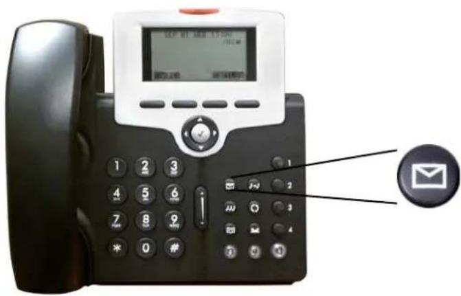
text_image
SEP 01 SEP 15:00 12:00 20:00 24:00 1 2 3 4 5 6 7 8 9 * 0 # 2-2 3 4 5 6 7 8 9 10 11 12 EmailWhen a new message arrives, the light above the display will begin flashing and the display will show an envelope with the new message count.
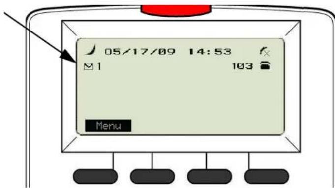
text_image
05/17/09 14:53 1 103 MenuSetting up your Voice Mailbox
It is a good idea to customize your voice mailbox when you being working with your new telephone system. To do this you will press your message button 📋 and you will be prompted to enter your password. The default password is four zeros (0000).
The voicemail system will prompt you, but you may dial the digit you wish when it answers. Use the following steps to personalize your greeting and name.
- Dial 3
- Press 2 - to record a new greeting
- Record your personalize greeting and then press the # key. A common greeting will be "Hi, this is Jonathan I am either on my phone or away from my desk. Please leave a detailed message and I will return your call as soon as I can."
- The message is automatically saved.
- Press # to go back one level
- Press 5 to record your name - Say only your first and last name and then press the # key.
- Simply hang up the phone and your voicemail is setup and active.
It is also a good idea to change the mailbox password. At default, the password is four zeros (0000) and can be changed to any 4 digit sequence from 0000 - 9999.
• After recording your personal greeting and Name...
- Press 4 to change the mailbox password.
- Enter the new four digit password
- Press 1 to confirm the new telephone number
Using your Voice Mailbox
Press the message button and enter the default or new password...
- Press 1 - To listen to new voicemail messages
- Press 1 - To listen to new messages
• Press 1 - To Save new messages
• Press 4 - To Delete the playing message
• Press 2 - To Skip to the next message
• Press 3 - To delete the playing message - Press 4 - To forward the message another mailbox
- Press 5 - To listen to the previous Message
- Press # - To go to the previous message
- Press 2 - Delete all Voice Mail Messages (New and Saved)
- Press 3 - Record your personal greeting
- Press 4 - Change your mailbox password
- Press 5 - Record your mailbox name
- Press 6 - Send a voicemail message to another extension
Remote Message Pickup
Messages, new and saved, may be picked up from a remote location. Call into the system and when the Auto Attendant answers....
- Press *
- Dial the mailbox number
- Enter your password
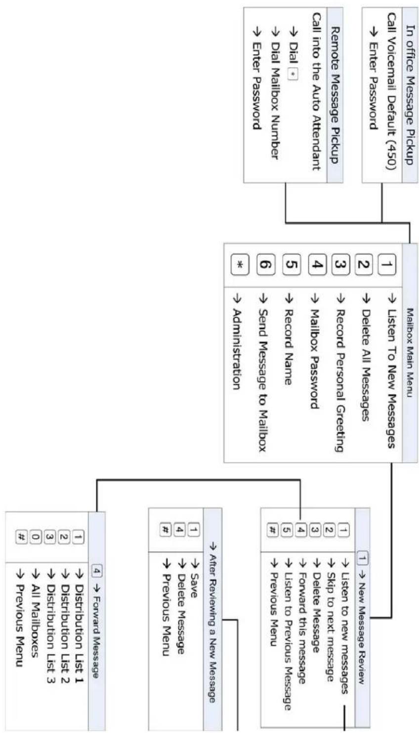
flowchart
graph TD
    A["In office Message Pickup"] --> B["Call Viocemail Default (450) → Enter Password"]
    B --> C["Cell into the Auto Attendant → Dial * → Record Name"]
    C --> D["6 → Send Message to Mailbox * → Administration"]
    D --> E["3 → Record Personal Creating"]
    E --> F["4 → Mailbox Password"]
    F --> G["5 → Record Name"]
    G --> H["6 → Send Message to Mailbox *"]
    H --> I["1 → Listen to New Messages"]
    I --> J["7 → New Message Review"]
    J --> K["After Reviewing a New Message"]
    K --> L["1 → Save #"]
    L --> M["2 → Distribution List 2"]
    M --> N["3 → Distribution List 3"]
    N --> O["# → All Mailboxes #"]
    O --> P["4 → Forward Message"]
    P --> Q["1 → Distribution List 1"]
K-50 Voicemail User Flow Chart
Voicemail Administration
Any mailbox can log into the administration mailbox to rerecord the main system greetings. The Automated (Receptionist) Attendant can answer with one of eleven (11) menus, each with five different greetings, Day, Lunch, Night, Holiday and Temporary.
To log into the administration mailbox, first log into one of the existing mailboxes....
- Press *
- Enter the administration mailbox Password - The default is six zeros (000000)
- Dial Zero to change the greeting mode from Day to Night or Night to Day
• Dial 1 to record the English Greeting - Enter the Greeting (Menu) ID number - 0, which is the default for all telephone lines, additional menu numbers are 1 through 10.
• Dial 1 to record the Day Greeting
• Dial 2 to record the Night Greeting
• Dial 3 to record the Break (Lunch) Greeting
• Dial 4 to record the Holiday Greeting
• Dial 5 to record the Temporary Geeting
In the Answer Position the auto attendant can be set with a "Menu Tree". A menu tree allows callers to route their call by dialing the digits associated with their choice. Each Menu can have its own personalized greeting, explaining what the caller should dial to find their desired person.
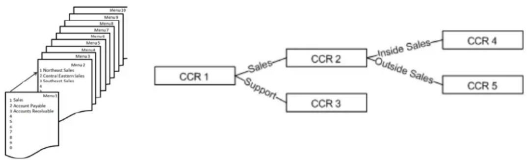
flowchart
graph TD
    A["Menu 1"] --> B["Menu 2"]
    B --> C["Menu 3"]
    C --> D["Menu 4"]
    D --> E["Menu 5"]
    E --> F["Menu 6"]
    F --> G["Menu 7"]
    G --> H["Menu 8"]
    H --> I["Menu 9"]
    I --> J["Menu 10"]
    K["1 Sales"] --> L["2 Account Payable"]
    L --> M["3 Accounts Receivable"]
    N["1 Northeast Sales"] --> O["2 Central Eastern Sales"]
    P["3 Southeast Sales"] --> Q["4"]
    R["4"] --> S["5"]
    T["6"] --> U["7"]
    V["8"] --> W["9"]
    X["0"] --> Y["10"]
    Z["Sales"] --> AA["CCR 1"]
    AB["Support"] --> AC["CCR 2"]
    AD["Inside Sales"] --> AE["CCR 4"]
    AF["Outside Sales"] --> AG["CCR 5"]
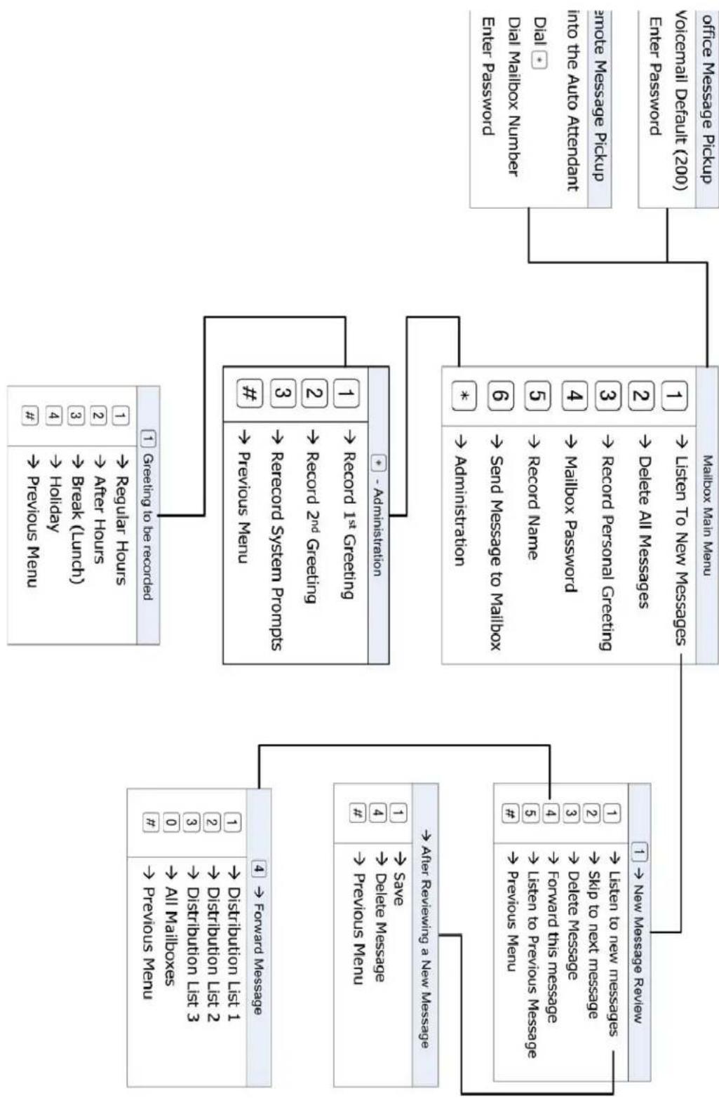
flowchart
graph TD
    A["mailbox Main Menu"] --> B["1 ← New Message Review"]
    A --> C["2 ← Delete All Messages"]
    A --> D["3 ← Record Personal Clearing"]
    A --> E["4 ← Mailbox Password"]
    A --> F["5 ← Record Name"]
    A --> G["6 ← Send Message to Mailbox"]
    A --> H["7 ← Administration"]
    A --> I["8 ← Record 1st Greening"]
    A --> J["9 ← Record 2nd Greening"]
    A --> K["10 ← Record System Prompts"]
    A --> L["11 ← Previous Menu"]
    A --> M["12 ← Record 3"]
    A --> N["13 ← Break (Launch)"]
    A --> O["14 → Holiday"]
    A --> P["15 ← After Hours"]
    A --> Q["16 ← Distribution List 1"]
    A --> R["17 ← Distribution List 2"]
    A --> S["18 ← Distribution List 3"]
    A --> T["19 ← Distribution List 4"]
    A --> U["20 ← All Mailboxes #"]
    A --> V["21 ← Forward Message"]
    A --> W["22 ← Prevouo Menu"]
    A --> X["23 ← Break (Launch)"]
    A --> Y["24 → After Hours #"]
    A --> Z["25 ← Beyond Menu #"]
    A --> AA["26 ← Record System Prompts #"]
    A --> AB["27 ← Record 1st Greening #"]
    A --> AC["28 ← Record 2nd Greening #"]
    A --> AD["29 ← Record System Prompts #"]
    A --> AE["30 ← Record 3rd Greening #"]
    A --> AF["31 ← Record 1st Greening #"]
    A --> AG["32 ← Record 2nd Greening #"]
    A --> AH["33 ← Record System Prompts #"]
    A --> AI["34 ← Record 3rd Greening #"]
    A --> AJ["35 ← Record 1st Greening #"]
    A --> AK["36 ← Record 2nd Greening #"]
    A --> AL["37 ← Record System Prompts #"]
    A --> AM["38 ← Record 3rd Greening #"]
    A --> AN["39 ← Record 1st Greening #"]
    A --> AO["40 ← Record 2nd Greening #"]
    A --> AP["41 ← Record 3rd Greening #"]
    A --> AQ["42 ← Record 1st Greening #"]
    A --> AR["43 ← Record 2nd Greening #"]
    A --> AS["44 ← Record System Prompts #"]
    A --> AT["45 ← Record 3rd Greening #"]
    A --> AU["46 ← Record 1st Greening #"]
    A --> AV["47 ← Record 2nd Greening #"]
    A --> AW["48 ← Record System Prompts #"]
    A --> AX["49 ← Record 3rd Greening #"]
    A --> AY["50 ← Record 1st Greening #"]
    A --> AZ["51 ← Record 2nd Greening #"]
    A --> BA["52 ← Record System Prompts #"]
    A --> BB["53 ← Record 3rd Greening #"]
    A --> BC["54 ← Record 1st Greening #"]
    A --> BD["55 ← Record 2nd Greening #"]
    A --> BE["56 ← Record System Prompts #"]
    A --> BF["57 ← Record 3rd Greening #"]
    A --> BG["58 ← Record 1st Greening #"]
    A --> BH["59 ← Record 2nd Greening #"]
    A --> BI["60 ← Record System Prompts #"]
    A --> BJ["61 ← Record 3rd Greening #"]
    A --> BK["62 ← Record 1st Greening #"]
    A --> BL["63 ← Record System Prompts #"]
    A --> BM["64 ← Record 2nd Greening #"]
    A --> BN["65 ← Record System Prompts #"]
    A --> BO["66 ← Record 1st Greening #"]
    A --> BP["67 ← Record System Prompts #"]
    A --> BQ["68 ← Record 2nd Greening #"]
    A --> BR["69 ← Record System Prompts #"]
    A --> BS["70 ← Record 3rd Greening #"]
    A --> BT["71 ← Record System Prompts #"]
    A --> BU["72 ← Record 1st Greening #"]
    A --> BV["73 ← Record System Prompts #"]
    A --> BW["74 ← Record 2nd Greening #"]
    A --> BX["75 ← Record System Prompts #"]
    A --> BY["76 ← Record 3rd Greening #"]
    A --> BZ["77 ← Record System Prompts #"]
    A --> CA["78 ← Record 1st Greening #"]
    A --> CB["79 ← Record System Prompts #"]
    A --> CC["80 ← Record 2nd Greening #"]
    A --> CD["81 ← Record System Prompts #"]
    A --> DD["82 ← Record 3rd Greening #"]
    A --> DE["83 ← Record System Prompts #"]
    A --> DF["84 ← Record 1st Greening #"]
    A --> DG["85 ← Record System Prompts #"]
    A --> DH["86 ← Record 2nd Greening #"]
    A --> DI["87 ← Record System Prompts #"]
    A --> DJ["88 ← Record 3rd Greening #"]
    A --> DK["89 ← Record System Prompts #"]
13 Glossary of Terms
Glossary
ARP – Address Resolution Protocol – allows devices to find a "host device" using the network layer (MAC Address). This allows SIP telephone endpoints to use non static IP Addresses when connecting to the system
ACLEP – Algebraic Code Excited Linear Predication – Reproduces voice transmissions using mathematical approximation that is determined 15ms prior to the next transmission, which itself is calculating at 10 frames per second. This approximation allows for greater voice compression and significantly better voice quality.
ATM – Asynchronous Transfer Mode – A packet switching transfer method designed to transport real time voice and video over a standard telephone line.
Bridge – A Cable or DSL modem/gateway is required to identify a specific location on their network. Some ISP units incorporate a router so that the user does not have to purchase another device, while others use a unit that has no routing capability, and requires the user to supply a router. When using remote workers or joining a voice network the ISP units must be set as a bridge, and the X-50 system is used at the router.
BSS - Basic Service Set -.
BSSID - Basic Service Set Identifier (BSSID) -
CHAP – Challenge Handshake Authentication Protocol – similar to PAP but the ID and password is encrypted.
CO - Central Office - A legacy telephone company line.
Converged - A converged PBX is a system that can be used with both VoIP and PCM/TDM. The converged system uses the PCM/TDM internally, while a Media Gateway (see Gateway) is used to integrate the Voice over IP component.
Default Gateway – The default gateway, usually seen as an IP Address, is the location used for endpoints to access the Internet, sometimes called the "Doorway to the Internet". If the default gateway is not entered or entered incorrectly, endpoints will have no access to the Internet.
Differentiated Services Code Point (DSCP) – The DSCP is part of the overall Quality of Service (QOS) strategy.
DMZ – In computer network security there is a special location commonly called the Demilitarized Zone but really stands for Data Management Zone, which can be a physical or logical subnetwork that is exposed to external services such as the Internet.
DNS – A Domain Name System is the “Phone Book” for the Internet. It translates “Human Relatable” names such as www.xbluenetworks.com into the numeric IP Address. The DNS can be a local or remote server, and it is a essential part of today’s Internet.
(DHCP) Dynamic Host Configuration Protocol – A dynamic IP address is assigned by a DHCP server, such as a router or network file server. Each time a network device is powered on it is “leased” (issued) an IP Address which has a scheduled expiration time. Once the lease expires the address may be released to the same device or another device.
FXO - Foreign Exchange Office - is where a standard telephone line is connected and requires telephone line signaling interface for standard analog telephone lines also known as "POTS", Plan Old Telephone Service. When the telephone line is taken off hook, the FXO signals the telephone line provider by closing the "loop relay", which signals the telephone line provider that it is off hook and should receive dial tone.
FXS - Foreign Exchange Station - is where a standard Analog or Single Line Telephone is connected to the system. The system provides talk battery, dial tone, generates ring voltage and generates DTMF Tones for the telephone line provider to process and make calls.
Gateway – A Gateway, sometimes called a Media Gateway, is the device that joins dispirit ne works; similar to a MUX, taking a T1 and converting it to a standard Loop-Start CO Line.
Gatekeeper – A Gatekeeper maintains a registry of remote devices. Each remote device must register and be authenticated to be granted access to the "Voice Network". In addition, it provides address translation and provides other services such as bandwidth management and locating gat ways.
H.323 - the originally created as a multi-media protocol, later to incorporate Voice over IP. It is the most mature and widely used protocol.
Intranet – An Intranet is a private computer network that an Internet Protocol backbone. This could be considered a private version of the Internet.
Internet – The Internet is a series of interconnected computers and computer networks that transmit and receives data using a packet switching protocol known as Internet Protocol. The Internet is generically known as the “World Wide Web”.
IGW – Internet Gateway – A gateway joins two or more disparate networks, such as an intranet (LAN) from the Internet (WAN), or when separating a normal LAN from wireless guests. Generally, a gateway will have at least one each WAN and LAN port.
IGMP – Internet Group Management Protocol – The protocol that manages multicast groups to more efficiently stream multicast groups, such as Video and Gaming.
IP Address – Internet Protocol Addresses – IP addresses are assigned two different ways, static or Dynamic.
Static - A static IP Address is used by any device that establishes infrastructure, such as a router, a severer, a printer, faxes etc. Internal or Intranet IP address are easy to establish and program. However, Internet static IP addresses are usually purchased at a premium but they are required when several endpoints are “pointed” to the same location such as a voice server.
Dynamic - A dynamic IP Address is used by any device that does not establish infrastructure, such as a client endpoint. A client endpoint (laptop for example) moves freely, so it is assigned a temporary IP Address from a device such as a server or router. These addresses are “leased” to the device for a period of time and are subject to change.
ISP – Internet Service Provider – An Internet Service Provider (ISP) is generally either a telephone or cable company which provides a high speed connection to the World Wide Web (www).
IETF – Internet Engineering Task Force – The task force wrote the specification SIP.
Jitter - defines the lack of synchronization caused by mechanical or electrical changes. The most common cause for jitter is lack of bandwidth.
LAN – Local Area Network – A LAN allows network devices to share and access files through a series of wires known as a "Network". Generally, a LAN uses one DHCP Server, it is "small" in size (geographically) like a home or office, and it does not require any external IPS to transmission data between endpoints.
Latency - is an important indicator of the dynamic performance of a Virtual Acoustic Environment (VAE). In a VAE, the end-to-end latency refers to the time elapsed from the beginning of an event or action, such as a voice transmission, until the receiving party hears the signal. High latency causes poor reproduction of a voice transmission, whereas lower latency results in higher voice quality.
LDAP – Lightweight Directory Access Protocol – A directory is a set of objects with similar attributes organized in a logical and hierarchical manner. The most common example is the telephone directory, which consists of a series of names (either of persons or organizations) organized alphabetically, with each name having an address and phone number attached.
MAC – Media Access Control– The MAC address is a unique, level 2, identifier which is required on all devices that connect to a network. This address is usually assigned at the factory where the device is built. Unlike an IP or Subnet Mask address, the MAC address does not change, which is critically important when using Dynamic Host Configuration Protocol (DHCP). A MAC address consists of 6 octets in hexadecimal format and looks like xx:xx:xx:xx:xx:xx (00-01-43-65-a0-e4).
Menu Trees - A menu tree is a series of choices that a caller can dial to process their call more efficiently. For example, a main greeting may instruct the caller to dial 1 for sales, which accesses menu 2, which instructs the caller to dial 1 for Northeast Sales, 2 for Central Eastern Sales, Southeast Sales, etc.
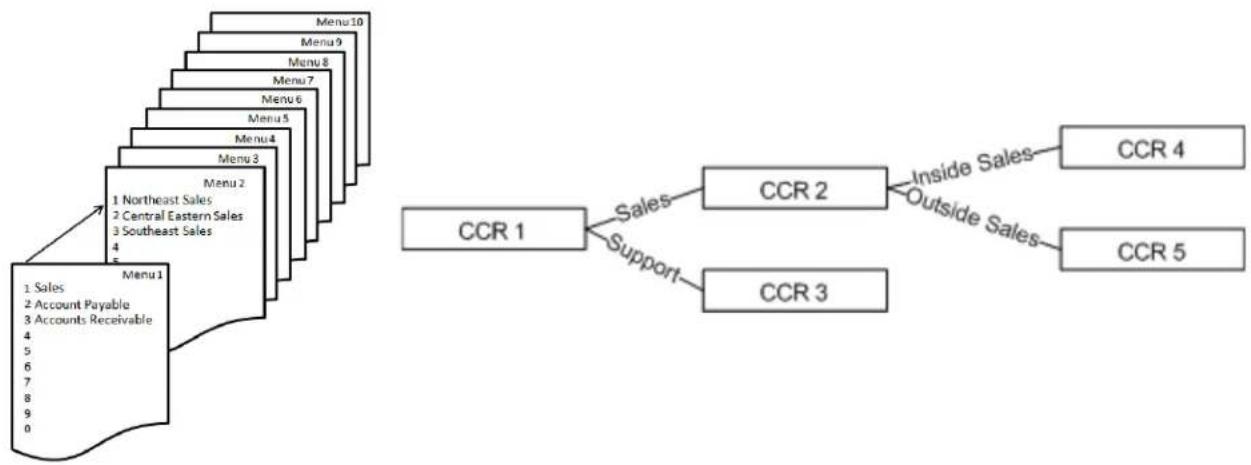
flowchart
graph TD
    A["Menu 1"] --> B["Menu 2"]
    B --> C["Menu 3"]
    C --> D["Menu 4"]
    D --> E["Menu 5"]
    E --> F["Menu 6"]
    F --> G["Menu 7"]
    G --> H["Menu 8"]
    H --> I["Menu 9"]
    I --> J["Menu 10"]
    K["1 Northeast Sales"] --> L["2 Central Eastern Sales"]
    L --> M["3 Southeast Sales"]
    M --> N["4"]
    O["1 Sales"] --> P["2 Account Payable"]
    P --> Q["3 Accounts Receivable"]
    R["CCR 1"] --> S["CCR 2"]
    S --> T["CCR 4"]
    S --> U["CCR 5"]
    V["Support"] --> W["CCR 3"]
    X["Inside Sales"] --> Y["CCR 4"]
    X --> Z["CCR 5"]
Enable Wireless Multicast Forwarding (WMF) - is a delivery protocol for information to a group of destinations. Although most applications use unicast (broadcasting to a single location), WMF is typically used in oneway streaming media. At default, this is disabled.
NAT – Network Address Translation – NAT reconciles the internal DHCP Addresses with the published Static IP Address. It is this protocol that makes it possible to share one published Internet address with multiple internal LAN devices.
NIC – Network Interface Card – Any device that connects to a network requires either a wired or wireless Network Interface Card. Each NIC has its own unique Media Access Control (MAC) address.
NPT – Network Time Protocol – A protocol that defines the ability to synchronize different computer systems over a packet switched network, using UDP packets via port 123 as the transport layer.
TABLE 13.1 Some Network Time Protocol
| Network Time Protocol | |
| time-a.nist.gov129.6.15.28NIST, Gaithersburg, Maryland | time.nist.gov192.43.244.18NCAR, Boulder, Colorado |
| time-b.nist.gov129.6.15.29NIST, Gaithersburg, Maryland | nist1.dc.certifiedtime.com216.200.93.8Abovnet, North Virginia |
| time-a.timefreq.bldrdoc.gov132.163.4.101NIST, Boulder, Colorado | nist1.dc.certifiedtime.com216.200.93.8Abovnet, North Virginia |
| time-b.timefreq.bldrdoc.gov132.163.4.102NIST, Boulder, Colorado | nist1.dc.certifiedtime.com216.200.93.8Abovnet, North Virginia |
| time-c.timefreq.bldrdoc.gov132.163.4.103NIST, Boulder, Colorado | nist1.nyc.certifiedtime.com208.184.49.129Abovnet, New York City |
| utcnist.colorado.edu128.138.140.44University of Colorado, Boulder | nist1.sjc.certifiedtime.com207.126.103.202Abovnet, San Jose, California |
P2P – Peer to Peer – All computers have the ability share information with each other without logging into a server. This protocol is very helpful with VoIP.
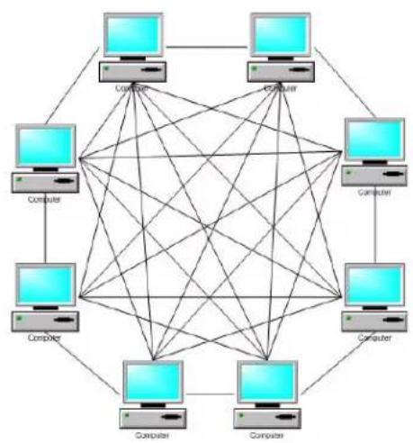
natural_image
Geometric network diagram with eight connected landfills (no text or symbols)PPPoE – Point-to-Point Protocol over Ethernet – This transport protocol is used on telephone networks as "ATM", where the DSL modem encapsulates PPP packets inside ATM cells and send them over a WAN Connection.
PAP – Password Authentication Protocol – This requires the requesting device to send an un-encrypted authentication, which must contain both the ID and password, to the local router when attempting to connect.
MSCHAPS – Microsoft Version Challenge Handshake Authentication Protocol – enables mutual authentication between peers by piggybacking a peer challenge and response packet for each successful packet.
Protocol - A clearly defined way of doing something.
PSTN – Public Service Telephone Network – Is the generic name given to the legacy telephone company lines.
QOS – Quality of Service – Although QoS is synonymous with packet prioritization; it really is the measurement of the voice or data transmission quality, from end to end. However, QoS can be improved by using packet prioritization, which allows voice to take precedents over data packets. This results in a better “connection” and communication between two end points.
Remote Worker – A remote worker is someone that will be using the telephone system's resources but does not reside in the same physical area.
RJ21X – An RJ21X is the location, usually on a “Punchdown Block”, where the Telephone Compnay’s Telephone Lines enter into the building.
Router – A router is used to direct incoming and outgoing data packets. A router is often used to assign DHCP Addresses, basic Internet security and Network Address Translation (NAT).
Security – (See Wireless Security)
SIP – Session Initiated Protocol – This protocol was specifically developed for transmitting voice over the Internet, by communications professionals. SIP has very little “overhead” helping to eliminate jitter and latency. Although not yet realized, SIP was developed as an “universal standard”, and the goal is to make SIP phones as common as standard 2500 sets.
STUN – Session Traversal Utilities for NAT – STUN is a protocol that allows applications operating through a Network Address Translation (NAT) to discover the presence of a network address translator and to obtain the mapped IP address and port number that the NAT application (UDP) contains to remote hosts.
SMTP – Simple Mail Transport Protocol – is the standard used to transport outgoing electronic mail (E-mail) across IP Networks. Generally, SMTP uses Port 25, but must sophisticated gateways will allow the administrator to match the port with the provider.
Static IP Address – See IP address
SSID – Service Set Identifier – is the name that identifies a particular wireless LAN. This name is broadcast and can easily be found by another wireless device.
SSL – Secure Sockets Layer – is one of the cryptographic protocols (type of encryption) used to provide security over an IP network such as the Internet. Generally, SSL uses port 443.
Subnet Mask Address – The Subnet Mask Address is used to segment (divide) a network into multiple networks. Also, using a complex mathematical formula, the Subnet Mask Address is used to determine how many IP Addresses are available per Class.
Basically, the lower the number, the more IP Addresses are available. For example, if the Subnet Mask Address is 255.255.255.0, only the last number is 0, so the maximum number of IP addresses possible is 254 (both zero 0 and 255 are reserved). If the Subnet Mask Address is 255.255.0.0 then the possible number of IP addresses becomes 255^2 or 66,000. Finally if the Subnet Mask Address is 255.0.0.0 then the possibilities are 255^3 or 16.8 million addresses. The Subnet Mask Address consists of a group of 4 numbers (Octets), each ranging from 0\~255, and is usually written as xxx.xxx.xxx.xxx.
| Subnet Mask Max Subnets Client Devices | ||
| 255.255.255.0 1 254 | ||
| 255.255.240.0 16 65,280 | ||
| 255.255.224.0 32 261,120 | ||
| 255.255.192.0 64 1,044,480 | ||
| 255.255.128.0 128 4,177,920 | ||
| 255.255.0.0 255 16,581,375 | ||
TDM - Time Division Multiplexing - The division of voice transmission, based on time.
URL- Uniform (Universal) Resource Locator - This is a subset, along with Uniform Resource Name, of Uniform Resource Identifier, which is used to retrieve websites using a name rather than an IP Address.
Vocoders – A voice encoder, known as a Vocoder, defines the voice compression and decompression that will be used for the voice transmission. Currently, all Voice over IP connections are full duplex, so every call opens bandwidth for “send, Receive, and Overhead (data signalling)”. Common Vocoders are G.711, G.728, G.729, G.723.1
VoIP – Voice over Internet Protocol – Voice over IP is a protocol that defines the transport of voice packets, using Internet Protocol, over a LAN, WAN or Internet.
VPN – A Virtual Private Network is a communications network “tunneled through” another ne work, creating a larger dedicated network. The “tunnel” is built using special security protocols, which are established and accepted by all parties. Once the “tunnel” is established the locations will continuously send a “keep alive” signal to keep the locations connected.
WAN – Wide Area Network – A WAN network devices to share and access files through a series of wires known as a “Network”. A WAN is used with multiple locations, and has no physical boundaries. It is actually possible to have a WAN that spans the globe.
Wireless Security –
- Open – no encryption – not recommended
- Shared – each device on the wireless network must use the same “Shared” authentication key. This should be considered rudimentary security.
- 802.1x – is a Port based authentication which generally requires a client application, which authenticates to a specified server (RADIUS) before being allowed to connect to the wireless access point.
- WEP – Wired Equivalent Privacy – One of the original wireless encryption protocols, which was thought to be secure. Today, with a minor investment, it can be cracked pretty quickly. This should be considered basic security.
- WPA – Wi-Fi Protected Access – an “intermediate measure” security protocol created by the Wi-Fi Alliance, which is found to be more secure than WEP.
- TKIP – Temporal Key Integrity Protocol – Was added to WPA and is backwards compatible with older WEP devices, but can be infiltrated with re-injection and spoofing.
- PSK – Pre-Shared Key (RFC 4785) – can be convenient when managing a closed network for easier authentication.
- WPA2 – The second version of WPA, which is more secure, but does not always work with older wireless installations.
- AES – Advanced Encryption Standard – Block Cipher encryption which was adopted by the US Government, and now used world wide for security.
- RADIUS – (RFC 2865) Remote Authentication Dial in User Service – is a client/server protocol using centralized authentication, which requires a network server for all endpoints that connect to the network. This is done in the application layer, using UDP packets.
- RADIUS Port – The “Well Known Ports” for sending UDP packets are 1812 and 1645 depending on the network installation and the server.
Well Known Ports - Personal Computers have approximately 64,000 "virtual" Ports, each can be used for specific tasks. For example, Port 80 is used to access the Internet, Port 25 is used for SMTP, etc. There are a group of these ports that are called "Commonly Open" or "Well Known Ports" and generally are between 0 and 1023. In table 9.2 there is a list of "Well Known Ports" and some Not so "Well Known Ports".
TABLE 13.2 Well Known Ports
| Port Number Description | |
| 21 FTP | |
| 23 Telnet | |
| 25 SMTP | |
| 53 Domain Name Server (DNS) | |
| 80 HTTP - Commonly known as the Internet | |
| 110 POP3 | |
| 119 Network News Transfer Protocol | |
| 125 NTP (Network Time Protocol) | |
| 143 IMAP | |
| 220 IMAP Version 3 | |
| 389 LDAP | |
| 443 HTTPS | |
| 531 AOL Instant Messenger (Unofficial) | |
| 636 LDAPS | |
| 953 DNS | |
| 992 Telnet over TLS/SSL | |
| 993 IMAPS | |
| 995 POP3 over TLS/SSL | |
| 1194 Open VPN | |
| 3101 Blackberry Enterprise Server (Unofficial) | |
| 3389 Microsoft Remote Server (Remote Desk Top) | |
| 5060 SIP | |
| 5061 SIP over TLS | |
| 5500 VNC remote Desktop Protocol (Unofficial) | |
| 5631 PC Anywhere (data) | |
| 5632 PC Anywhere (Status) | |
| 5800 VNC over HTTP (Unofficial) | |
| 5900 Virtual Network Computing (VNC) - Apple Remote Desktop | |
| 5938 Team Viewer Remote Desktop (Unofficial) | |
| 6891 - 6900 Windows Live Messenger - File Transfer (Unofficial) | |
| 6901 Windows Live ME messenger - Voice (Unofficial) | |
| 8008 HTTP Alternate | |
| 23399 Skype (Unofficial) | |
Wi-Fi Multimedia - WMM is the standard which was created to define QOS with WiFi Networks and is used to improve audio, video and Voice applications transmitted over WiFi.
WWW – World Wide Web – The world wide web is the generic name for the Internet.
Index
Numerics
802.11 89
802.11a 24, 145
802.11b 24, 89, 145
802.11g 24, 89, 145
802.11n 24, 89, 145
802.11n/EWC 159
A
Access Control 230
Web Port 230
Access Point PIN 153
ACLEP 243
Action When MAX Error Reached 203
Address Resolution Protocol 108, 243
Admin Password 203
Administration Control 128
Advanced 102
Advanced Network Address Translation (NAT) 116
Advanced Programming 110
AES 152, 250
Agent Log On/Off
UCD 53
Agent Log on/off 48
Algebraic Code Excited Linear Predication 243
All Paging Group 188
All Ring Group 180, 190
Alphanumeric Display 48, 53
Analog Telephone Trunks 172
Answer Position 179
All Ring Group 180
Auto Attendant 179
Extension 179
ICD
All Ring 180
Linear 180
ICD Group 180
Line Selection 179
Operator 180
ARP 108, 243
Assured Forwarding Classes 134
Asynchronous Transfer Mode 243
ATM 243, 247
Auto Attendant 16, 202, 235, 237
Email Header 206
Voicemail Tag 206
Automated Receptionist 202
Automatic Authentication Protocol 113
Automatic Channel Timer 159
Automatic Configuration 110
Automatic Daylight Savings 228
Automatic Hold 48, 54
Automatic Power Save Delivery 160
B
Backlit Display 53
Backup 219
Bandwidth 19, 159
Bandwidth Control 135
Basic Service Set 89, 243
Basic Service Set Identifier 89, 147, 149, 243
BSS 89, 243
BSSID 89, 147, 149, 243
Busy Callback 48, 54
C
Call Abandon Time 195
Call Block 50
Call Blocking 61
Call Fork 55
Call Forking 48
Call Forward 55
Busy 48
Direct 48
DND 49
External 50
Follow Me 49
No Answer 49
Remote 50
Call Hold 50, 59
Call Log 50, 59
Call Park 50, 60
Call Park Answer 50
Call Park Number 191
Call Pickup 50, 60
Call Restriction Table 168
Call Routing 181
Delete 181
Destination 181
From 181
Insert 181
MAXLengh 181
MinLength 181
To 181
Call Routing Table 82, 97
Delete Digits 99
From 99
Max 99
Min 99
To 99
Call Waiting 50, 60
Caller ID Method 194
Callouts 13
Campus 15
Campus Environment 18, 25, 196
Category 3 79
Category 5 76, 79
Category 5E 76, 79
Category 6 76, 79
Central Office 243
Challenge Handshake Authentication 86, 113, 243
CHAP 86, 113, 243
MSCHAP 86
Cipher Encryption 152, 250
Class of Service 184
COS 167
Day 168
Night 168
Traveling 31, 51, 62
Class Selector 134
Clients Isolation 147, 149
CO Line 243
Common Voicemail Greeting 238
Conference - 3-Way 61
Conference 3-Way 51
Configure System 222
Connecting Multiple Systems 196
Converged 243
D
Data Management Zone 244
Date & Time 104
Day and Night
Alternate Operator 188
Operator 188
Day Operator 91, 93
Daylight Savings 228
Days for keeping Voice Mail 206
DDNS 139, 141
Default Gateway 82, 85, 243
Delay Ring Time 195
Demilitarized Zone 121, 244
Destination Network Address 137
Gateway IP Address 137
Subnet Mask 137
Device 108
Device Info 102
DHCP 83, 87, 88, 109, 115, 244
DHCP Address 248
DHCP Server, 80
Diagnostic
Busy 236
Disconnect 236
Failed 236
Idle 236
Pass 236
Diagnostics 102
Diagnostics Pages 235
Dial by Name Code 204
Dial Plan 91
Dial Wait Time 195
DID 171, 176
Destination 96
DID Number 176
Direct Inward Dial 82
Display Name 176
Outgoing Caller ID 96, 176
Ringing
Destination Number 176
Extension Number 176
Trunk Group 176
DID Number 96
Differentiated Services Code Point 133
Direct Inward Dial 171
Direct Inward Dial (DID) 176
Direct Inward System Access 204
DISA 204
Disable Voice Mailbox 208
Disable WMM Advertise 147, 149
Distinctive Ringing 51, 62
Distributed Group 190
DMZ 121, 244
DND
Display Name 96
DNS 85, 86, 111, 244
Do Not Disturb - DND 63
Do Not Disturb (DND) 51
Domain Name System 85, 86, 244
Standard 139
Domain Server 95, 174
Down Stream 87, 115
Downstream Bandwidth 135
DSCP 133, 134
DSL 247
DSP IP Address 115
DTMF Digit 206
DTMF Signal off Duration 195
DTMF Signal on Duration 195
DTMF Type 194
Dynamic DNS 139
Dynamic Domain Name System 139
Dynamic Host Configuration Protocol 83, 87, 88, 109, 110,
115, 244
Dynamic IP Address 141, 244, 245
Dynamic Name Service 111
DynDNS Settings 141
DynDNS.org 141
E
E-mail Delivery 206
E-mail Delivery of a Voice Message 202
E-mail Notify with Voice Files 206
Emergency Number Routing 185
Enable Label 178
Enable Wireless 89, 147, 148
Enable Wireless Multicast Forwarding 147, 149
Environmental 23
Ethernet Cable 79
Extensible Authentication Protocol 152
Extension
Extension Number 91
Ringing 179
Voice Mailbox 208
Voicemail 208
Extension Feature Reset 51, 63
External Call Forward 50
F
Factory Default 219, 221
FAX
Detection 194
Support 194
Feature (Flexible) Button 64
Feature Button Programming 51
Feature Button Reset 52, 66
File Server 143
Password 143
User Name 143
Firewall 83, 85, 111, 119, 121, 127, 215
Flags 108
Flash New Call 195
Flash Time 195
Foreign Exchange Office 244
Foreign Exchange Station 244
FXO 13, 79, 244
FXO to FXO Call Duration 195
FXS 13, 79, 91
(Extension) Phone Number 168
Phone Number 187
G
G.711 249
G.723.1 249
G.728 249
G.729 249
Gatekeeper 244
Gateway 79, 80, 81, 107, 244
Gateway Name 196
Gateway Password 196
GMT 90
Greenwich Mean Time 90
Group Assign 178
Guest SSID 147
H
H.323 244
Hide Access Point 89, 147, 148
Hold Recall Time 194
Hold Reminder 66
Holiday 212
Holiday Schedule 212
Holiday Schedule Settings 212
Host Name 109
Hot Spot 147
House Keeping 207
Hunt Group 189
|
ICD Group
Groups 190
Name 190
IETF 245
IGMP 244
IGW 99, 181, 196, 244
IGW Group 181, 196
Incoming IP Filter 123, 127
Destination IP Address 127
Destination Port 127
Destination Subnet Mask 127
Filter Name 127
ICMP 127
IP Filtering 126
Source Port 127
Source Protocol 127
Source Subnet Mask 127
TCP 127
TCP/UDP 127
UDP 127
Initial Setup Wizard 221
Initialize System 219
Installation Basics 75
Interactive Buttons 66
Interdigit Timeout 175, 194, 195
Internet 172, 244
Internet Browser 81
Internet Engineering Task Force 245
Internet Gateway 244
Internet Gateway Group 196
Internet Gateway Router 16
Internet Group Management Protocol 244
Internet IP Address 85, 111
Internet Protocol Address 245
Internet Protocols 27
Internet Service Provider 17, 83, 85, 86, 113, 245
Internet Time 82, 90
Intranet 16, 244
IP Address 82, 83, 104, 108, 109, 114, 245, 249
DHCP 19, 77
Fixed 17, 18
Static 17, 19, 77, 85
IP Backbone 171
IP Packet Routing 137
IP Packets 123, 135
Analyzed 135
Prioritized 135
IP PBX Configuration 24
IP Settings 85
IP Trunk Number 188
IP Trunks 82
ISP 79, 83, 85, 86, 87, 111, 113, 115, 245
J
Jitter 134, 245, 248
K
Keep Alive 249
L
Label Name 178
LAN 13, 77, 79, 82, 87, 104, 105, 115, 245
LAN IP Address 88, 115
LAN Port Settings 87
LAN Settings 82
LAN/br0 137
LAN/bro0 141
Land Telephone 171
Latency 245, 248
LCD interactive 52
LDAP 245
Leased
Expires In 109
Leased Time 88, 115
LED Function 21
Lightweight Directory Access Protocol 245
Line Select 179
Linear Group 190
Link to Phone 215
Local Area Network 16, 24, 87, 114, 245
Logout 102
M
MAC 245
Brower's MAC Address 129
MAC Address 82, 89, 108, 109, 129, 147, 149, 154, 245
MAC Address Locating 155
MAC Filtering 154
MAC Address 154, 157
HW Address 108
Mailbox Password 238
Management 102, 217
Manual Date and Time Settings 90
Max Recording Time 206
MAX Try Time 203
Maximum Configuration 20
Media Access Control 147, 149, 154
Meet Me Page 52
Menu
Single Digit Dialing 20
Menu Tree Routing 25
Menu Trees 204
Message Button 238
Microsoft Version Challenge Handshake Authentication Protocol 248
Minimal Expire 168
MSCHAPS 248
Multi-Line Appearance 52, 67
Music on Hold 211
Mute 52, 67
N
NAT 83, 111, 116, 175, 214, 215, 246, 248
Network Address Translation 17, 83, 111, 175, 246, 248
Network Authentication 151
Network Interface Card 81, 246
Network Time Protocol 90, 247
NIC 81, 246
NIC Card 246
Night Operator 91, 93
No Answer Time 190
No Fault Network 137
NPT 247
NTP 90
Time Setting 226
Numbering Plan 19, 77, 82, 91
End Extension 187
Stand Alone 92
Start Extension 187
UCD Groups 180
Voice Network 92, 93
O
On Hook Dialing 52
On-Hook Dialing 68
Operator Speed-Dial Number 187
Orbit Location 191
Outbound Proxy 95, 174
Outgoing Caller ID 174
Outgoing IP Filter 125
Destination IP Address 125
Destination Port 125
Destination Subnet Mask 125
Filter Name 125
ICMP 125
Outgoing Filters 123
Outgoing IP Filtering 124
Source IP Address 125
Source Port 125
Source Protocol 125
Source Subnet Mask 125
TCP 125
UDP 125
P
P2P 247
Page Allow/Deny 52
Page Answer 52
Paging 68
Paging Allow/Deny 68
Paging Group 189
PAP 86, 113, 247
Parental Control 123, 128, 130
Days of the Week 129
MAC Addresses 128
Maximum Controls 129
Start and End Blocking Time 129
Time Restriction 130
Time Restrictions 128
URL 128
URL Filter 130
User's Name 129
Password 86
Admin 231
Support 231
User 231
Password (Authenticate) 168
Password Authentication Protocol 86, 113, 247
Passwords
Levels 231
Pause Time 175, 195
Peer to Peer 117, 142, 247
Personal Identification Number 153
Personalize Your Greeting 238
Phantom Extension 210
Phantom Mailbox Extensions 20
Phone (Extension) Number 168
Phone Book 52, 69
Phone Extension
Configuration 208
Phone Lock/Unlock 52, 71
Plain Old Telephone Service 171
Plain Old Telephone Service (POTS)
Trunks 171
Plug & Play (PnP) 52
Plug and Play 71
Point to Point Protocol over Ethernet 113, 247
Port Triggering 119
PPP 247
PPPoE 86, 110, 113, 247
Printer Server 144
Programmable Feature Buttons 169
Programmable Key
Call Park 169
Do Not Disturb 169
Live Record 169
Others 169
PSTN 169
SIP Telephone Extension 169
SIP Trunk 169
Programmable Line Keys 169
Prompt Language 203
Protocol 248
Proxy Server 95, 174
PSK 152, 250
PSTN 77, 87, 115, 171, 177, 248
Public Switched Telephone Network 79
PSTN Line Number 188
PSTN Lines 235
PTC Configuration 232
Public Service Telephone Network 248
Public Switch Telephone Network 171, 248
Public Switched Telephone Network
PSTN 79
Q
QOS 248
QoS 132, 134
Quality of Service 132, 147, 248
R
RADIUS 152, 250
RADIUS Parameters 152
Radius Port 152, 250
Reboot System 234
Record Greeting 238
Record Your Name 238
Register Server 95, 174
Registered Phones 215
Registrar Server 95, 174
Registration 174
Registration Configuration 168
Release Guard Time 195
Reminder Tone 52, 71
Remote Authentication Dial in User Service 152, 250
Remote Message Pickup 239
Remote Worker 201
Session Timer 18
Reroute Destination 190
Reroute Time 188, 190
Restore Default 221
Restore Default Settings 221
Restore System Backup 219
Ring Abandon Time 195
Ring Assignment 179
Day 179
Night 179
Ring Recognition Time 195
Ring Type 178
RJ21X 76, 248
Router 79, 248
Routing Emergency Numbers 185
RTP 134
RTP Packet Size 204
RTP Port 175
S
Secure Sockets Layer 248
Security (see Wireless Security) 248
Sender E-mail Address 206
Sender Password 206
Sender User Name 206
Service Mode 52, 72, 192
Service Mode Configuration 192
Service Name 143
Service Set Identifier 89, 147, 148, 248
Session Initiated Protocol 13, 248
Session Timeout 175
Session Timer 18
Session Traversal Utilities 214
Session Traversal Utilities for NAT 248
Setup Wizard 82, 110, 114, 145, 186
Silence Detection 206
Simple Mail Transport Protocol 248
Single Digit Dial Menus 204
Single Digit Dialing 205
Auto Attendant 205
Extension 205
Greeting Mode 205
Null 205
UCD 205
Single Digit Dialing Table 204
Single Digit Table 204
Single Line Telephone 91
SIP 248
SIP Authentication 91
Trunk 171
SIP Extension Authentication 167
SIP IP Trunk Provider 95, 174
Authentication ID 95, 174
Authentication Password 95, 174
Outbound Proxy 95, 174
Phone Number 95, 174
Port - 5060 95, 174
Register Expires 95, 174
Register Server 95, 174
Register Status 95, 175
SIP Domain 95
SIP Proxy 95, 174
Support E.164 96, 175
User Name 95
SIP IP Trunks 79, 99
SIP Port 168, 175
SIP Telephone Endpoints 91
SIP Trunk 171
Direct Inward Dial (DID) 176
RPort 175
SIP Trunks 172
SMDR 198
SMDR Configuration 199
Log Mode 199
Start Time 199
SMDR Log 200
SMDR View
Extension 200
Month 200
Trunk 200
Type 200
SMTP 206, 248
SMTP Server 206
SMTP Server Port 206
SMTP Support SSL 206
Source IP Address 127
Speed Dial 191
SSID 89, 147, 148, 157, 248
SSL 248
Stand Alone Installation 14
Standalone 77
Static DNS 83, 111, 113
Static IP Address 85, 88, 110, 111, 115, 116, 245, 248
Static Route 138
Static Routing 137
Station Message Detail Recording 198
Statistics 105
WAN 106
STUN 214
Stutter Dial Tone 52
Subnet 16
Subnet Mask Address 83, 85, 88, 107, 112, 114, 115, 249
System Backup 219, 220
System Capacities 25
System Log 222
Display Warning 223
Enable 222
Log Level 222
Mode 223
System Specifications 23
T
TCP 117
TCP/IP 81
TCP/IP Backbone 16
TCP/UDP 117, 125
TDM 249
Telephone Line Access
Access Priority 178
Telephone Line Flash 52
The Host Name 111
Time Division Multiplexing 249
Time Settings 226
Internet Time 226
Time Zone Offset 226
Timer Enable 190
TKIP 152, 250
Tools
Update 220
TR-069 WAN Management 224
Transfer 73
Transfer Recall 52
Transmission 193
Audio 194
Codec Settings 194
Country 194
FXO 195
FXS 194
RTP Packet Size 194
Traveling Class of Service 31
Trunk
Central Office Line 171
Trunk Access 184
Trunk Group 188
DID 176
Enable Label 178
Group Assignment 178
Label Name 178
Ring Type 178
Trunk Groups 177
Trunk Priority
Search Order 178
TSO 141
Type of Service 134
U
UCD
Agent Log On/Off 53
UCD Group 189, 201
UCD Log 201
UDP 117, 152, 250
Unified Call Distribution 201
Unified Messaging 206
Uniform Call Distribution 189, 201
Uniform Resource Identifier 249
Uniform Resource Name 249
Uniformed Resoruce Locator 128
Uninterrupted Power Supply 76
Universal Plug and Play 88, 115, 142
Universal Resource Locator 130
Update
Restore System Backup 219
System Software 233
Update Software 233
UPnP 88, 115
URL 128, 130, 249
USB Port 144
User Name 86
Using Your Voice Mail 238
V
Virtual Extension 210
Virtual Extension Number 210
Virtual Mailbox Extension 20
Virtual Private Network 249
Virtual Receptionist 202
Virtual Server 117, 119
Vocoder 249
Voice 102
Voice Mail 16
Voice Mailbox 208
Voice Network 15, 19, 77, 196, 197
Suggested Numbering Plan 92, 93
Voice over Internet 13
Voice over Internet Protocol 81
Voice over IP 249
Voicemail 237
Distribution Lists 209
Email Address 208
FTP view 213
Mailbox
Disable 208
Password 208
Prompt Language 208
Voicemail Extension 208
Voicemail General Settings 203
Voicemail Service Number 188
Voicemail System 202
VoIP 81, 249
VoIP & Signalling Protocols 25
Volume Control 52, 73
VPN 249
Security Protocol 249
VVA Code 204
W
WAN 13, 77, 79, 82, 87, 104, 105, 115, 249
Statistics 106
TR-069 224
WAN Port 17, 83, 110, 111
WAN Port Settings 87
WAN Settings 82, 83
WAN/eth0 137, 141
WAP 89
Web Management 52, 73
Web Port 230
Well Known Ports 152, 251
WEP 151, 152, 250
Wide Area Network 16, 24, 224, 249
WiFi 24
Wi-Fi Alliance 152, 250
Wi-Fi Multimedia 147
Wi-Fi Protected Setup 151
Wired Equivalent Priivacy 152
Wireless 102, 145
802.11n protection 159
802.11n Rate 159
802.11n Support Client Only 159
Advanced 158
Band 158
Basic Rate 159
Beacon Interval 159
Channel 158
Control Sideband 159
DTIM Interval 159
Fragmentation Threshold 159
Guest Access 148
Guest Network 147
Max Clients 147
Maximum Clients 149
Multicast Rate 159
RTS Threshold 159
Security 150
Security Protocol 151
Station Info 161
Transmit Power 159
WPA-PSK 152
Wireless Access Point 89, 154, 156, 157
Wireless Basic 82
Wireless Bridge 156, 157
Wireless Gateway 146
Wireless Interface 145
Wireless LAN 80, 89
Wireless MAC Filtering 154, 155
Wireless Power Saving 162
Wireless Security 146
802.1× 152, 250
Advanced Encryption Standard 152, 250
AES 152, 250
Open 152, 250
Pre-Shared Key 152, 250
PSK 152, 250
RADIUS 152, 250
RADIUS Port 152, 250
Remote Authentication Dial In User Service 152, 250
Security 123
Shared 152, 250
Temporal Key Integrity Protocol 152, 250
TKIP 152, 250
WEP 152, 250
WiFi Equivalent Privacy 152, 250
Wired Equivalent Privacy 152, 250
Wireless Security 123
WPA 152, 250
WPA2 152, 250
WLAN 162
WMF 147, 149
WMM 147, 149, 160
Workgroup 143
World Wide Web 252
WPA 152, 250
WPA2 152, 250
WPS 151
www 252