
ATW-DA49 - Separator Audio-Technica - Free user manual and instructions
Find the device manual for free ATW-DA49 Audio-Technica in PDF.


| Product Type | UHF Active Diversity Antenna Distribution System |
| Bandwidth | 440-900 MHz |
| Gain | 0 dB typical |
| Impedance | 50 ohms typical |
| Number of Outputs per Channel | 4 isolated BNC outputs |
| Antenna Power Output | +12V DC, 100 mA max per antenna input (switchable) |
| Receiver Power Outputs | 4 jacks, +12V DC, 500 mA each |
| Power Supply | Switching, 100-240V AC, 50/60 Hz, 3A @ 12V DC |
| Power Connector | IEC 320/C14 detachable cable |
| Dimensions (Base Unit) | 8.27" (210 mm) W x 1.79" (45.5 mm) H x 6.93" (176 mm) D |
| Weight | 2.0 lbs (0.9 kg) |
| Construction | All-metal for durability and RFI protection |
| Rack Mounting | 19" rack with included ATW-RM1 kit, front antenna mount option |
| Included Accessories | IEC power cable, 10 BNC-to-BNC 34" cables, 4 DC cables, rack mount hardware |
| Safety | Class 1 grounded equipment; do not open cover; no user-serviceable parts |
| Maintenance | Keep clean and dry; refer servicing to qualified personnel |
| Repairability | No user-serviceable parts; internal adjustments by qualified technicians only |
Frequently Asked Questions - ATW-DA49 Audio-Technica
User questions about ATW-DA49 Audio-Technica
0 question about this device. Answer the ones you know or ask your own.
Ask a new question about this device
Download the instructions for your Separator in PDF format for free! Find your manual ATW-DA49 - Audio-Technica and take your electronic device back in hand. On this page are published all the documents necessary for the use of your device. ATW-DA49 by Audio-Technica.
USER MANUAL ATW-DA49 Audio-Technica
ATW-DA49 Diversity UHF Antenna Distribution System, 440-900 MHz
InstallationandOperation
Prior to use of this product, review all safety markings and instructions.

CAUTION RISK OF ELECTRIC SHOCK DO NOT OPEN
AVIS RISQUE DE CHOC ÉLECTRIQUE NE PAS OUVRR

To prevent electric shock, do not remove the cover. There are no user-serviceable parts inside. Internal adjustments are for qualified professionals only. Refer all servicing to qualified service personnel.
WARNING: This apparatus must be grounded.
This product is a safety class 1 product. There must be an uninterruptible safety earth ground from the main power source to the product's AC input. Whenever it is likely that the protection has been impaired, disconnect the power cord until the ground has been restored.
The detachable IEC type power input cord supplied is intended for use in regions with mains voltage in the range of 100–125VAC only. Use only the furnished power cord that includes the appropriate NEMA 5-15P/ANSI C73.11 type attachment plug.
For use in geographical areas with mains voltage outside of the range 100–125VAC, it is necessary for the user to utilize a power cord rated and configured for operation in their region. Replace the supplied power cord with a cord rated for correct voltage operation.
ATW-DA49InstallationandOperation
The ATW-DA49 is a UHF active unity-gain diversity antenna distribution system that enables one pair of antennas to feed multiple wireless systems. One ATW-DA49 unit can support up to four wireless receivers.
A wide-band unit that operates over a nominal 440-900 MHz range, the ATW-DA49 is designed to complement Audio-Technica 2000 and 3000 Series wireless systems. It is also suitable for many other wireless systems (with external BNC antenna connections) operating within the 440-900 MHz range.
The ATW-DA49 provides two identical sections, one for each antenna of a UHF diversity wireless system. Each section in the unit comprises an antenna input and four isolated receiver outputs. All RF connectors are BNC-type. Ten BNC-to-BNC RF interconnect cables are included with the unit.
Antennas can be remotely located from the unit. However, due to signal loss in cables at UHF frequencies, use the lowest-loss RF cable type(s) practical for any cable runs over 25 feet. RG-8 is a good choice. Use only copper-shielded cable, not CATV-type foil-shielded wire. The included ATW-RM1 rack-mount hardware kit with RF cables and connectors permits front-panel antenna mounting.
Either passive or active antennas may be used. Both input jacks offer switchable +12 V DC output on their center pins to operate Audio-Technica powered antennas or other in-line RF devices if desired. Up to 100 mA can be drawn from each antenna input jack.
Four jacks on the rear panel (controlled by the unit's power switch) provide 12V DC (center positive) to power as many as four receivers operating on 12 volts at up to 500 mA each. Included with the unit are four DC cables appropriate for use with ATW-R3100 or ATW-R2100 (or like-powered) receivers.
The 12-volt supplies for powering receivers are short-circuit protected. The unit features all-metal construction for extreme durability and protection from radio frequency interference.
Power Connections
The switching power supply is designed to operate properly from any AC power source 100-240V, 50/60 Hz without user adjustment. Simply connect the power supply to a standard AC power outlet, using only an IEC 320-type input cordset approved for the country of use.
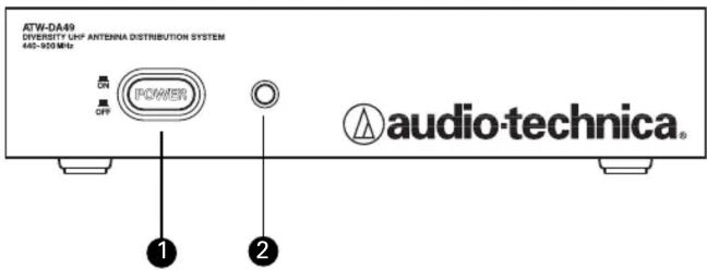
Front Panel Controls and Functions (Fig. A)
- POWER SWITCH: Press switch to apply power to unit. Press again to turn unit off.
- POWER INDICATOR: The indicator will light when power is applied.
Figure A Front Panel
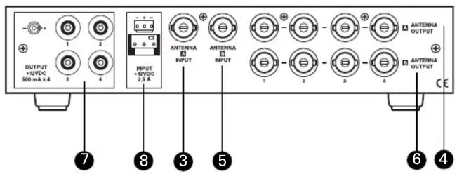
Rear Panel Controls and Functions (Fig. B)
- CHANNEL "A" ANTENNA INPUT: Attach the "A" antenna here, or extend it with a low-loss antenna cable. (Antenna and cable not included.)
- CHANNEL "A" DISTRIBUTION OUTPUTS: Four jacks provide RF distribution to receivers operating within the 440-900 MHz range. Each output should be connected to only one other antenna input. Unused outputs do not require termination.
- CHANNEL "B" ANTENNA INPUT: Attach the "B" antenna here, or extend it with a low-loss antenna cable. (Antenna and cable not included.)
- CHANNEL "B" DISTRIBUTION OUTPUTS: Four jacks provide RF distribution to receivers operating within the 440-900 MHz range. Each output should be connected to only one other antenna input. Unused outputs do not require termination.
- DC OUTPUT JACKS: Provides 12V DC (center positive) at up to 500 mA from each jack to power receivers. Connect the included ATW-RDCN cables here to supply 12V DC to up to four ATW-R2100 or ATW-R3100 (or like-powered) receivers.
- DC POWER INPUT: 3-pin header connector for +12V DC power input.
Figure B Rear Panel
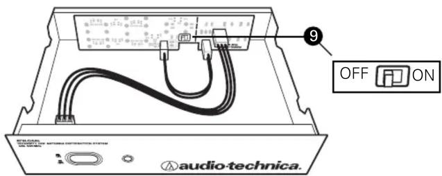
Active Antenna Power Switch (Fig. C)
NOTE: ATW-A49 antennas do not require power. If you are using ATW-A49 antennas, or any passive antennas, leave the switch in the factory-set OFF position. If you have an antenna system that requires power (such as an antenna preamp or booster) you must open the ATW-DA49 assembly and activate a switch on the circuit board. See Fig. C. (This enables the antenna distribution system to pass power through to the antenna.) Current consumption of the preamp or booster should not exceed 100 mA.
9. The unit is shipped with the switch in the "off" position. To change the switch to the "on" position, first be certain the ATW-A49 is not attached to any power source. Next, use a Phillips screwdriver to remove the four cover screws; remove the cover; move the switch into the "on" position. Finally, replace the cover and securely tighten the screws.
Figure C Antenna Power Switch
Front-mount Antennas-ATW-RM1 Rack Mount Hardware Kit (Fig. D)
- The ATW-RM1 rack-mount hardware kit (includes rack ears and hardware) is provided to permit attachment in a standard 19" audio equipment rack.
- Antennas may be mounted on the front of the long rack ear.
The following parts are included in the kit: Long rack ear; short rack ear; two BNC bulkhead connectors with mounting hardware; two 34" BNC-to-BNC cables; six rack-mount screws.
Figure D Front-mount Antennas
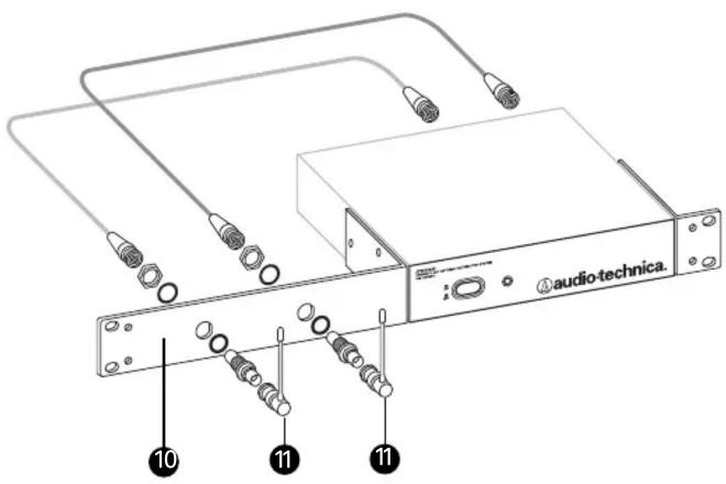
Assembling the ATW-RM1 Rack Mount Hardware Kit (Fig. D)
- Remove the nut and lock-washer from each bulkhead connector. Install the connectors from the front into the two holes in the long rack ear (see Fig. D). Note that the flat on the threaded section must be aligned with the flat in each panel hole.
- Install the lock-washer and nuts (included) over the back of each bulkhead connector. Secure each connector from the back with its lock-washer and nut, tightening the nut firmly.
- Connect one end of each provided BNC-BNC cable to the rear antenna input jacks on the back of the antenna distribution system amplifier. Attach the other end of each cable to the back of the BNC bulkhead connectors. Make certain the bayonet twist-rings are fully latched on the connectors at both ends.
- Finally, mount the receiver's antennas to each of the BNC bulkhead connectors.
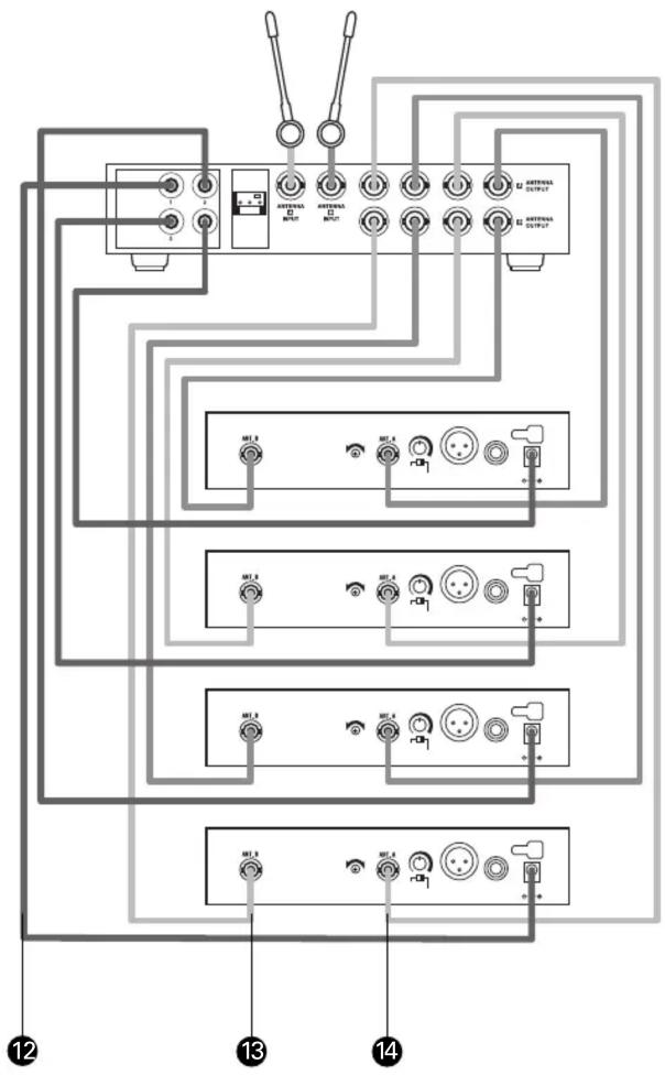
ATW-DA49 Set up (Fig. E)
- +12V DC power is supplied through the ATW-DA49 Antenna Distribution System to each receiver.
- Channel "B" distribution output connects to antenna "B" input jack on receiver.
- Channel "A" distribution output connects to antenna "A" input jack on receiver.
Figure E ATW-DA49 Set Up
flowchart
graph TD
    A["Panel 12"] --> B["Switch 1"]
    A --> C["Switch 2"]
    A --> D["Switch 3"]
    A --> E["Switch 4"]
    A --> F["Switch 5"]
    A --> G["Switch 6"]
    A --> H["Switch 7"]
    A --> I["Switch 8"]
    A --> J["Switch 9"]
    A --> K["Switch 10"]
    A --> L["Switch 11"]
    A --> M["Switch 12"]
    A --> N["Switch 13"]
    A --> O["Switch 14"]
    A --> P["Switch 15"]
    A --> Q["Switch 16"]
    A --> R["Switch 17"]
    A --> S["Switch 18"]
    A --> T["Switch 19"]
    A --> U["Switch 20"]
    A --> V["Switch 21"]
    A --> W["Switch 22"]
    A --> X["Switch 23"]
    A --> Y["Switch 24"]
    A --> Z["Switch 25"]
    A --> AA["Switch 26"]
    A --> AB["Switch 27"]
    A --> AC["Switch 28"]
    A --> AD["Switch 29"]
    A --> AE["Switch 30"]
    A --> AF["Switch 31"]
    A --> AG["Switch 32"]
    A --> AH["Switch 33"]
    A --> AI["Switch 34"]
    A --> AJ["Switch 35"]
    A --> AK["Switch 36"]
    A --> AL["Switch 37"]
    A --> AM["Switch 38"]
    A --> AN["Switch 39"]
    A --> AO["Switch 40"]
    A --> AP["Switch 41"]
    A --> AQ["Switch 42"]
    A --> AR["Switch 43"]
    A --> AS["Switch 44"]
    A --> AT["Switch 45"]
    A --> AU["Switch 46"]
    A --> AV["Switch 47"]
    A --> AW["Switch 48"]
    A --> AX["Switch 49"]
    A --> AY["Switch 50"]
    A --> AZ["Switch 51"]
    A --> BA["Switch 52"]
    A --> BB["Switch 53"]
    A --> BC["Switch 54"]
    A --> BD["Switch 55"]
    A --> BE["Switch 56"]
    A --> BF["Switch 57"]
    A --> BG["Switch 58"]
    A --> BH["Switch 59"]
    A --> BI["Switch 60"]
    A --> BJ["Switch 61"]
    A --> BK["Switch 62"]
    A --> BL["Switch 63"]
    A --> BM["Switch 64"]
    A --> BN["Switch 65"]
    A --> BO["Switch 66"]
    A --> BP["Switch 67"]
    A --> BQ["Switch 68"]
    A --> BR["Switch 69"]
    A --> BS["Switch 70"]
    A --> BT["Switch 71"]
    A --> BU["Switch 72"]
    A --> BV["Switch 73"]
    A --> BW["Switch 74"]
    A --> BX["Switch 75"]
    A --> BY["Switch 76"]
    A --> BZ["Switch 77"]
    A --> CA["Switch 78"]
    A --> CB["Switch 79"]
    A --> CC["Switch 80"]
Specifications
Bandwidth 440-900 MHz
Gain 0 dB typical (within specified bandwidth)
Impedance 50 ohms typical (within specified bandwidth)
Antenna Power (optional) +12V DC, center positive,
100 mA maximum per antenna input (2 total)
Termination Type BNC Female (10 total)
Power Supply Desktop Switching Power Supply
Rated at 3A @ 12V DC or 36 Watts.
Input Voltage 100-240V AC via
detachable IEC 320/C14 cable
Output is provided on an overmolded
3-pin Molex-style termination.
Dimensions (Base unit only) 8.27" (210.0 mm) W x
1.79" (45.5 mm) H x
6.93" (176.0 mm) D
Weight 2.0 lbs. (0.9 kg)
Accessories Included
IEC 320/C14 power cable;10 BNC-to-BNC 34" RF cables; 4 DC power
interconnect cables; ATW-RM1 rack kit for front mounting antennas and adaptation to a 19" rack.
To reduce the environmental impact of a multi-language printed document, product information is available online at www.audio-technica.com in a selection of languages.
Extensive information about using wireless systems and accessories is available on the Audio-Technica Web site at www.audio-technica.com
audio-technica
Audio-Technica U.S., Inc., 1221 Commerce Drive, Stow, Ohio 44224 330/686-2600
Audio-Technica Limited, Old Lane, Leeds LS11 8AG England (0)113 277 1441
- WARNING: This apparatus must be grounded.
- ATW-DA49InstallationandOperation
- Power Connections
- Front Panel Controls and Functions (Fig. A)
- Rear Panel Controls and Functions (Fig. B)
- Active Antenna Power Switch (Fig. C)
- Front-mount Antennas-ATW-RM1 Rack Mount Hardware Kit (Fig. D)
- Assembling the ATW-RM1 Rack Mount Hardware Kit (Fig. D)
- ATW-DA49 Set up (Fig. E)
- Specifications
Brand : Audio-Technica
Model : ATW-DA49
Category : Separator