
LGS310MPC - Switch LINKSYS - Free user manual and instructions
Find the device manual for free LGS310MPC LINKSYS in PDF.

| Product Type | Managed Gigabit PoE+ Switch |
| Ports | 8 Gigabit PoE+ ports + 2 Gigabit SFP/RJ45 combo ports |
| PoE Budget | 410 Watts total |
| Switching Capacity | 20 Gbps |
| Forwarding Rate | 14.88 Mpps |
| Management | Web GUI, CLI, SNMP v1/v2c/v3, RMON |
| VLAN Support | 802.1Q VLAN, up to 4094 VLANs, Voice VLAN |
| Spanning Tree | STP, RSTP, MSTP |
| Link Aggregation | Up to 8 groups, 8 ports per group, LACP |
| IGMP/MLD Snooping | IGMPv1/v2/v3, MLDv1/v2 snooping |
| Security | 802.1X, ACL (MAC, IPv4, IPv6), Port Security, DHCP Snooping, DoS Prevention |
| QoS | 8 priority queues, CoS, DSCP, bandwidth control, storm control |
| Port Mirroring | Up to 4 sessions, one-to-one or many-to-one |
| LLDP | IEEE 802.1AB LLDP |
| Loopback Detection | LBD to prevent loops |
| Energy Efficient Ethernet | EEE (802.3az) per port |
| Jumbo Frame | Up to 9K bytes |
| Power Supply | Internal, 100-240V AC, 50/60Hz |
| Dimensions (W x D x H) | 330 x 230 x 44 mm (19-inch rackmount) |
| Weight | 3.0 kg |
| Cooling | Fan(s) with status monitoring |
| Operating Temperature | 0°C to 50°C |
| Storage Temperature | -40°C to 70°C |
| Operating Humidity | 10% to 90% non-condensing |
| Maintenance & Safety | Use dry cloth for cleaning; do not expose to liquids; keep ventilation clear |
Frequently Asked Questions - LGS310MPC LINKSYS
User questions about LGS310MPC LINKSYS
0 question about this device. Answer the ones you know or ask your own.
Ask a new question about this device
Download the instructions for your Switch in PDF format for free! Find your manual LGS310MPC - LINKSYS and take your electronic device back in hand. On this page are published all the documents necessary for the use of your device. LGS310MPC by LINKSYS.
USER MANUAL LGS310MPC LINKSYS
Ethernet Switch Features 4
System....4
Summary 4
IP Settings 5
ARP Settings 10
Neighbor Discovery (ND) table 13
System Time 14
Port Settings....16
SFP Information....17
DHCP Snooping 18
PoE 21
EEE....24
L2 Feature.... 25
Link Aggregation 25
Mirror Settings....29
STP 31
LBD 44
MAC Address Table.... 45
LLDP 47
IGMP Snooping 50
MLD Snooping 55
Status....56
Mode 56
Report......56
Suppression 56
Multicast Filtering....59
Jumbo Frame 59
VLAN 60
802.1Q 61
PVID 61
Voice VLAN 63
Management....67
System Information....67
User Management 67
Dual Image 68
ACL 69
MAC ACL....70
MAC ACE 70
IPv4 ACL....72
IPv4 ACE 72
IPv6 ACL....75
IPv6 ACE 75
ACL Binding....77
QoS....77
Global Settings 78
CoS Mapping 79
DSCP Mapping....80
Port Settings....81
Advanced Settings 82
Bandwidth Control 84
Storm Control 85
Security 86
802.1x 86
RADIUS Server 91
Access....92
Port Security....93
Port Isolation....94
DoS....95
Monitoring 95
Port Statistics....95
RMON 96
Log....100
Diagnostics....103
Cable Diagnostics....103
Ping Test....104
IPv6 Ping Test ....105
Trace Route....106
Maintenance....107
Configuration Manager....107
Firmware Upgrade....108
Reset....108
Ethernet Switch Features
System
Summary
The Summary page shows general system information for the Switch including the device name, firmware version, serial number, base MAC address, system uptime and fan status.
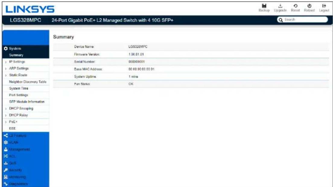
| Device Name | Displays the model name of the device. |
| FW Version | Displays the installed firmware version of the device. |
| Serial Number | Displays the serial number of the device. |
| Base MAC Address | Displays the MAC base address of the device. |
| System Uptime | Displays the number of days, hours, and minutes since the last system restart. The System Uptime is displayed in the following format: days, hours, and minutes. |
| Fan Status | Displays the fan status |
IP Settings
This switch supports multiple IP interfaces can be configurable. There are 4 IPv4 address and 4 IPv6 link local address, and 16 global IPv6 address share with 4 IP interfaces.
The IP Setting page contains fields for assigning IP addresses. IP addresses are either defined as static or are retrieved using the Dynamic Host Configuration Protocol (DHCP). DHCP assigns dynamic IP addresses to devices on a network. DHCP ensures that network devices can have a different IP address every time the device connects to the network.
To access the page, click IP Settings under the System menu.
IPv4 Management
This page provides you to modify the management VLAN interface either set to static IP or DHCP/BOOTP for auto-configuration.
IPv4 Management
| VlanID | Address | Subnet Mask | Configuration |
| 1 | 192.168.30.107 | 255.255.255.0 | DHCP |
IPv4 Management
| VlanID | Address | Subnet Mask | Configuration |
| 1 | 192.168.30.107 | 255.255.255.0 | Static |
Important--If the device fails to retrieve on IP address through DHCP, the default IP address is 192.168.1.251 and the factory default subnet mask is 255.255.255.0.
| Dynamic IP Address (DHCP/BOOTP) | Enables the IP address to be configured automatically by the DHCP server. Select this option if you have a DHCP server that can assign the Switch an IP address, subnet mask, default gateway IP address, and a domain name server IP address automatically. Selecting this field disables the IP Address, Subnet Mask fields. |
| Static IP Address | Allows the entry of an IP address, subnet mask for the Switch. Select this option if you don't have a DHCP server or if you wish to assign a static IP address to the Switch. |
| IP Address | This field allows the entry of an IPv4 address to be assigned to this IP interface. Enter the IP address of your Switch in dotted decimal notation. The factory default value is: 192.168.1.251 |
| Subnet Mask | A subnet mask separates the IP address into the network and host addresses. A bitmask that determines the extent of the subnet that the Switch is on. This should be labeled in the form: xxx.xxx.xxx.xxx, where each xxx is a number (represented in decimals) between 0 and 255. The value should be 255.0.0.0 for a Class A network, 255.255.0.0 for a Class B network, and 255.255.255.0 for a Class C network, but custom subnet masks are allowed. Enter the IP subnet mask of your Switch in dotted decimal notation. The factory default value is: 255.255.255.0 |
Click the button 📋 to modify specific IPv4 interface.
Click the Apply button √ to accept the changes or the Cancel button ✗ to discard them.
IPv6 Management
IPv6 is an upgraded version to IPv4, providing more available IP addresses as well as other benefits. To access the switch over an IPv6 network you must first configure it with IPv6 information (IPv6 address, prefix length, and LinkLocal or Global address type). To configure IPv6 for the Switch, select VLAN interface to modify or press add button to add a new IPv6 address.
IPv6 Management
| Interface | VLAN interface need to add / modify. |
| Address / Prefix Length | This field allows the entry of an IPv6 address/prefix to be assigned to this IP interface. |
| Address Type | Unicast for IPv6 Global address type and LinkLocal for IPv6 link local address type. |
Click the button 📋 to modify specific IPv6 interface and button 🔒 to delete an IPv6 interface entry manually.
Click the Apply button to accept the changes or the Cancel button to discard them.
IPv4 Network
In this page, you can add IPv4 address on un-management VLAN.
IPv4 Network
| VlanID | Address | Subnet Mask |  |
| 10 | 192.168.10.101 | 255.255.255.0 |  |
| 20 | 20.20.20.100 | 255.255.255.0 |  |
| 30 | 30.30.30.100 | 255.255.255.0 |  |
IPv4 Network
| VlanID | Address | Subnet Mask |
| 10 | 192.168.10.101 | 255.255.255.0 |
| 20 | 20.20.20.100 | 255.255.255.0 |
| 30 | 30.30.30.100 | 255.255.255.0 |
| VLAN | Specify the VLAN ID. |
| IP Address | This field allows the entry of an IPv4 address to be assigned to this IP interface. Enter the IP address of your Switch in dotted decimal notation. |
| Subnet Mask | A subnet mask separates the IP address into the network and host addresses. A bitmask that determines the extent of the subnet that the Switch is on. This should be labeled in the form: xxx.xxx.xxx.xxx, where each xxx is a number (represented in decimals) between 0 and 255. The value should be 255.0.0.0 for a Class A network, 255.255.0.0 for a Class B network, and 255.255.255.0 for a Class C network, but custom subnet masks are allowed. Enter the IP subnet mask of your Switch in dotted decimal notation. The factory default value is: 255.255.255.0. |
Click the button 📋 to modify specific IPv4 interface.
Click the Apply button √ to accept the changes or the Cancel button ✗ to discard them.
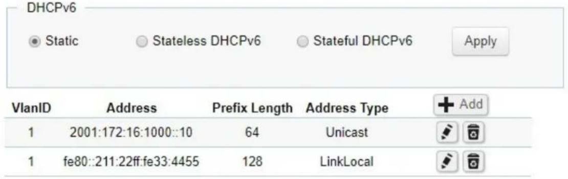
IPv6 Network
In this page, you can add IPv6 address on un-management VLAN.
IPv6
| VlanID | Address | Prefix Length | Address Type |
| 10 | 2001:172:16:1000::10 | 64 | Unicast |
| 10 | fe80::211:22ff:fe33:4455 | 128 | LinkLocal |
IPv6
| VlanID | Address | Prefix Length | Address Type |  |
| 10 | 2001:172:16:1000::10 | 64 | Unicast |  |
| 10 | fe80::211:22ff:fe33:4455 | 128 | LinkLocal |  |
| VLAN | Specify the VLAN ID. |
| IP Address | This field allows the entry of an IPv6 address/prefix to be assigned to this IP interface. |
| Subnet Mask | Unicast for IPv6 Global address type and LinkLocal for IPv6 link local address type |
Click the button 📋 to modify specific IPv6 interface and button 🔒 to delete an IPv6 interface entry.
Click the Apply button √ to accept the changes or the Cancel button ✗ to discard them.
DNS Servers
DNS (Domain Name System) can transfer host name to IP address. This switch supports 4 IP address list of DNS servers. If DHCP is selected in IPv4 interface and DNS info in DHCP option will auto add in DNS IP address list.
DNS Servers
| Name | Address | |
| DNS 1 | 10.0.91.241 | |
| DNS 2 | 10.0.91.240 | |
| DNS 3 | 2001:172:16:1000::100 | |
| DNS 4 | n/a |
| Address | This field allows the entry of an IPv4/IPv6 address to be DNS server IP address. |
Click the button 📋 to modify specific IPv4 interface
Click the Apply button √ to accept the changes or the Cancel button ✗ to discard them.
ARP Settings
To access the page, click ARP Settings under the System menu.
Address Resolution Protocol (ARP) Global

Apply
ARP Global
Set retry times and age out timer for ARP table.
| Max retries | Max ARP request retries times if switch can't get ARP reply. |
| Timeout | Aging time for Dynamic ARP entries. |
Click Apply to save settings.
Address Resolution Protocol (ARP) table
Display ARP table and ARP entries in switch. Administrator can move Dynamic ARP entry as Static ARP entry, create a Static ARP entry, and delete an ARP entry.
Address Resolution Protocol (ARP) table
| Address | MAC Address | Interface | Mapping |
| 192.168.0.212 | 84:16:f9:00:46:30 | vlan1 | Dynamic |
Address Resolution Protocol (ARP) table
| Address | MAC Address | Interface | Mapping |
| 192.168.0.212 | 84:16:f9:00:46:30 | vlan1 | Dynamic |
| xxx.xxx.xxx.xxx | xx:xx:xx:xx:xx:xx | vlan 1 |
| Move to Static | Administrator can move Dynamic ARP entry as Static ARP entry. Static ARP will not take effect by timeout timer in global settings. |
| Address | This field allows the entry of an IPv4 address to be IP address in ARP entry. |
| MAC Address | This field allows the entry of a MAC address format to be MAC address in ARP entry. |
| Interface | Select or display ARP entry belongs which IP interface. |
| Mapping | To display status of ARP entry. |
Click the button 📋 to move dynamic ARP to static ARP and button 🔒 to delete an ARP entry manually.
Click the Apply button √ to accept the changes or the Cancel button ✗ to discard them.
Address Resolution Protocol (ARP) Statistics
To display counters related to ARP.
Address Resolution Protocol (ARP) Statistics
| Total: | 97 |
| Bad type: | 0 |
| Bad length: | 0 |
| Base Address: | 60 |
| Request Discards: | 12 |
| In Requests: | 5 |
| Received: | 20 |
| Request Sent: | 0 |
| Drop: | 0 |
| Rreplied: | 5 |
Static Route
Switch will forward IP packets follow ARP/ND table and Static route configuration.
Static route can be configurable by administrator manually. Static route can also assign a next hop for stub network, or a default gateway for whole switch.
The DIP filed in packets were not in IP subnet range of switch and also not hit by any route configuration, will forward to default gateway then.
All gateway fields need to be including of subnet range of switch IP interfaces.
To access the page, click Static Route under the System menu.
IPv4
IPv4 Route
| Destination IP | Subnet Mask | Gateway | Interface | Distance (Metric) | Routing Protocol | + Add |
| 0.0.0.0 | 0.0.0.0 | 192.168.0.212 | 1 | Static | ||
| 192.168.0.0 | 255.255.240.0 | 0.0.0.0 | vlan1 | 0 | Connected |
IPv4 Route
| Destination IP | Subnet Mask | Gateway | Interface | Distance (Metric) | Routing Protocol | |
| 0.0.0.0 | 0.0.0.0 | 192.168.0.212 | 1 | Static | ||
| 192.168.0.0 | 255.255.240.0 | 0.0.0.0 | vlan1 | 0 | Connected | |
| 1~254 | √ ✗ |
Important—Destination IP and Subnet Mask are set to 0.0.0.0, then this entry will be default
| Destination IP | The DIP field in packets need to route. |
| Subnet Mask | The field decides the range that packets hit this route entry. |
| Gateway | The next hop IPv4 address if packets hit route entry. |
Click the Apply button √ to accept the changes or the Cancel button ✗ to discard them.
IPv6
IPv6 global address in IP interface is needed before creating IPv6 static route.
IPv6 Route
| Destination IP | Prefix Length | Gateway | Interface | Distance (Metric) | Routing Protocol | + Add |
| :: | 0 | 1234::1234 | vlan1 | 2 | Static | |
| 1234:: | 64 | :: | vlan1 | 1 | Connected |
IPv6 Route
| Destination IP | Prefix Length | Gateway | Interface | Distance (Metric) | Routing Protocol |
| : | 0 | 1234:1234 | vlan1 | 2 | Static |
| 1234: | 64 | : | vlan1 | 1 | Connected |
| 0 ~ 128 | 1 ~ 254 |
Important—If the Destination IP is set to: and the Prefix Length is set to 0, then this entry will be default gateway entry in route table.
| Destination IP | The DIP field in packets need to route. |
| Prefix Length | The field decides the range that packets hit this route entry. |
| Gateway | The next hop IPv6 address with global format if packets hit route entry. |
Click Apply to save settings.
Neighbor Discovery (ND) table
ND is responsible for gathering information from nearby nodes in IPv6 format.
Neighbor Discovery (ND) Table
| IPv6 Address | Link-layer Addr | State | Interface |
| fe80::29:6a07:8b56:2cc4 | 34:a3:95:df:15:59 | Stale | vlan1 |
| IPv6 Address | This field allows the entry of an IPv6 address to be IP address in ND entry. |
| Link-layer Addr | This field allows the entry of a MAC address format to be MAC address in ND entry. |
| Interface | Select or display ND entry belongs which IP interface. |
| State | Displays the status of ARP entry. |
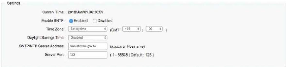
System Time
Use the System Time screen to view and adjust date and time settings.
The Switch supports Simple Network Time Protocol (SNTP). SNTP assures accurate network device clock time synchronization up to the millisecond. Time synchronization is performed by a network SNTP server. This switch operates only as an SNTP client and cannot provide time services to other systems.
System Time
Apply
System Time
Apply
| Current time | Displays the current system time. |
| Enable SNTP | Select whether to enable or disable system time synchronization with an SNTP server. |
| Time Zone | Configure the time zone setting either by setting GMT difference or by country. |
| Daylight Savings Time | Select from Disabled, Recurring or Non-recurring. |
| Daylight Savings Time Offset | Enter the time of Daylight Savings Time Offset. |
| Recurring From | Select the Day, Week, Month, and Hour from the list. |
| Recurring To | Select the Day, Week, Month, and Hour from the list. |
| SNTP/NTP Server Address | Enter the IP address or hostname of the SNTP/NTP server. |
| Server Port | Enter the server port of the SNTP/NTP server. |
To configure date/time through SNTP:
- Next to the Enable SNTP, select Enable.
- In the Time Zone Offset list, select by country or by the GMT time zone in which the Switch is located.
- Next select Disabled or Recurring for Daylight Savings Time. Daylight saving is a period from late spring to early fall when many countries set their clocks ahead of normal local time by one hour to give more daytime light in the evening.
- In the SNTP/NTP Server Address field, enter the IP address or the host name of the SNTP/NTP server.
- Finally, enter the port number on the SNTP server to which SNTP requests are sent. The valid range is from 1-65535. The default is: 123.
- Click Apply to update the system settings.
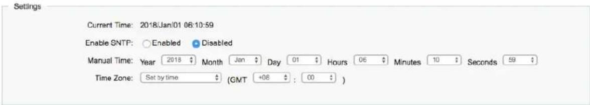
To configure date/time manually:
- Next to the Enable SNTP, select Disable.
-
In the Manual Time field, use the drop-down boxes to manually select the date and time you wish to set.
-
In the Time Zone Offset list, select by country or by the Coordinated Universal Time (UTC/GMT) time zone in which the Switch is located.
-
Next select Disabled, Recurring or Non-recurring for Daylight Savings Time. Daylight saving is a period from late spring to early fall when many countries set their clocks ahead of normal local time by one hour to give more daytime light in the evening.
-
Click Apply to update the system settings.
Port Settings
Use this screen to view and configure Switch port settings. The Port Settings page allows you change the configuration of the ports on the Switch in order to find the best balance of speed and flow control according to your preferences. Configuring Gigabit ports require additional factors to be considered when arranging your preferences for the Switch compared to 10/100Mb ports.
To access the page, click Port Settings under the System menu.
Port Settings
| Port | Link Status | Mode | Flow Control | Port Description | |
| Auto | Disabled | ||||
| 1 | Link Up | Auto-1G/Full | Enabled | ||
| 2 | Link Up | Auto-1G/Full | Enabled | ||
| 3 | Link Down | Auto | Enabled | ||
| 4 | Link Down | Auto | Enabled | ||
| 5 | Link Down | Auto | Enabled | ||
| 6 | Link Down | Auto | Enabled | ||
| 7 | Link Down | Auto | Enabled | ||
| 8 | Link Down | Auto | Enabled | ||
| trunk1 | Link Down | Auto | Enabled | ||
| trunk2 | Link Down | Auto | Enabled | ||
| trunk3 | Link Down | Auto | Enabled | ||
| trunk4 | Link Down | Auto | Enabled | ||
| trunk5 | Link Down | Auto | Enabled | ||
| trunk6 | Link Down | Auto | Enabled | ||
| trunk7 | Link Down | Auto | Enabled | ||
| trunk8 | Link Down | Auto | Enabled |
Apply
| Port | Displays the port number. |
| Link Status | Indicates whether the link is up or down. |
| Mode | Select the speed and the duplex mode of the Ethernet connection on this port. Selecting Auto (auto-negotiation) allows one port to negotiate with a peer port automatically to obtain the connection speed and duplex mode that both ends support. When auto-negotiation is turned on, a port on the Switch negotiates with the peer automatically to determine the connection speed and duplex mode. If the peer port does not support auto-negotiation or turns off this feature, the Switch determines the connection speed by detecting the signal on the cable and using half duplex mode. When the Switch's auto-negotiation is turned off, a port uses the pre-configured speed and duplex mode when making a connection, thus requiring you to make sure that the settings of the peer port are the same in order to connect. |
| Flow Control | A concentration of traffic on a port decreases port bandwidth and overflows buffer memory causing packet discards and frame losses. Flow Control is used to regulate transmission of signals to match the bandwidth of the receiving port. The Switch uses IEEE 802.3x flow control in full duplex mode and backpressure flow control in half duplex mode.IEEE 802.3x flow control is used in full duplex mode to send a pause signal to the sending port, causing it to temporarily stop sending signals when the receiving port memory buffers fill.Back Pressure flow control is typically used in half duplex mode to send a "collision" signal to the sending port (mimicking a state of packet collision) causing the sending port to temporarily stop sending signals and resend later. |
| Port Description | For user's convenience, user can have a description of this port by input text into this field. |
Click Apply to save settings.
SFP Information
The SFP Information screen contains SFP Module status and basic information. To access the page, click SFP Information under the System menu.
SFP Module Information
Display Module Information in: Port 25
| Connector Type: | LC [ 0x07 ] |
| 10G Ethernet Compliance Codes: | 10G-SR [ 0x10 ] |
| Ethernet Compliance Codes: | Not compliant [ 0x00 ] |
| Nominal Bit Rate: | 10.3 Gbps |
| Laser Wavelength: | 850 nm |
| Vendor OUI: | 0x00 0x0f 0x99 |
| Vendor Name: | APAC Opto |
| Part Number: | LM28-H3S-TC-N |
| Revision Number: | 0000 |
| Serial Number: | DA02150041 |
| Date Code: | 01/17/2014 |
| DDM Type: | 0x68 |
DDM Information :
| Temperature: | 24.80 °C |
| Voltage: | 3.28 V |
| Tx Laser Bias: | 5.46 mA |
| Tx Power: | -5.30 dBm |
| Rx Power: | -7.97 dBm |
| TX Fault State: | False |
| RX LOS State: | False |
| Alarm Flag: | No Alarm. |
| Warn Flag: | No Warn. |
| Port | The port number of SFP port to be displayed. |
DHCP Snooping
DHCP snooping is a DHCP security feature that provides security by filtering untrusted DHCP messages and by building and maintaining a DHCP snooping binding table. An untrusted message is a message that is received from outside the network or firewall and that can cause traffic attacks within your network.
The DHCP snooping binding table contains the MAC address, IP address, lease time, binding type, VLAN number, and interface information that corresponds to the local untrusted interfaces of a switch; it does not contain information regarding hosts interconnected with a trusted interface. An untrusted interface is an interface that is configured to receive messages from outside the network or firewall. A trusted interface is an interface that is configured to receive only messages from within the network.
DHCP snooping acts like a firewall between untrusted hosts and DHCP servers. It also gives you a way to differentiate between untrusted interfaces connected to the end-user and trusted interfaces connected to the DHCP server or another switch.
Global Settings
The global settings allow you to enable or disable DHCP snooping feature. You can also enable the MAC Verify at this page.
Settings

To access this page, click DHCP snooping under the System menu.
| DHCP Snooping Status | Enable or Disable the DHCP snooping feature. |
| Mac Verify | Enable the MAC address verify or not. |
VLAN Settings
| VLAN ID | DHCP Snooping Status | |
| 1 | Disabled | |
| 10 | Disabled | |
| 20 | Disabled | |
| 30 | Disabled | |
| 40 | Disabled | |
| 50 | Disabled |
| VLAN ID | Specify the VLAN to have the DHCP Snooping function. |
| DHCP Snooping Status | Enable or Disable the DHCP snooping on the VLAN. |
Trust Port Settings
Set the DCHP Server at trusted ports.
| Port | State | |
| Untrusted ▼ | ||
| 1 | Trusted | |
| 2 | Trusted | |
| 3 | Trusted | |
| 4 | Trusted | |
| 5 | Trusted | |
| 6 | Trusted | |
| 7 | Trusted | |
| 8 | Trusted | |
| 9 | Trusted | |
| 10 | Trusted | |
| 11 | Trusted | |
| 12 | Trusted | |
| 13 | Trusted |
| Port | Select the port as the DHCP server trusted port. |
| State | Set the port to be trust or un-trust port. |
Binding list
Display the DHCP client information.
| VID | Display the VLAN id of client information. |
| Port | Display the port number of client information. |
| MAC address | Display the MAC address of client information. |
| IP address | Display the IP address of client information. |
VLAN Statistics
Display the DHCP snooping packet information on each VLAN
Vlan Statistics
| Vian | RXDiscovers | RXRequests | RXReleases | RXDeclines | RXInforms | TXOffers | TXAcks | TXNaks | MACDiscard | ServerDiscard | OptionDiscard | TotalDiscard |
| 1 | 1 | 1 | 1 | 0 | 0 | 0 | 0 | 0 | 0 | 0 | 0 | 0 |
| 10 | 0 | 0 | 0 | 0 | 0 | 0 | 0 | 0 | 0 | 0 | 0 | 0 |
| 20 | 0 | 0 | 0 | 0 | 0 | 0 | 0 | 0 | 0 | 0 | 0 | 0 |
| 30 | 0 | 0 | 0 | 0 | 0 | 0 | 0 | 0 | 0 | 0 | 0 | 0 |
| 40 | 0 | 0 | 0 | 0 | 0 | 0 | 0 | 0 | 0 | 0 | 0 | 0 |
| 50 | 0 | 0 | 0 | 0 | 0 | 0 | 0 | 0 | 0 | 0 | 0 | 0 |
PoE
The PoE management page contains PoE subsystem information for monitoring the current power usage and assigns the total amount of power the Switch can provide to all of its PoE ports. To access the page, click PoE under the System menu.
Power Budget
Power Budget
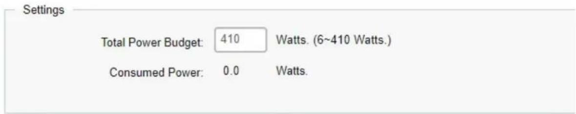
Total Power Budget: Enter the amount of power the Switch can provide to all ports.
Consumed Power: Displays the total amount of power (in watts) currently being delivered to all PoE ports.
NOTE: With different platform, the total power budget could be different.
PoE Port Settings
| PoE Port Settings | |||||||||
| Port | State | Priority | Power Limit Type | User Power Limit(W) | Status | Class | Output Voltage (V) | Output Current (mA) | |
| ☐ | Enabled | Low | Auto Class | 31 | |||||
| ☐ | 1 | Enabled | Low | Auto Class | Searching | ||||
| ☐ | 2 | Enabled | Low | Auto Class | Searching | ||||
| ☐ | 3 | Enabled | Low | Auto Class | Searching | ||||
| ☐ | 4 | Enabled | Low | Auto Class | Searching | ||||
| ☐ | 5 | Enabled | Low | Auto Class | Searching | ||||
| ☐ | 6 | Enabled | Low | Auto Class | Searching | ||||
| ☐ | 7 | Enabled | Low | Auto Class | Searching | ||||
| ☐ | 8 | Enabled | Low | Auto Class | Searching | ||||
| Port | Displays the specific port for which PoE parameters are defined. PoE parameters are assigned to the powered device that is connected to the selected port. |
| State | Displays the active participating members of the trunk group. |
| Priority | Select the port priority if the power supply is low. The field default is Low. For example, if the power supply is running at 99% usage, and port 1 is prioritized as high, but port 6 is prioritized as low, port 1 is prioritized to receive power and port 6 may be denied power.Low: Sets the PoE priority level as low.Medium: Sets the PoE priority level as medium.High: Sets the PoE priority level as high.Critical: Sets the PoE priority level as critical. |
| PowerLimit Type | Shows the classification of the powered device. The class defines the maximum power that can be provided to the powered device. The possible field values are:Class 0: The maximum power level at the Power Sourcing Equipment is 15.4 Watts.Class 1: The maximum power level at the Power Sourcing Equipment is 4.0 Watts.Class 2: The maximum power level at the Power Sourcing Equipment is 7.0 Watts.Class 3: The maximum power level at the Power Sourcing Equipment is 15.4 Watts.Class 4: The maximum power level at the Power Sourcing Equipment is 30 Watts. |
| Class (User | Select this option to base the power limit on the value configured in the User |
| Defined) | Power Limit field. |
| User PowerLimit | Set the maximum amount of power that can be delivered by a port.Note: The User Power Limit can only be implemented when the Class value is set to User-Defined. |
| Status | Shows the port's PoE status. The possible field values are:Delivering Power: The device is enabled to deliver power via the port.Disabled: The device is disabled for delivering power via the port.Test Fail: The powered device test has failed. For example, a port could not be enabled and cannot be used to deliver power to the powered device.Testing: The powered device is being tested. For example, a powered device is tested to confirm it is receiving power from the power supply.Searching: The device is currently searching for a powered device. Searching is the default PoE operational status.Fault: The device has detected a fault on the powered device when the port is forced on. For example, the power supply voltage is out of range, a short occurs, a communication or there is a communication error with PoE devices, or an unknown error occurs. |
Click Apply to save settings.
EEE
Energy Efficient Ethernet (EEE), an Institute of Electrical and Electronics Engineers (IEEE) 802.3az standard, reduces the power consumption of physical layer devices during periods of low link utilization. EEE saves energy by allowing PHY non-essential circuits shut down when there is no traffic.
Network administrators have long focused on the energy efficiency of their infrastructure, and the Linksys Layer 2 Switch complies with the IEEE's Energy-Efficient Ethernet (EEE) standard. The EEE compliant Switch offers users the ability to utilize power that Ethernet links use only during data transmission. Lower Power Idle (LPI) is the method for achieving the power saving during Ethernet ideal time.
Use the EEE configuration page to configure Energy Efficient Ethernet.
| Energy-Efficient Ethernet | ||
| Port | EEE Status | |
| □ | Disabled | |
| □ | 1 | Disabled |
| □ | 2 | Disabled |
| □ | 3 | Disabled |
| □ | 4 | Disabled |
| □ | 5 | Disabled |
| □ | 6 | Disabled |
| □ | 7 | Disabled |
| □ | 8 | Disabled |
| □ | 9 | Disabled |
| □ | 10 | Disabled |
| Port | Display the port for which the EEE setting is displayed. |
| EEE Status | Enable or disable EEE for the specified port. |
Click Apply to save settings.
L2 Feature
The L2 Feature tab exhibits complete standard-based Layer 2 switching capabilities, including: Link Aggregation, 802.1D Spanning Tree Protocol, 802.1w Rapid Spanning Tree Protocol, 802.1s Multiple Spanning Tree Protocol, MAC Address Table, Internet Group Management Protocol (IGMP) Snooping, Port Mirroring, 802.1ab Link Layer Discovery Protocol (LLDP), and Multicast Listener Discovery (MLD) snooping. Utilize these features to configure the Switch to your preferences.
Link Aggregation
A Link Aggregation Group (LAG) optimizes port usage by linking a group of ports together to form a single, logical, higher-bandwidth link. Aggregating ports multiplies the bandwidth and increases port flexibility for the Switch. Link Aggregation is most commonly used to link a bandwidth intensive network device (or devices), such as a server, to the backbone of a network.
The participating ports are called Members of a port trunk group. Since all ports of the trunk group must be configured to operate in the same manner, the configuration of the one port of the trunk group is applied to all ports of the trunk group. Thus, you will only need to configure one of any of the ports in a trunk group. A specific data communication packet will always be transmitted over the same port in a trunk group. This ensures the delivery of individual frames of a data communication packet will be received in the correct order. The traffic load of the LAG will be balanced among the ports according to Aggregate Arithmetic. If the connections of one or several ports are broken, the traffic of these ports will be transmitted on the normal ports, so as to guarantee the connection reliability.
When you aggregate ports, the ports and LAG must fulfill the following conditions:
• All ports within a LAG must be the same media/format type.
• A VLAN is not configured on the port.
• The port is not assigned to another LAG.
• The Auto-negotiation mode is not configured on the port.
• The port is in full-duplex mode.
- All ports in the LAG have the same ingress filtering and tagged modes.
- All ports in the LAG have the same back pressure and flow control modes.
• All ports in the LAG have the same priority.
• All ports in the LAG have the same transceiver type.
- Ports can be configured as LACP ports only if the ports are not part of a previously configured LAG.
LACP is a dynamic protocol which helps to automate the configuration and maintenance of LAG's.
The main purpose of LACP is to automatically configure individual links to an aggregate bundle, while adding new links and helping to recover from link failures if the need arises. LACP can monitor to verify if all the links are connected to the authorized group. LACP is a standard in
computer networking; hence LACP should be enabled on the Switch's trunk ports initially in order for both the participating Switches/devices that support the standard to use it.
Port Trunking
Port Trunking allows you to assign physical links to one logical link that functions as a single, higher-speed link, providing dramatically increased bandwidth. Use Port Trunking to bundle multiple connections and use the combined bandwidth as if it were a single larger pipe.
Important: You must enable Trunk Mode before you can add a port to a trunk group.
| Port Trunking | ||||
| Group | Active Ports | Member Ports | Mode | |
| 1 | Disabled | |||
| 2 | Disabled | |||
| 3 | Disabled | |||
| 4 | Disabled | |||
| 5 | Disabled | |||
| 6 | Disabled | |||
| 7 | Disabled | |||
| 8 | Disabled | |||
| Group | Displays the number of the given trunk group. You can utilize up to 8 link aggregation groups and each group consisting up to 8 ports on the Switch. |
| Active Ports | Displays the active participating members of the trunk group. |
| Member Port | Select the ports you wish to add into the trunk group. Up to eight ports per group can be assigned.Static: The Link Aggregation is configured manually for specified trunk group.LACP: The Link Aggregation is configured dynamically for specified trunk group. |
| Mode | LACP allows for the automatic detection of links in a port trunking group when connected to a LACP-compliant Switch. You will need to ensure that both the Switch and device connected to are in the same mode in order for them to function, otherwise they will not work. Static configuration is used when connecting to a Switch that does not support LACP. |
Click the Apply button √ to accept the changes or the Cancel button ✗ to discard them.
LACP Settings
Assign a system priority to run with Link Aggregation Control Protocol (LACP) and is become for a backup link if a link goes down. The lowest system priority is allowed to make decisions about which ports it is actively participating in in case a link goes down. If two or more ports have the same LACP port priority, the port with the lowest physical port number will be selected as the backup port. If a LAG already exists with the maximum number of allowed port members, and LACP is subsequently enabled on another port using a higher priority than an existing member, the newly configured port will replace the existing port member that has a lower priority. A smaller number indicates a higher priority level. The range is from 0-65535 and default is: 32768.
LACP Settings
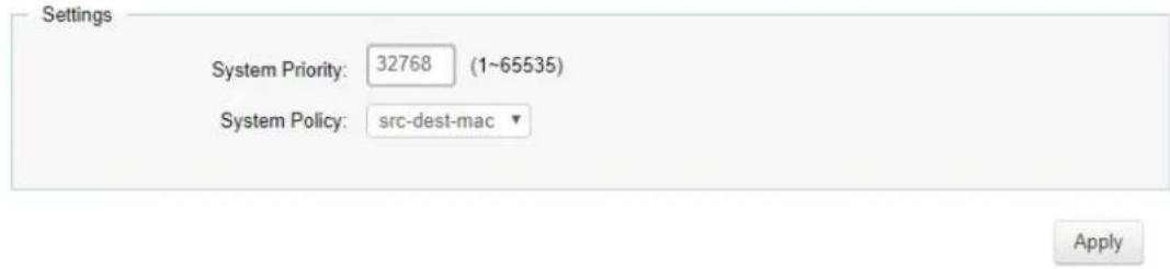
| System Priority | Enter the LACP priority value to the system. The default is 32768 and the range is from 1 to 65535. |
| System Policy | Select trunk load balance policy to the system. The default is src-dest-mac. |
Click Apply to save settings.
LACP Timeout
Link Aggregation Control Protocol (LACP) allows the exchange of information with regard to the link aggregation between two members of aggregation. The LACP Time Out value is measured in a periodic interval. Check first whether the port in the trunk group is up. When the interval expires, it will be removed from the trunk. Set a Short Timeout (one second) for busy trunked links to ensure that disabled ports are removed from the trunk group as soon as possible. The default value for LACP time out is: Long Timeout.
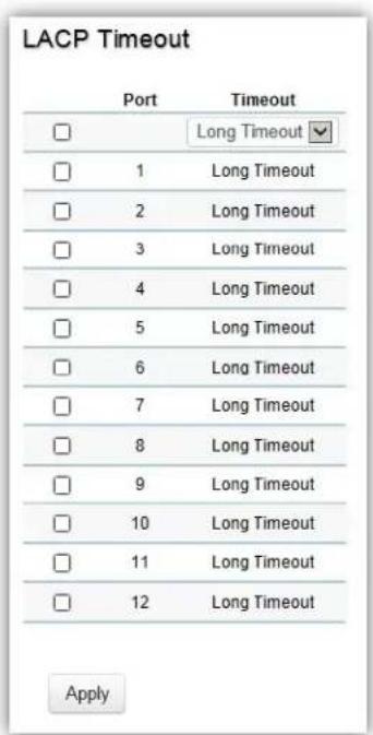
| Timeout | Select the administrative LACP timeout.Long Timeout: The LACP PDU will be sent for every 30 seconds, and the LACP timeout value is 90 seconds. |
| Short Timeout: The LACP PDU will be sent every second. The timeout value is 3 seconds. |
Click Apply to save settings.
Mirror Settings
Mirrors network traffic by forwarding copies of incoming and outgoing packets from specific ports to a monitoring port. The packet that is copied to the monitoring port will be the same format as the original packet.
Port mirroring is useful for network monitoring and can be used as a diagnostic tool. Use port mirroring to send traffic to applications that analyze traffic for purposes such as monitoring compliance, detecting intrusions, monitoring and predicting traffic patterns, and other correlating events. Port Mirroring is needed for traffic analysis on a Switch because a Switch normally sends packets only to the port to which the destination device is connected. The analyzer captures and evaluates the data without affecting the client on the original port. Port mirroring can consume significant CPU resources while active, so be cautious of such usage when configuring the Switch.
Mirror Settings
| Session ID | Destination Port | Source TX Port | Source RX Port | Ingress State | Session State | |
| 1 | N/A | Disabled | Disabled | |||
| 2 | N/A | Disabled | Disabled | |||
| 3 | N/A | Disabled | Disabled |
| Session ID | A number identifying the mirror session. This Switch only supports up to 4 mirror sessions. |
| Destination Port | Select the port for traffic purposes from source ports mirrored to this port. |
| Source TX/RX Port | Sets the source port from which traffic will be mirrored.TX Port: Only frames transmitted from this port are mirrored to the destination port.RX Port: Only frames received on this port are mirrored to the destination port.Both: Frames received and transmitted on this port are mirrored to the specified destination port.None: Disables mirroring for this port. |
| Ingress State | Select whether to enable or disable ingress traffic forwarding. |
| Session State | Select whether to enable or disable port mirroring. |
Note: You cannot mirror a faster port onto a slower port. For example, if you try to mirror the traffic from a 100Mbps port onto a 10Mbps port, this can cause throughput problems. The port you are copying frames from should always support an equal or lower speed than the port to which you are sending the copies. Please note a target port and a source port cannot be the same port.
Click the button to modify specific mirror entry.
Click the Apply button √ to accept the changes or the Cancel button ✗ to discard them.
STP
The Spanning Tree Algorithm (STA) can be used to detect and disable network loops, and to provide backup links between Switches. This allows the Switch to interact with other bridging devices in your network to ensure that only one route exists between any two stations on the network and provide backup links which automatically take over when a primary link goes down.
STP provides a tree topology for the Switch. There are different types of Spanning tree versions, including Multiple Spanning Tree Protocol (MSTP) IEEE 802.1w, and Rapid Spanning Tree Protocol (RSTP) IEEE 802.1s. Please note that only one spanning tree protocol can be activated on the Switch at a time.
Global Settings
Spanning Tree Protocol (STP) is a Layer 2 protocol that runs on Switches. Spanning Tree Protocol (STP) allows you to ensure that you do not create loops when you have redundant paths in the network. STP provides a single active path between two devices on a network in order to prevent loops from being formed when the Switch is interconnected via multiple paths.
STP uses a distributed algorithm to select a bridging device that serves as the root for the spanning tree network. By selecting a root port on each bridging device, it can incur the lowest path cost when forwarding a packet from that device to the root device. It then selects a designated bridging device from each LAN which incurs the lowest path cost when forwarding a packet from that LAN to the root device. Next, all ports connected to designated bridging devices are assigned as designated ports. After determining the lowest cost spanning tree, it enables all root ports and designated ports, disabling all other ports. Network packets are therefore only forwarded between root ports and designated ports, eliminating any possible network loops. STP provides a single active path between two devices on a network in order to prevent loops from being formed when the Switch is interconnected via multiple paths.
Once a stable network topology has been established, all bridges listen for Hello Bridge Protocol Data
Units (BPDUs) transmitted from the Root Bridge of the Spanning Tree. If a bridge does not receive a Hello BPDU after a predefined interval (known as the Maximum Age), the bridge will assume that the link to the Root Bridge is down and unavailable. This bridge then initiates negotiations with other bridges to reconfigure the network to reestablish a valid network topology.
Loops occur when alternate routes exist between hosts. Loops in an extended network can cause the Switch to forward traffic indefinitely, resulting in increased traffic and reducing network efficiency. Once the STP is enabled and configured, primary links are established and duplicated links are blocked automatically. The reactivation of the blocked links is also accomplished automatically.
STP provides a tree topology and other Spanning tree versions supported include STP, Multiple Spanning Tree Protocol (MSTP), and Rapid Spanning Tree Protocol (RSTP). Please note that only one spanning tree can be active on the Switch at a time. The default setting is: MSTP.
The Common Instance Spanning Tree (CIST) protocol is formed by the spanning tree algorithm running among bridges that support the IEEE 802.1w, IEEE 802.1s, and IEEE 802.1D standard. A Common and Internal Spanning Tree (CIST) represents the connectivity of the entire network and it is equivalent to a spanning tree in an STP/RSTP.
The CIST inside a Multiple Spanning Tree Instance (MST) region is the same as the CST outside a region. All regions are bound together using a CIST, which is responsible for creating loop-free topology across regions, whereas the MSTI controls topology inside regions. CST instances allow different regions to communicate between themselves. CST is also used for traffic within the region for any VLANs not covered by a MSTI. In an MSTP-enabled network, there is only one CIST that runs between MST regions and single spanning tree devices. A network may contain multiple MST regions and other network segments running RSTP. Multiple regions and other STP bridges are interconnected using a single CST.
Multiple Spanning Tree Protocol (MSTP) defined in IEEE 802.1s, enables multiple VLANs to be mapped to reduce the number of spanning-tree instances needed to support a large number of VLANs. If there is only one VLAN in the network, a single STP works appropriately.
If the network contains more than one VLAN however, the logical network configured by a single STP would work, but it becomes more efficient to use the alternate paths available by using an alternate spanning tree for different VLANs or groups of VLANs. MSTP (which is based on RSTP for fast convergence) is designed to support independent spanning trees based on VLAN groups. MSTP provides multiple forwarding paths for data traffic and enables load balancing.
STP and RSTP prevent loops from forming by ensuring that only one path exists between the end nodes in your network. RSTP is designed as a general replacement for the slower, legacy STP. RSTP is also incorporated into MSTP. With STP, convergence can take up to a minute to complete in a larger network. This can result in the loss of communication between various parts of the network during the convergence process so STP can subsequently lose data packets during transmission.
RSTP on the other hand is much faster than STP. It can complete a convergence in seconds, so it greatly diminishes the possible impact the process can have on your network compared to STP. RSTP reduces the number of state changes before active ports start learning, predefining an alternate route that can be used when a node or port fails and retain the forwarding database for ports insensitive to changes in the tree structure when reconfiguration occurs.
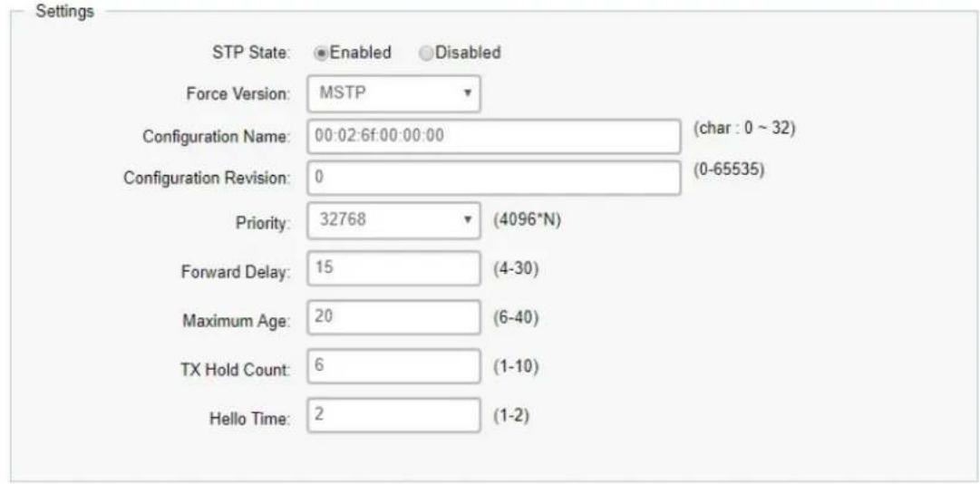
Select whether to Enable or Disable the Spanning Tree function for the Switch. Next, select whether you wish to enable STP, RSTP, or MSTP. Again, please note that only one Spanning tree function can be active at a time.
Global Settings
Apply
| STP State | Select enable or disable the spanning tree operation on the Switch. |
| Force Version | Select the Force Protocol Version parameter for the Switch.RSTP (Rapid Spanning Tree Protocol): IEEE 802.1wMSTP (Multiple Spanning Tree Protocol): IEEE 802.1s |
| Configuration Name | For the switch within the same MST region, must have the same MST configuration name and configuration revision. |
| Configuration Revision | For the switch within the same MST region, must have the same MST configuration name and configuration revision. |
| Priority | Displays the priority for the bridge. When switches are running STP, each is assigned a priority. After exchanging BPDUs, the Switch with the lowest priority value becomes the root bridge. |
| Forward Delay | Displays the Switch Forward Delay Time. This is the time (in seconds) the root switch will wait before changing states (called listening to learning). |
| Maximum Age | Displays the bridge Switch Maximum Age Time. This is the amount of time a bridge waits before sending a configuration message. The default is 20 seconds. |
| Hello Time | Displays the Switch Hello Time. This is the amount of time a bridge remains in a listening and learning state before forwarding packets. The default is 15 seconds. |
Click Apply to save settings.
The Root Bridge serves as an administrative point for all Spanning Tree calculations to determine which redundant links to block in order to prevent network loops. From here, you can view all the information regarding the Root Bridge within the STP.
All other decisions in a spanning tree network, such as ports being blocked and ports being put in a forwarding mode, are made regarding a root bridge. The root bridge is the "root" of the constructed "tree" within a spanning tree network. Thus, the root bridge is the bridge with the lowest bridge ID in the spanning tree network. The bridge ID includes two parts; the bridge priority (2 bytes) and the bridge MAC address (6 bytes). The 802.1d default bridge priority is: 32768. STP devices exchange Bridge Protocol Data Units (BPDUs) periodically. All bridges "listen" for Hello BPDUs (Bridge Protocol Data Units) transmitted from the root bridge. If a bridge does not get a Hello BPDU after a predefined interval (called the Maximum Age), the bridge assumes that the link to the root bridge is down. The bridge then initiates negotiations with other bridges to reconfigure the network to re-establish a valid network topology.
Root Bridge Information
| Bridge Address | 00:02:6f:00:00:00 |
| Root Address: | 00:02:6F:00:00:00 |
| Priority: | 32768 |
| Forward Delay: | 15 (sec) |
| Maximum Age: | 20 (sec) |
| Hello Time: | 1 (sec) |
| Bridge Address | Displays the local bridge MAC address. It will be MAC address of switch. |
| Root Address | Displays the root bridge MAC address. Root in root bridge refers to the base of the spanning tree, which the Switch could be configured for. |
| Priority | Displays the priority for the bridge. When switches are running STP, each is assigned a priority. After exchanging BPDUs, the Switch with the lowest priority value becomes the root bridge. |
| Forward Delay | Displays the Switch Forward Delay Time. This is the time (in seconds) the root switch will wait before changing states (called listening to learning). |
| Maximum Age | Displays the bridge Switch Maximum Age Time. This is the amount of time a bridge waits before sending a configuration message. The default is 20 seconds. |
| Hello Time | Displays the Switch Hello Time. This is the amount of time a bridge remains in a listening and learning state before forwarding packets. The default is 15 seconds. |
RSTP Port Settings
Use the RSTP Ports Settings page to configure and view STA attributes for interfaces when the spanning tree mode is set to RSTP. You may use a different priority or path cost for ports of the same media type to indicate a preferred path or edge port to indicate if the attached device can support fast forwarding or link type to indicate a point-to-point connection or shared-media connection.
| Port | Port or trunked port identifier. |
| Priority | Defines the priority used for this port in the Spanning Tree Algorithm. If the path cost for all ports on a Switch are the same, the port with the highest priority (i.e., lowest value) will be configured as an active link in the Spanning Tree. This makes a port with higher priority less likely to be blocked if the Spanning Tree Algorithm is detecting network loops. When more than one port is assigned the highest priority, the port with lowest numeric identifier will be enabled. The range is from 0 to 240, in steps of 16; and the default is: 128. |
| Path Cost | The Internal Path Cost setting allows you to specify the relative cost of sending spanning tree traffic through the interface to adjacent bridges within a spanning tree region. |
| Designated Root Bridge | Displays the root bridge. It is comprised using the bridge priority and the base MAC address of the bridge. |
| External Root Cost | External root cost is the cost to the root. |
| Edge Port Conf/Oper | Displays the edge port state. |
| P2P MAC Conf/Oper | Modify link type to point-to-point or a shared LAN. |
| Designated Bridge | This is the bridge identifier of the bridge of the designated port. It is made up using the bridge priority and the base MAC address of the bridge. |
| Port Role | Each bridge port that is enabled is assigned a port role within each spanning tree. The port role will be one of the following values: Root Port, Designated Port, Alternate Port, Backup Port, Master Port, or Disabled. |
| Port State | The forwarding state of this port. The state parameters are: Discarding, Learning, Forwarding, or Disabled. |
| Migration Start | When STP migrate between different protocol, basically device will keep (or lock) the using protocol for a while to avoid flapping or toggling. |
Click Apply to update the system settings.
CIST Port Settings
Use the CIST Ports Settings page to configure and view STA attributes for interfaces when the spanning tree mode is set to MSTP. You may use a different priority or path cost for ports of the same media type to indicate a preferred path or edge port to indicate if the attached device can support fast forwarding or link type to indicate a point-to-point connection or shared-media connection.
| CIST Port Settings | |||||||||||||||
| Port | Priority | Internal Path Cost / Oper | External Path Cost / Conf / Oper | Path Cost | Designated Root Bridge | External Root Cost | Registered Root Bridge | Internal Root Cost | Designated Bridge | Edge Port Cost / Open | POP MAC Cost / Open | Port Role | Port State | Migration Start | |
| 120 | 0/-0/- | Yes ☑ | Yes ☑ | ☐ | |||||||||||
| 1 | 128 | 0 / 20000 | 0 / 20000 | 20000 | 0 / 0 /00:00:00:00:00 | 0 | 0 / 0 /00:00:00:00:00 | 0 | 0 / 0 /00:00:00:00:00 | Yes / - | Auto / - | Disabled | Disabled | - | |
| 2 | 128 | 0 / 20000 | 0 / 20000 | 20000 | 0 / 0 /00:05:05:52:55:65 | 300000 | 20672 / 0 /00:13:64:00:15:00 | 0 | 20672 / 0 /00:13:64:00:15:00 | Yes / Yes | Auto / Yes | Designated | Forwarding | - | |
| 3 | 128 | 0 / 20000 | 0 / 20000 | 20000 | 0 / 0 /00:00:00:00:00 | 0 | 0 / 0 /00:00:00:00:00 | 0 | 0 / 0 /00:00:00:00:00 | Yes / - | Auto /- | Disabled | Disabled | - | |
| 4 | 128 | 0 / 20000 | 0 / 20000 | 20000 | 0 / 0 /00:00:00:00:00 | 0 | 0 / 0 /00:00:00:00:00 | 0 | 0 / 0 /00:00:00:00:00 | Yes / - | Auto /+ | Disabled | Disabled | - | |
| 5 | 128 | 0 / 20000 | 0 / 20000 | 20000 | 0 / 0 /00:00:00:00:00 | 0 | 0 / 0 /00:00:00:00:00 | 0 | 0 / 0 /00:00:00:00:00 | Yes / - | Auto / + | Disabled | Disabled | - | |
| 6 | 128 | 0 / 20000 | 0 / 20000 | 20000 | 0 / 0 /00:00:00:00:00 | 0 | 0 / 0 /00:00:00:00:00 | 0 | 0 / 0 /00:00:00:00:00 | Yes / - | Auto / | Disabled | Disabled | - | |
| 7 | 128 | 0 / 20000 | 0 / 20000 | 20000 | 0 / 0 /00:05:05:52:55:65 | 300000 | 20672 / 0 /00:13:64:00:15:00 | 0 | 20672 / 0 /00.13:64:00:15:00 | Yes / Yes | Auto / Yes | Designated | Forwarding | - | |
| 8 | 128 | 0 / 20000 | 0 / 20000 | 20000 | 0 / 0 /00:05:05:52:55:65 | 300000 | 20672 / 0 /00:13:64:00:15:00 | 0 | 20672 / 0 /00 :13:64:00:15:00 | Yes / Yes | Auto / Yes | Designated | Forwarding | - | |
| 9 | 128 | 0 / 20000 | 0 / 20000 | 20000 | 0 / 0 /00:05:05:52:55:65 | 300000 | 20672 / 0 /00:13:64:00:15:00 | 0 | 20672 / 0 /00 .13:64:00:15:00 | Yes / Yes | Auto / Yes | Designated | Forwarding | - | |
| 10 | 128 | 0 / 20000 | 0 / 20000 | 20000 | 0 / 0 /00:05:05:52:55:65 | 280000 | 32768 / 0 /88 DC 96 :1D 8A :05 | 0 | 32768 / 0 /88 DC 96 :1D 8A :05 | Yes / No | Auto / Yes | Root | Forwarding | - | |
| 11 | 128 | 0 / 20000 | 0 / 20000 | 20000 | 0 / 0 /00:00:00:00:00 | 0 | 0 / 0 /00:00:00:00:00 | 0 | 0 / 0 /00:00:00:00:00 | Yes / - | Auto/ - | Disabled | Disabled | - | |
| 12 | 128 | 0 / 20000 | 0 / 20000 | 20000 | 0 / 0 /00:00:00:00:00 | 0 | 0 / 0 /00:00:00:00:00 | 0 | 0 / 0 /00:00:00:00:00 | Yes / - | Auto / -- | Disabled | Disabled | - | |
| trunk1 | 128 | 0 / 20000 | 0 / 20000 | 20000 | 3 / 0 /00:00:00:00:00 | 0 | 3 / 0 /00:00:00:00:00 | 0 | 0 / 0 /00:00:00:00:00 | Yes / - | Auto / - | Disabled | Disabled | - | |
| trunk2 | 128 | 0 / 20000 | 0 / 20000 | 20000 | 0 / 0 /00:00:00:00:00 | 0 | 9 / 0 /00:00:00:00:00 | 0 | 9 / 0 /00:00:00:00:00 | Yes / - | Auto / - | Disabled | Disabled | - | |
| trunk3 | 128 | 0 / 20000 | 0 / 20000 | 20000 | 5 / 0 /00:00:00:00:00 | 0 | 5 / 0 /00:00:00:00:00 | 0 | 5 / 0 /00:00:00:00:00 | Yes / - | Auto / - | Disabled | Disabled | - | |
| trunk4 | 128 | 0 / 20000 | 0 / 20000 | 20000 | 0 / 0 /00:00:00:00:00 | 0 | 9 / 0 /00:00:00:00:00 | 0 | 9 / 0 /00:00:00:00:00 | Yes / - | Auto / -- | Disabled | Disabled | - | |
| trunk5 | 128 | 0 / 20000 | 0 / 20000 | 20000 | 3 / 0 /00:00:00:00:00 | 0 | 9 / 0 /00:00:00:00:00 | 0 | 9 / 0 /00:00:00:00:00 | Yes / - | Auto / -- | Disabled | Disabled | - | |
| Port | Port or trunked port identifier. |
| Priority Defines the | priority used for this port in the Spanning Tree Algorithm. If the path costs for all ports on a Switch are the same, the port with the highest priority (i.e., lowest value) will be configured as an active link in the Spanning Tree. This makes a port with higher priority less likely to be blocked if the Spanning Tree Algorithm is detecting network loops. When more than one port is assigned the highest priority, the port with lowest numeric identifier will be enabled. The range is from 0 to 240, in steps of 16; and the default is: 128. |
| Path Cost | The Internal Path Cost setting allows you to specify the relative cost of sending spanning tree traffic through the interface to adjacent bridges within a spanning tree region. |
| Designated Root Bridge | Displays the root bridge for the CST. It is comprised using the bridge priority and the base MAC address of the bridge. |
| External Root Cost | External root cost is the cost to the CIST root. |
| Regional Root Bridge | This is the bridge identifier of the CST regional root. It is made up using the bridge priority and the base MAC address of the bridge. |
| Designated Bridge | This is the bridge identifier of the bridge of the designated port. It is made up using the bridge priority and the base MAC address of the bridge. |
| bridge. | |
| Edge Port Conf/Oper | Displays the edge port state. |
| P2P MAC Conf/Oper | Modify link type to point-to-point or a shared LAN. |
| Port Role | Each MST bridge port that is enabled is assigned a port role within each spanning tree. The port role will be one of the following values: Root Port, Designated Port, Alternate Port, Backup Port, Master Port, or Disabled. |
| Port State | The forwarding state of this port. The state parameters are: Discarding, Learning, Forwarding, or Disabled. |
| Migration Start | When STP migrate between different protocol, basically device will keep (or lock) the using protocol for a while to avoid flapping or toggling. |
Click Apply to update the system settings.
MST Instance Settings
Multiple Spanning Tree Protocol (MSTP) enables the grouping of multiple VLANs with the same topology requirements into one Multiple Spanning Tree Instance (MSTI). MSTP then builds an Internal Spanning Tree (IST) for the region containing commonly configured MSTP bridges. Instances are not supported in STP or RSTP. Instead, they have the same spanning tree in common within the VLAN. MSTP provides the capability to logically divide a Layer 2 network into regions. Every region can contain multiple instances of spanning trees. In MSTP, all of the interconnected bridges that have the same MSTP configuration comprise an MST region.
A Common Spanning Tree (CST) interconnects all adjacent MST regions and acts as a virtual bridge node for communications between STP or RSTP nodes in the global network. MSTP connects all bridges and LAN segments with a single Common and Internal Spanning Tree (CIST). The CIST is formed as a result of the running spanning tree algorithm between switches that support STP, RSTP, and MSTP protocols. Once you specify the VLANs you wish to include in a Multiple Spanning Tree Instance (MSTI), the protocol will automatically build an MSTI tree to maintain connectivity among each of the VLANs. MSTP maintains contact with the global network because each instance is treated as an RSTP node in the Common Spanning Tree (CST).
Click the Edit button to configure the MST settings. Next, enter information for the VLAN List and choose the priority you wish to use from the drop-down list.
MST Instance Settings
| MST ID | VLAN List | Priority | Regional Root Bridge | Internal Root Cost | Designated Bridge | Root Port |
| 1-15 | 1-4094 | 32768 |
| MST ID | Displays the ID of the MST group that is created. A maximum of 15 groups can be set for the Switch. |
| VLAN List | Enter the VLAN ID range from for the configured VLANs to associate with the MST ID. The VLAN ID number range is from 1 to 4094. |
| Priority | Select the bridge priority value for the MST. When Switches or bridges are running STP, each is assigned a priority. After exchanging BPDUs, the Switch with the lowest priority value becomes the root bridge. The default value is: 32768. The range is from 0 to 61440. The bridge priority is a multiple of 4096. |
| Regional Root Bridge | This is the bridge identifier of the CST regional root. It is made up using the bridge priority and the base MAC address of the bridge. |
| Internal Root Cost | Displays the path cost to the designated root for the MST instance. |
| Designated Bridge | Displays the bridge identifier of the bridge with the designated port. It is made up using the bridge priority and the base MAC address of the bridge. |
| Root Port | Displays the port that accesses the designated root for MST instance. |
Click the Apply button √ to accept the changes or the Cancel button ✗ to discard them.
MST Port Settings
This page displays the current MSTI configuration information for the Switch. From here you can update the port configuration for an MSTI ID. If a loop occurs, the MSTP function will use the port priority to select an interface to put into the forwarding state. Set a higher priority value for ports you wish to be selected for forwarding first. In instances where the priority value is identical, the MSTP function will implement the lowest MAC address into the forwarding state and other interfaces will be blocked. Note that a lower priority values mean higher priorities for forwarding packets.
| MST Port Settings | |||||||||
| MST ID | Port | Priority | Internal Path Cost Conf / Oper | Regional Root Bridge | Internal Root Cost | Designated Bridge | Port Role | Port State | |
| □ | 1 | √ | 128 | 0 | |||||
| □ | 1 | 1 | 128 | 0/20000 | -/- | -- | -/- | -- | -- |
| □ | 1 | 2 | 128 | 0/20000 | -/- | -- | -/- | -- | -- |
| □ | 1 | 3 | 128 | 0/20000 | -/- | -- | -/- | -- | -- |
| □ | 1 | 4 | 128 | 0/20000 | -/- | -- | -/- | -- | -- |
| □ | 1 | 5 | 128 | 0/20000 | -/- | -- | -/- | -- | -- |
| □ | 1 | 6 | 128 | 0/20000 | -/- | -- | -/- | -- | -- |
| □ | 1 | 7 | 128 | 0/20000 | -/- | -- | -/- | -- | -- |
| □ | 1 | 8 | 128 | 0/20000 | -/- | -- | -/- | -- | -- |
| □ | 1 | 9 | 128 | 0/20000 | -/- | -- | -/- | -- | -- |
| □ | 1 | 10 | 128 | 0/20000 | -/- | -- | -/- | -- | -- |
| □ | 1 | 11 | 128 | 0/20000 | -/- | -- | -/- | -- | -- |
| □ | 1 | 12 | 128 | 0/20000 | -/- | -- | -/- | -- | -- |
| □ | 1 | trunk1 | 128 | 0/20000 | -/- | -- | -/- | -- | -- |
| □ | 1 | trunk2 | 128 | 0/20000 | -/- | -- | -/- | -- | -- |
| □ | 1 | trunk3 | 128 | 0/20000 | -/- | -- | -/- | -- | -- |
| □ | 1 | trunk4 | 128 | 0/20000 | -/- | -- | -/- | -- | -- |
| □ | 1 | trunk5 | 128 | 0/20000 | -/- | -- | -/- | -- | -- |
| □ | 1 | trunk6 | 128 | 0/20000 | -/- | -- | -/- | -- | -- |
| □ | 1 | trunk7 | 128 | 0/20000 | -/- | -- | -/- | -- | -- |
| □ | 1 | trunk8 | 128 | 0/20000 | -/- | -- | -/- | -- | -- |
| MST ID | Displays the ID of the MST group that is created. A maximum of 15 groups can be set for the Switch. |
| Port | Displays port or trunked port ID. |
| Priority | Select the bridge priority value for the MST. When switches or bridges are running STP, each is assigned a priority. After exchanging BPDUs, the Switch with the lowest priority value becomes the root bridge. The bridge priority is a multiple of 4096. If you specify a priority that is not a multiple of 4096, the priority is automatically set to the next lowest priority that is a multiple of 4096. For example, if you set the priority to any value from 0 through 4095, the priority is set to 0. The default priority is: 32768. The valid range is from 0 to 61440. |
| Internal Path Cost Conf | The Internal Path Cost setting allows you to specify the relative cost of sending spanning tree traffic through the interface to adjacent bridges within a spanning tree region. |
| Internal Path Cost Oper | Displays the operation cost of the path from this bridge to the root bridge. |
| Regional Root Bridge | This is the bridge identifier of the CST regional root. It is made up using the bridge priority and the base MAC address of the bridge. |
| Internal Root Cost | Displays the path cost to the designated root for the selected MST instance. |
| Designated Bridge | Displays the bridge identifier of the bridge for the designated port. It is made up using the bridge priority and the base MAC address of the bridge. |
| Internal Port Cost | This parameter is set to represent the relative cost of forwarding packets to specified ports when an interface is selected within an STP instance. Selecting this parameter with a value in the range of 1 to 200000000 will set the quickest route when a loop occurs. A lower internal cost represents a quicker transmission. Selecting 0 (zero) for this parameter will set the quickest optimal route automatically for an interface. |
| Port Role: | Each MST bridge port that is enabled is assigned a port role for each spanning tree. The port role is one of the following values: Root, Designated, Alternate, Backup, Master, or Disabled. |
| Port State | Displays the state of the selected port. |
| Edge Port Ope | Displays the operating edge port state. |
| P2P MAC Conf | Displays the P2P MAC state. |
| P2P MAC Oper | Displays the operating P2P MAC state. |
| Port Role | Displays the port role. Shows each MST bridge port that is assigned a port role for each spanning tree. |
| Port State | Indicates the current STP state of a port. If enabled, the port state determines what forwarding action is taken regarding traffic. The possible port states are:Disabled:STP is disabled on the port. The port forwards traffic while learning MAC addresses.Blocking:The port is blocked and cannot be used to forward traffic or learn MAC addresses.Listening:The port is in listening mode. The port cannot forward traffic or learn MAC addresses in this state.Learning:The port is in learning mode. The port cannot forward traffic. However, it can learn new MAC addresses.Forwarding:The port is in forwarding mode. The port can forward traffic and learn new MAC addresses in this state. |
Click Apply to update the system settings.
STP Port Statistics
Display STP related packet counters on each port.
STP Port Statistics
| Port | RX BPDU | TX BPDU | Invalid BPDU | |
| 1 | 0 | 0 | 0 | |
| 2 | 948 | 3 | 0 | |
| 3 | 0 | 3210 | 0 | |
| 4 | 0 | 0 | 0 | |
| 5 | 0 | 0 | 0 | |
| 6 | 0 | 0 | 0 | |
| 7 | 0 | 0 | 0 | |
| 8 | 0 | 0 | 0 | |
| 9 | 0 | 0 | 0 | |
| 10 | 0 | 0 | 0 | |
| 11 | 0 | 0 | 0 | |
| 12 | 0 | 0 | 0 | |
| trunk1 | 0 | 0 | 0 | |
| trunk2 | 0 | 0 | 0 | |
| trunk3 | 0 | 0 | 0 | |
| trunk4 | 0 | 0 | 0 | |
| trunk5 | 0 | 0 | 0 | |
| trunk6 | 0 | 0 | 0 | |
| trunk7 | 0 | 0 | 0 | |
| trunk8 | 0 | 0 | 0 | |
Clear
Click Clear to clear STP packet counters on specific ports.
LBD
Loopback Detection (LBD) can be used to detect loops by transmit loop protocol packets. Ports will send out loop protocol packets, once the same packet is received, the port will be shut down to prevent loop.
LBD Global
LoopBack Detection

| State | All ports send loop packets out if Enabled is set, and when the same packet is received, the port will be shut down to prevent loop. |
Click Apply to update the system settings.
LBD Port Status
Port Status
| Port | state |
| 1 | Normal |
| 2 | Normal |
| 3 | Normal |
| 4 | Normal |
| 5 | Normal |
| 6 | Normal |
| 7 | Normal |
| 8 | Normal |
| 9 | Normal |
| 10 | Normal |
| 11 | Normal |
| 12 | Normal |
| Port | Port index of physical port. |
| state | Displays the state of per port LBD status. |
MAC Address Table
The MAC address table contains address information that the Switch uses to forward traffic between the inbound and outbound ports. All MAC addresses in the address table are associated with one or more ports. When the Switch receives traffic on a port, it searches the Ethernet switching table for the MAC address of the destination. If the MAC address is not found, the traffic is flooded out all of the other ports associated with the VLAN. All of the MAC address that the Switch learns by monitoring traffic are stored in the dynamic address. A static address allows you to manually enter a MAC address to configure a specific port and VLAN.
Static MAC Address
The address table lists the destination MAC address, the associated VLAN ID, and port number associated with the address. When you specify a static MAC address, you set the MAC address to a VLAN and a port; thus it makes an entry into its forwarding table. These entries are then used to forward packets through the Switch. Static MAC addresses along with the Switch's port security allow only devices in the MAC address table on a port to access the Switch.

| Index | Displays the index for the static MAC address table. |
| Port | Select the port where the MAC address entered in the previous field will be automatically forwarded. |
| VID | Enter the VLAN ID on which the IGMP Snooping querier is administratively enabled and for which the VLAN exists in the VLAN database. |
| MAC Address | Enter a unicast MAC address for which the switch has forwarding or filtering information. |
Click the Apply button √ to accept the changes or the Cancel button ✗ to discard them.
Dynamic MAC Address
The Switch will automatically learn the device's MAC address and store it to the dynamic MAC address table. If there is no packet received from the device within the aging time, the Switch adopts an aging mechanism for updating the tables from which MAC address entries will be removed from related network devices. The dynamic MAC address table shows the MAC addresses and their associated VLANs learned on the selected port.
Dynamic MAC Address
| Index | Port | VID | MAC Address |
| 1 | 3 | 1 | 84:16:f9:00:46:30 |
| Move to Static | Administrator can move Dynamic MAC address entry as Static MAC address entry. Static MAC address will not take effect by timeout timer in global settings. |
| Index | Displays the index for the dynamic MAC address table. |
| Port | Select the port to which the entry refers. |
| VID | Displays the VLAN ID corresponding to the MAC address. |
| MAC Address | Displays the MAC addresses that the Switch learned from a specific port. |
Click the button ⏻ to move dynamic MAC address to static MAC address.
Search MAC Address
To search specific MAC address from whole MAC address table.
Search MAC Address
| Searchings |
| MAC Address: 84.16.f9:00:46:30 |

| Index | Port | VID | MAC Address | Type |
| 1 | 3 | 1 | 84:16:F9:00:46:30 | Dynamic |
| Index | Displays the index for the dynamic MAC address table. |
| Port | Select the port to which the entry refers. |
| VID | Displays the VLAN ID corresponding to the MAC address. |
| MAC Address | Displays the MAC addresses that the Switch learned from a specific port. |
| Type | Displays the MAC addresses entry is static or dynamic. |
Click Search to search specific MAC address from MAC address table.
MAC Aging Settings
To set aging time of whole MAC address table.
MAC Aging Settings

| MAC Aging Time | Administrator can move Dynamic MAC address entry as Static MAC address entry. Static MAC address will not take effect by timeout timer in global settings. Default value is 5 minutes. |
Click Apply to update the system settings.
LLDP
Link Layer Discovery Protocol (LLDP) is the IEEE 802.1AB standard for Switches to advertise their identity, major capabilities, and neighbors on the 802 LAN. LLDP allows users to view the discovered information to identify system topology and detect faulty configurations on the LAN. LLDP is essentially a neighbor discovery protocol that uses Ethernet connectivity to advertise information to devices on the same LAN and store information about the network. The information transmitted in LLDP advertisements flow in one direction only; from one device to its neighbors. This information allows the device to quickly identify a variety of other devices, resulting in a LAN that interoperates smoothly and efficiently.
LLDP transmits information as packets called LLDP Data Units (LLDPDUs). A single LLDPDU is transmitted within a single 802.3 Ethernet frame. A basic LLDPDU consists of a set of Type-Length-Value elements (TLV), each of which contains information about the device. A single LLDPDU contains multiple TLVs. TLVs are short information elements that communicate complex data. Each TLV advertises a single type of information.
Global Settings
Global Settings
Settings
Apply
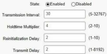
Select whether to enable or disable the LLDP feature on the Switch. Next, enter the Transmission Interval, Holdtime Multiplier, Reinitialization Delay parameter, and the Transmit Delay parameter. When finished, click Apply to update the system settings.
| State | Select Enabled or Disabled to activate LLDP for the Switch. |
| Transmission Interval | Enter the interval at which LLDP advertisement updates are sent. The default value is 30. The range is from 5 to 32768. |
| Holdtime Multiplier | Enter the amount of time that LLDP packets are held before packets are discarded and measured in multiples of the Advertised Interval. The default is 4. The range is from 2 to 10. |
| Reinitialization Delay | Enter the amount of time of delay before reinitializing LLDP. The default is 2. The range is from 1 to 10. |
| Transmit Delay | Enter the amount of time that passes between successive LLDP frame transmissions. The default is 2 seconds. The range is from 1 to 8191 seconds. |
Local Device
LLDP devices must support chassis and port ID advertisement, as well as the system name, system ID, system description, and system capability advertisements. Here, you can view detailed LLDP information for the Switch.
Local Device
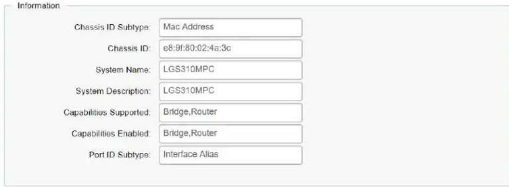
| Chassis ID Subtype Displays the chassis ID type. | |
| Chassis ID Displays the chassis ID of the device transmitting the LLDP frame. | |
| System Name Displays the administratively assigned device name. | |
| System Description Describes the device. | |
| Capabilities Supported Describes the device functions. | |
| Capabilities Enabled Describes the device functions. | |
| Port ID Subtype Displays the port ID type. |
Remote Device
LLDP devices must support chassis and port ID advertisement, as well as the system name, system ID, system description, and system capability advertisements. From here you can viewing detailed LLDP Information for the remote device.
| Port | Chassis ID Subtype | ChassisID | Port ID Subtype | Remote ID | System Name | Time To Line | Auto-Negotiation Supported | Auto-Negotiation Enabled | Auto-Negotiation Advertised Capabilities | Operational MAU Type | 802.3 Maximum Frame Size | 802.3 Link Aggregation Capability | 802.3 Link Aggregation Status | 802.3 Link Aggregation PortID |
| 2 | MAC address | 01 02 4F FE 94 46 | Interfico name | eth0 | James_kst_EYS310AP | 72 | Disabled | Disabled | 0 | 0 | ||||
| 10 | MAC address | BE DC 96 1D 0A 05 | Locally assigned | g3 | EGS7252FP | 114 | Enabled | Enabled | 10BASE-T half duplex, 10BASE-T full duplex, 100BASE-TX full duplex, 100BASE-TX full duplex, 100BASE-T full duplex | 100BASE-T full duplex mode | 1522 | Capable of being aggregated | Net currently in aggregation | 0 |
| Port | Displays the port. |
| Chassis ID Subtype | Displays the chassis ID type. |
| Chassis ID | Displays the chassis ID of the device that is transmitting the LLDP frame. |
| Port ID Subtype | Displays the port ID type. |
| Remote ID | Displays the remote ID. |
| System Name | Displays the administratively assigned device name. |
| Time to Live | Displays the time to live. |
| Auto-Negotiation Supported | Displays state for the auto-negotiation supported. |
| Auto-Negotiation Enabled | Displays state for the auto-negotiation enabled. |
| Auto-Negotiation Advertised Capabilities | Displays the type of auto-negotiation advertised capabilities. |
| Operational MAU Type | Displays the type of MAU. |
| 802.3 Maximum Frame Size | Displays the maximum size of 802.3 maximum frame. |
| 802.3 Link Aggregation Capabilities | Displays the 802.3 Link Aggregation capabilities. |
| 802.3 Link Aggregation Status | Displays the status of 802.3 Link Aggregation. |
| 802.3 Link Aggregation Port ID | Displays the port ID of 802.3 Link Aggregation. |
IGMP Snooping
Internet Group Management Protocol (IGMP) Snooping allows a Switch to forward multicast traffic intelligently. Multicasting is used to support real-time applications such as video conferencing or streaming audio. A multicast server does not have to establish a separate connection with each client. It merely broadcasts its service to the network, and any host that wishes to receive the multicast register with their local multicast Switch.
A multicast group is a group of end nodes that want to receive multicast packets from a multicast application. After joining a multicast group, a host node must continue to periodically issue reports to remain a member. Any multicast packets belonging to that multicast group are then forwarded by the Switch from the port.
A Switch supporting IGMP Snooping can passively snoop on IGMP Query, Report, and Leave packets transferred between IP Multicast switches and IP Multicast hosts to determine the IP Multicast group membership. IGMP Snooping checks IGMP packets passing through the network and configures multicasting accordingly. Based on the IGMP query and report messages, the Switch forwards traffic only to the ports that request the multicast traffic. It enables the Switch to forward packets of multicast groups to those ports that have validated host nodes. The Switch can also limit flooding of traffic to IGMP designated ports. This improves network performance by restricting the multicast packets only to switch ports where host nodes are located. IGMP Snooping significantly reduces overall Multicast traffic passing through your Switch. Without IGMP Snooping, Multicast traffic is treated in the same manner as a broadcast transmission, which forwards packets to all ports on the network.
| IGMPv1 | Defined in RFC 1112. An explicit join message is sent to the Switch, but a timeout is used to determine when hosts leave a group. |
| IGMPv2 | Defined in RFC 2236. Adds an explicit leave message to the join message so thatSwitch can more easily determine when a group has no interested listeners on a LAN. |
| IGMPv3 | Defined in RFC 3376. Support for a single source of content for a multicast group. |
Global Settings
Click to enable or disable the IGMP Snooping feature for the Switch. Next, select whether you wish to use V2 or V3. Finally, select whether you wish to enable or disable the Report Suppression feature for the Switch.
Global Settings

Apply
| Status | Select to enable or disable IGMP Snooping on the Switch. The Switch snoops all IGMP packets it receives to determine which segments should receive packets directed to the group address when enabled. The default setting is: Disabled. |
| Mode | IP mode: Group List will be changed to IP mode, and switch will learn group by igmp join packet's IP address, for example, 238.255.0.1 and 239.255.0.1 are different groups.MAC mode: Group List will be changed to mac mode, and switch will learn group by igmp join packet's mac address, for example, 238.255.0.1 and 239.255.0.1 are the same group. |
| Report Suppression | Select whether Report Suppression is Enabled or Disabled for IGMP Snooping. The Report Suppression feature limits the amount of membership reports the member sends to multicast capable routers. |
Click Apply to update the system settings.
VLAN Settings
Use the IGMP Snooping VLAN Settings to configure IGMP Snooping settings for VLANs on the system.
The Switch performs IGMP Snooping on VLANs that send IGMP packets. You can specify the VLANs that IGMP Snooping should be performed on. Choose from the drop-down box whether to enable or disable IGMP Snooping. Next, choose to enable or disable Fast Leave for the VLAN ID.
VLAN Settings
| VLAN ID | IGMP Snooping Status | Version | Fast Leave |
| 1 | Disabled | v1 | Disabled |
| VLAN ID Displays the | VLAN ID. |
| IGMP Snooping Status | Enables or disables the IGMP Snooping feature for the specified VLAN ID. |
| Version | This value will affect the igmp packets type that encode and send from switch, by the way, this value is the same as Querier Version in the “Querier Settings” page. |
| Fast Leave | Enables or disables the IGMP Snooping Fast Leave for the specified VLANID. Enabling this feature allows the Switch to immediately remove the Layer 2 LAN port from its forwarding table entry upon receiving an IGMP leave message without first sending out IGMPgroup-specific (GS) queries to the port. |
Click the Apply button √ to accept the changes or the Cancel button ✗ to discard them.
If Fast Leave is not used, a multicast querier will send a GS-query message when an IGMPv2/v3 group leave message is received. The querier stops forwarding traffic for that group only if no host replies to the query within the specified timeout period. If Fast Leave is enabled, the Switch assumes that only one host is connected to the port. Therefore, Fast Leave should only be enabled on a port if it is connected to only one IGMP-enabled device.
Fast Leave is supported only with IGMPv2 or IGMPv3 Snooping when IGMP Snooping is enabled. Fast Leave does not apply to a port if the Switch has learned that a multicast querier is attached to it.
Fast Leave can improve bandwidth usage for a network which frequently experiences many IGMP host add and leave requests.
Querier Settings
IGMP Snooping requires that one central Switch to periodically query all end devices on the network to announce their multicast memberships and this central device is the IGMP querier. The snooping Switch sends out periodic queries with a time interval equal to the configured querier query interval. The IGMP query keeps the Switch updated with the current multicast group membership information. If the Switch does not receive the updated membership information, then it will stop forwarding multicasts to specified VLANs.
| Querier Settings | |||||||||||||
| VLAN ID | Querier State | Quarier Version | Quarier Status | Querier IP | Robustness | Interval | Oper Interval | Max Response Interval | Oper Max Response Interval | Last Member Query Counter | Oper Last Member Query Counter | Last Member Query Interval | Oper Last Member Query Interval |
| 1 | Disabled | v2 | Non-Querier | — | 2 | 125 | 125 | 10 | 10 | 2 | 2 | 1 | 1 |
| VLAN ID Displays the VLAN ID. | |
| Querier State | Select whether to enable or disable the IGMP querier state for the specified VLAN ID.A querier can periodically ask their hosts if they wish to receive multicast traffic. The querier feature will check whether hosts wish to receive multicast traffic when enabled. An elected querier will assume the role of querying the LAN for group members, and then propagates the service requests on to any upstream multicast Switch to ensure that it will continue to receive the multicast service. This feature is only supported for IGMPv1 and v2 snooping. |
| Querier Version | Enter the version of IGMP packet that will be sent by this port. If an IGMP packet received by the port has a version higher than the specified version, this packet will be dropped. |
| Querier Status | The role of the switch in our network topology, querier or nonquerier |
| Querier IP | The IP adderss of the querier in our network topology, if switch is querier, this value will be switch IP address. |
| Interval | Enter the amount of time in seconds between general query |
| transmissions. The default is 125 seconds. | |
| Max Response Interval | Enter the maximum response time used in the queries that are sent by the snooping querier. The default is 10 seconds. |
| Startup Query Counter | The number of general query that be sent by switch, when the switch become the querier. |
| Startup Query Interval | The interval of general query that be sent by switch, when the switch become the querier. |
Click the Apply button √ to accept the changes or the Cancel button ✗ to discard them.
Group List
The Group List displays VLAN ID, group IP address, and members port in the IGMP Snooping list.
| Group List | ||
| VLAN ID | Group IP Address | Member Ports |
Router Settings
The Router Settings shows the learned multicast router attached port if the port is active and a member of the VLAN. Select the VLAN ID you would like to configure and enter the Static and Forbidden ports for the specified VLAN IDs. All IGMP packets snooped by the Switch will be forwarded to the multicast router reachable from the port.
Router Settings
| VLAN ID | Dynamic Port List | Static Port List | Forbidden Port List |
| 1 |
| VLAN ID Displays the VLAN ID. | |
| Dynamic Port List Displays | router ports that have been dynamically configured. |
| Forbidden Port List | Designates a range of ports as being disconnected to multicast-enabled routers. Ensures that the forbidden router port will not propagate routing packets out. |
| Static Port list | Designates a range of ports as being connected to multicast-enabled routers. Ensures that all the packets will reach the multicast-enabled router. |
Click the Apply button √ to accept the changes or the Cancel button ✗ to discard them.
MLD Snooping
Multicast Listener Discovery (MLD) Snooping operates on the IPv6 traffic level for discovering multicast listeners on a directly attached port and performs a similar function to IGMP Snooping for IPv4. MLD snooping allows the Switch to examine MLD packets and make forwarding decisions based on content. MLD Snooping limits IPv6 multicast traffic by dynamically configuring the Switch port so that multicast traffic is forwarded only to those ports that wish to receive it. This reduces the flooding of IPv6 multicast packets in the specified VLANs. Both IGMP and MLD Snooping can be active at the same time.
Global Settings
Global Settings
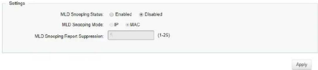
| Status | Select to enable or disable MLD Snooping on the Switch. The Switch snoops all MLD packets it receives to determine which segments should receive packets directed to the group address when enabled. The default setting is: Disabled. |
| Mode | IP mode: Group List will be changed to IP mode, and switch will learn group by MLD join packet's IP address.MAC mode: Group List will be changed to mac mode, and switch will learn group by MLD join packet's mac address. |
| Report Suppression | Select whether Report Suppression is Enabled or Disabled for MLD Snooping. The Report Suppression feature limits the amount of membership reports the member sends to multicast capable routers. |
Click Apply to update the system settings.
VLAN Settings
If the Fast Leave feature is not used, a multicast querier will send a GS-query message when an MLD group leave message is received. The querier stops forwarding traffic for that group only if no host replies to the query within the specified timeout period. If Fast Leave is enabled, the Switch assumes that only one host is connected to the port. Therefore, Fast Leave should only be enabled on a port if it is connected to only one MLD-enabled device.
VLAN Settings

Fast Leave does not apply to a port if the Switch has learned that a multicast querier is attached to it. Fast Leave can improve bandwidth usage for a network which frequently experiences many MLD host add and leave requests.
| VLAN ID Displays the | VLAN ID. |
| MLD Snooping Status | Select to enable or disable the MLD snooping feature for the specified VLAN ID. |
| Version | This value will affect the MLD packets type that encode and send from switch, by the way, this value is the same as Querier Version in the “Querier Settings” page. |
| Fast Leave | Enables or disables the MLD snooping Fast Leave feature for the specified VLAN ID. Enabling this feature allows the Switch to immediately remove the Layer 2 LAN port from its forwarding table entry upon receiving an MLD leave message without first sending out an MLD group-specific (GS) query to the port. |
Select from the drop-down list whether to enable or disable MLD Snooping. Next, select to enable or disable Fast Leave for the specified VLAN ID.
Click the Apply button √ to accept the changes or the Cancel button ✗ to discard them.
Querier Settings
IGMP Snooping requires that one central Switch to periodically query all end devices on the network to announce their multicast memberships and this central device is the IGMP querier. The snooping Switch sends out periodic queries with a time interval equal to the configured querier query interval. The IGMP query keeps the Switch updated with the current multicast group membership information. If the Switch does not receive the updated membership information, then it will stop forwarding multicasts to specified VLANs.
Querier Settings
| VLAN ID | Querier State | Querier Version | Querier Status | Interval |
| 1 | Disabled | v2 | Non-Querier | 0 |
| VLAN ID Displays the VLAN ID. | |
| Querier State | Select whether to enable or disable the MLD querier state for the specified VLAN ID.A querier can periodically ask their hosts if they wish to receive multicast traffic. The querier feature will check whether hosts wish to receive multicast traffic when enabled. An elected querier will assume the role of querying the LAN for group members, and then propagates the service requests on to any upstream multicast Switch to ensure that it will continue to receive the multicast service. This feature is only supported for IGMPv1 and v2 snooping. |
| Querier Version | Enter the version of MLD packet that will be sent by this port. If an IGMP packet received by the port has a version higher than the specified version, this packet will be dropped. |
| Querier Status | The role of the switch in our network topology, querier or nonquerier |
| Interval | Enter the amount of time in seconds between general query transmissions. The default is 125 seconds. |
Group List
The Group List displays the VLAN ID, IPv6 address, and members port in the MLD Snooping List.
Group List
VLAN ID IPv6 Address Member Ports
Router Settings
The Router Settings feature shows the learned multicast router attached port if the port is active and a member of the VLAN. Select the VLAN ID you would like to configure and enter the static and forbidden ports for the specified VLAN IDs that are utilizing MLD Snooping. All MLD packets snooped by the Switch will be forwarded to the multicast router reachable from the port.
Router Settings
| VLAN ID | Dynamic Port List | Static Port List | Forbidden Port List |
| 1 |
| VLAN ID Dis | plays the VLAN ID. |
| Dynamic Port List | Displays router ports that have been dynamically configured. |
| Forbidden Port List | Designates a range of ports as being disconnected to multicast-enabled routers. Ensure that the forbidden router port will not propagate routing packets out. |
| Static Port List | Designates a range of ports as being connected to multicast-enabled routers. Ensure that all the packets will reach the multicast-enabled router. |
Click the Apply button √ to accept the changes or the Cancel button ✗ to discard them.
Multicast Filtering
When multicast filtering is enabled, unknown multicast packets (did not learn by IGMP and MLD) will be dropped, and the multicast packets already learnt by IGMP/MLD will forward as multicast forwarding table.
When multicast filtering is disabled, unknown multicast packets (did not learn by IGMP and MLD) will be flooded, and the multicast packets already learnt by IGMP/MLD will forward as multicast forwarding table.
Multicast Filtering

Apply
| State | To set multicast filtering as enabled or disabled. Default is disabled. |
Click Apply to update the system settings.
Jumbo Frame
Ethernet has used the 1500 byte frame size since its inception. Jumbo frames are network-layer PDUs that have a size much larger than the typical 1500 byte Ethernet Maximum Transmission Unit (MTU) size. Jumbo frames extend Ethernet to 10240 bytes, making them large enough to carry an 10 KB application datagram plus packet header overhead. If you intend to leave the local area network at high speeds, the dynamics of TCP will require you to use large frame sizes.
The switch supports a jumbo frame size of up to 10240 bytes. Jumbo frames need to be configured to work on the ingress and egress port of each device along the end-to-end transmission path.
Furthermore, all devices in the network must also be consistent on the maximum jumbo frame size, so it is important to do a thorough investigation of all your devices in the communication paths to validate their settings.
Jumbo Frame
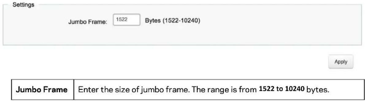
Note: With different platforms, the max jumbo frame maybe different.
Click Apply to update the system settings.
VLAN
A Virtual LAN (VLAN) is a group of ports that form a logical Ethernet segment on a Layer 2 Switch which provides better administration, security, and management of multicast traffic. A VLAN is a network topology configured according to a logical scheme rather than a physical layout. When you use a VLAN, users can be grouped by logical function instead of physical location. All ports that frequently communicate with each other are assigned to the same VLAN, regardless of where they are physically on the network. VLANs let you logically segment your network into different broadcast domains so that you can group ports with related functions into their own separate, logical LAN segments on the same Switch. This allows broadcast packets to be forwarded only between ports within the VLAN which can avoid broadcast packets being sent to all the ports on a single Switch. A VLAN also increases network performance by limiting broadcasts to a smaller and more manageable logical broadcast domain. VLANs also improve security by limiting traffic to specific broadcast domains.
802.1Q
Each VLAN in a network has an associated VLAN ID, which appears in the IEEE 802.1Q tag in the Layer 2 header of packets transmitted on a VLAN. The IEEE 802.1Q specification establishes a standard method for tagging Ethernet frames with VLAN membership information. The key for IEEE 802.1Q to perform its functions is in its tags. 802.1Q-compliant Switch ports can be configured to transmit tagged or untagged frames. A tag field containing VLAN information can be inserted into an Ethernet frame. When using 802.1Q VLAN configuration, you configure ports to be a part of a VLAN group. When a port receives data tagged for a VLAN group, the data is discarded unless the port is a member of the VLAN group.
802.1Q
| VID | Name | Tagged Port | Untagged Port | + Add |
| 1 | default | 1-28,11-t8 | ||
| 25 | vid25 | 25 | ||
| 26 | vid26 | 26 |
| VID | Displays the VLAN ID for which the network policy is defined. The range of the VLAN ID is from 1 to 4094. |
| Name | Enter the VLAN name. You can use up to 32 alphanumeric characters. |
| Tagged Port | Frames transmitted from this port are tagged with the VLAN ID. |
| Untagged Port | Frames transmitted from this port are untagged. |
Note: The Switch's default setting is to assign all ports to a single 802.1Q VLAN(VID 1). Please keep this in mind when configuring the VLAN settings for the Switch.
PVID
When an untagged packet enters a Switch port, the PVID (Port VLAN ID) will be attached to the untagged packet and forward frames to a VLAN specified VID part of the PVID. A packet received on a given port would be assigned that port's PVID and then be forwarded to the port that corresponded to the packet's destination address. If the PVID of the port that received the packet is different from the PVID of the port that is to transmit the packet, the Switch will drop the packet. Within the Switch, different PVIDs mean different VLANs, so VLAN identification based upon the PVIDs cannot create VLANs that extend outside a given Switch. If no VLANs are defined on the Switch, all ports are then assigned to a default VLAN with a PVID equal to 1.
PVID
For the Controller to function properly, make sure that all ports (on all cascading switches as well) connected to APs on the switch are configured as the same VLAN ID as the Controller's Management VLAN ID.
| Port | PVID | Accept Type | Ingress Filtering | |
| 1~4094 | ALL | Enabled | ||
| 1 | 1 | ALL | Enabled | |
| 2 | 1 | ALL | Enabled | |
| 3 | 1 | ALL | Enabled | |
| 4 | 1 | ALL | Enabled | |
| 5 | 1 | ALL | Enabled | |
| 6 | 1 | ALL | Enabled | |
| 7 | 1 | ALL | Enabled | |
| 8 | 1 | ALL | Enabled | |
| 9 | 1 | ALL | Enabled | |
| 10 | 1 | ALL | Enabled | |
| 11 | 1 | ALL | Enabled | |
| 12 | 1 | ALL | Enabled | |
| trunk1 | 1 | ALL | Enabled | |
| trunk2 | 1 | ALL | Enabled |
| Port | Displays the VLAN ID to which the PVID tag is assigned. Configure the PVID to assign untagged or tagged frames received on the selected port. |
| PVID Enter the | PVID value. The range is from 1 to 4094. |
| Accept Type | Select Tagged Only and Untagged Only from the list.Tagged Only: The port discards any untagged frames it receives. The port only accepts tagged frames.Untagged Only: Only untagged frames received on the port are accepted.All: The port accepts both tagged and untagged frames. |
| Ingress Filtering | Specify how you wish the port to handle tagged frames. Select Enabled or Disabled from the list.Enabled: Tagged frames are discarded if VID does not match the PVID of the port.Disabled: All frames are forwarded in accordance with the IEEE 802.1Q VLAN. |
Note: To enable PVID functionality, the following requirements must be met:
• All ports must have a defined PVID.
• If no other value is specified, the default VLAN PVID is used.
- If you wish to change the port's default PVID, you must first create a VLAN that includes the port as a member.
Click Apply to update the system settings.
Voice VLAN
Enhance your Voice over IP (VoIP) service by configuring ports to carry IP voice traffic from IP phones on a specific VLAN. Voice VLAN provides QoS to VoIP, ensuring that the quality of the call does not deteriorate if the IP traffic is received erratically or unevenly.
Global Settings
Global Settings
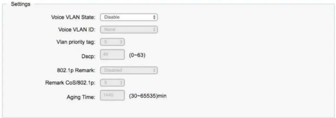
Apply
| Voice VLAN State | Select Enabled or Disabled for Voice VLAN on the Switch. |
| Voice VLAN ID | Sets the Voice VLAN ID for the network. Only one Voice VLAN is supported on the Switch. |
| VLAN priority tag | Set the Voice VLAN COS value for the network |
| DSCP Set the D$CP value for the Voice VLAN | |
| 802.1p Remark | Enable this function to have outgoing voice traffic to be marked with the selected CoS value. |
| Remark CoS/802.1p | Defines a service priority for traffic on the Voice VLAN. The priority of any received VoIP packet is overwritten with the new priority when the Voice VLAN feature is active on a port. (Range: 0 to 7; Default: 6) |
| Aging Time | The aging time is used to remove a port from voice VLAN if the port is an automatic VLAN member. When the last voice device stops sending traffic |
| and the MAC address of this voice device is aged out, the voice VLAN aging timer will be started. The port will be removed from the voice VLAN after expiration of the voice VLAN aging timer. If the voice traffic resumes during the aging time, the aging timer will be reset and stop. The range for aging time is from 1 to 65535 minutes. The default is 1440 minutes. | |
Click Apply to update the system settings.
OUI Settings
The Switches determines whether a received packet is a voice packet by checking its source MAC address. VoIP traffic has a pre-configured Organizationally Unique Identifiers (OUI) prefix in the source MAC address. You can manually add specific manufacturer's MAC addresses and description to the OUI table. All traffic received on the Voice VLAN ports from the specific IP phone with a listed OUI is forwarded on the voice VLAN.
| OUI Settings | |||
| Index | OUI Address | Description | + Add |
| 1 | 00:E0:BB | 3COM | |
| 2 | 00:03:6B | Cisco | |
| 3 | 00:E0:75 | Veritel | |
| 4 | 00:D0:1E | Pingtel | |
| 5 | 00:01:E3 | Siemens | |
| 6 | 00:60:B9 | NEC/Philips | |
| 7 | 00:0F:E2 | H3C | |
| 8 | 00:09:6E | Avaya | |
| Index | Displays the VoIP sequence ID. |
| OUI Address | This is the globally unique ID assigned to a vendor by the IEEE to identify VoIP equipment. |
| Description | Displays the ID of the VoIP equipment vendor. |
To configure the OUI settings, click the Edit button to re-configure the specific entry. Click the Delete button to remove the specific entry and click the Add button to create a new OUI entry. Click the Apply button √ to accept the changes or the Cancel button ✗ to discard them.
Port Settings
Enhance your VoIP service further by configuring ports to carry IP voice traffic from IP phones on a specific VLAN. Voice VLAN provides QoS to VoIP, ensuring that the quality of voice does not deteriorate if the IP traffic is received unevenly.
| Port Settings | ||||
| Port | State | CoS Mode | Operate Status | |
| □ | Disabled | Src | ||
| □ | 1 | Disabled | Src | -- |
| □ | 2 | Disabled | Src | -- |
| □ | 3 | Disabled | Src | -- |
| □ | 4 | Disabled | Src | -- |
| □ | 5 | Disabled | Src | -- |
| □ | 6 | Disabled | Src | -- |
| □ | 7 | Disabled | Src | -- |
| □ | 8 | Disabled | Src | -- |
| □ | 9 | Disabled | Src | -- |
| □ | 10 | Disabled | Src | -- |
| □ | 11 | Disabled | Src | -- |
| □ | 12 | Disabled | Src | -- |
| □ | trunk1 | Disabled | Src | -- |
| □ | trunk2 | Disabled | Src | -- |
| □ | trunk3 | Disabled | Src | -- |
| □ | trunk4 | Disabled | Src | -- |
| Port | Displays the port to which the Voice VLAN settings are applied. |
| State | Select Enabled to enhance VoIP quality on the selected port. The default is Disabled. |
| CoS Mode | Select Src or All from the list. Src: Src QoS attributes are applied to packets with OUIs in the source MAC address.All:All QoS attributes are applied to packets that are classified to the Voice VLAN. |
| Operate Status | Displays the operating status for the Voice VLAN on the selected port. |
Click Apply to update the system settings.
Management
System Information
The System Information screen contains general device information including the system name, system location, and system contact for the Switch.
System Information
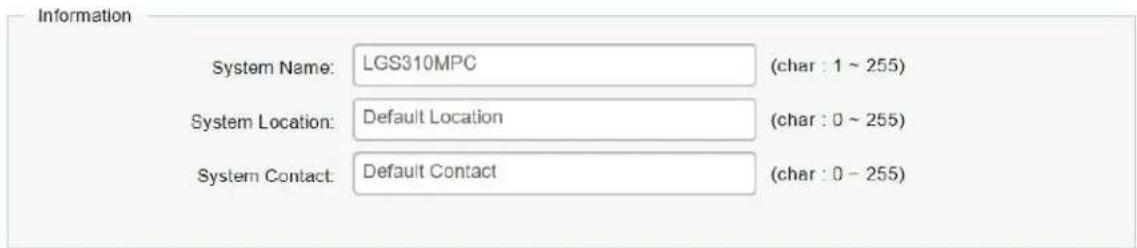
Apply
| System Name | Enter the name you wish to use to identify the Switch. You can use up to 255 alphanumeric characters. |
| System Location | Enter the location of the Switch. You can use up to 255 alphanumeric characters. The factory default is: Default Location. |
| System Contact | Enter the contact person for the Switch. You can use up to 255 alphanumeric characters. The factory default is: Default Location. |
Click Apply to update the system settings.
User Management
Use the User Management page to control management access to the Switch based on manually configured user names and passwords. A User account can only view settings without the right to configure the Switch, and an Admin account can configure all the functions of the Switch. Click the Add button to add an account or the Edit button to edit an existing account.
User Management
| User Name | Password | Password Retype | Privilege Type |  |
| admin | Admin | [S7CH] |
| User Name | Enter a username. You can use up to 18 alphanumeric characters. |
| Password | Enter a new password for accessing the Switch. |
| Password Retype | Repeat the new password used to access the Switch. |
| Privilege Type | Select Admin or User from the list to regulate access rights. |
Important: Note that Admin users have full access rights to the Switch when determining the authority of the user account.
Click the Apply button √ to accept the changes or the Cancel button ✗ to discard them.
Dual Image
The Switch maintains two versions of the Switch image in its permanent storage. One image is the active image, and the second image is the backup image. The Dual Image screen enables the user to select which partition will be set as active after the next reset. The Switch boots and runs from the active image. If the active image is corrupt, the system automatically boots from the non-active image.
Dual Image
| Active | Flash Partition | Status | Image Name | Image Size(Byte) | Created Time |
| ○ | Partition 0 | Backup | IMG-1.05.16-c1.5.3 | 8273849 | 2015-07-07 21:50:12 |
| ● | Partition 1 | Active | IMG-1.05.26-c1.6.24 | 7320132 | 2015-11-13 13:38:03 |
Apply
| Active | Selects the partition you wish to be active. |
| Flash Partition | Displays the number of the partition. |
| Status | Displays the partition which is currently active on the Switch. |
| Image Name | Displays the name/version number of the image |
| Image Size | Displays the size of the image file. |
| Created Time | Displays the time the image was created. |
Click Apply to update the system settings.
ACL
An Access Control List (ACL) allows you to define classification rules or establish criteria to provide security to your network by blocking unauthorized users and allowing authorized users to access specific areas or resources. ACLs can provide basic security for access to the network by controlling whether packets are forwarded or blocked at the Switch ports. Access Control Lists (ACLs) are filters that allow you to classify data packets according to a particular content in the packet header, such as the source address, destination address, source port number, destination port number, and more. Packet classifiers identify flows for more efficient processing. Each filter defines the conditions that must match for inclusion in the filter. ACLs (Access Control Lists) provide packet filtering for IP frames (based on the protocol, TCP/UDP port number or frame type) or layer 2 frames (based on any destination MAC address for unicast, broadcast, or multicast, or based on VLAN ID or VLAN tag priority). ACLs can be used to improve performance by blocking unnecessary network traffic or to implement security controls by restricting access to specific network resources or protocols. Policies can be used to differentiate service for client ports, server ports, network ports, or guest ports. They can also be used to strictly control network traffic by only allowing incoming frames that match the source MAC and source IP address on a specific port. ACLs are composed of Access Control Entries (ACEs), which are rules that determine traffic classifications. Each ACE is a considered as a single rule, and up to 256 rules may be defined on each ACL, with up to 3000 rules globally. ACLs are used to provide traffic flow control, restrict contents of routing updates, and determine which types of traffic are forwarded or blocked. This criterion can be specified on a basis of the MAC address or IP address.
MAC ACL
This page displays the currently defined MAC-based ACLs profiles. To add a new ACL, click Add and enter the name of the new ACL.
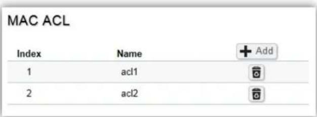
| Index Profile identifier. | |
| Name | Enter the MAC based ACL name. You can use up to 32 alphanumeric characters. |
Click the Apply button √ to accept the changes or the Cancel button ✗ to discard them.
MAC ACE
Use this page to view and add rules to MAC-based ACLs.
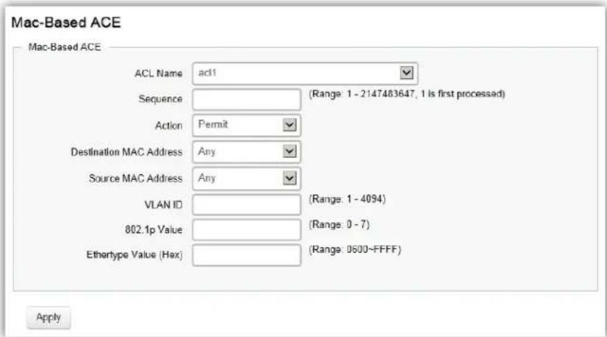
| ACL Name | Select the ACL from the list. |
| Sequence | Enter the sequence number which signifies the order of the specified ACL relative to other ACLs assigned to the selected interface. The valid range is from 1 to 2147483647, 1 being processed first. |
| Action | Select what action taken if a packet matches the criteria. Permit: Forward packets that meet the ACL criteria. Deny: Drops packets that meet the ACL criteria. |
| Destination MAC Value | Enter the destination MAC address. |
| Destination MAC Wildcard Mask | Enter a MAC address mask for the destination MAC address. A mask of 00:00:00:00:00:00 means the bits must be matched exactly; ff:ff:ff:ff:ff:ff means the bits are irrelevant. Any combination of 0s and ffs can be used. |
| Source MAC Value | Enter the source MAC address. |
| Source MAC Wildcard Mask | Enter a MAC address mask for the source MAC address. A mask of 00:00:00:00:00:00 means the bits must be matched exactly; ff:ff:ff:ff:ff:ff means the bits are irrelevant. Any combination of 0s and ffs can be used. |
| VLAN ID | Enter the VLAN ID to which the MAC address is attached in MAC ACE. |
| The range is from 1 to 4094. | |
| 802.1p Value | Enter the 802.1p value. The range is from 0 to 7. |
| Ethertype Value | Selecting this option instructs the Switch to examine the Ethernet type value in each frame's header. This option can only be used to filter Ethernet II formatted packets. A detailed listing of Ethernet protocol types can be found in RFC 1060. A few of the more common types include 0800 (IP), 0806 (ARP), and 8137 (IPX). |
Click Apply to update the system settings.
IPv4 ACL
This page displays the currently defined IPv4-based ACLs profiles. To add a new ACL, click Add and enter the name of the new ACL.
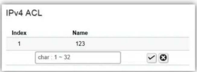
| Index | Displays the current number of ACLs. |
| Name | Enter the IP based ACL name. You can use up to 32 alphanumeric characters. |
Click the Apply button √ to accept the changes or the Cancel button ✗ to discard them.
IPv4 ACE
Use this page to view and add rules to IPv4-based ACLs.
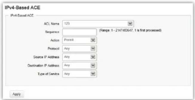
| ACL Name | Select the ACL from the list for which a rule is being created. |
| Sequence | Enter the sequence number which signifies the order of the specified ACL relative to other ACLs assigned to the selected interface. The valid range is from 1 to 2147483647, 1 being processed first. |
| Action | Select what action to take if a packet matches the criteria.Permit: Forwards packets that meet the ACL criteria.Deny: Drops packets that meet the ACL criteria. |
| Protocol | Select Any, Protocol ID, or Select from a List in the drop-down menu.Any: Check Any to use any protocol.Protocol ID: Enter the protocol in the ACE to which the packet is matched.Select from List: Selects the protocol from the list in the provided field.ICMP: Internet Control Message Protocol (ICMP). The ICMP enables the gateway or destination host to communicate with the source host.IPinIP: IP in IP encapsulates IP packets to create tunnels between two routers. This ensures that IP in IP tunnel appears as a single interface, rather than several separate interfaces.TCP: Transmission Control Protocol (TCP). Enables two hosts to communicate and exchange data streams. TCP guarantees packet delivery, and guarantees that packets are transmitted and received in the order they are sent. EGP Exterior Gateway Protocol (EGP). Permits exchanging routing information between two neighboring gateway hosts in an autonomous systems network.IGP: Interior Gateway Protocol (IGP). Enables a routing information exchange between gateways within an autonomous network.UDP: User Datagram Protocol (UDP). UDP is a communication protocol that transmits packets but does not guarantee their delivery.HMP: The Host Mapping Protocol (HMP) collects network information from various networks hosts. HMP monitors hosts spread over the Internet as well as hosts in a single network.RDP: Reliable Data Protocol (RDP). Provides a reliable data transport service for packet-based applications.IPv6: Matches the packet to the IPV6 protocol.IPv6: Rout: Routing Header for IPv6.IPv6: Frag: Fragment Header for IPv6.RVSP: Matches the packet to the ReSerVation Protocol (RSVP).IPv6: ICMP: The Internet Control Message Protocol (ICMP) allows the gateway or destination host to communicate with the source host.OSPF: The Open Shortest Path First (OSPF) protocol is a link-state hierarchical interior gateway protocol (IGP) for network routing Layer Two (2) Tunneling Protocols. It is an extension to the PPP protocol that enables ISPs to operate Virtual Private Networks (VPNs).PIM: Matches the packet to Protocol Independent Multicast (PIM).L2TP: Matches the packet to Internet Protocol (L2IP). |
| Source IP Address Value | Enter the source IP address. |
| Source IP Mask | Enter the mask of the new source IP address. |
| Destination IP Address Value | Enter the destination IP address. |
| Destination IP Mask | Enter the mask of the new source IP address. |
| Type of Service | Select Any or DSCP to match from drop-down list. When DSCP to match is selected, enter the DSCP. The range is from 0 to 63. |
| ICMP Type | Select Any, Protocol ID, or Select from List from drop-down menu.Protocol ID: Enter the protocol in the ACE to which the packet is matched. The range is from 0 to 255.Select from List: Select the ICMP from the list in the provided field. |
| ICMP Code | Select Any or User Defined from drop-down menu. When User Defined is selected, enter the ICMP code value. The range is from 0 to 255. |
Click Apply to update the system settings.
IPv6 ACL
This page displays the currently defined IPv6-based ACLs profiles. To add a new ACL, click Add and enter the name of the new ACL.
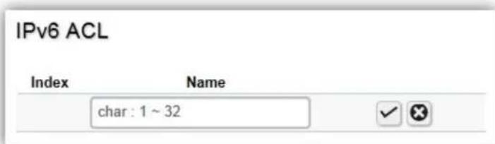
| Index | Displays the current number of ACLs. |
| Name | Enter the IPv6 based ACL name. You can use up to 32 alphanumeric characters. |
Click the Apply button √ to accept the changes or the Cancel button ✗ to discard them.
IPv6 ACE
Allows IPv6 Based Access Control Entry (ACE) to be defined within a configured ACL.
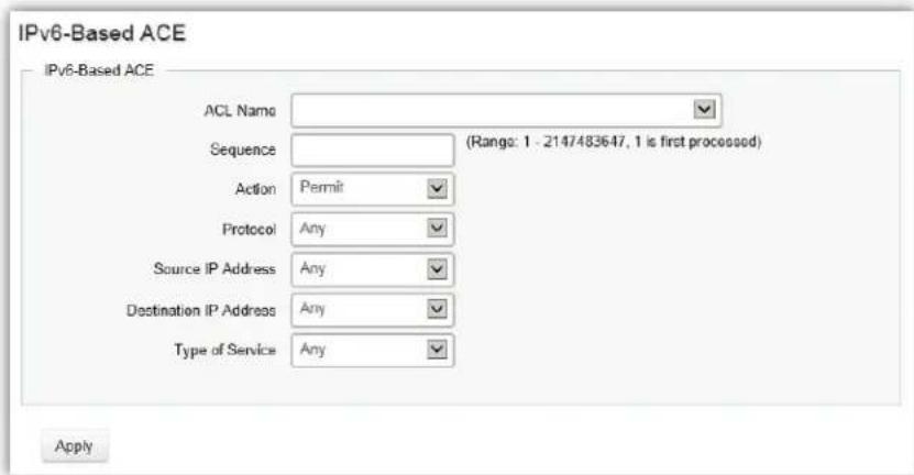
| ACL Name | Select the ACL from the list. |
| Sequence | Enter the sequence number which signifies the order of the specified ACL relative to other ACLs assigned to the selected interface. The valid range is from 1 to 2147483647, 1 being processed first. |
| Action | Select what action taken if a packet matches the criteria. Permit: Forward packets that meet the ACL criteria. Deny: Drops packets that meet the ACL criteria. |
| Protocol | Select the Any, Protocol ID, or Select from List from drop-down menu. Protocol ID: Enter the protocol in the ACE to which the packet is matched. Select from List: Select the protocol from the list in the provided field. |
| Source IP Address Value | Enter the source IP address. |
| Source IP Prefix Length | Enter the prefix length of the new source IP address. The range is from 0 to 128. |
| Destination IP Address Value | Enter the destination IP address. |
| Destination IP Prefix Length | Enter the prefix length of the new source IP address. The range is from 0 to 128. |
| Source Port | Select Single or Range from the list. Enter the source port that is matched to packets. The range is from 0 to 65535. |
| Destination Port | Select Single or Range from the list. Enter the destination port that is matched to packets. The range is from 0 to 65535. |
| TCP Flags | Select whether to handle each six TCP control flags; URG (Urgent), ACK (Acknowledgment), PSH (Push), RST (Reset), SYN (Synchronize), and FIN (Fin) from drop-down menu. Don't Care: The ACE do not treat the TCP control flag. Set: The packet with the TCP control flag being set matches the criteria. Unset: The packet with the TCP control flag being unset matches the criteria. |
| Type of Service Select | Any or DSCP to match from drop down list. When DSCP to match is selected, enter the DSCP. The range is from 0 to 63. |
Click Apply to update the system settings.
ACL Binding
When an ACL is bound to an interface, all the rules that have been defined for the ACL are applied to that interface. Whenever an ACL is assigned on a port or LAG, flows from that ingress or egress interface that do not match the ACL, are matched to the default rule of dropping unmatched packets. To bind an ACL to an interface, simply select an interface and select the ACL(s) you wish to bind.
ACL Binding
| Port | MAC ACL | IPv4 ACL | IPv6 ACL | |
| □ | (none) ▼ | (none) ▼ | (none) ▼ | |
| □ | 1 | |||
| □ | 2 | |||
| □ | 3 | |||
| □ | 4 | |||
| □ | 5 |
| Port | Select the port for which the ACLs are bound to. |
| MAC ACL | Select the MAC ACL rule to apply to the port. |
| IPv4 ACL | Select the IPv4 ACL rule to apply to the port. |
| IPv6 ACL | Select the IPv6 ACL rule to apply to the port. |
Click Apply to update the system settings.
QoS
Quality of Service (QoS) provides the ability to implement priority queuing within a network. QoS is a means of providing consistent and predictable data delivery to the Switch by distinguishing between packets that have stricter timing requirements from those that are more tolerant of delays. QoS enables traffic to be prioritized while avoiding excessive broadcast and multicast traffic. Traffic such as Voice and Video streaming which require minimal delays can be assigned to a high priority queue, while other traffic can be assigned to a lower priority queue, resulting in uninterrupted actions. Without QoS, all traffic data is as likely to be dropped when the network is congested. This can result in reductions in network performance and hinder the network in time-critical situations.
In a Switch, multiple queues per port are often provided to give preference to certain packets over others based on user-defined criteria. When a packet is queued for transmission within a port, the rate at which it is processed depends on how the queue is configured and the amount of traffic present within other queues on the port. If a delay is necessary, packets are held in the queue until they are authorized for transmission.
Global Settings
There are two options for applying QoS information onto packets: the 802.1p Class of Service (CoS) priority field within the VLAN tag of tagged Ethernet frames, and Differentiated Services (DiffServ) Code Point (DSCP). Each port on the Switch can be configured to trust one of the packet fields (802.1p, DSCP or DSCP+802.1p). Packets that enter the Switch's port may carry no QoS information as well. If so, the Switch places such information into the packets before transmitting them to the next node. Thus, QoS information is preserved between nodes within the network and the nodes know which label to give each packet. A trusted field must exist in the packet for the mapping table to be of any use. When a port is configured as untrusted, it does not trust any incoming packet priority designations and uses the port default priority value instead to process the packet.
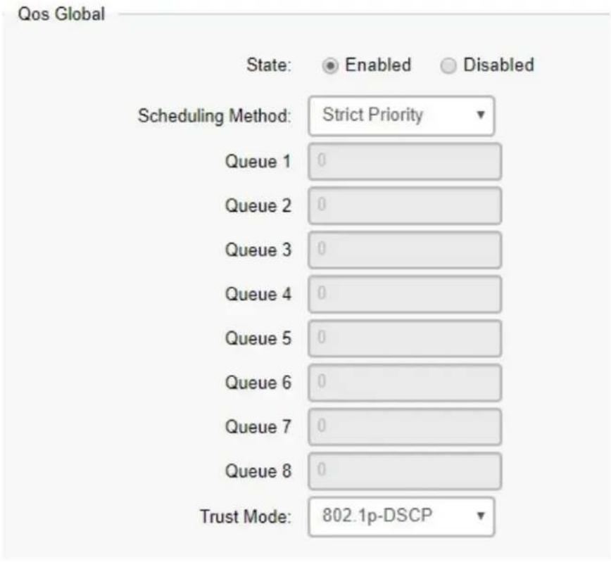
| State | Select whether QoS is enabled or disabled on the switch. |
| Scheduling Method | Selects the Strict Priority or WRR to specify the traffic scheduling method.Strict Priority: Specifies traffic scheduling based strictly on the queue priority.WRR: Use the Weighted Round-Robin (WRR) algorithm to handle packets in priority classes of service. It assigns WRR weights to queues. |
| Queue 1-8 | Select the queue proportion when using the WRR mode. |
| Trust Mode | Select which packet fields to use for classifying packets entering the Switch.802.1p-DSCP: Classify traffic based on 802.1p and DSCP depend on if packet have tar or not.DSCP: Classify traffic based on the DSCP (Differentiated Services Code Point) tag value.802.1p: Classify traffic based on the 802.1p. The eight priority tags that are specified in IEEE 802.1p are from 1 to 8. |
Click Apply to update the system settings.
CoS Mapping
Use the Class of Service (CoS) Mapping feature to specify which internal traffic class to map to the corresponding CoS value. CoS allows you to specify which data packets have greater precedence when traffic is buffered due to congestion.
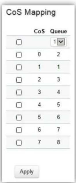
| CoS | Displays the CoS priority tag values, where 0 is the lowest and 7 is the highest. |
| Queue | Check the CoS priority tag box and select the Queue values for each CoS value in the provided fields. Eight traffic priority queues are supported and the field values are from 1 to 8, where one is the lowest priority and eight is the highest priority. |
Click Apply to update the system settings.
DSCP Mapping
Use Differentiated Services Code Point (DSCP) Mapping feature to specify which internal traffic class to map to the corresponding DSCP values. DSCP Mapping increases the number of definable priority levels by reallocating bits of an IP packet for prioritization purposes.
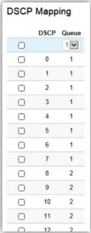
| DSCP | Displays the packet's DSCP values, where 0 is the lowest and 10 is the highest. |
| Queue | Check the CoS priority tag box and select the Queue values for each DSCP in the provided fields. Eight traffic priority queues are supported and the field values are from 1 to 8, where one is the lowest priority and eight is the highest priority. |
Click Apply to update the system settings.
Port Settings
From here, you can configure the QoS port settings for the Switch. Select a port you wish to set and choose a CoS value from the dropdown box. Next, select to enable or disable the Trust setting to let any CoS packet be marked at ingress.
Port Settings
| Port | CoS Value | Trust | |
| 0▼ | Enabled▼ | ||
| 1 | 0 | Disabled | |
| 2 | 0 | Disabled | |
| 3 | 0 | Disabled | |
| 4 | 0 | Disabled | |
| 5 | 0 | Disabled | |
| 6 | 0 | Disabled | |
| 7 | 0 | Disabled | |
| 8 | 0 | Disabled | |
| 9 | 0 | Disabled | |
| 10 | 0 | Disabled | |
| 11 | 0 | Disabled | |
| 12 | 0 | Disabled | |
| 13 | 0 | Disabled | |
| 14 | 0 | Disabled |
| Port | Displays the ports for which the CoS parameters are defined. |
| CoS Value | Select the CoS priority tag values, where 0 is the lowest and 7 is the highest. |
| Trust | Select Enabled to trust any CoS packet marking at ingress. Select Disabled to not trust any CoS packet marking at ingress. |
Click Apply to update the system settings.
Advanced Settings
Set the new 802.1p or DSCP value on specific packets.
Class Mapping
Class Policy
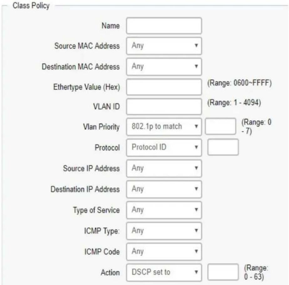
| Name | Set the class policy name. |
| Source Mac Address | Define the source MAC address. |
| Destination Mac Address | Define the destination MAC address. |
| Ethertype Value | Define the specific ehtertype. |
| VLAN ID | Define the specific VLAN ID |
| VLAN Priority | Define the VLAN or 802.1p value. |
| Protocol | Define the specific protocol. (select from list or protocol ID) |
| Source IP Address | Define the source IP address. |
| Destination IP Address | Define the destination IP address. |
| Type of Service | Define the specific ToS. |
| Action | Set the packet 802.1p value or DSCP to specific vlan when packet meet the rule. |
Policy Mapping
Display the information with class mapping.
| Policy Name | Display the policy name when any packet meet in the class mapping. |
| Binding Ports | Display the binding ports when any packet meet in the class mapping. |
Bandwidth Control
The Bandwidth Control feature allows users to define the bandwidth settings for a specified port's Ingress Rate Limit and Egress Rate.
| Bandwidth Control | |||||
| Port | Ingress | Ingress Rate (kbps) | Egress | Egress Rate (kbps) | |
| □ | Disabled | 1000000 | Disabled | 1000000 | |
| □ | 1 | Disabled | Off | Disabled | Off |
| □ | 2 | Disabled | Off | Disabled | Off |
| □ | 3 | Disabled | Off | Disabled | Off |
| □ | 4 | Disabled | Off | Disabled | Off |
| □ | 5 | Disabled | Off | Disabled | Off |
| □ | 6 | Disabled | Off | Disabled | Off |
| □ | 7 | Disabled | Off | Disabled | Off |
| □ | 8 | Disabled | Off | Disabled | Off |
| □ | 9 | Disabled | Off | Disabled | Off |
| □ | 10 | Disabled | Off | Disabled | Off |
| □ | 11 | Disabled | Off | Disabled | Off |
| □ | 12 | Disabled | Off | Disabled | Off |
| Port | Displays the ports for which the bandwidth settings are displayed. |
| Ingres | Select enable or disable ingress on the interface. |
| Ingress Rate | Enter the ingress rate in kilobits per second. The gigabit Ethernet ports have a maximum speed of 1000000 kilobits per second. |
| Egress | Select from the drop-down box to Enable or Disable egress on the interface. |
| Egress Rate | Enter the egress rate in kilobits per second. The gigabit Ethernet ports have a maximum speed of 1000000 kilobits per second. |
Click Apply to update the system settings.
Storm Control
Storm Control limits the amount of Broadcast, Unknown Multicast, and Unknown Unicast frames accepted and forwarded by the Switch. Storm Control can be enabled per port by defining the packet type and the rate that the packets are transmitted at. The Switch measures the incoming Broadcast, Unknown Multicast, and Unknown Unicast frames rates separately on each port, and discards the frames when the rate exceeds a user-defined rate.
Storm Control
| Port | Broadcast (kbps) | Unknown Multicast (kbps) | Unknown Unicast (kbps) | |
| 16~1000000.Enter 16°N | 16~1000000.Enter 16°N | 16~1000000.Enter 16°N | ||
| 1 | Off | Off | Off | |
| 2 | Off | Off | Off | |
| 3 | Off | Off | Off | |
| 4 | Off | Off | Off | |
| 5 | Off | Off | Off | |
| 6 | Off | Off | Off | |
| 7 | Off | Off | Off | |
| 8 | Off | Off | Off | |
| 9 | Off | Off | Off | |
| 10 | Off | Off | Off | |
| 11 | Off | Off | Off | |
| 12 | Off | Off | Off |
Apply
| Port | Displays the ports for which the Storm Control information is displayed. |
| Status | Select whether Storm Control is Enabled or Disabled ingress on the interface. |
| Broadcast | Enter the broadcast rate in kilobits per second. The Gigabit Ethernet ports have a maximum speed of 1000000 kilobits per second. If the rate of broadcast traffic ingress on the interface increases beyond the configured threshold, the traffic is dropped. |
| Unknown Multicast | Enter the Unknown Multicast rate in kilobits per second. The gigabit Ethernet ports have a maximum speed of 1000000 kilobits per second. If the rate of broadcast traffic ingress on the interface increases beyond the configured threshold, the traffic is dropped. |
| Unknown Unicast | Enter the Unknown Unicast rate in kilobits per second. The gigabit Ethernet ports have a maximum speed of 1000000 kilobits per second. If the rate of broadcast traffic ingress on the interface increases beyond the configured threshold, the traffic is dropped. |
Click Apply to update the system settings.
Security
802.1x
The IEEE 802.1X standard authentication uses the RADIUS (Remote Authentication Dial In User Service) protocol to validate users and provide a security standard for network access control. The user that wishes to be authenticated is called a supplicant. The actual server doing the authentication, typically a RADIUS server, is called the authentication server. The mediating device, such as a Switch, is called the authenticator. Clients connected to a port on the Switch must be authenticated by the Authentication server (RADIUS) before accessing any services offered by the Switch on the LAN. Use a RADIUS server to authenticate users trying to access a network by relaying Extensible Authentication Protocol over LAN (EAPOL) packets between the client and server. This establishes the requirements needed for a protocol between the authenticator (the system that passes an authentication request to the authentication server) and the supplicant (the system that requests authentication), as well as between the authenticator and the authentication server.
Global Settings
When a supplicant is connected to a Switch port, the port issues an 802.1X authentication request to the attached the 802.1X supplicant. The supplicant replies with the given username and password in an authentication request, then passed to a configured RADIUS server. The authentication server's user database supports Extended Authentication Protocol (EAP), which allows particular guest VLAN memberships to be defined based on each individual user. Before successful authorization, the port connected to the authenticated supplicant becomes a member of the specified guest VLAN. When the supplicant is successfully authenticated, traffic will be automatically assigned to the VLAN user configured in 802.1Q VLAN. The EAP authentication methods supported by the Switch are: EAP-MD5, EAPTLS, EAP-TTLS, and EAP-PEAP.
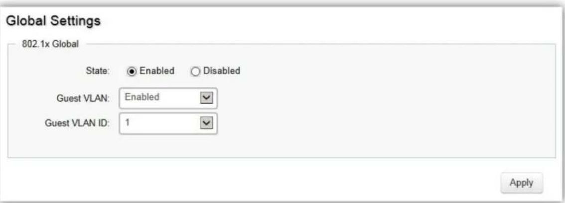
| State | Select authentication is Enabled or Disabled on the Switch. |
| Guest VLAN | Select Guest VLAN is Enabled or Disabled on the Switch. The default is Disabled. |
| Guest VLAN ID | Select the guest VLAN ID from the list of currently defined VLANs. |
Click Apply to update the system settings.
Port Settings
The IEEE 802.1X port-based authentication provides a security standard for network access control with RADIUS servers and holds a network port block, until authentication is completed. With 802.1X port-based authentication, the supplicant provides the required credentials, such as user name, password, or digital certificate to the authenticator, and the authenticator forwards the credentials to the authentication server for verification. If the authentication server determines the credentials are valid, the supplicant is allowed to access resources located on the protected side of the network.
From here, you can configure the port settings as they relate to 802.1X. First, select the mode you wish to utilize from the drop-down box. Next, choose enable or disable re-authentication setting for the port. Enter the time span that you wish to elapse for the re-authentication Period, Quiet Period, and Supplicant Period. After this, enter the max number of times you wish for the Switch to retransmit the EAP request. Finally, choose you wish to enable or disable the Guest VLAN.
Port Settings
| Port | Mode | Reauthentication | Reauthentication Period | Quiet Period | Supplicant Period | Authorized Status | Guest VLAN | RADIUS VLAN Assign | |
| Auto ‡ | Enabled ‡ | 3600 | 60 | 30 | Disabled ‡ | Disabled ‡ | |||
| 1 | Force_Authorized | Disabled | 3600 | 60 | 30 | AUTH_FORCEAUTH | Disabled | Enabled | |
| 2 | Force_Authorized | Disabled | 3600 | 60 | 30 | AUTH_INITIALIZE | Disabled | Enabled | |
| 3 | Force_Authorized | Disabled | 3600 | 60 | 30 | AUTH_INITIALIZE | Disabled | Enabled | |
| 4 | Force_Authorized | Disabled | 3600 | 60 | 30 | AUTH_INITIALIZE | Disabled | Enabled | |
| 5 | Force_Authorized | Disabled | 3600 | 60 | 30 | AUTH_INITIALIZE | Disabled | Enabled | |
| 6 | Force_Authorized | Disabled | 3600 | 60 | 30 | AUTH_INITIALIZE | Disabled | Enabled | |
| 7 | Force_Authorized | Disabled | 3600 | 60 | 30 | AUTH_INITIALIZE | Disabled | Enabled | |
| 8 | Force_Authorized | Disabled | 3600 | 60 | 30 | AUTH_INITIALIZE | Disabled | Enabled | |
| 9 | Force_Authorized | Disabled | 3600 | 60 | 30 | AUTH_INITIALIZE | Disabled | Enabled | |
| 10 | Force_Authorized | Disabled | 3600 | 60 | 30 | AUTH_INITIALIZE | Disabled | Enabled | |
| 11 | Force_Authorized | Disabled | 3600 | 60 | 30 | AUTH_INITIALIZE | Disabled | Enabled | |
| 12 | Force_Authorized | Disabled | 3600 | 60 | 30 | AUTH_INITIALIZE | Disabled | Enabled | |
| 13 | Force_Authorized | Disabled | 3600 | 60 | 30 | AUTH_INITIALIZE | Disabled | Enabled | |
| 14 | Force_Authorized | Disabled | 3600 | 60 | 30 | AUTH_INITIALIZE | Disabled | Enabled | |
| 15 | Force_Authorized | Disabled | 3600 | 60 | 30 | AUTH_INITIALIZE | Disabled | Enabled | |
| 16 | Force_Authorized | Disabled | 3600 | 60 | 30 | AUTH_INITIALIZE | Disabled | Enabled | |
| 17 | Force_Authorized | Disabled | 3600 | 60 | 30 | AUTH_INITIALIZE | Disabled | Enabled | |
| 18 | Force_Authorized | Disabled | 3600 | 60 | 30 | AUTH_INITIALIZE | Disabled | Enabled | |
| 19 | Force_Authorized | Disabled | 3600 | 60 | 30 | AUTH_INITIALIZE | Disabled | Enabled | |
| 20 | Force_Authorized | Disabled | 3600 | 60 | 30 | AUTH_INITIALIZE | Disabled | Enabled | |
| 21 | Force_Authorized | Disabled | 3600 | 60 | 30 | AUTH_INITIALIZE | Disabled | Enabled | |
| 22 | Force_Authorized | Disabled | 3600 | 60 | 30 | AUTH_INITIALIZE | Disabled | Enabled | |
| 23 | Force_Authorized | Disabled | 3600 | 60 | 30 | AUTH_INITIALIZE | Disabled | Enabled | |
| 24 | Force_Authorized | Disabled | 3600 | 60 | 30 | AUTH_INITIALIZE | Disabled | Enabled | |
| 25 | Force_Authorized | Disabled | 3600 | 60 | 30 | AUTH_INITIALIZE | Disabled | Enabled | |
| 26 | Force_Authorized | Disabled | 3600 | 60 | 30 | AUTH_INITIALIZE | Disabled | Enabled | |
| 27 | Force_Authorized | Disabled | 3600 | 60 | 30 | AUTH_INITIALIZE | Disabled | Enabled | |
| 28 | Force_Authorized | Disabled | 3600 | 60 | 30 | AUTH_INITIALIZE | Disabled | Enabled |
| Port | Displays the ports for which the 802.1X information is displayed. |
| Mode | Select Auto or Force_UnAuthorized or Force_Authorized mode from the list. |
| Re-Authentication | Select port re-authentication is Enabled or Disabled. |
| Re-authentication period | Enter the time span in which the selected port is re-authenticated. The default is 3600 seconds. |
| Quiet Period | Enter the number of the device that remains in the quiet state following a failed authentication exchange. The default is 60 seconds. |
| Supplicant Period | Enter the amount of time that lapses before an EAP request is resent to the supplicant. The default is 30 seconds. |
| Authorized Status | Displays the authorized status of 802.1x information. |
| Guest VLAN | Select guest VLAN is Enabled or Disabled on specific ports. |
| RADIUS VLAN Assign | Enable the feature client will get the VLAN from RADIUS server. |
Click Apply to update the system settings.
Authenticated Host
The Authenticated Host section displays the Authenticated Port, Authenticated Method, and Mac Address.
Authenticated Host
| User Name | Port | Session Time | Authenticate Method | MAC Address | Dynamic VLAN Cause | Dynamic VLAN ID |
| wahaha | 3 | 2400 | Radius | 2C:4D:54:C4:B0:DE | 802.1Q Static VLAN | 0 |
| User Name | Display client's username via 802.1x RADIUS server authentication. |
| Port | Display client's authenticated port number. |
| Session Time | Display client's 802.1x session time. |
| Authenticate Method | Display client's authenticated method. |
| MAC Address | Display client's MAC address. |
| Dynamic VLAN Cause | Display client's VLAN information. |
| Dynamic VLAN ID | Display client's VLAN ID if RADIUS server assign it. |
Statistics
Display 802.1x related packet counters and source MAC of last received 802.1x packet on each port.
Statistics
| Port | TxReqId | TxReq | TxTotal | RxStart | RxLogoff | RxRespld | RxResp | RxInvalid | RxLenErr | RxTotal | RxVersion | LastRxSrcMac | |
| 1 | 0 | 0 | 0 | 0 | 0 | 0 | 0 | 0 | 0 | 0 | 0 | 00:00:00:00:00:00 | |
| 2 | 0 | 0 | 0 | 0 | 0 | 0 | 0 | 0 | 0 | 0 | 0 | 00:00:00:00:00:00 | |
| 3 | 0 | 0 | 0 | 0 | 0 | 0 | 0 | 0 | 0 | 0 | 0 | 00:00:00:00:00:00 | |
| 4 | 0 | 0 | 0 | 0 | 0 | 0 | 0 | 0 | 0 | 0 | 0 | 00:00:00:00:00:00 | |
| 5 | 0 | 0 | 0 | 0 | 0 | 0 | 0 | 0 | 0 | 0 | 0 | 00:00:00:00:00:00 | |
| 6 | 0 | 0 | 0 | 0 | 0 | 0 | 0 | 0 | 0 | 0 | 0 | 00:00:00:00:00:00 | |
| 7 | 0 | 0 | 0 | 0 | 0 | 0 | 0 | 0 | 0 | 0 | 0 | 00:00:00:00:00:00 | |
| 8 | 0 | 0 | 0 | 0 | 0 | 0 | 0 | 0 | 0 | 0 | 0 | 00:00:00:00:00:00 | |
| 9 | 0 | 0 | 0 | 0 | 0 | 0 | 0 | 0 | 0 | 0 | 0 | 00:00:00:00:00:00 | |
| 10 | 0 | 0 | 0 | 0 | 0 | 0 | 0 | 0 | 0 | 0 | 0 | 00:00:00:00:00:00 | |
| 11 | 0 | 0 | 0 | 0 | 0 | 0 | 0 | 0 | 0 | 0 | 0 | 00:00:00:00:00:00 | |
| 12 | 0 | 0 | 0 | 0 | 0 | 0 | 0 | 0 | 0 | 0 | 0 | 00:00:00:00:00:00 |
Clear
Click Clear to clear 802.1x packet counters on specific ports.
RADIUS Server
RADIUS servers are used for centralized administration. Remote Authentication Dial In User Service (RADIUS) is a networking protocol that provides centralized Authentication, Authorization, and Accounting (AAA) management for users that connect and use a network service for greater convenience. RADIUS is a server protocol that runs in the application layer, using UDP as transport. The Network Switch with port-based authentication and all have a RADIUS client component that communicates with the RADIUS server. Clients connected to a port on the Switch must be authenticated by the Authentication server before accessing services offered by the Switch on the LAN. Use a RADIUS server to authenticate users trying to access a network by relaying Extensible Authentication Protocol over LAN (EAPOL) packets between the client and server. The RADIUS server maintains a user database, which contains authentication information. The Switch passes information to the configured RADIUS server, which can authenticate a user name and password before authorizing use of the network.
Radius Server
| Index | Server IP | Authorized Port | Key String | Timeout Reply | Retry |
| x.x.x.x | 1812 | char . 0 ~ 63 | 3 | 3 |
| Index | Displays the index for which RADIUS server is displayed. |
| Server IP | Enter the RADIUS server IP address. |
| Authorized Port | Enter the authorized port number. The default port is 1812. |
| Accounting Port | Enter the name you wish to use to identify this Switch. |
| Key String | Enter the key string used for encrypting all RADIUS communication between the device and the RADIUS server. |
| Timeout Reply | Enter the time device waits for an answer from the RADIUS server before switching to the next server. The default value is 3. |
| Retry | Enter the number of transmitted requests sent to the RADIUS server before a failure occurs. The default is 3. |
Click the Apply button √ to accept the changes or the Cancel button ✗ to discard them.
Access
The Linksys switch provides a built-in browser interface that you can configure and manage the Switch via Hypertext Transfer Protocol (HTTP) and Hypertext Transfer Protocol Secure (HTTPS) requests selectively to help prevent security breaches on the network. You can manage your HTTP and HTTPS settings for the Switch further by configuring session timeouts for HTTP and HTTPS requests. Select enable or disable the HTTP service and enter the HTTP Timeout session. Next, select enable or disable the HTTPS service and enter the HTTPS timeout session for the Switch.
The Telnet protocol is a standard Internet protocol which enables terminals and applications to interface over the Internet with remote hosts by providing Command Line Interface (CLI) communication using a virtual terminal connection. This protocol provides the basic rules for making it possible to link a client to a command interpreter. The Telnet service for the Switch is enabled by default. Please note that for secure communication, it is better to use SSH over Telnet.
Secure Shell (SSH) is a cryptographic network protocol for secure data communication network services. SSH is a way of accessing the command line interface on the network Switch. The traffic is encrypted, so it is difficult to eavesdrop on as it creates a secure connection within an insecure network such as the Internet. Even if an attacker was able to view the traffic, the data would be incomprehensible without the correct encryption key to decode it.
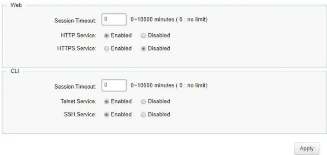
| HTTP SessionTimeout | Enter the amount of time that elapses before HTTP is timed out. The default is 5 minutes. The range is from 0 to 10000 minutes. |
| HTTP Service | Select HTTP service for the Switch is Enabled or Disabled. This is enabled by default. |
| HTTPS Service | Select the HTTP service is Enabled or Disabled. This is disabled by default. |
| CLI Session Timeout | Enter the amount of time that elapses before telnet/SSH is timed out. The default is 5 minutes. The range is from 0 to 10000 minutes. |
| Telnet Service | Select Telnet service for the Switch is Enabled or Disabled. This is enabled by default. |
| SSH Service | Select the SSH service is Enabled or Disabled. This is disabled by default. |
Click Apply to update the system settings.
Port Security
Network security can be increased by limiting access on a specific port to users with specific MAC addresses. Port Security prevents unauthorized device to the Switch prior to stopping auto-learning processing.
| Port Security | |||
| Port | State | Max MAC Address | |
| □ | Disabled | 256 | |
| □ | 1 | Disabled | 256 |
| □ | 2 | Disabled | 256 |
| □ | 3 | Disabled | 256 |
| □ | 4 | Disabled | 256 |
| □ | 5 | Disabled | 256 |
| □ | 6 | Disabled | 256 |
| □ | 7 | Disabled | 256 |
| □ | 8 | Disabled | 256 |
| □ | 9 | Disabled | 256 |
| □ | 10 | Disabled | 256 |
| □ | 11 | Disabled | 256 |
| □ | 12 | Disabled | 256 |
| Max MAC Address | Enter the maximum number of MAC addresses that can be learned on the port. The range is from 1 to 256. |
| Port | Displays the port for which the port security is defined. |
| State | Select Enabled or Disabled for the port security feature for the selected port. |
Click Apply to update the system settings.
Port Isolation
Port Isolation feature provides L2 isolation between ports within the same broadcast domain. When enabled, Isolated ports can forward traffic to Not Isolated ports, but not to other Isolated ports. Not Isolated ports can send traffic to any port; whether Isolated or Not Isolated. The default setting is Not Isolated.
| Port Isolation | ||
| Port | Status | |
| □ | Not Isolated | |
| □ | 1 | Not Isolated |
| □ | 2 | Not Isolated |
| □ | 3 | Not Isolated |
| □ | 4 | Not Isolated |
| □ | 5 | Not Isolated |
| □ | 6 | Not Isolated |
| □ | 7 | Not Isolated |
| □ | 8 | Not Isolated |
| □ | 9 | Not Isolated |
| □ | 10 | Not Isolated |
Click Apply to update the system settings.
DoS
DoS (Denial of Service) is used for classifying and blocking specific types of DoS attacks. From here, you can configure the Switch to monitor and block different types of attacks.
Global Settings
On this page, the user can enable or disable the prevention of DoS attacks globally. When enabled, the switch will drop the packets matching the types of DoS attack detected.
Global Settings

Click Apply to update the system settings.
Monitoring
Port Statistics
The Port Statistics page displays a summary of all port traffic statistics.
Port Statistics
| Port | RXOctets | RXUcast | RXNUcast | RXDiscard | RXMcast | RXBcast | RXError | HCInCount | TXOctets | TXUcast | TXNUcast | TXDiscard | TXMcast | TXBcast | TXError | HCOutCount | |
| 1 | 0 | 0 | 0 | 0 | 0 | 0 | 0 | 0 | 0 | 0 | 0 | 0 | 0 | 0 | 0 | 0 | |
| 2 | 19347983 | 484 | 86893 | 0 | 53906 | 32987 | 0 | 19347983 | 168901 | 5 | 1153 | 0 | 1035 | 118 | 0 | 169901 | |
| 3 | 221780 | 1021 | 441 | 0 | 367 | 74 | 0 | 221780 | 710637 | 786 | 4841 | 0 | 4832 | 9 | 0 | 710637 | |
| 4 | 0 | 0 | 0 | 0 | 0 | 0 | 0 | 0 | 0 | 0 | 0 | 0 | 0 | 0 | 0 | 0 | |
| 5 | 0 | 0 | 0 | 0 | 0 | 0 | 0 | 0 | 0 | 0 | 0 | 0 | 0 | 0 | 0 | 0 | |
| 6 | 0 | 0 | 0 | 0 | 0 | 0 | 0 | 0 | 0 | 0 | 0 | 0 | 0 | 0 | 0 | 0 | |
| 7 | 0 | 0 | 0 | 0 | 0 | 0 | 0 | 0 | 0 | 0 | 0 | 0 | 0 | 0 | 0 | 0 | |
| 8 | 0 | 0 | 0 | 0 | 0 | 0 | 0 | 0 | 0 | 0 | 0 | 0 | 0 | 0 | 0 | 0 | |
| 9 | 0 | 0 | 0 | 0 | 0 | 0 | 0 | 0 | 0 | 0 | 0 | 0 | 0 | 0 | 0 | 0 | |
| 10 | 0 | 0 | 0 | 0 | 0 | 0 | 0 | 0 | 0 | 0 | 0 | 0 | 0 | 0 | 0 | 0 | |
| 11 | 0 | 0 | 0 | 0 | 0 | 0 | 0 | 0 | 0 | 0 | 0 | 0 | 0 | 0 | 0 | 0 | |
| 12 | 0 | 0 | 0 | 0 | 0 | 0 | 0 | 0 | 0 | 0 | 0 | 0 | 0 | 0 | 0 | 0 | |
| trunk1 | 0 | 0 | 0 | 0 | 0 | 0 | 0 | 0 | 0 | 0 | 0 | 0 | 0 | 0 | 0 | 0 | |
| trunk2 | 0 | 0 | 0 | 0 | 0 | 0 | 0 | 0 | 0 | 0 | 0 | 0 | 0 | 0 | 0 | 0 | |
| trunk3 | 0 | 0 | 0 | 0 | 0 | 0 | 0 | 0 | 0 | 0 | 0 | 0 | 0 | 0 | 0 | 0 | |
| trunk4 | 0 | 0 | 0 | 0 | 0 | 0 | 0 | 0 | 0 | 0 | 0 | 0 | 0 | 0 | 0 | 0 | |
| trunk5 | 0 | 0 | 0 | 0 | 0 | 0 | 0 | 0 | 0 | 0 | 0 | 0 | 0 | 0 | 0 | 0 | |
| trunk6 | 0 | 0 | 0 | 0 | 0 | 0 | 0 | 0 | 0 | 0 | 0 | 0 | 0 | 0 | 0 | 0 | |
| trunk7 | 0 | 0 | 0 | 0 | 0 | 0 | 0 | 0 | 0 | 0 | 0 | 0 | 0 | 0 | 0 | 0 | |
| trunk8 | 0 | 0 | 0 | 0 | 0 | 0 | 0 | 0 | 0 | 0 | 0 | 0 | 0 | 0 | 0 | 0 | |
Clear
| Port | Displays the port for which statistics are displayed. |
| RXOctets | Displays the number of all octets received on the port. |
| RXUcast | Displays the number of unicast packets received on the port. |
| RXNUcast | Displays the number of non-unicast packets received on the port. |
| RXDiscard | Displays the number of received packets discarded on the port. |
| TXOctets | Displays the number of all octets transmitted on the port. |
| TXUcast | Displays the number of unicast packets transmitted on port. |
| TXNUcast | Displays the number of unicast packets transmitted on the port. |
| TXDiscard | Displays the number of transmitted packets discarded on the port. |
| RXMcast | Displays the number of multicast packets received on the port. |
| RXBcast | Displays the number of broadcast packets received on the port. |
| TXMcast | Displays the number of multicast packets transmitted on the port. |
| TXBcast | Displays the number of broadcast packets transmitted on the port. |
Click Clear to clear packet counters on specific ports.
RMON
Remote Network Monitoring, or RMON is used for support monitoring and protocol analysis of LANs by enabling various network monitors and console systems to exchange network monitoring data through the Switch.
Stat List
The Status List defines RMON status on the switch.
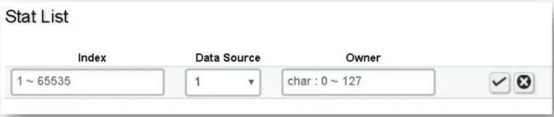
| Index | Enter the entry number for event. |
| Data Source | Select the data source from the port. |
| Owner | Enter the switch that defined the event. |
Click the Apply button √ to accept the changes or the Cancel button ✗ to discard them.
Event List
The Event List defines RMON events on the Switch.

| Index | Enter the entry number for event. |
| Event Type | Select the event type.Log: The event is a log entry.SNMP Trap: The event is a trap.Log & Trap: The event is both a log entry and a trap. |
| Community | Enter the community to which the event belongs. |
| Description | Displays the number of good broadcast packets received on the interface. |
| Last Time Sent | Displays the time that event occurred. |
| Owner | Enter the switch that defined the event. |
Click the Apply button √ to accept the changes or the Cancel button ✗ to discard them.
Event Log Table
From here, you can view specific event logs for the switch. Choose an event log you wish to view from the drop-down list.

Alarm List
You can configure network alarms to occur when a network problem is detected. Choose your preferences for the alarm from the drop-down boxes.
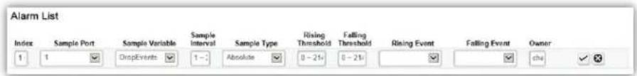
| Index | Enter the entry number for the Alarm List. |
| Sample Port | Select the port from which the alarm samples were taken. |
| Sample Variable | Select the variable of samples for the specified alarm sample. |
| Sample Interval Enter the alarm interval time. | |
| Sample Type | Select the sampling method for the selected variable and comparing the value against the thresholds.Absolute: Compares the values with the thresholds at the end of the sampling interval.Delta: Subtracts the last sampled value from the current value. |
| Rising Threshold | Enter the rising number that triggers the rising threshold alarm. |
| Falling Threshold | Enter the falling number that triggers the falling threshold alarm. |
| Rising Event | Enter the event number by the falling alarm are reported. |
| Falling Event | Enter the event number by the falling alarms are reported. |
| Owner | Enter the Switch that defined the alarm. |
Click the Apply button √ to accept the changes or the Cancel button ✗ to discard them.
History List

| Index Enter the entry number for the History List. | |
| Sample Port | Select the port from which the history samples were taken. |
| Bucket Requested | Enter the number of samples to be saved. The range is from 1 to 50. |
| Interval | Enter the time that samples are taken from the ports. The field range is from 1 to 3600. |
| Owner | Enter the RMON user that requested the RMON information. The range is from 0 to 32 characters. |
Click the Apply button √ to accept the changes or the Cancel button ✗ to discard them.
History Log Table
From here, you can view the History Index for history logs on the Switch. Select a history index to view from the drop-down box.

Statistics
From here, you can view all the RMON statistics of the Switch.
| Port | Drop Events | Octats | Pkts | Broadcast Pkts | Multicast Pkts | CRC Align Errors | Under Size Pkts | Over Size Pkts | Fragments | Jabbers | Collisions | Pkts 64 Octats | Pkts 85 to 127 Octats | Pkts 128 to 255 Octats | Pkts 256 to 511 Octats | Pkts 512 to 1023 Octats | Pkts 1924 to 1518 Octats |
| □ | |||||||||||||||||
| □ | 1 | 0 | 68425444 | 296812 | 6965 | 32978 | 0 | 0 | 0 | 0 | 0 | 119763 | 62107 | 32611 | 13092 | 40047 | 8002 |
| □ | 2 | 0 | 1183091729 | 5015632 | 373236 | 218717 | 0 | 0 | 0 | 0 | 0 | 457631 | 3352136 | 389564 | 147102 | 303969 | 365210 |
| □ | 3 | 0 | 0 | 0 | 0 | 0 | 0 | 0 | 0 | 0 | 0 | 0 | 0 | 0 | 0 | 0 | 0 |
| □ | 4 | 0 | 0 | 0 | 0 | 0 | 0 | 0 | 0 | 0 | 0 | 0 | 0 | 0 | 0 | 0 | 0 |
| □ | 5 | 0 | 0 | 0 | 0 | 0 | 0 | 0 | 0 | 0 | 0 | 0 | 0 | 0 | 0 | 0 | 0 |
| □ | 6 | 0 | 14543 | 113 | 62 | 51 | 0 | 199 | 0 | 0 | 0 | 195 | 20 | 60 | 28 | 5 | 0 |
| □ | 7 | 0 | 1422354322 | 5339283 | 13089 | 4190 | 42 | 4 | 0 | 0 | 5 | 0 | 1546001 | 2152386 | 412948 | 577706 | 86773 |
| □ | 8 | 0 | 1258810016 | 5403047 | 8130 | 83299 | 0 | 0 | 0 | 0 | 0 | 0 | 1630174 | 2170577 | 344589 | 454008 | 486857 |
| □ | 9 | 0 | 395187668 | 5954372 | 126364 | 115212 | 0 | 0 | 0 | 0 | 0 | 0 | 355586 | 2207222 | 259740 | 116842 | 75385 |
| □ | 10 | 0 | 1579921264 | 116886964 | 61419749 | 20739862 | 0 | 0 | 0 | 0 | 0 | 0 | 34970962 | 47545335 | 14504915 | 5037380 | 1427175 |
| □ | 11 | 0 | 0 | 0 | 0 | 0 | 0 | 0 | 0 | 0 | 0 | 0 | 0 | 0 | 0 | 0 | 0 |
| □ | 12 | 0 | 0 | 0 | 0 | 0 | 0 | 0 | 0 | 0 | 0 | 0 | 0 | 0 | 0 | 0 | 0 |
| Port | Indicates the specific port for which RMON statistics are displayed. |
| Drop Events | Displays the number of dropped events that have occurred on the port. |
| Octets Displays the number of octets received on the port. | |
| Pkts Displays the number of packets received on the port. | |
| Broadcast Pkts | Displays the number of good broadcast packets received on the port. This number does not include Multicast packets. |
| Multicast Pkts | Displays the number of good Multicast packets received on the port. |
| CRC & Align Errors | Displays the number of CRC and Align errors that have occurred on the port. |
| Undersize Pkts | Displays the number of undersized packets (less than 64 octets) received on the port. |
| Oversize Pkts | Displays the number of oversized packets (over 1518 octets) received on the port. |
| Fragments | Displays the number of fragments received on the port. |
| Jabbers | Displays the total number of received packets that were longer than 1518 octets. |
| Collisions | Displays the number of collisions received on the port. |
| Pkts of 64 Octets | Displays the number of 64-byte frames received on the port. |
| Pkts of 65 to 127 Octets | Displays the number of 65 to 127 byte packets received on the port. |
| Pkts of 128 to 255 Octets | Displays the number of 128 to 255 byte packets received on the port. |
| Pkts of 256 to 511 Octets | Displays the number of 256 to 511 byte packets received on the port. |
| Pkts of 512 to 1023 Octets | Displays the number of 512 to 1023 byte packets received on the port. |
| Pkts of 1024 to 1518 Octets | Displays the number of 1024 to 1518 byte packets received on port. |
Log
The Syslog protocol allows devices to send event notification messages in response to events, faults, or errors occurring on the platform as well as changes in configuration or other occurrences across an IP network to syslog servers. It then collects the event messages, providing powerful support for users to monitor network operation and diagnose malfunctions. A Syslog-enabled device can generate a syslog message and send it to a Syslog server.
Syslog is defined in RFC 3164. The RFC defines the packet format, content, and system log related information of Syslog messages. Each Syslog message has a facility and severity level. The Syslog facility identifies a file in the Syslog server. Refer to the documentation of your Syslog program for details. The following table describes the Syslog severity levels.
| Code | Severity | Description General Description | |
| 0 | EMERG S | System is unusable. | A "panic" condition usually affecting multiple apps/servers/sites. At this level it would usually notify all tech staff on call. |
| 1 | ALERT Action | must be taken immediately. | Should be corrected immediately, therefore notify staff who can fix the problem. An example would be the loss of a primary ISP connection. |
| 2 | CRIT Critical conditions. | Should be corrected immediately, but indicates failure in a secondary system, an example is a loss of a backup ISP connection. | |
| 3 | ERROR Error conditions. | Non-urgent failures, these should be relayed to developers or admins; each item must be resolved within a given time. | |
| 4 | WARNING | Warning conditions. | Warning messages, not an error, but indication that an error will occur if action is not taken, e.g. file system 85% full - each item must be resolved within a given time. |
| 5 | NOTICE Normal but significant condition. | Events that are unusual but not error conditions - might be summarized in an email to developers or admins to spot potential problems - no immediate action required. | |
| 6 | INFO Informational messages | Normal operational messages - may be harvested for reporting, measuring throughput, etc. - no action required. | |
Global Settings
From here, you can Enable or Disable the log settings for the Switch.
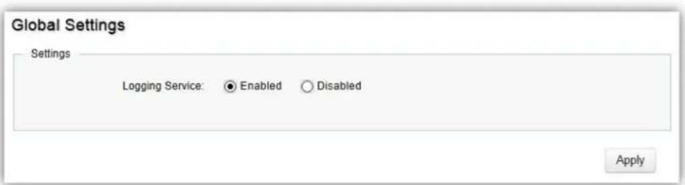
Click Apply to update the system settings.
Local Logging
The System Log is designed to monitor the operation of the Switch by recording the event messages it generates during normal operation. These events may provide vital information about system activity that can help in the identification and solutions of system problems.
The Switch supports log output to two directions: Flash and RAM. The information stored in the system's RAM log will be lost after the Switch is rebooted or powered off, whereas the information stored in the system's Flash will be kept effective even if the Switch is rebooted or powered off. The log has a fixed capacity; at a certain level, the Linksys Switch will start deleting the oldest entries to make room for the newest.
| Local Logging | ||||||||
| Target | EMERG | ALERT | CRIT | ERROR | WARNING | NOTICE | INFO | DEBUG |
| RAM | Yes | Yes | Yes | Yes | Yes | Yes | Yes | |
| Flash | Yes | Yes | Yes | Yes | Yes | Yes | Yes | |
Click the Apply button √ to accept the changes or the Cancel button ✗ to discard them.
Remote Logging
The internal log of the Switch has a fixed capacity; at a certain level, the Switch will start deleting the oldest entries to make room for the newest. If you want a permanent record of all logging activities, you can set up your syslog server to receive log contents from the Switch. Use this page to direct all logging to the syslog server. Click the Add button, define your syslog server, and select the severity level of events you wish to log.
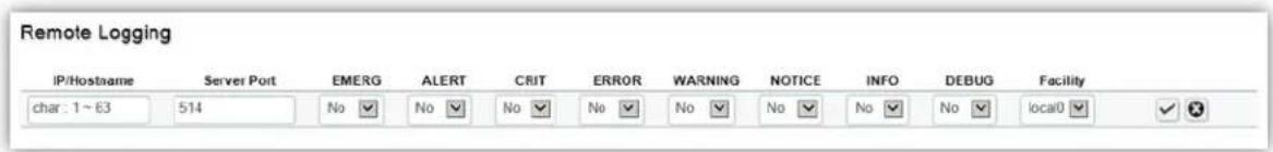
Click the Apply button √ to accept the changes or the Cancel button ✗ to discard them.
Log Table
This page displays the most recent records in the Switch's internal log. Log entries are listed in reverse chronological order (with the latest logs at the top of the list). Click a column header to sort the contents by that category.
Display logs in
- RAM: The information stored in the system's RAM log will be lost after the Switch is rebooted or powered off
- Flash: The information stored in the system's Flash will be kept effective even if the Switch is rebooted or powered off.
Type
- Switch: Display switch related logs.
• All: Display logs for both controller and switch.
Export: Click Export button to export the current buffered log to a .txt file.
Clear: Click Clear button to clear the buffered log in the system's memory.
Diagnostics
Cable Diagnostics
Cable Diagnostics helps you to detect whether your cable has connectivity problems provides information about where errors have occurred in the cable. The tests use Time Domain Reflectometry (TDR) technology to test the quality of a copper cable attached to a port. TDR detects a cable fault by sending a signal through the cable and reading the signal that is reflected back. All or part of the signal is reflected back either by cable defects or by the end of the cable when an issue is present. Cables are tested when the ports are in the down state, with the exception of the cable length test.
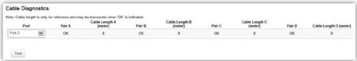
To verify accuracy of the test, it is recommended that you run multiple tests in case of test fault or user error.
Click Test to perform the cable tests for the selected port.
Ping Test
The Packet Internet Groper (Ping)Test allows you to verify connectivity to remote hosts. The Ping test operates by sending Internet Control Message Protocol (ICMP) request packets to the tested host and waits for an ICMP response. In the process it measures the time from transmission to reception and records any packet loss. Send a ping request to a specified IPv4 address. Check whether the Switch can communicate with a particular network host before testing.
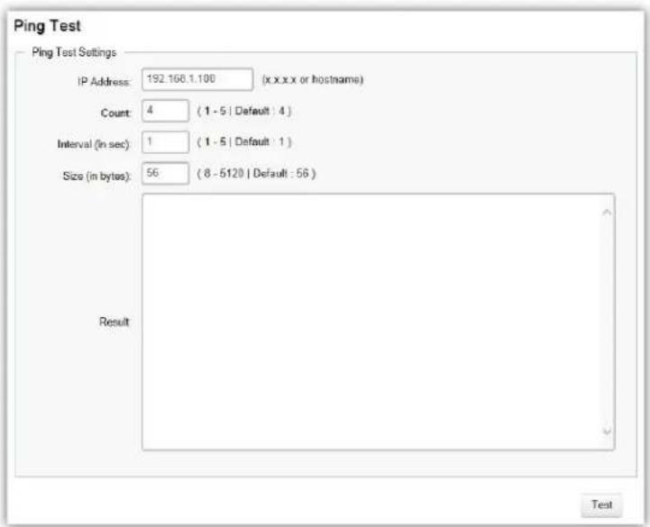
You can vary the test parameters by entering the data in the appropriate boxes. To verify accuracy of the test, it is recommended that you run multiple tests in case of a test fault or user error.
| IP Address | Enter the IP address or the host name of the station you want the Switch to ping to. |
| Count | Enter the number of ping to send. The range is from 1 to 5 and the default is 4. |
| Interval | Enter the number of seconds between pings sent. The range is from 1 to 5 and the default is 1. |
| Size | Enter the size of ping packet to send. The range is from 8 to 5120 and the default is 56. |
| Result | Displays the ping test results. |
Click Test to perform the ping test.
IPv6 Ping Test
Send a ping request to a specified IPv6 address. Check whether the Switch can communicate with a particular network host before testing.
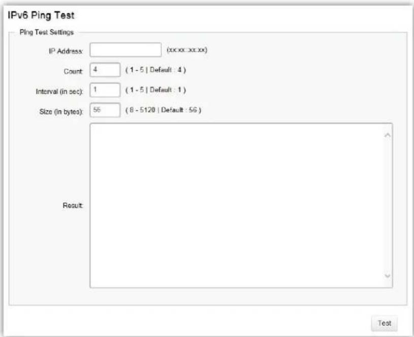
You can vary the test parameters by entering the data in the appropriate boxes. To verify accuracy of the test, it is recommended that you run multiple tests in case of a test fault or user error.
| IP Address | Enter the IPv6 address or the host name of the station you want the Switch to ping to. |
| Count | Enter the number of ping to send. The range is from 1 to 5 and the default is 4. |
| Interval | Enter the number of seconds between pings sent. The range is from 1 to 5 and the default is 1. |
| Size | Enter the size of ping packet to send. The range is from 8 to 5120 and the default is 56. |
| Result | Displays the ping test results. |
Click Test to perform the ping test.
Trace Route
The traceroute feature is used to discover the routes that packets take when traveling to their destination. It will list all the routers it passes through until it reaches its destination, or fails to reach the destination and is discarded. In testing, it will tell you how long each hop from router to router takes via the trip time of the packets it sends and receives from each successive host in the route.
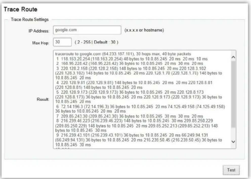
| IP Address | Enter the IP address or the host name of the station you wish the Switch to ping to. |
| Max Hop | Enter the maximum number of hops. The range is from 2 to 255 and the default is 30. |
| Result | Displays the trace route results. |
Click Test to initiate the trace route.
Maintenance
Maintenance functions are available from the maintenance bar located on the upper right corner of the user interface. Maintenance functions include saving configuration settings, upgrading firmware, resetting the configuration to factory default standards, rebooting the device, and logging out of the interface. The following represents the Maintenance menu bar.

Configuration Manager
The File Management feature is used for saving your current configuration to a file on your computer or a TFTP server, or to restore previously saved configuration settings to the Switch using a configuration file from your local drive or TFTP server. Click the Backup icon enters into the configuration manager function.
Configuration Manager
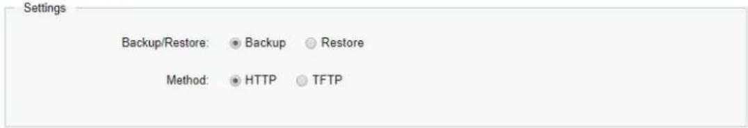
Apply
Click Apply to download configuration settings to your computer or a TFTP server, or to upload previously saved configuration file to the system.
Firmware Upgrade
Firmware Upgrade
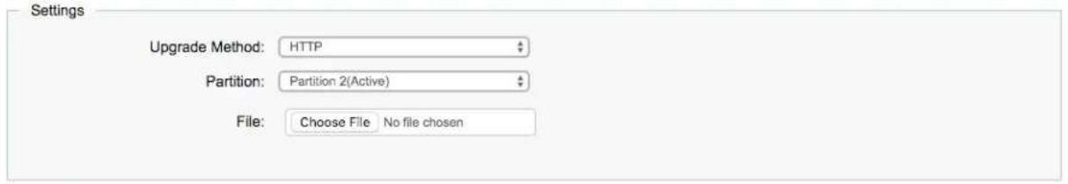
Apply
WARNING Backup your configuration before upgrading to prevent loss of settings information.
Note: The upgrade process may require a few minutes to complete. It is advised to clear your browser cache after upgrading your firmware.
Reset
Restore switch to system default.

Visit linksys.com/support for award-winning 24/7 technical support.
LINKSYS and many product names and logos are trademarks of the Belkin group of companies. Third-party trademarks mentioned are the property of their respective owners. Licenses and notices for third party software used in this product may be viewed here: http://support.linksys.com/en-us/license. Please contact http://support.linksys.com/en-us/gplcodecenter for questions or GPL source code requests.
© 2021 Linksys Holdings, Inc. and/or its affiliates. All rights reserved.
LNKPG-00782 Rev B01