HD-SDI DWC-HV421D - Security Camera Digital Watchdog - Free user manual and instructions
Find the device manual for free HD-SDI DWC-HV421D Digital Watchdog in PDF.


User questions about HD-SDI DWC-HV421D Digital Watchdog
0 question about this device. Answer the ones you know or ask your own.
Ask a new question about this device
Download the instructions for your Security Camera in PDF format for free! Find your manual HD-SDI DWC-HV421D - Digital Watchdog and take your electronic device back in hand. On this page are published all the documents necessary for the use of your device. HD-SDI DWC-HV421D by Digital Watchdog.
USER MANUAL HD-SDI DWC-HV421D Digital Watchdog
text_image
D TIR DW DIGITAL WATCHDOG Watchdog Style DW DIGITAL WATCHDOG Watchdog Style DW HDABOUT MANUAL
Before installing and using the camera, please read this manual carefully.
Be sure to keep it handy for future reference.
PRECAUTIONS
■ Do not open or modify.
■ Do not open the case except during maintenance and installation, for it may be dangerous and can cause damages.
■ Do not put objects into the unit.
- Keep metal objects and flammable substances from entering the camera.
It can cause fire, short-circuits, or other damages.
■ Be careful when handling the unit.
■ To prevent damages, do not drop the camera or subject it to shock or vibration.
■ Do not install near electric or magnetic fields.
■ Protect from humidity and dust.
■ Protect from high temperature.
■ Be careful when installing near the ceiling of kitchen or a boiler room, as the temperature may rise to high levels.
■ Cleaning:
To remove dirt from the case, moisten a soft cloth with a soft detergent solution and wipe.
■ Mounting Surface:
The material of the mounting surface must be strong enough to support the camera.
FCC COMPLIANCE
This equipment has been tested and found to comply with the limits for a Class B digital device, pursuant to part 15 of the FCC rules. These limits are designed to provide reasonable protection against harmful interference. when the equipment is operated in a residential environment. This equipment generates, uses, and radiates radio frequency energy; and if it is not installed and used in accordance with the instruction manual, it may cause harmful interference to radio communications.
WARNING: Changes or modifications are not expressly approved by the manufacturer.
TABLE OF CONTENTS
Introduction Features 4
Parts and Descriptions 5
Dimensions 6
Installation - - - - - - - - - - Included Accessories - - - - - - - - - - - - - 7
Easy Installations 8-13
Connecting to Monitors 14
Controlling the Camera's OSD Remotely- - - - - - - - - - - - 15
Adjusting the Camera'S Lens 16
Adjusting the 3-Axis Gimbal 17
Camera OSD Menu and Glossary 18-30
Troubleshooting 31
Warranty Information 32-33
Specifications 34-35
FEATURES\*
■ Sony 1/2.8" CMOS Sensor
- Highest Resolution 2.1 Megapixels
■ 720P / 1080P Mode Selectable
- 3.5\~16mm Auto-Focus Lens
■ 4.5X Optical Zoom
- Double Shutter WDR (Wide Dynamic Range) at 15fps
- 70ft Range IR with Intelligent Camera Sync [HV421TIR]
- Electronic Day and Night [HV421D]
■ True Day and Night [HV421TIR]
■ AGC / BLC / AWB
■ 3D DNR (3D Digital Noise Reduction)
- Digital Zoom (0\~112 level)
■ HME/ HLMSK (Highlight Masking Exposure)
- Mirror & Image Flip
■ Programmable Privacy Zone (30) & Motion Detection
- Dead Pixel Cancellation
■ 12VDC Support Only
■ Secondary Video-BNC Output
■ IP68 Certified (Waterproof)
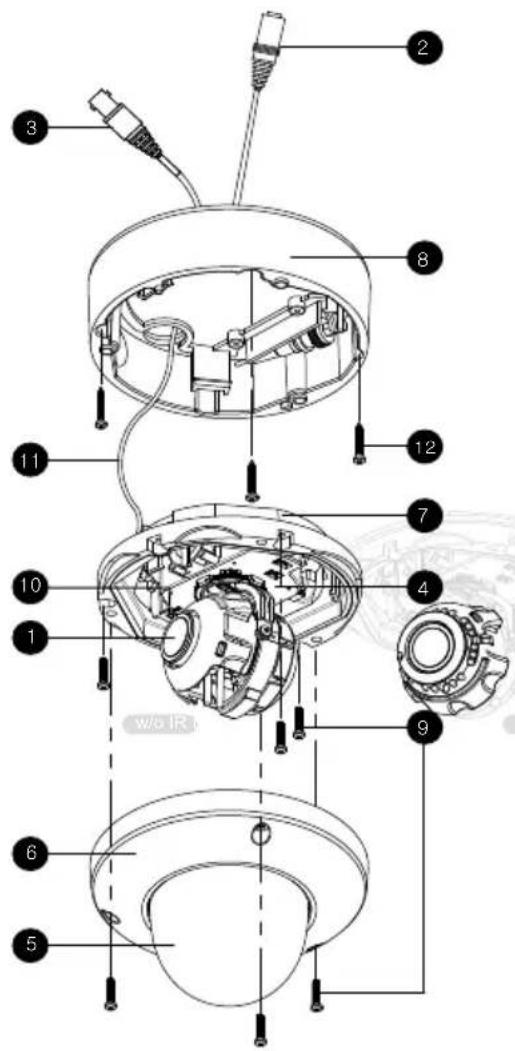
PART & DESCRIPTIONS\*
text_image
Technical diagram of a mechanical device with numbered components and wiring annotations1 Lens
2 Power input Connector 12VDC Voltage
3 BNC (HD-SDI) + RS485
4 Camera Control Board
5 Bubble Dome
6 Upper Case
7 Flush Mount Case
8 Surface Mount Case
9 Assembly Screws
8 - 32 x 0.75
10 2nd Video Connector
11 Safety Wire
12 Mounting Screws
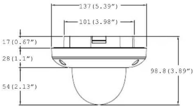
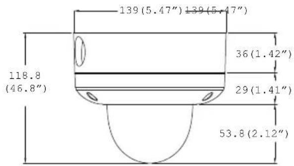
DIMENSIONS IN MILLIMETERS (IN)\*
Flush Mount
text_image
137 (5.39") 101 (3.98") 17 (0.67") 28 (1.1") 54 (2.13") 98.8 (3.89)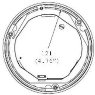
text_image
121 (4.76")Surface Mount
text_image
139 (5.47") 139 (5.47") 118.8 (46.8") 36 (1.42") 29 (1.41") 53.8 (2.12"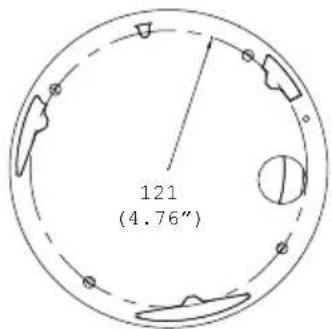
text_image
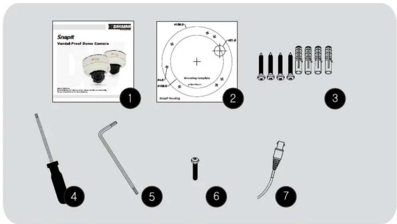
121 (4.76")INSIDE THE BOX\*
Included with Snapit Vandal Dome Camera
① User Manual
2 Mounting Template
3 4 Machine Screw and 4 Dry Wall Anchors
4 TORX-T20 Wrench
⑤ L-Wrench
6 TORX-T20 Bolt
7 Secondary Video-BNC Cable
text_image
Snapit Vandal-Proof Dome Camera 1 2 3 4 5 6 7 #138.0 #21.0 Mounting Template Snapit Hounding #4.5 #105.0SURFACE MOUNT INSTALLATION INSTRUCTIONS\*
natural_image
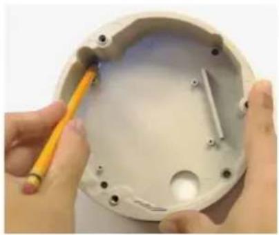
Close-up of hands installing or adjusting a white plastic enclosure with a yellow tool (no text or symbols visible)1 Use the camera's mounting template or your camera to mark the holes as required.
natural_image
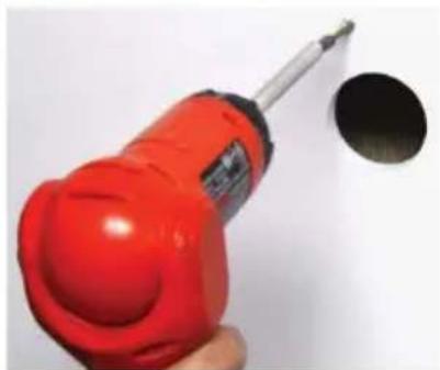
Hand holding a red soldering iron with a black hole, against a plain white background (no text or symbols visible)● Drill holes into the drywall and insert the drywall mounts into the holes.
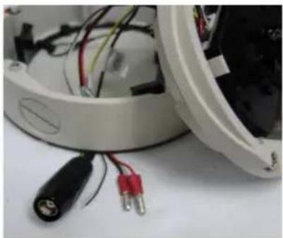
natural_image
Close-up of a white electronic device with wires and connectors, no visible text or symbols● Pull wires through and make connections.
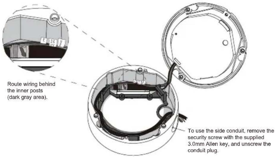
If you need to keep the wiring within the camera housing, refer to the diagram below.
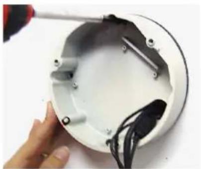
natural_image
Close-up of a hand using a power tool to install a white circular device with black cables (no text or symbols visible)4 Mount the surface mount base (junction box) to the wall.
text_image
Route wiring behind the inner posts (dark gray area). To use the side conduit, remove the security screw with the supplied 3.0mm Allen key, and unscrew the conduit plug.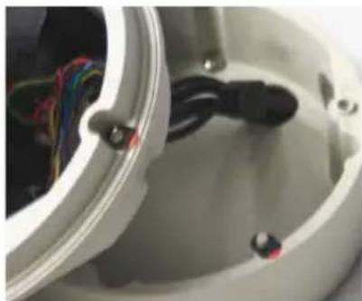
natural_image
Close-up of a white electronic device interior showing exposed wiring and black components (no text or symbols visible)5 Snap the camera module onto the base by aligning the red and black markings on the base and the camera module.
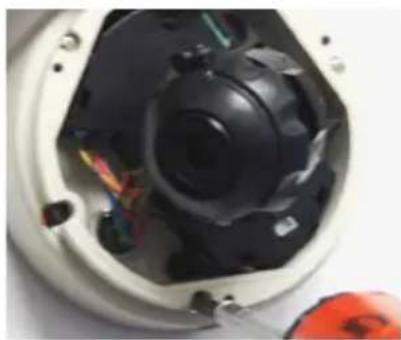
natural_image
Close-up of a mechanical device interior with visible internal components and wiring (no text or symbols)- Secure the three (3) assembly screws.
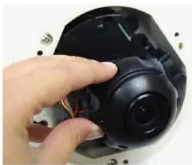
natural_image
Close-up of a hand holding a black camera lens with visible wiring, no text or symbols present- Adjust the camera's position by using the 3-Axis Gimbal.
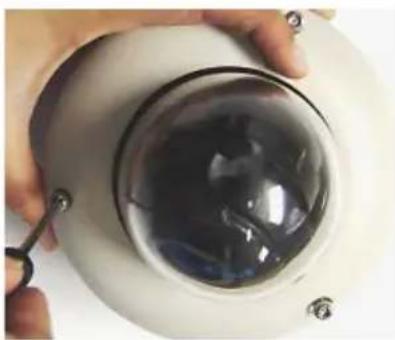
natural_image
Close-up of a hand holding a transparent dome-shaped object with a small metallic clip, no visible text or symbols.● Tighten the three locking screws in with the L-Wrench to secure the cover dome over the camera.
FLUSH MOUNT INSTALLATION INSTRUCTIONS\*
For a flush mount housing, detach the surface mount base, which is also known as the junction box, from the flush mount base.
Use the mounting template to mark the holes for the screws and a larger hole for the top extruded component of the flush mount base.
② The three assembly screws (ST4X35) fixed to the flush mount base should be used to mount the camera to the surface of the wall or ceiling.
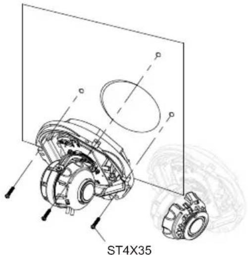
text_image
ST4X35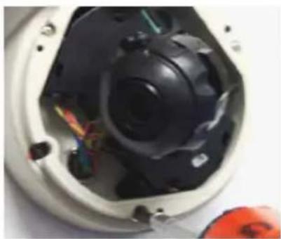
natural_image
Interior view of a device housing with exposed black components and wiring (no visible text or symbols)34 Secure the three (3) assembly screws.
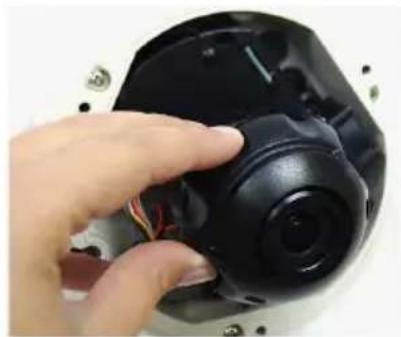
natural_image
Close-up of a hand holding a black mechanical component with wires, no visible text or symbols- Adjust the camera's position by using the 3-Axis Gimbal.
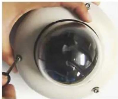
natural_image
Close-up of a hand holding a transparent cylindrical container with liquid, no visible text or symbols● Tighten the three locking screws in with the L-Wrench to secure the cover dome over the camera.
WALL MOUNT INSTALLATION INSTRUCTIONS (optional)\*
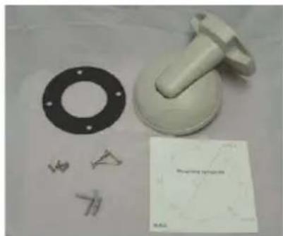
natural_image
Product photo of a white plastic mechanical component with flange, bolt holes, and small handwritten marks (no text or symbols visible)Check to see all parts are in the box.
natural_image
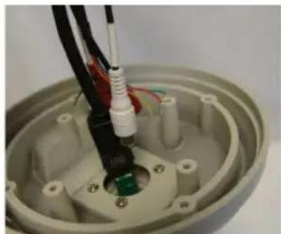
Close-up of a mechanical assembly with exposed wiring and a green component inside a gray housing (no text or symbols visible)● Insert the wires from the camera through the wall mount housing.
natural_image
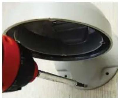
Close-up of a white and red handheld device with a black lid, mounted on a wooden surface (no visible text or symbols)- Use the mounting template to make pilot holes. Use the dry wall anchors and woods screws to attach the assembly.
natural_image
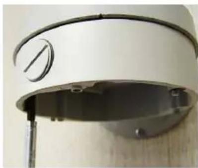
Close-up of a white cylindrical device with a circular dial and mounting bracket, mounted on a wooden surface (no visible text or symbols)49 Attach the camera's surface mount base (junction box) to the wall mount.
natural_image
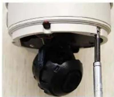
Close-up of a mechanical device with a black cushioned part inserted, mounted on a metal rod (no visible text or symbols)- Connect all cables and snap the camera module onto the base.
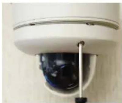
natural_image
Close-up of a security camera with a mounted sensor and lens (no visible text or symbols)- Adjust the camera and secure the dome cover over the camera module.
Note: Mount sold separately.
PENDANT MOUNT INSTALLATION INSTRUCTIONS (optional)\*
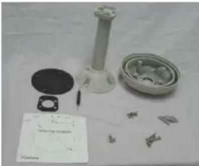
natural_image
Assorted mechanical components including a cylindrical component, flange, and parts on a white surface (no visible text or symbols)Check to see all parts are in the box.
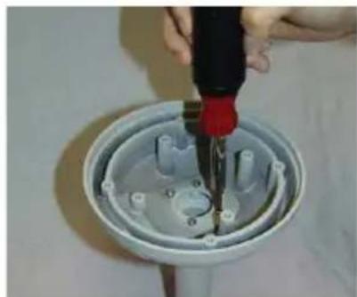
natural_image
Close-up of a hand using a screwdriver to adjust or install a component in a plastic housing (no text or symbols visible)- Attach the top shield to the pendant mount.
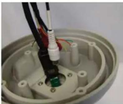
natural_image
Close-up of a mechanical assembly with exposed wiring and a green component inside a circular housing (no text or symbols visible)● Run all necessary cables from the ceiling to the mount.
natural_image
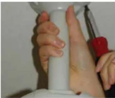
Close-up of hands holding a white cylindrical object with a red tool, no visible text or symbols49 Use the mounting template to make pilot holes. Use the dry wall anchors and wood screws to attach the assembly to the wall.
natural_image
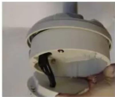
Close-up of a hand holding a white plastic cap with a black plastic clip inside (no text or symbols visible)- Connect all cables and verify camera is operating properly.
natural_image
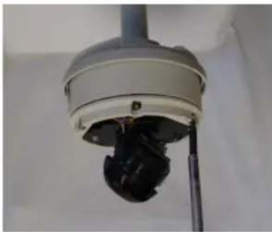
Close-up of a mounted security camera with visible lens and antenna (no text or symbols)- Attach the camera to the ceiling mount and secure the dome cover properly.
Note: Mount sold separately.
CORNER MOUNT INSTALLATION INSTRUCTIONS (optional)\*
natural_image
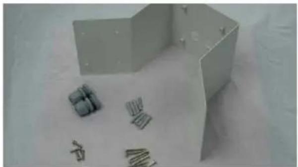
White 3D geometric shapes on a light surface, including a cube and scattered small objects (no text or symbols visible)① Check to see all parts are in the box.
natural_image
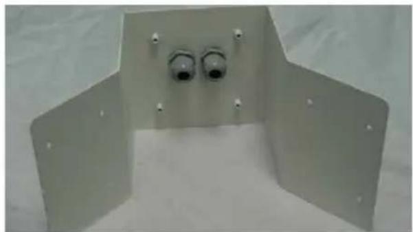
Metal bracket with two circular ports and mounting holes, no visible text or symbols2 Attach the two compression fittings to the corner bracket.
natural_image
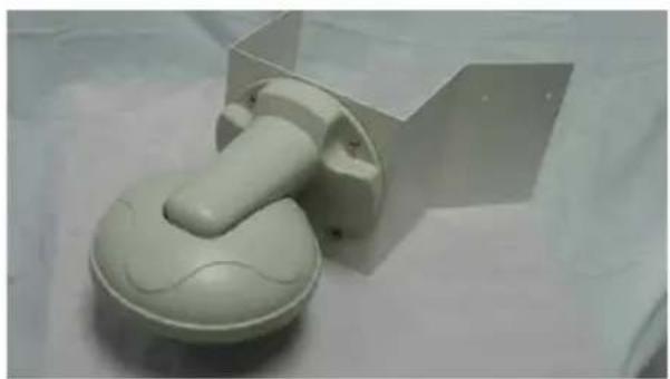
White plastic mechanical component with a curved handle and base, placed on a plain surface (no text or symbols visible)3 Attach the wall mount bracket to the corner mount using the machine screws.
natural_image
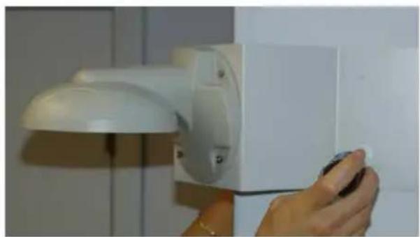
Hand holding a white lamp attached to a wall-mounted device (no visible text or symbols)4 Mount the camera assembly to the corner of the wall, using wall mount anchors and machine screws.
Note: Mount sold separately.
CONNECTING TO MONITORS\*
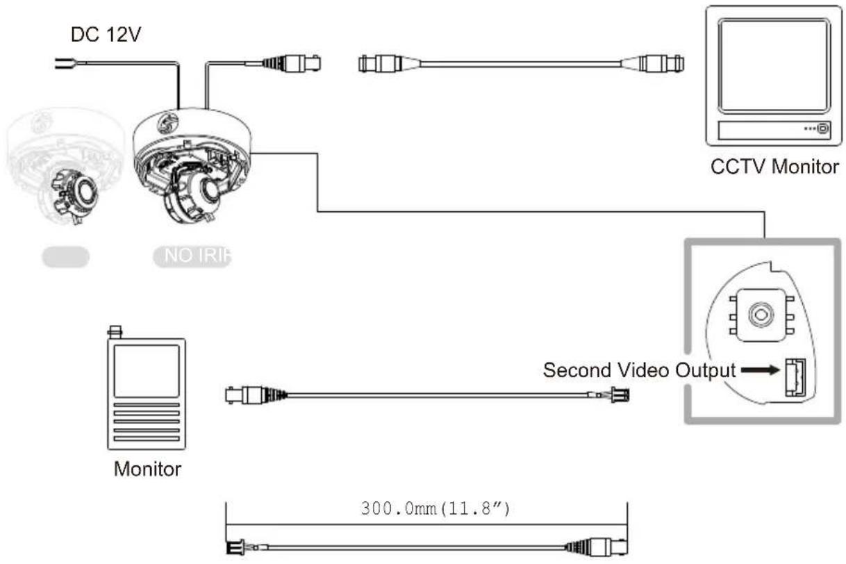
Use the diagram below to connect to a Monitor or CRT Monitor properly.
text_image
DC 12V CCTV Monitor NO IRIF Monitor Second Video Output 300.0mm (11.8")Power Connection: 12VDC Voltage.
All cameras are equipped with a second video output for on-site configuration.
CONTROLLING THE CAMERA'S OSD REMOTELY
DWC-HV421D and DWC-HV421TIR, combined with Digital Watchdog's VMAX HD DVR offer the unique feature of controlling the camera's OSD menu, focus and zoom all from the DVR with no additional cables other than the BNC cable.
To setup the camera for remote DVR controlling, make sure these steps are followed:
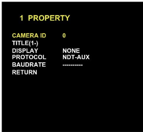
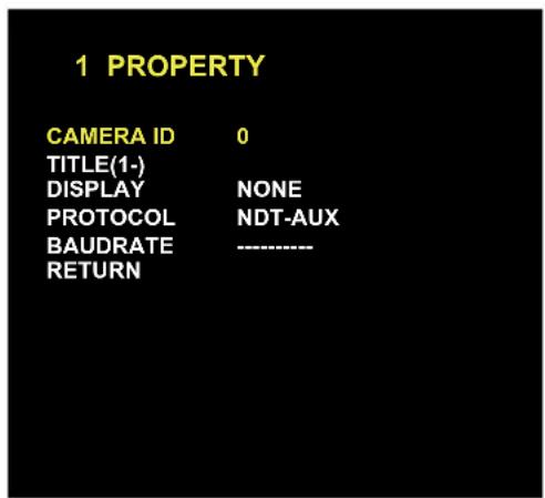
- Go to the camera's OSD menu and select 'Property'. Make sure the camera is set to NDT-AUX Protocol.
- If you have multiple DWC-HD cameras you want to connect to the same VMAX HD, be sure to assign each camera a different ID. See page 19 for more information.
- On the DVR side, go to the main menu and select- Device- PTZ. Enter the channel of the camera you wish to setup. Make sure the ID you set in the DVR corresponds with e ID you have assigned the camera.
- Select "FASTRAXII COAX" in the DVR.
- Please refer to the DVR's manual for additional information on setup and camera control.
text_image
1 PROPERTY CAMERA ID 0 TITLE(1-) DISPLAY NONE PROTOCOL NDT-AUX BAUDRATE ---- RETURNADJUSTING THE CAMERA LENS\*
text_image
UP DOWNAdjusting Auto Focus Lens
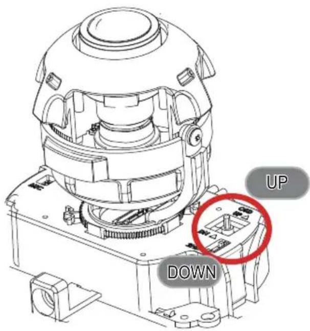
If pushing the OSD joystick to 'UP', the lens will start zoom-in. If pushing the OSD joystick to 'DOWN', the lens will start zoom-out. If you keep pushing the joystick, zoom in/out will be continuously operated.
When you find the right angle, take off your finger from the joystick and wait. The focus will be automatically adjusted.
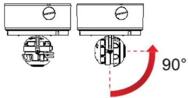
ADJUSTING THE 3-AXIS GIMBAL\*
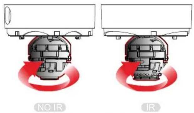
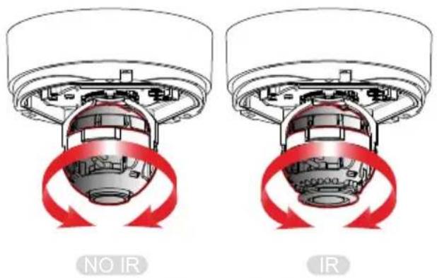
The Gimbal mechanism yields maximum rotation and placement as show below.
text_image
NO IR IRRotation 360^
text_image
NO IR IRPanning 360°
text_image
90°NOIR
Tilting 90°
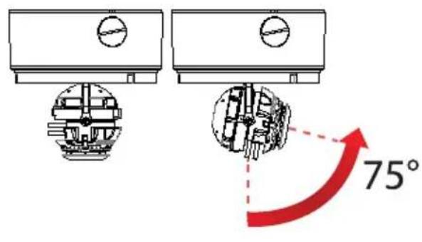
text_image
75°IR Tilting 75°
MODULE OSD MENU*
| PROPERTY EXPOSURE LENS | ||
| CAMERA ID0~255TITLEDISPLAYNON, ID., TITLEPROTOCOLNDT-AUXBAUDRATERETURN | BRIGHTNESS0~20SHUTTERAUTO, MANUAL (1/30~1/60000)DSSOFF, x2, x3, x4AGC0~20RETURN | LENS TYPEMANUAL, DC, AFMODEOUTDOOR,INDOOR/FLK,Deblur120,Deblur240OPTIC ZOOM TELE, WIDEFOCUS MODE MANUAL, AUTOFOCUSING FAR, NEARTIMER OFF, 1~10minTDN SYNC OFF, ONRETURN |
| FUNCTION IMAGE WDR/BLC | ||
| DZOOM0~112AWBAUTO, AUTO_H, AUTO_L, PRESET,AUTO-ext, MANUAL(Kelvin, R-Gain, B-Gain)PRIVACYOFF, ON(30 masks, setup position, size, & color)DNROFF, LOW, MIDDLE, HIGHMOTIONOFF, ON(Resolution, Sensitivity)RETURN | CHROMA 0~20SHARPNESS 0~10MIRROR ON, OFFFLIP ON, OFFE-Edge ON, OFFHLMASK OFF, ON(Level 0~20, Color)CONTRAST NORMAL, HIGH, HIGHESTCOLOR SET Color1, Color2, Color3HUE CONTROL R-GAIN, B-GAINRETURN | MAX DR OFF, ONMODE OFF, BLC, WDRWDR_WGT 0~9BLC OSD OFF, ONBLC POS-X 0~20BLC POS-Y 0~20BLC SIZ-X 0~20BLC SIZ-Y 0~20RETURN |
| DAYNIGHT SET UP EXIT | ||
| TDN MODEAUTO, COLOR, BW, LEDBW to C0~10C to BW0~10CDS SETBW Low, BW HighRETURN | DETECT DET OFF, ON (00~99, aa~ff)2.0M MODE 1080P, 720P720P MODE 60/50FPS, 30/25FPSLANGUAGE ENG, GER, CHNTDN TEST TEST OFF, TEST ONFACTORY SET YES, NOFREQ 60Hz, 50HzTYPE DOME, BOX, BULLETFW_LOCK ON,OFFRETURN | EXITNo Save, Yes SaveRETURN |
PROPERTY
text_image
1 PROPERTY CAMERA ID 0 TITLE(1-) DISPLAY NONE PROTOCOL NDT-AUX BAUDRATE ---- RETURNCAMERA ID
0\~255 You can define the camera's ID no. from 0\~255. For OSD control of multiple cameras, make sure to assign a different ID to each camera. See page 11 for more information.
TITLE
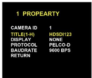
(1-) You can give the camera a unique title 8 symbols long. To set the camera's title, select from the following symbols: 0\~9, A\~Z, and space.
Example: HDSDI123.
TITLE (1-H) H
TITLE (2-D) HD
TITLE (3-S) HDS
TITLE (4-D) HDSD
TITLE (5-1) HDSDI
TITLE (5-1) HDSDI1
TITLE (6-2) HDSDI12
TITLE (8-3) HDSDI123
text_image
1 PROPEARTY CAMERA ID 1 TITLE(1-H) HDSDI123 DISPLAY NONE PROTOCOL PELCO-D BAUDRATE 9600 BPS RETURNDISPLAY
NONE, ID, TITLE
You can select to display the camera's ID or title on the video by selecting the appropriate option.
PROTOCOL
NDT-AUX
If you are connecting the camera to Digital Watchdog's VMAXHD DVR, use the default Protocol- NDT-AUX. See page 11 for more information.
BAUDRATE
9600 is default.----
RETURN
EXPOSURE
text_image
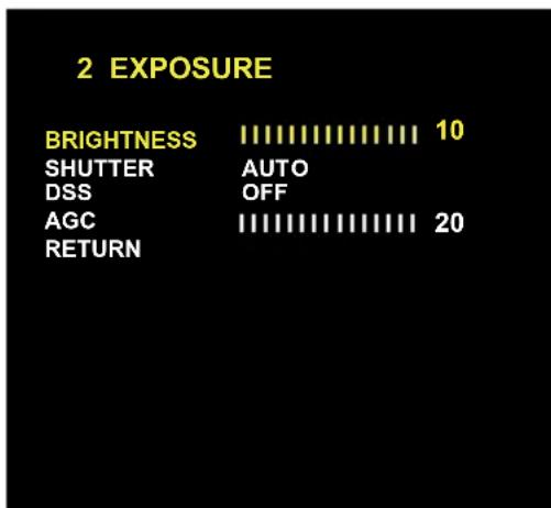
2 EXPOSURE BRIGHTNESS 10 SHUTTER AUTO DSS OFF AGC 20 RETURNBRIGHTNESS
0\~20 You can adjust the brightness of the image.
The higher the number, the brighter the image.
Default is 10.
SHUTTER
AUTO The shutter's speed adjusts automatically based on the light available.
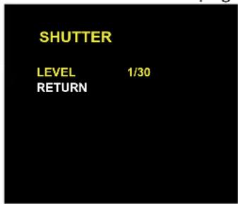
MANUAL The shutter speed can be adjusted between 1/30 \~ 1/60000. Available options depend on the Lens-Mode. See page 17 for more information.
text_image
SHUTTER LEVEL 1/30 RETURN| LENS MODE | Available Shutter Speed |
| OUTDOOR | 1/30~1/60000 |
| INDOOR/FLK | 1/30 Fixed |
| DEBLUR120 | 1/30~1/120 |
| DEBLUR240 | 1/30~1/240 |
DSS (Digital Slow Shutter)
OFF, x2, x3, x4
The default is OFF.
Choose x2,3, or x4 for slower shutter.
AGC (Auto Gain Control)
0\~20
Auto Gain Control automatically adjusts the video gain to enhance picture brightness in low light conditions. The higher number the better sensitivity. The default is 20.
RETURN
LENS
text_image
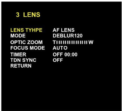
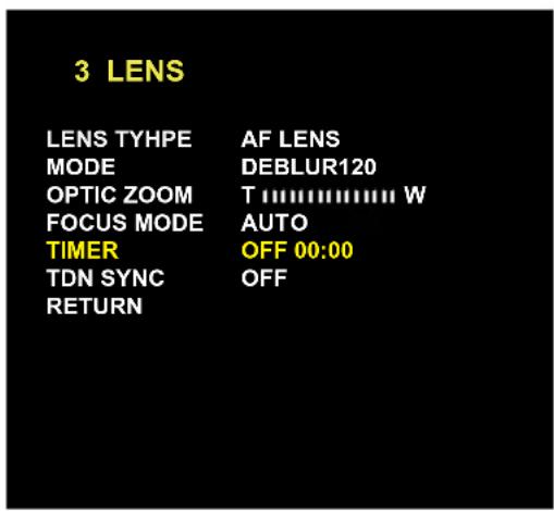
3 LENS LENS TYHPE AF LENS MODE DEBLUR120 OPTIC ZOOM TIIIIIIIIIIIIIIW FOCUS MODE AUTO TIMER OFF 00:00 TDN SYNC OFF RETURNLENS TYPE
AF LENS
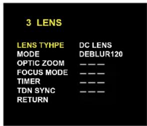
DC LENS
MANUAL
Auto Focus Lens.
Auto-iris Varifocal lens.
Manual iris or Fixed board lens.
text_image
3 LENS LENS TYHPE DC LENS MODE DEBLUR120 OPTIC ZOOM ———— FOCUS MODE ———— TIMER ———— TDN SYNC ———— RETURNIf DC or Manual modes are selected, the following menu options will be disabled:
OPTIC ZOOM
FOCUS MODE
TIMER
TDN SYNC
MODE
OUTDOOR
INDOOR/FLK
DEBLUR120
DEBLUR240
Offers full range of eletric shutter speed from 1/30\~1/60000.
Sets the shutter speed to 1/30. Use this Lens mode to avoid color rolling.
Offers electric shutter speed from 1/30\~1/120.
Offers electric shutter speed from 1/30\~1/240.
Both DEBLUR120, DEBLUR240 help avoid motion blur in low light conditions.
OPTIC ZOOM
Zoom Range is adjustable from Tele to Wide.
Available only if Lens Mode is set to AF. To adjust the optical zoom, move the joystick left and right until the desired zoom is achieved.
Once the desired zoom is selected, the camera will auto-focus.
See page 13 for zoom setup outside the OSD menu.
LENS
FOCUS MODE
AUTO
When using Auto Focus Lens, Focus is adjusted automatically. If AUTO is selected, the camera will adjust the focus after every optical zoom adjustment.
You can also set the camera to automatically adjust the focus based on a timer, from once every minute, up to every ten (10) minutes.
MANUAL
If you want to adjust the focus manually, select MANUAL.
The TIMER menu will be replaced by the FOCUSING menu.
The FOCUSING menu allows you to adjust the focus using the far/ near indicators.
Use the josytick to achieve the desired focusing level.
text_image
3 LENS LENS TYHPE AF LENS MODE DEBLUR120 OPTIC ZOOM T W FOCUS MODE AUTO TIMER OFF 00:00 TDN SYNC OFF RETURN
text_image
3 LENS LENS TYHPE AF LENS MODE DEBLUR120 OPTIC ZOOM T:\\......\\ W FOCUS MODE MANUAL FOCUSING N < - > F TDN SYNC OFF RETURNTDN SYNC
OFF / ON
If selected, the focus will adjust automatically whenever the camera changes from B/W to Color and back.
FUNCTION

text_image
4 FUNCTION DZOOM 0 AWB AUTO PRIVACY OFF DNR MIDDLE MOTION OFF RETURNDZOOM
0\~112 Digital Zoom function zooms to the center of the image by default. set the zoom level from 0\~112.
AWB
White Balance is automatically adjusted. AUTO
AUTO_H White Balance is automatically adjusted when the Color temperature is high.
AUTO_L White Balance is automatically adjusted when the Color temperature is low.
White Balance is fixed with current setting.PRESET White Balance is manually adjusted.MANUAL
AUTO-ext Select AUTO-ext mode when using external lighting like a halogen.
text_image
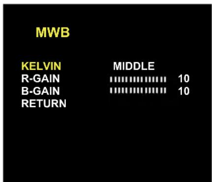
MWB KELVIN MIDDLE R-GAIN 10 B-GAIN 10 RETURNIf MANUAL mode is selected, define the following menu options:
KELVIN The color temperature level that will trigger the AWB. Select from LOW / MIDDLE / HIGH
R-GAIN Adjusts the amount of red in the image. Select from 0\~20. The higher the number, the image will appear red. The lower the number, the image will appear green.
B-GAIN Adjusts the amount of blue in the image. Select from 0\~20. The higher the number, the image will appear blue. The lower the number, the image will appear yellow.
FUNCTION
PRIVACY
OFF / ON
You can hide some parts of the screen for privacy purposes. A total of 30 privacy masks are available.
| PRIVACY | |
| ZONE NO | 0~29 |
| ZONE OP | ON/OFF |
| X-POS | 0~57 |
| Y-POS | 0~31 |
| X-SIZ | 0~60 |
| Y-SIZ | 0~34 |
| COLOR | CYN, GRN, MAG, RED,BLU, BLK, WHT, YEL |
| TRANS | 0~4 |
| RETURN | |
| 0~29ZONE NOZone Display. ON/OFFZONE OPX-Position (0~57)X-POSY-Position (0~31)Y-POSX-Size (0~60)X-SIZY-Size (0~34)Y-SIZ | |
| COLOR | Privavy Masking Zone Color - CYN, GRN, MAG, RED, BLU, BLK, WHT, YEL |
| TRANS | Transparency (0~4)Lower number means more transperant. |
To setup a Privacy Zone:
- Go to function menu, and select Privacy ON. Enter the sub-menu. (All 30 masks will appear in their default position).
- Select the zone number you want to adjust. Select from 0 (top left mask) to 29 (bottom right mask).
- You can select to show or hide a specific mask by selecting the mask number, going to ZONE OP and selecting ON to display, OFF to hide. (Note: to hide all but one mask, go to each mask number except the one you want to display and select OFF).
- Use the X-POS to adjust the horizontal location of the mask. Select 0 (far left) \~ 57 (far right).
- Use the Y-POS to adjust the vertical location of the mask. Select 0 (top of the screen) \~ 31 (bottom of the screen).
- Use the X-SIZ to adjust the width of the mask. Select 0 (no display) \~ 60 (screen-wide).
- Use the Y-SIZ to adjust the length of the mask. Select 0 (no display) \~ 34 (screen-tall).
- If necessary, adjust the color of the mask from the 8 options available.
- You can adjust the transparency of the mask by selecting 0 (only the outline of the mask is visible) \~ 4 (the entire mask is visible). NOTE: if the mask's transparency is set to 0, playback video will display the mask as an outline only, and the image behind the mask WILL be recorded.
FUNCTION
DNR
Digital Noise Reduction reduces the noise/distortion on the screen in low light conditions, allowing a clear image at night.
Sellect OFF / LOW / MIDDLE / HIGH.
MOTION
OFF/ON
If selecting ON, define the following menu:
RESOLUTION
Define the size an area with motion has to be to trigger the camera's motion detection.
The higher the number, the smaller the area with motion has to be to trigger the camera's motion detection.
SENSITIVITY
Define the level of motion necessary to trigger the camera's motion detection.
The higher the number, the more delicate motion can be to trigger the camera's motion detection.
MOTION
RESOLUTION
5
SENSITIVITY
5
RETURN
IMAGE
text_image
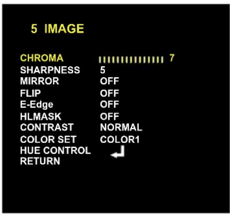
5 IMAGE CHROMA 7 SHARPNESS 5 MIRROR OFF FLIP OFF E-Edge OFF HLMASK OFF CONTRAST NORMAL COLOR SET COLOR1 HUE CONTROL RETURNCHROMA
0\~20
Chroma sets the quality of the color that embraces both hue and saturation. White, black and grays have 0 chroma. The higher numbers accentuate the brighter colors in the image. Default is 7.
SHARPNESS
0\~10
Sets the image's sharpness. The higher the number, the sharper lines and details will appear in the image. However, the sharper the image, the more digital noise will be visible.
MIRROR
Flips the image horizontally. OFF is the default.ON/OFF
FLIP
Flips the image vertically. OFF is the default.ON/OFF
E-Edge
Edge enhancement. If enabled, edges and fine lines will appear sharper in the image. ON/OFF
HLMASK
OFF
High Lux Masking masks ares in the image that are overly exposed to light.
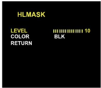
ON
If ON is selected, you can adjust the masking level and color. adjust the level from 0 (only areas with a lot of light will be masked)\~10. You can also modify the mask's color from the available 8 options - BLK, WHT, YEL, CYN, GRN, MAG, RED, and BLU
text_image
HLMASK LEVEL COLOR RETURN 10 BLKRETURN
IMAGE
CONTRAST
NORMAL/ HIGH/ HIGHEST You can adjust the contrast level - Normal, High, and Highest.
COLOR SET
COLOR 1,2,3
Color 1 is the default. If the color reproduction on the monitor is not to your satisfactory, try changing the color mode to Color2 or Color3.
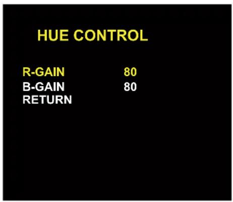
HUE CONTROL
R-GAIN
50 \~180. Adjust the amount of red color in the image. The higher the number, the bolder warm colors will appear.
B-GAIN
50 \~180. Adjust the amount of blue color in the image. The higher the number, the bolder cool colors will appear.
text_image
HUE CONTROL R-GAIN 80 B-GAIN 80 RETURNRETURN
WDR/BLC
| 6 WDR/BLC | |
| MAX DR | OFF |
| MODE | OFF |
| WDR_WGT | 5 |
| BLC OSD | OFF |
| BLC POS-X | 5 |
| BLC POS-Y | 5 |
| BLC SIZ-X | 9 |
| BLC SIZ-Y | 9 |
| RETURN | |
MAX-DR (Digital Wide Dynamic Range)
OFF/ ON
Digital Wide Dynamic Range provides clear images when a strong backlighting is present.
MODE
OFF/ BLC/ WDR
BLC - Back Light Compensation. See information below.
WDR - Wide Dynamic Range (If selected, camera will automatically adjust to 15 frames per second)
WDR\_WGT
0\~9
Enables the camera to capture clear images in the same frame, even when there are both very bright and very dark areas in the same field.
The higher number, the wider the dynamic range. The default is 5.
BLC OSD
OFF / ON
Backlight compensation prevents subjects in defined areas from appearing too dark when backlighting is present.
If ON is selected, BLC Zone size and location is adjustable.
BLC POS-X
0\~20
Adjusts BLC Horizontal Position.
BLC POS-Y
0= far right side of the screen. 20= far left side of the screen.
0\~20
Adjusts BLC Vertical Position.
BLC SIZ-X
0= bottom of the screen. 20= top of the screen.
0\~20
Adjusts the width of the BLC Masking area.
BLC SIZ-Y
0= invisible. 20= screen-wide.
0\~20
Adjusts the length of the BLC Masking area.
0= invisible. 20= screen-tall.
RETURN
DAY&NIGHT
7 DAY&NIGHT
TDN
BW to C
C to BW
CDS SET
RETURN
COLOR
5
5
BW LOW
TDN MODE
AUTO
The camera switches between day and night automatically depending on the level of light.
The camera always stays in day mode (Color).COLOR
The camera always stays in night mode (B/W).BW
LED
LED mode is supported when using external LED light.
BW to C
0\~9
Adjusts the light level threshold at which the camera switches from night (BW) to day (Color). High number means the higher light level. This number should be LOWER than the value of Color to B/W.
C to BW
0\~9
Adjusts the light level threshold at which camera switches from day (Color) to night (BW). High number means the lower light level. This number should HIGHER than the value of B/W to Color.
CDS SET
BW LOW
Adjusts the filter change signal level when using IR LEDs.
BW HIGH
BW HIGH is default.
RETURN
SETUP
text_image
8 SETUP DEFECT DET OFF 2.0M MODE 1080P 720P MODE 60/50FPS LANGUAGE ENG TDN TEST TEST OFF FACTORY SET YES GREQ 60HZ(NTSC) TYPE BOX F/W LOCK ON RETURNDEFECT DET
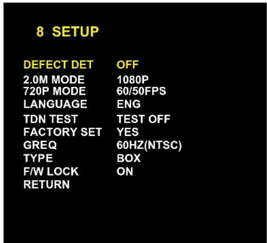
OFF / ON
Dead Pixel Cancellation automatically removes defective pixels in real time.
Consult your installer for setup and additional information.
2.0M MODE
1080P / 720P
The camera offers the selection of 2 resolutions: 1080P and 720P.
720P MODE
60/50FPS
If resolution 720P is selected, the camera will automatically adjust to 30/25 frames per second. You can also select 60/50FPS if applicable.
30/25FPS
LANGUAGE
ENG/ GER/
Select a language for the OSD menu. Select: English, German, Chinese.
CHN
TDN TEST
TEST OFF/ TEST ON
True Day & Night test examines the TDN filter in the camera.
FACTORY SET
YES/ NO
Consult your installer for setup and additional information.
FREQ
60HZ, 50HZ
NO is the default. If YES is selected, the camera's settings will return to factory default. Note that all personalized settings will be lost.
Selct 60HZ for NTSC, or 50HZ for PAL.
TYPE
DOME, BOX, BULLET
Set by manufacturer in the factory. Please do not change.
FW LOCK
OFF/ON
Firmware Lock Function. This feature is set by default to OFF. It is not recommended to select 'ON'.
RETURN
TROUBLESHOOTING
Before sending your camera for repair, check the following or contact our technical specialist.
FOR NO VIDEO
Check the coaxial cable and make sure it is connected securely.
Check the lens' iris adjustment at the camera's OSD menu.
Check the power supply and make sure the camera has the proper voltage and current.
FOR OUT-OF-FOCUS VIDEO
Check the clear dome cover and the lens for dirt or fingerprints. Use a soft cloth and gently clean. Check the lens' manual focal and zoom adjustment. The use of a field test monitor is recommended.
WARRANTY INFORMATION\*
Digital Watchdog (referred to as “the Warrantor”) warrants the Digital Watchdog Camera against defects in materials or workmanship as follows:
LABOR: For the initial five (5) years and one (1) year on IR LED from the original purchase date, if the camera is determined to be defective, the Warrantor will repair or replace the unit with a new or refurbished product at its option at no charge.
PARTS: In addition, the Warrantor will supply replacement parts for the initial five (5) years and one (1) year on IR LED.
To obtain warranty or out of warranty service, please contact a Technical Support Representative at 1-866-446-3595 Monday through Friday from 8:30AM to 8:00PM Eastern Standard Time.
A purchase receipt or other proof of the original purchase date is required before warranty service is rendered. This warranty only covers failures due to defects in materials and workmanship which arise during normal use. This warranty does not cover damage which occurs in shipment or failures which are caused by products not supplied by the Warrantor or failures which result from accident, misuse, abuse, neglect, mishandling, misapplication, alteration, modification, faulty installation, set-up adjustments, improper antenna, inadequate signal pickup, maladjustment of consumer controls, improper operation, power line surge, improper voltage supply, lightning damage, rental use of the product or service by anyone other than an authorized repair facility or damage that is attributable to acts of God.
LIMITS AND EXCLUSIONS\*
There are no express warranties except as listed. The warrantor will not be liable for incidental or consequential damages (including damage to recording media without limitation) resulting from the use of these products or arising out of any breach of the warranty. All express and implied warranties, including the warranties of merchantability and fitness for particular purpose, are limited to the applicable warranty period set forth above.
Some states do not allow the exclusion or limitation of incidental or consequential damages, or limitatons on how long an implied warranty lasts, so the exclusions or limitations listed above may not apply to you. This warranty gives you specific legal rights, and you may also have other rights that vary from state-to-state.
If the problem is not handled to your satisfaction, then write to the following address:
Digital Watchdog, Inc.
ATTN: RMA Department
5436 W. Crenshaw Street
Tampa, FL 33634
Service calls which do not involve defective materials or workmanship as determined by the Warrantor, in its sole discretion, are not covered. Costs of such service calls are the responsibility of the purchaser.
SPECIFICATIONS*
| VIDEO | |
| Image Sensor 1/2.8" CMOS Sensor | |
| Total Pixels 2000 (H) x 1241 (V) | |
| Synchronization | Internal |
| Horizontal Resolution 2.1 Megapixels (1920 x 1080) at 30fps | |
| Minimum Illumination F1.6 (30IRE): 0.1 Lux [Color]F1.6 (30IRE): 0.01 Lux [B&W] | |
| S/N Ratio 50dB (AGC off) | |
| Video Output HD-SDI, CVBS Analog | |
| LENS | |
| Focal Length 3.5-16mm | |
| Lens Type Auto Focus | |
| IR Distance 70ft Range IR | |
| OPERATIONAL | |
| Brightness | 0-20 |
| Shutter | AUTO / MANUAL / DEBLUR120 / DEBLUR 240 / OUTDOOR |
| Digital Slow Shutter OFF / X2 / X3 / X4 | |
| Auto Gain Control 0-20 | |
| Lens Type MANUAL / DC / AF | |
| Lens Mde OUTDOOR/ INDOOR FLK/ DEBLUR120/ DEBLUR240 | |
| Auto White Balance | AUTO / AUTO_H / AUTO_I / PRESET / MANUAL / AUTO_EXT |
| Privacy Zones OFF / ON (30 Programmable Zones) | |
SPECIFICATIONS*
| OPERATIONAL | |
| Digital Noise Reduction OFF / LOW / MIDDLE / HIGH | |
| Digital zoom | 1~112 |
| Chroma | 0-20 |
| Sharpness | 0-10 |
| Mirror & Flip OFF / ON | |
| Highlight Mask OFF / ON | |
| WDR / BLC OFF / WDR / BLC | |
| Language ENGLISH / CHINESE / GERMAN | |
| ENVIRONMENTAL | |
| Operating Temperature -10 | °C ~ 50°C (14°F ~ 122°F) |
| Operating Humidity Less than 90% (Non-Condensing) | |
| Storage Temperature -20 | °C ~ 70°C (-4°F ~ 158°F) |
| IP Rating IP68 (Protects against dust and immersion beyond 3ft.) | |
| ELECTRICAL | |
| Power Requirement DC12V Only (10V ~ 16V) | |
| Power Consumption 2.0W, 166.7mA / LED ON 3.5W, 291.7mA | |
| MECHANICAL | |
| Housing Material Aluminum | |
| Dome Cover Material Polycarbonate | |
| Dimensions | ∅139 X 118.8 mm (∅5.47 X 4.7 in) |
| Weight | 2.05 lbs |
*Specification is subject to change without prior notice.

text_image
DW•DIGITAL WATCHDOGEverything's Digital
5436 W Crenshaw St. Tampa, FL 33634
Tel: 866-446-3595 / 813-888-9555
Fax:813-888-9262
www.Digital-Watchdog.com
technicalsupport@dwcc.tv
Technical Support Hours : Monday-Friday
8:30am to 8:00pm EST