
EMC Data Domain 9300 - NAS DELL - Free user manual and instructions
Find the device manual for free EMC Data Domain 9300 DELL in PDF.


| Product Type | Enterprise NAS & Deduplication Appliance |
| Brand | Dell EMC |
| Model | Data Domain 9300 |
| Form Factor | 5U Rackmount |
| Dimensions (H x W x D) | 8.7 x 44.5 x 76.2 cm (3.4 x 17.5 x 30 in) |
| Weight (Max Configuration) | Approximately 68 kg (150 lbs) |
| Processor | Dual Intel Xeon Scalable (16 cores each) |
| System Memory | 512 GB DDR4 ECC |
| Storage Capacity (Raw) | Up to 1.15 PB (288 x 4 TB HDDs) |
| Deduplication Ratio | Up to 55:1 (typical backup workloads) |
| Network Interfaces | 4 x 10GbE SFP+, 4 x 25GbE SFP28 |
| Supported Protocols | NFS, CIFS/SMB, FC, iSCSI, DD Boost |
| Power Supply | Dual 2400W Hot-Plug Redundant (100-240V AC) |
| Power Consumption (Typical) | 1500 W |
| Cooling | 8 Hot-Swappable Fans (N+1 Redundant) |
| Management Interface | Web GUI (HTTPS), CLI (SSH), REST API |
| Built-in Data Protection | Inline deduplication, compression, encryption (AES-256) |
| Replication | Asynchronous, synchronous (optional), DD Cloud Tier |
| Operating Temperature | 10°C to 35°C (50°F to 95°F) |
| Storage Drive Types | 4 TB NL-SAS 7.2K RPM (SAS/SATA) |
| Warranty | 3 Years Hardware (extendable) |
| Available Options | Expansion shelf (DS60), SSD cache, encryption key management |
Frequently Asked Questions - EMC Data Domain 9300 DELL
User questions about EMC Data Domain 9300 DELL
0 question about this device. Answer the ones you know or ask your own.
Ask a new question about this device
Download the instructions for your NAS in PDF format for free! Find your manual EMC Data Domain 9300 - DELL and take your electronic device back in hand. On this page are published all the documents necessary for the use of your device. EMC Data Domain 9300 by DELL.
USER MANUAL EMC Data Domain 9300 DELL
Dell EMC Data Domain DD6300, DD6800, and DD9300 Systems
Version 6.1
Hardware Overview and Installation Guide
302-003-008
REV 06
Copyright © 2016-2017 Dell Inc. and its subsidiaries. All rights reserved.
Published June 2017
Dell believes the information in this publication is accurate as of its publication date. The information is subject to change without notice.
THE INFORMATION IN THIS PUBLICATION IS PROVIDED "AS-IS." DELL MAKES NO REPRESENTATIONS OR WARRANTIES OF ANY KIND WITH RESPECT TO THE INFORMATION IN THIS PUBLICATION, AND SPECIFICALLY DISCLAIMS IMPLIED WARRANTIES OF MERCHANTABILITY OR FITNESS FOR A PARTICULAR PURPOSE. USE, COPYING, AND DISTRIBUTION OF ANY DELL SOFTWARE DESCRIBED IN THIS PUBLICATION REQUIRES AN APPLICABLE SOFTWARE LICENSE.
Dell, EMC, and other trademarks are trademarks of Dell Inc. or its subsidiaries. Other trademarks may be the property of their respective owners. Published in the USA.
Dell EMC
Hopkinton, Massachusetts 01748-9103
1-508-435-1000 In North America 1-866-464-7381
www.DellEMC.com
CONTENTS
Figures 5
Tables 7
Revision history 9
Chapter 1 Planning and Site Preparation 11
Tools and supplies needed....12
Safety information.... 12
Chapter 2 Data Domain DD6300, DD6800, and DD9300 Hardware Overview
Front panel....16
DD6300 front panel....16
DD6800 front panel....16
DD9300 front panel....17
Front LED indicators.... 18
Back panel....19
DD6300 rear SSDs.... 19
Rear LED indicators....19
I/O modules....22
Storage capacity.... 26
DD6300 storage capacity.... 26
DD6800 storage capacity.... 26
DD9300 storage capacity.... 27
DD6300 system features....28
DD6300 system specifications.... 29
Internal system components....30
DIMMs overview....30
DD6800 system features.... 31
DD6800 system specifications.... 32
Internal system components....33
DIMMs overview....33
DD9300 system features.... 34
DD9300 system specifications.... 35
Internal system components....36
DIMMs overview....36
Chapter 3 Install the System in the Rack 39
Unpack the system....40
Rails and cable management assembly.... 40
Identify the rack location to install the system.... 41
Install the rails.... 41
Install the DD6300, DD6800, or DD9300 system into a rack.... 43
Installing the cable management assembly (CMA).... 45
Installing the expansion shelves into the racks....46
Chapter 4 Connect Cables and Power on 49
Connecting ES30 shelves....50
DD6300....51
DD6800 and DD9300 (single node, DD Cloud Tier, or ERSO)......52
DD6800 and DD9300 (HA or HA with DD Cloud Tier)....54
Connecting DS60 shelves....57
DD6300....58
DD6800 and DD9300....59
DD6800 and DD9300 with HA....61
DD6800 with DD Cloud Tier....62
DD6800 and with HA and DD Cloud Tier....64
DD9300 with DD Cloud Tier or HA and DD Cloud Tier.... 65
DD6800 and DD9300 with ERSO....67
Connecting the HA interconnect.... 69
Installing the front bezel....70
Connect data cables....70
Power on all systems....71
Chapter 5 Configure System for Use 73
Enable administrative communication....74
Accepting the End User License Agreement (EULA).... 75
Run the configuration wizard....75
Configuring the network.... 75
Configuring additional system parameters.... 77
Configure HA....78
FIGURES
1 Warning about lifting the system....13
2 Front LED indicators.... 18
3 Rear LED indicators.... 19
4 I/O module Power/Service LED location....21
5 Onboard network port LEDs.... 22
6 I/O module slot numbering.... 22
7 CPU and memory locations.... 30
8 CPU and memory locations....33
9 CPU and memory locations.... 36
10 Warning about lifting the system.... 40
11 Cable management assembly (CMA)....41
12 Warning about lifting the system.... 43
13 Service tag (components removed for clarity)...... 45
14 Installing the CMA on the rack....45
15 Adjusting the CMA depth.... 46
16 DD6300 with ES30 shelves.... 52
17 DD6800 and DD9300 with ES30s, single node, DD Cloud Tier, or ER....54
18 DD6800 and DD9300 with ES30s and HA or HA with DD Cloud Tier.... 56
19 HA interconnect....70
FIGURES
TABLES
1 Document revision history....9
2 DD6300 AIO capacity....16
3 DD6300 AIO configuration.... 16
4 DD6300 AIO expanded configuration.... 16
5 DD6800 DLH SSD requirements....17
6 DD6800 DLH configuration drive layout.... 17
7 DD6800 DLH expanded configuration drive layout.... 17
8 DD9300 DLH SSD requirements....17
9 DD9300 DLH configuration drive layout.... 17
10 DD9300 DLH expanded configuration drive layout.... 17
11 Front LEDs....18
12 DD6300 I/O slot module mapping....23
13 DD6800 and DD9300 I/O module slot mapping.... 23
14 I/O module slot population rules.... 24
15 DD6300 storage capacity.... 26
16 DD6800 storage capacity.... 27
17 DD9300 storage capacity.... 27
18 DD6300 system features.... 28
19 DD6300 system specifications.... 29
20 System operating environment....29
21 DD6300 memory DIMM configuration.... 30
22 Memory locations - CPU 0....30
23 Memory locations - CPU 1....31
24 DD6800 system features....31
25 DD6800 system specifications.... 32
26 System operating environment....32
27 DD6800 memory DIMM configuration.... 33
28 Memory locations - CPU 0....33
29 Memory locations - CPU 1....34
30 DD9300 system features.... 34
31 DD9300 system specifications.... 35
32 System operating environment....35
33 DD9300 memory DIMM configuration.... 36
34 Memory locations - CPU 0.... 36
35 Memory locations - CPU 1.... 37
36 Cables for primary node to ES30 shelf loop....50
37 Cables for standby node to ES30 shelf loop.... 50
38 ES30 to ES30 cable options....51
39 Primary node cabling instructions....55
40 Standby node cabling instructions....55
42 Primary node cabling instructions.... 61
43 Standby node cabling instructions....61
44 Primary node cabling instructions....64
45 Standby node cabling instructions.... 64
46 Primary node cabling instructions....65
47 Standby node cabling instructions....66
48 Communications settings....74
TABLES
Revision history
Table 1 Document revision history
| Revision | Date Document | part # Software version | Description | |
| 06 June 2017 | 302-003-008 6.1 | Editorial revisions. | ||
| 05 April 2017 | 302-003-008 6.0 | Editorial revisions. | ||
| 04 January | 2017 302-003-008 | 6.0 Added heat | dissipation (BTU/hr) to the system specifications. | |
| 03 December | 2016 302-003-008 | 6.0 Editorial revisions. | ||
| 02 October | 2016 302-003-008 | 6.0 Editorial revisions. | ||
| 01 October | 2016 302-003-008 | 6.0 Initial publication. |
Revision history
CHAPTER 1
Planning and Site Preparation
- Tools and supplies needed....12
- Safety information....12
Tools and supplies needed
These tools and supplies may be helpful for the installation and setup tasks for Data Domain systems.
• Null modem cable (DB-9 female to female), plus spare
- USB-to-DB-9 serial (male connector) converter cable if the laptop does not have a serial port, plus spare
- Power adapter, C13 to NEMA 5–15 (if based in North America), or a power cord for your laptop power adapter with a C13 plug, so that you can power your laptop from a rack PDU
• Antistatic wrist strap and conductive foam pad
- Screwdrivers:
■ Phillips #2 with a 12 in. or longer blade
■ Phillips #2 (standard-length blade)
Phillips #1
■ Flat head 3/16 in.
- Flat head 1/4 in.
■ Torx T10
- Flashlight
- Needle nose pliers
• Diagonal wire cutters (for cutting tie wraps)
• 2 GB or greater USB flash memory drive
• Tie wraps (4 in. and 8 in.) - (recommended) Roll of 5/8 inch Velcro cable tie material (3M Scotchmate SJ-3401 or similar)
Safety information
CAUTION
- If the system is used in a manner that is not specified by the manufacturer, the protection that is provided by the equipment may be impaired.
- The RJ45 sockets on the motherboard, PCI cards, or I/O modules are for Ethernet connection only and must not be connected to a telecommunications network.
Review this list of important safety recommendations.
- All plug-in modules and blank plates are part of the fire enclosure and must be removed only when a replacement can be added immediately. The system must not be run without all parts in place.
- DD6300, DD6800, and DD9300 systems must be operated only from a power supply input voltage range of 200–240 VAC and 50–60 Hz. The ES30 and FS15
shelves use 100–240 VAC and 50–60 Hz. DS60 shelves use 200–240 VAC and 50–60 Hz.
• Each component is intended to operate with all working power supplies installed.
- Provide a suitable power source with electrical overload protection.
- A safe electrical earth connection must be provided to each power cord. Check the grounding of the power sources before applying power.
- The plug on each power supply cord is used as the main device to disconnect power from the system. Ensure that the socket outlets are located near the equipment and are easily accessible.
- Permanently unplug the unit if you think it is damaged in any way and before moving the system. DD6300, DD6800, and DD9300 systems include two power supplies. To remove system power completely, disconnect both power supplies.
- The power connections must always be disconnected before removal or replacement of a power supply module from the system.
• A faulty power supply module must be replaced within 24 hours.
- Do not lift system components by yourself. DD6300, DD6800, and DD9300 systems weigh up to 80 lbs (36.29 kg) and an ES30 expansion shelf weighs up to 68 lbs (30.8 kg). A DS60 shelf weighs up to 225 lbs (102 KG)
CAUTION
Data Domain systems are heavy. Use at least two people or a mechanical lift to move any system.
- Do not lift an expansion shelf by the front handles on any modules. The handles are not designed to support the weight of the populated shelf.
- To comply with applicable safety, emission, and thermal requirements, covers must not be removed and all bays must be fitted with plug-in modules.
- Once removed from the shipping box, it is ok to lift the system or the chassis
Figure 1 Warning about lifting the system

- To prevent the rack from becoming top-heavy, load the rack with storage shelves beginning at the bottom and the system in the designated location.
- Data Domain recommends that you wear a suitable antistatic wrist or ankle strap for ESD protection. Observe all conventional ESD precautions when handling plug-in modules and components.
Planning and Site Preparation
CHAPTER 2
Data Domain DD6300, DD6800, and DD9300 Hardware Overview
- Front panel....16
- Back panel....19
• Storage capacity....26 - DD6300 system features.... 28
- DD6300 system specifications....29
- Internal system components....30
- DD6800 system features....31
- DD6800 system specifications....32
- Internal system components....33
- DD9300 system features....34
- DD9300 system specifications....35
- Internal system components.... 36
Front panel
The front panel contains 12 slots for a mix of 4 TB hard disk drives (HDDs) and 800 GB solid state drives (SSDs). The exact layout of the drives, and the types of drives used varies depending on the specific system model.
Note
Configurations that do not fill all 12 drive slots use filler panels in the empty slots to maintain proper air flow inside the chassis.
DD6300 front panel
DD6300 All-in-One (AIO) systems have one of the following front panel drive configurations to host the DD OS boot drives, and provide storage for customer data:
Note
Upgrading a base configuration to an expanded configuration provides less capacity than a factory-built expanded configuration.
Table 2 DD6300 AlO capacity
| Configuration Installed | drives Usable internal | capacity |
| DD6300 base configuration | Seven 4 TB HDDs 14 TB | |
| DD6300 expanded configuration (factory) | Twelve 4 TB HDDs 34 TB | |
| DD6300 expanded configuration (upgrade) | Seven 4 TB HDDs + Five 4 TB HDDs 22 TB |
Table 3 DD6300 AIO configuration
| Slot 0: HDD 1 Slot 1: HDD 2 Slot 2: HDD 3 Slot 3: HDD 4 | |
| Slot 4: HDD 5 Slot 5: HDD 6 Slot 6: HDD 7 Slot 7: Filler | |
| Slot 8: Filler Slot 9: Filler Slot 10: Filler Slot 11: Filler |
Table 4 DD6300 AlO expanded configuration
| Slot 0: HDD 1 Slot 1: HDD 2 Slot 2: HDD 3 Slot 3: HDD 4 | |
| Slot 4: HDD 5 Slot 5: HDD 6 Slot 6: HDD 7 Slot 7: HDD 8 | |
| Slot 8: HDD 9 Slot 9: HDD 10 Slot 10: HDD 11 Slot 11: HDD 12 |
DD6800 front panel
DD6800 Dataless Head (DLH) systems have one of the following front panel drive configurations to host the DD OS boot drives and provide metadata caching on SSD:
Table 5 DD6800 DLH SSD requirements
| Configuration Number of SSDs | |
| DD6800 2 | |
| DD6800 expanded 4 | |
| NoteSSDs are not RAID-protected. | |
Table 6 DD6800 DLH configuration drive layout
| Slot 0: HDD 1 Slot 1: HDD 2 Slot 2: HDD 3 Slot 3: HDD 4 | |
| Slot 4: SSD 1 Slot 5: SSD 2 Slot 6: Filler Slot 7: Filler | |
| Slot 8: Filler Slot 9: Filler Slot 10: Filler Slot 11: Filler |
Table 7 DD6800 DLH expanded configuration drive layout
| Slot 0: HDD 1 Slot 1: HDD 2 Slot 2: HDD 3 Slot 3: HDD 4 | |
| Slot 4: SSD 1 Slot 5: SSD 2 Slot 6: SSD 3 Slot 7: SSD 4 | |
| Slot 8: Filler Slot 9: Filler Slot 10: Filler Slot 11: Filler |
DD9300 front panel
DD9300 Dataless Head (DLH) systems have one of the following front panel drive configurations to host the DD OS boot drives and provide metadata caching on SSD:
Table 8 DD9300 DLH SSD requirements
| Configuration Number of SSDs | |
| DD9300 5 | |
| DD9300 expanded 8 | |
| NoteSSDs are not RAID-protected. | |
Table 9 DD9300 DLH configuration drive layout
| Slot 0: HDD 1 Slot 1: HDD 2 Slot 2: HDD 3 Slot 3: HDD 4 | |
| Slot 4: SSD 1 Slot 5: SSD 2 Slot 6: SSD 3 Slot 7: SSD 4 | |
| Slot 8: SSD 5 Slot 9: Filler Slot 10: Filler Slot 11: Filler |
Table 10 DD9300 DLH expanded configuration drive layout
| Slot 0: HDD 1 Slot 1: HDD 2 Slot 2: HDD 3 Slot 3: HDD 4 | |
| Slot 4: SSD 1 Slot 5: SSD 2 Slot 6: SSD 3 Slot 7: SSD 4 | |
| Slot 8: SSD 5 Slot 9: S$D 6 Slot 10: SSD 7 Slot 11: SSD 8 |
Front LED indicators
The front of the DD6300, DD6800, and DD9300 systems contain 12 disk drive status LEDs that are normally blue, and blink when there is activity on the disk. The LEDs are shaped like triangles, and the apex of the triangle points left or right, indicating that disk's status. If the disk drive has a failure, the disk's status LED turns from blue to amber, indicating that a drive must be replaced.
The front also contains two system status LEDs. A blue system power LED is present that is on whenever the system has power. An amber system fault LED is also present that is normally off and lit amber whenever the chassis or any other FRU in the system requires service.
Figure 2 Front LED indicators
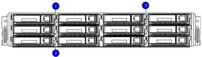
- System service LED
- Drive activity/service LED
- System power LED
Table 11 Front LEDs
| Name Color Purpose | ||
| System power LED Blue Indication that the system has | power. | |
| System service LED Amber Normally off; is lit amber | whenever the SP or any other FRU (except disk drives) in the system requires service. | |
| Drive activity/Service LED Blue /Amber | Lit blue when the drive is powered.Blinks blue during drive activity.Lit solid amber when a disk needs service. | |
Back panel
The back panel of the DD6300/DD6800/DD9300 chassis contains the following components:
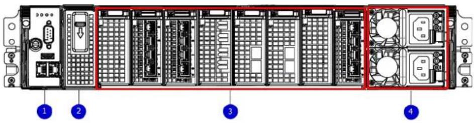
- Management panel
- Two 2.5" SSD slots labeled 0 and 1 (populated on DD6300 only)
- I/O module slots
- Power supply modules
DD6300 rear SSDs
The D6300 system uses one or two 800 GB SSDs mounted at the rear of the chassis for metadata caching:
| Configuration | Number of SSDs SSD location | |
| DD6300 1 SSD slot 0 | ||
| DD6300 expanded 2 SSD slots | 0 and 1 | |
| NoteSSDs are not RAID-protected. | ||
Rear LED indicators
Figure 3 Rear LED indicators
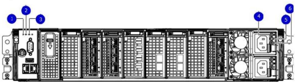
- Do not remove LED
- SP service LED
- System power LED
- AC power good LED
- DC power good LED
Figure 3 Rear LED indicators (continued)
6. Power supply fault LED
| Name of LED Location | Color Definition | ||
| "Do not remove" LED U | Upper left-most part of rear chassis | White This LED is lit during system BIOS and BMC firmware updates and indicates that the SP should not be removed from the chassis, nor should system power be removed. | |
| SP service LED To the right of "Do not remove" LED | Amber | Solid amber - SP or a FRU inside the SP requires serviceBlinking amber - blink rate reflects one of the following is bootingBIOS - 1/4 HzPOST - 1 HzOS - 4 Hz | |
| Drive Power/Activity LEDa | Left LED on the SSD Blue Lit blue when the | drive is powered.Blinks during drive activity. | |
| Drive Fault LEDa | Right LED on the SSD Amber Lit solid amber when a drive needs service. | ||
| System power LED Right-most LED on the management panel | Blue SP has good, stable power | ||
| PSU FRU LED - AC Good | Top LED on power supply | Green AC input is as expected | |
| PSU FRU LED - DC Good | Middle LED on power supply | Green DC output is as expected | |
| PSU FRU LED - Attention | Bottom LED on power supply | Amber PSU has encountered a fault condition | |
a. The SSD is only present on DD6300 systems.
Figure 4 I/O module Power/Service LED location
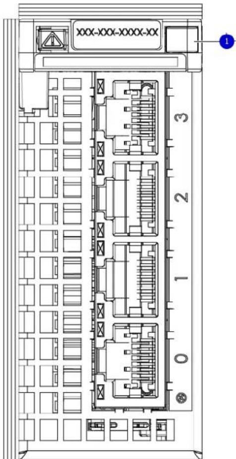
- I/O module power/service LED
| Name of LED Location | Color Definition | ||
| I/O module FRU LED - Figure 4 on page 21 | Ejector handle of I/O modules | Green/Amber | • Green - I/O module has power and is functioning normally• Amber - I/O module has encountered a fault condition and requires service |
| I/O port status LED (SAS, Fibre Channel, and optical networking I/O modules only) | One LED per I/O module port | Blue Lit when port is | enabled. May flash if SW "marks" the port. ^a |
a. For RJ45 networking ports, the standard green link and amber activity LEDs are used.
Figure 5 Onboard network port LEDs
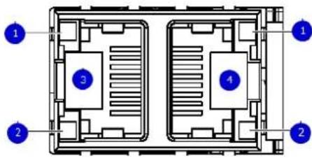
- Network port link LED
- Network port activity LED
- Dedicated IPMI port BMC0A
- Management interface EthMa
| Name of LED Location | on Color Definition | ||
| Onboard network portLED - Link LED Figure5 on page 22 | Top LED on network port | Green | Lit when there is a link at 1000BaseT and 100BaseT speedsOff when the link speed is 10BaseTor there is no link |
| Onboard network portLED - Activity LED | Bottom LED on network port | Amber Blinks when there istraffic on the port | |
I/O modules
I/O module slot numbering
The eight I/O module slots are enumerated as Slot 0 (on the left when viewed from the rear) through Slot 7. Ports on an I/O module are enumerated as 0 through 3, with 0 being on the bottom.
Figure 6 I/O module slot numbering
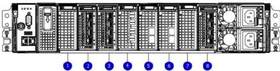
- Slot 0
- Slot 1
- Slot 2
- Slot 3
- Slot 4
- Slot 5
- Slot 6
8. Slot 7
Since DD6300, DD6800, and DD9300 is a data backup appliance, it is only supported in fixed configurations. The fixed configurations define the exact slots into which the I/O modules may be inserted. The processors directly drive the eight I/O module slots, meaning all slots are full performance.
The non-optional SAS, NVRAM, and 10GBaseT I/O modules are allocated to fixed slots. The optional Host Interface I/O modules are used for front end networking and Fibre Channel connections. The quantity and type of these I/O modules is customizable, and there are many valid configurations.
DD6300 slot map
Slot 0, Slot 1, Slot 2 (except when it is marked "Reserved") are populated with the required I/O modules and are not optional. I/O module slots 3-7 contain optional Host Interface I/O modules and can contain specific I/O modules or no I/O modules at all.
Table 12 DD6300 I/O slot module mapping
| Tier Slot 0 Slot 1 Slot 2 | Slot 3 Slot | 4 Slot 5 Slot | 6 Slot 7 | ||||
| AIO Expanded N | VRAM8g Model3 | Quad Port10 GBase-T | Reserved (Optional)Quad Port10GbE SR, Quad Port10 GBase-T, or Dual Port 16Gbps Fibre Channel | (Optional)Quad Port10GbE SR, Quad Port 10 GBase-T, or Dual Port 16Gbps Fibre Channel | (Optional)Quad Port10GbE SR, Quad Port 10 GBase-T, or Dual Port 16Gbps Fibre Channel | (Optional)Quad Port10GbE SR, Quad Port 10 GBase-T, or Dual Port 16Gbps Fibre Channel | (Optional)Quad Port 6Gbps SAS ^a |
| AIO NVRAM | 8g Model3 | Quad Port10 GBase-T | Reserved Quad Port10GbE SR, Quad Port10 GBase-T, or Dual Port 16Gbps Fibre Channel | Quad Port10GbE SR, Quad Port 10 GBase-T, or Dual Port 16Gbps Fibre Channel | Quad Port10GbE SR, Quad Port 10 GBase-T, or Dual Port 16Gbps Fibre Channel | Quad Port10GbE SR, Quad Port 10 GBase-T, or Dual Port 16Gbps Fibre Channel | Quad Port 6Gbps SAS ^a |
a. Optional in DD6300 configurations, but required with one or more external storage shelves.
DD6800 and DD9300 slot map
I/O module slots 3–6 contain optional Host Interface I/O modules and can contain specific I/O modules or no I/O modules at all. Slot 0, Slot 1, Slot 2, and Slot 7 are populated with the required I/O modules and are not optional.
Table 13 DD6800 and DD9300 I/O module slot mapping
| Tier Slot 0 Slot 1 Slot 2 | Slot 3 Slot 4 Slot 5 Slot 6 Slot 7 | |||||||
| DLH | NVRAM8g Model3 | QuadPort 10GBase-T | Quad Port 6Gbps SAS | Quad Port10GbE SR,Quad Port10 GBase-T,or Dual Port16 Gbps | Quad Port10GbE SR,Quad Port 10 GBase-T, orDual Port 16Gbps Fibre Channel | Quad Port10GbE SR,Quad Port10 GBase-T,or Dual Port16 Gbps | Quad Port10GbE SR,Quad Port 10GBase-T, orDual Port 16Gbps Fibre Channel | Quad Port 6Gbps SAS |
| DLH ExtendedRetention/DDCloud Tier | ||||||||
| Tier Slot 0 Slot | 1 Slot 2 | Slot 3 Slot | 4 Slot 5 Slot | 6 Slot 7 | ||||
| Fibre Channel | Fibre Channel | |||||||
| DLH High Availability | NVRAM 8g Model 3 | Quad Port 10 GBase-T for HA interconnect | Quad Port 6 Gbps SAS | Quad Port 10GbE SR, Quad Port 10 GBase-T, or Dual Port 16 Gbps Fibre Channel | Quad Port 10GbE SR, Quad Port 10 GBase-T, or Dual Port 16 Gbps Fibre Channel | Quad Port 10GbE SR, Quad Port 10 GBase-T, or Dual Port 16 Gbps Fibre Channel | Quad Port 10GbE SR, Quad Port 10 GBase-T, or Dual Port 16 Gbps Fibre Channel | Quad Port 6 Gbps SAS |
I/O module population rules
DD6300, DD6800, and DD9300 systems have eight slots for I/O modules. Slots 0, 1, 2, and 7 are reserved. Slots 3, 4, 5, and 6 support host interface I/O modules. The maximum supported number of any type of host interface I/O module is four.
Note
A maximum of three Quad Port 10 GBase-T I/O modules are supported in slots 3-6 because of the mandatory Quad Port 10 GBase-T I/O module in slot 1.
The following table assigns rules for populating the I/O modules.
Table 14 I/O module slot population rules
| Step I/O module name | Slots Notes | ||
| Step 1: Populate mandatory I/O modules | NVRAM 8g Model 3 0 M | Mandatory for all | configurations |
| Quad Port 10 GBase-T | 1 Mandatory for all | configurations | |
| Quad Port 6 Gbps SAS | 2 Mandatory for | DD6800 and DD9300 DLH. This slot is reserved for DD6300 configuration. | |
| Quad Port 6 Gbps SAS | 7 Mandatory for all | configurations except DD6300. Reserved in DD6300 for base configuration. | |
| Step 2: Populate all Quad Port 10GbE SR I/O modules | Quad Port 10GbE SR | 3, 4, 5, 6 | Populate starting from the lowest available slot number. |
| Step 3: Populate all Quad Port 10 GBase-T I/O modules | Quad Port 10 GBase-T | 3, 4, 5, 6 | Populate starting from the lowest available slot number.With Quad Port 10 GBase-T in slot 1, max number of Quad Port 10 GBase-T I/O modules are limited to 4. |
| Step 4: Populate all Dual Port 16 Gbps Fibre Channel I/O modules | Dual Port 16 Gbps Fibre Channel | 6, 5, 4, 3 | Initing from the highest available slot number. |
Storage capacity
Data Domain system internal indexes and other product components use variable amounts of storage, depending on the type of data and the sizes of files. If you send different datasets to otherwise identical systems, one system may, over time, have room for more or less actual backup data than another.
Note
For information about Data Domain expansion shelves, see the separate document, Data Domain Expansion Shelf Hardware Guide.
DD6300 storage capacity
The following table provides storage capacity information for the DD6300 system.
Table 15 DD6300 storage capacity
| Memory Internal disks | Internal storage (raw) | External storage (raw) | Usable data storage space (TB/TiB/GB/GiB) ^a | |||
| 48 GB(Base) | Front: 7 x 4 TB or 12 x 4 TB HDDRear: 1 x 800 GB SSD | 7 drives: 28 TB12 drives: 48 TB | 60 TB | 7 internal drives: 14 TB7+ 5 internal drives: 22 TB12 internal drives: 34 TBExternal: 48 TB | 7 internal drives: 12.74 TiB7+ 5 internal drives: 20.02 TiB12 internal drives: 30.94 TiBExternal: 43.68 TiB | 7 internal drives: 14,000 GB7+ 5 internal drives: 22,000 GB12 internal drives: 34,000 GBExternal: 48,000 GB |
| 96 GB(Expanded) | Front: 12 x 4 TB HDDsRear: 2 x 800 GB SSD | 48 TB 180 TB | Internal: 34 TBExternal: 144 TB | Internal: 30.94 TiBExternal: 131 TiB | Internal: 34,000 GBExternal: 144,000 GB | |
a. The capacity differs depending on the size of the external storage shelves used. This data based on ES30 shelves.
DD6800 storage capacity
The following table provides storage capacity information for the DD6800 system.
Table 16 DD6800 storage capacity
| Memory Internal disks (system disks only) | External storage (raw) | Usable data storage space (TB/TiB/GB/GiB) ^a | |||
| 192 GB (Base) | 4 x 4 TB HDD2 x 800 GB SSD | 180 TB^b | 144 TB 131 TiB | 14,000 GB 134,110 GiB | |
| 192 GB (Expanded) | 4 x 4 TB HDD4 x 800 GB SSD | Active Tier: 360 TB^b Archive Tier: 360 TB^c Cloud Tier: 720 TB in the cloud^d Cloud Tier metadata: 120 TB local storage | Active Tier: 288 TBArchive Tier: 288 TBCloud Tier: 576 TBCloud Tier metadata: 96 TB | Active Tier: 261.9 TiBArchive Tier: 261.9 TiBCloud Tier: 523.8 TiBCloud Tier metadata: 87.3 TiB | Active Tier: 288,000 GBArchive Tier: 288,000 GBCloud Tier: 576,000 GBCloud Tier metadata: 96,000 GB |
a. The capacity differs depending on the size of the external storage shelves used. This data based on ES30 shelves.
b. HA is supported.
c. HA is not supported with Extended Retention.
d. HA is supported in combination with Cloud Tier.
DD9300 storage capacity
The following table provides storage capacity information for the DD9300 system.
Table 17 DD9300 storage capacity
| Memory Internal disks (system disks only) | External storage (raw) | Usable data storage space (TB/TiB/GB/GiB) ^a | |||
| 192 GB (Base) | 4 x 4 TB HDD5 x 800 GB SSD | 480 TB^b | 384 TB 349.2 TiB | 384,000 GB 357,628 GiB | |
| 384 GB (Expanded) | 4 x 4 TB HDD8 x 800 GB SSD | Active Tier: 900 TB^b Archive Tier: 900 TB^c Cloud Tier: 1800 TB in the cloud^d Cloud Tier metadata: 240 TB local storage | Active Tier: 720 TBArchive Tier: 720 TBCloud Tier: 1,440 TBCloud Tier metadata: 192 TB | Active Tier: 654.8 TiBArchive Tier: 654.8 TiBCloud Tier: 1,309.6 TiBCloud Tier metadata: 174.6 TiB | Active Tier: 720,000 GBArchive Tier: 720,000 GBActive Tier: 670,552 GiBArchive Tier: 670,552 GiBCloud Tier: 144,000 GBCloud Tier metadata: 192,000 GBCloud Tier: 1,341,104 GiBCloud Tier metadata: 178,814 GiB |
a. The capacity differs depending on the size of the external storage shelves used. This data based on ES30 shelves.
b. HA is supported.
c. HA is not supported with Extended Retention.
d. HA is supported in combination with Cloud Tier.
DD6300 system features
Table 18 DD6300 system features
| Feature DD6300 AIO (Base | configuration) | DD6300 AIO (Expanded configuration) | |
| Processor E5-2620 V3 E5-2620 V3 | |||
| Kernel 3.2.x 3.2.x | |||
| Memory configuration (Non-extended retention) | 48GB 96GB | ||
| DIMMs 6x8 GB 12x8 GB | |||
| Supported capacity (Non-extended retention) | 76 TB (28 TB internal + 48 TB external) | 180 TB (36 TB internal + 144 TB external) | |
| Stream count 270 writes, 75 reads 270 | writes, 75 reads | ||
| HDDs in 3.5" bays 7/ 7+5 12 | |||
| SSDs in 3.5" bays 0 0 | |||
| SSDs in 2.5" bays 1 2 | |||
| NVRAM | NVRAM 8g Model 3 | NVRAM 8g Model 3 | |
| High availability configuration support | No | No | |
| HA Private Interconnect | N/A | N/A | |
| External SSD shelf | N/A | N/A | |
| SAS I/O modules (Quad Port 6 Gbps SAS | 0 for internal storage only1 with external storage | 0 for internal storage only1 with external storage | |
| SAS string depth (max) | ES30 1 4 | ||
| DS60 0 1 | |||
DD6300 system specifications
Table 19 DD6300 system specifications
| Model Average | power consumption 25 C | Heat dissipation (operating maximum) | Weighta | Width Depth | Height | |
| DD6300 530W 1 | 69 x 10 | ^6J/hr (1604 Btu/hr) maximum | 80 lbs (36.29 kg) | 17.50 in (44.45 cm) | 30.5 in (77.5 cm) | 3.40 in (8.64 cm) |
a. The weight does not include mounting rails. Allow 2.3-4.5 kg (5-10 lb) for a rail set.
Table 20 System operating environment
| Requirement Description | |
| Ambient temperature 10°C - 35°C; derate 1.1°C | per 1,000 ft (304 m) |
| Relative humidity (extremes) 20–80% noncondensing | |
| Elevation 0 - 7,500ft (0 - 2,268m) | |
| Operating acoustic noise L | wad sound power, 7.5 Bels |
Internal system components
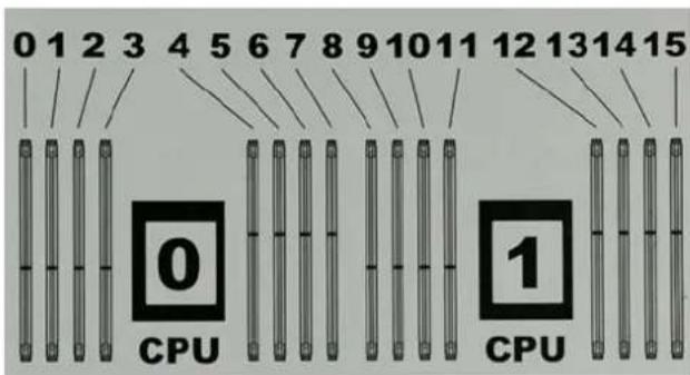
The following figure shows the layout of the CPUs and DIMMs inside the chassis. The front of the system is at the top of the figure.
Figure 7 CPU and memory locations
DIMMs overview
Dual in-line memory modules (DIMM) come in various sizes, which must be configured in a certain way. This topic can help you select the correct configuration when servicing DIMMs.
The storage processor contains two Intel processors each with an integrated memory controller that supports four channels of memory. The storage processor allows two DIMM slots per channel, so the storage processor supports a total of 16 DIMM slots.
DD6300 memory DIMM configuration
Table 21 DD6300 memory DIMM configuration
| Tier Total Memory Memory DIMM Configuration | |
| DD6300 AIO Expanded 96 GB 12 x 8 GB | |
| DD6300 AIO 48 GB 6 x 8 GB |
To ensure maximum memory performance, there are memory DIMM population rules for best memory loading and interleaving. Table 22 on page 30 and Table 23 on page 31 specify the DIMM location rules for various memory configurations:
Table 22 Memory locations - CPU 0
| Channel A Channel | B Channel D Channel | C | |||||||
| Tier Total | Memory | 0 1 2 3 4 5 6 7 | |||||||
| DD6300 AIO Expanded | 96 GB | 8 GB | N/A | 8 GB | N/A | 8 GB | 8 GB | 8 GB | 8 GB |
| DD6300 AIO | 48 GB | N/A | N/A | 8 GB | N/A | N/A | 8 GB | N/A | 8 GB |
Table 23 Memory locations - CPU 1
| Channel A Channel | B Channel D Channel C | ||||||||
| Tier Total | Memory | 8 9 10 11 12 | 13 14 15 | ||||||
| DD6300 AIO Expanded | 96 GB 8 GB 8 | GB 8 GB 8 | GB N/A 8 GB | N/A 8 GB | |||||
| DD6300 AIO | 48 GB | 8 GB | N/A | 8 GB | N/A | N/A | 8 GB | N/A | N/A |
DD6800 system features
Table 24 DD6800 system features
| Feature | DD6800 DLH (Base configuration) | DD6800 DLH (Expanded configuration) | |
| Processor | E5-2630 V3 | E5-2630 V3 | |
| Kernel | 3.2.x | 3.2.x | |
| Memory con-figuration | Non-extended retention | 192 GB | 192 GB |
| DD Cloud Tier N/A | 192 GB | ||
| Extended retention | N/A | 192 GB^a | |
| DIMMs | 8x8 GB + 8x16 GB | 8x8 GB + 8x16 GB | |
| Supported capacity | Non-extended retention (Active tier) | 144 TB | 288 TB |
| DD Cloud Tier N/A | 576 TB | b | |
| Extended retention (Archive tier) | N/A | 288 TB^a | |
| Stream count | 405 writes, 112 reads | 405 writes, 112 reads | |
| HDDs in 3.5" bays | 4 | 4 | |
| SSDs in 3.5" bays | 2 | 4 | |
| SSDs in 2.5" bays | 0 | 0 | |
| NVRAM | NVRAM 8g Model 3 | NVRAM 8g Model 3 | |
| High availability configuration support | Yes | Yes | |
| HA Private Interconnect | (2) 10GBase-T ports | (2) 10GBase-T ports | |
| External SSD shelf | One SSD shelf for A-P high availability cluster containing two drives. | One SSD shelf for A-P high availability cluster containing four drives. | |
| SAS I/O modules (Quad Port 6 Gbps SAS | 2 | 2 | |
| Feature DD6800 DLH (Base | configuration) | DD6800 DLH (Expanded configuration) | |
| SAS string depth (max) | ES30 6 6 (7 for extended retention) | ||
| DS60 3 3 | |||
| ES30 and DS60 5 shelves total 5 shelves total | |||
a. Extended retention not available on HA configurations
b. DD Cloud Tier requires two ES30 shelves fully populated with 4 TB drives to store DD Cloud Tier metadata.
DD6800 system specifications
Table 25 DD6800 system specifications
| Model Average | power consumption 25 C | Heat dissipation (operating maximum) | Weighta | Width Depth | Height | |
| DD6800 560W | 1.69 x 10 | ^6J/hr (1604 Btu/hr) maximum | 68 lbs (30.84 kg) | 17.50 in (44.45 cm) | 30.5 in (77.5 cm) | 3.40 in (8.64 cm) |
a. The weight does not include mounting rails. Allow 2.3-4.5 kg (5-10 lb) for a rail set.
Table 26 System operating environment
| Requirement Description | |
| Ambient temperature 10°C - 35°C; derate 1.1°C per 1,000 ft (304 m) | |
| Relative humidity (extremes) 20–80% noncondensing | |
| Elevation 0 - 7,500ft (0 - 2,268m) | |
| Operating acoustic noise | L_wad sound power, 7.5 Bels |
Internal system components
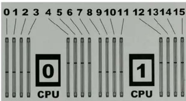
The following figure shows the layout of the CPUs and DIMMs inside the chassis. The front of the system is at the top of the figure.
Figure 8 CPU and memory locations
DIMMs overview
Dual in-line memory modules (DIMM) come in various sizes, which must be configured in a certain way. This topic can help you select the correct configuration when servicing DIMMs.
The storage processor contains two Intel processors each with an integrated memory controller that supports four channels of memory. The storage processor allows two DIMM slots per channel, so the storage processor supports a total of 16 DIMM slots.
DD6800 memory DIMM configuration
Table 27 DD6800 memory DIMM configuration
| Tier Total Memory Memory DIM | IM Configuration | |
| DD6800 DLH 192 GB 8 x 16 GB | +8 x 8 GB | |
| DD6800 DLH Extended Retention/DD Cloud Tier | 192 GB 8 x 16 GB +8 x 8 GB |
HA is supported with all available memory configurations.
To ensure maximum memory performance, there are memory DIMM population rules for best memory loading and interleaving. Table 28 on page 33 and Table 29 on page 34 specify the DIMM location rules for various memory configurations:
Table 28 Memory locations - CPU 0
| Channel A Channel | B Channel D Channel C | ||||||||
| Tier Total | Memory | 0 1 2 3 4 5 | 6 7 | ||||||
| DD6800 DLH | 192 GB | 16 GB | 8 GB | 16 GB | 8 GB | 8 GB | 16 GB | 8 GB | 16 GB |
| DD6800 DLH Extended | 192 GB | 16 GB | 8 GB | 16 GB | 8 GB | 8 GB | 16 GB | 8 GB | 16 GB |
| Retention/D D Cloud Tier | |||||||||
Table 29 Memory locations - CPU 1
| Channel A Channel | B Channel D Channel | C | |||||||
| Tier Total | Memory | 8 9 10 11 12 | 13 14 15 | ||||||
| DD6800 DLH | 192 GB | 16 GB | 8 GB | 16 GB | 8 GB | 8 GB | 16 GB | 8 GB | 16 GB |
| DD6800 DLH Extended Retention/D D Cloud Tier | 192 GB | 16 GB | 8 GB | 16 GB | 8 GB | 8 GB | 16 GB | 8 GB | 16 GB |
DD9300 system features
Table 30 DD9300 system features
| Feature | DD9300 DLH (Base configuration) | DD9300 DLH (Expanded configuration) | |
| Processor | E5-2680 V3 | E5-2680 V3 | |
| Kernel | 3.2.x | 3.2.x | |
| Memory con-figuration | Non-extended retention | 192 GB | 384 GB |
| DD Cloud Tier N/A | 384 GB | ||
| Extended retention | N/A | 384 GB^a | |
| DIMMs | 4x32 GB + 4x16 GB | 8x32 GB + 8x16 GB | |
| Supported capacity | Non-extended retention (Active tier) | 384TB | 720 TB |
| DD Cloud Tier N/A | 1440 TB | b | |
| Extended retention (Archive tier) | N/A | 720 TB^a | |
| Stream count | 810 writes, 225 reads | 810 writes, 225 reads | |
| HDDs in 3.5" bays | 4 | 4 | |
| SSDs in 3.5" bays | 5 | 8 | |
| SSDs in 2.5" bays | 0 | 0 | |
| NVRAM | NVRAM 8g Model 3 | NVRAM 8g Model 3 | |
| High availability configuration support | Yes | Yes | |
| HA Private Interconnect | (2) 10GBase-T ports | (2) 10GBase-T ports | |
| Feature DD9300 DLH (Base configuration) DD9300 DLH (Expanded configuration) | |||
| External SSD shelf One SSD shelf for A-P high availability cluster containing five drives. | One SSD shelf for A-P high availability cluster containing eight drives. | ||
| SAS I/O modules (Quad Port 6 Gbps SAS | 2 | 2 | |
| SAS string depth (max) | ES30 6 6 (7 for extended retention) | ||
| DS60 3 3 | |||
| ES30 and DS60 5 shelves total 5 shelves total | |||
a. Extended retention not available on HA configurations
b. DD Cloud Tier requires four ES30 shelves fully populated with 4 TB drives to store DD Cloud Tier metadata.
DD9300 system specifications
Table 31 DD9300 system specifications
| Model Average | power consumption 25 C | Heat dissipation (operating maximum) | Weighta | Width Depth | Height | |
| DD9300 645W 1 | 69 x 10 | ^6J/hr (1604 Btu/hr) maximum | 70 lbs (31.75 kg) | 17.50 in (44.45 cm) | 30.5 in (77.5 cm) | 3.40 in (8.64 cm) |
a. The weight does not include mounting rails. Allow 2.3-4.5 kg (5-10 lb) for a rail set.
Table 32 System operating environment
| Requirement Description | |
| Ambient temperature 10°C - 35°C; derate 1.1°C | per 1,000 ft (304 m) |
| Relative humidity (extremes) | 20–80% noncondensing |
| Elevation | 0 - 7,500ft (0 - 2,268m) |
| Operating acoustic noise | L_wad sound power, 7.5 Bels |
Internal system components
The following figure shows the layout of the CPUs and DIMMs inside the chassis. The front of the system is at the top of the figure.
Figure 9 CPU and memory locations
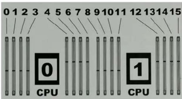
DIMMs overview
Dual in-line memory modules (DIMM) come in various sizes, which must be configured in a certain way. This topic can help you select the correct configuration when servicing DIMMs.
The storage processor contains two Intel processors each with an integrated memory controller that supports four channels of memory. The storage processor allows two DIMM slots per channel, so the storage processor supports a total of 16 DIMM slots.
DD9300 memory DIMM configuration
Table 33 DD9300 memory DIMM configuration
| Tier Total Memory Memory DIM | IM Configuration | |
| DD9300 DLH Expanded 384 GB | 8 x 32 GB + 8 x 16 GB | |
| DD9300 DLH 192 GB 4 x 32 GB | + 4 x 16 GB | |
| DD9300 DLH Extended Retention/DD Cloud Tier | 384 GB 8 x 32 GB +8 x 16 GB |
HA is supported with all available memory configurations.
To ensure maximum memory performance, there are memory DIMM population rules for best memory loading and interleaving. Table 34 on page 36 and Table 35 on page 37 specify the DIMM location rules for various memory configurations:
Table 34 Memory locations - CPU 0
| Channel A Channel | B Channel D Channel C | ||||||||
| Tier Total | Memory | 0 1 2 3 4 5 6 7 | |||||||
| DD9300 DLH Expanded | 384 GB | 32 GB | 16 GB | 32 GB | 16 GB | 16 GB | 32 GB | 16 GB | 32 GB |
| DD9300 DLH 19 | 2 GB 16 GB N/A | 16 GB N/A | N/A 32 GB | N/A 32 GB | |||||
| DD9300 DLH Extended Retention/DD Cloud Tier | 384 GB 32 GB | 16 GB 32 GB | 16 GB 16 GB | 32 GB 16 GB | 32 GB | ||||
Table 35 Memory locations - CPU 1
| Channel A Channel | B Channel D Channel C | ||||||||
| Tier Total | Memory | 8 | 9 | 10 | 11 | 12 | 13 | 14 | 15 |
| DD9300 DLH Expanded | 384 GB | 32 GB | 16 GB | 32 GB | 16 GB | 16 GB | 32 GB | 16 GB | 32 GB |
| DD9300 DLH | 192 GB | 32 GB | N/A | 32 GB | N/A | N/A | 16 GB | N/A | 16 GB |
| DD9300 DLH Extended Retention/DD Cloud Tier | 384 GB | 32 GB | 16 GB | 32 GB | 16 GB | 16 GB | 32 GB | 16 GB | 32 GB |
Data Domain DD6300, DD6800, and DD9300 Hardware Overview
CHAPTER 3
Install the System in the Rack
- Unpack the system.... 40
- Rails and cable management assembly....40
- Identify the rack location to install the system....41
• Install the rails....41
• Install the DD6300, DD6800, or DD9300 system into a rack.... 43
• Installing the cable management assembly (CMA)...... 45
• Installing the expansion shelves into the racks....46
Unpack the system
- Remove the accessories and rail mount kit from the shipping packages.
- Remove the controller and the bezels from the shipping packages.
Data Domain systems are heavy. Always use two people or a mechanical lift to move a system.
Figure 10 Warning about lifting the system

- Remove expansion shelves and their bezels from the shipping packages.
Rails and cable management assembly
The rail kit is universal in that it supports all rack mounting hole types and sizes. Both the front and the rear ends of the rail kit contain threaded posts that come with a cap installed. The cap fits square and round hole unthreaded racks. Large flat headed M4 screws insert through the rail into the rail kit to secure the rail to the rack.
When installing rails, do not tighten the screws all the way until all the screws are in place. This assures that the screws are all screwed in the same distance, and prevents one from skewing the others.
The rail kit includes two bracket assemblies, one marked for the left side and one marked for the right side of the rack.
A cable management assembly (CMA), for organization of cables at the rear of the system, is already installed onto the system on a Data Domain rack. For field installed systems, the CMA is shipped with the system.
Figure 11 Cable management assembly (CMA)
natural_image
Technical line drawing of a server rack unit with multiple ports and connectors (no text or labels)Identify the rack location to install the system
Identify the designated location for the system controller or controllers in the rack.
- When using DD6300, DD6800, and DD9300 systems with ES30 shelves:
- The designated location for a single node, or the primary node of an HA pair is U13-U14 in rack 1.
■ The designated location for the standby node of an HA pair is U15-16 in rack 1. - When using DD6300, DD6800, and DD9300 systems with DS60 shelves:
■ The designated location for a single node, or the primary node of an HA pair is U22-U23 in rack 1.
■ The designated location for the standby node of an HA pair is U25-26 in rack 1.
Note
The designated slots in the rack are the recommended location for the DD6300, DD6800, and DD9300 systems to support the cabling described in this document. Other locations may require different cable lengths for some configurations.
Install the rails
This procedures describes how to install the mounting rails.
Procedure
- If EIA rail mounting holes of 7.1 MM diameter round, or M5, 12-24, 10-32 threaded, are being used, install the filler using the pin as shown. If not, proceed to the next step.
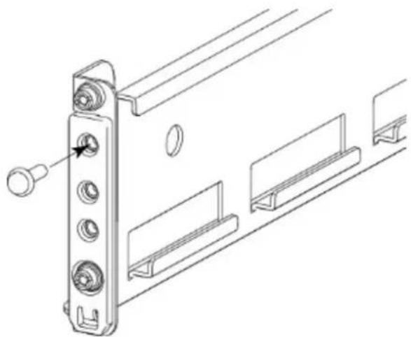
natural_image
Technical line drawing of a mechanical bracket assembly with mounting holes and mounting brackets (no text or symbols)Once the filler is installed to the rail, the installation can continue as follows.
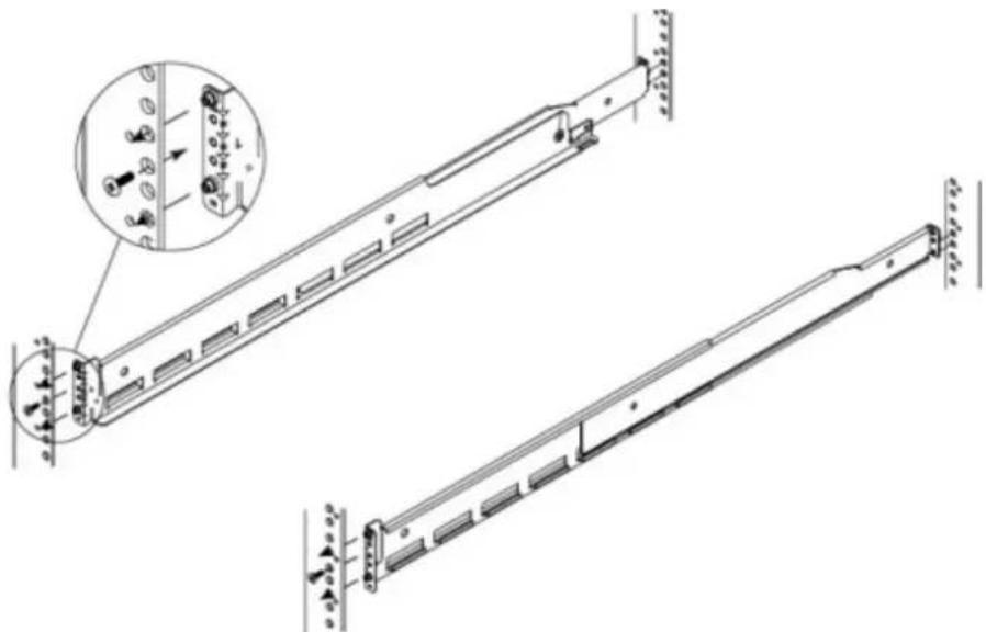
- At the front of the cabinet, insert the two adaptors on the front of the rail into the correct holes in the 2U space.
natural_image
Technical line drawing of a mechanical assembly with two views (top and side), showing structural components and mounting brackets (no text or symbols)- Insert one screw into the lower hole to hold the front of the rails in place. Do not fully tighten the screw at this time.
Note
An 18-inch screwdriver (minimum) is required to install the screw into the rear of the rails.
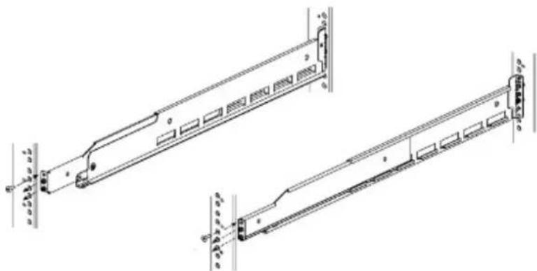
- At the rear of the cabinet, align and insert the two adaptors on the rear of the rail with the mounting holes in the NEMA channel. Make sure the rail is level.
natural_image
Technical line drawing of a server rack with mounting brackets and connectors (no text or symbols)- Use an 18-inch screwdriver (minimum) to secure the rear of the rail to the NEMA channel using one screw.
- Tighten the front screw.
- Repeat for the other rail.
Install the DD6300, DD6800, or DD9300 system into a rack
CAUTION
Data Domain systems are heavy. Always use two people or a mechanical lift to move a system.
Figure 12 Warning about lifting the system

CAUTION
- The system controller should be installed in the pre-defined location for the system controller in the rack to comply with Data Domain rack mounting guidelines.
- Do not apply AC power to the system controller until all expansion shelves and cables are installed.
- Ensure the PSNT label, which is in a slot just beneath the power supply on the rear of the chassis is not damaged or snagged during the installation of the system into the rack.
Procedure
-
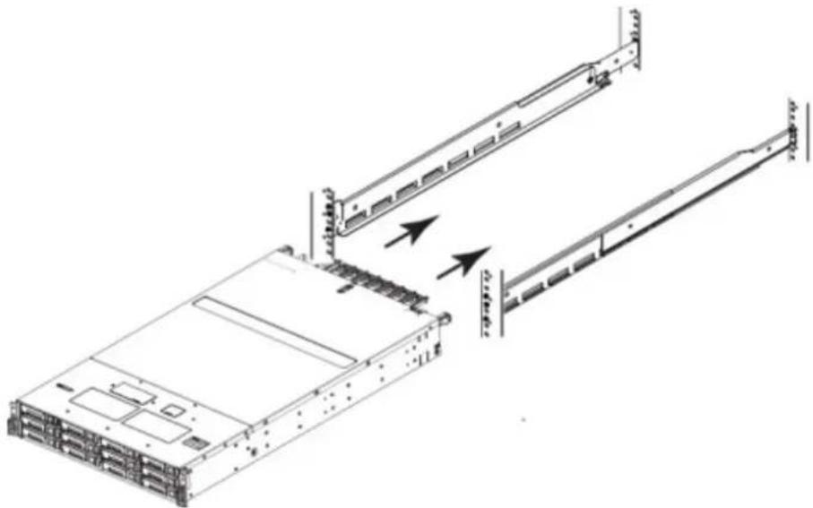
From the front of the rack, lift the chassis to install the system in the rack in the correct location.
-
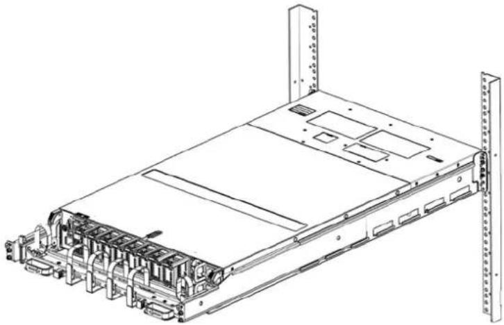
Slide the unit onto the rails and push it fully into the cabinet until the mounting holes on the unit are flush with the NEMA channel.
natural_image
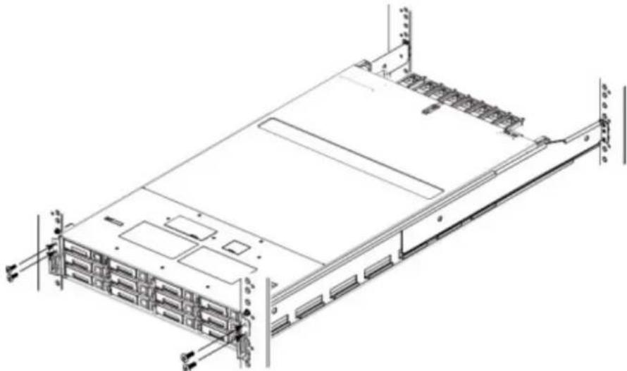
Technical line drawing of a server rack with two cable extensions, showing internal structure and mounting points (no text or symbols)- Secure the unit to the NEMA channel and rails using four screws, two on each side.
natural_image
Technical line drawing of a server rack unit with multiple drive bays and mounting brackets (no text or labels)- Check the PSNT label in the slot just beneath the power supply at the rear of the chassis.
Figure 13 Service tag (components removed for clarity)
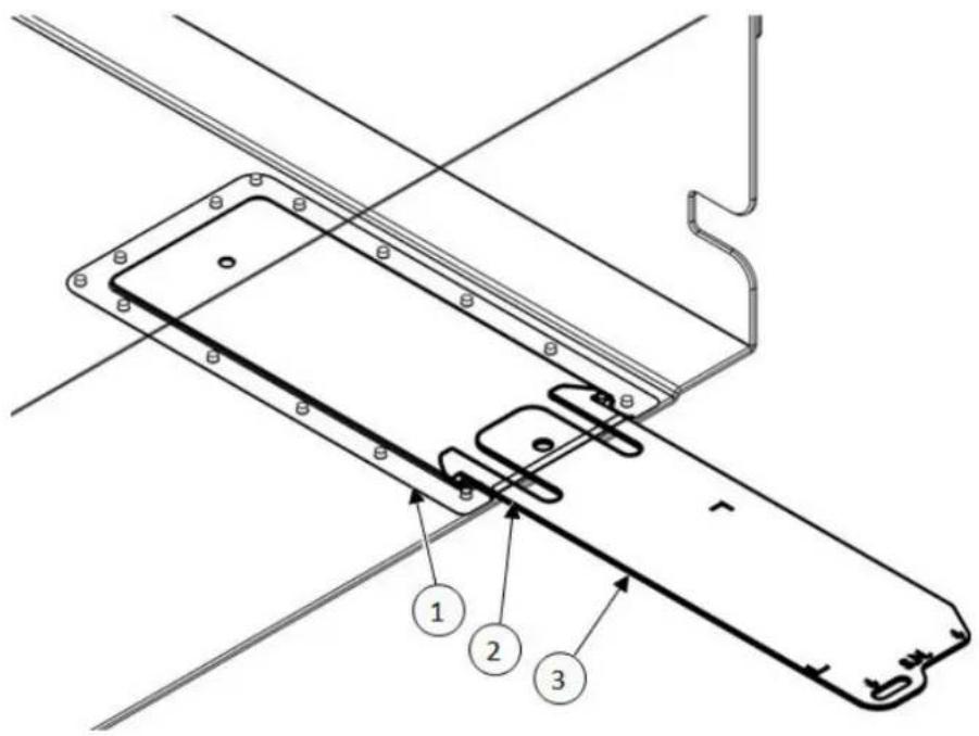
- Service tag bracket
- Locking tab
- Service tag
Installing the cable management assembly (CMA)
Installing a cable management assembly (CMA) can help keep the system neat and organized.
Procedure
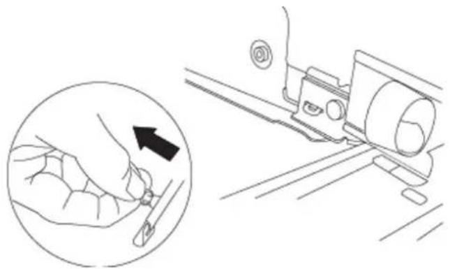
- Align and insert the CMA tabs in the tongues on the rails and align the plunger in the hole of the mounting rail on both sides.
- Working one side at a time, pull out the plunger and slide the CMA tabs as required until the plunger pin snaps into the mounting hole of the rail.
Figure 14 Installing the CMA on the rack
natural_image
Line drawing showing a hand holding a tool near a vehicle, with an inset magnified view of the tool's tip (no text or symbols)-
Open the velcro straps to route cables through the CMA. Secure the cables in place using the velcro straps.
-
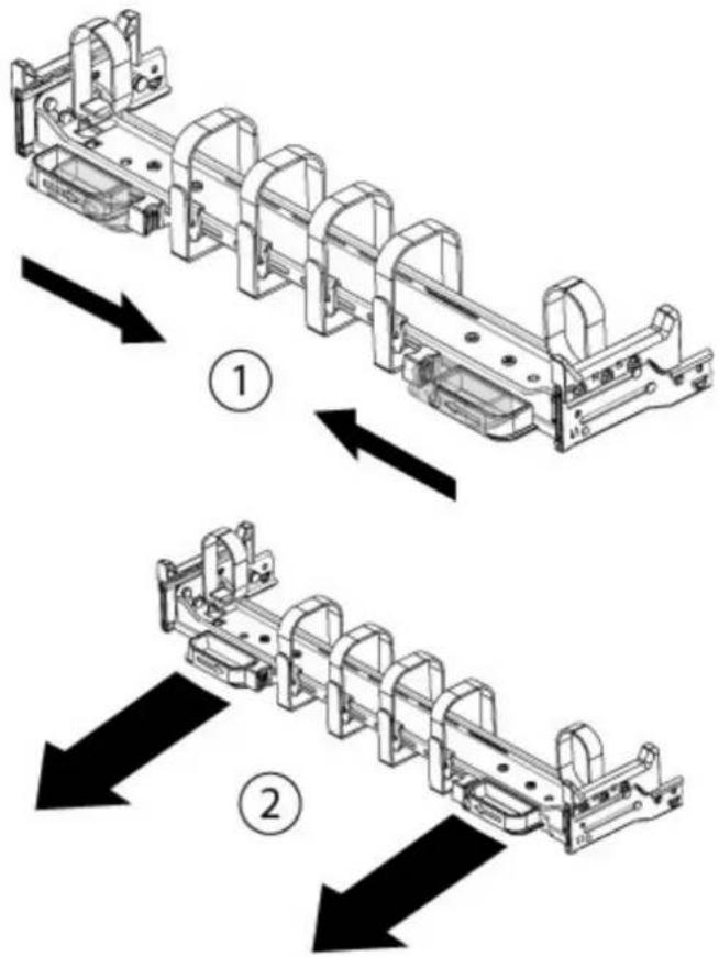
To adjust the CMA position depth (in or out), pull inward on the orange latches (1) and pull out or push in on the arm simultaneously as needed (2).
Note
The I/O modules, the NVRAM module, the power supply units and the 2.5" disks can be accessed for removal and replacement with the CMA in place. Adjust the depth of the CMA arms to access these modules.
Figure 15 Adjusting the CMA depth
Installing the expansion shelves into the racks
CAUTION
- Data Domain systems are heavy. Always use two people or a mechanical lift to move and install a Data Domain system. Use caution to install the expansion shelves.
-
Ensure that each rack is securely anchored to prevent tipping.
-
Add shelves to the racks in order, one at a time, from the bottom of a rack to the top filling each string in that rack before going to the next.
Note
Strings in add-on racks may connect to the same string number in other racks.
Shelves are added in the order V1.1, V1.2, V1.3, V1.4, V2.1, V2.2, and so on. Shelves are labeled VN.M. VN refers to string "N" and the "M" is the number of the shelf in the string. For example, V3.2 refers to the second shelf in the third string.
-
Secure each expansion shelf in the rack.
-
When installing an SSD shelf for Data Domain metadata on flash:
-
The SSD shelf counts towards the total number of shelves connected to the system.
- Data Domain recommends installing the SSD shelf in the V1.1 positon, but if that is not possible, the shelf can be placed in a different location in the rack so long as cables of sufficient length are available.
Note
V1.1 is recommended for better performance because this will the 1^st hop where data will be written. If the SSD shelf is connected to the last enclosure in a chain, then each read/write request has to go through many hops, which introduces latency issues when compared to when the SSD shelf is on the 1^st shelf of a chain.
Install the System in the Rack
CHAPTER 4
Connect Cables and Power on
- Connecting ES30 shelves....50
- Connecting DS60 shelves.... 57
- Connecting the HA interconnect....69
• Installing the front bezel....70 - Connect data cables....70
• Power on all systems....71
Connecting ES30 shelves
The cabling diagrams in this section show the maximum configurations for the DD6300, DD6800, and DD9300 systems. Not all systems will have all the disk shelves shown in the diagrams.
Add shelf-to-shelf cables between shelves in a loop and to the controller as shown in the diagrams.
-
Cable from the B Controller EXPANSION port of the lower shelf to the B controller HOST port of the next higher shelf.
-
Then cable from the A Controller HOST port of lower shelf to the A controller EXPANSION port of the next higher shelf
-
There are no specific placement or cabling requirements for SSD shelves, or the metadata shelves for DD Cloud Tier configurations. These shelves can be installed and cabled the same way as standard ES30 shelves. SSD shelves and DD Cloud Tier metadata do not need to be cabled in a separate set from the other ES30 shelves.
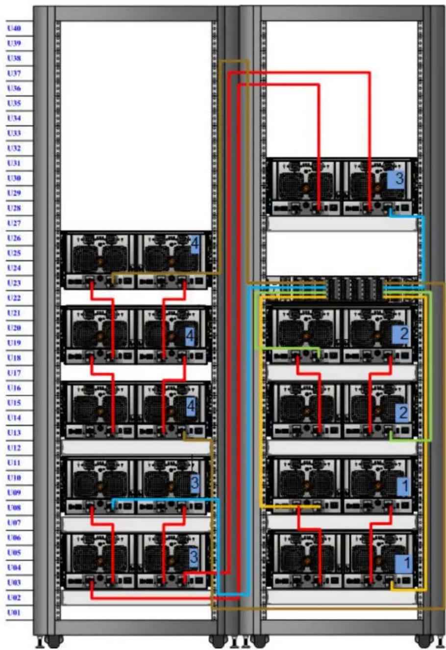
For HA pairs, the primary and standby nodes use different cables to connect to ES30 shelves. The primary node uses cables for ES30 host ports ( ) and the standby node uses cables for ES30 expansion ports ( ).
ES30 cable information
When connecting ES30 shelves, different cables are required for the following connections:
- Connecting the primary node to the ES30 shelf loop
- Connecting the standby node to the ES30 shelf loop
- Connecting an ES30 shelf to an ES30 shelf within a loop
Table 36 Cables for primary node to ES30 shelf loop
| HD-mini-SAS connector on controller, SFF-8088 connector keyed for host port on ES30 | ||
| Cable model code Part num | ber Cable length | |
| X-SAS-HDMS2 038-003-810 2 | m (79 in) | |
| X-SAS-HDMS3 038-003-811 3 | m (118 in) | |
| X-SAS-HDMS5 038-003-813 5 | m (196 in) | |
Table 37 Cables for standby node to ES30 shelf loop
| HD-mini-SAS connector on controller, SFF-8088 connector keyed for expansion port on ES30 | ||
| Cable model Part number | Cable length | |
| X-HA-ES30-SAS-2 038-004-10 | 8 2 m (79 in) | |
| X-HA-ES30-SAS-5 038-004-11 | 5 m (196 in) | |
Table 38 ES30 to ES30 cable options
| Mini-SAS cable, SFF-8088 connectors on both ends, one end keyed for host ports and the other keyed for expansion ports | ||
| Cable model Part number Cable | length | |
| X-SAS-MSMS1 038-003-786 1 m (39 in.) | ||
| X-SAS-MSMS2 038-003-787 2 m (79 in.) | ||
| X-SAS-MSMS3 038-003-751 3 m (118 in.) | ||
| X-SAS-MSMS4 038-003-628 4 m (158 in.) | ||
| X-SAS-MSMS5 038-003-666 5 m (196 in.) | ||
Select the appropriate configuration from the following list, and connect the disk shelves to the Data Domain controller.
• DD6300 on page 51
• DD6800 and DD9300 (single node, DD Cloud Tier, or ERSO) on page 52
• DD6800 and DD9300 (HA or HA with DD Cloud Tier) on page 54
DD6300
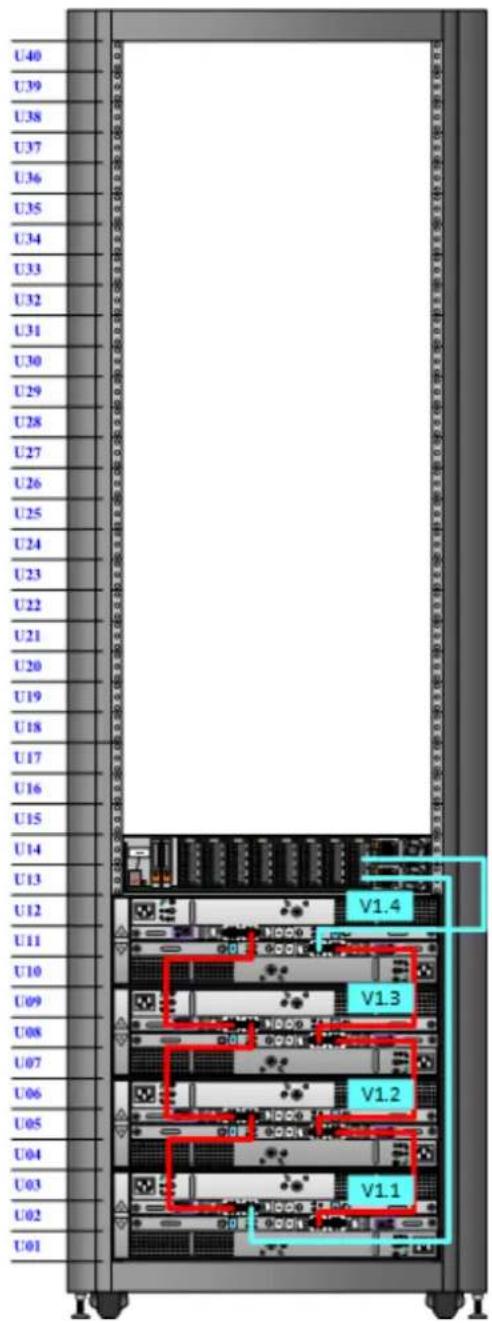
The DD6300 system supports a maximum of four shelves, cabled in a single set.
| String (Loop) | I/O - Port Shelf | Port Length | a |
| 1 I/O 7 - Port 0 | B controller HOST port of shelf V1.1 | 2M | |
| 1 I/O 7 - Port 2 | A controller HOST port of the highest number shelf in V1 | 2M | |
a. Cable lengths shown are designed for Data Domain racks. Longer cables (up to 5M) can be used.
Figure 16 DD6300 with ES30 shelves
DD6800 and DD9300 (single node, DD Cloud Tier, or ERSO)
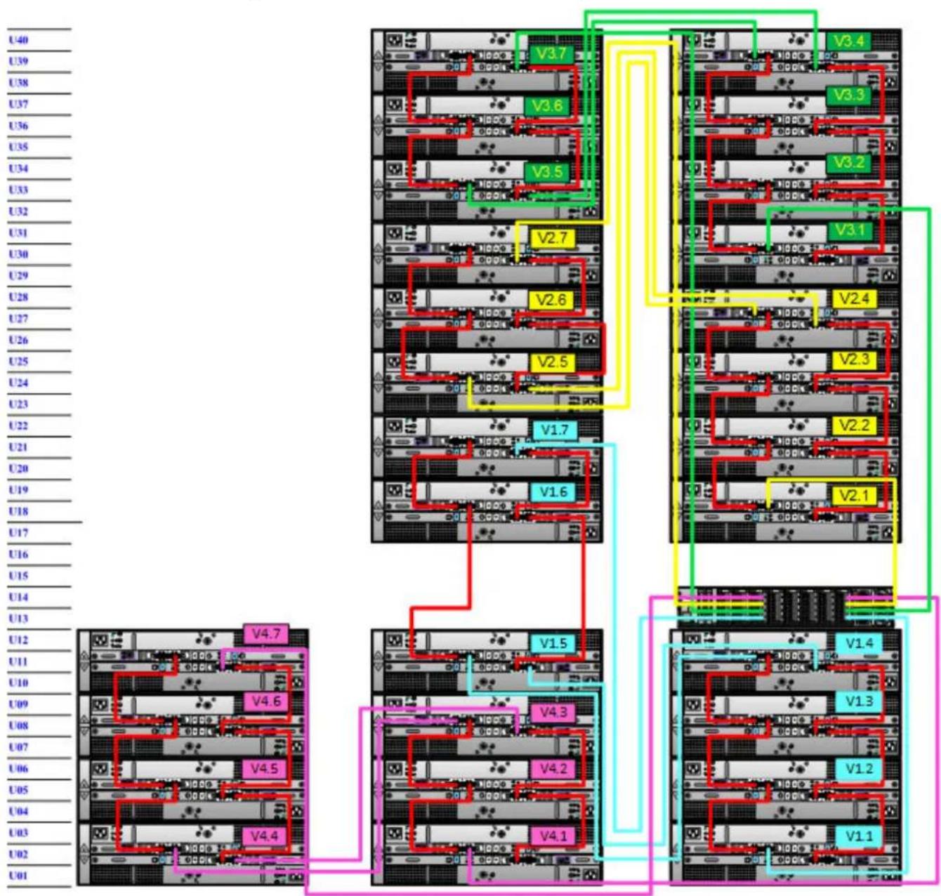
The DD6800 and DD9300 systems support a maximum of 28 shelves, divided into four sets of seven shelves.
Note
For configurations of 16 SAS shelves or less, do not exceed four shelves per set.
| String (Loop) | I/O - Port Shelf | Port Length | a |
| 1 I/O 7 - Port 0 | B controller HOST port of shelf V1.1 | 2M | |
| 1 I/O 2 - Port 0 | A controller HOST port of the highest number shelf in V1 | 2M | |
| 2 I/O 7 - Port 2 | B controller HOST port of shelf V2.1 | 2M | |
| 2 I/O 2 - Port 2 | A controller HOST port of the highest number shelf in V2 | 2M | |
| 3 I/O 7 - Port 1 | B controller HOST port of shelf V3.1 | 2M | |
| 3 I/O 2 - Port 1 | A controller HOST port of the highest number shelf in V3 | 2M | |
| 4 I/O 7 - Port 3 | B controller HOST port of shelf V4.1 | 3M | |
| 4 I/O 2 - Port 3 | A controller HOST port of the highest number shelf in V4 | 3M | |
a. Cable lengths shown are designed for Data Domain racks. Longer cables (up to 5M) can be used.
Figure 17 DD6800 and DD9300 with ES30s, single node, DD Cloud Tier, or ER
DD6800 and DD9300 (HA or HA with DD Cloud Tier)
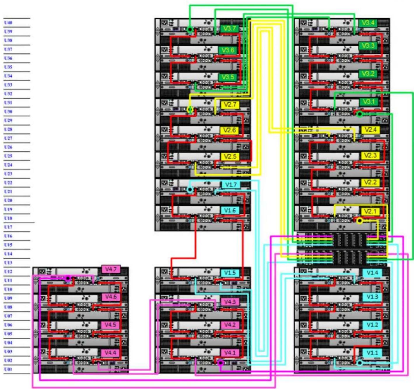
The DD6800 and DD9300 systems support a maximum of 28 shelves, divided into four sets of seven shelves.
Note
For configurations of 16 SAS shelves or less, do not exceed four shelves per set.
Table 39 Primary node cabling instructions
| String (Loop) | I/O - Port Shelf | Port Length | a |
| 1 I/O 7 - Port 0 | B controller HOST port of shelf V1.1 | 2M | |
| 1 I/O 2 - Port 0 | A controller HOST port of the highest number shelf in V1 | 2M | |
| 2 I/O 7 - Port 2 | B controller HOST port of shelf V2.1 | 2M | |
| 2 I/O 2 - Port 2 | A controller HOST port of the highest number shelf in V2 | 2M | |
| 3 I/O 7 - Port 1 | B controller HOST port of shelf V3.1 | 2M | |
| 3 I/O 2 - Port 1 | A controller HOST port of the highest number shelf in V3 | 2M | |
| 4 I/O 7 - Port 3 | B controller HOST port of shelf V4.1 | 3M | |
| 4 I/O 2 - Port 3 | A controller HOST port of the highest number shelf in V4 | 3M | |
a. Cable lengths shown are designed for Data Domain racks. Longer cables (up to 5M) can be used.
Table 40 Standby node cabling instructions
| String (Loop) | I/O - Port Shelf | Port Length | a |
| 1 I/O 7 - Port 0 | A controller EXPANSION port of shelf V1.1 | 2M | |
| 1 I/O 2 - Port 0 | B controller EXPANSION port of the highest number shelf in V1 | 2M | |
| 2 I/O 7 - Port 2 | A controller EXPANSION port of shelf V2.1 | 2M | |
| 2 I/O 2 - Port 2 | B controller EXPANSION port of the highest number shelf in V2 | 2M | |
| 3 I/O 7 - Port 1 | A controller EXPANSION port of shelf V3.1 | 2M | |
| 3 I/O 2 - Port 1 | B controller EXPANSION port of the highest number shelf in V3 | 2M | |
| 4 I/O 7 - Port 3 | A controller EXPANSION port of shelf V4.1 | 3M | |
| 4 I/O 2 - Port 3 | B controller EXPANSION port of the highest number shelf in V4 | 3M | |
a. Cable lengths shown are designed for Data Domain racks. Longer cables (up to 5M) can be used.
Figure 18 DD6800 and DD9300 with ES30s and HA or HA with DD Cloud Tier
flowchart
graph TD
    subgraph Server Architecture
        U01["U01"] --> V4.4["V4.4"]
        U02["U02"] --> V4.5["V4.5"]
        U03["U03"] --> V4.6["V4.6"]
        U04["U04"] --> V4.7["V4.7"]
    end

    subgraph Server Architecture
        V4.1["V4.1"] --> V4.2["V4.2"]
        V4.3["V4.3"] --> V4.4["V4.4"]
        V4.5["V4.5"] --> V4.6["V4.6"]
        V4.7["V4.7"] --> V3.1["V3.1"]
        V4.8["V3.1"] --> V2.1["V2.1"]
        V2.2["V2.2"] --> V2.3["V2.3"]
        V2.3["V2.3"] --> V2.4["V2.4"]
        V2.5["V2.5"] --> V2.6["V2.6"]
        V2.7["V2.7"] --> V3.2["V3.2"]
        V3.2["V3.2"] --> V3.3["V3.3"]
        V3.3["V3.3"] --> V3.4["V3.4"]
    end

    subgraph Server Architecture
        V1.1["V1.1"] --> V1.2["V1.2"]
        V1.3["V1.3"] --> V1.4["V1.4"]
        V1.4["V1.4"] --> V1.5["V1.5"]
        V1.5["V1.5"] --> V1.6["V1.6"]
        V1.6["V1.6"] --> V1.7["V1.7"]
    end

    subgraph Server Architecture
        V2.1["V2.1"] --> V2.2["V2.2"]
        V2.3["V2.3"] --> V2.4["V2.4"]
        V2.5["V2.5"] --> V2.6["V2.6"]
        V2.6["V2.6"] --> V2.7["V2.7"]
    end

    subgraph Server Architecture
        V3.1["V3.1"] --> V3.2["V3.2"]
        V3.3["V3.3"] --> V3.4["V3.4"]
        V3.5["V3.5"] --> V3.6["V3.6"]
        V3.7["V3.7"] --> V3.8["V3.8"]
    end

    subgraph Server Architecture
        W1["Power Supply Line"] --> W2["Line Style"]
    end
The cabling diagrams in this section show the maximum configurations for the DD6300, DD6800, and DD9300 systems. Not all systems will have all the disk shelves shown in the diagrams.
Add shelf-to-shelf cables between shelves in a loop and to the controller as shown in the diagrams.
- The recommended cabling for HA utilizes a maximum of three loops.
- There are no specific placement or cabling requirements for SSD shelves. These shelves can be installed and cabled the same way as standard ES30 shelves.
- The SSD shelf counts towards the total number of shelves connected to the system.
- Data Domain recommends installing the SSD shelf in the V1.1 positon, but if that is not possible, the shelf can be placed in a different location in the rack so long as cables of sufficient length are available.
Note
V1.1 is recommended for better performance because this will the 1^st hop where data will be written. If the SSD shelf is connected to the last enclosure in a chain, then each read/write request has to go through many hops, which introduces latency issues when compared to when the SSD shelf is on the 1^st shelf of a chain.
- Use the cable management assembly to support and organize all cables.
Select the appropriate configuration from the following list, and connect the disk shelves to the Data Domain controller.
• DD6300 on page 58
• DD6800 and DD9300 on page 59
• DD6800 and DD9300 with HA on page 61
• DD6800 with DD Cloud Tier on page 62
• DD6800 and with HA and DD Cloud Tier on page 64
• DD9300 with DD Cloud Tier or HA and DD Cloud Tier on page 65
• DD6800 and DD9300 with ERSO on page 67
DD6300
| String (Loop) | I/O - Port Shelf | Port Length | a |
| 1 I/O 7 - | Port 0 A controller | port 0 of the DS60. 2M | |
| 1 I/O 7 - | Port 1 B controller | port 0 of the DS60. 2M |
a. Cable lengths shown are designed for Data Domain racks. Longer cables (up to 5M) can be used.
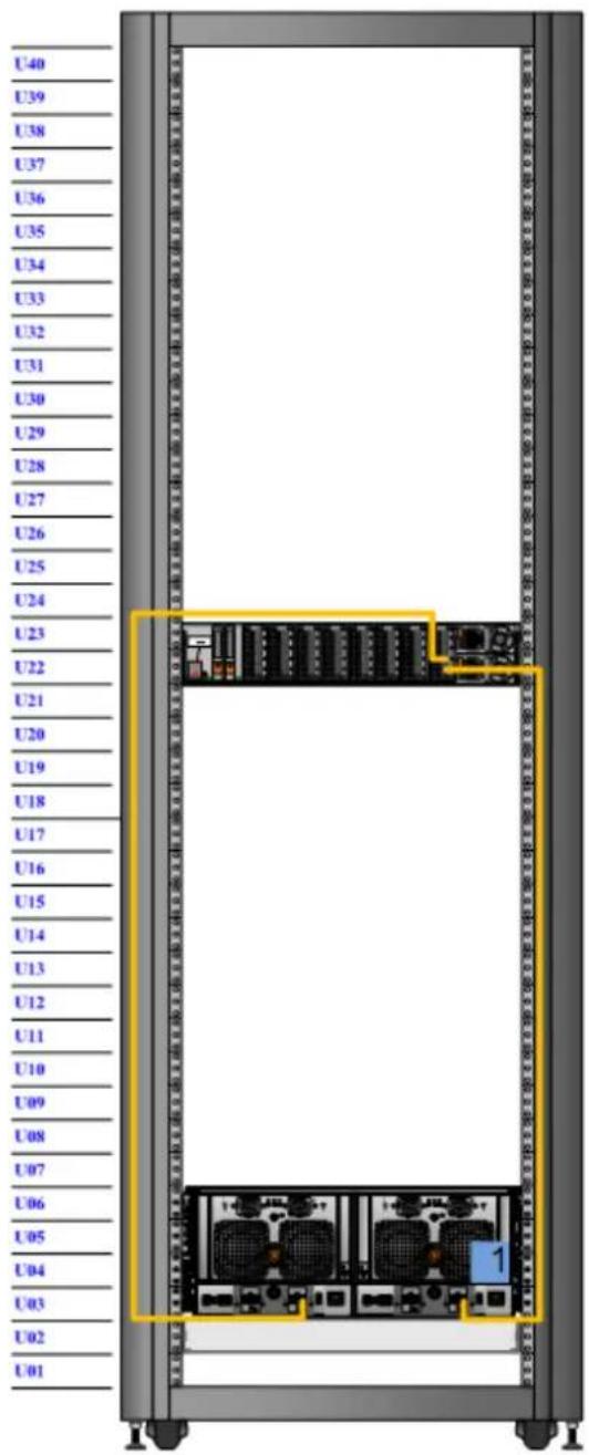
DD6800 and DD9300
| String (Loop) | I/O - Port Shelf | Port Length | a |
| 1 I/O 7 - | Port 0 A controller | port 0 of shelf V1.1 2M | |
| 1 I/O 2 - | Port 0 B controller | port 0 of the highest number shelf in V1 2M | |
| 2 I/O 7 - | Port 1 A controller | port 0 of shelf V2.1 2M | |
| 2 I/O 2 - | Port 1 B controller | port 0 of the highest number shelf in V2 2M | |
| 3 I/O 7 - | Port 2 A controller | port 0 of shelf V3.1 2M | |
| 3 I/O 2 - | Port 2 B controller | port 0 of the highest number shelf in V3 2M |
a. Cable lengths shown are designed for Data Domain racks. Longer cables (up to 5M) can be used.
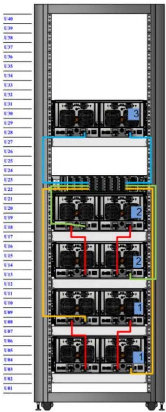
DD6800 and DD9300 with HA
DD6800 and DD9300 with HA
Table 42 Primary node cabling instructions
| String (Loop) | I/O - Port Shelf | Port Length | a |
| 1 I/O 7 - | Port 0 A controller | port 0 of shelf V1.1 2M | |
| 1 I/O 2 - | Port 0 B controller | port 0 of the highest number shelf in V1 2M | |
| 2 I/O 7 - | Port 1 A controller | port 0 of shelf V2.1 2M | |
| 2 I/O 2 - | Port 1 B controller | port 0 of the highest number shelf in V2 2M | |
| 3 I/O 7 - | Port 2 A controller | port 0 of shelf V3.1 2M | |
| 3 I/O 2 - | Port 2 B controller | port 0 of the highest number shelf in V3 2M | |
| 4 I/O 7 - | Port 3 | A controller HOST port of the SSD shelf | 2M |
| 4 I/O 2 - | Port 3 | B controller HOST port of the SSD shelf | 2M |
a. Cable lengths shown are designed for Data Domain racks. Longer cables (up to 5M) can be used.
Table 43 Standby node cabling instructions
| String (Loop) | I/O - Port Shelf | Port Length | a |
| 1 I/O 7 - | Port 0 B controller | port 2 of shelf V1.1 2M | |
| 1 I/O 2 - | Port 0 A controller | port 2 of the highest number shelf in V1 2M | |
| 2 I/O 7 - | Port 1 B controller | port 2 of shelf V2.1 2M | |
| 2 I/O 2 - | Port 1 A controller | port 2 of the highest number shelf in V2 2M | |
| 3 I/O 7 - | Port 2 B controller | port 2 of shelf V3.1 2M | |
| 3 I/O 2 - | Port 2 A controller | port 2 of the highest number shelf in V3 2M | |
| 4 I/O 7 - | Port 3 | A controller EXPANSION ◆ port of the SSD shelf | 2M |
| 4 I/O 2 - | Port 3 | B controller EXPANSION ◆ port of the SSD shelf | 2M |
a. Cable lengths shown are designed for Data Domain racks. Longer cables (up to 5M) can be used.
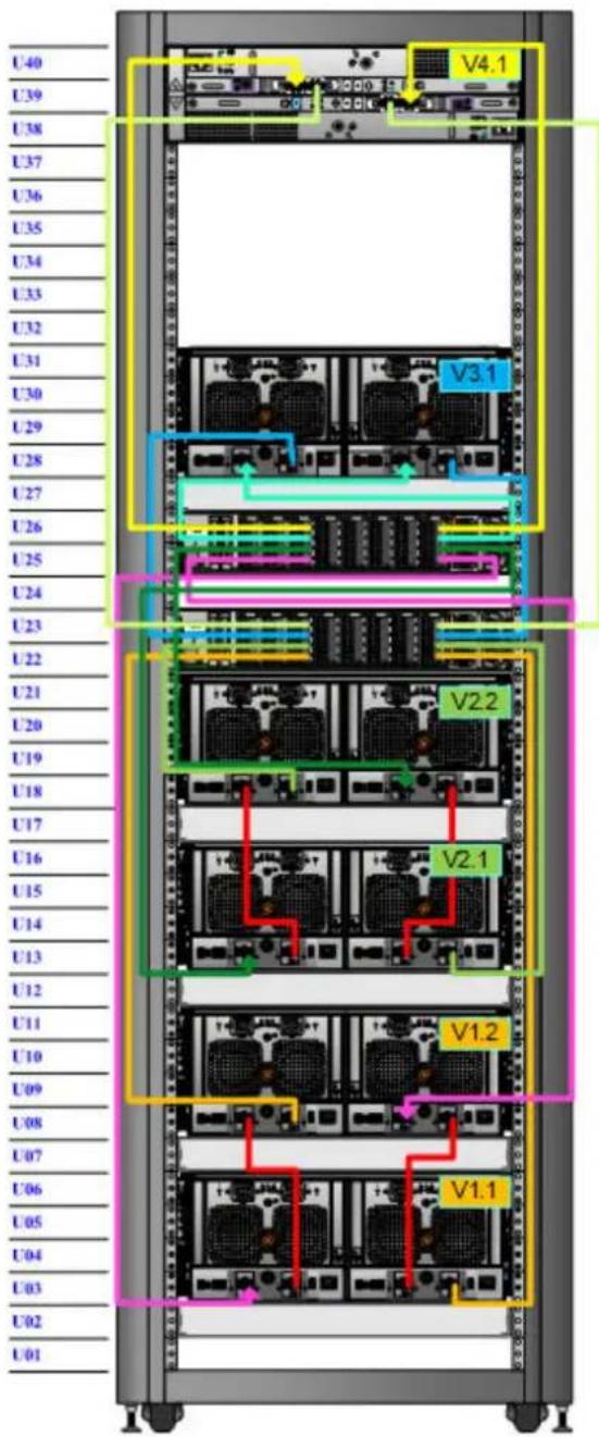
DD6800 with DD Cloud Tier
| String (Loop) | I/O - Port Shelf | Port Length | a |
| 1 I/O 7 - | Port 0 A controller | port 0 of shelf V1.1 2M | |
| 1 I/O 2 - | Port 0 B controller | port 0 of the highest number shelf in V1 2M | |
| 2 I/O 7 - | Port 1 | A controller HOST port of the second metadata shelf | 2M |
| 2 I/O 2 - | Port 1 | B controller HOST port of the first metadata shelf | 2M |
a. Cable lengths shown are designed for Data Domain racks. Longer cables (up to 5M) can be used.
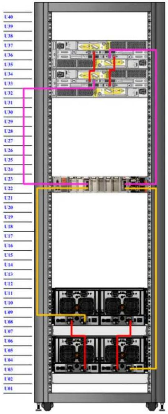
DD6800 and with HA and DD Cloud Tier
Table 44 Primary node cabling instructions
| String (Loop) | I/O - Port Shelf | Port Length | a |
| 1 I/O 7 - | Port 0 A controller | port 0 of shelf V1.1 2M | |
| 1 I/O 2 - | Port 0 B controller | port 0 of the highest number shelf in V1 2M | |
| 2 I/O 7 - | Port 2 | A controller HOST port of the second metadata shelf | 2M |
| 2 I/O 2 - | Port 2 | B controller HOST port of the first metadata shelf | 2M |
| 3 I/O 7 - | Port 3 | A controller HOST port of the SSD shelf | 2M |
| 3 I/O 2 - | Port 3 | B controller HOST port of the SSD shelf | 2M |
a. Cable lengths shown are designed for Data Domain racks. Longer cables (up to 5M) can be used.
Table 45 Standby node cabling instructions
| String (Loop) | I/O - Port Shelf | Port Length | a |
| 1 I/O 7 - | Port 0 B controller | port 2 of shelf V1.1 2M | |
| 1 I/O 2 - | Port 0 A controller | port 2 of the highest number shelf in V1 2M | |
| 2 I/O 7 - | Port 2 | B controller EXPANSION port of the second metadata shelf | 2M |
| 2 I/O 2 - | Port 2 | A controller EXPANSION port of the first metadata shelf | 2M |
| 3 I/O 7 - | Port 3 | A controller EXPANSION port of the SSD shelf | 2M |
| 3 I/O 2 - | Port 3 | B controller EXPANSION port of the SSD shelf | 2M |
a. Cable lengths shown are designed for Data Domain racks. Longer cables (up to 5M) can be used.
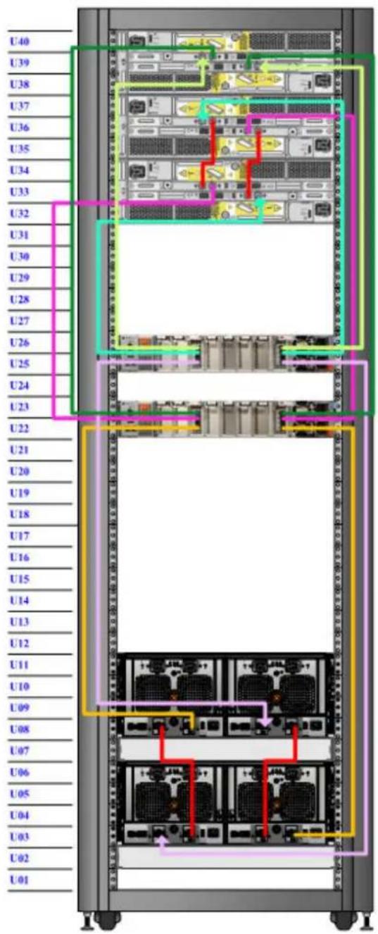
DD9300 with DD Cloud Tier or HA and DD Cloud Tier
Table 46 Primary node cabling instructions
| String (Loop) | I/O - Port Shelf | Port Length | a |
| 1 I/O 7 - | Port 0 A controller | port 0 of shelf V1.1 2M | |
| 1 I/O 2 - | Port 0 B controller | port 0 of the highest number shelf in V1 2M | |
| 2 I/O 7 - | Port 1 A controller | port 0 of shelf V2.1 2M | |
| 2 I/O 2 - | Port 1 B controller | port 0 of the highest number shelf in V2 2M | |
| 3 I/O 7 - | Port 2 A controller | port 0 of shelf V3.1 2M | |
| 3 I/O 2 - | Port 2 B controller | port 0 of the highest number shelf in V3 5M | |
| 4 I/O 7 - | Port 3 | A controller HOST port of the SSD shelf | 2M |
| 4 I/O 2 - | Port 3 | B controller HOST port of the SSD shelf | 2M |
a. Cable lengths shown are designed for Data Domain racks. Longer cables (up to 5M) can be used.
Table 47 Standby node cabling instructions
| String (Loop) | I/O - Port Shelf | Port Length | a |
| 1 I/O 7 - | Port 0 B controller | port 2 of shelf V1.1 2M | |
| 1 I/O 2 - | Port 0 A controller | port 2 of the highest number shelf in V1 2M | |
| 2 I/O 7 - | Port 1 B controller | port 2 of shelf V2.1 2M | |
| 2 I/O 2 - | Port 1 A controller | port 2 of the highest number shelf in V2 2M | |
| 3 I/O 7 - | Port 2 B controller | port 2 of shelf V3.1 2M | |
| 3 I/O 2 - | Port 2 A controller | port 2 of the highest number shelf in V3 5M | |
| 4 I/O 7 - | Port 3 | A controller EXPANSION port of the SSD shelf | 2M |
| 4 I/O 2 - | Port 3 | B controller EXPANSION port of the SSD shelf | 2M |
a. Cable lengths shown are designed for Data Domain racks. Longer cables (up to 5M) can be used.
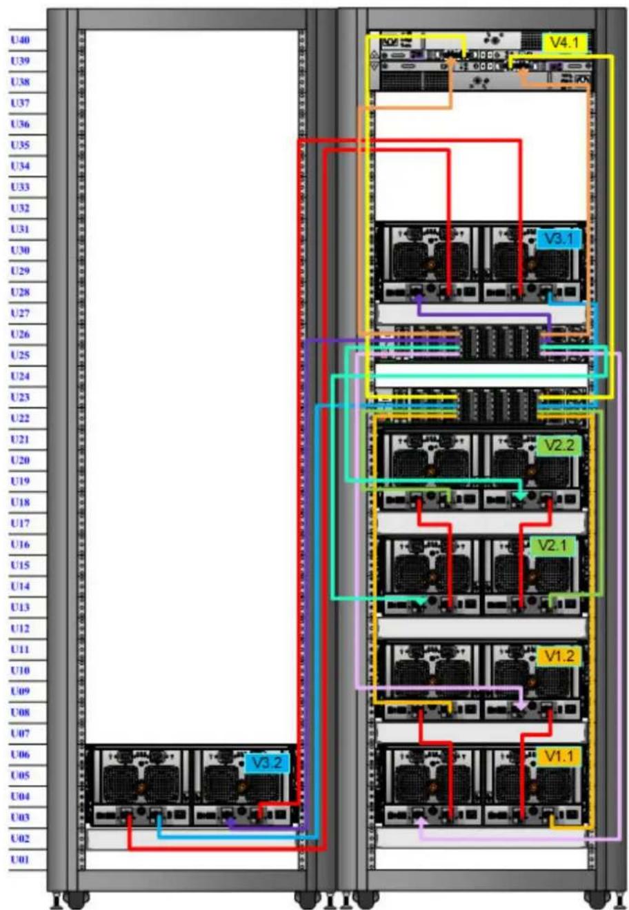
DD6800 and DD9300 with ERSO
| String (Loop) | I/O - Port Shelf | Port Length | a |
| 1 I/O 7 - | Port 0 A controller | port 0 of shelf V1.1 2M | |
| 1 I/O 2 - | Port 0 B controller | port 0 of the highest number shelf in V1 2M | |
| 2 I/O 7 - | Port 1 A controller | port 0 of shelf V2.1 2M | |
| 2 I/O 2 - | Port 1 B controller | port 0 of the highest number shelf in V2 2M | |
| 3 I/O 7 - | Port 2 A controller | port 0 of shelf V3.1 2M | |
| 3 I/O 2 - | Port 2 B controller | port 0 of the highest number shelf in V3 5M | |
| 4 I/O 7 - | Port 3 A controller | port 0 of shelf V4.1 5M | |
| 4 I/O 2 - | Port 3 B controller | port 0 of the highest number shelf in V4 5M |
a. Cable lengths shown are designed for Data Domain racks. Longer cables (up to 5M) can be used.
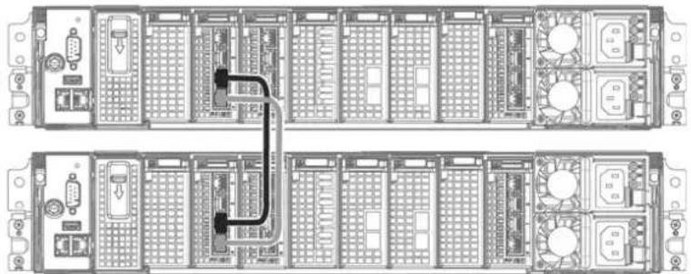
Connecting the HA interconnect
The HA interconnect consists of a 10 GbE I/O module in slot 1 of each node in the HA pair. This connection between the two nodes provides the standby node with the information needed to fail over if the active node suffers a failure, and maintain the connections to hosts and clients after the failover is complete.
Note
- The interconnect IP address is automatically configured with the IPv6 prefix d:d:d:d:/80
- If there is an IP conflict, set the registry key config.net.interconnect_ip6prefix.
Procedure
- Refer to the diagram for the port connections.
Figure 19 HA interconnect
natural_image
Top-down schematic of a server rack layout showing internal components and connections (no text or labels)- Cable port 0 of the interconnect I/O module in node 0, slot 1 to port 0 of the interconnect I/O module in node 1, slot 1.
- Cable port 1 of the interconnect I/O module in node 0, slot 1 to port 1 of the interconnect I/O module in node 1, slot 1.
Installing the front bezel
Procedure
- Align the bezel with the enclosure.
- Gently push the bezel into place on the cabinet until it latches.
- If the bezel has a key lock, lock the bezel the provided key.
Connect data cables
-
Enable data transfer Ethernet connectivity. Repeat for each connection.
a. If using 1 Gb copper Ethernet, attach a Cat 5e or Cat 6 copper Ethernet cable to an RJ-45 Ethernet network port (start with ethMa and go up).
b. If using 10 Gb copper Ethernet with an SFP+ connector, use a qualified SFP+ copper cable.
c. If using 1/10 Gb fiber Ethernet, use MMF-850nm cables with LC duplex connectors.
d. For 10GBaseT connections, use Cat6a S-STP Ethernet cables. -
Enable data transfer Fibre Channel (FC) connectivity. Repeat for each connection.
a. Attach a Fibre Channel fiber optical cable (LC connector) to an I/O module port on the controller, and attach the other end (LC connector) to an FC switch or to an FC port on your server.
Power on all systems
Note
Power on all expansion shelves first before powering on the controller.
- Connect power cables to each expansion shelf receptacle and attach the retention clips.
- Provide power to power on each expansion shelf. The shelves power on when plugged in. Ensure that each shelf power cable is connected to a different power source.
Note
Wait approximately 3 minutes after all expansion shelves are powered on before powering on the controller.
- Provide power to power on the controller. The system powers on when plugged in. The first boot may take several minutes to complete.
Note
DD6300, DD6800, and DD9300 systems should be powered from redundant AC sources. Redundant power sources allow one AC source to fail or be serviced without impacting system operation. PSU0 should be attached to one AC source. PSU1 should be attached to the other AC source.
a. Connect power cables to each receptacle and attach the retention clips.
b. Ensure that each power supply is connected to a different power source.
Connect Cables and Power on
CHAPTER 5
Configure System for Use
- Enable administrative communication....74
• Accepting the End User License Agreement (EULA)....75 - Run the configuration wizard....75
- Configure HA....78
Enable administrative communication
For HA pairs, administrative communication must be enabled on both nodes.
The administrative interfaces are located on the management module on the rear of the chassis. These interfaces are for management network traffic only. Do not use these interfaces for data traffic.
-
Connect an administrative console to the serial port on the back panel of the system.
-
Note
You must have 115200 baud rate for the system to work correctly; 9600 baud rate does not work.
Launch a terminal emulation program from your computer and configure the following communication settings:
Table 48 Communications settings
| Setting Value | |
| Baud rate 115200 | |
| Data bits 8 | |
| Stop bits 1 | |
| Parity None | |
| Flow control None | |
| Emulation VT-100 |
- Press Enter to activate the console.
Note
If you do not see the prompt on your terminal to log in, then complete Step 4.
-
Verify the front blue power LED (blue square) is on. If it is not, make sure the power cables are fully seated at both ends, and both AC sources are on.
-
Note
The initial username is sysadmin and the initial password is the system serial number.
Log in to the Data Domain console using the sysadmin username.
localhost.localdomain login: sysadmin
- Type the default password, which is the system serial number. The Product ID/SN tag is attached beneath the power supply at the rear of the system. See the rear panel of the system for the Product ID/SN tag.
Password: system_serial_number
Note
If you type an incorrect password four consecutive times, the system locks out the specified username for 120 seconds. The login count and lockout period are configurable and might be different on your system. See the Data Domain Operating System Administration Guide and the Data Domain Operating System Command Reference Guide for setting these values.
For Data Domain HA systems, SSH keys created on the active node take 30 seconds to one minute to propagate to the standby node.
Accepting the End User License Agreement (EULA)
The first time you log in to a Data Domain system, the End User License Agreement (EULA) is displayed.
At the end of the EULA, you are prompted to accept it:
Press any key then hit enter to acknowledge the receipt of EULA information
Note
The customer must accept the EULA. A Data Domain representative should not accept this agreement. If a customer is not present, press ctrl-c to exit from the EULA acceptance screen and continue the installation.
The customer can later type the following to redisplay the EULA and accept it:
system show eula
Run the configuration wizard
The CLI configuration wizard starts automatically the first time the system starts. The wizard prompts you through a series of questions that provide just enough information for initial system configuration and basic network connectivity.
Note
You can begin the CLI configuration wizard manually by typing config setup.
Configuring the network
Procedure
- Enter yes to configure the system for network connectivity.
Network Configuration
Configure Network at this time (yes|no) [no]:
yes
- Enter yes to configure DHCP (Dynamic Host Configuration Protocol) to obtain network parameters (such as, the host name, domain name, and IP addresses) dynamically from a DHCP server. Or enter no to configure the parameters manually.
Use DHCP
Use DHCP for hostname, domainname, default gateway and DNS servers? (At least one interface needs to be configured using DHCP) (yes|no|?)
- Enter a fully qualified domain name (FQDN) for the host name; for example, str01.yourcompany.com. Or accept the host name, if the system was able to discover it.
Enter the hostname for this system (fully-qualified domain name)[]:
- Enter the DNS (Domain Name System) domain name; for example, yourcompany.com. Or accept the domain name, if the system was able to discover it.
Domainname
Enter your DNS domainname []:
- Enable and configure each Ethernet interface. Accept or decline DHCP for each interface. If the port does not use DHCP to discover network parameters automatically, enter the information manually.
Ethernet port eth0a
Enable Ethernet port eth0a (yes|no|?) [yes]:
no

Ethernet port eth0b
Enable Ethernet port eth0b (yes|no|?) [no]:
yes

Use DHCP on Ethernet port eth0b (yes|no|?) [no]:
Enter the IP address for eth0b [192.168.10.185]:
Enter the netmask for eth0b [255.255.255.0]:
- Enter the IP address of the default routing gateway. Or accept the default gateway, if the system was able to discover it.
Default Gateway
Enter the default gateway IP address:
192.168.10.1
- Enter the IPv6 address of the default routing gateway. Or accept the IPv6 address of the default gateway, if the system was able to discover it. If IPv6 is not in use, leave the field empty, and press Enter to continue.
IPV6 Default Gateway
Enter the ipv6 default gateway IP address:
- Enter up to three DNS servers to use for resolving host names to IP addresses. Use a comma-separated or space-separated list. Enter a space for no DNS servers. Or accept the IP addresses of the DNS servers, if the system was able to discover them.
DNS Servers
Enter the DNS Server list (zero, one, two or three IP addresses):
192.168.10.1
- A summary of the network settings is displayed. You can accept the settings (Save), reject the settings and exit to the CLI (Cancel), or return to the beginning of the current section and change the settings (Retry). Entering Retry displays your previous responses for each prompt. Press Return to accept the displayed value or enter a new one.
| Pending Network Settings | |||||
| Hostname | ddbetal.dallasrdc.com | ||||
| Domain name | dallasrdc.com | ||||
| Default Gateway | 192.168.10.1 | ||||
| DNS Server List | 192.168.10.1 | ||||
| Port | Enabled | Cable | DHCP | IP Address | Netmask or Prefix Length |
| eth0a | no | no | n/a | n/a | n/a |
| eth0b | no | no | n/a | n/a | n/a |
| eth0c | no | no | n/a | n/a | n/a |
| eth0d | no | no | n/a | n/a | n/a |
| ethMa | yes | yes | no | 192.168.10.181 | 255.255.255.0 |
| ethMb | no | no | n/a | n/a | n/a |
| ethMc | no | no | n/a | n/a | n/a |
| ethMd | no | no | n/a | n/a | n/a |
| ethMe | no | no | n/a | n/a | n/a |
| ethMf | no | no | n/a | n/a | n/a |
| ---- | ---- | ---- | ---- | ---- | ---- |
| Do you want to save these settings (Save|Cancel|Retry): | |||||
Configuring additional system parameters
Most installations would benefit from the configuration of a few additional system parameters, provided in this section for convenience.
Note
You can also use the Data Domain (DD) System Manager GUI interface to configure the system parameters. Open a web browser, and enter your Data Domain system's IP address in the browser's address text box. Log in when the DD System Manager login screen displays. Use the DD System Manager online help for more information.
Procedure
- To set up the mail server, enter:
<h1 id="config-set-mailserver-maildatadomaincom">config set mailserver mail.datadomain.com</h1>
The Mail (SMTP) server is: mail.datadomain.com
- To set up the system location, enter:
<h1 id="config-set-location-dallas-regional-data-center-lab-5000-apple-drive-suite-130-dallas-tx">config set location "Dallas Regional Data Center Lab, 5000 Apple Drive Suite #130, Dallas, Tx"</h1>
The System Location is: Dallas Regional Data Center Lab, 5000 Apple Drive Suite #130, Dallas, Tx
- To add one or more time servers, enter:
<h1 id="ntp-add-timeserver-1921681011">ntp add timeserver 192.168.101.1</h1>
Remote Time Servers: 192.168.10.1
- To enable the NTP daemon, enter:
<h1 id="ntp-enable">ntp enable</h1>
NTP enabled.
- To change the system time zone, enter:
<h1 id="config-set-timezone-uscentral">config set timezone US/Central</h1>
The Timezone name is: US/Central
*** You made a change to the timezone setting. To fully effect this change
*** (in currently running processes), you need to reboot the machine.
- Reboot the system for the time zone change to take effect:
<h1 id="system-reboot">system reboot</h1>
The 'system reboot' command reboots the system. File access is interrupted during the reboot.
Are you sure? (yes|no|?) [no]: yes
ok, proceeding.
The system is going down for reboot.
-
After the system completes the reboot, login again as sysadmin using the serial number as a password. Press ctrl-C to get through the EULA, sysadmin password prompt, and config setup wizard.
-
Generate an autosupport sent to yourself to use as ACG input:
# autosupport send your.email@emc.com
OK: Message sent.
Configure HA
Before you begin
• The HA interconnect between both nodes is connected.
Note
Connecting the HA interconnect on page 69 describes how to cable the HA interconnect.
• The data connections on both nodes are connected.
Configure the two nodes as an HA pair.
Note
Configuring an HA pair sets the system password on the standby node to match the system password on the active node, however, that synchronization is not set until the HA configuration is complete. If the HA configuration fails, or if there is a need to access either node before the HA configuration is complete, use the serial number of each node as the password.
Procedure
-
Identify which node will serve as the primary node.
-
On the primary node, create the HA pairing.
Run the following command:
ha create peer {
Note
- Specify the hostname or the IP address of the standby node.
• Specifying an HA system name: - Assigns node 0 the local hostname
-p0. - Assigns node 1 the local hostname
-p1. - The ha create command will fail if one node is configured to use DHCP and the other node is configured to use static IP addresses. Both nodes must use the same method to configure IP addresses.
ha create peer mysystem-p1.emc.com ha-name mysystem.emc.com
Both nodes reboot, and are configured as an HA pair when they come back up.
- On the primary node, configure one or more floating IP addresses for data access.
Run the following command:
net config
Note
The net config command with the float option is the only way to configure a floating IP address. There is no method available in Data Domain System Manager to configure a floating IP address.
net config ethla 2.2.2.1 netmask 255.255.255.0 type floating
Configure System for Use

- Dell EMC Data Domain DD6300, DD6800, and DD9300 Systems
- CONTENTS
- Figures 5
- Tables 7
- Revision history 9
- Chapter 1 Planning and Site Preparation 11
- Chapter 2 Data Domain DD6300, DD6800, and DD9300 Hardware Overview
- Chapter 3 Install the System in the Rack 39
- Chapter 4 Connect Cables and Power on 49
- Chapter 5 Configure System for Use 73
- FIGURES
- TABLES
- Revision history
- CHAPTER 1
- Planning and Site Preparation
- Tools and supplies needed
- Safety information
- CAUTION
- Data Domain systems are heavy. Use at least two people or a mechanical lift to move any system.
- CHAPTER 2
- Data Domain DD6300, DD6800, and DD9300 Hardware Overview
- Front panel
- Note
- DD6300 front panel
- DD6800 front panel
- DD9300 front panel
- Front LED indicators
- Back panel
- DD6300 rear SSDs
- Rear LED indicators
- I/O modules
- I/O module slot numbering
- Slot 7
- DD6300 slot map
- DD6800 and DD9300 slot map
- I/O module population rules
- Storage capacity
- DD6300 storage capacity
- DD6800 storage capacity
- DD9300 storage capacity
- DD6300 system features
- DD6300 system specifications
- Internal system components
- DIMMs overview
- DD6300 memory DIMM configuration
- DD6800 system features
- DD6800 system specifications
- DD6800 memory DIMM configuration
- DD9300 system features
- DD9300 system specifications
- DD9300 memory DIMM configuration
- CHAPTER 3
- Install the System in the Rack
- Unpack the system
- Rails and cable management assembly
- Identify the rack location to install the system
- Install the rails
- Procedure
- Install the DD6300, DD6800, or DD9300 system into a rack
- Installing the cable management assembly (CMA)
- Installing the expansion shelves into the racks
- CHAPTER 4
- Connect Cables and Power on
- Connecting ES30 shelves
- ES30 cable information
- DD6300
- DD6800 and DD9300 (single node, DD Cloud Tier, or ERSO)
- DD6800 and DD9300 (HA or HA with DD Cloud Tier)
- DD6800 and DD9300 with HA
- DD6800 and with HA and DD Cloud Tier
- DD9300 with DD Cloud Tier or HA and DD Cloud Tier
- Connecting the HA interconnect
- Installing the front bezel
- Connect data cables
- Power on all systems
- CHAPTER 5
- Configure System for Use
- Enable administrative communication
- Accepting the End User License Agreement (EULA)
- Run the configuration wizard
- Configuring the network
- Configuring additional system parameters
- Configure HA
- Before you begin
Brand : DELL
Model : EMC Data Domain 9300
Category : NAS