ITA2 - Uninterruptible Power Supply Liebert - Free user manual and instructions
Find the device manual for free ITA2 Liebert in PDF.


User questions about ITA2 Liebert
0 question about this device. Answer the ones you know or ask your own.
Ask a new question about this device
Download the instructions for your Uninterruptible Power Supply in PDF format for free! Find your manual ITA2 - Liebert and take your electronic device back in hand. On this page are published all the documents necessary for the use of your device. ITA2 by Liebert.
USER MANUAL ITA2 Liebert
Copyright by Vertiv Co. Ltd.
The content in this document is subject to change without notice. All rights, including rights of translation, reproduced by printing, copying or similar methods, and even of parts, are reserved. Violators will be liable for damages. All rights, including rights deriving from patent license or registration of a utility model or design, are reserved. No part of this document may be reproduced or transmitted in any form or by any means without the prior written consent of Vertiv Co. Ltd.
Notice
The purchased products, services, and features are stipulated by the contract made between Vertiv Co., and the customer. All or part of the products, services, and features described in this document may not be within the purchasing scope or the usage scope. Unless otherwise specified in the contract, all statements, information, and recommendations in this document are provided "AS IS" without warranties, guarantees or representations of any kind, either express or implied. The information in this document is subject to change without notice. Every effort has been made in the preparation of this document to ensure the accuracy of the contents, but all statements, information, and recommendations in this document do not constitute a warranty of any kind, express or implied.
Vertiv Co., Ltd.
Website: www.vertivco.com.
- China
E-mail: vertivc.service@vertivco.com
Customer service hotline: 4008876510
- India
E-mail: customer.care@vertivco.com
Customer service hotline: 1800 209 6070
- Asia
Australia - au.service@vertivco.com
New Zealand - au.service@vertivco.com
Philippines - ph.service@vertivco.com
Singapore - sg.service@vertivco.com
Malaysia - my.service@vertivco.com
For Technical Support, users may contact the nearest Vertiv Co. local sales office or service center.
Purpose of the Document
This document applies to the Liebert® ITA2 UPS which is the next generation series of UPS that provides continuous, high quality AC Power to business critical equipment.
This document explains the product description, installation measures, operational workflow, and thorough aspects from the user perspective. The figures used in this document are for reference only.
Please read this manual carefully before installing, maintaining, and troubleshooting, especially the warning information in the manual
Styling used in this Guide
The styles used in the manual will be defined as mentioned in the following table:
| Situation Description | |
Warning/Danger/Caution | The Warning/Danger/Caution note indicates a hazardous or potentially harmful situation that can result in death or injury. It also indicates instructions that need to be adhered to, failing which may result in danger and safety issues thereby having an adverse effect on the reliability of the device and security. Even for practices not related to physical injury, the content under the Warning heading is used for precautions which need to be taken which, otherwise, could result in equipment damage, performance degradation, or interruption in service. |
Note | The Note section indicates additional and useful information including tips and tweaks. It also calls attention to best practices and industry-best protocols that are standardized and help make maximum utilization of the resources at hand. Helpful information related to the mainstream stuff also comes under the Note heading helping the users get to grips with the definitions, concepts, and terminologies used in the manual. |
Version History
| Issue | Revision | Changes |
| 1.9 | ---- |
Special Declaration
Personnel Safety
- This product must be installed and commissioned by professional engineers of the manufacturer or its authorized agent. Failure to observe this could result in product malfunction or personnel safety risk.
- Take the time to read this product manual and the safety precaution thoroughly before installing and commissioning this product. Failure to observe this could result in product malfunction or personnel safety risk.
- This product is not intended for life support equipment application.
- Never dispose of the battery of this product in a fire, as it may explode and jeopardize personnel safety when exposed to flame.
Product Safety
- If this product will be stored or remain de-energized for a long period, it must be placed in a dry and clean environment within specified temperature range.
- This product should be used in an appropriate operating environment. For details, refer to the section on the environmental requirement in this manual.
- This product is not designed for application in an environment:
Where the temperature and relative humidity are outside the specifications
Subject to vibrations or shocks
Where conductive dusts, corrosive gases, salts, or flammable gases are present
Near heat sources or strong electromagnetic interferences
Disclaimer
Vertiv disclaims any and all responsibility or liability for the defects or malfunction caused by:
Application range or operating environment outside the specifications
➢ Unauthorized modification, improper installation or operation
Force majeure
➢ Other actions not in compliance with the instructions in this manual
Safety Precautions
This manual contains the information concerning the installation and operation of Liebert ^® ITA2 ^TM 5kVA \~ 20kVA UPS (hereinafter referred to as UPS). Please read this manual carefully prior to installation.
To reduce the chance of accident, please read the safety precautions very carefully before operation. The 'Caution, Note, Warning' in this user manual and on the product do not represent all the safety points to be observed, and are only supplement to various safety points. Therefore, the installation and operation personnel must receive strict training and master the correct operations and all the safety points before operation.
When operating Vertiv products, the operation personnel must observe the safety rules in the industry, the general safety points and special safety instructions provided by Vertiv.

- The UPS must be installed, commissioned and serviced by engineers designated by the manufacturer or its agent. Failure to observe this could result in personnel safety risk, UPS malfunction and invalidation of warranty.
- The UPS has been designed for commercial and industrial use only, and is not recommended for use in life support applications.
- This is a Class C2 UPS product. In a residential environment, this product may nevertheless cause radio interference, in which case, the user is required to take additional measures to reduce the interference.

Backfeed protection
Before operating the circuit, isolate the UPS firstly and then check the dangerous voltage between the ports, and that between the ports and earth.

Conformity and standards
The UPS complies with 2014/35/EU (LVD), 2014/30/EU (EMC), 2011/65/EU (Rohs) and the following product standards for UPS:
IEC/EN 62040-1, General and safety requirements for UPS
IEC/EN 62040-2: Class C2 compliant
IEC/EN 62040-3: Performance requirements and test methods
The UPS installation should follow the above instructions and use the accessories specified by manufacturer.
For 3-in 1-out mode of 10kVA 230V model, this equipment complies with IEC 61000-3-12 provided that the short-circuit power Ssc is greater than or equal to 3.5MVA at the interface point between the user's supply and the public system. It is the responsibility of the installer or user of the equipment to ensure, by consultation with the distribution network operator if necessary, that the equipment is connected only to a supply with a short-circuit power Ssc greater than or equal to 3.5MVA. For 16kVA/20kVA model, according to EN 61000-3-11, the UPS system is subjected to conditional connection, and the maximum permissible system impedance Zmax at the interface point of the user's supply has been detailed as below:
$$ Z - p h a s e = 0. 0 8 6 \text { Ohm } + j 0. 0 5 4 \text { Ohm } \quad (0. 0 8 6 \text { Ohm } + 1 7 1 \text { uH }) $$
$$ Z - \text { neutral } = 0. 0 5 7 \mathrm{Ohm} + j 0. 0 3 6 \mathrm{Ohm} \quad (0. 0 5 7 \mathrm{Ohm} + 1 1 4 \mathrm{uH}) $$

When the UPS is operating, some parts have high voltage, therefore, contacting with them directly or through moist objects will result in fatal risk.

- Before moving or rewiring the UPS, disconnect mains input power and the battery and make sure that the UPS is completely shut down. Otherwise, the output terminal may carry live voltage, presenting an electric shock hazard
- Liquid or other irrelevant external objects are prohibited inside the UPS.
- In case of a fire, a dry chemical fire extinguisher is essential. Using a foam fire extinguisher will cause electric shock.
- The output neutral line of the UPS is from the input, after the neutral line is suspended by the upstream protection devices, the output neutral line will be unconnected.
- To prevent the radio frequency of output cables from disturbing other electric equipment, it is recommended to use the UPS output cable with the length less than 10m.

High leakage current
- Earth connection is essential before connecting the input power (AC mains and battery included).
- Earth leakage current ranges from 0 to 20mA.
- Transient and steady-state earth leakage currents, which may occur when starting the equipment, should be taken into account when selecting instantaneous Residual Current Circuit Breaker (RCCB) or Residual Current Detector (RCD).
- Note that the earth leakage current of the load will be carried by RCCB or RCD.
- This equipment must be earthed in accordance with the local electrical codes.

- When selecting the UPS system upstream distribution protection equipment, ensure that it complies with the local electric regulations.
- The specified upstream breakers are required to obtain the conditional short-circuit current rating, Icc at 10kA symmetrical rms. The specified upstream breakers should comply with an IEC 60947 series standard.

User serviceable components
- The UPS contains no user-serviceable parts. Do not remove the cover. Removing the cover may result in electric shock and will invalidate any implied warranty.
- The UPS meets the safety requirements completely in operator access area. Only service personnel can contact with the hazardous voltage inside the UPS. However, the risk of contacting these voltages is minimized because the components with hazardous voltage may be contacted only by using a tool to remove the protective cover. No risk will exist if you follow the general norms and in accordance with the procedures recommended in this manual on equipment operation.

Battery high voltage
- All the physical service and maintenance of the battery are performed by the trained technicians.
- Operation on the battery will result in electric shock and high short-circuit current, therefore, before operating the battery, the following should be observed:
Remove the watches, rings and other metal objects.
Use the tools with insulation handle.
- Wear rubber glove and shoes.
Avoid to place the tools and metal objects on the battery surface.
Cut off the charge power supply before connecting or disconnecting the battery terminals.
Check whether the battery is earthed accidentally, if yes, please disconnect the earthing. Contacting any earth battery parts will result in electric shock. Therefore, make sure that the battery is not earthed during installation and maintenance.
- Battery manufacturers provide the details of the precautions to be observed when working on, or in the vicinity of the batteries. These precautions should be followed implicitly at all times. Attention should be paid to the recommendations concerning local environmental conditions and the provision of protective clothing, first aid and fire-fighting facilities.
The Manual Describes The Following Devices
| Product | Model |
| 5kVA | ITA-05k00AL1102P00 (Long back-up model)ITA-05k00AE1102P00 (Standard model) |
| 6kVA | ITA-06k00AL1102P00 (Long back-up model)ITA-06k00AE1102P00 (Standard model) |
| 10kVA | ITA-10k00ALA102P00 (Long back-up model)ITA-10k00AEA102P00 (Standard model) |
| 16kVA | ITA-16k00AL3A02P00 (Long back-up model)ITA-16k00AE3A02P00 (Standard model) |
| 20kVA | ITA-20k00AL3A02P00 (Long back-up model)ITA-20k00AE3A02P00 (Standard model) |
TABLE OF CONTENTS
1 Product Introduction.... 1
1.1 Features.... 1
1.2 Model Configurations 2
1.3 Appearance And Components.... 3
1.3.1 Appearance 3
1.3.2 Components.... 3
1.4 Operating Principle .... 5
1.5 UPS State And Operation Mode....7
1.5.1 Normal Mode 7
1.5.2 Bypass Mode....8
1.5.3 Battery Mode 9
1.5.4 ECO Mode (For Single UPS With External Battery Only) 10
1.5.5 Fault State 10
1.5.6 Maintenance Bypass Mode .... 10
1.6 Specifications....11
2 Single UPS Installation And Commissioning....14
2.1 Unpacking Inspection....15
2.2 UPS Moving ....17
2.3 Installation Preparation....17
2.3.1 Location....17
2.3.2 Environmental Requirement ....17
2.3.3 Installation Tools....19
2.4 External Protective Devices....20
2.4.1 Rectifier And Bypass Input ....20
2.4.2 Battery Input 21
2.4.3 UPS Output 21
2.5 Mechanical Installation 21
2.5.1 Tower Installation 22
2.5.2 Rack Installation....23
2.6 Connecting Power Cables....26
2.6.1 Connecting I/O Cables....29
2.6.2 Connecting Battery Cables....39
2.7 Single UPS Commissioning....44
2.7.1 Check Before Start-Up 44
2.7.2 Start-up Interface 44
2.7.3 Normal Mode Start-Up....45
2.7.4 Battery Mode Start-Up 46
3 Parallel UPS Installation And Commissioning 47
3.1 Features 47
3.2 Requirements....47
3.3 Mechanical Installation 48
3.4 Connecting Power Cables....49
3.4.1 Connecting I/O Cables....50
3.4.2 Connecting Parallel Cables....52
3.4.3 Connecting Battery Cables....53
3.5 Commissioning Parallel System 56
3.5.1 Check Before Start-Up .... 56
3.5.2 Parallel System Parameters Setting ....57
3.5.3 Power-On Commissioning For Parallel System 57
3.6 Installation And Commissioning For Dual Bus System (16kVA/20kVA Only) 59
3.6.1 Introduction ......59
3.6.2 Installing External Protective Device....60
3.6.3 Connecting Power Cables 60
3.6.4 Connecting LBS Cables 61
3.6.5 Setting Parameters Of LBS 62
4 Operation And Display Panel 63
4.1 Introduction....63
4.1.1 LED Indicators....64
4.1.2 Audible Alarm (Buzzer) 64
4.1.3 LCD And Functional Keys 65
4.1.4 Initial Start-up Guidance ......66
4.2 LCD Menu Structure....70
4.3 LCD Screen Types 70
4.3.1 Start Screen....70
4.3.2 Flow Screen....71
4.3.3 Main Menu Screen 71
4.3.4 Submenu Screen 72
4.3.5 Default Screen....76
4.4 Prompt Window....77
4.5 UPS Alarm Message List....78
5 UPS Operation Instructions ....84
5.1 UPS Start-Up 84
5.2 Transfer Procedures Between Operation Modes....84
5.2.1 Transfer From Normal Mode To Battery Mode 84
5.2.2 Transfer From Inverter Mode To Bypass Mode 85
5.2.3 Transfer From Bypass Mode To Inverter Mode 86
5.2.4 Transfer From Inverter Mode To Maintenance Bypass Mode 87
5.2.5 Transfer From Maintenance Bypass Mode To Inverter Mode 88
5.3 UPS Complete Shutdown 89
5.4 REPO 89
5.5 Auto Restart 90
5.6 Language Selection ....90
5.7 Changing Current Date And Time....91
5.8 Setting Password....93
5.9 Changing output configuration ....97
6 Communication....99
6.1 Installing Intelligent Card 99
6.1.1 Intelligent Card Port....99
6.1.2 Intelligent Card Option 99
6.2 Connection Cables For Dry Contact Port 101
6.3 Connecting USB Communication Cables....103
6.4 Connecting Serial Port Communication Cables....103
6.5 Connecting Control Port 103
6.6 Connecting Built-in Ethernet Port....103
7 Maintenance ....105
7.1 Fan Maintenance .... 105
7.2 Battery Maintenance....105
7.3 Cleaning UPS 106
7.4 Checking UPS State....107
7.5 Checking UPS Functions....107
8 Options 108
8.1 Option List....108
8.2 Battery Module 109
8.2.1 List Of Battery Module Options ...... 109
8.2.2 Appearance Of Battery Module 109
8.2.3 Backup Time Of Standard Battery Module For Single UPS....110
8.3 POD 112
8.4 Communication Cables 114
8.5 Guide Rail....115
8.6 Dual Bus Parts 115
8.7 Battery Cabinet....115
8.8 Communication Options And Temperature/Humidity Sensor 117
Appendix 1 LCD Parameters Setting....118
Appendix 2 Glossary 121
Appendix 3 Hazardous Substances And Content......122
1 Product Introduction
Liebert® ITA2™ 5kVA \~ 20kVA UPS (UPS for short) is an intelligent online UPS system with sine wave output developed by Vertiv. The UPS offers reliable and high quality AC power to the precision instrument.
The rack/tower installation can be used depending on your requirements. It is applicable to supplying AC power to small scale computer center, network, communication system, automatic control system and precision instrument.
This chapter introduces the features, model configurations, appearance and components, operating principle, UPS state and operation mode, and specifications of the UPS.
1.1 Features
The UPS features include:
Output power factor is 1, which enhances the UPS load capacity
On-line double conversion efficiency up to 96% and ECO efficiency up to 99%.
Product volume decreased by 30% compared to the previous generation; little space occupied, simple handling and assembly
2U thickness (5kVA/6kVA/10kVA) and 3U thickness (16kVA/20kVA). Tower and rack installation are optional to meet different installation requirements
Capable of parallel connection to achieve up to 3 + 1 parallel redundant power
High-frequency double conversion topology structure, with high input power factor, wide input voltage range, and output immune to grid interference, thus adaptable to areas with unstable mains supply
Full digital control platform and hardware design platform, which can adapt worse unstable mains supply and load impact
Supports 12, 16, 20-block batteries; the long back-up model has a built-in large power charger with 13A charging capacity for fast charging
Provide programmable terminals with cascade protection, to protect the key devices for the customer when the load is heavy
Innovative design of the layout and the whole process greatly promote the reliability of the product; pass high temperature humidity durability experiment test of 1000 hours
Operation and display panel with colorful LCD helps to learn about the UPS operation state and operating parameters. The LCD display will change according to the layout of the model
Integrate Ethernet port, support HTTP protocol, and use the web browser to achieve the remote monitoring, no additional monitoring software required
Full configuration can achieve the functions such as Interlock, external temperature & humidity sensor, and battery module automatic identification
Capable of ECO power supply mode and smart sleep mode, which helps to save energy to the maximum extent
1.2 Model Configurations
The model configurations are shown in Table 1-1.
Table 1-1 Model configurations
| Model | Type | Description | |
| 5kVA | Long back-up model | ITA-05k00AL1102P00 | For single UPS system (5kVA/6kVA/10kVA), six battery modules are configured; for single UPS system (16kVA/20kVA), six groups (each group has two) of battery modules are configured. For 1 + 1 parallel system and above, the external battery cabinet with large capacity is recommended |
| Standard model | ITA-05k00AE1102P00 | ||
| 6kVA | Long back-up model | ITA-06k00AL1102P00 | |
| Standard model | ITA-06k00AE1102P00 | ||
| 10kVA | Long back-up model | ITA-10k00ALA102P00 | |
| Standard model | ITA-10k00AEA102P00 | ||
| 16kVA | Long back-up model | ITA-16k00AL3A02P00 | |
| Standard model | ITA-16k00AE3A02P00 | ||
| 20kVA | Long back-up model | ITA-20k00AL3A02P00 | |
| Standard model | ITA-20k00AE3A02P00 | ||
| Model | Input | Output | Remark |
| 5kVA | Single phase | Single phase | Common input configuration |
| 6kVA | Single phase | Single phase | Common input configuration |
| 10kVA | Single phase Single phase | Common input configuration (default), split bypass configuration | |
| Three-phase | Single phase | Common input configuration, split bypass configuration | |
| 16kVA | Three-phase | Single phase | Common input configuration, split bypass configuration |
| Three-phase Three-phase | Common input configuration (default), split bypass configuration | ||
| 20kVA | Three-phase | Single phase | Common input configuration (default), split bypass configuration |
| Three-phase Three-phase | Common input configuration (default), split bypass configuration | ||
1.3 Appearance And Components
1.3.1 Appearance
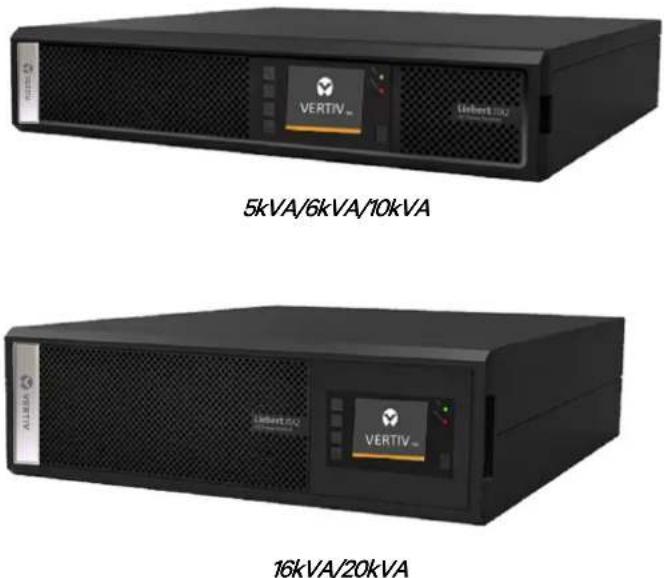
The UPS appearance is shown in Figure 1-1.
text_image
5kVA/6kVA/10kVA 16kVA/20kVAFigure 1-1 Appearance of UPS
1.3.2 Components
Front panel
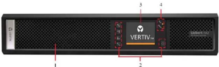
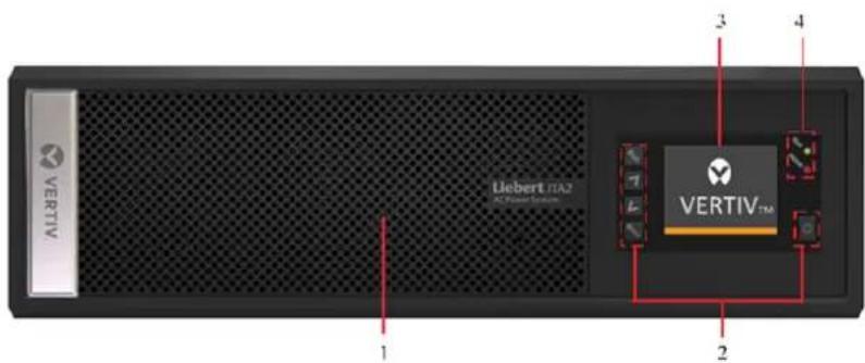
As shown in Figure 1-2, the UPS front panel provides ventilation holes, operation and display panel, LED indicators and functional keys.
text_image
ALBERT 1 2 3 4 VERTIV™ Liebert (BA)-
Ventilation holes 2. Functional keys
-
Operation and display panel
-
LED indicators
5kVA/6kVA/10kVA
text_image
Uebert ITA2 AC Power System 1 2 3 4 VERTIV™-
Ventilation holes
-
Functional keys
-
Operation and display panel
-
LED indicators
16kVA/20kVA
Figure 1-2 UPS front panel
Rear panel
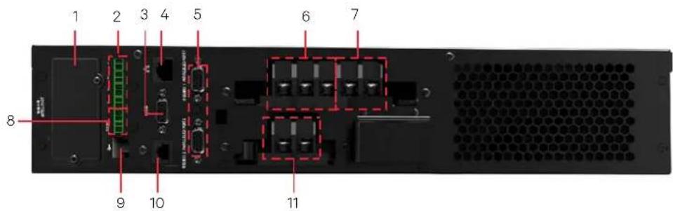
As shown in Figure 1-3, the UPS rear panel provides parallel/LBS ports, dry contact port, I/O terminal block, battery terminal block, Intellislot port, Ethernet port, USB port, RS232 port, REPO port and multi function port. The SlC card in the Intellislot port is optional, purchase it if required.
text_image
1 2 3 4 5 6 7 8 9 10 11-
Intellislot port
-
Dry contact port
-
RS232 port
-
Ethernet port
-
Parallel port
-
AC output port
-
AC input port
-
REPO port
-
USB port
-
Multifunction port
-
Battery input port
5kVA/6kVA
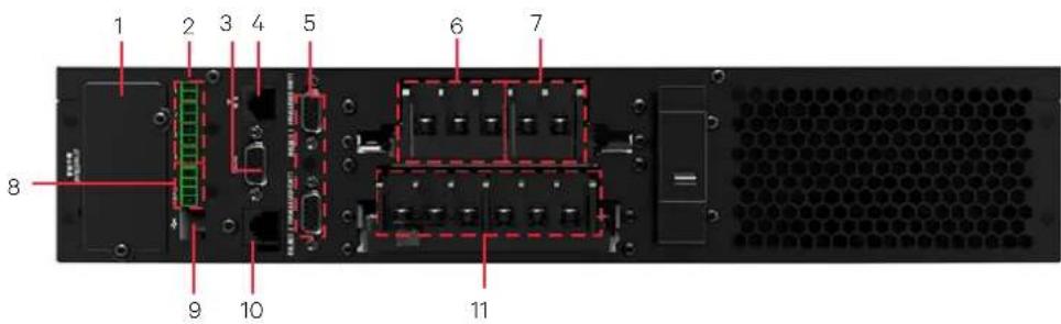
text_image
1 2 3 4 5 6 7 8 9 10 11-
Intellislot port
-
Dry contact port
-
RS232 port
-
Ethernet port
-
Parallel port
-
AC output port
-
Battery input port
-
REPO port
-
USB port
-
Multifunction port
-
AC input port
10kVA
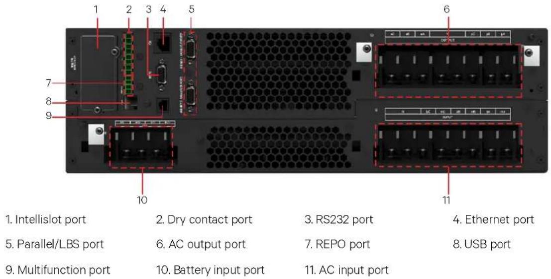
text_image
1. Intellislot port 2. Dry contact port 3. RS232 port 4. Ethernet port 5. Parallel/LBS port 6. AC output port 7. REPO port 8. USB port 9. Multifunction port 10. Battery input port 11. AC input port16kVA/20kVA
Figure 1-3 UPS rear panel

Non-authorized personnel are prohibited from opening the UPS chassis cover.
1.4 Operating Principle
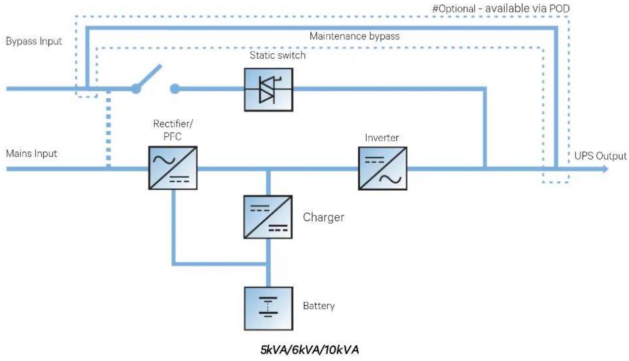
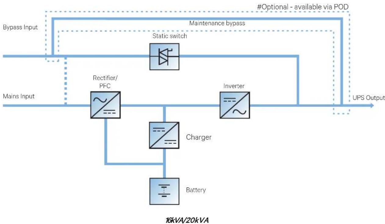
The operating principle of the UPS is shown in Figure 1-4.
flowchart
graph LR
    A["Mains Input"] --> B["Rectifier/ PFC"]
    B --> C["Static switch"]
    C --> D["Inverter"]
    D --> E["Battery"]
    E --> F["Charger"]
    F --> G["5kVA/6kVA/10kVA"]
    H["Bypass Input"] --> I["Maintenance bypass"]
    I --> J["#Optional - available via POD"]
    J --> K["UPS Output"]
flowchart
graph LR
    A["Mains Input"] --> B["Rectifier/ PFC"]
    B --> C["Charger"]
    C --> D["Battery"]
    D --> E["Inverter"]
    E --> F["#Optional - available via POD"]
    F --> G["Static switch"]
    G --> H["Bypass Input"]
    H --> I["Maintenance bypass"]
    I --> J["UPS Output"]
    style A fill:#f9f,stroke:#333
    style B fill:#ccf,stroke:#333
    style C fill:#cfc,stroke:#333
    style D fill:#fcc,stroke:#333
    style E fill:#cff,stroke:#333
    style F fill:#ffc,stroke:#333
    style G fill:#fcf,stroke:#333
    style H fill:#cff,stroke:#333
    style I fill:#ffc,stroke:#333
Figure 1-4 UPS operating principle
- The UPS is composed of mains input (main and bypass), rectifier/PFC, charger, inverter, bypass, battery, DSP controller, and output.
- When the mains is normal, the rectifier will start, and the charger will charge the battery string. Before turning on the UPS, the output voltage is bypass voltage, and the mains supplies power to the load through the bypass. After turning on the UPS, the electronic transfer switch connects the inverter output to the load, and the mains supplies DC power to the inverter through the rectifier/PFC circuit. The inverter then converts DC power into pure sine wave AC power, and supplies the AC power to the load through the electronic transfer switch.
- When the mains is outside the UPS input supply tolerance levels, the battery supplies the required power to the load through the rectifier/PFC circuit where the battery voltage is boosted, and then supplies to the Inverter where it converts DC into pure sinewave AC power.
- After the input mains returns within tolerance levels, the UPS will automatically transfer from Battery mode to Normal mode, the mains supplies DC power to the inverter through the rectifier/PFC circuit, and then the electronic transfer switch supplies AC power to the load.
1.5 UPS State And Operation Mode
For the LED indicators introduced in this section, refer to 4.1.1 LED Indicators.
The UPS state and operation mode include: Normal mode, Bypass mode, Battery mode, ECO mode, Fault state and Maintenance Bypass mode. The operation schematic diagrams of Normal mode, Bypass mode, Battery mode and Maintenance Bypass mode are shown in Figure 1-5 to Figure 1-8.

Maintenance bypass mode is activated only when the UPS output power distribution unit (POD in short) is selected.
1.5.1 Normal Mode
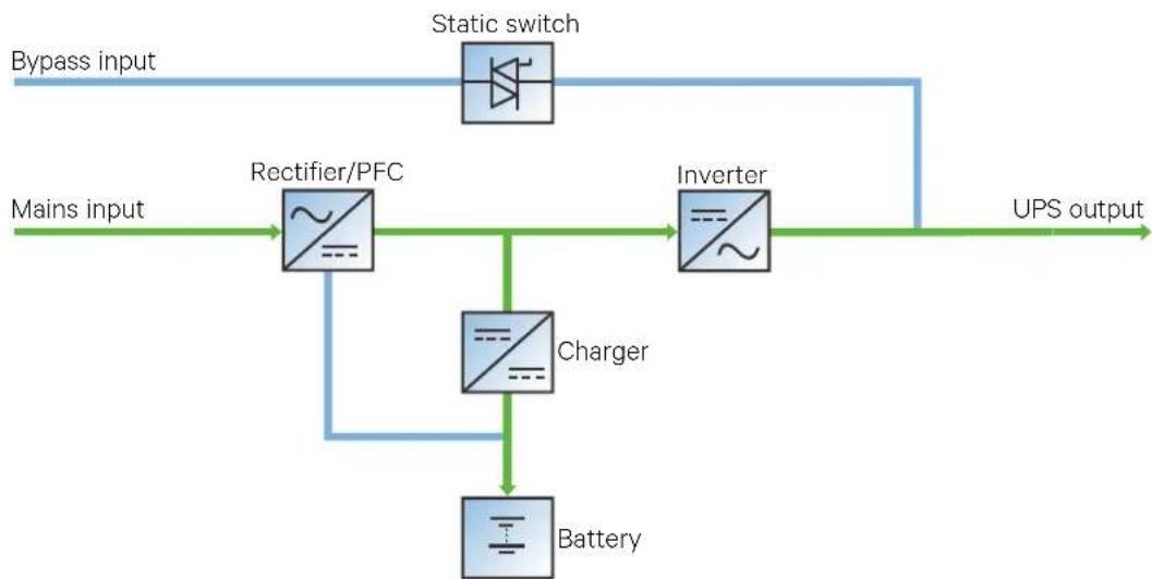
When the mains input is normal, the load is supplied with voltage-stabilizing and frequency-stabilizing power by the mains after processing of the rectifier and the inverter, and meanwhile, the charger is charging the battery. This operation mode is Normal mode.
In Normal mode, the run indicator (green) is ON, the alarm indicator is OFF, and the buzzer is silenced.
flowchart
graph LR
    A["Bypass input"] --> B["Static switch"]
    C["Mains input"] --> D["Rectifier/PFC"]
    D --> E["Charger"]
    E --> F["Battery"]
    G["Inverter"] --> E
    E --> H["UPS output"]
Figure 1-5 Normal mode
1.5.2 Bypass Mode
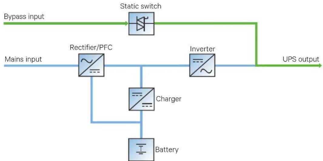
If the overload overtime, inverter or rectifier failure occurs during the UPS operation in Normal mode, the UPS will be transferred to Bypass mode, i.e. the load is powered by the bypass source, which comes directly from the mains input. If the rectifier is normal, the internal charger will charge the battery.
In Bypass mode, the run indicator (green) is ON, alarm indicator (yellow) is ON, and the buzzer beeps every second. The 'Current' page in LCD will display 'On Bypass'.
flowchart
graph LR
    A["Bypass input"] --> B["Static switch"]
    C["Mains input"] --> D["Rectifier/PFC"]
    D --> E["Charger"]
    E --> F["Battery"]
    G["Inverter"] --> H["UPS output"]
    I["Battery"] --> E
Figure 1-6 Bypass mode

In case of mains failure or mains voltage is out of range in Bypass mode, the UPS will shut down and stop the output.
1.5.3 Battery Mode
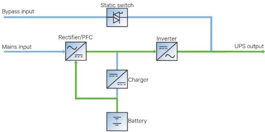
Upon mains failure or voltage out of range, the rectifier and internal charger will stop running, and the battery will supply power to the load through the inverter. In Battery mode, the run indicator (green) is ON, alarm indicator (yellow) is ON, and the buzzer beeps every second. The 'Current' page in LCD will display 'On Battery'.
flowchart
graph LR
    A["Bypass input"] --> B["Rectifier/PFC"]
    C["Mains input"] --> B
    B --> D["Charger"]
    D --> E["Battery"]
    E --> F["Inverter"]
    F --> G["UPS output"]
    H["Static switch"] --> B
Figure 1-7 Battery mode

-
The battery has been fully charged before delivery. However, some loss of capacity is inevitable during transportation and storage. Therefore, it is important to charge the battery for eight hours before the UPS is first put into operation to ensure it can provide adequate backup time.
-
The Liebert ITA2 UPS supports cold start function, while this function is activated, UPS can be powered using battery mode without availability of input power supply. Therefore, the battery power can also be utilized independently for improving the system availability.
1.5.4 ECO Mode (For Single UPS With External Battery Only)
In ECO mode, the load is powered by bypass when the bypass voltage is normal, and the load is powered by inverter when the bypass voltage is abnormal. ECO mode is an energy-saving operation mode. For power equipment that is insensitive to power grid quality, use the ECO mode for power supply through bypass to reduce the power loss.

- In ECO mode, if the bypass fails or abnormal bypass voltage appears when the output is not overloaded, the UPS is transferred to Normal mode. However, if the bypass fails or abnormal bypass voltage appears when the output is overloaded, the UPS will not be transferred to Normal mode, but will shut down the bypass.
- In ECO mode, the efficiency of the UPS is up to 99%.
1.5.5 Fault State
In Normal mode, the load on the UPS is transferred to Bypass mode if the inverter fails or UPS over-temperature appears. In Battery mode (with no bypass mains), the UPS will shut down and stop the output if the inverter fails or UPS over-temperature appears. In UPS Fault state, the alarm indicator (red) will be solid ON, the buzzer will keep beeping, and the corresponding fault information will be displayed on LCD.
1.5.6 Maintenance Bypass Mode (With an optional POD)
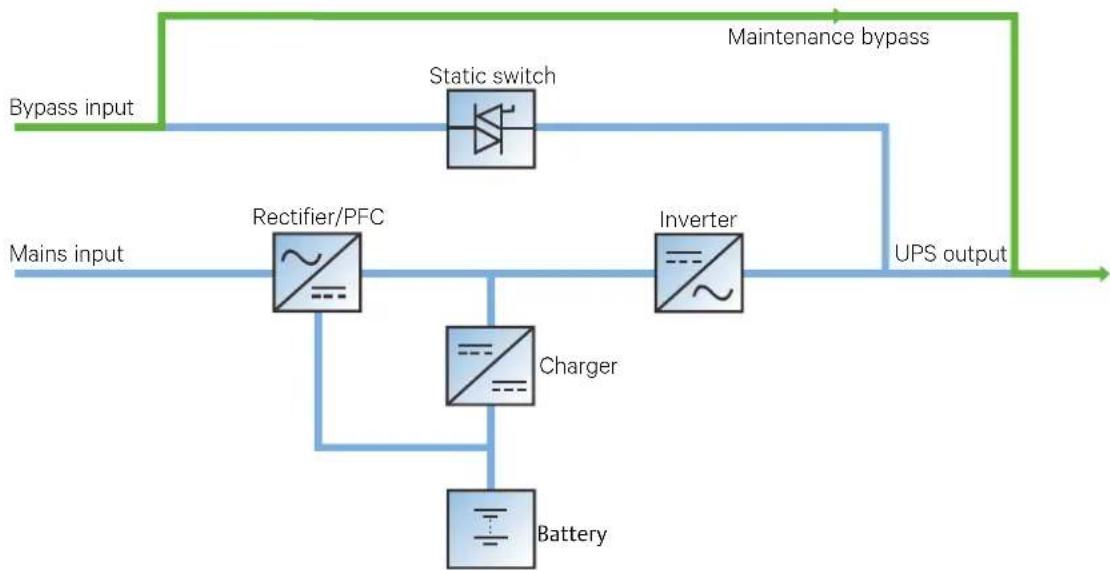
In case when UPS needs to be maintained/reapired online, Load can be transferred to the maintenance bypass using maintenance bypass MCB located on the front panel of the POD. The POD capacity must meets the requirements of total load demand.
Refer to Liebert ITA2 ^TM 5 & 6kVA UPS POD Unit User Manual, Liebert ITA2 ^TM 10kVA UPS POD Unit User Manual, and Liebert ITA2 ^TM 16 & 20kVA UPS POD Unit User Manual for detailed instructions.
flowchart
graph LR
    A["Bypass input"] --> B["Static switch"]
    B --> C["Maintenance bypass"]
    C --> D["UPS output"]
    D --> E["Rectifier/PFC"]
    E --> F["Charger"]
    F --> G["Battery"]
    G --> E
    E --> H["Inverter"]
    H --> C
    style A fill:#f9f,stroke:#333
    style C fill:#ccf,stroke:#333
    style D fill:#cfc,stroke:#333
Figure 1-8 Maintenance bypass mode

In the event of UPS malfunctions or abnormal operation, contact your nearest Vertiv branch office or local service center. NEVER attempt to repair the UPS yourself, as this may result in injury to personnel and/or damage to equipment.
1.6 Specifications
The specifications are listed in Table 1-2.
Table 1-2 Specifications
| Item | Specifications | |||
| 5kVA/6kVA | 10kVA | 16kVA/20kVA | ||
| Input | Rated voltage | 220Vac/230Vac/240Vac | 220Vac/230Vac/240Vac380Vac/400Vac/415Vac | 380Vac/400Vac/415Vac |
| Voltage range | 176Vac ~ 288Vac, at full load100Vac ~ 176Vac, linear derating100Vac, at half load | |||
| Rated frequency | 50Hz/60Hz | |||
| Frequency range | 40Hz ~ 70Hz | |||
| Power factor | ≥0.99, at full load; ≥0.98, at half load; ≥0.95, at full load for 10kVA(3-in 1-out) | |||
| Output | Rated power | 5kW/6kW | 10kW | 16kW/20kW |
| Voltage | 220Vac/230Vac/240Vac (Single phase output) | 220Vac/230Vac/240Vac (single phase output), 380Vac/400Vac/415Vac (three phase output) | ||
| Frequency synchronization range | Rated frequency±3Hz. Configurable range: ±0.5Hz ~ ±5Hz | |||
| Frequency track rate | 0.5Hz/s. Configurable range: 0.2/0.5/1Hz/s (single UPS), 0.2Hz/s (parallel system) | |||
| Rated power factor | 1 | |||
| Crest factor | 3:1 | |||
| Voltage harmonic distortion | < 2% (linear load); < 5% (non-linear load) | |||
| Dynamic response recovery time | 60ms 60ms 40ms | |||
| Overload capacity | At 25°C: 105% ~ 125%, 5min; 125% ~ 150%, 1min; 150%, 200ms | |||
| Bypass voltage | Upper limit: +10%, +15% or +20%; default: +20%Lower limit: -10%, -20%, -30% or -40%; default: -40% | |||
| Mains efficiency | up to 95.5% | up to 95.8% | up to 96.2% | |
| Battery | Type | Sealed, lead-acid, maintenance-free battery | ||
| Cell No. | 12, 16, 20; 16 by default | 24, 32, 40; 32 by default | ||
| Rated voltage | 144Vdc ~ 240Vdc | 144Vdc ~ 240Vdc | 288Vdc ~ 480Vdc | |
| Charge current | ≤ 5A (Long back-up model)≤ 2A (Standard model) | ≤ 8A (Long back-up model)≤ 4A (Standard model) | ≤ 13A (Long back-up model)≤ 5A (Standard model) | |
| Transfer time | Mains←→Battery | 0ms | ||
| Inverter←→Bypass | Synchronous transfer: ≤0msAsynchronous transfer (default): ≤20msOr 40ms, 60ms, 80ms, 100ms and 200ms are available | |||
| Noise | < 55dB (5kVA/6kVA/10kVA); < 58dB (16kVA/20kVA) | |||
| Panel display mode | Colorful LCD | |||
| Safety | IEC/EN62040-1 | |||
| EMC | Conduction emission | IEC/EN62040-2 | ||
| Harmonic current | IEC/EN61000-3-12 | |||
| Surge protection | IEC/EN-61000-4-5, endurance level 4 (4kV) (live line to earth), level 3 (2kV) (during live lines);ANSI C62.41, 6kV/2Ohms | |||
| Protection level | IP20 | |||
| Ambient condition | Operating temperature | 0°C ~ 50°C (0.7 will be derated when above 50°C) | ||
| Storage temperature | -40°C ~ +70°C (battery excluded); -25°C ~ +55°C (battery included) | |||
| Relative humidity | 5%RH ~ 95%RH, non-condensing | |||
| Altitude | ≤3000m; derating when higher than 3000m | |||
| Size | W*D*H (mm) | 430*450*85 | 430*560*85 | 430*570*130 |
| Weight | Net weight (kg) | 11 | 15 | 23 |
| Gross weight (kg) | 13 17 37.5 | |||
2 Single UPS Installation And
Commissioning
This chapter introduces the installation, cable connection and commissioning of the single UPS.
Each site has its own peculiarity, so this chapter provides general installation procedures and methods for the installation engineer who should conduct the installation according to the actual conditions.

- The UPS should be installed by a qualified engineer in accordance with the information provided in this section. In the event of any problems, contact your local Vertiv service center immediately.
- The UPS must NOT be switched ON without the approval of the commissioning engineer.
- For other equipment which is not introduced in this manual, the detailed information about mechanical installation and electrical installation are delivered with the equipment.

3-phase 5-line for power input
The UPS can be connected to 3-phase 5-line (A, B, C, N, PE) TN, TT and IT AC power distribution system (IEC60364-3).
2.1 Unpacking Inspection
5kVA/6kVA/10kVA UPS
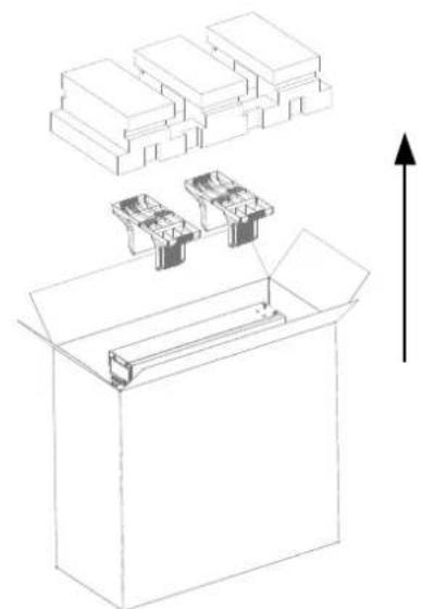
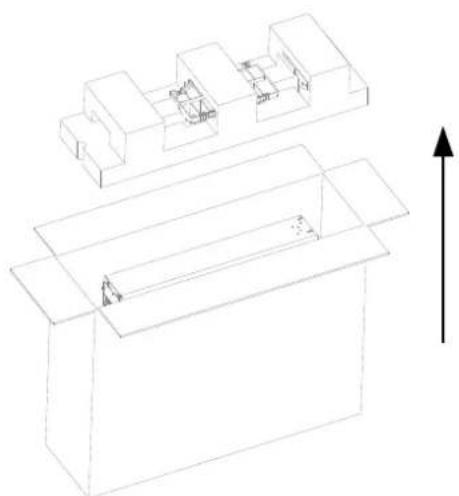
The 5kVA/6kVA/10kVA model adopts the cardboard packaging.
Vertically place the cardboard box, unpack the cardboard box and remove the UPS. See Figure 2-1 and Figure 2-2.
natural_image
Technical line drawing of a box with internal components and an upward arrow, no text or symbols presentFigure 2-1 Unpacking cardboard box (5kVA/6kVA)
natural_image
Technical line drawing of a mechanical assembly with no visible text or symbolsFigure 2-2 Unpacking cardboard (10kVA)
16kVA/20kVA UPS
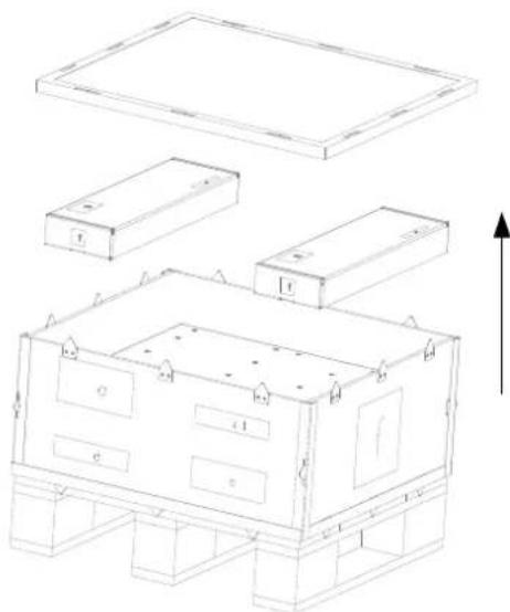
The 16kVA/20kVA UPS adopts the wooden box. Unpacking steps are as follows:
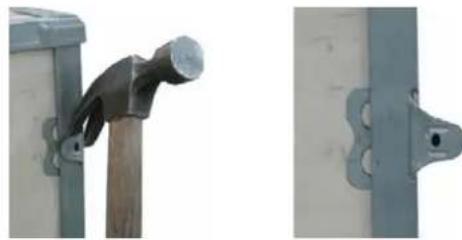
- Remove the side panels and top cover.
Use a hammer or straight screwdriver to straighten the connection hook that connects the side panels to the top cover, as shown in Figure 2-3.
natural_image
Close-up of a metal nail being held by a wooden post, next to a separate view of a metal bracket (no text or symbols visible)Figure 2-3 Straightening the hook
- Dismantle the cover plate of the cardboard box, and remove the UPS, as shown in Figure 2-4.
natural_image
Technical line drawing of a modular building or enclosure with multiple rectangular components and mounting base (no text or symbols)Figure 2-4 Unpacking cardboard box (20kVA)
Then you should check the following items:
- Visually inspect the UPS appearance for transportation damage. If any problem is found, please notify the carrier immediately.
- Check the accessories and models against the delivery list. If any problem is found, please notify the dealer immediately.
2.2 UPS Moving

It is prohibited to move the UPS through the brackets.
The UPS cabinet can be moved by human, or forklift or other similar lifting equipment.
2.3 Installation Preparation
2.3.1 Location
In order to extend the UPS life, the selected place must offer:
- Convenient wiring
Adequate operator access area
Good ventilation to meet the heat dissipation requirements
No corrosive gas, such as sulfur dioxide and so on
No excessive moisture or heat source
No excessive dust
Compliance with fire-fighting requirements
Operating temperature compliant with the specifications, see Table 1-2 for details
2.3.2 Environmental Requirement
UPS room
The UPS is designed for indoor installation, which should be installed in a clean and well-ventilated environment, to keep the ambient temperature within the specifications.
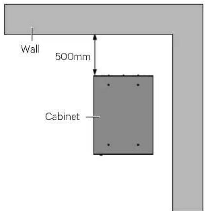
The internal fans provide forced air cooling for the UPS. Cooling air enters the UPS through the ventilation holes on the front panel, and exhausts the hot air through the back ventilation holes. Therefore, do not obstruct the ventilation holes. Maintain at least 200mm clearances between the front, rear of the UPS and the wall or adjacent equipment (see Figure 2-5), to avoid obstructing the UPS ventilation and heat dissipation. Otherwise, the UPS internal temperature will rise, which will shorten the UPS life.
If necessary, an indoor exhaust fan should be installed to keep the indoor temperature from rising. An air filter should be used in a dusty environment where the UPS is to be operated.
Space reserved
text_image
Wall 500mm CabinetFigure 2-5 Installation clearances (top view of rack installation)

-
The UPS should only be installed on concrete or other non-flammable surfaces.
-
As shown in Figure 2-5, the demonstration of the clearance between the rear panel of the cabinet and the wall is 500mm. The clearance should not be less than 200mm, it needs to be considered according to the actual situation for the sake of maintenance convenience.
Battery room
A small amount of hydrogen and oxygen will be generated at the end of battery charging, therefore, you must ensure that the fresh air ventilation of battery installation environment meets the EN50272-2001 requirements.
The battery ambient temperature should keep constant, for the ambient temperature is the main factor to affect the battery capacity and life. The battery standard operating temperature is 20^ C, operation above this temperature will shorten the battery life, and operation below this temperature will reduce the battery capacity. If the battery average temperature in operation rises from 20^ C to 30^ C, the battery life will be reduced by 50%; if the battery temperature in operation exceeds 40^ C, the battery life will be decreased exponentially. In normal situation, the allowable ambient temperature for the battery is between 15^ C to 25^ C. The battery should be kept away from heat source and air outlet.
When the UPS uses an external battery, you must install a battery protective device (such as fuse or circuit breaker) close to the battery, and use the shortest wiring distance for the connection between the protective device and the battery.
Storage environment
When the UPS does not need to be installed immediately, the UPS must be stored indoors to be protected from the excessive moisture or over-temperature environment. The battery requires dry and low temperature, well-ventilated environment for storage, and the most suitable storage temperature is 20^ C \~ 25^ C.

Battery hazards
During the battery storage, the battery must be periodically charged according to the battery instructions. When charging the battery, you can connect the UPS to the mains temporarily to charge and activate the battery.
2.3.3 Installation Tools

- For the sake of safety, the installation tools under live operation must be insulated.
- Tools in Table 2-1 are for reference only; please follow the actual requirement for on-site installation and connection.
Table 2-1 Tools
| Name | Drawing | Name | Drawing |
| Electric hand drill |  | Adjustable wrench |  |
| Slotted screwdriver |  | Cross head screwdriver |  |
| Stepladder |  | Forklift |  |
| Drill |  | Wire cutting plier |  |
| Claw hammer |  | Diagonal cutting plier |  |
| Insulating shoes |  | Antistatic gloves |  |
| Electrician knife |  | Cable tie |  |
| Insulating tape |  | Insulating gloves |  |
| Crimping plier |  | Heat shrinkable tube |  |
| Insulated torque wrench |  | Torque screwdriver |  |
| Multimeter |  | Clip-on ammeter |  |
2.4 External Protective Devices
The circuit breaker or other protective devices must be installed at the external AC input end of the UPS. This section provides the general guidance for qualified installation engineer. The qualified installation engineer should learn about the local wiring regulations and other related information.
2.4.1 Rectifier And Bypass Input
Overcurrent
The appropriate over-current protective device should be installed on the mains input power distribution, and the current capacity of power cable and the system overload requirements should be taken into account during installation (see Table 2-2). For the thermomagnetic circuit breaker, see Table 2-4.
Split-bypass
When the system uses split-bypass, separate protective devices should be installed for the mains and bypass at the mains input power distribution.
Main/Bypass backfeed protection
The UPS has main/bypass backfeed protection function.

- The same neutral line must be used for the rectifier and bypass input power.
- For IT power grid system, the 4-pole protective device for 3-phase UPS must be installed at the UPS external I/O power distribution while the 2-pole protective device for 1-phase UPS must be installed at the UPS external I/O power distribution.
Earth leakage current

The earth leakage current fed by the RFI filter in the UPS, ranges from 0-20mA. Since earth leakage current is high which can cause false tripping of the Circuit breaker. Therefore, we do not recommend to use the MCB with leakage current protection at upstream.
2.4.2 Battery Input
If the battery module option is provided by Vertiv, the battery module has a built-in overcurrent protective device. Otherwise, the external battery cabinet should provide DC compatible circuit breaker to provide the over-current protection for the UPS and its batteries.
2.4.3 UPS Output
The protective device must be installed for the UPS output power distribution. The protective device specification is shown in Table 2-4.
2.5 Mechanical Installation
Two installation modes are available: tower installation and rack installation. You can select an appropriate installation mode according to the actual conditions.
2.5.1 Tower Installation
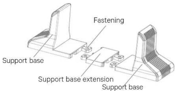
- Take out the support bases from the accessories, assemble a pair of support bases and a support base extension (accessory, for 16kVA/20kVA model use only) together through the fastenings, as shown in Figure 2-6, and place them onto the flat installation table.
text_image
Fastening Support base Support base extension Support baseFigure 2-6 Connecting the support base with support base extension
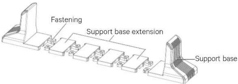
- If battery module installation is necessary, take out other support base extensions supplied with the battery module, and then assemble the support base extensions and the support bases through the fastenings, as shown in Figure 2-7.
text_image
Fastening Support base extension Support baseFigure 2-7 Connecting the support base with support base extension
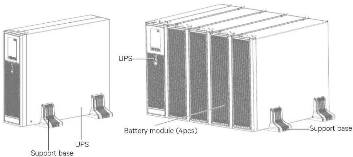
- Place the UPS on the support bases and support base extensions, as shown in Figure 2-8.
text_image
Support base UPS UPS Battery module (4pcs) Support baseFigure 2-8 UPS and battery module Installation complete
2.5.2 Rack Installation
Installation procedures for UPS
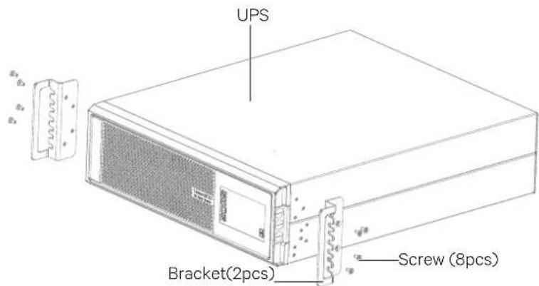
- Use eight M4 × 10 screws to fix two brackets (accessories) respectively on both sides of the UPS front panel, as shown in Figure 2-9.
text_image
UPS Bracket(2pcs) Screw (8pcs)Figure 2-9 Installing brackets

It is prohibited to move the UPS through the brackets.
- Install the guide rails.
You need to use guide rails when you select Liebert® ITA2™ series UPS and its options, and select the rack installation.
The installation procedures of the guide rails are as follows:
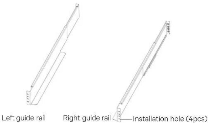
a) Take out the guide rails (one left guide rail and one right guide rail), guide rail screws and panel screws from the package, distinguish the left guide rail and right guide rail according to Figure 2-10, and confirm its retractable function respectively.
text_image
Left guide rail Right guide rail —Installation hole (4pcs)Figure 2-10 Appearance of the guide rail
The guide rail screw is shown in Figure 2-11.


Guide rail screw
Figure 2-11 Appearance of the guide rail screw
b) Adjust the length of the guide rail according to the dimensions of the rack.
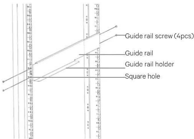
c) Align the installation holes of the guide rail with the square holes of the rack, fix the guide rail onto the rack through the guide rail screws (totally eight), each left guide rail and right guide rail need four guide rail screws, as shown in Figure 2-12.
text_image
Guide rail screw (4pcs) Guide rail Guide rail holder Square holeFigure 2-12 Installing the guide rail

- The guide rail holder must be close to the front of the rack.
- Any end of one guide rail has four installation holes (see Figure 2-10), do not use the two installation holes in the middle when fixing the guide rail. It is recommended to use the top and bottom installation holes (from top to bottom, installation hole 1 and installation hole 4).
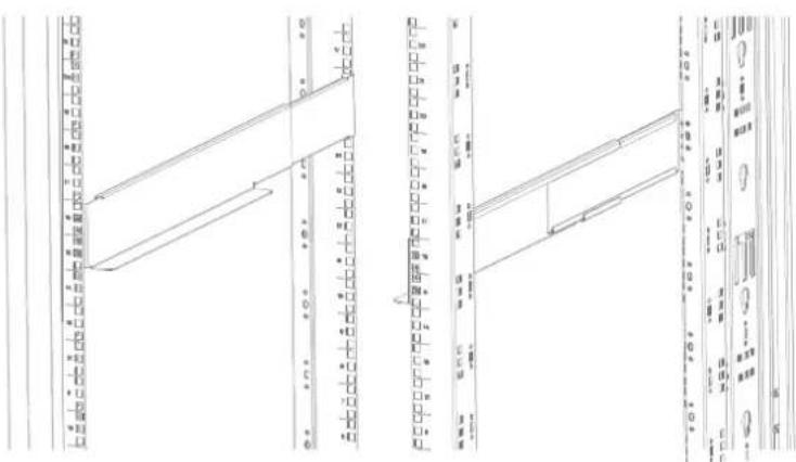
The guide rail installation is finished, as shown in Figure 2-13.
text_image
Technical drawing with dimension annotations and structural components, likely from an engineering or architectural drawing.Figure 2-13 Guide rail installation completed
- Place the UPS on the guide rails in the rack, and push it completely into the rack. Use four M6 × 16 screws to fix the UPS in the rack through the brackets, as shown in Figure 2-14.
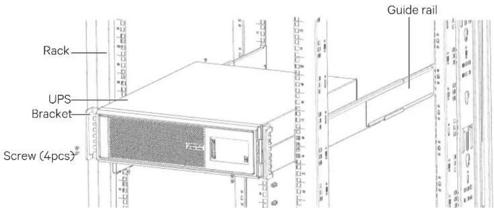
text_image
Rack UPS Bracket Screw (4pcs) Guide railFigure 2-14 Installing the UPS
Installation procedures for UPS with battery modules
The installation method of the battery module is the same as that of the UPS. Repeat the preceding procedures to install and fix the four battery modules and a UPS in the rack one by one, as shown in Figure 2-15.
As the battery module is heavy, pay attention to the following items during installation:
First install the battery modules, start the installation from the bottom, and then place the UPS at the top, as shown in Figure 2-16.
It is prohibited to move the UPS and battery modules through the brackets.
Two or more personnel are required for the installation.
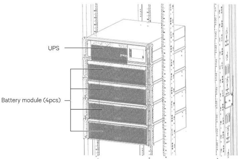
text_image
UPS Battery module (4pcs)Figure 2-15 Installation of UPS with battery modules
2.6 Connecting Power Cables
I/O cables and battery cables are required for connection. When connecting the cables, you should follow the local wiring regulations, take the environment situation into account, and refer to Table 3B of IEC60950-1.
The max. current in different operating modes is listed in Table 2-2, the recommended min. cable CSA is listed in Table 2-3. Select the appropriate cables according to Table 2-2 and Table 2-3.
Table 2-2 Max. steady state AC and DC current
| UPS rated power (kVA) | Rated current (A) | ||||||
| Max. input phase current^1,2 | Max. output phase current^2 | Max. battery discharging current (A) | |||||
| 220V | 230V | 240V | 220V | 230V | 240V | ||
| 5 (1-in 1-out) | 32 | 30 | 29 | 23 | 22 | 21 | 29 |
| 6 (1-in 1-out) | 36 | 35 | 34 | 28 | 27 | 25 | 35 |
| 10(1-in 1-out) | 60 | 58 | 58 | 46 | 44 | 42 | 58 |
| 10(3-in 1-out) | 20 | 20 | 20 | 46 | 44 | 42 | 58 |
| 16(3-in 3-out) | 34 | 32 | 30 | 25 | 24 | 23 | 47 |
| 16(3-in 1-out) | 34 | 32 | 30 | 73 | 70 | 67 | 47 |
| 20(3-in 3-out) | 44 | 43 | 42 | 31 | 30 | 29 | 58 |
| 20(3-in 1-out) | 44 | 43 | 42 | 91 | 88 | 85 | 58 |

When the battery cables are selected, the maximum allowable voltage drop is 4Vdc according to the current value shown in this Table 2-2. Do not ring the cables to avoid increasing the electromagnetic interference (EMI).
1: The input mains current of the rectifier and the bypass.
2: Non-linear load (switch mode power) affects the neutral cable design of the output and the bypass. The neutral cable current may exceed the rated phase current, up to 1.732 times as large as the rated current.
Table 2-3 Single UPS cable CSA (unit: mm², ambient temperature: 25°C)
| Model | Input | Output | Bypass | Neutral cable | PE Battery | Battery PE |
| 5kVA (1-in 1-out) | 4 | 4 | / | 4 | 4 | 4 |
| 6kA (1-in 1-out) | 6 | 6 | / | 6 | 6 | 6 |
| 10kVA (1-in 1-out) | 10 | 10 | 10 | 10 | 10 | 10 |
| 10kVA (3-in 1-out) | 10 | 10 | 10 | 10 | 10 | 10 |
| 16kVA (3-in 1-out) | 10 | 16 | 16 | 16 | 16 | 10 |
| 16kVA (3-in 3-out) | 10 | 10 | 10 | 10 | 10 | 10 |
| 20kVA (3-in 1-out) | 10 | 25 | 25 | 25 | 25 | 10 |
| 20kVA (3-in 3-out) | 10 | 10 | 10 | 10 | 10 | 10 |
| CSA (unit: mm2) | Terminal type |
| 4 | OT4-6 |
| 6 | OT6-6 |
| 10 | RNBS8-6 |
| 16 | RNBS14-6 |
| 25 | RNBS22-6 |
The recommended I/O MCB capability of the UPS is listed in Table 2-4; select the MCBs according to your requirements.

The earth leakage current of the UPS can cause false tripping of the input Circuit breaker. Therefore, we do not recommend to use an MCB with leakage current protection at upstream of UPS.

The specified upstream breakers below are required to obtain the conditional short-circuit current rating, Icc at 10kA symmetrical rms. The specified upstream breakers should comply with an IEC 60947 series standard.
Table 2-4 UPS I/O MCB selection
| Model | Input interface | Recommended capability of input external MCB | Battery MCB | Output interface | Recommended capability of output external MCB |
| 5kVA (1-in 1-out) | Terminal block | 50A 50A | Terminal block | 50A | |
| 6kVA (1-in 1-out) | Terminal block | 50A 50A | Terminal block | 50A | |
| 10kVA (1-in 1-out) | Terminal block | 100A (mains)100A (bypass) | 80A | Terminal block | 63A |
| 10kVA (3-in 1-out) | Terminal block | 63A (mains)100A (bypass) | 80A | Terminal block | 63A |
| 16kVA (3-in 1-out) | Terminal block | 50A/C (mains)100A/C (bypass) | 63A | Terminal block | 100A/C |
| 16kVA (3-in 3-out) | Terminal block | 50A/C (mains)50A/C (bypass) | 63A | Terminal block | 50A/C |
| 20kVA (3-in 1-out) | Terminal block | 63A/C (mains)125A/C (bypass) | 80A | Terminal block | 125A/C |
| 20kVA (3-in 3-out) | Terminal block | 63A/C (mains)63A/C (bypass) | 80A | Terminal block | 63A/C |

- The 3-in 3-out bypass MCB (125A) is used to connect the bypass input upon split-bypass configuration. The main MCB can be used only upon common input configuration.
- The battery CB should use the 250Vdc or above.
2.6.1 Connecting I/O Cables

Programmable output terminals can be turned ON & OFF automatically depending on specific function.
The power cables of the UPS should be connected through the I/O terminal block located on the UPS rear panel. As shown in Figure 2-16.
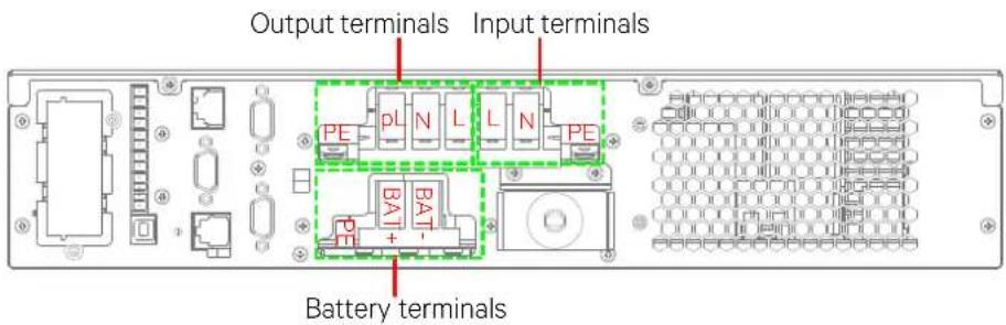
text_image
Output terminals Input terminals PE pL N L L N PE BAT + Battery terminals
Output terminals--PE: Output PE terminal; pL: Programmable output live wire terminal; N: Output neutral line terminal; L: Output live wire terminal.
Input terminals--L: Input live wire terminal; N: Input neutral line terminal; PE: Input PE terminal.
Battery terminals--BAT+: Battery positive terminal; BAT-: Battery negative terminal; PE: Battery PE terminal.
5kVA/6kVA
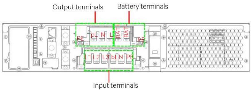
text_image
Output terminals Battery terminals L1 L2 L3 bEN PE Input terminals
Output terminals--PE: Output PE terminal; pL: Programmable output live wire terminal; N: Output neutral line terminal; L: Output live wire terminal.
Input terminals--L1\~L3: Input live wire terminals; bL: Bypass input live wire terminal; N: Input neutral line terminal; PE: Input PE terminal.
Battery terminals--BAT+: Battery positive terminal; BAT-: Battery negative terminal; PE: Battery PE terminal.
10kVA
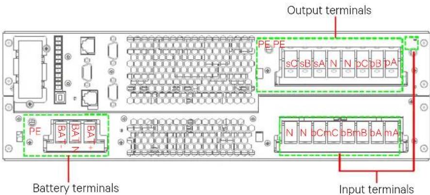
text_image
Output terminals PE PE sC sB sA N N bC bB pA Battery terminals N N bCmC bBmB bA mA Input terminals
Output terminals--Mains input terminals: sA, sB, sC; Programmable input live wire terminals: pA, pB, pC; Output PE terminal: PPEE.; Common N: N.
Input terminals--Mains input terminals: mA, mB, mC; Bypass input terminals: bA, bB, bC; Common N: N; Input PE terminal: PE.
Battery terminals--BAT+: Battery positive terminal; BAT-: Battery negative terminal; PE: Battery PE terminal.
16kVA/20kVA
Figure 2-16 Terminals layout of the I/O terminal block

After the power cables connection, the protective cover board of the I/O terminal block must be reinstalled so as to avoid electric shock.
UPS POWER CONFIGURATIONS
5kVA/6kVA UPS
- Confirm that all the external input and output switches of the UPS are disconnected.
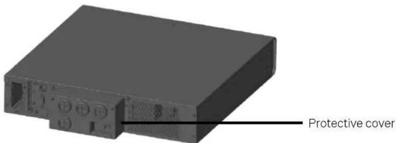
- Remove the protective cover of the I/O terminal block as shown in Figure 2-17.
- Pass the input live wire, input N line and input PE line through the cable entry holes of the junction box, and respectively connect them to the input live wire terminal (L), input N line terminal (N) and input PE terminal (PE), then fasten the fixing screws. See Figure 2-18.
text_image
Protective coverFigure 2-17 Removing protective cover
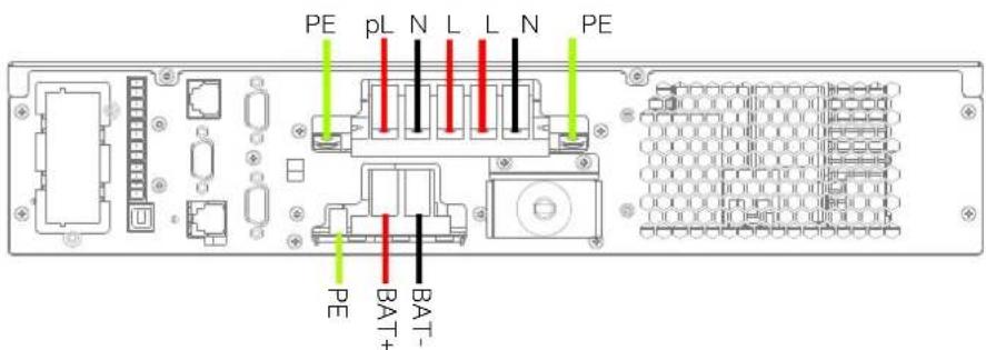
text_image
PE pL N L L N PE BAT- PE BAT-Figure 2-18 Wiring diagram
- As shown in Figure 2-18, pass the output live wire, output N line and output PE line through the cable entry holes of the junction box, and connect them to the output live wire terminal (L), output N line terminal (N) and output PE terminal (PE) respectively, then fasten the fixing screws.
If you need the programmable output to power the non-priority load, just pass the programmable output live wire through the cable hole of the junction box, and connect to the programmable output live wire terminal (pL), then fasten the fixing screws.
- As shown in Figure 2-18, pass the battery positive line, battery negative line and PE line through the cable hole of the junction box, and connect them to the battery positive terminal (BAT+), battery negative terminal (BAT-) and battery PE terminal (PE) respectively, then fasten the fixing screws.
10kVA UPS
According to user's requirements, the I/O cable connections are divided into four types: 1-in 1-out, common input configuration (factory default), 1-in 1-out, split-bypass configuration, 3-in 1-out, common input configuration, 3-in 1-out, split-bypass configuration.
Table 2-5 Shorting copper bar of 10kVA
| Bypass shorting copper bar | Drawing | |
| 1#: 4PIN copper bar | 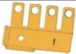 | |
| 2#: 3PIN copper bar | 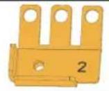 | |
| 3#: 2PIN copper bar | 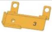 | |
The I/O cable connection procedures for the four possible types of UPS distribution configurations
1-in 1-out, common input configuration (factory default)
-
Confirm that all the external input and output switches of the UPS are disconnected.
-
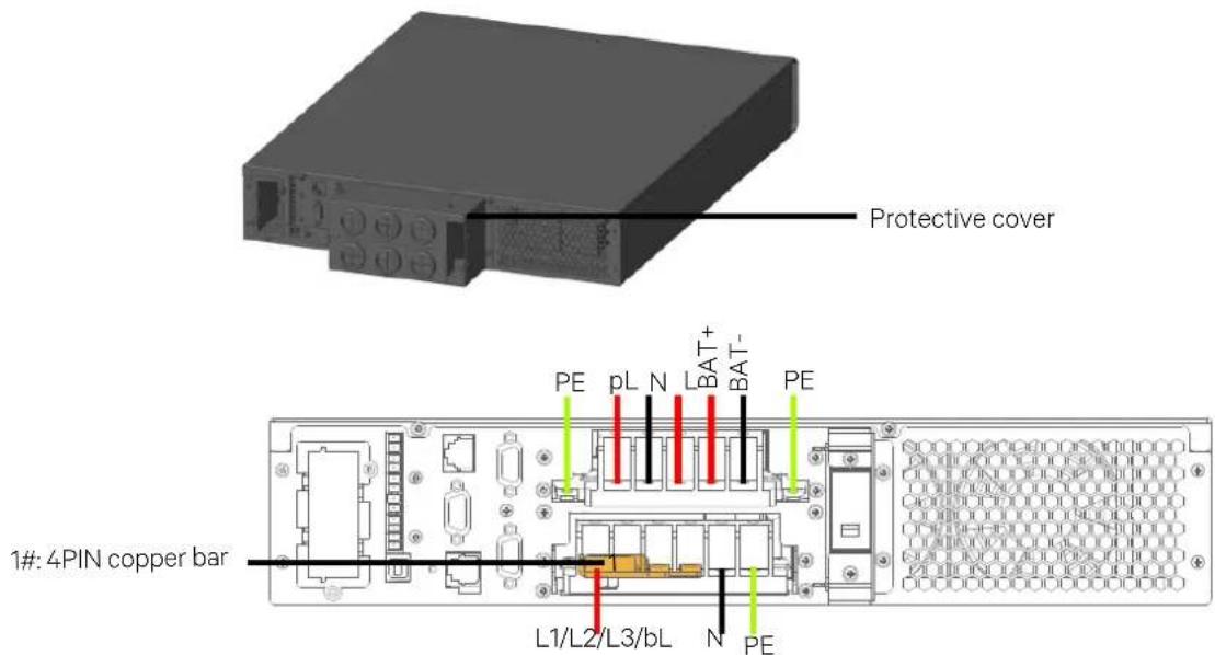
Remove the protective cover of the I/O terminal block as shown in Figure 2-19.
-
Pass the mains input live wire through the cable hole of the junction box, and connect to the shorting copper bar 1 installed before delivery. Pass the mains input N line and input PE line through the cable holes, and connect them to the input N line terminal (N), input PE terminal (PE) respectively, then fasten the fixing screws. See Figure 2-19.
text_image
Protective cover 1#: 4PIN copper bar L1/L2/L3/bL N PE PE pL N BAT+ BAT- PEFigure 2-19 Wiring diagram (1-in 1-out, common input configuration)
- As shown in Figure 2-19, pass the output live wire, output N line and output PE line through the cable entry holes of the junction box, and connect them to the output live wire terminal (L), output N line terminal (N) and output PE terminal (PE) respectively, then fasten the fixing screws.
If you need the programmable output to power the non-priority load, just pass the programmable output live wire through the cable hole of the junction box, and connect to the programmable output live wire terminal (pL), then fasten the fixing screws.
1-in 1-out, split-bypass configuration
- Confirm that all the external input and output switches of the UPS are disconnected.
- Remove the protective cover of the I/O terminal block as shown in Figure 2-19.
- Remove the shorting copper bar 1 installed before delivery.
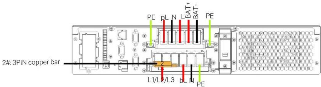
- Connect the shorting copper bar 2 to the input live wire terminal (L1, L2, L3), and fasten the fixing screws.
Pass the mains input live wire through the cable hole of the junction box and connect to the terminal block. Pass the bypass input live wire, mains input N line and input PE line through the cable holes, and connect them to the bypass input live wire terminal (bL), input N line terminal (N), input PE terminal (PE) respectively, then fasten the fixing screws. See Figure 2-20.
If you need the programmable output to power the non-priority load, just pass the programmable output live wire through the cable hole of the junction box, and connect to the programmable output live wire terminal (pL), then fasten the fixing screws.
text_image
2#: 3PIN copper bar PE pL N L BAT+ BAT- 2 L1/L2/L3 bL N PEFigure 2-20 Wiring diagram (1-in 1-out, split-bypass configuration)
- As shown in Figure 2-20, pass the output live wire, output N line and output PE line through the cable entry holes of the junction box, and connect them to the output live wire terminal (L), output N line terminal (N) and output PE terminal (PE) respectively, then fasten the fixing screws.
3-in 1-out, common input configuration

The factory default of the UPS is 1-in 1-out, common input configuration. If you need to change the power distribution mode to 3-in 1-out, strictly follow the steps described below. Continue the input and output power cable connection and power-on commissioning after confirming that the change has been successful.
- Confirm that all the external input and output switches of the UPS are disconnected.
- Remove the protective cover of the I/O terminal block as shown in Figure 2-19.
- Remove the shorting copper bar 1 installed before delivery.
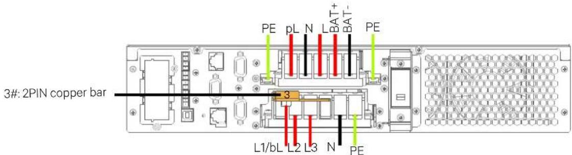
- Connect the shorting copper bar 3 to the input live wire terminal (L1), bypass input live wire terminal (bL), and fasten the fixing screws.
Pass the mains input three-phase live wire through the cable hole of the junction box, and connect the live wire L1 to the shorting copper bar 3, live wires L2 and L3 to the terminals L2 and L3 shown in Figure 2-21. Pass the mains input N line and input PE line through the cable holes, and connect them to the input N line terminal (N), input PE terminal (PE) respectively, then fasten the fixing screws. See Figure 2-21.
text_image
PE pL N BAT+ BAT- 3#: 2PIN copper bar 3 L1/bL L2 L3 N PEFigure 2-21 Wiring diagram (3-in 1-out, common input configuration)
- As shown in Figure 2-21, pass the output live wire, output N line and output PE line through the cable entry holes of the junction box, and connect them to the output live wire terminal (L), output N line terminal (N) and output PE terminal (PE) respectively, then fasten the fixing screws.
If you need the programmable output to power the non-priority load, just pass the programmable output live wire through the cable hole of the junction box, and connect to the programmable output live wire terminal (pL), then fasten the fixing screws.
3-in 1-out, split-bypass configuration
-
Confirm that all the external input and output switches of the UPS are disconnected.
-
Remove the protective cover of the I/O terminal block as shown in Figure 2-19.
-
Remove the shorting copper bar 1 installed before delivery.
-
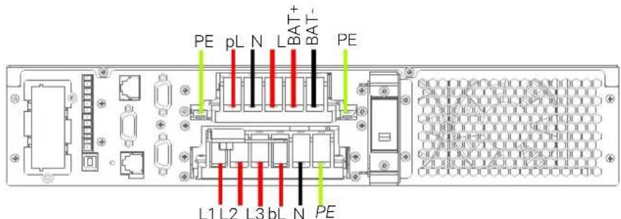
Pass the mains input live wire, bypass input live wire, input N line and input PE line through the cable holes of junction box, and connect them to the input live wire terminals (L1, L2, L3), bypass input live wire terminal (bL), input N line terminal (N) and input PE terminal (PE) respectively, then fasten the fixing screws. As shown in Figure 2-22.
text_image
PE pL N L BAT+ BAT- PE L1 L2 L3 bL N PEFigure 2-22 Wiring diagram (3-in 1-out, split-bypass configuration)
- As shown in Figure 2-22, pass the output live wire, output N line and output PE line through the cable entry holes of the junction box, and connect them to the output live wire terminal (L), output N line terminal (N) and output PE terminal (PE) respectively, then fasten the fixing screws.
If you need the programmable output to power the non-priority load, just pass the programmable output live wire through the cable hole of the junction box, and connect to the programmable output live wire terminal (pL), then fasten the fixing screws.

For split-bypass configuration, the bypass input terminal must be the upstream switch with 100A recommended.
16kVA/20kVA UPS
According to user's requirements, the I/O cable connections are divided into four types: 3-in 3-out, common input configuration (factory default), 3-in 3-out, split-bypass configuration, 3-in 1-out, common input configuration, 3-in 1-out, split-bypass configuration.
Table 2-6 Shorting copper bar of 16kVA\~20kVA
| Bypass shorting copper bar | Drawing |
| 1#: 2PIN copper bar | 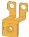 |
| 2#: 3PIN copper bar | 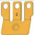 |
| 3#: 3PIN copper bar | 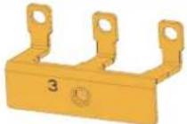 |
| 4#: 4PIN copper bar | 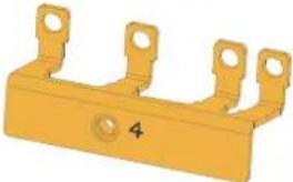 |
| 5#: 2PIN copper bar | 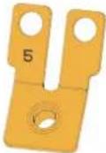 |
The I/O cable connection procedures for the four possible types of UPS distribution configurations
3-in 3-out, common input configuration
-
Connect Input terminals of mains & bypass together i.e. mA & bA, mB & bB, and mC &bC terminals respectively using three shorting copper bars 1#.
-
Connect the mains input live wires (L1, L2, L3), input N line and input PE line respectively to the I/O terminal block (mA, mB, mC, N and PE terminals) of the UPS.
-
Connect the standard output live wires (phase-A, phase-B and phase-C) respectively to the output terminals sA, sB and sC respectively. Connect the programmable output live wires (phase-A, phase-B and phase-C) respectively to the output terminals pA, pB and pC. Connect the output N line and output PE line respectively to the output terminals N and PE. As shown in Figure 2-23.
-
As shown in Figure 2-23, lead the battery positive cable, battery N cable and battery negative cable through the cable hole of the junction box, then respectively connect them to BAT+, BAT N, BAT- and PE, then fasten the fixing screws.
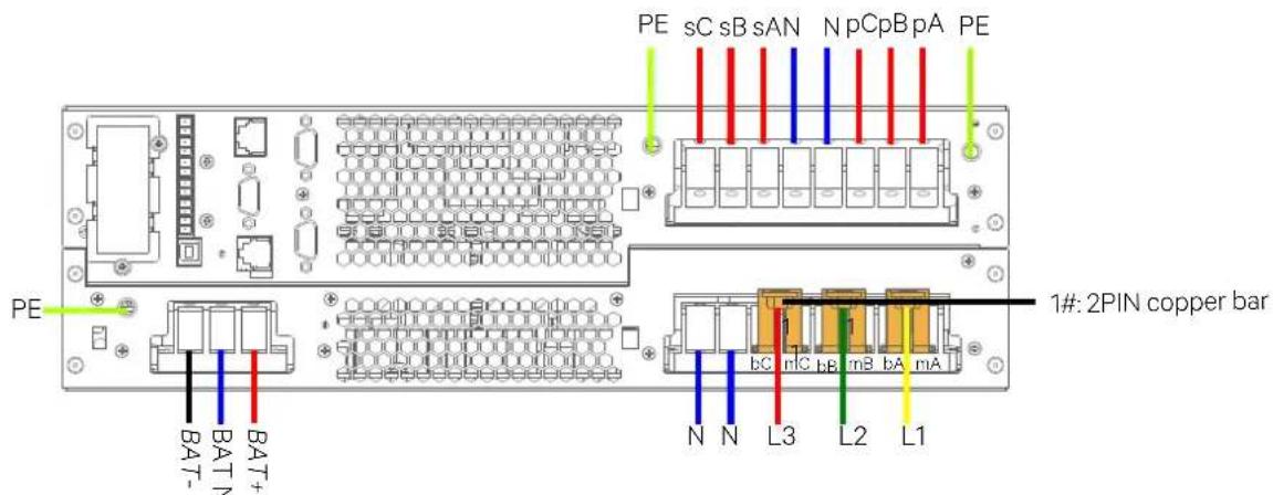
text_image
PE sC sB sAN N pCpB pA PE 1#: 2PIN copper bar N N L3 L2 L1 BAT- BAT+ BAT-Figure 2-23 Wiring diagram (3-in 3-out, common input configuration)
3-in 3-out, split-bypass configuration
-
Remove the three shorting copper bars 1#.
-
Connect the input live wires (phase-A, phase-B and phase-C), input N line and input PE line respectively to the I/O terminal block (mA, mB, mC, N and PE terminals) of the UPS. Connect the bypass input live wires (phase-A, phase-B, phase-C and N) respectively to the input terminals bA, bB, bC and N.
-
Connect the standard output live wires (phase-A, phase-B and phase-C) respectively to the output terminals sA, sB and sC. Connect the programmable output live wires (phase-A, phase-B and phase-C) respectively to the output terminals pA, pB and pC.
Connect the output N line and output PE line respectively to the output terminals N and PE. As shown in Figure 2-24.
- As shown in Figure 2-24, lead the battery positive cable, battery N cable and battery negative cable through the cable hole of the junction box, then respectively connect them to BAT+, BAT N, BAT- and PE, then fasten the fixing screws.
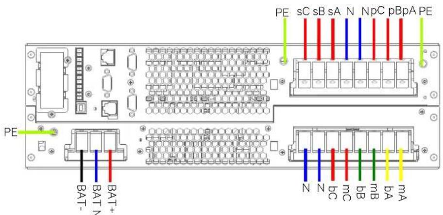
text_image
PE sC sB sA N NpC pBpA PE BAT- BAT+ N N bC mC bB mb BA mAFigure 2-24 Wiring diagram (3-in 3-out, split-bypass configuration)
3-in 1-out, common input configuration
- Remove the three shorting copper bars 1 installed before delivery.
- Use the shorting copper bar 4 to connect the input terminals (bA, bB, bC, mA), use the shorting copper bar 1 to connect the input terminal N. Use the shorting copper bar 2 to connect the output terminals (sA, sB, sC, pA, pB, pC), and use the shorting copper bar 5 to connect the output terminal N.
- Connect the mains input phase-A live wire (L1) to the shorting copper bar 4 (bA, bB, bC, mA), connect the input N line to the shorting copper bar 1 (N), and connect the input phase-B and phase-C live wires (L2, L3) to the input terminals (mB, mC), then connect the input PE line to the PE terminal.
- Connect the standard output live wire (sL) to the shorting copper bar 2 (sA, sB and sC). Connect the programmable output live wire (pL) to the shorting copper bar 2 (pA, pB and pC). Connect the output N line and output PE line respectively to the output terminals N and PE. As shown in Figure 2-25.
- As shown in Figure 2-25, lead the battery positive cable, battery N cable and battery negative cable through the cable hole of the junction box, then respectively connect them to BAT+, BAT N, BAT- and PE, then fasten the fixing screws.
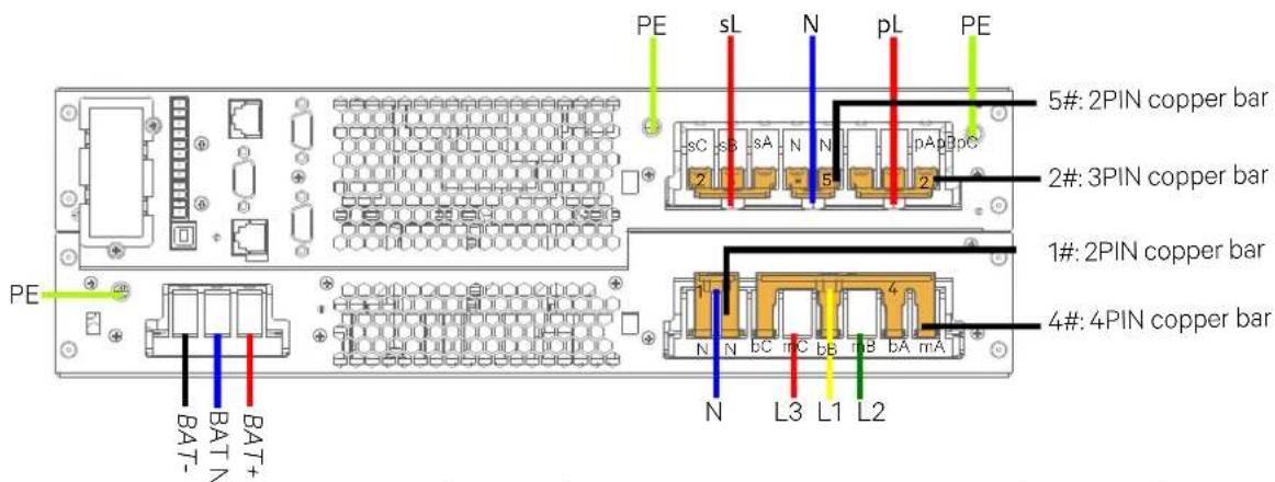
text_image
PE sL N pL PE 5#: 2PIN copper bar 2#: 3PIN copper bar 1#: 2PIN copper bar 4#: 4PIN copper bar N L3 L1 L2 BAT- BAT+ BA-Figure 2-25 Wiring diagram (3-in 1-out, common input configuration)
3-in 1-out, split-bypass configuration
- Remove the three shorting copper bars 1 installed before delivery.
- Use the shorting copper bar 3 to connect the input terminals (bA, bB, bC), use the shorting copper bar 1 to connect the input terminal N. Use the shorting copper bar 2 to connect the output terminals (sA, sB, sC, pA, pB, pC), and use the shorting copper bar 5 to connect the output terminal N.
- Connect the bypass input live wire (bL) to the shorting copper bar 3 (bA, bB, bC), connect the bypass input N line to the shorting copper bar 1 (N), and connect the mains input live wires (L1, L2, L3) to the input terminals (mA, mB, mC), next connect the mains input N line to shorting copper bar 1, then connect the input PE line to the PE terminal.
- Connect the standard output live wire (sL) to the shorting copper bar 2 (sA, sB and sC). Connect the programmable output live wire (pL) to the shorting copper bar 2 (pA, pB and pC). Connect the output N line and output PE line respectively to the output terminals N and PE. As shown in Figure 2-26.
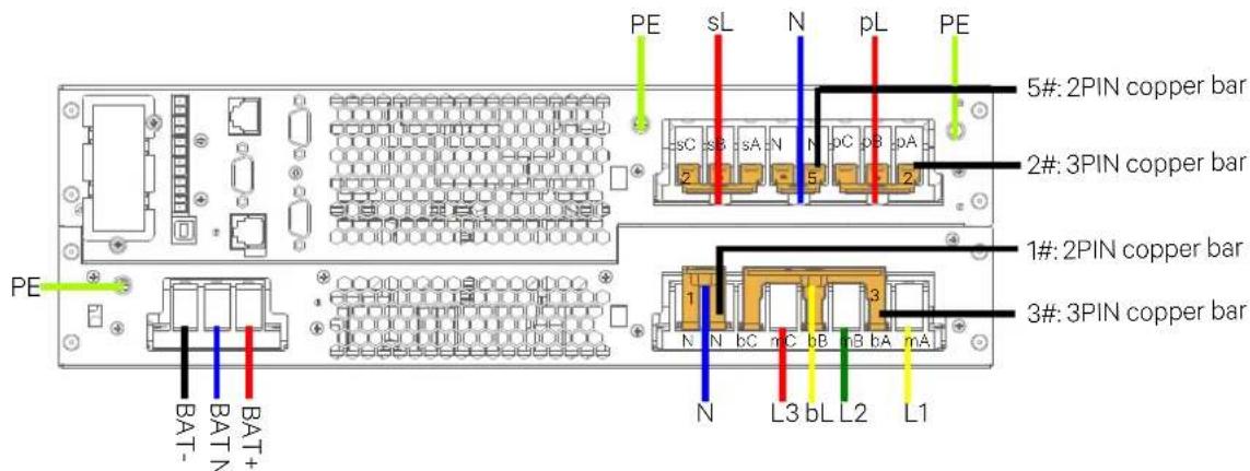
text_image
PE sL N pL PE 5#: 2PIN copper bar 2#: 3PIN copper bar 1#: 2PIN copper bar 3#: 3PIN copper bar N bC nC bB nB bA mA L3 bL L2 L1 BAT- BAT+ BAT-Figure 2-26 Wiring diagram (3-in 1-out, split-bypass configuration)
- As shown in Figure 2-26, lead the battery positive cable, battery N cable and battery negative cable through the cable hole of the junction box, then respectively connect them to BAT+, BAT N, BAT- and PE, then fasten the fixing screws.

The following wiring will change the power distribution mode, please strictly observe the procedures below.
2.6.2 Connecting Battery Cables
Notes
- Before connecting the battery cables, confirm that the actual battery cell number and capacity are consistent with the parameter settings on the LCD menus.
- It is prohibited to reverse the polarity of the battery cables.
- Before replacing the battery module and connecting the battery cables, disconnect the DC battery MCB, power off the UPS completely, and conduct isolation protection on the terminals.
- It is recommended that the battery cable should not be longer than three meters. Otherwise, the UPS cannot operate normally.
Installing battery insulating plate
The battery terminals need insulating plates to ensure sufficient insulation distance between the battery external cables connection and to avoid the faults like arcing, short circuit occurrence.
Installation steps are as follows (taking 16kVA/20kVA model for example):
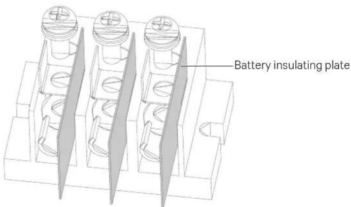
text_image
Battery insulating plateFigure 2-27 Installing battery insulating plates (16kVA/20kVA)
- First crimp the user external cable on the battery terminals, Figure 2-27 shows the OT terminals.
- Crimp the battery insulating plates, and use the screws to fasten the OT terminals and insulating plates together onto the terminal block.

Note: The installation sequence of the OT terminals and insulating plates must be strictly observed, otherwise the user external cables connection will be separated.
Installing battery
- Before installation, you must inspect the appearance and accessories of the battery, and carefully read this manual and the user manual provided by the battery manufacturer.
- Maintain at least 10mm clearances between the front, rear, side panels of the battery and the wall or adjacent equipment to keep well-ventilated.
- Maintain some clearances between the top of the battery and the upper baffle to facilitate monitoring and maintenance of the battery.
- Install the batteries from the bottom to the top to prevent too high center of gravity. Place the battery well to avoid shaking and impact.
Connecting external battery string
-
5kVA/6kVA/10kVA: The default battery number of the UPS is 16-block. The external battery string connection principle diagram is shown in Figure 2-28.
-
16kVA/20kVA: The default battery number of the UPS is 32-block (16-block for positive and 16-block for negative). The external battery string connection principle diagram is shown in Figure 2-29.

-
As shown in Figure 2-28 and Figure 2-29, one DC battery MCB must be added between the battery strings and the UPS.
-
The voltage of the battery string is DC high voltage, the capacity of the MCB and output cables is listed in Table 2-4.
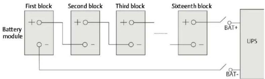
flowchart
graph LR
    A["First block"] --> B["Second block"]
    B --> C["Third block"]
    C --> D["Sixteenth block"]
    D --> E["UPS"]
    F["Battery module"] --> A
    G["BAT+"] --> D
    H["BAT-"] --> E
Figure 2-28 Battery string connection principle diagram
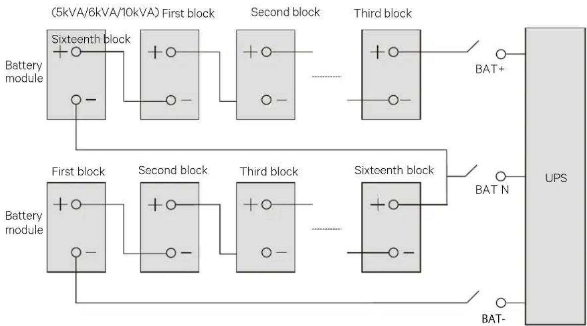
flowchart
graph LR
    subgraph_Top_Bus[" (5kVA/6kVA/10kVA) First block "]
        A1["Sixteenth block"] --> B1["+"]
        B1 --> C1["Second block"]
        C1 --> D1["Third block"]
        D1 --> E1["UPS"]
        A2["Battery module"] --> B2["+"]
        B2 --> C2["Second block"]
        C2 --> D2["Third block"]
        D2 --> E2["Sixteenth block"]
        F1["First block"] --> G1["+"]
        G1 --> H1["Second block"]
        H1 --> I1["Third block"]
        I1 --> J1["Sixteenth block"]
        K1["Battery module"] --> L1["+"]
        L1 --> M1["Second block"]
        M1 --> N1["Third block"]
        N1 --> O1["Sixteenth block"]
        P1["Battery module"] --> Q1["+"]
        Q1 --> R1["Second block"]
        R1 --> S1["Third block"]
        S1 --> T1["Sixteenth block"]
        U["Battery module"] --> V1["+"]
        V1 --> W1["Second block"]
        W1 --> X1["Third block"]
        X1 --> Y1["Sixteenth block"]
        Z["Battery module"] --> AA["+"]
        AA --> AB["Second block"]
        AB --> AC["Third block"]
        AC --> AD["Sixteenth block"]
        AE["Battery module"] --> AF["+"]
        AF --> AG["Second block"]
        AG --> AH["Third block"]
        AH --> AI["Sixteenth block"]
        AJ["Battery module"] --> AK["+"]
        AK --> AL["Second block"]
        AL --> AM["Third block"]
        AM --> AN["Sixteenth block"]
        AO["Battery module"] --> AP["+"]
        AP --> AQ["Second block"]
        AQ --> AR["Third block"]
        AR --> AS["Sixteenth block"]
        AT["Battery module"] --> AU["+"]
        AU --> AV["Second block"]
        AV --> AW["Third block"]
        AW --> AX["Sixteenth block"]
        AY["Battery module"] --> AZ["+"]
        AZ --> BA["Second block"]
        BA --> BB["Third block"]
        BB --> BC["Sixteenth block"]
        BD["Battery module"] --> BE["+"]
        BE --> BF["Second block"]
        BF --> BG["Third block"]
        BG --> BH["Sixteenth block"]
        BI["Battery module"] --> BJ["+"]
        BJ --> BK["Second block"]
        BK --> BL["Third block"]
        BL --> BM["Sixteenth block"]
        BN["Battery module"] --> BO["+"]
        BO --> BP["Second block"]
        BP --> BQ["Third block"]
        BQ --> BR["Sixteenth block"]
        BS["Battery module"] --> BT["+"]
        BT --> BU["Second block"]
        BU --> BV["Third block"]
        BV --> BW["Sixteenth block"]
        BX["Battery module"] --> BY["+"]
        BY --> BZ["Second block"]
        BZ --> CA["Third block"]
        CA --> CB["Sixteenth block"]
        CC["Battery module"] --> CD["+"]
        CD --> CE["Second block"]
        CE --> CF["Third block"]
        CF --> CG["Sixteenth block"]
    end
    subgraph Bottom_Lower
        H1["BAT+"] --> O1
        H2["BAT N"] --> O2
        H3["BAT-"] --> O3
    end
Figure 2-29 Battery string connection principle diagram (16kVA/20kVA)
Connecting battery module cables
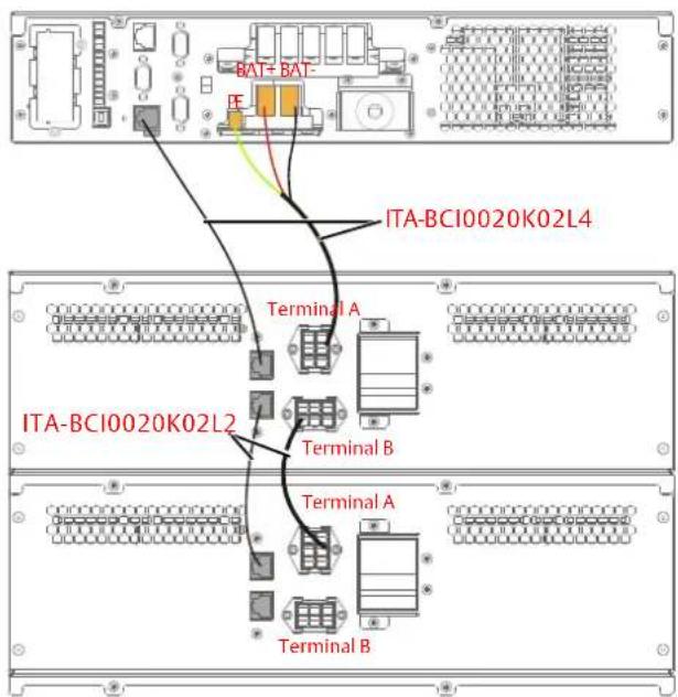
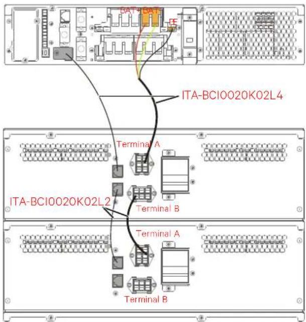
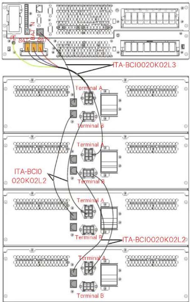
As shown in Figure 2-30, when there are several battery modules are connected, choose the cable ITA-BCI0020K02L2. The terminal A of the cable is connected to the terminal A of the first group of battery module, and the terminal B is connected to the terminal B of the second group of the battery module.
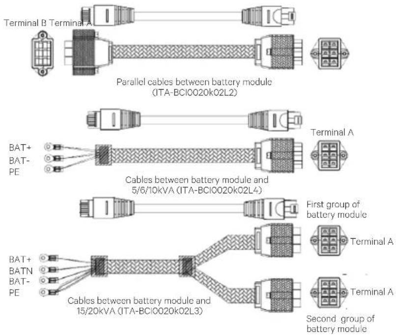
text_image
Terminal B Terminal A Parallel cables between battery module (ITA-BCI0020k02L2) BAT+ BAT- PE Cables between battery module and 5/6/10kVA (ITA-BCI0020k02L4) First group of battery module BAT+ BATN BAT- PE Cables between battery module and 15/20kVA (ITA-BCI0020k02L3) Second group of battery moduleFigure 2-30 Cables between UPS and battery modules (unit: mm)
The cable connections between the battery module and 5kVA \~ 20kVA UPS are shown in Figure 2-31.
text_image
BAT+BAT- FE ITA-BCI0020K02L4 Terminal A ITA-BCI0020K02L2 Terminal B Terminal A Terminal BWiring diagram between 5kVA/6kVA UPS and two battery modules
text_image
BAT4 BAT FE ITA-BCI0020K02L4 Terminal A ITA-BCI0020K02L2 Terminal B Terminal A Terminal BWiring diagram between 10kVA UPS and two battery modules
text_image
ITA-BCI0020K02L3 Terminal A Terminal B ITA-BCI0 O20K02L2 Terminal A Terminal B ITA-BCI0020K02L2 Terminal A Terminal BWiring diagram between 16kVA/20kVA UPS and two battery modules
Figure 2-31 Cable connection diagram between the battery module and UPS
2.7 Single UPS Commissioning
2.7.1 Check Before Start-Up
- Check and confirm that the power distribution mode of the UPS and the POD (if configured) is correct, that the connection of the power cables and signal cables is correct and that there is no short circuit.
- Check that the battery installation and the cable connection are correct, that the positive pole and the negative pole of the battery are correct.
- Measure and confirm that the mains voltage and frequency are normal.
- The output terminals of the UPS and the POD (if configured) are energized upon the startup. If the load is connected with the output terminals, ensure that the power to the load is safe.
2.7.2 Start-up Interface
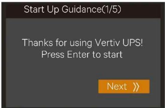
If the system is first start-up, only mains input mode can be used, and the LCD screen will display the start-up interface as shown in Figure 2-32.
text_image
Start Up Guidance(1/5) Thanks for using Vertiv UPS! Press Enter to start Next >>Figure 2-32 Start-up interface
2.7.3 Normal Mode Start-Up
- Close the external output MCB and input MCB of the UPS one by one. If the single POD is selected to connect with the UPS, close the input MCB, bypass MCB and output MCB of the POD.

After closing the UPS external output MCB or the POD output MCB, the output terminal block of the UPS, output terminal block of the POD and power distribution end of the load will be live, pay attention to personal safety to avoid electric shock. Note whether it is safe to feed power to the load.
-
The rectifier runs in normal state for about 30 seconds, the start-up of the rectifier is finished.
-
Finish and check the parameter settings of the single UPS.
a) At main menu screen, press the ▲ or ▼ key to select 'Settings', and press the ▲ key to enter the interface shown in Figure 2-33.
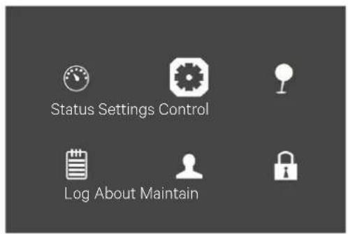
text_image
Status Settings Control Log About MaintainFigure 2-33 Main menu screen
b) Press the ▲ or ▼ key to select and set corresponding parameters (taking 'Output' as an example) as shown in Figure 2-34.
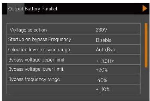
text_image
Output Battery Parallel Voltage selection 230V Startup on bypass Frequency Disable selection Inverter sync range Auto Byp... Bypass voltage upper limit +3.0Hz Bypass voltage lower limit +20% Bypass frequency range -40% +10%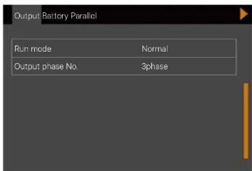
text_image
Output Battery Parallel Run mode Normal Output phase No. 3phaseFigure 2-34 Output interface
- After setting corresponding parameters, press the power button for two seconds, and the LCD prompts a dialogue box shown in Figure 2-35.
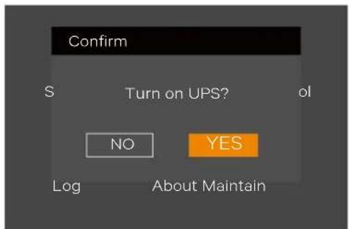
text_image
Confirm S Turn on UPS? ol NO YES Log About MaintainFigure 2-35 Turning on UPS
After selecting 'YES', the run indicator (green) blinks, the inverter starts, and the run indicator turns ON.
-
Measure whether the inverter output voltage is normal.
-
If the battery is not connected, the alarm indicator is yellow. If the battery is connected, the alarm indicator turns off.
2.7.4 Battery Mode Start-Up
-
Close the battery MCB, and press the power button on the UPS front panel for two seconds, the LCD displays the startup screen. The alarm indicator will be yellow and the buzzer will continuously beep after the rectifier finishes the startup.
-
Press the power button for two seconds, the LCD prompts a dialogue box shown in Figure 2-36.
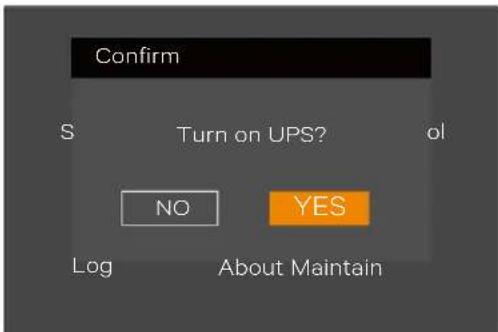
text_image
Confirm S Turn on UPS? ol NO YES Log About MaintainFigure 2-36 Turning on UPS
After selecting 'YES', the inverter starts, and the run indicator (green) is ON.
3 Parallel UPS Installation And Commissioning
This chapter introduces the features, requirements, installation and commissioning of the parallel system.
The UPS parallel system provides the user with N + X ( 2 ≤ N + X ≤ 4 , X = 0 or 1) parallel configuration, N stands for the basic parallel sets, X stands for the redundant sets.
1 + 1 parallel POD (optional) can provide safe and reliable power distribution function for the parallel system. The 1 + 1 parallel system only needs one 1 + 1 parallel POD; if N is not less than two, the external isolation will be required for the parallel system.
3.1 Features
-
The software and the hardware of each UPS in parallel system are same as those of the single UPS. The basic parameters of the parallel system can be set through the LCD (Refer to 3.5.2 Parallel System Parameters Setting for details), and the detailed parameters can be set through the background software (For service engineers only). For all UPSs of the parallel system, the requirements of the parameter settings are same.
-
The parallel cables form a ring connection (Refer to 3.4.2 Connecting Parallel Cables for details) to provide reliability and redundancy for the system. The intelligent parallel logic provides the user with maximum flexibility. For example, each UPS in the parallel system can be switched off or on in random order; seamless transfer can be achieved between Normal mode and Bypass mode, and the transfer is automatically recoverable: that is, after the overload is removed, the system will automatically return to the original operation mode.
-
The total load of the parallel system can be queried through the LCD of each UPS.
3.2 Requirements
A UPS system composed of multiple parallel-connected UPSs is equivalent to a large UPS system. Nevertheless, it provides increased system reliability. To ensure equal utilization of all UPSs and compliance with relevant wiring regulations, the following requirements must be met:
-
All single UPSs must have the same capacity. The 10kVA/16kVA/20kVA UPS must be connected to the same bypass source.
-
The bypass input power (10kVA/16kVA/20kVA only) and the rectifier input power must be connected to the same neutral line input terminal.
-
If a residual current detector (RCD) is required, it must be set correctly and installed before the same neutral line input terminal, or it must monitor the protective earth current of the system. Refer to 'Warning: high leakage current' of Safety Precautions before Contents.
-
The outputs of all single UPSs must be connected to the same output bus.
-
Since the UPS parallel system is not fitted with any auxiliary contact detection devices for the output MCB or the maintenance bypass MCB of the UPS, removing the single UPS from the parallel system before maintenance and adding the single UPS into the parallel system after maintenance must be conducted strictly following the procedures mentioned in 5.2 Transfer Procedures Between Operation Modes. Failure to observe this may affect the reliability of the load power supply.
3.3 Mechanical Installation
Considering the 16kVA/20kVA rack installation of the 1 + 1 parallel system without battery module for example, the mechanical installation method of the parallel system is as follows:
-
The installation method of 1 + 1 parallel UPS is the same as that of the single UPS. Refer to 2.5. Mechanical Installation for details.
-
As shown in Figure 3-1, the UPS should be installed at the bottom; and the 1 + 1 parallel POD should be installed on the top to facilitate the cable connection and operation. The installation method of 1 + 1 parallel POD is the same as that of the UPS.
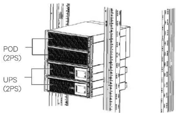
text_image
POD (2PS) UPS (2PS)Figure 3-1 1 + 1 parallel system installation (without battery module, 16kVA/20kVA)
3.4 Connecting Power Cables
Each single UPS of the parallel system needs to configure the MCB and cables respectively, refer to 2.6 Connecting Power Cables for the specification. The recommended configurations of the total power cables are listed in Table 3-1 to Table 3-4 for the parallel system.
Table 3-1 Input & output cable CSA for the 5kVA/6kVA parallel system (unit: mm², ambient temperature: 25°C)
| Parallel UPS number | 5kVA | 6kVA | ||||
| Total input cable for parallel system | Total output cable for parallel system | Grounding cable for parallel system | Total input cable for parallel system | Total output cable for parallel system | Grounding cable for parallel system | |
| 2 units | 10 | 10 | 10 | 16 | 16 | 16 |
| 3 units | 25 | 25 | 25 | 35 | 35 | 35 |
| 4 units | 35 | 35 | 35 | 50 | 50 | 50 |
Table 3-2 Input & output cable CSA for the 10kVA parallel system (unit: mm², ambient temperature: 25°C)
| Parallel UPS number | 3-in 1-out | 1-in 1-out | |||||
| Total input phase line for parallel system | Total input neutral line for parallel system | Total output cable for parallel system | Total grounding cable for parallel system | Total input cable for parallel system | Total output cable for parallel system | Total grounding cable for parallel system | |
| 2 units | 10 | 35 | 25 | 35 | 35 | 25 | 35 |
| 3 units | 10 | 70 | 50 | 70 | 70 | 50 | 70 |
| 4 units | 16 | 120 | 70 | 120 | 120 | 70 | 120 |
Table 3-3 Input & output cable CSA for the 16kVA parallel system (unit: mm ^2 , ambient temperature: 25°C)
| Parallel UPS number | 3-in 3-out | 3-in 1-out | |||||
| Single input cable for parallel system | Single output cable for parallel system | Total neutral line for parallel system | Grounding cable for parallel system | Total output cable for parallel system | Total neutral line for parallel system | Grounding cable for parallel system | |
| 2 units | 16 | 16 | 16 | 16 | 35 | 35 | 35 |
| 3 units | 25 | 25 | 25 | 25 | 50 | 50 | 50 |
| 4 units | 35 | 35 | 35 | 35 | 70 | 70 | 70 |
Table 3-4 Input & output cable CSA for the 20kVA parallel system (unit: mm², ambient temperature: 25°C)
| Parallel UPS number | 3-in 3-out | 3-in 1-out | |||||
| Single input cable for parallel system | Single output cable for parallel system | Total neutral line for parallel system | Grounding cable for parallel system | Total output cable for parallel system | Total neutral line for parallel system | Grounding cable for parallel system | |
| 2 units | 25 | 25 | 25 | 25 | 50 | 50 | 50 |
| 3 units | 35 | 35 | 35 | 35 | 70 | 70 | 70 |
| 4 units | 50 | 50 | 50 | 50 | 95 | 95 | 95 |
3.4.1 Connecting I/O Cables
The power cables of the UPS are connected to the I/O terminal block of the rear panel of the UPS, the layout of the I/O terminal block is shown in 2.6.1 Connecting I/O Cables.
Power distribution mode
There are two modes for UPS parallel power distribution: using the 1 + 1 parallel POD (optional) provided by Vertiv, external isolation.
The power distribution mode of the parallel system is the same as that of the single unit, refer to 2.6.1 Connecting I/O Cables.
1. Using parallel POD power distribution
It is recommended to use 1 + 1 parallel POD power distribution mode if you need 1 + 1 parallel system, for the installation and commissioning of different models, refer to Liebert® ITA2™ 5kVA And 6kVA UPS Power Output Distribution Unit User Manual,
Liebert® ITA2™ 10kVA UPS Power Output Distribution Unit User Manual, and Liebert® ITA2™ 16kVA And 20kVA UPS Power Output Distribution Unit User Manual.
2. External isolation for the parallel system
When the UPS number of the parallel system is more than two, use external isolation mode.
The block diagram of three UPSs parallel system is shown in Figure 3-2. Refer to Power distribution mode in
2.6.1 Connecting I/O Cables for the cable connection of each UPS. Refer to 2.6
Connecting Power Cables for the input and output MCB, the battery MCB and the cables when using the external isolation mode.
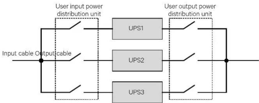
flowchart
graph LR
    A["Input cable Output cable"] --> B["User input power distribution unit"]
    B --> C["UPS1"]
    B --> D["UPS2"]
    B --> E["UPS3"]
    C --> F["User output power distribution unit"]
    D --> F
    E --> F
Figure 3-2 Block diagram of three UPSs parallel system

Configure each UPS with external input MCB and external output MCB when carrying out the power distribution for the parallel system, as shown in Figure 3-2.

After connecting power cables, the protective cover of the I/O terminal block must be reinstalled to avoid electric shock.
Changing power distribution mode (16kVA/20kVA only)
The 16kVA/20kVA model is compatible with 3-in 3-out/3-in 1-out, factory default: 3-in 3-out.
If you need to change the mode from 3-in 3-out to 3-in 1-out or from 3-in 1-out to 3-in 3-out, carry out the parallel connection after changing the single system to the needed system (Refer to 2.6.1 Connecting I/O Cables for the changing method).
3.4.2 Connecting Parallel Cables
The parallel system provides parallel cable option. The parallel cables form a ring connection through the parallel ports on the rear panel of the UPS. Taking 16kVA/20kVA model for example, the cable connection schematic diagram of 3 + 1 parallel system is shown in Figure 3-3.
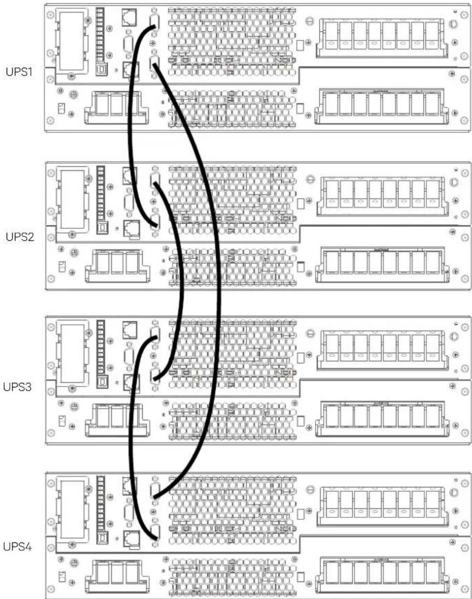
text_image
UPS1 UPS2 UPS3 UPS4Figure 3-3 Cable connection schematic diagram of 3 + 1 parallel system (16kVA/20kVA)

- The Vertiv parallel cables must be used for the parallel system.
- If the parallel communication fault occurs during the parallel commissioning or operation, just shut off the system and check whether the connection of the parallel cables is correct.
- During parallel system operation, do not unplug the parallel cables to avoid system damage risk.
3.4.3 Connecting Battery Cables
In the parallel system, the 16kVA/20kVA UPS can support either Distributed battery System (Independent battery systems on each UPS unit) or Centralized battery system (Shared battery system by UPS units). The 5kVA/6kVA/10kVA UPS can only support distributed battery arrangement.

Each UPS should be equipped with an independent battery MCB. Refer to Table 2-4 for selection of the battery MCB.
In Distributed Battery System
When each UPS of the parallel system uses the independent battery string, the battery cables connection of each UPS in the parallel system is the same as that of the single UPS, refer to 2.6.2 section for Battery cable connections. The schematic diagram of battery strings in 1 + 1 parallel system with independent battery strings is shown in Figure 3-4. Refer to 2.6 section for connecting power cables to configure an MCB.

Ensure that the LCD settings are correct when using the battery strings independently for the parallel system, refer to 3.5.2 Parallel System Parameters Settings for details.
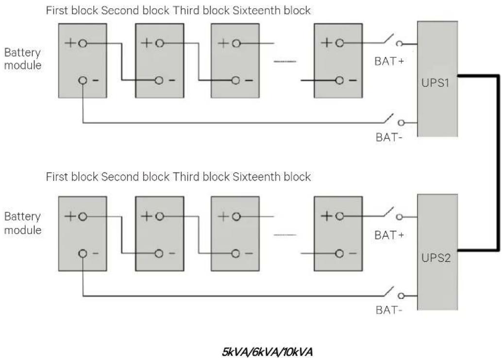
flowchart
graph TD
    subgraph First_block
        A1["+○"] --> B1["○-"]
        A2["+○"] --> B2["○-"]
        A3["+○"] --> B3["○-"]
        B1 --> C1["BAT+"]
        B2 --> C2["BAT-"]
        B3 --> D1["BAT+"]
        B4["⊕"] --> C3["BAT-"]
        C1 --> E1["UPS1"]
        C2 --> E2["UPS1"]
        C3 --> E3["UPS1"]
        C4["⊕"] --> E4["UPS1"]
        C5["⊕"] --> E5["UPS1"]
        C6["⊕"] --> E6["UPS1"]
        C7["⊕"] --> E7["UPS1"]
        C8["⊕"] --> E8["UPS1"]
        C9["⊕"] --> E9["UPS1"]
        C10["⊕"] --> E10["UPS1"]
        C11["⊕"] --> E11["UPS1"]
        C12["⊕"] --> E12["UPS1"]
        C13["⊕"] --> E13["UPS1"]
        C14["⊕"] --> E14["UPS1"]
        C15["⊕"] --> E15["UPS1"]
        C16["⊕"] --> E16["UPS1"]
        C17["⊕"] --> E17["UPS1"]
        C18["⊕"] --> E18["UPS1"]
        C19["⊕"] --> E19["UPS1"]
        C20["⊕"] --> E20["UPS1"]
        C21["⊕"] --> E21["UPS1"]
        C22["⊕"] --> E22["UPS1"]
        C23["⊕"] --> E23["UPS1"]
        C24["⊕"] --> E24["UPS1"]
        C25["⊕"] --> E25["UPS1"]
        C26["⊕"] --> E26["UPS1"]
        C27["⊕"] --> E27["UPS1"]
        C28["⊕"] --> E28["UPS1"]
        C29["⊕"] --> E29["UPS1"]
        C30["⊕"] --> E30["UPS1"]
        C31["⊕"] --> E31["UPS1"]
        C32["⊕"] --> E32["UPS1"]
        C33["⊕"] --> E33["UPS1"]
        C34["⊕"] --> E34["UPS1"]
        C35["⊕"] --> E35["UPS1"]
        C36["⊕"] --> E36["UPS1"]
        C37["⊕"] --> E37["UPS1"]
        C38["⊕"] --> E38["UPS1"]
        C39["⊕"] --> E39["UPS1"]
        C40["⊕"] --> E40["UPS1"]
        C41["⊕"] --> E41["UPS1"]
        C42["⊕"] --> E42["UPS1"]
        C43["⊕"] --> E43["UPS1"]
        C44["⊕"] --> E44["UPS1"]
        C45["⊕"] --> E45["UPS1"]
        C46["⊕"] --> E46["UPS1"]
        C47["⊕"] --> E47["UPS1"]
        C48["⊕"] --> E48["UPS1"]
        C49["⊕"] --> E49["UPS1"]
        C50["⊕"] --> E50["UPS1"]
        C51["⊕"] --> E51["UPS1"]
        C52["⊕"] --> E52["UPS1"]
        C53["⊕"] --> E53["UPS1"]
        C54["⊕"] --> E54["UPS1"]
        C55["⊕"] --> E55["UPS1"]
        C56["⊕"] --> E56["UPS1"]
        C57["⊕"] --> E57["UPS1"]
        C58["⊕"] --> E58["UPS1"]
        C59["⊕"] --> E59["UPS1"]
        C60["⊕"] --> E60["UPS1"]
        C61["⊕"] --> E61["UPS1"]
        C62["⊕"] --> E62["UPS1"]
        C63["⊕"] --> E63["UPS1"]
        C64["⊕"] --> E64["UPS1"]
        C65["⊕"] --> E65["UPS1"]
        C66["⊕"] --> E66["UPS1"]
        C67["⊕"] --> E67["UPS1"]
        C68["⊕"] --> E68["UPS1"]
        C69["⊕"] --> E69["UPS1"]
        C70["⊕"] --> E70["UPS1"]
        C71["⊕"] --> E71["UPS1"]
        C72["⊕"] --> E72["UPS1"]
        C73["⊕"] --> E73["UPS1"]
        C74["⊕"] --> E74["UPS1"]
        C75["⊕"] --> E75["UPS1"]
        C76["⊕"] --> E76["UPS1"]
        C77["⊕"] --> E77["UPS1"]
        C78["⊕"] --> E78["UPS1"]
        C79["⊕"] --> E79["UPS1"]
        C80["⊕"] --> E80["UPS1"]
        C81["⊕"] --> E81["UPS1"]
        C82["⊕"] --> E82["UPS1"]
        C83["⊕"] --> E83["UPS1"]
        C84["⊕"] --> E84["UPS1"]
        C85["⊕"] --> E85["UPS1"]
        C86["⊕"] --> E86["UPS1"]
        C87["⊕"] --> E87["UPS1"]
        C88["⊕"] --> E88["UPS1"]
        C89["⊕"] --> E89["UPS1"]
        C90["⊕"] --> E90["UPS1"]
        C91["⊕"] --> E91["UPS1"]
        C92["⊕"] --> E92["UPS1"]
        C93["⊕"] --> E93["UPS1"]
        C94["⊕"] --> E94["UPS1"]
        C95["⊕"] --> E95["UPS1"]
        C96["⊕"] --> E96["UPS1"]
        C97["⊕"] --> E97["UPS1"]
        C98["⊕"] --> E98["UPS1"]
        C99["⊕"] --> E99["UPS1"]
    end
    subgraph First_block
        A2["Battery module + ○- "] & A3["Battery module + ○- "] & A4["Battery module + ○- "]
    end
    subgraph Second_block
        A5["Battery module + ○- "] & A6["Battery module + ○- "] & A7["Battery module + ○- "]
    end
    subgraph Third_block
        A8["Battery module + ○- "] & A9["Battery module + ○- "] & A10["Battery module + ○- "]
    end
    subgraph Fourth_block
        A9["Battery module + ○- "] & A10["Battery module + ○- "] & A11["Battery module + ○- "]
    end
    subgraph Fifth_block
        A12["Battery module + ○- "] & A13["Battery module + ○- "] & A14["Battery module + ○- "]
    end
    subgraph Sixth_block
        A15["Battery module + ○- "] & A16["Battery module + ○- "] & A17["Battery module + ○- "]
    end
    subgraph Seventh_block
        A20["Battery module + ○- "] & A22["Battery module + ○- "] & A23["Battery module + ○- "]
    end
    subgraph Eighth_block
        A25["Battery module + ○- "] & A27["Battery module + ○- "] & A28["Battery module + ○- "]
    end
    subgraph Ninth_block
        A30["Battery module + ○- "] & A32["Battery module + ○- "] & A33["Battery module + ○- "]
    end
    subgraph Fourth_block
        A35["Battery module + ○- "] & A37["Battery module + ○- "] & A38["Battery module + ○- "]
    end
    subgraph Fifth_block
        A40["Battery module + ○- "] & A42["Battery module + ○- "] & A43["Battery module + ○- "]
    end
    subgraph Sixth_block
        A45["Battery module + ○- "] & A47["Battery module + ○- "] & A48["Battery module + ○- "]
    end
    subgraph Seventh_block
        A50["Battery module + ○- "] & A52["Battery module + ○- "] & A53["Battery module + ○- "]
    end
    subgraph Eighth_block
        A55["Battery module + ○- "] & A57["Battery module + ○- "] & A58["Battery module + ○- "]
    end
    subgraph Ninth_block
        A60["Battery module + ○- "] & A62["Battery module + ○- "] & A63["Battery module + ○- "]
    end
    subgraph Fourth_block
        A65["Battery module + ○- "] & A67["Battery module + ○- "] & A68["Battery module + ○- "]
    end
    subgraph Fifth_block
        A70["Battery module + ○- "] & A72["Battery module + ○- "] & A73["Battery module + ○- "]
    end
    subgraph Sixth_block
        A75["Battery module + ○- "] & A77["Battery module + ○- "] & A78["Battery module + ○- "]
    end
    subgraph Seventh_block
        A80["Battery module + ○- "] & A82["Battery module + ○- "] & A83["Battery module + ○- "]
    end
    subgraph Eighth_block
        A85["Battery module + ○- "] & A87["Battery module + ○- "] & A88["Battery module + ○- "]
    end
    subgraph Ninth_block
        A90["Battery module + ○- "] & A92["Battery module + ○- "] & A93["Battery module + ○- "]
    end
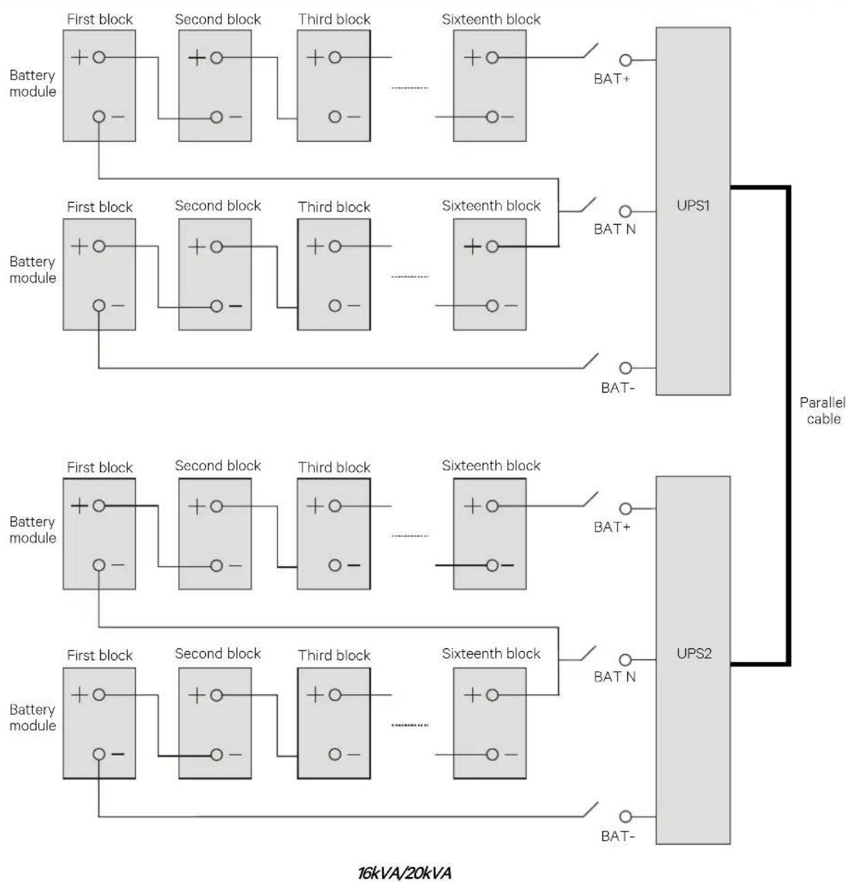
flowchart
graph TD
    subgraph_Parallel_cable["Parallel cable"]
        A1["First block"] --> B1["Second block"]
        B1 --> C1["Third block"]
        C1 --> D1["Sixteenth block"]
        D1 --> E1["UPS1"]
        F1["First block"] --> G1["Second block"]
        G1 --> H1["Third block"]
        H1 --> I1["Sixteenth block"]
        I1 --> J1["UPS2"]
        K1["First block"] --> L1["Second block"]
        L1 --> M1["Third block"]
        M1 --> N1["Sixteenth block"]
        N1 --> O1["UPS2"]
        P1["First block"] --> Q1["Second block"]
        Q1 --> R1["Third block"]
        R1 --> S1["Sixteenth block"]
        S1 --> T1["UPS2"]
        U1["First block"] --> V1["Second block"]
        V1 --> W1["Third block"]
        W1 --> X1["Sixteenth block"]
        X1 --> Y1["UPS2"]
        Z1["First block"] --> AA1["Second block"]
        AA1 --> AB1["Third block"]
        AB1 --> AC1["Sixteenth block"]
        AC1 --> AD1["UPS2"]
        AE["First block"] --> AF["Second block"]
        AF --> AG["Third block"]
        AG --> AH["Sixteenth block"]
        AH --> AI["UPS2"]
        AJ["First block"] --> AK["Second block"]
        AK --> AL["Third block"]
        AL --> AM["Sixteenth block"]
        AM --> AN["UPS2"]
    end
Figure 3-4 Connection principle diagram upon using battery strings independently
Centralized Battery System (16kVA/20kVA only)
Using the centralized battery arrangement in the parallel system can save user's investment in equipment.

-
If the battery strings (four standard battery modules, option) are shared in parallel system, the backup time of the battery module ranges from two minutes to three minutes at full load.
-
To ensure the abundant backup time of the battery, it is recommended to use the external battery cabinet with larger capacity.
Wiring
Power off the parallel system completely, disconnect the battery MCBs of all single UPSs, and then use battery cables (refer to 2.6 Connecting Power Cables for the cables and the MCBs) to connect '+', 'N', '-' and 'PE' terminals of the battery strings respectively to 'BAT+', 'BAT-', 'BAT N' and 'PE' terminals of the corresponding I/O terminal block of the UPS in the parallel system through each battery MCB, as shown in Figure 3-5.
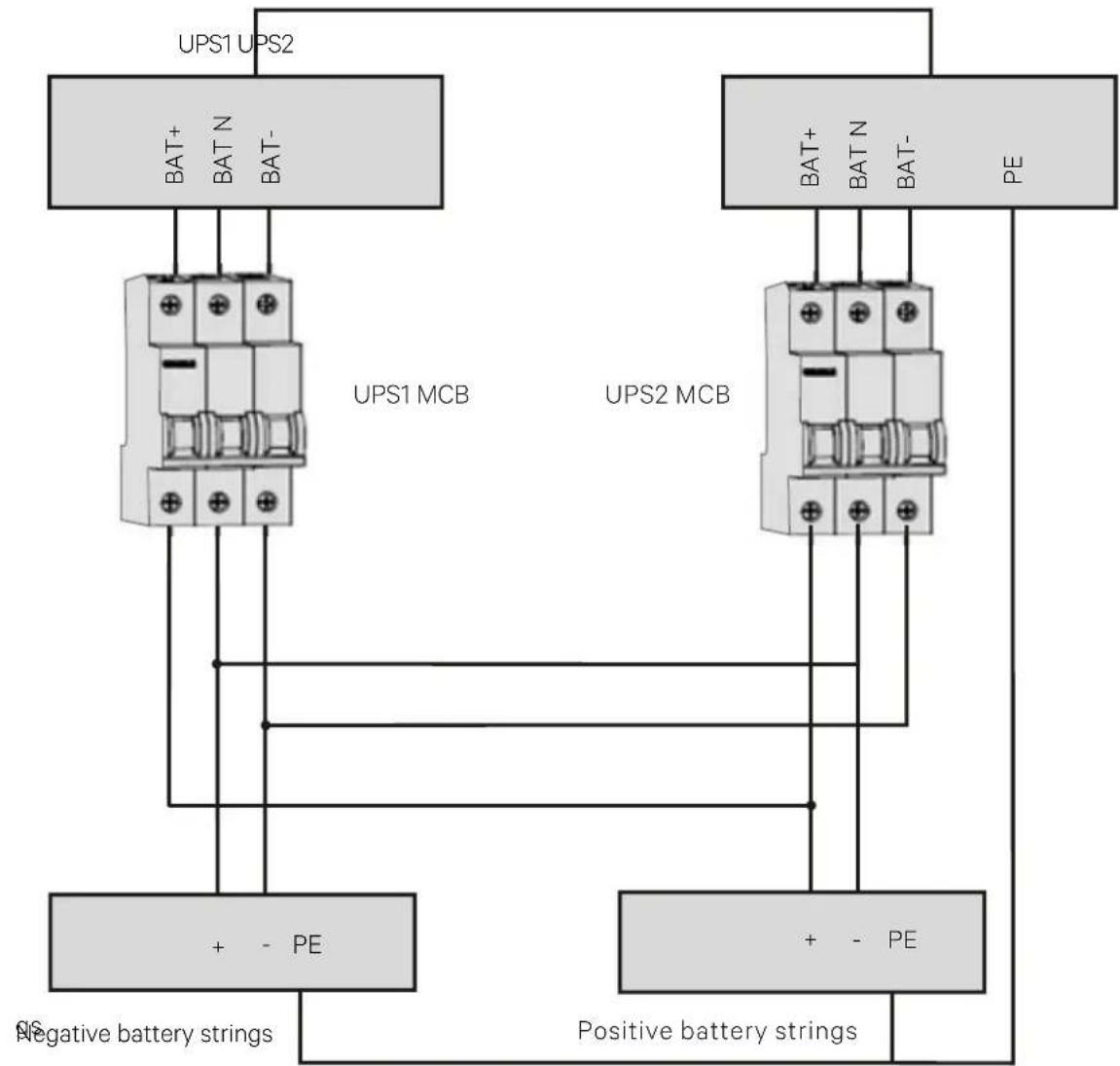
flowchart
graph TD
    A["UPS1 UPS2"] --> B["UPS1 MCB"]
    C["UPS2 MCB"] --> D["UPS2 MCB"]
    B --> E["+ - PE"]
    D --> F["+ - PE"]
    G["Negative battery strings"] --> B
    H["Positive battery strings"] --> F
Figure 3-5 Connection diagram of shared battery string in 1 + 1 parallel system
Refer to Figure 3-6 to configure the positive battery string and negative battery string.
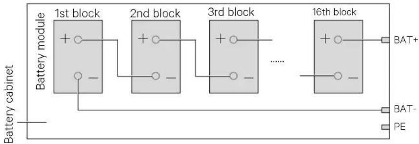
flowchart
graph LR
    A["Battery cabinet"] --> B["1st block"]
    B --> C["2nd block"]
    C --> D["3rd block"]
    D --> E["16th block"]
    E --> F["BAT+"]
    E --> G["PE"]
    style A fill:#f9f,stroke:#333
    style B fill:#ccf,stroke:#333
    style C fill:#ccf,stroke:#333
    style D fill:#ccf,stroke:#333
    style E fill:#ccf,stroke:#333
    style F fill:#fff,stroke:#333
    style G fill:#fff,stroke:#333
Figure 3-6 Internal connection diagram for positive battery string and negative battery string
Close the battery MCB of each UPS.
3.5 Commissioning Parallel System
3.5.1 Check Before Start-Up
- Check and confirm that power distribution mode of the UPS and the 1 + 1 parallel POD (if configured) is correct; that connections of the power cables and the signal cables are correct and there is no short circuit.
- Check that the battery installation and cable connection is correct and there is no short circuit, and that the positive pole and negative pole of the battery are correct. Especially when each UPS of the 16kVA/20kVA parallel system shares the battery strings, check these items carefully.
- Check all the working status of the parallel system, ensure that the phase sequence of the main, bypass (10kVA/16kVA/20kVA) and output of each UPS is correct and consistent, that the connection of the parallel cable is reliable, and that the user load is not connected during power-on.
- Measure and confirm that the mains voltage and frequency are normal.
- The output terminals of the UPS and the 1 + 1 parallel POD (if configured) are energized upon the start-up. If the load is connected with the output terminals, ensure that the power to the load is safe.

The output terminals of the UPS and the POD (if configured) will be live upon start-up. When bypass of the single UPS in the parallel system is not consistent, the system fault may occur, check and confirm the bypass before power-on.
3.5.2 Parallel System Parameters Setting
The parallel parameters for all the UPSs in the parallel system should be set. As shown in Figure 3-7.
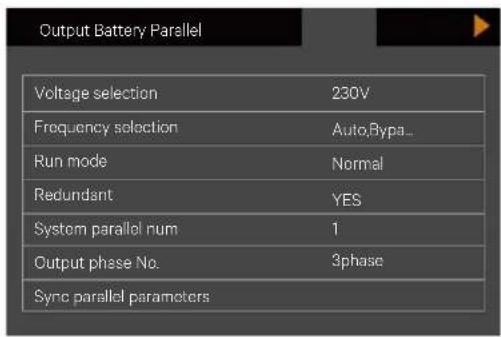
text_image
Output Battery Parallel Voltage selection 230V Frequency selection Auto,Bypa... Run mode Normal Redundant YES System parallel num 1 Output phase No. 3phase Sync parallel parametersFigure 3-7 Settings for parallel parameters
The user can change these settings according to actual needs, refer to Appendix 1 LCD Parameters Setting for details. After the change, press the last item 'Sync parallel parameters' to validate the setting.
3.5.3 Power-On Commissioning For Parallel System
- Set the parallel parameters of each UPS in the parallel system, then commission the inverter.
The specific commissioning procedures are as follows:
a) Make sure that the output MCBs of all UPSs in the parallel system are open, and then close the external input MCB of each UPS in the parallel system, the UPS is powered on at the same time. If 1 + 1 parallel POD is configured, close the corresponding input MCB and bypass MCB. At the same time, close the corresponding output MCB of the other UPS which is being tested, and make sure that the corresponding output MCB of the other UPS is open.

After the UPS external output MCB or POD output MCB is closed, the UPS output terminal block, POD output terminal block and load will be live, pay attention to personnel safety to avoid electric shock. Note whether it is safe to feed power to load.
b) The LCD displays the self check screen, and the alarm indicator (red) and run indicator (green) are ON at the same time for about five seconds.
c) After the rectifier has been in normal operation state for about 30 seconds, the rectifier start-up is finished.
d) Refer to 3.5.2 Parallel System Parameters Setting for the parallel parameters setting for each UPS. Note whether there is an alarm of 'Parallel comm. Fail', if yes, clear the fault according to Table 4-5. Carry out the following procedures if the UPS is running normally.
e) Press the power button of one UPS for 2 seconds, if 1 + 1 parallel POD is configured, press the power button of the UPS which is being tested in the parallel system, then press the Enter key to start the UPS. The run indicator (green) will blink, after 20 seconds, the inverter will start, and the run indicator will turn ON, if 1 + 1 parallel POD is configured, the other UPS will display no redundancy in parallel, ignore the prompt at the moment.
f) If the battery is not connected, the alarm indicator will be solid on, and the buzzer will beep every seconds. If the battery is connected, the alarm indicator will turn off.
g) If the UPS is working normally, press the power button for two seconds to turn off the inverter.
h) Repeat steps a) \~ step g) to power on and commission the inverter of other UPSs respectively.

Carry out the parallel commissioning after each UPS is working normally.
- After confirming that the inverter of each UPS is normal, commission the parallel system, the specific procedures are as follows:
a) Close the external output MCB and input MCB of each UPS, and all UPSs are powered on at the same time. After the start of the rectifier is finished, press the power button of one UPS for two seconds, the run indicator (green) will be on. Measure whether the inverter output voltage is normal. If the 1 + 1 parallel POD is configured, close the corresponding input MCB, bypass MCB and output MCB of the POD.
b) Start the inverter of the second UPS, check whether there is an alarm on the LCD, and confirm that the UPS parallel works normally.
c) Follow the methods to start the inverter of the third or the fourth UPS to connect the UPS into the parallel system.

-
During the parallel power-on, confirm that the external output MCB of each UPS has been closed, and that all the inverter output of the UPSs are connected parallelly.
-
During the parallel power-on, confirm that the system is working normally, and then feed power to the load, to void load power failure.
-
If the user needs to add one UPS in the parallel system, follow the commissioning procedures as mentioned below:
a) Check and confirm that the power distribution mode, each power cable and signal cable of the added UPS are well connected without short circuit. Check that the battery installation and cables connection are correct without short circuit, and that the positive and negative are correct.
b) Repeat steps a) to h) in Part 1 to complete the single unit commissioning of the added UPS. Then completely power off the UPS.
c) Ensure that the connection of power cable and signal cable is reliable.
d) For any online UPS, enter the interface shown in Figure 3-7. Set the system parallel No. from 'N' to 'N+1', then click the 'Sync parallel parameters'.
e) Close the external I/O switches of the added UPS, normally start the inverter after the rectifier start-up. Then check that the LCD has no alarm, and that the UPS parallel system works normally.

- For 1+1 parallel system, when one UPS is faulty and needs to be replaced on line, the above operation steps are available. The difference is no need to change parallel No., Simply click the 'Sync parallel parameters' for the online UPS.
- Clicking the 'Sync parallel parameters' to achieve the synchronization of the items in parallel settings interface, and the parameters will affect the parallel system. The user should manually set other parameters according to actual needs.
- When adding a single unit in the parallel system, first ensure the parallel cables connection is correct, then power on the single unit.
3.6 Installation And Commissioning For Dual Bus System (16kVA/20kVA Only)
3.6.1 Introduction
The dual bus system consists of two independent UPS systems; each UPS system consists of one or two parallel-connected single UPSs, or more parallel-connected single UPSs.
The dual bus system has high reliability, which is suitable for the load with many input terminals. For single UPS input load, you can add a Static Transfer Switch (STS, optional) to start the standard Load Bus Synchronization (LBS) system.
Place the UPSs side by side, and connect the UPSs as follows:
The dual bus system adopts the LBS system to realize the output synchronization of the two independent (or parallel) UPS systems. One is the master system, and the other is the slave system. The operation mode of the dual bus system contains master system and/or slave system running in Normal mode or Bypass mode. The schematic diagram of the LBS system built by two UPSs is shown in Figure 3-8.
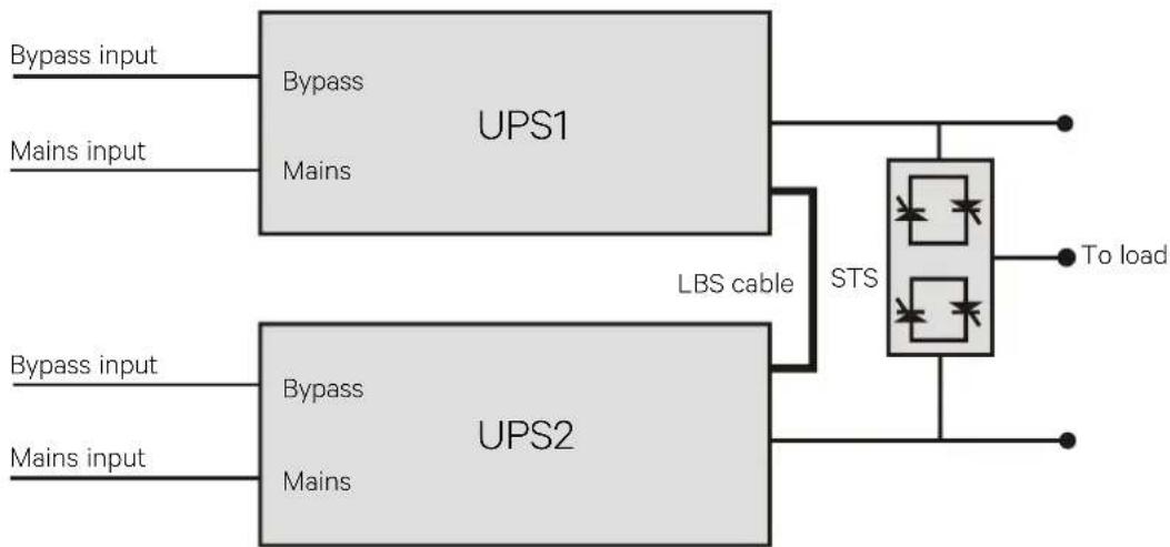
flowchart
graph LR
    A["Bypass input"] --> B["UPS1"]
    C["Mains input"] --> B
    D["Bypass input"] --> E["UPS2"]
    F["Mains input"] --> E
    B --> G["LBS cable"]
    E --> G
    G --> H["STS"]
    H --> I["To load"]
Note: UPS1 is master system while UPS2 is slave system.
Figure 3-8 LBS system schematic diagram

Refer to 3.5 Commissioning Parallel System respectively for the settings of the parallel system.
3.6.2 Installing External Protective Device
See 2.4 External Protective Device for details of installation and type selection.
3.6.3 Connecting Power Cables
In dual bus system, refer to 2.6 Connecting Power Cables and 3.4 Connecting Power Cables to select the power cables for single UPS and parallel system respectively. The bypass input power and main input power must use the input terminal of the same neutral line. If the input terminal has leakage current, the leakage current protective device should be installed before the input terminal.
3.6.4 Connecting LBS Cables

- The appearance of the LBS port is the same as the parallel port (see Figure 1-3).
- For the dual bus system formed by the parallel UPS, it is recommended to prepare two LBS cables used to connect any two parallel/LBS ports of the two parallel system, which is used for reliable connection.
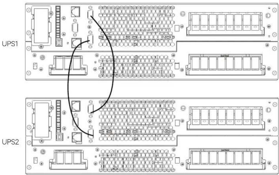
text_image
UPS1 UPS2Figure 3-9 LBS cable connection (16kVA/20kVA)
3.6.5 Setting Parameters Of LBS
The LBS parameters setting interface is shown in Figure 3-10.
Procedures for setting LBS parameters:
Through the 'Settings' -> 'System' -> 'LBS', you can set the LBS according to actual needs.
There are three items of LBS for selection: Disable, Slave, Master.
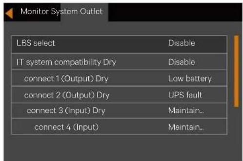
text_image
Monitor System Outlet LBS select Disable IT system compatibility Dry Disable connect 1 (Output) Dry Low battery connect 2 (Output) Dry UPS fault connect 3 (Input) Dry Maintain... connect 4 (Input) Maintain...Figure 3-10 LBS parameters setting interface
The LBS is the load synchronous system, which is used to implement the output voltage phase synchronization of the two sets of UPS system. Two sets of UPS system can be two single UPS or two sets of UPS parallel system.
You can manually set the 'Master' and 'Slave' through the LCD.
The UPS which is set to LBS master can send synchronization signal to LBS salve according to the own inverter voltage phase. After the slave receives the synchronization signal sent by the master, the slave will adjust its inverter voltage phase so as to realize the inverter voltage phase is synchronized with the master.
Through the above to realize the inverter voltage phase synchronization of two sets of UPS system, and realize the reliable transfer between the two sets of UPS output voltage and STS, then provide the reliable uninterrupted power supply to the load.
4 Operation And Display Panel
This chapter introduces the functions and use of the components on the UPS operation and display panel, and provides LCD display information, including the LCD screen types, detailed menu messages, prompt windows message and UPS alarm list.
4.1 Introduction
The operation and display panel is located on the front panel of the UPS. The operator and display panel allow the user to operate and monitor the UPS, and view the UPS parameters, UPS and battery status information and any alarm messages.
As shown in Figure 4-1, the operator and display panel include an LCD screen, menu keys, and LED indicators (run indicator and alarm indicator).
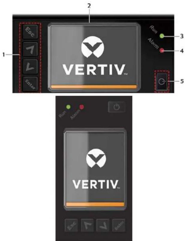
text_image
2 ESC 1 VERTIV™ Run 3 Alarm 4 Enter 5 Run Alarm VERTIV™ ESC-
Menu keys
-
Alarm indicator
-
LCD
-
Power button
-
Run indicator
Figure 4-1 Operation and display panel

The device has a gravity sensor function, thus the LCD display direction will be changed according to the device layout mode.
4.1.1 LED Indicators
The LED indicators consist of the run indicator and alarm indicator. Table 4-1 provides a description of these indicators.
Table 4-1 Description of LED indicators
| Indicator | Color | State | Meaning |
| Run indicator Green | On | UPS has output | |
| Blinking | Inverter is starting | ||
| Off | UPS has no output, inverter is starting | ||
| Alarm indicator | Yellow | On | Alarm occurs |
| Red | On | Fault occurs | |
| / | Off | No alarm, no fault | |
4.1.2 Audible Alarm (Buzzer)
The UPS operation is accompanied with the following two different kinds of audible alarms shown in Table 4-2.
Table 4-2 Description of audible alarm
| Sound | Meaning |
| Continuous beep | Sound is generated when the UPS fault appears, such as fuse or hardware failure |
| One beep every 0.5 second | Sound is generated when the UPS critical alarm appears, such as Inverter overload |
| One beep every second | Sound is generated when the UPS critical alarm appears, such as battery low voltage |
| One beep every 3.3 second | Sound is generated when the UPS general alarm appears |
4.1.3 LCD And Functional Keys
The operator and display panel include five function keys, the respective functions are described in Table 4-3.
Table 4-3 Description of control buttons
| Functional key | Silkprint | Description | |
| Confirm |  | Used to confirm or enter | |
| Up |  | Used to page up, turn left or add value, etc. | |
| Down |  | Used to page down, turn right or reduce value, etc. | |
| Escape |  | Used to back, escape, cancel or forbid operation | |
| Power |  | Used to power on, power off or transfer to Byapss mode | |
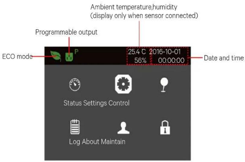
text_image
Programmable output Ambient temperature,humidity (display only when sensor connected) ECO mode 25.4 C 2016-10-01 56% 00:00:00 Date and time Status Settings Control Log About MaintainFigure 4-2 LCD screen
LCD provides you with the user-friendly interface and the 320 × 240 dot matrix image display. The user-friendly and menu-driven LCD allows you to easily browse through the UPS input, output, parameters of the load and the battery, learn about the current UPS status and alarm message, perform functional settings and control operation. The LCD also stores historical alarm records that can be retrieved for reference and diagnosis.
4.1.4 Initial Start-up Guidance
When the UPS is the initial start-up, the interface shown in Figure 4-3 will appear to guide the user to set basic parameters of the UPS.
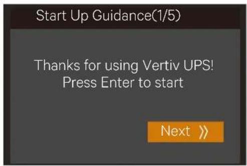
text_image
Start Up Guidance(1/5) Thanks for using Vertiv UPS! Press Enter to start Next >>Figure 4-3 Initial start-up guidance (1)
Welcome page
Click Next to start the guidance.
Language, date and time page
At this page, you can set the language, date and time you need.
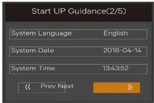
text_image
Start UP Guidance(2/5) System Language English System Date 2016-04-14 System Time 13:43:52 << Prev Next >>Figure 4-4 Initial start-up guidance (2)
Battery parameter page
At this page, you can set the battery cell number and total Ah.
For 5kVA/6kVA/10kVA model, the 'Battery series' are 12, 16, and 20 selectable. See left diagram in Figure 4-5.
For 16kVA/20kVA model, the 'Battery series' are 24, 32, and 40 selectable. See right diagram in Figure 4-5.
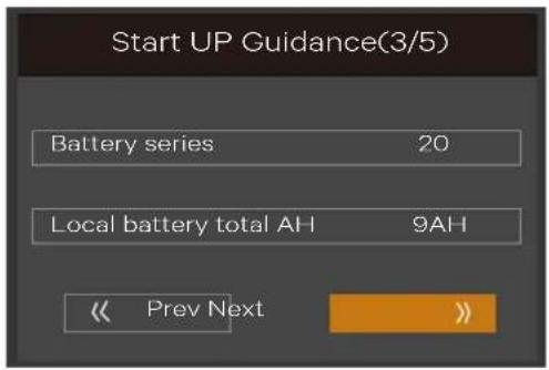
text_image
Start UP Guidance(3/5) Battery series 20 Local battery total AH 9AH << Prev Next >>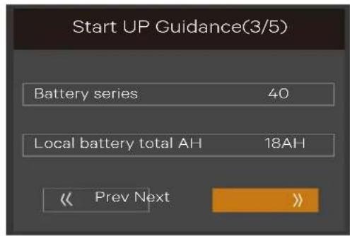
text_image
Start UP Guidance(3/5) Battery series 40 Local battery total AH 18AH << Prev Next >>Figure 4-5 Initial start-up guidance (3)
If there is an external battery module, the 'Local battery total Ah' will not appear, see Figure 4-6.
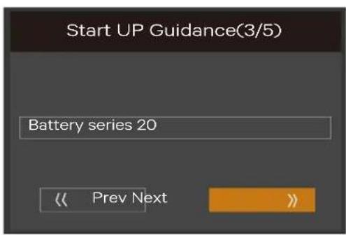
text_image
Start UP Guidance(3/5) Battery series 20 << Prev Next >>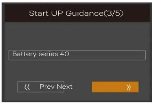
text_image
Start UP Guidance(3/5) Battery series 40 << Prev Next >>Figure 4-6 Initial start-up guidance (3)
Output page
As shown in Figure 4-8, you can set output voltage, output frequency, and output phase.
For 5kVA/6kVA/10kVA model, the 'Output phase No.' cannot be set, because the model only has single phase output. See left diagram in Figure 4-7.
For 16kVA/20kVA model, the 'Output phase No.' can be set to 'single' or '3 phases'. See right diagram in Figure 4-7.
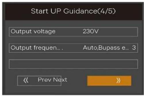
text_image
Start UP Guidance(4/5) Output voltage 230V Output frequen... . Auto,Bupass e... 3 << Prev Next >>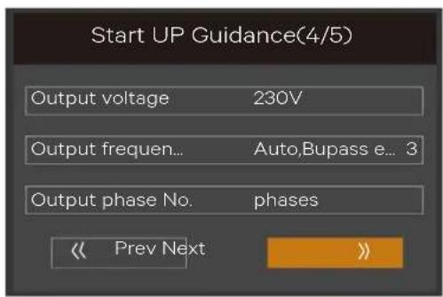
text_image
Start UP Guidance(4/5) Output voltage 230V Output frequen... Auto,Bupass e... 3 Output phase No. phases << Prev Next >>Figure 4-7 Initial start-up guidance (4)

For output page, all the settings must unplug the REPO terminal (forcible output shutdown), otherwise the interface shown in Figure 4-8 will appear.

text_image
Start UP Guidance(4/5) Notify Cannot set this on-line Please unplug REPO OK << Prev Next >>Figure 4-8 Prompt of removing REPO terminal
Finish page
For 5kVA/6kVA/10kVA model, the interface shown in Figure 4-9 will appear. Click Finish to enter the Flow page, then the user can operate the UPS normally.
Start UP Guidance(5/5)
Configuration finished Please ENTER to start
Figure 4-9 Initial start-up guidance (5)
For 16kVA/20kVA model, the interface shown in Figure 4-10 will appear. It means that the functional keys and LCD are invalid; the user cannot continue the operation. Please power off the UPS based on the prompt shown in Figure 4-10, confirm that the actual wiring method of the output terminal is the same as that of the setting method, then power on the UPS again.
After the start-up, the user can operate the UPS normally,
Start UP Guidance(5/5)
Configuration finished Please disconnect power Confirm actual connection is [3 Phase output] Then power UPS on
Figure 4-10 Initial start-up guidance (5)
4.2 LCD Menu Structure
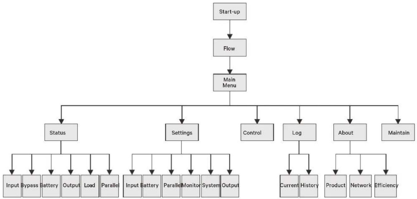
flowchart
graph TD
    A["Start-up"] --> B["Flow"]
    B --> C["Main Menu"]
    C --> D["Status"]
    C --> E["Settings"]
    C --> F["Control"]
    C --> G["Log"]
    C --> H["About"]
    C --> I["Maintain"]
    D --> J["Input"]
    D --> K["Bypass"]
    D --> L["Battery"]
    D --> M["Output"]
    D --> N["Load"]
    D --> O["Parallel"]
    E --> P["Input"]
    E --> Q["Battery"]
    E --> R["Parallel"]
    E --> S["Monitor"]
    E --> T["System"]
    E --> U["Output"]
    G --> V["Current"]
    G --> W["History"]
    H --> X["Product"]
    H --> Y["Network"]
    H --> Z["Efficiency"]
Figure 4-11 LCD menu structure
4.3 LCD Screen Types
4.3.1 Start Screen
Upon UPS start-up, the UPS executes the system self-test, and the start screen will appear and remain for about 10 seconds, as shown in Figure 4-12.

text_image
VERTIV™Figure 4-12 Start screen
4.3.2 Flow Screen
After the self-test of the UPS, the flow screen shown in Figure 4-13 will appear.
The flow screen is the total status view of the UPS, includes input, bypass, rectifier, battery, inverter and output, etc.. The working modes with color display while the invalid modes with gray display.
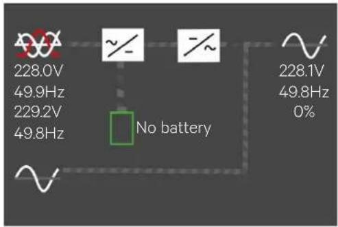
text_image
228.0V 49.9Hz 229.2V 49.8Hz No battery 228.1V 49.8Hz 0%Figure 4-13 Flow screen
At the flow page, press the key to enter the primary screen.
4.3.3 Main Menu Screen
The main menu screen is composed of six icons: Status, Settings, Control, Log, About, Maintain. As shown in Figure 4-14.
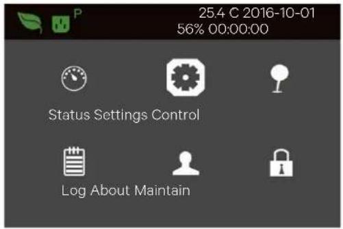
text_image
25.4 C 2016-10-01 56% 00:00:00 Status Settings Control Log About MaintainFigure 4-14 Main menu screen
At main menu screen, press the Esc key to back to the flow screen. Press the A or V key to switch the cursor to select the submenu you need, then press the Enter key to confirm it.
4.3.4 Submenu Screen
The submenu screen contains the UPS parameters and item settings.
After accessing the submenu screen, if there is a tab control, just move the cursor to the tab. At this time, you can press the ▲ or ▼ key to switch the tab. Press the Enter key to move the cursor to a certain item.
After entering the submenu screen, if there is no tab control, then the cursor will stop at a certain Item.
Press the Esc key to return to the previous screen.
For details about the submenu screen, see following pages.
Status page
The Status page contains information about the Input, Bypass, Battery, Output and Load.
See below:
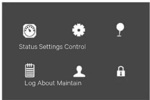
text_image
Status Settings Control Log About Maintain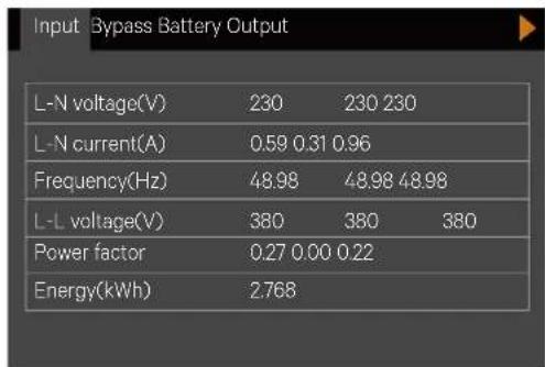
text_image
Input Bypass Battery Output L-N voltage(V) 230 230 230 L-N current(A) 0.59 0.31 0.96 Frequency(Hz) 48.98 48.98 48.98 L-L voltage(V) 380 380 380 Power factor 0.27 0.00 0.22 Energy(kWh) 2.768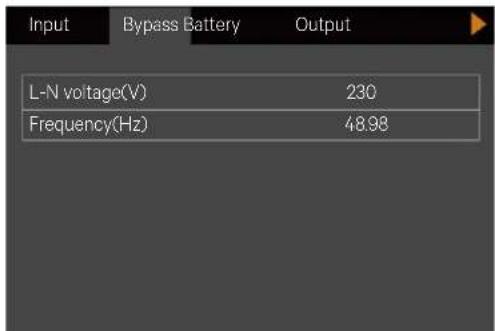
text_image
Input Bypass Battery Output L-N voltage(V) 230 Frequency(Hz) 48.98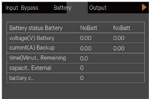
text_image
Input Bypass Battery Output Battery status Battery NoBatt NoBatt voltage(V) Battery 0.00 0.00 current(A) Backup 0.00 0.00 time(Minut... Remaining 0.0 capacit... External 0 battery c... 0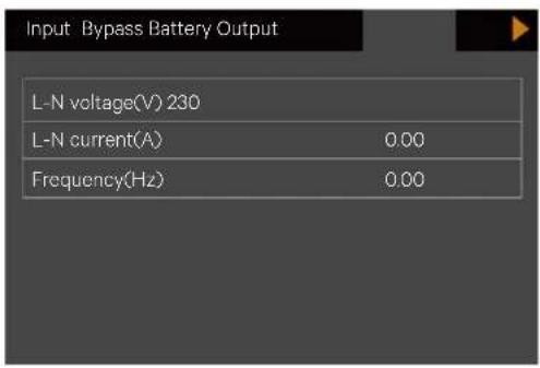
text_image
Input Bypass Battery Output L-N voltage(V) 230 L-N current(A) 0.00 Frequency(Hz) 0.00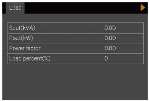
text_image
Load Sout(kVA) 0.00 Pout(kW) 0.00 Power factor 0.00 Load percent(%) 0Settings page
The Settings page contains the Output, Battery, Parallel, Monitor, System, and Outlet. For details about the parameters setting, refer to Appendix 1 LCD Parameters Setting.
See below:
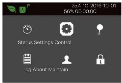
text_image
25.4 °C 2016-10-01 56% 00:00:00 Status Settings Control Log About Maintain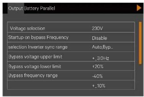
text_image
Output Battery Parallel Voltage selection 230V Startup on bypass Frequency Disable selection Inverter sync range AutoByp.. Bypass voltage upper limit +3.0Hz Bypass voltage lower limit +20% Bypass frequency range -40% +10%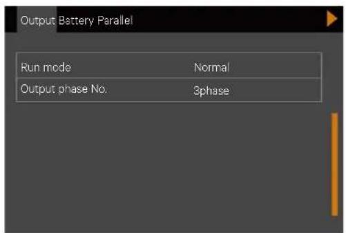
text_image
Output Battery Parallel Run mode Normal Output phase No. 3phase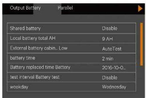
text_image
Output Battery Parallel Shared battery Disable Local battery total AH 9 AH External battery cabin.. Low AutoTest battery time 2 min Battery replaced time Battery 2016-10-0.. test interval Battery test Disable weekday Wednosday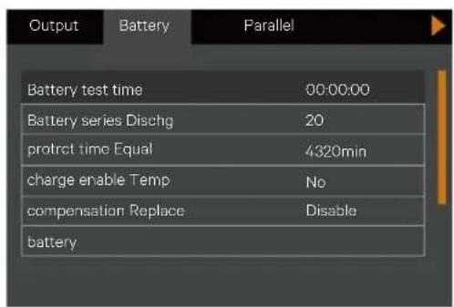
text_image
Output Battery Parallel Battery test time 00:00:00 Battery series Dischg 20 protract time Equal 4320min charge enable Temp No compensation Replace Disable battery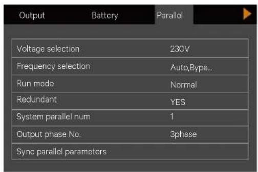
text_image
Output Battery Parallel Voltage selection 230V Frequency selection Auto, Bype... Run mode Normal Redundant YES System parallel num 1 Output phase No. 3phase Sync parallel parameters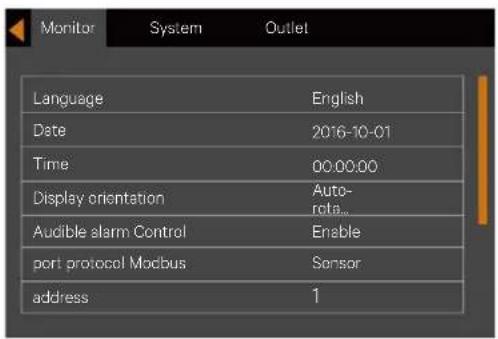
text_image
Monitor System Outlet Language English Date 2016-10-01 Time 00:00:00 Display orientation Auto- rda... Audible alarm Control Enable port protocol Modbus Sensor address 1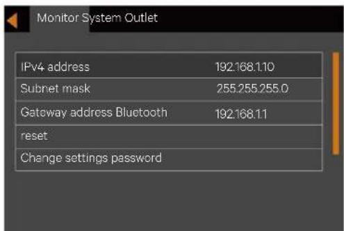
text_image
Monitor System Outlet IPv4 address 192.168.1.10 Subnet mask 255.255.255.0 Gateway address Bluetooth 192.168.1.1 reset Change settings password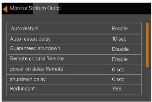
text_image
Monitor System Outlet Auto restart Enable Auto restart delay 10 sec Guaranteed shutdown Disable Remote control Remote Enable power on delay Remote 0 sec shutdown delay 0 sec Redundant YES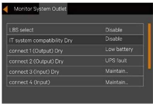
text_image
Monitor System Outlet LBS select Disable IT system compatibility Dry Disable connect 1 (Output) Dry Low battery connect 2 (Output) Dry UPS fault connect 3 (Input) Dry Maintain... connect 4 (Input) Maintain...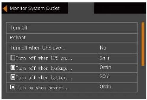
text_image
Monitor System Outlet Turn off Reboot Turn off when UPS over... No □Turn off when UPS on... 2min □Turn off when backup... 0min □Turn off when batter... 30% □Turn on when powers... 0minControl page
The Control page contains the Turn ON/OFF/to BYPASS, and Manual battery test, etc.. See below:
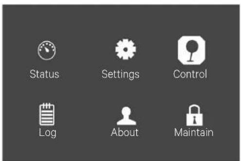
text_image
Status Settings Control Log About Maintain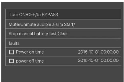
text_image
Turn ON/OFF/to BYPASS Mute/Unmute audible alarm Start/ Stop manual battery test Clear faults Power on time 2016-10-01 00:00:00 power off time 2016-10-01 00:00:00Log page
The Log page contains the Current and History. See below:
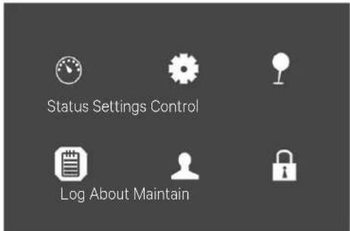
text_image
Status Settings Control Log About Maintain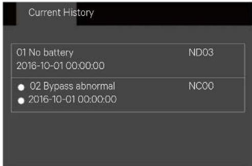
text_image
Current History 01 No battery ND03 2016-10-01 00:00:00 • 02 Bypass abnormal NC00 • 2016-10-01 00:00:00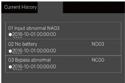
text_image
Current History 01 Input abnormal NA03 ●2016-10-01 00:00:00 02 No battery ND03 ●2016-10-01 00:00:00 03 Bypass abnormal NC00 ●2016-10-01 00:00:00About page
The About page contains the Product, Network, and Efficiency. See below:
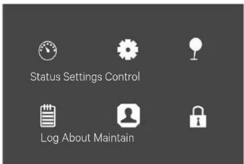
text_image
Status Settings Control Log About Maintain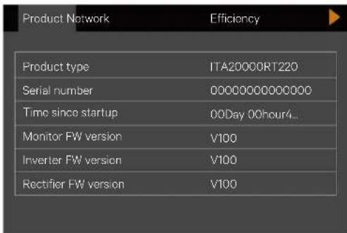
text_image
Product Network Efficiency Product type ITA20000RT220 Serial number 00000000000000 Time since startup 00Day 00hour4... Monitor FW version V100 Inverter FW version V100 Rectifier FW version V100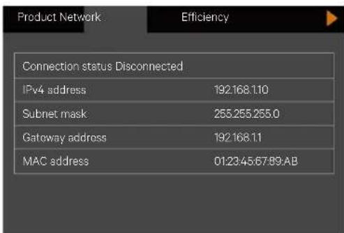
text_image
Product Network Efficiency Connection status Disconnected IPv4 address 192.168.110 Subnet mask 255.255.255.0 Gateway address 192.168.11 MAC address 01:23:45:67:89:AB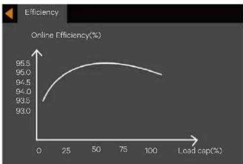
line
| Load cap(%) | Online Efficiency(%) | | ----------- | -------------------- | | 0 | 93.0 | | 25 | 94.5 | | 50 | 95.5 | | 75 | 95.0 | | 100 | 94.5 |Maintain page

The Maintain page needs correct password and for Vertiv service engineer operation only.
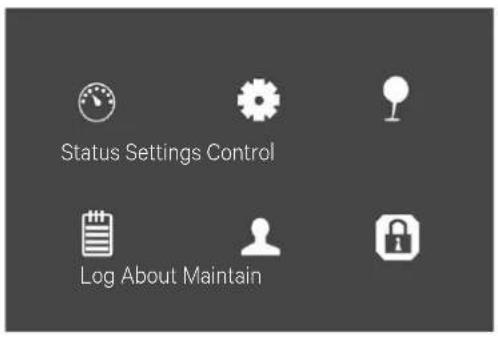
text_image
Status Settings Control Log About Maintain4.3.5 Default Screen
During the UPS operation, if there is no alarm within two minutes, the default screen shown in Figure 4-15 is displayed. At the default screen, if there is an alarm or a fault, or the user press any key, the Flow screen will appear again.

text_image
VERTIV™Figure 4-15 Default screen
4.4 Prompt Window
A prompt window is displayed during the operation of the system to alert you to certain conditions and/or to require your confirmation of a command or other operation. Table 4-4 lists the prompts and meanings.
Table 4-4 Prompts and meanings
| Prompt | Meaning |
| System setting is different, please check | When the parallel parameters are different, the prompt will appear |
| Cannot set this online, please shut down output | If the user wants to change some important settings under condition of output (output voltage, output frequency, output phase No.), the prompt will appear |
| Incorrect password, please input again | The prompt will appear when the user incorrectly input the Settings password |
| Operation failed, condition is not met | The prompt will appear when the user wants to execute a certain operation but the condition is not met |
| Password changed OK | The prompt will appear when the user successfully change the Settings password |
| Fail to change password, please try again | The prompt will appear when the user tries to change the Settings password but input two different new passwords |
| The time cannot be earlier than system time | The prompt will appear when the user set the time of 'Turn on delay' or 'Turn off delay'is earlier than the current system time |
| Turn on failed, condition is not met | When users press the power button (or execute the command of 'Turn on/Turn off/to Bypass' under 'Control' page), the prompt will appear |
| Cannot set this on line, please unplug REPO | If the user wants to change output phase No. under condition of output, the prompt will appear |
| Please disconnect power, check output: 1 phase, 3 phase, then power UPS on | The prompt will appear when the output phase is changed. The system requires the user to power off and check the cables connection, then power on the UPS again to guarantee the safety |
4.5 UPS Alarm Message List
Table 4-5 gives all UPS alarm messages based on the 'Current' and 'History' menus.
Table 4-5 UPS alarm message list
| Alarm message | Description |
| Communication fail | Internal communication is abnormal, please check the communication cables are connected correctly or not |
| Rectifier fault | The rectifier is faulty and off |
| DC/DC fault | The discharger is faulty, because the bus voltage exceeds the setting range when discharger starts or soft starts |
| DC bus abnormal | The inverter is off when DC bus voltage is faulty. The load will transfer to bypass if the bypass is available |
| Charger fault | The charger output voltage is abnormal, and the charger is off |
| Aux. power fault | The auxiliary power output voltage exceeds the normal range |
| Input backfeed | Battery mode. The mains relay short circuit, and the difference between mains and battery voltage is less than the setting range |
| Inverter fault | The inverter is off when the inverter output voltage and current exceed the setting range. If bypass is available, the UPS will transfer to bypass mode, otherwise the system will power off |
| Output short | Check that the output cables are not shorted |
| Bypass backfeed | Battery mode. The bypass relay is shorted or the SCR is damaged |
| Output off, voltage is not zero | When there is no output, the system detects that the output has a voltage |
| Inverter relay welded | The inveter relay is shorted |
| Parallel No. abnormal | The parallel online number is different from the setting number. Please check that the parallel number at 'Settings' page is the same as the actual online number, and that the parallel cables are normal |
| Parallel comm fault | The local UPS and its online frequency configuration is different or the parallel address is conflicted. Please check that the parallel system paramerte setting is the same as the local parameter setting |
| Parallel cable connection abnormal | Detect the parallel cables are loosened |
| Input neutral lost | The AC input mains N line is not detected. Please check that the input N line is opened or loosened |
| Input ground lost | Check that the PE line is well connected, and the alarm can be cleared on line |
| Input phase reversed | The mains AC input phase is reversed. Normally, phase B lags phase A of 120 degrees, and phase C lags phase B of 120 degrees. Check that the UPS mains input phase sequence is correct. If not, just modify it |
| Input abnormal | The retifier and charger are off due to the mains voltage and frequency exceeding normal renage. Check that the rectifier input phase voltage and frequency exceed the normal range or that the mains has power-off |
| Rectifier overload | The output power is larger than the rectifier overload point. Check that the input volatge meets the output load, mains input 176V ~ 100V, the load 100% ~ 50% linear derating |
| Battery reversed | The battery positive and negative are reversed. Please reconnect the battery and check the battery cables connection |
| Battery low pre-warning | This alarm occurs when the battery reaches the EOD. After the pre-warning, the battery capacity allows two minutes discharge at full load. The user can set the time ranging from 2min~30min, (2 min by default). Please shut down the load timely |
| Battery voltage abnormal | When battery is connected, the system checks that the battery voltage exceeds the normal setting range. Check that the battery terminal voltage exceeds the normal range |
| No battery | Check the battery and battery cables connection |
| Battery series not qualified | The actual connected battery cells are different from the setting cells. Please change to the same |
| Battery aged | The battery capacity is less than 25% of the initial capacity. Battery replacement is recommended |
| Battery test fail | The battery low voltage is detected when the battery has manual or peroidal self-test. Battery replacement is recommended |
| Battery overtemp | Battery ambient temperature too high. Check that the battery ambient temperature is higher than setting value 40 ~ 60°C (default: 50°C) |
| Battery cabinet not connected | The battery cabinet is not connected to the system |
| Fan fault | At least one fan is faulty. Check that the fan is blocked or the cables connection is loosened |
| System overtemp | Internal heat sink temperature too high, and the inverter is off. Only each module heat sink temperature decreased to the setting value can you silence the alarm. The system can automatically start after overtemperature fault is solved.If overtemperature, please check:1. Ambient temperature too high or not2. Dust is blocked or not3. Fan fault or not |
| Inverter overload | Inverter load capacity is larger than the rated value, overload delay time is up, inverter shuts down. If bypass is available, the system will transfer to the bypass mode, otherwise the output is failure. Check that the actual inverter load capacity, if overloaded, just reduce the load capacity, and the system will transfer to the inverter mode after five minutes with alarm cleared |
| Bypass phase reversed | The bypass voltage phase sequence is reversed. Normally, phase B lags phase A of 120 degrees, and phase C lags phase B of 120 degrees.Check that the UPS bypass input phase sequence is correct. If not, just modify it |
| Bypass overcurrent | The bypass current exceeds the rated value. Overload delay time is up, inverter shuts down |
| Parallel bypass cable connection abnormal | The bypass phase number is different from the output phase number under 'Monitor'. Please check that the bypass cables connection is the same as the configured phase number |
| Byapss abnormal | Maybe caused by bypass voltage and frequency outside of range, bypass power-off and incorrect bypass cables connection.1. Check that the bypass voltage and frequency are within the setting range.2. Check the bypass cables connection |
| Bypass abnormal in ECO mode | The ECO mode is available, and the bypass voltage and frequency are outside of the setting range. Check that the bypass input voltage and frequency are within the setting range |
| Output LPE short | The output and enclosure are shorted. Check whether the output cables connection and the enclosure are shorted or not |
| Output pending | Remote shutdown is enabled, and the system will be off |
| Output disabled | The system is in standby state, and the dry contact shutdown is enabled. Check whether the shutdown dry contact is enabled or not |
| Version incompatible | The version between monitoring board and DSP board is incompatible |
| Electric leak alarm | Short circuit between bus and enclosure or between battery and enclosure. Check whether the bus and battery cables connection are shorted with the enclosure or not |
| On maintenance bypass | The dry contact in maintenance bypass state is activated |
| Battery mode | The UPS is on battery, and the inverter starts |
| Bypass mode | The UPS is on bypass |
| System overload | The parallel system load capacity is larger than the max. load capacity output by parallel sets. Confirm the parallel system load capacity, if overloaded, just reduce it |
| Loss of redundancy | After the parallel redundancy is enabled, the system load capacity is larger than the rated load of (online set minus one) |
| Load sharing abnormal | Load sharing is abnormal in parallel system |
| System parallel settings async | Check that parallel setting parameters of each unit are the same |
| Local parallel settings async | Check that the Settings page is the same between this local unit and other unit |
| LBS abnormal | Check whether the LBS cables are nromal, the system is in stand-by state, or system on bypass and the bypass unable to trace |
| REPO | Shutdown caused by the REPO terminal Normally Closed contact open |
| Bypass phase reversed | During parallel connection, the bypass phase sequence is not the same. Check the parallel bypass cables connection |
| System battery low pre-warning | In parallel system, all the devices powered by the battery inverter have battery low voltage pre-warning |
| Battery test started | The battery periodical self-test and manual self-test started |
| Battery test stopped | The battery peroidal self-test or manual self-test finished |
| EOD turn off | The inverter is off due to EOD. Check the mains power-off state and recover the mains in time |
| Guaranteed shutdown | Under forced EOD mode, the battery discharging finished, then system shuts down |
| Shutdown due to overtemp | During the UPS operation, the system checks that the heat sink temperature exceeds the setting range.If overtemperature, please check:1. Ambient temperature too high or not2. Dust is blocked or not3. Fan fault or not |
| Remote shutdown | Dry contact activated at any mode shutdown |
| Remote power-on | Remotely power on |
| Remote shut-off | Remotely power off |
| Load off due to shutdown on battery | Shutdown in battery mode |
| Output off due to bypass abnormal | The bypass is abnormal, and the bypass is in standby state from working state.Check that thebypass input is normal |
| Battery to utility transition | The UPS is powered by the mains instead of the battery |
| Manual power-on | Set power-on via LCD panel |
| Manual shutdown | Set shutdown via LCD panel |
| Operating on inverter | The UPS output state is on inverter |
| Battery series set to 12 (12~20) | The battery cells changed (5kVA/6kVA/10kVA) |
| Battery series set to 24 (24~40) | The battery cells changed (16kVA/20kVA) |
| Restore factory defaults | Under UPS stadby state, set 'Restore Factory Defaults' function via the Miantain page |
| Output phase No. set to 1 | The output phase is changed from 3-phase to 1-phase |
| Output phase No. set to 3 | The output phase is changed from 1-phase to 3-phase |
| UPS is out of service | The UPS is out of service |
| Turn on programmable outlet | The programmable outlet status is changed from Turn Off to Turn On |
| Turn off programmable outlet | The programmable outlet status is changed from Turn On to Turn Off |
| System parallel settings start sync | Manually set the 'Sync parallel paremters' command to activate the event |
| Local settings sync OK | Local parameters are successfully synchronized |
| System settings sync OK | All the parameters are successfully synchronized |
| Load off due to output short | The inverter short circuit or the bypass short circiut. Please check it |
| Output off due to overload & bypass abnormal | The output is off due to output overload and bypass abnormal. Please check it |
| Parallel No. abnormal | The parallel online number and the configured number are different. Please check that the parallel number under Setting page is the same as the actual online number, and that the parallel cables are normal |
| Bypass disabled | In Settings->Output->Frequency selection, 'Auto, BypDisa; 50Hz, BypDisa; 60Hz, BypDisa' is set, the LCD will generate BypDisa alarm |
| On intelligent sleep mode | After the intelligent sleep mode is enabled, the system has N sets of inverter start-up. When the system meets the sleep requirement (Condition of entering sleep mode: Shared large battery string (If no large battery string, the sleep mode will cause the battery charging failure, host sleep enable, inverter side no fault or alarm, rectifier side no fault or alarm, with battery but large battery no charging need, rectifier not on battery mode, wait for 1h after exiting the former sleep, not master and the local unit ID number except sleep module has no start-up command within 5 minutes). When the N minus 2 units' rated load is larher than the existing system rated load capacity, the unit with the largest ID number starts to enter sleep mode (inverter off), at this time, the N minus 1 units are working in inverter mode. The N minus 3 units are larger than the current system rated load capacity, and the unit with the largest ID number keeps sleep mode |
| Battery cabinet connect abnormal | The system detects the number of battery cabinet is over six, then reports the battery cabinet connection is abnormal |
| Battery cabinet not connected | The battery cabinet group number is specified, but the communication cables are not connected |
| Battery EOD | Battery end of discharge |
| Faults cleared | Press the 'Clear faults' button under 'Control', then the system will record this event |
| Manual shut off | After the user shuts the UPS output, then the system will record this event |
| System warning | In parallel system, the alarm occurs when UPS's self-adapting output frequency is inconsistent. Solution: Power on again |
| System fault | The alarm occurs when model identification is incorrect. Solution: Contact service manager |

If the alarm is caused through setting the software value by Vertiv authorized engineer, and when you wish to change the setting values, please get in touch with the Vertiv local customer service center.
5 UPS Operation Instructions
This chapter gives a detailed description of the UPS operation procedures.
During the operation, the buzzer alarm may appear, at this point, you can press the key for three seconds to silence the audible alarm.

Hazardous mains and/or battery voltage exists behind the protective cover
- No user accessible parts are located behind the protective covers that require a tool for removal.
- Only qualified service personnel are authorized to remove such covers.
- If maintenance for rack is needed, notice that the neutral line is live.
5.1 UPS Start-Up
The start-up procedures can be carried out after the installation is completed, the system has been commissioned by authorized engineer and the external input MCBs are closed.

This procedure results in mains voltage being applied to the UPS output terminals. Confirm that the load power is safe, if there is a load to be connected with the UPS output terminal. Ensure that the load is isolated with the UPS output terminal, if the load is not ready for accepting the power.
The start-up mode of the single UPS includes normal mode start-up and battery mode start-up; refer to 2.7.3 Normal Mode Start-Up and 2.7.4 Battery Mode Start-Up for details.
5.2 Transfer Procedures Between Operation Modes

The Inverter operation mode include Normal mode (mains inverter) and Battery module (battery inverter).
5.2.1 Transfer From Normal Mode To Battery Mode
In case of mains failure, the UPS will transfer to Battery mode. If you wish to transfer the UPS from Battery mode to Normal mode, wait few seconds for mains input recovery. After about ten seconds, the rectifier will automatically restarts and the inverter restores the power.
5.2.2 Transfer From Inverter Mode To Bypass Mode
In standby mode, press and hold the power button. If the rectifier and inverter are normal, the interface shown in Figure 5-1 is displayed, select 'YES' to Turn on the UPS.
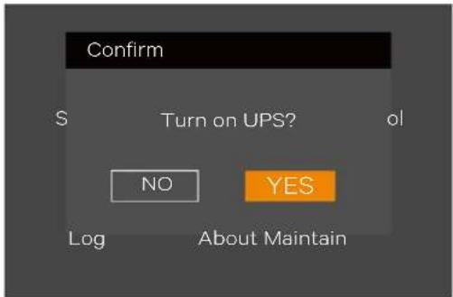
text_image
Confirm S Turn on UPS? ol NO YES Log About MaintainFigure 5-1 Turning on UPS
In Inverter mode, press and hold the power button. If the bypass is normal, the interface shown in Figure 5-2 is displayed. Select 'To the Bypass' and click OK to transfer the UPS to Bypass mode; select 'Turn off UPS' and click OK to turn off the UPS.
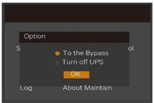
text_image
Option S To the Bypass Turn off UPS OK Log About Maintain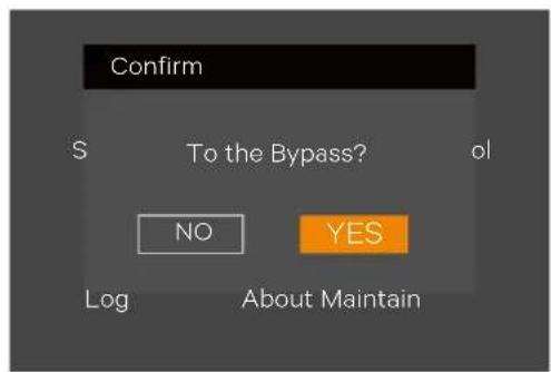
text_image
Confirm S To the Bypass? ol NO YES Log About Maintain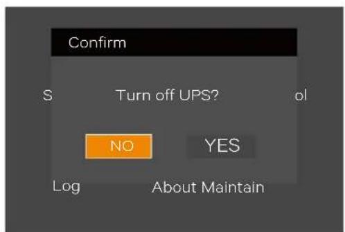
text_image
Confirm S Turn off UPS? ol NO YES Log About Maintain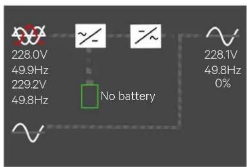
text_image
228.0V 49.9Hz 229.2V 49.8Hz No battery 228.1V 49.8Hz 0%Figure 5-2 Bypass normal interface
In Inverter mode, press and hold the power button. If the bypass is abnormal, then the interface shown in Figure 5-3 is displayed, select 'YES' to Turn off the UPS output.
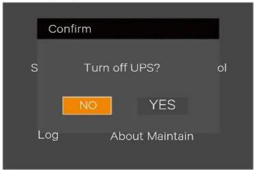
text_image
Confirm S Turn off UPS? ol NO YES Log About MaintainFigure 5-3 Bypass abnormal interface

In bypass mode, the load is directly fed by the mains power instead of the pure AC power from the inverter.
For the detailed information of the Normal mode, Bypass mode, Battery and Maintenance Bypass mode, please refer to 1.5 UPS State And Operation Mode.
5.2.3 Transfer From Bypass Mode To Inverter Mode
In Bypass mode, press and hold the power button.
If the ECO mode is not turned on, the interface shown in Figure 5-4 is displayed.
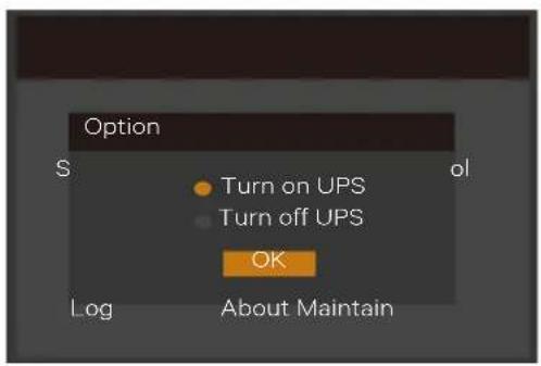
text_image
Option S ol Turn on UPS Turn off UPS OK Log About Maintain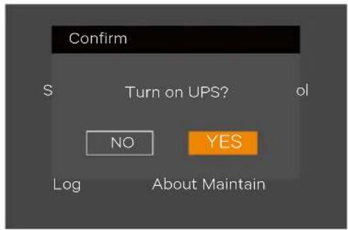
text_image
Confirm S Turn on UPS? ol NO YES Log About Maintain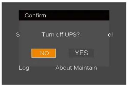
text_image
Confirm S Turn off UPS? ol NO YES Log About MaintainFigure 5-4 ECO mode not turned on
Select 'Turn on UPS' and click OK to transfer to the Inverter mode, see Figure 5-5.
Select 'Turn off UPS' and click OK to shut down the UPS output.
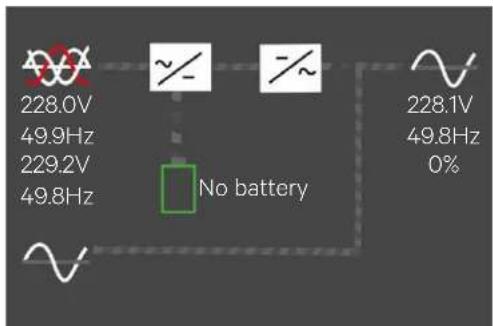
text_image
228.0V 49.9Hz 229.2V 49.8Hz No battery 228.1V 49.8Hz 0%Figure 5-5 Bypass to inverter mode
If the ECO turned on, the interface shown in Figure 5-6 is displayed. Select 'YES' to shut down the UPS output.
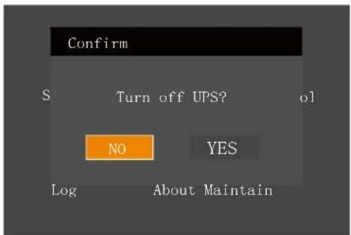
text_image
Confirm S Turn off UPS? ol NO YES Log About MaintainFigure 5-6 ECO turned on interface
5.2.4 Transfer From Inverter Mode To Maintenance Bypass Mode
When the UPS is running in Normal mode, you can use this procedure to make the load transfer from inverter output to maintenance bypass.

- Before performing this procedure, you should check the LCD information first, and ensure that the bypass is normal and synchronizes with the inverter. Otherwise, it may result in the load power interruption for a while.
-
To perform this function, user should select either a single POD or configure the MCB in maintenance bypass.
-
Through the LCD settings page, change the Dry connect 3 to 'Maintain mode'. See Figure 5-7.
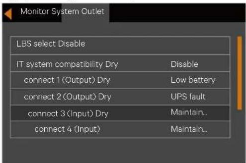
text_image
Monitor System Outlet LBS select Disable IT system compatibility Dry Disable connect 1 (Output) Dry Low battery connect 2 (Output) Dry UPS fault connect 3 (Input) Dry Maintain... connect 4 (Input) Maintain...Figure 5-7 Changing dry contact 3 to 'Maintain mode'
- Use the maintenance bypass signal cable (accessory of POD) to connect Dry Contact Port 3 of the UPS with interlock port on the POD. See Figure 5-8.
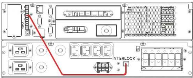
text_image
1 2 3 4 5 6 7 8 9 10 11 12 13 14 15 16 17 18 19 20 INTERLOCK INTERLOCKFigure 5-8 Ports connection (Taking ITA2 5kVA UPS and 5kVA single POD for example)
- Remove the fixing screws of the baffle of the maintenance bypass switch, then rotate the baffle upwards till it is completely fixed, finally fasten the fixing screws.
At this time, the system Interlock function is activated, the UPS will transfer to internal bypass mode, and you should confirm that the UPS has been transferred to internal bypass mode.
- After the confirmation, close the maintenance bypass switch.
Note: Dry contact port 4 can achieve the same function as dry contact port 3 via the steps mentioned above.
5.2.5 Transfer From Maintenance Bypass Mode To Inverter Mode
After UPS maintenance, use this procedure to transfer the load from the maintenance bypass to the inverter.

If the user configures the maintenance bypass switch, the UPS must be manually transferred to the bypass mode after UPS maintenance and then close the output switch. Failure to observe this may cause damage to the equipment.
- Confirm that the baffle of the maintenance bypass switch has been firmly rotated upwards.
- Close the mains input MCB and bypass input MCB on the front panel of the POD. At this time, the UPS will again power ON and operate at bypass mode.
- Confirm that the UPS has worked in Bypass mode, then close the output MCB on the front panel of the POD.
- Open the maintenance bypass MCB on the front panel of the POD. Rotate the baffle of the maintenance bypass switch to its original position, then fasten the fixing screws.
- Press the power button on the operation and display panel of the UPS, and the UPS transfers to Inverter mode.
5.3 UPS Complete Shutdown
For the UPS system with POD, if you need to shut down the UPS completely, transfer the UPS from Inverter mode to Maintenance Bypass mode according to the procedures in 5.2.4 Transferring From Inverter Mode To Maintenance Bypass Mode, so as to make no effect on the use of the load during the UPS power-off. Then if the power to the load is not needed, open the maintenance bypass MCB directly, as shown in Figure 5-9.
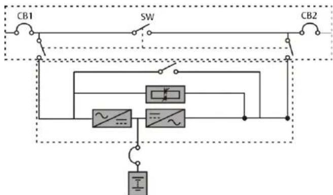
flowchart
graph TD
    A["CB1"] --> B["SW"]
    B --> C["CB2"]
    D["Power Source"] --> E["Switch"]
    E --> F["Diode"]
    E --> G["Ground"]
    H["Power Source"] --> I["Diode"]
    I --> J["Ground"]
Figure 5-9 Configuration of the UPS with external maintenance bypass
For the UPS system which the distribute power is accomplished by user, if you need to isolate the UPS from AC power, disconnect the external input MCB. (If the main and bypass are independently powered, close the two input MCBs).

Cut off the maintenance power, in order to prevent the physical injury.
5.4 REPO
Located at rear of the UPS, the REPO port is designed to switch off the UPS in emergency conditions (such as fire, flood). The system will turn off the rectifier, inverter and stop powering the load immediately (inverter and bypass output included), and the battery stops charging or discharging. Just unplug the terminal connecting to the REPO if you need emergency power-off.
If the mains input is present, the UPS control circuit remains active; however, the output is closed. To remove all mains power from the UPS, the external main input MCB should be disconnected.
5.5 Auto Restart
When the mains power fail, the UPS draws power from the battery to supply the load until the batteries are depleted, then the UPS will shut down.
The UPS will automatically restart and recover output power supply:
After the mains power is restored.
The UPS Auto Restart function is enabled.
After the Auto Restart is delayed (default: 10s). During the Auto Restart delay, the UPS charges the battery to provide a safety margin for equipment shutdown if input power fails again.
If the Auto Restart function is disabled, you can restart the UPS manually by pressing the power button.
5.6 Language Selection
The LCD menus are available in two languages: Chinese, English.
Procedures for selecting the language:
- On the main menu screen, press the ▲ or ▼ key to switch the cursor to select 'Settings', then press the Enter key to confirm it. See Figure 5-10.
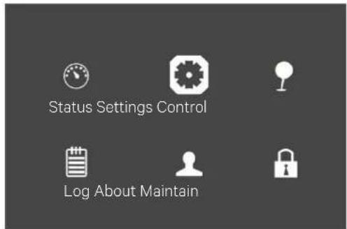
text_image
Status Settings Control Log About MaintainFigure 5-10 Main menu
- Press the ▼ key to move the cursor to 'Monitor', see Figure 5-11.
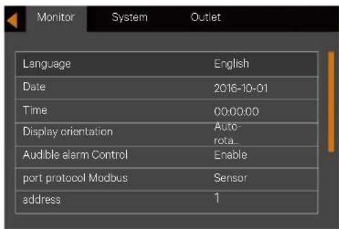
text_image
Monitor System Outlet Language English Date 2016-10-01 Time 00:00:00 Display orientation Auto- rota.. Audible alarm Control Enable port protocol Modbus Sensor address 1Figure 5-11 Monitor interface
- Press the Enter key to highlight the language, see Figure 5-12.
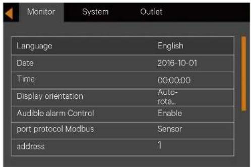
text_image
Monitor System Outlet Language English Date 2016-10-01 Time 00:00:00 Display orientation Auto- rota_ Audible alarm Control Enable port protocol Modbus Sensor address 1Figure 5-12 Language selection
- Press the ▲ or ▼ key to select your required language, then press the Enter key to confirm it. At this point, the LCD information will be the displayed in your selected language. See Figure 5-13.
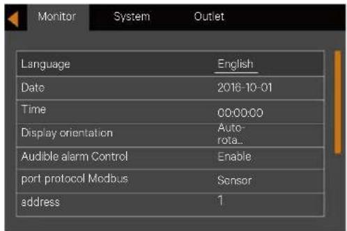
text_image
Monitor System Outlet Language English Date 2016-10-01 Time 00:00:00 Display orientation Auto- rota... Audible alarm Control Enable port protocol Modbus Sensor address 1Figure 5-13 Changing Language
- Press the Esc key for several times to back to the main menu screen.
5.7 Changing Current Date And Time
Procedures for changing the system date and time:
- On the main menu screen, press the ▲ or ▼ key to switch the cursor to select 'Settings', then press the Enter key to confirm it. See Figure 5-14.
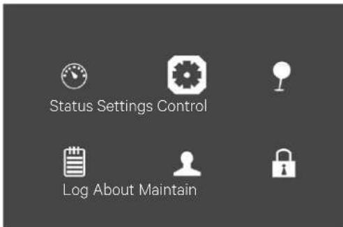
text_image
Status Settings Control Log About MaintainFigure 5-14 Main menu screen
- Press the v key to move the cursor to 'Monitor', see Figure 5-15.
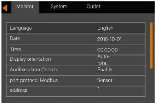
text_image
Language English Date 2016-10-01 Time 00:00:00 Display orientation Auto- rota Audible alarm Control Enable port protocol Modbus Sensor address 1Figure 5-15 Monitor interface
- Press the Enter key, and press the A or V key to highlight the date and time, see Figure 5-16.
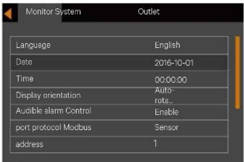
text_image
Monitor System Language Date Time Display orientation Audible alarm Control port protocol Modbus address English 2016-10-01 00:00:00 Auto- rote... Enable Sensor 1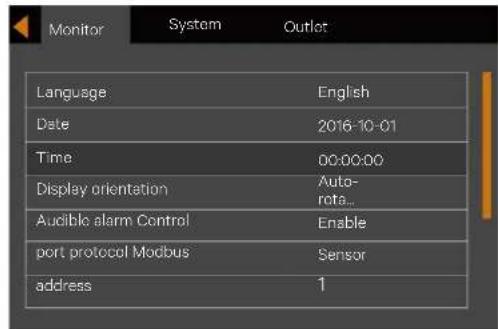
text_image
Monitor System Outlet Language English Date 2016-10-01 Time 00:00:00 Display orientation Auto- rota... Audible alarm Control Enable port protocol Modbus Sensor address 1Figure 5-16 Selection of date and time
- Press the Enter key, move the cursor and press the A or V key to change the date and time as required. See Figure 5-17.
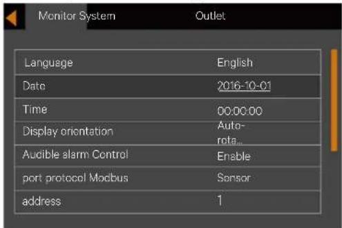
text_image
Monitor System Language English Date 2016-10-01 Time 00:00:00 Display orientation Auto- rota... Audible alarm Control Enable port protocol Macbus Sensor address 1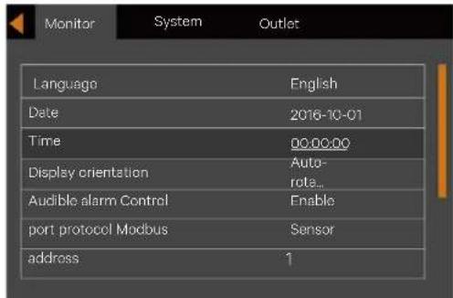
text_image
Monitor System Outlet Language English Date 2016-10-01 Time 00:00:00 Display orientation Auto- role... Audible alarm Control Enable port protocol Modbus Sensor address 1Figure 5-17 Changing date and time
- Press the Enter key to confirm it, and then press the Esc key several times to back to the main menu screen.
5.8 Setting Password
- After switching the UPS on, access the main menu screen and , press the ▲ or ▼ key to move the cursor to select 'Settings'. See Figure 5-18.
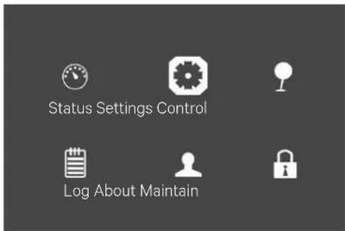
text_image
Status Settings Control Log About MaintainFigure 5-18 Main menu
- Press the Enter key, the interface shown in Figure 5-19 is displayed.
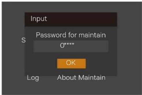
text_image
Input Password for maintain 0**** OK Log About MaintainFigure 5-19 Inputting password
To change the password, proceed as follows:
- Press the ▼ key to move the cursor to the 'Monitor', see Figure 5-20.
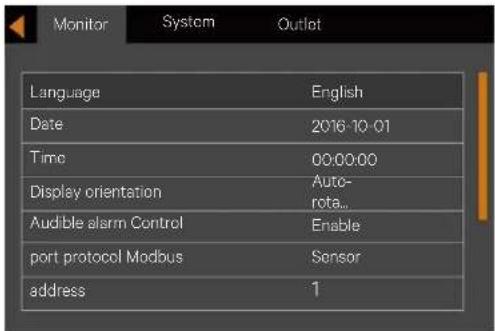
text_image
Language English Date 2016-10-01 Time 00:00:00 Display orientation Auto- rota... Audible alarm Control Enable port protocol Modbus Sensor address 1Figure 5-20 Monitor interface
- Press the Enter key, then press the V key to select the 'Change settings password', see Figure 5-21.
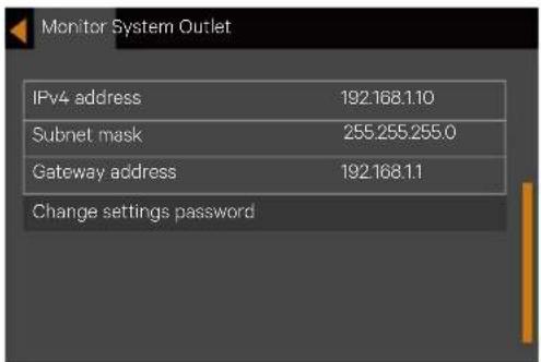
text_image
Monitor System Outlet IPv4 address 192.168.1.10 Subnet mask 255.255.255.0 Gateway address 192.168.1.1 Change settings passwordFigure 5-21 Changing settings password
- Press the Enter key, the interface shown in Figure 5-22 is displayed.
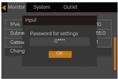
text_image
Monitor System Outlet Input IPv4 10 Subne Password for settings 55.0 Gatew 0**** 1 Chang OKFigure 5-22 Password for settings
- Enter the existing password and press the Enter key to confirm, at this point the system requests the user to enter a new password. See Figure 5-23.
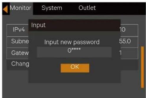
text_image
Monitor System Outlet Input IPv4 Subne Gatew Chang Input new password 0***** OKFigure 5-23 Inputting new password
- After entering the new password, press the Enter key to confirm it, at this point the system requests the user to confirm the new password by entering it again. See Figure 5-24.
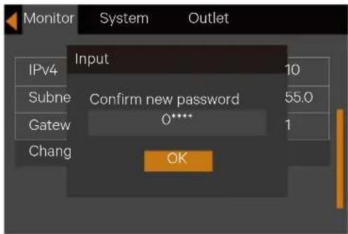
text_image
Monitor System Outlet Input IPv4 Subne Confirm new password 55.0 Gatew 0**** 1 Chang OKFigure 5-24 Confirming new password
- After the confirmation, press the Enter key and at this point system prompt a dialog box indicating that the password has been changed successfully see Figure 5-25.
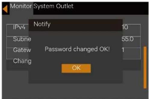
text_image
Monitor System Outlet IPv4 Notify 10 Subne 55.0 Gateway Password changed OK! 1 Chang OKFigure 5-25 Password changed OK
- Press the Esc key for several times to back to the main menu screen.

In order to access the UPS parameters, it is necessary to enter the correct password (default: 111111).
5.9 Changing output configuration
From 3-in 1-out to 3-in 3-out
- Remove all shorting copper bars of the 3-in 1-out system. Install shorting copper bars 1# as shown in Figure 5-26 (No need to install shorting copper bars for 3-in 3-out split-bypass configuration). And then connect all the cables.
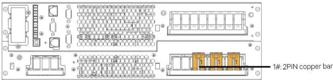
text_image
1#: 2PIN copper barFigure 5-26 Changing power distribution mode
- Unplug the EPO jumpers of the dry contact port REPO.
- Power ON the UPS system. Set the system to '3phase' through the ENTER -> 'Settings' (default password: 111111) -> 'Output' -> 'Output phase No.', and power off the system completely. Thereafter, power ON the system again, go through the setting menu to confirm that the settings are updated.
- Power OFF the system completely, restore the EPO jumpers of the dry contact port REPO.

Note: The load side switch must be Turned off during these changes
From 3-in 3-out to 3-in 1-out
- Remove all the three shorting copper bus bars 1# (3-in 3-out, common input configuration)
- Install the shorting copper bus bars (1, 2, 4, 5) as shown in Figure 5-27. And then connect all the cables.
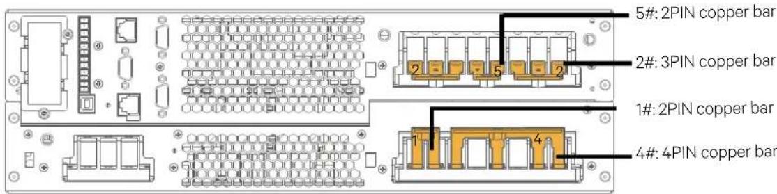
text_image
5#: 2PIN copper bar 2#: 3PIN copper bar 1#: 2PIN copper bar 4#: 4PIN copper barFigure 5-27 Changing power distribution mode
- Unplug the EPO jumpers of the dry contact port REPO.
- Power ON the UPS system. Set the system to '3phase' through the ENTER -> 'Settings' (default password: 111111) -> 'Output' -> 'Output phase No.', and power off the system completely. Thereafter, power ON the system again, go through the setting menu to confirm that the settings are updated.
- Power OFF the system completely, restore the EPO jumpers of the dry contact port REPO.

Note: The load side switch must be Turned off during these changes

Before the commissioning engineer's arrival, if the load is not ready for accepting the power, please take good care of the safety insulation at the end of the output cable.
After the configuration changes made, Commissioning Engineer should correct the AC OUTPUT & BYPASS INPUT configuration on the Label accordingly by clicking '√' as shown in Figure 5-28 (taking 20kVA for example). This label is placed on the top cover of the UPS.
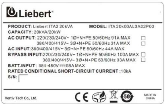
text_image
Liebert® PRODUCT: Liebert ITA2 20kVA MODEL: ITA 20k00AL3A02P00 CAPACITY: 20kVA/20kW AC OUTPUT: 220/230/240V~ 1Ø+N+PE 50/60Hz 91A MAX 380/400/415V~ 3Ø+N+PE 50/60Hz 31A MAX AC INPUT:380/400/415V~ 3Ø+N+PE 50/60Hz 44A MAX BYPASS INPUT:220/230/240V~ 1Ø+N+PE 50/60Hz 100A MAX 380/400/415V~ 3Ø+N+PE 50/60Hz 33A MAX BATT INPUT : 384-480V==58A MAX RATED CONDITIONAL SHORT-CIRCUIT CURRENT :10KA S/N: Vertiv Tech Co., Ltd. CE Made IN CHINAFigure 5-28 Label (20kVA)
6 Communication
This chapter briefly introduces the UPS communication.
The communication ports include: intelligent card port, dry contact port, built-in port, 232 port, control port and USB port.

It is recommended to make the signal cable length be less than 3m and keep away from the power cable.
6.1 Installing Intelligent Card
6.1.1 Intelligent Card Port
UPS provides an intelligent card port (see Figure 6-1, considering 20kVA model for example), to install the communication device options, including SIC card and RDU-SIC card. The intelligent card port and USB port can be used at the same time.
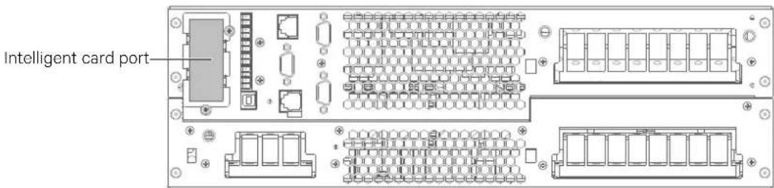
text_image
Intelligent card portFigure 6-1 Intelligent card installation (20kVA, rear view)
6.1.2 Intelligent Card Option
SIC card
SIC card is a network management card, that makes the intelligent devices (such as UPS, air conditioner, static transfer system (STS), sever power management system (SPM), and so on) produced by Vertiv have network communication capability. The SIC card can also be used with the Network Shutdown designed by Vertiv to provide safe automatic shutdown function for the computer, in which the Network Shutdown is installed, to protect data and reduce loss.
Refer to the corresponding user manual for the installation and operation guide.
RDU-SIC card
The RDU-SIC card is a network management card. It can make the intelligent equipment (such as UPS, PDU and so on) developed by Vertiv have the capacity of network communication. The SIC card can also be connected to the environment monitoring equipment, including IRM series or 1-Wire series temperature sensor, temperature & humidity sensor or dry contact signal input & detecting sensors. In case of an intelligent equipment alarm, the user is notified by multiple ways: recording, sending a Trap message, sending an E-Mail or sending an SMS.
The RDU-SIC card provides four approaches to monitor the intelligent equipment and equipment room environment:
Web browser. Monitor your intelligent equipment and equipment room environment through the Web server function provided by the SIC card
Network Management System (NMS). Monitor your intelligent equipment and equipment room environment through the SNMP agent function provided by the SIC card
RDU-Manager. RDU-Manager is a piece of management software for equipment room. You can use RDU-Manager to monitor your intelligent equipment and equipment room environment through the TCP/IP interface provided by the SIC card
Centralized management software (Nform). Monitor your intelligent equipment through the Velocity Server service function provided by the SIC card
The SiC card can also work with the Network Shutdown computer safe shutdown program developed by Vertiv to provide automatic safe shutdown function for your computer installed with Network Shutdown, so as to prevent data loss.
Refer to the corresponding user manual for the installation and operation guide
RS485 card
RS485 card should be used together with Liebert® ITA series UPS provided by Vertiv to realize the signal transform from RS232 to RS485.
Refer to the corresponding user manual for the installation and operation guide.
RS232 card
The RS232 card should be used together with the Liebert® ITA series UPS of Vertiv. It only supports RS232 protocol communication, and the maximum length of the communication cable cannot exceed 15 meters.
IS-UNITY-DP card
The IS-UNITY-DP card should be used together with the Liebert® ITA series UPS of Vertiv. For further description of the IS-UNITY-DP card, refer to Liebert IntelliSlotTM Unity Card User Manual-Web, SNMP, Modbus, BACnet, YDN23.
6.2 Connection Cables For Dry Contact Port
The UPS provides five dry contact ports. The silkprints of the five dry contact ports are 1 \~ 12. The pin layout of each dry contact port is shown in Figure 6-2, and the port description is shown in Table 6-1.
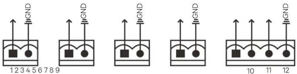
Figure 6-2 Pin layout of dry contact ports
Table 6-1 Description of the dry contact ports
| Silkprint | Port name | Pin NO. | Pin name Meaning | |
| 1 | Output port1 | 1 | LOW-BATTERY/ON_BATTERY/ON_BYPASS/UPS_FAULT | Default: LOW-BATTERY can be set via the LCD settings page. When the system has as alarm, short Pin 1 and Pin 2 |
| 2 GND | GND | |||
| 2 | Output port 2 | 3 | LOW-BATTERY/ON_BATTERY/ON_BYPASS/UPS_FAULT | Default: UPS_FAULT, can be set via the LCD settings page. When the system has as alarm, short Pin 3 and Pin 4 |
| 4 GND | GND | |||
| 3 | Input port 1 | 5 | Battery mode shutdown/Any mode shutdown (Remote Comms Shutdown)/ Maintain mode | Default: Maintain mode, can be set via the LCD settings page. When Pin 5 and Pin 6 are shorted, the function is valid |
| 6 GND | GND | |||
| 4 | Input port 2 | 7 | Battery mode shutdown/Any mode shutdown (Remote Comms Shutdown)/ Maintain mode | Default: Maintain mode, can be set via the LCD settings page. When Pin 7 and Pin 8 are shorted, the function is valid |
| 8 GND | GND | |||
| 5 | REPO input port* | 9 | +5V | REPO power supply, 5Vdc 100mA |
| 10 | REPO Coil -NC | NC, ECO activated when Pin 9 and Pin 10 opened | ||
| 11 | REPO Coil -NO | Trigger REPO when Pin 11 and Pin 12 closed | ||
| 12 | GND | REPO ground |

The I/O dry contact port capacity: 125Vdc, 0.5A; 30Vdc, 1A.
Pin11 and Pin12 reserves the corresponding terminals for configuring the REPO function. The REPO device also needs the shielded cable to connect to the Normally Open remote REPO switch between the two terminals. If not necessary, you should disconnect Pin9 and Pin10. Pin9 and Pin10 have been shorted before delivery.

The EPO action of the UPS will close the rectifier, inverter and static bypass, but it cannot disconnect the UPS from mains input. If you want to disconnect the UPS completely, just disconnect the upstream input MCB when generating the EPO.
In emergency conditions, close the REPO switch (prepared by users) to shut down the rectifier and inverter, and the UPS is powered off. In normal condition, the REPO switch cannot cut off the UPS input power. If a switch of electronic control tripping function is adopted at the UPS input, the REPO switch helps the switch to trip and thus cuts off the UPS input power. The position of the REPO switch is shown in Figure 1-3, and the REPO cable connection is shown in Figure 6-3.

text_image
REPO switch REPO REPO plug 9 10 11 12Figure 6-3 REPO cable connection
The cable connection procedures are as follows:
- Loosen the '11' and '12' connection terminals of the REPO port.
- Insert the two ends of the copper core cables with the insulation leather peeled into the '11' and '12' connection terminals of the REPO port, and press down the terminals. The REPO cable connection is complete. Ensure that the REPO cable is firmly connected to avoid no action or wrong action of the REPO caused by accidental dropping or infirm contact.
- For parallel UPSs, when connecting the REPO cable, users should parallelly connect '11' of the REPO port with one end of the electronic switch, and parallel connect '12' with the other end of the electronic switch.
When the REPO switch at the user end closes, the UPS generates an alarm and cut off the output immediately, and the UPS will not return to the normal operation state automatically. At this point, you must change the REPO switch state, and power on the UPS manually.

- It is recommended to use 0.82mm^2 0.33mm^2 (signal cable of 18AWG \~ 33AWG) copper core cable.
- If the switch you have configured is of electronic control tripping function, when the REPO signal takes action, you need to close the switch before restart the UPS.
6.3 Connecting USB Communication Cables
The methods to connect the USB communication cable are as follows:
Insert one end of the USB communication cable to the USB port (see Figure 1-3) on the rear panel of the UPS, and connect the other end to the USB port of the computer.
After the connection, install the USB drive program in the installation disk.
6.4 Connecting Serial Port Communication Cables
The methods to connect the serial port communication cable are as follows:
Insert one end of the DB9 serial port communication cable to the DB9 serial port (see port 5 in Figure 1-3) on the rear panel of the UPS, and connect the other end to the DB9 port of the computer.
The pin function of DB9 is listed below:
| Pin No. | Function |
| 2 | Send data |
| 3 | Receive data |
| 5 | Common terminal |
6.5 Connecting Control Port
The control port adopts the standard RJ45 port, which supports the Modbus/Jbus port and connects the Vertiv temperature/temperature & humidity sensor.
The user can select Modbus/Jbus protocol function or sensor function via the 'Settings' on the LCD.
6.6 Connecting Built-in Ethernet Port
The built-in Ethernet port supports the HTTP protocol. The user can connect one end of the network cable to the Ethernet port of the UPS, and connect the other end to the built-in Ethernet port of the computer. The user can remotely access the UPS via the IE, Chrome and Firefox, so as to monitor the UPS in real time.
Connect network cables: Connect one end of the network cable to the Ethernet port of the UPS, and connect the other end to the built-in Ethernet port (or the switch port, Router port) of the computer.
Set network parameters: The user should change the parameters (IP address, subnet mask, gateway address) of the computer or the UPS, so as to make the computer communicate the UPS well.
To change the network parameters of the UPS, operate them via the 'Settings'->'Monitor', as shown in Figure 6-4.
Webpage monitoring function
Open the browser (like IE), enter the IPv4 address in the login interface at the address bar. After inputting the correct user name and password (default name: user, password: 111111), you can monitor the UPS working status.
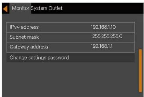
text_image
Monitor System Outlet IPv4 address 192.168.1.10 Subnet mask 255.255.255.0 Gateway address 192.168.1.1 Change settings passwordFigure 6-4 Changing UPS network parameters
Browser support
It is recommended that Internet Explorer (IE9 or above) or Chrome, FireFox (the latest version required) be used to obtain the best user experience.
Screen resolution
The display with resolution of 1024*768 or above is recommended.
7 Maintenance
This chapter focuses on the UPS maintenance, including the fan maintenance, battery maintenance, UPS cleaning, UPS state check, UPS function check.

Never attempt to carry out maintenance on the UPS while it is on line. Ensure that the UPS has been switched off completely when performing any internal maintenance operations on it..
7.1 Fan Maintenance

In order to avoid injury or damaging the device, wait until the fan is completely stationary before in-serting fingers or any tools into it.
The UPS fans are expected to run for 20000 hours \~ 40000 hours continuously. The higher the ambient temperature, the shorter the fan life is.
During the UPS operation, please verify the fan status once every half year by confirming that air blows out from the ventilation holes on the rear panel.
7.2 Battery Maintenance

-
Never reverse-connect the battery connections, otherwise the fire will occur.
-
Never attempt to open batteries since they contain electrolyte which is potentially harmful to person-nel. In the event of accidental with electrolyte, wash the affected area with abundant, clean water, and seek medical assistance immediately.
The internal battery module of the UPS is sealed, lead-acid, maintenance-free battery. The battery life depends on the ambient temperature, charge and discharge times. High ambient temperature and deep discharge shortens the battery life.
To ensure the battery life, it is required to:
Keep the ambient temperature ranging from 15^ C to 25^ C
Prevent small current discharge. Continuous battery operation time exceeding 24 hours is strictly prohibited
Charge the battery for at least 12 hours, if the battery hasn't been charged for three months at specified ambient temperature, or two months at high ambient temperature

- Check regularly the screws at the battery connection parts, fasten it immediately if not tight.
- Make sure that the safety equipment are complete and that the function is normal, especially that the settings of the battery management parameters are normal.
- Measure and record the internal temperature of the battery room.
- Check whether the battery ports are damaged or hot, and whether the chassises and the covers are damaged.
If liquid leakage and damage to the battery are found, place the battery in the anti-vitriol tank, and deal with it according to the local regulations.
The waste lead-acid battery is dangerous waste material. It is one of the national emphases to control the waste battery pollution. Its storage, transportation, usage and disposal must follow the national and local law and other criterions about the dangerous waste material and the waste battery pollution prevention.
According to the related regulations, recycle the waste lead-aid battery, and other disposal methods are prohibited. Throwing away randomly the waste lead-aid battery and other improper disposal methods can result in serious environment pollution, which will be investigated the legal responsibility.
As the provider of the lead-acid battery, Vertiv has built perfect service network and recycle system for the waste battery to assist users to deal with the waste battery by law. Contact Vertiv or the nearest service center for the detailed information of the recycle system about the waste battery.
Vertiv is not liable for the environment results caused by failure to comply with the notices in this section or to use the waste battery recycle system provided by Vertiv.
7.3 Cleaning UPS
To ensure free airflow inside the UPS: Clean the UPS periodically, especially the ventilation holes. If necessary, clean the UPS with a vacuum cleaner. Confirm that the ventilation holes are unobstructed.
7.4 Checking UPS State
It is recommended to check the UPS operation status once every half year.
Check the following items:
- Check if the UPS is faulty: Is the alarm indicator on? Are there any active UPS alarms?
- Check if the UPS is operating in Bypass mode. Under normal conditions, the UPS operates in Normal mode; if you find that it is operating in Bypass mode, determine the reason (operator intervention, overload, internal fault, etc.)
- Check if the battery is discharging: If the AC mains supply is within normal limits, the battery should not be discharged; if you find that it is operating in Battery mode, determine the reason (mains failure, battery test, operator intervention, etc.).
7.5 Checking UPS Functions

UPS functions check procedures may cause power interruption to load!
It is recommended to check the UPS functions once every half year.
Backup the load data before conducting the UPS functions check. Procedures are as follows:
- Press the power button to check if the buzzer beeps, indicators are ON and the LCD display is normal.
- Press the ESC key to check again if the indicators are ON, the LCD display is normal and the UPS has been transferred to the inverter mode.
8 Options
This chapter introduces the options of the UPS.
8.1 Option List
See Table 8-1 for the option list.
Table 8-1 Option list
| Option name | Model | Remark |
| Battery module | ITA-BCI0020k01 | (2U) Battery module with built-in 16-block 12V (9Ah) batteries |
| ITA-BCI0020k02 | (3U) Battery module with built-in 16-block 12V (9Ah) batteries | |
| POD | ITA-05k00POD01 | Single POD (5kVA/6kVA with maintenance bypass) |
| ITA-05k00POD02 | 1 + 1 POD (5kVA/6kVA with maintenance bypass) | |
| ITA-10k00POD01 | 1-in 1-out POD (10kVA with maintenance bypass) | |
| ITA-10k00POD02 | 1 + 1 POD (10kVA, 1-in 1-out with maintenance bypass) | |
| ITA-10k00POD03 | Output distribution unit (10kVA) | |
| ITA-20k00POD01 | Single POD (16kVA/20kVA with maintenance bypass) | |
| ITA-20k00POD02 | 1 + 1 POD (16kVA/20kVA with maintenance bypass) | |
| Communication cables | ITA-20k00AL3A02C00 L1 | UPS parallel communication cables (1m) |
| ITA-20k00AL3A02CL3 | UPS parallel communication cables (3m) | |
| Guide rail | GXT4-RMKIT1832 | Guide rail for rack installation |
| Dual bus assembly | ITA-20k00AL3A02C00 L2 | 16kVA/20kVA UPS LBS cables |
| Battery cabinet | U40-100 | Two-layer battery cabinet |
| Communication options | RDU-SIC | RDU SIC card is used for the Intellislot series UPS |
| UF-SNMP810 | SIC card is used for Intellislot series UPS | |
| Temperature/humidity sensor | IRM-S01T | Intelligent temperature sensor |
| IRM-S02TH | Intelligent temperature/humidity sensor |
8.2 Battery Module
8.2.1 List Of Battery Module Options
The battery module options are listed in Table 8-2.
Table 8-2 Battery module options
| Type | Name | Description |
| ITA-BCI0020k01 | Battery module (2U) | Built-in 16-block 12V 9Ah batteries, be used to prolong the running time.Note: It is recommended to extend six battery modules, at least two every time for 16kVA/20kVA UPS. The accessory of the battery module is a cable |
| ITA-BCI0020k02 | Battery module (3U) | Built-in 16-block 12V 9Ah batteries, be used to prolong the running time.Note: It is recommended to extend six battery modules, at least two every time for 16kVA/20kVA UPS. The accessory of the battery module is a cable |

-
The battery loop and the AC input are not insulated, so the hazardous voltage may exist between the battery port and the earth. Never touch them by hand to avoid electric shock.
-
Battery cables should be additionally configured. 16kVA/20kVA UPS require ITA-BCI0020k02L3, 5kVA/6kVA/10kVA UPS require ITA-BCI0020k02L4.
8.2.2 Appearance Of Battery Module
The appearance of the battery module is shown in Figure 8-1.
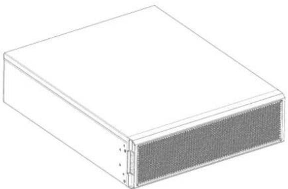
natural_image
3D rendering of a rectangular electronic device with a mesh grille (no text or symbols)Figure 8-1 Appearance of the battery module
There is no operation and display panel on the front panel of the battery module. The plastic panel can be removed and adjusted according to actual requirement, as shown in Figure 8-2.
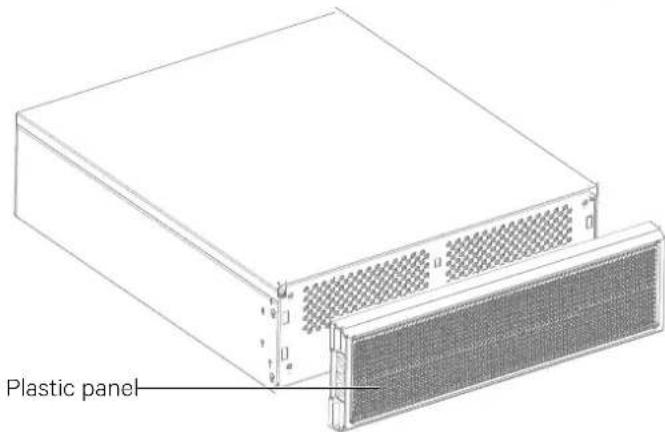
text_image
Plastic panelFigure 8-2 Removing the plastic panel
The battery module provides ventilation holes, battery ports and battery output switch on the rear panel, as shown in Figure 8-3.
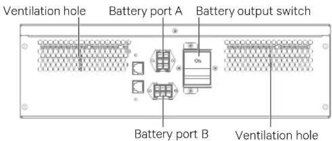
text_image
Ventilation hole Battery port A Battery output switch Battery port B Ventilation holeFigure 8-3 Rear panel of the battery module
8.2.3 Backup Time Of Standard Battery Module For Single UPS
The backup time of the ITA-BCI0020k01 & ITA-BCI0020k02 battery module is shown in Table 8-3
Table 8-3 Backup time list (Unit: min)
| Model | Module number | Backup time | |||||||||
| 5 kW | 4.5 kW | 4 kW | 3.5 kW | 3 kW | 2.5 kW | 2 kW | 1.5 kW | 1 kW | 0.5 kW | ||
| 5kVA | 1 | 5.5 | 6.5 | 7.5 | 9.5 | 11.5 | 15.0 | 20.5 | 30.0 | 49.5 | 103.5 |
| 2 | 15.0 | 17.5 | 20.5 | 25.0 | 30.5 | 39.0 | 51.0 | 70.0 | 108.0 | 235.0 | |
| 3 | 27.0 | 31.0 | 36.0 | 42.5 | 51.0 | 63.0 | 80.5 | 110.0 | 177.0 | 368.5 | |
| 4 | 39.5 | 45.0 | 51.5 | 60.0 | 71.5 | 87.0 | 104.0 | 156.5 | 246.5 | 502.0 | |
| 5 | 51.5 | 58.0 | 66.5 | 77.0 | 91.5 | 111.5 | 146.0 | 203.5 | 316.0 | 635.5 | |
| 6 | 63.5 | 71.5 | 81.5 | 94.5 | 111.5 | 139.5 | 181.5 | 250.5 | 386.0 | 768.5 | |
| 6kVA | 1 | 4.0 | 5.0 | 6.0 | 7.0 | 9.0 | 11.5 | 15.5 | 23.5 | 40.0 | 86.0 |
| 2 | 11.5 | 13.5 | 16.0 | 19.5 | 24.0 | 30.5 | 41.0 | 57.0 | 89.5 | 194.0 | |
| 3 | 21.0 | 24.0 | 28.5 | 34.0 | 41.0 | 51.0 | 66.0 | 90.5 | 143.5 | 306.5 | |
| 4 | 31.0 | 35.5 | 41.5 | 48.5 | 58.0 | 71.5 | 91.0 | 126.0 | 202.0 | 419.5 | |
| 5 | 41.5 | 47.0 | 54.0 | 63.0 | 75.0 | 91.5 | 117.0 | 165.5 | 260.5 | 532.0 | |
| 6 | 51.5 | 58.5 | 66.5 | 77.5 | 91.5 | 111.5 | 146.5 | 205.0 | 318.5 | 644.5 | |
| Model | Module number | Backup time | |||||||||
| 10kW | 9kW | 8kW | 7kW | 6W | 5kW | 4kW | 3kW | 2kW | 1kW | ||
| 10kVA | 2 | 4.0 | 4.5 | 6.0 | 8.0 | 11.5 | 15.0 | 20.5 | 30.5 | 51.0 | 108.0 |
| 3 | 8.0 | 9.5 | 11.5 | 14.5 | 21.0 | 27.0 | 36.0 | 51.0 | 80.5 | 177.0 | |
| 4 | 12.5 | 15.0 | 18.0 | 22.0 | 31.0 | 39.5 | 51.5 | 71.5 | 110.5 | 246.5 | |
| 5 | 18.0 | 21.0 | 25.0 | 30.0 | 41.5 | 51.5 | 66.5 | 91.5 | 146.0 | 316.0 | |
| 6 | 23.5 | 27.0 | 32.0 | 38.5 | 51.5 | 63.5 | 81.5 | 111.5 | 181.5 | 386.0 | |

To guarantee the backup time, it is recommended to configure at least two groups of battery modules for the 10kVA model.
| Model | Module number | Backup time | |||||||||
| 16kW | 14.4kW | 12.8kW | 11.2kW | 9.6kW | 8kW | 6.4kW | 4.8kW | 3.2kW | 1.6kW | ||
| 16kVA | 4 | 7.5 | 9.0 | 10.5 | 13.0 | 16.0 | 21.0 | 28.5 | 41.5 | 66.5 | 145.0 |
| 6 | 14.0 | 16.0 | 19.0 | 24.5 | 28.5 | 36.5 | 48.0 | 66.5 | 104.0 | 233.5 | |
| 8 | 21.0 | 24.5 | 28.5 | 34.0 | 41.5 | 52.0 | 67.0 | 92.0 | 147.5 | 322.0 | |
| 10 | 28.5 | 33.0 | 38.5 | 45.5 | 54.5 | 67.0 | 86.0 | 118.5 | 192.5 | 410.5 | |
| 12 | 35.5 | 41.5 | 48.0 | 56.0 | 67.0 | 82.0 | 105.0 | 148.5 | 240.5 | 498.5 | |
| Model | Module number | Backup time | |||||||||
| 20 kW | 18 kW | 16 kW | 14 kW | 12 kW | 10 kW | 8 kW | 6 kW | 4 kW | 2 kW | ||
| 20kVA | 4 | 5.5 | 6.5 | 7.5 | 9.5 | 11.5 | 15.0 | 21.0 | 31.0 | 51.5 | 111.0 |
| 6 | 10.0 | 11.5 | 14.0 | 17.0 | 21.0 | 27.0 | 36.5 | 51.5 | 81.5 | 181.5 | |
| 8 | 15.0 | 17.5 | 21.0 | 25.5 | 31.0 | 39.5 | 52.0 | 72.0 | 112.0 | 252.5 | |
| 10 | 21.0 | 24.5 | 28.5 | 34.0 | 41.5 | 52.0 | 67.0 | 92.5 | 148.0 | 324.0 | |
| 12 | 27.0 | 31.5 | 36.5 | 43.0 | 52.0 | 64.0 | 82.0 | 112.5 | 184.0 | 395.0 | |

To guarantee the backup time, it is recommended to configure at least four groups of battery modules for the 20kVA model.

-
The backup time will have some difference owing to the different battery manufacturer, model and using time. The data in Table 8-3 is only for reference.
-
The backup time listed in Table 8-3 is the data when the battery is in good condition. If the battery performance is reduced, the actual time of the data listed in Table 8-3 may not be achieved.
8.3 POD
POD (option of the UPS) can provide safe and reliable power distribution function. The descriptions of the POD are listed in Table 8-4.
Table 8-4 POD
| Type | Name | Description |
| ITA-05k00POD01 | Single POD (5kVA/6kVA with maintenance bypass) | (W × D × H): 430mm × 500mm × 85mm |
| ITA-05k00POD02 | 1 + 1 POD (5kVA/6kVA with maintenance bypass) | (W × D × H): 430mm × 500mm × 85mm |
| ITA-10k00POD01 | 1-in 1-out POD (10kVA with maintenance bypass) | (W × D × H): 430mm × 500mm × 85mm |
| ITA-10k00POD02 | 1 + 1 POD (10kVA, 1-in 1-out with maintenance bypass) | (W × D × H): 435mm × 500mm × 130mm |
| ITA-10k00POD03 | Output distribution unit (10kVA) | (W × D × H): 435mm × 80mm × 85mm |
| ITA-20k00POD01 | Single POD (16kVA/20kVA with maintenance bypass) | (W × D × H): 435mm × 500mm × 130mm |
| ITA-20k00POD02 | 1 + 1 POD (16kVA/20kVA with maintenance bypass) | (W × D × H): 430mm × 500mm × 261mm |
For the installation and commissioning of the POD, refer to Liebert® ITA2™ 5kVA And 6kVA UPS Power Output Distribution Unit User Manual, Liebert® ITA2™ 10kVA UPS Power Output Distribution Unit User Manual, Liebert® ITA2™ 16kVA And 20kVA UPS Power Output Distribution Unit User Manual.
Remove the plastic panel to reveal the POD front panel; remove the rear baffle plate to reveal the POD rear panel. The front and rear panel of the single POD are shown in Figure 8-4. The front and rear panel of the 1 + 1 parallel POD are shown in Figure 8-5.
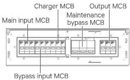
text_image
Charger MCB Output MCB Main input MCB Maintenance bypass MCB Bypass input MCBFront panel of the single POD
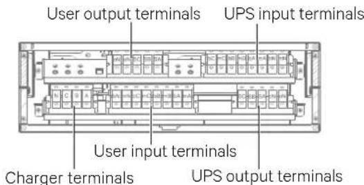
text_image
User output terminals UPS input terminals User input terminals Charger terminals UPS output terminalsRear panel of the single POD
Figure 8-4 Front panel and rear panel of the single POD (16kVA/20kVA)
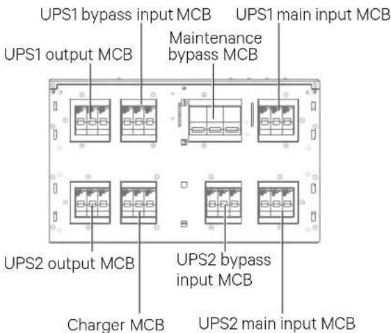
text_image
UPS1 bypass input MCB UPS1 main input MCB UPS1 output MCB Maintenance bypass MCB UPS2 output MCB UPS2 bypass input MCB Charger MCB UPS2 main input MCBFront panel of the 1 + 1 parallel POD
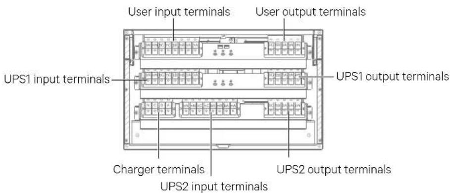
text_image
User input terminals User output terminals UPS1 input terminals UPS1 output terminals Charger terminals UPS2 output terminals UPS2 input terminalsRear panel of the 1 + 1 parallel POD
Figure 8-5 Front panel and rear panel of the 1 + 1 parallel POD (16kVA/20kVA)
8.4 Communication Cables
Communication cable is compulsory in parallel system. See Table 8-5 for cable description. Refer to 3.4.2 Connecting Parallel Cables for the methods to connect the parallel cables.
Table 8-5 Description of the communication cable
| Type | Name | Description | Appearance |
| ITA-20k00AL3A02C00L1 | Parallel communication cable | For N + 1 parallel system, N + 1 communication cables (1m) are needed. For example, two communication cables are needed in 1 + 1 parallel system; three communicatio cables are needed in 2 + 1 parallel system; four communication cables are needed in 3 + 1 parallel system |  |
| ITA-20k00AL3A02CL3 | Parallel communication cable | For N + 1 parallel system, N + 1 communication cables (3m) are needed. For example, two communication cables are needed in 1 + 1 parallel system; three communicatio cables are needed in 2 + 1 parallel system; four communication cables are needed in 3 + 1 parallel system | 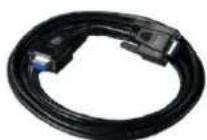 |
8.5 Guide Rail
The guide rail is used in rack installation of UPS, POD (optional) and battery module (optional). The detailed description is listed in Table 8-6.
Table 8-6 Description of the guide rail
| Type | Name | Description | Appearance |
| GXT4-RMK IT1832 | Guide rail for rack installation | A set of guide rail includes a left guide rail and a right guide rail, and its bearing is 50kg. Use the guide rail in the rack installation. It is applicable to the various server cabinet, UPS, modularize battery and POD |  |
For the rack mode installation procedure, refer to 2.5.2 Rack Installation.
8.6 Dual Bus Parts
The LBS cables are compulsory in dual bus system. See Table 8-7 for the dual bus parts.
Table 8-7 Dual bus parts
| Type | Name | Description | Appearance |
| ITA-20k00ALAA01CL5 | LBS cable | Be used to form LBS system. Two LBS cables are recommended | 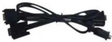 |
8.7 Battery Cabinet
If cost-saving and more backup time are required, the external battery cabinet with large capacity (battery cabinet for short) is recommended.
The battery cabinet is designed with the appearance of the e-rack cabinet, in which can embed 32-block or 30-block CSB batteries, including cables and MCBs in the battery string. The battery cabinet has vertical pole and the layer partition board with great bearing. Top and bottom cabling are available. The appearance of the battery cabinet is shown in Figure 8-6.
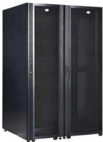
natural_image
Black server rack cabinet with two doors and ventilation grilles (no visible text or labels)Figure 8-6 Appearance of the battery cabinet

Change the battery MCB according to the system capacity.
The standard battery cabinets are listed in Table 8-8.
Table 8-8 Standard battery cabinet list
| Battery cabinet type | UPS power | Configuration | Corresponding battery (CSB) | Dimension/ Weight |
| PM32-75C4-2-50-A | ≤ 90kVA | Four layers, can load 32-block batteries;configure 250A ABB three-pole air breaker and 50mm^2 cables | 12V 100Ah | 800mm × 1100mm × 2000mm 227kg |
| PM32-38C4-50-A | ≤ 90kVA | Four layers, can load 32-block batteries;configure 250A ABB three-pole air breaker and 50mm^2 cables | 12V 26Ah12V 40Ah12V 52Ah12V 75Ah | 600mm × 1100mm × 2000mm 203kg |

- The connection cables between the battery cabinets are not configured. Please contact the local dealer if you need.
- The parallel bus bar (3 pcs) of the battery cabinet is a copper bar used to connect battery cabinets in parallel. Sets = battery cabinet number - 1.
8.8 Communication Options And Temperature/Humidity Sensor
The communication and the monitoring options are listed in Table 8-9.
Table 8-9 Communication options and the monitoring optios
| Name | Type | Description | Appearance |
| SIC card UF-SNMP810 | Remote monitor UPS through TCP/IP protocol and Internet;Support remote safe shutdown;Provide an extended net port,cascade-connect up to eight temperature humidity sensors |  | |
| RDU SIC card | RDU-SIC | Be used to connect UPS to RDU-SIC monitoring unit, or connect to the cascade-communication in parallel system |  |
| Intelligent Temperature sensor | IRM-S01T | With LCD screen, connects the SIC card or the multifunction port |  |
| Temperature humidity sensor | IRM-S08TH | With LCD screen, connects the SIC card or the multifunction port | |

When using the SIC card to connect to the temperature sensor as battery temperature compensation, connect to the COM1 port of the SIC card, and set DIP switch of the temperature sensor to '1'. For the installation and setting of the SIC card, refer to RDU-SIC Card User Manual.
Appendix 1 LCD Parameters Setting
| Menu | Item | Setting range | Default setting | |
| System | Auto restart | Disable, Enable | Enable | |
| Auto restart delay | 0~999 seconds | 10; Single unit only | ||
| Guaranteed shutdown | Disable, Enable | Disable | ||
| Remote control | Disable, Enable | Enable | ||
| Remote power on delay | 0~999 seconds | 0 | ||
| Remote shutdown delay | 0~999 seconds | 0 | ||
| Redundant | NO, YES | YES | ||
| LBS select | Disable, Master, Slave | Disable; 16kVA/20kVA only | ||
| IT system compatibility | Disable, Enable | Disable | ||
| Dry contact 1 (Output) | Low battery, On bypass, On battery, UPS fault | Low battery | ||
| Dry contact 2 (Output) | Low battery, On bypass, On battery, UPS fault | UPS fault | ||
| Dry contact 3 (Input) | Battery mode shutdown, Any mode shutdown, Maintain mode | Maintain mode | ||
| Dry contact 4 (Input) | Battery mode shutdown, Any mode shutdown, Maintain mode | Maintain mode | ||
| Output | Voltage selection | 220V, 230V, 240V | 220V | |
| Startup on bypass | Disable, Enable | Disable | ||
| Frequency selection | Auto, BypEna; Auto, BypDisa; 50Hz, BypDisa; 60Hz, BypDisa | Auto, BypEna | ||
| Inverter sync range | ±0.5Hz, ±1.0Hz, ±2.0Hz, ±3.0Hz, ±4.0Hz, ±5.0Hz | ±3.0Hz | ||
| Bypass voltage upper limit | +10%, +15%, +20% | +20% | ||
| Bypass voltage lower limit | -10%, -20%, -30%, -40% | -40% | ||
| Bypass frequency range | ±5Hz, ±10Hz | ±10Hz | ||
| Run mode | Normal, ECO mode | Normal | ||
| ECO voltage range | ±5%, ±10%, ±15% | ±10% | Appear only when the 'Run mode' is set to 'ECO mode' | |
| ECO frequency range | ±1Hz, ±2Hz, ±3Hz | ±3Hz | ||
| ECO requalification time | 5, 15, 30 (min) | 30 | ||
| Output phase No. | 1 phase, 3 phases | 3 phases (16kVA/20kVA) | ||
| Parallel | Voltage selection | 220V, 230V, 240V | 220V | |
| Frequency selection | Auto, BypEna; Auto, BypDisa; 50Hz, BypDisa; 60Hz, BypDisa | Auto, BypEna | ||
| Run mode | Normal, ECO mode | Normal | ||
| Redundant | NO, YES | YES | ||
| System parallel No. | 1~4 | 1 | ||
| Output phase No. | 1 phase, 3 phases | 3 phases (16kVA/20kVA) | ||
| Sync parallel parameters | Button | Button | ||
| Battery | Shared battery | Disable, Enable | Disable; 16kVA/20kVA only | |
| Local/Parallel battery total Ah | 7~3000Ah | 9Ah (5/6/10kVA)18Ah (16/20kVA) | ||
| External battery cabinet group No. | Auto test, 0~10 | Auto test | ||
| Low battery time | 2~30 (min) | 2 | ||
| Battery replaced time | YYYY-MM-DD HH:MM:SS | 2000-01-01 0:00:00 | ||
| Battery test interval | Disable, 8 weeks, 12 weeks, 16 weeks, 20 weeks, 26 weeks | Disable | ||
| Battery test weekday | Sunday, Monday, Tuesday, Wednesday, Thursday, Friday, Saturday | Wednesday | ||
| Battery test time | HH:MM:SS | 0:00:00 | ||
| Battery series | 5kVA/6kVA/10kVA: 12, 16, 2016kVA/20kVA: 24, 32, 40 | 16 (5kVA/6kVA/10kVA), 32 (16kVA/20kVA) | ||
| Discharge protect time | 1~4320 (min) | 4320 | ||
| Equal charge enable | NO, YES | NO | ||
| Temperature compensation | Disable, Enable | Disable | ||
| Replace battery | Button | Button | ||
| Outlet | Turn on outlet | Appear only when outlet off | ||
| Turn off outlet | Appear only when outlet on | |||
| Reboot outlet | Appear only when outlet on | |||
| Turn off when UPSoverload on battery | YES, NO | NO | ||
| Outlet | Turn off when UPS on battery for | 0~4320 (min) | 2 | |
| Turn off when backup time less than | 0~4320 (min) | 0 | ||
| Turn off when battery capacity less than | 20~80% | 30% | ||
| Turn on when power returns for | 0~4320 (min) | 0 | ||
| Monitor | Language | English, Chinese | English | |
| Date | YYYY-MM-DD | 2016-10-01 | ||
| Time | HH:MM:SS | 00:00:00 | ||
| Display orientation | Auto-rotate, Horizontal, Vertical | Auto-rotate | ||
| Audible alarm | Enable, Disable | Enable | ||
| Control port protocol | Modbus, Sensor | Sensor | ||
| Modbus address | 1~128 | 1 | ||
| IPv4 address | ddd.ddd.ddd.ddd ('d' is a decimal number) | 192.168.1.10 | ||
| Subnet mask | 255.255.255.0 | |||
| Gateway address | 192.168.1.1 | |||
| Change settings password | The password is numeric only and can be set from 0 to 9. The password length is 6 | 111111 | ||
Appendix 2 Glossary
| AC | Alternating current |
| CB | Circuit breaker |
| CSA | Cross sectional area |
| DC | Direct current |
| DIP | Dual in-line package |
| DSP | Digital signal processor |
| EMC | Electromagnetic compatibility |
| EMI | Electromagnetic interference |
| EOD | End-of-discharge |
| EPO | Emergency power off |
| I/O | Input/output |
| LBS | Load bus synchronizer |
| LCD | Liquid crystal display |
| LED | Light-emitting diode |
| MCB | Miniature circuit breaker |
| NMS | Network management system |
| PE | Protective earth |
| RCCB | Residual current circuit breaker |
| RCD | Residual current detector |
| REPO | Remote emergency power off |
| RFI | Radio frequency interference |
| SCR | Silicon-controlled rectifier |
| SNMP | Simple network monitoring protocol |
| STS | Static transfer switch |
| UPS | Uninterruptible power system |
Appendix 3 Hazardous Substances And Content
| Parts | Hazardous substances | |||||
| Plumbum | Hydrargyru | Cadmium | Chrome6+ | PBB | PBDE | |
| (Pb) | (Hg) | (Cd) | (Cr (VI)) | (PBB) | (PBDE) | |
| Cables | × O O | O O O | ||||
| This table is made following the regulation of SJ/T 11364.○: Means the content of the hazardous substances in all the average quality materials of the parts within the limits specified in GB/T 26572×: Means the content of the hazardous sustances in at least one of the average quality materials the parts is outsides the limits specified in GB/T 26572 | ||||||
| Applicable scope: Liebert® ITA2TM 5kVA ~ 20kVA UPS | ||||||

VERTIV™
VertivCo.com | Asia-Pacific
© 2017 Vertiv Co. All rights reserved. Vertiv and the Vertiv logo are trademarks or registered trademarks of Vertiv Co. All other names and logos referred to are trade names, trademarks or registered trademarks of their respective owners. While every precaution has been taken to ensure accuracy and completeness herein, Vertiv Co. assumes no responsibility, and disclaims all liability, for damages resulting from use of this information or for any errors or omissions. Specifications are subject to change without notice.