DW716N-1000 - Security Camera Digital Watchdog - Free user manual and instructions
Find the device manual for free DW716N-1000 Digital Watchdog in PDF.


User questions about DW716N-1000 Digital Watchdog
0 question about this device. Answer the ones you know or ask your own.
Ask a new question about this device
Download the instructions for your Security Camera in PDF format for free! Find your manual DW716N-1000 - Digital Watchdog and take your electronic device back in hand. On this page are published all the documents necessary for the use of your device. DW716N-1000 by Digital Watchdog.
USER MANUAL DW716N-1000 Digital Watchdog
Please read this manual thoroughly before use, and keep it handy for future reference.

text_image
DW DIGITAL WATCHDOGEverything's Digital
USER GUIDE
DIGITAL
RECORDING SYSTEM
DW-708N/716N/908N/916N
Series
DW-6/7 Series Manual
◆ If you require additional copies of this manual, please print the manual contained in the CD provided with your purchase.
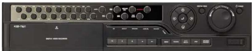
text_image
KSR-T601 KSR-T601Introduction
Thank you for purchasing this product.
This DVR is produced by the most advanced technology and its quality is guaranteed by strict reliability and compatibility testing.
This product manual provides necessary information for the correct use of this product and also contains some useful tips.
Please read this manual thoroughly before using in order to prevent possible breakdown due to any mishandling.
Caution
Please be aware of the following precautions before installing the DVR.
- Avoid positioning the DW-6/7 series in any place where the unit may come into contact with moisture, dust, or soot.
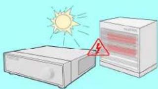
- Avoid placing in direct sunlight or near heating appliances.
- Keep the product away from electric shock or magnetic substances.
- Avoid temperature extremes (recommended operation temperature is between 0^ and 40^ ).
- Do not place any conductive material through the ventilation grills.
- Keep the system turned off before installation.
- Ensure enough space is left for cable connections.
- Place the system on a solid surface with sufficient air ventilation. Avoid any surface that vibrates.
- Placing the system near electronic devices such as radio or TV may cause breakdown to the product.
- Do not place any heavy object on the system.
Safety Warnings and
Ca utions
The following are warnings and cautions for the safety of the users and for the prevention of any property damage. Please read below thoroughly.
Warning and Caution signs
| WarningIf you are not aware of this warning, you may be seriously injured or be killed. | CautionIf you are not aware of this caution, you may be injured or cause property loss. |
 | Warning |
Turn off the system before installing the system.Do not plug in several electric devices to the same outlet.This may cause heating, fire, or electric shock.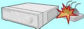 | Do not place any liquid container on the system, such as water, coffee, or beverage.If liquid is poured onto the system, it can cause a system breakdown or cause fire.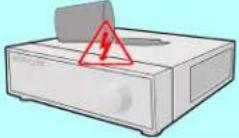 |
Prevent power cable from being severely bent or pressed by a heavy object.This may cause fire.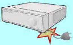 | Clean the dust around the system on regular basis. When cleaning the system, always use dry cloth. Do not use wet cloth or other organic solvents.This may damage the surface of the system and can cause system breakdown or electric shock.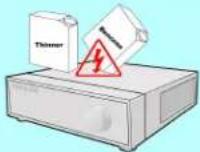 |
Avoid any place with moisture, dust, or soot.This can cause fire or electric shock.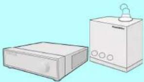 | When pulling the power cable from the plug, do so gently. Do not touch the plug with wet hands and avoid using the plug if the holes on the outlet are too loose.This may cause fire or electric shock.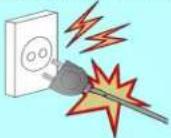 |

Warning
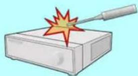
Do not attempt to disassemble, repair, or modify the system on your own. It is extremely dangerous due to high voltage running through the system.
• This may cause fire, electric shock, or serious injuries.
natural_image
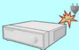
Illustration of a soldering iron on a rectangular base with a red starburst effect (no text or symbols)Check for any danger signs such as moist floor, loosened or damaged power cable, or unstable surface. If you encounter any problems, ask for assistance from your dealer.
- This may cause fire or electric shock.
natural_image
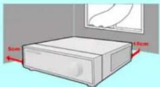
Illustration of a white electronic device with a fuse emitting a flame (no text or symbols)Keep at least 15cm between the back of the system and a wall for the cables connected into the system. Otherwise, cables may be bent, damaged, or cut.
- This may cause fire, electric shock, or injuries.
natural_image
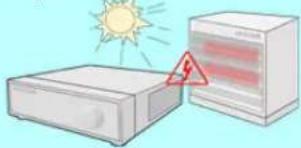
Illustration of a white rectangular box placed indoors with a 5cm measurement label and a window on top (no text or symbols on the box itself)Install the system in a cool place without direct sunlight and always maintain room temperature. Avoid candle light and heat-generating devices such as heater. Keep the system away from places where many people pass.
- This may cause fire.
natural_image
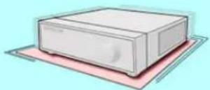
Illustration of a sun heating next to a refrigerator with a warning triangle (no text or symbols)Install the system on a plain surface with sufficient air ventilation. Do not place the system on elevated surface.
• This may cause system breakdown or serious injuries.
The power outlet must be placed on a ground, and the voltage range must be within 10% of the voltage rate. Do not use the same outlet with a hair dryer, iron, refrigerator, or any heating appliances.
- This may cause fire, heating, an electric shock.

Warning
When the system's battery is depleted, you must change it with the same or equivalent type of battery specified by the manufacturer. Depleted batteries should be discarded according to manufacturer's instructions.
• This may cause an explosion.
If the system's HDD has exceeded its life span, you may not be able to recover any data stored inside the HDD. If the video on the system screen appears 'damaged' while playing a recording stored inside the system's HDD, it must be replaced with a new one. Ask for an engineer's assistance for HDD replacement from your dealer.
- Provider is not responsible for deleted data caused by user's mishandling.
CALIFORINIA USA ONLY
This Perchlorate warning applies only to primary CR (Manganese Dioxide) Lithium coin cells in the product sold or distributed ONLY in California USA.
"Perchlorate Material - special handing may apply, See www.dtsc.ca.gov/hazardouswaste/perchlorate."

Caution
Do not install the system in a place with high magnetic, electric wave, or wireless devices such as radio or TV.
• Install the system in a place without magnetic objects, electric frequencies, or vibration.

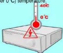
Install the system in a place with appropriate moisture and temperature level.
- Avoid installing the system with high (over 40 °C) or low (under 0 °C) temperature.
text_image
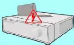
40°C 0°CPrevent any substances from being inserted into the system.
• This may cause system breakdown.
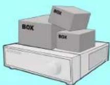
Do not place any heavy object on the system.
• This may cause system breakdown.
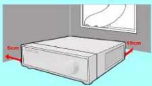
Install the system in a place with sufficient air ventilation.
- Keep at least 15cm distance between the back of the system and a wall, and at least 5cm distance between the side of the system and a wall.
natural_image
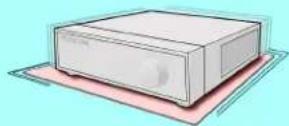
Illustration of a rectangular electronic device with two red arrows indicating dimensions (5cm and 15cm), no text or symbols present.Install the system on a stable and leveled surface..
• The system may not operate properly.
Caution
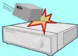
The system can be damaged from a strong impact or vibration. Avoid throwing objects within the vicinity of the system.
natural_image
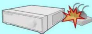
Illustration of a computer with a box and explosion effect (no text or symbols)Avoid direct sunlight or any heating appliances.
natural_image
Illustration of a sun heating next to a device with a warning triangle (no text or symbols)Ventilate the air inside the system operation room, and tighten the system cover firmly.
- System breakdown may be cause by inappropriate environment.
It is recommended to use AVR (Automatic Voltage Regulator) for stable power supply.
It is recommended to coil the core-ferrite around the connector of the system to avoid electromagnetic interference.
The outlet must be placed on the ground.
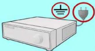
natural_image
Illustration of a white electronic device with two red electrical symbols (no text or labels)If there is strange sound or smell, unplug the power cable immediately and contact the service Center.
• This may cause fire or electric shock.
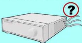
natural_image
Illustration of a beige electronic device with a red question mark and swirling lines, no text or symbols present.Do not overturn the product under use.
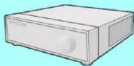
In order to maintain stable system performance, have your system checked regularly by the service Center.
- Provider is not held responsible for system breakdown caused by user's mishandling.
E q uip me nt
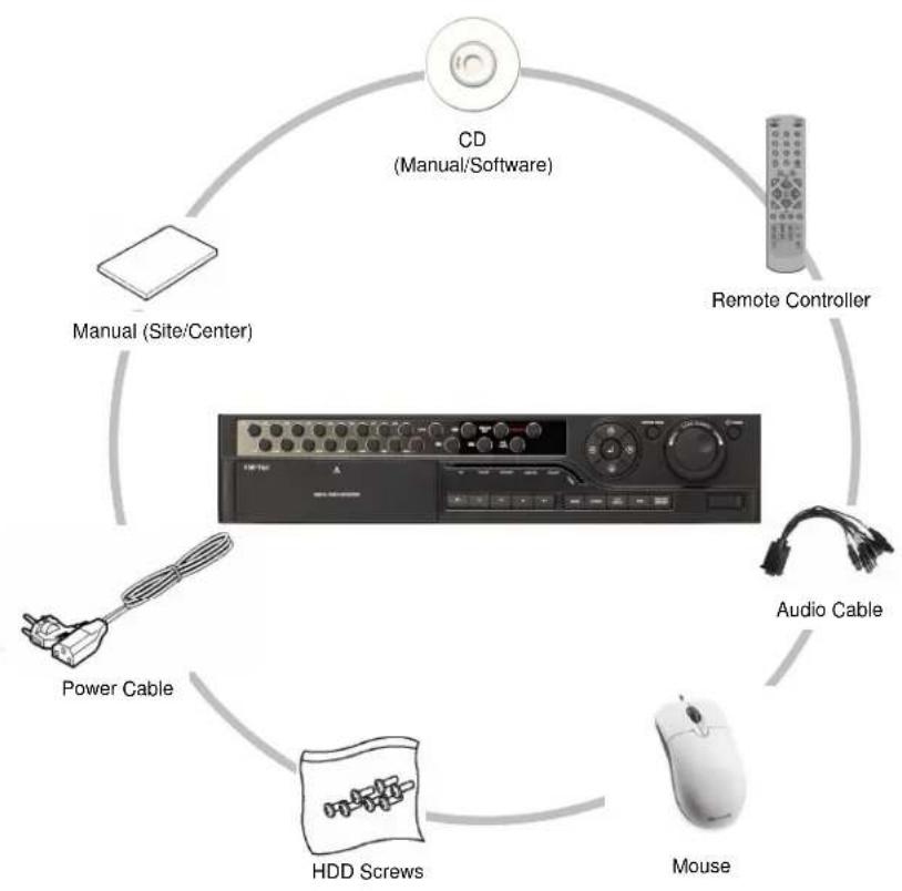
Please check to make sure the following equipment are included when you purchased DVR. If any items are missing, contact your dealer.
(The user manual will be included either inside the product software CD or a quick Manual including important contents.)
flowchart
graph TD
    A["CD (Manual/Software)"] --> B["Remote Controller"]
    B --> C["Mouse"]
    C --> D["HDD Screws"]
    D --> E["Power Cable"]
    E --> F["Audio Cable"]
    F --> G["Manual (Site/Center)"]
    G --> A
Contents
Chapter 1. Introducing your real time DVR
1.1 Front Panel....15
1.2 Rear Panel....18
1.3 Description of the Remote Controller....23
Chapter 2. Installation
2.1 Checking install environment....24
2.2 Pan/Tilt Connection....26
2.3 KEYBOARD Controller....27
2.4 Connecting LAN/PSTN Communication Lines....28
2.4.1 LAN and Dedicated Line Connection....28
2.4.2 PSTN (telephone line) Connection (optional)....29
2.5 External Alarm In Connection (Input)....30
2.6 Alarm Out Port Connection (Output)....31
Chapter 3. Live
3.1 Screen layout ....33
3.2 Enabling full screen and sequence mode....34
3.3 POP-UP MENU....35
3.4 Pan/Tilt Camera....37
3.4.1 Switching to Pan/Tilt control mode....37
3.4.2 Pan/Tilt Camera Control....38
3.4.3 Supported Pan/Tilt Camera List....39
3.5 ALARM OUT - Manual Control....40
3.5.1 Switching to Alarm Out mode....40
Chapter 4. System setup
4.1 Accessing Setup mode....42
4.2 Recording menu....42
4.2.1 Motion detection....43
4.2.2 Schedule....45
4.2.3 Quality/Resolution....46
4.2.3.1 Normal REC Setting....46
4.2.3.2 Alarm REC Setting....47
4.2.3.3 Network REC Setting....48
4.2.3.4 Alarm REC Time 49
4.2.4 Property 50
4.3 Camera menu....51
4.3.1 Channel Setting....51
4.3.2 Alarm In Setting....52
4.3.3 Alarm In Out link....53
4.3.4 Alarm In Camera link....53
4.3.5 Spot Out Camera link....54
4.4 Network.... 55
4.4.1 DDNS Setup....55
4.4.2 Network Setup....56
4.4.3 Network Test....57
4.4.4 NTP Setup....58
4.4.5 Emergency Notification....60
4.5 System Setup....63
4.5.1 User Management....63
4.5.1.1 Password Setup....64
4.5.1.2 User Addition Setup....64
4.5.1.3 Group Setup 65
4.5.2 Site Setup....66
4.5.2.1 Regional Setting....66
4.5.2.2 OSD Dwell Time....68
4.5.2.3 Remote Control ID 69
4.5.2.4 Beep Setup....69
4.5.2.5 Live Audio....70
4.5.3 Software Upgrade....71
4.5.4 Schedule....72
4.5.4.1 Backup Schedule....72
4.5.4.1.1 Adding Backup schedule....73
4.5.4.1.2 Deleting Backup schedule....74
4.5.4.2 System Restart....74
4.5.5 Storage....75
4.5.5.1 External Storages....75
4.5.5.2 Hard Disk Format....76
6 System Info....78
4.6.1 Log Info....78
4.6.2 Factory Default....81
4.6.3 System Shutdown/Restart 81
Chapter 5. Search
5.1 Accessing Search Mode ....83
5.2 Search mode display....83
5.3 Selecting date and time 84
5.4 Selecting cameras and changing search bar line....85
5.5 Audio Output....86
5.6 Playback....87
5.7 Event Search....88
Chapter 6. Backup
6.1 Video Backup ....90
6.2 Still Image Backup....91
6.3 Media Format....92
Appendix
- KDB Viewer....94
1.1 How to run Viewer....94
1.2 Viewer main screen....97 - WebDVR....100
- Watermark Checker....104
- Adding HDD....106
4.1 Installing new HDD....106
4.2 Checking HDD Database....107
- Specifications....108
- FAQ....110
1. Introducing your real time DVR
1.1 Front panel
The following describes the keys and ports on the front of the system and their functions:
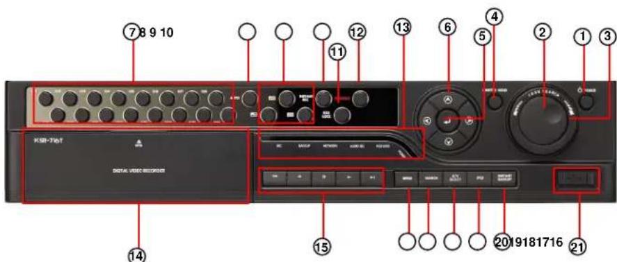
text_image
7 8 9 10 11 12 13 6 4 5 2 1 3 KSR-T68 DIGITAL VIDEO RECORDER 15 20 19 18 17 16 21[Figure 1-1. System front view(DW-716T)]
① [Power]
- Use this button to shutdown the DVR.
- When the button is pressed a password menu will pop-up and password details should be entered click [OK] and the DVR will turn off.
② [Jog (Inner dial)]
- Rotate to view recordings, in Search mode, forwards or backwards one frame at a time.
Rotate to change the value of options one unit at a time in Setup mode.
When controlling P/T/Z camera, rotate to shift camera lens focus.
③ [Shuttle (outer dial)]
- Rotate to play the recordings, in Search mode, forward or backward.
- Rotate to change the value of options continuously in Setup mode.
- When controlling P/T/Z camera, rotate to zoom in or out.
④ [HOLD]
- When using the Shuttle dial you can press the [HOLD] button to maintain the present shuttle speed.
- Press the [HOLD] button again to deactivate the feature.
⑤ [Enter Key]
- Use to select option in Setup or Search mode. Use to directly go to Control setup mode from the Surveillance mode.
⑥ [Directional keys]
- Use to move through the menu options in Setup or Search mode.
- When controlling P/T/Z camera, press the directional keys to move the camera.
- When searching recorded image, you can adjust the size of the image using up and down directional key.
[Note] OSD Position Control Function
- It is possible to control OSD position by Up/Down/Left/Right button on 16 division screen.
⑦ [Camera/Number keys]
- In Surveillance mode, press for full screen display of that camera.
- In Search mode, press for full screen display of that camera recording during playback.
- Press the keys enter correct numeric password when accessing Setup or Search modes.
⑧ [AUTO]
- Press [AUTO] to begin automatic channel sequence in full screen mode.
⑨ [Split screen buttons]
- On Surveillance or Search modes, press to select 4-splitscreen, 9-splitscreen or 16-split screen.
⑩ [INSTANT REC]
- In the case of an emergency or an emergency night happen press the [INSTANT REC] button.
- Use the [INSTANT REC] button to record video data from all cameras regardless of the recording schedule.
⑪ [KEY LOCK]
- The [KEY LOCK] button can be used lock the buttons on the front of the DVR system.
- When activating and deactivating the key lock function a password menu will pop-up and password details should be entered to switch between modes.
⑫ [EMERGENCY]
- Use the [EMERGENCY] button to transmit video data to a remote location in the case of emergency.
⑬ [LED Status Panel]
-The LED Status Panel displays the current operation state of the DVR.
![Digital Watchdog DW716N-1000 - ⑬ [LED Status Panel] - 1](/content/2026/05/819966/images/436d00f143e5e9d30f95869ca6080e3c6ff0cfc1f710b49067e86f07a5e1bedb.jpg)
text_image
REC BACKUP NETWORK AUDIO SEL KEY LOOK POWERREC : The light indicates that the DVR is recording.
BACKUP : The light indicates when a backup is in progress.
NETWORK : The light indicates that a client is connected remotely.
AUDIO SEL : The light indicates when the audio select function is active.
REMOTE : The light indicates that a button has been pressed on the remote controller.
KEYLOCK : The light indicates when the key lock function is active.
POWER : The light indicates that the power is on.
⑭ [CD/DVD-RW]
- The CD-RW/DVD-RW is used to backup video data.
⑮ [Search mode control Keys]
- In Search mode, use these keys to view the recording from either the first or last recorded
Image, to play the recording either forwards or backwards, and pause the recording.
16 [MENU]
- To go to the system configuration window, press the [MENU] button. You will then be
asked to enter the user ID and password. To exit the current menu or to close the
configuration window, press [MENU] button.
⑰ [SEARCH]
- To go to the search window, press the [SEARCH] button. You will then be asked to enter the
ID and password.
⑱ [A/V SELECT]
- The [A/V SELECT] Button can be used to select and hear audio in the surveillance screen mode.
- Press [A/V SELECT] button to activate the live audio select mode then press the Channel
button you wish to listen.
⑲ [REVERSE PLAYBACK]
- USB the [REVERSE PLAYBACK] button to playback a selected channel in surveillance
mode.
⑳ [INSTANT BACKUP]
- The [INSTANT ACKUP] button once pressed automatically makes a back-up of all channels
for the 5 minutes prior to the button being pressed to the USB port.
②1 [USB Port]
- You can connect a portable disk drive to USB port to save backup of recorded video.
- You can update your system software with an upgrade package through the USB port.
- You can control screen menu with connecting USB type mouse.
1.2 Rear panel
The following describes keys and ports on the rear part of the system and their functions.
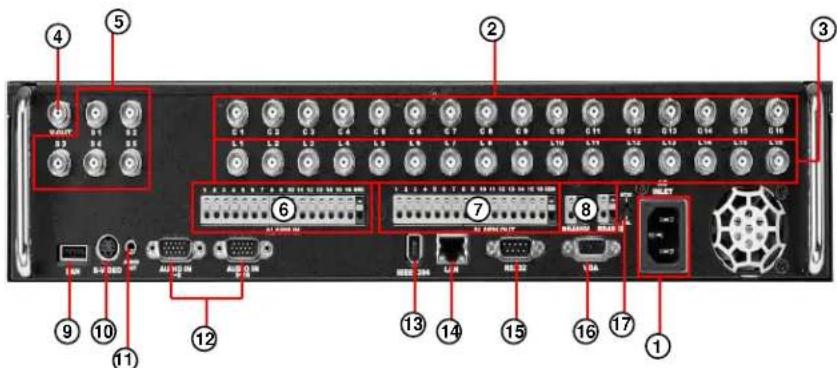
text_image
Labeled diagram of a network equipment rack with numbered ports and connectors[Figure 1-2. System rear view(DW-716T)]
① [Power Connector]
• Power cable input, 110V \~ 220V, for system main power supply.

- Be careful of electrocution. Please read [Safety Warnings and Cautions].
② [Camera Video Input BNC]
- Connecting cameras to DVR, input the video signal coaxial cable to the BNC input on the DVR.
③ [Loop Through Output]
- Video output ports for camera loop through to view images on another monitor or device. - The system supports both NTSC and PAL.
④ [V-Output Port]
- Video output for connecting with CVBS monitor.
⑤ [SPOT Monitor Output]
- Spot monitor output for video output connection to a external Spot monitor.
- Dependant on the grounding status of the power supply electric current that can cause an electric shock may flow in the video line (coaxial cable). Turn off the system before connecting the video line to the BNC port.
⑥ [ALARM IN Port]
- This is the input port for sensor devices.
•The system supports NC(Normal Close) and NO(Normal Open) sensor types.
⑦ [ALARM OUT Port]
• This is the output port for alarm out devices
- The system supports NC(Normal Close) and NO(Normal Open) control types.
![Digital Watchdog DW716N-1000 - ⑦ [ALARM OUT Port] - 1](/content/2026/05/819966/images/b1ca539211d167b153d86b3bbb21d13bf3b8eb52ecee4ffa4f146c65389301cb.jpg)
[Caution]
- Since control devices use output in a contact point format without polarity at the control output port, do not connect AC 110V \~ 220V of the power cable or supply DC power.
- When controlling DC power, it is recommended that you cut the (-ve) line.
⑧ [RS485 M/RS485S]
- RS-485M output for controlling PTZ cameras.
- RS-485S input for external devices such as keyboard controller or POS system.
- If a device is connected to the RS-485 input then the RS-232 port does not work.
⑨ [USB]
- You can connect a portable disk drive to USB port to save backup of recorded video.
- You can update your system software with an upgrade package through the USB port.
- You can control screen menu with connecting USB type mouse.
⑩ [S-VIDEO]
- S-Video output for connecting with SVGA monitor.
⑪ [AUDIO OUT]
- Connect speakers to the Audio Out port in order to output Audio data.
[Note]
- The DVR is not equipped with an audio output amplifier. Thus, user are advised to purchase separate amplifiers and speakers or speakers with a built-in amplifier.
⑫ [AUDIO IN]
- Input speaker into the audio in ports.
- Supports recording of up audio channels.
| DW-716TDW-708TDW-616TDW-608TDW-604TModel | |||||
| Audio Channels | 16CH8CH8CH8CH4CH |
⑬ [IEEE 1394]
- To use an IEEE1394 external storage as the 'Recording device' or 'Backup device'.
⑭ [LAN]
- Ethernet 10/100 connection port for connection the system through network.
- To access the network through the network hub, connect the network cable to the LAN port.
- You can remotely monitor, search, and control data on the network.
⑮ [External modem terminal] NO AVAILABLE IN EUROPEAN MODELS
- Provide a connection to the external modem for a remote access.
- You can remotely monitor, search, and control data through modem access.
- If the RS-232 port is used then the RS-485 S will not function.
⑯ [VGA]
- Connect the VGA monitor to the VGA port.
- Displays the DVR system on the monitor.
⑰ [NTSC/PAL Setup]
- The DVR supports both NTSC and PAL formats. Before turning on the DVR, select the NTSC or PAL video format.
[Note] Removable Disk
- The table below lists compatible USB disks. If you want to use other removable disk, it should be compatible with Linux 2.6.0 or over. Other USB disk may not work properly.
- It is recommended that you confirm through the manufacturer the Linux compatibility of the removal disk you wish to purchase.
- The USB disk should be formatted as FAT 32. DVR does not supports NTFS or other file system.
- When the memory of the portable USB disk is partitioned, or a password has been set, the system will not recognize the disk. Combine partitions in the memory and unlock the password before connecting the disk to the system.
- Since some USB HDDs do not generate power at all or generate only low-voltage power, a separate power source is required for such USB HDDs to enable the system to recognize them.
- Only when the memory of the USB HDD is formatted as the main partition will the system recognize the USB HDD. If it is formatted as an extension partition, however, the system will not recognize the USB HDD.
* Removable Disk support
| No. | Name | Company | USB Version |
| 1 | AnyDrive | AL-tech | Ver 1.1 |
| 2 | Unidrive | KMIT | Ver 1.1 |
| 3 | Nextdrive | JUNGSOFT | Ver 1.1 |
| 4 | SHELLGINO N4 | SHELLGINO | Ver 1.1 |
| Ver 1.1TRANSCEND TRANSCEND JF A 128M | |||
| Ver 2.0TRANSCEND JetFlash | |||
| 7 | MemoRive 2.0 Pro | FM Semicon | Ver 2.0 |
| 8 | SANDISK | SANDISK | Ver 2.0 |
| 9 SELF I&FSELF I&C | Ver 2.0 | ||
| 10 | TRUTION-512MB | TRUTION | Ver 2.0 |
| 11 | CELLDISK 2.0 | IOCELL | Ver 2.0 |
| 12 | SIMBADDA 2.0 | DAO | Ver 2.0 |
| 13 | FIEX 2.0 | SAROTECH | Ver 2.0 |
| Ver 2.0IMATIONiflash EX 2.014 | |||
| Ver 2.0TWINMOSMobile Disk Z4 2.015 | |||
| Ver 2.0CELLINKHCC-713C16 | |||
| Ver 2.0TRANSCEND TRANSCEND JF 11017 | |||
| Micro Vault18 | Ver 2.0SONY | ||
| Ver 2.0ZIBENE-D900-03-225619 | |||
| MEMORETTEFMR-memorotte(B) | Ver 2.0 | ||
| Ver2.0IMATIONIMN-IC | |||
| 22 | BLS-ITCC-BO IA | ILIAD | Ver 2.0 |
1.3 Description of the Remote controller
The following describes the remote controller buttons, which have the same functions as the buttons on the front panel of the system:
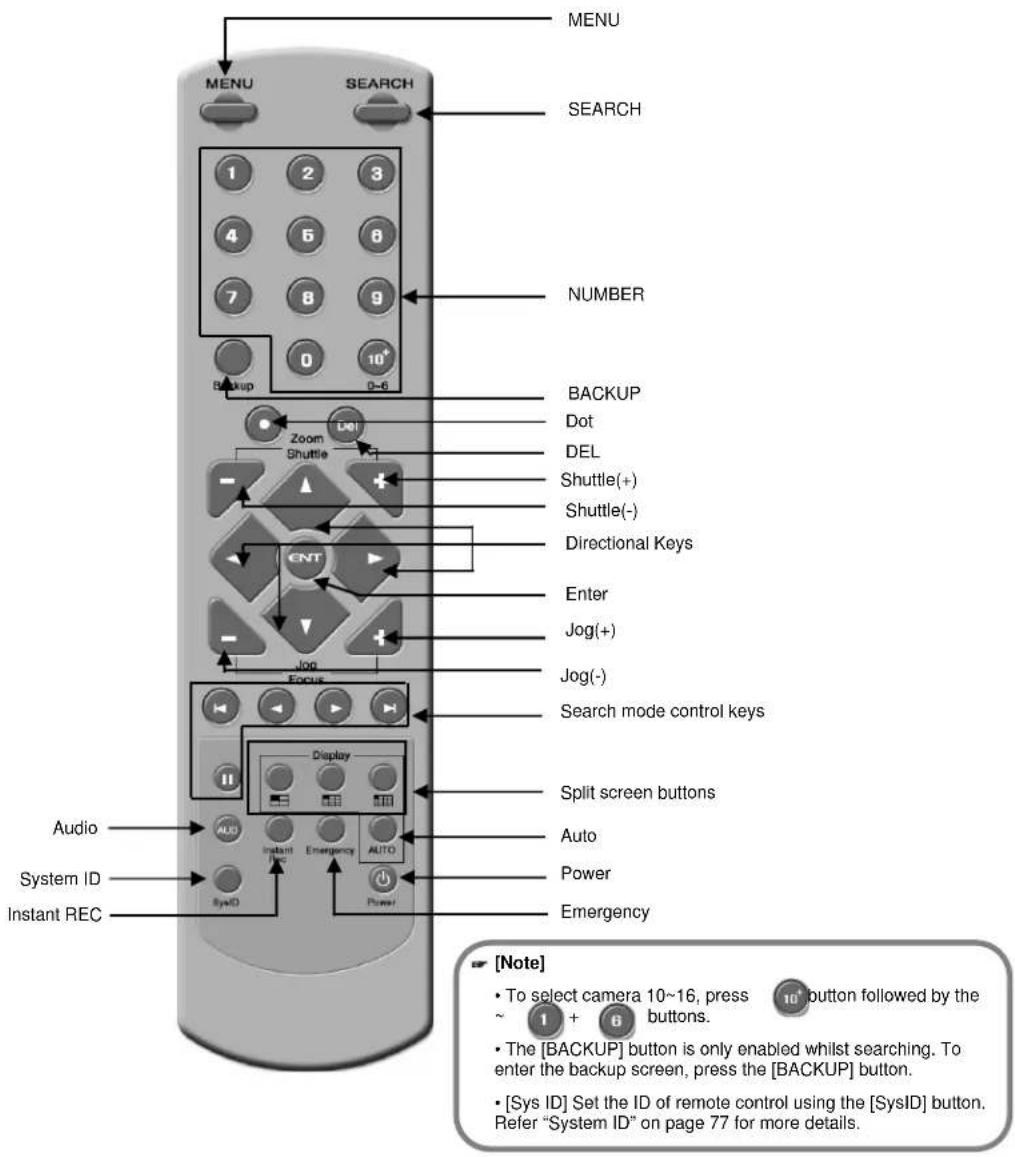
text_image
MENU SEARCH 1 2 3 4 6 8 7 8 9 0 10+ Backup 0-6 NUMBER BACKUP Dot DEL Shuttle(+) Shuttle(-) Directional Keys Enter Jog(+) Jog(-) Search mode control keys Focus Display Split screen buttons Audio System ID Instant REC Auto Power Emergency INT AutoID Instant Emergency AUTO Power2. Installation
2.1 Checking install environment
You should pay attention to the following before you use the product.
- Do not use it outdoor.
- Do not place water or liquid near the connection part or the product.
- Do not impose excessive shock or force.
- Do not pull out the power cord unreasonably.
- Do not disassemble the product on you own.
- Do not exceed the rated input or output voltage range.
- Use the certified power cord only.
- For the product with an input ground, use a power plug with a ground pin.
CHECKING INSTALLATION ENVIRONMENT
Digital Video Recorder (hereinafter referred to "DVR") is a high-tech security equipment that contains a high-capacity HDD and top-notch circuits. High temperature inside or outside of the product may reduce the product life, deteriorate performance (see the Figure 1 below; it explains the correlation between temperature and product life), and lead to a malfunction.
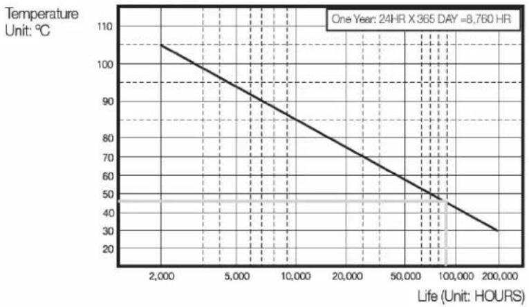
line
| Life (Hours) | Temperature (°C) | | ------------ | ---------------- | | 2,000 | 105 | | 5,000 | 95 | | 10,000 | 85 | | 20,000 | 75 | | 50,000 | 65 | | 100,000 | 55 | | 200,000 | 35 |Figure 1
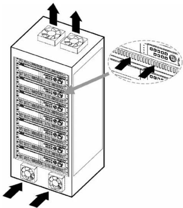
Please keep the following instructions for rack-mounting the DVRs to proceed with the installation.
- The rack on which the DVR is mounted should not be sealed off.
- And it also can allow air circulation through the vent.
- As shown in the Figure 2, we recommend you to heap the product with other DVR s or use rack-mount devices at certain space, or install a vent system to accommodate airflow.
- For forming a natural convection, the air intake hole should be positional at the bottom and the emission at the top.
- We recommend you to install each of the air intake and emission holes with fan motors for sufficient airflow. (The air intake fan should be equipped with a filter to prevent possible inflow of dust and other impurities.)
- As shown in the Figure 1, the temperature inside the rack and around the DVR should maintain between 0 and 45°C.
text_image
Diagram of a server rack with heat exchangers and fan cooling system, showing directional arrows and labeled components.Figure 2
2.2 Pan/Tilt Connection
text_image
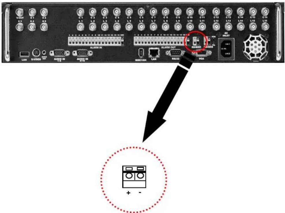
VOUT B1 B2 B3 B4 B5 C1 C2 C3 C4 C5 C6 C7 C8 C9 C10 C11 C12 C13 C14 C15 C16 L1 L2 L3 L4 L5 L6 L7 L8 L9 L10 L11 L12 L13 L14 L15 L16 C 3 4 5 6 7 8 9 10 11 12 13 14 15 16 17 18 19 20 21 ALARM IN LAN S-VIDEO AUDIO OUT AUDIO IN AUDIO IN IEEE104 LAN RS232 VGA RS40SM AC INLET + -RS-485 Signal Cable Connection Port (Used for connecting Speed Dome camera and RX-Receiver)

[Caution]
- Please beware of (+ve) and (-ve) poles of the signal cable when connecting. A wrong connection may cause malfunction of the system.
- If you wish to use an RX-receiver, please contact your dealer beforehand.
2.3 Keyboard Controller
text_image
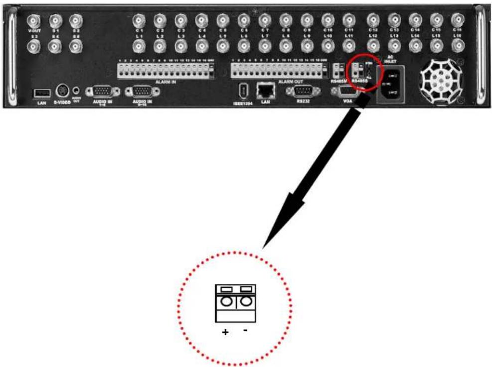
V-OUT B1 B2 B3 B4 B5 C1 C2 C3 C4 C5 C6 C7 C8 C9 C10 C11 C12 C13 C14 C15 C16 L1 L2 L3 L4 L5 L6 L7 L8 L9 L10 L11 L12 L13 L14 L15 L16 C 3 4 5 6 7 8 9 10 11 12 13 14 15 16 17 ALARM IN LAN S-VIDEO AUDIO OUT AUDIO IN AUDIO IN IEEE104 LAN RS232 VDA RS405M RS400S AC INLET + -RS-485 Signal Cable Connection Port (Used for connecting External devices such as keyboard or POS system)

[Caution]
- Please beware of (+ve) and (-ve) poles of the signal cable when connecting. A wrong connection may cause the system to malfunction.
2.4 Connecting LAN/PSTN Communication Lines
2.4.1 LAN and Dedicated Line Connection
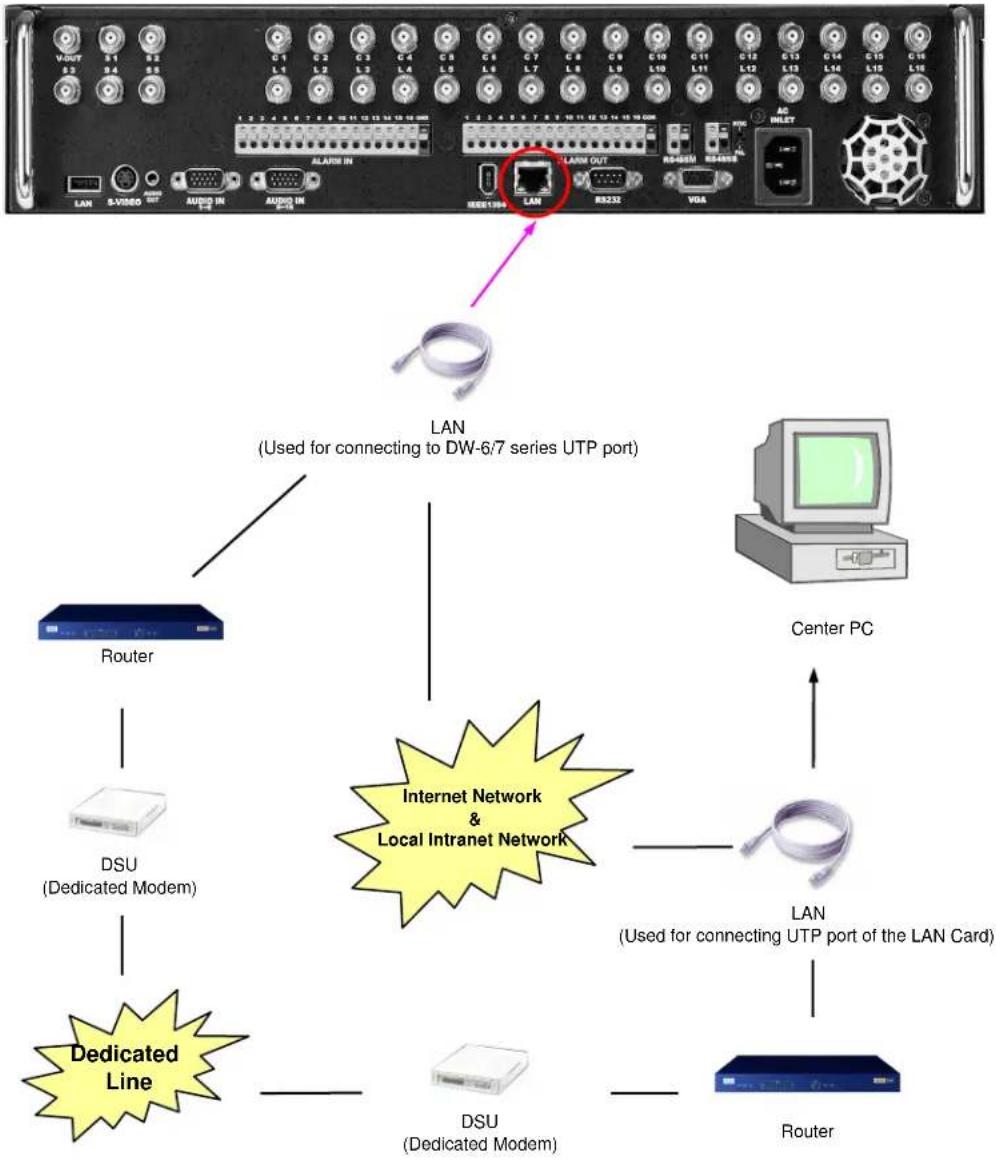
flowchart
graph TD
    A["LAN"] --> B["Router"]
    B --> C["DSU (Dedicated Modem)"]
    C --> D["Dedicated Line"]
    D --> E["DSU (Dedicated Modem)"]
    E --> F["Center PC"]
    F --> G["LAN (Used for connecting UTP port of the LAN Card)"]
    G --> H["Router"]
    I["Internet Network & Local Intranet Network"] --> J["LAN (Used for connecting to DW-6/7 series UTP port)"]
    J --> K["LAN (Used for connecting to DW-6/7 series UTP port)"]
    style A fill:#f9f,stroke:#333
    style F fill:#ccf,stroke:#333
    style G fill:#cfc,stroke:#333
2.4.2 PSTN (telephone line) Connection (options) (Not available in Europe)
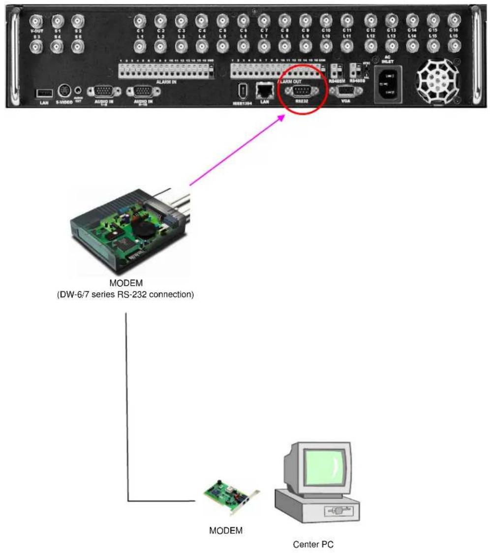
text_image
VOUT S1 S2 S3 S4 S5 C1 C2 C3 C4 C5 C6 C7 C8 C9 C10 C11 C12 C13 C14 C15 C16 L4 L2 L3 L4 L5 L6 L7 L8 L9 L10 L11 L12 L13 L14 L15 L16 ALARM IN RBB1394 LAN ALARM OUT RS232 R3480M RS480B VGA AC HILET LAN S-VIDEO OUT AUDIO IN AUDIO IN MODEM (DW-6/7 series RS-232 connection) MODEM Center PC2.5 Alarm-In Port Connection (Input)
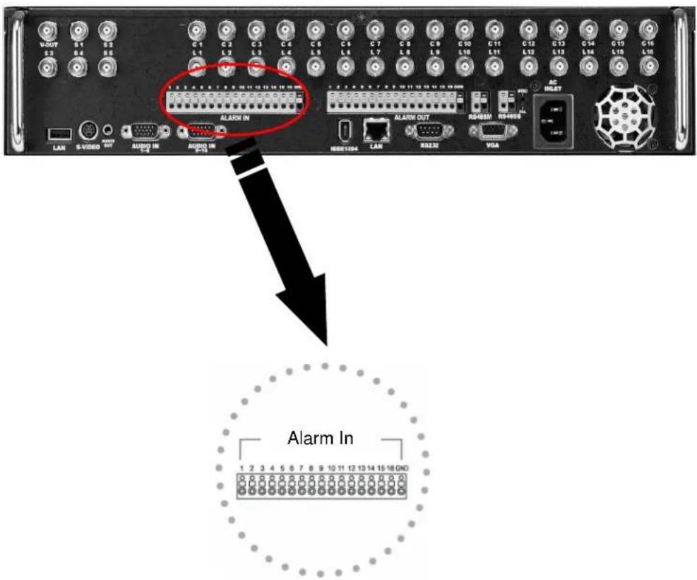
text_image
VOUT S1 S2 S3 S4 S5 C1 C2 C3 C4 C5 C6 C7 C8 C9 C10 C11 C12 C13 C14 C15 C16 L1 L2 L3 L4 L5 L6 L7 L8 L9 L10 L11 L12 L13 L14 L15 L16 ALARM IN ALARM OUT RS493M RS-0003 LAN S-VIDEO OUT AUDIO IN AUDIO IN USB1394 LAN RS232 VGA AC INLET Alarm In 1 2 3 4 5 6 7 8 9 10 11 12 13 14 15 16 GNDConnect one of the two signal lines from the sensor (infrared sensor, magnetic) to COM port, and connect the other signal line to the desired Alarm-In number.

[Caution]
Use a separate adapter to supply power to each sensor.
2.6 Alarm-Out Port Connection (Output)
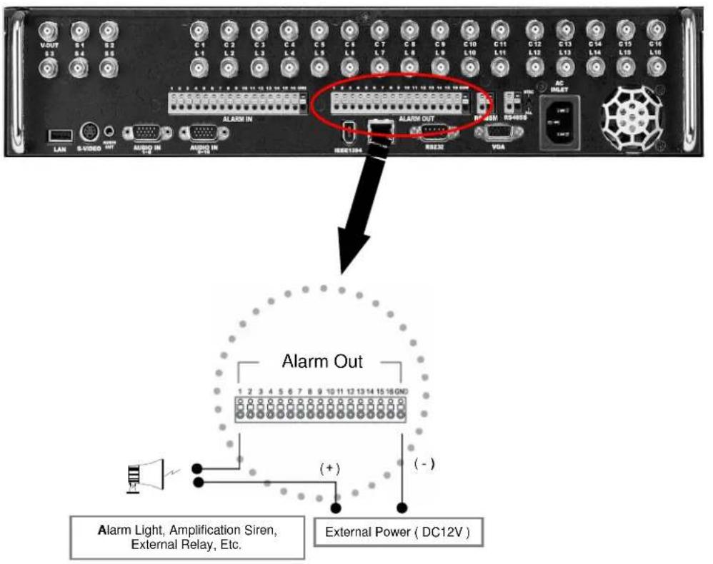
text_image
VOUT S1 S2 S3 S4 S5 C1 C2 C3 C4 C5 C6 C7 C8 C9 C10 C11 C12 C13 C14 G15 G16 L1 L2 L3 L4 L5 L6 L7 L8 L9 L10 L11 L12 L13 L14 L15 L16 L17 ALARM IN ALARM OUT RS-40M RS-4000 LAN S-VIDEO OUT AUDIO IN F-2 AUDIO IN F-1B VGA RS-10A RS-232 RS-40M RS-4000 RS-4000 RS-4000 RS-4000 RS-4000 RS-4000 RS-4000 RS-4000 RS-4000 RS-4000 RS-4000 RS-4000 RS-4000 RS-4000 RS-4000 RF 2.5 2.6 2.7 2.8 2.9 3.0 3.1 3.2 3.3 3.4 3.5 3.6 3.7 3.8 3.9 4.0 4.1 4.2 4.3 4.4 4.5 4.6 4.7 4.8 4.9 5.0 5.1 5.2 5.3 5.4 5.5 5.6 5.7 5.8 5.9 6.0 6.1 6.2 6.3 6.4 6.5 6.6 6.7 6.8 6.9 7.0 7.1 7.2 7.3 7.4 7.5 7.6 7.7 7.8 7.9 8.0 8.1 8.2 8.3 8.4 8.5 8.6 8.7 8.8 8.9 9.0 9.1 9.2 9.3 9.4 9.5 9.6 9.7 9.8 9.9 10.0 Alarm Out 1 2 3 4 5 6 7 8 9 10 11 12 13 14 15 16 GND (+) (-) Alarm Light, Amplification Siren, External Relay, Etc. External Power ( DC12V )- During automatic control of an external sensor, the Alarm-Out output port is "interworked" (the value set in "Set Alarm-In/Alarm-Out" menu) and "COM" port is connected.
- In normal circumstances, the Alarm-Out output is kept in "NO" status.
- When Alarm-Out is triggered, the Alarm-Out output changes to "NC" status.

[Caution]
• The operating voltage should be maximum 12V, 300mA.
- When controlling lights and other devices operated by AC power, use a separate external relay.
3. Live
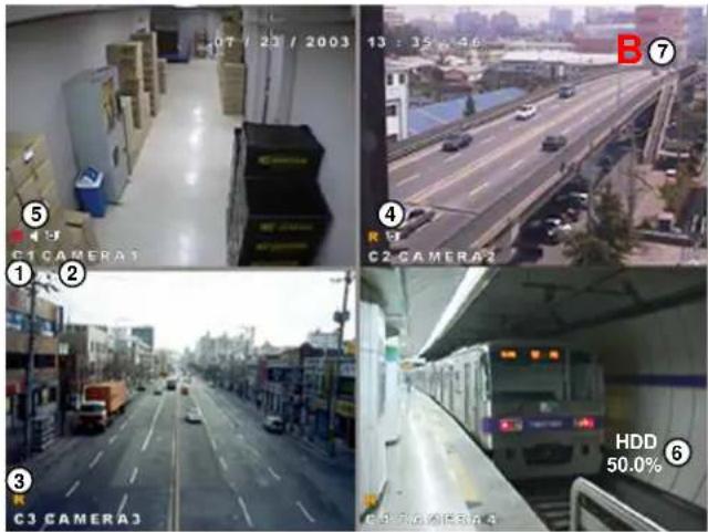
3.1 Screen layout
text_image
07 / 23 / 2003 13 : 35 : 46 ⑤ C1 CAMERA1 ① ② ③ C3 CAMERA3 ④ C2 CAMERA2 B HDD 50.0% ⑥①[Camera number]
- Displays camera number.
②[Camera name]
■ Displays camera name.
③[Recording status]
- Displays camera recording mode enabled.
④[P/T/Z status]
- Displays Pan/Tilt camera status enabled.
⑤ [Audio recording status]
• Shows audio recording enabled.
⑥ [HDD Capacity]
• Display HDD used by percentage.
⑦ [HDD Status]
• Shows when a Bad Sector appears on HDD.
| Available Recording Modes and Screen DisplayRecording Mode | ||
| C: Continuous RecordingM: Motion RecordingS: Alarm In RecordingP: Pre-alarm Recording | No recording | No Display |
| Continuous Recording | Red REC | |
| Motion Recording | Yellow REC | |
| Alarm In Recording | ||
| Motion & Sensor Recording | ||
| Motion & Pre-alarm Recording | ||
| Alarm In & Pre-alarm Recording | ||
| Motion & Alarm In & Pre-alarm Recording | ||
3.2 Enabling full screen and sequence mode
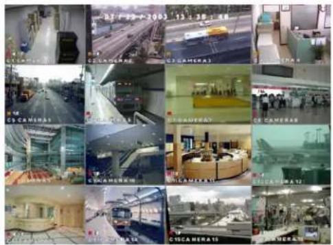
text_image
Grid of surveillance cameras and security camera images with timestamps and labels in Chinese[To Select 16 way split screen]
- Press the 16 way split screen button to view all cameras on one screen (DW-616T/716T).
![Digital Watchdog DW716N-1000 - [To Select 16 way split screen] - 1](/content/2026/05/819966/images/fbf880ecae0b395b1ddd578f62b45c25fd18d99810dec8ea688b6ee859418bfa.jpg)
text_image
Collage of surveillance cameras from different locations including C1 to C9, showing highway, highway, and interior views.[To Select 9 way split screen]
- Press the 9-split screen button to select display of cameras 1-9. Press again to move to next 9 way screen.
![Digital Watchdog DW716N-1000 - [To Select 9 way split screen] - 1](/content/2026/05/819966/images/05fd94523d2ed6439beac5f7d3a3290fabed9f35f7b2df1d395c275783f211c2.jpg)
text_image
07 / 33 / 2003 13 : 38 : 46 G1 CAMERA[To Select Quad screen]
![Digital Watchdog DW716N-1000 - [To Select Quad screen] - 1](/content/2026/05/819966/images/24ae8f5804b585d798ca9573ef2054b7c9ed11dcaf568f8f7cfcb389951a06e1.jpg)
Press the 4-split screen button to select quad display of cameras 1-4. Press again to move to next quad screen.
[To Select Full Screen mode]
Press any key 1\~16 on the system to enlarge that camera channel and view in full screen.
[Sequence]
- When full screen is selected, press the Auto key to view all camera channels in sequence. The system will also sequence between quad and 9 way displays. (OSD/Dwell Time for details on changing Auto option).
3.3 POP-UP MENU
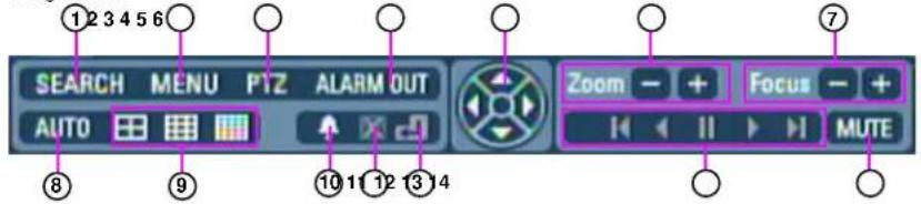
- You can use this menu by pressing mouse-right button. Items shown on the pop-up menu are identical with buttons at system's front panel. The benefit of this menu is that user can operate DVR system by simply using mouse.
text_image
SEARCH MENU PTZ ALARM OUT AUTO Zoom - + Focus - + MUTE ① 2 3 4 5 6 ⑦ ⑧ ⑨ ⑩ 11 12 13 14| FeaturesNamesNo. | |||
| 1 |  | button | • It start search mode. Search |
| 2 |  | Menu button | • It switches system to setup mode.• Users can use this menu to move from lower level menu to upper level menu or when they exit from system setup mode. |
| 3 |  | • Button to enter Pan/Tilt control menu.PTZ button | |
| 4 | ALARM OUT | Alarm Out button | • Click on "ALARM OUT" to go to Alarm Out menu.• When using front panel, press Enter button. |
| 5 |  | Direction button | • This button controls PTZ directions at PTZ mode.• If user press Enter button, the pop-up menu will disappear. |
| 6 |  | Zoom In/Out | • Zoom In/Out any supported Pan/Tilt or Speed Dome type camera. |
| 7 |  | Focus In/Out | • Adjusts focus of the camera lens. (This function is not supported on any auto focus) |
| 8 |  | Auto button | • To start sequencing display mode, select single channel screen.• Press auto display icon to get auto rotation screen. Click to view live image in single channel mode. |
| 9 |  | Spit Screen button | • You can get 4/9/16 channel display screen with clicking the icon by mouse or pressing the front panel key. |
| 10 | button | • It start event search mode.Event Search | |
| 11 | cancel button | • It cancel backup process.Backup | |
| 12 | Search return button | • It switches to initial search screen during playing video images.• It start search mode. Playback button | |
| MUTE | Mute button | • Adjust select MUTE if you do not wish to listen to live audio. | |
3.4 Pan/Tilt Camera
3.4.1 Switching to Pan/Tilt control mode
natural_image
Interior view of a modern office or gas station with cubicles and desks (no visible text or symbols)[Pan/Tilt camera control]
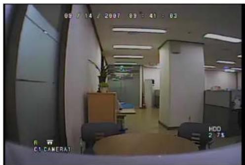
- Select the camera channel connected to the P/T/Z camera by using the mouse or camera number keys on the front panel. This will display the channel in full screen mode.
- Once the channel is enlarged, press [Enter] to access [P/T/Z control] mode. Pan/Tilt controls may differ depending on the connected camera model.
![Digital Watchdog DW716N-1000 - [Pan/Tilt camera control] - 1](/content/2026/05/819966/images/645750124be50bf1dfbd4a30734fb172db2f01a966844cfbb8b9fe124c88a337.jpg)
![Digital Watchdog DW716N-1000 - [Pan/Tilt camera control] - 2](/content/2026/05/819966/images/413c46f95cb641ef0aaab5a8a00fdc1bf9aea7a4ae4bb211f836c87fecfcfbbb.jpg)
text_image
ZC-S0622JF Auto Pin Reset Delete AT-Square Checked Position 1 2 3 4 5 6 7 8 9 10 Close Mode OK...[Exiting P/T/Z control mode]
- When you have finished with this screen, click [OK] button by mouse or press MENU on the front panel to return to Surveillance mode.
3.4.2 Pan/Tilt Camera Control
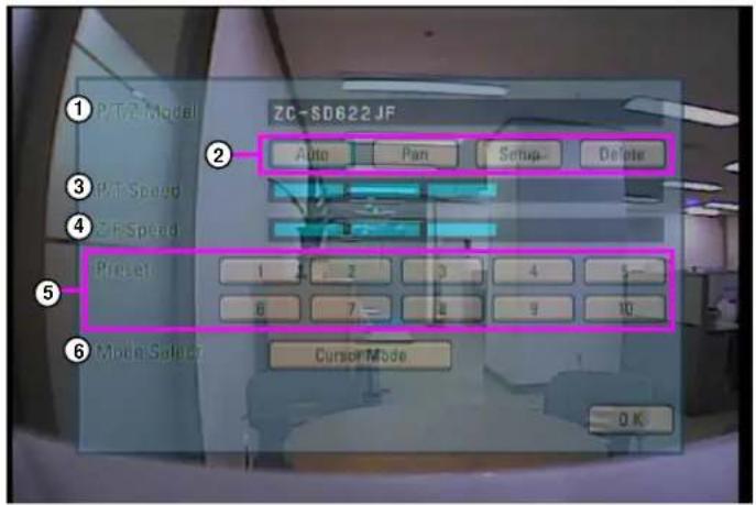
In P/T/Z menu, you can switch the P/T/Z camera controls to manual control, as well as changing Zoom, Focus, and Auto Pan settings.
text_image
P/TZ-Model ZC-SD622 JF Auto Pan Setup Delete P/T Speed ZC-RSpeed Preset 1 2 3 4 5 6 7 8 9 10 Cursor Mode OK[Figure 4-3. P/T/Z menu]
① [P/T/Z model]
- Displays the P/T/Z camera model.
② [P/T/Z function buttons]
- You can enable or disable P/T/Z camera functions by selecting the options you wish to use by using the mouse or the [Directional] and [Enter] key on the front panel.
- Some functions may differ depending on the P/T/Z camera model you are using.
③ [P/T speed]
- Use the directional keys on the system to set the speed of the movement of the Speed Dome camera when it is to be controlled manually.
- P/T Speed only applies if you are using a Speed Dome camera.
④ [Z/F speed]
- Use the jog/shuttle on the system to set the camera zoom/focus rate.
- Z/F Speed only applies if you are using a Speed Dome camera.
⑤ [Preset]
- If you have a Speed Dome camera configured with presets, selection of a numbered button will move the camera to that preset position (see [Mode Select] below).
- Preset selection only applies if you are using a Speed Dome camera.
⑥ [Mode select]
- Mode button is used to set the Speed Dome camera to a preset position.
- Select the [Cursor Mode] button using the [Directional] keys, then press [Enter] to change to [P/T Mode].
- To set the position of the Speed Dome camera to a preset, change the [Cursor Mode] to [P/T Mode], then move the camera position using the directional keys. Once the camera is in the desired position, change the [P/T Mode] back into [Cursor Mode].
3.4.3 Supported Pan/Tilt Camera List
| No. | Manufacture | Modal Name | P/T | Speed | ZoomP/T | Focus | Speed | PreseIZ/F | Manual Control and other function | BPSIRIS | |
| 1 | LG | LG MULTIX | YES | YES | YES | YES | YES | YES | YES | NO | 9800 |
| 240NO YESYESYESYESYESYESPELCO-5D | |||||||||||
| 3 | DONG-YANG | DRX-501A | YES | YES | YES | YES | NO | NO | YES | NO | 2400 |
| 4 | HONEYWELL | GC-755 | NO | NO | YES | YES | YES | NO | NO | NO | 9800 |
| 5 | TOA | ZG-SDB22JF | YES | YES | YES | YES | YES | YES | YES | NO | 19200 |
| SAMSUNG6 | Samsung PTZ carriers | YESYESYESYESYES | |||||||||
| 960NO YESYESNOYESYESYESESTechonSAMSUNG7 | |||||||||||
| 240NO YESNONOYESYESNOYESKRE-303 ORION8 | |||||||||||
| 960NO YESNONOYESYESNOYESKRE 30SORIONS |
3.5 ALARM OUT – Manual Control
3.5.1 Switching to Alarm Out Mode
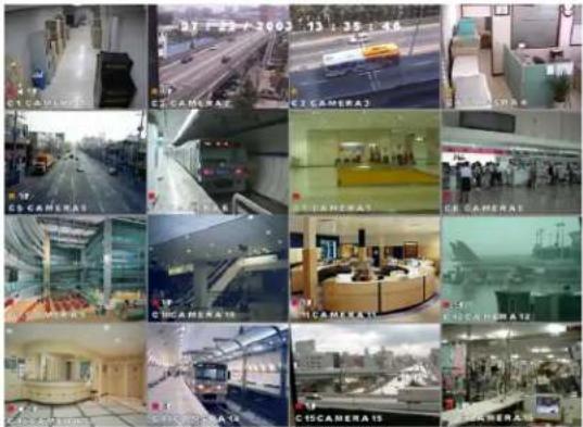
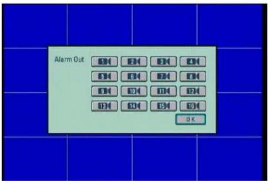
If you wish to use the control devices manually, select the 16-splitscreen mode in Surveillance mode, then press Enter key. You will then be able to select the control devices you wish to use manually.
text_image
27 - 22 - 2003 13 - 35 - 16 CSCAMERA CSCAMERA CSC CAMERA3 CSC CAMERA CSC CAMERA4 CSC CAMERA18 CSC CAMERA19 CSC CAMERA12 CSC CAMERA14 CSC CAMERA15 CSC CAMERA16 CSC CAMERA17 CSC CAMERA18 CSC CAMERA19 CSC CAMERA12
text_image
Alarm Out OK[Alarm Out]
- Use the mouse or the directional keys and Enter key to select the control device numbers you wish to control manually.
[Exiting Alarm Out mode]
- Press [Enter] button to return to Surveillance mode.
4. System setup
4. System Setup
4.1 Accessing Setup mode
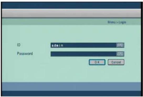
To go to the system setup screen, click the [MENU] button on the front of the system. The login window will then be displayed, enabling the inputting of login ID and password as shown below:
text_image
Menu > Login ID admin Password OK Cancel- Click the [Input] button to enter the desired login ID and password. (The admin account initially has no password).
- If you forget your password, you will not be able to access Setup mode, or change your password. We strongly recommend that you either write down your password and keep it safe or use a password that you are sure to remember.
4.2 Recording menu
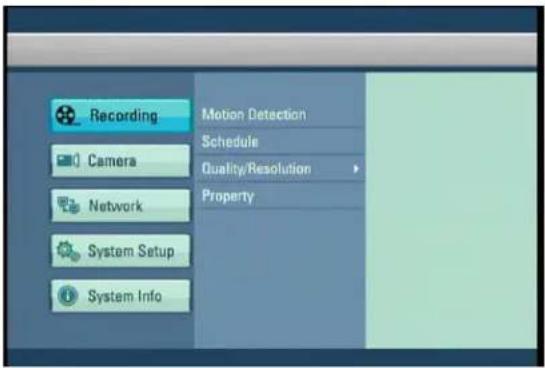
• The details of the recording menu are as follows:
text_image
Recording Motion Detection Schedule Quality/Resolution Property Camera Network System Setup System Info4.2.1 Motion detection
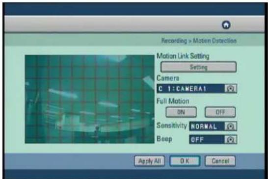
- Set the motion detection area, sensitivity and alarm for each camera video. Press the [Enter] button after moving the cursor on the camera to be set.
text_image
Recording > Motion Detection Motion Link Setting Setting Camera C 1:CAMERA1 Full Motion ON OFF Sensitivity NORMAL Beep OFF Apply All OK Cancel[Motion Link Setting]
- You can set a motion-link recording for each camera.
- When the camera detects movement in the motion-detection area, the linked camera will begin recording as well, regardless of its recording schedule.
- To use Motion-link recording, the camera detecting the movement must be set to Motion-Detection recording in the schedule. If the camera's schedule is set to Continuous Recording, Motion Link will be disabled.
- In Surveillance mode, when the camera detects movement in its motion-detection area, the linked camera channel will flash 'REC' and begin recording.
- To access Motion Link Setting, use the mouse or the directional keys to select [Setting].
![Digital Watchdog DW716N-1000 - [Motion Link Setting] - 1](/content/2026/05/819966/images/f928c13f52a0e77a0fea6539f17be3208ffd2e5e183ba8580167bdce2996d0e4.jpg)
text_image
Recording > Motion Detection > Motion Link Setting Motion Camera C 1: CAMERA1 Link Camera OK Cancel[Motion Camera]
- Select the camera that will detect the movement in its motion-detection area by using the mouse wheel or the jog/shuttle on the system.
[Link Camera]
- Select the cameras that will be linked to the [Motion Camera] by using the mouse or the directional keys. You can link multiple cameras to the selected [Motion Camera].
[Camera]
- Use the jog/shuttle on the system to select other cameras for set up.
[Full Motion]
- To set the whole channel screen to motion-detection area, switch the [Full Motion] option to "ON". To cancel the whole screen from motion-detection area, switch the option to "OFF".
[Sensitivity]
- You can set the motion-detection sensitivity of each camera to "LOWEST", "LOW", "NORMAL", "HIGH" or "HIGHEST".
[Beep]
- To hear a 'beep' warning sound when the system detects movement in motion-detection area, set the [Beep] option to "ON". To hear no warning sound, set the option to "OFF"
[Apply All]
- Click the [Apply All] button to apply the current camera setting to all cameras.
4.2.2 Schedule
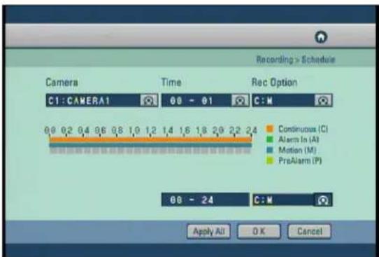
- Set the recording type for each camera over a 24 hour period.
text_image
Recording > Schedule Camera Time Rec Option C1: CAMERA1 08 - 01 C:M Continuous (C) Alarm In (A) Motion (M) PreAlarm (P) 08 - 24 C:M Apply All OK Cancel[Camera]
- Use the mouse wheel or the Jog/Shuttle to select the camera to change its schedule.
[Time]
- Change the recording time in hourly intervals
- Use the mouse to toggle the time or use the jog and shuttle dials on the front of the DVR
[REC Option]
- You can select a recording mode for the selected camera by using the mouse or directional keys to highlight the type of recording you wish to set.
• Available recording modes are listed on the table below. You can set none recording as an option.
[24 Hour setting]
- This setting applies the recording type to a camera for the whole 24 hour period.
- Select the type of recording using the mouse or jog and shuttle to toggle between the settings.
00 - 24
[Apply All]
- Click the [Apply All] button to apply the current camera setting to all cameras.
| Available Recording ModesRecording | Schedule Setup Display | |
| C: Continuous RecordingM: Motion RecordingA: Alarm In RecordingP: Pre-alarm Recording | No RecordingContinuous RecordingMotion RecordingAlarm In RecordingMotion & Sensor RecordingMotion & Pre-alarm RecordingAlarm In & Pre-alarm RecordingMotion & Alarm In & Pre-alarm Recording | NoneCMAA: AM: PM: PM: PM: P |
4.2.3 Quality/Resolution
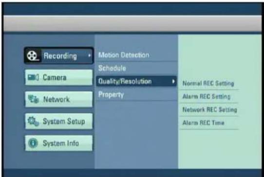
• The details of the Quality/Resolution menu are as follows:
text_image
Recording Motion Detection Schedule Quality/Resolution Property Camera Network System Setup System Info Normal REC Setting Alarm REC Setting Network REC Setting Alarm REC Time4.2.3.1 Normal REC Setting
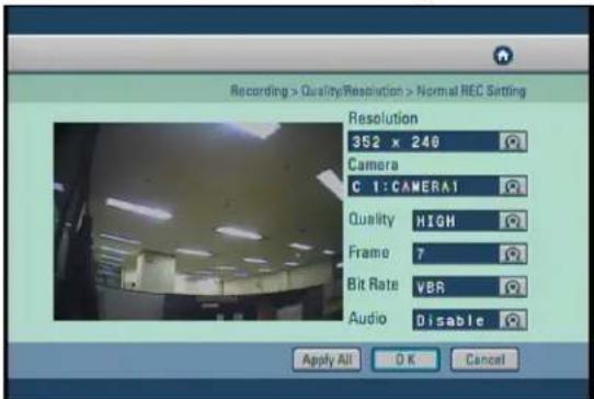
- You can set the recorded mode values for normal DVR recording.
text_image
Recording > Quality/Resolution > Normal NEC Setting Resolution 352 x 240 Camera C 1:CAMERA1 Quality HIGH Frame 7 Bit Rate VBR Audio Disable Apply All OK Cancel[Resolution]
- Set the screen size for recording.
| Source | CIFHalf D1Full D1Video | ||
| 352x240704x240704x480NTSC | |||
| 352x288704x288704x576PAL |
[Camera]
- Select which channel to set up.
[Quality]
- Select the recording video quality. Set between the option of LOW, NORMAL, HIGH and BEST.
[Frame]
- Select the number of frames for recording. The number of frames refers to the number of screens recorded per second (fps).
[Bit Rate]
- Select bit rate to fit network bandwidth.
- VBR transfer high quality image to remote software, but network transfer speed can be slow.
- CBR transfer middle quality image to remote software, but network transfer speed can be fast.
[Audio]
- To recording sound with the selected camera. Select whether to save audio data or not for each camera.
[Apply All]
- Click the [Apply All] button to apply the current camera setting to all camera.
[Note]
- Recording frame rate may very depending on the number of installed camera or system load.
4.2.3.2 Alarm REC Setting
- You can set the DVR recording mode values when a Alarm happens (Alarm In, Motion detection, Instant recording).
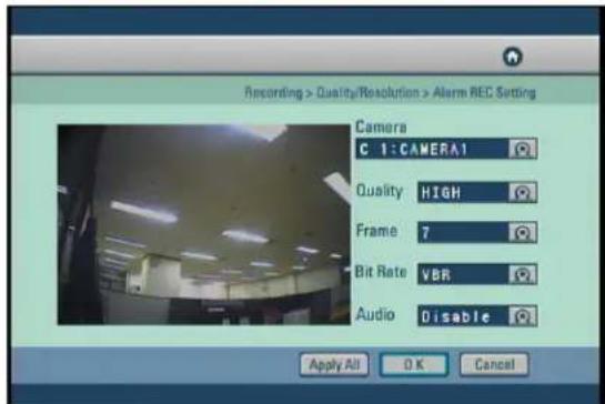
text_image
Recording > Quality/Resolution > Alarm REC Setting Camera C 1: CAMERA1 Quality HIGH Frame 7 Bit Rate VBR Audio Disable Apply All OK Cancel[Camera]
- Select which channel to set up.
[Quality]
- Select the recording video quality. Set between the option of LOW, NORMAL, HIGH and BEST.
[Frame]
- Select the number of frames for recording, The number of frames refers to the number of screens recorded per second (fps).
[Bit Rate]
- Select bit rate to fit network bandwidth.
- VBR transfer high quality image to remote software, but network transfer speed can be slow.
- CBR transfer middle quality image to remote software, but network transfer speed can be fast.
[Audio]
- To recording sound with the selected camera. Select whether to save audio data or not for each camera.
[Apply All]
- Click the [Apply All] button to apply the current camera setting to all camera.
4.2.3.3 Network REC Setting
- Set image values for network transmission.
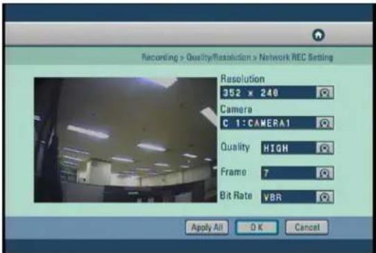
text_image
Recording > Quality/Resolution > Network REC Setting Resolution 352 x 240 Camera C 1: CAMERA1 Quality HIGH Frame 7 Bit Rate VBR Apply All OK Cancel[Resolution]
- Set image size transmitting.
| Source | CIFHalf D1Full D1Video | ||
| 352x240704x240704x480NTSC | |||
| 352x288704x288704x576PAL |
[Camera]
- Select which channel to setup.
- Select the image transmission quality. select between the options LOW, NORMAL, HIGH, BEST.
- Select the number of frames to transmit through network. This will be the number of frames transmitted for every one second.
[Quality]
[Frame]
[Bit Rate]
- Select bit rate to fit network bandwidth.
- VBR transfer high quality image to remote software, but network transfer speed can be slow.
- CBR transfer middle quality image to remote software, but network transfer speed can be fast.
[Apply All]
- Click the [Apply All] button to apply the current camera setting to all camera.
4.2.3.4 Alarm REC Time
- Set Pre-Alarm, Post-Alarm and whether buzzer occur or not on instant recording.
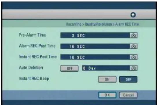
text_image
Recording > Quality/Resolution > Alarm REC Time Pre-Alarm Time 3 SEC Alarm REC Post Time 10 SEC Instant REC Post Time 10 SEC Auto Deletion OFF 9 Day Instant REC Beep ON OFF OK Cancel[Pre-Alarm Time]
- Setup Pre-Alarm recording start work-time.
[Alarm REC Post Time]
- Setup Post Alarm (Alarm In, Motion detection) recording time.
[Instant REC Post Time]
- Setup Instant Recording Time.
[Auto Deletion]
- You can setup the storage period of the recoded data, where by the stored data will be automatically deleted from the hard disk after the specified number of days has passed.
• The default setup is [OFF].
[Instant REC Beep]
- Setup Beep sound working-time.
4.2.4 Property
- Change the color, brightness and contrast for each camera.
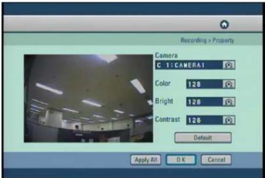
text_image
Recording > Property Camera C 1:CAMERA1 Color 128 Bright 128 Contrast 128 Default Apply All OK Cancel[Camera]
- Select which channel to set up.
[Color/Bright/Contrast]
- You can set the color, brightness and contrast of the selected camera.
- The adjustment can be made from '0' to '255' using the jog/shuttle or mouse wheel.
[Default]
- Select [Default] button to set the color, brightness and contrast to their default value.
[Apply All]
- Click the [Apply All] button to apply the current camera setting to all camera.
4.3 Camera menu
• The details of the camera menu are as follows:
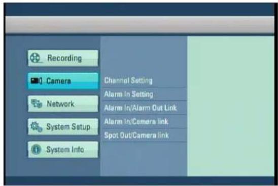
text_image
Recording Camera Network System Setup System Info Channel Setting Alarm In Setting Alarm In/Alarm Out Link Alarm In/Camera link Spot Out/Camera link4.3.1 Channel Setting
- Set camera status and name, add PTZ protocol to camera.
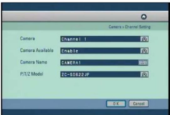
text_image
Camera > Channel Setting Camera Channel 1 Camera Available Enable Camera Name CAMERA1 P/T/Z Model ZC-SD622JF OK Cancel[Camera]
- Select the channel to set up the camera.
[Camera Available]
- Set the use of the selected camera between Enable/Disable and Secure using the mouse scroll wheel or jog/shuttle.
[Camera Name]
- The camera name of the selected channel can be set. A virtual keyboard appears if you press the Enter button.
- Characters can be input one by moving the cursor. You can input up to 10 characters. If you press "Shift", you can input the uppercase letters and number keys.
![Digital Watchdog DW716N-1000 - [Camera Name] - 1](/content/2026/05/819966/images/19166f89c2d1c7ec3e0a8026f48819bc3e75c42a514eebd081055759109aa223.jpg)
text_image
Camera > Channel Setting Camera Name CAMERA1 1 2 3 4 5 ~6 7 *8 9 10 o q w e r t y u i o p A a s o d f g h j k l ← z z x c v b n m - . / : _ Shift OK Cancel[P/T/Z Model]
- Lets you select P/T/Z on the selected camera channel.
4.3.2 Alarm in Setting
- Configure Alarm In type Normally Open and Normally Close setting and beep option.
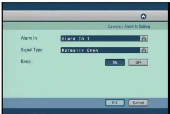
text_image
Camera > Alarm In Setting Alarm In Alarm In 1 Signal Type Normally Open Beep ON OFF OK Cancel[Alarm In]
- Select the Alarm In number for configuration.
[Signal Type]
- The Alarm In type can be set to "Normally Open", or "Normally Close".
- Normally Closed type = If the door/object with the Alarm In installed is not closed, the Alarm In will trigger.
- Normally Open Type = If the door/object with the Alarm In installed is not opened, the Alarm In will trigger
[Beep]
- When Alarm In are triggered, the system will produce "Beep" alarm sound through its internal speakers. Select "ON" to enable alarm, and select "OFF" to disable it.
4.3.3 Alarm In Out Link
- Link Alarm In and Alarm Out devices, and activation time.
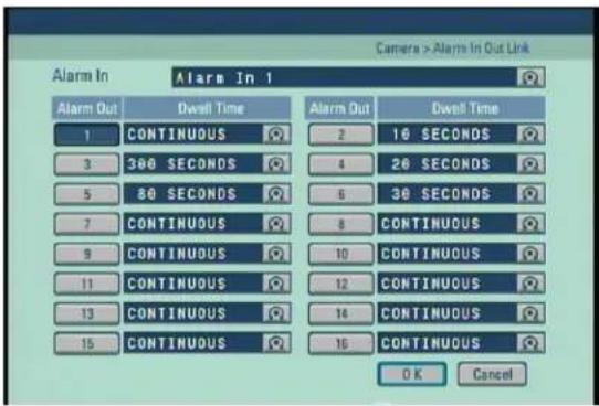
text_image
Camera > Alarm In Out Link Alarm In Alarm In 1 Alarm Out Dwell Time Alarm Out Dwell Time 1 CONTINUOUS 2 10 SECONDS 3 300 SECONDS 4 20 SECONDS 5 80 SECONDS 6 30 SECONDS 7 CONTINUOUS 8 CONTINUOUS 9 CONTINUOUS 10 CONTINUOUS 11 CONTINUOUS 12 CONTINUOUS 13 CONTINUOUS 14 CONTINUOUS 15 CONTINUOUS 16 CONTINUOUS OK Cancel[Alarm In]
- Select the Alarm In number for configuration.
[Alarm Out]
- You can link a Alarm In with Alarm Out devices. When a Alarm In is triggered, the lined Alarm Out device(s) will automatically activate.
[Dewll Time]
- You can set how long the Alarm Out devices will stay activated. The value can be changed in 10 seconds segments up to maximum of 300 seconds.
- Set up continuous to keep Alarm Out put period.
![Digital Watchdog DW716N-1000 - [Dewll Time] - 1](/content/2026/05/819966/images/addf4c766f1e48136b48daa0dce6a45bfb51aeadc966e9413f3cc3a2c688a455.jpg)
- Alarm In function means alarm control event. For example siren, emergency lamp.
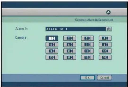
4.3.4 Alarm In Camera link
- Link the Alarm In and camera recording.
text_image
Camera > Alarm In Camera Link Alarm In Alarm In 1 Camera OK Cancel[Alarm In]
- Select the Alarm In number for configuration.
[Camera]
- Choose the cameras you wish to link with the selected Alarm In.
- When the Alarm In is triggered, the linked camera(s) will automatically begin recording.
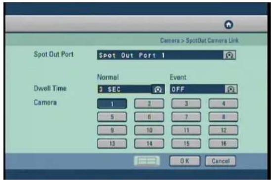
4.3.5 Spot Out Camera Link
- When you have spot monitors, the Spot Out channel can be used for monitoring a specific channel on a dedicated monitor.
text_image
Camera > SpotOut Camera Link Spot Out Port Spot Out Port 1 Dwell Time Normal Event 3 SEC OFF 1 2 3 4 5 6 7 8 9 10 11 12 13 14 15 16 OK Cancel[Spot Out Port]
- Select the spot output port to connect to the selected camera.
[Normal Dwell Time]
- 1\~60 Seconds: Its sets the display duration of the current channel until the next channel is displayed.
[Event Dwell Time]
- Sets whether or not to run the Event Monitoring function for the Spot Out channel. It can be set to any of off, 30 seconds, and Continue.
[Camera]
- Selecting with cameras to view on spot monitor output.
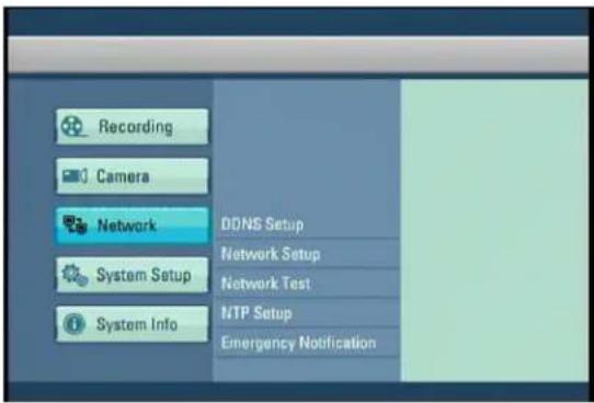
4.4 Network
• The details of the network menu are as follows :
text_image
Recording Camera Network System Setup System Info DDNS Setup Network Setup Network Test MTP Setup Emergency Notification4.4.1 DDNS Setup
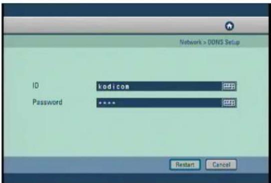
- DDNS Setup function allows you to use the dynamic IP address connected to the system as if it is a fixed IP Address.
text_image
Network > DOSNS Setup ID kodicom Password **** Restart Cancel[ID]
- Input the user ID for the DDNS account. (DDNS accounts can be registered as this website www.dnsdvr.com)
[Password]
- Input the Password for the DDNS account
[Restart]
- Refreshes the DDNS connection, should be used when entering a new or changing the DDNS account.
[Note]
- If you have a public DDNS address (dnsdvr.com), It may take 30 to 60 seconds until the IP address of the host name (URL) can be updated on the DNS website.
4.4.2 Network Setup
- Input Network connection details for remote access.
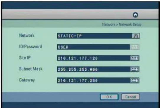
text_image
Network > Network Setup Network STATIC-IP ID/Password USER Site IP 210.121.177.120 Subnet Mask 255.255.255.000 Gateway 210.121.177.250 OK Cancel[Network]
- The system supports network connection using Static IP, as well as DHCP, ADSL connections. The other option is to select no network when not networking the DVR.
[ID/Password]
- You can manually enter the ID/Password when ADSL is selected.
- When the main system is connected to the ADSL network, you need to enter user ID and password provided by the ADSL carrier. The user ID and Password may be entered by using the virtual keyboard.
![Digital Watchdog DW716N-1000 - [ID/Password] - 1](/content/2026/05/819966/images/2ab825114dbed57e969ead877e4108b154a6388dc3849ac0883e66644e18a064.jpg)
text_image
Network > Network Setup ID Password USER Shift OK Cancel[Site IP]
- Sets the IP address for the system to be connected to the network, if the connection mode is set to STATIC-IP, the user needs to enter the IP address directly in this location.
- If the connection mode is either by DHCP or ADSL, the IP address is provided by the DHCP server or ADSL carrier and will be automatically set. If DHCP or ADSL connection attempt fails, 000.000.000.000 will be displayed in the network management screen. In this case, turn off the system power and wait for a while then turn back on for reconnection.
[Subnet Mask]
- Input the subnet mask address for the system.
[Gateway]
- Input the gateway address for the system.
4.4.3 Network Test
- Check the DVR is connected to the network.
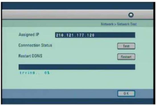
text_image
Network > Network Test Assigned IP 210.121.177.126 Connection Status Test Restart DDNS Restart trying 0% OK[Assigned IP]
- Assigned IP display the system's IP address used for remote backup and remote monitoring.
[Connection Status]
- Connection Status indicates whether the current assigned IP address can be used to connect to the internet. If it is possible, the system will display "OK" in the progress bar. Otherwise, the system will display "Failed".
[Restart DDNS]
- Receive a new DDNS authentication.
- DDNS authentication allows you to use Internet using the IP address (ADSL, DHCP).
4.4.4 NTP Setup
- Synchronize time to a server with the NTP(Network Time Protocol).

text_image
Network > NTP Setup Primary Address pool.ntp.org Secondary Address asia.pool.ntp.org Connection Status NTP Enable Test trying... 0% OK Cancel[Primary Address] & [Secondary Address]
- Sets the NTP server address.
[Connection Status]
- To check the connection status with the NTP server in [Primary Address] or [Secondary Address] field, click on "Test" button.
- When communication is possible with the NTP server, "Success" is displayed on the progress bar. Otherwise, "Fail" is displayed.
[NTP Enable]
- The operator can decide whether to use NTP feature or not. To use the NTP feature, click on [NTP Eanble] button.
[Note]
- The operator cannot change the time in the Setup menu but can set the Time Zone while the NTP feature is enabled.
- The NTP server and the system are synchronized every hour.
- In case that the system time of the DVR is later than the current standard time provided by the NTP, and the system time is reset by the NTP, then the recording is stopped until the system time passes the prior system time before the reset in order to prevent overwrite of the previous record. That is recording will start again after the newly set system time passes the last old system time.
* NTP Server List
| ISO | Area | NTP Server Address |
| Worldwide | pool.ntp.org | |
| Asia | Asia.pool.ntp.org | |
| Europe | Europe.pool.ntp.org | |
| North America | North-america.pool.ntp.org | |
| Oceania | Oceania.pool.ntp.org | |
| South America | South-america.pool.ntp.org | |
| at.pool.ntp.orgAustriaAT | ||
| au.pool.ntp.orgAustraliaAU | ||
| BBe.pool.ntp.orgBelgium | ||
| CBe.pool.ntp.orgCanada | ||
| Cth.pool.ntp.orgSwitzerland | ||
| CL | Chile | cl.pool.ntp.org |
| DBe.pool.ntp.orgGermany | ||
| DBe pool.ntp.orgDenmark | ||
| EBe pool.ntp.orgSpain | ||
| FI | Finland | fi.pool.ntp.org |
| FranceFR | fr.pool.ntp.org | |
| gt.pool.ntp.orgGuatemalaGT | ||
| ie.pool.ntp.orgIrelandIE | ||
| IT | Italy | it.pool.ntp.org |
| JFp.pool.ntp.orgJapan | ||
| MfP pool.ntp.orgMexico | ||
| my.pool.ntp.orgMalaysiaMY | ||
| nl.pool.ntp.orgNetherlandsNL | ||
| no.pool.ntp.orgNorwayNO | ||
| nz.pool.ntp.orgNew ZealandNZ | ||
| ph.pool.ntp.orgPhilippinesPH | ||
| pl.pool.ntp.orgPolandPL | ||
| pt.pool.ntp.orgPortugalPT | ||
| ru.pool.ntp.orgRussiaRU | ||
| SBe pool.ntp.orgSweden | ||
| us.pool.ntp.orgUSAUS | ||
4.4.5 Emergency Notification
- When an emergency Alarm in event has occurred, the Emergency Notification either delivers the emergency message and video to the IP address with the CMS or transmits an e-mail to a designated e-mail address.
- Press the "CMS" button to set the Emergency Notification by CMS.
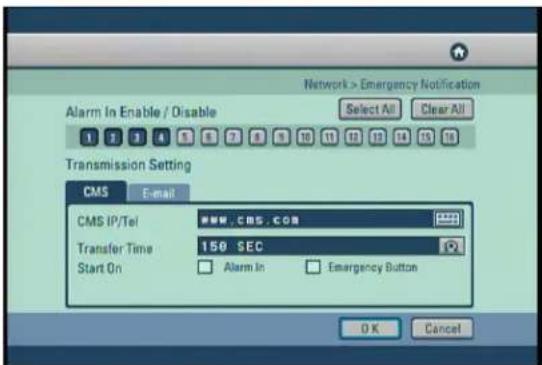
text_image
Network > Emergency Notification Alarm In Enable / Disable Select All Clear All Transmission Setting CMS E-mail CMS IP/Tel 150 SEC Transfer Time Start On Alarm In Emergency Button OK Cancel[Alarm In Enable/Disable]
- You can select/unselect the Alarm In to be used as an emergency Alarm In.
- In circumstance that a signal is generated in the emergency Alarm In, the images of the linked camera are transmitted to a remote location address.
[CMS IP/Tel]
- Enter the IP address that CMS is executed. The following input screen will appear if the "Enter" button is pressed.
![Digital Watchdog DW716N-1000 - [CMS IP/Tel] - 1](/content/2026/05/819966/images/a36b262123176053c6d53482cbae7a8c54fe2100d659520c6f56ff4d95677a95.jpg)
text_image
Network > Emergency Notification CMS IP/Tel CMS :CMS :COM 1 2 3 4 5 6 7 8 9 0 0 q w w e e r t t y y u i i o r p A a s s d f f g h h j j k l i ← z z x x c c y v b n m m - / : _ Shift OK Cancel[Transfer Time]
- Set the time that a emergency message is transmitted.
• Transmit in a until of 30, 60, 90, 120 or 150 seconds.
[Start On]
- To enable the Emergency Notification feature by Alarm In event, selected the "Alarm In" event field.
- To enable the Emergency Notification feature using the [Emergency] button on the front panel of the system, select the "Emergency Button" event field.
- Click the "E-mail" button to display the email transmission settings.
- To receive emergency notification via e-mail, set the SMTP address, sender's e-mail address, recipient's mail address.
![Digital Watchdog DW716N-1000 - [Start On] - 1](/content/2026/05/819966/images/aa56dfe14f04951d92e9d0e66306bf91566ed9594c3345fa3338fd4534dd0be0.jpg)
text_image
Network > Emergency Notification Alarm In Enable / Disable Select All Clear All Transmission Setting CMS E-mail From adults@dv.com To operator1@dv.com:operate Start On Alarm In Emergency Button SMTP Server mail.dvr.com OK Cancel[Alarm In Enable/Disable]
- You can select/unselect the Alarm In to be used as an emergency Alarm In.
- In circumstance that a signal is generated in the emergency Alarm In, an event message of the linked camera are transmitted to a e-mail address.
[From]
- Enter the user account name from which the e-mail message is sent. The following input screen will appear if the "Enter" button is pressed.
![Digital Watchdog DW716N-1000 - [From] - 1](/content/2026/05/819966/images/3b89461929f33d903510c39354bcd8649f503ac6766d9f4dd20e94b4137b90d2.jpg)
text_image
Network > Emergency Notification From admin@dvr.com 1 2 3 4 5 6 7 8 9 10 o q w w e e x f r t y u u i l o o p A a s o d f f o g n h j k l l + z z x c c v v b n m m - . / : - Shift OK Cancel[To]
- Enter the user accounts to receive the e-mail message. The following screen will appear if the "Enter" button is pressed.
- The virtual keyboard window appears by pressing the "New", enter the recipient address. When registering the address to the recipients list, press the ▶ after selecting the address from the address book list.
![Digital Watchdog DW716N-1000 - [To] - 1](/content/2026/05/819966/images/8f0940c2ee71afef414594d2d9e6b2e6715014efffa89264421de72189c64c11.jpg)
text_image
Network > Emergency Notification Usable Addressbook New operator1@dvr.co Delete operator2@dvr.co operator3@dvr.co Selected List operator1@dvr.co operator2@dvr.co Delete OK Cancel[Start On]
- To enable the Emergency Notification feature by Alarm In event, selected the "Alarm In" event field.
- To enable the Emergency Notification feature using the [Emergency] button on the front panel of the system, select the "Emergency Button" event field.
[SMTP Server]
- Enter the SMTP server address, user ID and password.
![Digital Watchdog DW716N-1000 - [SMTP Server] - 1](/content/2026/05/819966/images/0616f80702769fbc5ef9400f9e035656f7e95021852864307cae575912486b81.jpg)
text_image
Network > Emergency Notification SMTP Server Information SMTP Server mail.dvr.com ID admin Password **** OK Cancel4.5 System Setup
• The details of the system setup menu are as follows :
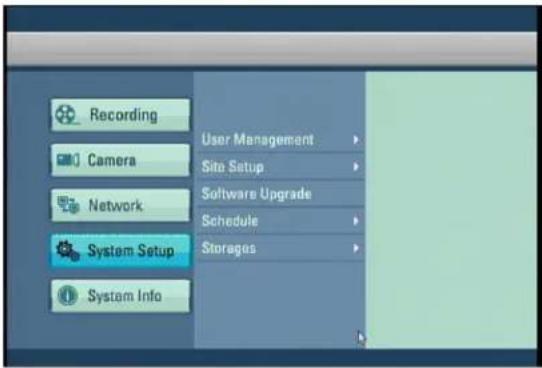
text_image
Recording Camera Network System Setup System Info User Management Site Setup Software Upgrade Schedule Storages4.5.1 User Management
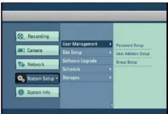
- The details of the User Management menu are as follows:
text_image
Recording Camera Network System Setup System Info User Management Site Setup Software Upgrade Schedule Storages Password Setup User Addition Setup Group Setup4.5.1.1 Password Setup
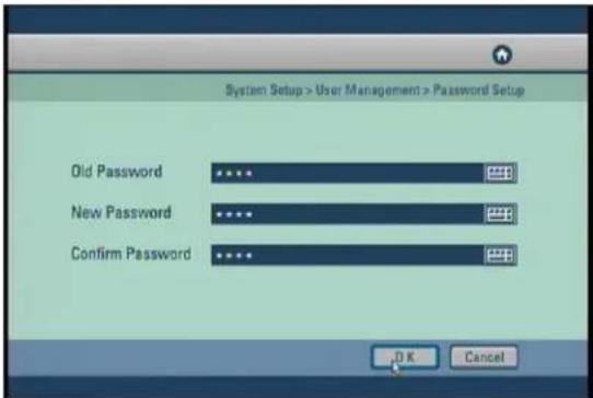
- Change the password for the administrator.
text_image
System Setup > User Management > Password Setup Old Password **** **** **** **** **** **** **** **** **** **** **** **** **** **** **** **** **** **** **** **** **** **** **** **** **** **** **** **** **** **** **** **** **** **** **** **** **** **** **** **** **** **** **** **** **** **** **** **** **** **** **** **** **** **** **** **** **** **** **** **** **** **** **** **** **** **** **** **** **** **** **** **** **** **** **** **** **** **** **** **** **** **** **** **** **** **** **** **** **** **** **** **** **** **** **** **** **** **** **** **** ** K Cancel[Old Password]
- The default password is not designated first time. This must be used when changing the password.
[New Password]
- A virtual keyboard will appear if the "Enter" button is pressed. You can input characters one by one up to 16 characters.
[Confirm Password]
- This is the menu for confirming the new password. You need to enter "New Password" first. If you enter the "Confirm Password" first without entering the "New Password", no response is made on the entry.
4.5.1.2 User Addition Setup
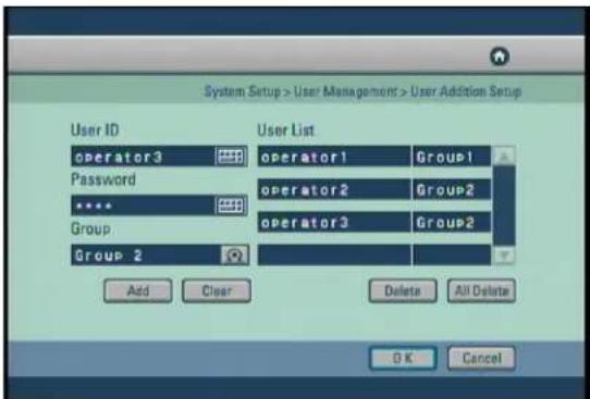
- Add new user and select the access level.
text_image
System Setup > User Management > User Addition Setup User ID operator3 Password Group Group 2 User List operator1 operator2 operator3 Add Clear Delete All Delete OK Cancel[User Add]
Enter "User ID" and "Password" for the User. Then select the group that the user has permission, there are three options "Group1", "Group2", and "Group3".
- If you press "Add", the entry is registered and displayed in the user list on the right.
- If you press "Clear", then User ID and Password details entered on the left are deleted.
[User Delete]
- First select a User ID to be deleted from the user list on the right, select it by pressing the "Enter" button.
- If you press "Delete", only the selected User ID is deleted from the list.
- If you press "Delete All", all the User IDs registered to the list are deleted.
4.5.1.3 Group Setup
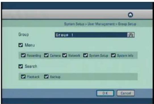
- Change the parameters set to each group.
text_image
System Setup > User Management > Group Setup Group Group 1 ✓ Menu ✓ Recording ✓ Camera ✓ Network ✓ System Setup ✓ System Info ✓ Search ✓ Playback ✓ Backup OK Cancel[Group]
- There are 3 user group levels, so each group can be set with different permission for system set up and search modes.
[Menu]
- Check "Recording" to enable set-up permission to Motion detection, Schedule, Quality/Resolution, Property.
- Check "Camera" to enable set-up permission to Channel setting, Alarm In Setting, Alarm In/Alarm Out link, Alarm In/Camera link, Spot Out/Camera link.
- Check "Network" to enable set-up permission to DDNS Setup, Network Setup, Network Test, NTP Setup, Emergency Notification.
- Check "System Setup" to enable set-up permission to User Management, Site Setup, Software Upgrade, Schedule, Storage.
- Check "System Info" to enable set-up permission to Log Info, Factory Default, System Shutdown/Restart.
[Search]
- Check "Playback" to enable search.
- Check "Backup" to set up the JPEG/BMP, KDB and SFX backup and remote backup for any image saved.
4.5.2 Site Setup
• The details of the Site Setup menu are as follows:
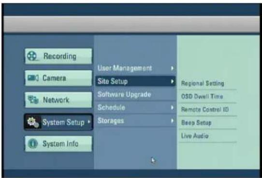
text_image
Recording Camera Network System Setup System Info User Management Site Setup Software Upgrade Schedule Storages Regional Setting OSD Dwell Time Remote Control ID Beep Setup Live Audio4.5.2.1 Regional Setting
- The regional settings menu is for change the DVR time and date to fit the time zone and language to the installation country. Also there is the option for changing the site code which is essential for network connection.
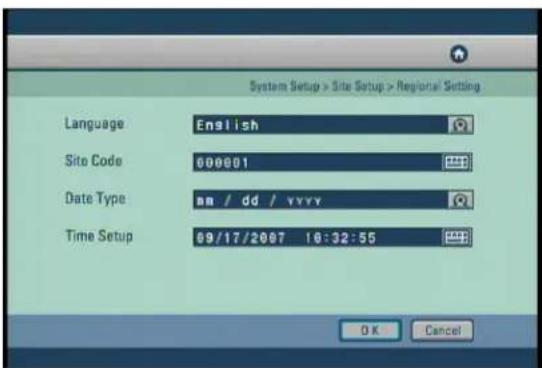
text_image
System Setup > Site Setup > Regional Setting Language English Site Code 000001 Date Type ma / dd / yyyy Time Setup 09/17/2007 10:32:55 OK Cancel[Language]
- Select the language you wish to use.
[Site Code]
- Setup the ID code to the system, for identifying the system when multiple systems are connected through network and to increase network security.
- The Site Code comprise 6 digits. When entering Site Code, you can enter a maximum of 6 digits.
![Digital Watchdog DW716N-1000 - [Site Code] - 1](/content/2026/05/819966/images/30073f8f1293aa44e6dbf54924778cca234ee538fba328b74a72a2732bcd07a6.jpg)
text_image
System Setup > Site Setup > Regional Setting Site Code 000001 1 2 3 4 5 6 7 8 9 0 ← OK Cancel[Date Type]
- It supports a total of 9 formats (such as Year-Month-Day/Day-Month-Year/Month-Day-Year).
[Time Setup]
- The following screen appears if the "Enter" button is pressed.
![Digital Watchdog DW716N-1000 - [Time Setup] - 1](/content/2026/05/819966/images/b958c0200f52753f251361d0791feb2c2363ed07d733c829bf52838ff2aef0e0.jpg)
text_image
System Setup > Site Setup > Regional Setting Current Time 09/17/2007 10:33:34 Time Zone (GMT) Casablanca, Monro Year Mon Day Hour Min Sec 2007 9 17 16 33 34 Daylight Saving OFF Caution : Cannot Change date and time setup when the NTP setup is enabled. OK Cancel[Current Time]
- It shows a currently set time.
[Time Zone]
- You can change Time Zone setting to suit installation Time Zone location.
[Daylight Saving]
- Daylight Saving sets the clock one hour ahead or behind during the daylight saving period. If the time zone supports daylight saving then there will be an option to turn off and on.
4.5.2.2 OSD Dwell Time
- Configure the setup of the on screen display (OSD) and the dwell time for the camera sequencing.

text_image
System Setup > Site Setup > OSD Dwell Time QSD All ON Event Monitoring Duration OFF Camera Name ON Recording ON Audio ON P / T / Z ON Backup ON Date / Time ON HDD Space ON Dwell Time 3 SEC Transparency 0% Bad Sector Dwell Time NOT USE OK Cancel- You can turn the display settings in Surveillance mode on or off, such as [OSD All], [Event Monitoring Duration], [Camera Name], [Recording], [Audio], [P/T/Z], [Backup], [Data/Time], [HDD Space], [Dwell Time], [Transparency] and [Bad Sector Dwell time] displays.
- Select [OSD All] to turn all screen displays using the mouse or jog and shuttle dial to switch on or all off.
[Event Monitoring Duration]
- Select to display when a event happened in watch mode for linked camera during event time period.
[HDD Space]
- Set whether to display HDD space on watch screen.
- You can set the channel sequence time from 1 second to 60 seconds by changing the value of [Dwell Time] by using the mouse wheel or the jog/shuttle dial.
- Select [Transparency] to enable transparency function.
[Bad Sector Dwell Time]
- You can set on the watch screen the display time that the bad sector icon shows when Bad sector happens.
![Digital Watchdog DW716N-1000 - [Bad Sector Dwell Time] - 1](/content/2026/05/819966/images/232cbba3104e346d90947a470c6639989af208f8a49769204ee623bbf2b3150b.jpg)
Bad Sector Icon
4.5.2.3 Remote Control ID
- In the situation where multiple DVR are using their own remote controller the Remote controller ID menu allows configure each controller to have it's own ID.
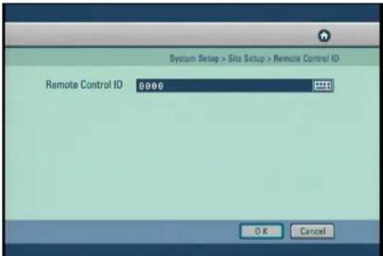
text_image
System Setup > Site Setup > Remote Control ID Remote Control ID 0000 OK Cancel[Remote ID]
- In order to control the DVR with a remote controller, set the DVR and the remote control ID the same.
- Click the button to set a unique Remote control ID.
[Note]
- The Remote ID must be of four digit for example, When the Remote ID is '0' input '0000'.
- By default, the Remote ID of the DVR is set to '0'. With the Remote ID set to '0', you can control the DVR without adjusting the remote controller.
- To change the remote controller ID, press [SysID] button, and input the ID of the corresponding system. Then, press [SysID] button again.
- Setting the Remote IDs of several DVRs to '0' lets you control all of them at once.
4.5.2.4 Beep Setup
- Select the delay time (sec) between video signal loss and beep alarm activation.
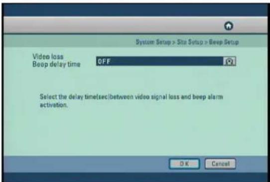
text_image
System Setup > Site Setup > Beep Setup Video loss OFF Beep delay time Select the delay time(sec) between video signal loss and beep alarm activation. OK Cancel[Video loss Beep delay time]
- The delay time for the video loss alarm can be set. If you do not wish to use the video loss Beep then set the menu to 'off' using the mouse or jog and shuttle dial.
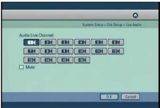
4.5.2.5 Live Audio
text_image
System Setup > Site Setup > Live Audio Audio Live Channel OK EN EN ON EN ON ON ON ON ON ON ON ON ON ON ON Mute OK Cancel[Audio Live Channel]
- Select channel for live audio output.
• The units supports only one channel live audio output at a time.
[Mute]
- Check [Mute] button to disable audio output on audio channel.
4.5.3 Software Upgrade
- View the current software and upgrade to new version.
[Package select]
- You can upgrade the system program by using a portable storage device to be recognized by DW-6/7 series. The upgrade package must be in a folder called "update". Connect the storage device containing an upgrade package to the USB port, then press [Select]. The system will display the number of packages found.
[Upgraded Version]
- After a portable storage device is connected, you can select the [Upgrade Version] using the mouse wheel or the jog/shuttle on the system.
[Current Version]
- You can view the current system program version.
Check to make sure the upgrade package version is higher than the current version, then select [Start] to begin the upgrade.
[Caution]
- When upgrading is in progress, do not switch off the system or unplug the portable storage device containing the upgrade package until the upgrade is complete. Otherwise the system may malfunction.
4.5.4 Schedule
• The details of the Schedule menu are as follows:
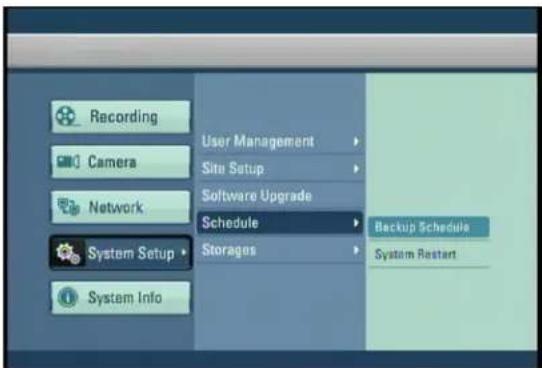
text_image
Recording Camera Network System Setup System Info User Management Site Setup Software Upgrade Schedule Storages Backup Schedule System Restart4.5.4.1 Backup Schedule
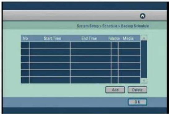
- You can set up a system backup schedule so that the system will automatically save backup copies of specific recording times.
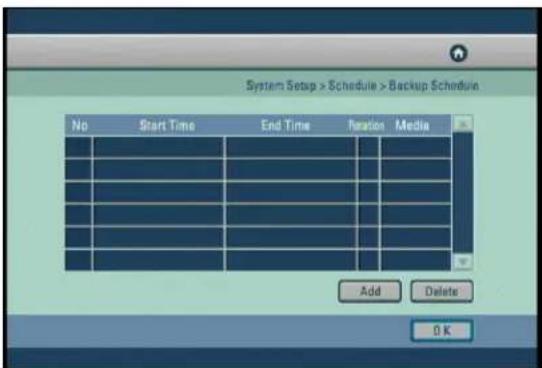
text_image
System Setup > Schedule > Backup Schedule No Start Time End Time Rotation Media Add Delete OK- Backup Schedule programs the system to save a backup copy of the recorded data to a designated storage device set in the schedule.
- You can only schedule the system to save a backup copy of the recording that will be recorded in the future. You cannot schedule the system to save a backup that has been recorded before the current date. To do this, you must access the search mode.
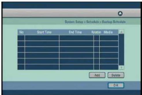
4.5.4.1.1 Adding Backup schedule
text_image
System Setup > Schedule > Backup Schedule No Start Time End Time Rotation Media Add Delete OK[Add]
- To add a backup schedule to the list, select [Add] button.
![Digital Watchdog DW716N-1000 - [Add] - 1](/content/2026/05/819966/images/abda0b3e0b263d07ea8e77f7533196d482a9a03ad3f94203e996a8fd6ec2c337.jpg)
text_image
System Setup > Schedule > Backup Schedule Start Time 09/06/2007 14:04:28 End Time 09/06/2007 14:09:28 Target Drive USB Rotate WEEKLY OK Cancel- To add a backup schedule, you must set the [Start Time] and [End Time], [Target Drive], and [Rotate] options.
![Digital Watchdog DW716N-1000 - [Add] - 2](/content/2026/05/819966/images/d671fb07a569e7a3d6b89a23c47127fd196ef12605b692edf813ab130ea24530.jpg)
text_image
System Setup > Schedule > Backup Schedule No Start Time End Time Rotation Media 91 99/06/07 14:04 99/06/07 14:09 N USB 92 99/06/07 14:05 99/06/07 14:10 N USB Add Delete OK[Backup Schedule List]
- You will see the added schedule on the backup Schedule list. Select [OK] button to accept the schedule and return to Setup menu.
4.5.4.1.2 Deleting Backup Schedule
text_image
System Setup > Schedule > Backup Schedule No Start Time End Time Rotation Media Add Delete 0 K[Delete]
- To delete a schedule from the list, select the schedule you wish to delete by using the directional keys and Enter key. Then select [Delete] button to delete the schedule.
4.5.4.2 System Restart
text_image
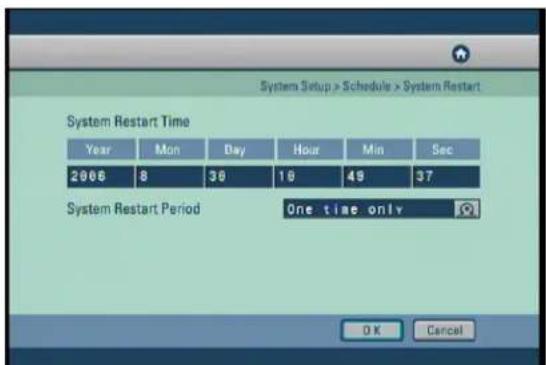
System Setup > Schedule > System Restart System Restart Time Year Mon Day Hour Min Sec 2006 8 39 18 49 37 System Restart Period One time only OK Cancel[System Restart Time]
- You can set a time when the system will automatically restart.
[System Restart Period]
- Use the mouse wheel or the jog/shuttle to select [System Restart Period]. You can assign the system to automatically restart [On time only], [Daily], [Every 2 days], [Every 3 days], [Weekly], [Every 2 weeks], [Every 3 weeks], or [Monthly].
- Restarting the system on regular basis may help stabilize the system performance.
4.5.5 Storage
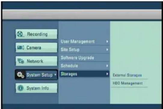
• The details of the Storage menu are as follows:
text_image
Recording Camera Network System Setup System Info User Management Site Setup Software Upgrade Schedule Storages External Storages HDD Management4.5.5.1 Backup Schedule
- Setup external storage for backup device or extended recording storage device.
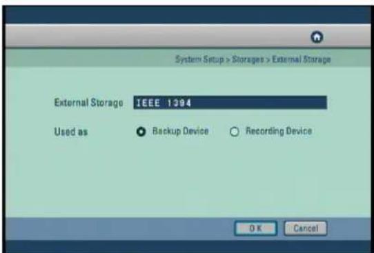
text_image
System Setup > Storages > External Storage External Storage: IEEE 1394 Used as Backup Device Recording Device OK Cancel[External Storage]
- Display external storage device type.
[Used as]
- External Storage can serve as a backup device or the recording device.
- Select 'Backup Device' to use the external storage as backup device, and 'Recording Device' as the recording device, and click the [OK] button.
[Note]
- Do not disconnect the cable or turn off external storage during operation.
(May cause the DVR system to malfunction or damage the file system of the external storage. In case of damage to the file system of the external storage, or recover program)
4.5.5.2 Hard Disk Format
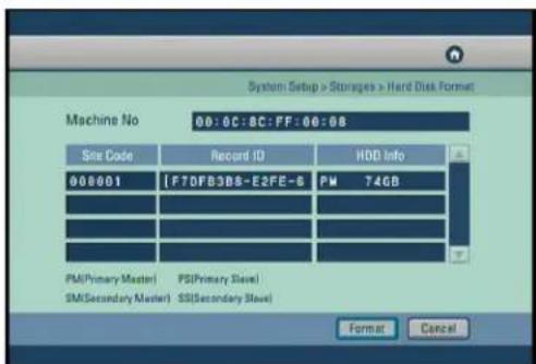
text_image
System Setup >Storages > Hard Disk Format Machine No 00:0C:0C:FF:00:0B Site Code Record ID HDD Info 000001 IFTDFB3DS-E2FE-6 PM 74GB PM(Primary Master) PS(Primary Slave) SM(Secondary Master) SS(Secondary Slave) Format Cancel- The table shows the system's built-in HDD's and their information. You can install up to HDD into the system.
- Form the table, you can select the HDD you wish to format, then select [OK] button.
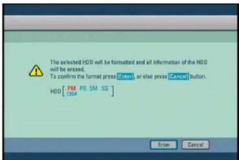
text_image
The selected HDD will be formatted and all information of the HDD will be erased. To confirm the format press [Enter], or else press [Cancel] button. HDD [PM PS SM SS] Enter Cancel- The system will display a warning message. To confirm and proceed with formatting the selected HDD, press [Enter] button. To cancel format and return to HDD table, select [Cancel] button.
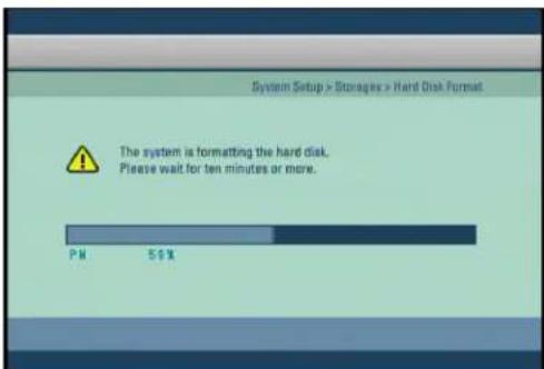
text_image
System Setup > Storages > Hard Disk Format The system is formatting the hard disk. Please wait for ten minutes or more.- You can view the HDD format progress through the progress bar.
- The system will restart once the format is complete.
[Caution]
- Because all data will be deleted when the HDD formatting is executed, please proceed with the initialization after backing up important data to other place.
[Caution]
Checking HDD Data
Please, pay attention to following information to minimize the change of losing HDD data.
- Remember that you should protect HDD from any impact or misuse as this may cause damaged.
- The Manufacturer is not responsible for missing data or defects caused by the user's miss handling.
Note : Adding Extra HDD. Check in advance that the HDD is compatible with the manufacturer's DVR.
Example that can cause loss of data or damage HDD.
- Any outside impact on the case which could happen whilst disassembling or setting up the DVR.
- Power cut or incorrect shutdown whilst the DVR is operating.
- Moving or causing any impact on the DVR during operation.
Please, back up events as soon as possible to minimize disappointment should HDD data be lost.
4.6 System Info
• The details of the System Info menu are as follows :
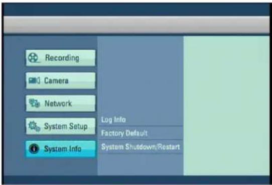
text_image
Recording Camera Network System Setup Log Info Factory Default System Info System Shutdown/Restart4.6.1 Log Info
- This function shows as series of logged tasks made in operating the DVR system and when the system runs abnormally, it allows finding the error easily so that the problem can be fixed.
- Press the Enter button after moving the cursor on the desired log item.

Move to the previous page.
Move to the next page.
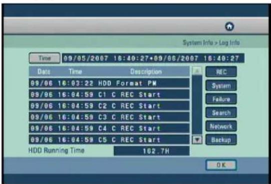
text_image
System Info > Log Info Time 09/05/2007 18:40:27+09/06/2007 16:40:27 Date Time Description 09/06 16:03:22 HDD Format PM 09/06 16:04:59 C1 C REC Start 09/06 16:04:59 C2 C REC Start 09/06 16:04:59 C3 C REC Start 09/06 16:04:59 C4 C REC Start 09/06 16:04:59 C5 C REC Start HDD Running Time 162.7H REC System Failure Search Network Backup OK[Time]
- If the [Time] button is pressed, the following screen appears.
![Digital Watchdog DW716N-1000 - [Time] - 1](/content/2026/05/819966/images/6b591b802cd62beac4316a0cd3d5000c6e22e864e36f8b90b338dd2f9a239b15.jpg)
text_image
Start Time 89 / 65 / 2007 16 : 44 : 21 Year Mon Day Hour Min See 2007 9 5 16 44 21 End Time 89 / 66 / 2607 16 : 44 : 21 Year Mon Day Hour Min See 2007 9 6 16 44 21 OK Cancel- Select [Time] to change time to view log information recorded on different date/time.
- Change [Start Time] and [End Time] using the mouse and mouse wheel or the directional keys and the jog/shuttle, then press [OK] button. The system will display the log information recorded during this period.
[REC]
- Displays the recording information according to the recording event and schedule.
[System]
- Displays the system start/stop, system access user and setup change information.
[Failure]
- Displays the error information that occurs due to the hardware failure.
[Search]
- Displays the time information between the entry and exit of the search mode.
[Network]
- Displays the time and IP address for the connected system through the remote software.
[Backup]
• Displays the backup information.
* System Log List
| Log Type | Log Details | Description |
| • REC | C(Channel) C REC START/STOP | Continuous Recording Start/Stop |
| C(Channel) A REC START/STOP | Alarm In Recording Start/End | |
| C(Channel) M REC START/STOP | Motion Recording Start/End | |
| • System | SYSTEM START/STOP | System Power ON/OFF |
| System Time ChangeSYSTEM NET TIMESET | ||
| System TerminationSYSTEM SHUTDOWN | ||
| System Restart SYSTEM REBOOT | ||
| Menu mode Login/LogoutSETUP START/END | ||
| Weak Video Output Signal/WEAK SIGNAL START CH | ||
| WEAK SIGNAL STOP CH | Video Output Signal Restoration | |
| HDD Format M | HDD(Master) Format | |
| HDD Format S | HDD(Slave) Format | |
| Video Loss/RecoveryVIDEO LOSS START/STOP• Failure | ||
| Fan Failure/RecoveryFAN FAILURE/RECOVERY | ||
| HDD(Master) Smart Check FailureSMART ERROR HDD-M | ||
| SMART ERROR HDD-S | HDD(Slave) Smart Search Failure | |
| HDD(Master) Write Error CountHDD ERR COUNT M | ||
| HDD(Slave) Write Error CountHDD ERR COUNT S | ||
| Login/Logout with the Search ModeSEARCH IN/OUT• Search | ||
| Remote Software ConnectionNETWORK CONNECTED• Network | ||
| NETWORK DISCONNECTED | Disconnecting the Remote Software Connection | |
| • BACKUP | BACKUP AVI-OK/FAILED | AVI Backup Success/Failure |
| SDB Backup Success/FailureBACKUP SDB-OK/FAILED | ||
| BACKUP SFX-OK/FAILED | SFX Backup Success/Failure | |
| BAKCUP BMP-OK/FAILED | BMP Backup Success/Failure | |
| BACKUP JPEG-OK/FAILED | JPEG Backup Success/Failure | |
| USB PROBLEM DETECTED | Removing the Media While Backing up to a USB Storage | |
| CD-ROM WRITE FAIL | CD Write Failure | |
| CD Media Size Full | No CD Space Remained | |
| CD Media Not Exist | No CD Media |
4.6.2 Factory Default
- Restore the all settings to the original default settings. It is also possible to input and export setting from other DW-6/7 series.
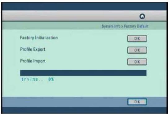
text_image
Systems Info > Factory Default Factory Initialization OK Profile Export OK Profile Import OK trvina... 0% OK[Factory Initialization]
- Returns all the settings back to the original default condition. Click on the OK button using the mouse or directional buttons on the front to select the factory initialization.
[Profile Export]
- Creates a file with the System Profile that can be saved and used on other DW-6/7 series.
- Insert USB storage device into DW-6/7 series use mouse or Directional keys to select [OK] and start Export. When complete OK message appears, If no storage is inserted message 'No USB' will appear or if drive is full or error happens fail message will appear.
[Profile Import]
- Import a system profile from another DW-6/7 series.
- Insert USB storage device with profile on into DW-6/7 se use mouse or Directional keys to select [OK] and start Import. When complete OK message appears, if no storage is inserted massage 'no USB' will appear or if drive is full or error happens fail message will appear.
4.6.3 System Shutdown/Restart
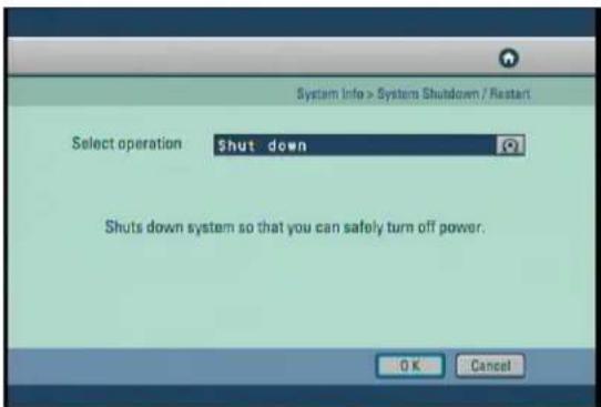
text_image
System Info > System Shutdown / Restart Select operation Shut down Shuts down system so that you can safely turn off power. OK Cancel[Shut down]
- Shut down the system.
[Restart]
- Restart the system.
5. Search
5. Search
5.1 Accessing Search Mode
To go to the Search screen, click the [SEARCH] button shown in the front of the system screen. The login window will then be displayed, enabling the inputting of login ID and password as shown below.
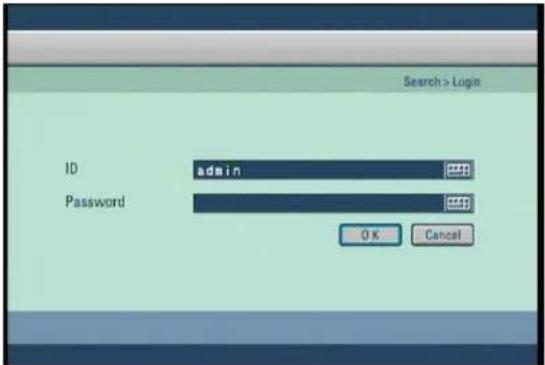
text_image
Search > Login ID admin Password OK Cancel- Click the password.) button to enter the desired login ID and password. (The admin account initially has no
- Enter the desired login ID and password and click the [OK] button. The search screen is then displayed as shown below.
- If you forget your password, you will not be able to access Search mode, or change your password. We strongly recommend that you either write down your password and keep it safe or use a password that you are sure to remember. (See page 69 for instructions on how to change password.)
• To return to Surveillance mode, press [Search] button at anytime.
5.2 Search mode display
After you enter the correct password, the Search mode display will appear as shown below.
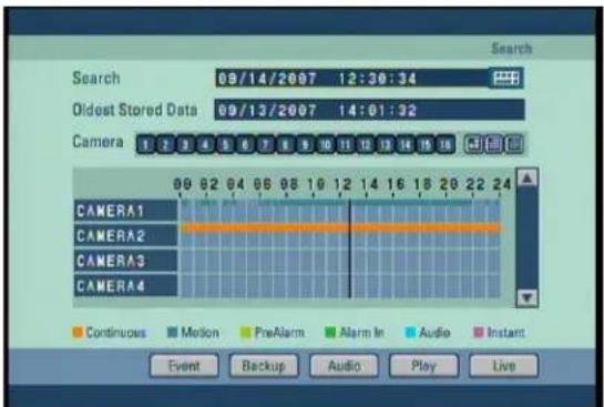
text_image
Search 09/14/2007 12:30:34 Oldest Stored Data 09/13/2007 14:01:32 Camera 1 2 3 4 5 6 7 8 9 10 11 12 13 14 15 16 CAMERA1 CAMERA2 CAMERA3 CAMERA4 Continuous Motion PreAlarm Alarm In Audio Instant Event Backup Audio Play Live5.3 Selecting date and time
• To select the date you wish to view, use the directional keys to select Enter. This will display a calendar.
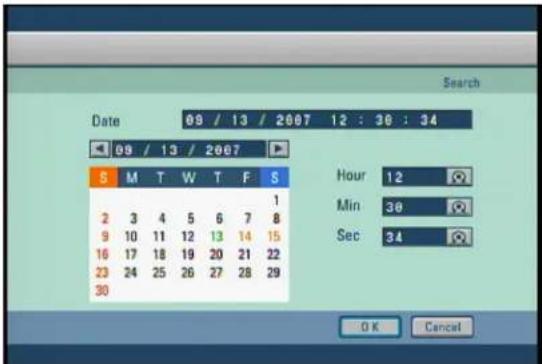
text_image
Date 09 / 13 / 2007 12 : 30 : 34 09 / 13 / 2007 S M T W T F S 1 2 3 4 5 6 7 8 9 10 11 12 13 14 15 16 17 18 19 20 21 22 23 24 25 26 27 28 29 30 Hour 12 Min 38 Sec 34 OK Cancel- Press the arrow buttons (◀▶) above the calendar to change year/month.
- Use the directional keys to select the date and press Enter.
- Dates containing recorded data are displayed in an orange color (see table 5-2 for color descriptions).
- Use the shuttle Dial on the system or the mouse wheel to change hour / minute / second.
• After selecting the date you wish to view, press the [OK] button to return to Search mode display. The system will display the selected date's recording in the time graph.
| Date Color | Description |
| • Orange | Date with Recorded Data |
| • Red | Holidays/Weekends |
| • Black | Date without Data |
| • Green | Selected Date |
| • Blue | Current Date |
[Note] Jog and Shuttle Dial
- Jog Dial: Changes hour/minute/second or any other setup value precisely.
- Shuttle Dial: Changes hour/minute/second or any other setup value quickly
5.4 Selecting cameras and changing search bar line
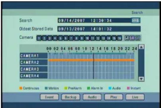
text_image
Search 09/14/2007 12:30:34 Oldest Stored Data 09/13/2007 14:01:32 Camera CAMERA1 CAMERA2 CAMERA3 CAMERA4 Continuous Motion PreAlarm Alarm In Audio Instant Event Backup Audio Play Live[Selecting cameras]
- You can select the cameras to be selected. After pressing the Camera1 to Camera16 buttons on the front panel or moving the cursor to the channel to be selected, the cameras can be selected by pressing the [Enter] button.
[Changing Search bar line]
- To shift the search bar line, use the jog or shuttle dial on the system or the mouse wheel. This will shift the bar left or right. Shifting the search bar line will change the time of the recording you wish to view.
[Time graph]
- Recorded data shown on the time graph will be displayed in different colors depending on the recording type enabled.
| Color | Description |
| • Orange | Continuous Recording |
| • Blue | Motion-detection Recording |
| • Light Green | Pre-alarm Recording |
| • Green | Alarm In Recording |
| • Bluish Green | Audio Recording |
| • Purple | Instant Recording |
5.5 Audio Output
- To select the date you wish to view, use the directional keys to select Enter. This will display a calendar.
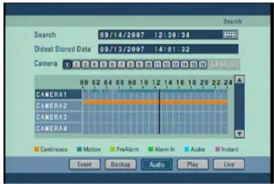
text_image
Search 89/14/2007 12:30:34 Oldest Stored Data 89/13/2007 14:01:32 Camera 1 CAMERA1 CAMERA2 CAMERA3 CAMERA4 Continuous Motion PreAlarm Alarm In Audio Instant Event Backup Audio Play Live[Audio]
- The system can play the video with recorded audio, provided an audio recording device is connected to that channel.
- To play the recording with sound, use the mouse or the directional keys on the system to select the [AUDIO] button, then press [PLAY]. Once selected, you will listen to any recorded audio.
[Note]
- Only one camera channel can output audio data for replay.
- Audio data are outputted only during forward play, not during backward or fast replay.
5.6 Playback
- If you press [Play] after selecting the channel and date to be searched, the video is played.
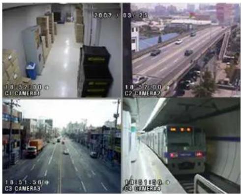
text_image
2007 / 03/25 18:52:00 C1 CAMERA1 18:52:00 C2 CAMERA2 18:51:50 C3 CAMERA3 18:51:56 C4 CAMERA4[Playback buttons ]
: Move to the first recorded image for that date.
: Reverse Play.
: Stop.
: Forward Play.
: Move to the last recorded image for that date.
[Fast Play]
- If you press the left or right button ( / ) while in playing, you can see the screen in the reverse or forward direction with the 2-times speed, 3-times speed or 4-times speed.
[Full Screen]
- To enlarge a channel during playback, use the number keys 1\~16 on the system to select the channel you wish to enlarge.
- When a channel is selected, use ▲▼ (zoom in/zoom out) keys to increase or decrease the screen size.
[Conversion into the initial Search Screen or Monitoring Screen]
- To return to Search mode display, press the Enter button at anytime.
- To shift from the search screen to the surveillance screen press the [SEARCH/LIVE] button.
[Note]
- Recording frame rate might vary depending on the number of installed camera or system load.
5.7 Event Search
- Event search function can be used to search and display data recorded by motion, or alarm events.
- The following Event Search screen will appear if the [Event] button is pressed.
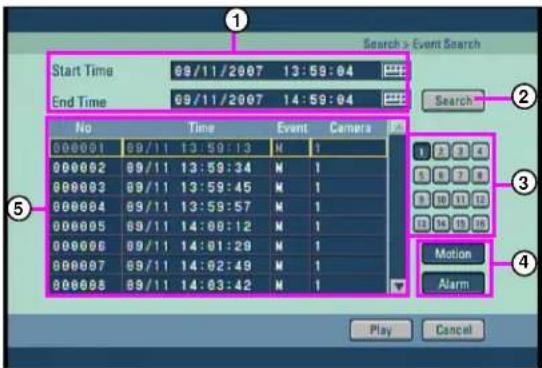
text_image
Search > Event Search Start Time 69/11/2007 13:59:04 End Time 69/11/2007 14:59:04 No Time Event Camera 000001 09/11 13:59:13 N 1 000002 09/11 13:59:34 N 1 000003 09/11 13:59:45 N 1 000004 09/11 13:59:57 N 1 000005 09/11 14:08:12 N 1 000006 09/11 14:01:28 N 1 000007 09/11 14:02:49 N 1 000008 09/11 14:03:42 N 1 Search Motion Alarm Play Cancel① [Start Time] and [End Time]
- Set the Event search time.
- To change the [Start Time] and [End Time], use the mouse or the directional buttons to highlight button, then click left mouse button or press Enter.
![Digital Watchdog DW716N-1000 - ① [Start Time] and [End Time] - 1](/content/2026/05/819966/images/52805033cf76ce691be1b5b78782fdf801d7b33b87b2a1a8f053e59d70b2e17c.jpg)
②[Search]
- Click on the "Search" button to start the event search.
③[Camera]
- Select the camera or channel to search.
④[Choose event items to search]
- Select the item which you want to search, choose either or both Motion and Alarm Events.
[Event List]
⑤. This part is displays searched result. Choose the event from the list you want to playback and click the [Play] button then event images will be played back.
6. Backup
6. Backup
- From Search screen display, select [BACKP] button to save a backup copy of the recording using USB HDD, or a portable hard drive such as USB memory stick. The backup files can be saved as SFX, BMP, JPEG, or KDB (Data Base) formats.
6.1 Video Backup
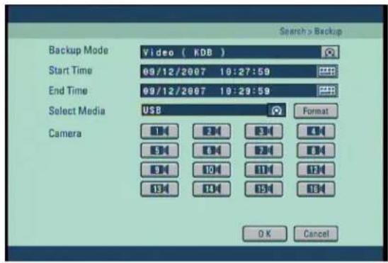
text_image
Backup Mode Video ( KDB ) Start Time 09/12/2007 10:27:59 End Time 09/12/2007 10:29:59 Select Media US$ Camera OK Cancel Search > Backup[Backup mode – Video]
- First select KDB, SFX Backup mode, use the mouse or the directional keys on the system to highlight [Backup mode], then use the mouse wheel or the jog/shuttle to change the option.
[Start Time] and [End Time]
- Select the start time and end time of the recording you wish to save.
- To change the [Start Time] and [End Time], use the mouse or the directional buttons to highlight button, then click left mouse button or press Enter.
![Digital Watchdog DW716N-1000 - [Start Time] and [End Time] - 1](/content/2026/05/819966/images/5f759442b14491287c2198dc5199d841f7a2b2c50c2af57ea4b1ec4c089d8a14.jpg)
[Select Media]
- Select the media to be used for saving backup.
- When selecting USB or IEEE1394, the [Format] button will be initialized. Push [Format] button when you need to format the chosen media.
[Camera]
- Select the camera number that contains the recording you wish to save.
- When saving backup in KDB format, you can select multiple camera channels.
- When saving backup in SFX format, you can only select one camera channels.
- When saving backup in Video mode, you will see channels in Surveillance mode.
[Note]
- KDB (Data Base) backup enables backup of the video with audio data. However, the other types of backup such as BMP, JPG do not include audio.
- When the is archived to USB in KDB format the viewer software will be copied automatically to the USB.
- SFX file is backup file format include player in a file.(EXE)
- If double click backup SFX file, backup date will play automatically.
6.2 Still Image Backup
- To back up still images, replay the recorded image first and press the Enter once you reach the scene that you would like to back up. The initial search screen in then converted into the initial search screen.
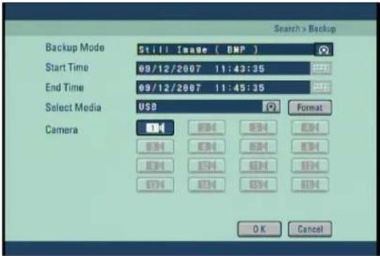
text_image
Backup Mode Still Image ( BMP ) Start Time 09/12/2007 11:43:35 End Time 09/12/2007 11:45:35 Select Media USB Format Camera OK Cancel[Backup mode – Still Image]
- First select KDB, SFX Backup mode, use the mouse or the directional keys on the system to highlight [Backup mode], then use the mouse wheel or the jog/shuttle to change the option.
[Start Time] and [End Time]
- Select the start time and end time of the recording you wish to save.
- To change the [Start Time] and [End Time], use the mouse or the directional buttons to highlight button, then click left mouse button or press Enter.
![Digital Watchdog DW716N-1000 - [Start Time] and [End Time] - 1](/content/2026/05/819966/images/14ba54ef069f4739252649a9811dc1b35e6498a2d035f0f91f0f3414cc051c61.jpg)
[Select Media]
- Select the media to be used for saving backup.
- When selecting USB or IEEE1394, the [Format] button will be initialized. Push [Format] button when you need to format the chosen media.
[Camera]
- When Still Image mode is selected, only those cameras what selected in search mode will be saved. Camera channels that do not contain any data will be disabled.
- Press [OK] button to begin backup. You will see the backup progress through the progress bar.
- One backup is complete, the system will return to search mode display.
6.3 Media Format
- On Backup Mode to format external storage equipment (USB, IEEE1394) or set partition, select the media (USB or IEEE1394) then click the [Format] button
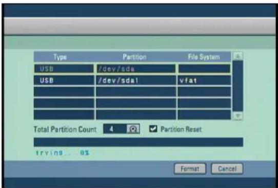
text_image
Type Partition File System USB /dev/sda USB /dev/sdal vfat Total Partition Count 4 ✓ Partition Reset trying... 0% Format Cancel[Format]
- Click [Format] button after selecting the storage equipment which you want to format on media list.
[Establishing partition]
- Select the storage equipment which you want to establish partition(s).
- Check the [Partition Reset] button and set the partition quantity on [Total Partition Count]. And then push [Format] button.
[Note]
- Media format function is not supported when external storage equipment (USB, IEEE1394) is set on recording mode.
- Storage equipment format function is supported for only USB or IEEE1394.
- Please allow 5 seconds for the unit to recognize external storage after connecting.
- When entering the Media Format screen right after connecting, the related info may not be displayed on list.
- [Total Partition Count] setting only works when the [Partition Reset] button has been checked.
6. Appendix
1. KDB Viewer
1.1 How to run Viewer
① Connect or insert saved KDB type backup data media to computer, Double click [KDBViewer] Folder to open.
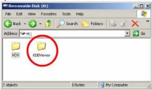
text_image
Removable Disk (Ht) File Edit View Favorites Tools Help Back Search Folders Address H: KDO IDEViewer Go 2 objects D bytes My Computer② Double click 'Viewer.exe' to run viewer application.
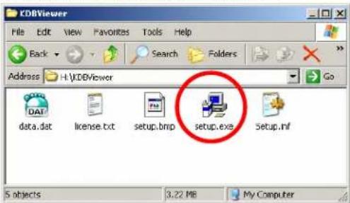
text_image
KDBViewer File Edit View Favorites Tools Help Back Search Folders Address H:\KDBViewer Go data.dat license.txt setup.bmp setup.exe Setup.nl 5 objects 3.22 MB My Computer③ Click on next button.
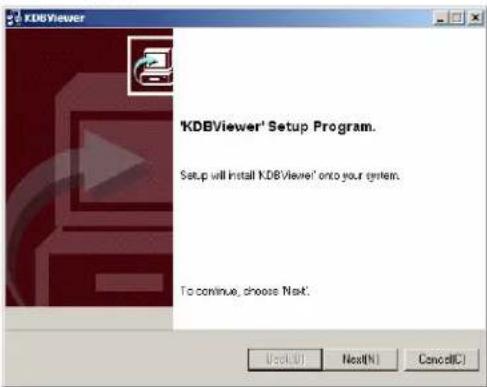
text_image
'KDBViewer' Setup Program. Setup will install KDBViewer' onto your system. To continue, choose Next.

Check the box "I accepted this License Agreement" and click on [Next]3
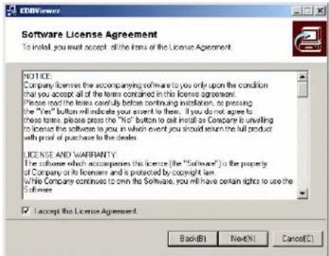
text_image
ECONViewer Software License Agreement To install, you must accept all the terms of the License Agreement. NOTICE: Company licenses the accompanying software to you only upon the condition that you accept all of the terms contained in this license agreement. Please read the terms carefully before continuing installation, so passing the "Yes" button will indicate your consent to them. If you do not agree to these terms, please press the "No" button to exit install as Company is unvaling to license the software to you, in which event you should return the full product with proof of purchase to the dealer. LICENSE AND WARRANTY: The software which accompanies this license (the "Software") is the property of Company or its licensed and is protected by copyright law. While Company continues to own the Software, you will have certain rights to use the Software. I accept this License Agreement. Back(B) Next(N) Cancel(C)
Enter the path to install the CMS program, and click on [NEXT] button.
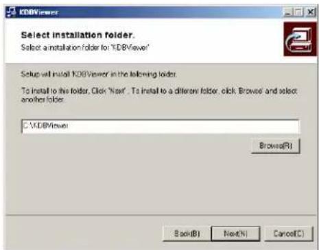
text_image
KDBViewer Select installation folder. Select a installation folder for "XDBViewer" Setup will install XDBViewer in the following folder. To install to the folder, Click "Next". To install to a different folder, click, Browse and select another folder. C:\XDBViewer Browse(R) Back(B) Next(N) Cancel(C)
Installation will start.
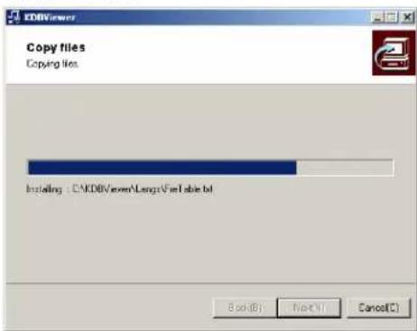
text_image
COPY files Copying files Installing : C:\KDBV.exe\Long\Fire\lab.btl Back(B) Next(N) Cancel(C)⑥ After the Center Program is completely installed, click on [FINISH] button.
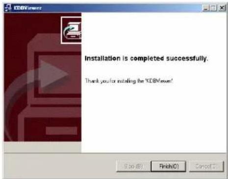
text_image
Installation is completed successfully. Thank you for installing the XDBViewer!⑦ On the desktop, "KDBViewer.exe"
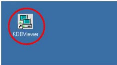
text_image
KDBViewer1.2 Viewer main screen
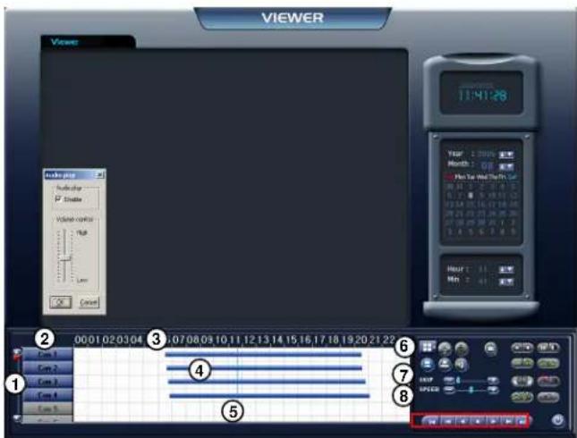
text_image
VIEWER Viewer 12:41:28 Video frame Number/stop 700 Video control 16 Lamp Cancel Year 1 2005 Month 1 09 Min Tan Wed The Sun 08:41:0 27:36:16 0.7 8 9 8:51:02 08:54:0 16:12:18:08 09:21:03 26:25:08 09:28:08 21:1 2 14:45:0 27:36:16 Hour 1 11 Min 2 41 00:01:02:03:04 3:07:08:09 10:11:12:13:14 15:16:17:18 19:20:21:23 Core 1 Core 2 Core 3 Core 4 Core 5 ① ② ③ ④ ⑤ ⑥ ⑦ ⑧① [Scroll button for camera]
- Scroll up or down to show camera buttons.
② [Camera]
- Select camera number(s) you wish to search.
③ [Time indication bar]
- It indicates time of stored data.
- To enlarge the time scale, click on the time indication bar.
④ [Indication of stored data]
- This function indicates recording type and stored data in graphical colour form as below;
- Pink bar indicates 'Continuous recording'.
- Blue bar indicates 'Motion recording',
- Dark Yellow bar indicates 'Sensor recording',
- Green bar indicates 'Pre-alarm recording',
- No graphic bar where nothing was recorded.
⑤ [Search Line]
- This indicates time line for searching data.
- Move the line to the left or right to start searching.
⑥ [Split Screen setup]
- When you click the button, split mode from search screen will automatically change according to the number of cameras you choose in a form of 4, 9, or 16 (DW-6/7 series) split screen.
⑦ [SKIP]
- Move the slides to the right if you wish to increase search speed.
- The number of images to be skipped are set by an internal value of the DW Center software. The value is not the number of images to be skipped.
⑧ [SPEED]
- Move the slides to the right to increase the speed of replaying saved image.
![Digital Watchdog DW716N-1000 - ⑧ [SPEED] - 1](/content/2026/05/819966/images/5a69e105b614271bf3a82cfabd3913bc41de30aa6e4fe530c8805bf84763adf8.jpg)
text_image
VIEWER Viewer Audio Player P Change Volume control High OK Cancel 11:41:28 Time 1:00:00 Month 1:00:00 Run Time And Run To 34 10:31:17 10:31:17 12:19:17 12:19:17 15:00:17 15:00:17 16:00:17 16:00:17 17:00:17 17:00:17 18:00:17 18:00:17 19:00:17 19:00:17 20:00:17 20:00:17 21:00:17 21:00:17 22:00:17 22:00:17 23:00:17 23:00:17 24:00:17 24:00:17 25:00:17 25:00:17 26:00:17 26:00:17 27:00:17 27:00:17 28:00:17 28:00:17 29:00:17 29:00:17 30:00:17 30:00:17 31:00:17 31:00:17 32:00:17 32:00:17 33:00:17 33:00:17 34:00:17 34:00:17 35:00:17 35:00:17 36:00:17 36:00:17 37:00:17 37:00:17 38:00:17 38:00:17 39:00:17 39:00:17 40:00:17 40:00:17 41:00:17 41:00:17 42:00:17 42:00:17 43:00:17 43:00:17 44:00:17 44:00:17 45:00:17 45:00:17 46:00:17 46:00:17 47:00:17 47:00:17 48:00:17 48:00:17 49:00:17 49:00:17 50:00:17 50:00:17 51:00:17 51:00:17 52:00:17 52:00:17 53:00:17 53:00:17 54:00:17 54:00:17 55:00:17 55:00:17 56:00:17 56:00:17 57:00:17 57:00:17 58:00:17 58:00:17 59:00:17 59:00:17 60:00:17 60:00:17 61.23.23.23.23.23.23.23.23.23.23.23.23.23.23.23.23.23.23.23.23.23.23.23.23.23.23.23.23.23.23.23.23.23.23. 9 9 9 9 9 9 9 9 9 9 9 9 9 9 9 9 9 9 9 9 9 9 9 9 9 9 9 9 9 9 9 9 9 9 9 9 9 9 9 9 9 9 9 9 9 9 9 9 9 9 9 Core 1 Core 2 Core 3 Core 4 Core Timeline Core 1 Core 2 Core 3 Core 4 Core Core 1 Core 2 Core 3 Core 4 Core Core 1 Core 2 Core 3 Core 4 Core Core 1 Core 2 Core 3 Core 4 Core Core 1 Core 2 Core 3 Core 4 Core Core 1 Core 2 Core 3 Core 4 Core Core 1 Core 2 Core 3 Core 4 Core Core 1 Core 2 Core 3 Core 4 Core Cone End Cone End Cone End Cone End Cone End Cone End Cone End Cone End Cone End Cone End Cone End Cone End Cone End Cone End Cone End Cone End Cone End Cone End Cone End Cone End Cone End Cone End Cone End Cone End Cone End Cone End Cone End Cone End Cone End Cone End Cone End Cone End Cone End Cone End C one end c one end c one end c one end c one end c one end c one end c one end c one end c one end c one end c one end c one end c one end c one end c one end c one end c one end c one end c one end c one end c one end c one end c one end c one end c one end c one end c one end c one end c one end c one end c one end c one end c one end c two end c two end c two end c two end c two end c two end c two end c two end c two end c two end c two end c two end c two end c two end c two end c two end c two end c two end c two end c two end c two end c two end c two end c two end c two end c two end c two end c two end c two end c two end c two end c two end c two end c two e n t o r i n t o r i n t o r i n t o r i n t o r i n t o r i n t o r i n t o r i n t o r i n t o r i n t o r i n t o r i n t o r i n t o r i n t o r i n t o r i n t o r i n t o r i n t o r i n t o r i n t o r e n t o r e n t o r e n t o r e n t o r e n t o r e n t o r e n t o r e n t o r e n t o r e n t o r e n t o r e n t o r e n t o r e n t o r e n t o r e n t o r e n t o r e n t o r e n t o r e n t o r a l l l l l l l l l l l l l l l l l l l l l l l l l l l l l l l l l l l l l l l l l l l l l l l l l l l l l l l l l l l l l l l l l l l l l l l l l l l l l l l l l l l l l l l l l l l l l l l l l l l l | Core I Core I Core I Core I Core I Core I Core I Core I Core I Core I Core I Core I Core I Core I Core I Core I Core I Core I Core I Core I Core I Core I Core I Core I Core I Core I Core I Core I Core I Core I Core I Core I Core I Core I Core I Core I Core I Core I Core I Core I Core I Core I Core I Core I Core I Core I Core I Core I Core I Core I Core I Cone End Cone End Cone End Cone End Cone End Cone End Cone End Cone End Cone End Cone End Cone End Cone End Cone End Cone End Cone End Cone End Cone End Cone End Cone End Cone End Cone End Cone End Cone End Cone End Cone End Cone End Cone End Cone End Cone End Cone End Cone End Cone End Cone End Cone End Cone End Cone End Cone End Cone End Cone End Cone End Cone End Cone End Cone End Cone End Cone End Cone End Cone End Cone End Cone End Cone End Cone Start![Digital Watchdog DW716N-1000 - ⑧ [SPEED] - 2](/content/2026/05/819966/images/a09bd38730b55e48e9e4566fdbb9d8acf4a2e37135ec30054de7f1428df199e8.jpg)
[Zoom]
![Digital Watchdog DW716N-1000 - [Zoom] - 1](/content/2026/05/819966/images/dcf9bcfca532d7313c9df2f236535077b936bf4a23c135eb5bf9363be103a796.jpg)
Increases screen size by up to x4.
![Digital Watchdog DW716N-1000 - [Zoom] - 2](/content/2026/05/819966/images/452d9fcf2685eebad8410cd591b759d55b516ab84f99f1971e8eea35621f7a5d.jpg)
[Digital Zoom]
![Digital Watchdog DW716N-1000 - [Digital Zoom] - 1](/content/2026/05/819966/images/11360857dfc952cb772b0272aaa16c46968e79861a9ccd14a33e9701c862d704.jpg)
[Zoom In]
Click right mouse button to increase the selected part of the image by up to x17 (when recorded by high resolution).
![Digital Watchdog DW716N-1000 - [Digital Zoom] - 2](/content/2026/05/819966/images/32eb677101e5cdd27b844d36afd20cd9db38749a788a760583e848c46652cf26.jpg)
[Zoom Out]
Click right mouse button to reduce zoom ratio.
![Digital Watchdog DW716N-1000 - [Digital Zoom] - 3](/content/2026/05/819966/images/f08b915e00ec369f3505185aed0ace0a830759c72f9fe880b70cd8eb9198f79e.jpg)
[Move]
Click right mouse button and drag to "move around inside" the stored image.
![Digital Watchdog DW716N-1000 - [Digital Zoom] - 4](/content/2026/05/819966/images/68ce48058bded64c17a56877b0886258f2ff334bfbca3eb9c407583b2e44adff.jpg)
[Playback]
- Be sure to select the camera, time and date to search.
- Adjust SKIP and SPEED ratio as you wish.
![Digital Watchdog DW716N-1000 - [Playback] - 1](/content/2026/05/819966/images/037ec3e9e63de4a9f2515c1b51c6f904287eb05623e8dd5ca577462501991d45.jpg)
Go to first saved image for selected date
![Digital Watchdog DW716N-1000 - [Playback] - 2](/content/2026/05/819966/images/3c1cae0e1301351a67fb38bc4498f348c1897b36e59210165cb992e51b8bab27.jpg)
Reverse play frame by frame
![Digital Watchdog DW716N-1000 - [Playback] - 3](/content/2026/05/819966/images/a35f95711cd95d310f4b021dde1761048a3242f3125680c1c89d37d6e82fea27.jpg)
Reverse playback
![Digital Watchdog DW716N-1000 - [Playback] - 4](/content/2026/05/819966/images/c29d57baaf74fb47bd097511197d0df7b940a37b7ebed1bf42884e75b6e3047b.jpg)
Stop
![Digital Watchdog DW716N-1000 - [Playback] - 5](/content/2026/05/819966/images/46a11a6d4ce2acbf50cf2101b9ee90bfa9bc54ab03649cd0321db72dd522e23b.jpg)
kup]
![Digital Watchdog DW716N-1000 - kup] - 1](/content/2026/05/819966/images/8e472e8f2ffa11655c363a5a77c096d0bab9cf05db37baea3abfd8292450c17d.jpg)
While you are searching recorded data,
select the image to backup and click
The "Backup" window will appear.
![Digital Watchdog DW716N-1000 - kup] - 2](/content/2026/05/819966/images/dfafdbc868debf6071931f0ae335f2969d14480c6a7fe37e4609eebba565ddf8.jpg)
![Digital Watchdog DW716N-1000 - kup] - 3](/content/2026/05/819966/images/cf1ce62ab494565680f08c5fc7e52a6226dac80395b0daf140ccb595ebf0e653.jpg)
[Print]
![Digital Watchdog DW716N-1000 - [Print] - 1](/content/2026/05/819966/images/6ed96235219d0417c8453d6d4b77f7dfb511d7fd5b2ca9bccd78fe5f013e27a1.jpg)
Print the selected image.
It is possible to print BMP or JPEG images.
⑭ [Audio Play Configuration]
- When you want to playback audio, select the channel with recorded audio. (Audio recording and replay is supported for only one channel).
- When you click the 'Audio Play' icon, the audio play configuration window appears as right.
- Check on "Enable".
- Adjust the volume properly using 'Volume control'.
⑮ [Adjustment of playback image]
- Image quality, such as brightness, contrast, colour, sharpness, rotate, mirror, outline and twist function during playback can be adjusted.
![Digital Watchdog DW716N-1000 - ⑮ [Adjustment of playback image] - 1](/content/2026/05/819966/images/005d1c1722177178f342e978e7d2dcbfec28799bb796e6d50ee1f945b267ca8b.jpg)
text_image
Audio play Audio play Enable Volume control High Low OK Cancel⑯ [Search Sheet]
- When you click the icon [=] for searching the backup data, a window as below will appear. - Select DW Series which contains backup data, then select the site you wish to search and click 'Search' to start.
![Digital Watchdog DW716N-1000 - ⑯ [Search Sheet] - 1](/content/2026/05/819966/images/0656c94e637bdc1c0827feb3e75549ea4117bd72d1d77e8c5d711209e91ae2f2.jpg)
text_image
Site Code Date Type Date and Time Time Zone Path 00001 Backup 07/15/2006 06:19 (GMT) Case HWGBBackup Search Exit[Quit]
- Exit the Viewer program.
2. WebDVR
Connect WebDVR
- Input DVR IP address to connect on Web Browser (Internet Explorer) as blow picture.
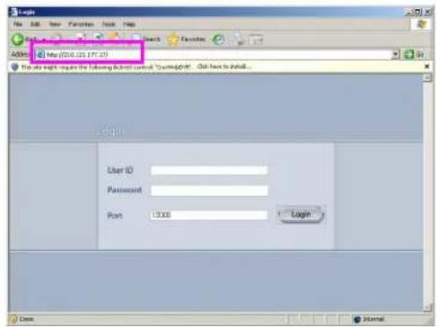
text_image
Login File Edit View Favorites Book Help Search Favorites Address http://200.01.17.23 The site rights request the following Active Control "Overweight": Click here to install... Login User ID Password Port 13.00 Login Name Internal[Note]
- To operate WebDVR without errors on Windows Vista, execute "Internet Explorer" as an administrator. And then you can get the right the access to download ActiveX program.
-
To execute "Internet Explorer" as an administrator.
-
Click "Start" button.
- If you have program lists, wave cursor "Internet Explorer" menu and click right button on the mouse.
- If you have pop-up menu, click "Run as Administrator" menu.
![Digital Watchdog DW716N-1000 - [Note] - 1](/content/2026/05/819966/images/122cc6a5a1f15d0ae04aa16dad6011b536ed0c414e9a32aa186017d806830daa.jpg)
text_image
Open Save Asynchronous Find to Build More Find to Build New Create new data series Send To Go Gray Update Rename Properties Rename Properties Browse Back- Select "Install ActiveX Control" on popup menu.
![Digital Watchdog DW716N-1000 - [Note] - 2](/content/2026/05/819966/images/b802235508ddc782b9f852e83fd3d027d1eaa250b489b7496ea84a99ce71dfb5.jpg)
text_image
Login File Edit View Favorites Tools Help Back Search Favorites Address http://210.121.177.17/ This site might require the following ActiveX controls "Class/WebC" Install ActiveX Control... What is the Help? Information Bar Help- After pop-up message, click "Install" to install software.
![Digital Watchdog DW716N-1000 - [Note] - 3](/content/2026/05/819966/images/c4a6d660fd9e8ab15d9cffe9d4c4065fbf356761a3fe948a6489820758580f63.jpg)
text_image
Windows Explorer - Security Warning Do you want to install this software? Name: CnawebDAR 8 More options Install Don't Install While file from the internet can be useful, the file type can potentially harm your computer. Only install software from publishers you trust. What's the task?- After install is complete, the screen below will be displayed. Insert ID and password to connect to DVR, and then click "Login".
![Digital Watchdog DW716N-1000 - [Note] - 4](/content/2026/05/819966/images/a82572ebcbdc4b97c30e6d4295476c9e7430fe3c10197babba10fa4ad13de355.jpg)
text_image
Login File Edit View Favorites Tools Help Back Search Favorites Address http://210.123.177.12/ Login User ID: admin Password ••••• Port 12000 Login Done InternetLive Watch Mode
![Digital Watchdog DW716N-1000 - [Note] - 5](/content/2026/05/819966/images/ae87b15230dfc373b9303337e4a083981665d1d697d92938e696f51f86ea8857.jpg)
text_image
Live Watch File Edit View Favorites Tools Help Back Search Favorites Address: http://210.221.377.17\newwatch_ao.html WEL-DBK V7A53 V7A53 V7A53 V7A53 V7A53 V7A53 V7A53 V7A53 V7A53 V7A53 V7A53 V7A53 V7A53 V7A53 V7A53 V7A53 V7A53 V7B29 V7B29 V7B29 V7B29 V7B29 V7B29 V7B29 V7B29 V7B29 V7B29 V7B29 V7B29 V7B29 V7B29 V7B29 V7B29 V7B29 V7A53 V7A53 V7A53 V7A53 V7A53 V7A53 V7A53 V7A53 V7A53 V7A53 V7A53 V7A53 V7A53 V7A53 V7A53 V7A53 V7D29 V7D29 V7D29 V7D29 V7D29 V7D29 V7D29 V7D29 V7D29 V7D29 V7D29 V7D29 V7D29 V7D29 V7D29 V7D29 V7D29 V7A53 V7A53 V7A53 V7A53 V7A53 V7A53 V7A53 V7A53 V7A53 V7A53 V7A53 V7A53 V7A53 V7A53 V7A53 V7A53 L00 14 14 14 14 14 14 14 14 14 14 14 14 14 14 14 14 14 14 14 14 14 14 14 14 14 14 14 14 14 14 14 14 14 14① View Panel: It can be shown live picture from DVR. And each channel screen can be moved through Drag and Drop.
② Live Watch : Press button to enter the live display.
③ Playback : Press button to enter the search display.
④ Split button : Choose the screen division displayed by 4/6/9/10/13/16/25/33/36 splits.
⑤ Search date : Input the search date and time.
⑥ Timeline panel : Displays the information about the recording data for selected day. The time graph can be zoomed by clicking on the timeline and click anywhere on the graph to move the playback time to that location.
⑦ Refresh : If you click on the button, the timeline will update with the latest recorded data.
⑧ Playback panel: Controls to adjust the playback of recorded data, select play/reverse, one image at a time and move to first and last image of the day.
⑨ Live mode conversion : It is a function to convert from 1 channel playback back to watch.
⑩ Speed/Volume: Change the playback speed and volume.
![Digital Watchdog DW716N-1000 - [Note] - 6](/content/2026/05/819966/images/3cc600b37a659b8643d29a71a3c11f80dffd3f904d357a373f85494d3b3f0bd5.jpg)
text_image
Search Mode File Edit View Favorites Tools Help Back Search Favorites Address http://218.121.177.17\playback.html WEB DVD KODI COMPUTER KODI COMPUTER 2000/2001/2002/2003/2004/2005/2006/2007/2008/2009/2010/2011/2012/2013/2014/2015/2016/2017/2018/2019/2020/2021/2022/2023/2024/2025/2026/2027/2028/2029/2030/2031/2032/2033/2034/2035/2036/2037/2038/2039/2040/2041/2042/2043/2044/2045/2046/2047/2048/2049/2050/2051/2052/2053/2054/2055/2056/2057/2058/2059/2060/2061/2062/2063/2064/2065/2066/2067/2068/2069/2070/2071/2072/2073/2074/2075/2076/2077/2078/2079/2080/2081/2082/2083/2084/2085/2086/2087/2088/2089/2090/2091/2092/2093/2094/2095/2096/2097/2098/2099/2100/2101/2102/2103/2104/2105/2106/2107/2108/2109/2110/2111/2112/2113/2114/2115/2116/2117/2118/2119/2120/2121/2122/2123/2124/2125/2126/2127/2128/2129/2130/ KODICOM Live Watch Playback ① ② ③ ④ ⑤ ⑥ ⑦ ⑧ ⑨ Dow: Interval① View panel: Displays the playback of recorded data.
② Live Watch : Press button to enter the live display.
③ Playback : Press button to enter the search display.
④ Split button : Choose the screen division displayed by 4/6/9/10/13/16/25/33/36 splits.
⑤ Search date : Input the search date and time.
⑥ Timeline panel : Displays the information about the recording data for selected day. The time graph can be zoomed by clicking on the timeline and click anywhere on the graph to move the playback time to that location.
⑦ Refresh : If you click on the button, the timeline will update with the latest recorded data.
⑧ Playback panel: Controls to adjust the playback of recorded data, select play/reverse, one image at a time and move to first and last image of the day.
⑨ Speed/Volume: Change the playback speed and volume.
3. Watermark Checker
① Double click 'WMChecker.exe' to run Watermark program
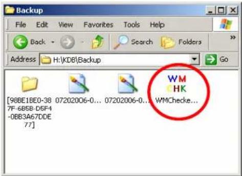
text_image
Backup File Edit View Favorites Tools Help Back Search Folders Address H:\KD8\Backup Go [968E18E0-38 07202006-0... 07202006-0... WMChecke... 7F-685B-DSF4 -0BB3A67DDE 77]② Press 'File Open' button to select backup still image data (BMP, JPEG)
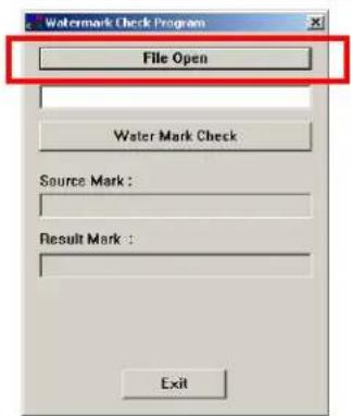
text_image
Watermark Check Program File Open Water Mark Check Source Mark : Result Mark : Exit③ Select image to check forgery.

text_image
Open Look in: Backup File name: 0230306-015547[01].bmp File type: Bitmap File("bmp, Jpeg File("jpeg", Jpeg, A/) Open Cancel④ If select correctly, it will be shown as below picture.
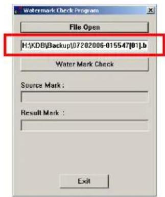
text_image
Watermark Check Program File Open H:\KDB\Backup\07202006-015547[01].b Water Mark Check Source Mark : Result Mark : Exit⑤ Press [Water mark Check] button to check forgery of selected file as below pictures
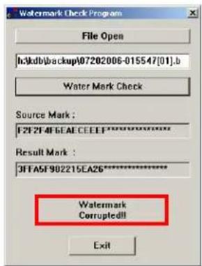
text_image
Watermark Check Program File Open h:\kdb\backup\07202006-015547[01].b Water Mark Check Source Mark : F2F2F4F6EACEEEF****** Result Mark : 3FFA5F902215EA26****** Watermark Corrupted!! Exita. Modified Image
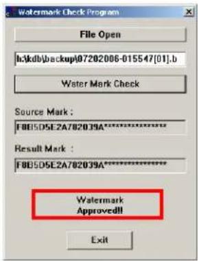
text_image
Watermark Check Program File Open h:\kdb\backup07202006-015547[01].b Water Mark Check Source Mark : F8E5D5E2A782039A***** Result Mark : F8E5D5E2A782039A***** Watermark Approved!! ExitB. Original Image
4. Adding HDD
4.1 Installing new HDD
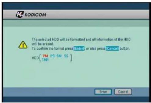
text_image
KODICOM The selected HDD will be formatted and all information of the HDD will be erased. To confirm the format press [Enter], or else press [Cancel] button. HDD[PM PS SM SS] Enter Cancel- Turn the system off and install the new HDD into the system.
- Turn the system back on and wait for the HDD format message.
- The message will ask you to confirm HDD format. HDD format is a necessary procedure before using the newly installed HDD.
- Press [Yes] button to being formatted the new HDD. Pressing [No] button will cancel HDD format and shutdown the system.

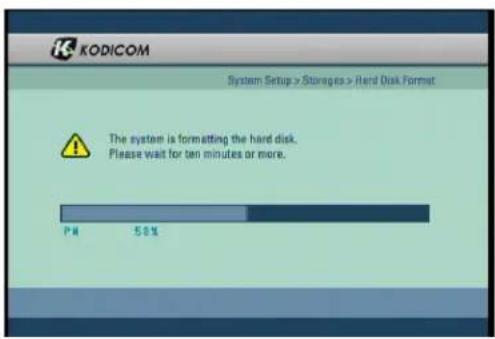
text_image
KODICOM System Setup > Storages > Hard Disk Format The system is formatting the hard disk. Please wait for ten minutes or more.- Once the system begins formatting the HDD, you can view the progress through the progress bar.
- Once HDD is complete, the system will restart.
[Note]
- Before attaching a new HDD to the system, you are recommended to check both the original HDD and the new HDD interface jumper and set the MASTER and SLAVE.
- Any newly installed HDD must be formatted
- Remember that formatting will erase any data stored on the new HDD. Please make sure you have saved any important data before proceeding with HDD format.
4.2 Checking HDD Database
![Digital Watchdog DW716N-1000 - [Note] - 1](/content/2026/05/819966/images/58c890e73fb981b7fe98b8e516bbaaf84e6a461a97064c28a9fd821b6497abbb.jpg)
text_image
KODICOM System Setup >Storages > Hard Disk Format Machine No 00:0C:8C:FF:00:0B Site Code Record ID HDD Info 900001 I F7DFB3B8-E2FE-6 PW 74GB P&I Primary Master P&I Primary Stave S&I Secondary Master S&I Secondary Stave Format Cancel- If the newly installed HDD database does not correspond with the original HDD, the system will display the HDD table.
- If the database of the HDD does not correspond, you must format either the system's original HDD or the newly installed HDD.
- From the table, you can select the HDD you wish to format, then select [OK] button. The system will display a confirmation message. Select [Cancel] button to exit HDD table screen.
![Digital Watchdog DW716N-1000 - [Note] - 2](/content/2026/05/819966/images/86059b5cfb5e99f2b4f940b498bbee988871cd6d1dad05dab60bbc6efe29295a.jpg)
text_image
KODICOM The selected HDD will be formatted and all information of the HDD will be erased. To confirm the format press [Enter], or else press [Cancel] button. HDD [PM PS SM SS-] Enter Cancel![Digital Watchdog DW716N-1000 - [Note] - 3](/content/2026/05/819966/images/804170dc05bd3cf9809f773be328ef9b979c21e43063e205ebcfaa6a85d4814f.jpg)
text_image
KODICOM System Setup > Storages > Hard Disk Format The system is formatting the hard disk. Please wait for ten minutes or more.- You can view the HDD format progress through the progress bar.
- The system will restart once the format is complete.
[Caution]
• Any newly installed HDD must be formatted
- Remember that formatting will erase all data stored on the selected HDD. Please make sure you have saved all important data before proceeding with HDD format
5. Specifications
System Specifications
- HDD : Max. HDD x 2
• O/S : Embedded Linux
• LAN : Ethernet 10/100 Mb/s - Modem : 56Kbps. External-type modem is supported. (Optional, but not available in Europe)
Video Input
| Model | Video Input (NTSC/PAL) |
| DW-604T | 4CH Composite Video |
| DW-608T/708T | 8CH Composite Video |
| DW-616T/716T | 16CH Composite Video |
Video Output
• General Monitor Spot output (BNC)
• S-Video Output Port
• VGA Output Port
• Video Loop Through Port for Each Video Input
Recording Frame
| Model | Recording Frame |
| DW-604T/608T/606T | NTSC (Max 120 fps), PAL (Max 100 fps) |
| DW-708T/716T | NTSC (Max 240 fps), PAL (Max 200 fps) |
Audio Recording
| Model | DW-604T | DW-608T | DW-616T | DW-708T | DW-716T |
| Audio Channels | 4CH | 8CH | 8CH | 8CH | 16CH |
• 1 Live Audio Support
Compression Method
• Mpeg-4 ASP
Display Mode
| Model | Display Mode | Display Frame |
| DW-604T | 1, 4 Split | NTSC(120fps), PAL (100fps) |
| DW-608T/708T | 1, 4, 9 Split | NTSC (240fps), PAL (200fps) |
| DW-616T/716T | 1, 4, 9, 16 Split | NTSC (480fps), PAL (400fps) |
Auto Sequence
• Automatic channel rotation in order of x1,x4,x9 Screen Division (DW-616T/716T)
Playback Display Mode
- Playing in split screen mode up to 1, 4, 9, 16-splitscreen is possible (DW-616T/716T)
- Enlarging an image to full screen is possible
Alarm In & Alarm Out
| Model | ALARM IN Channels | ALARM OUT Channels |
| DW-604T | 4CH | 4CH |
| DW-608T/708T | 8CH | 8CH |
| DW-616T/716T | 16CH | 16CH |
Remote Controller
Motion Detection
Camera/ Alarm In link - Yes
Pan/ Tilt/ Zoom Control - Yes
Backup
- Auto/Manual backup through USB portable storage device, CD-RW/DVD-RW or remote drive via network.
Mouse (USB)
Power
- The rated voltage might vary depending on the specification of the supply.
| Input VoltageModel | |
| AC 115-230V, 60-50Hz, 4-2AENP-2320 |
Weight: 10.14Kg (HDDx4)
Dimensions
• Body (mm): 430 (W) × 508 (L) × 88 (H)
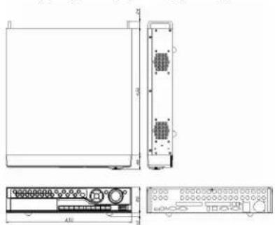
text_image
Technical diagram of an electronic device with labeled components and dimensions6. FAQ

The system power does not turn on.
Check if the power cable is connected correctly.
Check if the input voltage is correct.
If the system power does not turn on when the power cable is connected correctly, please contact the service Center.

The system power is turned on, but no video data is displayed on the monitor.
- Check if the monitor power cable is connected properly
Check to make sure the monitor is turned on.
Check if the video output cable of DW-6/7 series DVR is properly connected to the monitor. - Unplug the power cable and plug in again.
When VGA monitor is selected as an image output, it takes about 1 minute after power connection to view the image on the VGA monitor. Be sure to wait until the processing window appears.

The camera numbers are displayed on the screen, but camera images are not displayed.
Check if the camera video output is connected to DW-6/7 series DVR system correctly.
Check if the power cable on the camera is connected correctly.
Check if the video cable connecting the camera to DW-6/7 series DVR system has a problem.
This problem can occur because of weak video signal if the video data is transferred by a video data distributor when the video is connected to multiple systems. Connect the camera directly to DW-6/7 series DVR.
Turn off DW-6/7 series system and turn it on again.

The camera video is shown on the screen, but the system doesn't record video.
Check to make sure the recording mode in the recording setting mode is not set to "NONE".
Turn off the DW-6/7 series DVR and turn it on again.

It is impossible to search through the recorded video.
Check if there is recorded video data for the time that you are trying to search.
If there is no recorded video data, check to make sure the record mode in the recording setting mode is not set to "NONE".

Audio data recorded with video data is not playing.
Check if the audio recording option is correctly set to the camera you wish to record audio.
Check if the audio play option in the Search mode is selected.
Check if the microphone and speaker port on the rear of DW-6/7 series system are connected correctly.
Check if the connected microphone is working properly.
Check if the connected speaker is working properly.

Color of some camera videos are strange or videos are shown abnormally.
Check if the camera connected to the system has a problem. Check to make sure the camera is not damaged by trying another camera into a working video output.
Check if the video system setting is the same with your camera system. Depending on your region, the camera system can support either PAL, or NTSC. Depending on the camera system, the video process can differ greatly, therefore it can be difficult to recognize the video data if the video system setting is different from the camera system.

There are a lot of (screen) noise on the image.
Check if the video signal output from the camera has a problem. Check to make sure the camera is not damaged by trying the camera on another video input or direct to monitor.
Check if the video cable connecting the camera and DW-6/7 series DVR is cut, cross-wired, or shorted.
Check if there is a high voltage wire around the video cable connecting the camera to DW-6/7 series DVR system. It can cause the noise problem to decrease video quality.
Check if the video cable connecting the camera to DW-6/7 series DVR system is the correct video cable. When a normal power-supplying cable is used instead of the video cable, screen noise can be generated.

Sometimes the system restarts itself.
The system can restart itself due to watchdog function when any problem occurs to DW-6/7 series.
Remove HDD and check if the system stabilizes, if so replace or format original HDD.

The connected sensor is not operating.
Check if the type of sensor in camera setting is the same with the connected sensor.
Check if the system is set to use the sensor in recording schedule window in the recording setting menu.
Check if the power cable of the sensor is properly connected.
Check if the signal cable of the sensor is properly connected.

The connected control device is not operating.
Check if the system is set to use the control device in the camera setting menu.
Check if the power cable of the controller is properly connected.
Check if the signal cable of the controller is properly connected.
Warranty Guide
The quality of this product is guaranteed by strict quality control processes and testing.
If the product becomes non operational the warranty may be in operation. The warranty period is valid for 1 year from the date of purchase.
Warranty Guide
☐ Check the Product Warranty Sheet to make sure it is still in effect.
☐ Check the problem again and contact the dealer you purchased the unit from.
☐ About product repair, exchange, or refund, we follow the “compensation regulation for customer’s loss” announced by “the Economic Planning Board”. (Korea only)
Warranty
☐ If the product becomes non operational the warranty may be in operation. The warranty period is valid for 1 year from the date of purchase.
□ Service fee and replacement parts will be charged in the following cases:
-
Damaged due to the user's carelessness.
-
Damaged due to a natural disaster.
-
Damaged due to the user not following the instructions and cautions written in the user's guide.
-
Damaged due to incorrect power voltage, and/or frequency being used.
-
If the Product Warranty has expired.
-
Damaged due to anyone not employed by provider modifying the system.
☐ If your system is damaged after the expiration of the warranty period, free repair service will not be available. If you wish the system to be repaired, a service fee and replacement parts will be charged on a time & materials basis.
Product Warranty
| Product/ Model Name | ||
| Serial Number | ||
| Purchasing Dealer | ||
| Purchasing Date | ||
| Warranty Period | 1 year from the purchasing date. | |
| Customer | Name | |
| Address | ||
The Product Warranty Sheet will not be issued again.
The Product Warranty Sheet must be filled on the same day as the product's purchase.
This document must be shown in order to receive the free repair service.