AirMesh MST200 - Access Point Aruba - Free user manual and instructions
Find the device manual for free AirMesh MST200 Aruba in PDF.


User questions about AirMesh MST200 Aruba
0 question about this device. Answer the ones you know or ask your own.
Ask a new question about this device
Download the instructions for your Access Point in PDF format for free! Find your manual AirMesh MST200 - Aruba and take your electronic device back in hand. On this page are published all the documents necessary for the use of your device. AirMesh MST200 by Aruba.
USER MANUAL AirMesh MST200 Aruba
Aruba Mesh Router Web-based Configuration Guide
v4.2
ARUBA®
networks
ARUBA®
networks
Copyright
© 2011 Aruba Networks, Inc. All rights reserved.
Aruba Networks ^® is a registered trademark, and Aruba The Mobile Edge Company is a trademark of Aruba Networks, Inc.
Specifications are subject to change without notice.
Trademarks
Sygate On-Demand Agent and Sygate Enforcer are trademarks of Sygate Technologies.
All other trademarks or registered trademarks are the property of their respective holders.
Legal Notice
The use of Aruba Networks, Inc. switching platforms and software, by all individuals or corporations, to terminate Cisco or Nortel VPN client devices constitutes complete acceptance of liability by that individual or corporation for this action and indemnifies, in full, Aruba Networks, Inc. from any and all legal actions that might be taken against it with respect to infringement of copyright on behalf of Cisco Systems or Nortel Networks.
Warranty
This hardware product is protected by the standard Aruba warranty of one year parts/labor.
For more information, refer to the ARUBACARE SERVICE AND SUPPORT TERMS AND CONDITIONS.
Altering this device (such as repainting it) voids the warranty.
Table of Contents
CHAPTER 1 ABOUT THIS GUIDE ...... 6
1.1. SCOPE 6
1.2. AUDIENCE 6
1.3. RELATED DOCUMENTS 6
CHAPTER 2 WEB CONFIGURATION OVERVIEW....7
2.1. GETTING STARTED 7
2.1.1. Logging into the Web-based Management Interface 7
2.1.2. WMI Basics....8
CHAPTER 3 BASIC SETTINGS....9
3.1. BASIC SETTINGS....9
CHAPTER 4 CONFIGURING ETHERNET INTERFACE....11
4.1. CONFIGURING ETHERNET INTERFACE BASIC.... 11
4.2. CONFIGURING ETHERNET INTERFACE VLAN 12
4.3. CONFIGURING ETHERNET INTERFACE IPv4....13
4.4. CONFIGURING ETHERNET INTERFACE QOS....14
4.5. ETHERNET INTERFACE ADVANCED CONFIGURATION.... 15
CHAPTER 5 WIRELESS SETTINGS....16
5.1. RADIO INTERFACES CONFIGURATION.... 16
5.1.1. Configuring Radio Interface Basic.... 16
5.1.2. Configuring Radio Interface Backhaul.... 18
5.1.3. Configuring Radio Interface Advanced Settings 19
5.2. BSS INTERFACES CONFIGURATION 21
5.2.1. Creating a New BSS/Entering an Existing BSS.... 21
5.2.2. Configuring a New Created BSS/an Existing BSS 24
5.2.3. Configuring BSS Security 25
5.2.4. Configuring BSS VLAN 29
5.2.5. Configuring BSS IPv4 29
5.2.6. Configuring BSS QoS 30
5.2.7. Configuring BSS Advanced Settings 31
5.2.8. Deleting a BSS.... 33
5.3. MESH CONFIGURATION 33
5.3.1. Configuring Mesh Basic 33
5.3.2. Configuring Mesh Security 34
5.3.3. Configuring Mesh ACL List.... 37
5.3.4. Configuring Preferred Links.... 38
5.3.5. Configuring Mesh Advanced Settings.... 40
5.4. CLIENT MODE CONNECTION CONFIGURATION.... 41
5.4.1. Creating a New/Entering an Existing Client-mode Connection 42
5.4.2. Configuring a Client-mode Connection (STA) 44
5.4.3. Configuring Client-mode Connection Security 45
5.4.4. Configuring Client-mode Connection VLAN 48
5.4.5. Configuring Client-mode Connection IPv4.... 49
5.4.6. Configuring Client-mode Connection Scanning 50
5.4.7. Configuring Client-mode Connection Advanced Settings.... 51
CHAPTER 6 NETWORK SETTINGS....53
ARUBA®
networks
6.1. CONFIGURING ROUTING....53
6.1.1. Routing Table Configuration....53
6.1.2. Adding an IPv4 Static Route 54
6.1.3. Deleting an IPv4 Static Route.... 55
6.1.4. View IPv4 System Routing Table 56
6.1.5. OSPF Configuration Page 58
6.1.6. Adding OSPF Network 59
6.1.7. Deleting OSPF Network....59
6.1.8. Adding Summary Address.... 60
6.1.9. Deleting Summary Address.... 61
6.1.10. AWR Configuration Page.... 62
6.1.11. Multicast Configuration Page 64
6.2. CONFIGURING DHCP 64
6.2.1. DHCP Server Configuration 65
6.2.2. Adding a New DHCP Pool.... 66
6.2.3. Configuring the New DHCP Pool.... 66
6.2.4. Deleting an Existing DHCP Pool 68
6.2.5. Adding an IP Address Range.... 68
6.2.6. Deleting an IP Address Range.... 69
6.2.7. Adding an Fixed IP Assignment.... 70
6.2.8. Deleting an Existing Fixed Assignment 70
6.2.9. Deleting DHCP Option 71
6.2.10. DHCP Relay Configuration.... 72
6.2.11. Deleting DHCP Relay 72
6.3. CONFIGURING VLAN 73
6.3.1. VLAN Configuration....73
6.3.2. Adding VLAN Interface 74
6.3.3. Configuring VLAN Basic Settings.... 75
6.3.4. Configuring VLAN Interface IPv4 76
6.3.5. VLAN Interface Advanced Configuration....78
6.3.6. Deleting a VLAN Interface....78
6.4. CONFIGURING LOOPBACK 79
6.4.1. Loopback Configuration....79
6.4.2. Adding a Loopback Interface 80
6.4.3. Deleting an Existing Loopback Interface 82
6.5. CONFIGURING NTP 82
6.5.1. NTP Configuration 82
CHAPTER 7 CONFIGURING SERVICES 84
7.1. MOBILITY 84
7.2. VPLM 84
7.3. AUTO RECOVERY 85
7.4. AVT 86
7.4.1. Adding an Ingress IP 87
7.4.2. Deleting an Existing Ingress IP 88
CHAPTER 8 SNMP CONFIGURATION....89
8.1. DEVICE INFO 89
8.2. SNMP COMMUNITIES....90
8.2.1. Configuring SNMP Communities....90
8.2.2. Adding a New Community....90
8.2.3. Deleting a Community....91
8.3. SNMP TRAP RECEIVERS 91
ARUBA®
networks
8.3.1. Configuring SNMP Trap Receivers 92
8.3.2. Adding a New Receiver 92
8.3.3. Deleting a Trap Receiver 93
8.4. SNMP v3 USERS 93
8.4.1. Configuring SNMPv3 Users 93
8.4.2. Adding a New v3 User 94
8.4.3. Deleting an SNMPv3 User 95
CHAPTER 9 SYSLOG CONFIGURATION....96
9.1. CONFIGURING SYSLOG CLIENT....96
9.2. REMOTE SYSLOG SERVICE 96
9.3. ADDING A SYSLOG SERVER 97
9.4. DELETING A SYSLOG SERVER 97
9.5. ADDING FACILITY AND SEVERITY LEVEL....98
9.6. DELETING FACILITY AND SEVERITY 98
CHAPTER 10 TROUBLESHOOTING....99
10.1. TOOLS....99
10.2. Logs.... 101
10.2.1. Viewing Logs 102
10.2.2. Downloading Logs 102
CHAPTER 11 MAINTENANCE.... 104
11.1. UPGRADE.... 104
11.2. IMPORT/EXPORT CONFIGURATION.... 105
11.2.1. Export Configuration.... 105
11.2.2. Import Configuration.... 106
11.3. REBOOT....107
11.4. FACTORY RESET.... 108
11.5. CHANGE PASSWORD 109
Chapter 1 About this Guide
This chapter covers the following topics:
- Scope
- Audience
• Related Documents
1.1.Scope
This document provides instructions and examples for the configuration of Aruba wireless mesh routers through the Web-based Management Interface (WMI), and the document's scope is limited to such. For information on wireless mesh routers' Command Line Interface (CLI) or other subjects, please refer to the Aruba Mesh Router CLI Configuration Guide and/or related documents.
Note: All screen shots displayed in this document are captured using an MSR2000 and are for demonstration purposes only. The exact screen output may vary depending on the model of the router used as well as your browser and system settings.
1.2. Audience
This document is intended for a system/IT or network administrator who is responsible for configuring or maintaining wireless mesh routers. This guide assumes the user has knowledge of wireless, wired, Layer-2, and Layer-3 networking technologies, and is comfortable with the use of an internet browser.
1.3. Related Documents
For more information about the wireless mesh routers, please refer to the following documents:
- Aruba Mesh Router CLI Configuration Guide
Chapter 2 Web Configuration Overview
The Web-based Management Interface (WMI) allows administrators to manage wireless mesh routers from a remote location conveniently and efficiently in a graphical interface accessible from most modern internet browsers, including Microsoft Internet Explorer or Mozilla Firefox.
The basic software requirement for the web-interface is:
• Web Browser: Internet Explorer 5.5 and above with Javascript enabled
• Optimal Resolution: 1024 X 768 and above
2.1. Getting Started
This chapter introduces the basic functionality and layout of the Web-based Management Interface. It contains the following topics:
- Logging into the Web-based Management Interface
- WMI Basics
2.1.1. Logging into the Web-based Management Interface
To log in the web interface of a MESH ROUTER product, input the wireless mesh router's IP address, such as X.X.X.X in the web browser address.
If the device is in factory default state, there are two methods to access the device using web interface. One method is to configure Management IP address on the interface vlan 1, which is configured to obtain IP address using DHCP in factory default. You need to use the USB console to set a static IP address on the interface VLAN 1. After this, the WMI can be accessed by the management IP address.
If the device is in factory default state, the wireless connection is another method of accessing the device. Do not connect anything to the device's Ethernet port and then power it on. The default SSID of the BSS of the device is a hidden SSID "ArubaDefault". Because the default SSID is hidden and there is no DHCP service, a wireless laptop has to be manually configured to associate to this default BSS on the device using a static IP address on the 192.168.216.0/24 network. After it finishes association, the WMI should be accessible at http://192.168.216.1.
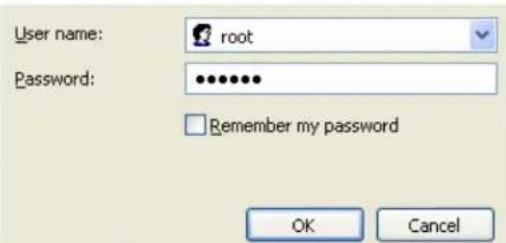
After connecting to the WMI, a pop-up dialog box would appear and request a username and password.
Enter the default username 'root' and password 'public' in the pop-up dialog box. After the successful authentication, the home page for WMI would appear.
text_image
User name: root Password: ••••••• Remember my password OK CancelFigure 2-1 Logging into Web Management Interface (WMI)
Note: During the log-in process, an option such as "Remember my password" may appear. If this option is enabled, one would not be required to re-enter the username or password when accessing the WMI next time. Please use this option with care.
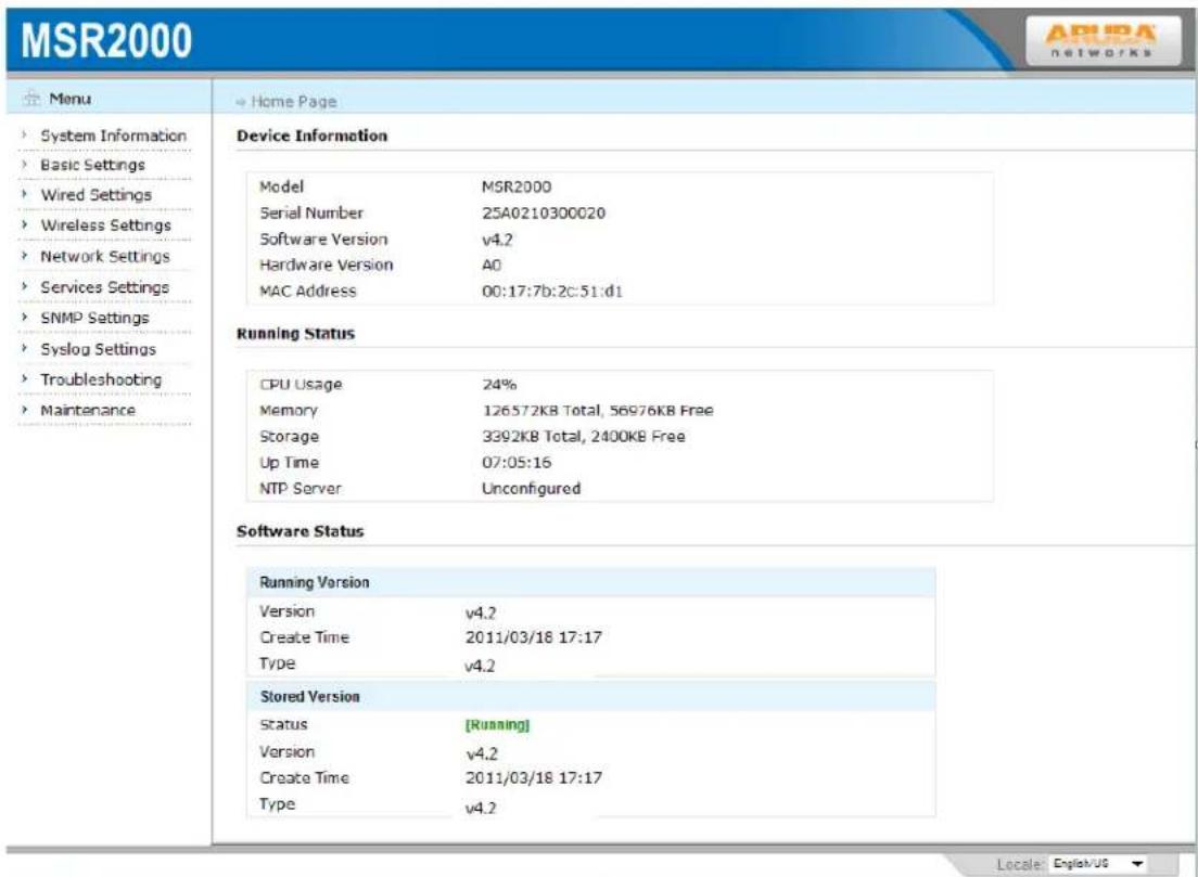
After successfully logging into the wireless mesh router web management interface, one is lead directly to the System Information as shown in figure below.
text_image
MSR2000 Menu System Information Basic Settings Wired Settings Wireless Settings Network Settings Services Settings SNMP Settings Syslog Settings Troubleshooting Maintenance Home Page Device Information Model MSR2000 Serial Number 25A0210300020 Software Version v4.2 Hardware Version A0 MAC Address 00:17:7b:2c:51:d1 Running Status CPU Usage 24% Memory 126572KB Total, 56976KB Free Storage 3392KB Total, 2400KB Free Up Time 07:05:16 NTP Server Unconfigured Software Status Running Version Version v4.2 Create Time 2011/03/18 17:17 Type v4.2 Stored Version Status [Running] Version v4.2 Create Time 2011/03/18 17:17 Type v4.2 Locale: English/U6Figure 2-2 Web Management Interface Home Page
2.1.2. WMI Basics
The WMI is composed of three components: the title banner (top), the menu tree (left), the configuration area (right), and the locale selector (bottom) as shown in figure below. The title banner shows the model name and the company Logo; the menu tree provides clear, hierarchical navigation to the various configuration areas. Clicking on one of the choices in the menu tree would cause the area on the right to display the specific configurable settings for that menu choice. The locale selector on the bottom allows users to change the current language and locale-specific style used by the WMI. Currently, US English and PRC Chinese are supported.
Chapter 3 Basic Settings
This chapter describes the basic settings to a wireless mesh router.
3.1. Basic Settings
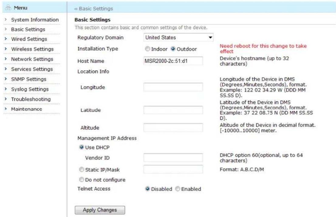
Clicking on the menu item "Basic Settings" leads the user to the basic settings area which allows the user to retrieve and edit configuration settings which take effect across the wireless mesh router. An example screen is shown in figure below.
text_image
Menu System Information Basic Settings Wired Settings Wireless Settings Network Settings Services Settings SNMP Settings Syslog Settings Troubleshooting Maintenance Basic Settings This section contains basic and common settings of the device. Regulatory Domain United States Installation Type Indoor Outdoor Need reboot for this change to take effect Host Name MSR2000-2c:51:d1 Device's hostname (up to 32 characters) Location Info Longitude Latitude Altitude Management IP Address Use DHCP Vendor ID Static IP/Mask Do not configure Telnet Access Disabled Enabled Altitude of the Device in decimal format. [-10000..10000] meter. DHCP option 60(optional, up to 64 characters) Format: A.B.C.D/M Apply ChangesFigure 3-1 Basic Configuration Screen
The table below describes basic settings configuration:
Table 3-1 Basic Settings Configuration
| Setting | Explanation | Default |
| Regulatory domain code | Selects the regulatory domain code. | United States |
| Installation Type | Selects the installation type: Indoor or Outdoor | For MSR1200, the default value is Indoor; for MSR2000, MSR4000 and MST200, the default is Outdoor |
| Hostname | Allows users to set the hostname of the MESH ROUTER product. Input a character string as the hostname. The character string shall include up to 32 | The name of MESH ROUTER product |
Aruba Mesh Router Web-based Configuration Guide
| letters and numbers and beginning with letter. | ||
| Location Info | Enter the longitude, latitude and altitude value of the device. | N/A |
| Management IP Address | 1) Use DHCP: Enter vendor ID, configure DHCP Option 60 (up to 64 characters)2) Static IP/mask: manually configure static IP/mask, format A.B.C.D/M3) Do not configure: not configure IP address | N/A |
| Telnet Access | Whether enable Telnet access | Disabled |
Saving Configuration for the Basic Settings
After editing the values for the above fields, one may save the changes by clicking the "Apply Changes" button.
Chapter 4 Configuring Ethernet Interface
Each wireless mesh router contains one physical Ethernet interface used to connect with a wired network or device. This chapter describes how the Ethernet interface is configured using Web-based Management.
4.1. Configuring Ethernet Interface Basic
Click the "Wired Settings" button in the menu to expand the sub-menu. Then, click the "Ethernet" button in the sub-menu to enter the Ethernet interface configuration page.
| Menu | Wired Settings > Ethernet | |||||
| System Information | Ethernet Ports | |||||
| Basic Settings | Configurable Ethernet interfaces that could connect the wireless mesh network with a wired network or device. | |||||
| Wired Settings | Name | IP Address/Mask | MAC Address | Admin Status | Physical Status | Description |
| Ethernet | Eth0 | 10.65.12.100/24 (Static) | 00:17:7b:2c:51:d1 Up | Up | ||
| Wireless Settings | ||||||
| Network Settings | ||||||
| Services Settings | ||||||
| SNMP Settings | ||||||
| Syslog Settings | ||||||
| Troubleshooting | ||||||
| Maintenance | ||||||
Figure 4-1 Ethernet Interface Screen
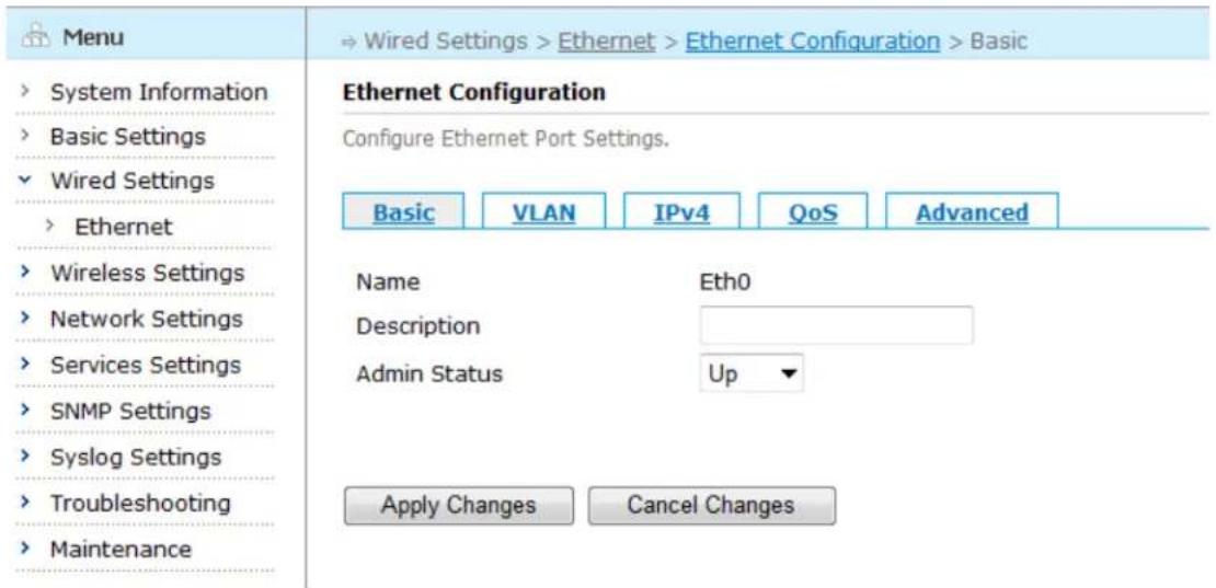
To configure an Ethernet interface, click its interface name "Eth0" to enter the basic configuration page.
text_image
Menu System Information Basic Settings Wired Settings Ethernet Wireless Settings Network Settings Services Settings SNMP Settings Syslog Settings Troubleshooting Maintenance Ethernet Configuration Configure Ethernet Port Settings. Basic VLAN IPv4 QoS Advanced Name Eth0 Description Admin Status Up Apply Changes Cancel ChangesFigure 4-2 Ethernet Interface Basic Configuration Screen
Table below describes the settings for the Ethernet interface basic.
Table 4-1 Ethernet Interface Basic Configuration Fields
| Setting | Explanation | Default |
| Description | Describe the Ethernet interface | N/A |
| Admin Status | Can be up or down.If down, this interface would be inactive (shutdown). | Up |
Saving Configuration for the Ethernet Interface Basic
To save the configuration after editing the above settings, click the "Apply Changes" button. To discard any changes and return to the previous page, click the "Cancel Changes" button.
4.2. Configuring Ethernet Interface VLAN
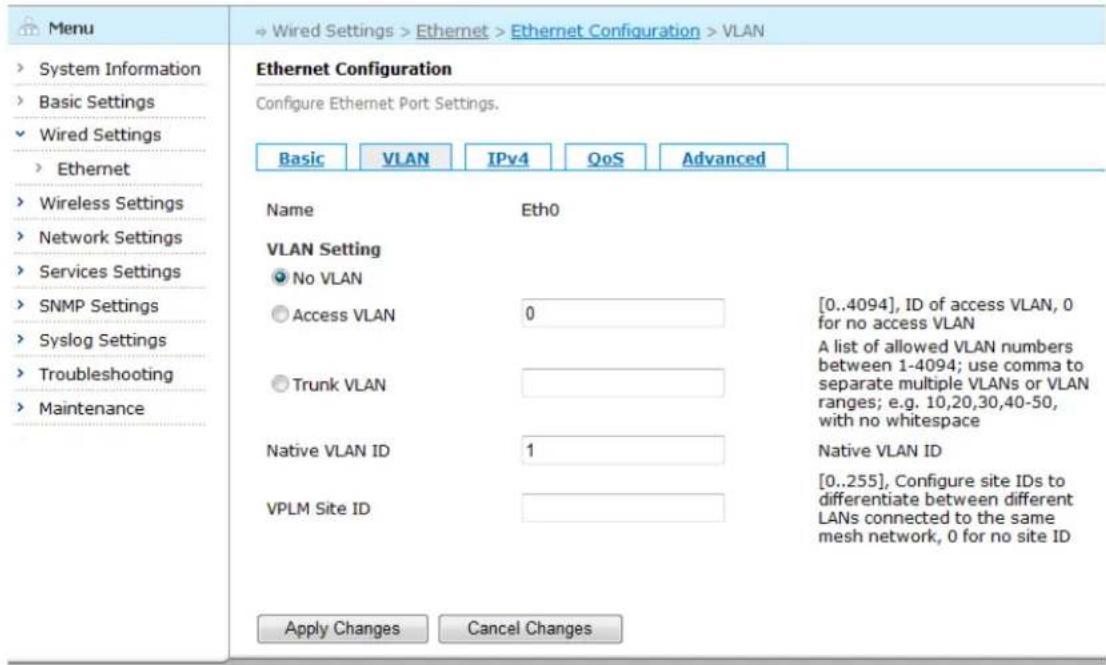
To configure the Ethernet interface VLAN, click the "VLAN" tab to enter the VLAN configuration page.
text_image
Menu System Information Basic Settings Wired Settings Ethernet Wireless Settings Network Settings Services Settings SNMP Settings Syslog Settings Troubleshooting Maintenance Ethernet Configuration Configure Ethernet Port Settings. Basic VLAN IPv4 QoS Advanced Name Eth0 VLAN Setting No VLAN Access VLAN 0 [0..4094], ID of access VLAN, 0 for no access VLAN Trunk VLAN A list of allowed VLAN numbers between 1-4094; use comma to separate multiple VLANs or VLAN ranges; e.g. 10,20,30,40-50, with no whitespace Native VLAN ID 1 Native VLAN ID VPLM Site ID [0..255], Configure site IDs to differentiate between different LANs connected to the same mesh network, 0 for no site ID Apply Changes Cancel ChangesFigure 4-3 Ethernet Interface VLAN Configuration Screen
Table below describes the settings for the Ethernet interface VLAN.
Table 4-2 Ethernet Interface VLAN Configuration Fields
| Setting | Explanation | Default |
| VLAN | 1) No VLAN;2) Access VLAN, configure the Ethernet interface as VLAN access port, and enter VLAN access ID;3) Trunk VLAN, configure the Ethernet interface as Trunk VLAN portNote: VLAN configuration is mutually exclusive with IP address configuration. If want to configure VLAN, please choose “Do not configure” in the IP address configuration section. | Trunk VLAN 1 |
Aruba Mesh Router Web-based Configuration Guide
| Native VLAN ID | When the Ethernet interface acts as Trunk port,configure its local VLAN. | 1 |
| VPLM Site ID | Configure a manual defined Ethernet domain ID. Used by VPLM for handling loop problem. | N/A |
Saving Configuration for the Ethernet Interface VLAN
To save the configuration after editing the above settings, click the "Apply Changes" button. To discard any changes and return to the previous page, click the "Cancel Changes" button.
Note: Change the VLAN setting may make the router inaccessible via Ethernet interface. Be careful to change this setting.
4.3. Configuring Ethernet Interface IPv4
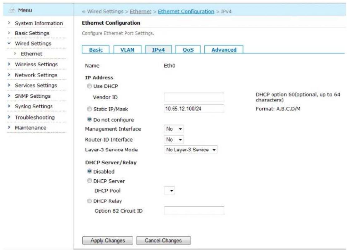
To configure the Ethernet interface IPv4, click the "IPv4" tab to enter the IPv4 edit page.
text_image
Menu System Information Basic Settings Wired Settings Ethernet Wireless Settings Network Settings Services Settings SNMP Settings Syslog Settings Troubleshooting Maintenance Ethernet Configuration Configure Ethernet Port Settings. Basic VLAN IPv4 QoS Advanced Name Eth0 IP Address Use DHCP Vendor ID DHCP option 60(optional, up to 64 characters) Static IP/Mask 10.65.12.100/24 Format: A.B.C.D/M Do not configure Management Interface No Router-ID Interface No Layer-3 Service Mode No Layer-3 Service DHCP Server/Relay Disabled DHCP Server DHCP Pool DHCP Relay Option 82 Circuit ID Apply Changes Cancel ChangesFigure 4-4 Ethernet Interface IPv4 Configuration Screen
Table below describes the settings for the Ethernet interface IPv4.
Table 4-3 Ethernet Interface IPv4 Configuration Fields
| Setting | Explanation | Default |
| IP Address | 1) Use DHCP: Enter manufacturer ID, configure DHCP Option 60 (up to 64 characters)2) Static IP/mask: manually configure static IP/mask, format A.B.C.D/M3) Do not configure: not configure IP address | Do not configure |
| Management Interface | Yes: Configure the Ethernet interface as management interface.No: Cancel the configuration of the Ethernet interface as management interface. | No |
| Router-ID Interface | Yes: Configure the Ethernet interface as Router-ID interface.No: Cancel the configuration of the Ethernet interface as Router-ID interface. | No |
| Layer-3 Service | Configure the layer-3 working mode at this interface, including 4 options:No layer-3 service: Not enable layer-3 mode;Layer-3 access: Enable layer-3 access mode;Layer-3 gateway: Enable layer-3 gateway mode;Layer-3 backhaul: Enable layer-3 backhaul mode; | No layer-3 service |
| DHCP Server/Relay | 1) Disabled2) DHCP ServerDHCP Pool: configure DHCP address pool3) DHCP RelayOption 82 Circuit ID configuration | Disabled |
Saving Configuration for the Ethernet Interface IPv4
To save the configuration after editing the above settings, click the "Apply Changes" button. To discard any changes and return to the previous page, click the "Cancel Changes" button.
Note: Change IP address from "Static" or "Use DHCP" to "Do not configure" may make the router inaccessible via Ethernet interface. Be careful to change this setting.
4.4. Configuring Ethernet Interface QoS
To configure the Ethernet interface QoS, click the "QoS" tab to enter the QoS edit page.

text_image
Menu System Information Basic Settings Wired Settings Ethernet Wireless Settings Network Settings Services Settings SNMP Settings Syslog Settings Troubleshooting Maintenance Ethernet Configuration Configure Ethernet Port Settings. Basic VLAN IPv4 QoS Advanced Name Eth0 Access Category None None 0 Best Effort (BE) 1 Background (BK) 2 Standard (ST) 3 Excellent Effort (EE) 4 Control Load (CL) 5 Video Traffic (VI) 6 Voice Traffic (VO) 7 Network Control (NC) Apply Changes CancelFigure 4-5 Ethernet Interface QoS Configuration Screen
Table below describes the settings for the Ethernet interface QoS.
Table 4-4 Ethernet Interface QoS Configuration Fields
Aruba Mesh Router Web-based Configuration Guide
| Setting | Explanation | Default |
| Access-Category Mapping | Configure the mapping relations of QoS priorities | None |
Saving Configuration for the Ethernet Interface QoS
To save the configuration after editing the above settings, click the "Apply Changes" button. To discard any changes and return to the previous page, click the "Cancel Changes" button.
4.5. Ethernet Interface Advanced Configuration
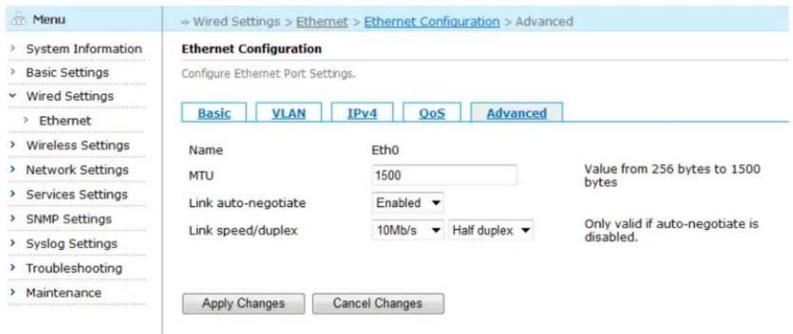
To configure the Ethernet interface advanced features, click the "Advanced" tab to enter the Advanced edit page.
text_image
Menu System Information Basic Settings Wired Settings Ethernet Wireless Settings Network Settings Services Settings SNMP Settings Syslog Settings Troubleshooting Maintenance Ethernet Configuration Configure Ethernet Port Settings. Basic VLAN IPv4 QoS Advanced Name Eth0 MTU 1500 Value from 256 bytes to 1500 bytes Link auto-negotiate Enabled Link speed/duplex 10Mb/s Half duplex Only valid if auto-negotiate is disabled. Apply Changes Cancel ChangesFigure 4-6 Ethernet Interface Advanced Configuration Screen
Table below describes the settings for the Ethernet interface advanced features.
Table 4-5 Ethernet Interface Advanced Configuration Fields
| Setting | Explanation | Default |
| MTU (Maximum Transmission Unit) | Maximum transmission unit in bytes; controls how Layer-3 packets would be fragmented when they are sent through this interface. Range: 256-1500 | 1500 |
| Link Auto-negotiate | Whether enable link auto negotiation mode at the Ethernet interface | Enable |
| Link Speed/Duplex | Set the Ethernet interface at force speed and duplex mode.10/100/1000 means the Ethernet interface speed is set at 10Mbps/100Mbps/1000Mbps;full|half means the duplex mode of Ethernet interface is full/half duplex | 10Mb/s, Half duplex |
Saving Configuration for the Ethernet Interface Advanced
To save the configuration after editing the above settings, click the "Apply Changes" button. To discard any changes and return to the previous page, click the "Cancel Changes" button.
Chapter 5 Wireless Settings
Dot11Radio interfaces on the wireless mesh routers are used for connecting with 802.11-compatible client devices. This chapter contains the following content:
• Radio Interface Configuration
• BSS Interface Configuration
- Mesh Configuration
- Client Mode Configuration
5.1. Radio Interfaces Configuration
Click the "Radio" item in the "Wireless Settings" sub-menu to enter the Radio interface configuration page. The resulting page displays the router's physical radio interfaces in a list, as shown in figure below.
| Menu | Wireless Settings > Radio | ||||
| System Information Basic Settings Wired Settings Wireless Settings Radio BSS Mesh Client Mode Network Settings Services Settings SNMP Settings Syslog Settings Troubleshooting Maintenance | Radio Settings Configure physical wireless parameters for each radio of the node. □ Radio Mode/Channel Status TX Power Antenna Gain □ Radio 0 802.11na 20Mhz 149 (Manual) Up 21dBm 0db □ Radio 1 802.11na 20Mhz 149 (Manual) Up 21dBm 0db Restart Selected Radio(s) | ||||
Figure 5-1 Radio Interfaces Screen
5.1.1. Configuring Radio Interface Basic
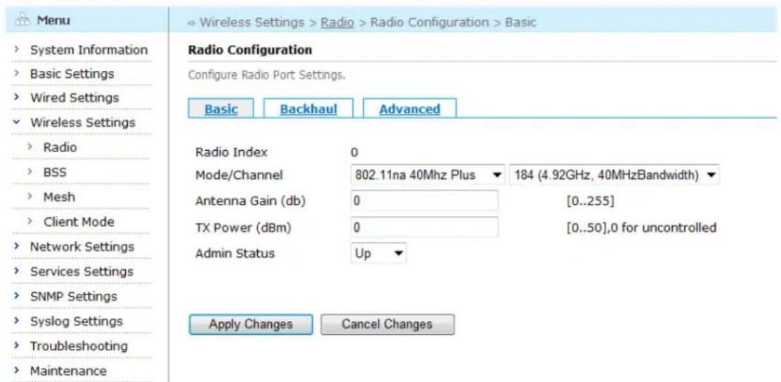
To view or change the configuration for a particular radio, click the name of the radio interface (i.e. "Radio 0" in Figure above). The resulting page displays the basic configuration settings and allows them to be changed.
text_image
Menu System Information Basic Settings Wired Settings Wireless Settings Radio BSS Mesh Client Mode Network Settings Services Settings SNMP Settings Syslog Settings Troubleshooting Maintenance Radio Configuration Configure Radio Port Settings. Basic Backhaul Advanced Radio Index 0 Mode/Channel 802.11na 40Mhz Plus 184 (4.92GHz, 40MHzBandwidth) Antenna Gain (db) 0 [0..255] TX Power (dBm) 0 [0..50],0 for uncontrolled Admin Status Up Apply Changes Cancel ChangesFigure 5-2 Radio Interface Basic Configuration Screen
Table below describes the settings for radio interface basic.
Table 5-1 Radio Interface Basic Configuration Fields
| Setting | Explanation | Default |
| Radio Index | 0, means Radio0 interface | |
| Mode/Channel | Configure the wireless settings of this radio interface manually.mode: a, b, g or g-only, na,ng,na-ht40plus,na-ht40minus,ng-ht40plus,ng-ht40minusa: Use 802.11ab: Use 802.11bg: Use 802.11g; compatible with 802.11bg-only: Use 802.11 g-only, don't compatible with 802.11b;na: Use 802.11na and the bandwidth of each channel is 20MHzng: Use 802.11ng and the bandwidth of each channel is 20MHzna-ht40plus: Use 802.11na, combining two neighboring 20MHz channels into one 40MHz channel. The control channel is the configured channel, and the frequency of the extension channel is higher than that of the control channel.na-ht40minus: Use 802.11na, combining two neighboring 20MHz channels into one 40MHz channel. The control channel is the configured channel, and the frequency of the extension channel is lower than that of the master channel.ng-ht40plus: Use 802.11ng, combining two neighboring | For radio0, the default Mode/Channel is 802.11na 40Mhz Plus, 184 (4.92GHz, 40MHz Bandwidth); for radio1, the default is 802.11g, 1(2.412GHz, 20MHz Bandwidth) |
Aruba Mesh Router Web-based Configuration Guide
| 20MHz channels into one 40MHz channel. The control channel is the configured channel, and the frequency of the extension channel is higher than that of the control channel.ng-ht40minus: Use 802.11ng, combining two neighboring 20MHz channels into one 40MHz channel. The control channel is the configured channel, and the frequency of the extension channel is lower than that of the control channel.Note: g mode is compatible with 802.11b mode; g-only mode is not compatible with the 802.11b mode. ng, ng-ht40plus, ng-ht40minus mode is compatible with 802.11g; na,na-ht40plus,na-ht40minus mode is compatible with 802.11a.By default, the MSR/MSA only support 802.11b/g, other modes need license.Channel: Channel setting is optional. A channel number must be allowed by the device's country/regulatory domain code.China supports Channel 1-13 in 2.4GIf not configured, the system will choose the first legal channel number of the country/regulatory domain code. | ||
| Antenna Gain | Configure antenna gain, the range of value is 0-255This parameter is usually set at deployment time and shall be changed with caution. | 0 |
| Tx Power | Configure Radio's Tx power in dbm. The maximum parameter that can be configured is determined by the Tx power of the radio interface.0 means restore Radio's Tx power to the default.This parameter shall be changed with caution | 0 |
| Admin Status | Can be up or down.If down, this interface would be inactive (shutdown).If up, this interface would be active. | Up |
Saving Configuration for the Radio Interface Basic
To save the configuration after editing the above settings, click the "Apply Changes" button. To discard any changes and return to the previous page, click the "Cancel Changes" button.
5.1.2. Configuring Radio Interface Backhaul
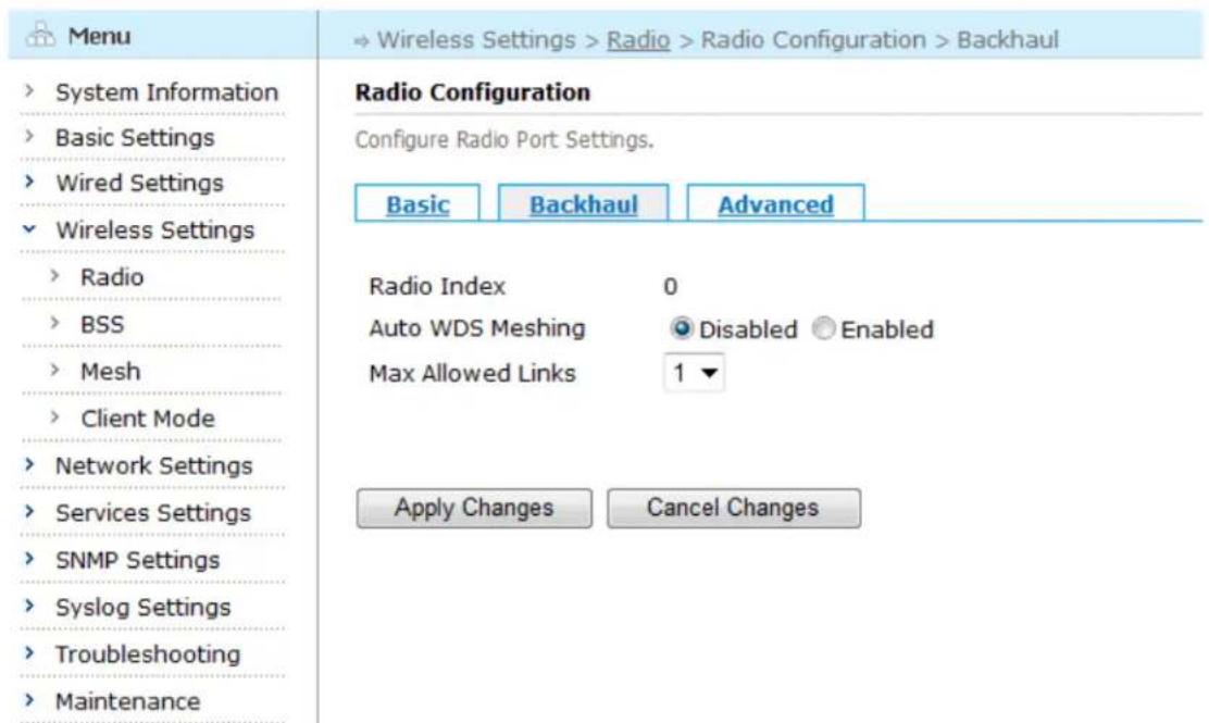
Click the "Backhaul" tab to enter the Backhaul configuration page.
text_image
Menu System Information Basic Settings Wired Settings Wireless Settings Radio BSS Mesh Client Mode Network Settings Services Settings SNMP Settings Syslog Settings Troubleshooting Maintenance Radio Configuration Configure Radio Port Settings. Basic Backhaul Advanced Radio Index 0 Auto WDS Meshing Disabled Enabled Max Allowed Links 1▼ Apply Changes Cancel ChangesFigure 5-3 Radio Interface Backhaul Configuration Screen
Table below describes the settings for Radio interface Backhaul Parameters.
Table 5-2 Radio Interface Backhaul Configuration Fields
| Setting | Explanation | Default |
| Radio Index | 0, means Radio0 interface | N/A |
| Auto WDS Meshing | Enabled or disable Auto WDS Meshing | For radio 0, the default is Disabled; for radio 1, the default is Enabled |
| Max Allowed Links | Configure the maximum allowed links (1-6) on this radio interface | 1 |
Saving Configuration for the Radio Interface Backhaul
To save the configuration after editing the above settings, click the "Apply Changes" button. To discard any changes and return to the previous page, click the "Cancel Changes" button.
5.1.3. Configuring Radio Interface Advanced Settings
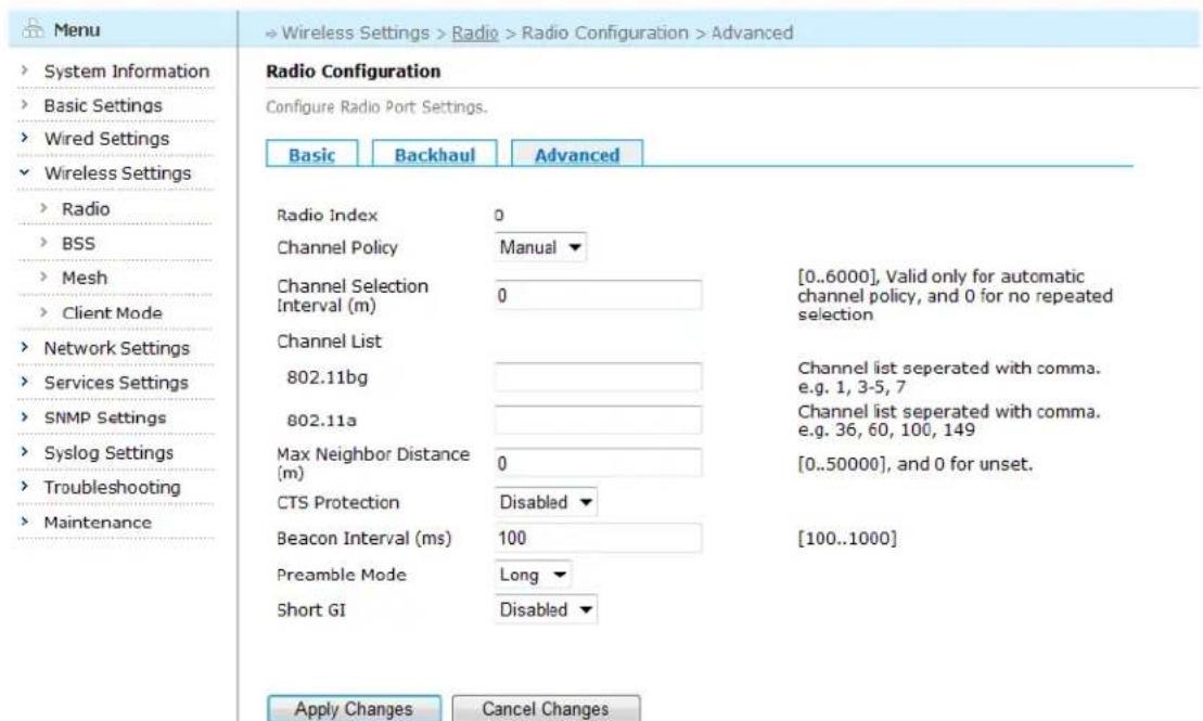
Click the "Advanced" tab to enter the Advanced configuration page.
text_image
Menu System Information Basic Settings Wired Settings Wireless Settings Radio BSS Mesh Client Mode Network Settings Services Settings SNMP Settings Syslog Settings Troubleshooting Maintenance Radio Configuration Configure Radio Port Settings. Basic Backhaul Advanced Radio Index 0 Channel Policy Manual Channel Selection 0 [0..6000], Valid only for automatic Interval (m) Channel List 802.11bg Channel list seperated with comma. e.g. 1, 3-5, 7 802.11a Channel list seperated with comma. e.g. 36, 60, 100, 149 Max Neighbor Distance 0 [0..50000], and 0 for unset. CTS Protection Disabled Beacon Interval (ms) 100 [100..1000] Preamble Mode Long Short GI Disabled Apply Changes Cancel ChangesFigure 5-4 Radio Interface RF Scan Configuration Screen
Table below describes the settings for Radio interface Advanced features.
Table 5-3 Radio Interface Advanced Configuration Fields
| Setting | Explanation | Default |
| Radio Index | 0, means Radio0 interface | N/A |
| Channel Policy | Configure channel policy of radio interface.Auto: according to the scanning result of the current frequency (2.4GHz or 5GHz), the system automatically choose the channel with minimum interference as the Radio's working channel.Manual: the system chooses the manually configured channel as the Radio's working channel. | Manual |
| Channel Selection Interval (m) | Only valid under auto channel selection mode, the valid value is 1-6000 minutes or 0 as no repeat selection. | 0 |
| Channel List | Configure the working frequency and channel list of the Radio interface.1) 802.11bg: configure 802.11bg channel list, separated with comma;2) 802.11a: configure 802.11a channel list, separated with comma; | N/A |
| Max Neighbor Distance | Configure the maximum distance between two neighbor nodes, value from 1 to 50000 meters. 0 for unset. | 0 |
| CTS Protection | Enable/disable CTS protection for handling of a mix of 802.11b and 802.11g clients.This parameter is usually set at deployment time and rarely needs to change. | Disabled |
| Beacon Interval | Configure the milliseconds between each time of sending beacon from this radio interface (100-1000 milliseconds) | 100 |
| Preamble Mode | Preamble: part of the packet head, including the information needed when AP and client receiving or sending packet. Short: to improve throughput. Long: to compatible with the client that only support long preamble. | Long |
| Short GI | This setting is used to enable the short interval feature of the radio interface under 802.11n mode (needs license). If the multipath effect is not obvious, this setting can adjust the Tx interval of signals from 800ns to 400ns, improving the throughput. Note: If the multipath effect is obvious, it's not recommended to use this setting. | Disabled |
Saving Configuration for the Radio Interface Advanced
To save the configuration after editing the above settings, click the "Apply Changes" button. To discard any changes and return to the previous page, click the "Cancel Changes" button.
5.2. BSS Interfaces Configuration
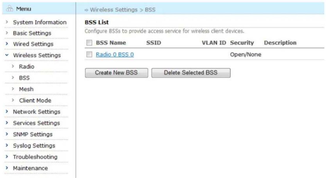
Click "Wireless Settings" > "BSS" listed in the main menu tree. The resulting page shows the configuration and status of all BSSs on the device.
text_image
Menu System Information Basic Settings Wired Settings Wireless Settings Radio BSS Mesh Client Mode Network Settings Services Settings SNMP Settings Syslog Settings Troubleshooting Maintenance BSS List Configure BSSs to provide access service for wireless client devices. BSS Name SSID VLAN ID Security Description Radio 0 BSS 0 Open/None Create New BSS Delete Selected BSSFigure 5-5 BSS List Page
In this page, users could create a new BSS as well as configure or delete an existing BSS.
5.2.1. Creating a New BSS/Entering an Existing BSS
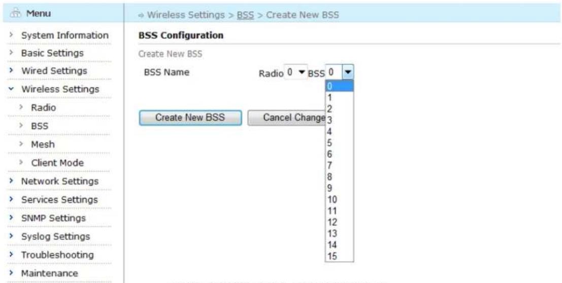
To create a new BSS, click the "Create New BSS" button in the BSS list page. The "Create New BSS" page appears.
text_image
Menu System Information Basic Settings Wired Settings Wireless Settings Radio BSS Mesh Client Mode Network Settings Services Settings SNMP Settings Syslog Settings Troubleshooting Maintenance → Wireless Settings > BSS > Create New BSS BSS Configuration Create New BSS BSS Name Radio 0 ▼ BSS 0 ▼ Create New BSS Cancel Change 0 1 2 3 4 5 6 7 8 9 10 11 12 13 14 15Figure 5-6 Creating a New BSS Page
Select radio interface and BSS ID from the drop-down menu and click "Create New BSS" button to enter BSS configuration page; click "Cancel Changes" button to discard any changes and return to the previous page.
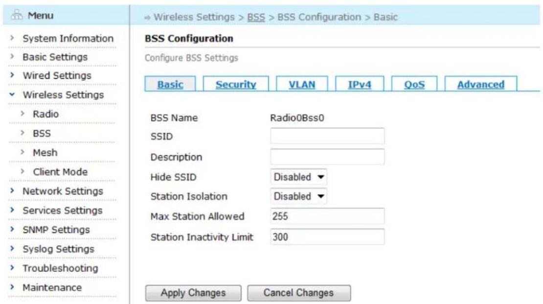
After clicking "Create New BSS" button, the BSS basic configuration page for the new created BSS will appear, as shown in figure below:
text_image
Menu System Information Basic Settings Wired Settings Wireless Settings Radio BSS Mesh Client Mode Network Settings Services Settings SNMP Settings Syslog Settings Troubleshooting Maintenance BSS Configuration Configure BSS Settings Basic Security VLAN IPv4 QoS Advanced BSS Name Radio0Bss0 SSID Description Hide SSID Disabled Station Isolation Disabled Max Station Allowed 255 Station Inactivity Limit 300 Apply Changes Cancel ChangesFigure 5-7 Basic Configuration Screen for a New Created BSS
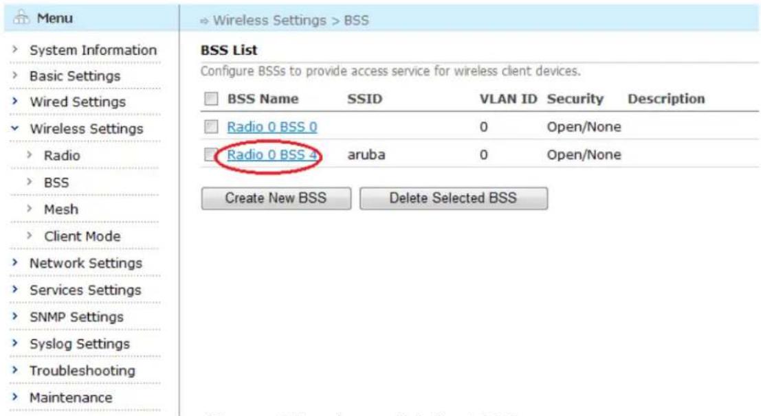
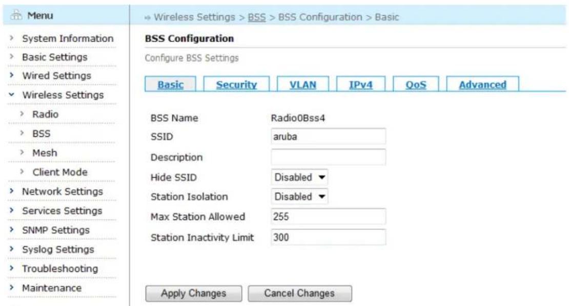
To enter an existing BSS, click its BSS Name to enter the BSS configuration page.
text_image
Menu System Information Basic Settings Wired Settings Wireless Settings Radio BSS Mesh Client Mode Network Settings Services Settings SNMP Settings Syslog Settings Troubleshooting Maintenance BSS List Configure BSSs to provide access service for wireless client devices. BSS Name SSID VLAN ID Security Description Radio 0 BSS 0 0 Open/None Radio 0 BSS 4 aruba 0 Open/None Create New BSS Delete Selected BSSFigure 5-8 Entering an Existing BSS Page
text_image
Menu System Information Basic Settings Wired Settings Wireless Settings Radio BSS Mesh Client Mode Network Settings Services Settings SNMP Settings Syslog Settings Troubleshooting Maintenance BSS Configuration Configure BSS Settings Basic Security VLAN IPv4 QoS Advanced BSS Name Radio0Bss4 SSID aruba Description Hide SSID Disabled Station Isolation Disabled Max Station Allowed 255 Station Inactivity Limit 300 Apply Changes Cancel ChangesFigure 5-9 Basic Configuration Screen for an Existing BSS
5.2.2. Configuring a New Created BSS/an Existing BSS
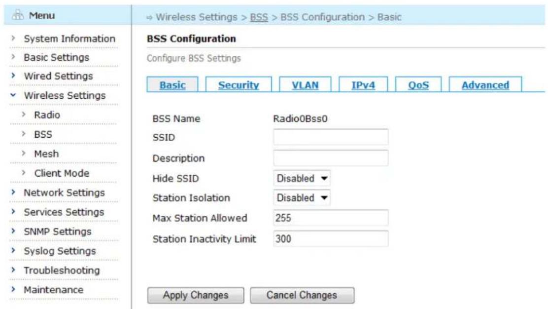
To configure a new created BSS/an existing BSS, enter the BSS configuration page as stated above.
text_image
Menu System Information Basic Settings Wired Settings Wireless Settings Radio BSS Mesh Client Mode Network Settings Services Settings SNMP Settings Syslog Settings Troubleshooting Maintenance BSS Configuration Configure BSS Settings Basic Security VLAN IPv4 QoS Advanced BSS Name Radio0Bss0 SSID Description Hide SSID Disabled # Station Isolation Disabled # Max Station Allowed 255 Station Inactivity Limit 300 Apply Changes Cancel ChangesFigure 5-10 BSS Basic Configuration Screen
Table below describes the BSS basic settings in this page.
Table 5-4 BSS Basic Configuration Fields
| Setting | Explanation | Default |
| BSS Name | Display the BSS's Radio interface and BSS ID. Each radio supports up to 16 BSS | N/A |
| SSID | The 802.11 SSID for this BSS | N/A |
| Description | Describe the BSS | N/A |
| Hide SSID | Enable: not broadcast SSID. Clients can't scan out the SSID. If a client needs to connect to this BSS, it needs to specify this SSID.Disable: broadcast SSID and allow this BSS's SSID broadcast to the air periodically. Clients can scan out the SSID. | Disabled |
| Station Isolation | Enabled: prevent the stations under this BSS from communicating with each other.Disabled: not prevent the stations under this BSS from communicating with each other. | Disabled |
| Max Station Allowed | The maximum number (1-255) of clients that would be allowed to associate with this BSS | 255 |
| Station Inactivity Limit | Configure the maximum amount of time (15-65535 seconds) a station/client is allowed to be inactive before the inactivity policy takes effect. If in the configured time, BSS doesn't receive the data from client, BSS will disassociate with the client. | 300 |
Saving configuration for BSS Basic Configuration
To save the configuration after editing the above settings, click the "Apply Changes" button. To discard any changes and return to the previous page, click the "Cancel Changes" button.
5.2.3. Configuring BSS Security
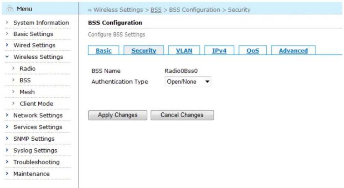
BSS supports 802.11 security standards. By clicking the "Security" tab in the BSS Configuration page, enter the Security page. Choose Open WEP, Shared WEP, WPA, WPA2 from the dropdown menu besides the "Authentication Type" to enter the security configuration page.
Note: if choose Open/None from the drop-down menu besides "Authentication Type", no security configuration page appears.
text_image
Menu System Information Basic Settings Wired Settings Wireless Settings Radio BSS Mesh Client Mode Network Settings Services Settings SNMP Settings Syslog Settings Troubleshooting Maintenance BSS Configuration Configure BSS Settings Basic Security VLAN IPv4 QoS Advanced BSS Name Radio0Bss0 Authentication Type Open/None ▼ Apply Changes Cancel ChangesFigure 5-11 Authentication Configuration Screen
Open WEP
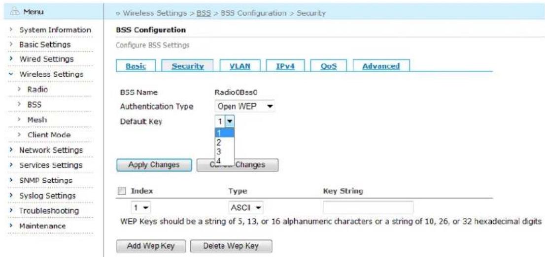
By clicking the drop down button beside the "Authentication Type" in the BSS Configuration page, choose Open WEP to enter the security configuration page.
text_image
Menu System Information Basic Settings Wired Settings Wireless Settings Radio BSS Mesh Client Mode Network Settings Services Settings SNMP Settings Syslog Settings Troubleshooting Maintenance Wireless Settings > BSS > BSS Configuration > Security BSS Configuration Configure BSS Settings Basic Security VLAN IPv4 QoS Advanced BSS Name RadioOBss0 Authentication Type Open WEP Default Key 1 1 2 3 Apply Changes Correct Changes Index Wayes String 1 ASCII WEP Keys should be a string of 5, 13, or 16 alphanumeric characters or a string of 10, 26, or 32 hexadecimal digits Add Wep Key Delete Wep KeyFigure 5-12 WEP Configuration Page
In WEP encryption mode, the user can configure up to 4 keys and specify one of them as default key.
Shared WEP
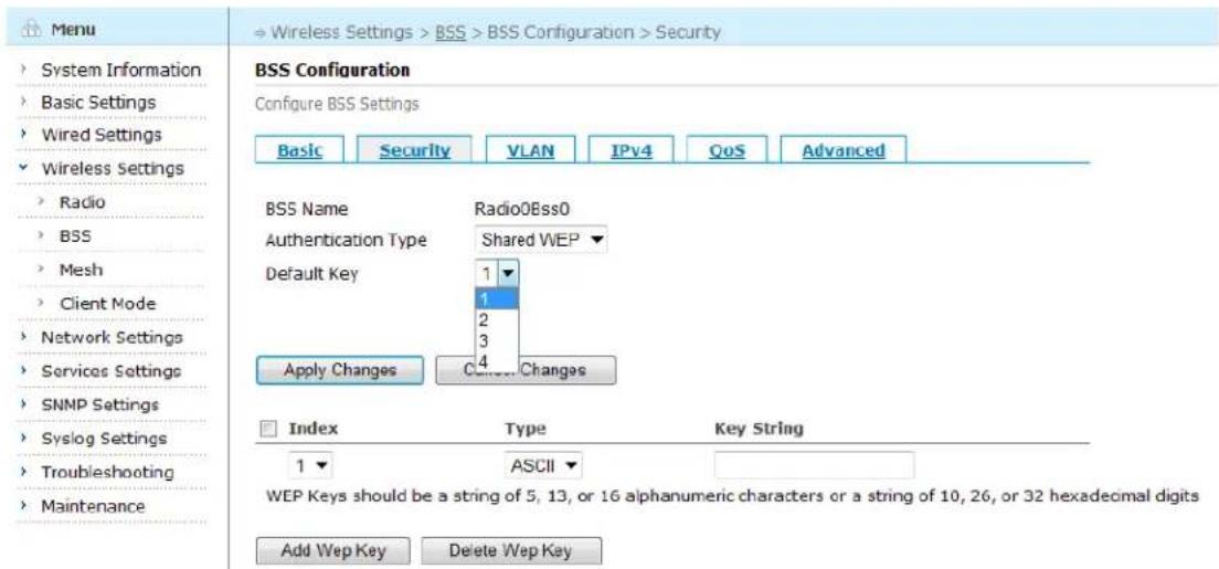
By clicking the drop down button beside the "Authentication Type" in the BSS Configuration page, choose Shared WEP to enter the security configuration page.
text_image
Menu System Information Basic Settings Wired Settings Wireless Settings Radio BSS Mesh Client Mode Network Settings Services Settings SNMP Settings Syslog Settings Troubleshooting Maintenance → Wireless Settings > BSS > BSS Configuration > Security BSS Configuration Configure BSS Settings Basic Security VLAN IPv4 QoS Advanced BSS Name Radio0Bss0 Authentication Type Shared WEP ▼ Default Key 1▼ Apply Changes Cancel Changes Index Way Key String 1▼ ASCII ▼ WEP Keys should be a string of 5, 13, or 16 alphanumeric characters or a string of 10, 26, or 32 hexadecimal digits Add Wep Key Delete Wep KeyFigure 5-13 WEP Configuration Page
In WEP encryption mode, the user can configure up to 4 keys and specify one of them as default key.
WPA
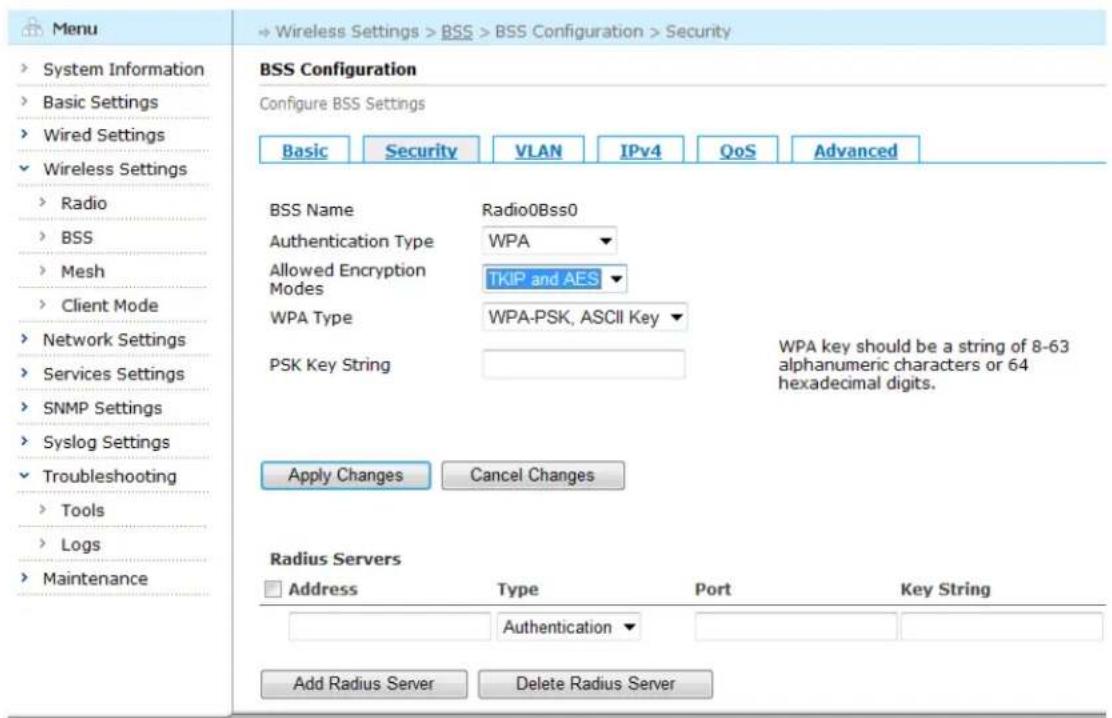
By clicking the drop down button beside the "Authentication Type" in the BSS Configuration page, Aruba Mesh Router Web-based Configuration Guide
choose WPA to enter the security configuration page.
text_image
Menu System Information Basic Settings Wired Settings Wireless Settings Radio BSS Mesh Client Mode Network Settings Services Settings SNMP Settings Syslog Settings Troubleshooting Tools Logs Maintenance BSS Configuration Configure BSS Settings Basic Security VLAN IPv4 QoS Advanced BSS Name Radio0Bss0 Authentication Type WPA Allowed Encryption TKIP and AES Modes WPA Type WPA-PSK, ASCII Key PSK Key String WPA key should be a string of 8-63 alphanumeric characters or 64 hexadecimal digits. Apply Changes Cancel Changes Radius Servers Address Type Port Key String Authentication Add Radius Server Delete Radius ServerFigure 5-14 WPA Configuration Page
Table below describes the WPA settings in this page.
Table 5-5 WPA Configuration Fields
| Setting | Explanation | Default |
| BSS Name | Display the BSS's Radio interface and BSS ID. Each radio supports up to 16 BSS | N/A |
| Authentication Type | Choose WPA | N/A |
| Allowed Encryption Modes | Choose WPA encryption modes:1) AES Only: choose AES encryption mode;2) TKIP Only: choose TKIP encryption mode;3) TKIP and AES: choose TKIP and AES encryption mode | TKIP and AES |
| WPA Type | Choose WPA Type:1) WPA-PSK, ASCII Key;2) WPA-PSK, Hex Key;3) WPA-Radius and needs to configure Radius server. | WPA-PSK, ASCII Key |
| PSK Key String | ASCII code or hexadecimal key. The length of ASCII code is 8-63; the length of Hex is 64. | N/A |
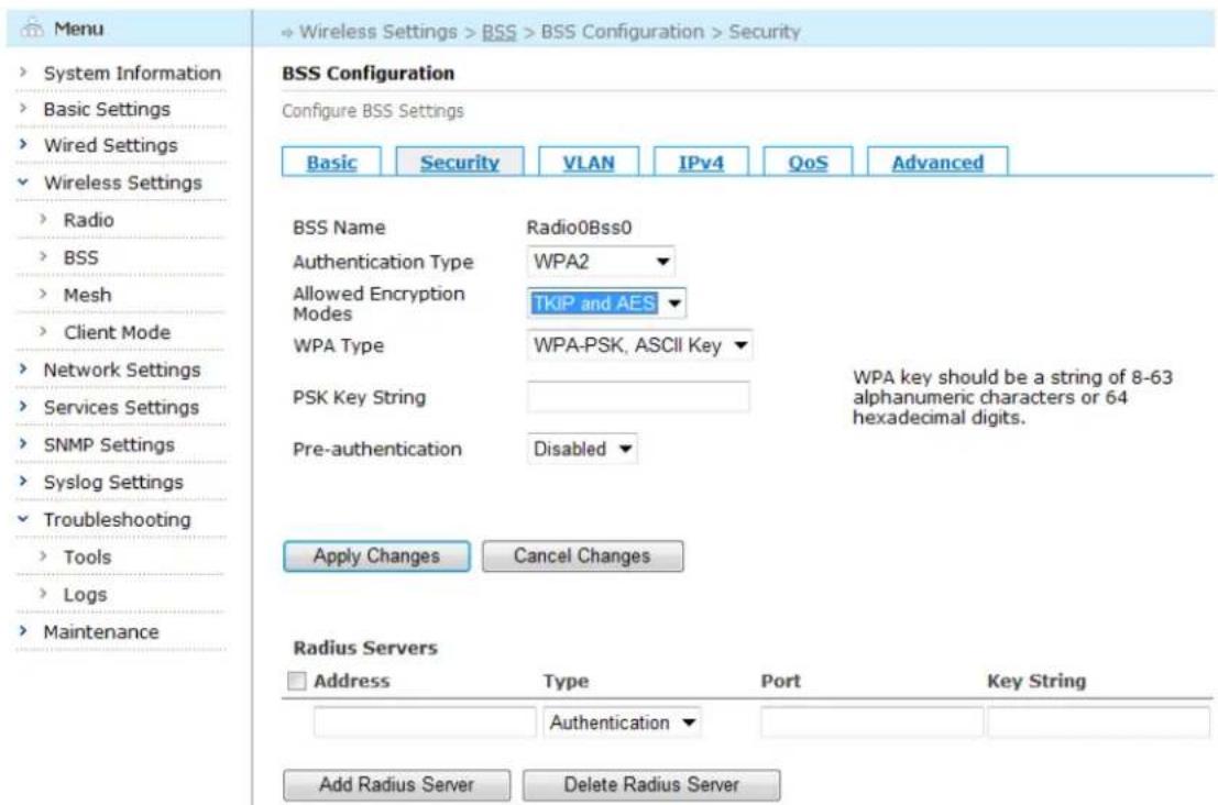
WPA2
By clicking the drop down button beside the "Authentication Type" in the BSS Configuration page, choose WPA2 to enter the security configuration page.
Aruba Mesh Router Web-based Configuration Guide
text_image
Menu System Information Basic Settings Wired Settings Wireless Settings Radio BSS Mesh Client Mode Network Settings Services Settings SNMP Settings Syslog Settings Troubleshooting Tools Logs Maintenance BSS Configuration Configure BSS Settings Basic Security VLAN IPv4 QoS Advanced BSS Name Radio0Bss0 Authentication Type WPA2 Allowed Encryption TKIP and AES Modes WPA Type WPA-PSK, ASCII Key PSK Key String WPA key should be a string of 8-63 alphanumeric characters or 64 hexadecimal digits. Pre-authentication Disabled Apply Changes Cancel Changes Radius Servers Address Type Port Key String Authentication Add Radius Server Delete Radius ServerFigure 5-15 WPA2 Configuration Page
Table below describes the WPA2 settings in this page.
Table 5-6 WPA Configuration Fields
| Setting | Explanation | Default |
| BSS Name | Display the BSS's Radio interface and BSS ID. Each radio supports up to 16 BSS | N/A |
| Authentication Type | Choose WPA2 | N/A |
| Allowed Encryption Modes | Choose WPA2 encryption modes:4) AES Only: choose AES encryption mode;5) TKIP Only: choose TKIP encryption mode;6) TKIP and AES: choose TKIP and AES encryption mode; | TKIP and AES |
| WPA Type | Choose WPA2 Type:1) WPA-PSK, ASCII Key;2) WPA-PSK, Hex Key;3) WPA-Radius and needs to configure Radius server. | WPA-PSK, ASCII Key |
| PSK Key String | ASCII code or hexadecimal key. The length of ASCII code is 8-63; the length of Hex is 64. | N/A |
| Pre-authentication | Enable or disable pre-authentication | Disabled |
Saving configuration for BSS Security
To save the configuration after editing the above settings, click the "Apply Changes" button. To discard any changes and return to the previous page, click the "Cancel Changes" button.
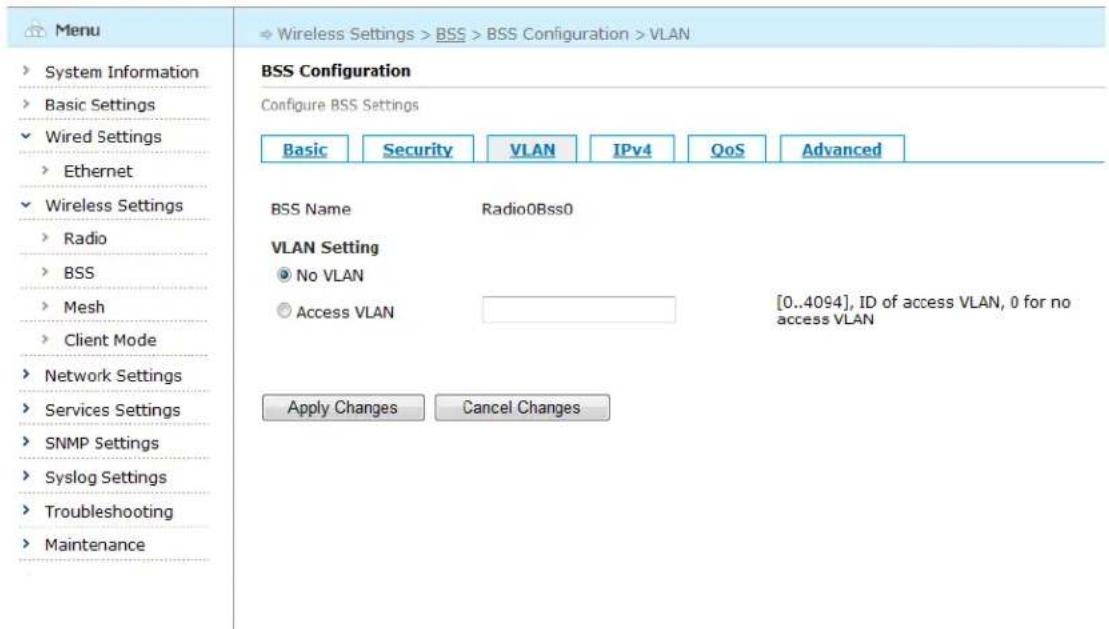
5.2.4. Configuring BSS VLAN
Click the "VLAN" tab to enter the VLAN configuration page.
text_image
Menu System Information Basic Settings Wired Settings Ethernet Wireless Settings Radio BSS Mesh Client Mode Network Settings Services Settings SNMP Settings Syslog Settings Troubleshooting Maintenance BSS Configuration Configure BSS Settings Basic Security VLAN IPv4 QoS Advanced BSS Name Radio0Bss0 VLAN Setting No VLAN Access VLAN [0..4094], ID of access VLAN, 0 for no access VLAN Apply Changes Cancel ChangesFigure 5-16 VLAN Configuration Screen
Table below describes the VLAN settings for BSS interface.
Table 5-7 BSS VLAN Configuration Fields
| Setting | Explanation | Default |
| BSS Name | Display the BSS's Radio interface and BSS ID. Each radio supports up to 16 BSS | N/A |
| VLAN Setting | No VLAN: the BSS doesn't belong to any VLAN;Access VLAN: the BSS belongs to a VLAN. The value range is 1-4094 | No VLAN |
Saving configuration for BSS VLAN
To save the configuration after editing the above settings, click the "Apply Changes" button. To discard any changes and return to the previous page, click the "Cancel Changes" button.
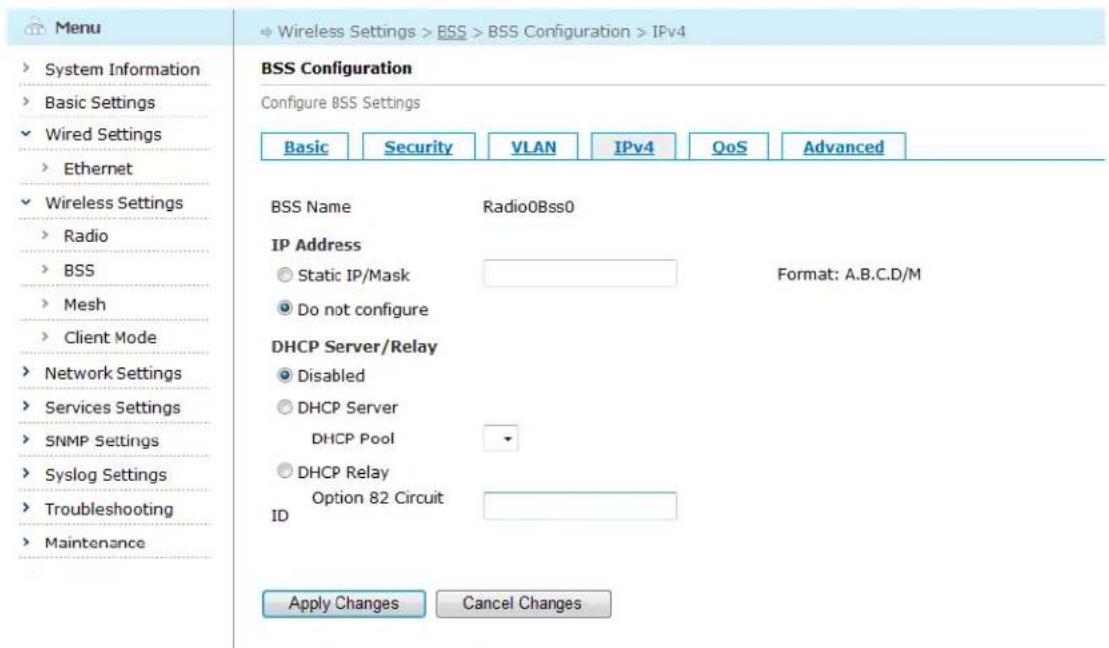
5.2.5. Configuring BSS IPv4
Click the "IPv4" tab to enter the IPv4 configuration page.
text_image
Menu System Information Basic Settings Wired Settings Ethernet Wireless Settings Radio BSS Mesh Client Mode Network Settings Services Settings SNMP Settings Syslog Settings Troubleshooting Maintenance BSS Configuration Configure BSS Settings Basic Security VLAN IPv4 QoS Advanced BSS Name Radio0Bss0 IP Address Static IP/Mask Format: A.B.C.D/M Do not configure DHCP Server/Relay Disabled DHCP Server DHCP Pool DHCP Relay Option 82 Circuit ID Apply Changes Cancel ChangesFigure 5-17 IPv4 Configuration Screen
Table below describes the IPv4 settings for BSS interface.
Table 5-8 BSS IPv4 Configuration Fields
| Setting | Explanation | Default |
| BSS Name | Display the BSS's Radio interface and BSS ID. Each radio supports up to 16 BSS | N/A |
| IP Address | Configure the IPv4 address for this BSS:1) Static IP address/Mask, format: A.B.C.D/M2) Do not configure | Do not configure |
| DHCP Server/Relay | Configure DHCP server/relay:1) Disabled2) Configure DHCP pool of DHCP Server3) Configure DHCP relay Option 82 | Disabled |
Saving configuration for BSS IPv4
To save the configuration after editing the above settings, click the "Apply Changes" button. To discard any changes and return to the previous page, click the "Cancel Changes" button.
5.2.6. Configuring BSS QoS
Click the "QoS" tab to enter the QoS configuration page.

text_image
Menu System Information Basic Settings Wired Settings Wireless Settings Radio BSS Mesh Client Mode Network Settings Services Settings SNMP Settings Syslog Settings Troubleshooting Maintenance BSS Configuration Configure BSS Settings Basic Security VLAN IPv4 QoS Advanced BSS Name Radio0Bss0 Access Category None WMM Enabled Non-WMM Stations Allowed Apply Changes Cancel ChangesFigure 5-18 QoS Configuration Screen
Table below describes the QoS settings for BSS interface.
Table 5-9 BSS QoS Configuration Fields
| Setting | Explanation | Default |
| BSS Name | Display the BSS's Radio interface and BSS ID. Each radio supports up to 16 BSS | N/A |
| Access-Category Mapping | Configure the BSS's 802.11e mapping priority: None/Best Effort/Background/Video/Voice. | None |
| WMM | Enable/disable WMM service | Enabled |
| Whether allow WMM client to access | Allowed: allow clients that don't support WMM to accessNot Allowed: only allow clients that support WMM to access | Allowed |
Saving configuration for BSS QoS
To save the configuration after editing the above settings, click the "Apply Changes" button. To discard any changes and return to the previous page, click the "Cancel Changes" button.
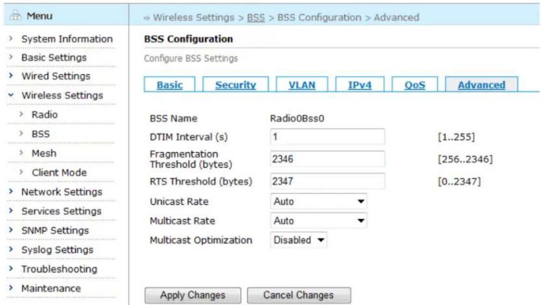
5.2.7. Configuring BSS Advanced Settings
Click the "Advanced" tab to enter the Advanced configuration page.
text_image
Menu System Information Basic Settings Wired Settings Wireless Settings Radio BSS Mesh Client Mode Network Settings Services Settings SNMP Settings Syslog Settings Troubleshooting Maintenance BSS Configuration Configure BSS Settings Basic Security VLAN IPv4 QoS Advanced BSS Name Radio0Bss0 DTIM Interval (s) 1 [1..255] Fragmentation 2346 [256..2346] Threshold (bytes) RTS Threshold (bytes) 2347 [0..2347] Unicast Rate Auto Multicast Rate Auto Multicast Optimization Disabled Apply Changes Cancel ChangesFigure 5-19 BSS Advanced Configuration Screen
Table below describes the Advanced settings for BSS interface.
Table 5-10 BSS Advanced Configuration Fields
| Setting | Explanation | Default |
| BSS Name | Display the BSS's Radio interface and BSS ID. Each radio supports up to 16 BSS | N/A |
| DTIM Interval | DTIM stands for Delivery Traffic Indication Message. It carries the DTIM interval. At DTIM interval, AP sends out buffered multicast and broadcast frames to clients in power-saving mode. The value range is 1-255. The default DTIM interval is 1, i.e., one beacon interval. That is, AP sends out buffered multicast and broadcast frames to power-saving clients every one beacon. | 1 |
| Fragmentation Threshold | Configure the threshold value (256-2346) for frame fragmentation. When the length of a frame exceeds the threshold value, the frame will be fragmented before being sent,2346: disable fragmentation | 2346 |
| RTS Threshold | Configure the threshold value (0-2347) for sending RTS frame. When the length of a frame exceeds the threshold value, a RST frame will be sent before the frame being sent, asking for avoiding conflict.0: always enable RTS2347: disable RTS | 2347 |
| Unicast Rate | Configure the unicast rate of this BSS: auto/fixed rate. The BSS will attempt to only apply the specified rate between clients and the BSS. The setting also prevents clients that do not support the specified rate from associating with this BSS. | Auto |
| Multicast Rate | Configure the multicast rate of this BSS: auto/fixed rate. The BSS will attempt to only apply the specified rate between clients and the BSS. | Auto |
Aruba Mesh Router Web-based Configuration Guide
| Multicast Optimization | Configure multicast frames to reduce packet loss rate of the multicast packet between the AP and the Client | Disabled |
Saving configuration for BSS Advance Setting
To save the configuration after editing the above settings, click the "Apply Changes" button. To discard any changes and return to the previous page, click the "Cancel Changes" button.
5.2.8. Deleting a BSS
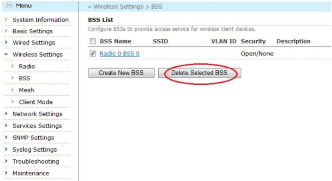
To delete existing BSSs, check the boxes beside each BSS to be deleted and click the "Delete Selected BSS" button.
text_image
Menu System Information Basic Settings Wired Settings Wireless Settings Radio BSS Mesh Client Mode Network Settings Services Settings SNMP Settings Syslog Settings Troubleshooting Maintenance BSS List Configure BSSs to provide access service for wireless client devices. BSS Name SSID VLAN ID Security Description Radio 0 BSS 0 Open/None Create New BSS Delete Selected BSSFigure 5-20 Deleting a BSS
5.3. Mesh Configuration
5.3.1. Configuring Mesh Basic
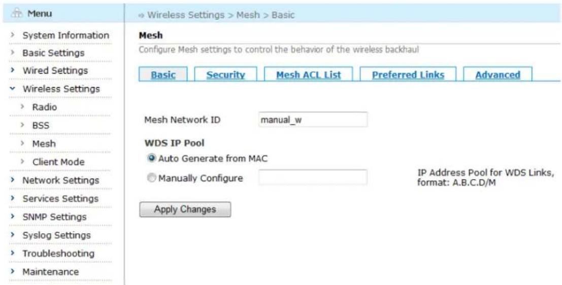
Click "Wireless Settings" > "Mesh" listed in the main menu tree. The resulting page shows the configuration and status of the mesh.
text_image
Menu System Information Basic Settings Wired Settings Wireless Settings Radio BSS Mesh Client Mode Network Settings Services Settings SNMP Settings Syslog Settings Troubleshooting Maintenance Mesh Configure Mesh settings to control the behavior of the wireless backhaul Basic Security Mesh ACL List Preferred Links Advanced Mesh Network ID manual_w WDS IP Pool Auto Generate from MAC Manually Configure Apply Changes IP Address Pool for WDS Links, format: A.B.C.D/MFigure 5-21 Mesh Basic Configuration Page
Table below describes the Mesh basic settings in this page.
Table 5-11 Mesh Basic Configuration Fields
| Setting | Explanation | Default |
| Mesh ID | Configure the Mesh ID | DefaultMesh |
| WDS IP Pool | Configure IP address pool for WDS links:1) Automatically generated from MAC2) Manually configure, format: A.B.C.D/M | Automatically generated from MAC |
Saving configuration for Mesh Basic
To save the configuration after editing the above settings, click the "Apply Changes" button.
5.3.2. Configuring Mesh Security
WDS supports 802.11 security standards. By clicking the "Security" tab in the Mesh Configuration page, enter the Authentication page. Choose Open/None, Open WEP, Shared WEP, WPA, WPA2 from the drop-down menu besides the "Security Type" to enter the security configuration page.

text_image
Menu System Information Basic Settings Wired Settings Ethernet Wireless Settings Radio BSS Mesh Client Mode Network Settings Services Settings SNMP Settings Syslog Settings Troubleshooting Maintenance Mesh Configure Mesh settings to control the behavior of the wireless backhaul Basic Security Mesh ACL List Preferred Links Advanced Security Type Open/None Open/None Open WEP Shared WEP WPA WPA2 Apply ChangesFigure 5-22 Mesh Security Configuration Screen
Open WEP
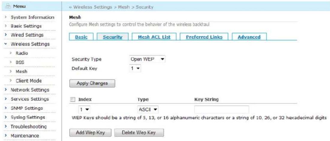
By clicking the drop down button beside the "Security Type" in the WDS Configuration page, choose Open WEP to enter the security configuration page.
text_image
Menu System Information Basic Settings Wired Settings Wireless Settings Radio BSS Mesh Client Mode Network Settings Services Settings SNMP Settings Syslog Settings Troubleshooting Maintenance Mesh Configure Mesh settings to control the behavior of the wireless backhaul Basic Security Mesh ACL List Preferred Links Advanced Security Type Open WEP Default Key 1 Apply Changes Index Type Key String 1 ASCII WEP Keys should be a string of 5, 13, or 16 alphanumeric characters or a string of 10, 26, or 32 hexadecimal digits Add Wep Key Delete Wep KeyFigure 5-23 Open WEP Configuration Page
In Open WEP encryption mode, the user can configure up to 4 keys and specify one of them as default key.
Shared WEP
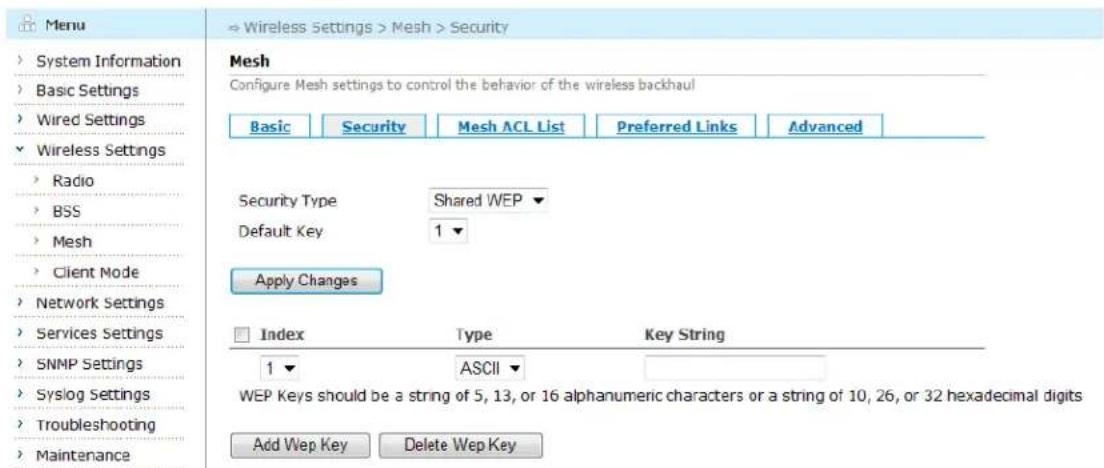
By clicking the drop down button beside the "Security Type" in the WDS Configuration page, choose Shared WEP to enter the security configuration page.
Aruba Mesh Router Web-based Configuration Guide
text_image
Menu System Information Basic Settings Wired Settings Wireless Settings Radio BSS Mesh Client Mode Network Settings Services Settings SNMP Settings Syslog Settings Troubleshooting Maintenance Mesh Configure Mesh settings to control the behavior of the wireless backhaul Basic Security Mesh ACL List Preferred Links Advanced Security Type Shared WEP Default Key 1 ▼ Apply Changes Index Type Key String 1 ASCII ▼ WEP Keys should be a string of 5, 13, or 16 alphanumeric characters or a string of 10, 26, or 32 hexadecimal digits Add Wep Key Delete Wep KeyFigure 5-24 Shared WEP Configuration Page
In Shared WEP encryption mode, the user can configure up to 4 keys and specify one of them as default key.
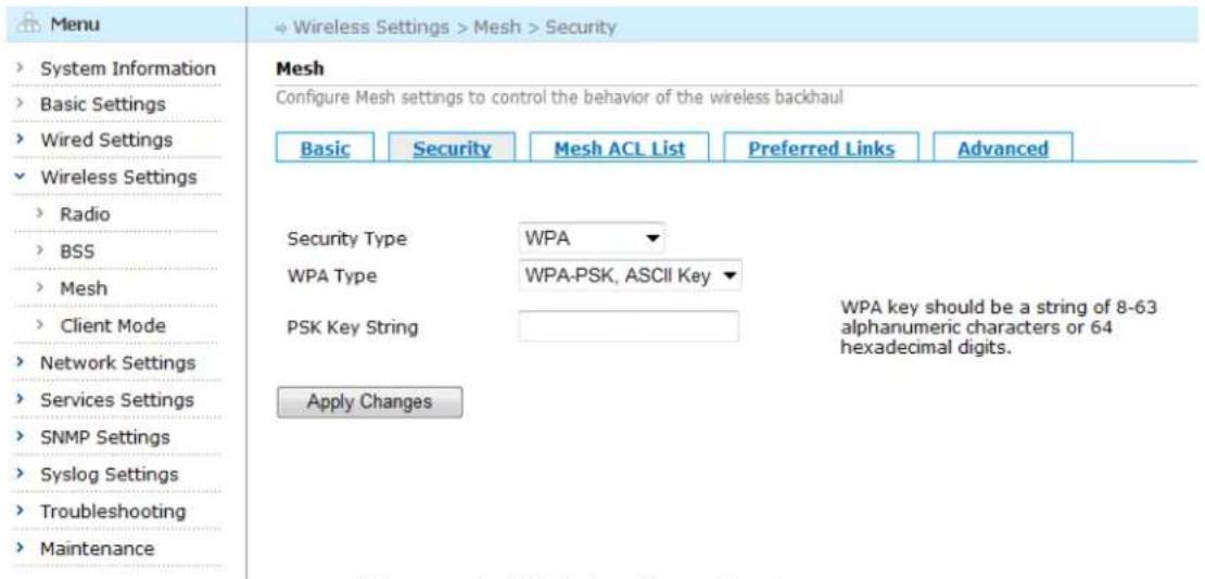
WPA
By clicking the drop down button beside the "Security Type" in the WDS Configuration page, choose WPA to enter the security configuration page.
text_image
Menu System Information Basic Settings Wired Settings Wireless Settings Radio BSS Mesh Client Mode Network Settings Services Settings SNMP Settings Syslog Settings Troubleshooting Maintenance Mesh Configure Mesh settings to control the behavior of the wireless backhaul Basic Security Mesh ACL List Preferred Links Advanced Security Type WPA WPA Type WPA-PSK, ASCII Key PSK Key String Apply Changes WPA key should be a string of 8-63 alphanumeric characters or 64 hexadecimal digits.Figure 5-25 WPA Configuration Page
Table below describes the WPA settings in this page.
Table 5-12 WPA Configuration Fields
| Setting | Explanation | Default |
| Authentication Type | Choose WPA | N/A |
| WPA Type | Choose WPA Type: | WPA-PSK, ASCII |
Aruba Mesh Router Web-based Configuration Guide
| 1) WPA-PSK, ASCII Key;2) WPA-PSK, Hex Key; | Key | |
| PSK Key String | ASCII code or hexadecimal key. The length of ASCII code is 8-63; the length of Hex is 64. | N/A |
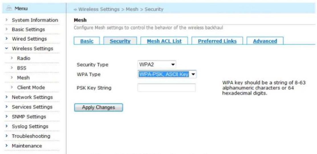
WPA2
By clicking the drop down button beside the "Security Type" in the WDS Configuration page, choose WPA2 to enter the security configuration page.
text_image
Menu System Information Basic Settings Wired Settings Wireless Settings Radio BSS Mesh Client Mode Network Settings Services Settings SNMP Settings Syslog Settings Troubleshooting Maintenance Mesh Configure Mesh settings to control the behavior of the wireless backhaul Basic Security Mesh ACL List Preferred Links Advanced Security Type WPA2 WPA Type WPA-PSK, ASCII Key PSK Key String WPA key should be a string of 8-63 alphanumeric characters or 64 hexadecimal digits. Apply ChangesFigure 5-26 WPA2 Configuration Page
Table below describes the WPA2 settings in this page.
Table 5-13 WPA Configuration Fields
| Setting | Explanation | Default |
| Authentication Type | Choose WPA2 | N/A |
| WPA Type | Choose WPA2 Type:1) WPA-PSK, ASCII Key;2) WPA-PSK, Hex Key; | WPA-PSK, ASCII Key |
| PSK Key String | ASCII code or hexadecimal key. The length of ASCII code is 8-63; the length of Hex is 64. | N/A |
Saving configuration for Mesh Security
To save the configuration after editing the above settings, click the "Apply Changes" button.
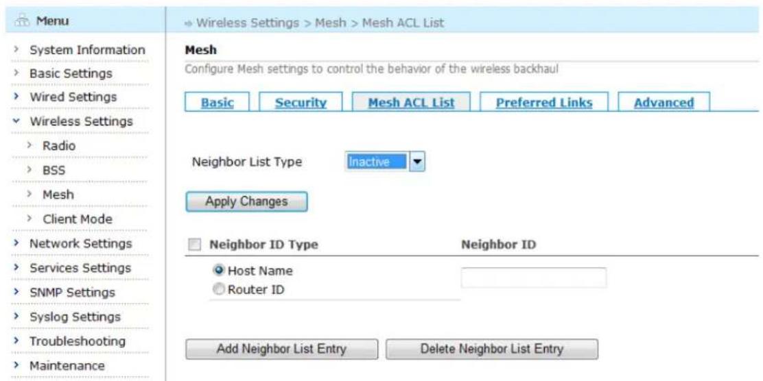
5.3.3. Configuring Mesh ACL List
Click the "Mesh ACL List" tab to enter the its configuration page.
text_image
Menu System Information Basic Settings Wired Settings Wireless Settings Radio BSS Mesh Client Mode Network Settings Services Settings SNMP Settings Syslog Settings Troubleshooting Maintenance Mesh Configure Mesh settings to control the behavior of the wireless backhaul Basic Security Mesh ACL List Preferred Links Advanced Neighbor List Type Inactive Apply Changes Neighbor ID Type Neighbor ID Host Name Router ID Add Neighbor List Entry Delete Neighbor List EntryFigure 5-27 Mesh ACL List Configuration Screen
Table below describes the Mesh ACL List settings for BSS interface.
Table 5-14 Mesh ACL List Configuration Fields
| Setting | Explanation | Default |
| Neighbor List Type | Choose neighbor list type, including:1) Inactive: don't care about the neighbor list when forming WDS links;2) White list: the neighbors defined in neighbor list are allowed to form WDS links3) Black list: the neighbors defined in neighbor list are not allowed to form WDS links | Inactive |
| Neighbor ID Type | Choose neighbor ID type, using neighbor hostname or router ID | Host Name |
| Neighbor ID | The neighbor's hostname or router-id | N/A |
Saving configuration for Mesh ACL List
To save the configuration after editing the above settings, click the "Apply Changes" button.
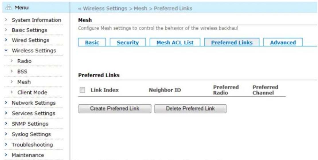
5.3.4. Configuring Preferred Links
Click the "Preferred Links" tab to enter its configuration page.
text_image
Menu System Information Basic Settings Wired Settings Wireless Settings Radio BSS Mesh Client Mode Network Settings Services Settings SNMP Settings Syslog Settings Troubleshooting Maintenance Mesh Configure Mesh settings to control the behavior of the wireless backhaul Basic Security Mesh ACL List Preferred Links Advanced Preferred Links Link Index Neighbor ID Preferred Radio Preferred Channel Create Preferred Link Delete Preferred LinkFigure 5-28 Preferred Links Configuration Screen
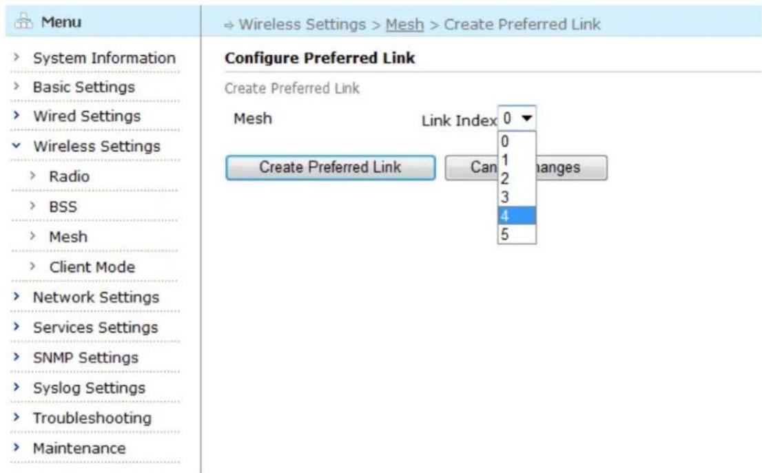
In the above configuration page, click "Create Preferred Link" button to enter the "Create Preferred Link" page.
text_image
Menu System Information Basic Settings Wired Settings Wireless Settings Radio BSS Mesh Client Mode Network Settings Services Settings SNMP Settings Syslog Settings Troubleshooting Maintenance Configure Preferred Link Create Preferred Link Mesh Link Index 0 ▼ 0 1 2 3 4 5 Create Preferred Link Can changesFigure 5-29 Create a Preferred Link
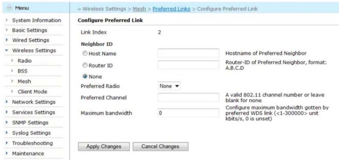
In this page, choose link index from the drop-down menu besides the Link Index. The "Configure Preferred Link" page appears.
text_image
Menu System Information Basic Settings Wired Settings Wireless Settings Radio BSS Mesh Client Mode Network Settings Services Settings SNMP Settings Syslog Settings Troubleshooting Maintenance Configure Preferred Link Link Index 2 Neighbor ID Host Name Router ID None Preferred Radio None ▼ Preferred Channel A valid 802.11 channel number or leave blank for none Maximum bandwidth 0 Configure maximum bandwidth gotten by preferred WDS link (<1-300000> unit kbits/s, 0 is unset) Apply Changes Cancel ChangesFigure 5-30 Configure Preferred Links Page
Table below describes the Preferred Links settings.
Table 5-15 Preferred Links Configuration Fields
| Setting | Explanation | Default |
| Neighbor ID | Configure Neighbor ID, using hostname or router ID. | None |
| Preferred Radio | Choose the radio to form connection. For MSR4000, you can choose 0-3; for MSR2000/MSR1200, you can choose 0-1 | None |
| Preferred Channel | Choose preferred channel | N/A |
| Maximum Bandwidth | Configure maximum bandwidth gotten by preferred WDS link. 0 is unset. | 0 |
Saving configuration for Preferred Link
To save the configuration after editing the above settings, click the "Apply Changes" button. To discard any changes and return to the previous page, click the "Cancel Changes" button.
5.3.5. Configuring Mesh Advanced Settings
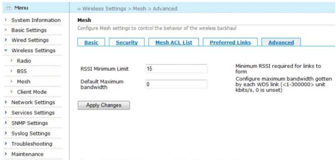
Click the "Advanced" tab to enter the Advanced configuration page.
text_image
Menu System Information Basic Settings Wired Settings Wireless Settings Radio BSS Mesh Client Mode Network Settings Services Settings SNMP Settings Syslog Settings Troubleshooting Maintenance Mesh Configure Mesh settings to control the behavior of the wireless backhaul Basic Security Mesh ACL List Preferred Links Advanced RSSI Minimum Limit 15 Minimum RSSI required for links to form Default Maximum bandwidth 0 Configure maximum bandwidth gotten by each WDS link (<1-300000> unit kbits/s, 0 is unset) Apply ChangesFigure 5-31 Mesh Advanced Configuration Screen
Table below describes the Advanced settings.
Table 5-16 Mesh Advanced Configuration Fields
| Setting | Explanation | Default |
| RSSIMinimum Limit | Minimum RSSI required for links to form | 15 |
| DefaultMaximum Bandwidth | Configure maximum bandwidth gotten by each WDS link. 0 is unset. | 0 |
Saving configuration for Mesh Advanced Settings
To save the configuration after editing the above settings, click the "Apply Changes" button. To discard any changes and return to the previous page, click the "Cancel Changes" button.
5.4. Client Mode Connection Configuration
Click "Wireless Settings" > "Client Mode" listed in the main menu tree.

text_image
Menu System Information Basic Settings Wired Settings Wireless Settings Radio BSS Mesh Client Mode Network Settings Services Settings SNMP Settings Syslog Settings Troubleshooting Maintenance List of Client Connections (STAs) Each client connection (STA) contains the settings for connecting this device to an AP/BSS as a standard 802.11 client □ Sta Name AP's SSID AP's BSSID VLAN ID Security Description □ Radio1Sta0 0 Open/None Create Delete Attached Device Address List Add IP addresses of attached devices which can be reached in a pure layer-3 network or in a layer-2/VPLM network. □ Device IP (A.B.C.D/M) Add DeleteFigure 5-32 Client Mode Configuration Page
In this page, users could create a client connection (STA) as well as configure or delete an existing one.
5.4.1. Creating a New/Entering an Existing Client-mode Connection
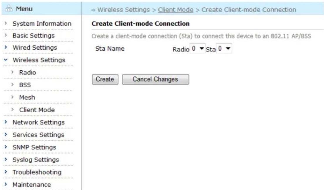
In this page, click "Create" button to enter the "Create Client-mode Connection" page.
text_image
Menu System Information Basic Settings Wired Settings Wireless Settings Radio BSS Mesh Client Mode Network Settings Services Settings SNMP Settings Syslog Settings Troubleshooting Maintenance Create Client-mode Connection Create a client-mode connection (Sta) to connect this device to an 802.11 AP/BSS Sta Name Radio 0 ▼ Sta 0 ▼ Create Cancel ChangesFigure 5-33 Creating Client-mode Connection
Select radio interface and station interface from the drop-down menu and click "Create" button to enter Client-mode Connection basic configuration page; click "Cancel Changes" button to discard any changes and return to the previous page.
Aruba Mesh Router Web-based Configuration Guide
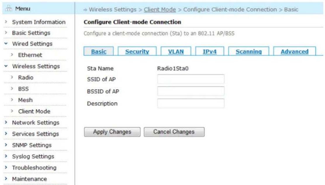
After clicking "Create" button, the basic configuration page for the new client-mode connection will appear, as shown in figure below:
text_image
Menu System Information Basic Settings Wired Settings Ethernet Wireless Settings Radio BSS Mesh Client Mode Network Settings Services Settings SNMP Settings Syslog Settings Troubleshooting Maintenance Configure Client-mode Connection Configure a client-mode connection (Sta) to an 802.11 AP/BSS Basic Security VLAN IPv4 Scanning Advanced Sta Name Radio1Sta0 SSID of AP BSSID of AP Description Apply Changes Cancel ChangesFigure 5-34 Basic Configuration Screen for a New Client-mode Connection
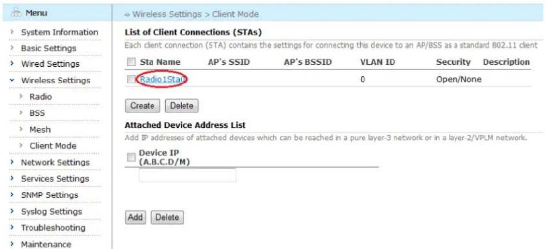
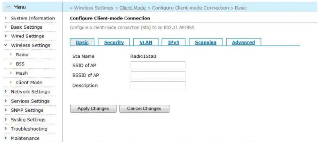
To enter an existing client-mode connection, click its Sta Name to enter the configuration page.
text_image
Menu System Information Basic Settings Wired Settings Wireless Settings Radio BSS Mesh Client Mode Network Settings Services Settings SNMP Settings Syslog Settings Troubleshooting Maintenance List of Client Connections (STAs) Each client connection (STA) contains the settings for connecting this device to an AP/BSS as a standard 802.11 client Sta Name AP's SSID AP's BSSID VLAN ID Security Description Radio1Sta0 0 Open/None Create Delete Attached Device Address List Add IP addresses of attached devices which can be reached in a pure layer-3 network or in a layer-2/VPLM network. Device IP (A.B.C.D/M) Add DeleteFigure 5-35 Entering an Existing Client-mode Connection Page
text_image
Menu System Information Basic Settings Wired Settings Wireless Settings Radio BSS Mesh Client Mode Network Settings Services Settings SNMP Settings Syslog Settings Troubleshooting Maintenance Configure Client-mode Connection Configure a client-mode connection (Sta) to an 802.11 AP/BSS Basic Security VLAN IPv4 Scanning Advanced Sta Name Radio1Sta0 SSID of AP BSSID of AP Description Apply Changes Cancel ChangesFigure 5-36 Basic Configuration Screen for an Existing Client-mode Connection
5.4.2. Configuring a Client-mode Connection (STA)
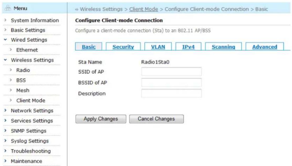
To configure a new created /an existing client-mode connection, enter the client-mode connection configuration page as stated above.
text_image
Menu System Information Basic Settings Wired Settings Ethernet Wireless Settings Radio BSS Mesh Client Mode Network Settings Services Settings SNMP Settings Syslog Settings Troubleshooting Maintenance Configure Client-mode Connection Configure a client-mode connection (Sta) to an 802.11 AP/BSS Basic Security VLAN IPv4 Scanning Advanced Sta Name Radio1Sta0 SSID of AP BSSID of AP Description Apply Changes Cancel ChangesFigure 5-37 Client-mode Connection Basic Configuration Screen
Table below describes the client-mode connection basic settings in this page.
Table 5-17 Client-mode Connection Basic Configuration Fields
| Setting | Explanation | Default |
| Sta Name | Display the station's radio interface and station interface. | N/A |
| SSID of AP | The 802.11 SSID for this AP | N/A |
| BSSID of AP | The 802.11 BSSID for this AP | N/A |
Aruba Mesh Router Web-based Configuration Guide
| Description | Describe the client-mode connection | N/A |
Saving Configuration for the Client-mode Connection
To save the configuration after editing the above settings, click the "Apply Changes" button. To discard any changes and return to the previous page, click the "Cancel Changes" button.
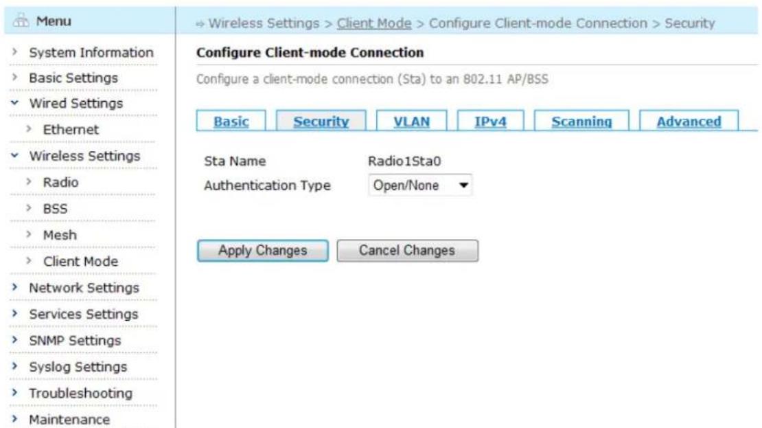
5.4.3. Configuring Client-mode Connection Security
Client-mode connection supports 802.11 security standards. By clicking the "Security" tab in the Configure Client-mode Connection page, enter the Security page. Choose Open WEP, Shared WEP, WPA, WPA2 from the drop-down menu besides the "Authentication Type" to enter the security configuration page.
Note: if choose Open/None from the drop-down menu besides "Authentication Type", no security configuration page appears.
text_image
Menu System Information Basic Settings Wired Settings Ethernet Wireless Settings Radio BSS Mesh Client Mode Network Settings Services Settings SNMP Settings Syslog Settings Troubleshooting Maintenance Configure Client-mode Connection Configure a client-mode connection (Sta) to an 802.11 AP/BSS Basic Security VLAN IPv4 Scanning Advanced Sta Name Radio1Sta0 Authentication Type Open/None ▼ Apply Changes Cancel ChangesFigure 5-38 Client-mode Connection Authentication Configuration Screen
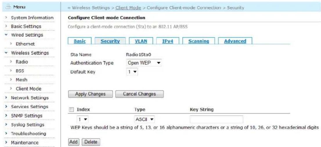
Open WEP
By clicking the drop down button beside the "Authentication Type" in the page, choose Open WEP to enter the security configuration page.
text_image
Menu ► System Information ► Basic Settings ► Wired Settings ► Ethernet ► Wireless Settings ► Radio ► BSS ► Mesh ► Client Mode ► Network Settings ► Services Settings ► SNMP Settings ► Syslog Settings ► Troubleshooting ► Maintenance ► Wireless Settings > Client Mode > Configure Client-mode Connection > Security Configure Client-mode Connection Configure a client-mode connection (Sta) to an 802.11 AP/BSS Basic Security VLAN IPv4 Scanning Advanced Sta Name Radio1Sta0 Authentication Type Open WEP Default Key 1 ▼ Apply Changes Cancel Changes Index Type Key String 1 ASCII WEP Keys should be a string of 5, 13, or 16 alphanumeric characters or a string of 10, 26, or 32 hexadecimal digits Add DeleteFigure 5-39 Client-mode Connection Open WEP Configuration Page
In Open WEP encryption mode, the user can configure up to 4 keys and specify one of them as default key.
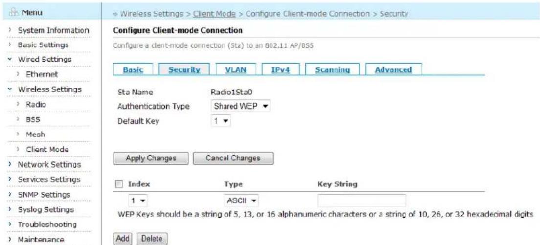
Shared WEP
By clicking the drop down button beside the "Authentication Type" in the page, choose Shared WEP to enter the security configuration page.
text_image
Menu System Information Basic Settings Wired Settings Ethernet Wireless Settings Radio BSS Mesh Client Mode Network Settings Services Settings SNMP Settings Syslog Settings Troubleshooting Maintenance Configure Client-mode Connection Configure a client-mode connection (Sta) to an 802.11 AP/BSS Basic Security VLAN IPv4 Scanning Advanced Sta Name Radio1Sta0 Authentication Type Shared WEP Default Key 1 Apply Changes Cancel Changes Index Type Key String 1 ASCII WEP Keys should be a string of 5, 13, or 16 alphanumeric characters or a string of 10, 26, or 32 hexadecimal digits Add DeleteFigure 5-40 Client-mode Connection Shared WEP Configuration Page
In Shared WEP encryption mode, the user can configure up to 4 keys and specify one of them as default key.
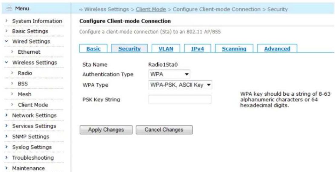
WPA
By clicking the drop down button beside the "Authentication Type" in the page, choose WPA to enter the security configuration page.
Aruba Mesh Router Web-based Configuration Guide
text_image
Menu System Information Basic Settings Wired Settings Ethernet Wireless Settings Radio BSS Mesh Client Mode Network Settings Services Settings SNMP Settings Syslog Settings Troubleshooting Maintenance Configure Client-mode Connection Configure a client-mode connection (Sta) to an 802.11 AP/BSS Basic Security VLAN IPv4 Scanning Advanced Sta Name Radio1Sta0 Authentication Type WPA WPA Type WPA-PSK, ASCII Key PSK Key String WPA key should be a string of 8-63 alphanumeric characters or 64 hexadecimal digits. Apply Changes Cancel ChangesFigure 5-41 Client-mode Connection WPA Configuration Page
Table below describes the WPA settings in this page.
Table 5-18 Client-mode Connection WPA Configuration Fields
| Setting | Explanation | Default |
| Sts Name | Display the station's radio interface and station interface. | N/A |
| Authentication Type | Choose WPA | N/A |
| WPA Type | Choose WPA Type:1) WPA-PSK, ASCII Key;2) WPA-PSK, Hex Key; | WPA-PSK, ASCII Key |
| PSK Key String | ASCII code or hexadecimal key. The length of ASCII code is 8-63; the length of Hex is 64. | N/A |
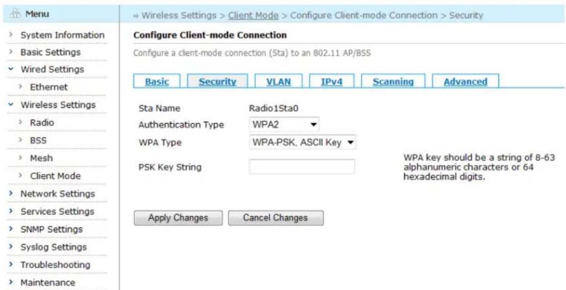
WPA2
By clicking the drop down button beside the "Authentication Type" in the page, choose WPA2 to enter the security configuration page.
text_image
Menu System Information Basic Settings Wired Settings Ethernet Wireless Settings Radio BSS Mesh Client Mode Network Settings Services Settings SNMP Settings Syslog Settings Troubleshooting Maintenance Configure Client-mode Connection Configure a client-mode connection (Sta) to an 802.11 AP/BSS Basic Security VLAN IPv4 Scanning Advanced Sta Name Radio1Sta0 Authentication Type WPA2 WPA Type WPA-PSK, ASCII Key PSK Key String WPA key should be a string of 8-63 alphanumeric characters or 64 hexadecimal digits. Apply Changes Cancel ChangesFigure 5-42 Client-mode Connection WPA2 Configuration Page
Table below describes the WPA2 settings in this page.
Table 5-19 Client-mode Connection WPA Configuration Fields
| Setting | Explanation | Default |
| Sts Name | Display the station's radio interface and station interface. | N/A |
| Authentication Type | Choose WPA2 | N/A |
| WPA Type | Choose WPA2 Type:1) WPA-PSK, ASCII Key;2) WPA-PSK, Hex Key; | WPA-PSK, ASCII Key |
| PSK Key String | ASCII code or hexadecimal key. The length of ASCII code is 8-63; the length of Hex is 64. | N/A |
Saving configuration for Client-mode Connection Security
To save the configuration after editing the above settings, click the "Apply Changes" button. To discard any changes and return to the previous page, click the "Cancel Changes" button.
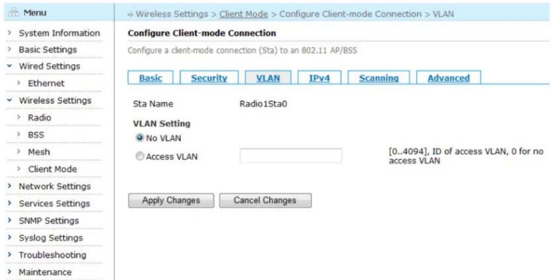
5.4.4. Configuring Client-mode Connection VLAN
Click the "VLAN" tab to enter the VLAN configuration page.
text_image
Menu System Information Basic Settings Wired Settings Ethernet Wireless Settings Radio BSS Mesh Client Mode Network Settings Services Settings SNMP Settings Syslog Settings Troubleshooting Maintenance Configure Client-mode Connection Configure a client-mode connection (Sta) to an 802.11 AP/BSS Basic Security VLAN IPv4 Scanning Advanced Sta Name Radio1Sta0 VLAN Setting No VLAN Access VLAN [0..4094], ID of access VLAN, 0 for no access VLAN Apply Changes Cancel ChangesFigure 5-43 Client-mode Connection VLAN Configuration Screen
Table below describes the VLAN settings for client-mode connection.
Table 5-20 Client-mode Connection VLAN Configuration Fields
| Setting | Explanation | Default |
| Sts Name | Display the station’s radio interface and station interface. | N/A |
| VLAN Setting | No VLAN: the client-mode connection doesn’t belong to any VLAN;Access VLAN: the client-mode connection belongs to a VLAN.The value range is 0-4094, 0 for no access VLAN. | No VLAN |
Saving Configuration for Client-mode Connection VLAN
To save the configuration after editing the above settings, click the "Apply Changes" button. To discard any changes and return to the previous page, click the "Cancel Changes" button.
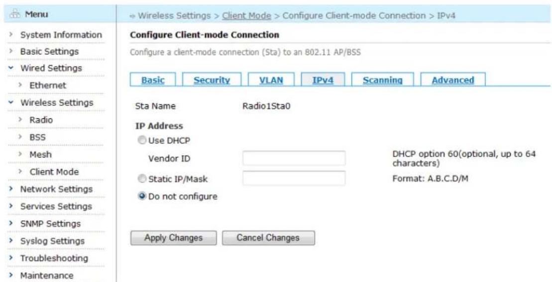
5.4.5. Configuring Client-mode Connection IPv4
Click the "IPv4" tab to enter the IPv4 configuration page.
text_image
Menu System Information Basic Settings Wired Settings Ethernet Wireless Settings Radio BSS Mesh Client Mode Network Settings Services Settings SNMP Settings Syslog Settings Troubleshooting Maintenance Configure Client-mode Connection Configure a client-mode connection (Sta) to an 802.11 AP/BSS Basic Security VLAN IPv4 Scanning Advanced Sta Name Radio1Sta0 IP Address Use DHCP Vendor ID DHCP option 60(optional, up to 64 characters) Static IP/Mask Format: A.B.C.D/M Do not configure Apply Changes Cancel ChangesFigure 5-44 Client-mode Connection IPv4 Configuration Screen
Table below describes the IPv4 settings for client-mode connection.
Table 5-21 Client-mode Connection IPv4 Configuration Fields
| Setting | Explanation | Default |
| Sts Name | Display the station's radio interface and station interface. | N/A |
| IP Address | Configure the IPv4 address for this client-mode connection:1) Use DHCP: Enter vendor ID, configure DHCP Option 60 (up to 64 characters)2) Static IP address/Mask, format: A.B.C.D/M3) Do not configure | Do not configure |
Saving configuration for Client-mode Connection IPv4
To save the configuration after editing the above settings, click the "Apply Changes" button. To discard any changes and return to the previous page, click the "Cancel Changes" button.
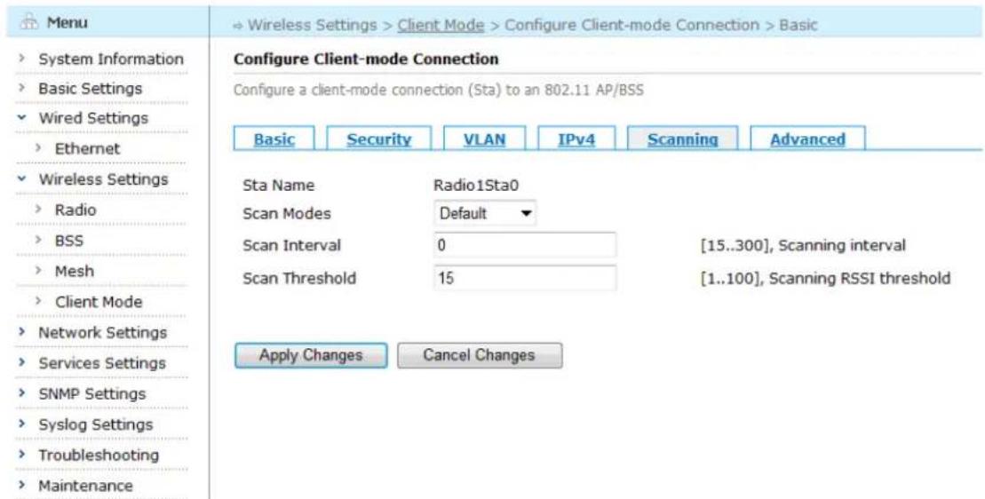
5.4.6. Configuring Client-mode Connection Scanning
Click the "Scanning" tab to enter the Scanning configuration page.
text_image
Menu System Information Basic Settings Wired Settings Ethernet Wireless Settings Radio BSS Mesh Client Mode Network Settings Services Settings SNMP Settings Syslog Settings Troubleshooting Maintenance Configure Client-mode Connection Configure a client-mode connection (Sta) to an 802.11 AP/BSS Basic Security VLAN IPv4 Scanning Advanced Sta Name Radio1Sta0 Scan Modes Default Scan Interval 0 [15..300], Scanning interval Scan Threshold 15 [1..100], Scanning RSSI threshold Apply Changes Cancel ChangesFigure 5-45 Client-mode Connection Scanning Configuration Screen
Table below describes the scanning settings for client-mode connection.
Table 5-22 Client-mode Connection Scanning Configuration Fields
| Setting | Explanation | Default |
| Sts Name | Display the station's radio interface and station interface. | N/A |
| Scan Modes | Configure the scan modes | Default |
| Scan Interval | Configure the seconds between each scan (15-300 seconds)0 means unset | 0 |
| Scan Threshold | Configure the threshold value for scanning | 15 |
Saving configuration for Client-mode Connection Scanning
To save the configuration after editing the above settings, click the "Apply Changes" button. To discard any changes and return to the previous page, click the "Cancel Changes" button.
5.4.7. Configuring Client-mode Connection Advanced Settings
Click the "Advanced" tab to enter the Advanced configuration page.
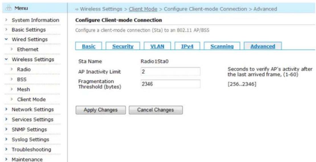
text_image
Menu System Information Basic Settings Wired Settings Ethernet Wireless Settings Radio BSS Mesh Client Mode Network Settings Services Settings SNMP Settings Syslog Settings Troubleshooting Maintenance Configure Client-mode Connection Configure a client-mode connection (Sta) to an 802.11 AP/BSS Basic Security VLAN IPv4 Scanning Advanced Sta Name Radio1Sta0 AP Inactivity Limit 2 Seconds to verify AP's activity after the last arrived frame, (1-60) Fragmentation 2346 [256..2346] Threshold (bytes) Apply Changes Cancel ChangesFigure 5-46 Client-mode Connection Advanced Configuration Screen
Table below describes the Advanced settings for client-mode connection.
Table 5-23 Client-mode Connection Advanced Configuration Fields
| Setting | Explanation | Default |
| Sts Name | Display the station's radio interface and station interface. | N/A |
| AP Inactivity Limit | Configure the maximum amount of time (1-60 seconds) an AP is allowed to be inactive before the inactivity policy takes effect. | 2 |
| Fragmentation Threshold | Configure the threshold value (256-2346) for frame fragmentation. When the length of a frame exceeds the threshold value, the frame will be fragmented before being sent,2346: disable fragmentation | 2346 |
Saving configuration for Client-mode Connection Advance Setting
To save the configuration after editing the above settings, click the "Apply Changes" button. To discard any changes and return to the previous page, click the "Cancel Changes" button.
Chapter 6 Network Settings
This chapter contains the following content:
- Configuring Routing
- DHCP Configuration
• VLAN Configuration - Loopback Configuration
- NTP Configuration
6.1. Configuring Routing
The Routing Table is the information database used by routers to track the topology of the network and to determine how each data packet would be forwarded. This chapter describes how routing tables may be viewed using the wireless mesh router's Web-based Management Interface and how static routes, OSPF routes, AWR routes and Multicast may be configured.
6.1.1. Routing Table Configuration
In the menu tree, select "Network Settings" > "Routing" > "Static Routes" to bring up the Static Routes configuration page.
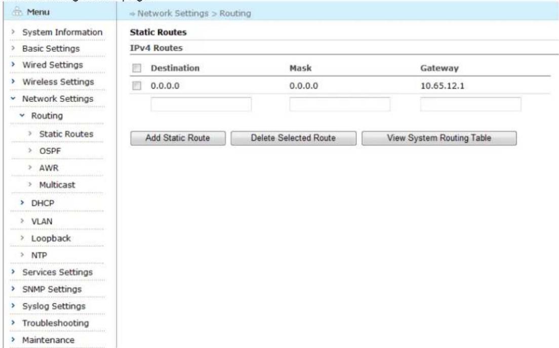
text_image
Menu System Information Basic Settings Wired Settings Wireless Settings Network Settings Routing Static Routes IPv4 Routes Destination Mask Gateway 0.0.0.0 0.0.0.0 10.65.12.1 Add Static Route Delete Selected Route View System Routing TableFigure 6-1 Static Routes Page
Table below explains the various fields in the static routes page.
Table 6-1 Static Routes Page Fields
| Column | Explanation |
| Destination | The destination network or host address. |
| Mask | The mask indicating the prefix for the destination; the destination and mask are used together to determine whether a packet's destination address matches a particular route. |
| Gateway | The gateway IP address that this device points to. If an IP address is shown, then packets would be forwarded to this address. If an interface is shown, then packets would be forwarded using this interface. |
6.1.2. Adding an IPv4 Static Route
To add a new IPv4 Static Route, enter destination, mask and gateway in the boxes indicated in the red circle, and click the "Add Static Route" button.
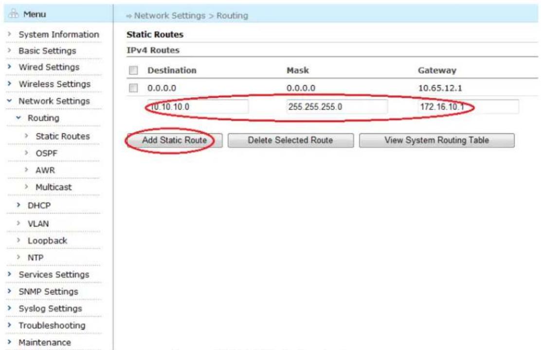
text_image
Menu System Information Basic Settings Wired Settings Wireless Settings Network Settings Routing Static Routes IPv4 Routes Destination Mask Gateway 0.0.0.0 0.0.0.0 10.65.12.1 10.10.10.0 255.255.255.0 172.16.10.1 Add Static Route Delete Selected Route View System Routing TableFigure 6-2 Add Static Route Page
Table below describes the settings for an IPv4 static route entry.
Table 6-2 Static Route Entry Fields
| Setting | Explanation | Default |
| Destination | The destination network or host address for this route.This field is required; when creating a default route, use 0.0.0.0 | N/A |
| Mask | The mask indicating the prefix for the destination; the destination and mask are used together to determine whether a packet's destination address matches a particular route | N/A |
Aruba Mesh Router Web-based Configuration Guide
| This field is required; when creating a default route, use 0.0.0.0 | ||
| Gateway | The gateway IP address that this route points to. | N/A |
The figure below shows the resulting page when the new IPv4 static route is successfully added.
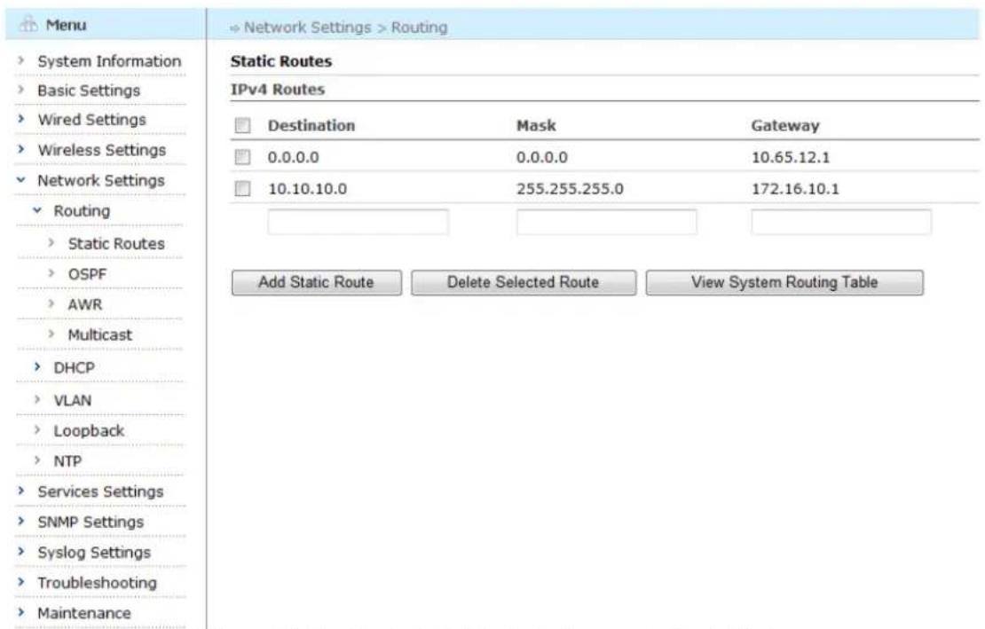
text_image
Menu System Information Basic Settings Wired Settings Wireless Settings Network Settings Routing Static Routes OSPF AWR Multicast DHCP VLAN Loopback NTP Services Settings SNMP Settings Syslog Settings Troubleshooting Maintenance Static Routes IPv4 Routes Destination Mask Gateway 0.0.0.0 0.0.0.0 10.65.12.1 10.10.10.0 255.255.255.0 172.16.10.1 Add Static Route Delete Selected Route View System Routing TableFigure 6-3 An IPv4 Static Route is Successfully Added
6.1.3. Deleting an IPv4 Static Route
To delete an existing IPv4 static route, check the boxes beside the routes to be deleted and click the "Delete Static Route" button.
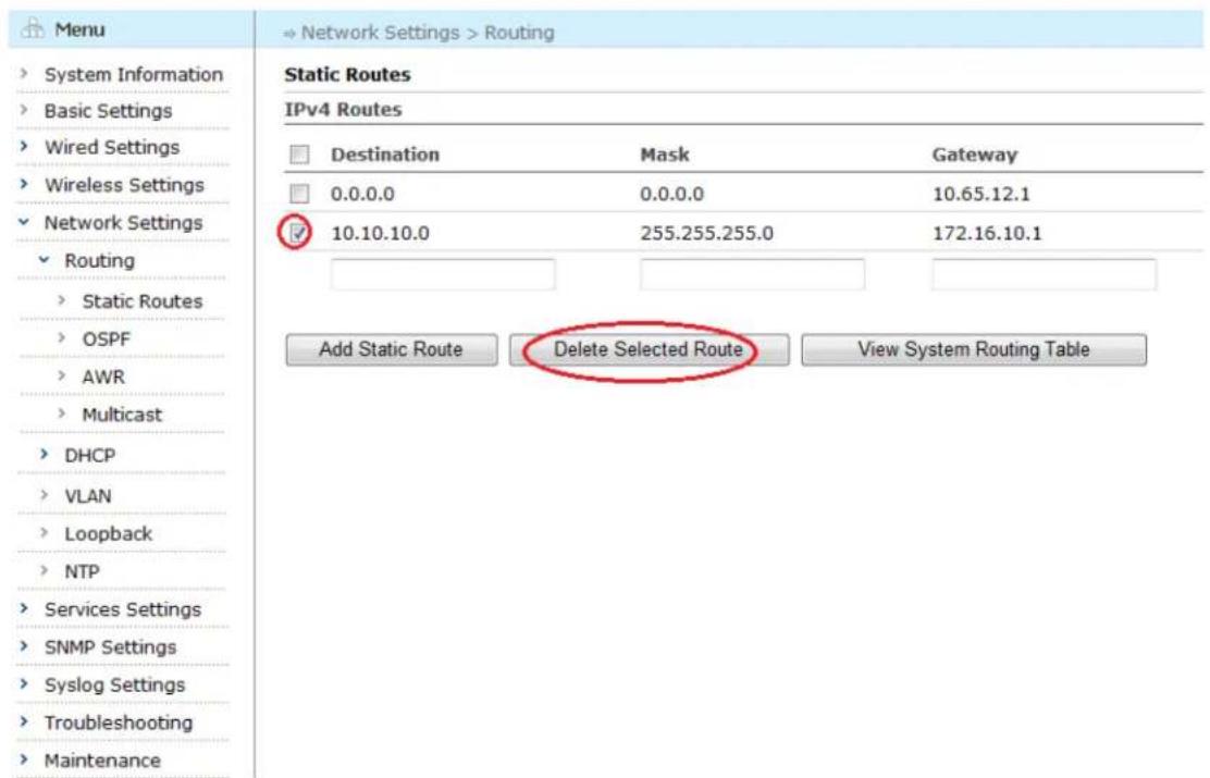
text_image
Menu System Information Basic Settings Wired Settings Wireless Settings Network Settings Routing Static Routes IPv4 Routes Destination Mask Gateway 0.0.0.0 0.0.0.0 10.65.12.1 ✓ 10.10.10.0 255.255.255.0 172.16.10.1 Add Static Route Delete Selected Route View System Routing TableFigure 6-4 Delete IPv4 Static Route Page
6.1.4. View IPv4 System Routing Table
To view the IPv4 system routing table, enter destination, click the "View System Routing Table" button.
| Menu | » Network Settings > Routing > Routing Table | ||||
| System Information | Routing Table | ||||
| Basic Settings | View System Routing Table | ||||
| Wired Settings | Codes: K - kernel route, C - connected, S - static, d - DHCP, > - selected route, * - FIB route | ||||
| Wireless Settings | IPv4 | ||||
| Network Settings | Destination | Mask | Gateway/Interface | Hop Count | Type |
| Routing | 0.0.0.0 | 0.0.0.0 | 10.65.12.1/gigabit- ethernet 0 | 1/0 | S>* |
| Static Routes | 10.44.81.209 | 255.255.255.255 | loopback 0 | Directly | C>* |
| OSPF | 10.65.12.0 | 255.255.255.0 | gigabit-ethernet 0 | Directly | C>* |
| AWR | |||||
| Multicast | |||||
| DHCP | |||||
| VLAN | |||||
| Loopback | |||||
| NTP | |||||
| Services Settings | |||||
| SNMP Settings | |||||
| Syslog Settings | |||||
| Troubleshooting | |||||
| Maintenance | |||||
Figure 6-5 IPv4 System Routing Table Page
Table below explains the various fields in the system routing table page.
Table 6-3 System Routing Table Fields
| Column | Explanation |
| Destination | The destination network or host address. |
| Mask | The mask indicating the prefix for the destination; the destination and mask are used together to determine whether a packet's destination address matches a particular route. |
| Gateway/interface | The gateway IP address that this device points to. If an IP address is shown, then packets would be forwarded to this address. If an interface is shown, then packets would be forwarded using this interface. |
| Hop Count | The number of hops between the device and the destination network. However, the following special values may apply:Directly: Indicates directly connected route of the device. |
| Type | A three-character code that indicates the type of the route.First character: K indicates a kernel route, C indicates a directly-connected route, S indicates a static route, H indicates a host route, O indicate a OSPF route, A indicate a AWR route, d indicate a direct route obtained by DHCP.Second character: ‘>’ indicates the selected route when there are other routes with the same destination and mask.Third character: ‘*’ indicates that the route is active in the router kernel. |
6.1.5. OSPF Configuration Page
Select "Network Settings" > "Routing" > "OSPF" from the left menu tree to open the OSPF configuration page. The OSPF Configuration Page appears.
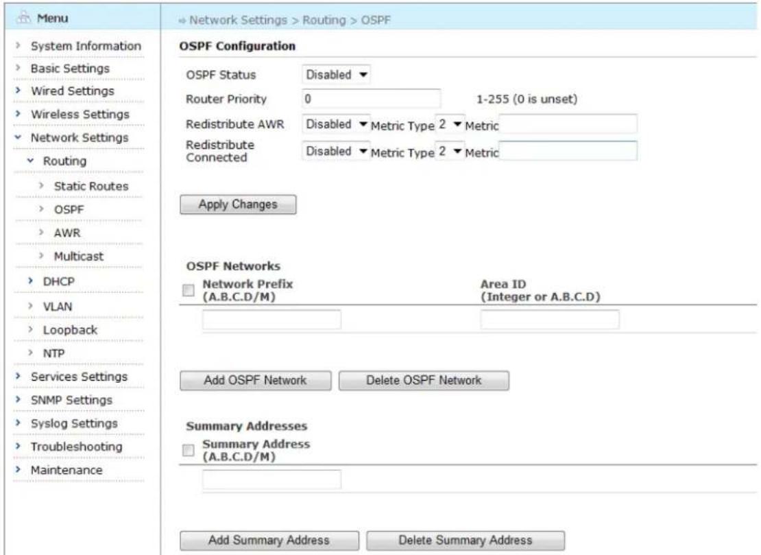
text_image
Menu System Information Basic Settings Wired Settings Wireless Settings Network Settings Routing Static Routes OSPF AWR Multicast DHCP VLAN Loopback NTP Services Settings SNMP Settings Syslog Settings Troubleshooting Maintenance OSPF Configuration OSPF Status Disabled ▼ Router Priority 0 1-255 (0 is unset) Redistribute AWR Disabled ▼ Metric Type 2 ▼ Metric Redistribute Connected Disabled ▼ Metric Type 2 ▼ Metric Apply Changes OSPF Networks Network Prefix Area ID (A.B.C.D/M) (Integer or A.B.C.D) Add OSPF Network Delete OSPF Network Summary Addresses Summary Address (A.B.C.D/M) Add Summary Address Delete Summary AddressFigure 6-6 OSPF Configuration Page
Table below describes the OSPF settings in this page.
Table 6-4 OSPF Configuration Fields
| Setting | Explanation | Default |
| OSPF Status | OSPF is enabled or disabled | Disabled |
| Router Priority | The OSPF priority, and its value range is 1-255. When the priority is 0, the router can't become DR. | 0 |
| Redistribute AWR | Redistribute AWR to OSPF field and define meric type (1-2) and metric value | Disabled |
| Redistribute Direct Connected Route | Redistribute Direct Connected Route to OSPF field and define meric type (1-2) and metric value | Disabled |
| Metric Type | Define meric type (1-2) | 2 |
| Network Prefix | Configure the network segment that runs OSPF route. The format is A.B.C.D/M | N/A |
| OSPF Area ID | Integer or A.B.C.D. Currently only support one OSPF Area ID | N/A |
| Summary Address | OSPF supports route aggregation function, summarizing the specified network segment. The format is A.B.C.D/M | N/A |
Aruba Mesh Router Web-based Configuration Guide
Saving configuration for OSPF
To save the configuration after editing the above settings, click the "Apply Changes" button.
6.1.6. Adding OSPF Network
To add a new OSPF network, enter the network prefix and OSPF Area ID in the boxes indicated in the red circle and clicks the "Add OSPF Network" button.
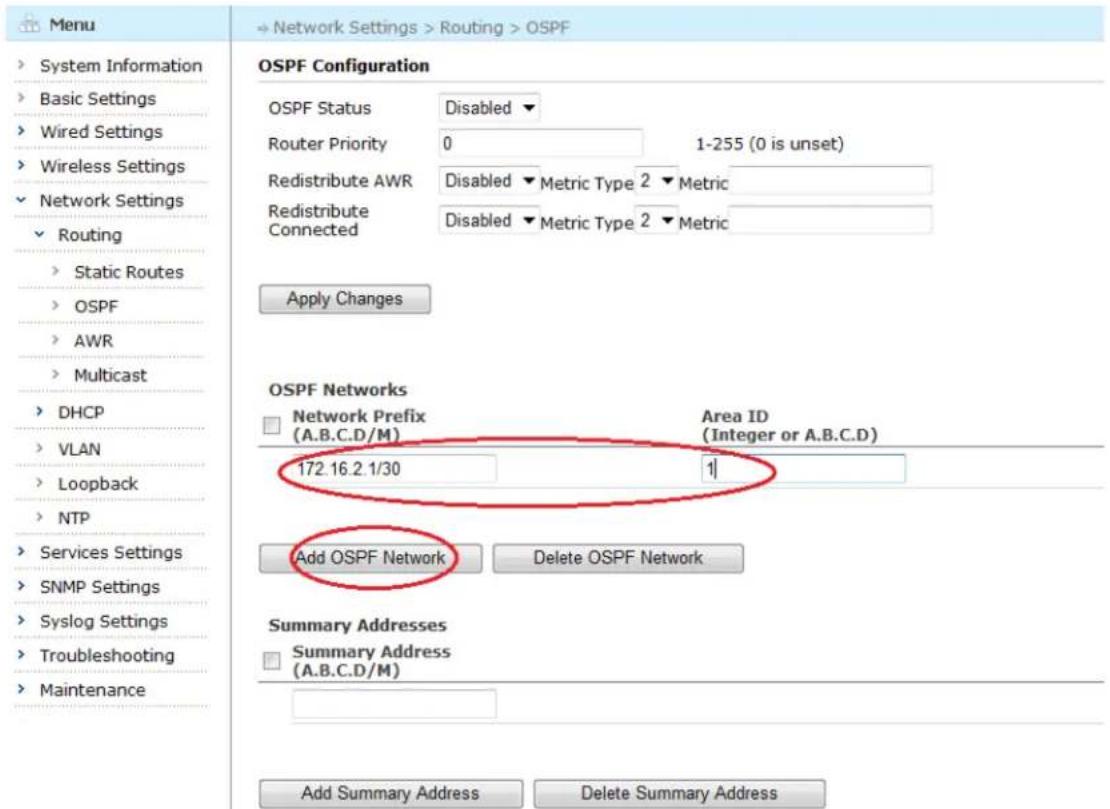
text_image
Menu System Information Basic Settings Wired Settings Wireless Settings Network Settings Routing Static Routes OSPF AWR Multicast DHCP VLAN Loopback NTP Services Settings SNMP Settings Syslog Settings Troubleshooting Maintenance Network Settings > Routing > OSPF OSPF Configuration OSPF Status Disabled ▼ Router Priority 0 1-255 (0 is unset) Redistribute AWR Disabled ▼ Metric Type 2 ▼ Metric Redistribute Connected Disabled ▼ Metric Type 2 ▼ Metric Apply Changes OSPF Networks □ Network Prefix Area ID (A.B.C.D/M) (Integer or A.B.C.D) Area ID (Integer or A.B.C.D) 172.16.2.1/30 1/ Add OSPF Network Delete OSPF Network Summary Addresses □ Summary Address (A.B.C.D/M) Add Summary Address Delete Summary AddressFigure 6-7 Adding New OSPF Network
6.1.7. Deleting OSPF Network
To delete an existing OSPF network, check the boxes beside the network to be deleted and click the "Delete OSPF Network" button.
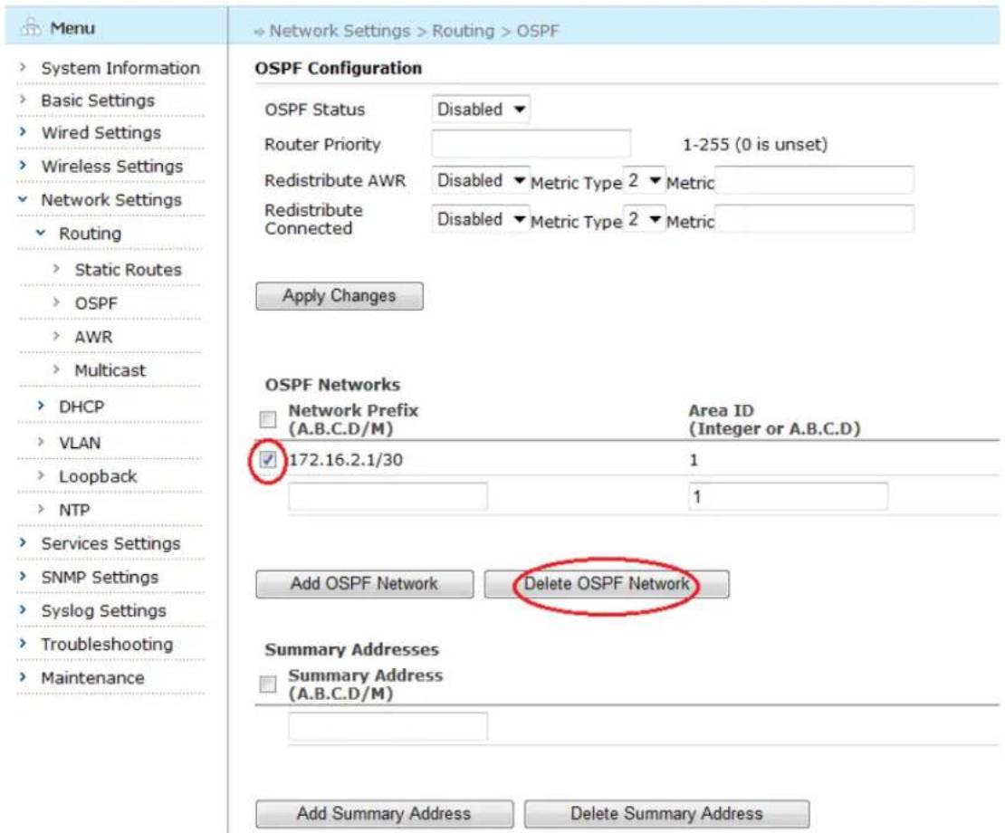
text_image
Menu System Information Basic Settings Wired Settings Wireless Settings Network Settings Routing Static Routes OSPF AWR Multicast DHCP VLAN Loopback NTP Services Settings SNMP Settings Syslog Settings Troubleshooting Maintenance OSPF Configuration OSPF Status Disabled ▼ Router Priority 1-255 (0 is unset) Redistribute AWR Disabled ▼ Metric Type 2 ▼ Metric Redistribute Connected Disabled ▼ Metric Type 2 ▼ Metric Apply Changes OSPF Networks Network Prefix Area ID (A.B.C.D/M) (Integer or A.B.C.D) 172.16.2.1/30 1 Add OSPF Network Delete OSPF Network Summary Addresses Summary Address (A.B.C.D/M) Add Summary Address Delete Summary AddressFigure 6-8 Deleting an Existing OSPF Network
6.1.8. Adding Summary Address
To add a new summary address, enter the summary address in the box and click the "Add Summary Address" button.
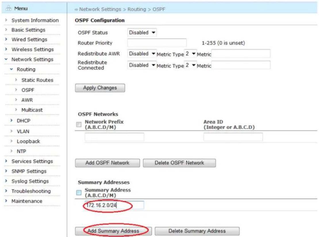
text_image
Menu System Information Basic Settings Wired Settings Wireless Settings Network Settings Routing Static Routes OSPF AWR Multicast DHCP VLAN Loopback NTP Services Settings SNMP Settings Syslog Settings Troubleshooting Maintenance OSPF Configuration OSPF Status Disabled ▼ Router Priority 1-255 (0 is unset) Redistribute AWR Disabled ▼ Metric Type 2 ▼ Metric Redistribute Connected Disabled ▼ Metric Type 2 ▼ Metric Apply Changes OSPF Networks Network Prefix Area ID (A.B.C.D/M) (Integer or A.B.C.D) Add OSPF Network Delete OSPF Network Summary Addresses Summary Address (A.B.C.D/M) 172.16.2.0/24 Add Summary Address Delete Summary AddressFigure 6-9 Adding Summary Address
6.1.9. Deleting Summary Address
To delete an existing summary address, check the boxes beside the summary address to be deleted and click the "Delete Summary Address" button.
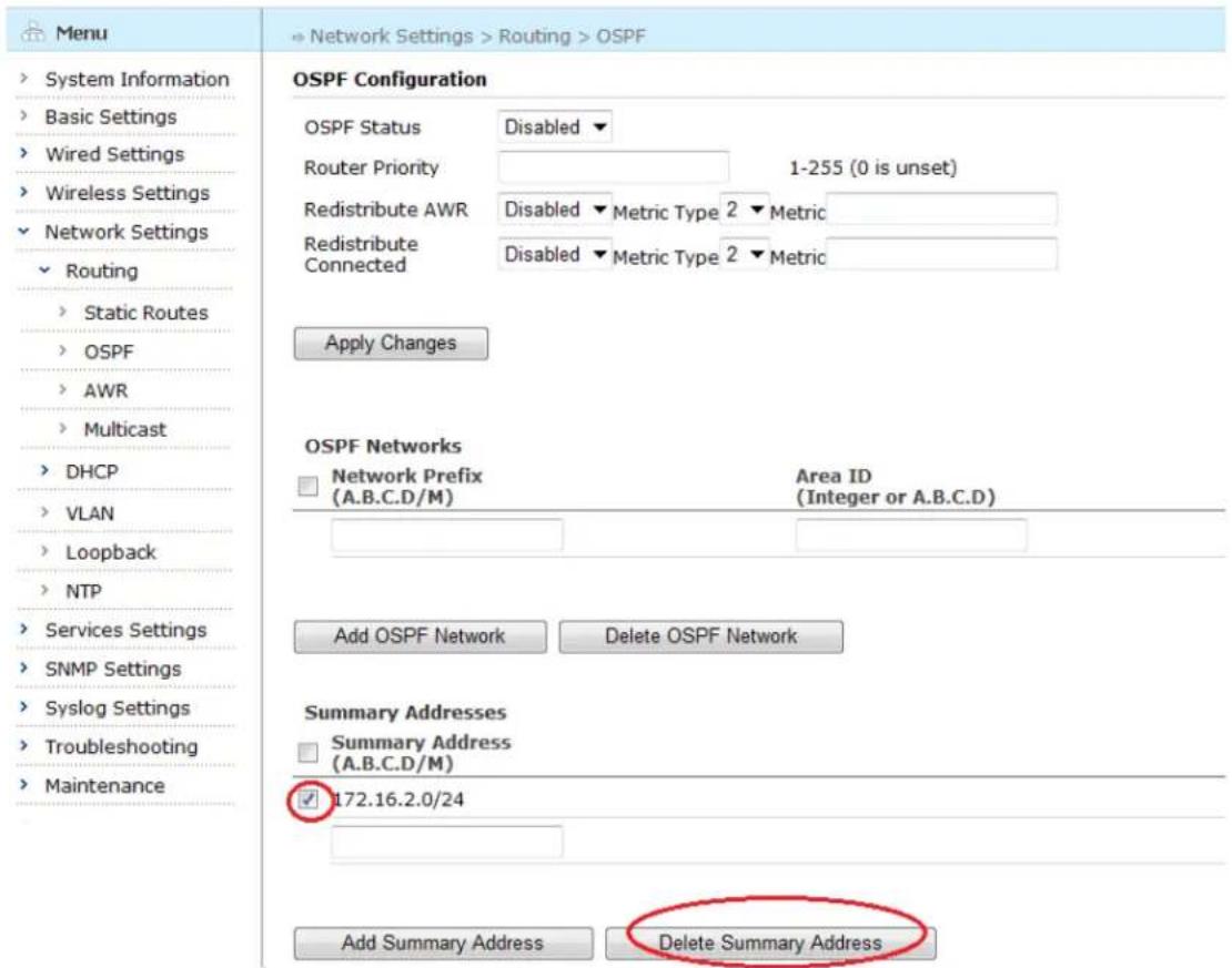
text_image
Menu System Information Basic Settings Wired Settings Wireless Settings Network Settings Routing Static Routes OSPF AWR Multicast DHCP VLAN Loopback NTP Services Settings SNMP Settings Syslog Settings Troubleshooting Maintenance OSPF Configuration OSPF Status Disabled ▼ Router Priority 1-255 (0 is unset) Redistribute AWR Disabled ▼ Metric Type 2 ▼ Metric Redistribute Connected Disabled ▼ Metric Type 2 ▼ Metric Apply Changes OSPF Networks Network Prefix Area ID (A.B.C.D/M) (Integer or A.B.C.D) Add OSPF Network Delete OSPF Network Summary Addresses Summary Address (A.B.C.D/M) 172.16.2.0/24 Add Summary Address Delete Summary AddressFigure 6-10 Deleting an Existing Summary Address
6.1.10. AWR Configuration Page
Select "Network Settings" > "Routing" > "AWR" from the left menu tree to open the AWR configuration page. The AWR Configuration Page appears.
| Menu | → Network Settings >Routing >AWR | |
| System Information | AWR Configuration | |
| Basic Settings | AWR Status | Enabled ▼ |
| Wired Settings | Debug Level | Error ▼ |
| Wireless Settings | Use Hello Protocol on Mesh Links | Disabled ▼ |
| Network Settings | Primary Gateway Election | Disabled ▼ |
| Routing | ||
| Static Routes | Apply Changes | |
| OSPF | ||
| AWR | ||
| Multicast | ||
| DHCP | ||
| VLAN | ||
| Loopback | ||
| NTP | ||
| Services Settings | ||
| SNMP Settings | ||
| Syslog Settings | ||
| Troubleshooting | ||
| Maintenance | ||
Figure 6-11 AWR Configuration Page
Table below describes the AWR Route settings in this page.
Table 6-5 AWR Route Configuration Fields
| Setting | Explanation | Default |
| AWR Status | AWR is enabled or disabled | Enabled |
| Debug Level | Configure the debug level for AWR, including None, Error, Event, Info, Dump | Error |
| Use Hello Protocol on Mesh Links | Enable or disable “Use Hello Protocol on Mesh Links” | Disabled |
| Primary Gateway Election | Enable or disable Primary Gateway Election | Disabled |
Saving configuration for AWR
To save the configuration after editing the above settings, click the "Apply Changes" button.
6.1.11. Multicast Configuration Page
Select "Network Settings" > "Routing" > "Multicast" from the left menu tree to open the Multicast configuration page. The Multicast Configuration Page appears.
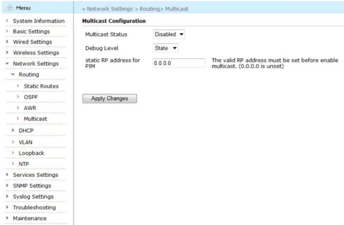
text_image
Menu System Information Basic Settings Wired Settings Wireless Settings Network Settings Routing Static Routes OSPF AWR Multicast DHCP VLAN Loopback NTP Services Settings SNMP Settings Syslog Settings Troubleshooting Maintenance Multicast Configuration Multicast Status Disabled ▼ Debug Level State ▼ static RP address for 0.0.0.0 The valid RP address must be set before enable multicast. (0.0.0.0 is unset) Apply ChangesFigure 6-12 Multicast Configuration Page
Table below describes the Multicast settings in this page.
Table 6-6 Multicast Configuration Fields
| Setting | Explanation | Default |
| Multicast Status | Multicast is enabled or disabled | Disabled |
| Debug Level | Configure the debug level for AWR, including None, Error, State, Info, Dump | State |
| Static RP Address for PIM | Configure the IP address of the RP (Rendezvous Point). Each router (including the RP router) enabling multicast should configure the RP address. 0.0.0.0 is unset. | 0.0.0.0 |
Saving configuration for Multicast
To save the configuration after editing the above settings, click the "Apply Changes" button.
6.2. Configuring DHCP
6.2.1. DHCP Server Configuration
Enter the DHCP Server configuration page by selecting "Network Settings" > "DHCP" > "DHCP Server" in the left-side menu tree.
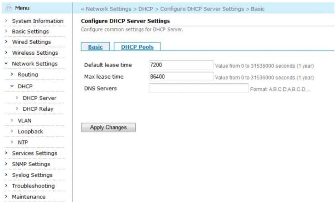
text_image
Menu System Information Basic Settings Wired Settings Wireless Settings Network Settings Routing DHCP DHCP Server DHCP Relay VLAN Loopback NTP Services Settings SNMP Settings Syslog Settings Troubleshooting Maintenance Configure DHCP Server Settings Configure common settings for DHCP Server. Basic DHCP Pools Default lease time 7200 Value from 0 to 31536000 seconds (1 year) Max lease time 86400 Value from 0 to 31536000 seconds (1 year) DNS Servers Format: A.B.C.D.A.B.C.D,... Apply ChangesFigure 6-13 DHCP Server Configuration Page
Table below describes the settings for DHCP Server.
Table 6-7 DHCP Server Settings
| Setting | Explanation | Default |
| Default lease time | The amount of time (in seconds) allowed for an IP address assignment (hereby referred to a lease) before it expires, if the client did not request for a specific lease length, it will be the default value. Value Range: 0-31536000s | 7200 |
| Max lease time | The maximum amount of time (in seconds) allowed for a lease regardless of the client's request Value Range: 0-31536000s | 86400 |
| DNS Addresses | A comma-separated list of DNS server addresses that would be given to clients along with the lease. Example: 206.56.44.1,206.56.33.1 | N/A |
Saving configuration for DHCP Basic
To save the configuration after editing the above settings, click the "Apply Changes" button.
6.2.2. Adding a New DHCP Pool
To add a new DHCP pool, click the "DHCP Pools" tab, and then click the "Add New Pool" button, the configuration page appears:
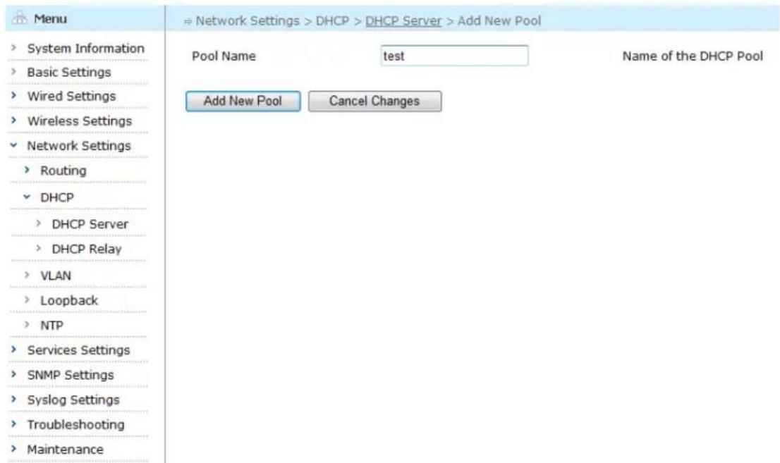
text_image
Menu System Information Basic Settings Wired Settings Wireless Settings Network Settings Routing DHCP DHCP Server DHCP Relay VLAN Loopback NTP Services Settings SNMP Settings Syslog Settings Troubleshooting Maintenance → Network Settings > DHCP > DHCP Server > Add New Pool Pool Name test Name of the DHCP Pool Add New Pool Cancel ChangesFigure 6-14 Add a New DHCP Pool
In this page, enter the Pool name you want to call the new DHCP pool, such as test, in the blank box.
6.2.3. Configuring the New DHCP Pool
To configure the new DHCP pool, click the "Add New Pool" button, the configuration page appears:

text_image
Menu System Information Basic Settings Wired Settings Wireless Settings Network Settings Routing DHCP DHCP Server DHCP Relay VLAN Loopback NTP Services Settings SNMP Settings Syslog Settings Troubleshooting Maintenance Edit the Pool parameters. Basic IP Address Ranges Fixed Assignments Pool Name Nu test Domain Name Domain name for clients Network Format: A.B.C.D/M Gateway Format: A.B.C.D DNS Servers A.B.C.D,A.B.C.D,... Option 7 (Log Servers) Format: A.B.C.D,A.B.C.D,... Option 66 (TFTP Server) Format: A.B.C.D Option 151 (NetLink SVP Servers) Format: A.B.C.D,A.B.C.D,... Apply Changes Cancel Changes □Figure 6-15 Configure DHCP Pool
The table below describes the settings for a DHCP pool.
Table 6-8 Settings for DHCP Pool
| Setting | Explanation |
| Pool Name | An alphanumeric name for the pool to be created. This name must start with a letter and cannot contain any spaces.Example: TestThis parameter is required and cannot be changed after the pool is created. |
| Domain Name | The network domain name that will be given to DHCP clients that will use addresses from this DHCP pool.Example: Arubanet.com |
| Network | The network (with mask) from which the IP addresses in this DHCP pool will be part of.Format: A.B.C.D/M |
| Gateway | The gateway information. DHCP server will provide gateway information to DHCP clients. |
| DNS Server | Configure DNS Server, format: A.B.C.D,A.B.C.D |
| Option 7 (Log Server) | Configure Log Server, format: A.B.C.D,A.B.C.D |
| Option 66 (TFTP Server) | Configure TFTP Server, format: A.B.C.D |
| Option 151 (NetLink SVP Server) | Configure NetLink SVP Server, format: A.B.C.D,A.B.C.D |
Deleting an Existing DHCP Option
To delete an existing DHCP Option, delete the content in the box beside Option 7, Option 66 and Option 151 and click "Apply Changes".
Aruba Mesh Router Web-based Configuration Guide
Saving configuration for DHCP Pool
To save the configuration after editing the above settings, click the "Apply Changes" button. To discard any changes and return to the previous page, click the "Cancel Changes" button.
6.2.4. Deleting an Existing DHCP Pool
To delete an existing DHCP pool, check the box beside it and click "Delete Selected Pool".
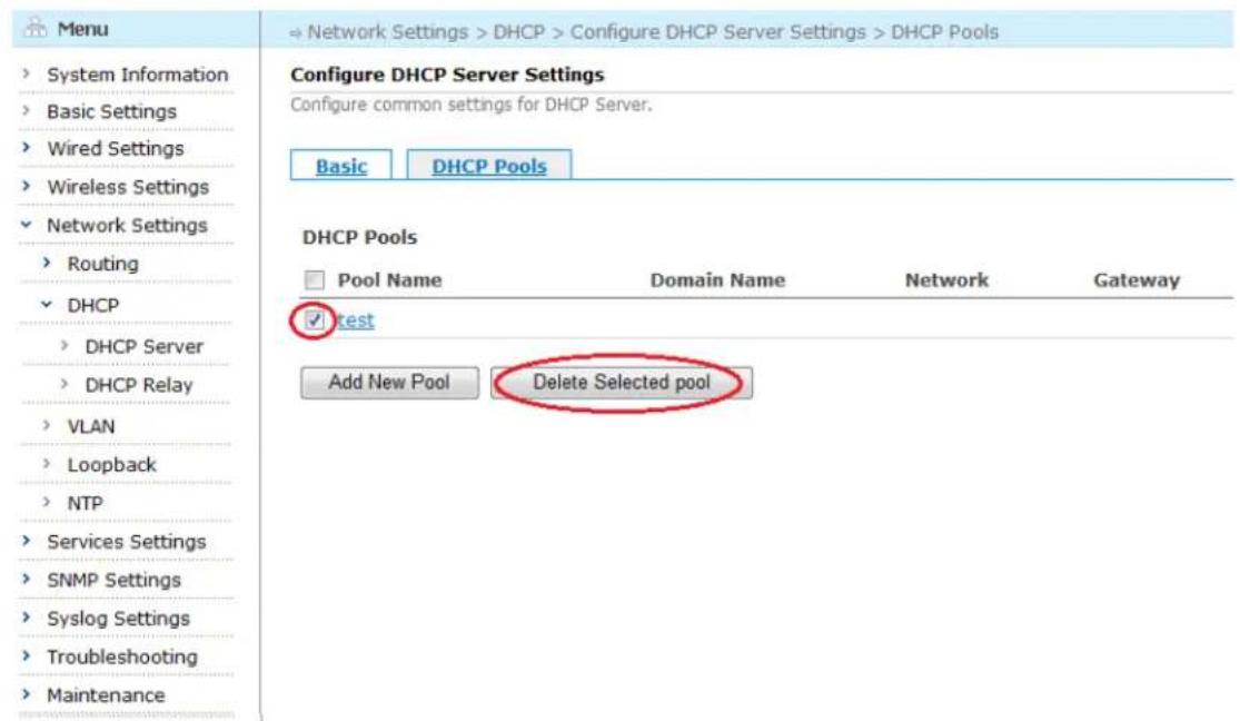
text_image
Menu System Information Basic Settings Wired Settings Wireless Settings Network Settings Routing DHCP DHCP Server DHCP Relay VLAN Loopback NTP Services Settings SNMP Settings Syslog Settings Troubleshooting Maintenance → Network Settings > DHCP > Configure DHCP Server Settings > DHCP Pools Configure DHCP Server Settings Configure common settings for DHCP Server. Basic DHCP Pools DHCP Pools Pool Name Domain Name Network Gateway Test Add New Pool Delete Selected poolFigure 6-16 Deleting an Existing DHCP Pool
6.2.5. Adding an IP Address Range
IP address ranges make up the available addresses in this DHCP pool. DHCP clients can only obtain IP addresses from these ranges. To define IP address ranges, click a pool name to open the "Edit the Pool Parameters" page, and then click the "IP Address Ranges" tab, the configuration page appears. Enter the Begin IP Address and End IP Address, click "Add IP Range" button, the IP Address range will be added to the list area.
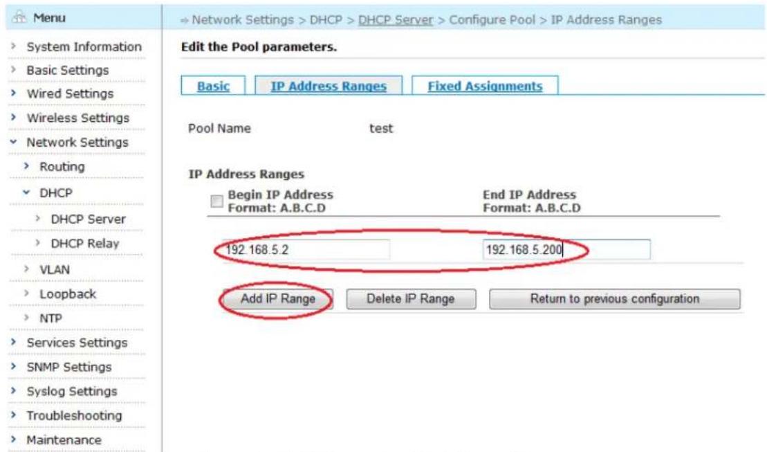
text_image
Menu System Information Basic Settings Wired Settings Wireless Settings Network Settings Routing DHCP DHCP Server DHCP Relay VLAN Loopback NTP Services Settings SNMP Settings Syslog Settings Troubleshooting Maintenance → Network Settings > DHCP > DHCP Server > Configure Pool > IP Address Ranges Edit the Pool parameters. Basic IP Address Ranges Fixed Assignments Pool Name Nu test IP Address Ranges Begin IP Address End IP Address Format: A.B.C.D Format: A.B.C.D 192.168.5.2 192.168.5.200 Add IP Range Delete IP Range Return to previous configurationFigure 6-17 Adding a New IP Address Range
Click "Return to previous configuration" button, return to the basic page of configuring DHCP Pool
6.2.6. Deleting an IP Address Range
To delete an existing IP address range, check the boxes beside the IP range to be deleted and click the "Delete IP Range" button.
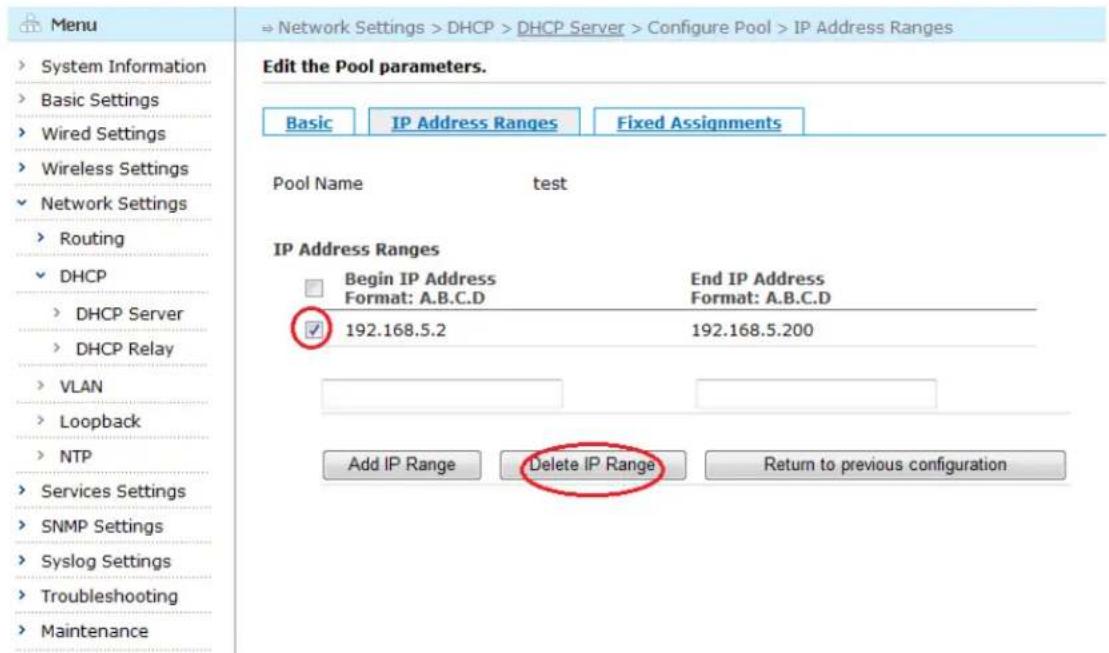
text_image
Menu System Information Basic Settings Wired Settings Wireless Settings Network Settings Routing DHCP DHCP Server DHCP Relay VLAN Loopback NTP Services Settings SNMP Settings Syslog Settings Troubleshooting Maintenance Edit the Pool parameters. Basic IP Address Ranges Fixed Assignments Pool Name Nu test IP Address Ranges Begin IP Address End IP Address Format: A.B.C.D Format: A.B.C.D ✓192.168.5.2 192.168.5.200 Add IP Range Delete IP Range.Return to previous configurationFigure 6-18 Deleting an Existing IP Address Range
6.2.7. Adding an Fixed IP Assignment
In general, the DHCP protocol assigns unused addresses arbitrarily from each DHCP pool for each client. This behavior allows the number of clients that could access the network to be greater than that of the IP addresses, as long as these clients do not connect at the same time. It also, however, causes the IP address obtained by the same client to vary from session to session. Sometimes, a network administrator or client user may have the need to obtain the same IP address at all times. To satisfy this requirement, user may specify a set of fixed IP Address assignments beneath the IP Address ranges.
Fixed IP assignments are allocated based on the MAC address of each client device. To create a fixed assignment, click the "Fixed Assignment" tab to enter the configuration page, and specify the MAC Address and the desired IP address, then click the "Add Fixed IP Assignment" button, the fixed assignment will be added to the list area, the appears:
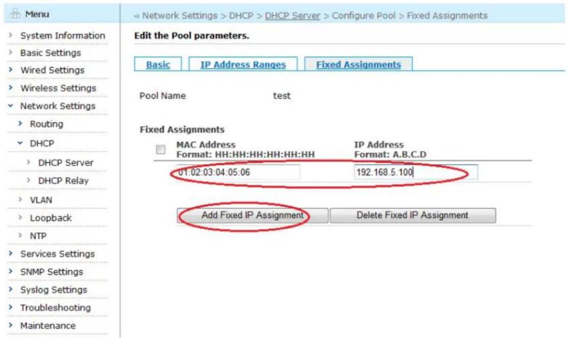
text_image
Menu System Information Basic Settings Wired Settings Wireless Settings Network Settings Routing DHCP DHCP Server DHCP Relay VLAN Loopback NTP Services Settings SNMP Settings Syslog Settings Troubleshooting Maintenance → Network Settings > DHCP > DHCP Server > Configure Pool > Fixed Assignments Edit the Pool parameters. Basic IP Address Ranges Fixed Assignments Pool Name Nu test Fixed Assignments MAC Address IP Address Format: HH:HH:HH:HH:HH Format: A.B.C.D 01.02.03.04.05.06 192.168.5.100 Add Fixed IP Assignment Delete Fixed IP AssignmentFigure 6-19 Adding an Fixed Assignment
6.2.8. Deleting an Existing Fixed Assignment
To delete an existing Fixed Assignment check the box beside it and click "Delete Fixed IP Assignment".
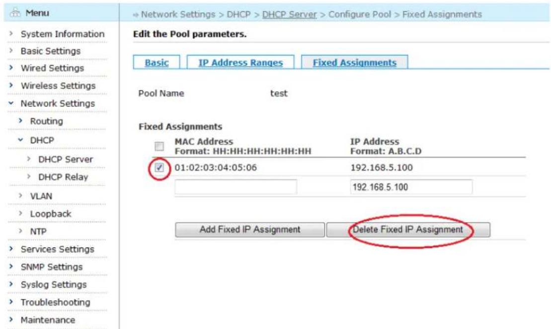
text_image
Menu System Information Basic Settings Wired Settings Wireless Settings Network Settings Routing DHCP DHCP Server DHCP Relay VLAN Loopback NTP Services Settings SNMP Settings Syslog Settings Troubleshooting Maintenance Edit the Pool parameters. Basic IP Address Ranges Fixed Assignments Pool Name Nu test Fixed Assignments MAC Address IP Address Format: HH:HH:HH:HH:HH:HH Format: A.B.C.D 01:02:03:04:05:06 192.168.5.100 192.168.5.100 Add Fixed IP Assignment Delete Fixed IP AssignmentFigure 6-20 Deleting an Existing Fixed Assignment
6.2.9. Deleting DHCP Option
To delete an existing DHCP Option, delete the content in the box beside Option 7, Option 66 and Option 151 and click "Apply Changes". To discard any changes and return to the previous page, click the "Cancel Changes" button.
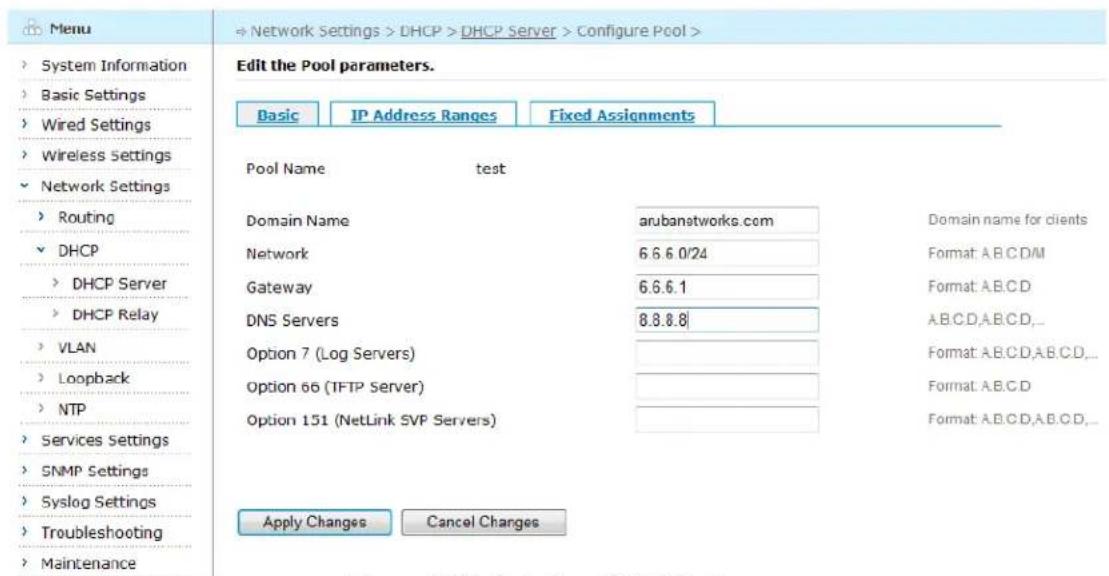
text_image
Menu System Information Basic Settings Wired Settings Wireless Settings Network Settings Routing DHCP DHCP Server DHCP Relay VLAN Loopback NTP Services Settings SNMP Settings Syslog Settings Troubleshooting Maintenance Edit the Pool parameters. Basic IP Address Ranges Fixed Assignments Pool Name test Domain Name arubanetworks.com Domain name for clients Network 6.6.6.0/24 Format: A.B.C.D/M Gateway 6.6.6.1 Format: A.B.C.D DNS Servers 8.8.8.8 A.B.C.D,A.B.C.D,... Option 7 (Log Servers) Format: A.B.C.D,A.B.C.D,... Option 66 (TFTP Server) Format: A.B.C.D Option 151 (NetLink SVP Servers) Format: A.B.C.D,A.B.C.D,... Apply Changes Cancel ChangesFigure 6-21 Deleting DHCP Option
6.2.10. DHCP Relay Configuration
DHCP Relay is a service provided by mesh routers that allows client devices connecting to the router to obtain IP Address from an external DHCP server. The mesh router relays both the DHCP request from the client to the DHCP server and the reply from the server to the client.
Select "Network Settings" > "DHCP" > "DHCP Relay" in the left-side menu tree to open the DHCP server configuration page. The "DHCP Relay configuration" page appears.
| Menu | ⇒ Network Settings > DHCP > DHCP Relay | |
| System Information | DHCP Relay Configuration | |
| Basic Settings | Configure DHCP Relay Settings. | |
| Wired Settings | DHCP Servers | Format: A.B.C.D,A.B.C.D,... |
| Wireless Settings | ||
| Network Settings | Apply Changes | |
| Routing | ||
| DHCP | ||
| DHCP Server | ||
| DHCP Relay | ||
| VLAN | ||
| Loopback | ||
| NTP | ||
| Services Settings | ||
| SNMP Settings | ||
| Syslog Settings | ||
| Troubleshooting | ||
| Maintenance | ||
Figure 6-22 DHCP Relay Configuration Page
In this page, the external DHCP Servers can be configured. Users can enter a comma-separated list of external DHCP server IP addresses and click "Apply Changes".
6.2.11. Deleting DHCP Relay
To delete an existing DHCP relay configuration, delete the IP address in the box beside DHCP Servers and click "Apply Changes".
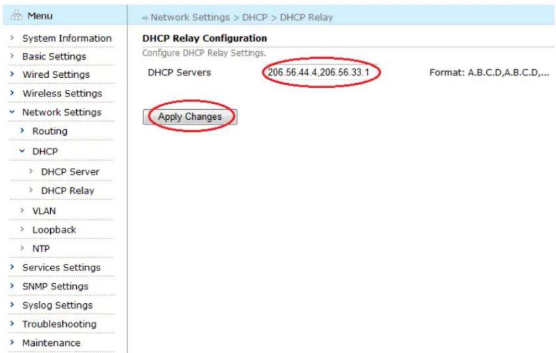
text_image
Menu System Information Basic Settings Wired Settings Wireless Settings Network Settings Routing DHCP DHCP Server DHCP Relay VLAN Loopback NTP Services Settings SNMP Settings Syslog Settings Troubleshooting Maintenance DHCP Relay Configuration Configure DHCP Relay Settings. DHCP Servers 206.56.44.4,206.56.33.1 Format: A.B.C.D,A.B.C.D,... Apply ChangesFigure 6-23 Deleting DHCP Relay Configuration
6.3. Configuring VLAN
6.3.1. VLAN Configuration
In the menu tree, select "Network Settings" > "VLAN" to bring up the VLAN configuration page.
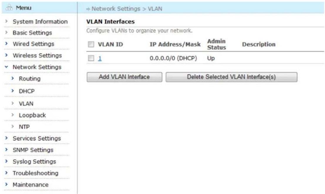
text_image
Menu System Information Basic Settings Wired Settings Wireless Settings Network Settings Routing DHCP VLAN Loopback NTP Services Settings SNMP Settings Syslog Settings Troubleshooting Maintenance VLAN Interfaces Configure VLANs to organize your network. VLAN ID IP Address/Mask Admin Status Description 1 0.0.0.0/0 (DHCP) Up Add VLAN Interface Delete Selected VLAN Interface(s)Figure 6-24 VLAN Configuration Page
6.3.2. Adding VLAN Interface
To add a new VLAN interface, click the "Add VLAN Interface" button.
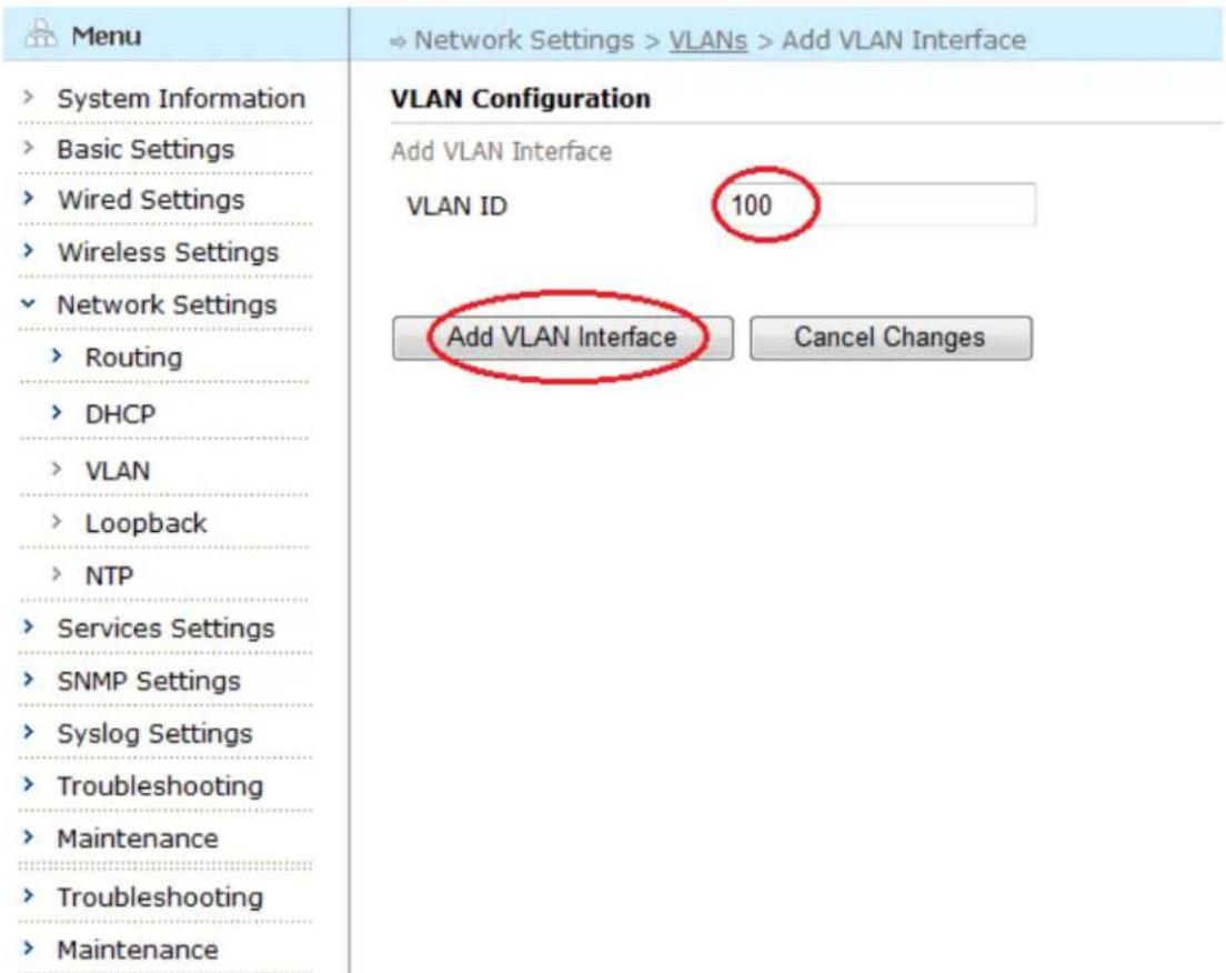
text_image
Menu System Information Basic Settings Wired Settings Wireless Settings Network Settings Routing DHCP VLAN Loopback NTP Services Settings SNMP Settings Syslog Settings Troubleshooting Maintenance Troubleshooting Maintenance VLAN Configuration Add VLAN Interface VLAN ID 100 Add VLAN Interface Cancel ChangesFigure 6-25 Add VLAN Interface Page
6.3.3. Configuring VLAN Basic Settings
Enter VLAN ID, for example "100", click "Add VLAN Interface" button, pop up the configuration page as shown in figure below.
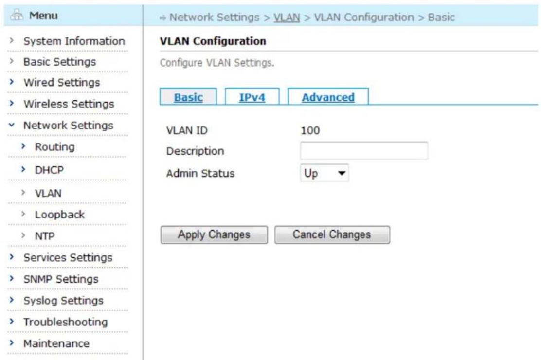
text_image
Menu System Information Basic Settings Wired Settings Wireless Settings Network Settings Routing DHCP VLAN Loopback NTP Services Settings SNMP Settings Syslog Settings Troubleshooting Maintenance VLAN Configuration Configure VLAN Settings. Basic IPv4 Advanced VLAN ID 100 Description Admin Status Up Apply Changes Cancel ChangesFigure 6-26 Basic Settings for the New VLAN Interface
Table below describes the basic settings for VLAN.
Table 6-9 VLAN Interface Basic Configuration Fields
| Setting | Explanation | Default |
| Description | Describe the VLAN interface | N/A |
| Admin Status | Can be up or down.If down, this interface would be inactive (shutdown). | Up |
Saving configuration for VLAN Basic
To save the configuration after editing the above settings, click the "Apply Changes" button. To discard any changes and return to the previous page, click the "Cancel Changes" button.
6.3.4. Configuring VLAN Interface IPv4
To configure the VLAN interface IPv4, click the "IPv4" tab to enter the IPv4 configuration page.
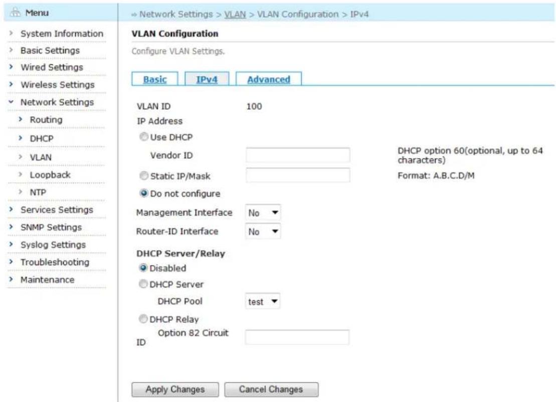
text_image
Menu System Information Basic Settings Wired Settings Wireless Settings Network Settings Routing DHCP VLAN Loopback NTP Services Settings SNMP Settings Syslog Settings Troubleshooting Maintenance VLAN Configuration Configure VLAN Settings. Basic IPv4 Advanced VLAN ID 100 IP Address Use DHCP Vendor ID DHCP option 60(optional, up to 64 characters) Static IP/Mask Format: A.B.C.D/M Do not configure Management Interface No Router-ID Interface No DHCP Server/Relay Disabled DHCP Server DHCP Pool/test DHCP Relay Option 82 Circuit ID Apply Changes Cancel ChangesFigure 6-27 IPv4 Configuration Screen
Table below describes the settings for the IPv4.
Table 6-10 VLAN Interface IPv4 Configuration Fields
| Setting | Explanation | Default |
| IP Address | 1) Use DHCP:a) Enter manufacturer ID, configure DHCP Option 60 (up to 64 characters)2) Static IP/mask: manually configure static IP/mask, format A.B.C.D/M3) Do not configure: not configure IP address | Do not configure |
| Management Interface | Whether configure this interface as Management interface | No |
| Router-ID Interface | Whether configure this interface as Router-ID interface | No |
| DHCP Server | 1) Disabled2) DHCP ServerDHCP Pool: configure DHCP address pool3) DHCP Relay: enter Option 82 Circuit ID configuration | Disabled |
Saving configuration for VLAN IPv4
To save the configuration after editing the above settings, click the "Apply Changes" button. To discard any changes and return to the previous page, click the "Cancel Changes" button.
6.3.5. VLAN Interface Advanced Configuration
To configure the VLAN advanced features, click the "Advanced" tab to enter the Advanced edit page.
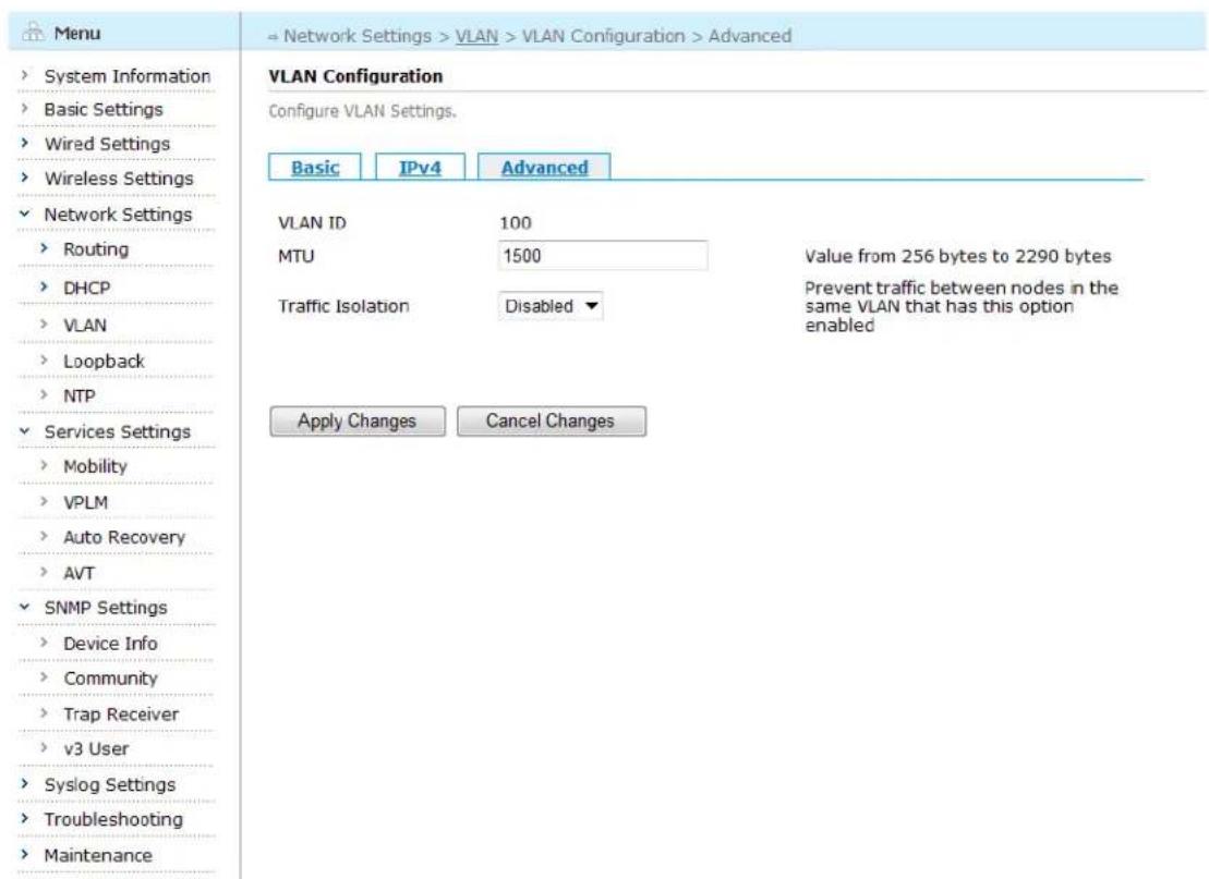
text_image
Menu System Information Basic Settings Wired Settings Wireless Settings Network Settings Routing DHCP VLAN Loopback NTP Services Settings Mobility VPLM Auto Recovery AVT SNMP Settings Device Info Community Trap Receiver v3 User Syslog Settings Troubleshooting Maintenance VLAN Configuration Configure VLAN Settings. Basic IPv4 Advanced VLAN ID 100 MTU 1500 Value from 256 bytes to 2290 bytes Traffic Isolation Disabled Prevent traffic between nodes in the same VLAN that has this option enabled Apply Changes Cancel ChangesFigure 6-28 Ethernet Interface Advanced Configuration Screen
Table below describes the settings for the advanced features.
Table 6-11 Ethernet Interface Advanced Configuration Fields
| Setting | Explanation | Default |
| MTU (Maximum Transmission Unit) | Maximum transmission unit in bytes; controls how Layer-3 packets would be fragmented when they are sent through this interface. Range: 256-1500 | 1500 |
| Traffic Isolation | Enable or disable the traffic isolation feature | Disabled |
Saving configuration for VLAN Advanced Settings
To save the configuration after editing the above settings, click the "Apply Changes" button. To discard any changes and return to the previous page, click the "Cancel Changes" button.
6.3.6. Deleting a VLAN Interface
To delete an existing VLAN interface, check the boxes beside the VLAN ID to be deleted and click the "Delete Selected VLAN Interface(s)" button.
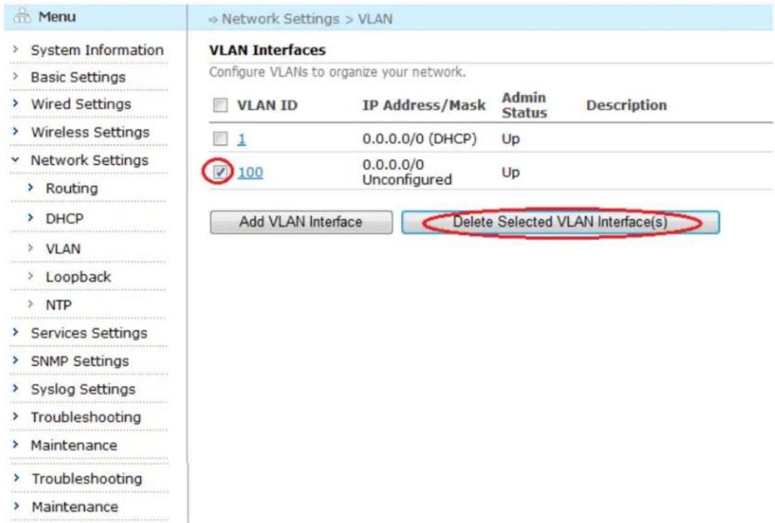
text_image
Menu System Information Basic Settings Wired Settings Wireless Settings Network Settings Routing DHCP VLAN Loopback NTP Services Settings SNMP Settings Syslog Settings Troubleshooting Maintenance Troubleshooting Maintenance VLAN Interfaces Configure VLANs to organize your network. VLAN ID IP Address/Mask Admin Status Description 1 0.0.0.0/0 (DHCP) Up ✓ 100 0.0.0.0/0 Unconfigured Up Add VLAN Interface Delete Selected VLAN Interface(s)Figure 6-29 Delete VLAN Interface(s) Page
6.4. Configuring Loopback
6.4.1. Loopback Configuration
In the menu tree, select "Network Settings" > "Loopback" to bring up the Loopback configuration page.
| Menu | → Network Settings > Loopback | ||
| System Information Basic Settings Wired Settings Wireless Settings Network Settings Routing DHCP VLAN Loopback NTP Services Settings SNMP Settings Syslog Settings Troubleshooting Maintenance | Loopback Interfaces Configure loopback interfaces to add extra layer-3 reachable IP addresses to this device | ||
| Loopback Index | IP Address/Mask | Description | |
| 0 | 10.44.81.209/32 (Generated from MAC) | ||
| Add Delete | |||
Figure 6-30 Loopback Configuration Page
6.4.2. Adding a Loopback Interface
To add a new Loopback interface, click the "Add" button. The following page appears:
| Menu | Network Settings > Loopback > Create Loopback Interface |
| System Information Basic Settings Wired Settings Wireless Settings Network Settings Routing DHCP VLAN Loopback NTP Services Settings SNMP Settings Syslog Settings Troubleshooting Maintenance | Loopback Interface Configuration Create Loopback Interface Loopback Index 0▼ Create Cancel Changes |
Figure 6-31 Adding a Loopback Interface Page
In this page, choose Loopback Index and click "Create" button, enter the Loopback configuration page:
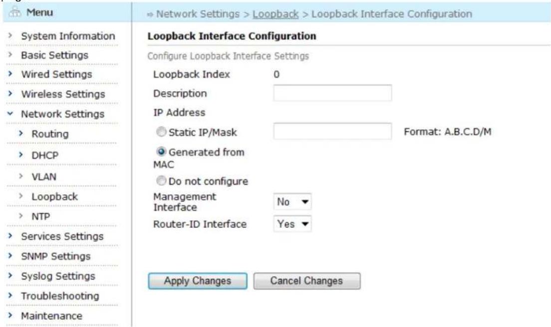
text_image
Menu System Information Basic Settings Wired Settings Wireless Settings Network Settings Routing DHCP VLAN Loopback NTP Services Settings SNMP Settings Syslog Settings Troubleshooting Maintenance Loopback Interface Configuration Configure Loopback Interface Settings Loopback Index 0 Description IP Address Static IP/Mask Format: A.B.C.D/M Generated from MAC Do not configure Management No Interface Router-ID Interface Yes Apply Changes Cancel ChangesFigure 6-32 Loopback Configuration Page
Table below describes the settings for loopback.
Aruba Mesh Router Web-based Configuration Guide
Table 6-12 Loopback Configuration Fields
| Setting | Explanation | Default |
| Description | Add the information to describe the loopback interface | N/A |
| IP Address | Configure the IP address for the loopback interface:1) Static IP/Mask2) Generated from MAC3) Do not configure | Generated from MAC |
| Management Interface | Whether configure this interface as Management interface | No |
| Router-ID Interface | Whether configure this interface as router-ID interface | No |
Saving configuration for Loopback Interface
To save the configuration after editing the above settings, click the "Apply Changes" button. To discard any changes and return to the previous page, click the "Cancel Changes" button.
6.4.3. Deleting an Existing Loopback Interface
To delete an existing loopback interface, check the boxes beside the loopback interface to be deleted and click the "Delete" button.
| Menu | ⇒ Network Settings > Loopback | ||
| System Information | Loopback Interfaces | ||
| Basic Settings | Configure loopback interfaces to add extra layer-3 reachable IP addresses to this device | ||
| Wired Settings | Loopback Index | IP Address/Mask | Description |
| Wireless Settings | ✓ 2 | 10.44.81.209/32 (Generated from MAC) | |
| Network Settings | |||
| Routing | Add Delete | ||
| DHCP | |||
| VLAN | |||
| Loopback | |||
| NTP | |||
| Services Settings | |||
| SNMP Settings | |||
| Syslog Settings | |||
| Troubleshooting | |||
| Maintenance | |||
Figure 6-33 Deleting an Existing Loopback Interface
6.5. Configuring NTP
6.5.1. NTP Configuration
In the menu tree, select "Network Settings" > "NTP" to bring up the NTP configuration page.
Aruba Mesh Router Web-based Configuration Guide
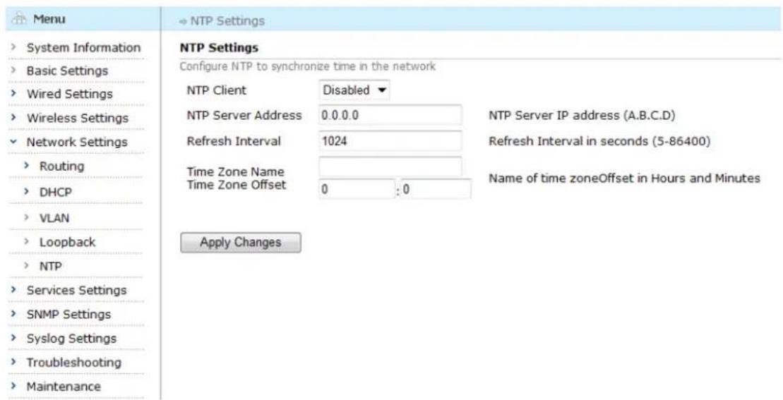
text_image
Menu System Information Basic Settings Wired Settings Wireless Settings Network Settings Routing DHCP VLAN Loopback NTP Services Settings SNMP Settings Syslog Settings Troubleshooting Maintenance NTP Settings Configure NTP to synchronize time in the network NTP Client Disabled ▼ NTP Server Address 0.0.0.0 NTP Server IP address (A.B.C.D) Refresh Interval 1024 Refresh Interval in seconds (5-86400) Time Zone Name Time Zone Offset 0 : 0 Name of time zoneOffset in Hours and Minutes Apply ChangesFigure 6-34 NTP Configuration Page
Table below describes the settings for NTP.
Table 6-13 NTP Configuration Fields
| Setting | Explanation | Default |
| NTP Client | Enable or disable NTP client | Disabled |
| NTP Server Address | Configure the IP address of NTP server, format: A.B.C. 0.0.0.0 is unset. | 0.0.0.0 |
| Refresh Interval | NTP refresh interval in seconds (5-86400) | 1024 |
| Time Zone Name | Name of time zone | |
| Time Zone Offset | Offset in hours and minutes | 0:0 |
Saving configuration for NTP
To save the configuration after editing the above settings, click the "Apply Changes" button
Chapter 7 Configuring Services
This chapter contains the following content:
- Mobility
• VPLM Configuration - Auto Recovery
- AVT
7.1. Mobility
To enter the "Mobility" configuration page, select "Services" > "Mobility" from the left-side menu tree.
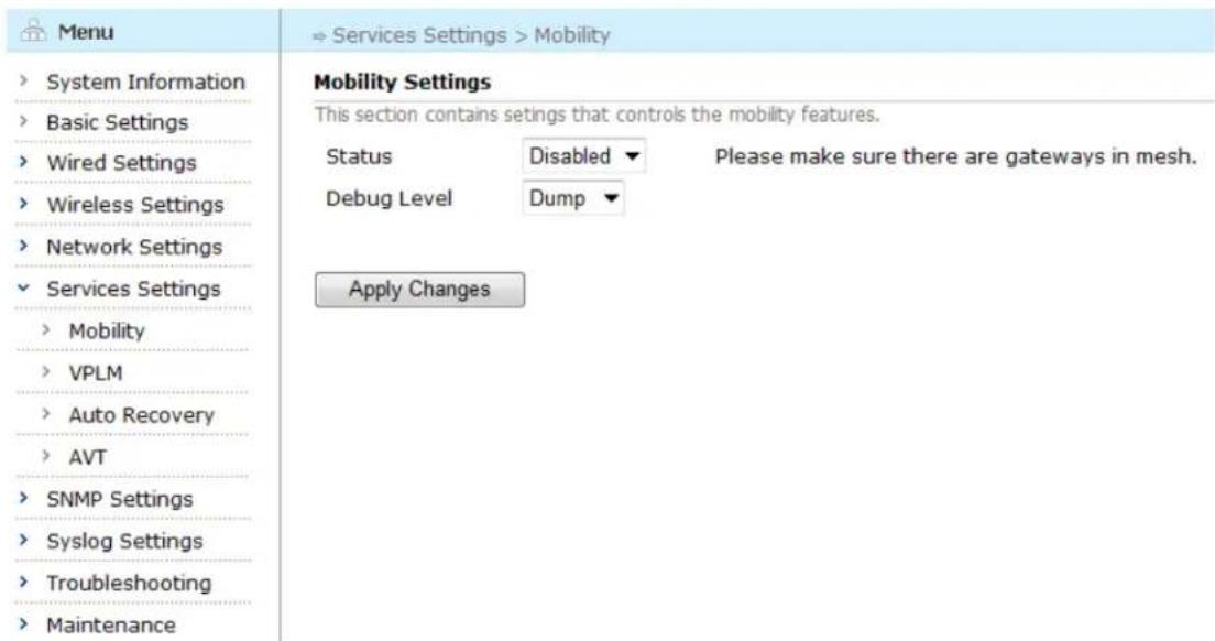
text_image
Menu System Information Basic Settings Wired Settings Wireless Settings Network Settings Services Settings Mobility VPLM Auto Recovery AVT SNMP Settings Syslog Settings Troubleshooting Maintenance → Services Settings > Mobility Mobility Settings This section contains settings that controls the mobility features. Status Disabled Please make sure there are gateways in mesh. Debug Level Dump Apply ChangesFigure 7-1 Roaming Configuration Page
The table below describes the roaming configuration fields:
Table 7-1 Roaming Configuration Fields
| Configuration | Explanation | Default |
| Status | Roaming service enabled or disabled. | Disabled |
| Debug Level | Configure the debug level. | Dump |
Saving configuration for Mobility Settings
To save the configuration after editing the above settings, click the "Apply Changes" button.
7.2. VPLM
Select "Services" > "VPLM" from the left-side menu tree to enter the "VPLM" configuration page.
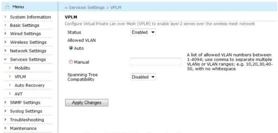
text_image
Menu System Information Basic Settings Wired Settings Wireless Settings Network Settings Services Settings Mobility VPLM Auto Recovery AVT SNMP Settings Syslog Settings Troubleshooting Maintenance VPLM Configure Virtual Private Lan over Mesh (VPLM) to enable layer-2 serves over the wireless mesh network Status Enabled Allowed VLAN Auto Manual Spanning Tree Compatibility Disabled Apply Changes A list of allowed VLAN numbers between 1-4094; use comma to separate multiple VLANs or VLAN ranges; e.g. 10,20,30,40-50, with no whitespaceFigure 7-2 VPLM Configuration Page
The table below describes the settings for VPLM.
Table 7-2 VPLM Settings
| Setting | Explanation | Default |
| Status | Whether the VPLM service is to be enabled or disabled | Enabled |
| Allowed VLAN | Configure the allowed VLAN | Auto |
| Spanning Tree Compatibility | Enable or disable Spanning Tree Compatibility | Disabled |
Saving configuration for VPLM
To save the configuration after editing the above settings, click the "Apply Changes" button.
7.3. Auto Recovery
Select "Services" > "Auto Recovery" from the left-side menu tree to enter the "Auto Recovery" configuration page.
| Menu | → Services Settings > Auto Recovery |
| System Information | Auto Recovery Enable auto recovery to allow automatic problem diagnosis and recovery. |
| Basic Settings | Status Enabled ▼ |
| Wired Settings | Debug Level Error ▼ |
| Wireless Settings | |
| Network Settings | |
| Services Settings | Apply Changes |
| Mobility | |
| VPLM | |
| Auto Recovery | |
| AVT | |
| SNMP Settings | |
| Syslog Settings | |
| Troubleshooting | |
| Maintenance |
Figure 7-3 Auto Recovery Configuration Page
The table below describes the settings for Auto Recovery.
Table 7-3 Auto Recovery Settings
| Setting | Explanation | Default |
| Status | Whether the Auto Recovery service is to be enabled or disabled. | Enabled |
| Debug Level | Configure the debug level. | Error |
Saving configuration for Auto Recovery
To save the configuration after editing the above settings, click the "Apply Changes" button.
7.4.AVT
Select "Services" > "AVT" from the left-side menu tree to enter the "AVT" configuration page.
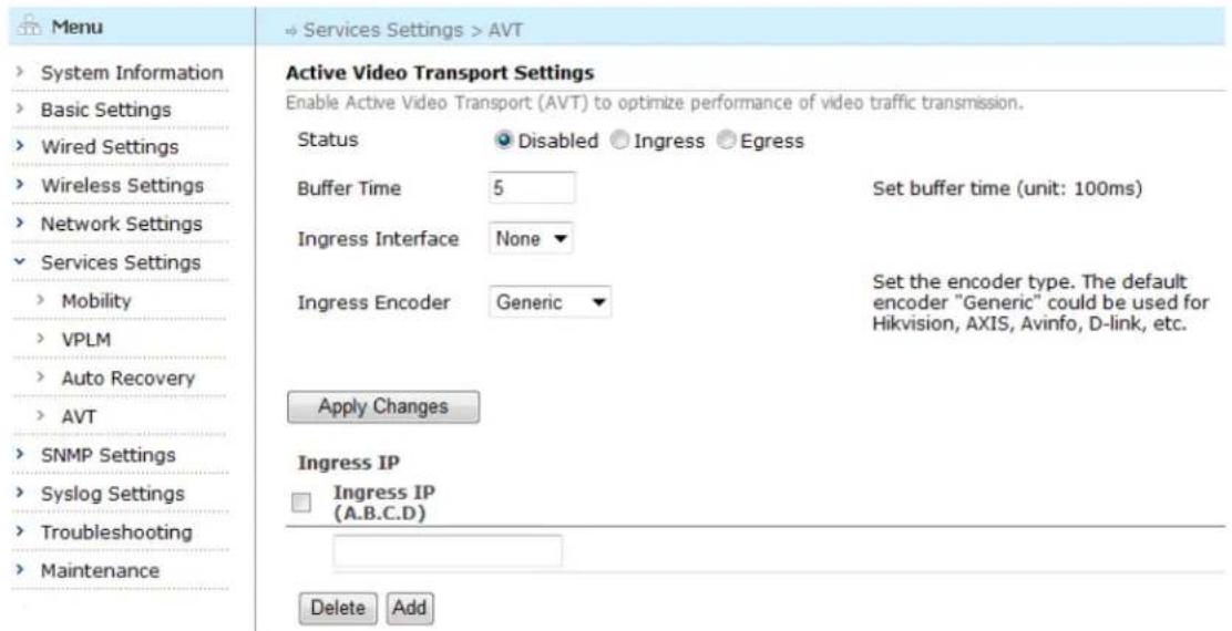
text_image
Menu > System Information > Basic Settings > Wired Settings > Wireless Settings > Network Settings > Services Settings > Mobility > VPLM > Auto Recovery > AVT > SNMP Settings > Syslog Settings > Troubleshooting > Maintenance Active Video Transport Settings Enable Active Video Transport (AVT) to optimize performance of video traffic transmission. Status Disabled Ingress Egress Buffer Time 5 Set buffer time (unit: 100ms) Ingress Interface None Ingress Encoder Generic Set the encoder type. The default encoder "Generic" could be used for Hikvision, AXIS, Avinfo, D-link, etc. Apply Changes Ingress IP Ingress IP (A.B.C.D) Delete AddFigure 7-4 AVT Configuration Page
The table below describes the settings for AVT.
Table 7-4 AVT Settings
| Setting | Explanation | Default |
| Status | Disabled: disable AVT serviceAVT Egress: enable AVT service and set the router as egressAVT Ingress: enable AVT service and set the router as ingress | Disabled |
| Buffer time | 1-100, unit is 100 milliseconds | 5 |
| Ingress interface | When a video encoder connects to the Ethernet interface of the device, the Ethernet interface can act as AVT Ingress. | None |
| Ingress Encoder | Set the encoder type (video server). Generic for most encoders (default) such as Hikvision AXIS, Avinfo and D-Link Tycosun for Tycosun encoder; and Visiondigi for Visiondigi encoder | Generic |
Saving configuration for AVT
To save the configuration after editing the above settings, click the "Apply Changes" button.
7.4.1. Adding an Ingress IP
To add an ingress IP, enter the IP address in the box and click the "Add" tab.
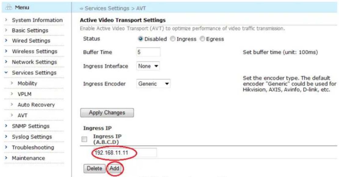
text_image
Menu > System Information > Basic Settings > Wired Settings > Wireless Settings > Network Settings > Services Settings > Mobility > VPLM > Auto Recovery > AVT > SNMP Settings > Syslog Settings > Troubleshooting > Maintenance Active Video Transport Settings Enable Active Video Transport (AVT) to optimize performance of video traffic transmission. Status Disabled Ingress Egress Buffer Time 5 Set buffer time (unit: 100ms) Ingress Interface None Ingress Encoder Generic Set the encoder type. The default encoder "Generic" could be used for Hikvision, AXIS, Avinfo, D-link, etc. Apply Changes Ingress IP Ingress IP (A.B.C.D) 192.168.11.11 Delete AddFigure 7-5 Adding an Ingress IP
7.4.2. Deleting an Existing Ingress IP
To delete an ingress IP, check the boxes beside the ingress IP to be deleted and click the "Delete" button.
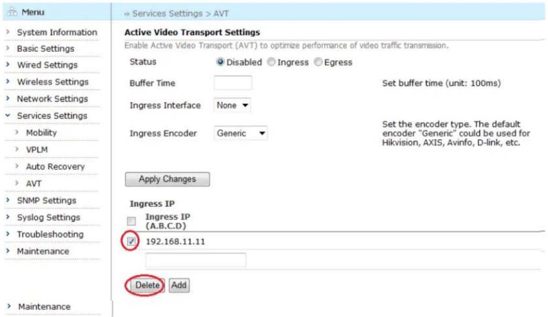
text_image
Menu System Information Basic Settings Wired Settings Wireless Settings Network Settings Services Settings Mobility VPLM Auto Recovery AVT SNMP Settings Syslog Settings Troubleshooting Maintenance Maintenance Active Video Transport Settings Enable Active Video Transport (AVT) to optimize performance of video traffic transmission. Status Disabled Ingress Egress Buffer Time Set buffer time (unit: 100ms) Ingress Interface None Ingress Encoder Generic Set the encoder type. The default encoder "Generic" could be used for Hikvision, AXIS, Avinfo, D-link, etc. Apply Changes Ingress IP Ingress IP (A.B.C.D) 192.168.11.11 Delete AddFigure 7-6 Deleting an Existing Ingress IP
Chapter 8 SNMP Configuration
Wireless mesh routers all provide remote management through the popular Simple Network Management Protocol (SNMP). Using SNMP, network management products can read/write configuration and store data on the wireless mesh routers.
This chapter describes how SNMP service can be configured using the web-based management interface. It includes the following sections:
- Configuring Device Information
- Configuring SNMP Communities
- Configuring SNMP Trap Receivers
- Configuring SNMPv3 User Accounts
8.1. Device Info
Select "SNMP" > "Device Info" from the left-side menu tree to enter "Device Info" configuration page. The resulting page is shown below. It displays all of the configured SNMP location and contact information.
| Menu | SNMP > Device Info | |
| System Information | Device Info | |
| Basic Settings | Configure general SNMP settings | |
| Wired Settings | Sysname | |
| Wireless Settings | Syslocation | BeiJing |
| Network Settings | Syscontact | support@arubanetworks.c |
| Services Settings | ||
| SNMP Settings | Apply Changes | |
| Device Info | ||
| Community | ||
| Trap Receiver | ||
| v3 User | ||
| Syslog Settings | ||
| Troubleshooting | ||
| Maintenance | ||
Figure 8-1 SNMP Device Info Page
The table below describes the SNMP device info fields.
Table 8-1 SNMP Device Info Fields
| Setting | Explanation | Default |
| Sysname | System Name | N/A |
| Syslocation | SNMP Agent location | Beijing |
| Syscontact | SNMP Agent contact info | support@arubanetworks.com |
Saving configuration for SNMP Device Info
To save the configuration after editing the above settings, click the "Apply Changes" button.
8.2. SNMP Communities
SNMP Communities is the basic authentication scheme used by SNMP v1 and v2. Each mesh router may have one or more community strings defined; each string can have an access-mode of read-only or read-write. When the router receives an SNMP command (which is usually a read or a write), it allows the operation if it matches a known community string with a matching access-mode.
8.2.1. Configuring SNMP Communities
Select "SNMP" > "Communities" from the left-side menu tree to enter "SNMP Communities" configuration page. The resulting page displays all of the configured communities and their access modes in a table.
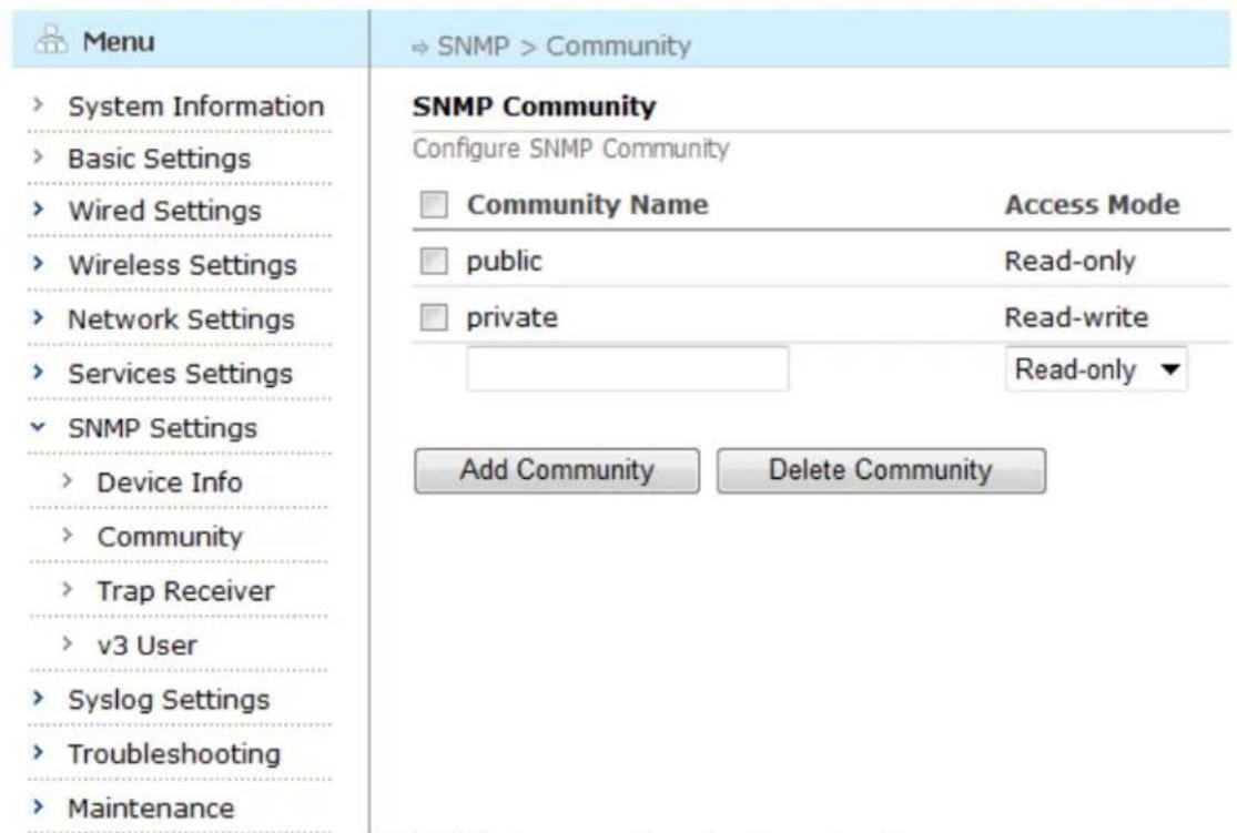
text_image
Menu System Information Basic Settings Wired Settings Wireless Settings Network Settings Services Settings SNMP Settings Device Info Community Trap Receiver v3 User Syslog Settings Troubleshooting Maintenance SNMP Community Configure SNMP Community Community Name Access Mode public Read-only private Read-write Read-only ▼ Add Community Delete CommunityFigure 8-2 SNMP Communities Configuration Page
8.2.2. Adding a New Community
To add a community, enter the community name in the box at the bottom of the table and select access mode from the drop-down menu, and then click the "Add Community" button.
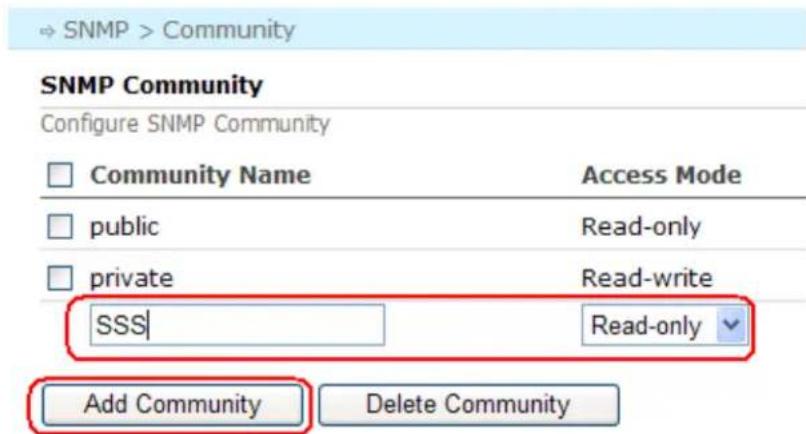
text_image
SNMP > Community SNMP Community Configure SNMP Community □ Community Name Access Mode □ public Read-only □ private Read-write SSS| Read-only Add Community Delete CommunityFigure 8-3 Add New Community Page
The community name must be an alphanumeric string that starts with a letter and has no spaces.
8.2.3. Deleting a Community
To delete a Community, check the boxes beside each entry to be deleted, and click the "Delete Community" button.
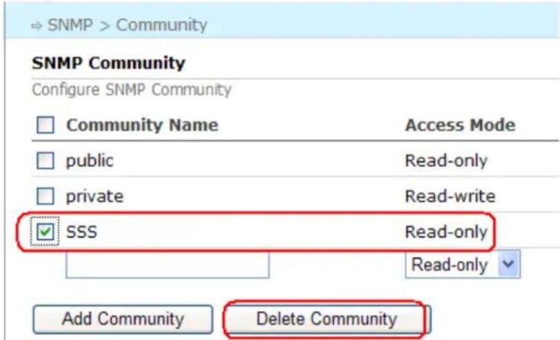
text_image
SNMP > Community SNMP Community Configure SNMP Community Community Name Access Mode public Read-only private Read-write ✓ SSS Read-only Read-only Add Community Delete CommunityFigure 8-4 Deleting a Community
8.3. SNMP Trap Receivers
SNMP Trap Receivers are external hosts that receive the SNMP trap message sent by the MESH ROUTER product. These receivers are generally Network Management Systems. Currently, only SNMPv1 and v2 trap messages are supported. Each MESH ROUTER product may configure several receivers.
Aruba Mesh Router Web-based Configuration Guide
8.3.1. Configuring SNMP Trap Receivers
Select "SNMP" > "Trap Receivers" from the left-side menu tree to open the "SNMP Trap Receivers" configuration page. The resulting page displays all of the configured receivers with their ports and communities in a table.
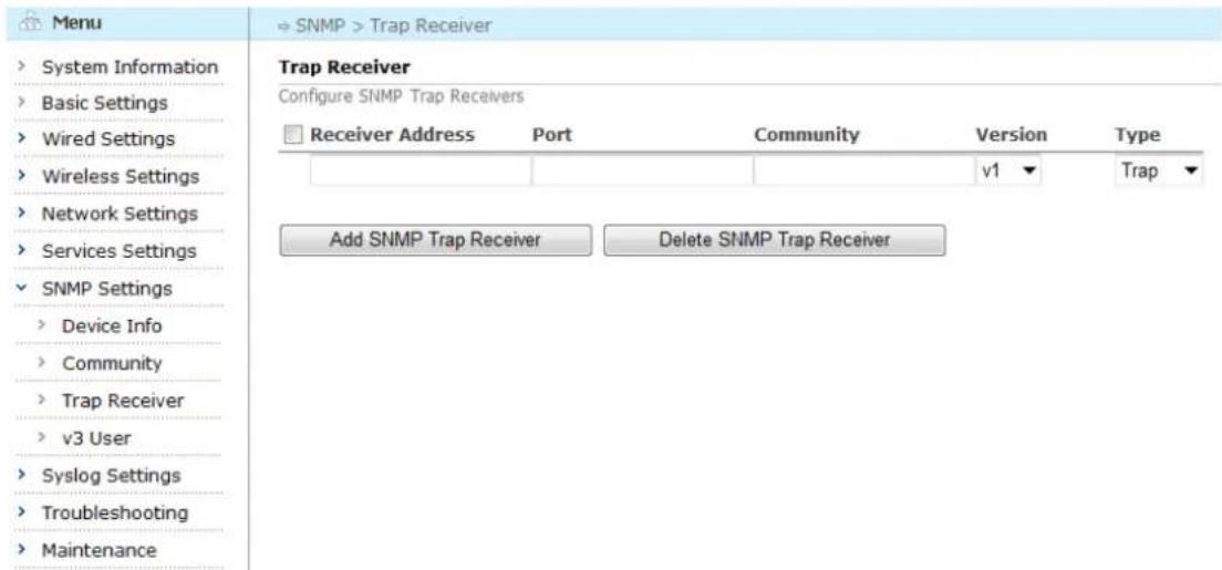
text_image
Menu System Information Basic Settings Wired Settings Wireless Settings Network Settings Services Settings SNMP Settings Device Info Community Trap Receiver v3 User Syslog Settings Troubleshooting Maintenance Trap Receiver Configure SNMP Trap Receivers Receiver Address Port Community Version Type Add SNMP Trap Receiver Delete SNMP Trap ReceiverFigure 8-5 SNMP Trap Receivers Configuration Page
8.3.2. Adding a New Receiver
To add a receiver, enter the Receiver Address, Port and Community in the corresponding boxes at the bottom of the table and choose Version and Type from the drop-down menu, and then click the "Add SNMP Trap Receiver" button.
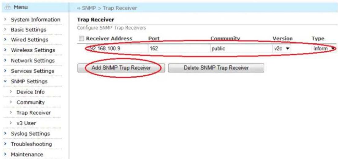
text_image
Menu System Information Basic Settings Wired Settings Wireless Settings Network Settings Services Settings SNMP Settings Device Info Community Trap Receiver v3 User Syslog Settings Troubleshooting Maintenance Trap Receiver Configure SNMP Trap Receivers Receiver Address Port Community Version Type 192.168.100.9 162 public v2c Inform Add SNMP Trap Receiver Delete SNMP Trap ReceiverFigure 8-6 Add New Trap Receiver Page
The Table below summarizes the settings for an SNMP Trap Receiver.
Table 8-2 SNMP Trap Receiver Settings
| Setting | Explanation | Default |
| Receiver Address | The IP Address for the trap receiver. | N/A |
| Port | The port number at which the trap receiver would receive the trap messages. | N/A |
| Trap Community | The community string for the trap messages sent to this receiver. The community must be alphanumeric, starting with a letter, and contain no spaces. | N/A |
| Version | The version of the trap receiver. V1 and V2C are available. | v1 |
| Message Type | The message type of the trap receiver. Trap and Inform are available. | Trap |
Note: The Version V1 cannot be configured with the message type Inform at the same time.
8.3.3. Deleting a Trap Receiver
To delete a trap receiver, check the boxes beside each receiver to be deleted, and click the "Delete SNMP Trap Receiver" button.
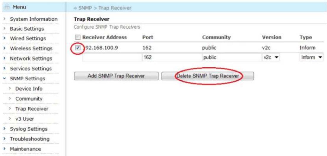
text_image
Menu ► System Information ► Basic Settings ► Wired Settings ► Wireless Settings ► Network Settings ► Services Settings ► SNMP Settings ► Device Info ► Community ► Trap Receiver ► v3 User ► Syslog Settings ► Troubleshooting ► Maintenance ► SNMP > Trap Receiver Trap Receiver Configure SNMP Trap Receivers Receiver Address Port Community Version Type ✓ 92.168.100.9 162 public v2c Inform 162 public v2c▼ Inform▼ Add SNMP Trap Receiver Delete SNMP Trap ReceiverFigure 8-7 Deleting a Trap Receiver
8.4. SNMP v3 Users
SNMPv3 introduced the concept of user accounts along with strong encryption and authentication methods. MESH ROUTER products support SNMPv3 and allow the configuration of multiple SNMPv3 users, each with different access rights as well as authentication and encryption methods.
8.4.1. Configuring SNMPv3 Users
Choose "SNMP" > "V3 Users" from the left-side menu tree to open the "SNMPv3 Users"
Aruba Mesh Router Web-based Configuration Guide
configuration page. The resulting page displays all of the configured v3 users and their information.
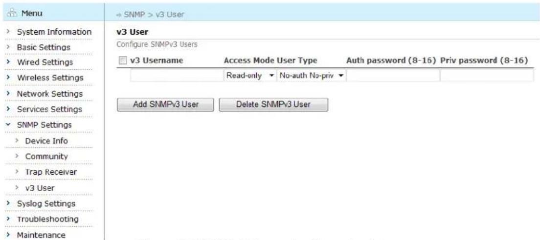
text_image
Menu System Information Basic Settings Wired Settings Wireless Settings Network Settings Services Settings SNMP Settings Device Info Community Trap Receiver v3 User Syslog Settings Troubleshooting Maintenance v3 User Configure SNMPv3 Users v3 Username Access Mode User Type Auth password (8-16) Priv password (8-16) Read-only No-auth No-priv Add SNMPv3 User Delete SNMPv3 UserFigure 8-8 SNMPv3 Users Configuration Page
8.4.2. Adding a New v3 User
To add a new v3 user, enter the v3 Username, Auth password and Priv password in the corresponding boxes and choose Access Mode and User Type from the drop-down menu, and then click the "Add SNMPv3 User" button at the bottom of the table.
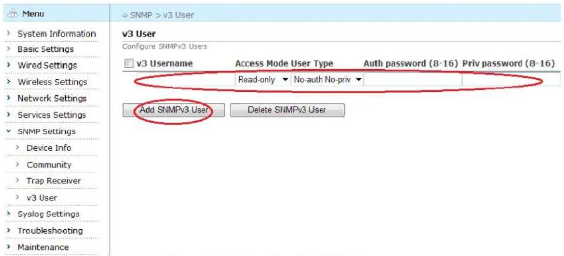
text_image
Menu → SNMP > v3 User v3 User Configure SNMPv3 Users v3 Username Access Mode User Type Auth password (8-16) Priv password (8-16) Read-only ▼ No-auth No-priv ▼ Add SNMPv3 User Delete SNMPv3 UserFigure 8-9 Add a New SNMPv3 Users
The table below summarizes the settings for a SNMPv3 user.
Table 8-3 SNMPv3 User Settings
| Setting | Explanation | Default |
| V3 Username | The SNMPv3 User Name; must be an alphanumeric string, start with a letter, and contain no spaces. | N/A |
| Access Mode | Can be Read-only or Read-write | Read-only |
Aruba Mesh Router Web-based Configuration Guide
| Read-only: the user may retrieve information from the router MIB, but not change itRead-write: the user may both retrieve and change information in the router MIB. | ||
| User Type | The authentication and encryption methods used by this v3 user; can be NoAuthNoPriv, AuthNoPriv, or AuthPriv.NoAuthNoPriv: No secure authentication or encryptionAuthNoPriv: Use secure authentication, but do not use encryption.AuthPriv: Use both secure authentication and encryption | No-auth No-priv |
| Auth Password | The authentication password used for AuthNoPriv and AuthPriv users. Must be an alphanumeric string between 8 and 16 characters long.Example: a1a2a3a4a5 | N/A |
| Priv Password | The encryption password used for AuthPriv users. Must be an alphanumeric string between 8 and 16 characters long.Example: a1a2a3a4a5 | N/A |
8.4.3. Deleting an SNMPv3 User
To delete a SNMPv3 User, check the boxes beside each user to be deleted, and click the "Delete SNMP v3 User" button.
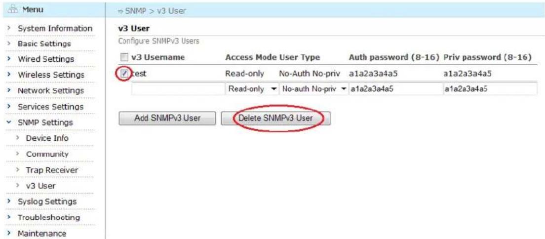
text_image
Menu ⇒ SNMP > v3 User v3 User Configure SNMPv3 Users □ v3 Username Access Mode User Type Auth password (8-16) Priv password (8-16) ✓ Test Read-only No-Auth No-priv a1a2a3a4a5 a1a2a3a4a5 Read-only No-auth No-priv a1a2a3a4a5 a1a2a3a4a5 Add SNMPv3 User Delete SNMPv3 UserFigure 8-10 Deleting an SNMPv3 User
Chapter 9 Syslog Configuration
Wireless mesh routers use syslog feature to automatically send the important local system events to the remote syslog server.
9.1. Configuring Syslog Client
Choose "Syslog" > "Client" from the left-side menu tree to open the "Syslog Client Configuration" page. The resulting page displays all of the configured syslog server and facilities/severity levels.
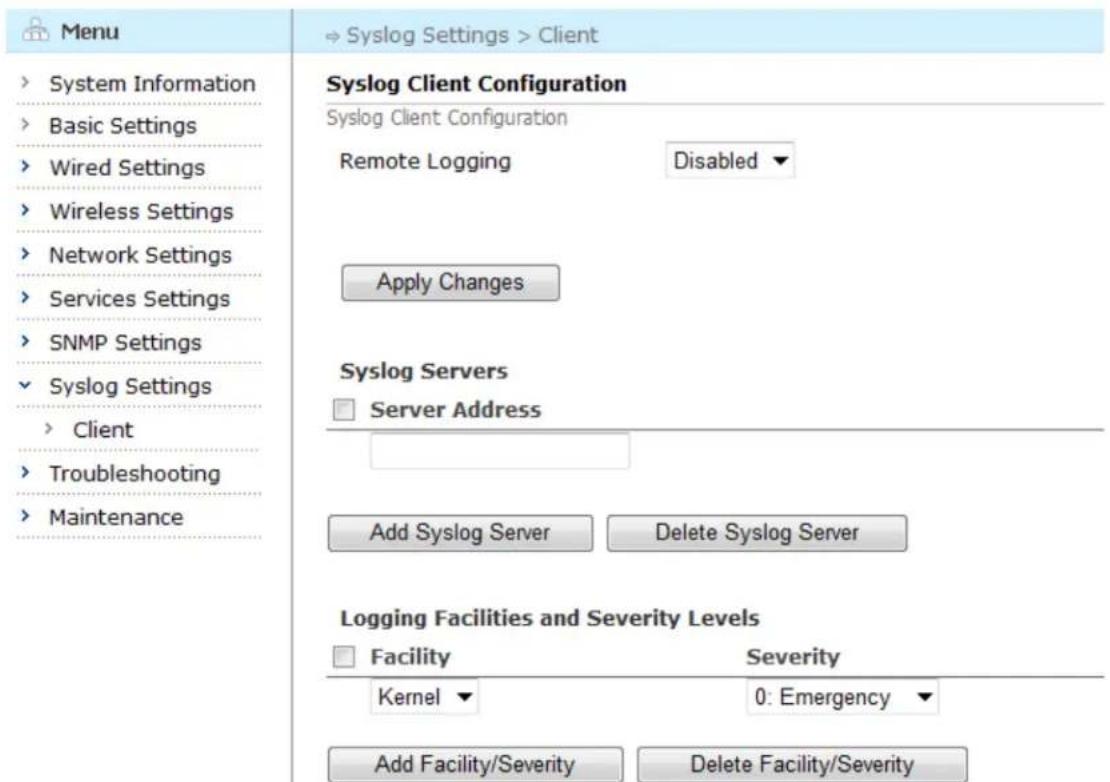
text_image
Menu System Information Basic Settings Wired Settings Wireless Settings Network Settings Services Settings SNMP Settings Syslog Settings Client Troubleshooting Maintenance Syslog Client Configuration Syslog Client Configuration Remote Logging Disabled ▼ Apply Changes Syslog Servers □ Server Address Add Syslog Server Delete Syslog Server Logging Facilities and Severity Levels □ Facility Severity Kernel ▼ 0: Emergency ▼ Add Facility/Severity Delete Facility/SeverityFigure 9-1 Syslog Client Configuration Page
9.2. Remote Syslog Service
Choose the "Enabled" or "Disabled" from the drop-down menu beside the Remote Logging, and click "Apply Changes" button.
→ Syslog Settings > Client
Syslog Client Configuration
Syslog Client Configuration
Remote Logging
Disabled
Apply Changes
Figure 9-2 Changing Syslog Client Configuration
9.3. Adding a Syslog Server
To add a syslog server, enter the server address in the box at the bottom of the syslog server list, and click "Add Syslog Server" button.
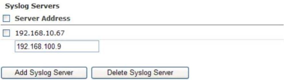
text_image
Syslog Servers □ Server Address □ 192.168.10.67 192.168.100.9 Add Syslog Server Delete Syslog ServerFigure 9-3 Adding an Syslog Server
9.4. Deleting a Syslog Server
To delete a syslog server, check the boxes beside each server to be deleted, and click the "Delete Syslog Server" button.
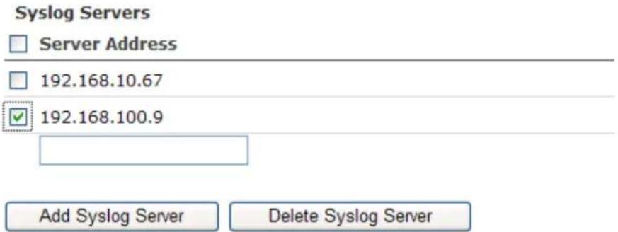
text_image
Syslog Servers □ Server Address □ 192.168.10.67 ✓ 192.168.100.9 Add Syslog Server Delete Syslog ServerFigure 9-4 Deleting a Syslog Server
9.5. Adding Facility and Severity Level
To add facility and severity level, choose the facility and severity level from the drop-down menu, and click "Add Facility/Severity" button.
Logging Facilities and Severity Levels
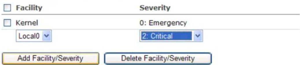
text_image
Facility Severity Kernel 0: Emergency Local0 2: Critical Add Facility/Severity Delete Facility/SeverityFigure 9-5 Adding Facility and Severity Level
9.6. Deleting Facility and Severity
To delete facility/severity, check the boxes beside each facility/severity to be deleted, and click the "Delete Facility/Severity" button.
Logging Facilities and Severity Levels
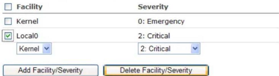
text_image
Facility Severity Kernel 0: Emergency ✓ Local0 2: Critical Kernel 2: Critical Add Facility/Severity Delete Facility/SeverityFigure 9-6 Deleting Facility/Severity
Chapter 10 Troubleshooting
Wireless mesh routers provide some tools for network diagnosis, including:
- Tools
- Logs
10.1. Tools
The Tools page provides many common tools to see the working status and performance of routers.
Click "Troubleshooting" -> "Tools" to enter Tools page.
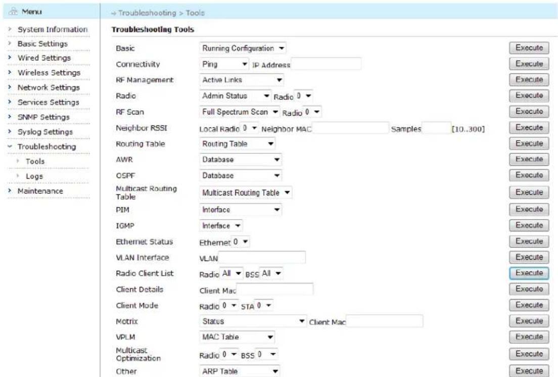
text_image
Menu System Information Basic Settings Wired Settings Wireless Settings Network Settings Services Settings SNMP Settings Syslog Settings Troubleshooting Tools Logs Maintenance Troubleshooting Tools Basic Running Configuration ▼ Connectivity Ping IP Address RF Management Active Links ▼ Radio Admin Status Radio 0 ▼ RF Scan Full Spectrum Scan Radio 0 ▼ Neighbor RSSI Local Radio 0 ▼ Neighbor MAC Samples [10..300] Routing Table Routing Table ▼ AWR Database ▼ OSPF Database ▼ Multicast Routing Table Multicast Routing Table ▼ PIM Interface ▼ IGMP Interface ▼ Ethernet Status Ethernet 0 ▼ VLAN Interface VLAN Radio Client List Radio All BSS All ▼ Client Details Client Mac Client Mode Radio 0 STA 0 ▼ Motrix Status Client Mac VPLM MAC Table ▼ Multicast Radio 0 BSS 0 ▼ Optimization Other ARP Table ▼Figure 10-1 Troubleshooting Tools Page
The table below describes the information of these troubleshooting tools.
Table 10-1 Troubleshooting Tools Information
| Troubleshooting Tools | Explanation |
| Basic | Obtain the device's basic information, including running configuration file, startup configuration file, mesh node list, interface list, hardware inventory |
| Connectivity | Tools to check connectivity, including Ping and Traceroute |
| RF Management | RF management status, including active links, active portals, qualified neighbors and all neighbors |
| Radio | View radio interfaces information, including radio status and scanned device |
Aruba Mesh Router Web-based Configuration Guide
| RF Scan | View the neighbors of radio interfaces after full spectrum scan |
| Neighbor RSSI | View the neighbor RSSI status continuously according to local radio index and neighbor MAC address |
| Routing Table | View routing table, including AWR route, connected route, OSPF route, static route and route summary |
| AWR | View AWR database and neighbor information |
| OSPF | View OSPF database, interfaces and neighbor information |
| Multicast Routing Table | View the Multcast Routing table |
| PIM | View the PIM interface or neighbor status |
| IGMP | View the IGMP group member or interface status |
| Ethernet Status | View Ethernet interface status |
| VLAN Interface | View VLAN interface status |
| Radio Client List | View the Radio client list according to radio index and BSS index |
| Client Details | View the client detailed information according to client MAC address |
| Client Mode | View client modes according to radio index and station index |
| Motrix | View Motrix roaming information, including status, interfaces, local client list, LMS client list, TGW client list, specified clients (specified MAC addresses) roaming information |
| VPLM | View VPLM information, including VPLM MAC table and VPLM database |
| Multicast Optimization | View which station connected is enable Multicast Optimization |
| Other | View ARP table and DHCP server lease address and AVT status |
For example, Ping is a common tool used to check the reachability to destination network.
Click "Tools" -> "Connectivity" -> "Ping" to enter Ping page, and enter IP address to ping in the box beside "IP Address".
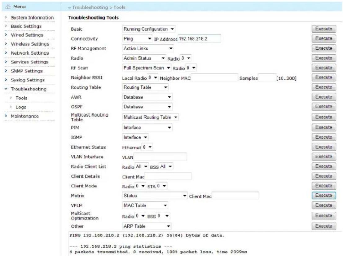
text_image
Menu System Information Basic Settings Wired Settings Wireless Settings Network Settings Services Settings SNMP Settings Syslog Settings Troubleshooting Tools Logs Maintenance Troubleshooting Tools Basic Running Configuration ▼ Connectivity Ping ▼ IP Address 192.168.218.2 RF Management Active Links ▼ Radio Admin Status ▼ Radio 0 ▼ RF Scan Full Spectrum Scan ▼ Radio 0 ▼ Neighbor RSSI Local Radio 0 ▼ Neighbor MAC Samples [10..300] Routing Table Routing Table ▼ AWR Database ▼ OSPF Database ▼ Multicast Routing Table Multicast Routing Table ▼ PIM Interface ▼ IGMP Interface ▼ Ethernet Status Ethernet 0 ▼ VLAN Interface VLAN Radio Client List Radio All ▼ BSS All ▼ Client Details Client Mac Client Mode Radio 0 ▼ STA 0 ▼ Motrix Status ▼ Client Mac VPLM MAC Table ▼ Multicast Radio 0 ▼ BSS 0 ▼ Other ARP Table ▼ PING 192.168.218.2 (192.168.218.2) 56(84) bytes of data. --- 192.168.218.2 ping statistics --- 4 packets transmitted, 0 received, 100% packet loss, time 2999msFigure 10-2 Ping IP Address Page
Click "Execute" button, the device sends 4 packets. The result of Ping will be displayed at the bottom of this page.
10.2. Logs
MESH ROUTER products provide many types of logs, including system log, upgrade log, boot log, and etc. Click "Troubleshooting" -> "Logs" from the left-side menu tree to enter Logs page.
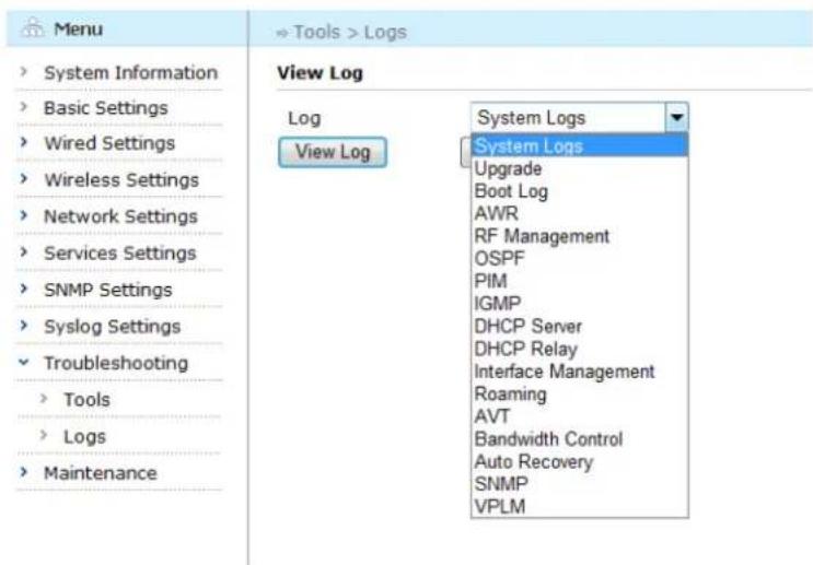
text_image
Menu System Information Basic Settings Wired Settings Wireless Settings Network Settings Services Settings SNMP Settings Syslog Settings Troubleshooting Tools Logs Maintenance View Log Log System Logs View Log System Logs Upgrade Boot Log AWR RF Management OSPF PIM IGMP DHCP Server DHCP Relay Interface Management Roaming AVT Bandwidth Control Auto Recovery SNMP VPLMFigure 10-3 Logs Page
10.2.1. Viewing Logs
Choose the log type from the drop-down menu beside the "Log" and click "View Log" button.
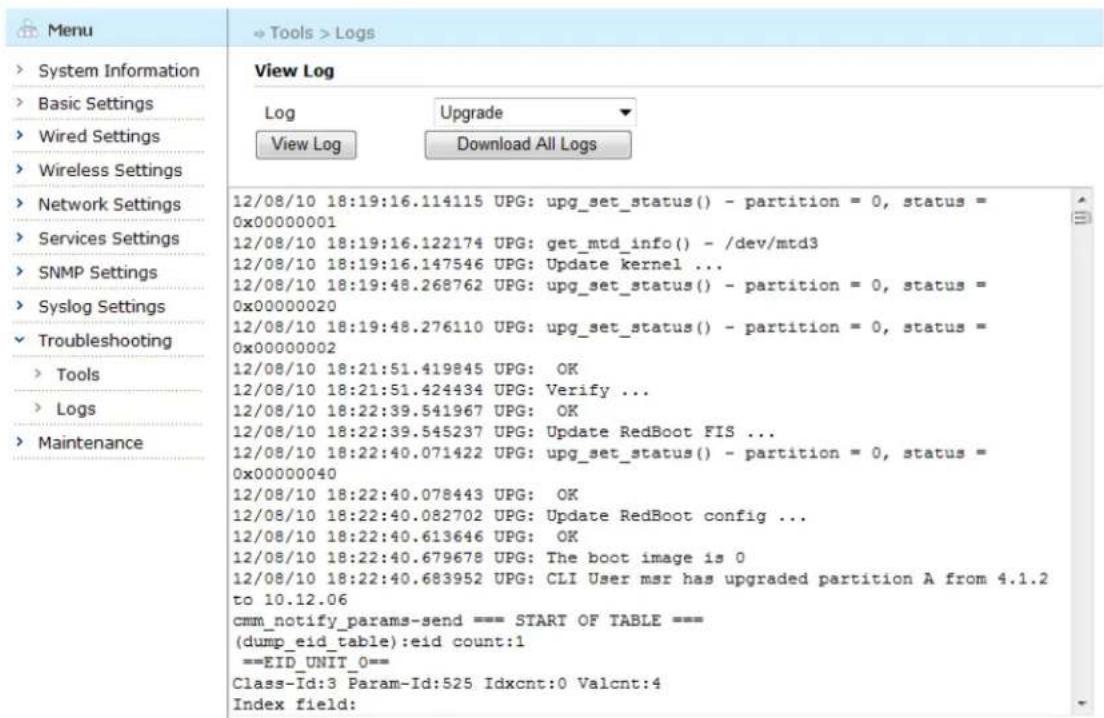
text_image
Menu System Information Basic Settings Wired Settings Wireless Settings Network Settings Services Settings SNMP Settings Syslog Settings Troubleshooting Tools Logs Maintenance View Log Log Upgrade View Log Download All Logs 12/08/10 18:19:16.114115 UPG: upg_set_status() - partition = 0, status = 0x00000001 12/08/10 18:19:16.122174 UPG: get_mtd_info() - /dev/mtd3 12/08/10 18:19:16.147546 UPG: Update kernel ... 12/08/10 18:19:48.268762 UPG: upg_set_status() - partition = 0, status = 0x00000020 12/08/10 18:19:48.276110 UPG: upg_set_status() - partition = 0, status = 0x00000002 12/08/10 18:21:51.419845 UPG: OK 12/08/10 18:21:51.424434 UPG: Verify ... 12/08/10 18:22:39.541967 UPG: OK 12/08/10 18:22:39.545237 UPG: Update RedBoot FIS ... 12/08/10 18:22:40.071422 UPG: upg_set_status() - partition = 0, status = 0x00000040 12/08/10 18:22:40.078443 UPG: OK 12/08/10 18:22:40.082702 UPG: Update RedBoot config ... 12/08/10 18:22:40.613646 UPG: OK 12/08/10 18:22:40.679678 UPG: The boot image is 0 12/08/10 18:22:40.683952 UPG: CLI User msr has upgraded partition A from 4.1.2 to 10.12.06 cmm_notify_params-send === START OF TABLE === (dump_eid_table):eid count:1 ===EID_UNIT_0== Class-Id:3 Param-Id:525 Idxcnt:0 Valcnt:4 Index field:Figure 10-4 Viewing Log Result Page
10.2.2. Downloading Logs
To download logs, select the logs to download and click "Download All Logs" button.
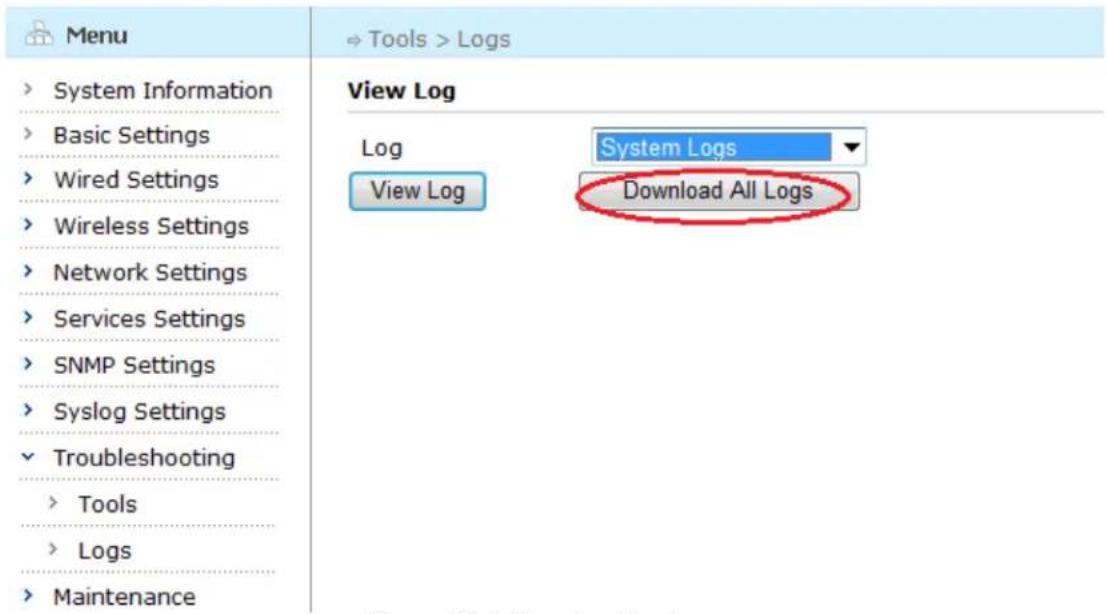
text_image
Menu System Information Basic Settings Wired Settings Wireless Settings Network Settings Services Settings SNMP Settings Syslog Settings Troubleshooting Tools Logs Maintenance View Log Log System Logs View Log Download All LogsFigure 10-5 Downloading Logs
Chapter 11 Maintenance
This chapter describes the maintenance operation provided by wireless mesh routers, including:
- Upgrade
- Import/Export
- Reboot
- Factory Reset
- Change Password
11.1. Upgrade
Wireless mesh routers can be easily upgraded by downloading an updated software image file and upgrading a MESH ROUTER's on-board software with it. To upgrade the MESH ROUTER, click on the menu tree item "Upgrade" to open the "Upgrade" page. Enter the location of the image file or click the "Browse" button to choose the image file.
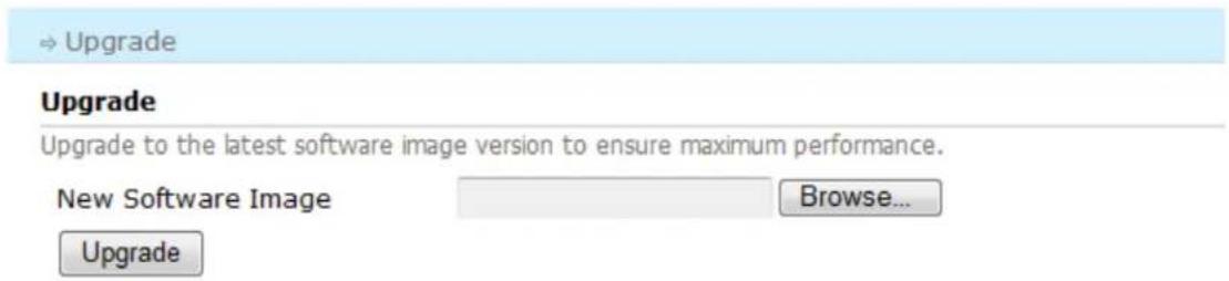
text_image
Upgrade Upgrade Upgrade to the latest software image version to ensure maximum performance. New Software Image Browse... UpgradeFigure 11-1 Upgrade Page
Click "Upgrade" button, the device start the upgrading process.
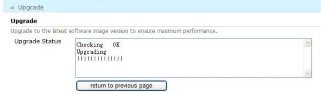
text_image
Upgrade Upgrade to the latest software image version to ensure maximum performance. Upgrade Status Checking OK Upgrading | return to previous pageFigure 11-2 Upgrading Process Page
After the upgrading complete successfully, click "Reboot" button.
Upgrade
Upgrade
Upgrade to the latest software image version to ensure maximum performance.
Upgrade Status
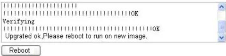
text_image
Verifying Upgrated ok,Please reboot to run on new image.Figure 11-3 Upgrading Successfully Page
Then, the system enters reboot process, click "Yes, perform reboot" button.
→ Maintenance > Reboot
Reboot Device

There may be unsaved configuration changes. Proceed with device reboot?
Yes, perform reboot
No, return to home page
Figure 11-4 Reboot Device Page
Note: The device must be rebooted to run the new image.
11.2. Import/Export Configuration
To ensure the stability of the device, we recommend users to backup the configuration file when the configuration is changed. And users should also periodically backup the configuration file of routers.
11.2.1. Export Configuration
To export the current configuration file, click "Maintenance" > "Import/Export" to enter the configuration page, Click "Export Current Configuration" button and choose the location from the pop-up window to save the configuration file. Before exporting the configuration file, check the box in front of "Save Recent Changes Before Export".
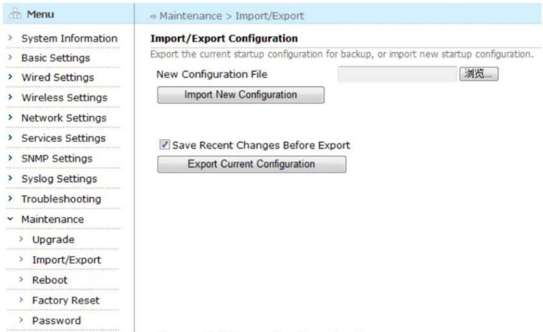
text_image
Menu System Information Basic Settings Wired Settings Wireless Settings Network Settings Services Settings SNMP Settings Syslog Settings Troubleshooting Maintenance Upgrade Import/Export Reboot Factory Reset Password Import/Export Configuration Export the current startup configuration for backup, or import new startup configuration. New Configuration File Import New Configuration Save Recent Changes Before Export Export Current ConfigurationFigure 11-5 Export Configuration Page
11.2.2. Import Configuration
To import new configuration, click "Browse" button and choose the configuration file to be imported from the pop-up window, such as D:\device.conf, and click "Import New Configuration" button, the configuration file will be imported into the device.
| Menu | → Maintenance > Import/Export |
| System Information Basic Settings Wired Settings Wireless Settings Network Settings Services Settings SNMP Settings Syslog Settings Troubleshooting Maintenance Upgrade Import/Export Reboot Factory Reset Password | Import/Export Configuration Export the current startup configuration for backup, or import new startup configuration. New Configuration File D:\device.conf Browse Import New Configuration Save Recent Changes Before Export Export Current Configuration |
Figure 11-6 Import Configuration Page
During the process, the following page will appear to ask for rebooting the device. The device will use the new configuration file after reboot.
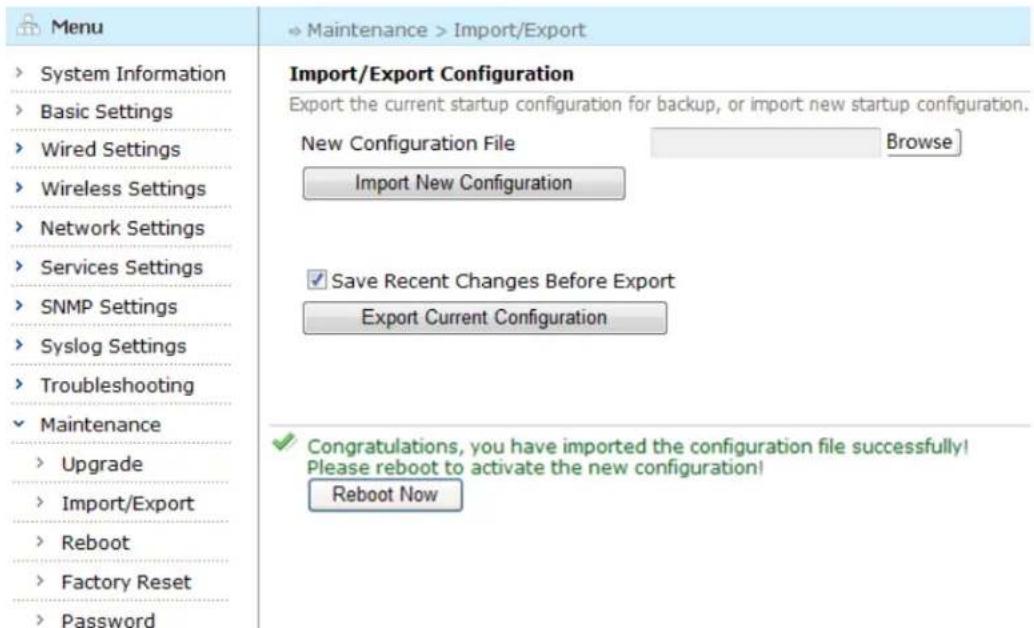
text_image
Menu System Information Basic Settings Wired Settings Wireless Settings Network Settings Services Settings SNMP Settings Syslog Settings Troubleshooting Maintenance Upgrade Import/Export Reboot Factory Reset Password Import/Export Configuration Export the current startup configuration for backup, or import new startup configuration. New Configuration File Browse Import New Configuration Save Recent Changes Before Export Export Current Configuration Congratulations, you have imported the configuration file successfully! Please reboot to activate the new configuration! Reboot NowFigure 11-7 Import Configuration Successfully
11.3. Reboot
To reboot the device, click "Maintenance" -> "Reboot" from the left-side menu tree. Click "Yes, perform reboot" to reboot the device immediately, or select "No, return to homepage" to cancel.
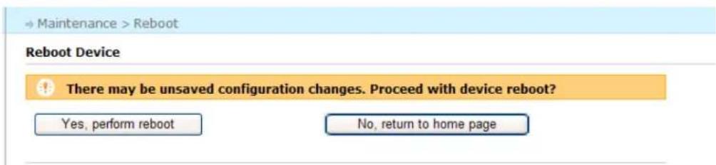
text_image
Maintenance > Reboot Reboot Device There may be unsaved configuration changes. Proceed with device reboot? Yes, perform reboot No, return to home pageFigure 11-8 Reboot Page
Click "Yes, perform reboot" button, the device will reboot.
Reboot

Device rebooting, please wait...
System is rebooting, please wait.
Figure 11-9 Reboot Process Page
In the reboot process, the user can not conduct any operation.
11.4. Factory Reset
To restore factory default setting, click "Maintenance" -> "Factory Reset" from the left-side menu tree. Click "Yes, perform factory reset" to restore the factory setting immediately, or select "No, return to homepage" to cancel.
← Maintenance > Factory Reset
Reset to factory default state
Restore configuration to factory default and reboot?
Yes, perform factory reset
No, return to home page
Figure 11-10 Factory Reset
Click "Yes, perform factory reset", the device will reboot.
Reboot

Device rebooting, please wait...
System is rebooting, please wait.
Figure 11-11 Reboot Process Page
Another method of restoring the unit to the factory default state is:
• Power off the device, power it back on, and wait for about 60 seconds
Aruba Mesh Router Web-based Configuration Guide
- Repeat the above procedure six times
- The seventh time the unit powers on, it should revert to factory default state.
The device will restore factory settings after reboot. And WMI connection fails, the user need to re-configure IP address via CLI, and log in WMI page using the configured IP address.
11.5. Change Password
To ensure the security of device, we recommend users to change password regularly.
To change password, click "Maintenance" -> "Password" from the left-side menu tree. Enter current password in the "Old password" box.
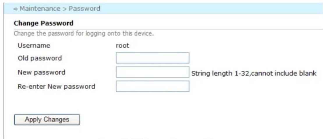
text_image
→ Maintenance > Password Change Password Change the password for logging onto this device. Username root Old password New password String length 1-32,cannot include blank Re-enter New password Apply ChangesFigure 11-12 Change Password Page
The password must be an alphanumeric string between 1-32 characters long that starts with a letter and has no spaces. When the password is changed, users are required to login again for any operation.